Embed Size (px)
Citation preview
Behaviour Planning for Autonomous VehiclesNagarjun [email protected]
Abstract—This paper proposes an approach of safe navigationwhile Lane changing in road case scenario. The approach is tobuild a cost based decision making module for lane changing taskwith multi agents for avoiding collisions. The cost libraries used inthis model helps to make decision of when to change a Lane. Theproject is built on modelling exiting Lane Following and HighwayLane change MATLAB models. The paper describes threemodels of the project. Model-1 is working method of simulationimplementation. Model-2 is method of creating decision makingmodule using safe zones and Model-3 is proposed method ofcreating decision making module using cost functions.
Index Terms—Simulink, MATLAB, Lanes, sensors, EGO ve-hicles, MIOs.
I. INTRODUCTION
The safe navigation for autonomous vehicles depends onmany factors when comes to planning. In general planningframework can be divided into Motion planning, Mission plan-ning, behaviour planning. Motion planning generates desiredtrajectory of the vehicle considering the dynamic parametersand output of steering and throttle. Mission planning is tooptimizes the path to achieve different checkpoints consideringthe arrival time, distance or different required maneuvers. Be-haviors planning makes tactical driving decisions about suchthings as distance keeping, Lane changing and neighbouringvehicle interactions [1].
The aim of this project is to build a decision making modulebased on cost functions[2]. The project is modified based onreference Highway Lane change [3].
In order to create a Autonomous Lane change model. Firstwe need to understand how Lateral[4] and Longitudinal control[5] is built, which is required to create Traffic Jam assist [6].The reference Model created by MathWorks for Traffic Jamassist is also known as Lane Following Control with SensorFusion and Lane Detection [7]. Which is modelled further withLane change controller [8] to design a highway Lane change[9].
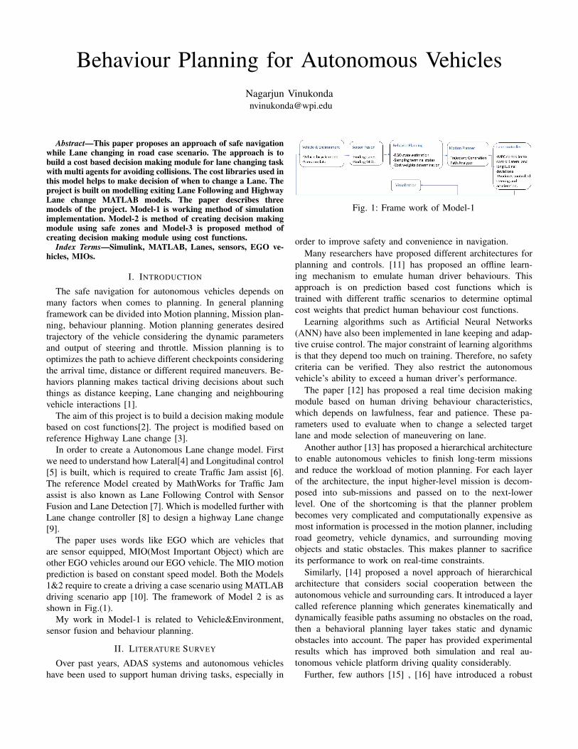
The paper uses words like EGO which are vehicles thatare sensor equipped, MIO(Most Important Object) which areother EGO vehicles around our EGO vehicle. The MIO motionprediction is based on constant speed model. Both the Models1&2 require to create a driving a case scenario using MATLABdriving scenario app [10]. The framework of Model 2 is asshown in Fig.(1).
My work in Model-1 is related to Vehicle&Environment,sensor fusion and behaviour planning.
II. LITERATURE SURVEY
Over past years, ADAS systems and autonomous vehicleshave been used to support human driving tasks, especially in
Fig. 1: Frame work of Model-1
order to improve safety and convenience in navigation.Many researchers have proposed different architectures for
planning and controls. [11] has proposed an offline learn-ing mechanism to emulate human driver behaviours. Thisapproach is on prediction based cost functions which istrained with different traffic scenarios to determine optimalcost weights that predict human behaviour cost functions.
Learning algorithms such as Artificial Neural Networks(ANN) have also been implemented in lane keeping and adap-tive cruise control. The major constraint of learning algorithmsis that they depend too much on training. Therefore, no safetycriteria can be verified. They also restrict the autonomousvehicle’s ability to exceed a human driver’s performance.
The paper [12] has proposed a real time decision makingmodule based on human driving behaviour characteristics,which depends on lawfulness, fear and patience. These pa-rameters used to evaluate when to change a selected targetlane and mode selection of maneuvering on lane.
Another author [13] has proposed a hierarchical architectureto enable autonomous vehicles to finish long-term missionsand reduce the workload of motion planning. For each layerof the architecture, the input higher-level mission is decom-posed into sub-missions and passed on to the next-lowerlevel. One of the shortcoming is that the planner problembecomes very complicated and computationally expensive asmost information is processed in the motion planner, includingroad geometry, vehicle dynamics, and surrounding movingobjects and static obstacles. This makes planner to sacrificeits performance to work on real-time constraints.
Similarly, [14] proposed a novel approach of hierarchicalarchitecture that considers social cooperation between theautonomous vehicle and surrounding cars. It introduced a layercalled reference planning which generates kinematically anddynamically feasible paths assuming no obstacles on the road,then a behavioral planning layer takes static and dynamicobstacles into account. The paper has provided experimentalresults which has improved both simulation and real au-tonomous vehicle platform driving quality considerably.
Further, few authors [15] , [16] have introduced a robust

prediction-cost function based algorithm for autonomous free-way driving. The prediction engine is built so that the au-tonomous vehicle is able to estimate human drivers’ intentions.And the cost function library is used to help behavior plannersgenerate the best strategies of maneuvering on road. Myproposed work is based on the following authors to create thecost library that helps to make decisions for Lane changing.
III. METHODOLOGY
These are the common methods that can be used for allthree Models.
A. Driving Scenario:
The driving scenario is created with 8 radars and1 camera sensor. The radar sensors are named as: 1)FrontLRR 2)FrontMRR 3)LeftFrontSRR 4)LeftRearMRR5)LeftRearSRR 6)RightFrontSRR 7)RightRearMRR8)RightRearSRR. The SRR stands for Short-Range, MRR forMid-Ranged, LRR for Long-Range. Each has its propertiesand the complete sensor addition is as shown in Fig.(2).
Fig. 2: Sensors block
After Addition of sensors we create a the road case scenarioby adding reference waypoints to our model and other actors.Which results in 3D simulation in birds eye plot as shown inFig.(3).
Fig. 3: Sensors block
After creating the scenario we need to export it intoMATLAB function. The driving case scenario cant providereference signals. It provides actors profiles which includespose, velocity, index. We can generate our reference signalswhich will be required for MPC controller further using”helperCreateReferencePath.m” file provided by MATLAB.
Later, we need to send our reference signals from MATLABeditor to Simulink. In our I am importing signals as a constantcalled ”globalplanpoints” as shown in Fig.(5).
Fig. 4: Vehicle and Environment module
B. Finding MIOs:
In order to find MIOs, we first need to find other lanesaround EGO lane. For which we use MATLAB functioncalled ”PackLanes.m” which provides curvatures of EGO laneand its next lane. Next we need to build a function to findMIOs. This can be either done by calculating Safe Zones orcalculating time of contact(TTC). In this model I have usedSafe Zone Calculations. The safe zone is distance for whichour EGO vehicle wouldn’t be in contact with other actors.This is calculated with the formula as stated in eq(1). vf isrelative velocity of forward vehicle, ρ is response time of EGOvechile to perform any activity, ab is brake deceleration of ourEGO car. As stated previously MIOs are considered to movein constant velocities hence, we take deceleration as 0.4*agi.e. ag is 9.8 m/s2.
vf ∗ ρ+ v2f/(2 ∗ ab) (1)
This formula is applied for every MIO which is availablein our lane or next Lane. While calculating safe zones, werequire to state whether calculated distance is safe or not.For which we introduce a parameter called FCW(ForwardCollision Warning). While detecting MIOs we need to stateFCW=3 if vechile ahead is having more than safe distancefrom our EGO vehicle. FCW=2, if relative speed is decreasingand FCW=1, if a MIO is detected inside our safe zone.
C. Pseudo code:
The Algorithm-1 is pseudocode to calculate MIOs. Insteadof safe zones we can also calculate TTC in similar way throughtaking relative distance with speed.
IV. MODEL-1
This is the model of working simulation.
Page 2 of 7

Algorithm 1: General implementation of finding MIOs
Identify the lane curvatures of our lane and next lane.Initialize EGO parameters like Min and Max position EGOcan reach.Initialize MIOs.for Every Target actors found from sensor data: do
Find its lateral and longitudinal positions relative to ourEGO vehicle.Find lateral positions of left and right EGO lane.if MIO lateral and longitudinal positions lay within Laneboundaries then
Store that MIO track index.end if
end forif The MIO track index>0 (i.e. MIO is detected) then
Store its position and velocityCalculate Safe Zone or Time of contact
end ifStore the data in MIO class.
A. Behaviour Planner
:The behaviour planner consists of estimating EGO vehicle
state, sampling terminal states and defining cost weights forEGO vehicle.
The terminal state will define sampling behaviour for gener-ating multiple candidate trajectories. These terminal states willbe used to divide the longitudinal state into more complextrajectory. The feasibility parameters are required to avoidexcessive curvatures and accelerations. First we need to samplemultiple candidate trajectories for each pair of state (start, ter-minal states). Evaluate cost for each of these trajectories whichdepends upon time, Arc length, deviation, Lateral/Longitudinalsmoothness[17].
Followed by feasibility check for all these trajectories andthen collision check for every trajectory using state validator.Finally, with these results we can choose feasible collision freetrajectory with minimal cost. Where these two tasks are donein Motion Planner.
In order to do this first we need to create occupancy mapusing state validator. The state validator creates a ”valida-torOccupancyMap” built by MATLAB. In my scenario, I haveprovided binaryOccupancyMap as 100*75 which is differentfrom default. I also require to provide my Lanewidth whichis 4.5m. The occupancy map is useful to calculate if there isleft and right lane available after lane change and finding no.of lanes available to change based on the trajectory generatedby reference path as shown in Fig.(5)
We also require to calculate deviation of our EGO vehicleboth lateral and longitudinal from reference path. Next weneed to calculate no.of lateral and longitudinal terminal statessamples as shown in Fig.(6).
In the calculation of Longitudinal Samples I have taken de-creased my Planning Horizon to 45m as my scenario is having
Fig. 5: EGO vehicle while changing the Lane
Fig. 6: Lateral and Longitudinal samples
more curved roads and the longitudinal planning requires theroad to be straight. I have increased no.of longitudinal sampleto 2 as my scenario has less no.of cars and I don’t require tomaneuver more to get complex trajectories.
Similarly, in lateral sampling I require to change my Lanewidth. As no. of Lanes in my scenario are three, I dont requireto change the sampling process. But, if there is a scenariowhere no. of Lanes more than 3 or we want to deviate twolanes at once, we require to calculate lateral states.
The velocity sampler is intended to consider lane speed ve-locity profile generated for the reference path while generatingtrajectory. I have changed the ego set velocity to 20m/s. Thereis no use of using acceleration sampler since, we are usingconstant velocity model, so I have discarded it and providedan empty array to avoid index error. Further I have changed theweights of the costs for time, ARClength, lateralsmoothness to0.2, 0.2, 0.4 respectively. The following is the Module diagramof behaviour planner as shown in Fig.(7).
Fig. 7: Behaviour Planner Module
For my working model I have used Motion planner and Lanechange controller provided by MATLAB. And the followingis the result of my scenario as shown in Fig.(8).
Page 3 of 7

Fig. 8: Model-1 result and Module
B. Model-1 Results:
The following are the results of simulation Model-1Fig.(11). The Fig.(9) shows lateral offset provided by ourreference vs lateral offset after tuned by MPC controller.Fig.(10) shows the heading angle deviation. Heading angle isangle between EGO heading direction and Longitudinal axis.Although in video there are unexpected sharp turns the resultare good. The reason for these sharp turns might be due tocost weights provided to lateral and longitudinal smoothness,planning horizon and no.of samples created.
Fig. 9: Later offset, yellow: reference provided and pink: MPCtuned lateral offset
V. MODEL-2
This model is made from Lane Following with sensor modelfrom MATLAB, which is been modified to our customs tocreate a state flow diagram for decision making module [18].The following is the Model-2 Fig.(12).
We Follow the same steps for building vehicle Environment,sensor fusion and finding MIOs. After finding MIOs we create
Fig. 10: Heading, red: reference provided and green and blue:MPC tuned heading angle and its next iteration respectively.
Fig. 11: Lanechange result
a Lane change planner which requires a Decision makingmodule as shown in Fig.(13) state flow diagram.
Inside the state flow diagram we have created the deci-sion making Logic as follows Fig(15). Here the data, data1,data2, data3, data4, data5 are MIO.Rear, MIO.LeftFront,MIO.LeftRear, MIO.RightFront, MIO.RightRear respectively.LCActive is state of Lane change mode whether it is activeor inactive. This is the input from Lane change Planner whichconsists trajectory generator. The duration is Time of contact.Duration(FCW) is a function which determines TTC with MIOin current EGO Lane. LCParam is either 1 or 2 for left andright lane respectively.
First we check if there are vehicles around us. If thereare no MIOs available in LeftFront and LeftRear then wechange Left else we change Right. A trigger message is set.When LCTrigger is false then we start to change the lane.Finally, the LCstatus and LCParam are provided as output forthe Lane change Planner as shown in Fig.(14). This plannercalculates reference trajectory for changing lane, Lane centersand velocity of EGO after Lane change. Which are further fed
Page 4 of 7
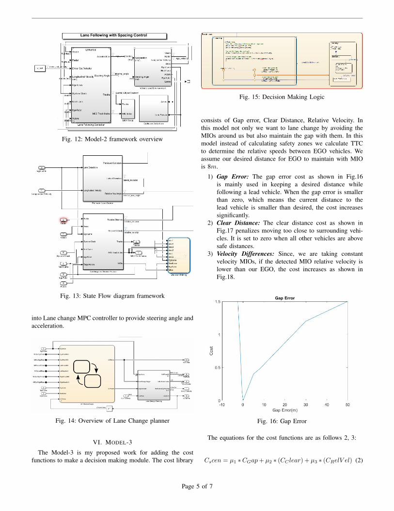
Fig. 12: Model-2 framework overview
Fig. 13: State Flow diagram framework
into Lane change MPC controller to provide steering angle andacceleration.
Fig. 14: Overview of Lane Change planner
VI. MODEL-3
The Model-3 is my proposed work for adding the costfunctions to make a decision making module. The cost library
Fig. 15: Decision Making Logic
consists of Gap error, Clear Distance, Relative Velocity. Inthis model not only we want to lane change by avoiding theMIOs around us but also maintain the gap with them. In thismodel instead of calculating safety zones we calculate TTCto determine the relative speeds between EGO vehicles. Weassume our desired distance for EGO to maintain with MIOis 8m.
1) Gap Error: The gap error cost as shown in Fig.16is mainly used in keeping a desired distance whilefollowing a lead vehicle. When the gap error is smallerthan zero, which means the current distance to thelead vehicle is smaller than desired, the cost increasessignificantly.
2) Clear Distance: The clear distance cost as shown inFig.17 penalizes moving too close to surrounding vehi-cles. It is set to zero when all other vehicles are abovesafe distances.
3) Velocity Differences: Since, we are taking constantvelocity MIOs, if the detected MIO relative velocity islower than our EGO, the cost increases as shown inFig.18.
Fig. 16: Gap Error
The equations for the cost functions are as follows 2, 3:
Cscen = µ1 ∗CGap+ µ2 ∗ (CC lear) + µ3 ∗ (CRelV el) (2)
Page 5 of 7

Fig. 17: Clear Distance
Fig. 18: Relative Velocities
Ctotal =∑
Cscen/n (3)
Cscen is total cost of a scenario, µ1,µ2, µ3 cost are weights,n is no. of scenarios, Ctotal is average total cost evaluated forall scenarios.
We are require to tune our cost weights and for calculatedCscen if the cost is greater than threshold Ctotal then wetrigger the Lane change in the decision Module.
The cost weights are taken based on trail and error method.The following table shows the values taken during experimentTable.I.
The experiment 1,2 lead to collision of EGO vehicle withMIO and exp 3 lead to No lane change even though itsnecessary. Exp 4 provided Lane change without collision butmaintaining the gap between EGO and MIO very small. Exp5is able to change lane without collision but its leads to collisionat end of scenario, which is neglected. We considered thresholdfor scenario as 65.
Exp.No µ1 µ2 µ3 scenario1 20 60 40 Collision2 10 30 20 Collision3 6 30 70 No Lane change4 5 40 10 Success5 30 15 20 Unsuccessful
TABLE I: The cost weights considered
A. Decision Making Module:
The decision making module is similar to Model-2 wherewe use Stateflow chart with modifications of adding costfunctions, weights and Motion metrics. The cost functionsimported into simulink using variables for workspace andweights are provides as constants in simulink model. Themotion metrics used are to check the collision when runningthe model. The decision making module in state flow chart isdesigned as shown in pseudo code. The sub pseudo codes areavailable in Appendix.
Algorithm 2: Cost-Based decision making module
Initialise isMIOs, isLCActive, isFCW,isCollsion as FalseGet Lane Boundaries, centers and index of current LaneCheck if MIO is detected in current Laneif isMIO=True then
CheckFCW i.e. check forward collisionif isFCW=True then
Check if Left Lane change is safe using TTCif If safeLF & safeLR then
Trigger Lane change()Check if Right Lane change is safe using TTC
else if safeRF & safeRR thenTrigger Lane change()
elseLCTrigger =TrueisLCActive = FalseCheck Collision()
end ifelse
return to check if MIO detectedend if
end ifSend LCParam and LCstatus outputs
VII. FUTURE SCOPE AND CONCLUSION
In this project, I have implemented simulation setup forlane changing task for my created scenario(Model-1). Theproject requires comprehensive understanding of MATLABand Simulink. The Model-2 requires to create a Lane changePlanner Module as described previously which consists ofTrajectory Generator, Path Analyser, Virtual Lane centers andReference velocity of EGO calculator. In given amount of timeI was able to create the state flow diagram for decision makinglogic. In future, to further continue Model-2 we require tocreate Lane change planner.
Page 6 of 7

Further, Model-3 can also be implemented once Model-2is completed to create a decision making module based oncost functions. For this project we used MATLAB MotionPlanner for experimentation, which require further tuning forbetter results. We can further different costs like distance togoal,etc.
Later, the extension of this project is to export the MATLABmodule into C++ and test it CARLA simulator with differentscenarios.
REFERENCES
[1] J. Kim, K. Jo, D. Kim, K. Chu, and M. Sunwoo, “Behavior and pathplanning algorithm of autonomous vehicle a1 in structured environ-ments,” IFAC Proceedings Volumes, vol. 46, no. 10, pp. 36–41, 2013.
[2] J. Wei and J. M. Dolan, “A robust autonomous freeway driving algo-rithm,” in 2009 IEEE Intelligent Vehicles Symposium. IEEE, 2009, pp.1015–1020.
[3] MathWorks, Highway Lane Change,https://www.mathworks.com/help/driving/ug/highway-lane-change.html.
[4] ——, Lateral controller, https://www.mathworks.com/help/driving/ug/lateral-control-tutorial.html.
[5] ——, ACC controller, https://www.mathworks.com/help/driving/ug/adaptive-cruise-control-with-sensor-fusion.html.
[6] M. Seo Woo Park, Traffic-Jam assist,https://www.mathworks.com/videos/design-and-test-traffic-jam-assist-a-case-study-1527496724717.html.
[7] MathWorks, Lane Following Control with Sensor Fusion and LaneDetection, https://www.mathworks.com/help/driving/ug/lane-following-control-with-sensor-fusion-and-lane-detection.html.
[8] ——, Lane Change Assist Using Nonlinear Model Predictive Con-trol, https://www.mathworks.com/help/mpc/ug/lane-change-assist-using-nonlinear-model-predictive-control.html.
[9] M. Seo-Wook Park, Design and Test Decision-Making,Path-Planning, and Control Modules in Traffic Scenarios,https://www.mathworks.com/videos/design-and-test-decision-making-path-planning-and-control-modules-in-traffic-scenarios-1558962225433.html.
[10] MathWorks, Driving Scenario Designer,https://www.mathworks.com/videos/driving-scenario-designer-1529302116471.html.
[11] J. Wei, J. M. Dolan, and B. Litkouhi, “A learning-based autonomousdriver: emulate human driver’s intelligence in low-speed car following,”in Unattended Ground, Sea, and Air Sensor Technologies and Applica-tions XII, vol. 7693. International Society for Optics and Photonics,2010, p. 76930L.
[12] H. Naseri, A. Nahvi, and F. S. N. Karan, “A real-time lane changing andline changing algorithm for driving simulators based on virtual driverbehavior,” Journal of simulation, vol. 11, no. 4, pp. 357–368, 2017.
[13] M. Montemerlo, J. Becker, S. Bhat, H. Dahlkamp, D. Dolgov, S. Et-tinger, D. Haehnel, T. Hilden, G. Hoffmann, B. Huhnke et al., “Junior:The stanford entry in the urban challenge,” Journal of field Robotics,vol. 25, no. 9, pp. 569–597, 2008.
[14] J. Wei, J. M. Snider, T. Gu, J. M. Dolan, and B. Litkouhi, “A behavioralplanning framework for autonomous driving,” in 2014 IEEE IntelligentVehicles Symposium Proceedings. IEEE, 2014, pp. 458–464.
[15] J. Wei and J. M. Dolan, “A robust autonomous freeway driving algo-rithm,” in 2009 IEEE Intelligent Vehicles Symposium. IEEE, 2009, pp.1015–1020.
[16] J. Wei, J. M. Dolan, and B. Litkouhi, “A prediction-and cost function-based algorithm for robust autonomous freeway driving,” in 2010 IEEEIntelligent Vehicles Symposium. IEEE, 2010, pp. 512–517.
[17] M. Seo-Wook Park, Developing Planning andControls for Highway Lane Change Maneuvers,https://www.mathworks.com/videos/developing-planning-and-controls-for-highway-lane-change-maneuvers-1592820244862.html.
[18] MathWorks, Introducing the New Stateflow Editor,https://www.mathworks.com/videos/introducing-the-new-stateflow-editor-70056.html.
VIII. APPENDIX
Algorithm 3: Trigger Lane change()
Calculate the costif Ctotal < Cscen then
LCTrigger =FalseisLCActive = True
end if
Algorithm 4: Check Collision()
if isCollsion =True thenCollisionCount++
elsereturn to check if MIO detected
end if
Page 7 of 7


![Autonomous vehicles[1]](https://img.pdfslide.net/doc/110x75/54bf07bb4a7959cb478b4592/autonomous-vehicles1.jpg)