Embed Size (px)
Citation preview

BELL 212 Pilot Training Manual
Updated: 25 February 2013 FOR TRAINING PURPOSES ONLY. REVISION NUMBER -00 7- 16
Campbell Helicopters
CHAPTER 7B
POWERPLANT
TABLE OF CONTENTS
ENGINE SYSTEMS ------------------------------------------------------------------------------------------------------------- 19 GENERAL --------------------------------------------------------------------------------------------------------------------- 19 AIR SYSTEMS ---------------------------------------------------------------------------------------------------------------- 19
GENERAL ------------------------------------------------------------------------------------------------------------------ 19 ENGINE INLET AIR ------------------------------------------------------------------------------------------------------ 19 COMPRESSOR AIR ----------------------------------------------------------------------------------------------------- 19 ENGINE BLEED AIR ----------------------------------------------------------------------------------------------------- 21
FUEL SYSTEM --------------------------------------------------------------------------------------------------------------- 21 GENERAL ------------------------------------------------------------------------------------------------------------------ 21 OIL-TO-FUEL HEAT EXCHANGER ---------------------------------------------------------------------------------- 22 ENGINE FUEL FILTER -------------------------------------------------------------------------------------------------- 22 ENGINE FUEL PUMP --------------------------------------------------------------------------------------------------- 23 ENGINE FUEL CONTROL SYSTEMS ------------------------------------------------------------------------------ 23 FLOW DIVIDER AND DUMP VALVE -------------------------------------------------------------------------------- 23
IGNITION SYSTEM --------------------------------------------------------------------------------------------------------- 24 LUBRICATION SYSTEMS ------------------------------------------------------------------------------------------------ 26
GENERAL ------------------------------------------------------------------------------------------------------------------ 26 ENGINE LUBRICATION SYSTEM -------------------------------------------------------------------------------------- 26
GENERAL ------------------------------------------------------------------------------------------------------------------ 26 ENGINE OIL SUMP ------------------------------------------------------------------------------------------------------ 27 ENGINE OIL PUMPS ---------------------------------------------------------------------------------------------------- 28 ENGINE OIL FILTER----------------------------------------------------------------------------------------------------- 28 ENGINE OIL COOLER -------------------------------------------------------------------------------------------------- 28 FUEL/OIL HEAT EXCHANGER --------------------------------------------------------------------------------------- 29 ENGINE OIL SYSTEM OPERATION -------------------------------------------------------------------------------- 29 ENGINE OIL INDICATING SYSTEMS ------------------------------------------------------------------------------- 30 ENGINE OIL PRESSURE GAUGE ----------------------------------------------------------------------------------- 30 ENGINE OIL TEMPERATURE GAUGE ----------------------------------------------------------------------------- 30 ENGINE OIL PRESSURE CAUTION LIGHT ----------------------------------------------------------------------- 31 ENGINE CHIP CAUTION LIGHT ------------------------------------------------------------------------------------- 31 ENGINE OIL SYSTEM LIMITATIONS ------------------------------------------------------------------------------- 31 ENGINE OIL SYSTEM MALFUNCTIONS -------------------------------------------------------------------------- 31

BELL 212 Pilot Training Manual
Updated: 25 February 2013 FOR TRAINING PURPOSES ONLY. REVISION NUMBER -00 7- 17
Campbell Helicopters
COMBINING GEARBOX LUBRICATION SYSTEM -------------------------------------------------------------------- 32 GENERAL ---------------------------------------------------------------------------------------------------------------------- 32 C-BOX OIL SUMP ----------------------------------------------------------------------------------------------------------- 32 C-BOX OIL PUMP ----------------------------------------------------------------------------------------------------------- 33 C-BOX OIL FILTER ---------------------------------------------------------------------------------------------------------- 34 C-BOX OIL COOLER ------------------------------------------------------------------------------------------------------- 34 C-BOX OIL SYSTEM OPERATION ------------------------------------------------------------------------------------- 34 C-BOX OIL INDICATING SYSTEMS ------------------------------------------------------------------------------------ 34 C-BOX OIL PRESSURE GAUGE ---------------------------------------------------------------------------------------- 34 C-BOX OIL TEMPERATURE GAUGE ---------------------------------------------------------------------------------- 35 C-BOX OIL PRESS WARNING LIGHT --------------------------------------------------------------------------------- 35 C-BOX OIL TEMP WARNING LIGHT ----------------------------------------------------------------------------------- 35 CHIP C-BOX CAUTION LIGHT ------------------------------------------------------------------------------------------- 35 C-BOX OIL SYSTEM LIMITATIONS ------------------------------------------------------------------------------------ 35 C-BOX OIL SYSTEM MALFUNCTIONS -------------------------------------------------------------------------------- 35
BELL 212 Pilot Training Manual
Updated: 25 February 2013 FOR TRAINING PURPOSES ONLY. REVISION NUMBER -00 7- 18
Campbell Helicopters
ILLUSTRATIONS
FIGURE 7-12 COMPRESSOR AND POWER TURBINE AIR FLOW -------------- 20 FIGURE 7-14 ENGINE FUEL SYSTEM (ONE FOR EACH ENGINE) -------------- 22 FIGURE 7-15 FUEL CONTROL UNIT ------------------------------------------------------- 23 FIGURE 7-16 FLOW DIVIDER AND DUMP VALVE ------------------------------------ 24 FIGURE 7-17 FUEL NOZZLE ----------------------------------------------------------------- 24 FIGURE 7-18 EXCITER ------------------------------------------------------------------------- 25 FIGURE 7-19 START RELAY ----------------------------------------------------------------- 25 FIGURE 7-21 POWERPLANT LUBRICATION ------------------------------------------- 27 FIGURE 7-23 ENGINE OIL FILTER AND C-BOX OIL FILTER ---------------------- 28 FIGURE 7-24 OIL COOLER FANS ----------------------------------------------------------- 28 FIGURE 7-25 OIL COOLERS ----------------------------------------------------------------- 29 FIGURE 7-26 ENGINE OIL SYSTEM SCHEMATIC ------------------------------------- 30 FIGURE 27A N1 ENGINE CHIP LOCATION --------------------------------------------- 31 FIGURE 27B N1 ENGINE CHIP LOCATION --------------------------------------------- 31 FIGURE 7-28 ENGINE OIL INDICATING SYSTEM ------------------------------------- 32 FIGURE 7-29 C-BOX OIL SYSTEM --------------------------------------------------------- 33 FIGURE 7-30 HOBBS METER ---------------------------------------------------------------- 35

BELL 212 Pilot Training Manual
Updated: 25 February 2013 FOR TRAINING PURPOSES ONLY. REVISION NUMBER -00 7- 19
Campbell Helicopters
ENGINE SYSTEMS GENERAL Each engine is provided with numerous sub-systems to accomplish necessary support functions for normal or special operation. Systems for each engine include air, fuel, ignition, and lubrication systems. Included is a separate lubrication system of the C-box and Power Section fire protection systems. In addition, there are cockpit gauges and warning and caution lights for many of these sub-systems.
AIR SYSTEMS General
Engine air systems include engine inlet air, compressor air, and bleed-air systems.
Engine Inlet Air
Ambient air enters the engine through the engine air inlet wire mesh screen, which is contained within the plenum of the air management system, then to a circular plenum chamber formed by the compressor inlet case, and is directed into the Axial compressor. The three stages of axial compressor provide compressed air and then pass the air onto the centrifugal compressor. The centrifugal compressor air is passed into the annular reverse flow combustion chamber.
Once inside the engine, air is compressed and used for cooling, combustion, pneumatic control air, and customer air purposes (helicopter heating). The compressor and the bleed-air valve control the air within the engine.
Approximately 25% of the compressed air is mixed with fuel and ignited in combustion chamber, and the remainder of the air is directed over the liner for cooling, dilution or insulating the liner.
The expanding gases flow forward, reverse, and flow aft through the gas producer turbine guide vanes and are directed onto the gas producer turbine. The gases drive the compressor and gas producer turbine in a clockwise direction. Approximately 2/3 of the energy drives the compressor and the remaining is used for driving the power turbine.
The remaining gases then pass rearward through the power turbine guide vanes to drive the power turbine (N2) in a counterclockwise direction. Power from this turbine rotation is transmitted through the turbine shaft to the reduction gearbox.
The exhaust gases from the power turbine are directed out the top of the power section into the exhaust duct and enter the ejector system.
Compressor Air
During engine start, the compressor is driven by the starter and rotates to compress air used in combustion and cooling. After starting, the compressor is driven by the N1 turbine wheel and provides compressed air for continued operation. The compressor air (compressor discharge pressure or P3) is also used to provide pneumatic operating air for the engine fuel control system and for customer bleed-air purposes (Figure 7-12).
The compressor is designed to be most efficient at N1 speeds of approximately 85% and above. Engine operation and acceleration at speeds below 85% may result in compressor stall. However, an automatic compressor bleed-air valve is installed to provide low N1 rpm anti-stall acceleration and operation. The bleed-air valve is located on the bottom of the compressor case of the engine, in between

BELL 212 Pilot Training Manual
Updated: 25 February 2013 FOR TRAINING PURPOSES ONLY. REVISION NUMBER -00 7- 20
Campbell Helicopters
Figure 7-12 Compressor and Power Turbine Air Flow
compressor stage 3 and the centrifugal compressor. Its operation is completely automatic and functions as a result of two different air pressures, one between compressor stage 3 and the centrifugal compressor and the other taken from compressor discharge pressure (P3).
During low-speed N1 acceleration, with compressor speeds below 87-93% N1, the valve is open (Figure 7-13a) to dump the stage 3 air. Venting the excess interstage air prevents compressor stalls that might occur due to inter-stage turbulence. As the compressor efficiency increases to normal N1 operating ram (87 to 93%, depending upon OAT), P3 increases significantly and closes the valve (Figure 7-13b).
In this way the Bleed Valve provides the anti-stall characteristics in low power
operation, and the valve closes for high power operation.
Figure 7-13a Bleed-Air Valve OPEN
The bleed valve is a piston-type assembly,

BELL 212 Pilot Training Manual
Updated: 25 February 2013 FOR TRAINING PURPOSES ONLY. REVISION NUMBER -00 7- 21
Campbell Helicopters
secured to the gas generator case. A diaphragm that permits full travel in either direction supports the piston, full open or full closed. Interstage air, P2.5, is vented to the top of the valve through the slots in the compressor case immediately after the axial compressor. The (Centrifugal) compressor discharge air, P3, is furnished through an internal tube and primary orifice to the bottom of the piston. A convergent-divergent orifice vents the P3 air from the bottom of the diaphragm to atmosphere (Pa). Differences in pressure on the diaphragm positions the piston fully closed or fully open. When P3 air reaches a predetermined pressure value, the convergent-divergent orifice becomes choked and the pressure on bottom side closes the valve to stop interstage air bleed. Below the pressure at which the orifice chokes, the valve will open, dumping interstage air.
Figure 7-13b Bleed-Air Valve CLOSED
Since the convergent-divergent orifice is vented to atmosphere, the choking of the orifice compensates for altitude. Thus at altitude, the valve will close earlier. There is no caution or warning lights associated with the compressor bleed-air valve. However,
failure of the valve to function correctly may be indicated in one of two ways. If the valve is closed during engine start and acceleration, indications may include compressor stalls, the accompanying noise, and very slow N1 acceleration. If the valve fails to close as the N1 rpm reaches normal operating range, indications are low torque with high N1 rpm, particularly noticeable during the power assurance check.
Engine Bleed Air
Engine bleed air is taken after centrifugal compression and is referred to as "P3 air.'' P3 air is used as one of the motive forces of the engine fuel control. After regulation by the fuel control, P3 air becomes governor reset pressure, or PG, which controls automatic fuel control operation.
Engine bleed air is used as the source for airframe heating and windshield defogging. An electrically actuated bleed-air valve controls the output of the air from the compressor. Electrical switches labeled for the associated system, such as the HEATER switch normally control bleed-air valves. Additional customer ports are available on the engine to use for optional equipment such as air conditioning.
FUEL SYSTEM General
Each engine has a separate fuel system including various sub-systems that perform specific functions for the fuel passing through it. Engine fuel systems include an oil-to-fuel heat exchanger, a fuel filter, an engine-driven fuel pump, auto/manual fuel control units, a flow divider and dump valve, fuel manifolds, and fuel nozzles. The pilot controls each engine's fuel system by use of the twist-grip throttles, idle stop switch, GOV MANUAL-AUTO switches, RPM INC-DECR switch, and collective inputs (Figure 7-14).

BELL 212 Pilot Training Manual
Updated: 25 February 2013 FOR TRAINING PURPOSES ONLY. REVISION NUMBER -00 7- 22
Campbell Helicopters
Oil-to-Fuel Heat Exchanger
Airframe fuel enters the oil-to-fuel heat exchanger mounted on top of the N1 accessory section and passes through coiled tubing surrounded by hot engine oil. Heat from the engine oil is transferred to the fuel to ensure no ice crystals are present and that the fuel is at optimum operating temperature. The warmed fuel exits the exchanger through a thermostatic control valve which regulates the flow of hot engine oil within the exchanger, thus providing the desired level of fuel heating. There are no cockpit indications for the oil-to-fuel heat exchanger.
Engine Fuel Filter
The Fuel Filter is located on the Engine Fuel Pump/Automatic Fuel Control (AFCU) Assembly on the N1 Accessory Gear Case. Heated fuel enters the engine fuel filter where contaminants are screened by a 10-micron filter to ensure that only clean fuel enters the fuel control. The filter includes
an impending-bypass switch, a spring-loaded-closed bypass valve, and a filter drain system to provide fail-safe operation.
The impending-bypass switch monitors fuel pressure both entering and exiting the filter. If the difference between the two pressures exceeds 1.4 psid, the switch closes and illuminates the FUEL FILTER caution panel light. Illumination of the caution light indicates that some clogging of the filter exists but that fuel is still flowing through and being cleaned by the filter. The pilot should consult the manufacturer's FM for appropriate action.
If the pressure differential exceeds 3 psid, the bypass valve is forced open, allowing unfiltered fuel to pass on to the rest of the engine fuel system. If a significant amount of contaminated fuel bypasses the filter, fuel control problems could occur. There is no cockpit indication when the filter is actually bypassed, and no indication on the filter bypass valve.
Figure 7-14 Engine fuel System (one for each engine)
A fuel filter drain system provides a method

BELL 212 Pilot Training Manual
Updated: 25 February 2013 FOR TRAINING PURPOSES ONLY. REVISION NUMBER -00 7- 23
Campbell Helicopters
to remove contamination that has accumulated in the filter. The filter should be drained daily at the start of the exterior inspection, using the procedures outlined in the manufacturer's approved FM.
Engine Fuel Pump
The engine fuel pump is a geared, positive displacement pump, driven by the N1 accessory section. The engine fuel pump raises fuel pressure to approximately 850 psi, at 100% N1 rpm, is lubricated by the fuel passing through it, and provides the hydraulic operating power for the engine's hydro-pneumatic fuel control units. The center pad on the accessory gearbox drives the fuel pump.
The output of the positive displacement pump in excess of the power section requirement is returned to the inlet of the pump through a bypass line.
The engine fuel pump is designed to provide sufficient fuel flow for the approved operating envelope and should also maintain sufficient fuel flow below 5,000 feet MSL even if both airframe boost pumps fail. However, because of the high pressure demands of the engine fuel system, if an engine fuel pump fails, that engine flames out. There are no cockpit indications for engine fuel pump operation. Even at Sea Level Pressure, the power sections should not be operated without engine pump pressure.
Engine Fuel Control Systems
The primary purpose of each engine's fuel control system is to ensure that the engine produces the correct amount of power to maintain the preselected N2/rotor rpm in flight. This is accomplished by both engines' fuel control units (FCU’s) operating together in the automatic modes. In the event of a malfunction in an engine's automatic FCU, the pilot can easily control the affected engine by selecting the manual mode of
operation and then manually controlling fuel flow to the engine with the twist-grip throttle (Figure 7-14).
Figure 7-15 Fuel Control Unit
The pilot establishes the operating mode for each engine's FCU by selecting either AUTO or MANUAL on the GOV switch. If the MANUAL mode of fuel control operation is selected, the GOV MANUAL caution light illuminates for the selected engine. Either or both engines may be operated in AUTO or MANUAL mode. However, the pilot must exercise extreme care to ensure that rotor, N2, and other engine limits are not exceeded while operating in the MANUAL mode.
The fuel control units are hydro-pneumatic devices that utilize fuel pressure, N2 governor reset pressure, and PG pneumatic air as operating and controlling forces.
Flow Divider and Dump Valve
Pressurized-metered fuel from the engine's FCU is sent through external lines to the rear underside of the N1 section, where it enters the flow divider and dump valve (Figure 7-16). The primary and secondary fuel nozzle manifolds are connected to the flow divider and dump valve and distribute the fuel to the fuel nozzles in the combustor section of the engine.
During starting, as N1 rpm increases, fuel
BELL 212 Pilot Training Manual
Updated: 25 February 2013 FOR TRAINING PURPOSES ONLY. REVISION NUMBER -00 7- 24
Campbell Helicopters
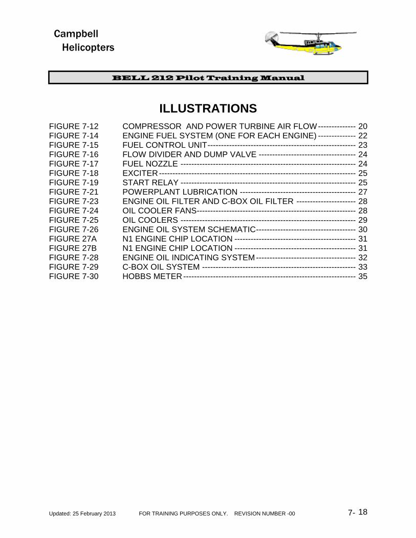
pressure increases.
Figure 7-16 Flow Divider and Dump Valve
At approximately 13% N1 rpm, sufficient fuel pressure is produced to open the spring-loaded-closed primary manifold valve and allow fuel to enter the primary fuel manifold, where it is sprayed through seven primary fuel nozzles into the combustor ring. As lightoff occurs and N1 rpm increases, fuel pressure also increases.
At approximately 30% N1 rpm, fuel pressure is increased sufficiently to open a second spring loaded-closed secondary manifold valve, which distributes fuel to the secondary manifold and its seven fuel nozzles. During normal engine operation both spring-loaded valves are fully open, and both fuel manifolds and all 14 fuel nozzles provide a continuous flow of fuel to the combustor.
Figure 7-17 Fuel Nozzle
During engine shutdown, when the throttles are closed, pressurized fuel to the flow divider and dump valve is cut off. The spring-loaded valves close, and fuel flow to the manifolds and nozzles stops. This would normally trap some fuel in the primary and secondary manifolds and nozzles. However, as the spring-loaded valves close, a drain path is opened which allows both the manifolds and nozzles to dump their trapped fuel, thus minimizing the possibility of a hot start occurring during the next engine start. Some Campbell aircraft have a system to recover this dumped fuel. There are no cockpit indications for operation of the flow divider and dump valve other than during normal engine start.
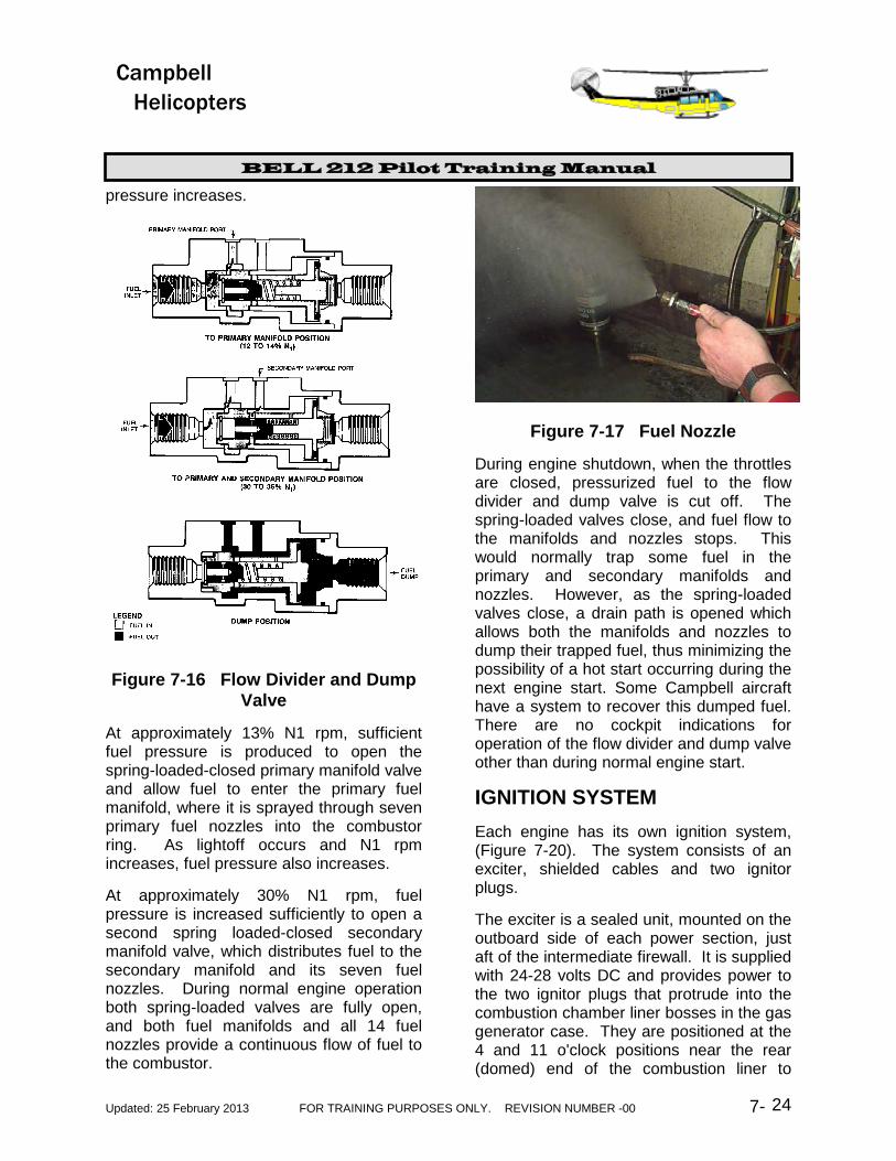
IGNITION SYSTEM Each engine has its own ignition system, (Figure 7-20). The system consists of an exciter, shielded cables and two ignitor plugs.
The exciter is a sealed unit, mounted on the outboard side of each power section, just aft of the intermediate firewall. It is supplied with 24-28 volts DC and provides power to the two ignitor plugs that protrude into the combustion chamber liner bosses in the gas generator case. They are positioned at the 4 and 11 o'clock positions near the rear (domed) end of the combustion liner to
BELL 212 Pilot Training Manual
Updated: 25 February 2013 FOR TRAINING PURPOSES ONLY. REVISION NUMBER -00 7- 25
Campbell Helicopters
insure proper ignition during the starting cycle. The plugs have center positive electrodes surrounded by semi-conducting material across the surface of which sparks are passed.
Figure 7-18 Exciter
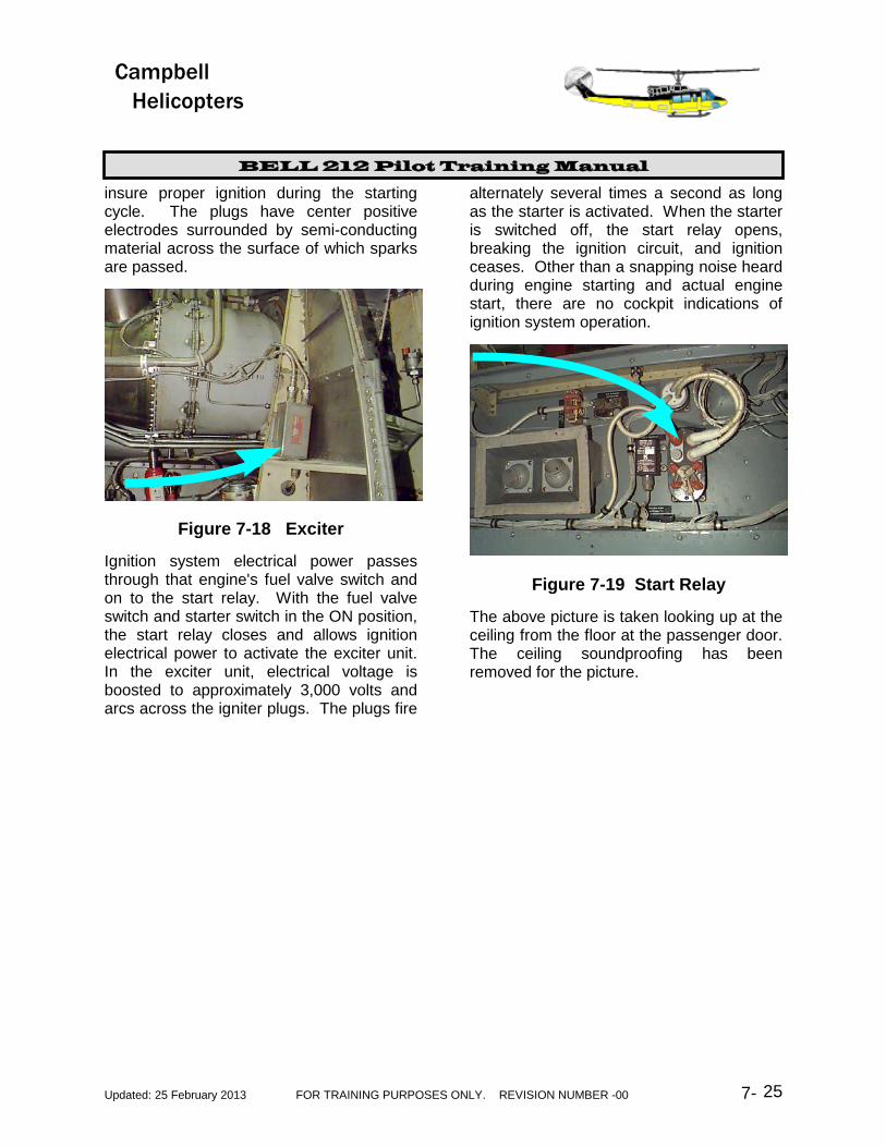
Ignition system electrical power passes through that engine's fuel valve switch and on to the start relay. With the fuel valve switch and starter switch in the ON position, the start relay closes and allows ignition electrical power to activate the exciter unit. In the exciter unit, electrical voltage is boosted to approximately 3,000 volts and arcs across the igniter plugs. The plugs fire
alternately several times a second as long as the starter is activated. When the starter is switched off, the start relay opens, breaking the ignition circuit, and ignition ceases. Other than a snapping noise heard during engine starting and actual engine start, there are no cockpit indications of ignition system operation.
Figure 7-19 Start Relay
The above picture is taken looking up at the ceiling from the floor at the passenger door. The ceiling soundproofing has been removed for the picture.

BELL 212 Pilot Training Manual
Updated: 25 February 2013 FOR TRAINING PURPOSES ONLY. REVISION NUMBER -00 7- 26
Campbell Helicopters
Figure 7-20 Engine Ignition System
LUBRICATION SYSTEMS
General
The powerplant includes three separate lubrication systems: one for each engine and one for the combining gearbox. Each system is totally independent and self-contained, including its own reservoir, pumps, cooler, filter, plumbing, indicating systems, and caution/warning lights. Engine and C-box oil systems are discussed separately.
All three lubrication systems are wet-sump pressure systems and employ the same principle of operation. The oil is first
pressurized and then sent to be cooled. After cooling, the oil is filtered and then used for lubrication. This ensures that cool clean oil is available for the primary purposes of lubrication to reduce wear and temperature of vital components (Figure 7-21).
Engine Lubrication System
General
Each engine lubrication system includes a tank with sight gauges, a four-element pump, a replaceable filter, a thermostatic cooler, associated plumbing, and indicating

BELL 212 Pilot Training Manual
Updated: 25 February 2013 FOR TRAINING PURPOSES ONLY. REVISION NUMBER -00 7- 27
Campbell Helicopters
systems.
Engine Oil Sump
The lower portion of the N1 accessory section case serves as the engines oil tank and sump (Figure 7-22). Sight gauge provisions are available on either side of the case so that the engine may be installed in either the No. 1 or the No. 2 engine
position. The tank has a capacity of 1.6 U.S. gallons. The quantity should be checked when cold, with the helicopter on a level surface and the engine not operating. Sight gauge markings also include the amount of engine oil to be added if necessary. There are no cockpit indications for engine oil quantity.
Figure 7-21 Powerplant Lubrication

BELL 212 Pilot Training Manual
Updated: 25 February 2013 FOR TRAINING PURPOSES ONLY. REVISION NUMBER -00 7- 28
Campbell Helicopters
FIGURE 7-22 Engine Oil
Engine Oil Pumps
The engine oil pump unit, consisting of one pressure element and three scavenge elements, is mounted in and driven by the N1 accessory section. Any time the N1 section is rotating, the pumps are being driven and provide pressure oil for lubrication and torque sensing. Scavenge oil is returned to the engine oil sump.
Engine Oil Filter
A single, replaceable, cartridge oil filter (Figure 7-23), located at the outboard side of the N2 gear reduction case, cleans impurities from the engine oil. A spring-loaded-closed by-pass valve is incorporated in the filter to prevent a clogged filter from
interrupting oil flow. There is no filter bypass indication for clogged filter.
Engine Oil Cooler
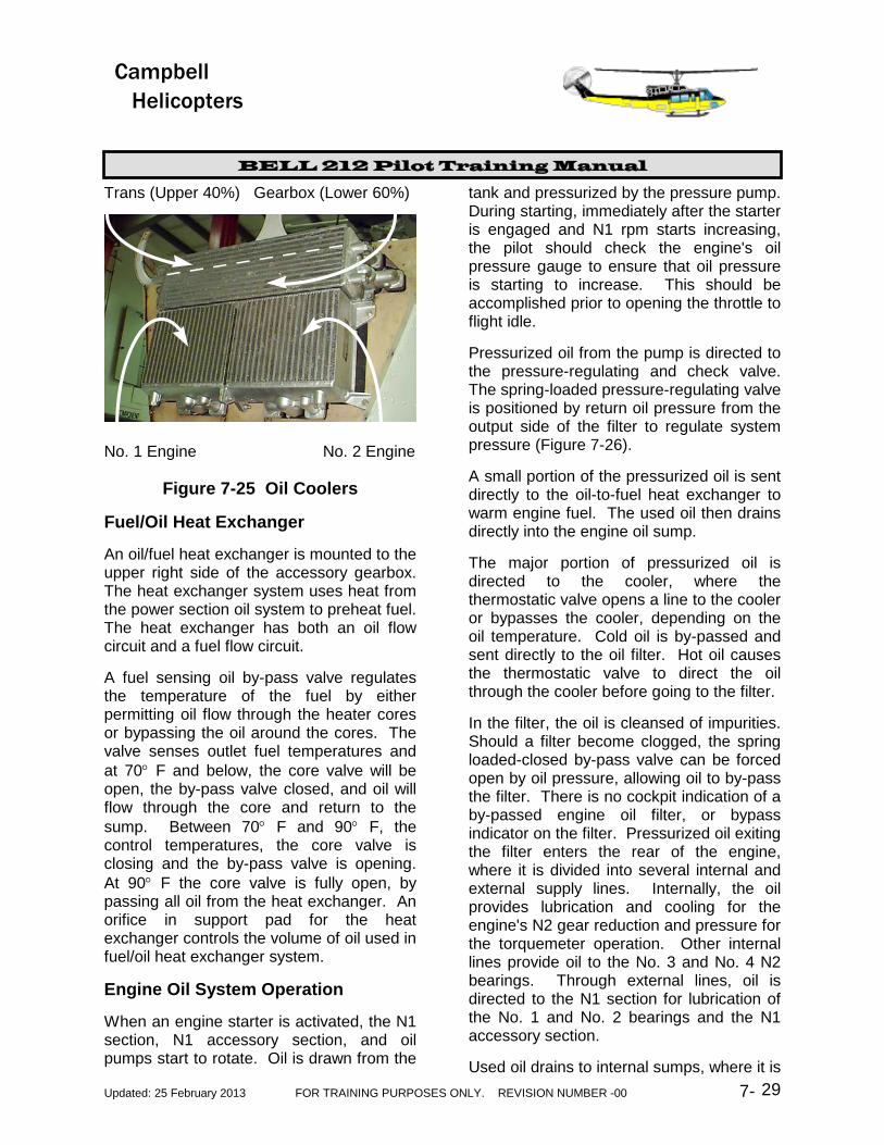
Each oil system has its own thermostatically controlled oil cooler mounted at the rear of the powerplant. A thermostatic valve in the cooler controls the cooling of engine oil to ensure optimum oil temperature. Two blower fans (figure 7-24) driven by each engine's N2 gear reduction section provide cooling air for the engine oil coolers, the C-box oil cooler, and the main transmission oil cooler. All four oil coolers are collocated in a common housing (Figure 7-25).
Figure 7-23 Engine Oil Filter and C box Oil Filter By-pass Button
Figure 7-24 Oil Cooler Fans
BELL 212 Pilot Training Manual
Updated: 25 February 2013 FOR TRAINING PURPOSES ONLY. REVISION NUMBER -00 7- 29
Campbell Helicopters
Trans (Upper 40%) Gearbox (Lower 60%)
No. 1 Engine No. 2 Engine
Figure 7-25 Oil Coolers
Fuel/Oil Heat Exchanger
An oil/fuel heat exchanger is mounted to the upper right side of the accessory gearbox. The heat exchanger system uses heat from the power section oil system to preheat fuel. The heat exchanger has both an oil flow circuit and a fuel flow circuit.
A fuel sensing oil by-pass valve regulates the temperature of the fuel by either permitting oil flow through the heater cores or bypassing the oil around the cores. The valve senses outlet fuel temperatures and at 70° F and below, the core valve will be open, the by-pass valve closed, and oil will flow through the core and return to the sump. Between 70° F and 90° F, the control temperatures, the core valve is closing and the by-pass valve is opening. At 90° F the core valve is fully open, by passing all oil from the heat exchanger. An orifice in support pad for the heat exchanger controls the volume of oil used in fuel/oil heat exchanger system.
Engine Oil System Operation
When an engine starter is activated, the N1 section, N1 accessory section, and oil pumps start to rotate. Oil is drawn from the
tank and pressurized by the pressure pump. During starting, immediately after the starter is engaged and N1 rpm starts increasing, the pilot should check the engine's oil pressure gauge to ensure that oil pressure is starting to increase. This should be accomplished prior to opening the throttle to flight idle.
Pressurized oil from the pump is directed to the pressure-regulating and check valve. The spring-loaded pressure-regulating valve is positioned by return oil pressure from the output side of the filter to regulate system pressure (Figure 7-26).
A small portion of the pressurized oil is sent directly to the oil-to-fuel heat exchanger to warm engine fuel. The used oil then drains directly into the engine oil sump.
The major portion of pressurized oil is directed to the cooler, where the thermostatic valve opens a line to the cooler or bypasses the cooler, depending on the oil temperature. Cold oil is by-passed and sent directly to the oil filter. Hot oil causes the thermostatic valve to direct the oil through the cooler before going to the filter.
In the filter, the oil is cleansed of impurities. Should a filter become clogged, the spring loaded-closed by-pass valve can be forced open by oil pressure, allowing oil to by-pass the filter. There is no cockpit indication of a by-passed engine oil filter, or bypass indicator on the filter. Pressurized oil exiting the filter enters the rear of the engine, where it is divided into several internal and external supply lines. Internally, the oil provides lubrication and cooling for the engine's N2 gear reduction and pressure for the torquemeter operation. Other internal lines provide oil to the No. 3 and No. 4 N2 bearings. Through external lines, oil is directed to the N1 section for lubrication of the No. 1 and No. 2 bearings and the N1 accessory section.
Used oil drains to internal sumps, where it is

BELL 212 Pilot Training Manual
Updated: 25 February 2013 FOR TRAINING PURPOSES ONLY. REVISION NUMBER -00 7- 30
Campbell Helicopters
picked up by the three scavenge pumps and returned to the sump in the N1 accessory section.
Engine Oil Indicating Systems
Each engine oil system includes a combined temperature and pressure gauge (Figure 7-28) and OIL PRESSURE and engine CHIP caution lights.
Engine Oil Pressure Gauge
An engine oil pressure transmitter, located at the lower right corner of the N1 accessory section, senses return line oil pressure and displays it in psi on the combined temperature and pressure gauge. The transmitter uses 26.5-VAC electrical power and is protected with the ENG 1 or 2 OIL PRESS circuit breakers. Loss of electrical power results in loss of oil pressure indications.
Figure 7-26 Engine Oil System Schematic
Engine Oil Temperature Gauge
An engine oil temperature bulb, located next to the oil pressure transmitter in the lower corner of the N1 accessory section, senses
return line oil temperature and displays it in degrees Centigrade on the combined temperature and pressure gauge. The temperature bulb uses 28-VDC electrical power and is protected with the associated

BELL 212 Pilot Training Manual
Updated: 25 February 2013 FOR TRAINING PURPOSES ONLY. REVISION NUMBER -00 7- 31
Campbell Helicopters
OIL TEMP circuit breaker. Loss of electrical power results in loss of oil temperature indications.
Engine OIL PRESSURE Caution Light
A normally closed oil pressure switch is located at the entrance to the oil filter. As engine oil enters the filter, pressure opens the pressure switch at 40 psi and extinguishes the associated OIL PRESSURE caution light. If engine oil pressure drops below 31-psi, the switch closes and illuminates the caution panel light. The switch uses 28-VDC electrical power and is protected with the MASTER CAUTION circuit breaker located on the overhead panel.
Figure 27a N1 Engine Chip Location
Figure 27b N1 Engine Chip Location
The pilot should keep in mind that the 31-psi value for caution panel light illumination
is well below the normal green range minimum for system operation of 80 psi. Therefore, the pilot should not rely on the OIL PRESSURE caution light as the primary indication of low engine oil pressure.
Engine CHIP Caution Light
Each engine incorporates two chip detectors: one in the N1 accessory section oil sump and the other located in the N2 gear reduction case sump. A metal chip that comes in contact with either detector completes the circuit and illuminates the engine CHIP caution panel light. Both detectors use 28-VDC electrical power from the MASTER CAUTION circuit breaker.
Engine Oil System Limitations
The pilot should consult the limitations section of the manufacturer's approved FM for engine oil limits.
Engine Oil System Malfunctions
Loss of engine oil pressure during engine operation requires that the engine be shut down. The pilot should consult the manufacturer's approved FM for specific procedures.
Overheating of engine oil, while not specifically covered in the FM may be nearly as critical as loss of oil pressure. In the absence of manufacturer's procedures, the pilot should reduce engine power to determine if the engine oil temperature returns to within the continuous range. If engine oil temperature does not decrease, it is suggested that the same procedures as those for loss of engine oil pressure be followed.
Illumination of an engine CHIP caution panel light requires a landing as soon as practicable. The pilot should consult the manufacturer's approved FM for specific procedures.

BELL 212 Pilot Training Manual
Updated: 25 February 2013 FOR TRAINING PURPOSES ONLY. REVISION NUMBER -00 7- 32
Campbell Helicopters
Figure 7-28 Engine Oil Indicating System
Combining Gearbox Lubrication System
General The C-box lubrication system includes a sump with sight gauge, a pump, a filter, an oil cooler, associated plumbing, and indicating systems.
C-Box Oil Sump The lower portion of the center section of the combining gearbox case serves as the C-box oil sump and tank (Figure 7-29). A sight gauge, located on the rear of the case, provides a method of checking lubricant level. The gauge is difficult to see and is best viewed with a flashlight through the right-side fire extinguisher door.
BELL 212 Pilot Training Manual
Updated: 25 February 2013 FOR TRAINING PURPOSES ONLY. REVISION NUMBER -00 7- 33
Campbell Helicopters
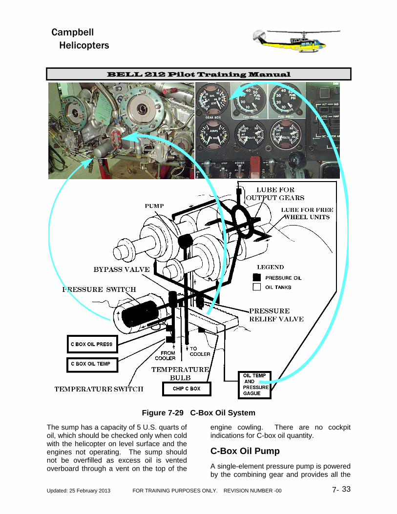
Figure 7-29 C-Box Oil System
The sump has a capacity of 5 U.S. quarts of oil, which should be checked only when cold with the helicopter on level surface and the engines not operating. The sump should not be overfilled as excess oil is vented overboard through a vent on the top of the
engine cowling. There are no cockpit indications for C-box oil quantity.
C-Box Oil Pump
A single-element pressure pump is powered by the combining gear and provides all the
BELL 212 Pilot Training Manual
UPDATED: 25 February 2013 TRAINING PURPOSES ONLY. REVISION NUMBER - 00 7-34
Campbell Helicopters
oil necessary for lubrication and cooling. Used oil drains back to the sump for reuse. There are no scavenging pumps.
C-Box Oil Filter
A single replaceable cartridge oil filter is located on the rear of the combining gearbox case. A by-pass valve is incorporated in the filter to prevent a clogged filter from interrupting oil flow. There is no cockpit indication of a clogged filter.
C-Box Oil Cooler
A thermostatically controlled C-box oil cooler is part of a three-cooler assembly mounted on top of the two-engine oil coolers at the rear of the powerplant. The C-box uses the lower 60 % of the third cooler assembly. Blowers driven by each engine's N2 gear reduction section provide cooling air for the engine oil coolers and the C-box cooler. (Figure 7-25). The thermostatic valve controls C-box oil cooling to ensure optimum oil temperature.
C-Box Oil System Operation When an engine is started and the N2 turbine wheel begins to turn the combining gear, the C-box oil pump starts to rotate. Oil is drawn from the sump and is pressurized by the pump. During the first engine start the pilot should check the C-box oil pressure gauge to ensure that oil pressure is starting to increase as N2 and Rotor RPM increase. (Figure 7-29).
Pressurized oil is directed through external lines to the C-box oil cooler, where the thermostatic valve opens a line to the cooler or bypasses the cooler, depending on the oil temperature. Cold oil is by-passed directly to the filter. Hot oil causes the thermostatic valve to direct the oil through the cooler before going to the filter.
Oil from the cooler passes through the filter mounted just left of center on the reduction gearbox. This filter is identical to the power section filter. In the filter, oil is cleansed of impurities. Should the filter become clogged, the spring-loaded closed by-pass valve can be forced open by oil pressure, allowing oil to by-pass the filter. An impending by-pass, red pop-out indicator on a differential pressure switch, is mounted on the upper left portion of the reduction gearbox. It extends at approximately 30 PSID.
There is no cockpit indication of a by-passed C-box oil filter. The pilot should check the C-box oil filter remote indicator during helicopter preflight.
Oil exiting the filter is directed through internal lines to a ball pressure relief valve, which regulates system pressure by venting excess pressure back to the sump.
Pressurized oil is directed through internal lines to provide lubrication and cooling for the clutch gear bearings and the combining gear bearings. Used oil drains back to the sump for reuse.
C-Box Oil Indicating Systems
The C-box oil system includes a temperature and pressure gauge, C-BOX OIL PRESS warning light, C-BOX OIL TEMP warning light, and CHIP C-BOX caution light (Figure 7-29).
C-Box Oil Pressure Gauge
A C-box oil pressure transmitter, located on the top of the C-box case directly above the main drive shaft output, senses oil pressure and displays it in psi on the C-box combined temperature and pressure gauge. The transmitter uses 26.5-VAC electrical power from the No.2 AC bus and is protected with the C-BOX OIL PRESS circuit breaker. Loss of No.2 AC power results in loss of oil pressure indications.
BELL 212 Pilot Training Manual
UPDATED: 25 February 2013 TRAINING PURPOSES ONLY. REVISION NUMBER - 00 7-35
Campbell Helicopters
C-Box Oil Temperature Gauge The C-box oil temperature bulb, located underneath the C-box behind the C-box oil filter, senses oil temperature and displays it in degrees centigrade on the C-box combined temperature and pressure gauge. The temperature bulb uses 28-VDC electrical power and is protected with the C-BOX OIL TEMP circuit breaker. Loss of electrical power results in loss of oil temperature indications.
C-BOX OIL PRESS Warning Light A normally closed oil pressure switch is located at the bottom of the C-box case near the oil filter. C-box oil pressure opens the pressure switch at 40 psi and extinguishes the C-BOX OIL PRESS warning light. If C-box oil pressure drops below 31 psi, the switch closes and illuminates the warning light. The switch uses 28 VDC through the MASTER CAUTION circuit breaker located on the overhead panel.
The 31-psi value at which the warning light illuminates is well below the system operation normal green minimum of 60 psi. Therefore, the pilot should not rely on the C-BOX OIL PRESS warning light as the primary indication of low C-box oil pressure.
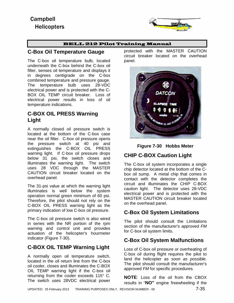
The C-box oil pressure switch is also wired in series with the NR portion of the rpm warning and control unit and provides actuation of the helicopter's hourmeter indicator (Figure 7-30).
C-BOX OIL TEMP Warning Light A normally open oil temperature switch, located in the oil return line from the C-box oil cooler, closes and illuminates the C-BOX OIL TEMP warning light if the C-box oil returning from the cooler exceeds 115° C. The switch uses 28VDC electrical power
protected with the MASTER CAUTION circuit breaker located on the overhead panel.
Figure 7-30 Hobbs Meter
CHIP C-BOX Caution Light The C-box oil system incorporates a single chip detector located at the bottom of the C-box oil sump. A metal chip that comes in contact with the detector completes the circuit and illuminates the CHIP C-BOX caution light. The detector uses 28-VDC electrical power and is protected with the MASTER CAUTION circuit breaker located on the overhead panel.
C-Box Oil System Limitations
The pilot should consult the Limitations section of the manufacturer's approved FM for C-box oil system limits.
C-Box Oil System Malfunctions
Loss of C-box oil pressure or overheating of C-box oil during flight requires the pilot to land the helicopter as soon as possible. The pilot should consult the manufacturer's approved FM for specific procedures.
NOTE: Loss of the oil from the CBOX results in “NO” engine freewheeling if the
BELL 212 Pilot Training Manual
UPDATED: 25 February 2013 TRAINING PURPOSES ONLY. REVISION NUMBER - 00 7-36
Campbell Helicopters
C-box seize, since the freewheeling unit has been removed from the transmission.
Illumination of the CHIP C-BOX caution light requires landing as soon as
practicable. The pilot should consult the manufacturer's approved FM for specific procedures.