Embed Size (px)
Citation preview
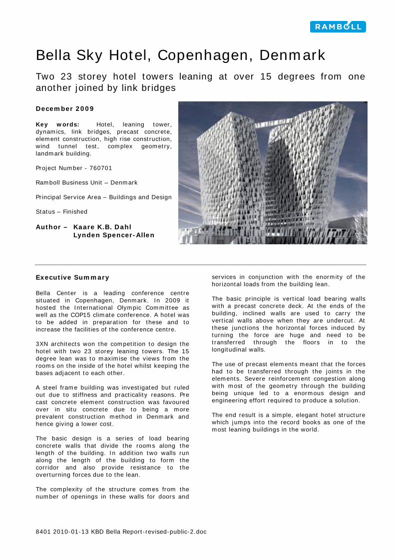
Bella Sky Hotel, Copenhagen, Denmark
Two 23 storey hotel towers leaning at over 15 degrees from one another joined by link bridges December 2009 Key words: Hotel, leaning tower, dynamics, link bridges, precast concrete, element construction, high rise construction, wind tunnel test, complex geometry, landmark building. Project Number - 760701 Ramboll Business Unit – Denmark Principal Service Area – Buildings and Design Status – Finished Author – Kaare K.B. Dahl Lynden Spencer-Allen Executive Summary Bella Center is a leading conference centre situated in Copenhagen, Denmark. In 2009 it hosted the International Olympic Committee as well as the COP15 climate conference. A hotel was to be added in preparation for these and to increase the facilities of the conference centre. 3XN architects won the competition to design the hotel with two 23 storey leaning towers. The 15 degree lean was to maximise the views from the rooms on the inside of the hotel whilst keeping the bases adjacent to each other. A steel frame building was investigated but ruled out due to stiffness and practicality reasons. Pre cast concrete element construction was favoured over in situ concrete due to being a more prevalent construction method in Denmark and hence giving a lower cost. The basic design is a series of load bearing concrete walls that divide the rooms along the length of the building. In addition two walls run along the length of the building to form the corridor and also provide resistance to the overturning forces due to the lean. The complexity of the structure comes from the number of openings in these walls for doors and
services in conjunction with the enormity of the horizontal loads from the building lean. The basic principle is vertical load bearing walls with a precast concrete deck. At the ends of the building, inclined walls are used to carry the vertical walls above when they are undercut. At these junctions the horizontal forces induced by turning the force are huge and need to be transferred through the floors in to the longitudinal walls. The use of precast elements meant that the forces had to be transferred through the joints in the elements. Severe reinforcement congestion along with most of the geometry through the building being unique led to a enormous design and engineering effort required to produce a solution. The end result is a simple, elegant hotel structure which jumps into the record books as one of the most leaning buildings in the world.
8401 2010-01-13 KBD Bella Report-revised-public-2.doc
Bella Hotel
Introduction The Bella Center is one of the leading conference centres in Europe. It is located on the outskirts of Copenhagen in Denmark. In order to accommodate its clients better, Bella Center wanted to create a hotel on the site of the conference centre. Rather than a simple hotel, Bella Center wanted an iconic building that would form an attraction in its own right thereby increasing the attraction of holding conferences there. In addition, hosting the International Olympic Committee and the COP15 conference in late 2009 gave the incentive to complete the building as soon as possible. However, a change in ownership at Bella Center meant delays to project funding which resulted in delivering the hotel in time for these events becoming impossible. The site of Bella Center is on the island of Amager which is to the south east of Copenhagen historic city centre. Bella Center first moved to the site in the early 1970s which at the time was largely un developed. In 1994 a development zone called Ørestad was initiated that created a zone 600m wide by 5000m long which encompassed the Bella Center. Ever since, new buildings and infrastructure have been built in the area, most recently accelerated by the completion of the Øresund bridge linking Denmark and Sweden which is close to the site. This is also the location of the new Ramboll Headquarters Building.
1. Location of site in relation to Copenhagen City Centre
Airport Flight Path Copenhagen airport is approximately 4km from the Bella Center. It is also aligned on the flight path of the north east runway which means it is in a zone of controlled development. In particular the height of the finished construction and any temporary works.
2. The site in relation to the airport Architecture The design of the new Bella Hotel was subject to an architectural competition in 2006. 3xNielsen (3XN) and Ramboll joined forces to enter with a striking but simple two tower structure.
3. 3XN Original Competition Entry Image 3XN’s design took the brief for the number of rooms and divided it between two tower structures. This was for a number of reasons: − To allow phased construction − Hotel rooms need to have a window and so
there is a maximum building width − The airport flight path limited the height of a
single building The building plot is limited in size, and the original plot furthermore called for a major road to cross
2
Bella Hotel
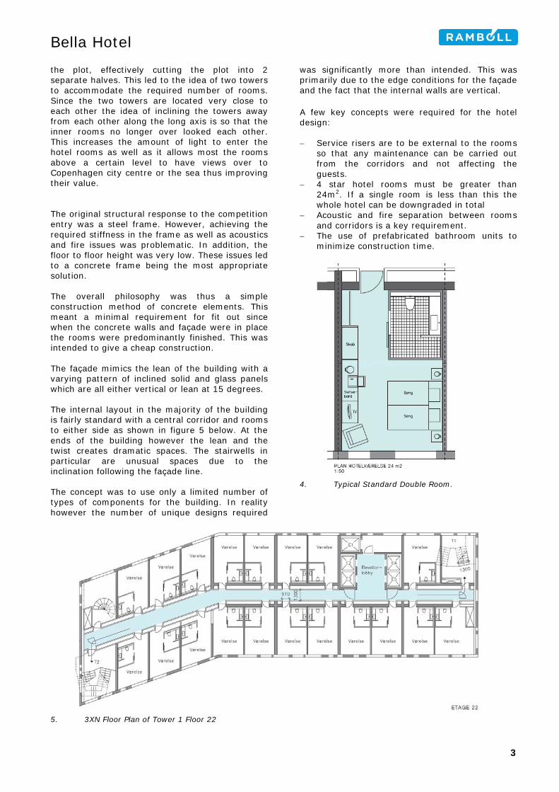
the plot, effectively cutting the plot into 2 separate halves. This led to the idea of two towers to accommodate the required number of rooms. Since the two towers are located very close to each other the idea of inclining the towers away from each other along the long axis is so that the inner rooms no longer over looked each other. This increases the amount of light to enter the hotel rooms as well as it allows most the rooms above a certain level to have views over to Copenhagen city centre or the sea thus improving their value. The original structural response to the competition entry was a steel frame. However, achieving the required stiffness in the frame as well as acoustics and fire issues was problematic. In addition, the floor to floor height was very low. These issues led to a concrete frame being the most appropriate solution. The overall philosophy was thus a simple construction method of concrete elements. This meant a minimal requirement for fit out since when the concrete walls and façade were in place the rooms were predominantly finished. This was intended to give a cheap construction. The façade mimics the lean of the building with a varying pattern of inclined solid and glass panels which are all either vertical or lean at 15 degrees. The internal layout in the majority of the building is fairly standard with a central corridor and rooms to either side as shown in figure 5 below. At the ends of the building however the lean and the twist creates dramatic spaces. The stairwells in particular are unusual spaces due to the inclination following the façade line. The concept was to use only a limited number of types of components for the building. In reality however the number of unique designs required
was significantly more than intended. This was primarily due to the edge conditions for the façade and the fact that the internal walls are vertical. A few key concepts were required for the hotel design: − Service risers are to be external to the rooms
so that any maintenance can be carried out from the corridors and not affecting the guests.
− 4 star hotel rooms must be greater than 24m2. If a single room is less than this the whole hotel can be downgraded in total
− Acoustic and fire separation between rooms and corridors is a key requirement.
− The use of prefabricated bathroom units to minimize construction time.
4. Typical Standard Double Room.
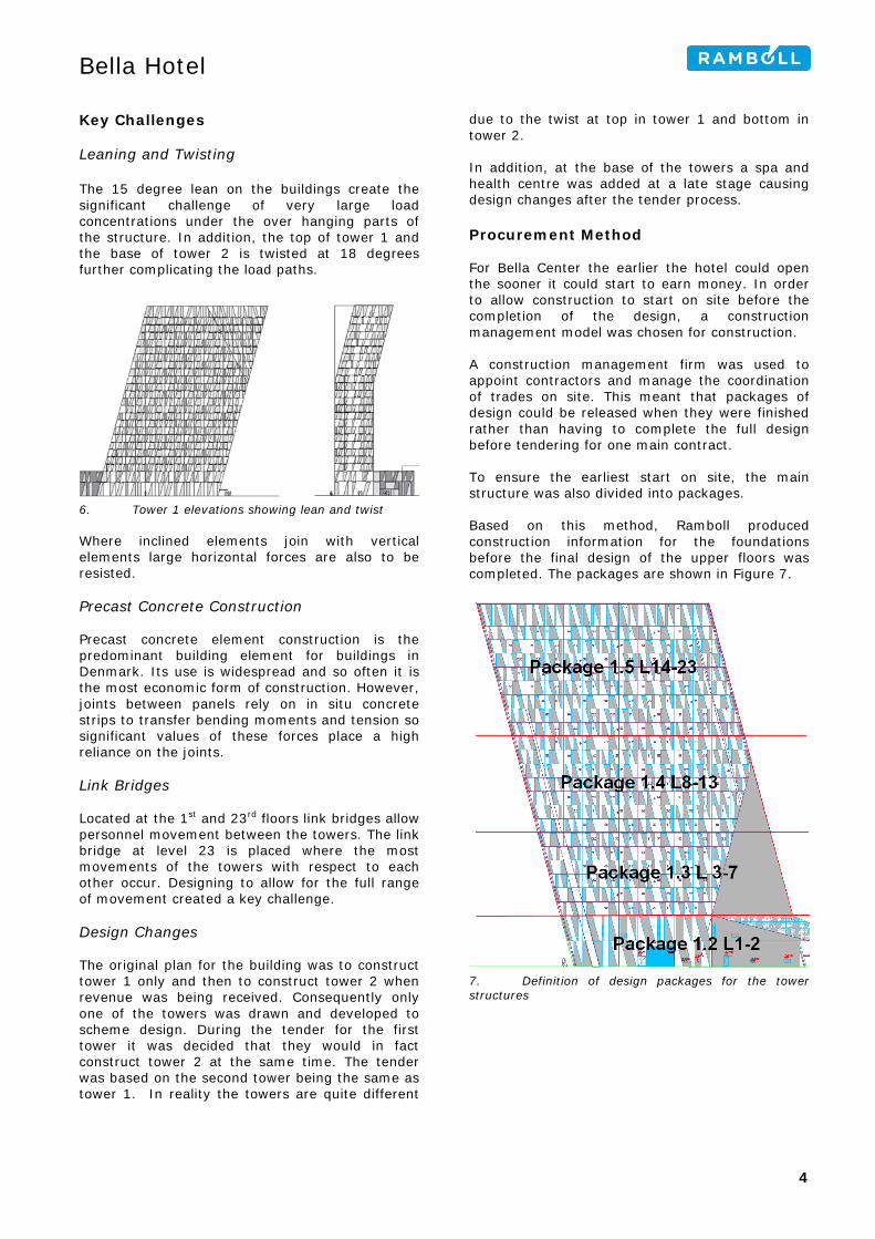
5. 3XN Floor Plan of Tower 1 Floor 22
3
Bella Hotel
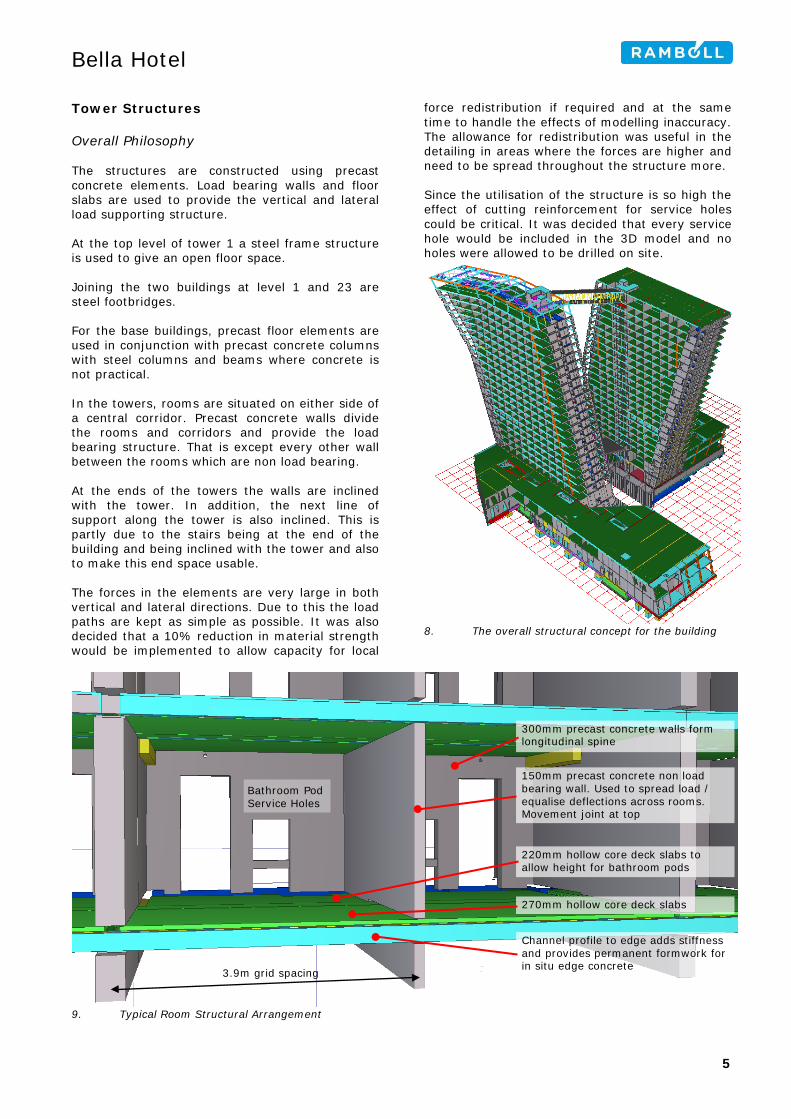
Key Challenges Leaning and Twisting The 15 degree lean on the buildings create the significant challenge of very large load concentrations under the over hanging parts of the structure. In addition, the top of tower 1 and the base of tower 2 is twisted at 18 degrees further complicating the load paths.
6. Tower 1 elevations showing lean and twist Where inclined elements join with vertical elements large horizontal forces are also to be resisted. Precast Concrete Construction Precast concrete element construction is the predominant building element for buildings in Denmark. Its use is widespread and so often it is the most economic form of construction. However, joints between panels rely on in situ concrete strips to transfer bending moments and tension so significant values of these forces place a high reliance on the joints. Link Bridges Located at the 1st and 23rd floors link bridges allow personnel movement between the towers. The link bridge at level 23 is placed where the most movements of the towers with respect to each other occur. Designing to allow for the full range of movement created a key challenge. Design Changes The original plan for the building was to construct tower 1 only and then to construct tower 2 when revenue was being received. Consequently only one of the towers was drawn and developed to scheme design. During the tender for the first tower it was decided that they would in fact construct tower 2 at the same time. The tender was based on the second tower being the same as tower 1. In reality the towers are quite different
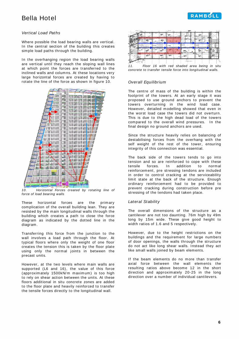
due to the twist at top in tower 1 and bottom in tower 2. In addition, at the base of the towers a spa and health centre was added at a late stage causing design changes after the tender process. Procurement Method For Bella Center the earlier the hotel could open the sooner it could start to earn money. In order to allow construction to start on site before the completion of the design, a construction management model was chosen for construction. A construction management firm was used to appoint contractors and manage the coordination of trades on site. This meant that packages of design could be released when they were finished rather than having to complete the full design before tendering for one main contract. To ensure the earliest start on site, the main structure was also divided into packages. Based on this method, Ramboll produced construction information for the foundations before the final design of the upper floors was completed. The packages are shown in Figure 7.
7. Definition of design packages for the tower structures
4
Bella Hotel
Tower Structures Overall Philosophy The structures are constructed using precast concrete elements. Load bearing walls and floor slabs are used to provide the vertical and lateral load supporting structure. At the top level of tower 1 a steel frame structure is used to give an open floor space. Joining the two buildings at level 1 and 23 are steel footbridges. For the base buildings, precast floor elements are used in conjunction with precast concrete columns with steel columns and beams where concrete is not practical. In the towers, rooms are situated on either side of a central corridor. Precast concrete walls divide the rooms and corridors and provide the load bearing structure. That is except every other wall between the rooms which are non load bearing. At the ends of the towers the walls are inclined with the tower. In addition, the next line of support along the tower is also inclined. This is partly due to the stairs being at the end of the building and being inclined with the tower and also to make this end space usable. The forces in the elements are very large in both vertical and lateral directions. Due to this the load paths are kept as simple as possible. It was also decided that a 10% reduction in material strength would be implemented to allow capacity for local
force redistribution if required and at the same time to handle the effects of modelling inaccuracy. The allowance for redistribution was useful in the detailing in areas where the forces are higher and need to be spread throughout the structure more. Since the utilisation of the structure is so high the effect of cutting reinforcement for service holes could be critical. It was decided that every service hole would be included in the 3D model and no holes were allowed to be drilled on site.
8. The overall structural concept for the building
9. Typical Room Structural Arrangement
270mm hollow core deck slabs
220mm hollow core deck slabs to allow height for bathroom pods
300mm precast concrete walls form longitudinal spine
150mm precast concrete non load bearing wall. Used to spread load / equalise deflections across rooms. Movement joint at top
Channel profile to edge adds stiffness and provides permanent formwork for in situ edge concrete
Bathroom Pod Service Holes
3.9m grid spacing
5
Bella Hotel
Vertical Load Paths Where possible the load bearing walls are vertical. In the central section of the building this creates simple load paths through the building. In the overhanging region the load bearing walls are vertical until they reach the sloping wall lines at which point the forces are transferred to the inclined walls and columns. At these locations very large horizontal forces are created by having to rotate the line of the force as shown in figure 10.
10. Horizontal Forces created by rotating line of force of load bearing walls These horizontal forces are the primary complication of the overall building lean. They are resisted by the main longitudinal walls through the building which creates a path to close the force diagram as indicated by the dotted line in the diagram. Transferring this force from the junction to the wall involves a load path through the floor. At typical floors where only the weight of one floor creates the tension this is taken by the floor plate using only the normal joints in between the precast units. However, at the two levels where main walls are supported (L6 and 16), the value of this force (approximately 1500kN/m maximum) is too high to rely on shear action between the units. At these floors additional in situ concrete zones are added to the floor plate and heavily reinforced to transfer the tensile forces directly to the longitudinal wall.
11. Floor 16 with red shaded area being in situ concrete to transfer tensile force into longitudinal walls. Overall Equilibrium The centre of mass of the building is within the footprint of the towers. At an early stage it was proposed to use ground anchors to prevent the towers overturning in the wind load case. However, detailed modelling showed that even in the worst load case the towers did not overturn. This is due to the high dead load of the towers compared to the overall wind pressures. In the final design no ground anchors are used. Since the structure heavily relies on balancing of destabilising forces from the overhang with the self weight of the rest of the tower, ensuring integrity of this connection was essential. The back side of the towers tends to go into tension and so are reinforced to cope with these tensile forces. In addition to normal reinforcement, pre stressing tendons are included in order to control cracking at the serviceability limit state at the back of the structure. Enough ordinary reinforcement had to be provided to prevent cracking during construction before pre stressing of the tendons had taken place. Lateral Stability The overall dimensions of the structure as a cantilever are not too daunting. 76m high by 49m long by 15m wide. These give good height to width ratios of 1.6 and 5 respectively. However, due to the height restrictions on the buildings and the requirement for large numbers of door openings, the walls through the structure do not act like long shear walls. Instead they act like small walls joined by beam elements. If the beam elements do no more than transfer axial force between the wall elements the resulting ratios above become 12 in the short direction and approximately 20-25 in the long direction over a number of individual cantilevers.
6
Bella Hotel
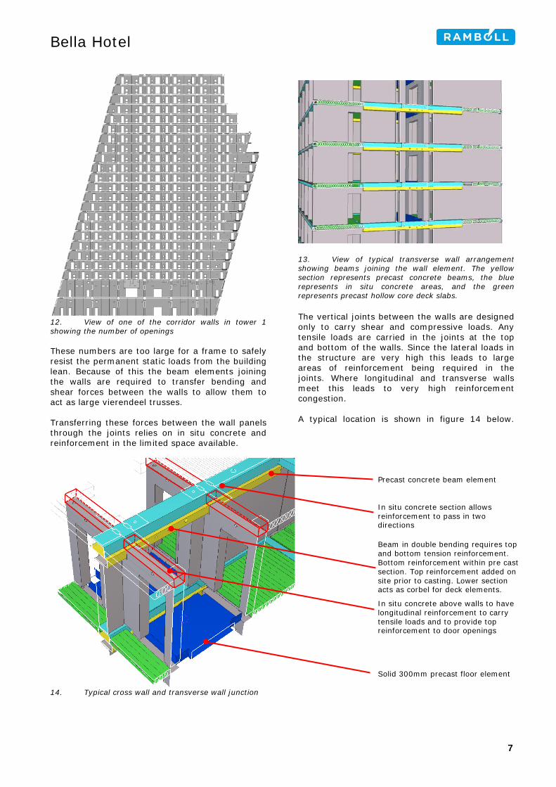
12. View of one of the corridor walls in tower 1 showing the number of openings These numbers are too large for a frame to safely resist the permanent static loads from the building lean. Because of this the beam elements joining the walls are required to transfer bending and shear forces between the walls to allow them to act as large vierendeel trusses. Transferring these forces between the wall panels through the joints relies on in situ concrete and reinforcement in the limited space available.
13. View of typical transverse wall arrangement showing beams joining the wall element. The yellow section represents precast concrete beams, the blue represents in situ concrete areas, and the green represents precast hollow core deck slabs. The vertical joints between the walls are designed only to carry shear and compressive loads. Any tensile loads are carried in the joints at the top and bottom of the walls. Since the lateral loads in the structure are very high this leads to large areas of reinforcement being required in the joints. Where longitudinal and transverse walls meet this leads to very high reinforcement congestion. A typical location is shown in figure 14 below.
14. Typical cross wall and transverse wall junction
In situ concrete above walls to have longitudinal reinforcement to carry tensile loads and to provide top reinforcement to door openings
Beam in double bending requires top and bottom tension reinforcement. Bottom reinforcement within pre cast section. Top reinforcement added on site prior to casting. Lower section acts as corbel for deck elements.
Precast concrete beam element
In situ concrete section allows reinforcement to pass in two directions
Solid 300mm precast floor element
7
Bella Hotel
Computer Modelling The software used to carry out the design of the towers was Robot Millenium along with in house design spreadsheet software.
15. Robot Model of Tower 2 Two separate Robot models were created for the towers. Shell elements were used to model the walls with panels created for the wall and floor elements. A significant consideration was that of the time taken to run the calculations on the models. How coarse the mesh was had a significant effect on the quality of the results but also the time taken to run the model. The use of Robot within Ramboll Denmark on concrete element construction was new and so a detailed analysis was undertaken to determine the best way to model the elements but also how to interpret the results.
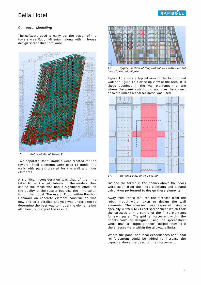
16. Typical section of longitudinal wall with element investigated highlighted Figure 16 shows a typical area of the longitudinal wall and figure 17 a close up view of the area. It is these openings in the wall elements that are where the panel cuts would not give the correct answers unless a coarser mesh was used.
17. Detailed view of wall portion Instead the forces in the beams above the doors were taken from the finite elements and a hand calculation performed to design these elements. Away from these features the stresses from the robot model were taken to design the wall elements. The stresses were exported using a specially written MS Excel spreadsheet which took the stresses at the centre of the finite elements for each panel. The grid reinforcement within the panels could be designed using the spreadsheet which gave a simple graphical output showing if the stresses were within the allowable limits. Where the panel had local exceedances additional reinforcement could be added to increase the capacity above the basic grid reinforcement.
8
Bella Hotel
18. Typical graphical output of wall panel element utilisation with supplied reinforcement. It became apparent that ground anchors would not be necessary to support the building since there was no net overturning force. However, sections of the foundation go into uplift to which the foundations do not provide restraint. In order to model this effectively a non linear foundation support would be required which would significantly increase the computing time required. In order to avoid non linear analysis a visual basic script was created which would identify any supports that had gone into tension and then remove them prior to the next iteration of the calculation model. At each stage of the process the supports on the model could be shown graphically. Figure 19 shows a graphical example of this.
19. Example showing the active supports in an iteration of the model after the script had removed some of the supports Even with the optimisation and restricting the model to a linear analysis running the two models took six computers two days to complete. This was made up of 13 load cases and 6-9 iterations each taking 2 hours each.
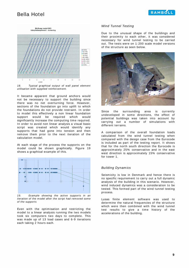
Wind Tunnel Testing Due to the unusual shape of the buildings and their proximity to each other, it was considered necessary for wind tunnel testing to be carried out. The tests were on 1:200 scale model versions of the structure as seen below.
Since the surrounding area is currently undeveloped in some directions, the effect of potential buildings was taken into account by carrying out a number of simulations with different terrains. A comparison of the overall foundation loads calculated from the wind tunnel testing when compared with the design case from the Eurocode is included as part of the testing report. It shows that for the north south direction the Eurocode is approximately 25% conservative and in the east west direction is approximately 15% conservative for tower 1. Building Dynamics Seismicity is low in Denmark and hence there is no specific requirement to carry out a full dynamic analysis of the building in this scenario. However, wind induced dynamics was a consideration to be tested. This formed part of the wind tunnel testing process. Lusas finite element software was used to determine the natural frequencies of the structure which were then combined with the wind tunnel test results to give a time history of the accelerations of the building.
9
Bella Hotel
20. Mode 1 (0,46Hz) and Mode 2 (0,98Hz) of the structure The accelerations were compared with recommendations in ISO 10137 Bases for the design of structures – serviceability of buildings and walkways against vibrations. This gives maximum values for residential and office areas to be assessed in the one year return period. The analysis showed that some areas of the building exceeded the recommended maximum accelerations as shown in the figure below for the first two mode shapes.
21. Areas of building not complying with serviceability limit state acceleration limits. Single hatch represents residential limit and double hatch office usage. The use of a tuned mass damper to reduce the effects was considered to counteract the wind effects. However the size of these meant the cost was prohibitive within the scheme. Instead a management approach would be taken whereby the hotel could compensate any guests adversely affected on an individual basis. Robustness In Denmark for buildings in the High Consequence Class (CC3) there are two primary options for providing robustness: − Carrying out an element removal analysis
− Ensuring each connection has sufficient redundancy – by reducing the allowable utilisation ratios of the elements for example.
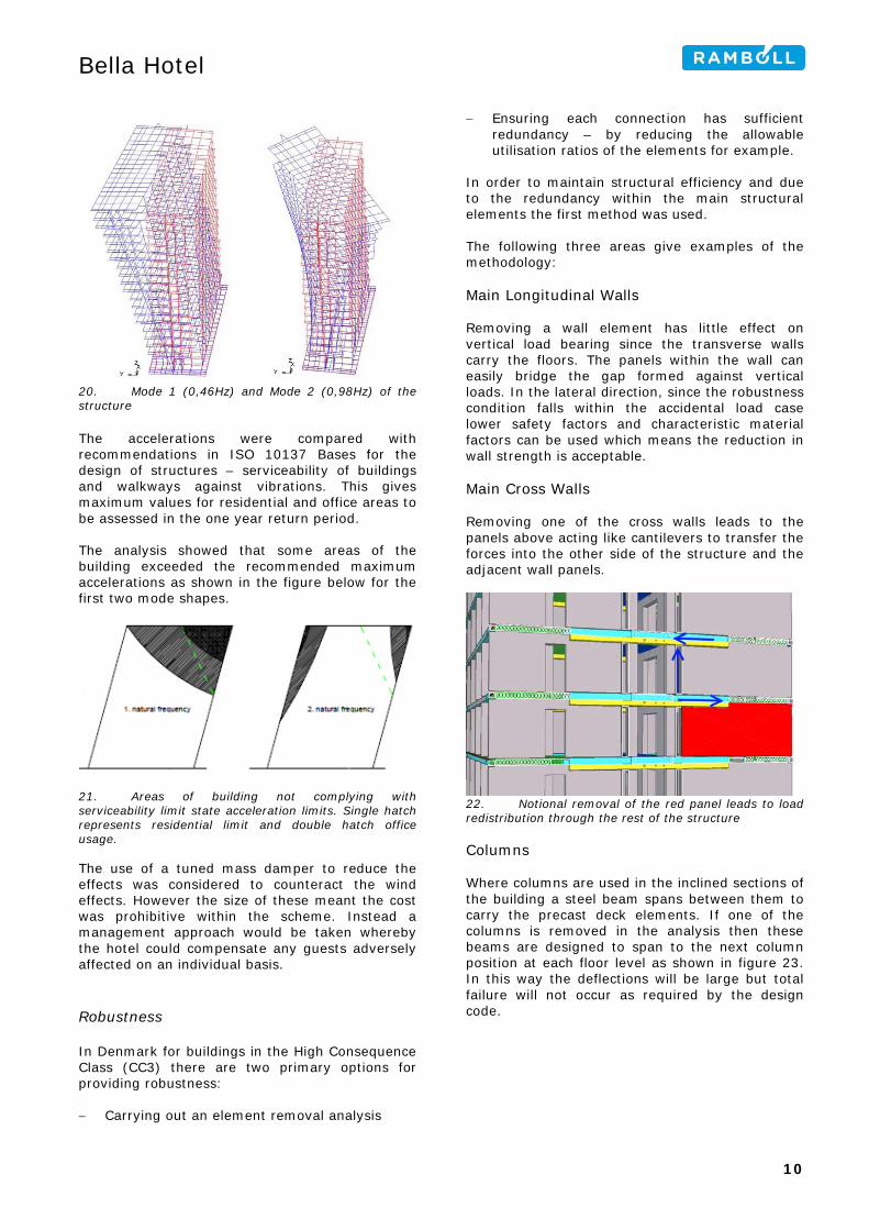
In order to maintain structural efficiency and due to the redundancy within the main structural elements the first method was used. The following three areas give examples of the methodology: Main Longitudinal Walls Removing a wall element has little effect on vertical load bearing since the transverse walls carry the floors. The panels within the wall can easily bridge the gap formed against vertical loads. In the lateral direction, since the robustness condition falls within the accidental load case lower safety factors and characteristic material factors can be used which means the reduction in wall strength is acceptable. Main Cross Walls Removing one of the cross walls leads to the panels above acting like cantilevers to transfer the forces into the other side of the structure and the adjacent wall panels.
22. Notional removal of the red panel leads to load redistribution through the rest of the structure Columns Where columns are used in the inclined sections of the building a steel beam spans between them to carry the precast deck elements. If one of the columns is removed in the analysis then these beams are designed to span to the next column position at each floor level as shown in figure 23. In this way the deflections will be large but total failure will not occur as required by the design code.
10
Bella Hotel
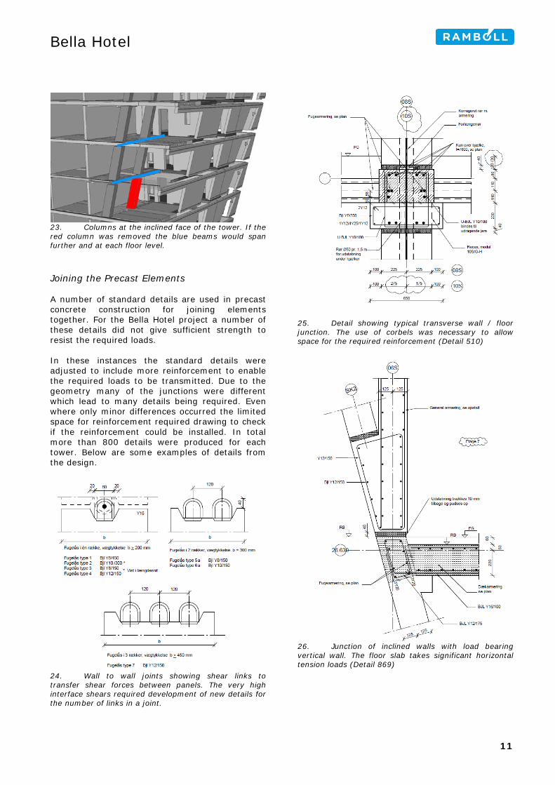
23. Columns at the inclined face of the tower. If the red column was removed the blue beams would span further and at each floor level. Joining the Precast Elements A number of standard details are used in precast concrete construction for joining elements together. For the Bella Hotel project a number of these details did not give sufficient strength to resist the required loads. In these instances the standard details were adjusted to include more reinforcement to enable the required loads to be transmitted. Due to the geometry many of the junctions were different which lead to many details being required. Even where only minor differences occurred the limited space for reinforcement required drawing to check if the reinforcement could be installed. In total more than 800 details were produced for each tower. Below are some examples of details from the design.
24. Wall to wall joints showing shear links to transfer shear forces between panels. The very high interface shears required development of new details for the number of links in a joint.
25. Detail showing typical transverse wall / floor junction. The use of corbels was necessary to allow space for the required reinforcement (Detail 510)
26. Junction of inclined walls with load bearing vertical wall. The floor slab takes significant horizontal tension loads (Detail 869)
11
Bella Hotel
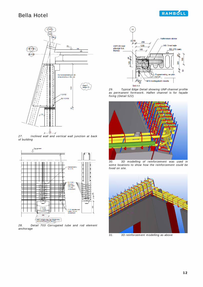
27. Inclined wall and vertical wall junction at back of building
28. Detail 703 Corrugated tube and rod element anchorage
29. Typical Edge Detail showing UNP channel profile as permanent formwork. Halfen channel is for façade fixing (Detail 522)
30. 3D modelling of reinforcement was used in some locations to show how the reinforcement could be fixed on site.
31. 3D reinforcement modelling as above
12
Bella Hotel
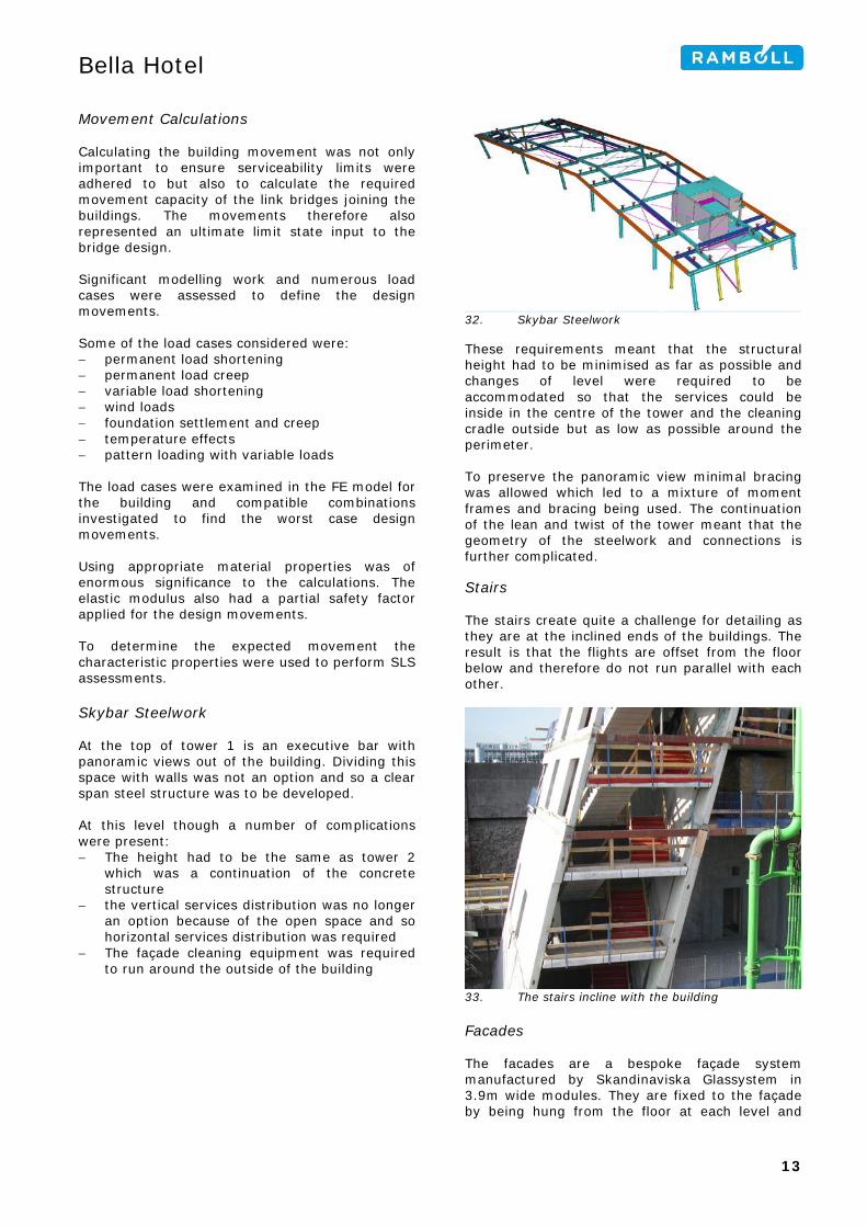
Movement Calculations Calculating the building movement was not only important to ensure serviceability limits were adhered to but also to calculate the required movement capacity of the link bridges joining the buildings. The movements therefore also represented an ultimate limit state input to the bridge design. Significant modelling work and numerous load cases were assessed to define the design movements. Some of the load cases considered were: − permanent load shortening − permanent load creep − variable load shortening − wind loads − foundation settlement and creep − temperature effects − pattern loading with variable loads The load cases were examined in the FE model for the building and compatible combinations investigated to find the worst case design movements. Using appropriate material properties was of enormous significance to the calculations. The elastic modulus also had a partial safety factor applied for the design movements. To determine the expected movement the characteristic properties were used to perform SLS assessments. Skybar Steelwork At the top of tower 1 is an executive bar with panoramic views out of the building. Dividing this space with walls was not an option and so a clear span steel structure was to be developed. At this level though a number of complications were present: − The height had to be the same as tower 2
which was a continuation of the concrete structure
− the vertical services distribution was no longer an option because of the open space and so horizontal services distribution was required
− The façade cleaning equipment was required to run around the outside of the building
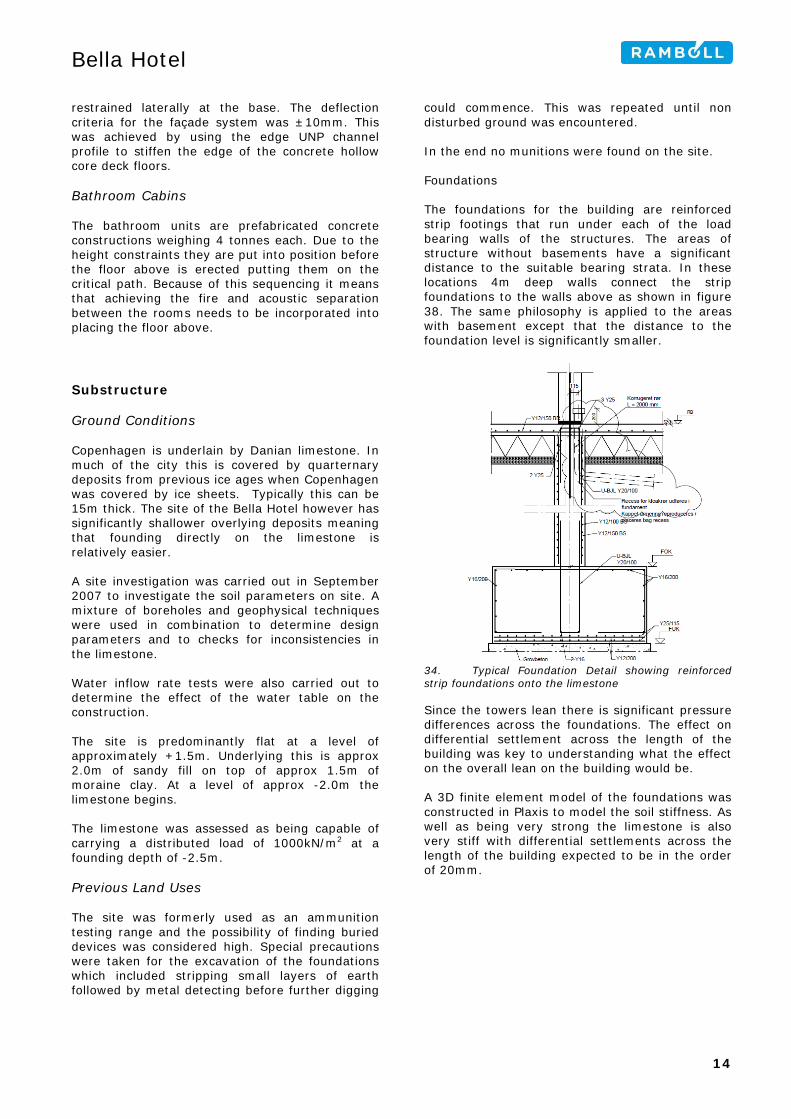
32. Skybar Steelwork These requirements meant that the structural height had to be minimised as far as possible and changes of level were required to be accommodated so that the services could be inside in the centre of the tower and the cleaning cradle outside but as low as possible around the perimeter. To preserve the panoramic view minimal bracing was allowed which led to a mixture of moment frames and bracing being used. The continuation of the lean and twist of the tower meant that the geometry of the steelwork and connections is further complicated. Stairs The stairs create quite a challenge for detailing as they are at the inclined ends of the buildings. The result is that the flights are offset from the floor below and therefore do not run parallel with each other.
33. The stairs incline with the building Facades The facades are a bespoke façade system manufactured by Skandinaviska Glassystem in 3.9m wide modules. They are fixed to the façade by being hung from the floor at each level and
13
Bella Hotel
restrained laterally at the base. The deflection criteria for the façade system was ±10mm. This was achieved by using the edge UNP channel profile to stiffen the edge of the concrete hollow core deck floors. Bathroom Cabins The bathroom units are prefabricated concrete constructions weighing 4 tonnes each. Due to the height constraints they are put into position before the floor above is erected putting them on the critical path. Because of this sequencing it means that achieving the fire and acoustic separation between the rooms needs to be incorporated into placing the floor above. Substructure Ground Conditions Copenhagen is underlain by Danian limestone. In much of the city this is covered by quarternary deposits from previous ice ages when Copenhagen was covered by ice sheets. Typically this can be 15m thick. The site of the Bella Hotel however has significantly shallower overlying deposits meaning that founding directly on the limestone is relatively easier. A site investigation was carried out in September 2007 to investigate the soil parameters on site. A mixture of boreholes and geophysical techniques were used in combination to determine design parameters and to checks for inconsistencies in the limestone. Water inflow rate tests were also carried out to determine the effect of the water table on the construction. The site is predominantly flat at a level of approximately +1.5m. Underlying this is approx 2.0m of sandy fill on top of approx 1.5m of moraine clay. At a level of approx -2.0m the limestone begins. The limestone was assessed as being capable of carrying a distributed load of 1000kN/m2 at a founding depth of -2.5m. Previous Land Uses The site was formerly used as an ammunition testing range and the possibility of finding buried devices was considered high. Special precautions were taken for the excavation of the foundations which included stripping small layers of earth followed by metal detecting before further digging
could commence. This was repeated until non disturbed ground was encountered. In the end no munitions were found on the site. Foundations The foundations for the building are reinforced strip footings that run under each of the load bearing walls of the structures. The areas of structure without basements have a significant distance to the suitable bearing strata. In these locations 4m deep walls connect the strip foundations to the walls above as shown in figure 38. The same philosophy is applied to the areas with basement except that the distance to the foundation level is significantly smaller.
34. Typical Foundation Detail showing reinforced strip foundations onto the limestone Since the towers lean there is significant pressure differences across the foundations. The effect on differential settlement across the length of the building was key to understanding what the effect on the overall lean on the building would be. A 3D finite element model of the foundations was constructed in Plaxis to model the soil stiffness. As well as being very strong the limestone is also very stiff with differential settlements across the length of the building expected to be in the order of 20mm.
14
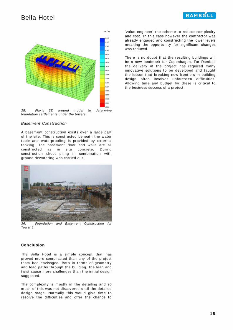
Bella Hotel
35. Plaxis 3D ground model to determine foundation settlements under the towers Basement Construction A basement construction exists over a large part of the site. This is constructed beneath the water table and waterproofing is provided by external tanking. The basement floor and walls are all constructed as in situ concrete. During construction sheet piling in combination with ground dewatering was carried out.
36. Foundation and Basement Construction for Tower 1 Conclusion The Bella Hotel is a simple concept that has proved more complicated than any of the project team had envisaged. Both in terms of geometry and load paths through the building, the lean and twist cause more challenges than the initial design suggested. The complexity is mostly in the detailing and so much of this was not discovered until the detailed design stage. Normally this would give time to resolve the difficulties and offer the chance to
'value engineer' the scheme to reduce complexity and cost. In this case however the contractor was already engaged and constructing the lower levels meaning the opportunity for significant changes was reduced. There is no doubt that the resulting buildings will be a new landmark for Copenhagen. For Ramboll the delivery of the project has required many innovative solutions to be developed and taught the lesson that breaking new frontiers in building design often involves unforeseen difficulties. Allowing time and budget for these is critical to the business success of a project.
15
Bella Hotel
Overall Programme Design Competition Outline Design (dispositionforslag)
April 2007
Scheme Design (projektforslag)
April 2008
Construction Tender June 2008 Detailed Design (hovedprojekt) Package 1.1 Package 1.2 Package 1.3 Package 1.4 Package 1.5 Package 2.1 Package 2.2 Package 2.3 Package 2.4 Package 2.5
August 2008 October 2008 November 2008 April 2009 August 2009 October 2008 December 2008 February 2009 May 2009 October 2009
Start of Construction August 2008 Start of Tower Construction
April 2009
Structural Completion December 2010 Hotel Opening Tower 1: May 2011
Tower 2: August 2011 Ramboll Team Project Manager Kaare K.B. Dahl Structures – Concrete Towers
Niels Jørgen Holm Mogens Bryndum Mette Ledgaard-Sørensen Kåre Flindt Jørgensen Martin Munck Tim Gudmand-Høyer Ted Weicker
Structures – Base Structure
Klaus Ås Hansen Christian Wolf
Structures – Skybar Steelwork and Link Bridges
Henrik Kortemann Hansen Bent Bonnerup Lynden Spencer-Allen Rasmus Palm Vestergård
Below ground drainage Henrik Møller Andersen Geotechnical Jacob Holte Construction Monitoring and Quantity Management
Peter Lund Christensen Thomas Jantzen Tim Andersen Bjørn Dannemare Lene Poder Westh Thorunn Sigurdardottir Hanne Eiland Morten Hasselriis
Drawing coordinator Morten Alsdorf 3D Modelling / CAD Grete Hørup Mogensen
Ajmal Poya Kirsten Sølling Bora Fuzuli Gøksu Abdelkader Boutaiba Carolina Farias De Brito
Facts and Figures Overall Number of Rooms 814 Floor Area 44,173 m2 Angle of lean Maximum inclination angle (9 top stories)
15.05 degrees 20.4 degrees
Height of Building 76.5m Dimensions on Plan 15.5m x 49m Overhang from base of building 20.57m Sideways overhang of building 7.96m Total Number of Design Hours 50.000 hours Concrete Structure In situ concrete volume 7200m3 (approx) Precast concrete volume 13000m3 Number of precast concrete elements
7100
Number of prefab. Steel edge beams
500
Number of prefab reinforcement cages for joint reinforcement
500
Heaviest precast concrete element
15000kg
Project Information Project Value 1.6 Billion DKK
16


![Untitled-1 [img.staticmb.com] · THE WORLD WITHIN YOUR REACH HOTELS Hotel Radisson Blu I Hotel Jaipur Marriott I Hotel Bella Casa I Hotel Clarks Amer I Hotel The Lalit HOSPITALS](https://img.pdfslide.net/doc/110x75/5af8ed317f8b9abd588c2f8a/untitled-1-img-world-within-your-reach-hotels-hotel-radisson-blu-i-hotel-jaipur.jpg)