Embed Size (px)
Citation preview
Benchmarking of Competitive Technologies
Tim Burress Oak Ridge National Laboratory
May 15, 2012
Project ID: APE006
This presentation does not contain any proprietary, confidential, or otherwise restricted information
2012 U.S. DOE Hydrogen and Fuel Cells Program and Vehicle Technologies Program Annual Merit Review and Peer Evaluation Meeting
Washington, D.C.
Managed by UT-Battelle for the U.S. Department of Energy 2
Overview
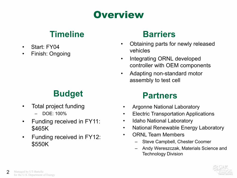
• Start: FY04 • Finish: Ongoing
• Obtaining parts for newly released vehicles
• Integrating ORNL developed controller with OEM components
• Adapting non-standard motor assembly to test cell
• Total project funding – DOE: 100%
• Funding received in FY11: $465K
• Funding received in FY12: $550K
Timeline
Budget
Barriers
• Argonne National Laboratory • Electric Transportation Applications • Idaho National Laboratory • National Renewable Energy Laboratory • ORNL Team Members
– Steve Campbell, Chester Coomer – Andy Wereszczak, Materials Science and
Technology Division
Partners
Managed by UT-Battelle for the U.S. Department of Energy 3
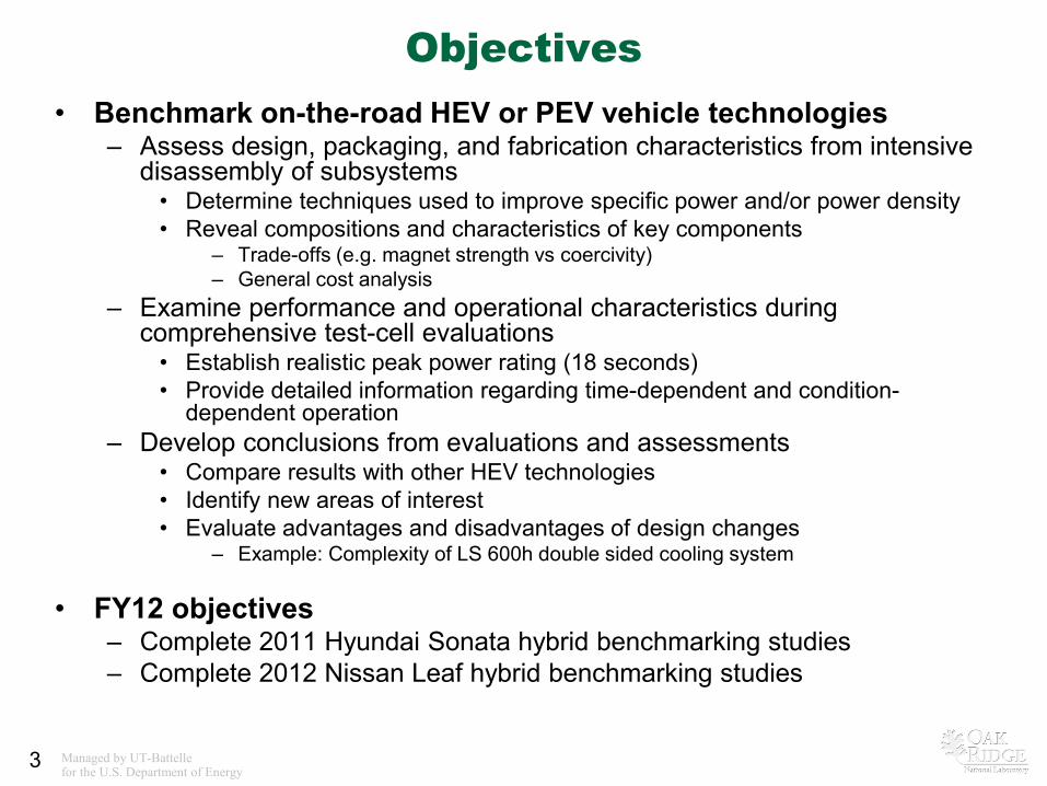
Objectives • Benchmark on-the-road HEV or PEV vehicle technologies
– Assess design, packaging, and fabrication characteristics from intensive disassembly of subsystems • Determine techniques used to improve specific power and/or power density • Reveal compositions and characteristics of key components
– Trade-offs (e.g. magnet strength vs coercivity) – General cost analysis
– Examine performance and operational characteristics during comprehensive test-cell evaluations • Establish realistic peak power rating (18 seconds) • Provide detailed information regarding time-dependent and condition-
dependent operation – Develop conclusions from evaluations and assessments
• Compare results with other HEV technologies • Identify new areas of interest • Evaluate advantages and disadvantages of design changes
– Example: Complexity of LS 600h double sided cooling system
• FY12 objectives – Complete 2011 Hyundai Sonata hybrid benchmarking studies – Complete 2012 Nissan Leaf hybrid benchmarking studies
Managed by UT-Battelle for the U.S. Department of Energy 4
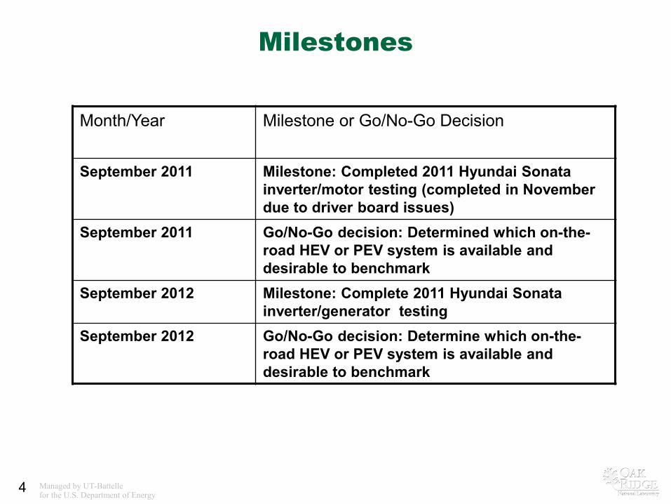
Milestones
Month/Year Milestone or Go/No-Go Decision
September 2011 Milestone: Completed 2011 Hyundai Sonata inverter/motor testing (completed in November due to driver board issues)
September 2011 Go/No-Go decision: Determined which on-the-road HEV or PEV system is available and desirable to benchmark
September 2012 Milestone: Complete 2011 Hyundai Sonata inverter/generator testing
September 2012 Go/No-Go decision: Determine which on-the-road HEV or PEV system is available and desirable to benchmark
Managed by UT-Battelle for the U.S. Department of Energy 5
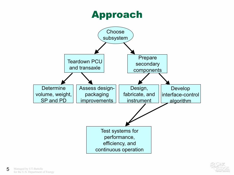
Approach Choose
subsystem
Teardown PCU and transaxle
Prepare secondary
components
Determine volume, weight,
SP and PD
Assess design-packaging
improvements
Design, fabricate, and
instrument
Develop interface-control
algorithm
Test systems for performance, efficiency, and
continuous operation
Managed by UT-Battelle for the U.S. Department of Energy
6
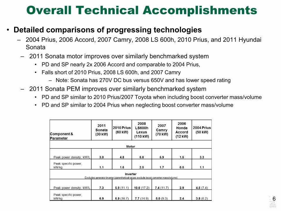
Overall Technical Accomplishments • Detailed comparisons of progressing technologies
– 2004 Prius, 2006 Accord, 2007 Camry, 2008 LS 600h, 2010 Prius, and 2011 Hyundai Sonata
– 2011 Sonata motor improves over similarly benchmarked system • PD and SP nearly 2x 2006 Accord and comparable to 2004 Prius, • Falls short of 2010 Prius, 2008 LS 600h, and 2007 Camry
– Note: Sonata has 270V DC bus versus 650V and has lower speed rating – 2011 Sonata PEM improves over similarly benchmarked system
• PD and SP similar to 2010 Prius/2007 Toyota when including boost converter mass/volume • PD and SP similar to 2004 Prius when neglecting boost converter mass/volume
Managed by UT-Battelle for the U.S. Department of Energy
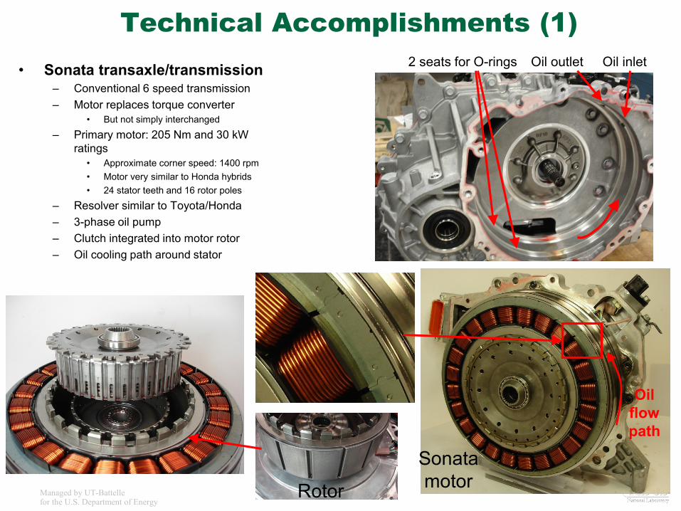
Technical Accomplishments (1) • Sonata transaxle/transmission
– Conventional 6 speed transmission – Motor replaces torque converter
• But not simply interchanged
– Primary motor: 205 Nm and 30 kW ratings
• Approximate corner speed: 1400 rpm • Motor very similar to Honda hybrids • 24 stator teeth and 16 rotor poles
– Resolver similar to Toyota/Honda – 3-phase oil pump – Clutch integrated into motor rotor – Oil cooling path around stator
Rotor
Sonata motor
2 seats for O-rings Oil outlet Oil inlet
Oil flow path
Managed by UT-Battelle for the U.S. Department of Energy
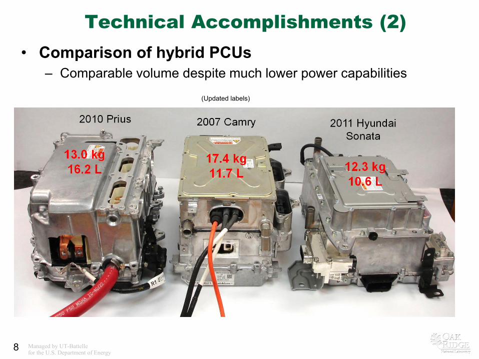
• Comparison of hybrid PCUs – Comparable volume despite much lower power capabilities
8
(Updated labels)
Technical Accomplishments (2)
Managed by UT-Battelle for the U.S. Department of Energy
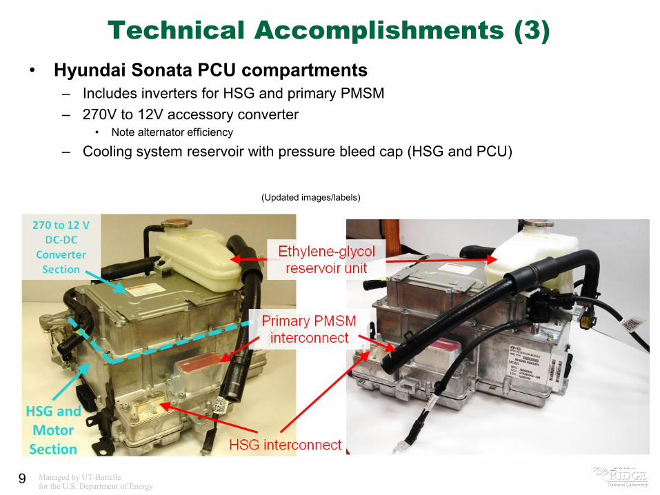
Technical Accomplishments (3) • Hyundai Sonata PCU compartments
– Includes inverters for HSG and primary PMSM – 270V to 12V accessory converter
• Note alternator efficiency
– Cooling system reservoir with pressure bleed cap (HSG and PCU)
9
(Updated images/labels)
Managed by UT-Battelle for the U.S. Department of Energy
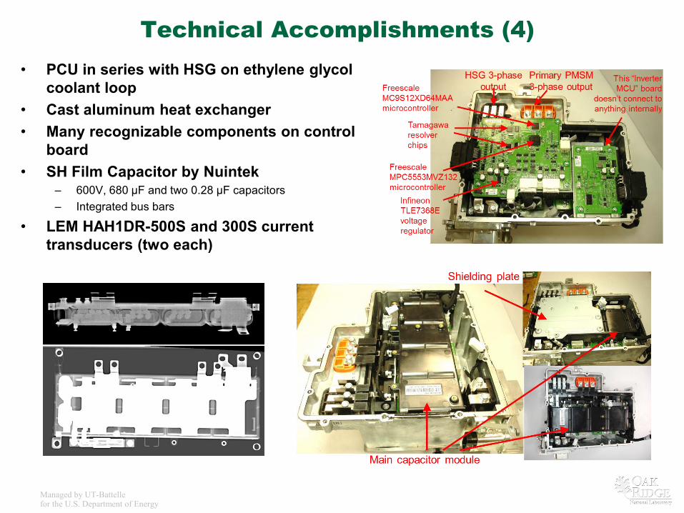
Technical Accomplishments (4) • PCU in series with HSG on ethylene glycol
coolant loop • Cast aluminum heat exchanger • Many recognizable components on control
board • SH Film Capacitor by Nuintek
– 600V, 680 µF and two 0.28 µF capacitors – Integrated bus bars
• LEM HAH1DR-500S and 300S current transducers (two each)
Managed by UT-Battelle for the U.S. Department of Energy
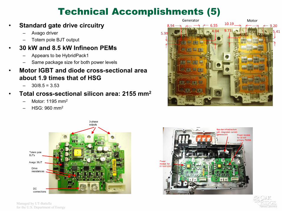
Technical Accomplishments (5) • Standard gate drive circuitry
– Avago driver – Totem pole BJT output
• 30 kW and 8.5 kW Infineon PEMs – Appears to be HybridPack1 – Same package size for both power levels
• Motor IGBT and diode cross-sectional area about 1.9 times that of HSG
– 30/8.5 = 3.53
• Total cross-sectional silicon area: 2155 mm2
– Motor: 1195 mm2 – HSG: 960 mm2
Managed by UT-Battelle for the U.S. Department of Energy
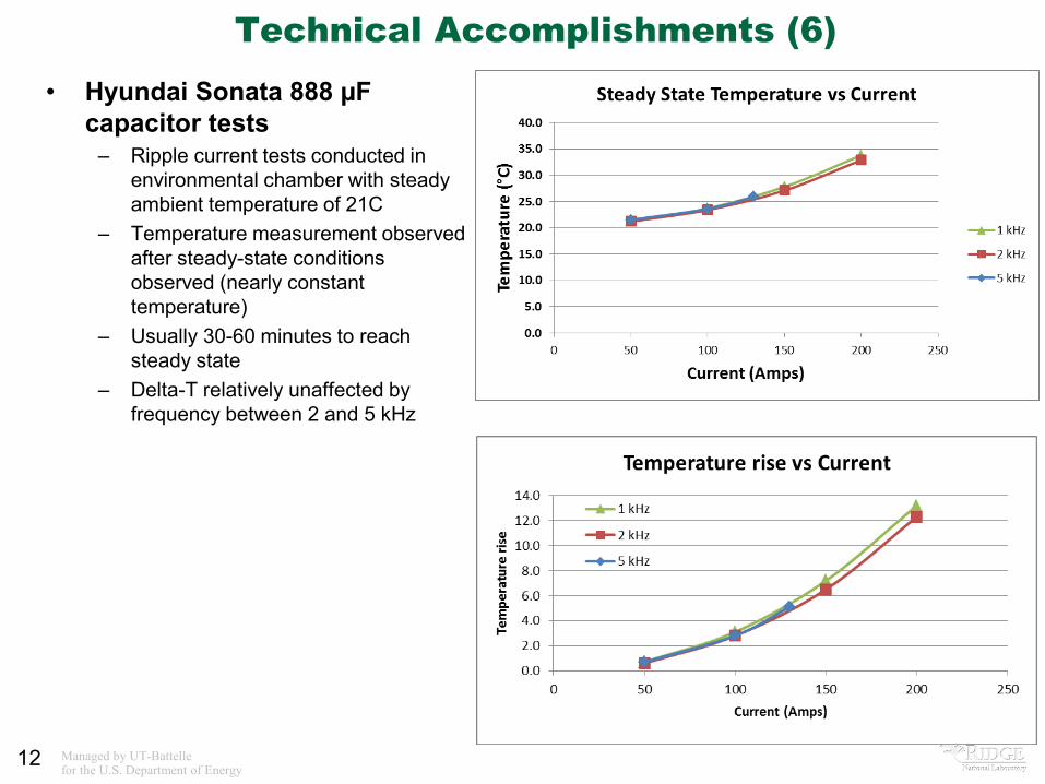
Technical Accomplishments (6) • Hyundai Sonata 888 µF
capacitor tests – Ripple current tests conducted in
environmental chamber with steady ambient temperature of 21C
– Temperature measurement observed after steady-state conditions observed (nearly constant temperature)
– Usually 30-60 minutes to reach steady state
– Delta-T relatively unaffected by frequency between 2 and 5 kHz
12
Managed by UT-Battelle for the U.S. Department of Energy
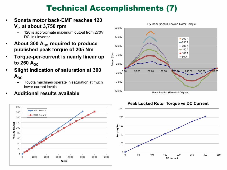
Technical Accomplishments (7) • Sonata motor back-EMF reaches 120
Vln at about 3,750 rpm – 120 is approximate maximum output from 270V
DC link inverter
• About 300 ADC required to produce published peak torque of 205 Nm
• Torque-per-current is nearly linear up to 250 ADC
• Slight indication of saturation at 300 ADC
– Toyota machines operate in saturation at much lower current levels
• Additional results available
Managed by UT-Battelle for the U.S. Department of Energy
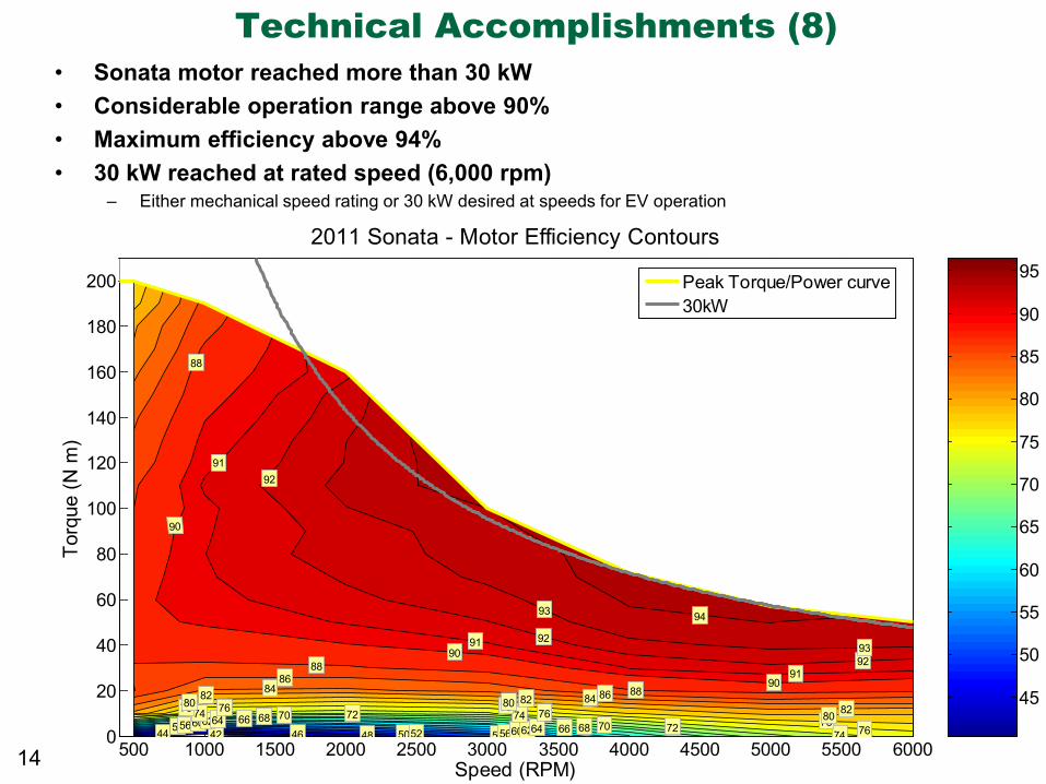
Technical Accomplishments (8) • Sonata motor reached more than 30 kW • Considerable operation range above 90% • Maximum efficiency above 94% • 30 kW reached at rated speed (6,000 rpm)
– Either mechanical speed rating or 30 kW desired at speeds for EV operation
14 500 1000 1500 2000 2500 3000 3500 4000 4500 5000 5500 60000
20
40
60
80
100
120
140
160
180
200
Speed (RPM)
Torq
ue (N
m)
2011 Sonata - Motor Efficiency Contours
4244 46 48 5052 5454 56
5658
5860
6062
6264
6466
6668
6870
7072
72
74
747476
767678
787880
8080 828282 84
84 8686
88
88
8890
90
90
91
91
91
92
92
92
93
93
93
94
94
95
95
96
96
97
97
45
50
55
60
65
70
75
80
85
90
95Peak Torque/Power curve30kW
Managed by UT-Battelle for the U.S. Department of Energy
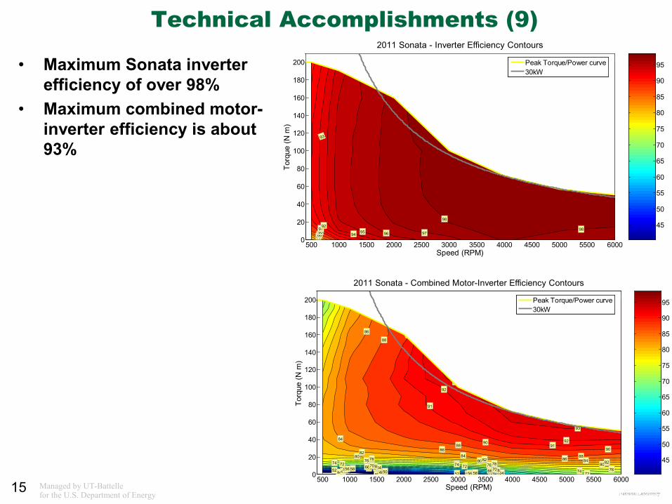
Technical Accomplishments (9)
• Maximum Sonata inverter efficiency of over 98%
• Maximum combined motor-inverter efficiency is about 93%
15
500 1000 1500 2000 2500 3000 3500 4000 4500 5000 5500 60000
20
40
60
80
100
120
140
160
180
200
Speed (RPM)
Torq
ue (N
m)
2011 Sonata - Inverter Efficiency Contours
86889091
92
93
94 95 96 9798
98
99
99
45
50
55
60
65
70
75
80
85
90
95Peak Torque/Power curve30kW
500 1000 1500 2000 2500 3000 3500 4000 4500 5000 5500 60000
20
40
60
80
100
120
140
160
180
200
Speed (RPM)
Torq
ue (N
m)
2011 Sonata - Combined Motor-Inverter Efficiency Contours
40424446 4850 5252
5454
5656
5858
6060
6262
6464
6666
6868
7070
72
7272
747474
7676
7678
7880
8080
8282
82
8484
84
86
86
86
88
88
88
9090
90
91
91
92
92
93
93
94
94
95
95
96
96
97
97
98
98
99
99
45
50
55
60
65
70
75
80
85
90
95Peak Torque/Power curve30kW
Managed by UT-Battelle for the U.S. Department of Energy
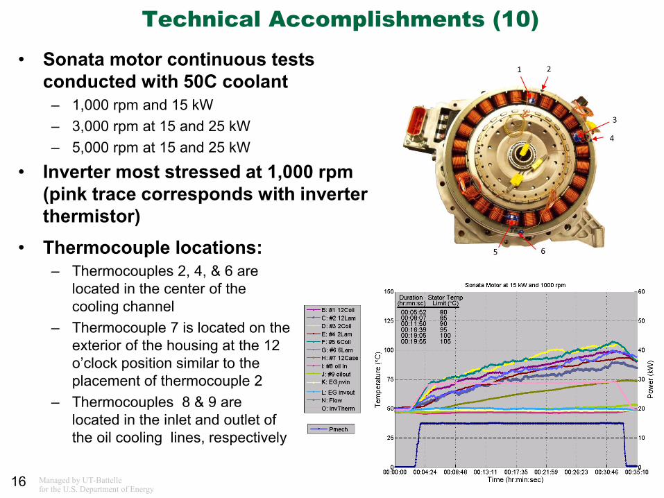
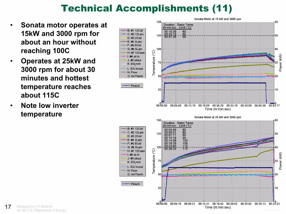
Technical Accomplishments (10)
• Sonata motor continuous tests conducted with 50C coolant
– 1,000 rpm and 15 kW – 3,000 rpm at 15 and 25 kW – 5,000 rpm at 15 and 25 kW
• Inverter most stressed at 1,000 rpm (pink trace corresponds with inverter thermistor)
16
• Thermocouple locations: – Thermocouples 2, 4, & 6 are
located in the center of the cooling channel
– Thermocouple 7 is located on the exterior of the housing at the 12 o’clock position similar to the placement of thermocouple 2
– Thermocouples 8 & 9 are located in the inlet and outlet of the oil cooling lines, respectively
Managed by UT-Battelle for the U.S. Department of Energy
Technical Accomplishments (11) • Sonata motor operates at
15kW and 3000 rpm for about an hour without reaching 100C
• Operates at 25kW and 3000 rpm for about 30 minutes and hottest temperature reaches about 115C
• Note low inverter temperature
17
Managed by UT-Battelle for the U.S. Department of Energy
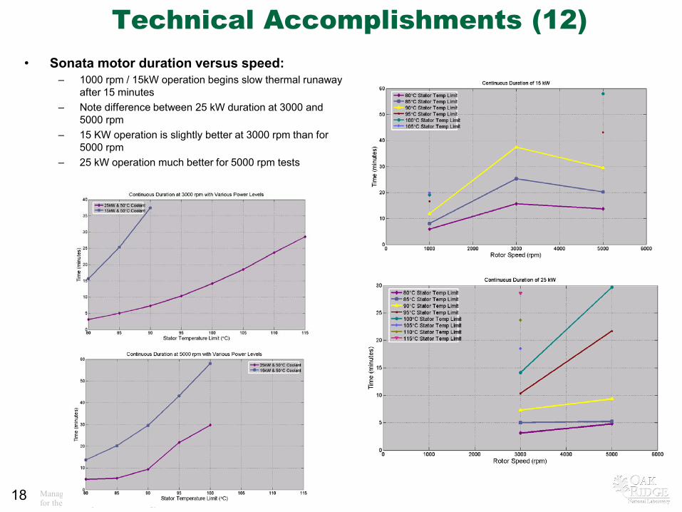
Technical Accomplishments (12) • Sonata motor duration versus speed:
– 1000 rpm / 15kW operation begins slow thermal runaway after 15 minutes
– Note difference between 25 kW duration at 3000 and 5000 rpm
– 15 KW operation is slightly better at 3000 rpm than for 5000 rpm
– 25 kW operation much better for 5000 rpm tests
18
Managed by UT-Battelle for the U.S. Department of Energy
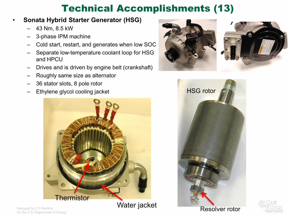
Technical Accomplishments (13) • Sonata Hybrid Starter Generator (HSG)
– 43 Nm, 8.5 kW – 3-phase IPM machine – Cold start, restart, and generates when low SOC – Separate low-temperature coolant loop for HSG
and HPCU – Drives and is driven by engine belt (crankshaft) – Roughly same size as alternator – 36 stator slots, 8 pole rotor – Ethylene glycol cooling jacket
Water jacket Thermistor
HSG rotor
Resolver rotor
Managed by UT-Battelle for the U.S. Department of Energy
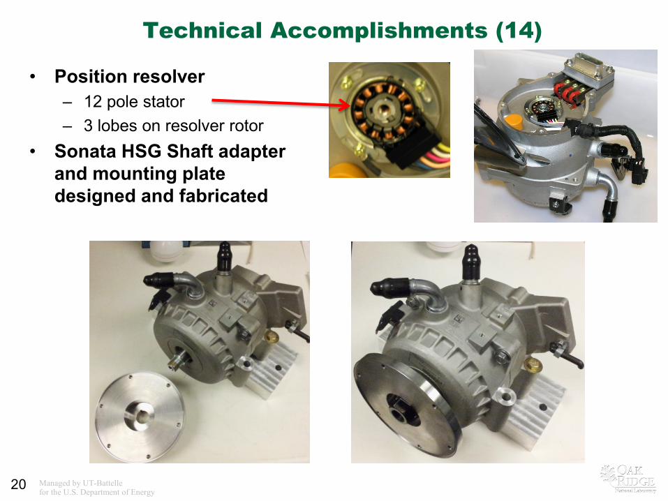
Technical Accomplishments (14)
• Position resolver – 12 pole stator – 3 lobes on resolver rotor
• Sonata HSG Shaft adapter and mounting plate designed and fabricated
20
Managed by UT-Battelle for the U.S. Department of Energy
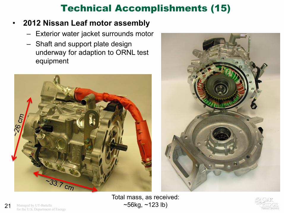
Technical Accomplishments (15)
21
• 2012 Nissan Leaf motor assembly – Exterior water jacket surrounds motor – Shaft and support plate design
underway for adaption to ORNL test equipment
Total mass, as received: ~56kg, ~123 lb)
Managed by UT-Battelle for the U.S. Department of Energy
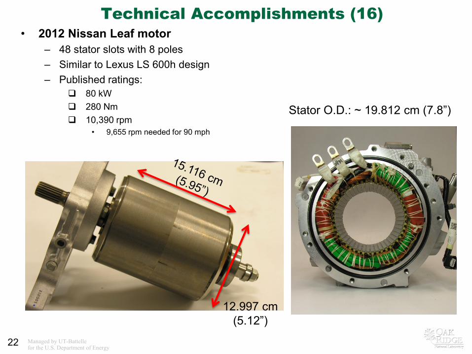
Technical Accomplishments (16)
22
• 2012 Nissan Leaf motor – 48 stator slots with 8 poles – Similar to Lexus LS 600h design – Published ratings:
80 kW 280 Nm 10,390 rpm
• 9,655 rpm needed for 90 mph
12.997 cm (5.12”)
Stator O.D.: ~ 19.812 cm (7.8”)
Managed by UT-Battelle for the U.S. Department of Energy
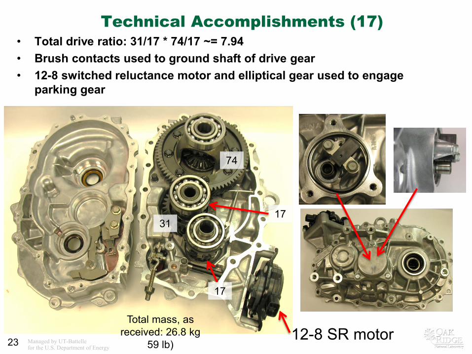
Technical Accomplishments (17) • Total drive ratio: 31/17 * 74/17 ~= 7.94 • Brush contacts used to ground shaft of drive gear • 12-8 switched reluctance motor and elliptical gear used to engage
parking gear
23 12-8 SR motor
17
31 17
74
Total mass, as received: 26.8 kg
59 lb)
Managed by UT-Battelle for the U.S. Department of Energy
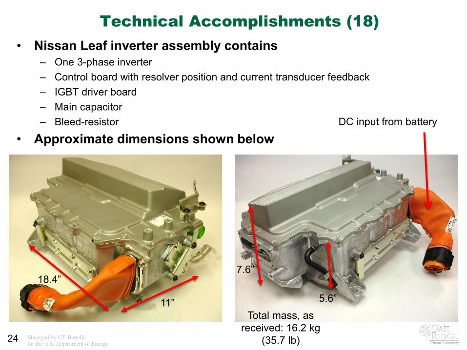
Technical Accomplishments (18)
24
DC input from battery
• Nissan Leaf inverter assembly contains – One 3-phase inverter – Control board with resolver position and current transducer feedback – IGBT driver board – Main capacitor – Bleed-resistor
• Approximate dimensions shown below
5.6” 11”
18.4” 7.6”
Total mass, as received: 16.2 kg
(35.7 lb)
Managed by UT-Battelle for the U.S. Department of Energy
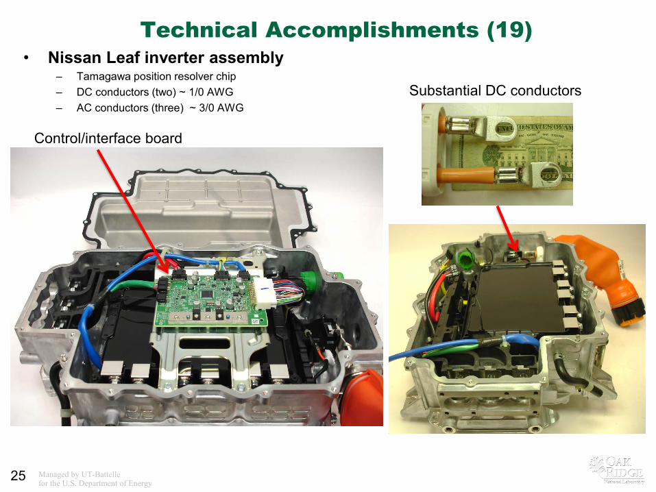
Technical Accomplishments (19) • Nissan Leaf inverter assembly
– Tamagawa position resolver chip – DC conductors (two) ~ 1/0 AWG – AC conductors (three) ~ 3/0 AWG
25
Control/interface board
Substantial DC conductors
Managed by UT-Battelle for the U.S. Department of Energy
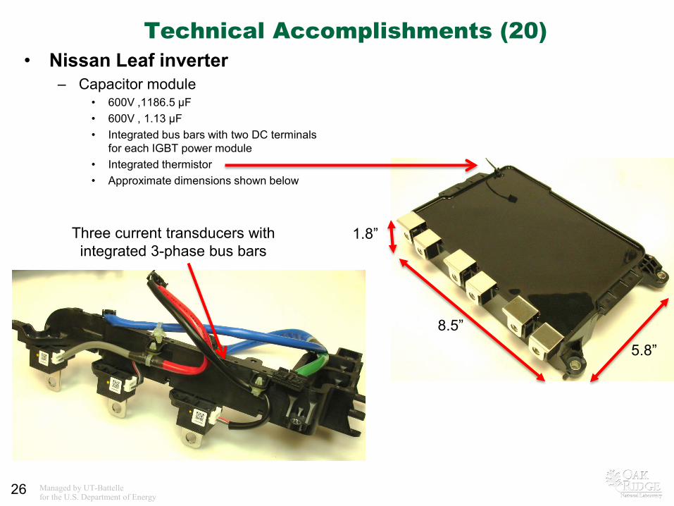
Technical Accomplishments (20) • Nissan Leaf inverter
– Capacitor module • 600V ,1186.5 µF • 600V , 1.13 µF • Integrated bus bars with two DC terminals
for each IGBT power module • Integrated thermistor • Approximate dimensions shown below
26
Three current transducers with integrated 3-phase bus bars
8.5” 5.8”
1.8”
Managed by UT-Battelle for the U.S. Department of Energy
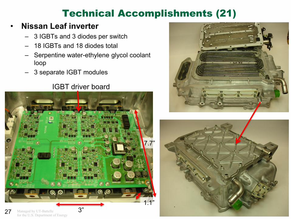
Technical Accomplishments (21) • Nissan Leaf inverter
– 3 IGBTs and 3 diodes per switch – 18 IGBTs and 18 diodes total – Serpentine water-ethylene glycol coolant
loop – 3 separate IGBT modules
27
12-8 SR motor
IGBT driver board
3”
7.7”
1.1”
Managed by UT-Battelle for the U.S. Department of Energy
28
Collaborations • Argonne National Laboratory
– ANL provides vehicle level data obtained during extensive drive cycle testing which enables the observation of common operation conditions and trends observed on a system-wide basis
– Converter, inverter, and motor characteristics such as efficiency and performance are supplied to ANL for use in system-wide vehicle modeling
• Electric Transportation Applications and Idaho National Laboratory – ETA and INL collaborate on a fleet vehicle testing program in which fleet vehicles
undergo normal driving and maintenance schedules. The study of components from these vehicles provides information related to the reliability and operation long-term susceptibility of the designs.
• National Renewable Energy Laboratory – NREL utilizes temperature measurements observed during performance and
efficiency tests to assess the characteristics of the thermal management system – NREL provides feedback and suggestions in regards to the measurements (such as
thermocouple placement) useful to thermal management system assessments • Oak Ridge National Laboratory, Materials Science & Technology Division
– Provides detailed material analysis of components such as magnets and power electronics packages
Managed by UT-Battelle for the U.S. Department of Energy
29
Future Work
• Benchmarking efforts will focus on technologies of interest to DOE, the Electrical and Electronics Technical Team, and Vehicle Systems Analysis Technical Team
Managed by UT-Battelle for the U.S. Department of Energy
30
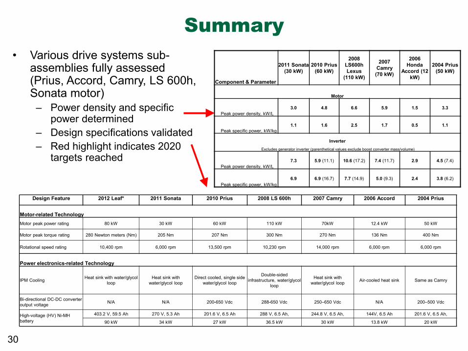
Summary • Various drive systems sub-
assemblies fully assessed (Prius, Accord, Camry, LS 600h, Sonata motor)
– Power density and specific power determined
– Design specifications validated – Red highlight indicates 2020
targets reached
Design Feature 2012 Leaf* 2011 Sonata 2010 Prius 2008 LS 600h 2007 Camry 2006 Accord 2004 Prius
Motor-related Technology Motor peak power rating 80 kW 30 kW 60 kW 110 kW 70kW 12.4 kW 50 kW
Motor peak torque rating 280 Newton meters (Nm) 205 Nm 207 Nm 300 Nm 270 Nm 136 Nm 400 Nm
Rotational speed rating 10,400 rpm 6,000 rpm 13,500 rpm 10,230 rpm 14,000 rpm 6,000 rpm 6,000 rpm
Power electronics-related Technology
IPM Cooling Heat sink with water/glycol loop
Heat sink with water/glycol loop
Direct cooled, single side water/glycol loop
Double-sided infrastructure, water/glycol
loop
Heat sink with water/glycol loop Air-cooled heat sink Same as Camry
Bi-directional DC-DC converter output voltage N/A N/A 200-650 Vdc 288-650 Vdc 250–650 Vdc N/A 200–500 Vdc
High-voltage (HV) Ni-MH battery
403.2 V, 59.5 Ah 270 V, 5.3 Ah 201.6 V, 6.5 Ah 288 V, 6.5 Ah, 244.8 V, 6.5 Ah, 144V, 6.5 Ah 201.6 V, 6.5 Ah,
90 kW 34 kW 27 kW 36.5 kW 30 kW 13.8 kW 20 kW
Component & Parameter
2011 Sonata (30 kW)
2010 Prius (60 kW)
2008 LS600h Lexus
(110 kW)
2007 Camry (70 kW)
2006 Honda
Accord (12 kW)
2004 Prius (50 kW)
Motor
Peak power density, kW/L 3.0 4.8 6.6 5.9 1.5 3.3
Peak specific power, kW/kg 1.1 1.6 2.5 1.7 0.5 1.1
Inverter
Excludes generator inverter (parenthetical values exclude boost converter mass/volume)
Peak power density, kW/L 7.3 5.9 (11.1) 10.6 (17.2) 7.4 (11.7) 2.9 4.5 (7.4)
Peak specific power, kW/kg 6.9 6.9 (16.7) 7.7 (14.9) 5.0 (9.3) 2.4 3.8 (6.2)