Embed Size (px)
Citation preview

1© KEMET Electronics Corporation • KEMET Tower • One East Broward Boulevard A4019_PEH506 • 4/24/2020Fort Lauderdale, FL 33301 USA • 954-766-2800 • www.kemet.com
One world. One KEMET
Benefits
• Snap-In• Long life, 3,000 hours at +85°C (VR, IR applied)• PCB mounting• Low ESR and ESL• High ripple current
Overview
KEMET's PEH506 is a long-life electrolytic capacitor designed to offer high ripple current capability and low mounting cost. Low ESR is the result of a very low resistive paper/electrolyte system. Low ESR, together with the TDC thermal concept, gives the PEH506 a high ripple current capability.
Applications
Typical applications for KEMET's PEH506 capacitor include switch mode power supplies (SMPS), drives, welding equipment, uninterruptible power supplies (UPS), and other power electronic applications where high current ratings and compact size are important.
Snap-In Aluminum Electrolytic Capacitors
PEH506, +85°C
Part Number System
PEH506 J AC 433 0 M 2
Series Rated Voltage (VDC) Size CodeCapacitance Code
(µF)Version
Capacitance Tolerance
Termination
Snap-In type Aluminum
Electrolytic
J = 35M = 63P = 100R = 200S = 250U = 350V = 400Y = 450
See Dimension Table
The last two digits represent
significant figures. The first digit
indicates the total number digits.
0 = Standard M = ±20% See Termination Table

2© KEMET Electronics Corporation • KEMET Tower • One East Broward Boulevard A4019_PEH506 • 4/24/2020Fort Lauderdale, FL 33301 USA • 954-766-2800 • www.kemet.com
Snap-In Aluminum Electrolytic Capacitors – PEH506, +85°C
Performance Characteristics
Item Performance CharacteristicsCapacitance Range 68 – 27,000 µF
Rated Voltage 35 – 450 VDC
Operating Temperature −40 to +85°C
Capacitance Tolerance ±20% at 100 Hz/+20°C
Operational LifetimeD (mm) Rated Voltage and Ripple
Current at +85°C (hours) Rated Voltage at +85°C (hours)
22–35 3,000 6,000
Shelf Life 4 years at +40°C 0 VDC
Leakage CurrentI = 0.003 CV (µA)
C = rated capacitance (µF), V = rated voltage (VDC). Voltage applied for 5 minutes at +20°C.
Vibration Test Specifications
Procedure Requirements
0.75 mm displacement amplitude or 10 g maximum acceleration.
Vibration applied for three 2-hour sessions at 10 – 500 Hz (Capacitor
clamped by body).
No leakage of electrolyte or other visible damage. Deviations in capacitance from initial measurements must not exceed: Δ C/C < 5%
Standards IEC 60384-4 long life grade 40/85/56, in accordance with CECC 30 301–809
Test Method & Performance
Endurance Life TestConditions Performance
Temperature +85°C
Test Duration 2,000 hours
Ripple Current Maximum ripple current specified in table
Voltage The sum of DC voltage and the peak AC voltage must not exceed the rated voltage of the capacitor
Performance The following specifications will be satisfied when the capacitor is tested at +20°C:
Capacitance Change≤ 160 V Within 15% of the initial value
> 160 V Within 10% of the initial value
Equivalent Series Resistance Does not exceed 200% of the initial value
Leakage Current Does not exceed leakage current limit
3© KEMET Electronics Corporation • KEMET Tower • One East Broward Boulevard A4019_PEH506 • 4/24/2020Fort Lauderdale, FL 33301 USA • 954-766-2800 • www.kemet.com
Snap-In Aluminum Electrolytic Capacitors – PEH506, +85°C
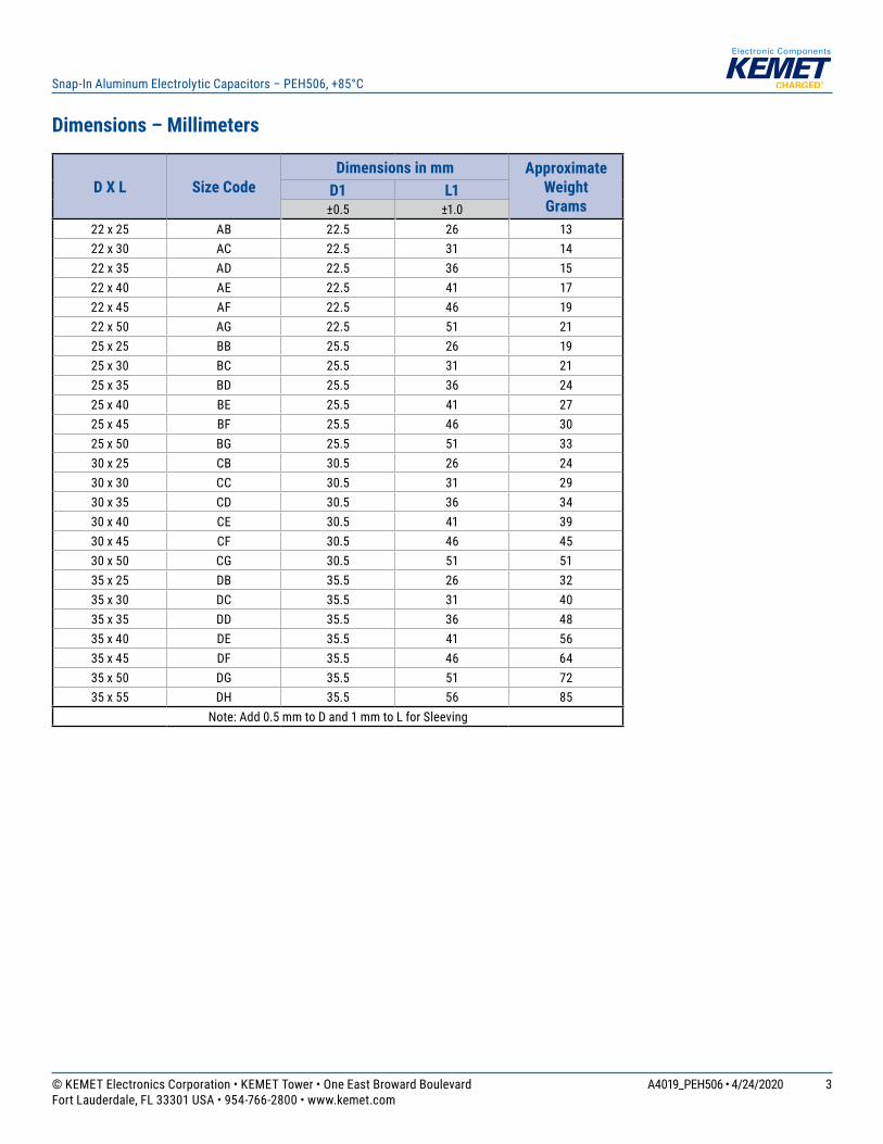
Dimensions – Millimeters
D X L Size CodeDimensions in mm Approximate
Weight Grams
D1 L1±0.5 ±1.0
22 x 25 AB 22.5 26 1322 x 30 AC 22.5 31 1422 x 35 AD 22.5 36 1522 x 40 AE 22.5 41 1722 x 45 AF 22.5 46 1922 x 50 AG 22.5 51 2125 x 25 BB 25.5 26 1925 x 30 BC 25.5 31 2125 x 35 BD 25.5 36 2425 x 40 BE 25.5 41 2725 x 45 BF 25.5 46 3025 x 50 BG 25.5 51 3330 x 25 CB 30.5 26 2430 x 30 CC 30.5 31 2930 x 35 CD 30.5 36 3430 x 40 CE 30.5 41 3930 x 45 CF 30.5 46 4530 x 50 CG 30.5 51 5135 x 25 DB 35.5 26 3235 x 30 DC 35.5 31 4035 x 35 DD 35.5 36 4835 x 40 DE 35.5 41 5635 x 45 DF 35.5 46 6435 x 50 DG 35.5 51 7235 x 55 DH 35.5 56 85
Note: Add 0.5 mm to D and 1 mm to L for Sleeving

4© KEMET Electronics Corporation • KEMET Tower • One East Broward Boulevard A4019_PEH506 • 4/24/2020Fort Lauderdale, FL 33301 USA • 954-766-2800 • www.kemet.com
Snap-In Aluminum Electrolytic Capacitors – PEH506, +85°C
Termination Tables
Termination Code2 2S 3 4 4S
Diameter (mm)
22 • • •25 • • •30 • • •35 • • • • •
Mounting: These capacitors are designed to be mounted by their terminations alone and may be used in any position. Dummy pins on 4-pin decks must be isolated.
Termination Code
Termination Style
LL±1
Standard Termination Option
2 2 Pin 6.3
Other Termination Options
2S 2 Pin 4
3 3 Pin 4
4 4 Pin 6.3
4S 4 Pin 4
Dimensions in mm

5© KEMET Electronics Corporation • KEMET Tower • One East Broward Boulevard A4019_PEH506 • 4/24/2020Fort Lauderdale, FL 33301 USA • 954-766-2800 • www.kemet.com
Snap-In Aluminum Electrolytic Capacitors – PEH506, +85°C
Termination Tables cont.
L
SIDE VIEW TERMINALEND VIEW
D
PCB LAYOUT
2 ±0.1
Style 2/2S
L
SIDE VIEW TERMINALEND VIEW
D
PCB LAYOUT
4.75 ±0.1
Style 3
L
SIDE VIEW TERMINALEND VIEW
D
PCB LAYOUTStyle 4/4S
LL10 ±0.1
10 ±0.1
+ -
3.3 ±0.1
Ø2.5 Minimum+ ve
Ø2 ±0.1 Typical
+
-
30°30°
- ve4 Holes Ø2 ±0.1on a Ø22.5 PCD
+ ve
L
SIDE VIEW TERMINALEND VIEW
D
PCB LAYOUTStyle G/H
+
-
30°30°
- ve5 Holes Ø2 ±0.1on a Ø25.0 PCD
+ ve
LL
LL
LL
30°

6© KEMET Electronics Corporation • KEMET Tower • One East Broward Boulevard A4019_PEH506 • 4/24/2020Fort Lauderdale, FL 33301 USA • 954-766-2800 • www.kemet.com
Snap-In Aluminum Electrolytic Capacitors – PEH506, +85°C
Shelf Life
The capacitance, ESR and impedance of a capacitor will not change significantly after extended storage periods, however the leakage current will very slowly increase. KEMET products are particularly stable and allow a shelf life in excess of three years at 40°C. See sectional specification under each product series for specific data.
Re-age (Reforming) Procedure
Apply the rated voltage to the capacitor at room temperature for a period of one hour, or until the leakage current has fallen to a steady value below the specified limit. During re-aging a maximum charging current of twice the specified leakage current or 5 mA (whichever is greater) is suggested.
Reliability
The reliability of a component can be defined as the probability that it will perform satisfactorily under a given set of conditions for a given length of time. In practice, it is impossible to predict with absolute certainty how any individual component will perform; thus, we must utilize probability theory. It is also necessary to clearly define the level of stress involved (e.g. operating voltage, ripple current, temperature and time). Finally, the meaning of satisfactory performance must be defined by specifying a set of conditions which determine the end of life of the component. Reliability as a function of time, R(t), is normally expressed as: R(t)=e-λt where R(t) is the probability that the component will perform satisfactorily for time t, and λ is the failure rate.
Failure Rate
The failure rate is the number of components failing per unit time. The failure rate of most electronic components follows the characteristic pattern:
• Early failures are removed during the manufacturing process. • The operational life is characterized by a constant failure rate.• The wear out period is characterized by a rapidly increasing failure rate. The failures in time (FIT) are given with a 60% confidence level for the various type codes. By convention, FIT is expressed as 1 x 10⁻⁹ failures per hour. Failure rate is also expressed as a percentage of failures per 1,000 hours.e.g., 100 FIT = 1 x 10⁻⁷ failures per hour = 0.01%/1,000 hours
End of Life Definition Catastrophic Failure: short circuit, open circuit or safety vent operationParametric Failure:• Change in capacitance > ±10%• Leakage current > specified limit• ESR > 2 x initial ESR value

7© KEMET Electronics Corporation • KEMET Tower • One East Broward Boulevard A4019_PEH506 • 4/24/2020Fort Lauderdale, FL 33301 USA • 954-766-2800 • www.kemet.com
Snap-In Aluminum Electrolytic Capacitors – PEH506, +85°C
MTBFThe mean time between failures (MTBF) is simply the inverse of the failure rate. MTBF= 1/λ
wear outearly failures
operational life
Failu
re R
ate
Time
The failure rate is derived from our periodic test results. The failure rate (λR) is, therefore, only given at test temperature for life tests. An estimation is also given at 40°C. The expected failure rate for this capacitor range is based on our periodic test results for capacitors with structural similarity. Failure rate is frequently quoted in FIT (Failures In Time) where 1 FIT = 1 x 10⁻⁹ failures per hour. Failure rate per hour includes both catastrophic and parametric failures.
Environmental Compliance
All Part Numbers in this datasheet are Reach and RoHS compliant.
As an environmentally conscious company, KEMET is working continuously with improvements concerning the environmental effects of both our capacitors and their production.
In Europe (RoHS Directive) and in some other geographical areas such as China, legislation has been put in place to prevent the use of some hazardous materials, such as lead (Pb), in electronic equipment. All products in this catalog are produced to help our customers' obligations to guarantee their products and fulfill these legislative requirements. The only material of concern in our products has been lead (Pb), which has been removed from all designs to fulfill the requirement of containing less than 0.1% of lead in any homogeneous material. KEMET will closely follow any changes in legislation worldwide and make any necessary changes in its products, whenever needed.
Some customer segments such as medical, military and automotive electronics may still require the use of lead in electrode coatings. To clarify the situation and distinguish products from each other, a special symbol is used on the packaging labels for RoHS compatible capacitors.
Due to customer requirements, there may appear additional markings such as lead-free (LF), or lead-free wires (LFW) on the label.

8© KEMET Electronics Corporation • KEMET Tower • One East Broward Boulevard A4019_PEH506 • 4/24/2020Fort Lauderdale, FL 33301 USA • 954-766-2800 • www.kemet.com
Snap-In Aluminum Electrolytic Capacitors – PEH506, +85°C
Table 1 – Ratings & Part Number Reference
(1) Termination code: See Termination Tables for available options.
VDCRated
Capacitance Size CodeCase Size Ripple Current
Maximum ESR MaximumPart Number
100 Hz 20°C (µF) D x L (mm) 100 Hz
85°C (A) 20 kHz
40°C (A)100 Hz
20°C (mΩ)100 kHz
20°C (mΩ)35 3300 AC 22 x 30 2.9 6.4 110 92 PEH506JAC4330M(1)35 3900 AC 22 x 30 3.1 6.6 96 82 PEH506JAC4390M(1)35 4700 AD 22 x 35 3.5 7.7 79 67 PEH506JAD4470M(1)35 4700 BC 25 x 30 3.3 7.0 85 72 PEH506JBC4470M(1)35 5600 AE 22 x 40 4.0 8.6 67 56 PEH506JAE4560M(1)35 5600 BC 25 x 30 3.4 7.0 76 66 PEH506JBC4560M(1)35 6800 AE 22 x 40 4.2 8.9 58 50 PEH506JAE4680M(1)35 6800 BD 25 x 35 4.0 8.2 62 53 PEH506JBD4680M(1)35 6800 CC 30 x 30 3.6 7.2 70 62 PEH506JCC4680M(1)35 8200 AG 22 x 50 5.0 10.6 47 40 PEH506JAG4820M(1)35 8200 BE 25 x 40 4.5 9.4 52 45 PEH506JBE4820M(1)35 8200 CC 30 x 30 3.6 6.9 66 59 PEH506JCC4820M(1)35 10000 BF 25 x 45 5.0 10.4 43 38 PEH506JBF5100M(1)35 10000 CD 30 x 35 4.2 8.3 53 47 PEH506JCD5100M(1)35 10000 DC 35 x 30 3.7 7.0 66 61 PEH506JDC5100M(1)35 12000 BG 25 x 50 5.5 11.3 37 32 PEH506JBG5120M(1)35 12000 CE 30 x 40 4.8 9.4 44 39 PEH506JCE5120M(1)35 12000 DC 35 x 30 3.5 6.5 69 65 PEH506JDC5120M(1)35 15000 CF 30 x 45 5.3 10.4 37 33 PEH506JCF5150M(1)35 15000 DD 35 x 35 4.1 7.8 55 51 PEH506JDD5150M(1)35 18000 DE 35 x 40 4.7 8.9 45 42 PEH506JDE5180M(1)35 22000 DF 35 x 45 5.2 9.8 39 37 PEH506JDF5220M(1)35 27000 DG 35 x 50 5.7 10.6 35 33 PEH506JDG5270M(1)63 1200 AB 22 x 25 2.1 5.3 160 110 PEH506MAB4120M(1)63 1500 AC 22 x 30 2.5 6.4 120 89 PEH506MAC4150M(1)63 1800 AC 22 x 30 2.6 6.6 110 78 PEH506MAC4180M(1)63 2200 AD 22 x 35 3.1 7.7 87 63 PEH506MAD4220M(1)63 2200 BC 25 x 30 2.9 7.0 93 69 PEH506MBC4220M(1)63 2700 AE 22 x 40 3.5 8.8 72 52 PEH506MAE4270M(1)63 2700 BD 25 x 35 3.4 8.3 75 56 PEH506MBD4270M(1)63 3300 AG 22 x 50 4.1 10.4 58 42 PEH506MAG4330M(1)63 3300 BE 25 x 40 3.9 9.4 62 46 PEH506MBE4330M(1)63 3300 CC 30 x 30 3.3 7.0 76 60 PEH506MCC4330M(1)63 3900 BF 25 x 45 4.4 10.4 53 40 PEH506MBF4390M(1)63 3900 CD 30 x 35 3.8 8.4 62 48 PEH506MCD4390M(1)63 4700 BG 25 x 50 4.8 11.3 45 34 PEH506MBG4470M(1)63 4700 CE 30 x 40 4.4 9.6 51 40 PEH506MCE4470M(1)63 4700 DC 35 x 30 3.4 6.7 74 63 PEH506MDC4470M(1)63 5600 CE 30 x 40 4.4 9.2 48 39 PEH506MCE4560M(1)63 5600 DD 35 x 35 4.0 8.1 58 49 PEH506MDD4560M(1)63 6800 CF 30 x 45 4.9 10.2 41 33 PEH506MCF4680M(1)63 6800 DE 35 x 40 4.6 9.3 48 40 PEH506MDE4680M(1)63 8200 DF 35 x 45 5.1 10.3 41 35 PEH506MDF4820M(1)63 10000 DG 35 x 50 5.5 11.0 37 31 PEH506MDG5100M(1)
100 560 AB 22 x 25 1.5 3.6 370 290 PEH506PAB3560M(1)100 680 AC 22 x 30 1.7 4.3 300 230 PEH506PAC3680M(1)100 680 BB 25 x 25 1.7 4.1 310 240 PEH506PBB3680M(1)100 820 AD 22 x 35 2.0 5.0 250 190 PEH506PAD3820M(1)100 820 BC 25 x 30 2.0 4.8 260 200 PEH506PBC3820M(1)100 1000 AE 22 x 40 2.3 5.7 210 160 PEH506PAE4100M(1)100 1000 BC 25 x 30 2.1 5.1 210 170 PEH506PBC4100M(1)100 1200 AE 22 x 40 2.5 6.1 170 140 PEH506PAE4120M(1)100 1200 BD 25 x 35 2.5 6.0 180 140 PEH506PBD4120M(1)100 1500 AF 22 x 45 2.8 6.9 140 110 PEH506PAF4150M(1)100 1500 BE 25 x 40 2.9 6.8 140 110 PEH506PBE4150M(1)100 1800 BF 25 x 45 3.2 7.6 120 95 PEH506PBF4180M(1)100 1800 CD 30 x 35 3.1 7.0 130 100 PEH506PCD4180M(1)100 2200 BG 25 x 50 3.6 8.5 100 78 PEH506PBG4220M(1)100 2200 CE 30 x 40 3.5 8.0 110 84 PEH506PCE4220M(1)100 2200 DC 35 x 30 2.9 6.2 120 100 PEH506PDC4220M(1)
VDC Rated Capacitance Size Code Case Size Ripple Current ESR Part Number

9© KEMET Electronics Corporation • KEMET Tower • One East Broward Boulevard A4019_PEH506 • 4/24/2020Fort Lauderdale, FL 33301 USA • 954-766-2800 • www.kemet.com
Snap-In Aluminum Electrolytic Capacitors – PEH506, +85°C
Table 1 – Ratings & Part Number Reference cont.
(1) Termination code: See Termination Tables for available options.
VDCRated
Capacitance Size CodeCase Size Ripple Current
Maximum ESR MaximumPart Number
100 Hz 20°C (µF) D x L (mm) 100 Hz
85°C (A) 20 kHz
40°C (A)100 Hz
20°C (mΩ)100 kHz
20°C (mΩ)100 2700 CF 30 x 45 4.0 8.9 88 70 PEH506PCF4270M(1)100 2700 DD 35 x 35 3.5 7.3 100 82 PEH506PDD4270M(1)100 3300 CG 30 x 50 4.4 9.8 73 59 PEH506PCG4330M(1)100 3300 DE 35 x 40 3.9 8.4 82 68 PEH506PDE4330M(1)100 3900 DF 35 x 45 4.4 9.3 70 58 PEH506PDF4390M(1)100 4700 DG 35 x 50 4.9 10.1 60 50 PEH506PDG4470M(1)200 270 AC 22 x 30 1.2 5.4 510 270 PEH506RAC3270M(1)200 270 BB 25 x 25 1.2 4.8 520 290 PEH506RBB3270M(1)200 330 AD 22 x 35 1.4 6.2 420 220 PEH506RAD3330M(1)200 330 BC 25 x 30 1.4 5.9 420 230 PEH506RBC3330M(1)200 390 AD 22 x 35 1.5 6.5 360 190 PEH506RAD3390M(1)200 390 BC 25 x 30 1.5 6.0 360 200 PEH506RBC3390M(1)200 470 AE 22 x 40 1.7 7.4 300 160 PEH506RAE3470M(1)200 470 BD 25 x 35 1.7 7.0 300 160 PEH506RBD3470M(1)200 470 CC 30 x 30 1.7 6.4 310 170 PEH506RCC3470M(1)200 560 AF 22 x 45 1.9 8.2 250 140 PEH506RAF3560M(1)200 560 BE 25 x 40 1,9 8.0 250 140 PEH506RBE3560M(1)200 680 AG 22 x 50 2.1 9.1 210 110 PEH506RAG3680M(1)200 680 BF 25 x 45 2.2 8.9 210 110 PEH506RBF3680M(1)200 680 CD 30 x 35 2.1 7.4 220 130 PEH506RCD3680M(1)200 820 BG 25 x 50 2.5 9.7 170 96 PEH506RBG3820M(1)200 820 CD 30 x 35 2.3 7.1 190 110 PEH506RCD3820M(1)200 1000 CE 30 x 40 2.6 8.1 160 92 PEH506RCE4100M(1)200 1000 DD 35 x 35 2.5 7.2 170 100 PEH506RDD4100M(1)200 1200 CF 30 x 45 2.9 9.0 130 78 PEH506RCF4120M(1)200 1200 DE 35 x 40 2.9 8.2 140 85 PEH506RDE4120M(1)200 1500 DF 35 x 45 3.3 9.0 110 71 PEH506RDF4150M(1)200 1800 DG 35 x 50 3.6 9.8 97 61 PEH506RDG4180M(1)200 2200 DH 35 x 55 4.0 10.4 82 53 PEH506RDH4220M(1)250 220 AC 22 x 30 1.1 5.5 520 260 PEH506SAC3220M(1)250 220 BB 25 x 25 1.1 4.8 530 270 PEH506SBB3220M(1)250 270 AD 22 x 35 1.3 6.4 420 210 PEH506SAD3270M(1)250 270 BC 25 x 30 1.3 5.9 430 210 PEH506SBC3270M(1)250 330 AE 22 x 40 1.5 7.2 350 170 PEH506SAE3330M(1)250 330 BC 25 x 30 1.4 6.0 360 180 PEH506SBC3330M(1)250 330 CB 30 x 25 1.4 4.9 380 200 PEH506SCB3330M(1)250 390 AF 22 x 45 1.7 8.1 290 140 PEH506SAF3390M(1)250 390 BD 25 x 35 1.6 7.1 300 150 PEH506SBD3390M(1)250 470 AG 22 x 50 1.9 8.9 250 120 PEH506SAG3470M(1)250 470 BE 25 x 40 1.9 8.0 250 130 PEH506SBE3470M(1)250 470 CC 30 x 30 1.8 6.1 270 140 PEH506SCC3470M(1)250 560 AG 22 x 50 2.1 9.2 210 110 PEH506SAG3560M(1)250 560 BF 25 x 45 2.1 8.9 210 110 PEH506SBF3560M(1)250 680 BG 25 x 50 2.4 9.8 180 90 PEH506SBG3680M(1)250 680 CE 30 x 40 2.3 8.3 180 98 PEH506SCE3680M(1)250 680 DC 35 x 30 2.1 5.8 210 120 PEH506SDC3680M(1)250 820 CF 30 x 45 2.6 9.2 150 83 PEH506SCF3820M(1)250 820 DD 35 x 35 2.4 7.0 170 99 PEH506SDD3820M(1)250 1000 CG 30 x 50 3.0 10.0 130 70 PEH506SCG4100M(1)250 1000 DE 35 x 40 2.8 8.0 140 82 PEH506SDE4100M(1)250 1200 DF 35 x 45 3.1 8.9 120 70 PEH506SDF4120M(1)250 1500 DG 35 x 50 3.5 9.5 98 59 PEH506SDG4150M(1)350 82 AB 22 x 25 0.7 3.0 1600 970 PEH506UAB2820M(1)350 100 AC 22 x 30 0.8 3.5 1300 800 PEH506UAC3100M(1)350 150 AD 22 x 35 1.1 4.4 860 540 PEH506UAD3150M(1)350 150 BC 25 x 30 1.1 4.3 870 550 PEH506UBC3150M(1)350 180 AE 22 x 40 1.2 4.9 720 450 PEH506UAE3180M(1)350 220 AF 22 x 45 1.4 5.6 590 370 PEH506UAF3220M(1)350 220 BD 25 x 35 1.3 5.3 600 380 PEH506UBD3220M(1)350 220 CC 30 x 30 1.4 5.1 610 390 PEH506UCC3220M(1)
VDC Rated Capacitance Size Code Case Size Ripple Current ESR Part Number

10© KEMET Electronics Corporation • KEMET Tower • One East Broward Boulevard A4019_PEH506 • 4/24/2020Fort Lauderdale, FL 33301 USA • 954-766-2800 • www.kemet.com
Snap-In Aluminum Electrolytic Capacitors – PEH506, +85°C
Table 1 – Ratings & Part Number Reference cont.
(1) Termination code: See Termination Tables for available options.
VDCRated
Capacitance Size CodeCase Size Ripple Current
Maximum ESR MaximumPart Number
100 Hz 20°C (µF) D x L (mm) 100 Hz
85°C (A) 20 kHz
40°C (A)100 Hz
20°C (mΩ)100 kHz
20°C (mΩ)350 270 AG 22 x 50 1.5 6.3 480 310 PEH506UAG3270M(1)350 270 BE 25 x 40 1.5 6.0 490 310 PEH506UBE3270M(1)350 330 BG 25 x 50 1.8 7.1 400 250 PEH506UBG3330M(1)350 330 CE 30 x 40 1.8 6.8 400 260 PEH506UCE3330M(1)350 330 DC 35 x 30 1.7 5.6 420 280 PEH506UDC3330M(1)350 390 BG 25 x 50 2.0 7.5 340 220 PEH506UBG3390M(1)350 390 CE 30 x 40 2.0 7.0 350 220 PEH506UCE3390M(1)350 470 CF 30 x 45 2.2 7.9 290 190 PEH506UCF3470M(1)350 470 DD 35 x 35 2.1 6.6 300 200 PEH506UDD3470M(1)350 560 CG 30 x 50 2.5 8.7 240 160 PEH506UCG3560M(1)350 560 DE 35 x 40 2.4 7.5 250 170 PEH506UDE3560M(1)350 680 DF 35 x 45 2.7 8.4 210 140 PEH506UDF3680M(1)400 82 AC 22 x 30 0.8 3.4 1300 810 PEH506VAC2820M(1)400 100 AC 22 x 30 0.9 3.7 1100 670 PEH506VAC3100M(1)400 100 BB 25 x 25 0.9 3.6 1100 680 PEH506VBB3100M(1)400 120 AD 22 x 35 1.0 4.3 920 560 PEH506VAD3120M(1)400 120 BC 25 x 30 1.0 4.2 930 570 PEH506VBC3120M(1)400 120 CB 30 x 25 1.0 4.0 940 580 PEH506VCB3120M(1)400 150 AE 22 x 40 1.2 4.9 740 450 PEH506VAE3150M(1)400 150 BD 25 x 35 1.2 4.9 740 450 PEH506VBD3150M(1)400 150 CB 30 x 25 1.1 4.2 770 480 PEH506VCB3150M(1)400 180 AF 22 x 45 1.3 5.5 620 380 PEH506VAF3180M(1)400 180 CC 30 x 30 1.3 5.1 630 390 PEH506VCC3180M(1)400 220 AG 22 x 50 1.5 6.2 510 310 PEH506VAG3220M(1)400 220 BE 25 x 40 1.5 6.0 510 320 PEH506VBE3220M(1)400 220 CD 30 x 35 1.5 5.9 520 320 PEH506VCD3220M(1)400 220 DB 35 x 25 1.4 4.5 550 350 PEH506VDB3220M(1)400 270 BF 25 x 45 1.7 6.7 420 260 PEH506VBF3270M(1)400 270 CD 30 x 35 1.7 6.2 430 270 PEH506VCD3270M(1)400 330 CE 30 x 40 1.9 7.0 350 220 PEH506VCE3330M(1)400 330 DD 35 x 35 1.9 6.7 360 230 PEH506VDD3330M(1)400 390 CG 30 x 50 2.2 8.4 290 180 PEH506VCG3390M(1)400 390 DE 35 x 40 2.2 7.6 300 190 PEH506VDE3390M(1)400 470 DF 35 x 45 2.5 8.5 250 160 PEH506VDF3470M(1)400 560 DG 35 x 50 2.8 9.3 210 140 PEH506VDG3560M(1)450 68 AC 22 x 30 0.8 3.5 1300 780 PEH506YAC2680M(1)450 68 BB 25 x 25 0.8 3.4 1300 790 PEH506YBB2680M(1)450 82 AC 22 x 30 0.9 3.7 1100 670 PEH506YAC2820M(1)450 82 BB 25 x 25 0.9 3.6 1100 680 PEH506YBB2820M(1)450 100 AD 22 x 35 1.0 4.4 910 540 PEH506YAD3100M(1)450 100 BC 25 x 30 1.0 4.3 920 540 PEH506YBC3100M(1)450 120 AE 22 x 40 1.1 5.0 760 450 PEH506YAE3120M(1)450 120 BC 25 x 30 1.1 4.5 780 470 PEH506YBC3120M(1)450 120 CB 30 x 25 1.1 4.2 800 480 PEH506YCB3120M(1)450 150 AF 22 x 45 1.3 5.6 620 370 PEH506YAF3150M(1)450 150 BD 25 x 35 1.3 5.3 620 370 PEH506YBD3150M(1)450 150 CC 30 x 30 1.3 5.1 630 380 PEH506YCC3150M(1)450 180 AG 22 x 50 1.4 6.2 520 310 PEH506YAG3180M(1)450 180 BE 25 x 40 1.4 6.0 520 310 PEH506YBE3180M(1)450 180 CC 30 x 30 1.4 5.3 540 330 PEH506YCC3180M(1)450 220 BF 25 x 45 1.6 6.8 430 260 PEH506YBF3220M(1)450 220 CD 30 x 35 1.6 6.2 440 270 PEH506YCD3220M(1)450 220 DC 35 x 30 1.6 5.6 450 280 PEH506YDC3220M(1)450 270 CE 30 x 40 1.9 7.1 360 220 PEH506YCE3270M(1)450 270 DD 35 x 35 1.9 6.7 360 230 PEH506YDD3270M(1)450 330 CG 30 x 50 2.2 8.5 290 170 PEH506YCG3330M(1)450 330 DE 35 x 40 2.2 7.6 300 180 PEH506YDE3330M(1)450 390 DE 35 x 40 2.3 7.4 260 160 PEH506YDE3390M(1)450 470 DG 35 x 50 2.7 9.3 210 130 PEH506YDG3470M(1)
VDC Rated Capacitance Size Code Case Size Ripple Current ESR Part Number
11© KEMET Electronics Corporation • KEMET Tower • One East Broward Boulevard A4019_PEH506 • 4/24/2020Fort Lauderdale, FL 33301 USA • 954-766-2800 • www.kemet.com
Snap-In Aluminum Electrolytic Capacitors – PEH506, +85°C
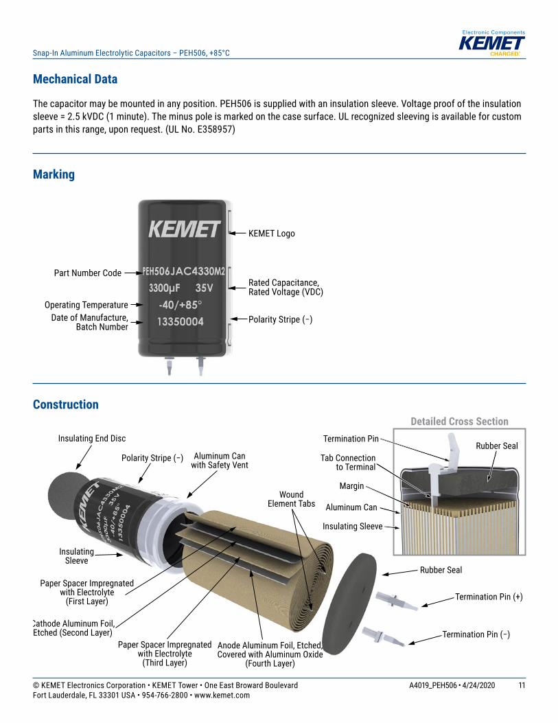
Mechanical Data
The capacitor may be mounted in any position. PEH506 is supplied with an insulation sleeve. Voltage proof of the insulation sleeve = 2.5 kVDC (1 minute). The minus pole is marked on the case surface. UL recognized sleeving is available for custom parts in this range, upon request. (UL No. E358957)
Marking
KEMET Logo
Rated Capacitance,Rated Voltage (VDC)
Part Number Code
Operating TemperatureDate of Manufacture,
Batch NumberPolarity Stripe (−)
ConstructionDetailed Cross Section
Margin
Termination Pin (+)
Rubber Seal
Rubber Seal
InsulatingSleeve
Aluminum Can with Safety Vent
WoundElement Tabs
Termination Pin
Tab Connectionto Terminal
Aluminum Can
Insulating Sleeve
Polarity Stripe (−)
Insulating End Disc
Termination Pin (−)
Paper Spacer Impregnatedwith Electrolyte
(First Layer)
Paper Spacer Impregnated with Electrolyte
(Third Layer)
Anode Aluminum Foil, Etched, Covered with Aluminum Oxide
(Fourth Layer)
Cathode Aluminum Foil, Etched (Second Layer)
12© KEMET Electronics Corporation • KEMET Tower • One East Broward Boulevard A4019_PEH506 • 4/24/2020Fort Lauderdale, FL 33301 USA • 954-766-2800 • www.kemet.com
Snap-In Aluminum Electrolytic Capacitors – PEH506, +85°C
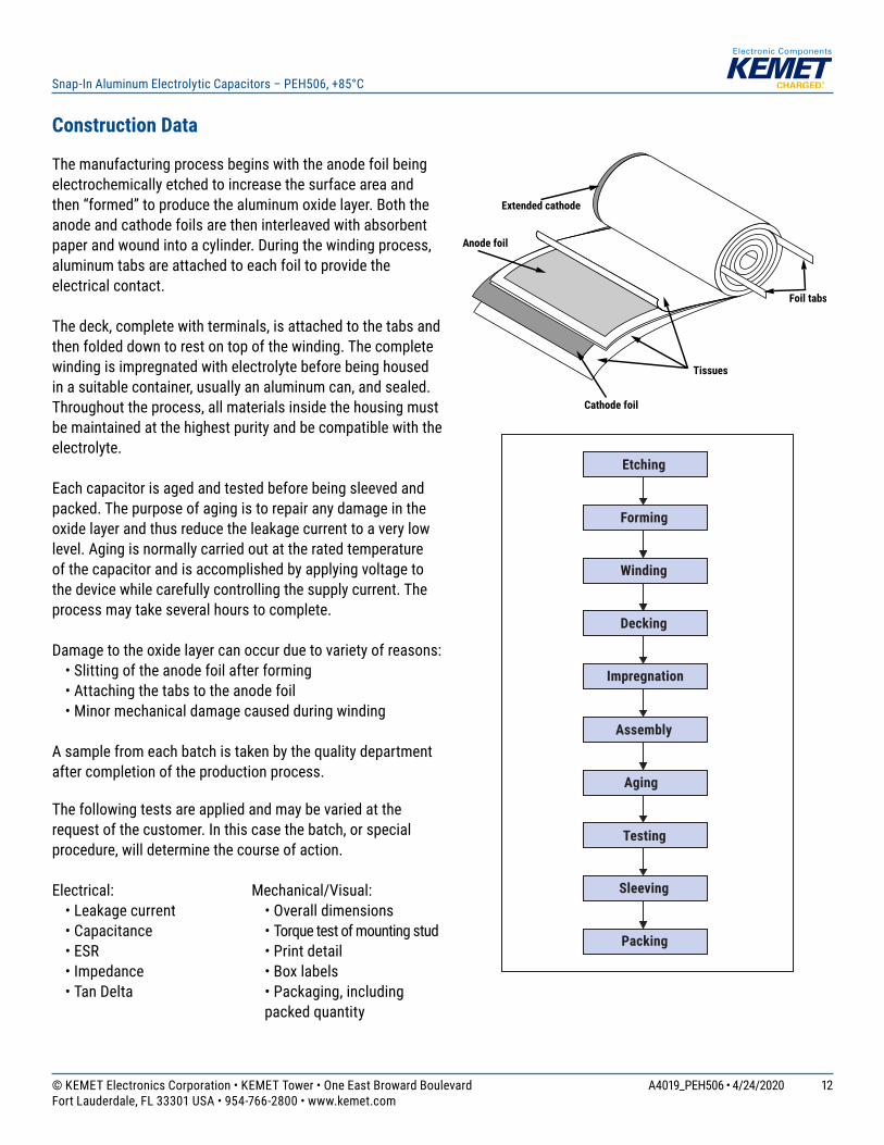
Construction Data
The manufacturing process begins with the anode foil being electrochemically etched to increase the surface area and then “formed” to produce the aluminum oxide layer. Both the anode and cathode foils are then interleaved with absorbent paper and wound into a cylinder. During the winding process, aluminum tabs are attached to each foil to provide the electrical contact. The deck, complete with terminals, is attached to the tabs and then folded down to rest on top of the winding. The complete winding is impregnated with electrolyte before being housed in a suitable container, usually an aluminum can, and sealed. Throughout the process, all materials inside the housing must be maintained at the highest purity and be compatible with the electrolyte. Each capacitor is aged and tested before being sleeved and packed. The purpose of aging is to repair any damage in the oxide layer and thus reduce the leakage current to a very low level. Aging is normally carried out at the rated temperature of the capacitor and is accomplished by applying voltage to the device while carefully controlling the supply current. The process may take several hours to complete.
Damage to the oxide layer can occur due to variety of reasons: • Slitting of the anode foil after forming • Attaching the tabs to the anode foil • Minor mechanical damage caused during winding
A sample from each batch is taken by the quality department after completion of the production process.
The following tests are applied and may be varied at the request of the customer. In this case the batch, or special procedure, will determine the course of action.
Electrical: • Leakage current • Capacitance • ESR • Impedance • Tan Delta
Mechanical/Visual: • Overall dimensions • Torque test of mounting stud • Print detail • Box labels • Packaging, including
packed quantity
Extended cathode
Anode foil
Cathode foil
Tissues
Foil tabs
Aging
Etching
Forming
Winding
Decking
Impregnation
Assembly
Testing
Sleeving
Packing

13© KEMET Electronics Corporation • KEMET Tower • One East Broward Boulevard A4019_PEH506 • 4/24/2020Fort Lauderdale, FL 33301 USA • 954-766-2800 • www.kemet.com
Snap-In Aluminum Electrolytic Capacitors – PEH506, +85°C
KEMET Electronics Corporation Sales Offi ces
For a complete list of our global sales offi ces, please visit www.kemet.com/sales.
DisclaimerAll product specifi cations, statements, information and data (collectively, the “Information”) in this datasheet are subject to change. The customer is responsible for checking and verifying the extent to which the Information contained in this publication is applicable to an order at the time the order is placed. All Information given herein is believed to be accurate and reliable, but it is presented without guarantee, warranty, or responsibility of any kind, expressed or implied.
Statements of suitability for certain applications are based on KEMET Electronics Corporation’s (“KEMET”) knowledge of typical operating conditions for such applications, but are not intended to constitute – and KEMET specifi cally disclaims – any warranty concerning suitability for a specifi c customer application or use. The Information is intended for use only by customers who have the requisite experience and capability to determine the correct products for their application. Any technical advice inferred from this Information or otherwise provided by KEMET with reference to the use of KEMET’s products is given gratis, and KEMET assumesno obligation or liability for the advice given or results obtained.
Although KEMET designs and manufactures its products to the most stringent quality and safety standards, given the current state of the art, isolated component failures may still occur. Accordingly, customer applications which require a high degree of reliability or safety should employ suitable designs or other safeguards (such as installation of protective circuitry or redundancies) in order to ensure that the failure of an electrical component does not result in a risk of personal injuryor property damage.
Although all product–related warnings, cautions and notes must be observed, the customer should not assume that all safety measures are indicted or that other measures may not be required.
KEMET is a registered trademark of KEMET Electronics Corporation.