Embed Size (px)
Citation preview
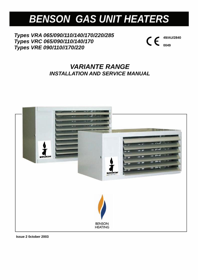
Types VRA 065/090/110/140/170/220/285 Types VRC 065/090/110/140/170 Types VRE 090/110//170/220
VARIANTE RANGE INSTALLATION AND SERVICE MANUAL
Issue 2 0ctober 2003
1
BENSON GAS UNIT HEATERS
49/AU/2840 0049
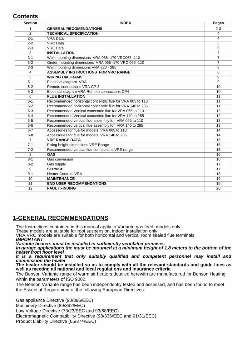
The Instructions contained in this manual apply to Variante gas fired models only. These models are suitable for roof suspension, indoor installation only. VRA VRC models are suitable for both horizontal and vertical room sealed flue terminals IMPORTANT : Variante heaters must be installed in sufficiently ventilated premises In garage applications the must be mounted at a minimum height of 1.8 meters to the bottom of the heater from floor level It is a requirement that only suitably qualified and competent personnel may install and commission the heater The heater should be installed so as to comply with all the relevant standards and guide lines as well as meeting all national and local regulations and insurance criteria The Benson Variante range of warm air heaters detailed herewith are manufactured for Benson Heating within the parameters of ISO 9002. The Benson Variante range has been independently tested and assessed, and has been found to meet the Essential Requirement of the following European Directives: Gas appliance Directive (90/396/EEC) Machinery Directive (89/392/EEC) Low Voltage Directive (73/23/EEC and 93/68/EEC) Electromagnetic Compatibility Directive (98/336/EEC and 91/31/EEC) Product Liability Directive (65/374/EEC)
Contents Section INDEX Pages
1 GENERAL RECOMENDATIONS 2-3 2 TECHNICAL SPECIFICATION 4
2-1 VRA Data 4 2-2 VRC Data 5 2-3 VRE Data 6 3 INSTALLATION 7
3-1 Wall mounting dimensions VRA 065 -170 VRC065 -110 7 3-2 Girder mounting dimensions VRA 065 -170 VRC 065 -110 7 3-3 Wall mounting dimensions VRA 220 - 285 8 4 ASSEMBLY INSTRUCTIONS FOR VRC RANGE 8 5 WIRING DIAGRAMS 9
5-1 Electrical diagram VRA 9 5-2 Remote connections VRA CP 2 10 5-3 Electrical diagram VRA Remote connections CP4 10 6 FLUE INSTALLATION 11
6-1 Recommended horizontal concentric flue for VRA 065 to 110 11 6-2 Recommended horizontal concentric flue for VRA 140 to 285 11 6-3 Recommended Vertical concentric flue for VRA 065 to 110 12 6-4 Recommended Vertical concentric flue for VRA 140 to 285 12 6-5 Recommended vertical flue assembly for VRA 065 to 110 13 6-6 Recommended vertical flue assembly for VRA 140 to 285 13 6-7 Accessories for flue for models VRA 065 to 110 14 6-8 Accessories for flue for models VRA 140 to 285 14 7 VRE RANGE DATA 15
7-1 Fixing height dimensions VRE Range 15 7-2 Recommended vertical flue connections VRE range 15 8 GAS 16
8-1 Gas conversion 16 8-2 Gas supply 17 9 SERVICE 17
9-1 Heater Controls VRA 18 10 MAINTENANCE 19 11 END USER RECOMMENDATIONS 19 12 FAULT FINDING 20
1-GENERAL RECOMMENDATIONS
The manufacturer has taken reasonable and practical steps to ensure that Benson Variante Range of Heaters are safe and without risk when properly used. These heaters should therefore only be used in the manner and purpose for which they were intended, and in accordance with the recommendations detailed herewith. The heaters have been designed, manufactured, assembled, inspected, and tested, with safety and quality in mind, there are certain basic precautions which the installer and user should be aware of, and they are strongly advised to read the appropriate sections of the information pack accompanying the heater, prior to installation or use. Benson Heating supports all new products being supplied to their customers with a comprehensive information pack; this clearly defines mandatory instructions for the safe installation, use, and maintenance, of the appliance(s). Where proprietary items are incorporated into Benson Heating products, detailed information and instructions are also provided as part of the information pack. It is the responsibility of the installer, owner, user, or hirer, of such products supplied by Benson Heating, to en-sure that they are familiar with the appropriate information/manuals, supplied by the manufacturer, and that they are suitably aware of the purpose of the manuals and the safety instructions. In addition, operators must be suitably trained in the use of the appliance so as to ensure its continued safe and efficient use. Benson Heating has a commitment to continuous improvement, and therefore reserves the right to amend or change the specification of the Variante Heater range subject to agreement from The Notified Body. The heater is supplied with a 2 year warranty on all parts. The warranty commences from the date of dispatch from the manufacturer, and is subject to the terms detailed within the manufacturer 'conditions of business'. The warranty may be invalidated if : a) The warranty registration/commissioning card has not been completed and returned to the manufacturer
b) The installation is not in accordance with the general requirements of this manual
c) The flue arrangement and air supply for the heater are not in accordance with the manufacturers
recommendations, codes of practice, or similar standards
d) Air flow through the heater is not in accordance with the manufacturers technical specifications
e) Internal wiring on the heater has been tampered with or unauthorised service/repairs undertaken
f) The main electrical supply input to the heater has been interrupted during the heating mode
g) The heater has been subject to and affected by the ingress of water in any form
h) The heater is not operated at the rating(s) laid down in the manufacturers technical specifications
i) The heater has not been operated or used within the normal scope of its intended application
j) The manufacturer's recommended minimum service requirements have not been complied with
All warranty claims must contain the following information to enable processing to take place; (1) Heater model , (2) Heater serial number (3) Order reference/date of order, together with full installation de-
tails (name and address) (4) Details or symptoms of fault (5) Installers name and address.
Faulty parts must be returned to the manufacturer Spares Department, the address of which is provided on the rear cover of this manual. Any such parts will undergo inspection to verify the claim. Replacement parts supplied prior to this may be charged, and a credit supplied upon subsequent validation of the warranty claim. Consum-able items are specifically not included within the scope of the warranty. Notification is required immediately a fault is suspected. The manufacturer will not accept responsibility for any additional damage that has been caused, expense incurred, or consequential loss resulting from any failure of the heater(s). Any reference made to Laws, Standards, Directives , Codes of Practice or other recommendations governing the application and installation of heating appliances and which may be referred to in Brochures, Specifications, Quotations, and Installation, Operation and Maintenance manuals is done so for information and guidance purposes only and should only be considered valid at the time of the publication. Manufacturer cannot be held responsible from any matters arising from the revision to or introduction of new Laws, Standards, Directives, Codes of Practice or other recommendations.
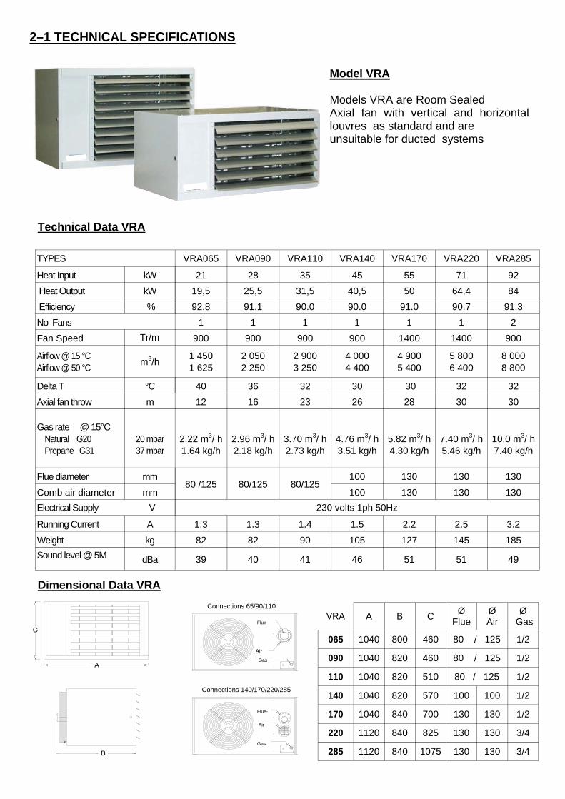
TYPES VRA065 VRA090 VRA110 VRA140 VRA170 VRA220 VRA285
Heat Input kW 21 28 35 45 55 71 92
Heat Output kW 19,5 25,5 31,5 40,5 50 64,4 84
Efficiency % 92.8 91.1 90.0 90.0 91.0 90.7 91.3
No Fans 1 1 1 1 1 1 2
Airflow @ 15 °C Airflow @ 50 °C
m3/h 1 450 1 625
2 050 2 250
2 900 3 250
4 000 4 400
4 900 5 400
5 800 6 400
8 000 8 800
Delta T °C 40 36 32 30 30 32 32
Axial fan throw m 12 16 23 26 28 30 30
Gas rate @ 15°C Natural G20 Propane G31
20 mbar 37 mbar
2.22 m3/ h 1.64 kg/h
2.96 m3/ h 2.18 kg/h
3.70 m3/ h 2.73 kg/h
4.76 m3/ h 3.51 kg/h
5.82 m3/ h 4.30 kg/h
7.40 m3/ h 5.46 kg/h
10.0 m3/ h 7.40 kg/h
Flue diameter mm 80 /125 80/125
100 130 130 130
Comb air diameter mm 100 130 130 130
Electrical Supply V 230 volts 1ph 50Hz
Running Current A 1.3 1.3 1.4 1.5 2.2 2.5 3.2
Weight kg 82 82 90 105 127 145 185
Sound level @ 5M dBa 39 40 41 46 51 51 49
80/125
Fan Speed 900 900 900 900 1400 1400 900 Tr/m
Technical Data VRA
Dimensional Data VRA
Model VRA Models VRA are Room Sealed Axial fan with vertical and horizontal louvres as standard and are unsuitable for ducted systems
VRA A B C Ø
Flue Ø Air
Ø Gas
065 1040 800 460 80 / 125 1/2
090 1040 820 460 80 / 125 1/2
110 1040 820 510 1/2
140 1040 820 570 100 100 1/2
170 1040 840 700 130 130 1/2
220 1120 840 825 130 130 3/4
285 1120 840 1075 130 130 3/4
80 / 125
2–1 TECHNICAL SPECIFICATIONS
Connections 140/170/220/285
Flue-
Gas
Air
Connections 65/90/110
Flue
Gas
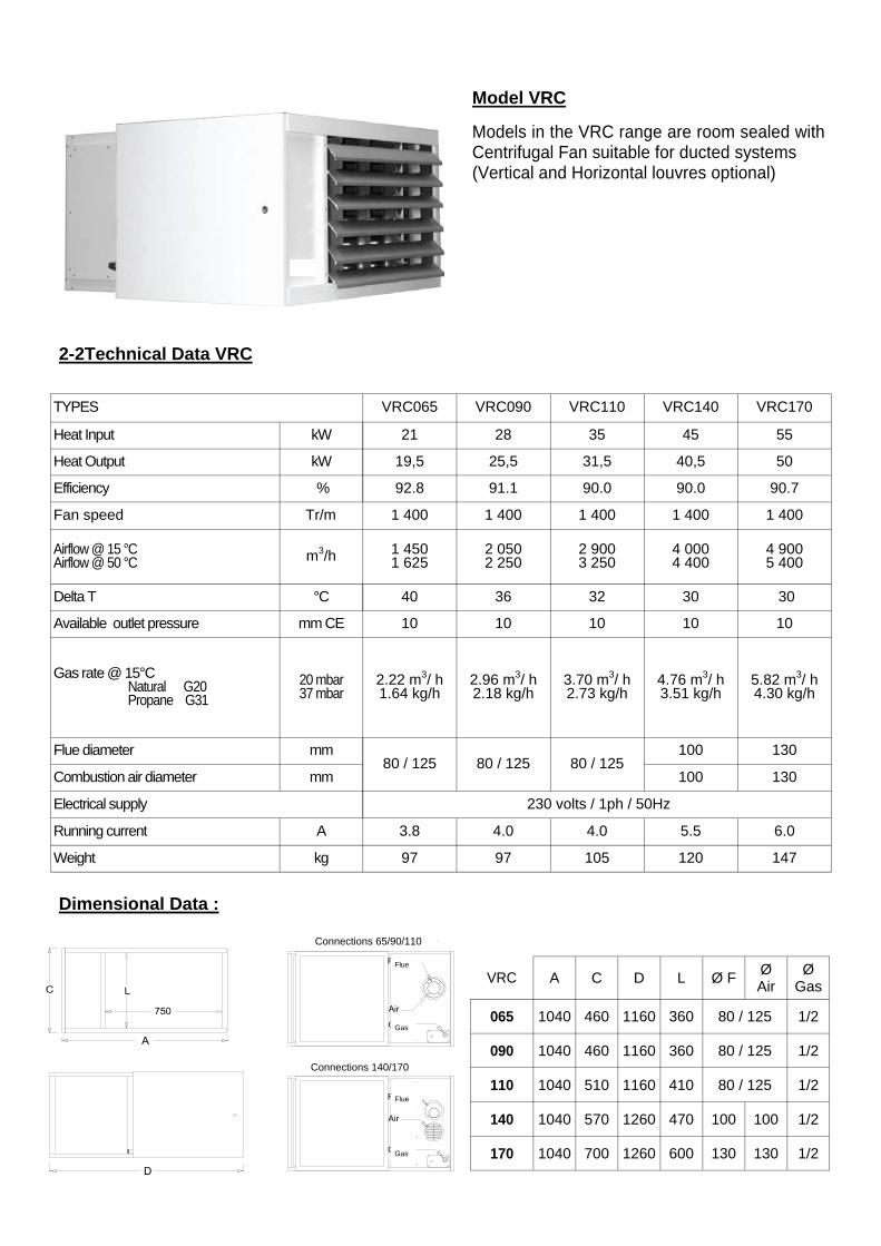
2-2Technical Data VRC
Dimensional Data :
TYPES VRC065 VRC090 VRC110 VRC140 VRC170
Heat Input kW 21 28 35 45 55
Heat Output kW 19,5 25,5 31,5 40,5 50
Efficiency % 92.8 91.1 90.0 90.0 90.7
Fan speed Tr/m 1 400 1 400 1 400 1 400 1 400
Airflow @ 15 °C Airflow @ 50 °C m3/h 1 450
1 625 2 050 2 250
2 900 3 250
4 000 4 400
4 900 5 400
Delta T °C 40 36 32 30 30
Available outlet pressure mm CE 10 10 10 10 10
Gas rate @ 15°C Natural G20 Propane G31
20 mbar 37 mbar
2.22 m3/ h 1.64 kg/h
2.96 m3/ h 2.18 kg/h
3.70 m3/ h 2.73 kg/h
4.76 m3/ h 3.51 kg/h
5.82 m3/ h 4.30 kg/h
Flue diameter mm 80 / 125 80 / 125 80 / 125
100 130
Combustion air diameter mm 100 130
Electrical supply 230 volts / 1ph / 50Hz
Running current A 3.8 4.0 4.0 5.5 6.0
Weight kg 97 97 105 120 147
Model VRC
Models in the VRC range are room sealed with Centrifugal Fan suitable for ducted systems (Vertical and Horizontal louvres optional)
VRC A C D L Ø F Ø Air
Ø Gas
065 1040 460 1160 360 80 / 125 1/2
090 1040 460 1160 360 80 / 125 1/2
110 1040 510 1160 410 80 / 125 1/2
140 1040 570 1260 470 100 100 1/2
170 1040 700 1260 600 130 130 1/2
Connections 65/90/110
Connections 140/170
Flue
Flue
Gas
Gas
Dimensional Data
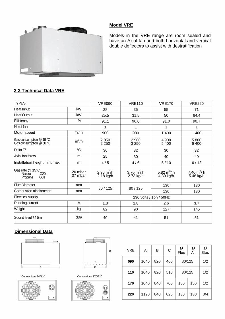
2-3 Technical Data VRE
TYPES VRE090 VRE110 VRE170 VRE220
Heat Input kW 28 35 55 71
Heat Output kW 25,5 31,5 50 64,4
Efficiency % 91.1 90.0 91.0 90.7
No of fans 1 1 1 1
Motor speed Tr/m 900 900 1 400 1 400
Gas consumption @ 15 °C Gas consumption @ 50 °C m3/h 2 050
2 250 2 900 3 250
4 900 5 400
5 800 6 400
Delta T° °C 36 32 30 32
Axial fan throw m
Installation height mini/maxi m 4 / 5 4 / 6 5 / 10 6 / 12
Gas rate @ 15°C Natural G20 Propane G31
20 mbar 37 mbar
2.96 m3/h 2.18 kg/h
3.70 m3/ h 2.73 kg/h
5.82 m3/ h 4.30 kg/h
7.40 m3/ h 5.46 kg/h
Flue Diameter mm 80 / 125 80 / 125
130 130
Combustion air diameter mm 130 130
Electrical supply 230 volts / 1ph / 50Hz
Running current A 1.3 1.8 2.6 3.7
Weight kg 82 90 127 145
Sound level @ 5m dBa 40 41 51 51
25 30 40 40
Model VRE Models in the VRE range are room sealed and have an Axial fan and both horizontal and vertical double deflectors to assist with destratification
VRE A B C Ø
Flue Ø Air
Ø Gas
090 1040 820 460 80/125 1/2
110 1040 820 510 1/2
170 1040 840 700 130 130 1/2
220 1120 840 825 130 130 3/4
80/125 Connections 170/220 Connections 90/110
3– INSTALLATION OF HEATERS
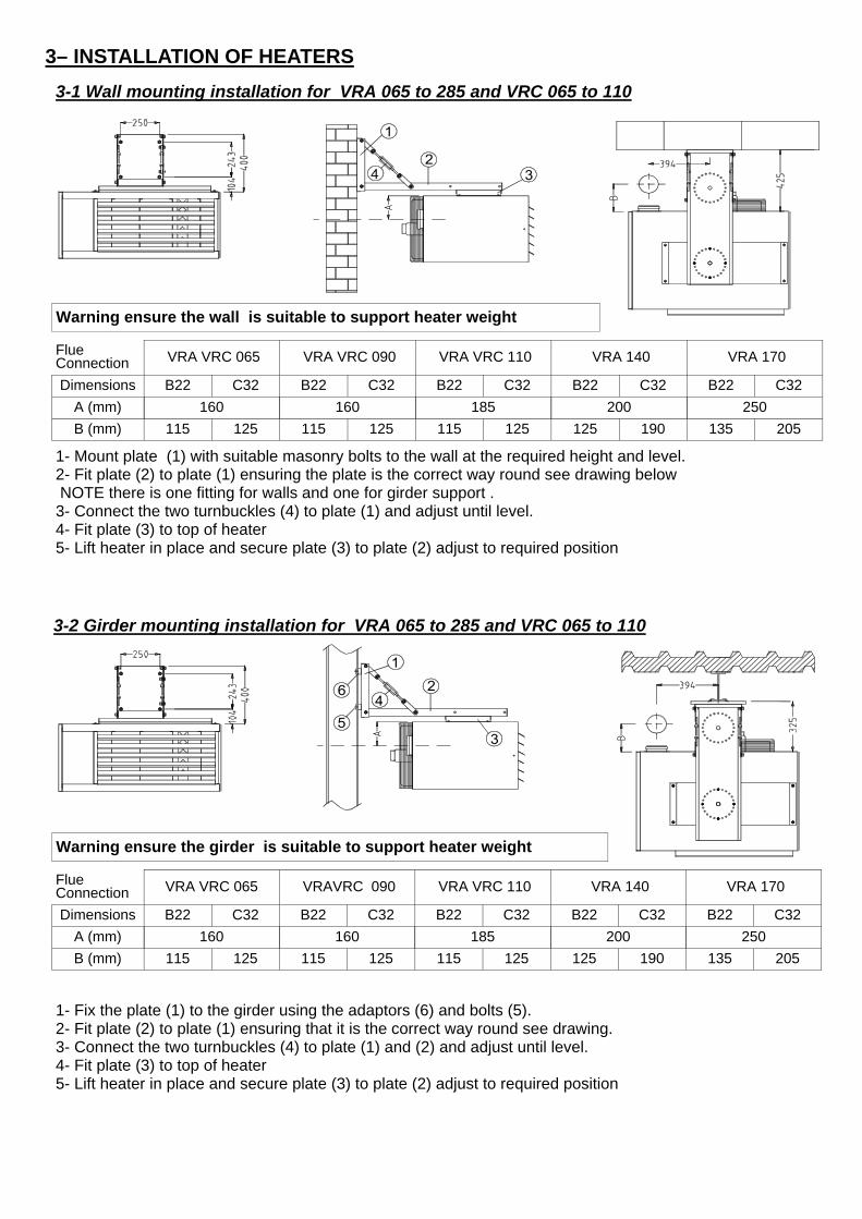
3-1 Wall mounting installation for VRA 065 to 285 and VRC 065 to 110
3-2 Girder mounting installation for VRA 065 to 285 and VRC 065 to 110
1- Mount plate (1) with suitable masonry bolts to the wall at the required height and level. 2- Fit plate (2) to plate (1) ensuring the plate is the correct way round see drawing below NOTE there is one fitting for walls and one for girder support . 3- Connect the two turnbuckles (4) to plate (1) and adjust until level. 4- Fit plate (3) to top of heater 5- Lift heater in place and secure plate (3) to plate (2) adjust to required position
1- Fix the plate (1) to the girder using the adaptors (6) and bolts (5). 2- Fit plate (2) to plate (1) ensuring that it is the correct way round see drawing. 3- Connect the two turnbuckles (4) to plate (1) and (2) and adjust until level. 4- Fit plate (3) to top of heater 5- Lift heater in place and secure plate (3) to plate (2) adjust to required position
Warning ensure the girder is suitable to support heater weight
Warning ensure the wall is suitable to support heater weight
Flue Connection VRA VRC 065 VRA VRC 090 VRA VRC 110 VRA 140 VRA 170
Dimensions B22 C32 B22 C32 B22 C32 B22 C32 B22 C32
A (mm) 160 160 185 200
B (mm) 115 125 115 125 115 125 125 190 135 205
250
Flue Connection VRA VRC 065 VRAVRC 090 VRA VRC 110 VRA 140 VRA 170
Dimensions B22 C32 B22 C32 B22 C32 B22 C32 B22 C32
A (mm) 160 160 185 200
B (mm) 115 125 115 125 115 125 125 190 135 205
250
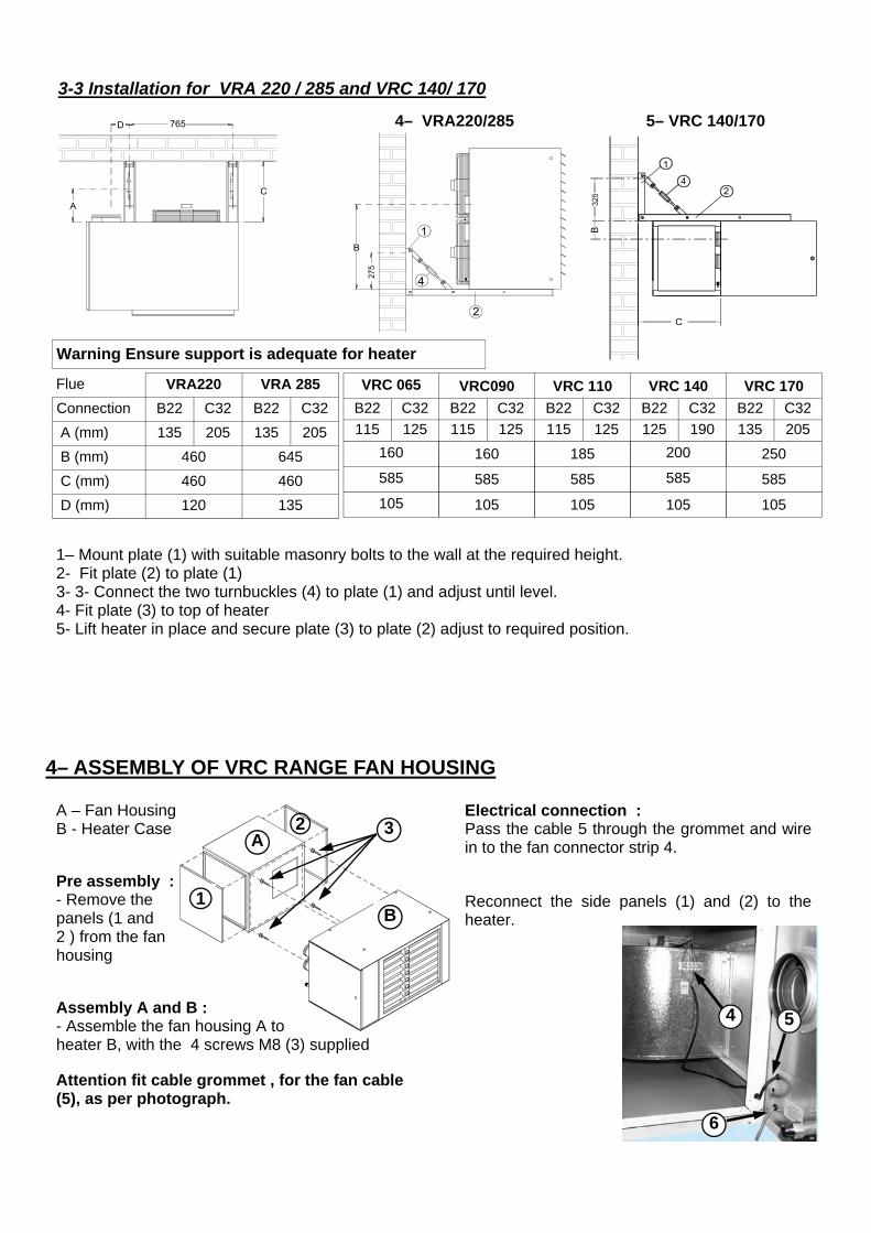
3-3 Installation for VRA 220 / 285 and VRC 140/ 170
1– Mount plate (1) with suitable masonry bolts to the wall at the required height. 2- Fit plate (2) to plate (1) 3- 3- Connect the two turnbuckles (4) to plate (1) and adjust until level. 4- Fit plate (3) to top of heater 5- Lift heater in place and secure plate (3) to plate (2) adjust to required position.
4– ASSEMBLY OF VRC RANGE FAN HOUSING
Electrical connection : Pass the cable 5 through the grommet and wire in to the fan connector strip 4. Reconnect the side panels (1) and (2) to the heater.
A – Fan Housing B - Heater Case Pre assembly : - Remove the panels (1 and 2 ) from the fan housing Assembly A and B : - Assemble the fan housing A to heater B, with the 4 screws M8 (3) supplied Attention fit cable grommet , for the fan cable (5), as per photograph.
A
1
2
B
3
4 5
6
Flue VRA220 VRA 285
Connection B22 C32 B22 C32
A (mm) 135 205 135 205
B (mm) 460 645
C (mm) 460 460
D (mm) 120 135
4– VRA220/285 5– VRC 140/170
Warning Ensure support is adequate for heater
VRC 065 VRC090 VRC 110 VRC 140 VRC 170
B22 C32 B22 C32 B22 C32 B22 C32 B22 C32
115 125 115 125 115 125 125 190 135 205
160 160 185 200 250
585 585 585 585 585
105 105 105 105 105
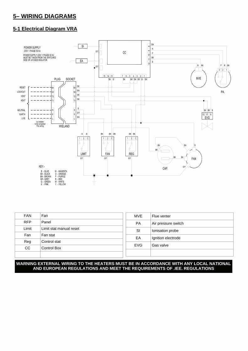
5-1 Electrical Diagram VRA
5– WIRING DIAGRAMS
WARNING EXTERNAL WIRING TO THE HEATERS MUST BE IN ACCORDANCE WITH ANY LOCAL NATIONAL AND EUROPEAN REGULATIONS AND MEET THE REQUIREMENTS OF .IEE. REGULATIONS
FAN Fan
RFP Panel
Limit Limit stat manual reset
Fan Fan stat
Reg Control stat
CC Control Box
MVE Flue venter
PA Air pressure switch
SI Ionisation probe
EA Ignition electrode
EVG Gas valve
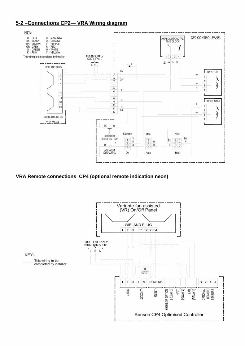
5-2 –Connections CP2— VRA Wiring diagram
VRA Remote connections CP4 (optional remote indication neon)
VRA MK 11
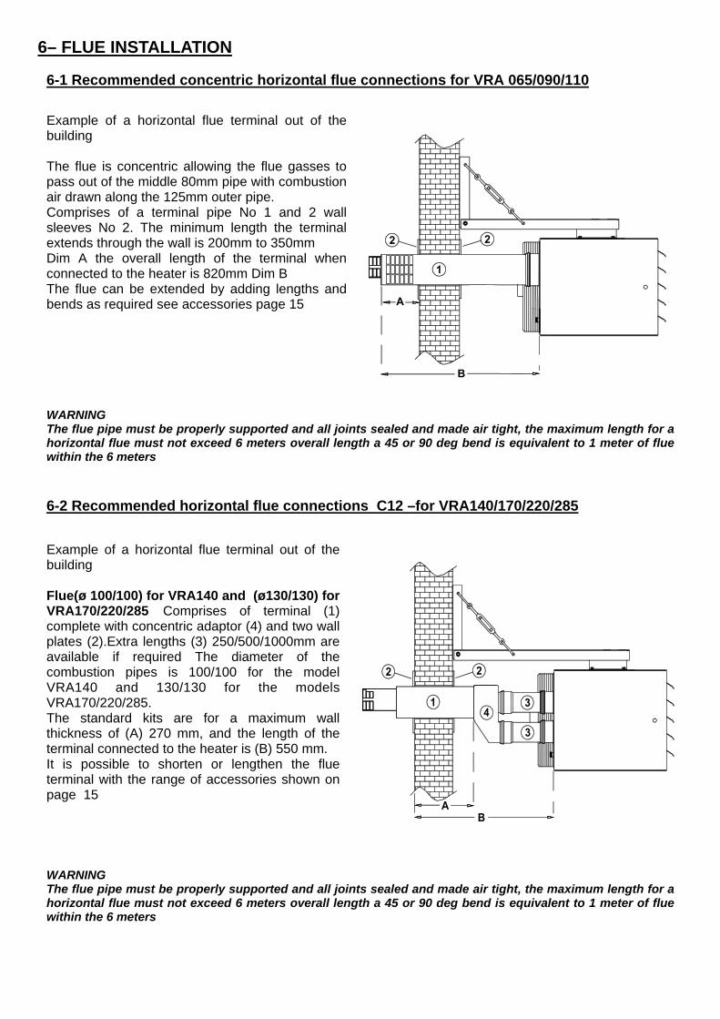
Example of a horizontal flue terminal out of the building Flue(ø 100/100) for VRA140 and (ø130/130) for VRA170/220/285 Comprises of terminal (1) complete with concentric adaptor (4) and two wall plates (2).Extra lengths (3) 250/500/1000mm are available if required The diameter of the combustion pipes is 100/100 for the model VRA140 and 130/130 for the models VRA170/220/285. The standard kits are for a maximum wall thickness of (A) 270 mm, and the length of the terminal connected to the heater is (B) 550 mm. It is possible to shorten or lengthen the flue terminal with the range of accessories shown on page 15
Example of a horizontal flue terminal out of the building The flue is concentric allowing the flue gasses to pass out of the middle 80mm pipe with combustion air drawn along the 125mm outer pipe. Comprises of a terminal pipe No 1 and 2 wall sleeves No 2. The minimum length the terminal extends through the wall is 200mm to 350mm Dim A the overall length of the terminal when connected to the heater is 820mm Dim B The flue can be extended by adding lengths and bends as required see accessories page 15
6-1 Recommended concentric horizontal flue connections for VRA 065/090/110
WARNING The flue pipe must be properly supported and all joints sealed and made air tight, the maximum length for a horizontal flue must not exceed 6 meters overall length a 45 or 90 deg bend is equivalent to 1 meter of flue within the 6 meters
6– FLUE INSTALLATION
6-2 Recommended horizontal flue connections C12 –for VRA140/170/220/285
WARNING The flue pipe must be properly supported and all joints sealed and made air tight, the maximum length for a horizontal flue must not exceed 6 meters overall length a 45 or 90 deg bend is equivalent to 1 meter of flue within the 6 meters
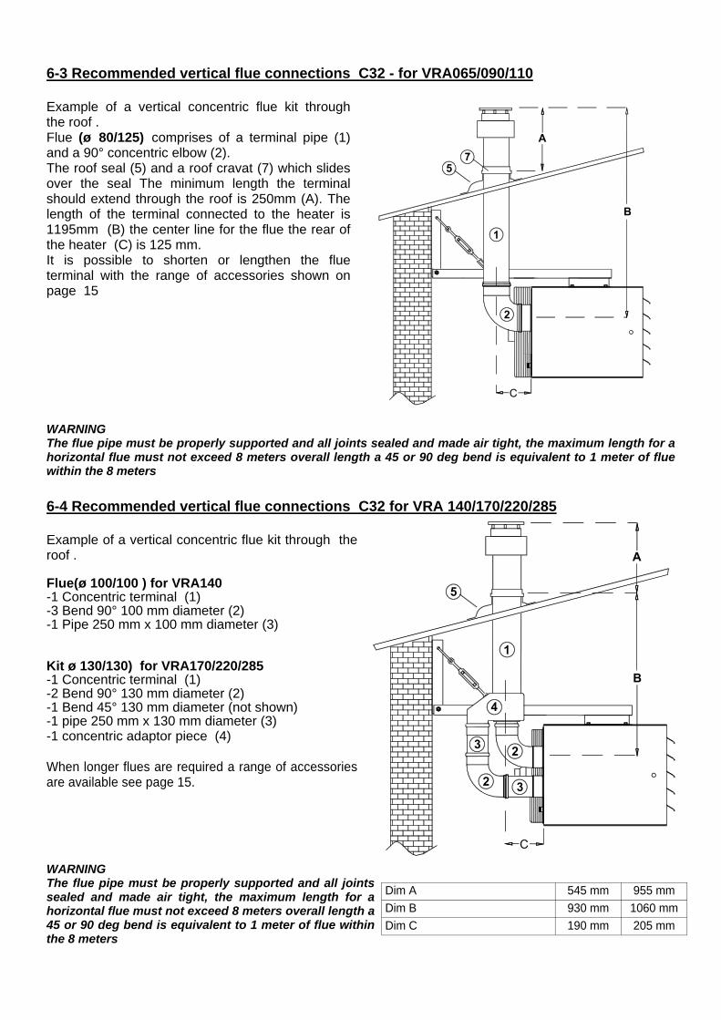
Example of a vertical concentric flue kit through the roof . Flue (ø 80/125) comprises of a terminal pipe (1) and a 90° concentric elbow (2). The roof seal (5) and a roof cravat (7) which slides over the seal The minimum length the terminal should extend through the roof is 250mm (A). The length of the terminal connected to the heater is 1195mm (B) the center line for the flue the rear of the heater (C) is 125 mm. It is possible to shorten or lengthen the flue terminal with the range of accessories shown on page 15
6-3 Recommended vertical flue connections C32 - for VRA065/090/110
WARNING The flue pipe must be properly supported and all joints sealed and made air tight, the maximum length for a horizontal flue must not exceed 8 meters overall length a 45 or 90 deg bend is equivalent to 1 meter of flue within the 8 meters
Example of a vertical concentric flue kit through the roof . Flue(ø 100/100 ) for VRA140 -1 Concentric terminal (1) -3 Bend 90° 100 mm diameter (2) -1 Pipe 250 mm x 100 mm diameter (3) Kit ø 130/130) for VRA170/220/285 -1 Concentric terminal (1) -2 Bend 90° 130 mm diameter (2) -1 Bend 45° 130 mm diameter (not shown) -1 pipe 250 mm x 130 mm diameter (3) -1 concentric adaptor piece (4) When longer flues are required a range of accessories are available see page 15.
WARNING The flue pipe must be properly supported and all joints sealed and made air tight, the maximum length for a horizontal flue must not exceed 8 meters overall length a 45 or 90 deg bend is equivalent to 1 meter of flue within the 8 meters
6-4 Recommended vertical flue connections C32 for VRA 140/170/220/285
Dim A 545 mm 955 mm
Dim B 930 mm 1060 mm
Dim C 190 mm 205 mm
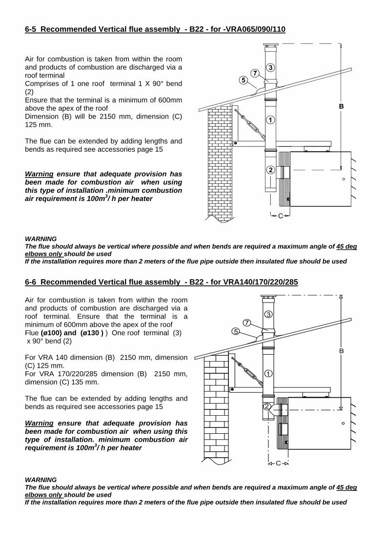
Air for combustion is taken from within the room and products of combustion are discharged via a roof terminal Comprises of 1 one roof terminal 1 X 90° bend (2) Ensure that the terminal is a minimum of 600mm above the apex of the roof Dimension (B) will be 2150 mm, dimension (C) 125 mm. The flue can be extended by adding lengths and bends as required see accessories page 15 Warning ensure that adequate provision has been made for combustion air when using this type of installation .minimum combustion air requirement is 100m3/ h per heater
WARNING The flue should always be vertical where possible and when bends are required a maximum angle of 45 deg elbows only should be used If the installation requires more than 2 meters of the flue pipe outside then insulated flue should be used
6-5 Recommended Vertical flue assembly - B22 - for -VRA065/090/110
Air for combustion is taken from within the room and products of combustion are discharged via a roof terminal. Ensure that the terminal is a minimum of 600mm above the apex of the roof Flue (ø100) and (ø130 ) ) One roof terminal (3) x 90° bend (2) For VRA 140 dimension (B) 2150 mm, dimension (C) 125 mm. For VRA 170/220/285 dimension (B) 2150 mm, dimension (C) 135 mm. The flue can be extended by adding lengths and bends as required see accessories page 15 Warning ensure that adequate provision has been made for combustion air when using this type of installation. minimum combustion air requirement is 100m3/ h per heater
WARNING The flue should always be vertical where possible and when bends are required a maximum angle of 45 deg elbows only should be used If the installation requires more than 2 meters of the flue pipe outside then insulated flue should be used
6-6 Recommended Vertical flue assembly - B22 - for VRA140/170/220/285
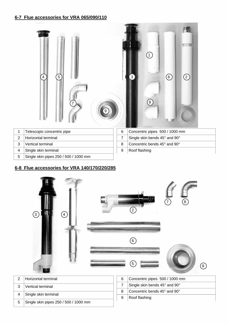
6-7 Flue accessories for VRA 065/090/110
6 Concentric pipes 500 / 1000 mm
7 Single skin bends 45° and 90°
8 Concentric bends 45° and 90°
9 Roof flashing
4 3 2 6 5
7
10
9
8
1
6-8 Flue accessories for VRA 140/170/220/285
4 3 2
6
5
7
10
9
8
2 Horizontal terminal
3 Vertical terminal
4 Single skin terminal
5 Single skin pipes 250 / 500 / 1000 mm
6 Concentric pipes 500 / 1000 mm
7 Single skin bends 45° and 90°
8 Concentric bends 45° and 90°
9 Roof flashing
1 Telescopic concentric pipe
2 Horizontal terminal
3 Vertical terminal
4 Single skin terminal
5 Single skin pipes 250 / 500 / 1000 mm
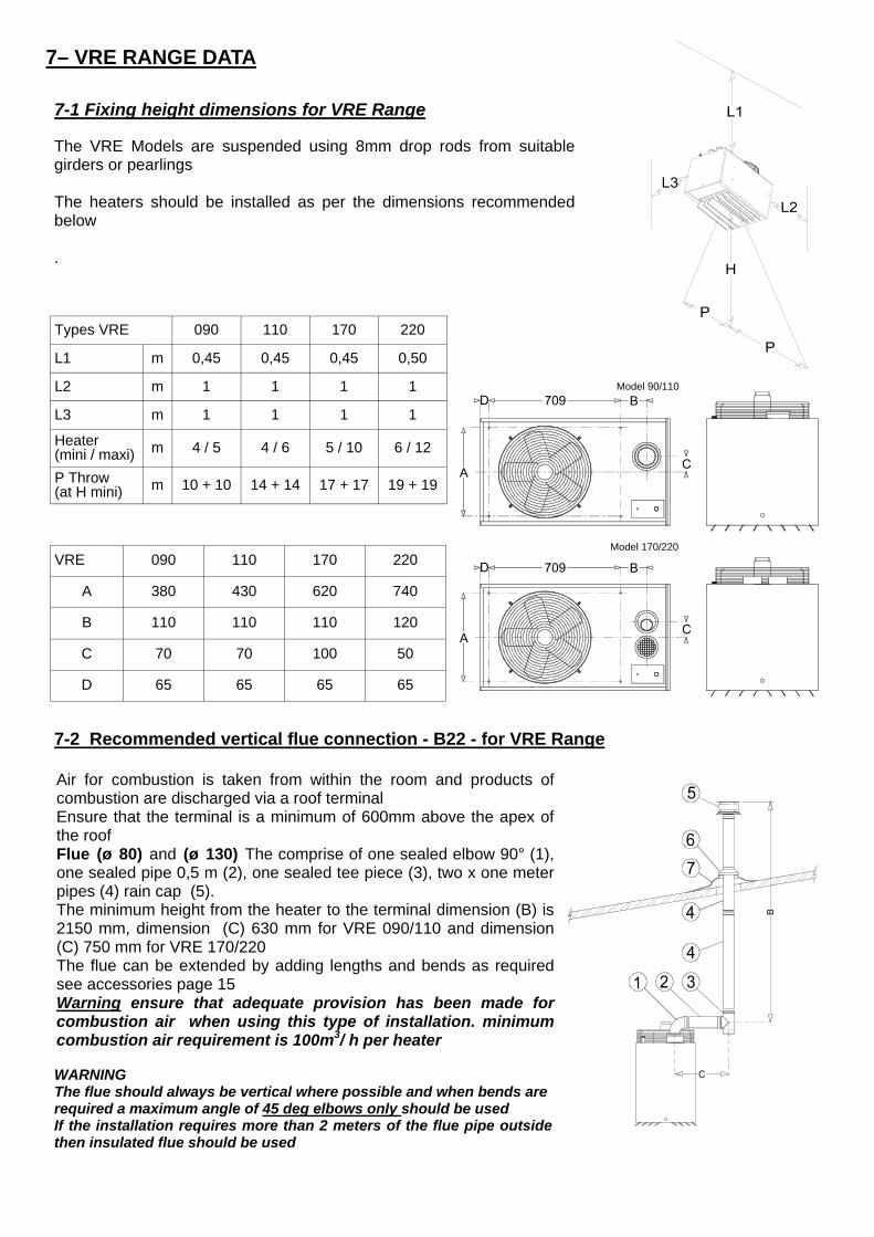
Air for combustion is taken from within the room and products of combustion are discharged via a roof terminal Ensure that the terminal is a minimum of 600mm above the apex of the roof Flue (ø 80) and (ø 130) The comprise of one sealed elbow 90° (1), one sealed pipe 0,5 m (2), one sealed tee piece (3), two x one meter pipes (4) rain cap (5). The minimum height from the heater to the terminal dimension (B) is 2150 mm, dimension (C) 630 mm for VRE 090/110 and dimension (C) 750 mm for VRE 170/220 The flue can be extended by adding lengths and bends as required see accessories page 15 Warning ensure that adequate provision has been made for combustion air when using this type of installation. minimum combustion air requirement is 100m3/ h per heater
7-2 Recommended vertical flue connection - B22 - for VRE Range
WARNING The flue should always be vertical where possible and when bends are required a maximum angle of 45 deg elbows only should be used If the installation requires more than 2 meters of the flue pipe outside then insulated flue should be used
7-1 Fixing height dimensions for VRE Range
VRE 090 110 170 220
A 380 430 620 740
B 110 110 110 120
C 70 70 100 50
D 65 65 65 65
The VRE Models are suspended using 8mm drop rods from suitable girders or pearlings The heaters should be installed as per the dimensions recommended below .
090 110 170 220
L1 m 0,45 0,45 0,45 0,50
L2 m 1 1 1 1
L3 m 1 1 1 1
Heater(mini / maxi) m 4 / 5 4 / 6 5 / 10 6 / 12
Types VRE
P Throw (at H mini) m 10 + 10 14 + 14 17 + 17 19 + 19
7– VRE RANGE DATA
Model 90/110
Model 170/220
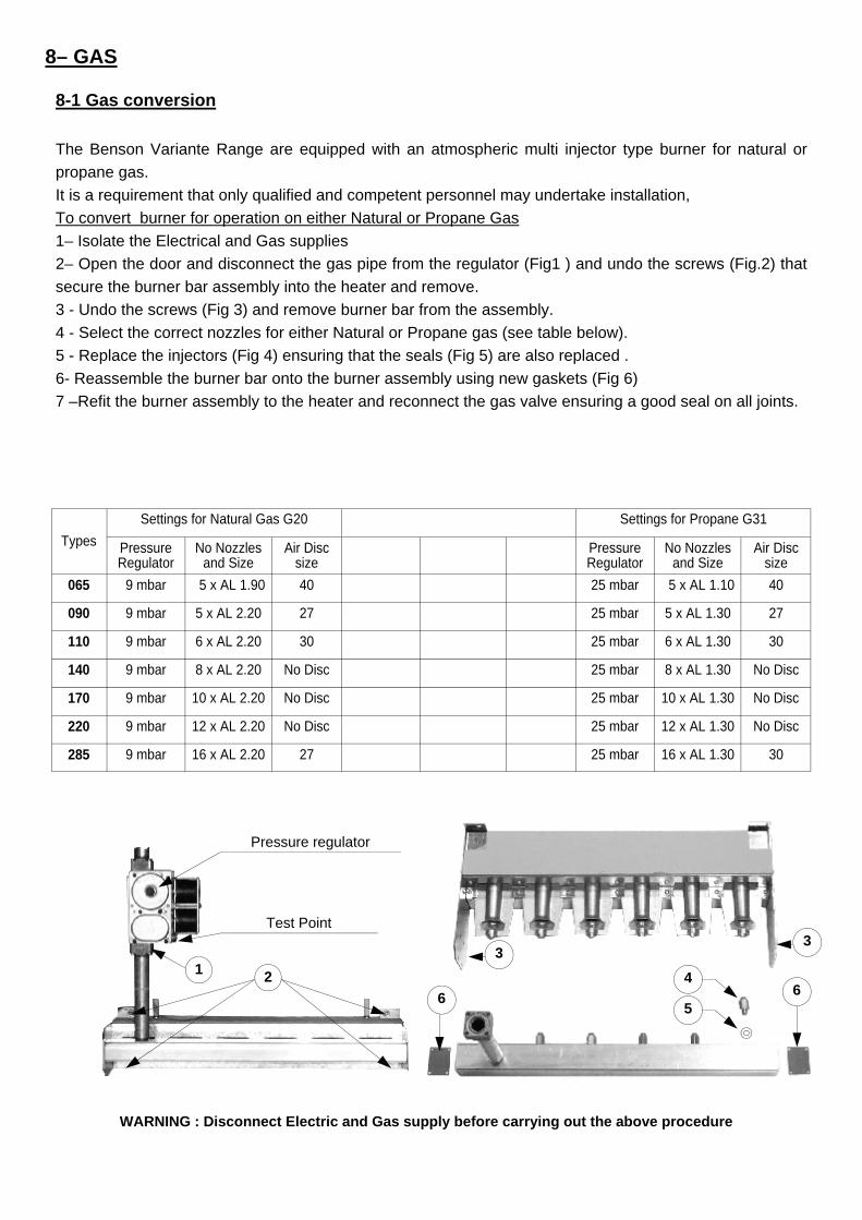
WARNING : Disconnect Electric and Gas supply before carrying out the above procedure
8-1 Gas conversion
The Benson Variante Range are equipped with an atmospheric multi injector type burner for natural or
propane gas.
It is a requirement that only qualified and competent personnel may undertake installation,
To convert burner for operation on either Natural or Propane Gas
1– Isolate the Electrical and Gas supplies
2– Open the door and disconnect the gas pipe from the regulator (Fig1 ) and undo the screws (Fig.2) that
secure the burner bar assembly into the heater and remove.
3 - Undo the screws (Fig 3) and remove burner bar from the assembly.
4 - Select the correct nozzles for either Natural or Propane gas (see table below).
5 - Replace the injectors (Fig 4) ensuring that the seals (Fig 5) are also replaced .
6- Reassemble the burner bar onto the burner assembly using new gaskets (Fig 6)
7 –Refit the burner assembly to the heater and reconnect the gas valve ensuring a good seal on all joints.
8– GAS
Settings for Natural Gas G20 Settings for Propane G31
Pressure Regulator
No Nozzles and Size
Air Disc size
Pressure Regulator
No Nozzles and Size
Air Disc size
065 9 mbar 5 x AL 1.90 40 25 mbar 5 x AL 1.10 40
090 9 mbar 5 x AL 2.20 27 25 mbar 5 x AL 1.30 27
110 9 mbar 6 x AL 2.20 30 25 mbar 6 x AL 1.30 30
140 9 mbar 8 x AL 2.20 No Disc 25 mbar 8 x AL 1.30 No Disc
170 9 mbar 10 x AL 2.20 No Disc 25 mbar 10 x AL 1.30 No Disc
220 9 mbar 12 x AL 2.20 No Disc 25 mbar 12 x AL 1.30 No Disc
285 9 mbar 16 x AL 2.20 27 25 mbar 16 x AL 1.30 30
Types
4
5
3 3
6 6
Pressure regulator
1
Test Point
2
9- SERVICE Warning It is a requirement that only qualified and competent personnel may undertake servicing and commissioning On completion of service details should be entered in the heater log book
8-2 Gas supply WARNING Installers should satisfy themselves that the gas pipework installation is carried out in accordance with all current legislation, Codes of Practice and Recommendations. Additionally it may be necessary to protect the gas valves which form part of the heater or burner assembly from potential pipe contamination particularly, but not exclusively, where copper pipe is used. In instances where copper pipework is to be used for all or part of a gas pipework installation, including short length final connections then we advise that installers consult with gas supplier or provider and satisfy themselves what additional precautions may be necessary . Consideration should be given to the pressure drop on single and multi heater installations and the effect they may have on other plant sharing the supply. As there have been recorded instances of the deposition of copper sulphide dust within the valves and orifices of gas appliances as a direct result of a reaction between the hydrogen sulphide contained in some natural gasses and copper pipe we recommend that the heater(s) should not be connected to any natural gas pipe distribution system which utilizes copper pipework, including final connections. Instead steel pipework should be used throughout. In the event that it is impractical to use steel pipework or where installers are obliged or insist on using elements of copper pipework within the installation then we strongly recommend that the gas supplier be consulted as specific conditions and requirements may be necessary. Only qualified and competent personnel are allowed to undertake the installation, commissioning, and servicing of Gas Heaters Prior to installation the supply characteristics (gas type and pressure) must be checked to ensure that they are in accordance with the data plate on the heater. The gas supplier should check that the meter and service connection to the heater are capable of delivering the required volume of gas, thereby ensuring that the minimum burner pressure can be achieved. If it is necessary to fit a gas pressure booster, the controls must include a low pressure cutoff switch which must be fitted on the supply / inlet side of the booster. It is also a requirement that the gas supplier is advised prior to the installation or fitting of the booster. Each heater supply must be fitted with a separate isolating cock positioned adjacent to and upstream of the union which must be sited outside the heater. The isolating cock should be of the 900 turn type and should be clearly marked OPEN / CLOSED it should also be installed so as to fall to the closed position An approved gas jointing compound must be used on all joints and unions and the system purged and tested for soundness prior to final connection The connection to the heater can be made by way of either an approved flexible coupling or rigid connection . Threaded connections must comply to ISO 288/1 or ISO 7/1 further information concerning accepted European practice is detailed in BS EN1020 1998. The diameter of the pipework from the isolating cock to the burner must not be less than the diameter of the connection into the heater Reference to The Institute of Gas Engineers publications Utilisation Procedures IGE/UP1 and IGE/UP2 together with reference to BS6891 is strongly advised.
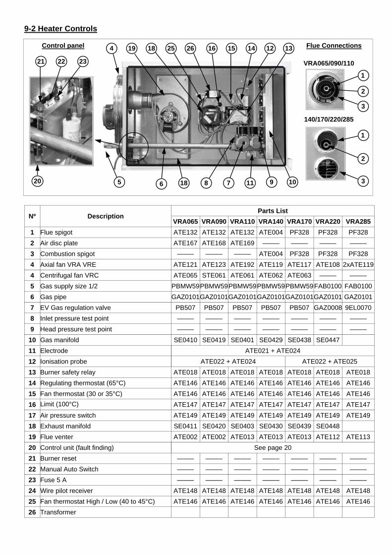
9-2 Heater Controls
Nº Description Parts List
VRA065 VRA090 VRA110 VRA140 VRA170 VRA220 VRA285
1 Flue spigot ATE132 ATE132 ATE132 ATE004 PF328 PF328 PF328
2 Air disc plate ATE167 ATE168 ATE169 ——– ——– ——– ——–
3 Combustion spigot ——– ——– ——– ATE004 PF328 PF328 PF328
4 Axial fan VRA VRE ATE121 ATE123 ATE192 ATE119 ATE117 ATE108 2xATE119
4 Centrifugal fan VRC ATE065 STE061 ATE061 ATE062 ATE063 ——– ——–
5 Gas supply size 1/2 PBMW59 PBMW59 PBMW59 PBMW59 PBMW59 FAB0100 FAB0100
6 Gas pipe GAZ0101 GAZ0101 GAZ0101 GAZ0101 GAZ0101 GAZ0101 GAZ0101
7 EV Gas regulation valve PB507 PB507 PB507 PB507 PB507 GAZ0008 9EL0070
8 Inlet pressure test point ——– ——– ——– ——– ——– ——– ——–
9 Head pressure test point ——– ——– ——– ——– ——– ——– ——–
10 Gas manifold SE0410 SE0419 SE0401 SE0429 SE0438 SE0447
11 Electrode ATE021 + ATE024
12 Ionisation probe ATE022 + ATE024 ATE022 + ATE025
13 Burner safety relay ATE018 ATE018 ATE018 ATE018 ATE018 ATE018 ATE018
14 Regulating thermostat (65°C) ATE146 ATE146 ATE146 ATE146 ATE146 ATE146 ATE146
15 Fan thermostat (30 or 35°C) ATE146 ATE146 ATE146 ATE146 ATE146 ATE146 ATE146
16 Limit (100°C) ATE147 ATE147 ATE147 ATE147 ATE147 ATE147 ATE147
17 Air pressure switch ATE149 ATE149 ATE149 ATE149 ATE149 ATE149 ATE149
18 Exhaust manifold SE0411 SE0420 SE0403 SE0430 SE0439 SE0448
19 Flue venter ATE002 ATE002 ATE013 ATE013 ATE013 ATE112 ATE113
20 Control unit (fault finding)
21 Burner reset ——– ——– ——– ——– ——– ——– ——–
22 Manual Auto Switch ——– ——– ——– ——– ——– ——– ——–
23 Fuse 5 A ——– ——– ——– ——– ——– ——– ——–
24 Wire pilot receiver ATE148 ATE148 ATE148 ATE148 ATE148 ATE148 ATE148
25 Fan thermostat High / Low (40 to 45°C) ATE146 ATE146 ATE146 ATE146 ATE146 ATE146 ATE146
26 Transformer
See page 20
1
2
3 20
21 22 23
5
Control panel
140/170/220/285
Flue Connections
VRA065/090/110
1
2
3
13 12 18 25 14 15 4 16 26 19
10 11 9 7 8 18 6
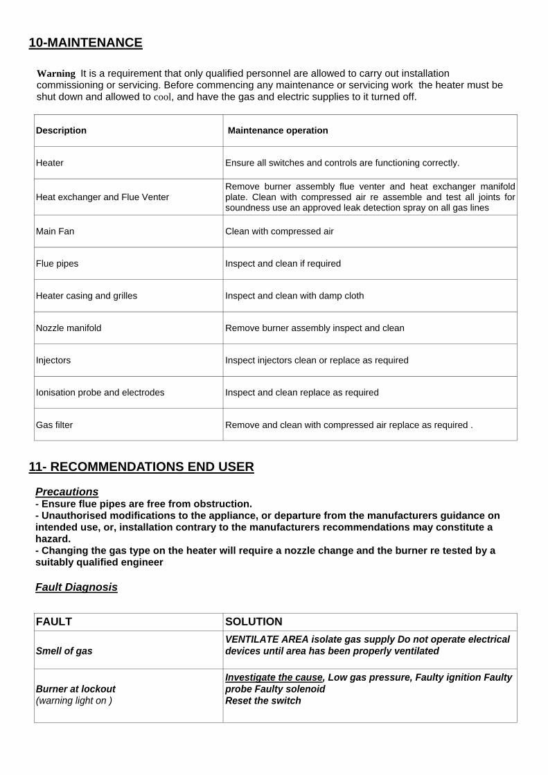
Warning It is a requirement that only qualified personnel are allowed to carry out installation commissioning or servicing. Before commencing any maintenance or servicing work the heater must be shut down and allowed to cool, and have the gas and electric supplies to it turned off.
Description Maintenance operation
Heater Ensure all switches and controls are functioning correctly.
Heat exchanger and Flue Venter Remove burner assembly flue venter and heat exchanger manifold plate. Clean with compressed air re assemble and test all joints for soundness use an approved leak detection spray on all gas lines
Main Fan Clean with compressed air
Flue pipes Inspect and clean if required
Heater casing and grilles Inspect and clean with damp cloth
Nozzle manifold Remove burner assembly inspect and clean
Injectors Inspect injectors clean or replace as required
Ionisation probe and electrodes Inspect and clean replace as required
Gas filter Remove and clean with compressed air replace as required .
10-MAINTENANCE
11- RECOMMENDATIONS END USER
FAULT SOLUTION
Smell of gas
VENTILATE AREA isolate gas supply Do not operate electrical devices until area has been properly ventilated
Burner at lockout (warning light on )
Investigate the cause, Low gas pressure, Faulty ignition Faulty probe Faulty solenoid Reset the switch
Precautions - Ensure flue pipes are free from obstruction. - Unauthorised modifications to the appliance, or departure from the manufacturers guidance on intended use, or, installation contrary to the manufacturers recommendations may constitute a hazard. - Changing the gas type on the heater will require a nozzle change and the burner re tested by a suitably qualified engineer Fault Diagnosis
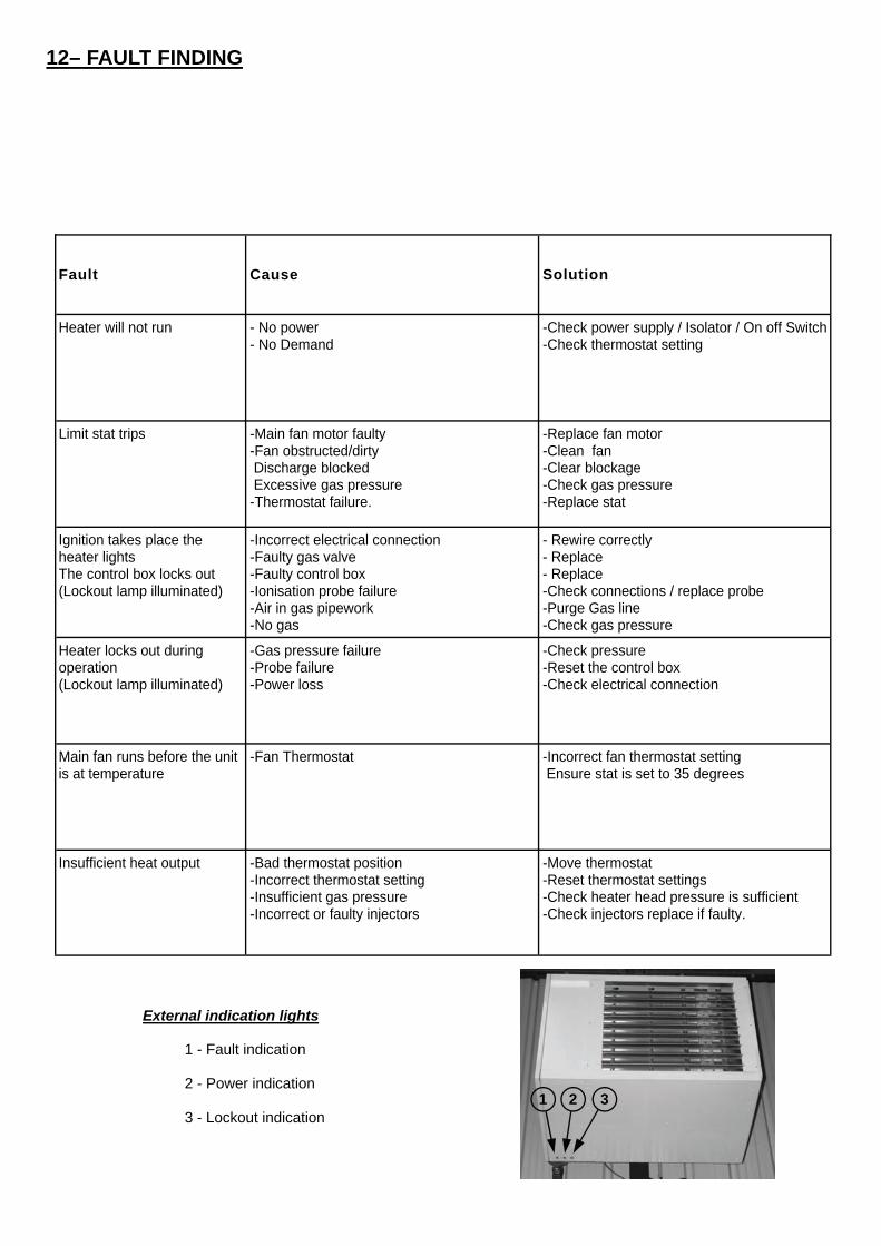
Fault Cause Solution
Heater will not run - No power - No Demand
-Check power supply / Isolator / On off Switch -Check thermostat setting
Limit stat trips -Main fan motor faulty -Fan obstructed/dirty Discharge blocked Excessive gas pressure -Thermostat failure.
-Replace fan motor -Clean fan -Clear blockage -Check gas pressure -Replace stat
Ignition takes place the heater lights The control box locks out (Lockout lamp illuminated)
-Incorrect electrical connection -Faulty gas valve -Faulty control box -Ionisation probe failure -Air in gas pipework -No gas
- Rewire correctly - Replace - Replace -Check connections / replace probe -Purge Gas line -Check gas pressure
Heater locks out during operation (Lockout lamp illuminated)
-Gas pressure failure -Probe failure -Power loss
-Check pressure -Reset the control box -Check electrical connection
Main fan runs before the unit is at temperature
-Fan Thermostat -Incorrect fan thermostat setting Ensure stat is set to 35 degrees
Insufficient heat output -Bad thermostat position -Incorrect thermostat setting -Insufficient gas pressure -Incorrect or faulty injectors
-Move thermostat -Reset thermostat settings -Check heater head pressure is sufficient -Check injectors replace if faulty.
12– FAULT FINDING
3 1 2
External indication lights
1 - Fault indication
2 - Power indication
3 - Lockout indication
Benson Heating Ltd Ludlow Road
Knighton Powys
LD7 1LP
Telephone 01547 528534 Facsimile 01547 520399
Benson Heating is a Division of Benson Climate Systems Ltd