Embed Size (px)
Citation preview
BENTOGROUT MIXER AND INJECTION PUMP
OPERATING & MAINTENANCE MANUAL
2
TABLE OF CONTENTS
SECTION SUBJECT .................................................................................................................... PAGE
WARRANTY STATEMENT ...................................................................................................................... 3
SAFETY DATA ...................................................................................................................................... 4
SECTION 1: GENERAL DESCRIPTIONS ................................................................................................ 5
BENTOGROUT MIXER ............................................................................................................... 5
BENTOGROUT INJECTION PUMP ............................................................................................. 5
SECTION 2: OPERATING INSTRUCTIONS............................................................................................. 6
BENTOGROUT MIXER ............................................................................................................... 6
BENTOGROUT INJECTION PUMP .......................................................................................... 6-7
SET-UP .......................................................................................................................... 6
START-UP ..................................................................................................................... 7
PRODUCTION ............................................................................................................... 7
CLEAN-UP ..................................................................................................................... 7
SECTION 3: MIXING AND PUMPING PROCEDURES ....................................................................... 8-12
BENTOGROUT MIXING PROCEDURE ....................................................................................... 8
BENTOGROUT INJECTION PUMP PROCEDURES ............................................................... 9-12
START-UP ................................................................................................................... 10
DISASSEMBLY ..................................................................................................... 10-11
ASSEMBLY ........................................................................................................... 11-12
SECTION 4: BENTONITE INJECTION PUMP MAINTENANCE ....................................................... 13-15
PACKING ................................................................................................................................. 13
ROTOR WEAR ......................................................................................................................... 13
STATOR WEAR ........................................................................................................................ 13
RECOMMENDED SPARE PARTS ............................................................................................ 13
SHORT TERM STORAGE ......................................................................................................... 14
SEAL AND LUBRICATION ........................................................................................................ 14
TROUBLESHOOTING CHART .................................................................................................. 15
SECTION 5: SPECIAL INSTRUCTIONS ................................................................................................ 16
SPECIAL INSTRUCTIONS FOR ELECTRICALLY POWERED EQUIPMENT ............................... 16
SET-UP CHECKLIST ................................................................................................................ 16
OPERATION ............................................................................................................................. 16
3
WARRANTY STATEMENT
CETCO warrants that equipment shall be free from defects in material, workmanship or
components.
The period of this warranty shall be limited to 90 days from the date of purchase and the extent of
CETCO’s liability shall be limited to replacement of components that have been proven faulty. No
claims in excess of component replacement value will be recognized.
Specifically excluded from this warranty is normal wear resulting from the mixing and pumping of
abrasive slurries or damage to the equipment as a result of improper use.
SAFETY
Various guards, shields, grates and screens are provided over moving parts such as: sheaves,
couplings, augers, paddles, belts, etc. to guard against injury to operators while the equipment is in
operation.
Warning stickers are provided to remind operators of the potential hazards.
Operators are advised to utilize appropriate personal safety equipment including, but not limited to,
safety glasses or goggles, dust masks or respirators, gloves and/or rain gear and hard hats when
operating this equipment
LIABILITY
It is understood and agreed that CETCO is relieved of any and all liability that may arise from
personal injury or damage to property as a direct or proximate result of the removal of protective
guards, shields, etc., the ignoring of warning signs and the lack of common sense procedures.
4
SAFETY DATA
PLEASE READ AND HEED THE FOLLOWING IMPORTANT SAFETY NOTICES BEFORE PLACING
MACHINE IN SERVICE.
* * * * NOTICE * * * *
PROPER PERSONAL PROTECTIVE EQUIPMENT, INCLUDING, BUT NOT LIMITED TO: GOGGLES, DUST
MASKS OR RESPIRATORS, GLOVES, HARD HAT, BOOTS AND RAINGEAR MUST BE WORN WHEN
OPERATING THIS EQUIPMENT.
* * * * NOTICE * * * *
FOLLOW MATERIAL MANUFACTURER’S INSTRUCTIONS FOR PROPER MATERIAL USE AND
RECOMMENDATIONS FOR SAFETY EQUIPMENT AND PROCEDURES.
* * * * WARNING * * * *
NEVER PUT HANDS OR TOOLS IN MIXERS OR PUMP UNLESS PRIMARY POWER SOURCE IS SHUT
OFF AND DISCONNECTED AND KINETIC ENERGY DISSIPATED. ON ELECTRICALLY POWERED
EQUIPMENT, USE PROPER LOCK OUT/TAG OUT PROCEDURES. FAILURE TO OBSERVE THIS
WARNING COULD RESULT IN SERIOUS PERSONAL INJURY AND/OR DAMAGE TO THE MACHINE.
* * * * WARNING * * * *
NEVER ATTEMPT TO DISCONNECT OR OPEN THE COUPLING ON ANY PART OF THE PUMP
DISCHARGE SYSTEM WHILE PUMP IS IN OPERATION, OR IF THE DISCHARGE SYSTEM IS UNDER
PRESSURE FOR ANY REASON.
* * * * WARNING * * * *
NEVER OPERATE MACHINE WITHOUT THE VARIOUS GUARDS, SHIELDS AND OTHER SAFETY
EQUIPMENT WITH WHICH THE MACHINE WAS ORIGINALLY EQUIPPED IN PLACE AND FUNCTIONAL.
* * * * WARNING * * * *
ALL ELECTRICAL CONNECTIONS MUST BE MADE BY A QUALIFIED ELECTRICIAN.
* * * * WARNING * * * *
HYDRAULIC COMPONENTS, INCLUDING, BUT NOT LIMITED TO VALVES, FITTINGS, HOSES, MOTORS,
RESERVOIR AND FILTERS MAY BE HOT. TO PREVENT INJURY, TOUCH ONLY THE HANDLES
PROVIDED. LET THE HYDRAULIC COMPONENTS COOL BEFORE SERVICING THE EQUIPMENT.
5
SECTION 1
GENERAL DESCRIPTIONS
BENTOGROUT MIXER
The CETCO BENTOGROUT MIXER is an electrically powered vertical shaft paddle mixer capable of
mixing both slurries and sanded Portland cement based grouts, including pre-blended proprietary
materials.
Although the loading height has been kept as low as possible to minimize operator fatigue, the
generously sized mixer will efficiently mix up to 2 cubic feet of material and while still retaining
sufficient bottom clearance to discharge into a pump hopper.
The BENTOGROUT MIXER has been configured to run on a 110 VAC, 60 Hz, 15 Amp circuit, which is
standard residential current. Care should be exercised to prevent overloading the mixer as doing so
will cause the motor protection device in the starter to open. Wheels have been provided to make
moving the mixer from location to location relatively easy.
Simplicity of operation and maintenance were primary design considerations; thus, the unit will
deliver years of dependable service with a minimum of normal maintenance.
BENTOGROUT INJECTION PUMP
The CETCO BENTOGROUT INJECTION PUMP is a portable electrically powered open throat style
cementitious grout pump, specifically designed for the application of CETCO’s BENTOGROUT.
A compact assembly with integral wheelbarrow style handles and wheels, the BENTOGROUT
INJECTION PUMP is easily transported, and is small enough to permit access through narrow
doorways in industrial plants, residences, offices and commercial buildings where the machine is
intended for use.
In recognition that industrial type electric service is not always available at locations in which this
unit is intended for service, the pump has been crafted to operate efficiently at 110 VAC, 60 Hz, 15
Amp electrical service (standard residential electric service).
The 2C3 progressive cavity type pump is constructed upon a C4 frame, and will deliver mixed, fluid
materials to the placement site at a rate of up to 2.5 gallons per minute, depending upon the
viscosity of the product. The pump develops sufficient pressure to pump most materials for
horizontal distances of up to 50 feet.
6
SECTION 2
OPERATING INSTRUCTIONS
BENTOGROUT MIXER
The BENTOGROUT MIXER is extremely easy to operate, requiring only that the unit be placed in a
convenient position and properly connected to a 110 Volt (AC), single phase electric power source.
(Additional information regarding connection specifics is given elsewhere in this manual.)
Once the mixer is properly located and connected to power, the operator need only start the unit by
turning the knob or depressing the button on the control box marked "START" and begin adding the
specified quantity of materials as required by his application.
In paddle type mixers, the fluid portion of the material is always batched first, followed by the solid
materials, added carefully so as not to overstress the mixer.
When materials have been completely mixed, the batch is discharged by opening the discharge
valve located on the front of the mixing tank near the bottom. When the tank is thus emptied, the
valve may be closed, and the tank is then ready for the next batch of material.
At the end of each production shift, the mixer should be thoroughly washed with clean, fresh water,
making sure that no residual materials are left either on the paddles or any portion of the mixing
tank to harden and possibly clog the pump during subsequent operations. Be especially careful to
wash under the mixer baffles. At this time, the discharge valve should be lubricated with a heavy
grease to prevent sticking and the gearbox oil level should be checked and replenished, if
necessary.
BENTOGROUT INJECTION PUMP
* * * * WARNING * * * *
NEVER PUT HANDS OR TOOLS IN MIXERS OR PUMP UNLESS PRIMARY POWER SOURCE IS SHUT
OFF AND DISCONNECTED. FAILURE TO OBSERVE THIS WARNING COULD RESULT IN SERIOUS
PERSONAL INJURY AND/OR DAMAGE TO THE MACHINE. NEVER RUN PUMP WITHOUT FLUID AS IT
WILL CAUSE SEVERE DAMAGE TO STATOR AND ROTOR.
SET-UP
In general, the most important factors in setting up are proximity to the work and access to
materials and water supply; consideration should be given to the disposal of waste materials and
wash-out residue.
It is always best to keep grout lines as short as possible to reduce pumping distances. This is
particularly important when pumping hard-to-pump materials, such as sanded grouts and pre-
blended materials.
7
The source of solid materials (i.e. Bentogrout) should be readily accessible and an adequate supply
of water should be available for mixing and clean-up.
START-UP
After set up, visually inspect that there are no foreign objects or old set up materials in either the
pump or the mixer(s), then make all necessary connections.
With operating levers, valves, handles or switches in either "NEUTRAL" or "OFF" position and the
primary power source turned OFF, fill the pump hopper with clear water.
Turn on the primary power source and observe that conditions are normal and machine is ready to
run.
Check each mixer for proper operation by running the mixer in both forward and reverse directions,
if unit is so constructed as to allow reverse direction.
Next, start the delivery pump to discharge the water that was previously introduced into the pump
hopper. This is an ideal opportunity to check the grouting system to determine that all lines and
hoses are clear and unobstructed. Pump condition may also be checked at this time by testing
discharge pressure.
When it is determined that all systems are normal, shut off the pump and drain the water from the
pump and all lines.
PRODUCTION
During the production phase of the work, monitor pump and mixer performance continuously, being
alert to any signs of abnormality.
Keep mixers free of material build-up, keep the outside of the machine clean, and keep pump
packing lubricated and just tight enough to prevent leakage. (Section 4)
CLEAN-UP
After disposing of excess production material, carefully wash out mixer tanks, paddles and baffles
into the pump hopper and pump the resulting washout material through the grout hoses to a
suitable disposal site. Continue this operation until only clear water is discharged.
It is advisable to drain all residual wash water from the pump and all hoses when washout is
complete.
8
SECTION 3
MIXING AND PUMPING PROCEDURES
BENTOGROUT MIXING PROCEDURE
1. Add water into mixer. Utilize 14 gallons of water per 50 lb. bag of Bentogrout used.
2. Activate paddle mixer.
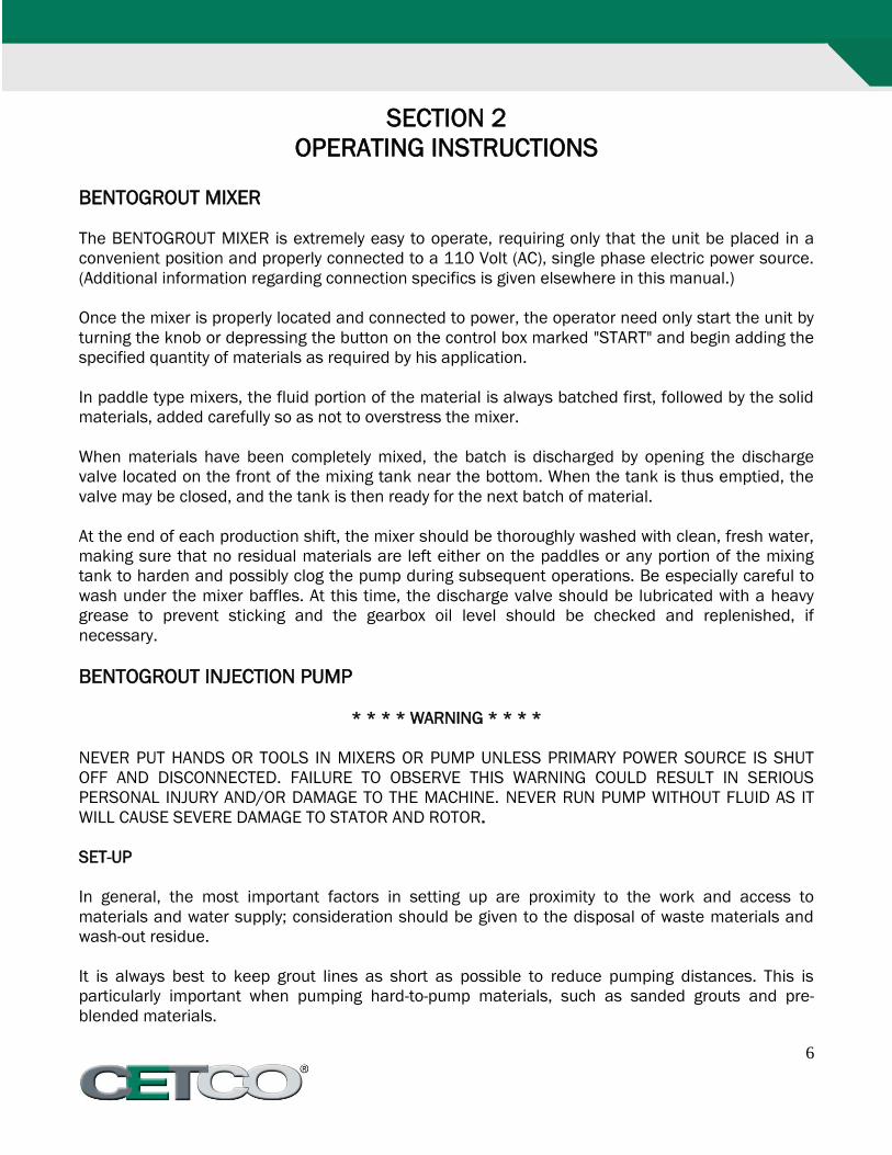
3. Add Bentogrout into mixer. The bag can be pre-opened and then poured in, or this can be
done by using the points on top of the mixer safety grate. Drop a whole bag oriented so that
the length of the bag goes across the forks, this cuts the bag open. Wiggle the ends of the
bag to widen the holes and allow for grout to pour into the mixer, and continue until the
contents of the bag are completely within the mixer.
Utilizing the forks on the covering grate to open Bentogrout bag.
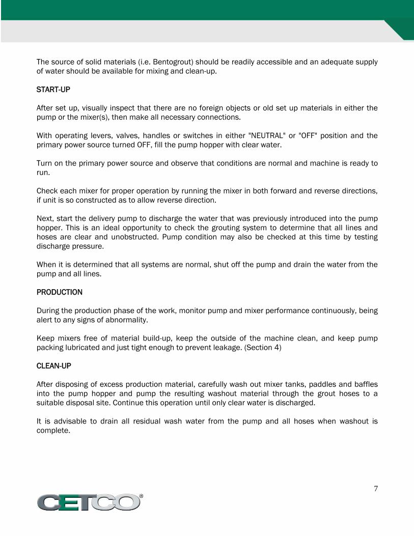
4. Allow to mix continuously for approximately 8 minutes for mixture to achieve a creamy
appearance for pumping. See Figures below.
Left: Chunky, undesirable consistency for pumping. Right: Creamy consistency desirable for Bentogrout Injection
Pumping.
9
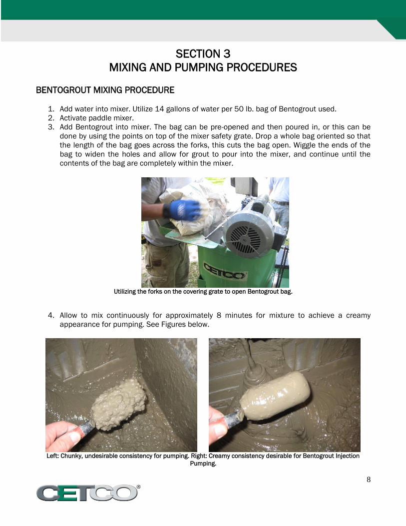
BENTOGROUT INJECTION PUMP PROCEDURES
Exploded view of Bentogrout Injection Pump
10
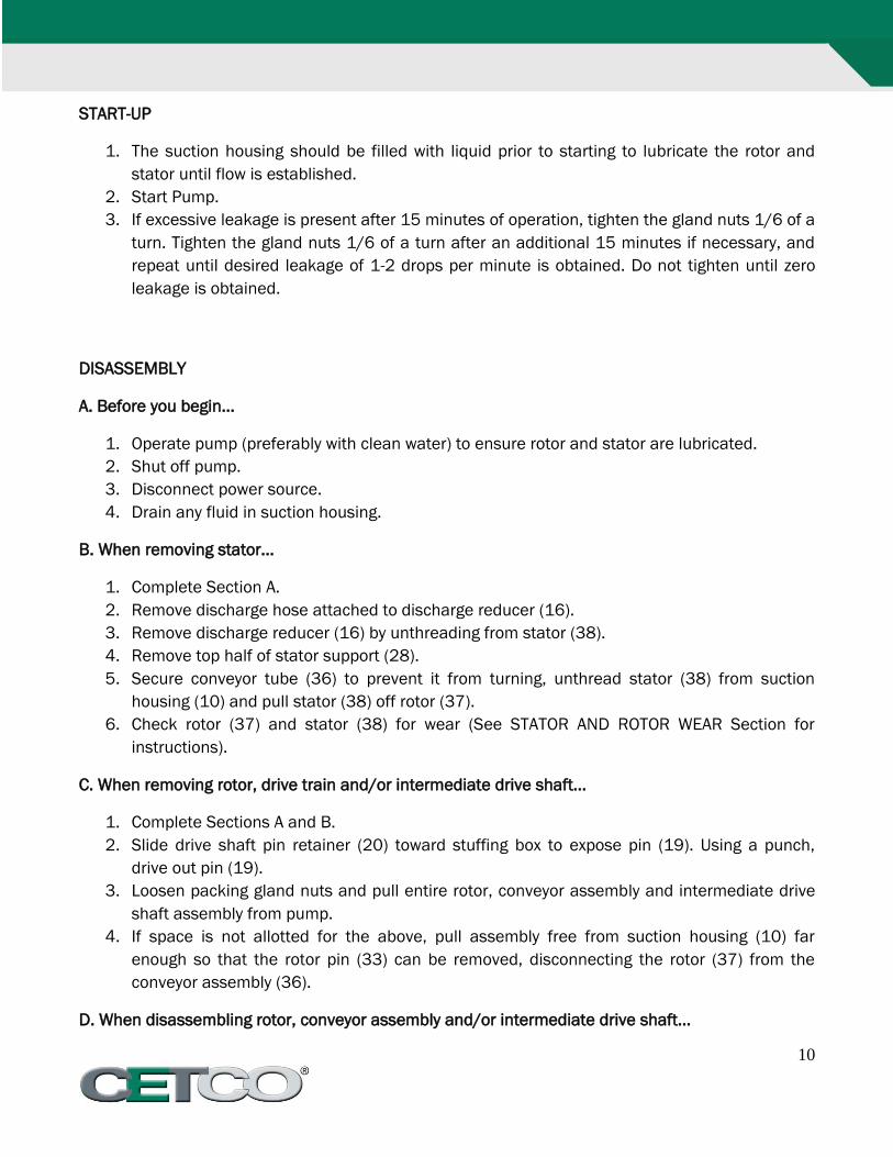
START-UP
1. The suction housing should be filled with liquid prior to starting to lubricate the rotor and
stator until flow is established.
2. Start Pump.
3. If excessive leakage is present after 15 minutes of operation, tighten the gland nuts 1/6 of a
turn. Tighten the gland nuts 1/6 of a turn after an additional 15 minutes if necessary, and
repeat until desired leakage of 1-2 drops per minute is obtained. Do not tighten until zero
leakage is obtained.
DISASSEMBLY
A. Before you begin...
1. Operate pump (preferably with clean water) to ensure rotor and stator are lubricated.
2. Shut off pump.
3. Disconnect power source.
4. Drain any fluid in suction housing.
B. When removing stator...
1. Complete Section A.
2. Remove discharge hose attached to discharge reducer (16).
3. Remove discharge reducer (16) by unthreading from stator (38).
4. Remove top half of stator support (28).
5. Secure conveyor tube (36) to prevent it from turning, unthread stator (38) from suction
housing (10) and pull stator (38) off rotor (37).
6. Check rotor (37) and stator (38) for wear (See STATOR AND ROTOR WEAR Section for
instructions).
C. When removing rotor, drive train and/or intermediate drive shaft...
1. Complete Sections A and B.
2. Slide drive shaft pin retainer (20) toward stuffing box to expose pin (19). Using a punch,
drive out pin (19).
3. Loosen packing gland nuts and pull entire rotor, conveyor assembly and intermediate drive
shaft assembly from pump.
4. If space is not allotted for the above, pull assembly free from suction housing (10) far
enough so that the rotor pin (33) can be removed, disconnecting the rotor (37) from the
conveyor assembly (36).
D. When disassembling rotor, conveyor assembly and/or intermediate drive shaft...
11
1. Complete Section A, B and C.
2. Slide pin retainers (23) toward the conveyor assembly (36) to expose rotor pins (33). Using a
punch, drive out pins (33), and separate rotor, intermediate drive shaft and conveyor
assembly.
3. Remove "O" ring (22) from intermediate drive shaft (32) and one connecting rod washer (24)
from each end of conveyor assembly.
4. Slide pin retainers (25) from each end of conveyor assembly. Using a punch, drive out
connecting rod pins (35) and remove connecting rod ends (34) from conveyor tube (36).
E. When removing packing....
1. Stop pump.
2. Complete Section A.
3. Remove gland adjustment nuts and packing gland (29) from stuffing box.
4. Remove packing rings (30). This is best done by using flexible packing extractors. Use two
extractors simultaneously on opposite sides of each ring. Pull evenly.
5. Remove lantern rings (21) in similar fashion. Twist split ring to remove from shaft. Remove
remaining packing.
ASSEMBLY
The pump is reassembled in reverse order of dismantling. The following suggestions are offered:
Note: While pump is dismantled, check all gaskets, "O" rings and packing. Replace all worn items.
Connecting rod washers (24) should be replaced each time conveyor assembly is disconnected
from the rotor or intermediate drive shaft.
A. Packing assembly...
1. Insert packing rings (30) and lantern ring halves (21) into stuffing box and around the drive
shaft (18), using quantities and positioning as shown in packing diagram for your specific
size pump.
2. Insure that the packing rings are installed with splits staggered at 90 degree intervals and
that the flat side of the lantern ring halves face the packing.
3. All but the last packing ring may fit into the stuffing box. As the pump operates, the packing
will compress and the last ring can be added.
B. Assembly of rotor (37), conveyor tube (36) and/or intermediate drive shaft...
1. Insert connecting rod ends (34) into ends of conveyor tube (36), aligning retaining pin holes
and inserting lightly lubricated pins (35).
1. Note: Two sets of holes are provided in ends of the conveyor tube (36). Should one set of
holes become elongated by wear, rotate the rod ends (34) to align with the unused holes.
12
2. Slide pin retainers (25) into place on each end of the conveyor tube (36).
3. Seat on connecting rod washers (24) on each end of the conveyor assembly.
4. Slip pin retainer (23) over end of conveyor assembly and insert that end of the conveyor
assembly into intermediate shaft (32). Align pin holes and install lightly lubricated pin (33).
Slide pin retainer (23) into place on intermediate shaft to secure the connecting pin.
5. If space is available to install all rotating parts as one unit, install the rotor (37) on the
opposite end of conveyor assembly in the same manner as the intermediate shaft.
C. Installation of intermediate drive shaft (32), conveyor assembly (36), and rotor (37)...
1. Lightly lubricate "O" ring (22) and seat on the intermediate drive shaft (32), next to the
shoulder that will butt against end of drive shaft (18).
2. Space permitting, the complete rotating assembly can be installed as a unit, inserting the
intermediate drive shaft end, through the suction housing (10) and seating in the drive shaft
(18). Proceed to step 4, below.
3. Limited space that will not allow step 2, above, requires that the assembled intermediate
drive shaft (18) and conveyor assembly (36) be partially inserted in the suction housing (10)
and then install the rotor (37) to the conveyor assembly as instructed in Section B, above.
Extreme limited space installations, may require that the stator be installed on the rotor
before installing rotor on the conveyor assembly.
4. Align holes through drive shaft (18) and intermediate drive shaft (32). Install pin (19) and
slide pin retainer (20) over pin holes.
D. Installation of stator (38)...
1. Coat rotor (37) and interior of stator (38) with a generous amount of waterless hand cleaner,
baby oil or other lubricant compatible with rubber. Grease or motor oil is not recommended.
2. Thread stator (38) onto rotor (37) and into suction housing (10).
3. Install top half of stator support (28).
4. Thread discharge reducer (16) on end of stator. Install all discharge hoses removed at
disassembly.
13
SECTION 4
BENTOGROUT INJECTION PUMP MAINTENANCE
The pump has been designed for a minimum of maintenance, the extent of which is routine
lubrication of the bearings. The pump is one of the easiest to work on in that the main elements are
very accessible and require few tools to disassemble.
PACKING
The packing is lubricated through a grease fitting in the stuffing box. Packing gland adjusting nuts
should be evenly adjusted so they are little more than finger tight. Over-tightening of the packing
gland may result in premature packing failure and possible damage to the shaft and gland. When
the packing is new, frequent minor adjustments are recommended for the first few hours of
operation in order to compress and seat the packing. Greasing the packing often but with limited
quantities of grease is the best practice. This can be done through a grease fitting which leads to a
lantern ring in the mid-section of the packing. Do not use a one-piece spiral wrap of packing.
ROTOR WEAR
The rotor should be replaced if:
The rotor pin hole is excessively worn.
The rotor surface is cracked, pitted, deeply grooved (1/32" or more), corroded or if the finish
has been worn off.
STATOR WEAR
If the stator is worn and in need of replacement, its surface may be worn. Test wear by noting how
easily the rotor can be removed. If the rotor slips out too easily the stator should be replace.
RECOMMENDED SPARE PARTS
The pump has been designed and built with all wearable parts replaceable. A recommended inventory of
spare parts is dependent upon the application and importance of continued operation.
For the shortest possible downtime, we recommend the following parts to be stocked:
1 - Rotor
1 - Stator
The above is only a suggested list. For further assistance in determining what you'll need for your application
contact your local CETCO representative.
14
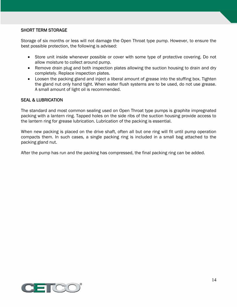
SHORT TERM STORAGE
Storage of six months or less will not damage the Open Throat type pump. However, to ensure the
best possible protection, the following is advised:
Store unit inside whenever possible or cover with some type of protective covering. Do not
allow moisture to collect around pump.
Remove drain plug and both inspection plates allowing the suction housing to drain and dry
completely. Replace inspection plates.
Loosen the packing gland and inject a liberal amount of grease into the stuffing box. Tighten
the gland nut only hand tight. When water flush systems are to be used, do not use grease.
A small amount of light oil is recommended.
SEAL & LUBRICATION
The standard and most common sealing used on Open Throat type pumps is graphite impregnated
packing with a lantern ring. Tapped holes on the side ribs of the suction housing provide access to
the lantern ring for grease lubrication. Lubrication of the packing is essential.
When new packing is placed on the drive shaft, often all but one ring will fit until pump operation
compacts them. In such cases, a single packing ring is included in a small bag attached to the
packing gland nut.
After the pump has run and the packing has compressed, the final packing ring can be added.
15
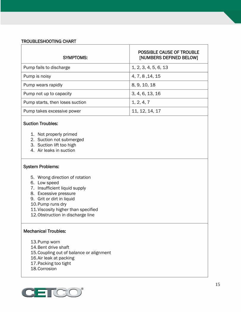
TROUBLESHOOTING CHART
SYMPTOMS:
POSSIBLE CAUSE OF TROUBLE
[NUMBERS DEFINED BELOW]
Pump fails to discharge 1, 2, 3, 4, 5, 6, 13
Pump is noisy 4, 7, 8 ,14, 15
Pump wears rapidly 8, 9, 10, 18
Pump not up to capacity 3, 4, 6, 13, 16
Pump starts, then loses suction 1, 2, 4, 7
Pump takes excessive power 11, 12, 14, 17
Suction Troubles:
1. Not properly primed
2. Suction not submerged
3. Suction lift too high
4. Air leaks in suction
System Problems:
5. Wrong direction of rotation
6. Low speed
7. Insufficient liquid supply
8. Excessive pressure
9. Grit or dirt in liquid
10. Pump runs dry
11. Viscosity higher than specified
12. Obstruction in discharge line
Mechanical Troubles:
13. Pump worn
14. Bent drive shaft
15. Coupling out of balance or alignment
16. Air leak at packing
17. Packing too tight
18. Corrosion
16
SECTION 5
SPECIAL INSTRUCTIONS
SPECIAL INSTRUCTIONS FOR ELECTRICALLY POWERED EQUIPMENT
Some models of CETCO equipment are electrically powered, either direct drive through belts and
sheaves or gearboxes, or electric primary power with hydraulic final drives; in either case, all of the
normal precautions when using any electrically powered equipment apply.
The purpose of this instruction is to alert the user to some of the more common problems that can
occur when using this type of equipment; it is not intended, and is not to be construed as a
complete document regarding electrical safety. It is recommended that all electrical connections
and installations be accomplished by a qualified electrician with knowledge of local electrical
codes.
All CETCO electrical equipment is factory wired with integral grounding conductors; these must be
intact and operational to insure safe operation.
SETUP CHECK LIST
1. Check power source to insure compatibility with the equipment. Domestic equipment may
be 110 volts AC single phase, 230 volts AC single phase, 230 volts AC three phase or 460
volts AC, three phase. Export models will be constructed to comply with destination power
source.
2. Be sure that grounding conductors are attached to a proper external ground source. For
added safety when the machine is being used outdoors, a ground rod may be driven with a
conductor to the machine frame.
3. After setup, always check motors for proper rotation. Reverse rotation of hydraulically driven
equipment can damage hydraulic pumps. If no hydraulic pressure appears immediately after
starting the drive motor, shut the unit down and reverse rotation by appropriate means.
OPERATION
1. Although totally enclosed motors are installed on the equipment, care should be exercised
to avoid splashing electrical components with water or grout materials.
2. If overload relays disengage frequently, check for proper voltage to the motor; long extension
cords will cause voltage drop which results in a motor overload. In some cases, pumping
difficult materials over long distances will also produce an overload condition.