Embed Size (px)
Citation preview
microSYST Systemelectronic GmbH, Am Gewerbepark 11, 92670 Windischeschenbach
+49 9681 91960-0, +49 9681 91960-10, [email protected], www.microsyst.de
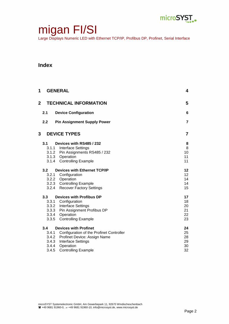
migan FI/SI Large Displays Numeric LED with Ethernet TCP/IP / Profibus DP / Profinet / Serial Interface
Manual
migan FI/SI Large Displays Numeric LED with Ethernet TCP/IP, Profibus DP, Profinet, Serial Interface
microSYST Systemelectronic GmbH, Am Gewerbepark 11, 92670 Windischeschenbach
+49 9681 91960-0, +49 9681 91960-10, [email protected], www.microsyst.de
Page 2
Index
1 GENERAL 4
2 TECHNICAL INFORMATION 5
2.1 Device Configuration 6
2.2 Pin Assignment Supply Power 7
3 DEVICE TYPES 7
3.1 Devices with RS485 / 232 8 3.1.1 Interface Settings 8 3.1.2 Pin Assignments RS485 / 232 10 3.1.3 Operation 11 3.1.4 Controlling Example 11
3.2 Devices with Ethernet TCP/IP 12 3.2.1 Configuration 12 3.2.2 Operation 14 3.2.3 Controlling Example 14 3.2.4 Recover Factory Settings 15
3.3 Devices with Profibus DP 17 3.3.1 Configuration 18 3.3.2 Interface Settings 20 3.3.3 Pin Assignment Profibus DP 21 3.3.4 Operation 22 3.3.5 Controlling Example 23
3.4 Devices with Profinet 24 3.4.1 Configuration of the Profinet Controller 25 3.4.2 Profinet Device: Assign Name 28 3.4.3 Interface Settings 29 3.4.4 Operation 30 3.4.5 Controlling Example 32
migan FI/SI Large Displays Numeric LED with Ethernet TCP/IP, Profibus DP, Profinet, Serial Interface
microSYST Systemelectronic GmbH, Am Gewerbepark 11, 92670 Windischeschenbach
+49 9681 91960-0, +49 9681 91960-10, [email protected], www.microsyst.de
Page 3
4 CONTROL DATA 33
4.1 Display Output 33
4.2 Response Frame 36
5 APPENDIX 37
5.1 Displayable Characters 37
5.2 Protocol “Classic” (Previous Version) 38
5.3 Maintenance and Care 42
5.4 Declaration of Conformity 43
5.5 Warranty / Liability 44
5.6 Versions Overview 45
migan FI/SI Large Displays Numeric LED with Ethernet TCP/IP, Profibus DP, Profinet, Serial Interface
microSYST Systemelectronic GmbH, Am Gewerbepark 11, 92670 Windischeschenbach
+49 9681 91960-0, +49 9681 91960-10, [email protected], www.microsyst.de
Page 4
1 General
The product series “migan FI/SI“ is available with the following optionally interfaces:
Ethernet TCP/IP
Profibus DP
Profinet
Serial (RS232 / RS485) This 7 segment displays are designed for professional use. Depending on the type of device they are suitable for indoor or outdoor use. The modular design allows for cost-effective models of various interfaces with different character heights and numbers of digits.
Change of the Controlling Protocol!
The displays use a new controlling protocol.
Due to the advanced possibilities, we recommend the use of this new option.
By default, the displays are already set to this new universal protocol.
For compatibility reasons, however, the “old” controlling can be activated by
a switch.
For details, refer to chapter “Protocol Classic”.

migan FI/SI Large Displays Numeric LED with Ethernet TCP/IP, Profibus DP, Profinet, Serial Interface
microSYST Systemelectronic GmbH, Am Gewerbepark 11, 92670 Windischeschenbach
+49 9681 91960-0, +49 9681 91960-10, [email protected], www.microsyst.de
Page 5
2 Technical Information
Display type: 7 segment LED Character heights: Indoor use: 60 / 100 / 150 / 200 / 250 mm Character heights: Outdoor use: 100 / 200 / 300 mm Number of digits: 1...40 Number of lines: Standard 1 line, multiple lines on request Display colour: Standard red, other colours on request Operating voltage: 230 VAC / 50 Hz, 110 VAC / 60 Hz or 24 VDC ±20% View: Single sided to four sided Interface: On request:
Ethernet TCP/IP, Profibus DP, Profinet, RS232, RS485 Displayable characters: See corresponding chapter Labelling: On request Housing: Industrial version, powder coated aluminum Housing colour: RAL 7016 (anthracite) Mounting: Articulated arm, angle bracket, hanging on chain or
mounting frame Protection: See chapter „Device Configuration“ Operating temp.: See chapter „Device Configuration“ Storage temp.: -25 ... +70 °C
Details to the used interface can be found in the corresponding chapters.
migan FI/SI Large Displays Numeric LED with Ethernet TCP/IP, Profibus DP, Profinet, Serial Interface
microSYST Systemelectronic GmbH, Am Gewerbepark 11, 92670 Windischeschenbach
+49 9681 91960-0, +49 9681 91960-10, [email protected], www.microsyst.de
Page 6
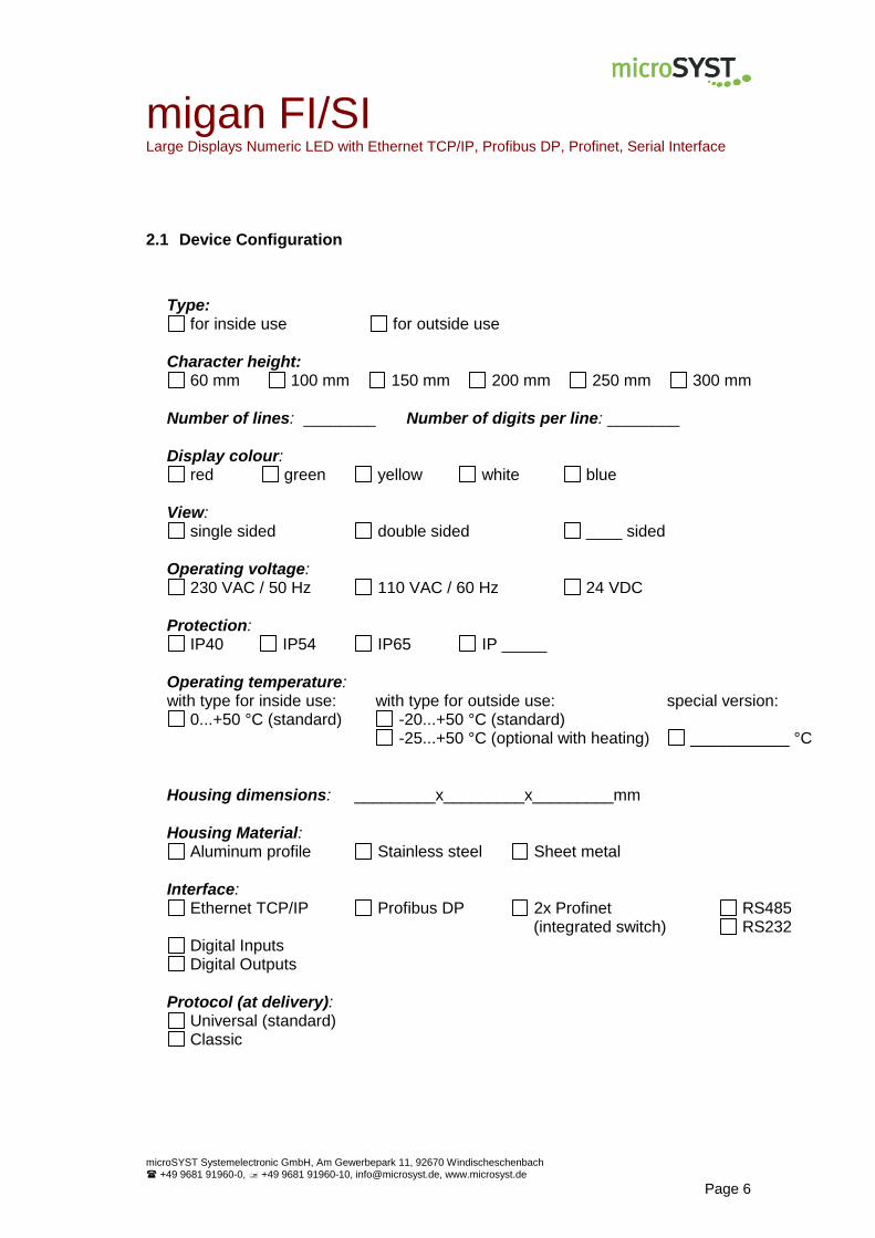
2.1 Device Configuration
Type: for inside use for outside use
Character height: 60 mm 100 mm 150 mm 200 mm 250 mm 300 mm
Number of lines: ________ Number of digits per line: ________
Display colour: red green yellow white blue
View: single sided double sided ____ sided
Operating voltage: 230 VAC / 50 Hz 110 VAC / 60 Hz 24 VDC
Protection: IP40 IP54 IP65 IP _____
Operating temperature: with type for inside use: with type for outside use: special version:
0...+50 °C (standard) -20...+50 °C (standard) -25...+50 °C (optional with heating) ___________ °C
Housing dimensions: _________x_________x_________mm
Housing Material: Aluminum profile Stainless steel Sheet metal
Interface: Ethernet TCP/IP Profibus DP 2x Profinet RS485
(integrated switch) RS232 Digital Inputs Digital Outputs
Protocol (at delivery): Universal (standard) Classic
migan FI/SI Large Displays Numeric LED with Ethernet TCP/IP, Profibus DP, Profinet, Serial Interface
microSYST Systemelectronic GmbH, Am Gewerbepark 11, 92670 Windischeschenbach
+49 9681 91960-0, +49 9681 91960-10, [email protected], www.microsyst.de
Page 7
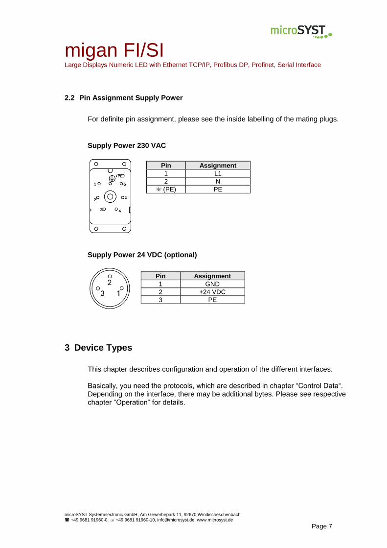
2.2 Pin Assignment Supply Power
For definite pin assignment, please see the inside labelling of the mating plugs.
Supply Power 230 VAC
Supply Power 24 VDC (optional)
3 Device Types
This chapter describes configuration and operation of the different interfaces. Basically, you need the protocols, which are described in chapter “Control Data“. Depending on the interface, there may be additional bytes. Please see respective chapter “Operation“ for details.
Pin Assignment
1 L1
2 N
(PE) PE
Pin Assignment
1 GND
2 +24 VDC
3 PE
migan SI Large Display Numeric LED with Serial Interface
microSYST Systemelectronic GmbH, Am Gewerbepark 11, 92670 Windischeschenbach
+49 9681 91960-0, +49 9681 91960-10, [email protected], www.microsyst.de
Page 8
3.1 Devices with RS485 / 232
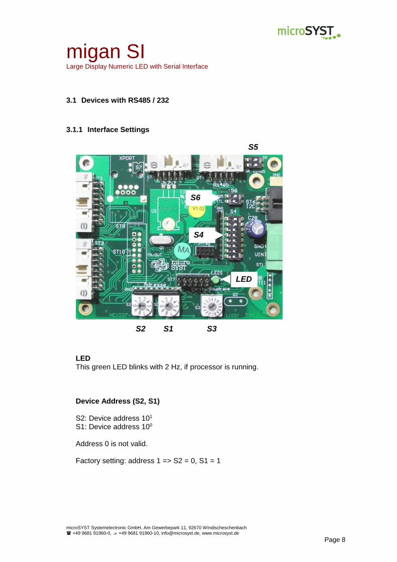
3.1.1 Interface Settings
LED This green LED blinks with 2 Hz, if processor is running.
Device Address (S2, S1) S2: Device address 101 S1: Device address 100
Address 0 is not valid. Factory setting: address 1 => S2 = 0, S1 = 1
S2 S1 S3
S4
S5
S6
LED
migan SI Large Display Numeric LED with Serial Interface
microSYST Systemelectronic GmbH, Am Gewerbepark 11, 92670 Windischeschenbach
+49 9681 91960-0, +49 9681 91960-10, [email protected], www.microsyst.de
Page 9
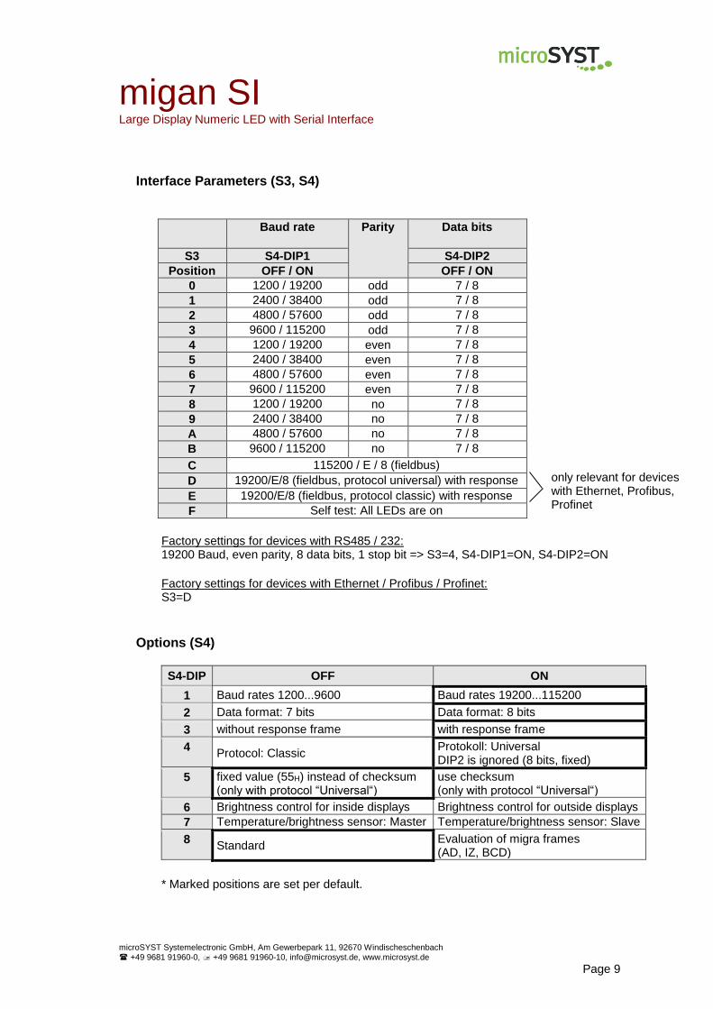
Interface Parameters (S3, S4)
Baud rate
Parity Data bits
S3 S4-DIP1 S4-DIP2
Position OFF / ON OFF / ON
0 1200 / 19200 odd 7 / 8
1 2400 / 38400 odd 7 / 8
2 4800 / 57600 odd 7 / 8
3 9600 / 115200 odd 7 / 8
4 1200 / 19200 even 7 / 8
5 2400 / 38400 even 7 / 8
6 4800 / 57600 even 7 / 8
7 9600 / 115200 even 7 / 8
8 1200 / 19200 no 7 / 8
9 2400 / 38400 no 7 / 8
A 4800 / 57600 no 7 / 8
B 9600 / 115200 no 7 / 8
C 115200 / E / 8 (fieldbus)
D 19200/E/8 (fieldbus, protocol universal) with response
E 19200/E/8 (fieldbus, protocol classic) with response
F Self test: All LEDs are on
Factory settings for devices with RS485 / 232: 19200 Baud, even parity, 8 data bits, 1 stop bit => S3=4, S4-DIP1=ON, S4-DIP2=ON
Factory settings for devices with Ethernet / Profibus / Profinet: S3=D
Options (S4)
S4-DIP OFF ON
1 Baud rates 1200...9600 Baud rates 19200...115200
2 Data format: 7 bits Data format: 8 bits
3 without response frame with response frame
4 Protocol: Classic
Protokoll: Universal DIP2 is ignored (8 bits, fixed)
5 fixed value (55H) instead of checksum (only with protocol “Universal“)
use checksum (only with protocol “Universal“)
6 Brightness control for inside displays Brightness control for outside displays
7 Temperature/brightness sensor: Master Temperature/brightness sensor: Slave
8 Standard
Evaluation of migra frames (AD, IZ, BCD)
* Marked positions are set per default.
only relevant for devices with Ethernet, Profibus, Profinet
migan SI Large Display Numeric LED with Serial Interface
microSYST Systemelectronic GmbH, Am Gewerbepark 11, 92670 Windischeschenbach
+49 9681 91960-0, +49 9681 91960-10, [email protected], www.microsyst.de
Page 10
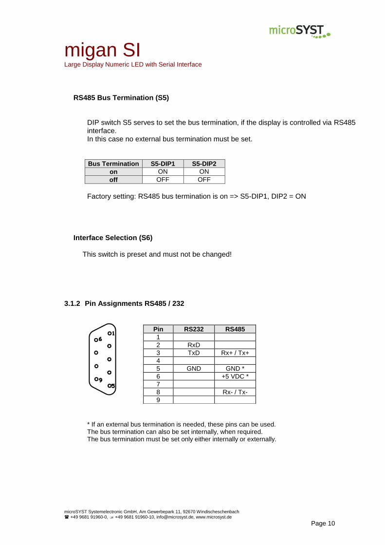
RS485 Bus Termination (S5) DIP switch S5 serves to set the bus termination, if the display is controlled via RS485 interface. In this case no external bus termination must be set. Bus Termination S5-DIP1 S5-DIP2
on ON ON
off OFF OFF
Factory setting: RS485 bus termination is on => S5-DIP1, DIP2 = ON
Interface Selection (S6) This switch is preset and must not be changed!
3.1.2 Pin Assignments RS485 / 232
* If an external bus termination is needed, these pins can be used. The bus termination can also be set internally, when required. The bus termination must be set only either internally or externally.
Pin RS232 RS485
1
2 RxD
3 TxD Rx+ / Tx+
4
5 GND GND *
6 +5 VDC *
7
8 Rx- / Tx-
9

migan SI Large Display Numeric LED with Serial Interface
microSYST Systemelectronic GmbH, Am Gewerbepark 11, 92670 Windischeschenbach
+49 9681 91960-0, +49 9681 91960-10, [email protected], www.microsyst.de
Page 11
3.1.3 Operation
Start-Up Procedure:
Segment test
<first 2 digits of the baud rate > <parity> <data bits>
A<device address>
After this, the display waits for valid user data. If a valid frame is sent during the test routine, the test is aborted and data are displayed. The controlling of the device happens with the protocols, that are described in chapter “Control Data“.
3.1.4 Controlling Example
For details see chapter “Control Data”. The use of the protocol “universal” is required (standard, see chapter “General”). Demands:
Display with 3 digits and device address 1
Show “1.23”
Data type: unsigned CHAR
Fixed checksum (standard)
Response frame is activated per DIP switch (standard)
1. Send frame to the display
01 06 00 30 80 00 7B 55
\/ \/ \_________/ \/ \/
| | | | |
| LEN O1…O4 “123”|
| |
ADR CHK
2. Wait for response frame
01 02 00 55
migan EN Large Display Numeric LED with Ethernet TCP/IP Interface
microSYST Systemelectronic GmbH, Am Gewerbepark 11, 92670 Windischeschenbach
+49 9681 91960-0, +49 9681 91960-10, [email protected], www.microsyst.de
Page 12
3.2 Devices with Ethernet TCP/IP
3.2.1 Configuration
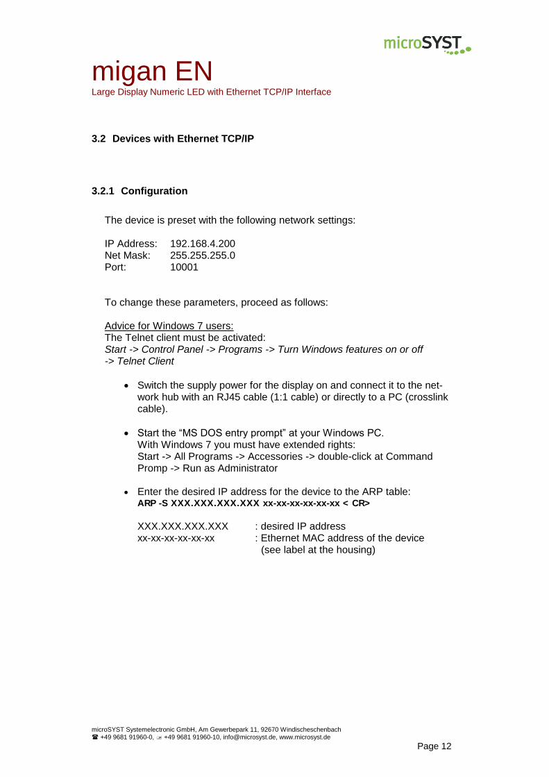
The device is preset with the following network settings: IP Address: 192.168.4.200 Net Mask: 255.255.255.0 Port: 10001
To change these parameters, proceed as follows: Advice for Windows 7 users: The Telnet client must be activated: Start -> Control Panel -> Programs -> Turn Windows features on or off -> Telnet Client
Switch the supply power for the display on and connect it to the net-work hub with an RJ45 cable (1:1 cable) or directly to a PC (crosslink cable).
Start the “MS DOS entry prompt” at your Windows PC. With Windows 7 you must have extended rights: Start -> All Programs -> Accessories -> double-click at Command Promp -> Run as Administrator
Enter the desired IP address for the device to the ARP table: ARP -S XXX.XXX.XXX.XXX xx-xx-xx-xx-xx-xx < CR>
XXX.XXX.XXX.XXX : desired IP address xx-xx-xx-xx-xx-xx : Ethernet MAC address of the device
(see label at the housing)

migan EN Large Display Numeric LED with Ethernet TCP/IP Interface
microSYST Systemelectronic GmbH, Am Gewerbepark 11, 92670 Windischeschenbach
+49 9681 91960-0, +49 9681 91960-10, [email protected], www.microsyst.de
Page 13
Establish a Telnet connection to port 1: TELNET XXX.XXX.XXX.XXX 1 < CR>
This connection will fail (disconnect within 3 seconds). However, the IP address is temporarily changed. Close the Telnet window after acknowledging the error message.
Establish a Telnet connection to port 9999: TELNET XXX.XXX.XXX.XXX 9999 < CR> After the connection has been established, immediately press the en-ter key (within 5 seconds) in order to enter the setup mode.
Enter “0” (Server).
Enter the desired IP address and press the enter key.
Repeatedly press the enter key until ”Netmask: Number of Bits for Host Part (…)“ appears. Enter here the number of free bits for the IP address, f.e. “8“ for the netmask 255.255.255.0 (=11111111.11111111.11111111.00000000) or “11“ for the netmask 255.255.248.0 (=11111111.11111111.11111000.00000000) and press the enter key.
Repeatedly press the enter key until “Your choice?” appears.
Press “9” to save all settings (-> the Telnet connection is interrupted). Configuration of the Ethernet interface is now complete. Now, the control frame can be transmitted to the display via the selected IP address (TCP/IP connection via port 10001).

migan EN Large Display Numeric LED with Ethernet TCP/IP Interface
microSYST Systemelectronic GmbH, Am Gewerbepark 11, 92670 Windischeschenbach
+49 9681 91960-0, +49 9681 91960-10, [email protected], www.microsyst.de
Page 14
3.2.2 Operation
After start-up, a segment test is performed. Subsequently, after establishing a TCP/IP connection with adjusted IP address and port 10001, the device waits for valid user data. The controlling of the device happens with the protocols, which are described in chapter “Control Data“.
3.2.3 Controlling Example
For details see chapter “Control Data”. The use of the protocol “universal” is required (standard, see chapter “General”). Demands:
Display with 3 digits
Show “1.23”
Data type: unsigned CHAR
1. Send frame to the display
01 06 00 30 80 00 7B 55
\/ \/ \_________/ \/ \/
| | | | |
| LEN O1…O4 “123”|
| |
ADR CHK
2. Wait for response frame
01 02 00 55
migan EN Large Display Numeric LED with Ethernet TCP/IP Interface
microSYST Systemelectronic GmbH, Am Gewerbepark 11, 92670 Windischeschenbach
+49 9681 91960-0, +49 9681 91960-10, [email protected], www.microsyst.de
Page 15
3.2.4 Recover Factory Settings
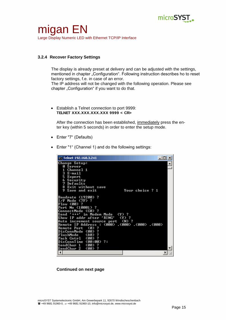
The display is already preset at delivery and can be adjusted with the settings, mentioned in chapter „Configuration“. Following instruction describes ho to reset factory settings, f.e. in case of an error. The IP address will not be changed with the following operation. Please see chapter „Configuration“ if you want to do that.
Establish a Telnet connection to port 9999: TELNET XXX.XXX.XXX.XXX 9999 < CR> After the connection has been established, immediately press the en-ter key (within 5 seconds) in order to enter the setup mode.
Enter "7“ (Defaults)
Enter "1“ (Channel 1) and do the following settings:
Continued on next page
migan EN Large Display Numeric LED with Ethernet TCP/IP Interface
microSYST Systemelectronic GmbH, Am Gewerbepark 11, 92670 Windischeschenbach
+49 9681 91960-0, +49 9681 91960-10, [email protected], www.microsyst.de
Page 16
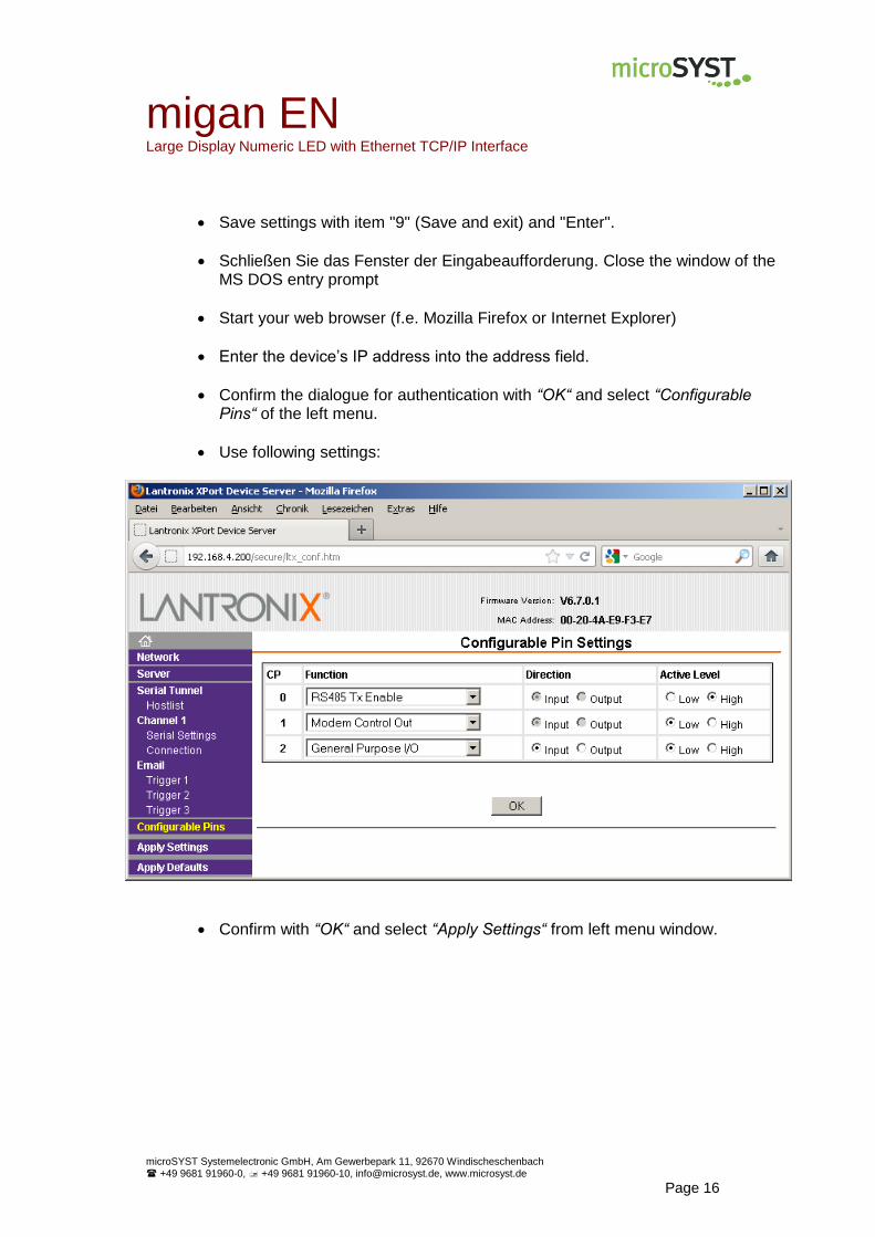
Save settings with item "9" (Save and exit) and "Enter".
Schließen Sie das Fenster der Eingabeaufforderung. Close the window of the MS DOS entry prompt
Start your web browser (f.e. Mozilla Firefox or Internet Explorer)
Enter the device’s IP address into the address field.
Confirm the dialogue for authentication with “OK“ and select “Configurable Pins“ of the left menu.
Use following settings:
Confirm with “OK“ and select “Apply Settings“ from left menu window.
migan PB Large Display Numeric LED with Profibus DP Interface
microSYST Systemelectronic GmbH, Am Gewerbepark 11, 92670 Windischeschenbach
+49 9681 91960-0, +49 9681 91960-10, [email protected], www.microsyst.de
Page 17
3.3 Devices with Profibus DP
Interface Data
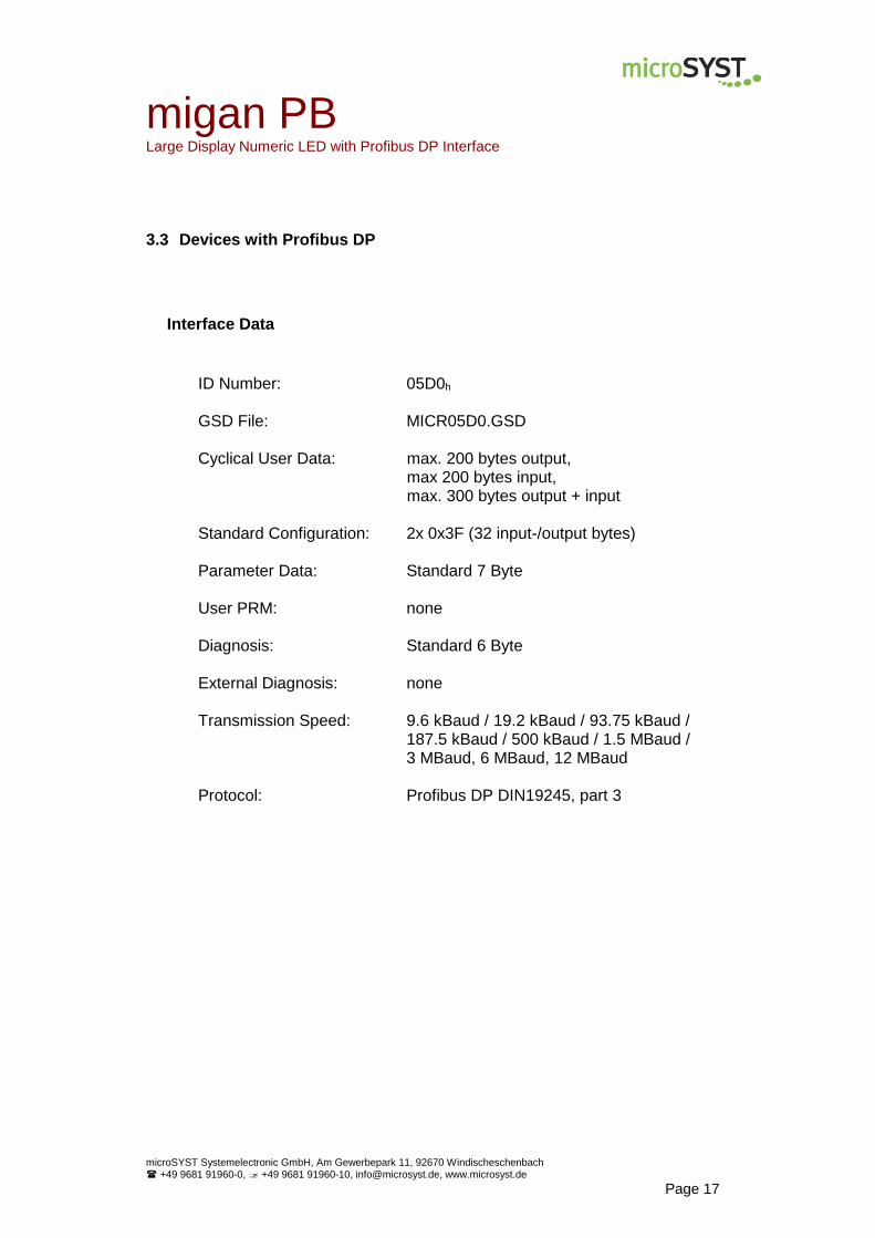
ID Number: 05D0h GSD File: MICR05D0.GSD Cyclical User Data: max. 200 bytes output, max 200 bytes input, max. 300 bytes output + input Standard Configuration: 2x 0x3F (32 input-/output bytes) Parameter Data: Standard 7 Byte User PRM: none Diagnosis: Standard 6 Byte External Diagnosis: none Transmission Speed: 9.6 kBaud / 19.2 kBaud / 93.75 kBaud / 187.5 kBaud / 500 kBaud / 1.5 MBaud / 3 MBaud, 6 MBaud, 12 MBaud Protocol: Profibus DP DIN19245, part 3

migan PB Large Display Numeric LED with Profibus DP Interface
microSYST Systemelectronic GmbH, Am Gewerbepark 11, 92670 Windischeschenbach
+49 9681 91960-0, +49 9681 91960-10, [email protected], www.microsyst.de
Page 18
3.3.1 Configuration
The configuration of the Profibus interface normally happens using the GSD file. It is initially imported into the "Device Catalog" of the configu-ration software. Subsequently, the Profibus interface can be “dragged” into the bus system and then be configured. With the configuration, the user can individually adapt data width within the data transfer. Data widths of 1 to 16 bytes maximum are possible. By specifying these identifiers in any order, the desired total data width is set for both the input and the output data.
Data Identifier Number of Bytes Function / Description
0x10 1 Input data
0x11 2 Input data
: : :
0x1F 16 Input data
0x20 1 Output data
0x21 2 Output data
: : :
0x2F 16 Output data
0x30 1/1 Input / output data (1 byte each)
0x31 2/2 Input / output data (2 bytes each)
: :
0x3F 16/16 Input / output data (16 bytes each)
The maximum number of input and output bytes is 200 bytes each. However a total number of 300 bytes (input + output) may not be exceed-ed. Default configuration: 2x 0x3F = 32 input and 32 output bytes Attention: The configured output data width must be at least 2 bytes larger than the longest protocol to be sent (because of toggle and length byte). The configured input data width must be at least 2 bytes larger than the longest used response frame (because of toggle and length byte).

migan PB Large Display Numeric LED with Profibus DP Interface
microSYST Systemelectronic GmbH, Am Gewerbepark 11, 92670 Windischeschenbach
+49 9681 91960-0, +49 9681 91960-10, [email protected], www.microsyst.de
Page 19
DP Diagnosis Data
The device does not support any extended diagnosis data. Default diag-nosis is utilised.
DP Parameter Data
The User_Prm_Data are not utilised by the interface. However, a test is run to determine whether or not User_Prm_Data are transferred by the Profi-bus master. If User_Prm_Data are transferred, Profibus initialisation is dis-abled and the slave must be reconfigured and parameterised.
Note: Standard parametrisation is required and is normally installed by the uti-lised DP configurators.
migan PB Large Display Numeric LED with Profibus DP Interface
microSYST Systemelectronic GmbH, Am Gewerbepark 11, 92670 Windischeschenbach
+49 9681 91960-0, +49 9681 91960-10, [email protected], www.microsyst.de
Page 20
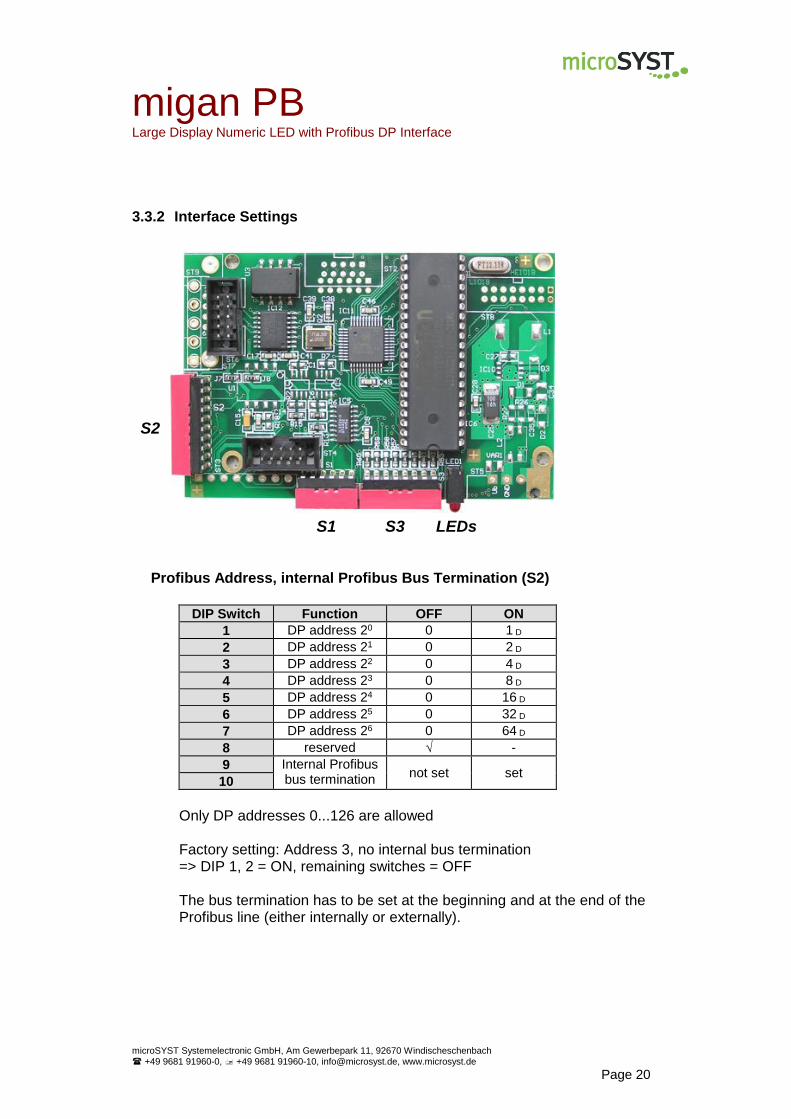
3.3.2 Interface Settings
Profibus Address, internal Profibus Bus Termination (S2)
DIP Switch Function OFF ON
1 DP address 20 0 1 D
2 DP address 21 0 2 D
3 DP address 22 0 4 D
4 DP address 23 0 8 D
5 DP address 24 0 16 D
6 DP address 25 0 32 D
7 DP address 26 0 64 D
8 reserved √ -
9 Internal Profibus bus termination
not set set 10
Only DP addresses 0...126 are allowed Factory setting: Address 3, no internal bus termination => DIP 1, 2 = ON, remaining switches = OFF The bus termination has to be set at the beginning and at the end of the Profibus line (either internally or externally).
S2
S1 S3 LEDs

migan PB Large Display Numeric LED with Profibus DP Interface
microSYST Systemelectronic GmbH, Am Gewerbepark 11, 92670 Windischeschenbach
+49 9681 91960-0, +49 9681 91960-10, [email protected], www.microsyst.de
Page 21
LEDs
LED Status Meaning
red ON
no Profibus DP connection or RAM error (if green LED OFF)
OFF Profibus DP connection established
green
OFF Controller is not running (hardware error)
ON Controller is running
temporary OF (blinking) UART communication (frame has been sent or received)
Default Settings S1, S3 The DIP switches are preset and must not be changed!
DIP Switch DIP 1 DIP 2 DIP 3 DIP 4 DIP 5 DIP 6 DIP 7 DIP 8
S1 OFF ON ON ON ON ON - -
S3 OFF OFF ON ON OFF OFF OFF ON
3.3.3 Pin Assignment Profibus DP
Pin Assignment
1
2
3 Rx+ / Tx+ (B strand)
4 RTS
5 GND, electrically isolated
6 5V, electrically isolated
7
8 Rx- / Tx- (A strand)
9
migan PB Large Display Numeric LED with Profibus DP Interface
microSYST Systemelectronic GmbH, Am Gewerbepark 11, 92670 Windischeschenbach
+49 9681 91960-0, +49 9681 91960-10, [email protected], www.microsyst.de
Page 22
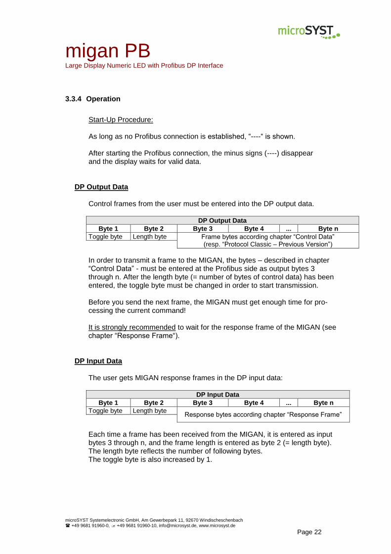
3.3.4 Operation
Start-Up Procedure: As long as no Profibus connection is established, “----“ is shown. After starting the Profibus connection, the minus signs (----) disappear and the display waits for valid data.
DP Output Data Control frames from the user must be entered into the DP output data.
DP Output Data
Byte 1 Byte 2 Byte 3 Byte 4 ... Byte n
Toggle byte Length byte Frame bytes according chapter “Control Data” (resp. “Protocol Classic – Previous Version”)
In order to transmit a frame to the MIGAN, the bytes – described in chapter “Control Data” - must be entered at the Profibus side as output bytes 3 through n. After the length byte (= number of bytes of control data) has been entered, the toggle byte must be changed in order to start transmission. Before you send the next frame, the MIGAN must get enough time for pro-cessing the current command! It is strongly recommended to wait for the response frame of the MIGAN (see chapter “Response Frame“).
DP Input Data The user gets MIGAN response frames in the DP input data:
DP Input Data
Byte 1 Byte 2 Byte 3 Byte 4 ... Byte n
Toggle byte Length byte Response bytes according chapter “Response Frame”
Each time a frame has been received from the MIGAN, it is entered as input bytes 3 through n, and the frame length is entered as byte 2 (= length byte). The length byte reflects the number of following bytes. The toggle byte is also increased by 1.
migan PB Large Display Numeric LED with Profibus DP Interface
microSYST Systemelectronic GmbH, Am Gewerbepark 11, 92670 Windischeschenbach
+49 9681 91960-0, +49 9681 91960-10, [email protected], www.microsyst.de
Page 23
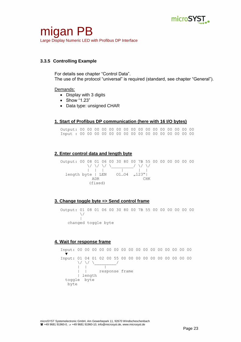
3.3.5 Controlling Example
For details see chapter “Control Data”. The use of the protocol “universal” is required (standard, see chapter “General”). Demands:
Display with 3 digits
Show “1.23”
Data type: unsigned CHAR
1. Start of Profibus DP communication (here with 16 I/O bytes)
Output: 00 00 00 00 00 00 00 00 00 00 00 00 00 00 00 00
Input : 00 00 00 00 00 00 00 00 00 00 00 00 00 00 00 00
2. Enter control data and length byte
Output: 00 08 01 06 00 30 80 00 7B 55 00 00 00 00 00 00
\/ \/ \/ \_________/ \/ \/
| | | | | |
length byte | LEN O1…O4 „123“|
ADR CHK
(fixed)
3. Change toggle byte => Send control frame
Output: 01 08 01 06 00 30 80 00 7B 55 00 00 00 00 00 00
\/
|
changed toggle byte
4. Wait for response frame
Input: 00 00 00 00 00 00 00 00 00 00 00 00 00 00 00 00
▼
Input: 01 04 01 02 00 55 00 00 00 00 00 00 00 00 00 00
\/ \/ \_________/
| | |
| | response frame
| length
toggle byte
byte

migan PN Large Display Numeric LED with Profinet Interface
microSYST Systemelectronic GmbH, Am Gewerbepark 11, 92670 Windischeschenbach
+49 9681 91960-0, +49 9681 91960-10, [email protected], www.microsyst.de
Page 24
3.4 Devices with Profinet
Interface Data
Interface: 2 x Profinet IO (with integrated switch) Baud rate: 100 Mbit/s Standards: IEC 61158 / 61784 Profinet IO device RT (conformance class B) Profinet IO device IRT (conformance class C) Features: - Base: Siemens ERTEC200 - Real-time classes 1, 2 and 3 - RTA, LLDP, SNMP, MIB-II, LLDP-MIB - MRP (media redundancy) - DCP - Fast Startup - Send clock = 0.25, 0.5, 1, 2, 4 ms - Clock divider = 1…512 (RT), 1…16 (IRT) - Output data width = 0…250 bytes - Input data width = 0…250 bytes - Vendor-/Device-ID = 01CFh / 0001h
migan PN Large Display Numeric LED with Profinet Interface
microSYST Systemelectronic GmbH, Am Gewerbepark 11, 92670 Windischeschenbach
+49 9681 91960-0, +49 9681 91960-10, [email protected], www.microsyst.de
Page 25
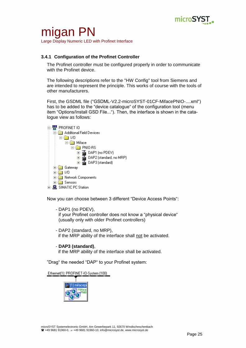
3.4.1 Configuration of the Profinet Controller
The Profinet controller must be configured properly in order to communicate with the Profinet device. The following descriptions refer to the "HW Config" tool from Siemens and are intended to represent the principle. This works of course with the tools of other manufacturers. First, the GSDML file (“GSDML-V2.2-microSYST-01CF-MifacePNIO-....xml“) has to be added to the “device catalogue“ of the configuration tool (menu item “Options/Install GSD File...“). Then, the interface is shown in the cata-logue view as follows:
Now you can choose between 3 different “Device Access Points“:
- DAP1 (no PDEV), if your Profinet controller does not know a “physical device“ (usually only with older Profinet controllers)
- DAP2 (standard, no MRP), if the MRP ability of the interface shall not be activated.
- DAP3 (standard), if the MRP ability of the interface shall be activated.
”Drag“ the needed “DAP“ to your Profinet system:
migan PN Large Display Numeric LED with Profinet Interface
microSYST Systemelectronic GmbH, Am Gewerbepark 11, 92670 Windischeschenbach
+49 9681 91960-0, +49 9681 91960-10, [email protected], www.microsyst.de
Page 26
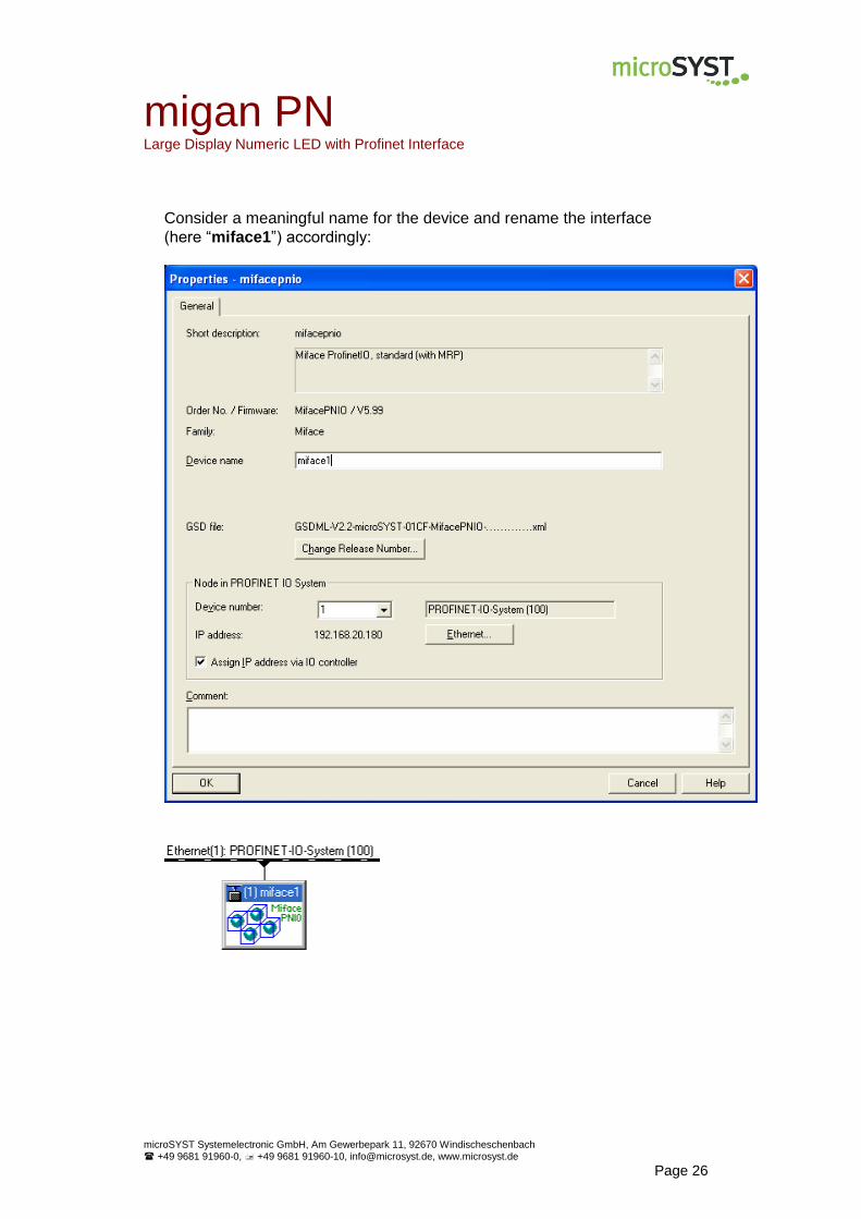
Consider a meaningful name for the device and rename the interface
(here “miface1”) accordingly:
migan PN Large Display Numeric LED with Profinet Interface
microSYST Systemelectronic GmbH, Am Gewerbepark 11, 92670 Windischeschenbach
+49 9681 91960-0, +49 9681 91960-10, [email protected], www.microsyst.de
Page 27
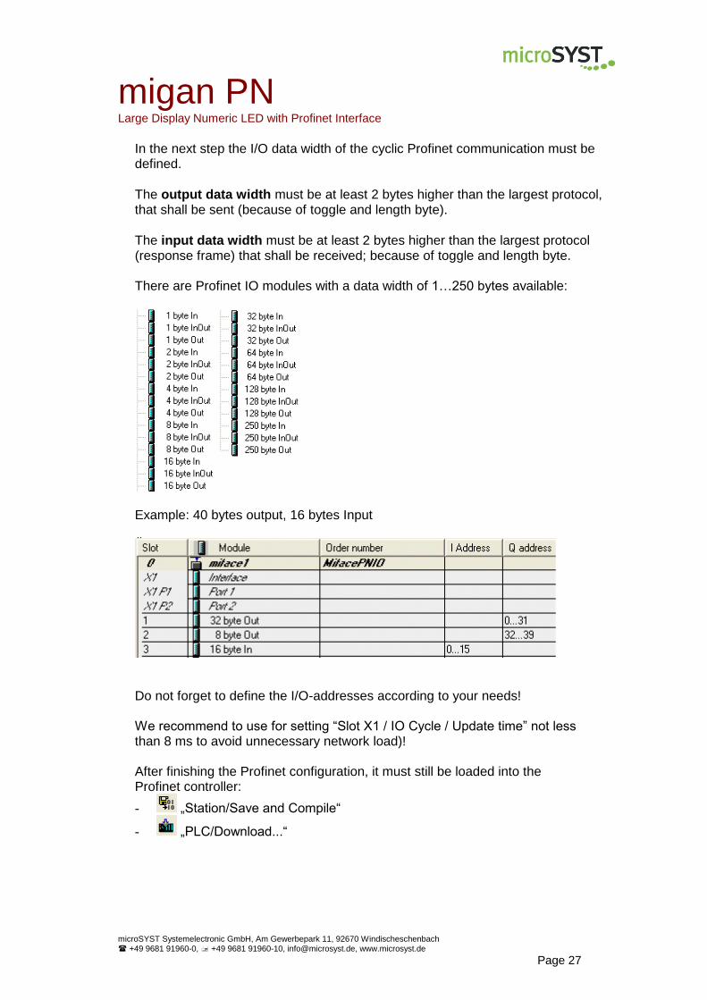
In the next step the I/O data width of the cyclic Profinet communication must be defined.
The output data width must be at least 2 bytes higher than the largest protocol, that shall be sent (because of toggle and length byte).
The input data width must be at least 2 bytes higher than the largest protocol (response frame) that shall be received; because of toggle and length byte. There are Profinet IO modules with a data width of 1…250 bytes available:
Example: 40 bytes output, 16 bytes Input
Do not forget to define the I/O-addresses according to your needs! We recommend to use for setting “Slot X1 / IO Cycle / Update time” not less than 8 ms to avoid unnecessary network load)! After finishing the Profinet configuration, it must still be loaded into the Profinet controller:
- „Station/Save and Compile“
- „PLC/Download...“
migan PN Large Display Numeric LED with Profinet Interface
microSYST Systemelectronic GmbH, Am Gewerbepark 11, 92670 Windischeschenbach
+49 9681 91960-0, +49 9681 91960-10, [email protected], www.microsyst.de
Page 28
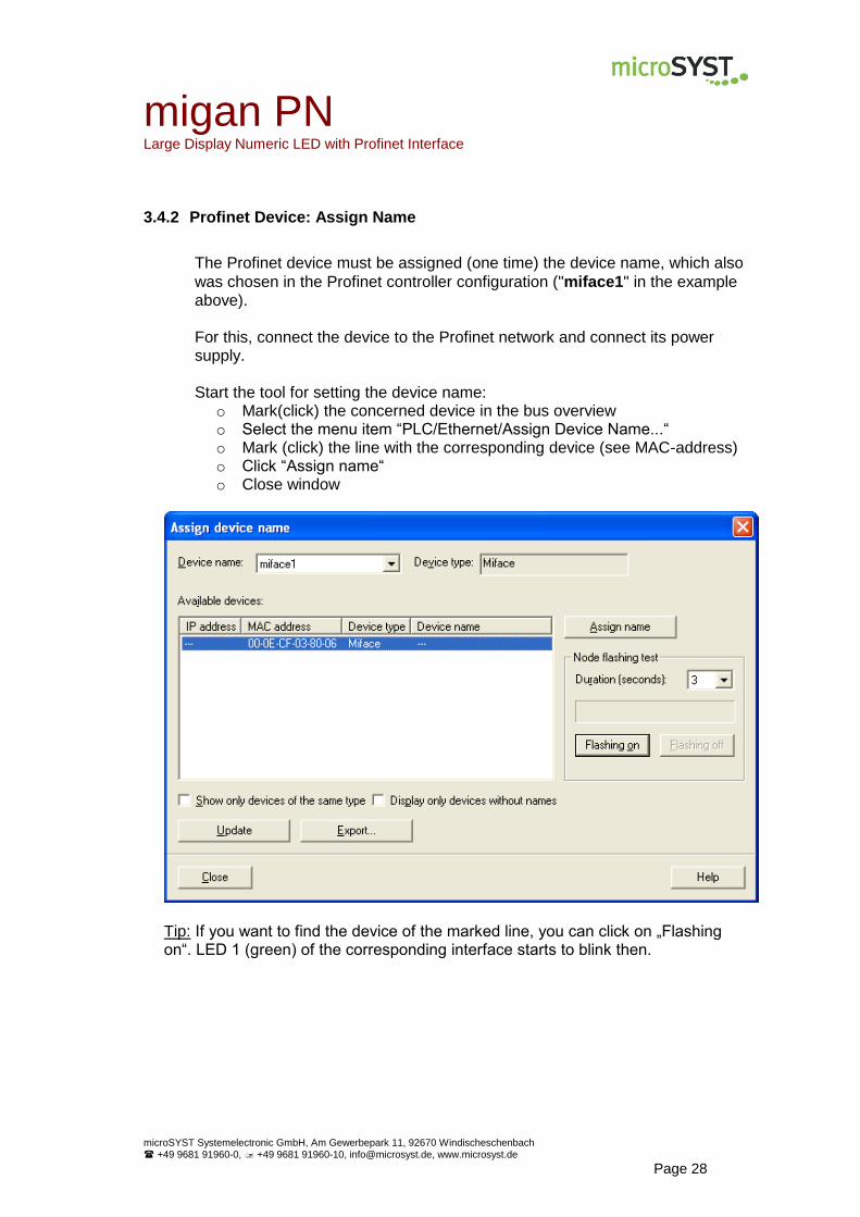
3.4.2 Profinet Device: Assign Name
The Profinet device must be assigned (one time) the device name, which also
was chosen in the Profinet controller configuration ("miface1" in the example above). For this, connect the device to the Profinet network and connect its power supply. Start the tool for setting the device name:
o Mark(click) the concerned device in the bus overview o Select the menu item “PLC/Ethernet/Assign Device Name...“ o Mark (click) the line with the corresponding device (see MAC-address) o Click “Assign name“ o Close window
Tip: If you want to find the device of the marked line, you can click on „Flashing on“. LED 1 (green) of the corresponding interface starts to blink then.
migan PN Large Display Numeric LED with Profinet Interface
microSYST Systemelectronic GmbH, Am Gewerbepark 11, 92670 Windischeschenbach
+49 9681 91960-0, +49 9681 91960-10, [email protected], www.microsyst.de
Page 29
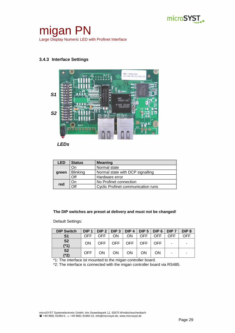
3.4.3 Interface Settings
LED Status Meaning
green
On Normal state
Blinking Normal state with DCP signalling
Off Hardware error
red On No Profinet connection
Off Cyclic Profinet communication runs
The DIP switches are preset at delivery and must not be changed!
Default Settings:
DIP Switch DIP 1 DIP 2 DIP 3 DIP 4 DIP 5 DIP 6 DIP 7 DIP 8
S1 OFF OFF ON ON OFF OFF OFF OFF
S2
(*1) ON OFF OFF OFF OFF OFF - -
S2
(*2) OFF ON ON ON ON ON - -
*1: The interface ist mounted to the migan controller board. *2: The interface is connected with the migan controller board via RS485.
S1
S2
LEDs
migan PN Large Display Numeric LED with Profinet Interface
microSYST Systemelectronic GmbH, Am Gewerbepark 11, 92670 Windischeschenbach
+49 9681 91960-0, +49 9681 91960-10, [email protected], www.microsyst.de
Page 30
3.4.4 Operation
Start-Up: The connection between the Profinet controller and the Profinet device is established automatically (this can last up to 10 seconds). The red LED of the interface goes out, as soon as the Profinet connection is established. To let this happen, the PN controller must be correctly configured and the PN device must have the matching name. The communication between Profinet controller and the display (Profinet device) happens within cyclic data traffic.

migan PN Large Display Numeric LED with Profinet Interface
microSYST Systemelectronic GmbH, Am Gewerbepark 11, 92670 Windischeschenbach
+49 9681 91960-0, +49 9681 91960-10, [email protected], www.microsyst.de
Page 31
Profinet Output Data The user must enter control frames into the Profinet output data.
Profinet Output Data
Byte 1 Byte 2 Byte 3 Byte 4 ... Byte n
Toggle byte Length byte Frame bytes according chapter “Control Data” (resp. “Protocol Classic – Previous Version”)
In order to transmit a frame to the MIGAN, the frame bytes – described in chapter “Control Data” - must be entered at the Profinet side as output bytes 3 through n. After the length byte (= number of bytes of control data) has been entered, the toggle byte must be changed in order to start transmission. Before you send the next frame, the MIGAN must get enough time for pro-cessing the current command! It is strongly recommended to wait for the response frame of the MIGAN (see chapter „Response Frame“).
Profinet Input Data
Profinet Input Data
Byte 1 Byte 2 Byte 3 Byte 4 ... Byte n
Toggle byte Length byte Response bytes according chapter “Response Frame”
Each time a frame has been received from the MIGAN, it is entered as input bytes 3 through n, and the frame length is entered as byte 2 (= length byte). The value of the length byte corresponds with the number of bytes of the re-sponse frame. The toggle byte is also increased by 1. Thus only the toggle byte needs to be monitored at the Profinet con-troller side. As soon as it changes, data of the received frame can be read out and next frame can be sent.
migan PN Large Display Numeric LED with Profinet Interface
microSYST Systemelectronic GmbH, Am Gewerbepark 11, 92670 Windischeschenbach
+49 9681 91960-0, +49 9681 91960-10, [email protected], www.microsyst.de
Page 32
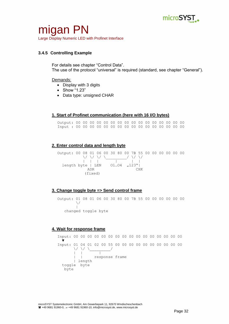
3.4.5 Controlling Example
For details see chapter “Control Data”. The use of the protocol “universal” is required (standard, see chapter “General”). Demands:
Display with 3 digits
Show “1.23”
Data type: unsigned CHAR
1. Start of Profinet communication (here with 16 I/O bytes)
Output: 00 00 00 00 00 00 00 00 00 00 00 00 00 00 00 00
Input : 00 00 00 00 00 00 00 00 00 00 00 00 00 00 00 00
2. Enter control data and length byte
Output: 00 08 01 06 00 30 80 00 7B 55 00 00 00 00 00 00
\/ \/ \/ \_________/ \/ \/
| | | | | |
length byte | LEN O1…O4 „123“|
ADR CHK
(fixed)
3. Change toggle byte => Send control frame
Output: 01 08 01 06 00 30 80 00 7B 55 00 00 00 00 00 00
\/
|
changed toggle byte
4. Wait for response frame
Input: 00 00 00 00 00 00 00 00 00 00 00 00 00 00 00 00
▼
Input: 01 04 01 02 00 55 00 00 00 00 00 00 00 00 00 00
\/ \/ \_________/
| | |
| | response frame
| length
toggle byte
byte
migan FI/SI Large Displays Numeric LED with Ethernet TCP/IP / Profibus DP / Profinet / Serial Interface
microSYST Systemelectronic GmbH, Am Gewerbepark 11, 92670 Windischeschenbach
+49 9681 91960-0, +49 9681 91960-10, [email protected], www.microsyst.de
Page 33
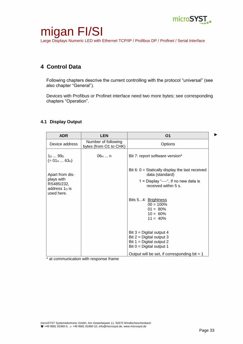
4 Control Data
Following chapters descrive the current controlling with the protocol “universal” (see also chapter “General”). Devices with Profibus or Profinet interface need two more bytes; see corresponding chapters “Operation”.
4.1 Display Output
ADR LEN O1 ►
Device address Number of following
bytes (from O1 to CHK) Options
1D ... 99D (= 01H ... 63H) Apart from dis-plays with RS485/232, address 1D is used here.
06H ... n
Bit 7: report software version* Bit 6: 0 = Statically display the last received data (standard)
1 = Display “----“, if no new data is received within 5 s. Bits 5...4: Brightness 00 = 100% 01 = 80% 10 = 60% 11 = 40% Bit 3 = Digital output 4 Bit 2 = Digital output 3 Bit 1 = Digital output 2 Bit 0 = Digital output 1
Output will be set, if corresponding bit = 1
* at communication with response frame
migan FI/SI Large Displays Numeric LED with Ethernet TCP/IP / Profibus DP / Profinet / Serial Interface
microSYST Systemelectronic GmbH, Am Gewerbepark 11, 92670 Windischeschenbach
+49 9681 91960-0, +49 9681 91960-10, [email protected], www.microsyst.de
Page 34
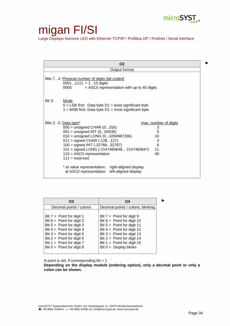
O2 ►
Output format
Bits 7...4: Physical number of digits (bit coded) 0001...1111 = 1...15 digits 0000 = ASCII representation with up to 40 digits Bit 3: Mode 0 = LSB first: Data byte D1 = least significant byte 1 = MSB first: Data byte D1 = most significant byte Bits 2...0: Data type* max. number of digits 000 = unsigned CHAR (0...255) 3 001 = unsigned INT (0...65535) 5
010 = unsigned LONG (0...4294967296) 10 011 = signed CHAR (-128...127) 4 100 = signed INT (-32768...32767) 6 101 = signed LONG (-2147483648... 2147483647) 11 110 = ASCII representation 40 111 = reserved
* at value representation: right-aligned display at ASCII representation: left-aligned display
O3 O4 ►
Decimal points / colons Decimal points / colons, blinking
Bit 7 = Point for digit 1 Bit 6 = Point for digit 2 Bit 5 = Point for digit 3 Bit 4 = Point for digit 4 Bit 3 = Point for digit 5 Bit 2 = Point for digit 6 Bit 1 = Point for digit 7 Bit 0 = Point for digit 8
Bit 7 = Point for digit 9 Bit 6 = Point for digit 10 Bit 5 = Point for digit 11 Bit 4 = Point for digit 12 Bit 3 = Point for digit 13 Bit 2 = Point for digit 14 Bit 1 = Point for digit 15 Bit 0 = Display blinks
A point is set, if corresponding bit = 1
Depending on the display module (ordering option), only a decimal point or only a
colon can be shown.

migan FI/SI Large Displays Numeric LED with Ethernet TCP/IP / Profibus DP / Profinet / Serial Interface
microSYST Systemelectronic GmbH, Am Gewerbepark 11, 92670 Windischeschenbach
+49 9681 91960-0, +49 9681 91960-10, [email protected], www.microsyst.de
Page 35
D1…Dn CHK
Data bytes (value- or ASCII representation) Checksum
Value representation: CHAR value: 1 byte INT value: 2 bytes LONG value: 4 bytes ASCII representation (max. 80 bytes): 1 byte per character, max. 40 digits, Bit 7 = 1: digit blinks The decimal point or colon (ordering option) has character code 2CH or 2EH and is always set at the previous digit.
depending on S4-DIP5:
standard: 55H (fixed value)
or LOW byte of the sum of all previ-
ous bytes (ADR...Dn)
Controlling devices with multiple display areas (e.g. 2 lines): The partition from O2…Dn is used repeatedly according to the number of display areas (see example 3). Please attend to the maximum total frame length of 150 bytes.
Example 1: Display with 4 digits, device address 1, unsigned INT (LSB first), brightness = 60%, display value = 1.23 01 07 20 41 40 00 7B 00 55
Example 2: Display with 4 digits, device address 1, ASCII representation, brightness = 60%, display value = 12.34 01 0A 20 46 00 00 31 32 2E 33 34 55
Example 3: Display with 2 lines and 4 digits per line, device address 1, unsigned INT (LSB first), display value for line 1 = 1.23, display value for line 2 = 5.67 01 0C 00 41 40 00 7B 00 41 40 00 37 02 55
\______________/\______________/
Line 1 Line 2
(O2...D2) (O2...D2)
migan FI/SI Large Displays Numeric LED with Ethernet TCP/IP / Profibus DP / Profinet / Serial Interface
microSYST Systemelectronic GmbH, Am Gewerbepark 11, 92670 Windischeschenbach
+49 9681 91960-0, +49 9681 91960-10, [email protected], www.microsyst.de
Page 36
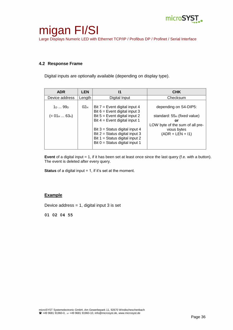
4.2 Response Frame
Digital inputs are optionally available (depending on display type).
ADR LEN I1 CHK
Device address Length Digital Input Checksum
1D ... 99D
(= 01H ... 63H)
02H
Bit 7 = Event digital input 4 Bit 6 = Event digital input 3 Bit 5 = Event digital input 2 Bit 4 = Event digital input 1 Bit 3 = Status digital input 4 Bit 2 = Status digital input 3 Bit 1 = Status digital input 2 Bit 0 = Status digital input 1
depending on S4-DIP5:
standard: 55H (fixed value)
or LOW byte of the sum of all pre-
vious bytes (ADR + LEN + I1)
Event of a digital input = 1, if it has been set at least once since the last query (f.e. with a button). The event is deleted after every query.
Status of a digital input = 1, if it’s set at the moment.
Example
Device address = 1, digital input 3 is set 01 02 04 55
migan FI/SI Large Displays Numeric LED with Ethernet TCP/IP / Profibus DP / Profinet / Serial Interface
microSYST Systemelectronic GmbH, Am Gewerbepark 11, 92670 Windischeschenbach
+49 9681 91960-0, +49 9681 91960-10, [email protected], www.microsyst.de
Page 37
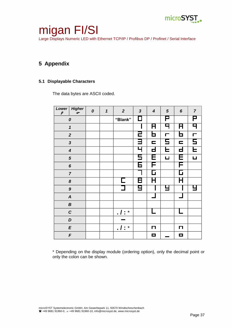
5 Appendix
5.1 Displayable Characters
The data bytes are ASCII coded.
Lower
Higher
0 1 2 3 4 5 6 7
0 “Blank”
1
2
3
4
5
6
7
8
9
A
B
C . / : *
D
E . / : *
F
* Depending on the display module (ordering option), only the decimal point or only the colon can be shown.

migan FI/SI Large Displays Numeric LED with Ethernet TCP/IP / Profibus DP / Profinet / Serial Interface
microSYST Systemelectronic GmbH, Am Gewerbepark 11, 92670 Windischeschenbach
+49 9681 91960-0, +49 9681 91960-10, [email protected], www.microsyst.de
Page 38
5.2 Protocol “Classic” (Previous Version)
Basically, we recommend the current controlling which is described in the chapter “Control Data”. For compatibility reasons with already delivered devices, the previous protocol and inteface properties are still integrated and can be activated by a switch. Devices with Profibus or Profinet interface need two more bytes; see corresponding chapters “Operation”.
Depending on the device interface, following settings are used: Devices with RS232/485: S3 = 7, all switches of S4 = OFF (9600 / E / 7 / 1) Devices with Ethernet / Profibus / Profinet: S3 = E, all switches of S4 = OFF
S4
S3

migan FI/SI Large Displays Numeric LED with Ethernet TCP/IP / Profibus DP / Profinet / Serial Interface
microSYST Systemelectronic GmbH, Am Gewerbepark 11, 92670 Windischeschenbach
+49 9681 91960-0, +49 9681 91960-10, [email protected], www.microsyst.de
Page 39
Display Output
STX ADRH* ADRL* ►
Start of transmission Device address HIGH,
ASCII coded Device address LOW,
ASCII coded
3CH (or 02H) 30H ... 39H 30H ... 39H
P1 P2 P3 ►
Point byte 1 Point byte 2 Point byte 3
Bits 7...5 = 010 Bit 4 = Point for digit 1 Bit 3 = Point for digit 2 Bit 2 = Point for digit 3 Bit 1 = Point for digit 4 Bit 0 = Point for digit 5
Bits 7...5 = 010 Bit 4 = Point for digit 6 Bit 3 = Point for digit 7 Bit 2 = Point for digit 8 Bit 1 = Point for digit 9 Bit 0 = Point for digit 10
Bits 7...5 = 010 Bit 4 = Point for digit 11 Bit 3 = Point for digit 12 Bit 2 = Point for digit 13 Bit 1 = Point for digit 14 Bit 0 = Point for digit 15
To display a point, the corresponding bit must be set.
D1...Dn ETX
Data bytes End of transmission
One byte per character to be displayed; ASCII coded Bit 7 = 1: Digit blinks = 0: Digits is shown statically The decimal point has character code 2CH or 2EH and is set at the former digit each. Writing direction is from the left to the right.
3EH if STX = 3CH (03H if STX = 02H)
*ADRH, ADRL: Those bytes specify HIGH and LOW byte of the adjusted device address. Apart from displays with RS485/232, address 1 is always used here -> ADRH = 30H, ADRL = 31H
Example 1 Device address 23, display “1.23“, decimal point is controlled via the point bytes 3C 32 33 50 40 40 31 32 33 3E
Example 2 Device address 23, display “1.23“, decimal point as ASCII character via the data bytes 3C 32 33 40 40 40 31 2E 32 33 3E
migan FI/SI Large Displays Numeric LED with Ethernet TCP/IP / Profibus DP / Profinet / Serial Interface
microSYST Systemelectronic GmbH, Am Gewerbepark 11, 92670 Windischeschenbach
+49 9681 91960-0, +49 9681 91960-10, [email protected], www.microsyst.de
Page 40
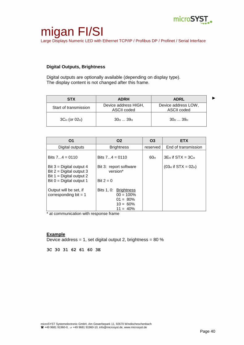
Digital Outputs, Brightness Digital outputs are optionally available (depending on display type). The display content is not changed after this frame.
STX ADRH ADRL ►
Start of transmission Device address HIGH,
ASCII coded Device address LOW,
ASCII coded
3CH (or 02H)
30H ... 39H 30H ... 39H
O1 O2 O3 ETX
Digital outputs Brightness reserved End of transmission
Bits 7...4 = 0110 Bit 3 = Digital output 4 Bit 2 = Digital output 3 Bit 1 = Digital output 2 Bit 0 = Digital output 1 Output will be set, if corresponding bit = 1
Bits 7...4 = 0110 Bit 3: report software version* Bit 2 = 0 Bits 1, 0: Brightness 00 = 100% 01 = 80% 10 = 60% 11 = 40%
60H
3EH if STX = 3CH (03H if STX = 02H)
* at communication with response frame
Example Device address = 1, set digital output 2, brightness = 80 % 3C 30 31 62 61 60 3E
migan FI/SI Large Displays Numeric LED with Ethernet TCP/IP / Profibus DP / Profinet / Serial Interface
microSYST Systemelectronic GmbH, Am Gewerbepark 11, 92670 Windischeschenbach
+49 9681 91960-0, +49 9681 91960-10, [email protected], www.microsyst.de
Page 41
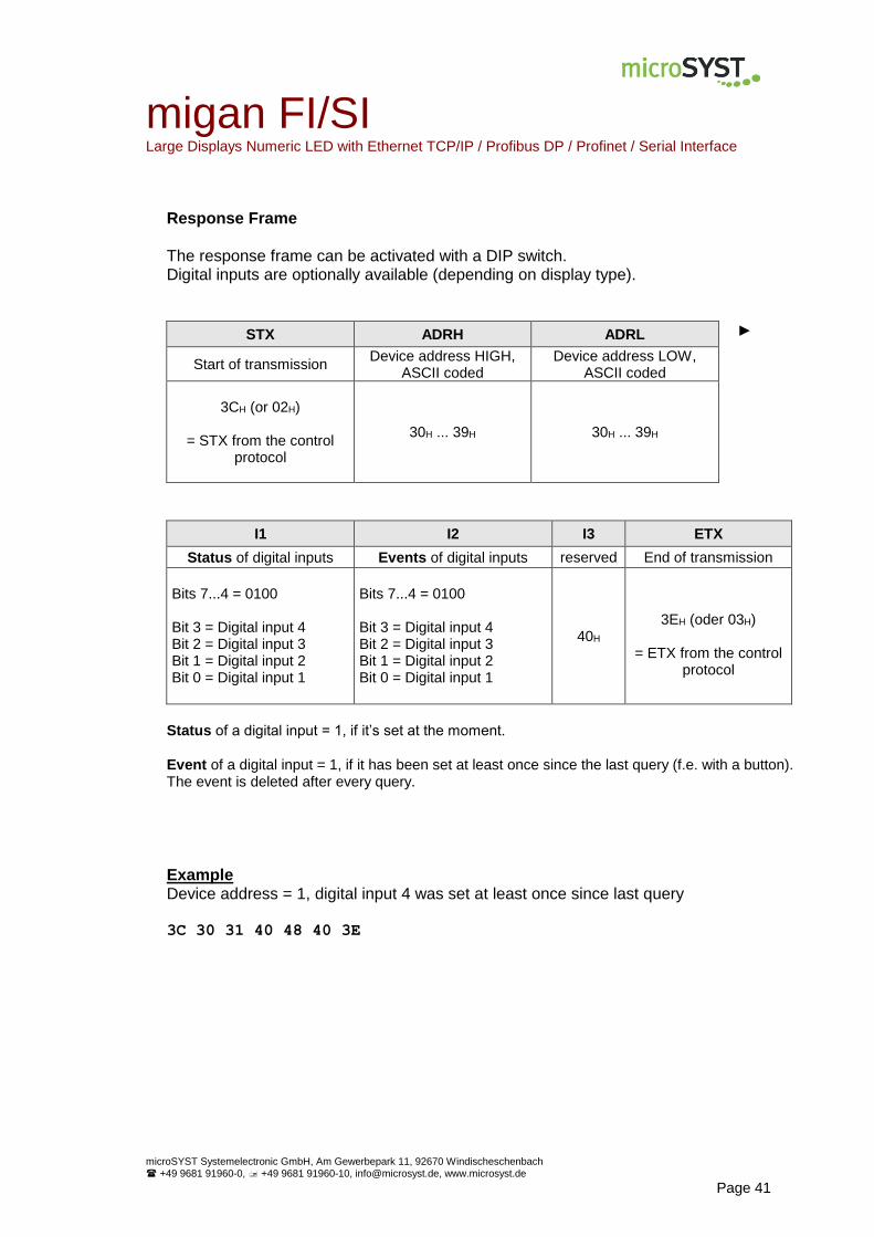
Response Frame
The response frame can be activated with a DIP switch. Digital inputs are optionally available (depending on display type).
STX ADRH ADRL ►
Start of transmission Device address HIGH,
ASCII coded Device address LOW,
ASCII coded
3CH (or 02H)
= STX from the control protocol
30H ... 39H 30H ... 39H
I1 I2 I3 ETX
Status of digital inputs Events of digital inputs reserved End of transmission
Bits 7...4 = 0100 Bit 3 = Digital input 4 Bit 2 = Digital input 3 Bit 1 = Digital input 2 Bit 0 = Digital input 1
Bits 7...4 = 0100 Bit 3 = Digital input 4 Bit 2 = Digital input 3 Bit 1 = Digital input 2 Bit 0 = Digital input 1
40H
3EH (oder 03H)
= ETX from the control
protocol
Status of a digital input = 1, if it’s set at the moment.
Event of a digital input = 1, if it has been set at least once since the last query (f.e. with a button). The event is deleted after every query.
Example Device address = 1, digital input 4 was set at least once since last query 3C 30 31 40 48 40 3E
migan FI/SI Large Displays Numeric LED with Ethernet TCP/IP / Profibus DP / Profinet / Serial Interface
microSYST Systemelectronic GmbH, Am Gewerbepark 11, 92670 Windischeschenbach
+49 9681 91960-0, +49 9681 91960-10, [email protected], www.microsyst.de
Page 42
5.3 Maintenance and Care
Please observe the following instructions:
Make sure that the housing can be opened for adjustment and mainte-nance even after the display has been installed. Allow for adequate clear-ance at the back, front and top of the display unit in order to follow for suffi-cient ventilation (if vent slots are included).
Display quality is impaired by direct illumination with bright light sources and/or direct sunlight.
The display must be switched off before cleaning.
Protect the display from excessive humidity, extreme vibration, direct sun-light and extreme temperatures. Non-observance may lead to malfunction-ing or destruction of the device. Under certain circumstances electrical shock, fire and explosion may occur as well. Information concerning allow-able ambient conditions, including recommended temperature ranges, can be found in the chapter entitled „Technical Data“.
The display may not be placed into service if the device and/or the power cable are known to be damaged.
Do not attempt to repair the device yourself. The guarantee is rendered null and void if the device is tampered with by unauthorized persons.
migan FI/SI Large Displays Numeric LED with Ethernet TCP/IP / Profibus DP / Profinet / Serial Interface
microSYST Systemelectronic GmbH, Am Gewerbepark 11, 92670 Windischeschenbach
+49 9681 91960-0, +49 9681 91960-10, [email protected], www.microsyst.de
Page 43
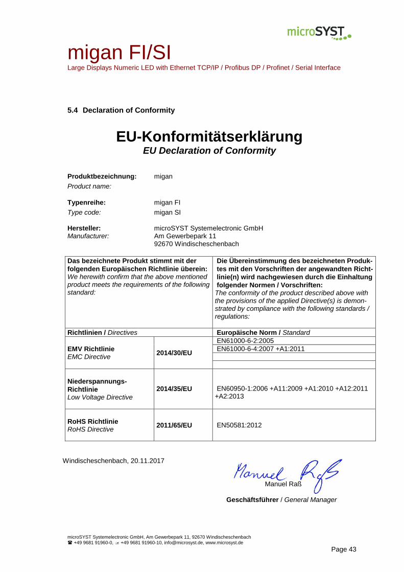
5.4 Declaration of Conformity
EU-Konformitätserklärung EU Declaration of Conformity
Produktbezeichnung: migan
Product name:
Typenreihe: migan FI
Type code: migan SI
Hersteller: microSYST Systemelectronic GmbH Manufacturer: Am Gewerbepark 11 92670 Windischeschenbach
Das bezeichnete Produkt stimmt mit der
folgenden Europäischen Richtlinie überein: We herewith confirm that the above mentioned product meets the requirements of the following standard:
Die Übereinstimmung des bezeichneten Produk-
tes mit den Vorschriften der angewandten Richt-
linie(n) wird nachgewiesen durch die Einhaltung
folgender Normen / Vorschriften: The conformity of the product described above with the provisions of the applied Directive(s) is demon-strated by compliance with the following standards / regulations:
Richtlinien / Directives Europäische Norm / Standard
EMV Richtlinie EMC Directive
2014/30/EU
EN61000-6-2:2005
EN61000-6-4:2007 +A1:2011
Niederspannungs-
Richtlinie Low Voltage Directive
2014/35/EU
EN60950-1:2006 +A11:2009 +A1:2010 +A12:2011 +A2:2013
RoHS Richtlinie RoHS Directive
2011/65/EU EN50581:2012
Windischeschenbach, 20.11.2017 Manuel Raß
Geschäftsführer / General Manager
migan FI/SI Large Displays Numeric LED with Ethernet TCP/IP / Profibus DP / Profinet / Serial Interface
microSYST Systemelectronic GmbH, Am Gewerbepark 11, 92670 Windischeschenbach
+49 9681 91960-0, +49 9681 91960-10, [email protected], www.microsyst.de
Page 44
5.5 Warranty / Liability
For the product, liability is assumed for defects, which existed at the delivery date according to our General Terms and Conditions. Technically changes as well as errors are excepted. A claim for delivery of a new product does not exist. The buyer has to check the received product im-mediately and indicate evident defects at the latest 24 hours after detection. Non-observance of notification requirements is equated with acceptance of the defect. Not immediately visible defects have to be indicated immediately after their perception too. Generally, defects and their symptoms must be described as accurately as possible in order to allow for reproducibility and elimination. The buyer must provide for access to the relevant device and all required and/or useful infor-mation at no charge and must make all of the required data and machine time available free of charge. The guarantee does not cover defects, which result from non-observance of the prescribed conditions of use, or from improper handling. If the device has been placed at the disposal of the buyer for test purposes and has been purchased subsequent to such testing, both parties agree that the product is to be considered “used” and that it has been purchased “as is”. No guarantee claims may be made in such cases. The General Terms and Conditions of microSYST Systemelectronic GmbH in current version apply as well.

migan FI/SI Large Displays Numeric LED with Ethernet TCP/IP / Profibus DP / Profinet / Serial Interface
microSYST Systemelectronic GmbH, Am Gewerbepark 11, 92670 Windischeschenbach
+49 9681 91960-0, +49 9681 91960-10, [email protected], www.microsyst.de
Page 45
5.6 Versions Overview
Version Date Comments
1.00 1.10
1.20 1.30 1.40 1.50 1.60 1.70 1.80 1.90 2.00 2.10 2.20
03.12.12 21.03.13
18.07.13 17.10.13 22.01.14 23.04.14 08.05.14 27.06.14 11.11.14 17.09.15 17.11.1527.04.16 20.11.17
Dokument created Additional display option: “----“, if no new data is received within 5 s (valid from HE1037). Standard: Universal protocol, factory settings of the interfaces Logo migan 2 -> migan Decimal point or colon possible Default settings of the Profinet interface changed Operating voltage Device configuration: View Description of LSB, MSB Info to additional bytes with Profibus and Profinet devices Declaration of conformity Change of address
Certified per DIN EN ISO 9001.