Embed Size (px)
Citation preview
BER performance simulation in a multi user MIMO TAS/MRC Nakagami-m channel using BPSK, QPSK and QAM
Under the Supervision of:
Mrs. Jayatri Bora,
(Asst. Professor, Department of ECE)
Vikas Pandey DE/12/EC/001
Rubina Khongsit DE/12/EC/002
Ruptanu Pal DE/12/EC/008
Tanya Singh DE/12/EC/020
Renji Thomas DE/11/EC/051
Kh. Nongpoknganba DE/11/EC/108
OBJECTIVE
Bit Error Rate Performance Simulation
For Multi user MIMO TAS/MRC Nakagami-m
Channel
Using BPSK, QPSK and QAM
Using Matlab
INSPIRATION
It is the most recent technique being used in
industries
Not much work has been done on Nakagami-
m fading
BPSK, QPSK and QAM are popularly used in
commercial MIMO devices
STEPS INVOLVED
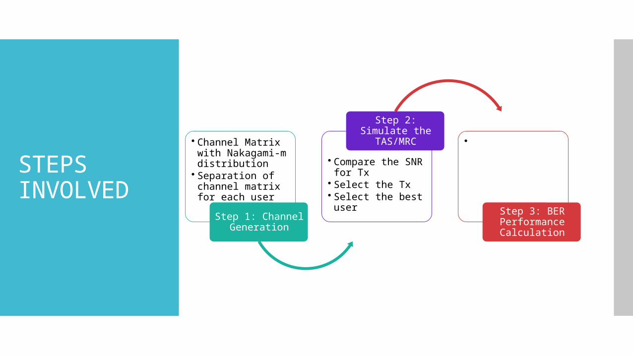
• Channel Matrix with Nakagami-m distribution
• Separation of channel matrix for each user
Step 1: Channel Generation
• Compare the SNR for Tx
• Select the Tx• Select the best user
Step 2: Simulate the TAS/MRC •
Step 3: BER Performance Calculation
KEY TERMS
Mu-MIMO
TAS (Transmit Antenna Selection)
MRC (Maximal Ratio Combining)
Fading
Nakagami-m channel
BER
MIMO
MIMO: Multiple Input Multiple Output
Multiple antennas at both the transmitter and
receiver .
Offers increase in data throughput and link
range.
Spreads the same total transmit power over
the antennas to achieve:
an array gain
a diversity gain
SINGLE USER MIMO
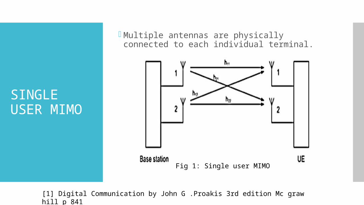
Multiple antennas are physically connected to each individual terminal.
Fig 1: Single user MIMO
[1] Digital Communication by John G .Proakis 3rd edition Mc graw hill p 841
MULTI USER MIMO
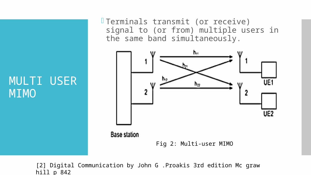
Terminals transmit (or receive) signal to (or from) multiple users in the same band simultaneously.
Fig 2: Multi-user MIMO
[2] Digital Communication by John G .Proakis 3rd edition Mc graw hill p 842
TAS and MRC
TAS: Transmit Antenna Selection
Selects the best transmitting antenna.
Feedback path.
Reduces complexity.
MRC: Maximal-Ratio Combining
An optimal diversity technique with a maximum
SNR criterion.
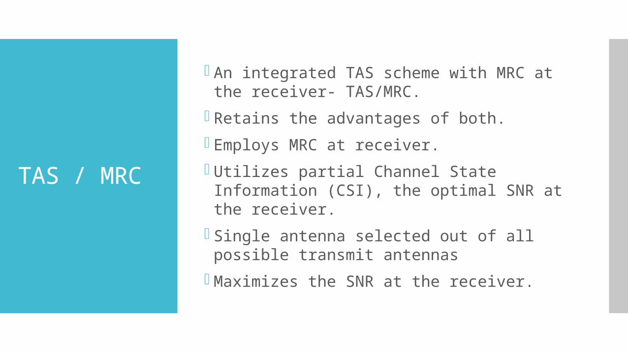
TAS / MRC
An integrated TAS scheme with MRC at the receiver- TAS/MRC.
Retains the advantages of both.
Employs MRC at receiver.
Utilizes partial Channel State Information (CSI), the optimal SNR at the receiver.
Single antenna selected out of all possible transmit antennas
Maximizes the SNR at the receiver.
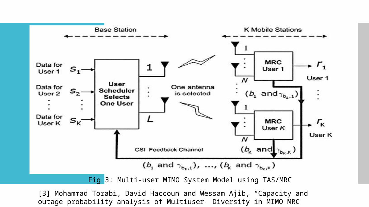
Fig 3: Multi-user MIMO System Model using TAS/MRC
[3] Mohammad Torabi, David Haccoun and Wessam Ajib, “Capacity and outage probability analysis of Multiuser Diversity in MIMO MRC Systems with Transmit Antenna Selection “.
SCHEDULING TECHNIQUE
Absolute SNR – based scheduling
An absolute SNR based scheduler at the base
station selects the best user among all the active
users.
Normalized SNR based proportional fair
scheduling
Scheduling scheme the base station selects the
user with the largest normalized SNR value.
FADING IN MIMO
Deviation of the attenuation affecting a
signal over certain propagation media[4].
The signal suffers loss in power due to
Shadowing
Reflection
Refraction
Scattering
Are represented by different mathematical
expressions
[4 ] Lars Ahlin & Jens Zander, Principles of Wireless Communications, pp.126.
NAKAGAMI-m FADING
The Nakagami-m distribution: Probability
distribution related to the gamma
distribution.
Two parameters:
a shape parameter, m (>1)
controlling spread parameter, Ω (=1)
Availability of a free parameter allows
flexibility.
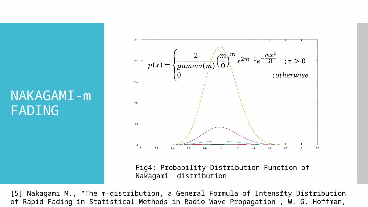
NAKAGAMI-m FADING
Fig4: Probability Distribution Function of Nakagami distribution
[5] Nakagami M., “The m-distribution, a General Formula of Intensity Distribution of Rapid Fading in Statistical Methods in Radio Wave Propagation”, W. G. Hoffman, Ed., Pergamon, Oxford, England, 1960
NAKAGAMI-m FADING
m-parameter allows to cover both severe
and weak fading.
High value of m causes a negative impact on
the capacity of Mu-MIMO systems.
Used to model
land-mobile
indoor mobile multipath propagation
scintillating ionosphere radio links
[6] Proakis. J. and Salehi. M. “Digital Communication”, 5th Ed, Mc-Graw Hill, International Edition, 2008, p 52, 53.
MODULATION TECHNIQUES
Binary Phase Shift Keying (BPSK)
Quadrature Phase Shift Keying (QPSK)
Quadrature Amplitude Modulation (QAM)
BIT ERROR RATE (BER)
Key parameter used in assessing systems
transmitting digital data.
Defined as the rate at which error occurs in a
transmission system.
Can be translated into a simple formula
=
BIT ERROR RATE (BER)
Errors in the data, compromise the integrity
of the system.
BER assesses the performance of the
system.
BER enables the actual performance of a
system in operation to be tested.
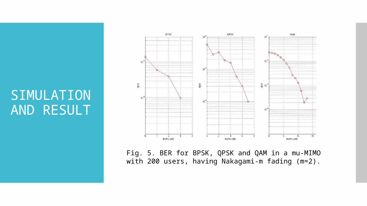
SIMULATION AND RESULT
Fig. 5. BER for BPSK, QPSK and QAM in a mu-MIMO with 200 users, having Nakagami-m fading (m=2).
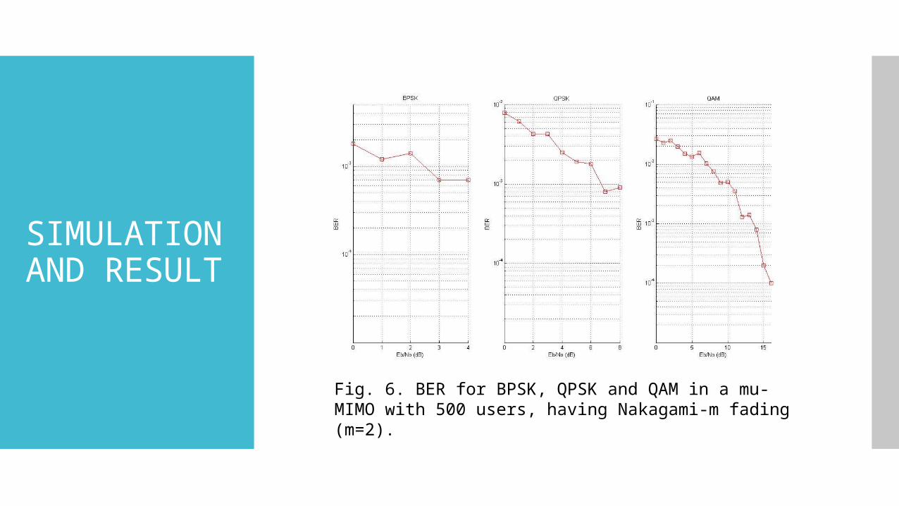
SIMULATION AND RESULT
Fig. 6. BER for BPSK, QPSK and QAM in a mu-MIMO with 500 users, having Nakagami-m fading (m=2).
INFERENCES
The energy per bit to noise power spectral
density ratio (EbNo) for
BPSK is from 0 to 4,
for QPSK is 0 to 8
for QAM is 0 to 16
No of users increases the error do decrease
The effect is more in BPSK and the least in QAM
Findings can be applied in designing of future
MIMO mobile devices
FUTURE ASPIRATIONS
Hardware appraisal of the simulated results
Comparison of practical & simulated results.