Embed Size (px)
Citation preview
975
Chapter 84
BERGEN TUNNELS REHABILITATION—A SUCCESS AFTER ALL
K. ZeidlerGall Zeidler Consultants, LLC
V. GallGall Zeidler Consultants, LLC
St. MergentimeMerco, Inc.
ABSTRACT
2001, the New Jersey Transit Authority commissioned the JV Merco-Obayashiwith the rehabilitation contract of the approximately 130-year-old, 4,200 ft long,partially brick- lined Bergen North Tunnel. The contract entailed the tunnelenlargement, shotcrete and rock dowels initial support according to the NATM, awaterproofing system, tunnel drainage and a cast-in-place concrete lining. The rockconditions encountered required design adaptations and significant modifications ofthe initial tunnel support. Flexibility, skill and extensive experience on the Authority’sand Contractor’s side finally lead to a success. This paper describes the operationsand design modifications carried out.
INTRODUCTION
As part of a major upgrading program, New Jersey Transit Corporation (NJT)decided to enlarge and rehabilitate the Bergen Tunnels North and South Tube.
The reconstruction of the Bergen Tunnel North tube became necessary due tomodern railway operation and safety requirements, increased clearance requirementsand the aging tunnel lining. Substantial leakages lead to operational problems, inparticular, due to ice accumulation during the winter season. Several repair efforts duringthe past decades including back-of-lining grouting, partial lining replacement byshotcrete and water diversion measures yielded unsatisfactory results for the long term.
The rehabilitation activities for the South Tube include local waterproofingmeasures and an upgrade of the electrical mechanical equipment. The rehabilitation ofthe South Tube will not be further detailed in this document.
PROJECT HISTORY
The approximately 4280 ft (1.3 km) long Bergen Tunnel North Tube wasconstructed between 1873 and 1879. Tunneling proceeded from the bottom of sixshafts and two portal approaches using hand drills and blasting methods (J. Burke,
RETC2003.book Page 975 Friday, April 11, 2003 9:37 AM
976 2003 RETC PROCEEDINGS
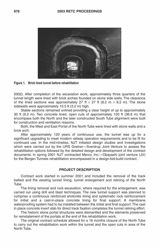
2002). After completion of the excavation work, approximately three quarters of thetunnel length were lined with brick arches founded on stone side walls. The clearanceof the lined sections was approximately 27 ft × 27 ft (8.2 m × 8.2 m). The stonesidewalls were approximately 10.5 ft (3.2 m) high.
Stable sections remained unlined providing a clear height of up to approximately30 ft (9.2 m). Two concrete lined, open cuts of approximately 120 ft (36.6 m) thatencompass both the North and the later constructed South Tube alignment were builtfor construction and ventilation reasons.
Both, the West and East Portal of the North Tube were lined with stone walls and abrick arch.
After approximately 120 years of continuous use, the tunnel was up for asignificant upgrading to meet modern railway operation requirements and to be fit forcontinued use. In the mid-nineties, NJT initiated design studies and investigationswhich were carried out by the URS Greiner—Sverdrup Joint Venture to assess therehabilitation options followed by the detailed design and development of the contractdocuments. In spring 2001 NJT contracted Merco, Inc.—Obayashi joint venture (JV)for the Bergen Tunnels rehabilitation encompassed in a design-bid-build contract.
PROJECT DESCRIPTION
Contract work started in summer 2001 and included the removal of the trackballast and the existing tunnel lining, tunnel enlargement and relining of the NorthTube.
The lining removal and rock excavation, where required for the enlargement, wascarried out using drill and blast techniques. The new tunnel support was planned tocomprise a continuous reinforced shotcrete lining and systematic rock reinforcementfor initial and a cast-in-place concrete lining for final support. A membranewaterproofing system had to be installed between the initial and final support. The castin place concrete invert slab for direct track fixation completes the tunnel relining effort.
The historic stone portal structures were dismantled and the elements preservedfor reinstatement of the portals at the end of the rehabilitation work.
The original contract schedule allowed for a 16 months closure of the North Tubeto carry out the rehabilitation work within the tunnel and the open cuts in area of theNorth Tube.
Figure 1. Brick lined tunnel before rehabilitation
RETC2003.book Page 976 Friday, April 11, 2003 9:37 AM
BERGEN TUNNELS REHABILITATION 977
GEOLOGICAL, GEOTECHNICAL AND STRUCTURAL CONDITIONS
The North Tube is located in hard, massive to fractured diabase. The degree offracturing varies from extremely wide joint spacing to closely spaced joints. Theintersection of joint sets in combination with the tunnel opening led to significantafter-break during blasting for both the tunnel construction and the tunnelrehabilitation. Joint bordered rock elements fell out from the exposed tunnel roof andshoulders after blasting.
Stone back-packing, grout and concrete backfill behind the brick and stone liningof up to 5 ft (1.5 m) was found behind the existing brick and stone linings. The backfillgenerally fell out after removal of the tunnel lining producing significant over-break(unintended excavation beyond the theoretical excavation line).
The brick lining was generally rather resistant against removal by variousexcavation methods. Blasting proved to be the most efficient method.
Groundwater inflow was either confined to individual rock mass discontinuities oroccurred in a more areal fashion in fractured zones and was frequently observed invicinity of the portals, ventilation shafts and open cuts after periods of precipitation
CONTRACT DESIGN
The following is an outline of the contractually specified rehabilitation methods.
East and West Portal Rehabilitation
The East and West Portal were supported by granite stone walls and brick arches.The face wall supported the soil and rubble backfill above the tunnel arch.
An approximately 10 to 15 ft (3.0 to 4.6 m) long section of soil backfill above theNorth Tube was anticipated. Grouted spiles were proposed to act as pre-support tostabilize the rock mass above the tunnel roof before any rock excavation commencedwithin the tunnel in this area. No rock support for the exposed rock cutting wallsresulting from the portal excavation was specified in the design.
A reinforced short shotcrete canopy with varying geometry was envisioned to formthe trumpet-like portal structure. After completion of the cast-in-place concrete finallining the stone portal facings and tunnel lining had to be rebuilt to match the originalportal arrangements.
Tunnel Rehabilitation
Voids behind the existing stone and brick lining were described, but not sufficientlyquantified. Tight areas in the exposed, lined sections and unlined sections had to beremoved to gain sufficient clear space for the new, larger tunnel cross section. Both thebrick removal and rock excavation are related to as excavation in this document.
Support Type I was specified for the tunnel sections without brick lining. SupportType II was designed for all brick lined sections with the exception of the areas aroundthe ventilation shafts and portals. The latter areas were covered by Support Types IIIaand IIIb for ventilation shaft and portal areas respectively. A continuous reinforcedshotcrete initial support lining of minimum 8 in (204 mm) thickness was planned to beinstalled throughout the entire tunnel. Systematic rock doweling was required forSupport Type II. The maximum excavation round length was limited to 6 ft (1.8 m) inSupport Types I and II and to 4 ft (1.2 m) in Support Types IIIa and IIIb. Grouted pre-spiling was required over a length of approximately 12 ft (3.7 m) surrounding theventilation shafts. Horizontal, grouted spiles applied as an umbrella from the portalscharacterized Support Type IIIb.
RETC2003.book Page 977 Friday, April 11, 2003 9:37 AM
978 2003 RETC PROCEEDINGS
Rock dowels in Support Type II were specified as fully grout bonded, 15 ft (4.6 m)long # 8 rebars, installed in a staggered 6 × 6 ft (1.8 × 1.8 m) pattern. Support Type Idid not include any rock mass reinforcement. All support elements had to be installedafter each excavation round prior to the next round in sequence. The spiles for the pre-support required in Support Type IIIa were specified as grouted, 15 ft (4.6 m) long # 8rebars. The grouted spiling umbrella for Support Type IIIb consisted of 40 ft (12.2 m)long, 2 in (50 mm) DIA perforated steel pipes, installed and grouted in pre-drilled holes.
The rehabilitation method specified for the ventilation shafts including shaft liningsecuring and backfill will not be detailed herein.
ACTUAL CONDITIONS ENCOUNTERED
East and West Portal Rehabilitation
Vegetation and top soil removal revealed that the length of the backfilled area atthe portals was with 35 ft (10.7 m) significantly longer than anticipated. The rock cutsthat had been created during the construction of the portals for the North Tubeextended far beyond those for the South Tube. It is interpreted that the weathered rockhad been excavated by blasting until sound rock and sufficient rock cover above thetunnel roof had been gained to establish a safe start situation for the tunnel miningusing blasting techniques of that time. Past experience showed that it takes the actualtunnel reconstruction to expose actual ground conditions surrounding the old tunnelstructure and portals. Similar experience has been gained by the authors on priorrehabilitation projects (Gall, V. et al., 1998).
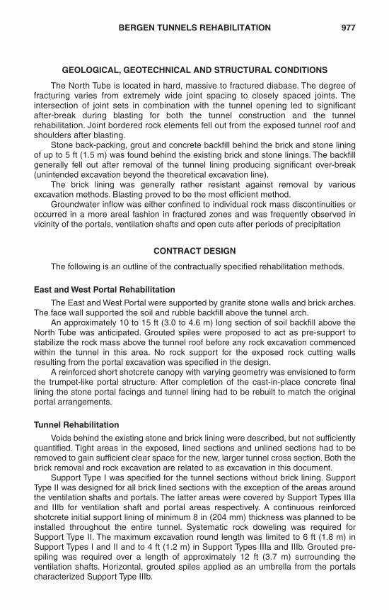
At the East Portal, the excavation revealed a cut that is limited by blocky rockmass in the north wall and the rock portal face and fractured rock and rubble backfilltowards the South Tube (see Figure 2). Loose rock mass conditions as consequenceof the blasting impact of the excavation was visible.
The rock at the West Portal was excavated in numerous benches until the tunnelroof elevation had been reached. From there, a sub-vertical rock face was excavateddown to the tunnel invert elevation. The north and south wall of the cut is formed byblocky rock mass with numerous drilling traces.
Figure 2. Situation at the East Portal after backfill and tunnel lining removal
RETC2003.book Page 978 Friday, April 11, 2003 9:37 AM
BERGEN TUNNELS REHABILITATION 979
Tunnel Rehabilitation
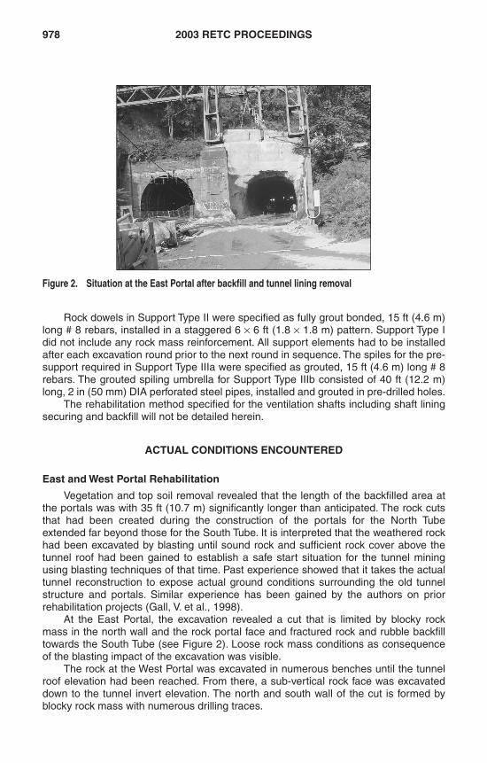
The removal of the brick and stone tunnel lining revealed blocky and fractured rockmass material that produced no to very small after-break. While the loose backpacking,grouted backpacking and concrete backfill behind the brick lining either fell outimmediately after the excavation or had to be removed for safety reasons using hoerams and excavators, the rock mass proved to be stable over the vast majority of theexcavation length with sufficient stand-up time capacity over longer periods. Onlylocalized areas of sheared and water discharging rock mass displayed some after-breakof fractured rock chunks that had to be stabilized immediately. The area in immediatevicinity of the ventilation shafts and open cuts exhibited more fractured rock mass withlimited stand-up-time capacity requiring early support installation. In some locations,rock slabs and blocks had to be scaled off or secured in place with rock dowels.
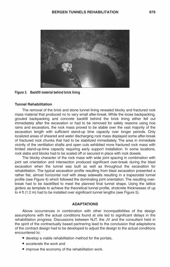
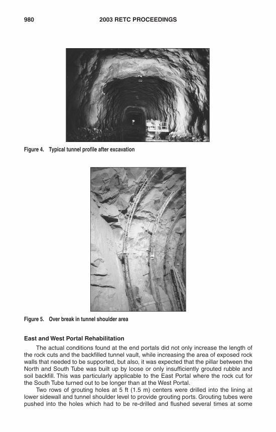
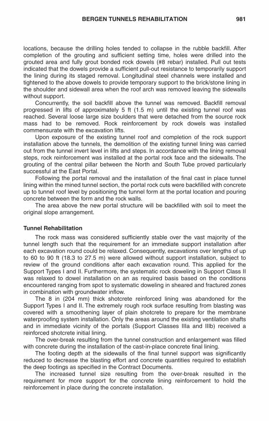
The blocky character of the rock mass with wide joint spacing in combination withjoint set orientation and intersection produced significant over-break during the blastexcavation when the tunnel was built as well as throughout the excavation forrehabilitation. The typical excavation profile resulting from blast excavation presented arather flat, almost horizontal roof with steep sidewalls resulting in a trapezoidal tunnelprofile (see Figure 4) which followed the dominating joint orientation. The resulting over-break had to be backfilled to meet the planned final tunnel shape. Using the latticegirders as template to achieve the theoretical tunnel profile, shotcrete thicknesses of upto 4 ft (1.2 m) had to be installed over significant tunnel lengths (see Figure 5).
ADAPTATIONS
Above occurrences in combination with other incompatibilities of the designassumptions with the actual conditions found at site led to significant delays in therehabilitation progress. Discussions between NJT, the JV and the consultant held inthe spirit of the contractually based partnering lead to the conclusion that adaptationsof the contract design had to be developed to adjust the design to the actual conditionsencountered to:
� develop a viable rehabilitation method for the portals,
� accelerate the work and
� improve the economy of the rehabilitation work.
Figure 3. Backfill material behind brick lining
RETC2003.book Page 979 Friday, April 11, 2003 9:37 AM
980 2003 RETC PROCEEDINGS
East and West Portal Rehabilitation
The actual conditions found at the end portals did not only increase the length ofthe rock cuts and the backfilled tunnel vault, while increasing the area of exposed rockwalls that needed to be supported, but also, it was expected that the pillar between theNorth and South Tube was built up by loose or only insufficiently grouted rubble andsoil backfill. This was particularly applicable to the East Portal where the rock cut forthe South Tube turned out to be longer than at the West Portal.
Two rows of grouting holes at 5 ft (1.5 m) centers were drilled into the lining atlower sidewall and tunnel shoulder level to provide grouting ports. Grouting tubes werepushed into the holes which had to be re-drilled and flushed several times at some
Figure 4. Typical tunnel profile after excavation
Figure 5. Over break in tunnel shoulder area
RETC2003.book Page 980 Friday, April 11, 2003 9:37 AM
BERGEN TUNNELS REHABILITATION 981
locations, because the drilling holes tended to collapse in the rubble backfill. Aftercompletion of the grouting and sufficient setting time, holes were drilled into thegrouted area and fully grout bonded rock dowels (#8 rebar) installed. Pull out testsindicated that the dowels provide a sufficient pull-out resistance to temporarily supportthe lining during its staged removal. Longitudinal steel channels were installed andtightened to the above dowels to provide temporary support to the brick/stone lining inthe shoulder and sidewall area when the roof arch was removed leaving the sidewallswithout support.
Concurrently, the soil backfill above the tunnel was removed. Backfill removalprogressed in lifts of approximately 5 ft (1.5 m) until the existing tunnel roof wasreached. Several loose large size boulders that were detached from the source rockmass had to be removed. Rock reinforcement by rock dowels was installedcommensurate with the excavation lifts.
Upon exposure of the existing tunnel roof and completion of the rock supportinstallation above the tunnels, the demolition of the existing tunnel lining was carriedout from the tunnel invert level in lifts and steps. In accordance with the lining removalsteps, rock reinforcement was installed at the portal rock face and the sidewalls. Thegrouting of the central pillar between the North and South Tube proved particularlysuccessful at the East Portal.
Following the portal removal and the installation of the final cast in place tunnellining within the mined tunnel section, the portal rock cuts were backfilled with concreteup to tunnel roof level by positioning the tunnel form at the portal location and pouringconcrete between the form and the rock walls.
The area above the new portal structure will be backfilled with soil to meet theoriginal slope arrangement.
Tunnel Rehabilitation
The rock mass was considered sufficiently stable over the vast majority of thetunnel length such that the requirement for an immediate support installation aftereach excavation round could be relaxed. Consequently, excavations over lengths of upto 60 to 90 ft (18.3 to 27.5 m) were allowed without support installation, subject toreview of the ground conditions after each excavation round. This applied for theSupport Types I and II. Furthermore, the systematic rock doweling in Support Class IIwas relaxed to dowel installation on an as required basis based on the conditionsencountered ranging from spot to systematic doweling in sheared and fractured zonesin combination with groundwater inflow.
The 8 in (204 mm) thick shotcrete reinforced lining was abandoned for theSupport Types I and II. The extremely rough rock surface resulting from blasting wascovered with a smoothening layer of plain shotcrete to prepare for the membranewaterproofing system installation. Only the areas around the existing ventilation shaftsand in immediate vicinity of the portals (Support Classes IIIa and IIIb) received areinforced shotcrete initial lining.
The over-break resulting from the tunnel construction and enlargement was filledwith concrete during the installation of the cast-in-place concrete final lining.
The footing depth at the sidewalls of the final tunnel support was significantlyreduced to decrease the blasting effort and concrete quantities required to establishthe deep footings as specified in the Contract Documents.
The increased tunnel size resulting from the over-break resulted in therequirement for more support for the concrete lining reinforcement to hold thereinforcement in place during the concrete installation.
RETC2003.book Page 981 Friday, April 11, 2003 9:37 AM
982 2003 RETC PROCEEDINGS
CONTRACTUAL SITUATION
The rehabilitation work was let under a design-bid-build contract format. Therefore,any changes initiated by NJT had to be in the form of Contract Change Orders.
For the changes related to the East and West Portal rehabilitation, the ownerreleased a Contract Change Order that included the new design of a rehabilitationmethod and the construction work to be carried out under a “Time and Materials”agreement with a limiting budget.
The adaptations implemented for the tunnel rehabilitation resulted in a significantincrease of the concrete and shotcrete quantities. The tunnel forms were in productionat the time when the design adjustments took effect and had to be modified to suit thechanged loading conditions.
The contract changes implemented for the tunnel rehabilitation were covered by aseries of Contract Change Orders.
CONCLUSION
This case history drastically demonstrates that in large scale tunnel reconstructionprojects, assumptions made during the design may be in divergence from the actualconditions found on site. It also shows that skilled, experienced and motivatedpersonnel is required to overcome larger or smaller discrepancies and to achieve theproject objectives.
Even though the design-bid-build contract provides limited contractual flexibility,the joint effort of all parties involved and the inherent flexibility of the NATM formed thebasis for a successful resolution of the problems and adaptations to the conditionsencountered.
A success after all.
REFERENCES
Burke, J. 2002. Bergen Tunnel Rehabilitation. World Tunnelling, March 2002Gall, V., Zeidler, K., Predis, T., Walter, J. 1998. Rehabilitation Concepts for Brick Lined
Tunnels in Urban Areas. World Tunnel Congress 98, April 1998, Sao Paulo, Brazil.
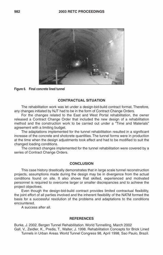
Figure 6. Final concrete lined tunnel
RETC2003.book Page 982 Friday, April 11, 2003 9:37 AM