Embed Size (px)
Citation preview

OWNER’S MANUALShallow Well Water System
Installation/Operation/PartsFor further operating, installation, or maintenance assistance:
Call 1-888-782-7483
© 2014 BE586 (02/28/14)
3869 0101
5PNP15H

Safety 2
INTRODUCTIONPlease read our instructions before installing and using your Shallow Well Water System. This will help you obtain the full benefits of the quality and convenience built into this equipment. It will also help you avoid any needless service expense resulting from causes beyond our control which are not covered by our warranty.
READ AND FOLLOW SAFETY INSTRUCTIONS!Carefully read and follow all safety instructions in this manual or on pump.
This is the safety alert symbol. When you see this symbol on your pump or in this manual, look for
one of the following signal words and be alert to the potential for personal injury!
warns about hazards that will cause serious personal injury, death or major property
damage if ignored.
warns about hazards that will or can cause serious personal injury, death or major property damage if ignored.
warns about hazards that will or can cause minor personal injury or property damage if ignored.
The word NOTICE indicates special instructions which are important but not related to hazards.
Never run pump dry. Running pump without water may cause pump to overheat, damaging seal and possibly causing burns to persons handling pump. Fill pump with water before starting.
Never run pump against closed discharge. To do so can boil water inside pump, causing hazardous pressure in unit, risk of explosion and possibly scalding persons handling pump.
Motor normally operates at high temperature and will be too hot to touch. It is protected from heat damage during operation by an automatic internal cutoff switch. Before handling pump or motor, stop motor and allow to cool for 20 minutes.
1. To avoid risk of serious bodily injury and property damage, read safety instructions carefully before installing pump.
2. Follow local and/or national plumbing and electrical codes when installing pump.
3. Keep well covered while installing pump to prevent leaves and other debris from falling into well, contaminating well and possibly damaging pump.
4. Protect pump and piping system from freezing. Allowing pump or water system to freeze could severely damage pump and voids warranty.
To avoid serious injury and equipment damage, limit system pressure to 75 pounds per square inch (PSI) or below at all times. Over-pressure can cause tank blowup; install relief valve capable of passing full pump volume at 75 PSI.
5. With a new well, test well for purity before use. Consult local Health Department for procedure.
Hazardous voltage. Can shock, burn, cause death, or start fires.
6. Disconnect electrical power source before installing or working on pump.
7. Ground pump with a ground wire run from grounding lug on motor to a grounded lead in the service panel.
8. Line voltage and frequency of electrical power supply must agree with motor nameplate.
9. Use of fuses or wire smaller than size recommended in owner’s manual can cause overheating, possible fires, and will void warranty.
BASIC TOOLS AND MATERIALS NEEDED
Plastic Pipe InstallationTools
Pipe Wrenches
Screwdriver
Knife or Saw to Cut Plastic Pipe
Tire Pressure Gauge
Materials
Plastic Pipe and Fittings (as required to complete job).
Teflon Tape (DO NOT use joint compound on plastic fittings).
Galvanized Steel Pipe InstallationTools
Pipe Wrenches
Screwdriver
Pipe Cutting and Threading Tools
Tire Pressure Gauge
Materials
Galvanized Pipe and Fittings (as required to complete job).
Pipe Joint Compound or PTFE Pipe Thread Sealant Tape
California Proposition 65 Warning This product and related accessories contain
chemicals known to the State of California to cause cancer, birth defects or other reproductive harm.
Safety 2

Safety 3Table of Contents 3
PageGeneral Safety .....................................................................................................2Warranty..............................................................................................................3Installation ........................................................................................................46Electrical ...........................................................................................................67Operation ............................................................................................................7Maintenance ..................................................................................................812Repair Parts .................................................................................................1314Troubleshooting .................................................................................................15
ATTACH ORIGINAL RECEIPT HERE FOR WARRANTY CONSIDERATION.
Limited WarrantyBERKELEY warrants to the original consumer purchaser (“Purchaser” or “You”) of the products listed below, that they will be free from defects in material and workmanship for the Warranty Period shown below.
Product Warranty Period
Water Systems:
Water Systems Products — jet pumps, small centrifugal pumps, submersible pumps and related accessories
whichever occurs first: 12 months from date of original installation, or 18 months from date of manufacture
ProSource™ Composite Tanks 5 years from date of original installation
ProSource™ Steel Pressure Tanks 5 years from date of original installation
ProSource™ EpoxyLined Tanks 3 years from date of original installation
Sump/Sewage/Effluent Products12 months from date of original installation, or 18 months from date of manufacture
Agricultural/Commercial:
Centrifugals – closecoupled motor drive, frame mount, SAE mount, engine drive, VMS, SSCX, SSHM, solids handling, submersible solids handling
12 months from date of original installation, or 24 months from date of manufacture
Submersible Turbines, 6” diameter and larger12 months from date of original installation, or 24 months from date of manufacture
Our limited warranty will not apply to any product that, in our sole judgement, has been subject to negligence, misapplication, improper installation, or improper maintenance. Without limiting the foregoing, operating a three phase motor with single phase power through a phase converter will void the warranty. Note also that three phase motors must be protected by threeleg, ambient compensated, extraquick trip overload relays of the recommended size or the warranty is void.Your only remedy, and BERKELEY’s only duty, is that BERKELEY repair or replace defective products (at BERKELEY’s choice). You must pay all labor and shipping charges associated with this warranty and must request warranty service through the installing dealer as soon as a problem is discovered. No request for service will be accepted if received after the Warranty Period has expired. This warranty is not transferable.BERKELEY SHALL NOT BE LIABLE FOR ANY CONSEQUENTIAL, INCIDENTAL, OR CONTINGENT DAMAGES WHATSOEVER.THE FOREGOING LIMITED WARRANTIES ARE EXCLUSIVE AND IN LIEU OF ALL OTHER EXPRESS AND IMPLIED WARRANTIES, INCLUDING BUT NOT LIMITED TO IMPLIED WARRANTIES OF MERCHANTABILITY AND FITNESS FOR A PARTICULAR PURPOSE. THE FOREGOING LIMITED WARRANTIES SHALL NOT EXTEND BEYOND THE DURATION PROVIDED HEREIN.Some states do not allow the exclusion or limitation of incidental or consequential damages or limitations on the duration of an implied warranty, so the above limitations or exclusions may not apply to You. This warranty gives You specific legal rights and You may also have other rights which vary from state to state.This Limited Warranty is effective June 1, 2011 and replaces all undated warranties and warranties dated before June 1, 2011.
In the U.S.: BERKELEY, 293 Wright St., Delavan, WI 53115 In Canada: 269 Trillium Dr., Kitchener, Ontario N2G 4W5

Safety 4Installation 4
MAJOR COMPONENTS AND WHAT THEY DO
Impeller and JetImpeller turns with motor shaft, causing water to fly out from its rim by centrifugal force. Impeller rotation creates a vacuum which pulls in more water. Part of the water is diverted back to the jet where it passes through the nozzle and venturi. This creates more vacuum to draw in more water.
In shallow wells (less than 25 feet deep), the vacuum created at the pump is enough to pull water to the pump. Therefore, for shallow well use the jet is built into the pump.
Pre-Charged TankThe tank serves two functions. It provides a reservoir of water under pressure and maintains a cushion of air pressure to prevent pipe hammering and possible damage to plumbing components. When water is drawn off through the house fixtures, the pressure in the tank is lowered and the pump starts.
Pressure SwitchThe pressure switch provides for automatic operation. Pump starts when pressure drops to 30 pounds and stops when pressure reaches 50 pounds.
Check Valve or Foot ValveInstall a check valve as close to well as possible on well point installations. A foot valve must be installed in the well on dug or cased wells. See Figures 2A and 2B (Pages 4 and 5). For long horizontal pipe runs, install check valve as close to well as possible (all types of wells).
INSTALLATION
Piping in the WellThe Shallow Well Water System can be installed on a dug well, cased well or with a driven point. In a dug or cased well, a foot valve and strainer should be installed for easy priming. It should be installed five to ten feet below the lowest level to which the water will drop while the pump is operating (pumping water level). To keep sediment from clogging the strainer, be sure it is five to ten feet above the bottom of the well. Before installing the foot valve, make sure that it works freely.
When using a foot valve, a priming tee and plug as shown in Figure 1, are recommended.
When installed on a driven point well, your Shallow Well Water System should have a check valve installed as shown in Figure 2A.
TABLE I – PUMP PERFORMANCE (IN GALLONS PER MINUTE)NOTE: This system is designed for pumping depths of 25 feet or less.
2485 0696
To HouseholdWater System
Pump PrimingPlug
From Well
Check Valve
Priming Teeand Plug
PressureSwitch
Figure 1 – Connections to water system
Pump Discharge Pumping Depth in Feet
Model Description Suct. Disch. Pressure PSI 5’ 10’ 15’ 20’ 25’
5PNP15H 1/2 HP S.W. Jet 11/4” 3/4” 40 5.2 5.0 4.6 4.3 3.2
Figure 2A – Driven point
Check valve
Steel drive pipe
Drive coupling
Drive point
Drive coupling
Drive point
Steel Drive Pipe
Check Valve

Safety 5
For a pump at sea level mounted directly over the well, be sure the total lift from the pumping water level to the pump does not exceed 25 feet. This will be less if the pump is offset from the well.
The maximum lift of any pump decreases at the rate of about 1’ less lift for every 1,000 feet of elevation above sea level. For example, at Denver, Colorado (Elev. 5,000’) the pump loses five feet of lift. The maximum depth from which it would pump water would therefore be 15 feet.
PUMP/TANK INSTALLATION
PumpNOTICE: Use Teflon tape supplied with the pump or PlastoJoint Stik1 for making all pipethread connections to the pump itself. To avoid stresscracking, do not use pipe joint compounds on the pump.
1. Wrap male pipe threads being attached to pump with one or two layers of PTFE pipe thread sealant tape. Cover entire threaded portion of pipe.
2. Do not overtighten threaded fittings in the plastic pump. Be sure you do not try to tighten joint past thread stop in pump port!
3. If leaks occur, remove fittings, clean off old tape, rewrap with two to three layers of tape and remake the connection. If joint still leaks, replace the fittings (fittings may be undersized).
4. Be sure to support all piping connected to the System.
Horizontal Piping from Well to PumpWhen the pump is offset more than 25 feet from the well, horizontal suction pipe size should be increased to reduce friction losses. Never install a suction pipe that is smaller than the suction tapping of the pump.
1-1/4” 1-1/2” 2”
Up to 25 Ft. 25 to 50 Ft. 50 to 200 Ft.
Discharge Pipe SizesWhen the pump is some distance from the house or point of water use, the discharge pipe size should be increased to reduce pressure losses caused by friction.
1” 1-1/4” 1-1/2”
Up to 25 Ft. 25 to 100 Ft. 100 to 600 Ft.
TankTank is precharged with 40 pounds per square inch (PSI) air pressure at the factory. Your tank requires an air charge of 28 PSI for proper operation; check tank pressure with tire gauge and adjust air charge as needed. Tank precharge should be checked annually; see instructions on Page 6.
In areas where the temperature is high for long periods of time, the tank precharge pressure may increase. This may reduce the tank drawdown (amount of water available per cycle). If this occurs, reduce the precharge pressure until it is 2 PSI below the pump cutin setting of the pressure switch (normally 30 PSI).
It is necessary to flush all air out of the piping system and water reservoir portion of the precharged tank. This is required on new installations, pumps requiring repriming and pumps that have been disassembled for service. Do this as follows:
1. Open faucets furthest from tank and allow pump to operate.
2. Air in the system will cause a sputtering flow; allow faucets to run until you have a steady, air free stream.
3. Open and close faucets repeatedly until you are sure all air has been removed.
4. If stream does not become steady, air may be leaking into the system; check for leaks in the piping on the suction side of the pump.
NOTICE: To prevent waterlogging, check tank air charge annually.
Installation 5
Plastic Pipe
Plastic Pipe
Foot Valveand Strainer
Coupling
Well Seal
Dug or Cased Well611 1293
Figure 2B – Dug or cased well
Disconnect power before working on pump, motor, pressure switch, or wiring.
Your Motor Terminal Board (under the motor end cover) and Pressure Switch look like one of those shown below.
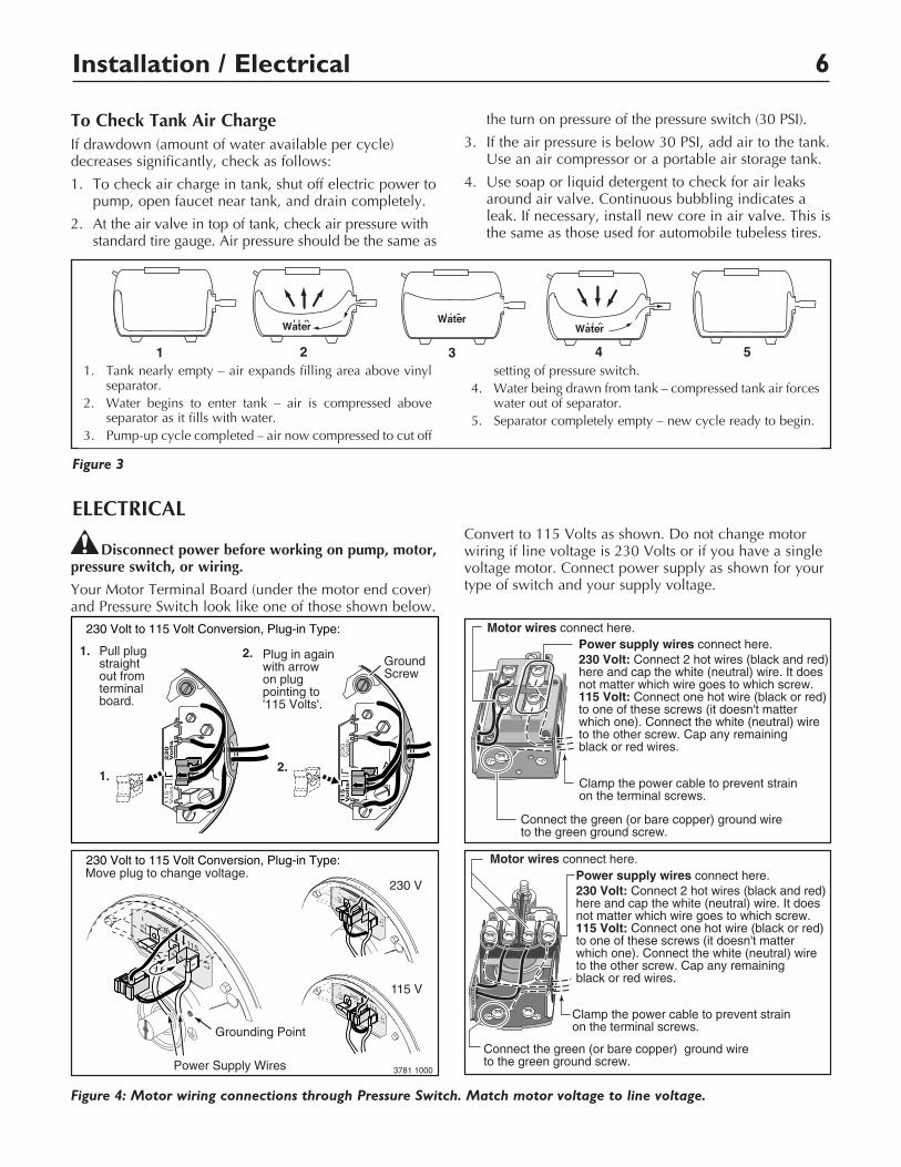
Convert to 115 Volts as shown. Do not change motor wiring if line voltage is 230 Volts or if you have a single voltage motor. Con nect power supply as shown for your type of switch and your supply voltage.
Installation / Electrical 6
To Check Tank Air ChargeIf drawdown (amount of water available per cycle) decreases significantly, check as follows:
1. To check air charge in tank, shut off electric power to pump, open faucet near tank, and drain completely.
2. At the air valve in top of tank, check air pressure with standard tire gauge. Air pressure should be the same as
the turn on pressure of the pressure switch (30 PSI).
3. If the air pressure is below 30 PSI, add air to the tank. Use an air compressor or a portable air storage tank.
4. Use soap or liquid detergent to check for air leaks around air valve. Continuous bubbling indicates a leak. If necessary, install new core in air valve. This is the same as those used for automobile tubeless tires.
H20H20 H20
612 1293
1 2 3 4 5 1. Tank nearly empty – air expands filling area above vinyl
separator. 2. Water begins to enter tank – air is compressed above
separator as it fills with water. 3. Pumpup cycle completed – air now compressed to cut off
setting of pressure switch. 4. Water being drawn from tank – compressed tank air forces
water out of separator. 5. Separator completely empty – new cycle ready to begin.
Figure 3
WaterWater
Water
Figure 4: Motor wiring connections through Pressure Switch. Match motor voltage to line voltage.
Move plug to change voltage.
115 V
230 V
Power Supply Wires
L1
L2
230
115
L1
L2
230
115
L1
L2
230
115
Grounding Point
3781 1000
230 Volt to 115 Volt Conversion, Plug-in Type:
230 Volt to 115 Volt Conversion, Plug-in Type:
Pull plug straightout from terminalboard.
1.
1.
2.
2.
Plug in againwith arrow on plug pointing to'115 Volts'.
A
L1
230
Vo
lts
115
Volts
A
L1
230
Volts
115
Vo
lts
GroundScrew
Clamp the power cable to prevent strain on the terminal screws.
Connect the green (or bare copper) ground wire to the green ground screw.
Motor wires connect here.
Clamp the power cable to prevent strain on the terminal screws.
Connect the green (or bare copper) ground wire to the green ground screw.
Motor wires connect here.
3187 0398
Power supply wires connect here. 230 Volt: Connect 2 hot wires (black and red)here and cap the white (neutral) wire. It doesnot matter which wire goes to which screw. 115 Volt: Connect one hot wire (black or red)to one of these screws (it doesn't matter which one). Connect the white (neutral) wire to the other screw. Cap any remaining black or red wires.
Power supply wires connect here. 230 Volt: Connect 2 hot wires (black and red)here and cap the white (neutral) wire. It doesnot matter which wire goes to which screw. 115 Volt: Connect one hot wire (black or red)to one of these screws (it doesn't matter which one). Connect the white (neutral) wire to the other screw. Cap any remaining black or red wires.
ELECTRICAL

Safety 7
Hazardous voltage. Can shock, burn, or kill. Connect ground wire before connecting power sup-ply wires. Use the wire size (including the ground wire) specified in the wiring chart. If possible, connect the pump to a separate branch circuit with no other appliances on it.
Explosion hazard. Do not ground to a gas supply line.
WIRING CONNECTIONS
Fire hazard. Incorrect voltage can cause a fire or seriously damage the motor and voids the warranty. The supply voltage must be within ±10% of the motor nameplate voltage.
NOTICE: Dualvoltage motors are factory wired for 230 volts. If necessary, reconnect the motor for 115 volts, as shown. Do not alter the wiring in single voltage motors.
Install, ground, wire, and maintain your pump in compliance with the National Electrical Code (NEC) or the Canadian Electrical Code (CEC), as applicable, and with all local codes and ordinances that apply. Consult your local building inspector for code information.
Connection Procedure:1. Connect the ground wire first as shown in Figure 4.
The ground wire must be a solid copper wire at least as large as the power supply wires.
2. There must be a solid metal connection between the pressure switch and the motor for motor grounding protection. If the pressure switch is not connected to the motor, connect the green ground screw in the switch to the green ground screw under the motor end cover. Use a solid copper wire at least as large as the power supply wires.
3. Connect the ground wire to a grounded lead in a service panel, to a metal underground water pipe, to a metal well casing at least ten feet (3M) long, or to a ground electrode provided by the power company or the hydro authority.
4. Connect the power supply wires to the pressure switch as shown in Figure 4.
OPERATIONPriming the PumpNOTICE: To prevent damage to internal parts, do not start motor until pump has been filled with water.
To prime pump:
1. Remove priming plug (Figure 1, Page 4).
2. Fill pump with water.
3. Replace priming plug, using PTFE pipe thread sealant tape on plug threads; tighten plug.
4. Start the pump. Water should be pumped in 12 minutes. If not, repeat steps 1, 2 and 3.
On shallow depths to water (10 feet or less), the pump will probably prime the first time after following steps 1 through 4 above.
From 10 to 25 foot depths, you might have to shut off the pump and repeat steps 1, 2 and 3 several times.
5. If, after priming pump several times, no water is pumped, check the following:
A. Be sure suction pipe is in the water.
B. Be sure suction pipe does not leak.
C. Be sure that pump is not trying to lift water too high (see “Piping in the Well”, Page 4).
D. As long as foot valve and check valve function correctly and suction pipe does not develop leaks, pump should not need repriming in normal service.
Preparing to Start the Pump – Deep Well 7Electrical / Operation 7
Table II Wiring Chart – Recommended Wire and Fuse Sizes
Distance in Feet from Motor to Meter
Branch 0’ 101’ 201’ 301’ 401’ Max. Fuse* to to to to to Motor Load Rating 100’ 200’ 300’ 400’ 500’
Horsepower Volts Amps. Amps Wire Size
1/2 115/230 8.8/4.4 15/15 14/14 12/14 10/14 8/14 8/12

Safety 8
LubricationIt is not necessary to lubricate the pump or its motor. The motor bearings are lubricated for life. The mechanical shaft seal in the pump is water lubricated and selfadjusting.
Draining for Winter
Risk of electric shock. Disconnect power before working on unit.
Pump should be drained whenever it is disconnected from service or is in danger of freezing.
1. DISCONNECT POWER.
2. Open faucet and relieve all pressure on system before proceeding.
3. Disconnect pressure switch tube (Key No. 15, Page 13) at barbed elbow on pressure switch (Key No. 26) and allow tube to drain.
4. Unscrew barbed elbow (Key No. 14) from pump body and allow pump to drain. If necessary to drain completely, tilt pump.
5. Remove priming plug to vent pump; disconnect hose (Key No. 8, Page 14) at tank end and drain pressure tank and all piping to a point below the frost line.
6. Be sure to drain any piping that may be cut off from normal system drain due to check valve installation.
Vinyl Bag Replacement
Be sure ALL air pressure has been released from tank before removing nuts from flange. Failure to do this may result in serious or fatal injury. Do not attempt to open tank unless all pressure has been relieved!
Risk of electric shock. Disconnect power before working on unit.
1. DISCONNECT POWER TO PUMP.
2. Drain system as follows:
A. Open faucet closest to tank.
B. Remove hose (Key No. 8, Page 14) from tank elbow.
3. Relieve (expel) ALL air pressure in system by removing valve core.
4. Disconnect outside piping from tank and pump.
To avoid serious or fatal injury, be sure all air pressure has been released from tank before proceeding to step 5.
5. Remove nuts from inlet flange (Key No. 4, Page 14). Tap inlet flange to break seal. Remove flange.
6. Wherever convenient, hold bag with pliers and cut with singleedge razor blade or sharp knife. Bag will not come out in one piece. Continue pulling and cutting until bag is removed.
7. Clean and dry inside of tank.
8. Place replacement bag on a clean surface with opening up. Flatten bag and force air out.
9. Tightly roll bag towards center opening.
10. Before center opening is covered up, force air out of remaining portion of bag. Finish rolling bag.
11. To make bag easier to insert into tank, sprinkle outside of bag with talcum powder.
12. Being careful not to break valve, stand tank on end. Push tightly rolled bag into tank.
13. Reach into bag and push out sidewalls. You need not remove all wrinkles.
14. Clean center opening ring on bag and lip on tank.
15. Pull ring on bag through tank opening and fit over tank lip. BE SURE it seats properly in groove on tank lip.
16. Clean sealing surface of inlet flange and place on studs.
17. NOTICE: Tighten nuts as follows:
A. Hand tighten all nuts.
B. Tighten one nut snug.
C. Tighten opposite nut snug.
D. Proceed, tightening opposite pairs to a snug fit.
E. Recheck all nuts, using same pattern. Be sure all nuts are tight and you have a good seal.
NOTICE: Do not overtighten; you may twist studs off of tank. If you have a torque wrench, tighten to 85 inchpounds torque.
18. Stand tank on feet and reconnect piping.
19. Recharge tank to proper air pressure (see Page 6).
20. Reconnect hoses and pressure switch tube; prime pump (above).
Air Valve Replacement1. Follow steps 1 through 5 under “Vinyl Bag
Replacement”.
2. Cut valve off as close to tank as possible. Push re maining portion back into tank.
3. Tip tank on end and BE SURE all water is drained from bag.
4. Carefully remove bag ring from lip on tank opening and push bag ring back into tank; reach in around it and remove cut off portion of valve from tank.
5. Wipe a thin film of soapy solution on replacement valve and from inside tank insert in hole in top of tank.
Maintenance 8

Maintenance 9
6. Pull valve through hole with pliers or a valve tool (available at your local filling station or Automotive Center).
7. Follow steps 14 through 20 under “Vinyl Bag Re placement”, Page 8, to reinstall bag in tank.
Testing for Bag Leakage1. Follow steps 1 through 4 under “Vinyl Bag
Replacement”, Page 8.
2. Tip tank on end, valve down. Be careful not to break valve!
3. If bag leaks, water will run out of valve. If so, replace bag as instructed above.
DISASSEMBLY AND ASSEMBLY OF PUMP
Risk of electrical shock. Be sure unit is grounded and power disconnected before attempting any work on pump or motor.
Your pump is designed for ease in servicing. Should repair or replacement of the motor or seal be needed, the pump and piping do not need to be disconnected or disturbed.
1. Disassemble pump as follows:
A. Disconnect power.
B. Remove pressure switch tube from pump body and allow pump to drain.
C. Remove four hexnuts and lockwashers (Key Nos. 24 and 23, Page 13) which hold the pump body to the motor.
D. Remove motor, seal plate, impeller, rubber pad and diffuser (Key Nos. 1, 3, 7, 8 and 9, Page 13) as a unit. You may have to pry gently with two screwdrivers between the motor flange and the pump body to separate pump and motor.
2. Reassembly of pump:
A. Install ORing gasket on seal plate (Key Nos. 5 and 3, Page 13).
B. Pick up a small amount of petroleum jelly on one finger and spread evenly over seal plate and venturi ORing gasket for lubrication during reassembly. Be careful not to nick or tear ORing.
C. Replace motor onto pump body; be sure rubber pad (Key No. 8, Page 13) stays in place on top of diffuser. Remount base on lower studs. Tighten four hexnuts and lockwashers snugly (3545 inchlbs. torque). Do not overtighten.
D. Replace pressure switch tubing and motor wiring.
E. Prime pump according to instructions above.
F. Check for leaks.
Removing Motor for Service and Replacing Shaft SealIf it is necessary to separate motor and seal plate, always replace the shaft seal. We suggest you purchase this item, U1096A, and have it on hand for future use.
NOTICE: The seal consists of two parts, a rotating member and a ceramic seat. The surfaces of the seal are easily damaged. Read instructions carefully.
Remove motor as follows:
1. Disassemble pump per instructions above.
2. Remove diffuser and impeller as follows (Key Nos. 9 and 7, Page 13).
A. Remove screws holding diffuser.
B. Loosen two screws and remove motor canopy from motor (Key No. 1, Page 13).
C. Place 7/16” open end wrench on motor shaft flat.
D. Turn impeller counterclockwise when facing it.
3. Remove seal plate from motor by inserting two screwdrivers between the seal plate and the motor flange. Pry seal plate off motor flange. This will force rotating portion of seal off of shaft.
NOTE: Be sure you do not scratch shaft!
See Figures 5 & 6.
Figure 5
Figure 6
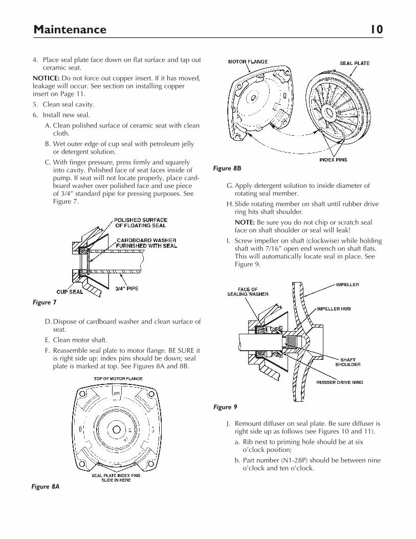
Maintenance 10
4. Place seal plate face down on flat surface and tap out ceramic seat.
NOTICE: Do not force out copper insert. If it has moved, leakage will occur. See section on installing copper insert on Page 11.
5. Clean seal cavity.
6. Install new seal.
A. Clean polished surface of ceramic seat with clean cloth.
B. Wet outer edge of cup seal with petroleum jelly or detergent solution.
C. With finger pressure, press firmly and squarely into cavity. Polished face of seat faces inside of pump. If seat will not locate properly, place cardboard washer over polished face and use piece of 3/4” standard pipe for pressing purposes. See Figure 7.
D. Dispose of cardboard washer and clean surface of seat.
E. Clean motor shaft.
F. Reassemble seal plate to motor flange. BE SURE it is right side up: index pins should be down; seal plate is marked at top. See Figures 8A and 8B.
G. Apply detergent solution to inside diameter of rotating seal member.
H. Slide rotating member on shaft until rubber drive ring hits shaft shoulder.
NOTE: Be sure you do not chip or scratch seal face on shaft shoulder or seal will leak!
I. Screw impeller on shaft (clockwise) while holding shaft with 7/16” open end wrench on shaft flats. This will automatically locate seal in place. See Figure 9.
J. Remount diffuser on seal plate. Be sure diffuser is right side up as follows (see Figures 10 and 11).
a. Rib next to priming hole should be at six o’clock position;
b. Part number (N128P) should be between nine o’clock and ten o’clock.
Figure 7
Figure 8A
Figure 8B
Figure 9

Maintenance 11
c. Both mounting screws must engage screw holes in seal plate. See Figure 10.
d. Be sure rubber pad (Figure 10; Key No. 8, Page 13) stays in place on top of diffuser.
Installing Copper InsertNOTE: If the copper insert (Key No. 4, Page 13) moves or shifts during seal removal, it should be removed and reinstalled.
1. Remove copper insert as shown in Figure 12. do not deform.
2. Replace copper insert:
A. Clean off surplus Permatex* from around insert cavity. Be careful not to scratch or mark the machined bore. It is important that this area be clean so no old Permatex lodges behind the new insert and causes improper seating.
B. Place a small amount of No. 2 nonhardening Permatex on surface of insert as shown. Smooth out with finger. See Figure 13.
C. Pull insert into cavity as shown in Figure 14.
D. Clean out any surplus Permatex from insert cavity where new seal will be located. See Figure 15.
Figure 10
Figure 11
Figure 12
Figure 13
Wipe on small amount of�non-hardening Permatex�
on this surface
756 0993
Figure 14
7/8" Socket
Bolt
1-3/8" O.D.�Washer
038 0893
Figure 15
Remove�Surplus�Permatex
Properly�Seated
039 0893

Maintenance 12
Cleaning Impeller1. Follow steps 1A through 1D under “Disassembly
and Assembly of Pump” on Page 9.
2. Remove diffuser and impeller from pump per instructions under “Removing Motor for Service and Replacing Shaft Seal” on Page 9.
3. Clean impeller and reassemble impeller and diffuser per instructions under “Removing Motor for Service and Replacing Shaft Seal” on Page 9.
Cleaning Shallow Well JetTo remove debris from venturi or nozzle, proceed as follows:
1. Disassemble pump per instructions on Page 9.
2. Turn venturi counterclockwise and remove it. The nozzle is now exposed. Remove it using a 5/8” hex socket wrench with extension. Turn counterclockwise. If socket wrench is not available, insert an ice pick or similar pointed tool carefully into the nozzle. This will dislodge debris.
3. Flush out the debris by running water through the nozzle in the same direction as the dislodging tool was inserted.
4. Replace nozzle and venturi. Do not overtighten!
5. Reassemble per pump instructions on Page 9.
HELPFUL HINTS
How to Handle a Gaseous WellIn some areas well water contains gases which must be allowed to escape before the water is used. This can be done as shown in Figure 16.
A good way of delivering gasfree water is to suspend a pipe, closed at the bottom and open at the top, surrounding the suction pipe. Since the gases rise in the well casing, the water sucked down through the pipe and into the suction pipe is free of gas. This type of well must be vented to the outside of any enclosure.
Notto
Scale
Pipe strap orwire to holdpipe sleeve
Pipesleeve
Pipecap
Tailpipe
Footvalve
2369 0396
Gasesrise to surface
Figure 16

Repair Parts 13
Repair Parts
1
2305 0296 BE
AVCPort
23
45
67 8
910
11
121314
15
1617
1819
2021
2223
24
25
26
2728
Key No. Description Qty. Part Number
1# Motor 115/230V 1 A100CLL 2 Water Slinger 1 C692 3* Seal Plate Assembly 1 N10312PSS 4 Seal Plate Insert 1 J32SS 5 ORing 1 U9390 6 Shaft Seal 1 U1096A 7 Impeller 1 J10540PF 8 Rubber Pad 1 C3541 9 Diffuser 1 N128P 10 Capscrew #1016 Hex Head 2 U30738SS 11** Pump Body Assembly 1 N17635P 12 Pump Body 1 N7635P 13 Pipe Plug 1/8” NPT 1 WC7841T 14 90° Hose Barb 1 U11186T 15 Pressure Switch Tube 1 U37670P 16 Gasket 1 J2018 17 Pump Body Jet Insert 1 N7629P 18 Capscrew #1016 4 U30742SS 19 Nozzle #45 1 N34P19 20 Venturi 1 N32P66 21 ORing 1 U9201 22 Base Assembly Painted 1 J1049F 23 Lock Washer 3/8” 4 U4312ZP 24 Nut 3/8” 16 4 U3638ZP 25 Rubber Pad 1 C355 26 Pressure Switch 1 U2171216 27 Locknut 1/2” 1 U36112ZP 28 Connector 1/2” 1 L435C
# For repair or service to motors, always give the motor model number and any other data found on the motor model plate.
* Includes Key No. 4. ** Includes Key Nos. 12, and 16 through 21.

Repair Parts 14
Repair Parts - Tank Only
1
3
2
7
5
9
10
11
4
2433 0596 BE
6
7
8
Key No. Description Qty. Part Number
1 Air Valve Cover 1 U31380P 2 Air Valve and Cap 1 U212160 3 Replacement Tank 1 PS15HS05 4 Inlet Flange 1 U31442P 5 Nut, 5/1618 Hex 6 U36202BT 6 Elbow, 3/4” MPT x 1” Insert 1 U78770P 7 Clamp 2 U1955SS 8 Hose 1” x 23” 1 U7437X 9 Discharge Tee with Barb 1 U78972P 10 1/2” x 1/8” NPT Reducer Bushing 1 U78107PT 11 1/8” NPT Pipe Plug 1 WC7841T • Diaphragm 1 U20-7
• Notillustrated. † Standard hardware item, may be purchased locally.

Troubleshooting 15Troubleshooting 15
TROUBLE POSSIBLE CAUSES REMEDIES Motor will not run 1. Disconnect switch is off 1. Be sure switch is on 2. Fuse is blown 2. Replace fuse 3. Starting switch is defective 3. Replace starting switch 4. Wires at motor are loose, 4. Refer to instructions on wiring disconnected, or wired incorrectly 5. Motor is wired incorrectly 5. Refer to instructions on wiring 6. Pressure switch contacts are dirty 6. Clean by sliding piece of plain paper between contacts
Motor runs hot and *1. Motor is wired incorrectly 1. Refer to instructions on wiring overload kicks off 2. Voltage is too low 2. Check with power company. Install heavier wiring if wire size is too small. See wiring instructions 3. Pump cycles too frequently 3. See section below on too frequent cycling
Motor runs but no *1. Pump in a new installation did 1. In new installation: water is delivered not pick up prime through: a. Improper priming a. Reprime according to instructions b. Air leaks b. Check all connections on suction line and jet c. Leaking foot valve c. Replace foot valve *2. Pump has lost its prime through: 2. In installation already in use: a. Air leaks a. Check all connections on suction line, jet and shaft seal b. Water level below suction of pump b. Lower suction line into water and reprime. If receding water level in a shallow well operation exceeds suction lift, a deep well pump is needed 3. Jet or impeller is plugged 3. Clean jet or impeller according to instructions 4. Check valve or foot valve is stuck 4. Replace check valve or foot valve in closed position 5. Pipes are frozen 5. Thaw pipes. Bury pipes below frost line. Heat pit or pump house 6. Foot valve and/or strainer are 6. Raise foot valve and/or strainer above well bottom buried in sand or mud
Pump does not 1. Water level in well is lower than 1. A deep well jet pump may be needed (over 25 ft. deliver water to full estimated to water) capacity (also check 2. Steel piping (if used) is corroded or 2. Replace with Plastic Pipe where possible, otherwise point 3 immediately limed, causing excess friction with new steel pipe above) 3. Offset piping is too small in size 3. Use larger offset piping
Pump pumps water 1. Pressure switch is out of adjustment 1. Adjust or replace pressure switch but does not shut off or contacts are “frozen” 2. Faucets have been left open 2. Close faucets 3. Jet or impeller is clogged 3. Clean jet or impeller 4. Motor is wired incorrectly 4. Refer to instructions on wiring 5. Water level in well is lower than 5. Check possibility of using a deep well jet pump estimated
Pump cycles too 1. Pipes leak 1. Check connections, replace pipe fittings frequently 2. Faucets or valves are open 2. Close faucets or valves 3. Foot valve leaks 3. Replace foot valve 4. Pressure switch is out of adjustment 4. Adjust or replace pressure switch 5. Air charge too low in 5. Disconnect electrical power and open faucets until all precharged tank pressure is relieved. Using automobile tire pressure gauge, check air pressure in tank at the valve stem located at top of tank. If less than 30 pounds, pump air into tank from outside source, until 30 pounds pressure is reached. Check air valve for leaks, using soapy solution, and replace core if necessary
Air spurts from 1. Pump is picking up prime 1. As soon as pump picks up prime, all air will be ejected faucets 2. Leak in suction side of pump 2. Check suction piping, make sure joints are not sucking air 3. Well is gaseous 3. Change installation as described in manual 4. Intermittent overpumping of well 4. Lower foot valve if possible, otherwise restrict discharge side of pump
(*Note: Check prime before looking for other causes. Unscrew priming plug and see if there is water in priming hole)

16