Embed Size (px)
Citation preview
Engineering DesignProcess for BEST Robotics
JANNE ACKERMANCOLLIN COUNTY (COCO) BEST & BEST OF TEXAS ROBOTICS

Agenda
►Getting Started
►Lessons Learned
►Design Process
►Engineering Mechanics
2Copyright © 2017 BEST Robotics, Inc. All rights reserved.
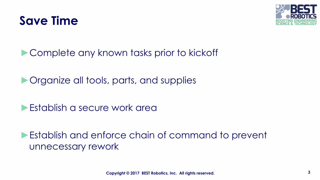
Save Time
►Complete any known tasks prior to kickoff
►Organize all tools, parts, and supplies
►Establish a secure work area
►Establish and enforce chain of command to prevent unnecessary rework
3Copyright © 2017 BEST Robotics, Inc. All rights reserved.
Strategy
►STRATEGY IS AS IMPORTANT AS A FUNCTIONAL MACHINE
►Complete machine early in order to get practice.
►Participate in Mall Day but also visit other hubs’ Mall Day.
4Copyright © 2017 BEST Robotics, Inc. All rights reserved.
Documentation
►DOCUMENTATION IS ESSENTIAL
► If it isn’t documented, it didn’t happen – document everything
►Have team notebooks and an overall master notebook
►Complete engineering notebook in stages as they occur
5Copyright © 2017 BEST Robotics, Inc. All rights reserved.

Schedule
6Copyright © 2017 BEST Robotics, Inc. All rights reserved.
WHEN TASK/ACTION
Week 1 Understand requirementsConcept selected
Week 2 Mock up completeCourse complete
Week 3 Prototype robot complete
Week 4 “Production” robot completeBegin drawings
Week 5 Drive practiceStrategy development
Week 6 Drive practiceComplete drawings
BEST Design Process
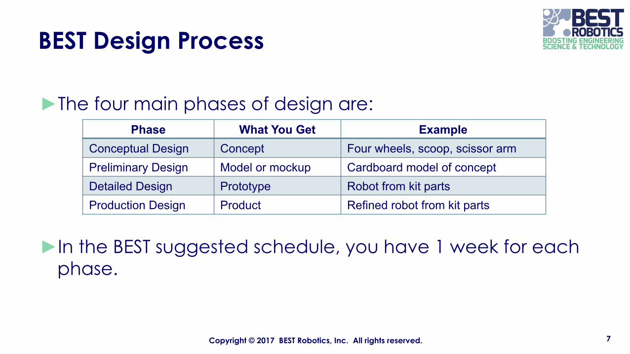
►The four main phases of design are:
►In the BEST suggested schedule, you have 1 week for each phase.
7Copyright © 2017 BEST Robotics, Inc. All rights reserved.
Phase What You Get ExampleConceptual Design Concept Four wheels, scoop, scissor armPreliminary Design Model or mockup Cardboard model of conceptDetailed Design Prototype Robot from kit partsProduction Design Product Refined robot from kit parts
Conceptual Design
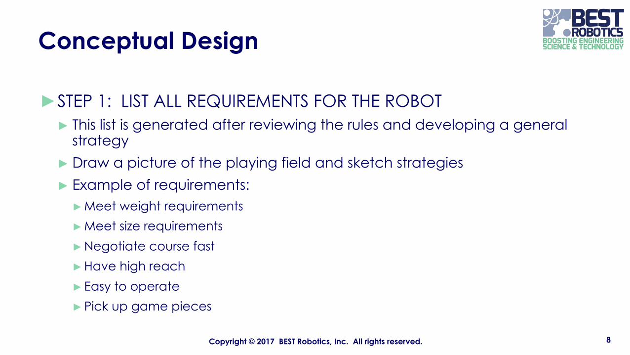
►STEP 1: LIST ALL REQUIREMENTS FOR THE ROBOT► This list is generated after reviewing the rules and developing a general
strategy ► Draw a picture of the playing field and sketch strategies► Example of requirements:►Meet weight requirements►Meet size requirements►Negotiate course fast►Have high reach►Easy to operate►Pick up game pieces
8Copyright © 2017 BEST Robotics, Inc. All rights reserved.
Conceptual Design
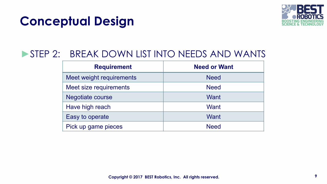
►STEP 2: BREAK DOWN LIST INTO NEEDS AND WANTS
9Copyright © 2017 BEST Robotics, Inc. All rights reserved.
Requirement Need or WantMeet weight requirements NeedMeet size requirements NeedNegotiate course WantHave high reach WantEasy to operate WantPick up game pieces Need
Conceptual Design
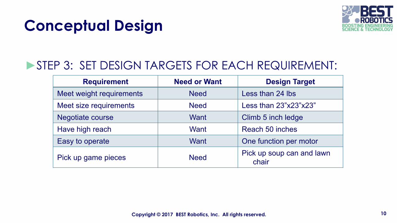
►STEP 3: SET DESIGN TARGETS FOR EACH REQUIREMENT:
10Copyright © 2017 BEST Robotics, Inc. All rights reserved.
Requirement Need or Want Design TargetMeet weight requirements Need Less than 24 lbsMeet size requirements Need Less than 23”x23”x23”Negotiate course Want Climb 5 inch ledgeHave high reach Want Reach 50 inchesEasy to operate Want One function per motor
Pick up game pieces Need Pick up soup can and lawn chair
Conceptual Design
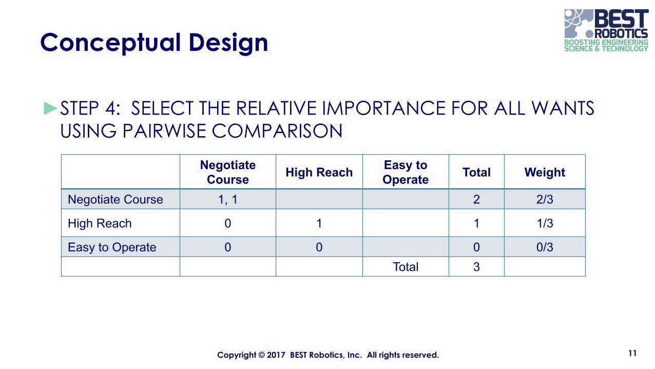
►STEP 4: SELECT THE RELATIVE IMPORTANCE FOR ALL WANTS USING PAIRWISE COMPARISON
11Copyright © 2017 BEST Robotics, Inc. All rights reserved.
Negotiate Course High Reach Easy to
Operate Total Weight
Negotiate Course 1, 1 2 2/3
High Reach 0 1 1 1/3
Easy to Operate 0 0 0 0/3Total 3
Conceptual Design
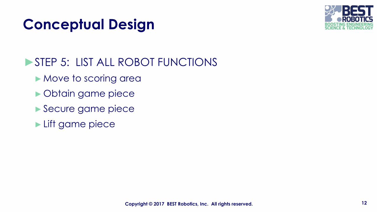
►STEP 5: LIST ALL ROBOT FUNCTIONS►Move to scoring area►Obtain game piece►Secure game piece► Lift game piece
12Copyright © 2017 BEST Robotics, Inc. All rights reserved.
Conceptual Design
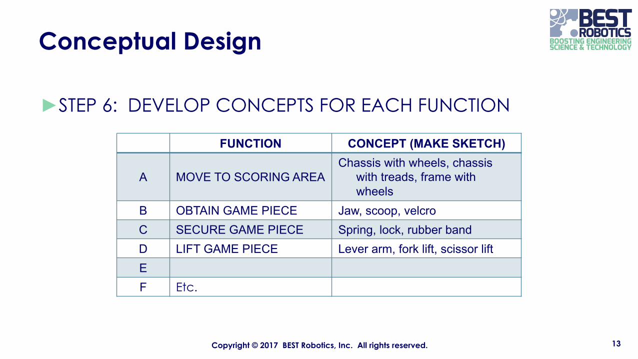
►STEP 6: DEVELOP CONCEPTS FOR EACH FUNCTION
13Copyright © 2017 BEST Robotics, Inc. All rights reserved.
FUNCTION CONCEPT (MAKE SKETCH)
A MOVE TO SCORING AREAChassis with wheels, chassis
with treads, frame with wheels
B OBTAIN GAME PIECE Jaw, scoop, velcroC SECURE GAME PIECE Spring, lock, rubber bandD LIFT GAME PIECE Lever arm, fork lift, scissor liftEF Etc.
Conceptual Design
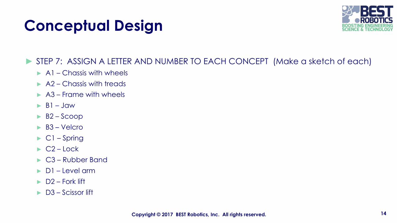
► STEP 7: ASSIGN A LETTER AND NUMBER TO EACH CONCEPT (Make a sketch of each)► A1 – Chassis with wheels► A2 – Chassis with treads► A3 – Frame with wheels► B1 – Jaw► B2 – Scoop► B3 – Velcro► C1 – Spring► C2 – Lock► C3 – Rubber Band► D1 – Level arm► D2 – Fork lift► D3 – Scissor lift
14Copyright © 2017 BEST Robotics, Inc. All rights reserved.
Conceptual Design
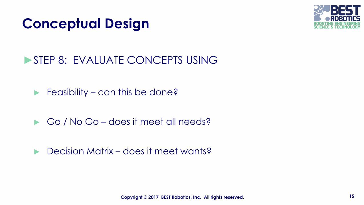
►STEP 8: EVALUATE CONCEPTS USING
► Feasibility – can this be done?
► Go / No Go – does it meet all needs?
► Decision Matrix – does it meet wants?
15Copyright © 2017 BEST Robotics, Inc. All rights reserved.
Conceptual Design
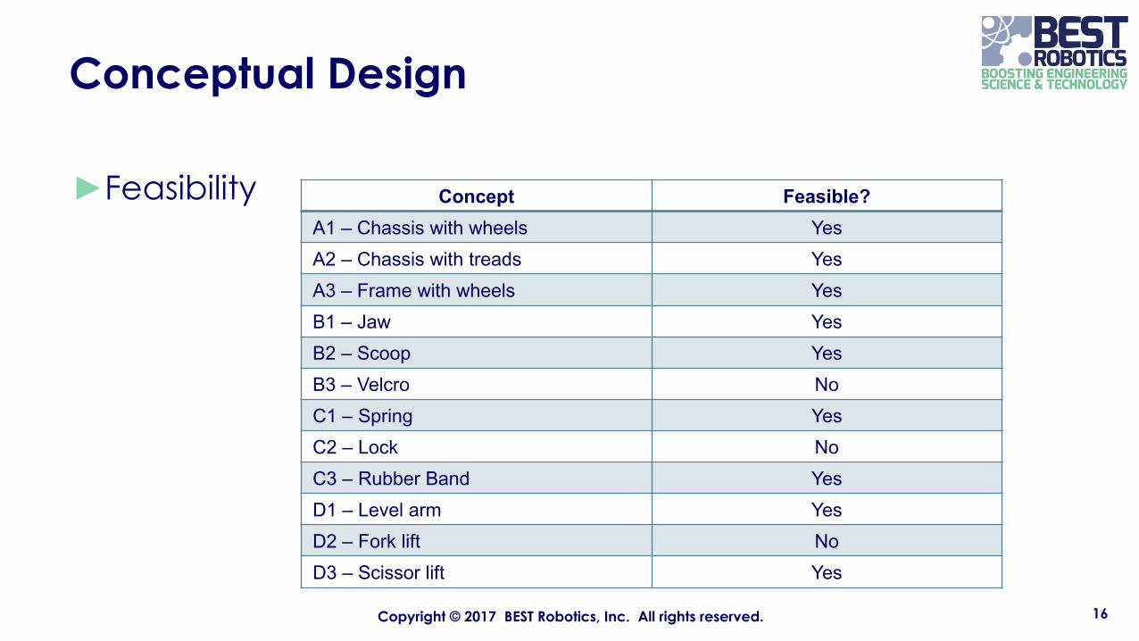
►Feasibility
16Copyright © 2017 BEST Robotics, Inc. All rights reserved.
Concept Feasible?A1 – Chassis with wheels YesA2 – Chassis with treads YesA3 – Frame with wheels YesB1 – Jaw YesB2 – Scoop YesB3 – Velcro NoC1 – Spring YesC2 – Lock NoC3 – Rubber Band YesD1 – Level arm YesD2 – Fork lift NoD3 – Scissor lift Yes

Conceptual Design
►Go – NoGo (needs only)
►And so on…..
17Copyright © 2017 BEST Robotics, Inc. All rights reserved.
Requirement A1 A2 A3Meet weight
requirements Yes Yes Yes
Meet size requirements Yes Yes Yes
Pick up game pieces Yes Yes Yes
Requirement B1 B2B3 not
feasibleMeet weight
requirements Yes Yes
Meet size requirements Yes Yes
Pick up game pieces Yes Yes
Conceptual Design
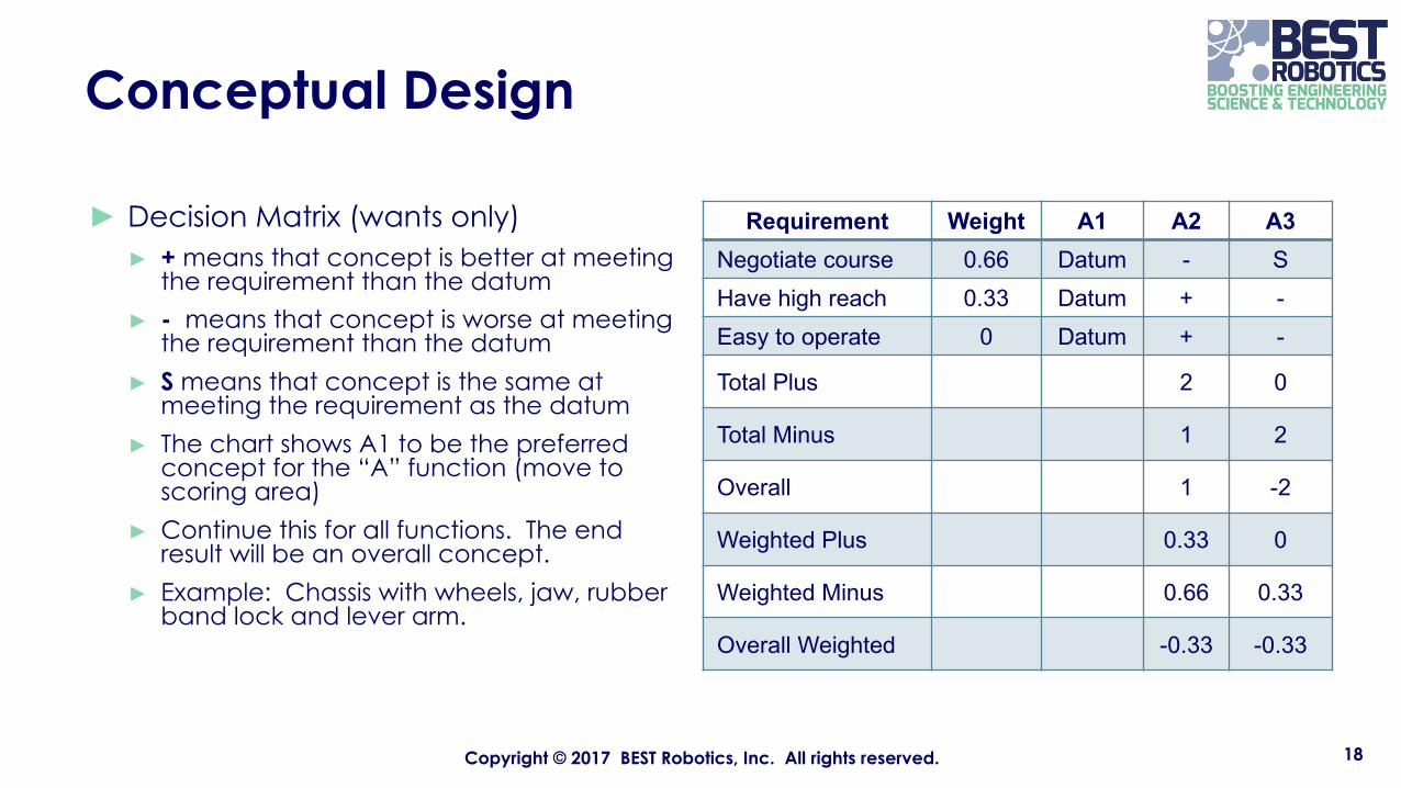
► Decision Matrix (wants only)► + means that concept is better at meeting
the requirement than the datum► - means that concept is worse at meeting
the requirement than the datum► S means that concept is the same at
meeting the requirement as the datum► The chart shows A1 to be the preferred
concept for the “A” function (move to scoring area)
► Continue this for all functions. The end result will be an overall concept.
► Example: Chassis with wheels, jaw, rubber band lock and lever arm.
18Copyright © 2017 BEST Robotics, Inc. All rights reserved.
Requirement Weight A1 A2 A3Negotiate course 0.66 Datum - SHave high reach 0.33 Datum + -Easy to operate 0 Datum + -
Total Plus 2 0
Total Minus 1 2
Overall 1 -2
Weighted Plus 0.33 0
Weighted Minus 0.66 0.33
Overall Weighted -0.33 -0.33

Preliminary Design
► STEP 1: Take the concept and sketch an overall configuration. Do not worry about the details at this point. Label the major components.
► STEP 2: Sketch each of the major components on a separate sheet. Put enough information on the sketch so that the component can be made from a piece of cardboard. Try to keep the overall size requirement in mind.
► STEP 3: Make cardboard pieces from the sketches and assemble.► STEP 4: Evaluate the model and ensure it meets all of the requirements.
Make modifications as needed. Try it on the course and ensure it fits inside the 24x24x24 inch box.
► You now have a model of the robot.
19Copyright © 2017 BEST Robotics, Inc. All rights reserved.

Detailed Design
►STEP 1: Disassemble the cardboard model and mark-up each sketch to show the final dimensions. Also indicate on the sketch the material that will be used to make the real part.
►STEP 2: Create sketches for parts that are not on the model such as wheel mounts, motor mounts, etc. Consider lifting requirements, torque available from motors, etc.
►STEP 3: Create an overall assembly sketch of all parts. Label each part.► You now have a detailed design of the robot.
►STEP 4: Fabricate each part from the sketch and assemble the robot. ► You now have a prototype robot.
20Copyright © 2017 BEST Robotics, Inc. All rights reserved.
Production Design
►STEP 1: After testing the prototype, make changes as required.
►STEP 2: Once the robot is in its final configuration, finalize detailed drawings of each part.
21Copyright © 2017 BEST Robotics, Inc. All rights reserved.
BEST Engineering Mechanics
►PURPOSE
► Introduce students to the theory of some simple machines.
►Apply the theory of simple machines to robotics design.
22Copyright © 2017 BEST Robotics, Inc. All rights reserved.
Machines
►WHAT IS A MACHINE?►A device that transmits, or changes, the application of energy.►Allows for the multiplication of force at the expense of distance. ►A machine does work.►Work is force applied through a distance.
23Copyright © 2017 BEST Robotics, Inc. All rights reserved.

Simple Machines
►Simple machines have existed and have been used for centuries.
►Each one makes work easier to do by providing some trade-off between the force applied and the distance over which the force is applied.
►We will discuss the following simple machines and relate them to robotics design:► LEVERS► PULLEYS► GEARS
►We will also discuss the concepts of torque as related to robotics design
24Copyright © 2017 BEST Robotics, Inc. All rights reserved.

Levers
►A lever is a stiff bar that rotates about a pivot point called the fulcrum.
►Depending on where the pivot point is located, a lever can multiply either the force applied or the distance over which the force is applied
25Copyright © 2017 BEST Robotics, Inc. All rights reserved.

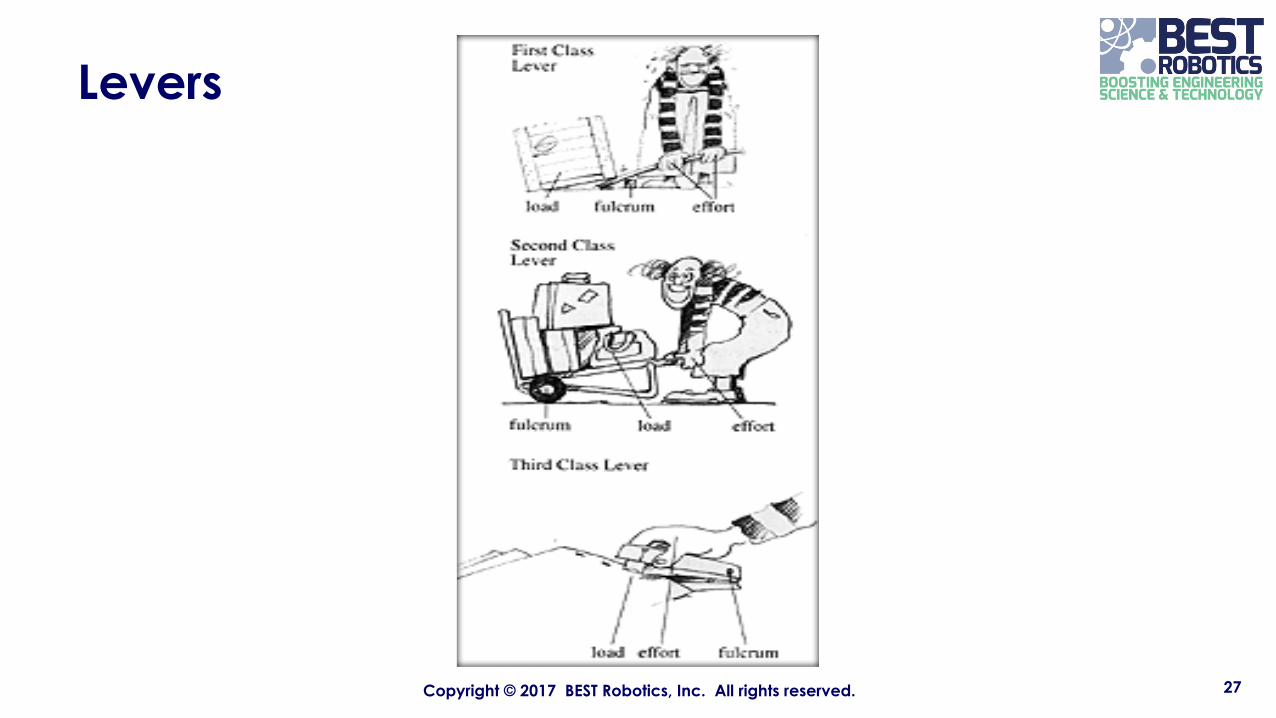
Three Classes of Levers
►First Class Levers – The fulcrum is between the effort and the load. ► A seesaw is an example of a simple first class lever. ► A pair of scissors is an example of two connected first class levers.
►Second Class Levers – The load is between the fulcrum and the effort. ► A wheelbarrow is an example of a simple second class lever. ► A nutcracker is an example of two connected second class levers.
► Third Class Levers – The effort is between the fulcrum and the load. ► A stapler or a fishing rod is an example of a simple third class lever. ► A pair of tweezers is an example of two connected third class levers.
26Copyright © 2017 BEST Robotics, Inc. All rights reserved.
Levers
27Copyright © 2017 BEST Robotics, Inc. All rights reserved.
Levers
►Force and Effort►To lift a load with the least effort:►Place the load as close to the fulcrum as possible. ►Apply the effort as far from the fulcrum as possible.
28Copyright © 2017 BEST Robotics, Inc. All rights reserved.
Levers
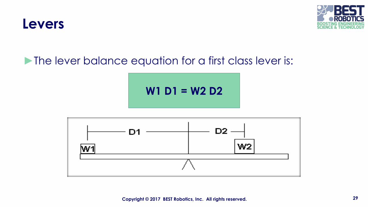
►The lever balance equation for a first class lever is:
29Copyright © 2017 BEST Robotics, Inc. All rights reserved.
W1 D1 = W2 D2
Levers
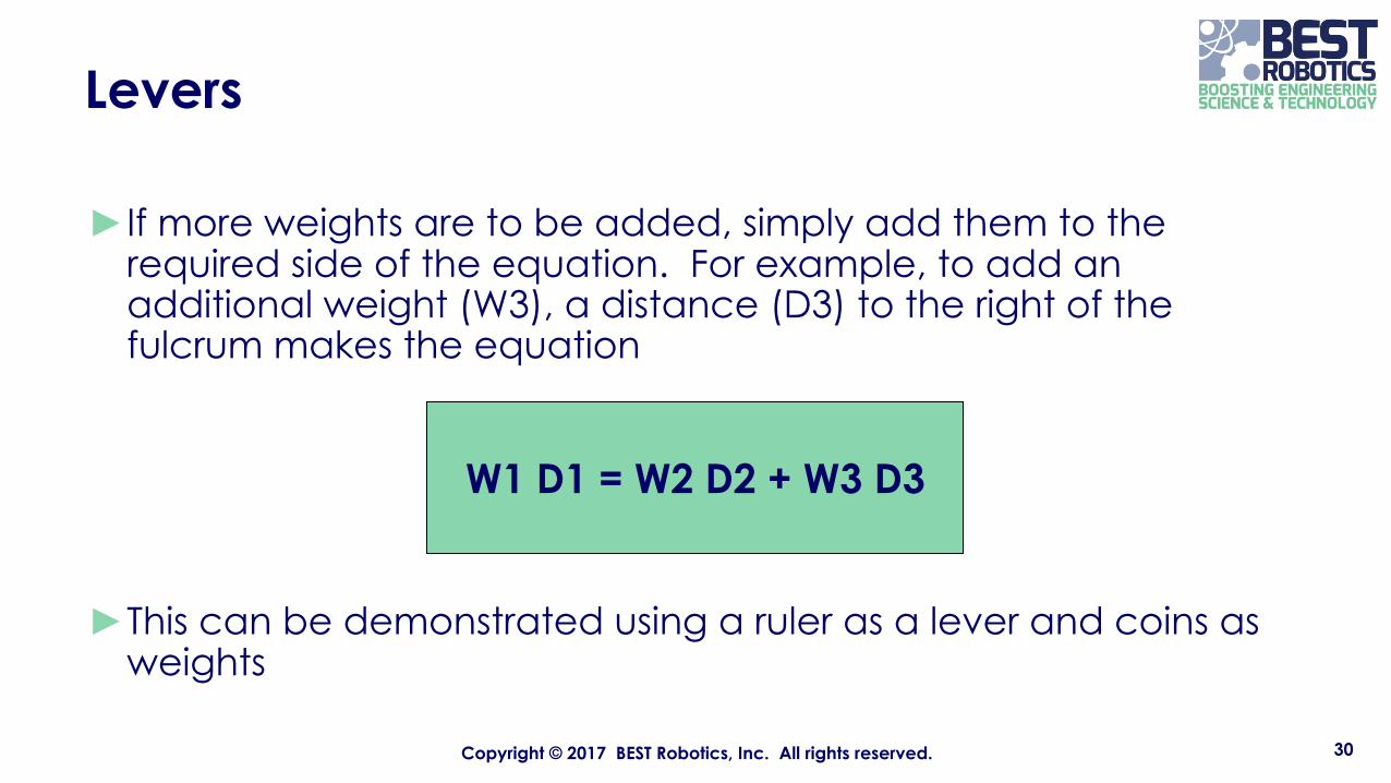
►If more weights are to be added, simply add them to the required side of the equation. For example, to add an additional weight (W3), a distance (D3) to the right of the fulcrum makes the equation
►This can be demonstrated using a ruler as a lever and coins as weights
30Copyright © 2017 BEST Robotics, Inc. All rights reserved.
W1 D1 = W2 D2 + W3 D3
Levers
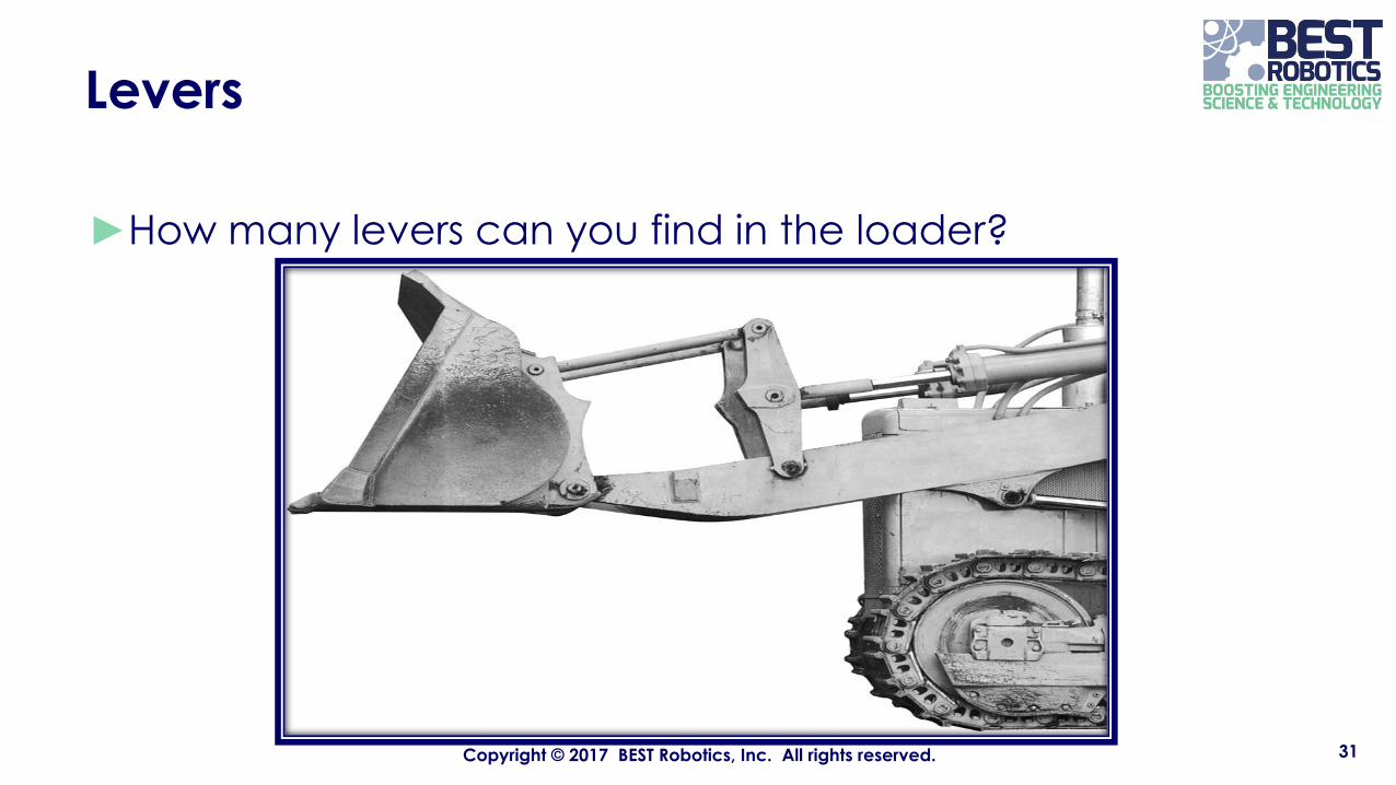
►How many levers can you find in the loader?
31Copyright © 2017 BEST Robotics, Inc. All rights reserved.
Block and Tackle
►A block and tackle is an arrangement of rope and pulleys that allows you to trade force for distance.
32Copyright © 2017 BEST Robotics, Inc. All rights reserved.
Block and Tackle
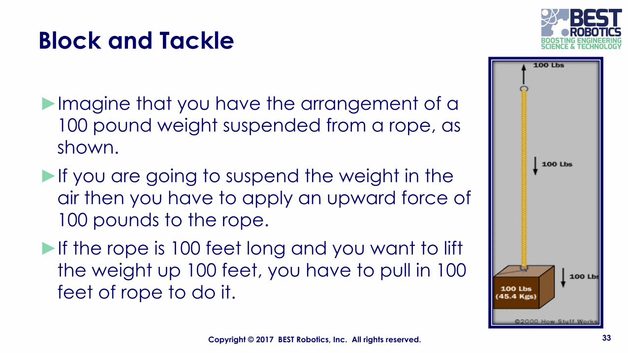
►Imagine that you have the arrangement of a 100 pound weight suspended from a rope, as shown.
►If you are going to suspend the weight in the air then you have to apply an upward force of 100 pounds to the rope.
►If the rope is 100 feet long and you want to lift the weight up 100 feet, you have to pull in 100 feet of rope to do it.
33Copyright © 2017 BEST Robotics, Inc. All rights reserved.
Block and Tackle
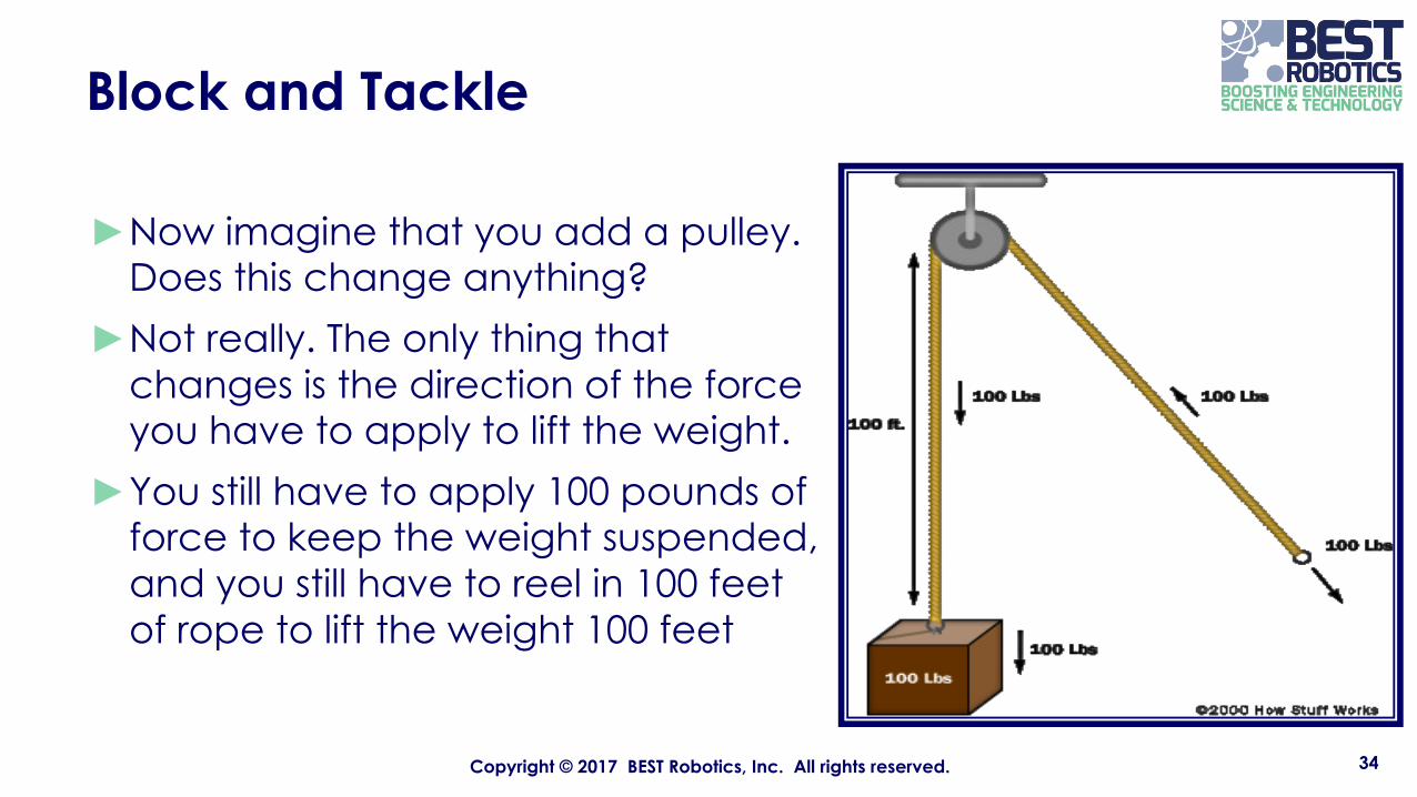
►Now imagine that you add a pulley. Does this change anything?
►Not really. The only thing that changes is the direction of the force you have to apply to lift the weight.
►You still have to apply 100 pounds of force to keep the weight suspended, and you still have to reel in 100 feet of rope to lift the weight 100 feet
34Copyright © 2017 BEST Robotics, Inc. All rights reserved.

Block and Tackle
► Now add another pulley. This actually does change things in an important way.
► You can see that the weight is now suspended by two ropes rather than one. That means the weight is split equally between the two ropes, so each one holds only half the weight, or 50 pounds.
► That means that if you want to hold the weight suspended in the air, you only have to apply 50 pounds of force (the ceiling exerts the other 50 pounds of force on the other end of the rope).
► If you want to lift the weight 100 feet higher, then you have to reel in twice as much rope -200 feet of rope must be pulled in.
► This demonstrates a force-distance tradeoff. The force has been cut in half but the distance the rope must be pulled has doubled.
35Copyright © 2017 BEST Robotics, Inc. All rights reserved.
Gears
►Gears are generally used for one of three different reasons:► To reverse the direction of rotation ► To increase or decrease the speed of rotation► To move rotational motion to a different axis
36Copyright © 2017 BEST Robotics, Inc. All rights reserved.
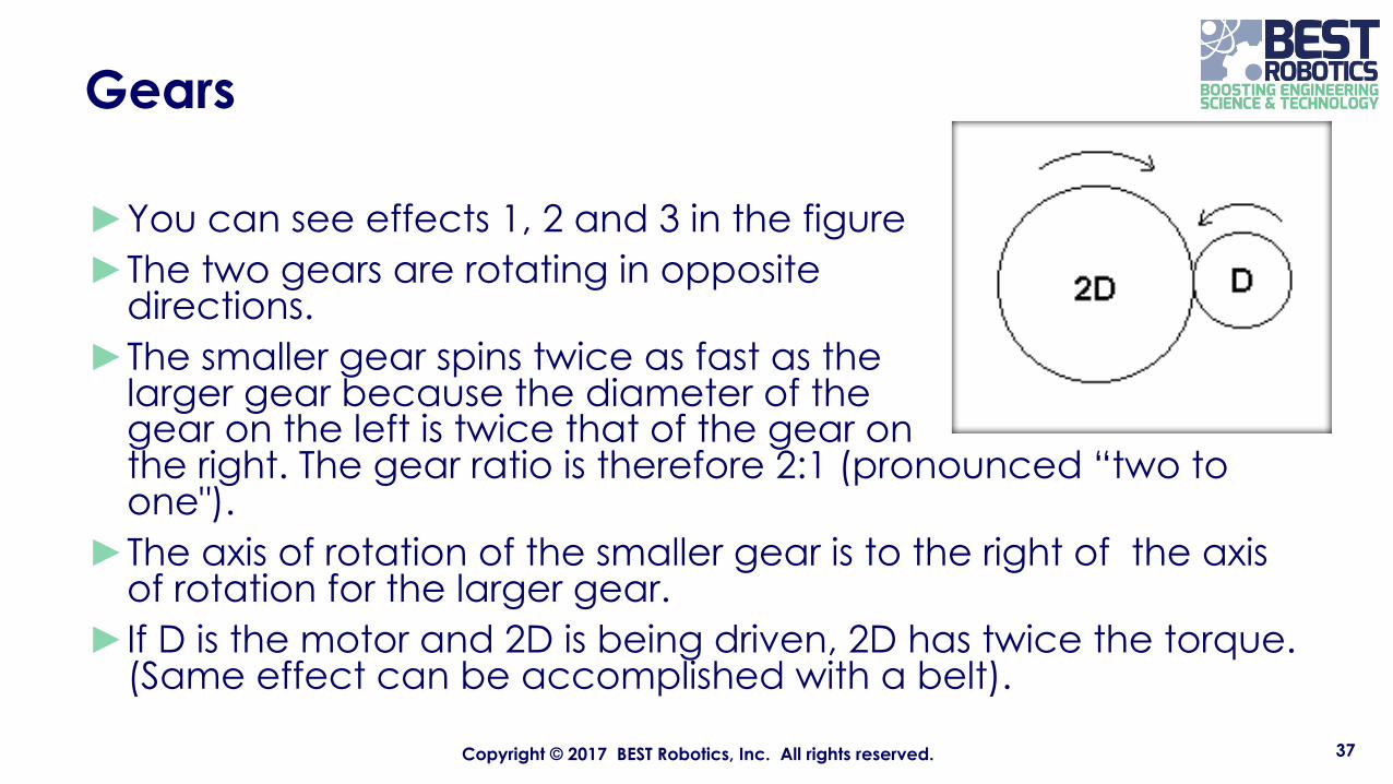
Gears
►You can see effects 1, 2 and 3 in the figure ►The two gears are rotating in opposite
directions.►The smaller gear spins twice as fast as the
larger gear because the diameter of the gear on the left is twice that of the gear on the right. The gear ratio is therefore 2:1 (pronounced “two to one").
►The axis of rotation of the smaller gear is to the right of the axis of rotation for the larger gear.
►If D is the motor and 2D is being driven, 2D has twice the torque. (Same effect can be accomplished with a belt).
37Copyright © 2017 BEST Robotics, Inc. All rights reserved.
Torque
►A force applied to a body that causes it to rotate creates torque.
►The motors supplied in your kits are designed for a specific torque and are listed as:► Large motors – 216 in-oz at 56 rpm (a little less than 1 revolution per
second)►Small motors – 34 in-oz at 113 rpm (a little less than 2 revolutions per
second)
38Copyright © 2017 BEST Robotics, Inc. All rights reserved.
Torque
►The equation for torque for the motors is:
►Where:T = torque of the motorr = radius of the motor shaft, pulley or whatever is attached to the motor shaftF = the force created by the motor
39Copyright © 2017 BEST Robotics, Inc. All rights reserved.
T = r F
Torque
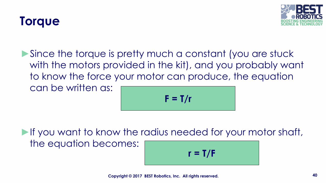
►Since the torque is pretty much a constant (you are stuck with the motors provided in the kit), and you probably want to know the force your motor can produce, the equation can be written as:
►If you want to know the radius needed for your motor shaft, the equation becomes:
40Copyright © 2017 BEST Robotics, Inc. All rights reserved.
F = T/r
r = T/F

Design Example
►Let’s take the concepts we have learned and design an arm that will lift a 1 lb game piece.
►Let’s assume that our mockup resulted in the following:
41Copyright © 2017 BEST Robotics, Inc. All rights reserved.
Design Example
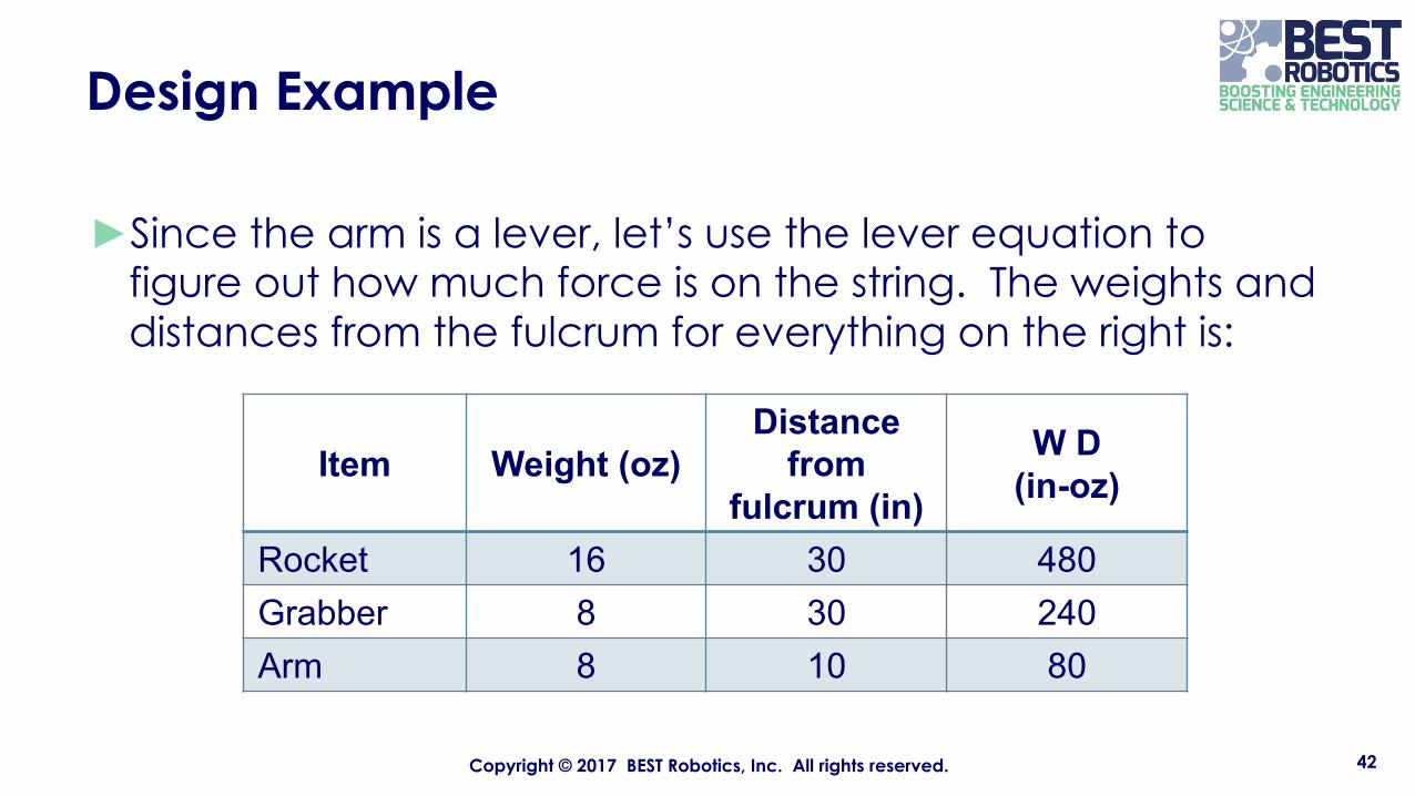
►Since the arm is a lever, let’s use the lever equation to figure out how much force is on the string. The weights and distances from the fulcrum for everything on the right is:
42Copyright © 2017 BEST Robotics, Inc. All rights reserved.
Item Weight (oz)Distance
from fulcrum (in)
W D(in-oz)
Rocket 16 30 480Grabber 8 30 240Arm 8 10 80
Design Example
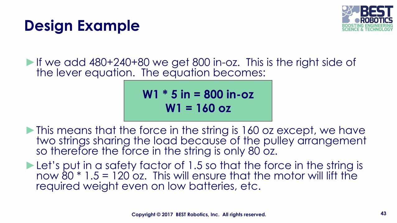
►If we add 480+240+80 we get 800 in-oz. This is the right side of the lever equation. The equation becomes:
►This means that the force in the string is 160 oz except, we have two strings sharing the load because of the pulley arrangement so therefore the force in the string is only 80 oz.
►Let’s put in a safety factor of 1.5 so that the force in the string is now 80 * 1.5 = 120 oz. This will ensure that the motor will lift the required weight even on low batteries, etc.
43Copyright © 2017 BEST Robotics, Inc. All rights reserved.
W1 * 5 in = 800 in-ozW1 = 160 oz
Design Example
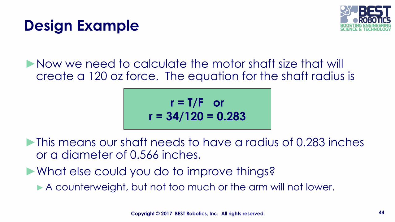
►Now we need to calculate the motor shaft size that will create a 120 oz force. The equation for the shaft radius is
►This means our shaft needs to have a radius of 0.283 inches or a diameter of 0.566 inches.
►What else could you do to improve things?►A counterweight, but not too much or the arm will not lower.
44Copyright © 2017 BEST Robotics, Inc. All rights reserved.
r = T/F or r = 34/120 = 0.283