Embed Size (px)
Citation preview

STATE GOVERNMENTOF WESTERN AUSTRALIA
Swan River Trust
Best management practices for foreshore stabilisation
Approaches and decision-support framework
December 2009
Caring for the Swan Canning Riverpark
Part A - Foreshore stabilisation policy and processes 1
1 IntroductIon
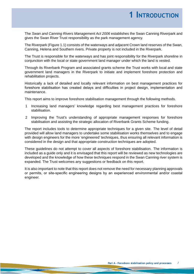
The Swan and Canning Rivers Management Act 2006 establishes the Swan Canning Riverpark and gives the Swan River Trust responsibility as the park management agency.
The Riverpark (Figure 1.1) consists of the waterways and adjacent Crown land reserves of the Swan, Canning, Helena and Southern rivers. Private property is not included in the Riverpark.
The Trust is responsible for the waterways and has joint responsibility for the Riverpark shoreline in conjunction with the local or state government land manager under which the land is vested.
Through its Riverbank Program and associated grants scheme the Trust works with local and state government land managers in the Riverpark to initiate and implement foreshore protection and rehabilitation projects.
Historically a lack of detailed and locally relevant information on best management practices for foreshore stabilisation has created delays and difficulties in project design, implementation and maintenance.
This report aims to improve foreshore stabilisation management through the following methods.
Increasing land managers’ knowledge regarding best management practices for foreshore 1 stabilisation.
Improving the Trust’s understanding of appropriate management responses for foreshore 2 stabilisation and assisting the strategic allocation of Riverbank Grants Scheme funding.
The report includes tools to determine appropriate techniques for a given site. The level of detail provided will allow land managers to undertake some stabilisation works themselves and to engage with design engineers for the more ‘engineered’ techniques, thus ensuring all relevant information is considered in the design and that appropriate construction techniques are adopted.
These guidelines do not attempt to cover all aspects of foreshore stabilisation. The information is included as a guide only and it is envisaged that this report will be reviewed as new technologies are developed and the knowledge of how these techniques respond in the Swan Canning river system is expanded. The Trust welcomes any suggestions or feedback on this report.
It is also important to note that this report does not remove the need for necessary planning approvals or permits, or site-specific engineering designs by an experienced environmental and/or coastal engineer.

Part A - Foreshore stabilisation policy and processes 2
Figure 1.1 Swan River Trust River Reserve, Development Control Area and Riverpark boundary

Part A - Foreshore stabilisation policy and processes 3
1.1 Background
Information on the present state of the foreshores and active processes was collected as part of a comprehensive foreshore assessment project, initiated by the Trust in 2002, for the Swan, Canning, Helena and Southern rivers. Specific information was collected on shoreline processes, shoreline character, condition of foreshore retaining structures and vegetation type and condition. This information was presented in the Swan and Canning Rivers Foreshore Assessment and Management Strategy (Swan River Trust 2008) with further detailed information contained in Damara (2007), Oceanica et al. (2007) and the geodatabase held by the Trust. The foreshore condition and active processes were summarised in the foreshore strategy along with recommendations for management and investment (Swan River Trust 2008). The data collected for the foreshore assessment project is available on DVD. The information on erosion, inundation and problems related to foreshore stability has been included here for consideration when identifying applicable foreshore stabilisation techniques.
1.1.1 Erosion, inundation, climate change and foreshore stability
Rivers and estuaries are constantly changing their form in response to natural geomorphic processes, shifts in natural conditions in the surrounding catchment, and human impacts. The foreshore is a dynamic boundary that responds to relative movements of land and water. The dynamic nature of foreshore migration and inundation is typically only of concern when there is something of value immediately adjacent that is threatened by erosion or inundation.
As human activities and infrastructure are generally in the ‘dry’ part of the profile, landward movement of the foreshore typically has the most significant impact on human amenity. Offshore movement of the foreshore (e.g. accretion) generally has a more limited effect on amenity for the majority of foreshore activities. However, accretion may smother riparian vegetation or benthic habitats. Sedimentation of riverine reaches can also affect navigation and results in increased channel migration and inundation.
A range of external forces, including erosion and inundation processes, as well as the potential effects of climate change, operate on Swan Canning river system foreshores. The type and magnitude of the governing processes, and the foreshore characteristics (e.g. vegetation coverage, foreshore elevation), can result in net erosion or accretion of the foreshore, inundation of the foreshore, or sedimentation of the channel.
Foreshore erosion
A range of erosion mechanisms may be active in an estuarine environment.
Energetic wave conditions — often associated with quite dramatic loss on beaches during single • storm events.
Increased mean water level — causes an upwards migration of the active hydraulic zone.•
Decreased mean water level — causes a downwards migration of the active hydraulic zone.•
Vegetation loss — tends to provide a bank that is less resistant to hydraulic action.•
Sediment sink/sources — locations experience net erosion or accretion where there is an • imbalance of sediment transport.
Sediment deficit — change that alters the prevailing sediment transport conditions, removing a • quantity of sediment from active forces before normal transport patterns return.
Strong currents — located principally where there are restrictions in cross-sectional area.•
Seasonality — the intensity of prevailing conditions and their persistence may affect the net • sediment transport rate.

Part A - Foreshore stabilisation policy and processes 4
Drainage structures — erosion associated with drainage outfalls may extend beyond the immediate • vicinity of the flow path.
Flow over banks — erosion, often gully erosion, associated with water flowing directly over the • banks due to overtopped water draining or as a result of stormwater runoff.
Sedimentation — decreases the channel cross-sectional area, thereby increasing the potential • for channel planform migration and inundation through flooding.
Trampling — loss of vegetation and sediment can occur due to uncontrolled access, worm digging, • boat launching and animal trampling.
Foreshore erosion is generally associated with energetic conditions. However, low-energy conditions may also occasionally create foreshore retreat.
Inundation
Foreshore inundation occurs when water levels and waves are high enough to flood normally dry land. This can impact on foreshore vegetation or structures and curtails amenity. In the estuarine reaches, the inundation level is determined largely by the summation of tides, surges and wave excursion over land. Wave action is strongly influenced by the profile grade and the permeability of the surface over which waves run. In the fluvial reaches, the inundation level is dependent on topography and flood levels.
For estuarine beaches in the Swan River, formation of a seasonal tidal berm (accretionary ridge) typically occurs around +0.5m Australian Height Datum (AHD). This is typically below the annual maximum water levels. Under high water-level events, waves will tend to wash over the beach, percolating through the sand and dissipating the wave energy.
Although engineered mitigation structures are generally higher than beaches, they have low permeability, allowing waves to run up further. Drainage of the overtopping water places considerable stress on the protective structures. For areas of flat land behind walling, waves may travel relatively long distances before dissipating.
In the estuarine reaches, inundation effects vary significantly depending on the degree of wave exposure and the joint probability of surge and wave directions. Generally, west-facing shores experience the greatest inundation, as westerlies are associated with positive oceanic surge and are most severe during winter, when mean water levels are high.
Inundation of the banks in the upper reaches of the Swan Canning river system results in increased activity of the floodplain. Although flooding can damage infrastructure, the over-bank processes are beneficial as sediment deposition can regenerate banks in some areas. Many floodplains contain secondary channels or gullies to drain the floodwaters back into the channel. Low-lying regions where rivers and creeks converge are most susceptible to inundation by floodwaters.
Climate change
Climate change is an important consideration in the management of foreshores and design of erosion control/restoration works.
Climate change is evident as an influence on the Swan Canning river system and has already produced irreversible change. The rate of change is increasing relative to the past century and changes to the familiar river regime will become increasingly evident as the century progresses. Tidal and non-tidal sections of the rivers will be altered by significantly diminished stream-flow with warming of the water bodies and surrounding environment. There will be changes in the seasonal timing of flows with smaller and later autumn/winter flows. Tidal reaches will also be affected by sea level rise and by superimposed storm surges (Swan River Trust 2007).
Additional information can be found in the report Potential Impacts of Climate Change on the Swan and Canning rivers (Swan River Trust 2007) located on the Trust’s website <www.swanrivertrust.wa.gov.au>.
Part A - Foreshore stabilisation policy and processes 5
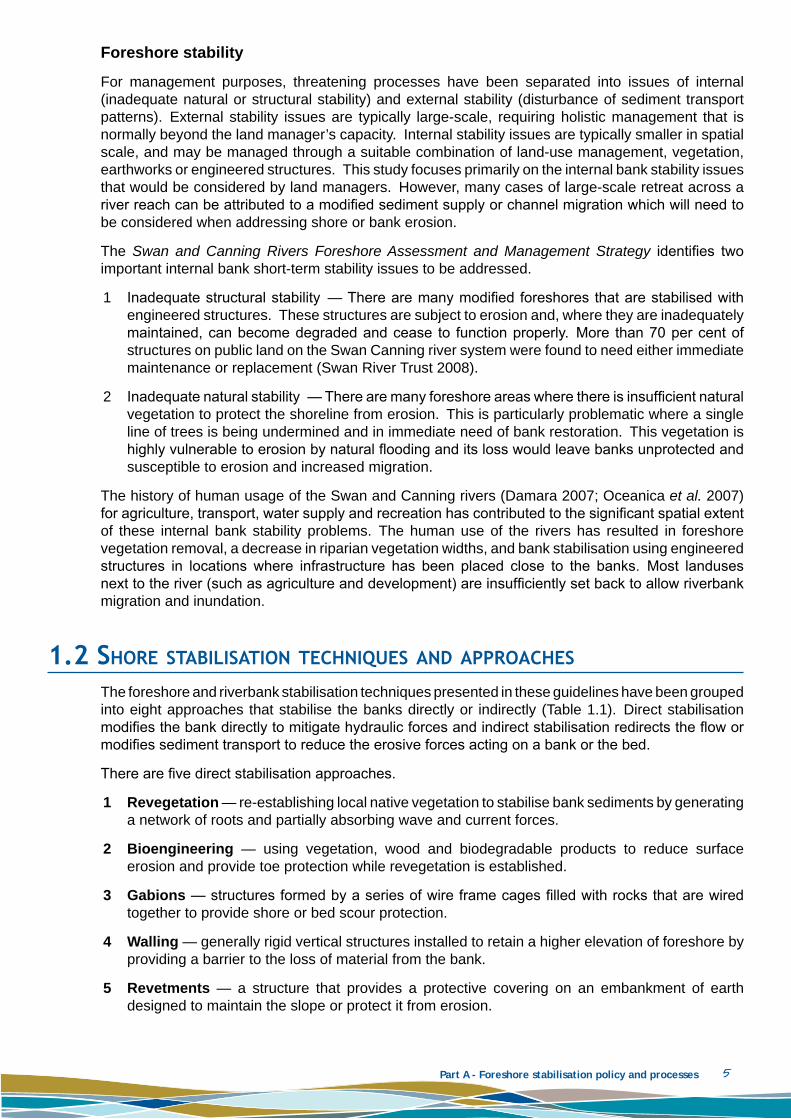
Foreshore stability
For management purposes, threatening processes have been separated into issues of internal (inadequate natural or structural stability) and external stability (disturbance of sediment transport patterns). External stability issues are typically large-scale, requiring holistic management that is normally beyond the land manager’s capacity. Internal stability issues are typically smaller in spatial scale, and may be managed through a suitable combination of land-use management, vegetation, earthworks or engineered structures. This study focuses primarily on the internal bank stability issues that would be considered by land managers. However, many cases of large-scale retreat across a river reach can be attributed to a modified sediment supply or channel migration which will need to be considered when addressing shore or bank erosion.
The Swan and Canning Rivers Foreshore Assessment and Management Strategy identifies two important internal bank short-term stability issues to be addressed.
Inadequate structural stability — There are many modified foreshores that are stabilised with 1 engineered structures. These structures are subject to erosion and, where they are inadequately maintained, can become degraded and cease to function properly. More than 70 per cent of structures on public land on the Swan Canning river system were found to need either immediate maintenance or replacement (Swan River Trust 2008).
Inadequate natural stability — There are many foreshore areas where there is insufficient natural 2 vegetation to protect the shoreline from erosion. This is particularly problematic where a single line of trees is being undermined and in immediate need of bank restoration. This vegetation is highly vulnerable to erosion by natural flooding and its loss would leave banks unprotected and susceptible to erosion and increased migration.
The history of human usage of the Swan and Canning rivers (Damara 2007; Oceanica et al. 2007) for agriculture, transport, water supply and recreation has contributed to the significant spatial extent of these internal bank stability problems. The human use of the rivers has resulted in foreshore vegetation removal, a decrease in riparian vegetation widths, and bank stabilisation using engineered structures in locations where infrastructure has been placed close to the banks. Most landuses next to the river (such as agriculture and development) are insufficiently set back to allow riverbank migration and inundation.
1.2 Shore StaBIlISatIon technIqueS and approacheS
The foreshore and riverbank stabilisation techniques presented in these guidelines have been grouped into eight approaches that stabilise the banks directly or indirectly (Table 1.1). Direct stabilisation modifies the bank directly to mitigate hydraulic forces and indirect stabilisation redirects the flow or modifies sediment transport to reduce the erosive forces acting on a bank or the bed.
There are five direct stabilisation approaches.
Revegetation1 — re-establishing local native vegetation to stabilise bank sediments by generating a network of roots and partially absorbing wave and current forces.
Bioengineering2 — using vegetation, wood and biodegradable products to reduce surface erosion and provide toe protection while revegetation is established.
Gabions3 — structures formed by a series of wire frame cages filled with rocks that are wired together to provide shore or bed scour protection.
Walling4 — generally rigid vertical structures installed to retain a higher elevation of foreshore by providing a barrier to the loss of material from the bank.
Revetments5 — a structure that provides a protective covering on an embankment of earth designed to maintain the slope or protect it from erosion.

Part A - Foreshore stabilisation policy and processes 6
Three indirect stabilisation approaches are considered.
Renourishment1 — replacing foreshore sediment (usually sand) lost through longshore drift or erosion.
Groynes/headlands2 — constructing narrow structures perpendicular to the shore (with renourishment) that reduce alongshore sediment transport, capturing sediment on the updrift side of the structure.
Flow modification3 — modifying the bed (riffles or sediment extraction) or lower bank (baffles/spurs, large woody debris) to deflect/dissipate erosive currents and encourage sediment deposition.
Table 1.1 Shore stabilisation approaches and techniques
DIRECT APPROACHES TECHnIqUES InDIRECT
APPROACHES TECHnIqUES
Revegetation
Sedges
Renourishment
Without associated structures
Trees and shrubs Combined with hard structures
Ground covers With sacrificial/temporary structures
Bioengineering (with revegetation)
Coir logs Constructing secondary features
Jute matting
Groynes/ headlands
Single short groyne
Brushing/bundling Single long groyne
Soil replacement (gravel/sand mix)
Headland field
Short groyne field
Brush mattressing Long groyne field
GabionsBaskets (stepped)
Geotextile
Flow modification
Riffles
Mattress Flow baffles
Walling
Baffles Channel excavation
Log walling River training
Sand bag walls Spurs
Limestone block (gravity) Large woody debris
Piled walls
Concrete panel
Sheet-piling
Revetments
Rock toe with resloping
Sand bag
Geotextile
Tipped rock
Interlocked rock
Layered
Cellular system
Block revetment
Flexmat

Part A - Foreshore stabilisation policy and processes 7
References on all of the techniques listed in Table 1.1 are provided in Appendix A. The information in many of these references should be read with caution as the majority are written for rivers dominated by stronger currents, and open coasts dominated by larger waves, than for conditions experienced in the Swan Canning river system.
Detailed information for eight specific direct techniques is included in Part B:
revegetation1
coir logs2
brush mattressing3
gabions4
log walling5
cut limestone block walling6
rock revetments7
geotextile revetments.8
Indirect techniques are detailed in Part C (to be published early 2010). Additional chapters may also be added to this report to provide more detailed local information on these other techniques.
The majority of techniques listed in Table 1.1 require design by a suitably experienced coastal engineer or suitably qualified expert. However, the initial project scope can be prepared based on the information included in this document.
Managed retreat
Managed retreat should be considered as an alternative option early in the planning process. Managed retreat permits bank erosion to continue, while managing any safety or environmental concerns. It can reduce downdrift erosion and allow the river to migrate. This is often the least expensive approach, with the least adverse environmental impacts; however, requires enough space to allow the river to migrate.
Managed retreat is likely to require fencing, signage and relocation of any infrastructure at risk of damage. Revegetation of surrounding stable areas and management of sediment should also be considered to protect and enhance ecological function.
1.3 reportIng Structure
These best management practice guidelines are intended to provide the following information.
When stabilisation is required (Section 3.1).•
If a new technique should be considered rather than maintaining the vegetation/structure present • (Section 3.1).
What techniques might be appropriate at the site (Section 3.2).•
Elements to be included in design/construction plans (Parts B and C).•
Methods to design and implement revegetation and some bioengineering techniques (Part B – • Section 2, 3 and 4). Enough detail has been included on these techniques for land managers to design the stabilisation projects. However, an experienced coastal engineer and Trust officers should always be consulted before implementing any new stabilisation technique on the foreshore.
Maps of the Swan Canning river system providing a preliminary indication of the minimum level of • stabilisation based on foreshore conditions and values in 2006–07 (Section 6). This investigation

Part A - Foreshore stabilisation policy and processes 8
was conducted on a wide spatial scale and detailed site surveys are still required before any shore stabilisation techniques are selected. The resolution is not sufficient to identify the needs of smaller sites or for emergency works.
These guidelines are also intended to provide the Trust with information to:
determine if a proposed application for Riverbank is appropriate for the site•
strategically allocate Trust funding for stabilisation works•
establish trial stabilisation projects to review techniques for inclusion in any expanded versions • of this BMP report
improve its ability to review Riverbank applications•
expedite the approval process for stabilisation works by providing guidelines to land managers • and consultants before they start the design process.
This report does not remove the need for site-specific engineering designs and is intended to provide guidance when seeking input from experienced environmental and/or coastal engineers.

Part A - Foreshore stabilisation policy and processes 9
2 legISlatIon and polIcy Framework
2.1 legISlatIon and polIcy context
Legislation, policies and strategies related to foreshore planning are summarised in Table 2.1. These policies should be consulted where applicable for any foreshore stabilisation project.
Table 2.1 Key legislation, policies, strategies and guidelines relating to foreshore management
Source: modified from EMRC (2007)
LEgISLATIOn DESCRIPTIOnSwan and Canning Rivers Management Act (2006) and
Swan and Canning Rivers Management Regulations (2007)
The principal Act for the management of the Swan and Canning rivers, replacing the Swan River Trust Act (1988)
The Act defines the Swan River Trust Development Control Area (Figure 1.1). Part 5 of the Act outlines planning approval requirements for development on a lot located wholly in the DCA. Although the Trust is responsible for assessment and preparation of a recommendation, on such applications final determination is issued by the Minister for Environment
Establishes the Swan Canning Riverpark (Figure 1.1). The Riverpark consists of the waterways and adjacent public land of the Swan, Canning, Helena and Southern rivers
More detailed maps showing the Development Control Area and Riverpark can be found at the Trust website <www.swanrivertrust.wa.gov.au>
Under this legislation, the Trust has joint responsibility for the Riverpark foreshore in conjunction with the local or state government agency vested with management responsibility for the land
The pending River Protection Strategy and the policies and regulations of the Trust are intended to guide land managers towards appropriate landuse and development in reserves
The Swan and Canning Rivers Management Regulations (2007) came into effect with the Act. The regulations classify certain types of development/activities that are excluded from the planning approval requirements of Part 5 of the Act and identify those that will require issue of a permit by the Trust
The regulations also established separate permit requirements for other non-development-related activities that may cause river bank collapse or movement, riverbed disturbance or vegetation damage
Aboriginal Heritage Act (1972), Aboriginal Heritage Regulations (1974) and Native Title Act(1993)
When planning a foreshore rehabilitation project, the following departments must be contacted
Department of Indigenous Affairs to identify any registered sites and • obtain advice on necessary approvals for rehabilitation works
Department of Land Information to determine if the project area is • subject to a native title claim. The national native Title Tribunal and the Office of native Title of the Department of the Premier and Cabinet can be contacted to seek an opinion about the likely impact of the project on the provisions of the Native Title Act (1993)
Conservation and Land Management Act (1984)
Establishes a comprehensive set of legislative provisions dealing with state conservation and land management matters
Part A - Foreshore stabilisation policy and processes 10
Environmental Protection Act 1986 and Environmental Protection (Clearing of native Vegetation) Regulations 2004
Provides for the establishment of the Environmental Protection Authority as a statutory authority as the primary provider of independent environmental advice to government
Provides for the prevention, control and abatement of pollution and environmental harm, for the conservation, preservation, protection, enhancement and management of the environment
The Environmental Protection Act 1986 and Environmental Protection (Clearing of native Vegetation) Regulations 2004 contain provisions that protect native vegetation while allowing for approved clearing activities. Refer to DEC website for further information <http://www.dec.wa.gov.au/management-and-protection/native-vegetation/legislation.html>
Planning and Development Act (2005)
Integrates the Western Australian Planning Commission Act (1985), the Metropolitan Region Town Planning Scheme Act (1959) and the Town Planning and Development Act (1928)
Waterways Conservation Act (1976)
Makes provision for the conservation and management of certain waters and associated land and environment
Wildlife Conservation Act 1950
Provides for the conservation and protection of wildlife
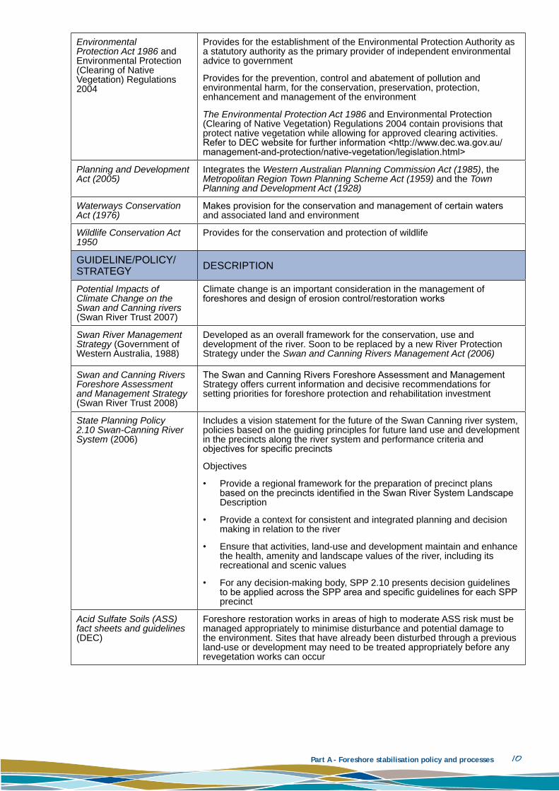
GUIDELInE/POLICy/STRATEgy DESCRIPTIOn
Potential Impacts of Climate Change on the Swan and Canning rivers (Swan River Trust 2007)
Climate change is an important consideration in the management of foreshores and design of erosion control/restoration works
Swan River Management Strategy (Government of Western Australia, 1988)
Developed as an overall framework for the conservation, use and development of the river. Soon to be replaced by a new River Protection Strategy under the Swan and Canning Rivers Management Act (2006)
Swan and Canning Rivers Foreshore Assessment and Management Strategy (Swan River Trust 2008)
The Swan and Canning Rivers Foreshore Assessment and Management Strategy offers current information and decisive recommendations for setting priorities for foreshore protection and rehabilitation investment
State Planning Policy 2.10 Swan-Canning River System (2006)
Includes a vision statement for the future of the Swan Canning river system, policies based on the guiding principles for future land use and development in the precincts along the river system and performance criteria and objectives for specific precincts
Objectives
Provide a regional framework for the preparation of precinct plans • based on the precincts identified in the Swan River System Landscape Description
Provide a context for consistent and integrated planning and decision • making in relation to the river
Ensure that activities, land-use and development maintain and enhance • the health, amenity and landscape values of the river, including its recreational and scenic values
For any decision-making body, SPP 2.10 presents decision guidelines • to be applied across the SPP area and specific guidelines for each SPP precinct
Acid Sulfate Soils (ASS) fact sheets and guidelines (DEC)
Foreshore restoration works in areas of high to moderate ASS risk must be managed appropriately to minimise disturbance and potential damage to the environment. Sites that have already been disturbed through a previous land-use or development may need to be treated appropriately before any revegetation works can occur

Part A - Foreshore stabilisation policy and processes 11
Statement of Planning Policy No 2.8 Bushland Policy for the Perth Metropolitan Region and Bush Forever
The aim of this policy is to provide a statutory policy and implementation framework that will ensure bushland protection and management issues in the Perth Metropolitan Region are addressed appropriately
This policy recognises the protection and management of significant bushland areas that have been identified for protection through an endorsed strategy, as a fundamental consideration in the planning process, while also seeking to integrate and balance wider environmental, social and economic considerations, thereby reflecting the principles of sustainability
Bush Forever identifies regionally significant bushland to be retained and protected forever. Following guidelines set by the World Conservation Union, Bush Forever aims to protect a target figure of at least 10 per cent of the 26 original vegetation complexes in the Swan Coastal Plain portion of metropolitan Perth, and to conserve threatened ecological communities
Perth Biodiversity Project Guidelines
Local government biodiversity planning guidelines for the Perth metropolitan region have been prepared by the Perth Biodiveristy Project to assist local government to plan strategically for the retention, protection and management of Perth’s biodiversity
Foreshore Management, Policy & Guidelines for Local Government (EMRC 2007)
The policy and guidelines apply to foreshore planning and management activities undertaken by local government including development, providing native vegetation buffers, and protecting and rehabilitating foreshores. The policy primarily applies to areas comprising the foreshores of the Swan and Canning rivers and associated estuaries, streams and tributaries
Statement of Planning Policy 2.9 Water Resources
Informs key stakeholders, including local government, of their planning responsibilities in relation to protecting water resources including waterways
The State Waterways Initiative (DOW 2008)
The Department of Water has developed the State Waterways Initiative as a strategic plan for waterways management to 2011. The initiative includes actions for improving waterways planning and management, identifying priorities for waterways management, supporting measures to protect environmentally significant waterways and supporting waterway restoration
Water and Rivers Commission Foreshore Policy 1 — Identifying the foreshore area (2002)
Sets out a process for determining appropriate foreshore areas (or waterway buffers) based on biophysical criteria
2.2 Swan rIver truSt polIcyTrust policies provide the basis for decision-making on land management and development in the Trust Development Control Area. These policies are intended to guide local government, State government, consultants and developers toward appropriate land-use and development.
The Trust policies relevant to foreshore stabilisation works are outlined in Table 2.2. Further Trust policies that may also be relevant to foreshore stabilisation, are listed in Table 2.3. These policies are located on the Trust website <www.swanrivertrust.wa.gov.au> and may be updated or added to.

Part A - Foreshore stabilisation policy and processes 12
Table 2.2 Trust policies with relevance to foreshore stabilisation works
POLICy nAME DESCRIPTIOn/OBjECTIvES
SRT/EA1Conservation, land use and landscape preservation
Ensure that landuse and development on and adjacent to the river system maintains and enhances the quality and amenity of the river environment
Protect the river environment through the conservation of biodiversity and ecological systems including native vegetation and habitats for plants and animals
Assist in the protection and restoration of the waterways, associated water bodies and the marine environment
Encourage a range of recreation and tourism opportunities and facilities that reflect and complement the natural and built environment of the river
SRT/EA2 Foreshore reserves
Ensure that environmentally sensitive areas adjacent to the river are adequately managed for their preservation
Provide for appropriate public access to the river and along the foreshore
Ensure that foreshores are appropriately zoned and acquired
Ensure that there is a buffer between private land and the river
SRT/EA3 Flood prone land
Ensure development does not impact on major flooding of the Swan and Canning rivers
Minimise river pollution during flood events
Ensure that development is adequately protected from damage by major flood flows
Ensure applicants are aware of flooding issues when contemplating development on the flood plain
SRT/DE1 Dredging
Ensure that dredging is necessary and, if so, does not have any detrimental impacts on the river system
Ensure that dredging activities are managed in accordance with Department of Environment and Conservation and Swan River Trust guidelines
SRT/DE7 River retaining walls
The Trust considers the construction of retaining walls as a last resort for riverbank protection, renourishment of beaches and revegetation are preferred strategies
SRT/DE19
Miscellaneous structures (groynes)
Minimise environmental impacts of new structures in the management area
Preserve the visual integrity of the river landscape
Maintain the natural flows and currents of the river
Reinforce habitat values of the river environment
SRT/E5 Heritage
Ensure that developments and landuses are in harmony with natural and cultural heritage values
Ensure that aspects of the past that have played an important role in the history of a locality are recognised (e.g. a site, building, structure, natural feature, formation or landscape) and protected for future generations to enjoy
Encourage proponents of development to recognise the historical and mythological significance of the Swan Canning river system to Aboriginal people
Preserve the integrity of the Swan Canning river system

Part A - Foreshore stabilisation policy and processes 13
Table 2.3 Other Trust policies that may also be relevant to foreshore restoration works
POLICy nAMESRT/DE6 Dewatering
SRT/DE15 yacht Club with slipways, boat pens, water lease and jetty licence
SRT/DE18 Signage
SRT/DE23 Launching ramps and slipways
SRT/DE24 Slipping facilities
SRT/D2 Access pathways and cycle access
SRT/D3 Development setback requirements
SRT/D8 Aquatic clubs
SRT/D21 jetty structures within the Swan River Trust Management Area
SRT/D25 Boardwalks
2.3 Swan rIver truSt approvalS proceSS
Assessing planning and development proposals along the Swan and Canning rivers is a core function of the Swan River Trust. Generally, Trust approval will be required where development is proposed in the Development Control Area (Figure 1.1) and the proposed works constitute development under the Swan and Canning Rivers Management Act 2006. Part 5 of the Act outlines planning approval requirements for development on a lot located wholly in the Development Control Area. Although the Trust is responsible for the assessment and preparation of a recommendation, on such applications final determination is issued by the Minister for Environment. For proposals on land partly in the Development Control Area, the decision-making authority is the Western Australian Planning Commission with advice from the Trust. Where land abuts the Development Control Area, the decision-making body is the local government authority with advice from the Trust. Should the local government authority disagree with the Trust, the matter is to be forwarded to the Western Australian Planning Commission for determination.
The Trust administers three different streams of planning applications under the Swan and Canning Rivers Management Act:
Development – Part 5 – • Swan and Canning Rivers Management Act 2006
Licences – Section 32 – • Swan and Canning Rivers Management Act 2006
Permits – Part 4 –• Swan and Canning Rivers Management Regulations 2007
From the Trust website (www.swanrivertrust.wa.gov.au) applicants can identify the relevant category under which to apply, and download the appropriate guidelines and application forms. An online document is also available detailing development control procedures and explaining the Trust’s planning applications processes.
It is also recommended that applicants read the Trust’s policy pages for information relevant to their proposed development, works, acts or activities. Details of many of the relevant policies are noted in Section 2.2.
Depending on their scale and nature, foreshore stabilisation works can often (but not always) be approved through the Trust permit application stream.
The Form 7 Application for a Permit must be completed in full, including the landowner’s consent, and accompanied by sufficient information and documentation. Failure to comply with this requirement will result in the application being returned with a request to complete the application and/or supply further information.

Part A - Foreshore stabilisation policy and processes 14
The following information should be supplied as appropriate to the works, act or activity that is subject to the permit application.
A detailed written description of the works, act or activity proposed to be authorised. Plans should • accompany the permit application if the works involve building a structure, excavating, infilling, retaining, or any other engineering to the natural landform.
A map of the area proposed for the works, act or activity.•
A copy of relevant authorisations, evidence of public liability insurance and any risk management • plans for the works, act or activity.
A description of waste disposal methods to be used.•
Evidence of any other approvals/licences obtained for the works, act or activity. •
The Trust will assess all valid Swan River Trust Form 7 permit applications located in the Swan Canning Riverpark or Development Control Area under regulation 28 of the regulations. The Trust will consider the permit application in accordance with the requirements of the Swan and Canning Rivers Management Regulations 2007, Trust policy requirements and any other appropriate environmental strategic documents.

Part A - Foreshore stabilisation policy and processes 15
3 decISIon Support Framework
A decision support framework has been developed to assist land managers to identify appropriate foreshore stabilisation works. The framework provides information to ensure that specialist advice for stabilisation is targeted and cost-effective. Firstly, land managers can follow the approach in Section 3.1 to determine if a new stabilisation technique is required for an eroding bank/foreshore, rather than maintenance of previous stabilisation efforts. If a new technique is required, the decision support framework provided in an attached spreadsheet (DSF.xls) can be used to refine which techniques should be investigated in further detail by an experienced environmental and/or coastal engineer. This framework is not exhaustive and the potential techniques should be assessed and reviewed with regard to local context (including aesthetics, alternate functions of the works and adjacent landuses).
3.1 SIte/Structure aSSeSSment
3.1.1 Dynamic foreshores
Foreshore erosion and accretion are natural processes in a dynamic river/estuary system. Erosion of one bank and accretion of the opposite bank may be a result of natural stream migration. Severe storms and elevated water levels may temporarily erode material from estuarine beaches. This sediment may be transported offshore and subsequently moved back to the beach by prevailing wind waves.
Foreshore erosion may also be caused by human activities; for example, boat wash and pedestrian access. In addition, jetties, boat ramps and stormwater outlets can trap sediment.
3.1.2 Preliminary assessment
Following a reported foreshore erosion problem it is recommended that a preliminary assessment be undertaken as follows.
Undertake site visit and:1
document the magnitude, historical context and potential causes of the erosion (e.g. storm • waves, flooding, erosion downdrift of a structure);
consider the environmental and amenity values of the site, and the risk of further damage to • environmental or built assets; and
photograph areas of concern and take basic measurements of the magnitude of the erosion • and the tide or water level at the time of the inspection.
Contact the Trust’s Riverpark Management branch to report the erosion. 2
Consider a low intervention strategy (monitor).3
Consider emergency works if there is an immediate risk of damage to environmental assets, built 4 assets or to public safety.
If applicable, assess the condition of existing foreshore stabilisation structures and consider if 5 maintenance or repair is possible.
Consider the range of foreshore stabilisation techniques appropriate for the site.6
7

Part A - Foreshore stabilisation policy and processes 16
Determine if the ‘managed retreat’ option can be incorporated for the site. Bank erosion may be 8 permitted to continue where it reduces downdrift erosion and allows the river to migrate. This approach can require fencing, signage and moving infrastructure at risk of damage.
After visiting the site and considering the points above, contact officers from the Trust’s Riverpark 9 Management branch to negotiate an agreed approach.
Figure 3.1 provides a flowchart outlining this approach. The low, moderate and high risks in the flowchart refer to potential damage to infrastructure, loss of environmental, amenity or safety value. These are discussed further in the decision support framework which is largely focused on planning for new works.
Report of erosion
Advise Trust of erosion issue
Consider possible approaches
Low intervention strategy?
Existing structure?
Repair and maintenance
works?
Replace?
Meet with Trust to negotiate agreed approach
Consider range of techniques
available
Emergency/temporary works
New works required?
Immediate risk to assets* or safety?
Undertake site visit (document erosion as outlined in
section 3.1.2)
Managed retreat?Revegetation?
Monitoring?
Low risk Medium risk Medium risk High risk
*= Environmental and built assets
Figure 3.1 Flowchart for managing foreshore erosion
3.2 decISIon Support Framework
An Excel spreadsheet (DSF.xls) has been developed to help determine appropriate stabilisation techniques that should be further investigated for a particular site. The decision support framework has a template and an example from Bath Street Reserve in the City of Bayswater. It is recommended the reader view the worked example for Bath Street while reading this section.
The user is prompted to select options for nine factors which influence whether a technique is appropriate for the site of interest (Table 3.1) All nine factors should be populated using the drop-down menus attached to the purple cells in the spreadsheet, to generate a list of possible techniques.

Part A - Foreshore stabilisation policy and processes 17
Table 3.1 Nine factors used in the decision support framework
FACTOR OPTIOnS
Dominant process
Current-dominated• = currents >0.5m/s
Wave-dominated• = wave heights >0.3m
Low-energy • = current <0.5m/s and wave <0.3m (water level dominated by surge)
Alongshore scale of erosion
The alongshore extent of the erosion problem is:
Isolated• = limited to a small section of foreshore (e.g. focused drainage)
Constrained• = constrained by along-shore control features such as vegetation or structures or a change in orientation
Extended• = occurring across the wider reach
Cross-shore space restrictions
Restricted horizontal distance relative to a general mean water level (MWL) and:
Land restriction• = limited land area available for works (e.g. land-based amenities located close to foreshore or steep embankment)
Water restriction • = navigable boundary (or deep water)
Land and water restriction• = restricted land and water area available for foreshore protection measures
None• = no cross-shore space restrictions
Life cycle costs
What is the most important cost consideration (for a ten-year design life)?
Low capital cost • = low initial costs for the design and construction of the project
Low maintenance costs• = low ongoing maintenance costs
Extended life cycle• = a design life of more than 10 years is required; in particular for locations where replacement/maintenance is difficult
River location
The site is located in the following area of the Swan Canning river system:
Estuarine• = areas downstream of the Causeway on the Swan and Fern Road Bridge on the Canning
Mixed• = areas susceptible to waves and currents from the Causeway to Ellen Brook confluence on the Swan and Fern Road Bridge to Roe Highway Bridge on the Canning
Flow• = low-grade river susceptible to high flows between Ellen Brook confluence and Bells Rapids on the Swan; Roe Highway Bridge and the scarp on the Canning; the Swan confluence and the scarp on the Helena; and the Canning confluence and the end of the Trust Development Control Area on the Southern River
Scarp• = high-grade river upstream of the base of the scarp on the Swan (and Avon), Helena and Canning
Infrastructure risk
Risk to infrastructure if foreshore was not stabilised. This risk is determined from an understanding of the total value of the existing infrastructure and the likely timeframe that any element of this infrastructure may be threatened by foreshore instability (Table 3.2)
Safety risk
Risk to safety if foreshore is stabilised. The risk is determined from an understanding of the value of public safety (incorporating the potential magnitude of the injury and whether there is any management of the hazard (e.g. fencing, signage) and the likely timeframe that any element of safety may be threatened by foreshore instability (Table 3.3)
Amenity riskRisk to amenity if foreshore is not stabilised. This risk is determined from an understanding of the amenity value (frequency and type of foreshore use, along with the amount of space available for the foreshore use) and the likely timeframe that any element of amenity may be threatened by foreshore instability (Table 3.4)
Environmental risk
Risk to the environment (defined in terms of vegetation only) if foreshore not stabilised. This risk is determined from an understanding of the environmental value (potential damage to vegetation at a site with conservation or biodiversity value and the associated vegetation condition) and the likely timeframe that any environmental element may be threatened by foreshore instability (Table 3.5)

Part A - Foreshore stabilisation policy and processes 18
Table 3.2 Infrastructure risk
LIkELy IMPACT TIMEFRAME
Within one year Within two to three years
Only during an extreme event
vALUE OF ExISTInG InFRASTRUCTURE
>$100,000 High High Moderate
$10,000–$100,000 High Moderate Low
<$10,000 Moderate Low Low
$0 Low Low Low
Table 3.3 Safety risk
LIkELy IMPACT TIMEFRAME
Within one year Within two to three years
Only during an extreme event
POTEnTIAL LOSS OF SAFETy vALUE
Major injury and unmanaged hazard High High Moderate
Major injury with hazard management or minor injury without hazard management
High Moderate Low
Injury requires hazard management to be bypassed
Moderate Low Low
No hazard management required
Low
Low Low

Part A - Foreshore stabilisation policy and processes 19
Table 3.4 Amenity risk
LIkELy IMPACT TIMEFRAME
Within one year Within two to three years
Only during an extreme event
POTEnTIAL LOSS OF AMEnITy vALUE
Permanent interruption of high-use foreshore activities High High Moderate
Reduced area for, or temporary interruption of, high-use foreshore activities; or interruption of rare activities
High Moderate Low
Foreshore activities can be relocated in the precinct Moderate Low Low
No disruption of, or no foreshore activities
Low Low Low
Table 3.5 Environmental risk
LIkELy IMPACT TIMEFRAME
Within one year Within two to three years
Only during an extreme event
vALUE OF ExISTInG EnvIROnMEnT
High conservation value and good/moderate condition vegetation
High High Moderate
Moderate conservation value with any vegetation condition; or high conservation value and poor condition vegetation
High Moderate Low
No conservation value with good condition vegetation
Moderate Low Low
No conservation value and poor/moderate condition vegetation Low Low Low
Note: Environmental value has been defined according to vegetation condition and the conservation or biodiversity value of the site. These categories have been defined in the Swan and Canning Rivers Foreshore Assessment and Management Strategy (Swan River Trust 2008). The rationale is that a site of conservation value with good condition vegetation is of most value. A site is deemed as high conservation or biodiversity value if it meets at least two of the categories of: A Class nature Reserve; Marine Park; Bush Forever Site or EPP Wetland. A site will have moderate conservation value if it meets any one of the categories listed. Vegetation condition is characterised as high (1, 2a, 2b, 3a), Moderate (3b, 3c, 4a, 4b) or Poor (4c, 5a, 5b, 6) according to the approach presented in Table 3.3 and Section 3.3 in Swan River Trust (2008).
Part A - Foreshore stabilisation policy and processes 20
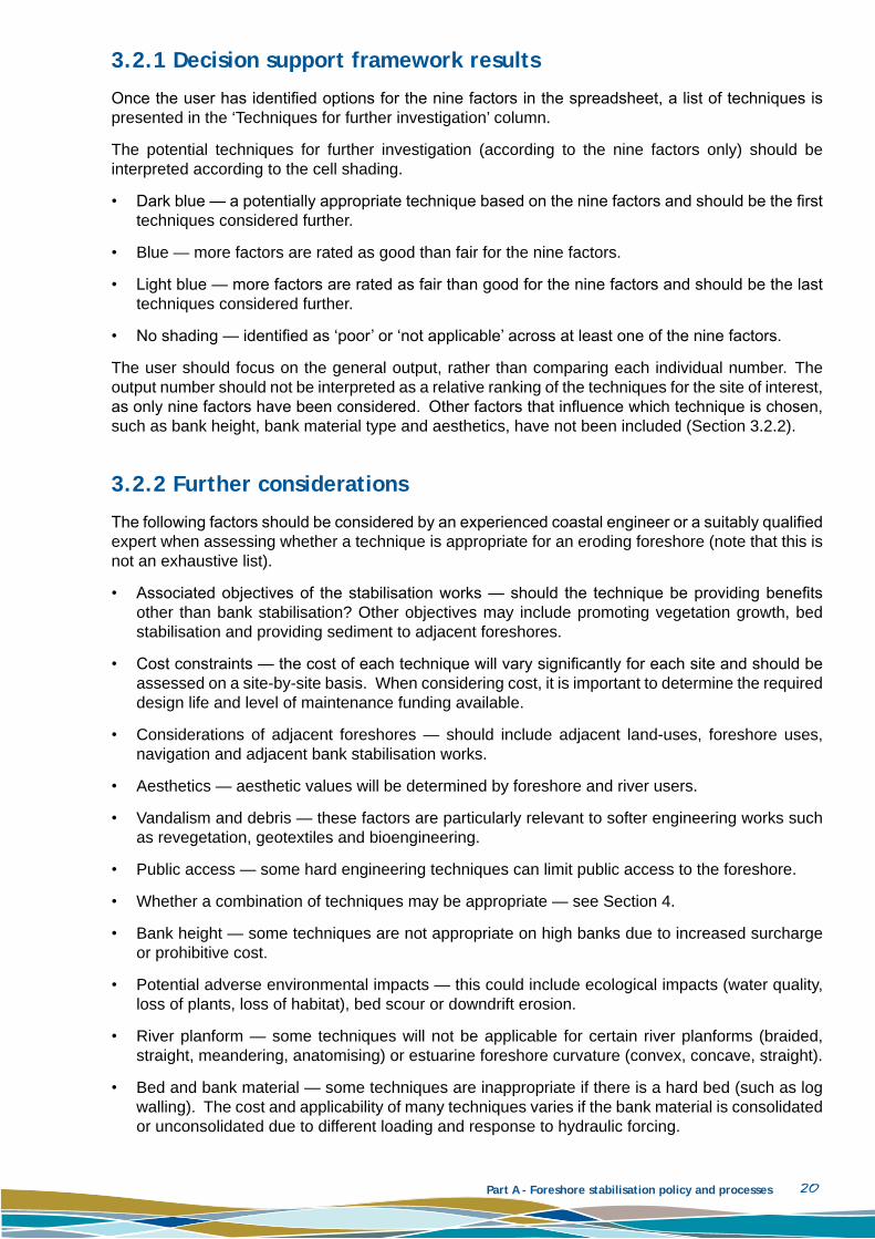
3.2.1 Decision support framework results
Once the user has identified options for the nine factors in the spreadsheet, a list of techniques is presented in the ‘Techniques for further investigation’ column.
The potential techniques for further investigation (according to the nine factors only) should be interpreted according to the cell shading.
Dark blue — a potentially appropriate technique based on the nine factors and should be the first • techniques considered further.
Blue — more factors are rated as good than fair for the nine factors.•
Light blue — more factors are rated as fair than good for the nine factors and should be the last • techniques considered further.
no shading — identified as ‘poor’ or ‘not applicable’ across at least one of the nine factors.•
The user should focus on the general output, rather than comparing each individual number. The output number should not be interpreted as a relative ranking of the techniques for the site of interest, as only nine factors have been considered. Other factors that influence which technique is chosen, such as bank height, bank material type and aesthetics, have not been included (Section 3.2.2).
3.2.2 Further considerations
The following factors should be considered by an experienced coastal engineer or a suitably qualified expert when assessing whether a technique is appropriate for an eroding foreshore (note that this is not an exhaustive list).
Associated objectives of the stabilisation works — should the technique be providing benefits • other than bank stabilisation? Other objectives may include promoting vegetation growth, bed stabilisation and providing sediment to adjacent foreshores.
Cost constraints — the cost of each technique will vary significantly for each site and should be • assessed on a site-by-site basis. When considering cost, it is important to determine the required design life and level of maintenance funding available.
Considerations of adjacent foreshores — should include adjacent land-uses, foreshore uses, • navigation and adjacent bank stabilisation works.
Aesthetics — aesthetic values will be determined by foreshore and river users.•
Vandalism and debris — these factors are particularly relevant to softer engineering works such • as revegetation, geotextiles and bioengineering.
Public access — some hard engineering techniques can limit public access to the foreshore.•
Whether a combination of techniques may be appropriate — see Section 4.•
Bank height — some techniques are not appropriate on high banks due to increased surcharge • or prohibitive cost.
Potential adverse environmental impacts — this could include ecological impacts (water quality, • loss of plants, loss of habitat), bed scour or downdrift erosion.
River planform — some techniques will not be applicable for certain river planforms (braided, • straight, meandering, anatomising) or estuarine foreshore curvature (convex, concave, straight).
Bed and bank material — some techniques are inappropriate if there is a hard bed (such as log • walling). The cost and applicability of many techniques varies if the bank material is consolidated or unconsolidated due to different loading and response to hydraulic forcing.

Part A - Foreshore stabilisation policy and processes 21
Rate of sediment supply or rate of erosion or both — the maintenance requirements for each • technique will vary according to the rates of sediment supply to, and rates of sediment erosion from, the site.
Erosion pathway — this indicates the symptoms of erosion, rather than isolating the cause of the • erosion. Different techniques are applicable for when the erosion is occurring only on the upper bank, if there is large-scale retreat, if the bank is steepening (including undercutting), or if there is lowering of the bed.
Erosion timescale — technique applicability will vary if the erosion is occurring in response to • recent engineering works (such as downdrift of walling); during an event with some recovery; during an event with no to limited recovery; or as a chronic problem (such as due to climate change, altered sediment supply or downdrift of a reclaimed foreshore).
Access to site — managing public access during the works and traffic management.•
Aboriginal heritage — issues related to Aboriginal heritage may prevent excavation at a site and • constrain stabilisation techniques to only maintaining the existing technique or modifying existing techniques, in preference to rebuilding.
Presence of acid sulphate soils — this could influence the selection of materials applicable at • a site. The cost of addressing acid sulphate soils (once disturbed) may also outweigh the cost benefits of a preferred stabilisation technique.
Historic site contamination — the cost of addressing the contamination may outweigh the cost • benefits of a preferred stabilisation technique.
Further scrutiny is required when riffles are presented as an option for foreshore stabilisation. This • is because site-specific hydraulic grades and channel widths have not been incorporated.
Detailed information has been included in Part B for eight direct techniques and in Part C for indirect approaches (for publication in early 2010). This information is presented to assist land managers to prepare a project scope for an experienced coastal engineer or suitably qualified expert in the case of hard structures and indirect stabilisation approaches. It does not remove the need for site-specific designs. Enough detail has been included for land managers to design revegetation and some bioengineering stabilisation projects. However, an experienced environmental and/or coastal engineer and Trust officers should always be consulted before implementing any stabilisation technique on the foreshore.
Part A - Foreshore stabilisation policy and processes 22
4 comBInIng technIqueS
The selection of site-specific stabilising techniques is discussed in Section 3. In particular, a series of steps is outlined that should be followed by a land manager prior to determining if new works will be required. The decision support framework is provided to assist in the selection of the most appropriate techniques to the site.
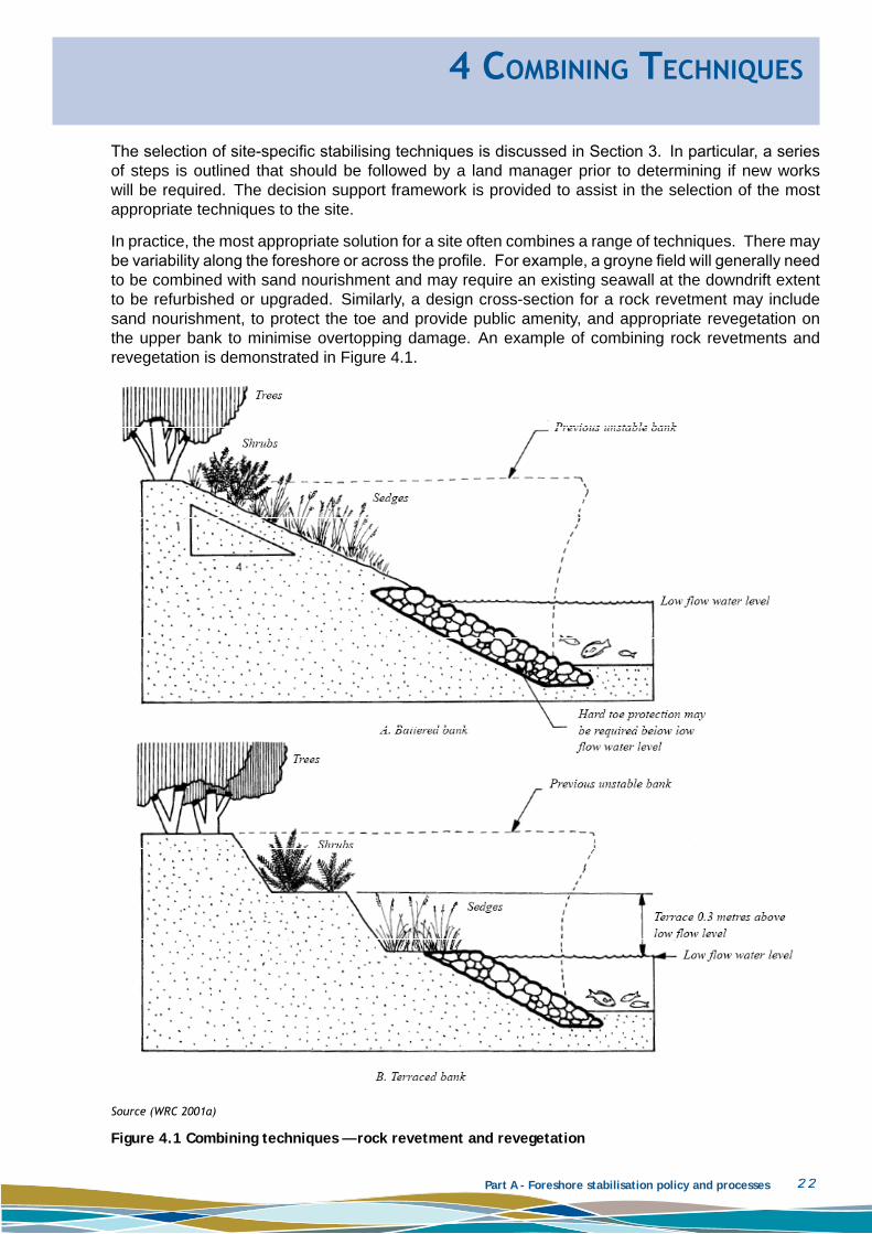
In practice, the most appropriate solution for a site often combines a range of techniques. There may be variability along the foreshore or across the profile. For example, a groyne field will generally need to be combined with sand nourishment and may require an existing seawall at the downdrift extent to be refurbished or upgraded. Similarly, a design cross-section for a rock revetment may include sand nourishment, to protect the toe and provide public amenity, and appropriate revegetation on the upper bank to minimise overtopping damage. An example of combining rock revetments and revegetation is demonstrated in Figure 4.1.
Source (WRC 2001a)
Figure 4.1 Combining techniques — rock revetment and revegetation

Part A - Foreshore stabilisation policy and processes 23
A simple matrix provides guidance to foreshore managers on the potential for combining stabilisation approaches (Table 4.1). Ratings have been made on the basis of engineering, planning and environmental considerations.
Table 4.1 Potential for combining foreshore stabilisation approaches
RE
VE
GE
TATIOn
BIO
En
GIn
EE
RIn
G
GA
BIO
nS
RE
vE
TME
nTS
WA
LLIng
RE
nO
UR
ISH
ME
nT
gR
Oy
nE
S
FLOW
M
OD
IFICATIO
n
REVEGETATIOn y y o y y o y
BIOEnGInEERInG y o o o y y y
GABIOnS y o o y o o o
REvETMEnTS o o o y o o o
WALLIng y o y y o o o
REnOURISHMEnT y y o o o y o
gROynES o y o o o y o
FLOW MODIFICATIOn y y o o o o o
Rating: y= good, o = Fair/neutral
The following list provides a number of comments and considerations for combining foreshore stabilisation techniques.
Combining maintenance of an existing structure, extending or raising this structure, and introducing 1 a new foreshore stabilisation technique may be more appropriate in many circumstances than demolishing an existing structure or constructing an entirely new system.
Revegetation and bioengineering approaches are generally compatible. These approaches can 2 be combined with relative ease and can lead to good environmental and planning outcomes.
Revegetation is complementary to large woody debris and can be undertaken landward of, next 3 to, and (in some instances) in front of, hard structures.
Coir logs and brush mattressing should always be combined with revegetation. Coir logs combine 4 well with brush mattressing, erosion control matting, bank reshaping, large woody debris and rock toe protection. In some situations, there may be opportunities for using coir logs in front of hard structures, such as revetments and log walls, which provide a mechanism to allow revegetation in front of hard structures.
Brush mattressing generally requires some form of toe protection in the form of coir logs, rock 5 (in the form of a small revetment) or anchored large woody debris. Brush mattressing can be placed above any type of structure that provides sufficient toe protection if the slope above the structure does not exceed 1H:4v.
The combination of some traditional engineering approaches (gabions, revetments, walling) 6 with revegetation and bioengineering approaches can have many advantages. Revegetating the upper bank of a low profile revetment, in areas subject to only occasional wave attack, can reduce the revetment cost and be more aesthetically acceptable. Revegetation of degraded foreshores combined with sand nourishment to protect the revegetation and provide amenity, may be appropriate in a range of locations.
Log walling can be combined with rock toe protection in front of the structure. Revegetation with 7 sedges can also be placed in front of log walling if the walling is set back sufficiently from the river.

Part A - Foreshore stabilisation policy and processes 24
This improves the aesthetics and can reduce the level of scour in front of the structure. However, the increased wave reflection may reduce the life of the sedges. Revegetation, with stabilising measures such as brush mattressing or geotextile matting, can also be incorporated above log walling. However, the placement of large trees or the presence of steep slopes may increase loading on the structure and should be considered in the design.
The combination of some traditional engineering approaches (groynes, walling) is common 8 practice. However, good planning would generally limit the range of traditional engineering approaches applied at a site. Appropriate, and often used, combinations include walling with a revetment toe, groynes with sand renourishment, and walling with a gabion mattress toe.
Stepped gabion walling can be designed in combination with revegetation (landward and in 9 front of the structure) and renourishment. Gabions can be placed adjacent to other engineered structures.
Sand renourishment is often combined successfully with other techniques. The construction of 10 groynes generally requires sand renourishment updrift of the groynes to allow natural bypassing to continue and downdrift erosion to be minimised. Care should be taken in combining sand renourishment with revetments or walling as enhanced wave reflection can result in increased erosion of the nourished sand.
Channel excavation can be combined with almost any direct stabilisation technique. The most 11 applicable combination is with renourishment projects, as the excavated sediment can be used as the sediment source.
Large woody debris is generally accompanied by revegetation which may include plantings on the 12 upper bank and between the woody debris. The proper application of these structures will often result in deposition of sediment on top of or behind the woody debris. This accretion provides an opportunity for revegetation or colonisation with permanent bank-stabilising vegetation.
Combined techniques are often required at the ends of structures. In practice these transitions 13 are often constructed in a responsive manner. For example, erosion downdrift of a seawall may initiate placement of rock to minimise downdrift scour. As a general principle, the design approach should always consider the updrift and downdrift implications of any new works. Protecting one stretch of foreshore at the expense of another should generally be discouraged unless planned retreat of the downdrift foreshore is accepted management.
There are few combinations of foreshore stabilisation techniques that are considered so poor as 14 to not warrant consideration. When considering foreshore stabilisation at the higher approach level, any combination of approaches is theoretically possible. For example, while walling can enhance erosion of sand nourishment, there may be sites where an appropriately setback seawall provides a last line of defence to valuable assets when required, while the sand nourishment provides the primary foreshore protection under most circumstances.
An important design consideration when combining techniques is that many effective 15 foreshore protection structures are flexible and can sustain damage while remaining relatively effective. Combining a flexible structure (such as a geofabric sand container revetment) with a fixed structure (such as a limestone block seawall) requires careful consideration, at the design stage, of relative movement between flexible and fixed structures.
Consider the opportunities for combining techniques to manage foreshore erosion as presented below.
Is managed retreat/do nothing most appropriate at this site? This permits bank erosion to • continue, reducing downdrift erosion, and allows the river to migrate. This approach may require fencing, signage and moving infrastructure at risk of damage.
What are the existing techniques used in the foreshore?•
Are the existing techniques effective?•
Is the cause and magnitude of foreshore erosion understood?•

Part A - Foreshore stabilisation policy and processes 25
Is the foreshore erosion caused or influenced by the existing technique?•
Do the existing techniques match the environmental and social values of the foreshore? •
Is a low intervention technique or maintenance of an existing structure possible?•
Is it possible to extend or upgrade an existing technique to manage the foreshore erosion?•
If a new technique is proposed, is it compatible with the existing technique?•
Are there advantages (financial, social, environmental) in combining techniques either along or • across the foreshore?
What are the site access constraints?•
What are the likely labour and plant requirements?•
Is the local community likely to accept the proposal?•
Often good foreshore planning results in a range of appropriate techniques being applied at a particular site.

Part A - Foreshore stabilisation policy and processes 26
5 FactorS to conSIder when revIewIng propoSed workS
Proposed foreshore stabilisation works by a local or state government agency or private landowner on the Swan Canning river system generally requires approval from the Trust (Section 2). The Trust may seek advice from specialist government agencies, such as the Department of Planning’s coastal engineering group, for larger or more complex foreshore stabilisation structures. The Trust considers any proposal in the context of existing amenity, and social and environmental values for the Swan Canning river system (Section 2).
A checklist for reviewing proposed engineering works is provided in Table 5.1. This checklist can be used by the local or state government agency or a private landowner when liaising with consulting engineers, and by Trust officers when assessing foreshore stabilisation proposals.
A design requires consideration of functional use, implication of atypical conditions, adaptability to changing conditions and impact on adjacent activities.
It is also important to note that the majority of erosion control works need to occur at specific times of the year. Most foreshore works are best scheduled for low tides during spring and summer, with any revegetation occurring in winter (upland plants) and spring/summer (lower lying plants). Timing is an important consideration for all proposed works and should be considered at an early stage so that works can be planned to occur at appropriate times.
Further information on technique-specific considerations are contained in the relevant sections in Part B and Part C. Considerations for combining techniques are included in Section 4.
Table 5.1 Generic checklist for reviewing proposed works
STEP REVIEW FACTOR
1
Establish functional use
Ensure that the proposed works can be used for its intended purpose•
Identify the range of conditions for which there are no constraints to land use•
Determine the frequency with which there are no constraints to land use•
2
Assess implications of atypical conditions
Identify how atypical conditions affect use of the proposed works•
Determine if structural modifications may improve use•
Determine management actions to improve use or minimise implications of experiencing • atypical conditions
Identify how limitations to use may be communicated to users•
3
Adaptability to changing conditions (e.g. bed movement; change to the proposed works use; climate change)
Determine if the proposed works may be modified to suit changing conditions•
Evaluate whether management actions may be economically modified to suit changing • conditions
4Impact on adjacent activities (e.g. access; bed change; noise)
Identify whether the proposed works may detrimentally affect activities adjacent to the site•
5Reliance on adjacent activities
Determine if the proposed works and its management are contingent on adjacent activities • (e.g. joint dredging works; bridge clearance)

Part A - Foreshore stabilisation policy and processes 27
STEP REVIEW FACTOR
6Structural capacity to withstand design loads
Ensure the structure meets relevant Australian Standards•
7
Structural capacity to withstand incidental loads
Identify possible sources of unusual loading (vessel collision; construction/maintenance • surcharge)
Evaluate likelihood of conditions likely to cause failure•
8
Effect of exceeding design loads
Define failure modes and mechanisms•
Determine consequences of failure•
Identify possible redundancy•
9
Indications of failure
Determine whether mechanisms of potential failure may be measured prior to failure • occurring
Assess the adequacy and ease of monitoring and maintenance requirements•
10
Durability
Define desired structural life•
Determine potential for corrosion•
Identify parts susceptible to fatigue loading•
Evaluate likelihood of wear or breakage•
11
Internal stability
Determine reliance of the components of the proposed works on other parts•
Evaluate whether the resilience of component parts is commensurate with their importance • to the large structure and ability to undertake maintenance
12
Maintenance
Determine a likely or possible program of maintenance•
Ensure regular maintenance activities can be completed•
13
Safety associated with functional use
Evaluate hazards associated with normal use of the proposed works•
Determine whether structural modifications or management actions may be undertaken • effectively
14
Safety associated with atypical conditions
Determine conditions where safety may be adversely affected (e.g. instability)•
Consider whether external hazards (e.g. fire) have been adequately catered for through • structures and management actions
15
Financial considerations
Assess capital cost•
Estimate ongoing costs•
Consider distribution of costs, including indirect costs•
Consider reliability of funding sources•

Part A - Foreshore stabilisation policy and processes 28
STEP REVIEW FACTOR
16
Timing considerations
Specific works need to occur at appropriate times•
Consider the timing needs for each component of the project•
Consider a proposed timeline for works and include options if delays arise•

Part A - Foreshore stabilisation policy and processes 29
6 mappIng
A series of maps has been developed using the decision support framework outlined in Section 3. The maps identify appropriate areas for applying key stabilisation approaches.
The decision support framework was applied across the Swan Canning river system on a segment-by-segment scale. Each segment was generally delineated by the following changes to hydrodynamic forces during the foreshore assessment fieldwork (2003–2007) (Damara 2007; Oceanica et al. 2007):
a significant barrier to alongshore sediment transport was identified;•
the shoreline changes aspect by more than 45°; or•
a perceptible change in active stresses occurs, evidenced as a change in: shore type; level of • erosion; and/or upper slope or floodplain characteristics.
A segment was only distinguished if it was greater than 20m long.
The application of the decision support framework was based on data collected during the foreshore assessment, aerial photographs, bathymetry data, flood levels, wave information and expert engineering opinion. This assessment was conducted at a high level and further investigation should always be undertaken at each site before starting any works.
Two series of maps, and summary statistics, have been produced demonstrating:
the minimum level (as defined in Section 6.1) of potential direct shore stabilisation approaches; •
the potential application of any indirect approaches.•
6.1 dIrect StaBIlISatIon approacheS
The first series of maps and statistics demonstrate the areas of potential application of direct shore stabilisation approaches. These maps have a hierarchy of four foreshore protection approaches of increasing intervention where managed retreat is the lowest level.
Managed retreat (with revegetation where possible)1
Revegetation (with bioengineering where required)2
Light built protection (wave baffle boards, log walling, sandbag walls, rock toe with resloping, 3 sandbag revetments and geotextile revetments)
Hard built protection (all other walls, gabions and revetments).4
The maps display the minimum level of appropriate direct bank stabilisation works required, based on the above hierarchy. Summary statistics for the minimum level of appropriate direct stabilisation works for each local government authority are presented in Table 6.1.
As discussed in Section 6, the assessment to determine the application of shore stabilisation approaches was conducted at a high level and further detailed investigation and planning should be undertaken on a site-by-site basis. Wherever possible, techniques that provide greater environmental value such as revegetation and bioengineering are preferable. If this is not possible, every effort should be made to combine the chosen technique with revegetation and/or bioengineering.

Part A - Foreshore stabilisation policy and processes 30
Table 6.1 Minimum direct stabilisation approach for local government authorities
LgA(Local government authority)
MAnAgED RETREAT
REVEGETATIOn WITH BIOEnGInEERInG
LIgHT BUILT PROTECTIOn
HARD BUILT PROTECTIOn
km % LgA km % LgA km % LgA km % LgA
Claremont 1.9 100% 0.0 0% 0.0 0% 0.0 0%
East Fremantle 0.0 0% 0.0 0% 0.4 11% 3.1 89%
Fremantle 1.2 40% 0.1 4% 0.3 12% 1.3 44%
Melville 11.8 62% 2.7 14% 2.4 13% 2.1 11%
Mosman Park 3.8 80% 0.2 5% 0.0 0% 0.7 15%
nedlands 1.2 24% 0.0 0% 0.6 11% 3.2 65%
Peppermint Grove 0.3 21% 0.9 54% 0.4 24% 0.0 0%
Perth 2.2 18% 3.4 29% 0.2 2% 6.1 51%
South Perth 8.4 47% 3.8 21% 1.1 6% 4.6 26%
Subiaco 0.9 32% 1.6 55% 0.4 13% 0.0 0%
Victoria Park 3.4 58% 1.6 28% 0.1 2% 0.7 13%
Bassendean 3.2 66% 1.1 23% 0.0 0% 0.5 11%
Bayswater 6.9 75% 0.5 6% 0.0 0% 1.4 16%
Belmont 5.1 55% 1.9 21% 0.4 4% 1.9 20%
Swan 82.4 98% 1.3 2% 0.0 0% 0.2 0%
Vincent 0.0 0% 0.2 100% 0.0 0% 0.0 0%
Armadale 2.8 50% 2.8 50% 0.0 0% 0.0 0%
Canning 18.9 90% 1.3 6% 0.7 4% 0.1 1%
Gosnells 30.1 92% 1.8 6% 0.0 0% 0.7 2%
Note: The most prevalent minimum direct approach is shown in bold

Part A - Foreshore stabilisation policy and processes 31
Figure 6.1 Mimimum direct stabilisation approaches for the Swan Canning Estuary

Part A - Foreshore stabilisation policy and processes 32
Figure 6.2 Mimimum direct stabilisation approaches for the Swan River

Figure 6.3 Mimimum direct stabilisation approaches for the Swan River (continued)
Part A - Foreshore stabilisation policy and processes 33

Part A - Foreshore stabilisation policy and processes 34
Figure 6.4 Mimimum direct stabilisation approaches for the Canning River

Part A - Foreshore stabilisation policy and processes 35
6.2 IndIrect StaBIlISatIon approacheS
The second series of maps and statistics demonstrate where the following indirect methods may be appropriate.
Do nothing (no indirect stabilisation approaches are appropriate) 1
Renourishment 2
groynes/headlands 3
Flow modification (baffles/vanes, riffles, channel excavation and woody debris)4
Applying the decision support framework requires user input of nine factors that determine potential stabilisation techniques (Section 3). The indirect stabilisation approaches identified for each segment were not mutually exclusive (like the direct stabilisation approaches). In several segments it would be possible to implement all three indirect stabilisation approaches.
Summary statistics for locations where indirect stabilisation works may be appropriate for each local government authority are presented in Table 6.2 and Table 6.3.
As discussed in Section 6, the assessment to determine the application of shore stabilisation approaches was conducted at a high level and further detailed investigation and planning should be undertaken on a site-by-site basis. Wherever possible, techniques that provide greater environmental value such as revegetation and bioengineering are preferable. If this is not possible, every effort should be made to combine the chosen technique with revegetation and/or bioengineering.

Part A - Foreshore stabilisation policy and processes 36
Table 6.2 Indirect stabilisation approach statistics for local government authorities presented as mutually exclusive options
LOCAL gOvERnMEnT AUTHORITy
nO
InD
IRE
CT
RE
nO
UR
ISH
ME
nT
On
Ly
gR
Oy
nE
S O
nLy
FLO
W M
OD
IFIC
ATIO
n
On
Ly
RE
nO
UR
ISH
ME
nT
An
D/O
R g
RO
yn
ES
RE
nO
UR
ISH
-ME
nT
An
D/O
R F
LOW
M
OD
IFIC
ATIO
n
ALL
TH
RE
E In
DIR
EC
T A
PP
RO
AC
HE
S
CO
ULD
BE
C
On
SID
ER
ED
km % LgA km %
LgA km % LgA km %
LgA km % LgA km %
LgA km % LgA
Claremont 1.0 56% 0.0 0% 0.0 0% 0.0 0% 0.0 1% 0.0 0% 0.8 43%
East Fremantle 2.9 83% 0.2 7% 0.0 0% 0.0 0% 0.2 5% 0.0 0% 0.2 5%
Fremantle 2.0 67% 0.0 0% 0.5 18% 0.0 0% 0.0 0% 0.0 0% 0.5 15%
Melville 2.0 11% 4.4 23% 0.0 0% 0.4 2% 7.6 40% 1.0 5% 3.5 18%
Mosman Park 2.6 56% 0.0 0% 0.0 0% 0.7 14% 0.7 15% 0.0 0% 0.7 14%
nedlands 1.5 31% 1.6 34% 0.0 0% 0.0 0% 1.3 26% 0.0 0% 0.5 9%
Peppermint Grove 0.6 39% 0.0 0% 0.0 0% 0.0 0% 0.2 13% 0.0 0% 0.8 48%
Perth 2.0 17% 4.9 42% 0.3 2% 2.5 21% 0.0 0% 1.3 11% 0.8 7%
South Perth 0.4 2% 7.2 40% 0.2 1% 0.0 0% 5.5 31% 0.0 0% 4.6 26%
Subiaco 0.0 0% 1.4 46% 0.0 0% 0.6 22% 0.0 0% 0.0 0% 0.9 32%
Victoria Park 0.7 13% 2.6 45% 0.0 0% 0.0 0% 0.0 0% 1.7 28% 0.8 14%
Bassendean 0.5 11% 3.4 71% 0.0 0% 0.9 18% 0.0 0% 0.0 0% 0.0 0%
Bayswater 1.6 18% 5.3 58% 0.0 0% 1.0 12% 0.0 0% 1.1 12% 0.0 0%
Belmont 0.9 9% 6.4 68% 0.0 0% 1.0 10% 0.0 0% 1.1 12% 0.0 0%
Swan 22.8 27% 2.7 3% 0.0 0% 57.7 69% 0.0 0% 0.7 1% 0.0 0%
Vincent 0.0 0% 0.2 100% 0.0 0% 0.0 0% 0.0 0% 0.0 0% 0.0 0%
Armadale 0.5 10% 0.0 0% 0.0 0% 5.0 90% 0.0 0% 0.0 0% 0.0 0%
Canning 1.0 5% 2.8 13% 0.0 0% 12.9 61% 1.6 8% 0.0 0% 2.7 13%
Gosnells 0.5 1% 0.2 1% 0.0 0% 31.9 98% 0.0 0% 0.0 0% 0.0 0%
Note: The most prevalent combination of indirect approaches is shown in bold

Part A - Foreshore stabilisation policy and processes 37
Table 6.3 Indirect stabilisation approach statistics for local government authorities
LOCAL gOvERnMEnT AUTHORITy
nO InDIRECT REnOURISHMEnT gROynES FLOW MODIFICATIOn
km % LgA km % LgA km % LgA km % LgA
Claremont 1.0 56% 0.8 44% 0.8 44% 0.8 43%
East Fremantle 2.9 83% 0.6 17% 0.4 11% 0.2 5%
Fremantle 2.0 67% 0.5 15% 1.0 33% 0.5 15%
Melville 2.0 11% 16.5 87% 11.1 59% 4.9 26%
Mosman Park 2.6 56% 1.4 30% 1.4 30% 1.3 29%
nedlands 1.5 31% 3.4 69% 1.7 35% 0.5 9%
Peppermint Grove 0.6 39% 1.0 61% 1.0 61% 0.8 48%
Perth 2.0 17% 7.1 60% 1.1 10% 4.6 39%
South Perth 0.4 2% 17.3 97% 10.3 57% 4.6 26%
Subiaco 0.0 0% 2.3 78% 0.9 32% 1.6 54%
Victoria Park 0.7 13% 5.1 87% 0.8 14% 2.5 43%
Bassendean 0.5 11% 3.4 71% 0.0 0% 0.9 18%
Bayswater 1.6 18% 6.4 70% 0.0 0% 2.1 23%
Belmont 0.9 9% 7.5 81% 0.0 0% 2.1 22%
Swan 22.8 27% 3.4 4% 0.0 0% 58.5 70%
Vincent 0.0 0% 0.2 100% 0.0 0% 0.0 0%
Armadale 0.5 10% 0.0 0% 0.0 0% 5.0 90%
Canning 1.0 5% 7.2 34% 4.3 21% 15.6 74%
Gosnells 0.5 1% 0.2 1% 0.0 0% 31.9 98%
Note: The most prevalent indirect approach is shown in bold — the indirect approaches are not presented as mutually exclusive in this table

Part A - Foreshore stabilisation policy and processes 38
Figure 6.5 Potential indirect stabilisation approaches for the Swan Canning Estuary

Part A - Foreshore stabilisation policy and processes 39
Figure 6.6 Potential indirect stabilisation approaches for the Swan River

Figure 6.7 Potential indirect stabilisation approaches for the Swan River (continued)
Part A - Foreshore stabilisation policy and processes 40

Part A - Foreshore stabilisation policy and processes 41
Figure 6.8 Potential indirect stabilisation approaches for the Canning River

Part A - Foreshore stabilisation policy and processes 42
7 acknowledgementS
The development of the report was funded by the Swan River Trust in collaboration with the Eastern Metropolitan Regional Council.
This document is based on a report to the Trust prepared by Oceanica Consulting Pty Ltd in conjunction with Damara WA Pty Ltd and Shore Coastal Pty Ltd. The chapters on revegetation and coir logs were prepared by the Trust.
The report has been reviewed by MP Rogers and Associates and the section on brush mattressing was reviewed by Thomas Schwarten (Syrinx Environmental Pty Ltd).
We also acknowledge the local government authorities and state government agencies whose project work has been documented throughout this report.

Part A - Foreshore stabilisation policy and processes 43
8 BIBlIography
American Association of State Highway and Transportation Officials (AASHTO), M288-96 Standard Specifications for geotextiles, <www.usfabricsinc.com/products/Aashto.shtml#pdfs>.
Avon Catchment Council 2008, Aquatic Ecosystems, <http://www.avonnaturaldiversity.org/index.php?option=com_content&task=view&id=50&Itemid=75&limit=1&limitstart=2>.
Allen, HH & Fischenich, JC 2000, ‘Coir Geotextile roll and wetland plants for streambank erosion control’ in EMRRP vol. Technical Notes Collection (ERDC Tn-EMRRP-SR-04).
Allen, HH & Fischenich, jC 2001, ‘Brush Mattresses for Streambank Erosion Control’ in EMRRP Technical Notes Collection (ERDC Tn EMRRP- SR-23), p. 9.
Allen, H & Leech, jR 1997, Bioengineering for Streambank Erosion Control – Report 1 – Guidelines, Prepared by US Army Corps of Engineers, Report no. Technical Report EL-97-8.
AnZECC/ARMCAnZ 2000, Australian and New Zealand Guidelines for Fresh and Marine Water Quality, Australian and new Zealand Environment and Conservation Council & Agriculture and Resource Management Council of Australia and new Zealand.
Barr, S & Brodie-Hall, B 2005, ‘State government Responsibility for Maintenance Dredging in WA’, Proceedings of the Australasian Coastal & Ports 2005 conference, Adelaide, Australia.
Bendell 2006, Recommendations for Appropriate Shoreline Stabilisation Methods for the different North Carolina Estuarine Shoreline Types, north Carolina Division of Coastal Management, USA.
Bentrup, G & Hoag, JC 1998, The Practical Streambank Bioengineering Guide – User’s Guide for Natural Streambank Stabilization Techniques in the Arid and Semi-arid Great Basin and Intermountain West, USDA natural Resources Conservation Service, Abderdeen, Idaho, USA.
Biedenharn, DS, Elliott, CM & Watson, CC 1997, The WES Stream Investigation and Streambank Stabilisation Handbook, Prepared by US Army Engineer Waterways Experiment Station, Vicksburg, Mississippi, USA.
Blankenship, Tk, Evaluating the Condition of Seawalls/Bulkheads, Prepared by Coastal Systems International, Coral gables, FL, USA.
Boeters, R, Verheij, H & van der Wal. 1991, Environment-friendly bank protections, Delft Hydraulics. Publication no. 464.
Breteler, Mk & Pilarczyk, kW 1998, ‘Chapter 16: Alternative revetments’, in Dikes and Revetments, ed. kW Pilarczyk, AA Balkema.
Brisbane City Council 2004, Erosion Treatments for Urban Creek Guidelines, Version 3, Brisbane, Australia.
British Columbia Ministry of Environment (BCMoE) 2006, Best Management Practices for Lakeshore Stabilisation, British Columbia Ministry of Environment, Penticton, British Columbia.
British Standards Institution 1991, British standard: maritime structures – part 5: Code of practice for dredging and land reclamation, (BS 6349-5-1991), British Standards, United kingdom.
British Standards Institution 1991, British standard: maritime structures – part 7: Guide to the design and construction of breakwaters, (BS 6349-7-1991), British Standards, United kingdom.
British Standards Institution 2000, British standard: maritime structures – part 1: Code of practice for general criteria, (BS 6349-1-2000), British Standards, United kingdom.
Brooks, AP, Abbe, TB, jansen, jD, Taylor, M & gippel, Cj 2001, ‘Putting the wood back into our rivers: an experiment in river rehabilitation’, In Rutherfurd, I, Sheldon, F, Brierley, g & kenyon, C,

Part A - Foreshore stabilisation policy and processes 44
(Eds.), Third Australian Stream Management Conference: the Value of Healthy Streams, 27–29 August, pp. 73–80, Brisbane, Australia.
Broome, SW, Rogers, SM jr & Seneca, ED 1992, Shoreline Erosion Control using Marsh Vegetation and Low-Cost Structures, UnC Sea Grant College Publication, Report no. UnC-SG-92-12.
Brown, CT 1979, Gabion Report. Some factors affecting the use of Maccaferri gabions and reno mattresses for coastal revetments, University of new South Wales Water Research Laboratory, Report no. 156, Sydney, new South Wales.
Brown, SA & Clyde, ES 1989, Design of Riprap Revetment – HEC 11 Metric Version, Prepared by U.S. Department of Transportation Federal Highway Adminisation, Report no. FHWA-IP-89-016 - HEC-11.
Bundesanstalt für Wasserbau (BAW) 2005, Principles for the Design of Bank and Bottom Protection for Inland Waterways, Prepared by Federal Waterways Engineering and Research Institute (Bundesanstalt für Wasserbau), Bulletin no. 88, karlsruhe, germany.
Caltrans 2003, ‘geotextiles, Mats, Plastic Covers and Erosion Control Blankets’, in Construction Site Best Management Practices Manual, pp. 3–7.
Cederholm, CJ, Bilby, RE, Bisson, PA, Bumstead, TW, Fransen, BR, Scarlett, WJ & Ward, JW 1997, ‘Response of juvenile coho salmon and steelhead to placement of large woody debris in a coastal washing stream,’ North American Journal of Fisheries Management, vol. 17, pp. 947–963.
Chambers, J 1987, ‘The Importance of Fringing Vegetation to the Swan–Canning Estuary’, in The Swan River Estuary, Ecology and Management: Proceedings of a symposium on the Swan–Canning River Estuarine System, Western Australia, ed. J. John, Environmental Studies Group, Curtin University of Technology, Western Australia.
Chen, yH & Cotton, gk 1988, ‘Design of roadside channels with flexible linings’, Prepared by US Department of Transportation – Federal Highway Administration, Report no. Hydraulic Engineering Circular No. 15. Publication No. FHWA-IP-87-7, Virginia, USA.
Christopher B. Burke Engineering, Ltd. (CBBEL) 1999, Indiana Drainage Handbook, Section 5.5 ‘Practice 505 brush mattress’, Indiana Department of natural Resources Division of Water, Indiana, USA. Available at: <http://www.in.gov/dnr/water/files/allhbook.pdf>.
Collison, jC & Simon, A 2001, ‘Beyond root reinforcement: The hydrologic effects of riparian vegetation on riverbank stability’ in Proceedings of the Conference Wetlands Engineering and River Restoration, American Society of Civil Engineers, Reston, VA, USA.
Colorado Department of Transportation (CDOT) 2004, Drainage Design Manual, CDOT, Colorado, USA.
Construction Industry Research and Information Association (CIRIA) 2007, The Rock Manual – the Use of Rock in Hydraulic Engineering (2nd Edition), C683, Construction Industry Research and Information Association, London, Uk.
Copeland, RR 2000, Determination of flow resistance coefficients due to shrubs and woody vegetation, Prepared by U. S. Army Engineer Waterways Experiment Station, Report no. Technical note no. ERCD/CHL CHETn-vIII-3, vicksburg, Mississipi, USA.
Copeland, RR, McComas, Dn, Thorne, CR, Soar, Pj, jonas, MM & Fripp, jB 2001, Hydraulic Design of Stream Restoration Projects, Prepared by U.S. Army Corps of Engineers: Engineer Research and Development Center, Report no. Technical Report ERDC/CHL TR-01-28, vicksburg, Mississipi, USA.
Cottingham, P, Bond, n, Lake, PS & Outhet, D 2005, Recent Lessons on River Rehabilitation in Eastern Australia, Technical Report, CRC for Freshwater Ecology, Canberra, ACT.
Crossman, M & Simm, j 2004, Manual on the Use of Timber in Coastal and River Engineering, HR Wallingford.

Part A - Foreshore stabilisation policy and processes 45
Crowe, RE, Sent, DF & Martin, S 1995, The Protection and Rehabilitation of Dams Using Cellular Confinement Systems, Presto Products Company.
Damara 2006, ‘Swan River Lower Estuary – Inundation Assessment’, Unpublished report to the Swan River Trust, Perth, Western Australia.
Damara 2007, ‘Swan River Lower Estuary – Foreshore Condition Assessment’, Unpublished report to the Swan River Trust, Perth, Western Australia.
Damara WA 2007b, ‘Swan River Foreshore Wave Climate Assessment’, Unpublished report to the Swan River Trust, Perth, Western Australia.
D’Aoust, Sg & Millar, Rg 2000, ‘Stability of ballasted woody debris habitat structures’, Journal of Hydraulic Engineering, vol. 126, no. 11, pp. 810–817.
Davis, jE & Maynord, ST 1998, ‘Shoreline and Channel Erosion Protection: Overview of Alternatives’, Prepared for WRP Notebook, Report no. WRP Technical Note HS-RS-4.1.
Department of Environment (DoE) 2006, River Restoration – how much does it cost? Plus some rehabilitation and construction tips, Department of Environment, Perth, Western Australia.
Department of Environment (DoE) & Swan River Trust 2005, Stormwater Management Manual for Western Australia: Chapter 7 non-Structural Controls, Department of Environment and Swan River Trust, Perth, Western Australia.
Department of Environment and Conservation (DEC) 2008a, Acid Sulfate Soils fact sheets and guidelines, Department of Environment and Conservation, Perth, Western Australia, available at: <www.dec.wa.gov.au/ass>.
Department of Environment and Conservation (DEC) 2008b, Contaminated Sites fact sheets, Department of Environment and Conservation, Perth, Western Australia, available at: <www.dec.wa.gov.au/pollution-prevention/contaminated-sites/fact-sheets.html>.
Department of Infrastructure Planning and natural Resources (DIPnR) 2004, Georges River Catchment. Guidelines for better practice in foreshore works, Department of Infrastructure Planning and natural Resources, Sydney, nSW.
Department of Primary Industries and Water (DPIW) 2003, Waterways & Wetlands Works Manual: Best Management Practices 6 – Managing Large Woody Debris, Department of Primary Industries and Water, Tasmania.
Donat, M 1995, Bioengineering techniques for streambank restoration. A review of central European practices, Prepared by Ministry of Environment Lands and Parks Ministry of Forests, Report no. Watershed Restoration Project Report no 2, Vancouver, Canada.
Eastern Metropolitan Regional Council (EMRC) 2007, 4.1 Foreshore Management: Policy & Guidelines for Local Government, Eastern Metropolitan Regional Council, Perth, Western Australia.
Ebeling, R, Azene, M & Strom, R 2002, Simplified Procedures for the Design of Tall, Flexible Anchored Tieback Walls, Prepared for US Army Corps of Engineers, Report no. ERDC/ITL TR-02-9, vicksburg, Mississippi, USA.
Eliot Mj, Travers A & Eliot I 2006, ‘Morphology of a Low-Energy Beach, Como Beach, Western Australia’, Journal of Coastal Research, 22 (1), 63–77, Perth, Western Australia.
Ellis, JT, Sherman, DJ, Bauer, BO & Hart, J 1998, ‘Assessing the Impact of an Organic Restoration Structure on Boat Wake Energy’, Journal of Coastal Research, vol. SI 36, ICS 2002 Proceedings, pp. 256–265.
Erosion Control Technology Council (ECTC) 2001, Erosion Control Technology Council (ECTC) Guidance Manual, Prepared by Erosion Control Technology Council, Texas, USA, available at <http://www.ectc.org/guide/index.html>.

Part A - Foreshore stabilisation policy and processes 46
Erosion Control Technology Council (ECTC) 2004, Standard Specification for Rolled Erosion Control Products, Erosion Control Technology Council, Texas, USA, available at <http://www.ectc.org/guide/index.html>.
Federal Emergency Management Authority (FEMA) 2002, Coastal Construction Manual: Principles and Practices of Planning, Siting, Designing, Constructing, and Maintaining Residential Buildings in Coastal Areas, Third Edition, Federal Emergency Management Authority, Report no. FEMA 55.
Fischenich, C 2001, Stability Thresholds for Stream Restoration Materials, Ecosystem Management and Restoration Research Program, United States Army Corps of Engineers, Report no. ERDC Tn-EMRRP-SR-29, vicksburg, Mississippi, USA.
Fischenich, C & Morrow, j 2000, Streambank Habitat Enhancement with Large Woody Material, U.S. Army Engineer Research and Development Center, Report no. EMRRP Technical notes Collection (ERDC Tn-EMRRP-SR-13), vicksburg, Mississippi, USA.
Fischenich, C & Seal, R 2000, Boulder clusters, U.S. Army Engineer Research and Development Center, Report no. EMRRP Technical notes Collection (ERDC Tn-EMRRP-SR-11), vicksburg, Mississippi, USA.
Fischenich, JC 2000, Impacts of Streambank Stabilization Structures WRAP Report, U.S. Army Engineer Research and Development Center, vicksburg, Mississippi, USA.
Fischenich, JC 2001, Impacts of stabilization measures, U.S. Army Engineer Research and Development Center, Report no. EMRRP Technical notes Collection (ERDC Tn-EMRRP-SR-32), vicksburg, Mississippi, USA.
Fischenich, JC & Allen, H 2000, Soil Bioengineering in Stream Management, U.S. Army Engineer Research and Development Center, Report no. (ERDC/EL SR-W-00-1), vicksburg, Mississippi, USA.
Fischer, RA & Fischenich, JC 2000, Design recommendations for riparian corridors and vegetated buffer strips, U.S. Army Engineer Research and Development Center, Report no. EMRRP Technical notes Collection (ERDC Tn-EMRRP-SR-24), vicksburg, Mississippi, USA.
Freeman, GE & Fischenisch, CJ 2000, Gabions for Streambank Erosion Control, EMRRP Technical notes Collection (ERDC Tn-EMRRP-SR-22), U.S. Army Engineer Research and Development Center, vicksburg, Mississippi, USA.
Freeman, GE, Rahmeyer, WH & Copeland, RR 2000, Determination of resistance due to shrubs and woody vegetation, U. S. Army Engineer Waterways Experiment Station, Report no. Technical Report no. ERDC/CHL TR-00-25, vicksburg, Mississippi, USA.
Frissell, CA & nawa, Rk 1992, ‘Incidence and causes of physical failure of artificial habitat structures in streams of western Oregon and Washington,’ in North American Journal of Fisheries Management, vol 12, pp. 182–197.
Geofabrics Australia 2008, ELCOROCK® News, WRL Flume Testing, volume 1, Oct 2008.
gHD 2008, ‘Draft Report for Environmental Flows and Objectives: Swan and Canning Rivers’, Unpublished report to Swan River Trust, Perth, Western Australia.
Ghetti, I & Chanan, A 2005, Foreshore Rehabilitation: Replacing Traditional Practices with Ecological Engineering.
goldsmith, W, Silva, M & Fischenich, C 2001, Determining Optimum Degree of Soil Compaction for Balancing Mechanical Stability and Plant Growth Capacity, Prepared by U.S. Army Engineer Research and Development Center, Report no. ERDC-Tn-EMRRP-SR-26, vicksburg, Mississippi, USA.
gourley, MR, Harper, BA, Cox, Rj, Stone, PB & Webb, T 2004, Coastal Engineering Guidelines for working with the Australian coast in an ecologically sustainable way, Engineers Australia, national Committee on Coastal and Ocean Engineering, EA Books, Barton, ACT, Australia.

Part A - Foreshore stabilisation policy and processes 47
Government of Western Australia 1988, Swan River Management Strategy, Report prepared by the Swan River Management Strategy Task Force, Perth, Western Australia.
green County Soil and Water Conservation District (gCSWCD), Stream Restoration Library: Construction Specification SR-04 – Rootwads, Green County Soil and Water Conservation District, available at: <http://www.gcswcd.com/stream/library>.
Green Skills 2005, Coastal Management Specification Manual, South Coast Management group, Albany, Western Australia.
Harman, W & Smith, R 2000, Using Root Wads and Rock Vanes for Streambank Stabilization, Prepared by nC A&T State University north Carolina Cooperative Extension Service, Report no. Fact Sheet no 4, Raleigh, nC, USA.
Hassell 2006, Swan and Helena River Management Framework Draft Report, Eastern Metroplitan Regional Council, Perth, Western Australia.
Hey, RD 1994, ‘Environmentally Sensitive River Engineering’, in The Rivers Handbook: Hydrological and Ecological Principles, eds P Calow & gE Petts, Blackwell Sciences Ltd, Cambridge, pp. 337–362.
Hilderbrand, RH, Lemly, DA, Dolloff, AC & Harpster, kL 1998, ‘Design considerations for large woody debris placement in stream enhancement projects’, North American Journal of Fisheries Management, vol. 18, pp. 161–167.
Hoag, jC, young, gL, gibbs, gL 1992, ‘Planting Techniques for vegetating Riparian Areas’ from the Aberdeen Plant Materials Center in 45th Annual Meeting of the Society for Range Management, Spokane, WA, USA.
Honnigford, L 2003, Stabilize Soil and Increase Profits – Guidelines for Installing Rolled Erosion Control Products, Prepared by Erosion Control Technology Council, St Paul, Mn, USA.
Hyatt, TL & naiman, Rj 2001, ‘The residence time of large woody debris in the Queets River, Washington, USA’, in Ecological Applications, vol. 11, no. 1, pp. 191–202.
Jim Davies & Associates (JDA) 1996, Avon River Survey 1996 (Volume 5 Avon River Pool Survey), Prepared for Avon River Management Authority by jim Davies & Associates, Report no. j265I.
Jim Davies & Associates (JDA) 2008, Avon River Pool Sedimentation Survey, Department of Water, Perth, Western Australia.
king, D, Bohlen, C & kraus, M 1994, Stream Restoration: The Costs of Engineered and Bio-Engineered Alternatives, Report prepared for the US EPA Office of Policy Analysis.
klein Breteler, M & Pilarczyk, kW 1998, ‘Chapter 16: Alternative revetments’, in Dykes and Revetments, ed. kW Pilarczyk & AA Balkema.
knighton, D 1998, Fluvial Forms & Processes: A New Perspective, Arnold, new york, USA.
kuhnle, RA, Alonso, Cv & Shields, FD 2002, ‘Local scour associated with angled spur dikes’, in Journal of Hydraulic Engineering, vol. 128, no. 12, pp. 1087–1093.
Lagasse, PF, Schall, jD, johnson, F, Richardson, Ev & Chang, F 1995, Stream Stability at Highway Structures, Prepared by Federal Highway Authority – US Department of Transportation, Report no. FHWA-IP-90-014, Hydraulic Engineering Circular no. 20.
Lagasse, PF, Zevenbergen, LW, Schall, jD & Clopper, PE 2001, Bridge Scour and Stream Instability Countermeasures. Experience, Selection and Design Guidance, Prepared by Federal Highway Authority – US Department of Transportation, Report no. FHWA nHI 01-003, Hydraulic Engineering Circular no. 23, Second Edition.
Lake Macquarie City Council (LMCC) 2004, Foreshore Stabilisation and Rehabilitation Guidelines, Lake Macquarie City Council, Australia.

Part A - Foreshore stabilisation policy and processes 48
Laurence, W and Harvey, RA 1978, Water Resources Technical Report no 77, Public Works Department, Water Resources Section, Planning Design and Investigation Branch, Perth, Western Australia.
Le Page, jSH 1986, Building a State: The Story of the Public Works Department of Western Australia 1829–1985, Water Authority of Western Australia, Leederville, Western Australia.
Lynch, L & Tjaden, R, When a Landowner Adopts a Riparian Buffer – Benefits and Costs, Fact Sheet 774, Prepared by Maryland Cooperative Extension University of Maryland, College Park, USA.
Maryland Department of the Environment Water Management Administration (MDoEWMA) 2000, Maryland’s Waterway Construction Guidelines, Section 3 Channel Stabilization and Rehabilitation Techniques, Maryland Department of the Environment Water Management Administration, Baltimore, MD, USA.
McCullah, j & gray, D 2005, Environmentally Sensitive Channel and Bank Protection Measures, Prepared by national Cooperative Highway Research Program – Transportation Research Board, Report no. 544, Washington, DC, USA.
Meney, kA & Pate, jS 1999, Australian Rushes, UWA Press, Perth, Western Australia.
Middlemann, M, Rodgers, S, White, j, Cornish, L & Zoppou, C 2005, ‘Riverine Flood Hazard’, in Cities Project Perth, Main Report, geoscience Australia.
Miljostyrelsen 2003, Geotextiles as root barriers, <http://www2.mst.dk/common/Udgivramme/Frame.asp?http://www2.mst.dk/udgiv/publikationer/2003/87-7972-497-3/html/samfat_eng.htm>.
Muhlberg & Moore 2005a, Streambank Revegetation and Protection, a Guide for Alaska, Alaska Department of Fish and Game, Alaska, USA.
Muhlberg & Moore 2005b, Brush/Hedge Brush Layering – Step-by-Step, Alaska Department of Fish and Game, Alaska, USA.
Muhlberg & Moore 2005c, Coir Logs – Step-by-Step, Alaska Department of Fish and Game, Alaska, USA.
Muhlberg & Moore 2005d, Grass Rolls, Alaska Department of Fish and Game, Alaska, USA.
Muhlberg & Moore 2005e, Live Bundle (Fascine), Alaska Department of Fish and Game, Alaska, USA.
Muhlberg & Moore 2008a, Protection Techniques Coir Logs, Alaksa Department of Fish and Game, Alaska, USA.
Muhlberg & Moore 2008b, Streambank Revegetation and Protection: A Guide for Alaska – Materials and Price List, Alaska Department of Fish and Game, Alaska, USA.
Mullan, gD & White, Pj 2001, Seedling Quality: Making informed choices, Bushcare and the Department of Conservation and Land Management, Perth, Western Australia.
navy naval Facilities Engineering Command (nAVFAC) 1988, Military Handbook – Seawalls, Bulkheads, and Quaywalls, Department of the navy naval Facilities Engineering Command, Report no. MIL-HDBk-1025/4, virginia, USA.
navy naval Facilities Engineering Command (nAVFAC 1993), Inspection of Shore Facilities, Department of the navy naval Facilities Engineering Command, Report no. nAvFAC MO-322, Virginia, USA.
newbury, RW 1993, ‘River rehabilitation with soft engineering’ in Ecology and management of Riparian Zones in Australia, Land and Water Resources Research and Development Corporation. Canberra, Occasional Paper Series no.05/93, pp. 89-90.
Oceanica, Damara & jDA 2007, ‘Draft Physical Foreshore Assessment of the Swan–Canning River System: Summary Report’, Unpublished report to Swan River Trust, Perth, Western Australia.

Part A - Foreshore stabilisation policy and processes 49
Oceanica, Damara WA and Shore Coastal 2008, ‘Draft Best Management Practices for Shore Stabilisation – Concept Designs for Shore Stabilisation at selected sites in the City of Bayswater’, Unpublished report to Swan River Trust and Eastern Metropolitan Regional Council, Perth, Western Australia.
Passe, P 2000, Mechanically Stabilized Earth Wall Inspector’s Handbook, Prepared by State of Florida Department of Transportation, Tallahassee, Florida, USA.
Pattiaratchi, CB & Hegge, B 1990, Impact of ferry and large vessel traffic on Swan River foreshore erosion, Swan River Trust, Perth, Western Australia.
Pen, Lj 1983, Peripheral vegetation of the Swan and Canning rivers 1981, Department of Conservation and Environment and Swan River Management Authority, Perth, Western Australia.
Pen, Lj 1999, Managing our rivers: A guide to the nature and management of the streams of south-west Western Australia, Water and Rivers Commission, Perth, Western Australia.
Perdok, U 2002, Application of timber groynes in coastal engineering, MSc, Faculty of Civil Engineering and Geosciences, Delft University of Technology, Delft, The netherlands.
Perdok, U, Crossman, M, verhagen, Hj, Howard, S & Simm, j 2003, ‘Design of timber groynes’.
PIAnC 1987, ‘guidelines for the design and construction of flexible revetments incorporating geotextiles for inland waterways’. Supplement to Bulletin 57, Permanent International Association of Navigation Congresses, Brussels, Belgium.
PIAnC 1996, ‘Reinforced vegetative bank protections using geotextiles’, InCom Working Group 12, PTC1 report of WG 12 – June 1996 issue, Supplement to Bulletin 91.
Pilarczyk, kW, Breteler, Mk & Stoutjesdijk, T 1998, ‘Stability Criteria for geosystems: An Overview’, in Proceedings of the 6th International Conference on Geosynthetics, Atlanta, Georgia, USA.
Pilarczyk, kW 1984, ‘Filters’, in W. van Aalst (ed.), Chapter 2, The Closure of Tidal Basins, Delft University Press, Delft, The netherlands.
Pilarczyk, kW (ed.) 1990, ‘Design of seawalls and dikes – including overview of revetments’, in Coastal Protection, pub AA Balkema.
Pilarczyk, kW 1998 ‘Alternate Revetments’, in Dikes and Revetments, Chapter 16–7, Stability of Geobags, pub AA Balkema.
Planet Ark 2008, How to Plant Trees, <http://treeday.planetark.com/howto/how-to-plant.cfm>.
Powell, R 1990, Leaf and Branch, Trees and Shrubs of Perth, Department of Conservation and Environment, Perth, Western Australia.
Powell, R & Emberson, J 1996, Growing Locals, Western Australian naturalists’ Club (Inc), Perth, Western Australia.
Price, P & Lovett, S 2002, Streambank stability, Fact Sheet 2, Land & Water Australia, Canberra, ACT.
Pullen, T, Allsop, nWH, Bruce, T, kortenhaus, A, Schüttrumpf, H & van der Meer, j W 2007, EurOtop. Wave Overtopping of Sea Defences and Related Structures: Assessment Manual, Prepared by HR Wallingford Ltd and University of Edinburgh, Leichtweiss Institut, Bundensanstalt fur Wasserbau and Infram.
Racin, JA & Hoover, TP 2001, Gabion Mesh Corrosion: Field Study of Test Panels and Full-scale Facilities, Prepared by State of California Department of Transportation Division of new Technology and Research, Final Report no. FHWA-CA-TL-99-23, Sacramento, CA, USA.
Ranasinghe R, & Turner, I 2006, ‘Shoreline response to submerged structures: A review’, Coastal Engineering, 53, 65–79.

Part A - Foreshore stabilisation policy and processes 50
Rawlinsons 2008, Australian Construction Handbook, Edition 26, Rawlhouse Publishing, Perth, Western Australia.
Research Solutions 2007, Community Survey of Future Values and Aspirations for the Swan and Canning Rivers, Swan River Trust, Perth, Western Australia.
Restal, S, jackson, L, Heerten, g & Hornsey, WP 2003, Case Studies Showing the Growth and Development of Geotextile Sand Containers: An Australian Perspective, Soil Filter Australia Pty Ltd.
Ribi, J 1996, Urban Stream Rehabilitation – Principles and Guidelines, Brisbane City Council, queensland.
Richardson, EV & Davis, SR 2001, ‘Evaluating Scour at Bridges, Prepared by Federal Highway Authority – US Department of Transportation’, Report no. FHWA nHI 01-001, Hydraulic Engineering Circular No. 18, Fourth Edition.
Richardson, Ev, Simons, DB & Lagasse, PF 2001, River Engineering for Highway Encroachments – Hydraulic Design Series Number 6, Prepared by US Department of Transportation Federal Highway Administration, Report no. FHWA nHI 01-004, HDS-6.
Riggert, T 1978, The Swan River Estuary: Development, Management and Preservation, Perth, Western Australia.
Rippey, E & Rowland, B 1995, Coastal Plants: Perth and the South-West Region, UWA Press, Perth, Western Australia.
Rogers, SM jr 1981, A homeowner’s guide to estuarine bulkheads, UnC Sea Grant College Publication, Report no. UnC-SG-81-11.
Rogers, SM jr & Skrabal, T, Managing Erosion on Estuarine Shorelines, Sound Front Series of the north Carolina Sea grant, <http://www.ncseagrant.org/index.cfm?fuseaction=page&filename=sfs_erosion_management.html>.
Rosgen, DL 2001, ‘The Cross-vane, W-Weir and j-Hook vane Structures. Their Description, Design, and Application for Stream Stabilization and River Restoration’.
Rutherfurd, ID, jerie, k & Marsh, n 2000, A Rehabilitation Manual For Australian Streams – Volumes 1 & 2, Land and Water Resources Research and Development Corporation.
Sampey, D 2000, ‘Erosion and Sedimentation in the Avon River: Towards Rehabilitation of a Channelised Stream’, Unpublished Science Honours Thesis, Department of Geography, University of Western Australia, Perth, Western Australia.
Schor, H 1980, ‘Landform grading: Building nature’s Slopes’, Pacific Coast Builder, pp. 80–83.
Shafer, D, Roland, R & Douglas, S 2003, Preliminary Evaluation of Critical Wave Energy Thresholds at Natural and Created Coastal Wetlands, ERDC Tn-WRP-HS-CP-2.2.
Shields, FD 1991, ‘Woody vegetation and Riprap Stability Along the Sacramento River Mile 84.5 to 119’, Water Resources Bulletin, vol. 27, no. 3, pp. 527–536.
Shields, FD & gray, DH 1992, ‘Effects of Woody vegetation on Sandy Levee Integrity’, Water Resources Bulletin, vol. 28, no. 5, pp. 917–931.
Shields, FD & gippel, Cj 1995, ‘Prediction of effects of woody debris removal on flow resistance’, Journal of Hydraulic Engineering, vol. 121, no. 4, pp. 341–354.
Shields, FD & Cooper, C M 2000, ‘Woody vegetation and debris for in-channel sediment control’, International Journal of Sediment Research, vol. 15, no. 1, pp. 83–92.
Shields, FD, Bowie, Aj & Cooper, CM 1995a, ‘Control of streambank erosion due to bed degradation with vegetation and structure’, Water Resources Bulletin, vol. 31, no. 3, pp. 475–489.
Part A - Foreshore stabilisation policy and processes 51
Shields, FD, Cooper, CM & knight, SS 1995b, ‘Experiment in Stream Restoration’, Journal of Hydraulic Engineering, vol. 121, no. 6, pp. 494–502.
Shields, FD, Cooper, CM & Testa, S 1995c, ‘Towards greener riprap: environmental considerations from micro- to macroscale’, River, coastal and shoreline protection: erosion control using riprap and armourstone, eds CR Thorne, SR Abt, FBj Barends, S Maynord, T & kW Pilarczyk, john Wiley & Sons Ltd, Chichester, Uk, pp. 557–574.
Shields, FD, knight, SS & Cooper, CM 1995d, ‘Incised stream physical habitat restoration with stone weirs’, Regulated Rivers: Research and Management, vol. 10, pp. 181–198.
Shields, FD, Morin, n & Cooper, CM 2001a, ‘Design of Large Woody Debris Structures for Channel Rehabilitation’ in Proceedings of the Seventh Conference of Federal Interagency Sedimentation 1947 to 2001, Washington, DC, USA, pp. 11.42–11.49.
Shields, FD, Morin, n & kuhnle, RA 2001b, ‘Effect of Large Woody Debris Structures on Stream Hydraulics’ in Proceedings of 2001 ASCE Wetlands Engineering and River Restoration Conference, Reston, VA, USA.
Shields, FD, Morin, n & Cooper, CM 2004, ‘Large Woody Debris Structures for Sand-Bed Channels’, Journal of Hydraulic Engineering, vol. 130, no. 3, pp. 208–217.
Shields, FD, Cooper, CM, knight, SS & Testa, S 2000, ‘Large Woody Debris Structures for Incised Channel Rehabilitation’ in Proceedings of ASCE 2000 Joint Conference on Water Resources Engineering and Water Resources Planning and Management, Reston, VA, USA.
Shields, FD, Copeland, RR, klingman, PC, Doyle, MW & Simon, A 2003, ‘Design for Stream Restoration’, Journal of Hydraulic Engineering, vol. 129, no. 8.
Silvester, R & Hsu, J 1993, Coastal Stabilization: Innovative Concepts, Prentice Hall, new Jersey, USA.
Silvester, R & Hsu, J 1997, Coastal Stabilization, World Scientific.
Simon, A 2001, ‘Scientific Basis for Streambank Stabilization Using Riparian vegetation’ in Proceedings of Seventh Federal Interagency Sedimentation Conference, Reno, nV, USA.
Simons, DB, Chen, yH, Swenson, Lj 1984, Hydraulic tests to develop design criteria for the use of Reno mattresses, Colorado State University, Ft. Collins, Colorado, USA.
Soar, PJ & Thorne, CR 2001, Channel Restoration Design for Meandering Rivers, Prepared by E. R. a. D. C. U.S. Army Corps of Engineers, Report no. ERDC/CHL CR-01-1, vicksburg, MS, USA.
Sotir, RB 2008a, Brushing Off Erosion, <http://www.sotir.com/publications/brushing_erosion.html>.
Sotir, RB 2008b, Criteria For Woody Vegetation Placement In Streambank Protection, <http://www.sotir.com/publications/critiriaWoody.html>.
Sotir, RB 2008c, Retrofit Opportunities For Urban Waters Using Soil Bioengineering, <http://www.sotir.com/publications/retrofit.html>.
Sotir, RB 2008d, Soil Bioengineering/Biotechnical Stabilization of a Slope Failure, <http://www.sotir.com/publications/soilBioeng_Biostab.html>.
Sotir, RB 2008e, Stabilization of High Soil and Rock Cut Slope by Soil Bioengineering and Conventional Engineering, <http://www.sotir.com/publications/stabilization_eng.html>.
Sotir, RB & nunnally, nR 1995, The Use of Riprap in Soil Bioengineering Streambank Protection, <http://www.sotir.com/publications/use_riprap.html>.
Sotir, RB & Fischenich, JC 2001, Live and Inert Fascine Streambank Erosion Control EMRRP Technical Notes Collection, Prepared by U.S. Army Engineer Research and Development Center, Report no. ERDC Tn-EMRRP-SR-31, vicksburg, MS, USA.

Part A - Foreshore stabilisation policy and processes 52
Standards Australia 1997, Australian standard: timber structures – design methods, (AS1720.1-1997), Standards Australia, Sydney, nSW.
Standards Australia 2002, Australian standard: earth retaining structures, (AS4678-2002), Standards Australia, Sydney, nSW.
Standards Australia 2005, Australian standard: specification for preservative treatment - sawn and round timber, (AS1604.1-2005), Standards Australia, Sydney, nSW.
Standards Australia 2005, Australian standard: guidelines for the design of maritime structures, (AS4997-2005), Standards Australia, Sydney, nSW.
Strom, R & Ebeling, R 2002a, Methods Used in Tieback Wall Design and Construction to Prevent Local Anchor Failure, Progressive Anchorage Failure, and Ground Mass Stability Failure, US Army Corps of Engineers, Report no. ERDC/ITL TR-02-11, vicksburg, Mississippi, USA, December 2002.
Strom, R & Ebeling, R 2002b, Simplified Procedures for the Design of Tall, Stiff Tieback Walls, US Army Corps of Engineers, Report no. ERDC/ITL TR-02-10, vicksburg, Mississippi, USA.
Stul, T 2003, ‘Impacts of Boat Wakes on Estuarine Beaches’, Unpublished Honours Thesis in Geography, School of Earth and Geographical Sciences, University of Western Australia, Crawley, Western Australia.
Swan River Trust 1997, Swan River System Landscape Description, Swan River Trust, Report no. 28, Perth, Western Australia.
Swan River Trust 1998a, Policy SRT/EA2 – Foreshore Reserves, Swan River Trust, Perth, Western Australia.
Swan River Trust 1998b, Policy SRT/EA3 – Flood Prone Land, Swan River Trust, Perth, Western Australia.
Swan River Trust 2001a, Policy SRT/DE1 – Dredging, Swan River Trust, Perth, Western Australia.
Swan River Trust 2001b, Policy SRT/DE15 – Yacht Club with Slipways, Boat Pens, Water Lease and Jetty Licence, Swan River Trust, Perth, Western Australia.
Swan River Trust 2001c, Policy SRT/DE18 – Signage, Swan River Trust, Perth, Western Australia.
Swan River Trust 2002a, Policy SRT/DE7 – River Retaining Walls, Swan River Trust, Perth, Western Australia.
Swan River Trust 2002b, Policy SRT/DE19 – Miscellaneous Structures, Swan River Trust, Perth, Western Australia.
Swan River Trust 2002c, Policy SRT/DE23 – Launching Ramps and Slipways, Swan River Trust, Perth, Western Australia.
Swan River Trust 2002d, Policy SRT/DE24 – Slipping Facilities, Swan River Trust, Perth, Western Australia.
Swan River Trust 2002e, Policy SRT/EA1 – Conservation, Land Use and Landscape Preservation, Swan River Trust, Perth, Western Australia.
Swan River Trust 2002f, Caring for the Canning: A Plan to revitalise the Canning, Southern and Wungong Rivers, Swan River Trust, Perth, Western Australia.
Swan River Trust 2004, Riverplan: An Environmental Management Framework for the Swan and Canning Rivers, Swan River Trust, Perth, Western Australia.
Swan River Trust 2007a, Healthy Rivers Action Plan, Swan River Trust, Perth, Western Australia.
Swan River Trust 2007b, Potential Impacts of Climate Change on the Swan and Canning Rivers, Swan River Trust, Perth, Western Australia.

Part A - Foreshore stabilisation policy and processes 53
Swan River Trust 2007c, Policy SRT/D2 – Access Pathways and Cycle Access, Swan River Trust, Perth, Western Australia.
Swan River Trust 2007d, Draft Policy SRT/D3 – Development Setback Requirements, Swan River Trust, Perth, Western Australia.
Swan River Trust 2007e, Policy SRT/D8 – Aquatic Clubs, Swan River Trust, Perth, Western Australia.
Swan River Trust 2007f, Policy SRT/D21 – Jetty Structures Within the Swan River Trust Management Area, Swan River Trust, Perth, Western Australia.
Swan River Trust 2007g, Policy SRT/D25 – Boardwalks, Swan River Trust, Perth, Western Australia.
Swan River Trust 2007h, Policy SRT/E5 – Heritage, Swan River Trust, Perth, Western Australia.
Swan River Trust 2008, Swan and Canning Rivers Foreshore Management Strategy, Perth, Western Australia.
Sytle, TL & Fishenich, jC 2000, Rootwad composites for streambank erosion control and fish habitat enhancement, U.S. Army Engineer Research and Development Center, Report no. ERDC Tn-EMRRP-SR-21, vicksburg, Mississippi, USA.
Texas DOT 1999, ‘Texas Transportation Institute Hydraulics and Erosion Control Laboratory. Section 6 Flexible Channel Liner Applications – Record of Product Evaluations’.
Thurlow, BH, Chambers, j & klemm, v 1986, Swan Canning Estuarine System: Environment, Use and the Future, Waterways Commission, Perth, Western Australia.
United States Department of Agriculture (USDA) 1992, ‘Soil Bioengineering for Upland Slope Protection and Erosion Reduction’, Engineering Field Handbook – Chapter 18, United States Department of Agriculture, USA.
United States Department of Agriculture (USDA) 1996, ‘Streambank and Shoreline Protection’, Engineering Field Handbook – Chapter 16, United States Department of Agriculture, USA.
US Army Corps of Engineers (USACE) 1981, Low Cost Shore Protection – a Guide for Local Government Officials, US Army Corps of Engineers, Washington, DC, USA.
US Army Corps of Engineers (USACE) 1984, Engineering and Design – Grouting Technology, Department of the Army US Army Corps of Engineers, Report no. Engineering Manual no 1110-2-3506, Washington, DC, USA.
US Army Corps of Engineers (USACE) 1984b, Shore Protection Manual, Department of the Army, US Army Corps of Engineers, Washington, DC, USA.
US Army Corps of Engineers (USACE) 1986, Engineering and Design – Design of Breakwater and Jetties, Department of the Army, US Army Corps of Engineers, Report no. Engineering Manual no 1110-2-2904, Washington, DC, USA.
US Army Corps of Engineers, (USACE) 1986, Seepage analysis and control for dams, EM 1110-2-1901, US government Printing Office, Washington, DC, USA.
US Army Corps of Engineers (USACE) 1989a, Engineering and Design – Environmental Engineering for Coastal Protection, Department of the Army, US Army Corps of Engineers, Report no. Engineering Manual no 1110-2-1204, Washington, DC, USA.
US Army Corps of Engineers (USACE) 1989b, Engineering and Design – Retaining and Flood Walls, Department of the Army, US Army Corps of Engineers, Report no. Engineering Manual no 1110-2-2502, Washington, DC, USA.

Part A - Foreshore stabilisation policy and processes 54
US Army Corps of Engineers (USACE) 1989c, Engineering and Design – Prescribed Procedures for the Maintenance and Operation of Shore Protection Works, Department of the Army, US Army Corps of Engineers, Report no. Engineering Manual no 1110-2-2902, Washington, DC, USA.
US Army Corps of Engineers (USACE) 1990, Engineering and Design – Construction with Large Stone, Department of the Army, US Army Corps of Engineers, Report no. EM 1110-2-2302, Washington, DC, USA.
US Army Corps of Engineers (USACE) 1992a, Engineering and Design – Coastal Groins and Nearshore Breakwaters, Department of the Army, US Army Corps of Engineers, Report no. Engineering Manual no 1110-2-1617, Washington, DC, USA.
US Army Corps of Engineers (USACE) 1992b, Engineering and Design – Bearing Capacity of Soils, Department of the Army, US Army Corps of Engineers, Report no. Engineering Manual no 1110-1-1905, Washington, DC, USA.
US Army Corps of Engineers (USACE) 1993a, Engineering and Design – Environmental Engineering for Small Boat Basins, Department of the Army, US Army Corps of Engineers, Report no. Engineering Manual no 1110-2-1206, Washington, DC, USA.
US Army Corps of Engineers (USACE) 1993b, Engineering and Design – Standard Practice for Shotcrete, Department of the Army, US Army Corps of Engineers, Report no. Engineering Manual no 1110-2-2005, Washington, DC, USA.
US Army Corps of Engineers (USACE) 1994, Engineering and Design – Design of Sheet Pile Walls, Department of the Army, US Army Corps of Engineers, Report no. Engineering Manual no 1110-2-2504, Washington, DC, USA.
US Army Corps of Engineers (USACE) 1995a, Engineering and Design – Design of Coastal Revetments, Seawalls, and Bulkheads, Department of the Army, US Army Corps of Engineers, Report no. Engineering Manual no 1110-2-1614, Washington, DC, USA.
US Army Corps of Engineers (USACE) 1995b, Engineering and Design – Evaluation and Repair of Concrete Structures, Department of the Army, US Army Corps of Engineers, Report no. Engineering Manual no 1110-2-2002, Washington, DC, USA.
US Army Corps of Engineers (USACE) 1997a, Engineering and Design – Hydraulic Design for Coastal Shore Protection Projects, Department of the Army, US Army Corps of Engineers, Report no. Engineering Manual no 1110-2-1407, Washington, DC, USA.
US Army Corps of Engineers (USACE) 1997b, Engineering and Design – Handbook for the Preparation of Storm Water Pollution Prevention Plans for Construction Activities, Department of the Army US Army Corps of Engineers, Report no. Engineering Manual no 1110-1-16, Washington, DC, USA.
US Army Corps of Engineers (USACE) 1998, Condition and Performance Rating Procedures for Rubbles Breakwaters and Jettys, REMR Management Systems – Coastal/Shore Protection System Devices, Technical Report REMR-OM-24, Washington, DC, USA.
US Army Corps of Engineers and naval Facilities Engineering Command, Air Force Civil Engineer Support Agency 2001, Unified Facilities Criteria (UFC) – General Criteria for Waterfront Construction, US Army Corps of Engineers and naval Facilities Engineering Command, Air Force Civil Engineer Support Agency, Report no. UFC 4-151-10, Washington, DC, USA.
US Army Corps of Engineers (USACE) 2006, Coastal Engineering Manual, United States Army Corps of Engineers, <http://chl.erdc.usace.army.mil/cem>.
Washington Department of Fish and Wildlife (WDFW) 2003, Integrated Streambank Protection Guidelines, <http://wdfw.wa.gov/hab/ahg/ispgdoc.htm>.
Water and Rivers Commission (WRC) 1997a, Native Vegetation of Freshwater Rivers and Creeks in South Western Australia, Water and Rivers Commission and Department of Conservation and Land Management, Perth, Western Australia.

Part A - Foreshore stabilisation policy and processes 55
Water and Rivers Commission (WRC) 1997b, Native Vegetation of Estuaries and Saline Waterways in South Western Australia, Water and Rivers Commission and Department of Conservation and Land Management, Perth, Western Australia.
Water and Rivers Commission (WRC) 1999, River Restoration Manual Revegetation, Water and Rivers Commission, Report no. RR4, Perth, Western Australia.
Water and Rivers Commission (WRC) 2000, Water Notes: Water Notes for Wetland Management, Water and Rivers Commission, Report no. Wn1 through Wn20, Perth, Western Australia.
Water and Rivers Commission (WRC) 2000a, Rushes and Sedges, Water and Rivers Commission, Report no. Wn20, Water notes, Perth, Western Australia.
Water and Rivers Commission (WRC) 2000b, The Value of Large Woody Debris (Snags), Water and Rivers Commission, Report no. Wn9, Water notes, Perth, Western Australia.
Water and Rivers Commission (WRC) 2000c, Sediment in Streams, Water and Rivers Commission, Report no. Wn17, Water notes, Perth, Western Australia.
Water and Rivers Commission (WRC) 2000d, Importance of large woody debris in sandy bed streams, Water and Rivers Commission, Report no. Wn21, Water notes, Perth, Western Australia.
Water and Rivers Commission (WRC) 2000e, The management and replacement of large woody debris in waterways, Water and Rivers Commission, Report no. Wn13, Water notes, Perth, Western Australia.
Water and Rivers Commission (WRC) 2001a, River Restoration Manual – Stream Stabilisation, Water and Rivers Commission, Report no. RR10, Perth, Western Australia.
Water and Rivers Commission (WRC) 2001b, River Restoration Manual – using rushes and sedges in revegetation of wetland areas in the south west of WA, Water and Rivers Commission, Report no. RR8, Perth, Western Australia.
Water and Rivers Commission (WRC) 2002, River Restoration Manual, Water and Rivers Commission, Reports RR1 through RR19, Perth, Western Australia.
Water and Rivers Commission (WRC) 2002a, Demonstration sites of waterways restoration in WA, Water and Rivers Commission, Report no. Wn27, Water notes, Perth, Western Australia.
Water and Rivers Commission (WRC) 2002b, Foreshore Policy 1 – Identifying the Foreshore Area, Water and Rivers Commission, Perth, Western Australia.
Water and Rivers Commission (WRC) 2002c, Monitoring and evaluating river restoration works, Water and Rivers Commission, Report no. Wn28, Water notes, Perth, Western Australia.
Water and Rivers Commission (WRC) 2002d, Avon Waterways Committee River Recovery Plan: Sections 4 and 5 – Northam to Toodyay, Water and Rivers Commission and the Avon Waterways Committee, River Recovery Report no. 8, Perth, Western Australia.
Water Authority of Western Australia (WAWA) 1985, Swan River Flood Study – Causeway to Middle Swan Road Review 1985, WAWA Drawings AF04-4-1 to AF04-4-9, Water Authority of Western Australia, Perth, Western Australia.
Watson, CC, Biedenharn, DS & Scott, SH 1999, Channel Rehabilitation: Processes, Design, and Implementation, Prepared by U.S. Army Engineer Research and Development Center, Vicksburg, Mississippi, USA.
Water Land and Air Protection (WLAP) 2004a, Standards and Best Practices for Instream Works (Section 7.2 – Stream Channel Maintenance), British Columbia Ministry of Water Land and Air Protection.
Water Land and Air Protection (WLAP) 2004b, Section Seven of Environmental Best Management Practices for Urban and Rural Land Development: Aquatic and Riparian Ecosystems, British Columbia Ministry of Water Land and Air Protection.

Part A - Foreshore stabilisation policy and processes 56
Western Australian Government 2006, Swan and Canning Rivers Management Act 2006, Western Australian Government, Perth, Western Australia.
Western Australian government 2007, Swan and Canning Rivers Management Regulations, Western Australian Government, Perth, Western Australia.
Western Australian Planning Commission (WAPC) 2006, Statement of Planning Policy No. 2.10: Swan Canning River System, Western Australian Government, Perth, Western Australia.
Western Australian Planning Commission (WAPC) & Swan River Trust 2002, Swan and Canning Rivers Precinct Planning Project – Precinct Plan Handbook, Perth, Western Australia.
yeates, M 2004, Fundamentals of Wall Design, Prepared by CM Waterfront Solutions, Atlanta, USA.
yu, H & kao, A 1989, Timber Dike Management System, Technical Report REMR-OM-5, Prepared under the United States Army Corps of Engineers Repair Evaluation Maintenance Rehabilitation (REMR) Research Programme.

Part A - Foreshore stabilisation policy and processes 57
9 gloSSary
The terminology and symbology used in the report are defined in 9.1 and 9.2 respectively.
Table 9.1 Glossary of terms used (McCullah and Gray 2005; USACE 2006; Geoscience Australia 2008; Oceanica et al. 2007; NAVFAC 1988)
TERM DEFInITIOn
Abrasion The process of wearing down, or wearing away, stream bed and bank material by friction of solid particles moved by gravity, water, ice or wind
Aggradation
The geologic process by which stream beds, flood plains and the bottoms of other water bodies are raised in elevation by the deposition of material that was eroded and transported from other areas. Typically, a stream that is undergoing aggradation over a long section of its length has an excess supply of sediment. Aggradation is the opposite of degradation
Angle of repose The maximum angle of a stable slope determined by friction, cohesion and the shapes of the particles
Armouring
(1) natural process whereby an erosion-resistant layer of relatively large particles is formed on a riverbank or river bed due to the removal of finer particles by riverlow. This layer inhibits the transportation of underlying finer material until such time that a flow of sufficient magnitude occurs and destroys the armour layer. (2) Placement of a covering on a riverbank that prevents erosion
Australian Height datum (AHD)
The equivalent of mean sea level, and is the geodetic datum for altitude. It was derived from mean sea level for 1966–68 at 30 tide gauges around Australia
Backfill(1) n. The material used to refill a ditch, trench, or other excavated area. (2) v. The process of replacing excavated material back into the original excavated area
Bank
(1) The side slopes of a channel between which the riverflow is normally confined at flows up to and including bankfull discharge. (2) The side of the stream on the observer’s right or left when facing downstream, either ‘right bank’ or ‘left bank’, sometimes called ‘right descending bank’ or ‘left descending bank’. Unfortunately, cross-sections of the channel are sometimes recorded, plotted, and entered into hydraulic computational programs without regard to this convention. Therefore, one must be certain of the convention being used in a particular case
Bank instability
Problems related to bank instability can be grouped into four broad categories including: inadequate foreshore setback – when development occurs too close to the river in areas where the bank is highly susceptible to external loads such as river flow or inundation; inadequate natural stability – when bank structure is reliant on small internal features, particularly those susceptible to change, such as a bank maintained by tree roots; disturbance of sediment transport patterns – susceptibility to external changes in sediment transport and sediment supply; and inadequate structural stability – the performance of engineered structures (type, condition and function) to ensure ongoing foreshore stability. Bank instability is generally only a concern when the instability threatens infrastructure, recreational amenity, public safety, environmental or economic values
Bankfull discharge
A flow of water large enough to fill the width and depth of a stable, alluvial stream. Water fills the channel up to the first flat depositional surface (active floodplain) in the stream. Such a discharge typically occurs approximately every 1.5 years

Part A - Foreshore stabilisation policy and processes 58
TERM DEFInITIOn
Bar Sand, gravel, or cobble deposit found on the bed of a stream that is often exposed only during low water levels
Baseflow The discharge of the stream derived from natural storage. Typically the average stream discharge during low flow conditions
Bed (1) The bottom of a channel. (2) The floor or bottom on which any body of water rests. (3) In geology, a seam or deposit of mineral also the smallest division of a stratified series
Berm
(1) A shelf that breaks the continuity of a slope. (2) A horizontal depositional feature located along the bank of a river. (3) A ridge of earth constructed to direct the flow of surface water. (4) The embankment of a pit or pond which may be wide and solid enough for vehicular traffic. (5) A surcharge of earth or other material added to a levee to increase geotechnical stability and to reduce seepage during floods
Best management practice The preferred methods and/or products that will correct or control erosion or sedimentation on a specific site for particular site conditions
Bioengineering The use of vegetation, wood and biodegradable products to reduce surface erosion and provide toe protection while revegetation is established
Boat wakes
Boat wake is a series of surface waves generated by the passage of a boat. Boat wake can influence bank stability through mobilisation of bank sediments and is generally most significant in areas protected from wind-generated waves. Boat wash, leading to the damage of foreshore vegetation and, at times, loss of foreshore vegetation. Other effects include habitat destruction (erosion), increased water turbidity and sedimentation that cause a release of nutrients and contaminants in the water course. Social impacts include adverse effects on recreation and safety (swimming, rowing, canoeing, shore-based fishing), and damage to other boats and infrastructure. Boat wakes may be significant in regions where boating is permitted and river width is relatively narrow. The majority of bank erosion induced by boat wakes is evident between the downstream end of the goodwood waterskiing area and Middle Swan Bridge – these reaches are shallow, narrow and have significant boat traffic
Bole The trunk or stem of a tree, without rootwad
Brush mattressA mattress-like covering that is placed on top of the soil. The mattress is made of living, woody plant cuttings that are capable of sprouting roots, branches and leaves
Brushing
Brushing (also referred to as bundling and brush layering) is a bioengineering technique where logs or branches are placed horizontally on an eroding bank to act as a buffer against the erosional forces, thus reducing erosion and increasing bank stability
Bulkhead A vertical or nearly vertical retaining wall or structure supporting a natural or artificial embankment
Buoyancy The result of upward forces, exerted by the water on a submerged or floating body
Channel A natural or artificial waterway that continuously or periodically contains moving water
Channel excavation
Removal of sediment that has been deposited in a waterway, generally as a result of localised changes in flow patterns. Extracting the sediment can improve bank stability by increasing the hydraulic radius and reducing the erosive forces acting on the bank
Channelisation The straightening of a stream, usually performed to increase hydraulic conveyance or to ease navigation

Part A - Foreshore stabilisation policy and processes 59
TERM DEFInITIOn
Chart datum
The tidal datum used for navigation charts, often the predicted lowest astronomical tide (LAT). Local chart datum is referring to the Department of Planning Map 898 and is approximately 0.7m below AHD (0.71m at Fremantle and 0.73m at Barrack Street)
Cohesion The capability of sticking or adhering together. Property exhibited by clays, silty clays, and clayey silts
Cohesive sediments Sediments whose resistance to initial movement or erosion is affected mostly by the cohesive bonds between the particles
Coir fibre
Organic fibrous tissue obtained from the fruit of the coconut palm (Cocos Nucifera L.). Coir fibre lies between the exocarp (tough outer covering) and the endocarp (hard shell that covers the kernel). Coir fibre can be used as a mulch, as a soil substrate mixture, and in the manufacture of erosion control blankets, woven geotextiles, coir tubes and logs, and other manufactured erosion control products
Coir logs Cylindrical objects constructed from coconut fibre (coir) and bound by mesh
Continuous A bank protection technique that covers the entire longitudinal length of eroding bank in an unbroken manner
Core(1) A cylindrical sample extracted from a beach or sea bed to investigate the types and depths of sediment layers. (2) An inner, often less permeable portion of a breakwater or barrier beach
CorrosionMetal deterioration due to a chemical reaction with its environment. The rate of corrosion can be reduced by applying a protective coating or other protective system (e.g. hot dipped or galvanised)
Creeper Woody or non-woody plants requiring other plants or objects for support
Cross-sectionA diagram or drawing of a channel, made approximately perpendicular to the channel and/or flow direction that defines the banks, bed and water surface. Also may refer to the physical location of the cross-section on the ground
D50, D100The particle size for which 50 and 100 per cent of the sample is finer, respectively, based on a mechanical (sieve) and/or sedimentation (hydrometer) analysis
Deadman A log or block of concrete buried in the bank or bed of a stream that is used as an anchoring system for tree trunks or other bank stabilisation structures.
Debris gouging Gouging of sediment from the bank or damage to a structure due to erosive action by debris (such as trees, branches, etc)
Degradation
The lowering of a relatively long reach of channel bed due to scour, usually caused by a lowering of the base level, a reduction in the size or quantity of sediment entering the reach, or, more rarely, a long-term increase in discharge. Degradation can occur along an entire stream length, a certain reach of a stream, (i.e. downstream of a dam, reservoir or other sediment retention structure), or system-wide (every stream in the watershed is undergoing degradation). Opposite of aggradation
Density The mass of a substance per unit volume
Deposition The mechanical or chemical processes through which sediments settle and accumulate
Design frequency
The reoccurrence interval for hydrologic events used for design purposes; e.g. a design frequency of 50 years (q50) means a storm of a magnitude that would be expected to occur on the average of once in every 50 years (2% chance of occurrence during a particular year)
Design life The length of time for which it is economically sound to expect a structure or project to successfully function without major repairs or replacement

Part A - Foreshore stabilisation policy and processes 60
TERM DEFInITIOn
Design stormA selected rainfall pattern of specified amount, duration, intensity, and frequency that is used to calculate the volume of water runoff and peak discharge rate
Direct stabilisation To modify the bank directly to mitigate hydraulic forces
DischargeThe rate of flow expressed in volume per unit of time, e.g. cubic feet per second. Discharge is the product of the mean velocity and the cross-sectional area of flow
DiscontinuousRedirective or indirect bank protection methods spaced at intervals along an eroding bank. The sections of the bank between structures are not treated or disturbed
Divided flow
The situation where streamflow is divided into two or more channels, separated by bars or islands. The channel which normally carries the most discharge is called the main channel; and the channel(s) which carry the remainder of the flow are secondary channel(s). The division of flow often varies with the total amount of streamflow, since the conveyance of each channel changes as the water level in the stream changes
Downdrift The direction of predominate movement of littoral materials
Drainage Interception and removal of ground or surface water by artificial means, such as excavating channels or placing pipes
Dredging The process of excavating sediment from a watercourse, reservoir or wetland
Earth loads Reflect the state of stress in the soil mass. The concept of an earth pressure coefficient, k, is often used to describe this state of stress
Embedment The degree to which an object (structural toe) is buried into sediment below the design level
Emergency works Works conducted to mitigate erosion caused by an unexpected event (e.g. storm) to protect foreshore values under immediate threat
Engineered log jam Constructed collections of large woody debris that redirect stream flow
Ephemeral streamA stream that flows only in direct response to precipitation and receives little or no sustained supply from snowmelt, groundwater or other sources. An ephemeral stream’s channel is at all times above the water table
ErosionThe wearing away of the land surface by detachment of soil and rock fragments through the action of moving water, wind and other geological agents
Failure Collapse or slippage of a large mass of bank material into a stream
Fetch The area in which waves are generated by wind having a rather constant direction and speed; sometimes used synonymously with fetch length
Fill material Soil that is placed at a specified location to bring the ground surface up to a desired elevation
Filter
A layer of fabric, sand, gravel or graded rock placed (or developed naturally where suitable in-place materials exist) between the bank revetment or other river training structure and the underlying soil for one or more of three purposes: to prevent the soil from moving through the revetment by piping, extrusion or erosion; to prevent the structure from sinking into the soil; and to permit natural seepage from the streambank, thus preventing the buildup of excessive hydrostatic pressure
Filter cloth See geotextile
Flanking
Erosion resulting from streamflow between the bank and the landward end of a river-training or grade-control structure. Severe flanking can result in the structure becoming completely disconnected from the streambank, the function of the structure may be compromised, and accelerated local bank erosion may occur. Flanking may also occur at the ends of revetment

Part A - Foreshore stabilisation policy and processes 61
TERM DEFInITIOn
Flood Any relatively high streamflow which overtops the natural banks in any reach of a stream
Flow modificationModification of the bed (riffles or sediment extraction) or lower bank (baffles/spurs, large woody debris) to deflect/dissipate erosive currents and encourage sediment deposition
Fluvial (1) Pertaining to streams or rivers. (2) Of, relating to, or living in a stream or river. (3) Caused by the action of flowing water
Foreshore Lower shore zone, between ordinary low and ordinary high water levels
Freeboard At a given time, the vertical distance between the water level and the top of the structure
Gabions Structures formed by a series of wire frame cages filled with stones that are wired together to provide shore or bed scour protection
Geogrid
An extruded net-like polymeric material, used to reinforce, stabilise, and/or contain soil rock, earth and other material in a wide variety of applications including internally reinforced soil walls, segmental retaining walls or steep slopes
Geosynthetic
Any synthetic material, including geotextiles and geo-membranes, or any combination thereof, used with foundation, soil, rock or any other geotechnical engineering related material as an integral part of a structure or system
Geotextile
A water permeable material, either natural or synthetic, used to filter liquids, prevent the movement of sediment, separate different materials, or reinforce or strengthen materials. geotextiles may be constructed from natural fibers (e.g. sisal, jute, coconut or coir) or synthetics such as polypropylene or nylon. The synthetic forms are also called engineering fabric or filter cloth, and are available in either 1) woven forms which use different diameter and shape threads that can be precisely designed for opening size, or 2) non-woven forms, which have either a felt-like, bulky texture or alternatively are manufactured in thin, meltbonded sheets or mats. Each form has advantages for different applications
Geotextile sand containers Sand-filled containers placed as relatively flexible revetments to stabilise eroding foreshores
Grade
(1) The continuous descending curve of a stream channel just steep enough for current to flow and transport its load of sediment. (2) To level off to a smooth horizontal or sloping surface. (3) Measure of inclination expressed as a percentage. (4) The slope of a plane. (5) A reference elevation. (6) A position in a scale of size
Grass All plants from the Poaceae family
Grout
A fluid mixture of cement and water, or sand, water and fly ash or other cementing agents that can be poured and pumped easily. Used to (1) fill voids between riprap, culverts, or other structures in channels or slopes to prevent or reduce erosion or inadvertent water flow, or (2) to fill geotubes or other fabric-formed structures
groynes/ headlands
narrow structures constructed perpendicular to the shore (with renourishment) that reduce alongshore sediment transport, capturing sediment on the updrift side of the structure
Hard engineering Refers to the use of stone, block, jacks, concrete bags or any of a myriad number of solid materials that are used as bank protection

Part A - Foreshore stabilisation policy and processes 62
TERM DEFInITIOn
Headcutting
Channel bed erosion moving upstream through a basin indicating that a readjustment of the basin slope and its stream discharge and sediment load characteristics is taking place. Headcutting is evidenced by the presence of waterfalls or rapidly moving water through an otherwise placid stream, and often leaves streambanks in an unstable condition (oversteepened) as it progresses through a reach. See degradation
Herb Plants with non-woody stems that are not sedges or grasses
Hydraulic radiusThe cross-sectional area of a stream divided by its wetted perimeter. For practical purposes in natural streams, equivalent to average depth unless the stream is unusually deep and narrow
Hydrostatic loadCreated by a difference in water level on either side of a wall. Hydrostatic loads (also referred to as water pressures) are calculated by multiplying the water depth by its specific weight
IgneousRock that is formed by solidification of cooled magma (molten rock). The rock may form with or without crystallisation, either below the surface as intrusive (plutonic) rocks or on the surface as extrusive (volcanic) rocks
Incision The change in channel cross section resulting from the process of degradation
Indirect stabilisation Indirect stabilisation redirects the flow or modifies sediment transport to reduce the erosive forces acting on a bank or the bed
Inner bends The inside of a meander bend on a river, which is normally susceptible to less erosive forces than the outside of a meander bend
In-situ Material in its natural position or place. Said specifically of a rock, soil or fossil when found in the situation in which it was originally formed or deposited
Inundation
When water levels and waves are high enough to cause flooding of normally dry land. This can impact on foreshore vegetation or structures and curtails amenity. In the estuarine reaches, the inundation level is largely determined by the summation of tides, surges and wave excursion over land
keyThe portion of a river training or bank stabilisation structure placed on, or excavated into, the riverbank. Designed to prevent flanking. Sometimes called a root or bankhead when applied to a dyke
Lateral migrationDistance a stream moves laterally. Usually determined by comparison of aerial photographs or surveys taken at different times, and reported as an average distance per year over that period
Lens A non-continuous layer of material that is different in composition than adjacent material
Limestone wallingLow gravity structures (often on reinforced concrete footings) that provide stabilisation while minimising the structure footprint and maintaining a high aesthetic level
Log toe A structure installed at the base of a bank slope constructed of log materials to protect the base of the bank from erosive forces
Log wallingVertical structures constructed from round logs or timber planks attached to vertical piles to protect the toe of the bank and retain a higher elevation of foreshore
Lower bank That portion of a streambank which is usually underwater
Mass failureThe sudden breaking away and downward movement of a portion of the land surface, e.g. hillside or streambank, usually along a well-defined slip surface, as opposed to the gradual erosion of soil
Meander(1) n. One of a series of sinuous curves, bends, or loops, developed in a flood plain by flowing water. (2) v. To change course in a sinuous, and somewhat systemic, pattern

Part A - Foreshore stabilisation policy and processes 63
TERM DEFInITIOn
Middle bank The ill-defined zone of transition between the lower bank and upper bank
Mitigation The process of reducing the negative environmental impacts of a project
noncohesive sediments
Sediments consisting of discrete particles. For given erosive forces, the movement of such particles depends only on the properties of shape, size, and density, and on the position of the particle with respect to surrounding particles. Examples include: sand, gravel, and cobble
Outer bends The outside of a meander bend on a river, which is normally susceptible to greater erosive forces than the inside of a meander bend
Overbank Low-lying areas of land adjacent to the stream that are inundated by water from the stream whenever the stream overflows its banks
Overtopping Passing of water over the top of a structure as a result of wave runup or surge action
Particle size
A linear dimension, usually designated as ‘diameter’, used to characterise the size of a particle. The dimension may be determined by any of several different techniques, including sedimentation sieving, micrometric measurement, or direct measurement
Particle size distribution
The frequency distribution of the relative amounts of particles in a sample that are within specified size ranges, or a cumulative frequency distribution of the relative amounts of particles coarser or finer than specified sizes. Relative amounts are usually expressed as percentages by weight
Permeability The ease with which water can move or pass through a structure (e.g. a dyke)
Pile An elongated structure, installed vertically, usually made of timber, concrete, or steel, that serves as a structural component of a river-training structure
PipingThe entrainment and movement of soil particles by subsurface flow (seepage) through a soil, leading to the development of voids, tunnels, or pipe-like cavities within a soil bank
Planform The pattern formed by a waterway as viewed from above. The primary types of planform are meandering, braided, and straight
Plant (machine) Construction equipment used to install foreshore stabilisation works (e.g. excavators, backhoes and dredge boats)
Point bar Sediments laid down on the inside (convex side) of a meander bend
Pool A relatively deep section of a stream or river marked by slower velocities and finer bed materials
Porosity The percentage by volume of voids of a given material with respect to the total volume of the material
Primary armour Larger rocks (or units) placed on the external layer of a revetment or groyne
Profile view A cross-sectional depiction of certain characteristics; with streams, these usually include depth, bed configuration, substrate and velocity
Reach (1) A selected portion of a channel’s length between any defined limits. (2) A relatively long, straight section of river
Recurrence interval
The average time interval between occurrences of a hydrological event of a given or greater magnitude. It is important to realise that the computation is based on an average over a period of record, so events of a given recurrence interval may, and often do, occur more often than that over the short-term. It is not a forecast

Part A - Foreshore stabilisation policy and processes 64
TERM DEFInITIOn
Redirective
A streambank stabilisation method (also referred to as intermittent or discontinuous) that provides high levels of physical diversity and, therefore, high levels of habitat quality. These techniques can increase backwater areas, increase edge or shoreline length, and can result in diversity and complexity of depth, velocity (both vertical and horizontal), substrate and flow patterns
Regulated river
A section of river where the stage and duration of flow are at least partially changed or affected by upstream dams, reservoirs or grade control structures. The upstream structures must have at least some retention capacity and/or the ability to control flow releases. This typically results in lower peak flows and higher minimal flows, both of longer duration than occurred naturally before regulation
Renourishment A process by which sediment (usually sand) lost through longshore drift or erosion is replaced on a foreshore
Renourishment ratio
The renourishment ratio is a measure of the size of the borrow material in relation to the native material. A higher renourishment ratio means the borrow material is finer than the native material and a large volume of sand will be required to achieve the desired foreshore protection. Renourishment ratios are safety factors applied to estimated volumes of nourishment sediment to ensure that the desired volume is achieved. Factor renourishment (RA) is the estimated number of cubic metres of borrowed material required to produce an ‘equivalent’ cubic metre of native material
Resistive
A streambank stabilisation method (also referred to as ‘continuous’ or ‘resistive’) that resists the destabilising forces of flowing water. Such methods are usually placed continuously along the entire reach of the bank. These methods are typically applied directly to the bank, and are thus classified as direct measures (e.g. riprap revetment)
RevegetationEstablishment of local native vegetation to stabilise bank sediments by generating a network of roots and partially absorbing wave and current forcing
Revetment A structure that provides a protective covering on an embankment of earth designed to maintain the slope or protect it from erosion
Riparian area
The land surrounding a stream, river or other body of water that is, at least periodically, influenced by flooding. This undisturbed corridor of trees and shrubs growing parallel to a stream provides several benefits, including: preventing overuse of the top bank area by man, animals and machinery; naturally filtering pesticides, nutrients and other chemicals; retarding rainfall runoff; providing habitat, food, shelter and vegetative cover for wildlife; and providing a root system which binds soil particles together helping to prevent streambank and overbank erosion. Sometimes called ‘riparian buffer zone’ or ‘greenbelt’
River training structure
Any configuration constructed in a stream, or placed on, adjacent to, or in the vicinity of a streambank that is intended to deflect currents, induce sediment deposition, induce scour, or in some other way alter the flow and sediment regimes of the river or stream
Rock filter
Fine rocks placed below or under the outer layers of a structure. Design of the filter system is determined mainly by the particle size distribution of the bank material to be retained. The need to match the upper layer with progressive underlayers may be reduced through the use of filter cloth – this provides its own suite of installation and maintenance issues, but is normally a convenient approach
Rock revetments A system of graded, interlocked, quarried armour stone applied to a bank to absorb erosive forces and stabilise the adjacent foreshore
Rootwad The root mass of a tree
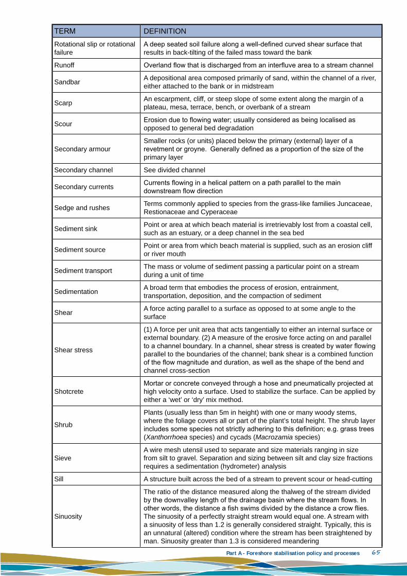
Part A - Foreshore stabilisation policy and processes 65
TERM DEFInITIOn
Rotational slip or rotational failure
A deep seated soil failure along a well-defined curved shear surface that results in back-tilting of the failed mass toward the bank
Runoff Overland flow that is discharged from an interfluve area to a stream channel
Sandbar A depositional area composed primarily of sand, within the channel of a river, either attached to the bank or in midstream
Scarp An escarpment, cliff, or steep slope of some extent along the margin of a plateau, mesa, terrace, bench, or overbank of a stream
Scour Erosion due to flowing water; usually considered as being localised as opposed to general bed degradation
Secondary armourSmaller rocks (or units) placed below the primary (external) layer of a revetment or groyne. generally defined as a proportion of the size of the primary layer
Secondary channel See divided channel
Secondary currents Currents flowing in a helical pattern on a path parallel to the main downstream flow direction
Sedge and rushes Terms commonly applied to species from the grass-like families Juncaceae, Restionaceae and Cyperaceae
Sediment sink Point or area at which beach material is irretrievably lost from a coastal cell, such as an estuary, or a deep channel in the sea bed
Sediment source Point or area from which beach material is supplied, such as an erosion cliff or river mouth
Sediment transport The mass or volume of sediment passing a particular point on a stream during a unit of time
Sedimentation A broad term that embodies the process of erosion, entrainment, transportation, deposition, and the compaction of sediment
Shear A force acting parallel to a surface as opposed to at some angle to the surface
Shear stress
(1) A force per unit area that acts tangentially to either an internal surface or external boundary. (2) A measure of the erosive force acting on and parallel to a channel boundary. In a channel, shear stress is created by water flowing parallel to the boundaries of the channel; bank shear is a combined function of the flow magnitude and duration, as well as the shape of the bend and channel cross-section
ShotcreteMortar or concrete conveyed through a hose and pneumatically projected at high velocity onto a surface. Used to stabilize the surface. Can be applied by either a ‘wet’ or ‘dry’ mix method.
Shrub
Plants (usually less than 5m in height) with one or many woody stems, where the foliage covers all or part of the plant’s total height. The shrub layer includes some species not strictly adhering to this definition; e.g. grass trees (Xanthorrhoea species) and cycads (Macrozamia species)
SieveA wire mesh utensil used to separate and size materials ranging in size from silt to gravel. Separation and sizing between silt and clay size fractions requires a sedimentation (hydrometer) analysis
Sill A structure built across the bed of a stream to prevent scour or head-cutting
Sinuosity
The ratio of the distance measured along the thalweg of the stream divided by the downvalley length of the drainage basin where the stream flows. In other words, the distance a fish swims divided by the distance a crow flies. The sinuosity of a perfectly straight stream would equal one. A stream with a sinuosity of less than 1.2 is generally considered straight. Typically, this is an unnatural (altered) condition where the stream has been straightened by man. Sinuosity greater than 1.3 is considered meandering

Part A - Foreshore stabilisation policy and processes 66
TERM DEFInITIOn
Slide/sliding
Sliding is a method of structure failure that occurs when the whole wall shifts riverward as a result of pressure on the rear wall from soil pressure, surcharge, groundwater and earth loads exceeds the sum of the frictional resistance of the wall base and passive resistance at the toe
Slope
The degree of deviation from horizontal. This may be expressed either as a percentage, as a numerical ratio, in degrees, or as rise or fall per unit distance of stream length. As a percentage, the number of metres of rise or fall in 100m of horizontal distance. As a ratio, it is the number of metres vertical (V) to the number of metres of horizontal (H); e.g. a 25 per cent slope is equal to a 1v:4H slope, is equal to a slope of approximately 14 degrees, and is equal to 0.25m per m. Slope is sometimes described by the phrase ‘the rise over the run’
Slumping
Shallow movement of a soil mass down a streambank as the result of an instability condition at or near the surface. Conditions leading to slumping are: bed degradation, attack at the bank toe, rapid drawdown, and slope erosion to an angle greater than the angle of repose of the material. Sometimes called ‘slope failure’ or ‘sloughing’
Snagging The removal of material that is obstructing the flow of the stream or interfering with navigation
Soft engineering Usually refers to the use of living plant (bioengineering), or combinations of bioengineering and coir fibre rolls or mats for bank protection.
Sorting
(1) In a descriptive sense, the degree of similarity, in respect to some particular characteristic, of the component parts in a mass of material. (2) In reference to size distribution, poorly sorted implies a wide distribution of material sizes. Well-sorted is the opposite of poorly sorted and would describe material of similar size and shape
Spall
(1) The breaking off of chips, fragments, or thin layers of rock due to physical and chemical forces, such as freeze-thaw cycles, weathering, or quarrying and handling operations. (2) A fragment of rock resulting from such forces, sometimes used in the context of riprap gradation specifications
Specific gravityRatio of the mass of any volume of a substance to the mass of an equal volume of water at 4°C. A substance with a specific gravity of less than 1.0 will float; specific gravity greater than 1.0 will sink
SpoilExcess rock or soil material not needed after a project is constructed. Sometimes used in reference to material that has been dredged from a navigation or flood control channel
Stockpiling Sand piled on a beach foreshore to nourish downdrift beaches by natural littoral currents or forces
Storm surge A rise above normal water level on the open coast due to the action of wind stress on the water surface
Stratification(1) The formation, accumulation, or deposition of materials in layers. (2) Two or more horizontal layers of water of differing characteristics, especially the arrangement of the waters of a lake in layers of different densities
Streambank The side slopes of a channel between which the streamflow is confined except during floods
SurchargeWeight or load acting on or near a retaining wall that impacts its ability to perform. Surcharge loads must be included in retaining wall design and engineering

Part A - Foreshore stabilisation policy and processes 67
TERM DEFInITIOn
Survey
A map of the bed, banks, and/or the adjacent floodplain of a stream. Typically, elevations are taken along a series of cross-sections that are roughly perpendicular to the direction of stream flow, although recent innovations in surveying and mapping technology are less restrictive, and may allow more detailed coverage with less field work. Surveys made for special purposes may involve more or less detail or area of coverage, depending upon the specific need
Tensile strength The maximum stress a material will bear when subjected to a stretching load
Thalweg The line connecting the lowest or deepest points along a stream bed in the longitudinal direction
TidesThe periodic rising and falling of the water that results from gravitational attraction of the moon and sun and other astronomical bodies acting upon the rotating earth
Tieback Structure placed between longitudinal protection or longitudinal training works and the bank to prevent flanking
Toe
The break in the slope at the foot of a bank where the bank meets the bed. May not be well-defined; often the bank slope flattens as it nears the toe, and the horizontal location and elevation of the toe at a given location often changes with stream discharge
Toe erosionThe erosion of particles from the streambank and/or bed which results in the undermining of the toe and subsequent gravity collapse or sliding of overlying layers
Top of bank The usually well-defined break at the top of the bank slope, where the flood plain begins
Tree Woody plants with a single trunk and canopy, where the canopy is less than or equal to two-thirds of the height of the trunk
Turbidity The degree of cloudiness in water caused by suspended particles. Turbidity can be measured precisely and is often used as an indicator of pollution
Unconsolidated Friable or loose material lacking internal cohesion
UndercuttingErosion of material at the foot of a cliff or bank, e.g. a sea cliff, or riverbank on the outside of a meander. Ultimately, the overhang collapses and the process is repeated
Updrift The direction opposite that of the predominate movement of littoral materials
Uplift The hydrostatic force of water exerted on or underneath a structure, causing a displacement of the structure
Upper bank The portion of a streambank which is normally above water
Velocity
The speed that water travels in a given direction; expressed as a distance travelled during an interval of time, usually in feet per second (fps) or metres per second (m/s). Theoretically, velocity is a vector, and the value of speed would be accompanied by a precise direction but for practical purposes it is usually assumed to be in the general direction of flow at the time and under the conditions under study
Wale(r)A horizontal component of a fender system generally placed between the vertical fenders and the pier structure and used for horizontal distribution of forces from a vessel
Wall Generally rigid vertical structures installed to retain a higher elevation of foreshore by providing a barrier to the loss of material from the bank
Weeds A non-local species, including plants native to Australia outside their natural distribution
Wind waves Waves generated by a transfer of energy by wind blowing over the water surface

Part A – Foreshore stabilisation policy and processes 68
Table 9.2 List of symbols used
Symbol Represented Measure Unit
d1 Gabion width m
D Particle diameter mm
Df Filter pore size mm
Dn Nominal stone size m
Dn50 Equivalent cube length of median rock
m
FD Drag force Newton (N)
FS Factor of safety in design. To account for assumptions in the design process.
-
G Acceleration due to gravity ms-2
h Depth below the surface m
hw1 Height of groundwater level above toe
m
hw2 Height of free water level above toe
m
hs Height of structure above toe m
hE Depth of earth pressure load above toe
m
H Depth below the surface m
H Design wave height m
HE Earth pressure load Newtons (N)
Hsurcharge Horizontal surcharge Load Newtons (N)
HW Hydrostatic load Newtons (N)
Hw,ground Horizontal hydrostatic load from groundwater surface
Newtons (N)
HW,water Horizontal hydrostatic load from free water surface
Newtons (N)
KA Active earth pressure coefficient -
Kd Damage coefficient corresponding to H
-
Kd Stability coefficient relating to USACE (2006)
-
Ks Stability coefficient -
M Mean grain size mm
M50 Medium mass of rocks Tonnes
Ρs Mass density of rocks t/m3
Ρw Mass density of water kgm-3
RA Renourishment factor -
Sq Specific gravity of rock t/m3
SW Specific gravity of water t/m3
V Gabion volume m3

Part A – Foreshore stabilisation policy and processes 69
Symbol Represented Measure Unit
W Armour size Tonnes
W’ Effective buoyant weight of the gabion
Newtons (N)
α Slope angle °
cotα Revetment slope Radians
∆ (Ρs/ Ρw) - 1 -
φ Standard deviation -
Φb Borrowed material Phi
Φf Soil angle of friction °
Φn Native material Phi
ρ Earth density t/m3
ρw Density of water kgm-3
ρwood Density of the brush mattress kgm-3

Dir
ect
ap
pro
ach
es
Key references (Listed in full in Part A)
Tech
niq
ues
Key references (Listed in full in Part A)
Rush
es a
nd S
edges
• Meney, K.A . & Pate, J.S. (1999)
• Pen, L. J. (1983)
• Pen (1999)
• Powell, R. and Emberton, J. (1996)
• SRT (1997)
• SRT (2008)
• WRC (1997a)
• WRC (1997b)
• WRC (1999)
• WRC (2000a)
• WRC (2001b)
Reveg
eta
tio
n
• Allen et al. (1997)
• Bendell et al. (2006) vegetation controlChen & Cotton (1988) sections on vegetation lining
• Biedenharn (1997) Chapter 9 and Appendix B plus Chapter 12 has information on grade stabilisation, 6.3 has information on toe protection
• DoE (2006) – costs
• DIPNR (2004)
• DPIW (2003) – BMP 7 riparian vegetation
• Fischenich, C. (2001) stability thresholds
• Fischenich (2000) –section on ‘Soil Bioengineering Techniques’
• Fischenich, J. C. (2001) – impacts
• Fischenich, & Allen (2000)
• Fischer & Fischenich (2000)
• Goldsmith et al. (2001) – soil compaction required for plant growth capacity
• LMCC (2004) 5.1.2 and Appendix 1
• McCullah and Gray (2005) • Meney, K.A . & Pate, J.S. (1999)
• Pen, L. J. (1983)
• Pen (1999)
• Powell (1990)
• Powell, R. and Emberton, J. (1996)
• Price, P. and Lovett, S. (2002)
• Rogers et al. (accessed 2008) estuarine revegetation
• Rutherfurd, I.D., Jerie, K. and Marsh N. ,2000
• SRT (1997)
• SRT (2008)
• WRC (1997a)
• WRC (1997b)
• WRC (1999)
• WRC (2000)
• WRC (2000a)
• WRC (2001b)
• WRC (2002a)
Tre
es,
Shru
bs
and H
erbs
• Pen, L. J. (1983)
• Pen (1999)
• Powell (1990)
• Powell, R. and Emberton, J. (1996)
• Rippey, E. & Rowland, B. 1995
• SRT (1997)
• SRT (2008)
• WRC (1997a)
• WRC (1997b)
• WRC (1999)

Dir
ect
ap
pro
ach
es
Key references (Listed in full in Part A)
Tech
niq
ues
Key references (Listed in full in Part A)
• Allen et al. (1997) • Bentrup & Hoag (1998)
• Biedenharn (1997) Chapter 9 and Appendix B plus Chapter 12 has information on grade stabilisation, 6.3 has information on toe protection
• Damara (2007a) – sections on bioengineering
• Davis & Maynord (1998)
• DIPNR (2004) design guidelines 13 and 16 at a general level combined with all vegetation design guideline
Coir logs
• Allen & Fischenich (2000)
• EMRC (2007) Sections 4.3.4 subheading ‘coir logs’
• King et al. (1994) – briefly mentions reed rolls
• McCullah & Gray (2005) ‘coconut fibre rolls’ and ‘slope flattening’
• MDoEWMA (2000) MGWC 2.6 natural fibre rolls
• Muhlberg & Moore (2005a) section on coir logs and costs
• Muhlberg & Moore (2005c)
• Muhlberg & Moore (2008a)
• Muhlberg & Moore (2008b) - costs
• PIANC (1996)
• PIANC (1992)
• Pilarczyk et al. (1998) stability criteria for geosynthetics
• USDA (1996) streambank (650.1601 (d) (4viii)) and shoreline (650.1602 (c) (8))
• WDFW (2004) – chapter 6 (pp 6-149 – 6-156)
• WRC (2001a), River Restoration Manual – Stream Stabilisation Section 4.3 Organic geotextiles
Bio
en
gin
eeri
ng
(w
ith
reveg
eta
tio
n)
• Donat (1995) review of bioeng techniques. Fantastic reference with construction, maintenance, cost, etc
• Fischenich, C. (2001) stability thresholds
• Fischenich, J. C. (2001) – impacts
• Fischenich, & Allen (2000)
• Ghetti & Chanan (2005)
• Goldsmith et al. (2001) – soil compaction required for plant growth capacity
• Lagasse et al. (2001) 4.7 biotechnical engineering
• Pen (1999) 8.4 stream channel management, high level background information
• Richardson et al. (2001) section 6.6.1 and 6.6.2
• Sotir (2008a)
• Sotir (2008c) talks about the benefits and applicability of different bioengineering methods.
• USACE (1992b) soil bearing capacities including at foundations
• USACE (1992) GT-SE-1.5 some information on bioengineering methods
Geo
text
ile m
atting (
oft
en c
alle
d J
ute
mat
ting)
• Caltrans (2003)
• CBBEL (1999) Section 5.11 ‘Practice 1104 erosion control blanket’
• Chen & Cotton (1988) sections on jute, paper or synethetic net along with straw with net
• Davis & Maynord (1998)
• Donat (1995) review of bioeng techniques
• ECTC (2001)
• ECTC (2004)
• EMRC (2007) Sections 4.3.4 subheading ‘matting’
• Fischenich (2000) –section on ‘Geotextile fabrics’
• Honnigford (2003)
• NAVFAC (2004)
• Perry (1998) Section 4 on turf reinforcement mat
• PIANC (1996)
• PIANC (1992)
• Pilarczyk et al. (1998) stability criteria for geosynthetics
• McCullah & Gray (2005) ‘turf reinforcement mats’ and ‘erosion control blankets’ and ‘slope flattening’
• Miljostyrelsen (2003) – root barrier
• Texas DOT (1999) extensive tests of different manufacturers of geotextile mats/channel liners
• USACE (1992) GT-SE-1.5 some information on matting
• USACE (1997b) BMP 36 geotextile matting
• USDA (1991)
• WDFW (2004) Appendix H planting considerations and erosion-control fabric
• WRC (2001a), River Restoration Manual – Stream Stabilisation Section 4.3 Organic geotextiles
• WRC (2002a) – demonstration sites of waterways restoration in WA water note, focus on sites 2, 8, 9, 11

Dir
ect
ap
pro
ach
es
Key references (Listed in full in Part A)
Tech
niq
ues
Key references (Listed in full in Part A)
• USDA (1990) soil structure, useful information on resloping and loading
• USDA (1992a) soil bioengineering
• USDA (1996) streambank (650.1601 (d) (2)) and shoreline (650.1602 (c) (7))
• WDFW (2004) – chapter 6 (pp 6-119 – 6-162) biotechnical techniques
• WLAP (2004a) 7.3 general for streambank and lakeshore stabilisation
Bru
shin
g/B
undlin
g
• CBBEL (1999) Section 5.5 ‘Practice 503 branch packings’
• Donat (1995) review of bioeng techniques
• Ellis et al. (2002) – brush bundling effectiveness on reducing boat wake energy
• EMRC (2007) Sections 4.3.4 subheading ‘brushing’
• King et al. (1994) – briefly mentions brush bundling
• MDoEWMA (2000) MGWC 2.7 brush layering
• Muhlberg & Moore (2005a) section on brush layering and costs
• Muhlberg & Moore (2005b)
• Muhlberg & Moore (2008b) - costs
• Sotir & Fischenich (2001) live and inert fascines
• USDA (1992a) (3) brushlayer (pp 18.22 – 18.24) and (4) branchpacking (pp 18.25 – 18.27)
• USDA (1996) streambank (650.1601 (d) (2iii))
• WRC (2001a), River Restoration Manual – Stream Stabilisation Section 4.2 brushing
Soil
repla
cem
ent
(gra
vel/
sa
nd a
nd s
oil-
cem
ent)
. • Fischenich (2000) –section on ‘soil cement’
• CDOT (2004) Chapter 17 all sections on soil=cement
• Chen & Cotton (1988) sections on gravel
• Lagasse et al. (2001) 6.6.2 rigid revetments case history, Design guideline 2 for soil cement
• Lagasse et al. (1995) small section on soil cement 5.7.2 and 6.6.1
• Perry (1998) Section 2 and 3 on soil cement
• Richardson et al. (2001) discuss this in section 6.6.8 soil-cement
• WDFW (2004) – chapter 6 (pp 6-139-6-148) soil reinforcement
Bru
sh m
attr
essi
ng
• Allen & Fischenich (2001)
• CBBEL (1999) Section 5.5 ‘Practice 505 brush mattress’
• Donat (1995) review of bioeng techniques. Fantastic reference with construction, maintenance, cost, etc
• King et al. (1994) – briefly mentions brush mattressing
• McCullah & Gray (2005) ‘live brush mattressing’ and ‘live brushlayering’
• MDoEWMA (2000) MGWC 2.8 brush mattressing
• Muhlberg & Moore (2005a) section on brush mat and costs
• Muhlberg & Moore (2008b) - costs
• Sotir (2008a) includes some info on brush mattressing
• Sotir (2008d)
• USDA (1996) streambank (650.1601 (d) (2vii)) and shoreline (650.1602 (c) (7iii))

Dir
ect
ap
pro
ach
es
Key references (Listed in full in Part A)
Tech
niq
ues
Key references (Listed in full in Part A)
Bas
kets
(st
epped
and n
ot
incl
ined
)
• Brown (1979)
• CBBEL (1999) Section 5.5 ‘Practice 512 gabion retaining wall’
• EMRC (2007), Section 4.3.4 subheading ‘rock gabions’ and Appendix 13 installation of rock gabions
• Klein Breteler & Pilarczyk (1998)
• McCullah & Gray (2005) ‘vegetated gabion basket’
• PIANC (1992)
• Pilarczyk (1998)
• Richardson et al. (2001) section 6.6.3 rock-and-wire mattress
• WRC (2001a), River Restoration Manual – Stream Stabilisation Section 4.4.2 Rock gabions
• WRC (2002a) - – demonstration sites of waterways restoration in WA water note, focus on sites 12
Gab
ion
s
• Biedenharn et al. (1997) Chapter 6.3 has info on toe protection
• Bretler & Pilarczyk (1998)
• Brown (1979)
• Brown & Clyde (1989) sections on wire-enclosed rock
• CDOT (2004) Chapter 17 all sections on wire-enclosed rock
• Chen & Cotton (1988) sections on wire-enclosed riprap
• Damara (2007a) – sections on gabions • Davis & Maynord (1998) • DIPNR (2004) design guidelines 13 and 16 at a
general level and design guideline 15
• Donat (1995) discusses vegetated gabions
• Fischenich, C. (2001) stability thresholds
• Fischenich (2000) – whole document and section on ‘Gabions’
• Fischenich, J. C. (2001) – impacts
• Fischenich, & Allen (2000)
• Freeman & Fischenich (2000)
• King et al. (1994) – briefly mentions gabions
• Lagasse et al. (2001) 6.6.1 flexible revetment case history
• Lagasse et al. (1995) small mentions in 5.7.1 and 6.6.1 under rock-and-wire baskets (in the revetment section)
• MDoEWMA (2000) MGWC 2.3 gabions
• Pen (1999) 8.4 stream channel management, high level background information
• Racin & Hoover (2001) corrosion of gabions
• Rogers et al. (accessed 2008) estuarine gabions
• USACE (1981) section on ‘revetments’ under heading gabions and ‘selection among available options’. Relevant to estuarine conditions
• USACE (1992b) soil bearing capacities including at foundations
• USACE (1997b) BMP 23 section on gabions
• USDA (1990) soil structure, useful information on resloping and loading
• USDA (1992a) (7) vegetated gabions (pp 18.32 – 18.33)
• USDA (1996) streambank (650.1601 (d) (4xi))
Mat
tres
s
• BAW (2005) section 7.2.5.3 failure mechanism for toe blankets
• Biedenharn (1997) Chapter 7.4.3
• EMRC (2007), Section 4.3.4 subheading ‘rock mattresses’
• Lagasse et al. (2001) Design guideline 3 for wire enclosed riprap mattress
• McCullah & Gray (2005) ‘vegetated gabion mattress’
• PIANC (1992)
• Richardson et al. (2001) section 6.6.4 gabions
• WRC (2001a), River Restoration Manual – Stream Stabilisation Section 4.4.4 Geotextiles, mattresses and flexmats

Dir
ect
ap
pro
ach
es
Key references (Listed in full in Part A)
Tech
niq
ues
Key references (Listed in full in Part A)
• BAW (2005) Hydraulic, geotechnical considerations related to revetments [mainly rock], including failure at toe
• Bendell et al. (2006) sloped structures
• Biedenharn et al. (1997), 5 and 6.3 toe protection
• Bretler & Pilarczyk (1998)
• Brown & Clyde (1989)
• BS 6349-1 2000, Maritime structures. Part 1 useful information on geotech. considerations and loads
• BS 6349-7 1991, Maritime structures. Part 7: Guide to the design and construction of breakwaters translate to revetments
• Damara (2007a) – sections on revetments
Rock
toe
with r
eslo
pin
g
• BAW (2005) Chapters 6–7
• Biedenharn (1997) Chapter 6.3 and 7.1.4 with Chapter 12 having information on grade stabilisation
• EMRC (2007), Section 4.3.4 subheading ‘riprap’ and Appendix 13 – installation of riprap
• Fischenich, C. (2001) stability thresholds
• GCSWCD – SR-08 Riprap
• McCullah & Gray (2005) ‘longitudinal stone toe’
• MDoEWMA (2000) MGWC 2.11 toe protection
• Perry (1998) focuses on levee protection, but also has a whole section (7) on slope instability
• Schor (1980) landform grading
• Shields et al. (1995a) revegetation alone vs with structures
• Shields et al. (1995b) groins and longitudinal stone toe considered
• Smith (1999) toe stability of rubble mound structures
• Sotir & Nunnally (1995) riprap rock toe with bioeng
• WRC (2001a), River Restoration Manual – Stream Stabilisation Section 4.4.3 Rock riprap
• USACE (1990) large rock
• WRC (2002a) - – demonstration sites of waterways restoration in WA water note, focus on sites 3, 5
Revetm
en
ts • Fischenich (2000) – whole
document and section on ‘Stone-fill revetments ’Fischenich, J. C. (2001) – impacts
• Fischenich, & Allen (2000)
• Lagasse et al. (2001) 4.4 riprap and design guideline 8 riprap at piers and abutments, and design guideline 12 revetments
• Lagasse et al. (1995) 5.7.1, 5.7.2 and 6.6.1
• LMCC (2004) 5.2.1 minor comments on revetments
• Gourlay (2004) Supplement D
• Pen (1999) 8.4 stream channel management, high level background information
• Pullen et al. (2007) overtopping considerations
• Richardson et al. (2001) section 6.8 overtopping and specific riprap considerations mentioned under techniques
• Rogers et al. (accessed 2008) estuarine revetments
Tip
ped
rock
• BAW (2005) Chapters 6–7
• Biedenharn (1997) Chapter 7.1 and Appendix A
• Brown & Clyde (1989)
• CBBEL (1999) Section 5.5 ‘Practice 510 stone riprap’
• CDOT (2004) Chapter 17 ‘rock & rubble’ riprap & grouted rock
• Chen & Cotton (1988) sections on riprap
• Davis & Maynord (1998)
• DIPNR (2004) design guidelines 13 and 16 at a general level and design guideline 15
• Fischenich, C. (2001) stability thresholds
• GCSWCD – SR-08 Riprap
• King et al. (1994) – briefly mentions riprap
• Lagasse et al. (2001) 4.4 riprap, 6.6.1 flex. revet case history
• Lagasse et al. (1995) small section on riprap & concreted-grouted riprap in 5.7.1 and 5.7.2 with both in 6.6.1
• McCullah & Gray (2005) ‘vegetated riprap’ and ‘soil and grass covered riprap’
• MDoEWMA (2000) MGWC 2.1 riprap
• Richardson et al. (2001) 6.5 riprap (including design and failure), 6.7 filters, 6.10 stability of riprap, 6.11 filter design
• Shields et al. (1995c) spurs and riprap revetments considered
• Smith (1999) toe stability of rubble mound structures
• Sotir & Nunnally (1995) vegetated riprap
• USACE (1987) GT-RE-1.2 shear-strength rock
• USACE (1990) large rock
• USACE (1991) CO-RR-1.4 and CO-RR-1.5
• USACE (1994) CO-RR-1.3
• USACE (1997b) BMP 19 riprap
• WRC (2001a), River Restoration Manual – Stream Stabilisation Section 4.4.3 Rock riprap

Dir
ect
ap
pro
ach
es
Key references (Listed in full in Part A)
Tech
niq
ues
Key references (Listed in full in Part A)
• SRT 2002a, Policy SRT/DE7—River Retaining Walls
• USACE (1989a) Chapter 5-1 bulkheads, seawalls and revetments
• USACE (1989c) general maintenance of coastal structures in section d. coastal structures
• USACE (1991) CO-RR-1.5
• USACE (1992) GT-SE-1.6 revetments in reservoir shores
• USACE (1992b) soil bearing capacities including at foundations
Inte
rlock
ed r
ock
• CBBEL (1999) Section 5.5 ‘Practice 510 stone riprap’
• Chen & Cotton (1988) sections on riprap
• BAW (2005) Chapters 6–7
• Brown & Clyde (1989)
• CDOT (2004) Chapter 17 all sections on precast concrete blocks
• Fischenich, C. (2001) stability thresholds
• King et al. (1994) – briefly mentions riprap
• Lagasse et al. (2001) 4.4 riprap
• Smith (1999) toe stability of rubble mound structures
• USACE (1981) section on ‘revetments’ and also subheading of stone and ‘selection among available options’. Relevant to estuarine conditions
• USACE (1987) GT-RE-1.2 shear-strength rock
• USACE (1990) large rock
• USACE (1991) CO-RR-1.4 and CO-RR-1.5
• USACE (1994) CO-RR-1.3
• USDA (1996) streambank (650.1601 (d) (4vii)) and shoreline (650.1602 (c) (4)) and Appendix 16A size of riprap
• USACE (1995a) ALL TYPES. Chapter 3 revetments, Appendix B. general design, toe, filter, in Chapter 2. Appendix E has costs, Chapter 6 has enviro impacts
Laye
red • Brown & Clyde (1989)
• USACE (1987) GT-RE-1.2 shear-strength rock
• USACE (1991) CO-RR-1.4 and CO-RR-1.5
• USACE (1994) CO-RR-1.3
• USACE (1996) OM-MS-1.9 monitoring shore perpendicular structures
• USACE (2006) Part VI
• USDA (1990) soil structure, useful information on resloping and loading
• USDA (1996) streambank (650.1601 (d) (4vii)) and shoreline (650.1602 (c) (4)) and Appendix 16A size of riprap
• WDFW (2004) Chap. 6 (pp 6-67 – 6-88) riprap, appendix K lit review of revetments (vague)
• WLAP (2004a) 7.3 general for streambank and lakeshore stabilisation
Cel
lula
r sy
stem
• Boeters et al. (1991)
• Brown & Clyde (1989) sections on pre-cast concrete blocks
• CDOT (2004) Chapter 17 ‘rock and rubble riprap’ and grouted rock
• Davis & Maynord (1998)
• Klein Breteler & Pilarczyk (1998)
• Lagasse et al. (2001) design guideline 4 articulated concrete block
• Perry (1998) Section 2 on cellular confinement system
• Richardson et al. (2001) section 6.6.6 articulated concrete blocks
• USACE (1981) ‘revetments’ under heading concrete blocks and ‘selection among available options’. Relevant to estuarine conditions
• Concrete monitoring: USACE (1996) CS-ES-4.3, USACE CS-MR-1.12 and USACE (1985) CS-ES-1.1 rapid assessment concrete, USACE (1996) OM-MS-1.10
• Concrete maintenance: USACE (1994) CS-MR-1.14, USACE CS-MR-2.1, USACE (1985) CS-MR-3.1, USACE (?) CS-MR-4.4, USACE (1992) CS-MR-7.3, USACE (1996) CS-MR-9.5
• USACE (1995b) Concrete repair
• USDA (1992b) concrete construction
• USDA (1996) streambank (650.1601 (d) (4vii)) with section on concrete block systems
• Vaysburd et al. (1999) concrete maintenance material performance
Blo
ck r
evet
men
t • Biedenharn (1997) Chapter 7.2.1
• MDoEWMA (2000) MGWC 2.2 imbricated riprap
• Perry (1998) Section 2 on concrete block system (may give some indication)
• USACE (1981) section on ‘revetments’ under heading masonry blocks and ‘selection among available options’. Relevant to estuarine conditions

Dir
ect
ap
pro
ach
es
Key references (Listed in full in Part A)
Tech
niq
ues
Key references (Listed in full in Part A)
Flex
mat
• Klein-Breteler & Pilarczyk (1998)
• CDOT (2004) Chapter 17 grouted fabric slope pavement
• Lagasse et al. (2001) 6.6.2 rigid revetments case history and design guideline 5 grout filled mattresses
• Lagasse et al. (1995) small section on concrete filled fabric mat in 5.7.2 and 6.6.1
• WRC (2001a), River Restoration Manual – Stream Stabilisation Section 4.4.4 Geotextiles, mattresses and flexmats
San
d b
ag (
or
concr
ete
fille
d
bag
s)
• Biedenharn (1997) Chapter 7.2.2
• CDOT (2004) Chapter 17 all sections on sand-cement bags
• Lagasse et al. (2001) 6.6.2 rigid revetments case history and design guideline 7 grout /cement filled bags
• Lagasse et al. (1995) small section on sacked concrete in 5.7.2 and 6.6.1
• Richardson et al. (2001) section 6.6.5 sacks
• USACE (1981) section on ‘revetments’ under heading bags, also noted in ‘seawall’ under bags and ‘selection among available options’. Relevant to estuarine conditions
Geo
text
ile
• Bretler & Pilarczyk (1998)
• Caltrans (2003)
• Crowe et al. (1995)
• Davis & Maynord (1998) • DIPNR (2004) design guidelines 13 and 16 at a general level and
design guideline 15
• Fischenich (2000) –section on ‘Geogrid’
• Lagasse et al. (2001) 4.5.3 geotextile containers
• McCullah & Gray (2005) ‘geocellular containment systems and ‘role of geotextiles and natural fabrics—special topic’
• NAVFAC (2004)
• PIANC (1992)
• Pilarczyk et al. (1998) stability criteria for geosynthetics
• USACE (1981) section on ‘seawalls’ under heading longard tubes and ‘selection among available options’. Relevant to estuarine conditions
• USDA (1991)
• WRC (2001a), River Restoration Manual – Stream Stabilisation Section 4.4.4 Geotextiles, mattresses and flexmats

Dir
ect
ap
pro
ach
es
Key references (Listed in full in Part A)
Tech
niq
ues
Key references (Listed in full in Part A)
• BAW (2005) Hydraulic, geotechnical considerations, including failure at toe W
ave
Baf
fles
• Bendell et al. (2006) vertical structures
• Biedenharn (1997), Chapter 5, 6.3 toe protection
• BS 6349-1 2000, Maritime structures. Part 1 useful information on geotech. considerations and loads
• Damara (2007a) – sections on seawalls
• DIPNR (2004) design guidelines 13 and 16 at a general level
• Ebeling et al. (2002) tieback walls
• Fischenich (2000) document and section on ‘Bulkheads’ and ‘Retaining walls’
• Fischenich, J. C. (2001) – impacts
• Fischenich, & Allen (2000)
Tim
ber
wal
ling
• CBBEL (1999) 5.5 ‘Practice 513 timber retaining wall’
• EMRC (2007), Section 4.3.4 subheading ‘log walling’
• Donat (1995) vegetated crib-walls [limited applicability]
• FEMA (2002) Appendix J material durability with a lot of information on timber
• Green Skills (2005) – section 1.4 on materials (timber)
• Lagasse et al. (1995) small section on wood fence in section 6.6.3 could be relevant
• MDoEWMA (2000) MGWC 2.9 live crib [limited applic.]
• Perdok (2002) timber groynes, useful on timber material, life-cycle, construction, maintenance and monitoring.
• Perdok et al. (2003) shorter article on timber groynes
• USACE (1981) section on ‘seawalls’ under headings treated timber and untreated logs, and ‘selection among available options’. Relevant to estuarine conditions
• USACE (1995) Design of Coastal Revetments, Seawalls and Bulkheads. EM 1110-2-1614
• USACE (1996) OM-MS-1.6 monitoring timber dikes
• USDA (1996) shoreline (650.1602 (c) (3)) bulkheads - timber
• WDFW (2004) – chapter 6 (pp6-99 – 6-106) log cribwalls [note may have limited applicability]
• WRC (2001a), River Restoration Manual – Stream Stabilisation Section 4.4.1 Log walling
• Yu & Kao (1989) timber dikes, but could have some relevant info
• Gourlay (2004) Supp. D
• Lagasse et al. (2001) 6.6.3 bulkheads
• Lagasse et al. (1995) bulkheads 5.7.3 and 6.6.5
• LMCC (2004) 5.2.2 minor comments seawalls
• NAVFAC (1998) –designing of bulkheads and seawalls, including loading
San
d b
ag w
alls
(or
concr
ete
fille
d b
ags)
• Biedenharn (1997) Chapter 7.2.2
• CDOT (2004) Chapter 17 all sections on sand-cement bags
• Lagasse et al. (2001) 6.6.2 rigid revetments case history
• Lagasse et al. (1995) small section on sacked concrete in 5.7.2 and 6.6.1
• USACE (1981) ‘seawalls’ under bags and ‘selection among available options’. Relevant to estuarine conditions
• USACE (1985) HY-N-1.1 grout filled bags as sub. for riprap
• USDA (1992b) concrete construction
• NAVFAC (1993) volume II, 5.2.21 inspection of retaining walls and 5.2.27 inspection of waterfronts
• Passe (2000)
Lim
esto
ne
blo
ck
(gra
vity
)
• Standards Australia (2002) AS 4678 Earth Retaining Structures
• USACE (1989) Retaining and Flood Walls. EM 1110-2-2502
Wall
ing
• Pen (1999) 8.4 stream channel management, high level background information
• Pullen et al. (2007) overtopping considerations
Pile
d w
alls
• USACE, NAVFAC & AFCESA (2001) chapter 2 piling and chapter 6 monitoring/evaluation
• USDA (1996) streambank (650.1601 (d) (4iv)) piled revetment

Dir
ect
ap
pro
ach
es
Key references (Listed in full in Part A)
Tech
niq
ues
Key references (Listed in full in Part A)
• Richardson et al. (2001) section 6.4.8 bulkheads and 6.8 overtopping
• Rogers (1981) estuarine bulkheads
• Rogers et al. (acc. 2008) estuarine vertical walls
• SRT 2002a, Policy SRT/DE7—River Retaining Walls
• Strom & Ebeling (2002a; 2002b) tieback (bulkhead) wall design and failure
• USACE (1989a) Chapter 5-1 bulkheads, seawalls and revetments
• USACE (1989b) Floodwalls
• USACE (1989c) general maintenance of coastal structures in section d. coastal structures
• USACE (1991) CO-RR-1.5
Concr
ete
pan
el
• BCMoE (2006) – environmental considerations using concrete
• Brown & Clyde (1989) – sections on concrete pavement
• Bullock & Foltz (1995) for condition of concrete
• CBBEL (1999) Section 5.5 ‘Practice 511 concrete retaining wall’
• CDOT (2004) Chapter 17 all sections on concrete slope protection
• FEMA (2002) Appendix J material durability with some info on reinforced concrete
• Fischenich, C. (2001) stability thresholds
• Lagasse et al. (2001) 6.6.2 rigid revetment case history
• Lagasse et al. (1995) small section on concrete panel revetments in 5.7.2 and 6.6.1
• Concrete monitoring: USACE (1996) CS-ES-4.3, USACE CS-MR-1.12 and USACE (1985) CS-ES-1.1 rapid assessment concrete, USACE (1996) OM-MS-1.10
• Concrete maintenance: USACE (1994) CS-MR-1.14, USACE CS-MR-2.1, USACE (1985) CS-MR-3.1, USACE CS-MR-4.4, USACE (1992) CS-MR-7.3, USACE (1996) CS-MR-9.5
• USACE (1995b) Concrete repair
• USACE (1997b) BMP 23 sections on concrete, grid pavers
• USACE, NAVFAC & AFCESA (2001) chapter 6-3 concrete strength evaluation
• USDA (1992b) concrete construction
• USDA (1996) shoreline (650.1602 (c) (3)) bulkheads – concrete
• Vaysburd et al. (1999) concrete maintenance material performance
• USACE (1992) GT-SE-1.6 some information on seawalls in reservoir shores
• USACE (1992b) soil bearing capacities including at foundations
• USACE (1995a) ALL TYPES. Chapter 4 seawalls and Appendix C, chapter 5 bulkheads and appendix D. general design, toe, filter, in Chapter 2. Appendix E has costs. Chapter 6 has environmental impacts
• USACE (1995b) Seawalls and Bulkheads
• USACE (2006) Part VI
• USDA (1990) soil structure, useful information on resloping and loading
• USDA (1992a) (8) vegetated rock wall (pp 18.34 – 18.35)
• USDA (1996) shoreline (650.1602 (c) (3)) bulkheads
• WLAP (2004a) 7.3 general for streambank and lakeshore stabilisation
• Yeates (2004)
Shee
t-pili
ng
• BAW (2005) 7.2.5.5 failure mechanisms sheet pile wall
• CBBEL (1999) 5.5 ‘Practice 514 sheetpile retaining wall’
• Ebeling et al. (2002) steel sheet-piling tieback walls
• Green Skills (2005) – section 1.4 on materials (steel)
• Griemann & Stecker (1990) – maintenance and repair
• NAVFAC (1998) – a lot of detail on sheet piling and other bulkheads
• USACE (1981) section on ‘seawalls’ under heading sheetpile and ‘selection among available options’. Relevant to estuarine conditions
• USACE (1994) – design of sheet pile walls
• Sheetpile/steel monitoring: USACE (1988) CS-ES-1.4, USACE (1988) CS-ES-1.6, USACE (1988) CS-ES-2.5, USACE (1996) OM-MS-1.4
• USACE, NAVFAC & AFCESA (2001) chapter 2.2.9 steel sheet piling and chapter 5.2 steel corrosion and chapter 6 monitoring/evaluation
• USDA (1992b) metal construction

Ind
irect
ap
pro
ach
es
Key references (Listed in full in Part A) Techniques Key references (Listed in full in Part A)
Without associated structures
• USACE (2006) Coastal Engineering Manual
Combined with hard structures
With sacrificial/ temporary structures
Ren
ou
rish
men
t
• Bendell et al. (2006) beach fill
• BS 6349-5 1991, Maritime structures. Part 5 Dredging and reclamation
• Damara (2007a) – sections on potential reclamation
• Davis & Maynord (1998)
• Fischenich, J. C. (2001) – impacts
• Fischenich, & Allen (2000)
• Gourlay (2004) Supplement A
• Rogers et al. (accessed 2008) estuarine renourishment
• SPM (1984)
• SRT (2001a) policy SRT/DE1 - dredging
• USACE (1981) section on ‘beach fills’ and ‘selection among available options’. Relevant to estuarine conditions
• USACE (1989a) Chapter 4
• USACE (1989c) general maintenance of b. beach berm and foreshore, c. protective dunes
• USACE (1992b) soil bearing capacities
• USACE (2006) Part V Chapter 4
Construction of secondary features

Ind
irect
ap
pro
ach
es
Key references (Listed in full in Part A) Techniques Technique specific relevant references (Listed in full in Part A)
Single short-groyne
Single long-groyne
Headland field
• Silvester & Hsu (1993)
• Ranasinghe & Turner (2006)
Short groyne field
Long groyne field
Gro
yn
es/
Head
lan
ds*
*
• Bendell et al. (2006) groins and breakwaters
• Biedenharn et al. (1997) – Chapter 8 Indirect techniques for erosion protection
• BS 6349-7 1991, Maritime structures. Part 7: Guide to the design and construction of breakwaters may have some useful info that can be translated to groynes
• Damara (2007a) – sections on planform control and groynes
• Donat (1995) – groynes in rivers
• Fischenich (2000) – whole document and section on ‘Flow deflection techniques’, particularly subheading of ‘hardpoints and jetties’
• Fischenich, J. C. (2001) – impacts
• Fischenich, & Allen (2000)
• LMCC (2004) 5.2.3, 5.2.4 minor comments on groynes and breakwaters
• Perdok (2002) timber groynes, but with useful information on groyne design, loads on groynes and beach response
• Perdok et al. (2003) shorter article on timber groynes than Perdok (2002)
• Pirie et al. (2005) – condition and performance rating of nonrubble mound groynes (referred to as jetties). Also has information on failure
• Richardson et al. (2001) discuss this in section 6.4.7 jetties
• Rogers et al. (accessed 2008) ‘groins’
• Shields et al. (1995b) groins and longitudinal stone toe considered
• Smith (1999) toe stability of rubble mound structures
• SRT 2002b, Policy SRT/DE19—Miscellaneous structures with section on groynes
• USACE (1981) section on ‘breakwaters’ and ‘groins’, and ‘selection among available options’. Relevant to estuarine conditions
• USACE (1986) design of breakwaters and jetties (groynes)
• USACE (1989a) Chapter 5-2 jetties and breakwaters, Chapter 5-3 groins
• USACE (1989c) general maintenance of coastal structures in section d. coastal structures
• USACE (1990) large rock
• USACE (1992a)
• USACE (1996) OM-MS-1.5 monitoring groynes
• USACE (1997b) BMP 23 sections on deflection (groins)
• USACE (2006) Part V Chapter 3 (V-3-3-e)
• USDA (1996) streambank (650.1601 (d) (ix stream jetties)) and shoreline (650.1602 (c) (1) groins)
• WDFW (2004) Chapter 6 (pp 6-3 – 6-14) groins
• WRC (2001a), River Restoration Manual – Stream Stabilisation Section 3.4 flow retards and groynes
• Yu & Kao (1989) timber dikes, but could have some relevant info
Geotextile
• McCullah & Gray (2005) ‘role of geotextiles and natural fabrics—special topic’
• NAVFAC (2004)
• Pilarczyk et al. (1998) stability criteria for geosynthetics
• USACE (1981) section on ‘breakwaters’ and ‘groins’, with mention of longard tubes and ‘selection among available options’. Relevant to estuarine conditions
• USDA (1991)

Ind
irect
ap
pro
ach
es
Relevant references (Listed in full in Part A)
Tech
niq
ues
Technique specific relevant references (Listed in full in Part A)
Riffles
• DoE (2006) – costs
• EMRC (2007), Section 4.3.4 subheadings ‘Bed protection and repair’ McCullah & Gray (2005) ‘Newbury rock riffles
• Fischenich & Seal (2000) – boulder clusters
• King et al. (1994) – briefly mentions boulder placement
• MDoEWMA (2000) MGWC 3.9 step pools (best) + MGWC 3.1 boulder placement, MGWC 3.6 log & check dams, MGWC 3.7 weirs, MGWC 3.8 cross vanes
• Shields et al. (1995d) stone weirs
• WRC (2001a), River Restoration Manual – Stream Stabilisation Section 2 on bed control techniques
• WRC (2002a) – demonstration sites of waterways restoration in WA water note, focus on sites 1, 2, 5, 7, 10, 11, 12, 13, 14, 15
Flow
baf
fles
(re
tard
ance
st
ruct
ure
s, s
hore
par
alle
l)
• Fischenich (2000) –section on ‘energy reduction methods’
• Lagasse et al. (2001) 6.6.5 retardance structures case history
• Lagasse et al. (1995) sections on guide banks 5.7.5, 5.7.7, 6.4, 6.6.4
• Richardson et al. (2001) discuss this in section 6.4.10 guide banks
Chan
nel
exc
avation
• BS 6349-5 1991, Maritime structures. Part 5 Dredging and reclamation
• CBBEL (1999) 5.6 ‘Channel excavation/ dredging’ and 5.8 ‘hydraulic dredging’
• Copeland et al. (2001)
• DPIW (2003) – BMP 3 sediment extraction
• GCSWCD – SR-07 Stream channel excavation
• Knighton (1998) – ‘River Channelisation’ pp. 312-316
• Shields et al. (2003)
• Soar & Thorne (2001)
• SRT (2001a) policy SRT/DE1 - dredging
• Watson et al. (1999)
• WDFW (2004) Chapter 6 (pp 6-189 – 6-200) Channel modifications
• WLAP (2004a) 7.2 stream channel maintenance
• WRC (2000c) – sediment in streams water note
• WRC (2002a) - demonstration sites of restoration in WA water note, sites 3, 6
Flo
w m
od
ific
ati
on
• Fischenich, J. C. (2001) – impacts
• Fischenich, & Allen (2000)
• Pen (1999) 8.4 stream channel management, high level background information
• WRC (2001a), River Restoration Manual – Stream Stabilisation Section 2 on bed control techniques and Section 3 on alignment stabilisation techniques
Riv
er t
rain
ing
• CBBEL (1999) Section 5.4 ‘Logjam removal and river restoration’
• Copeland et al. (2001)
• DIPNR (2004)
• King et al. (1994) – brief. removing trees or adding/removing meanders
• Knighton (1998) – ‘River Channelisation’ pp. 312-316
• Lagasse et al. (1995) sections on channel alignments 6.6.6
• Richardson et al. (2001) discuss this in section 6.3 and 6.9.2
• Shields et al. (2003)
• Soar & Thorne (2001)
• Watson et al. (1999)
• WDFW (2004) Chapter 6 (pp 6-189 – 6-200) Channel modifications
• WLAP (2004a) 7.2 stream channel maintenance
• WRC (2002a) – demo. sites of restoration in WA water note, sites 2,6,10,11

Ind
irect
ap
pro
ach
es
Relevant references (Listed in full in Part A)
Tech
niq
ues
Technique specific relevant references (Listed in full in Part A)
Spurs
(sh
ore
per
pen
dic
ula
r)
• Biedenharn (1997) Chapter 8
• Fischenich (2000) –section on ‘Geogrid’
• GCSWCD – SR-01 Rock vanes; SR-02 W-weirs
• Harman & Smith (2000)
• Kuhnle et al. (2002)
• Lagasse et al. (2001) 6.6.4 spurs and Design guideline 1 (bendway weirs/stream barbs, lower elevation but still useful), design guideline 9 spurs
• Lagasse et al. (1995) sections on spurs 5.7.4, 6.3
• MDoEWMA (2000) MGWC 3.3 rock vanes, 3.4 J-hook vanes
• Richardson et al. (2001) section 6.4.1 spurs and 6.4.2 bendway weirs
• Rosgen (2001) J-hook vanes
• Shields et al. (1995c) spurs and riprap revetments considered
• USACE (1992) HY-N-1.8 guidelines for dike spacing
• USACE (1996) OM-MS-1.9 monitoring shore perpendicular structures
• USDA (1996) streambank (650.1601 (d) (4x stream barbs))
• WDFW (2004) Chapter 6 (pp 6-23 – 6-30) barbs
• Yu & Kao (1989) timber dikes, but could have some relevant info
Sill
s
• Bendell et al. (2006) sills
• Broome et al. (1992)
• Davis & Maynord (1998)
• LMCC (2004) 5.2.5. minor comment on sills
• Rogers et al. (accessed 2008) sills
• USACE (1981) section on ‘perched beaches’ and ‘selection among available options’. Relevant to estuarine conditions
• USACE (1992) GT-SE-1.5 some information on sills
• USACE (1992) GT-SE-1.6 some information on sills

Ind
irect
ap
pro
ach
es
Relevant references (Listed in full in Part A)
Tech
niq
ues
Technique specific relevant references (Listed in full in Part A)
Larg
e w
oody
deb
ris
• Cederholm et al. (1997) - Placement
• D'Aoust & Millar (2000) – stability • DIPNR (2004) design guidelines 13 and 16 at a general level and design
guideline 12 for LWD
• DoE (2006) – costs
• DPIW (2003) – BMP 6 managing LWD
• EMRC (2007) Sections 4.3.4 subheading ‘large woody debris (LWD)’ and ‘Using Large woody debris to build riffles’
• Fischenich (2000) –document and section on ‘Tree Revetments and rootwads’
• Fischenich & Morrow (2000)
• Frissel & Nawa (1992) – failure
• GCSWCD – SR-04 Rootwads
• Harman & Smith (2000)
• Hilderbrand et al. (1998)
• King et al. (1994) – appropriateness of rootwads
• Maryland DoE WMA (2000) – sections on rootwads, log vanes and log dams
• McCullah & Gray (2005) ‘Large woody debris structures’ and special topic on sources, species and durability of large wood
• MDoEWMA (2000) MGWC 2.10 root wads and MGWC 3.2 log vanes and MGWC 3.5 stream deflectors
• Muhlberg & Moore (2005a) – rootwads and costs
• Muhlberg & Moore (2008b) - costs
• Shields & Cooper (2000) – LWD for in-channel sediment control
• Shields, Cooper, Knight & Testa (2000) – Design of LWD for incised channels
• Shields, Morin & Cooper (2001a) – Design of LWD
• Shields, Morin & Cooper (2004) – LWD for sand bed channels
• Sotir (2008b) – criteria
• Sylte & Fischenich (2000) – rootwad composites
• USDA (1996) – information included about rootwads and tree revetments including construction notes
• Watson et al (1999) – section 4.2.1 snagging and clearing
• WDFW (2003) – Chapter 6 (Sections on Barbs, Engineered Log Jams, Drop Structures, Roughness Trees, Log Toes, anchor points, Floodplain Roughness), Appendix I ‘Anchoring and placement of large woody debris’, Appendix L ‘Costs’
• WRC (2000b; d and e) – Water Notes, three separate ones on the value, importance, management and placement of LWD
• WRC (2001a), River Restoration Manual – Stream Stab. Sections 2.1 and 3.3
• WRC (2002a) -demo sites of restoration in WA water note, sites 4, 5, 9, 13