Embed Size (px)
Citation preview
Best Practice Catalog
Generator
Revision 2.0, 8/06/2012

HAP – Best Practice Catalog – Generator
Rev. 2.0, 8/06/2012 2
Prepared by
MESA ASSOCIATES, INC.
Chattanooga, TN 37402
and
OAK RIDGE NATIONAL LABORATORY
Oak Ridge, Tennessee 37831-6283
managed by
UT-BATTELLE, LLC for the
U.S. DEPARTMENT OF ENERGY
under contract DE-AC05-00OR22725
HAP – Best Practice Catalog – Generator
Rev. 2.0, 8/06/2012 3
Contents 1.0 Scope and Purpose .....................................................................................................4
1.1 Hydropower Taxonomy Position ............................................................................4
1.1.1 GeneratorComponents ........................................................................................4
1.2 Summary of Best Practices................................................................................... 15
1.2.1 Performance/Efficiency & Capability – Oriented Best Practices ....................... 15
1.2.2 Reliability/Operations & Maintenance Oriented Best Practices ......................... 16
1.3 Best Practice Cross-references ............................................................................. 17
2.0 Technology Design Summary .................................................................................. 18
2.1 Material and Design Technology Evolution ......................................................... 18
2.2 State of the Art Technology ................................................................................. 18
3.0 Operation and Maintenance Practices ...................................................................... 21
3.1 Condition Assessment .......................................................................................... 21
3.2 Operations ........................................................................................................... 22
3.3 Maintenance ........................................................................................................ 23
4.0 Metrics, Monitoring and Analysis ............................................................................ 25
4.1 Measures of Performance, Condition, and Reliability ........................................... 25
4.2 Data Analysis ....................................................................................................... 26
4.3 Integrated Improvements...................................................................................... 26
5.0 Information Sources ................................................................................................ 27
HAP – Best Practice Catalog – Generator
Rev. 2.0, 8/06/2012 4
1.0 Scope and Purpose
The best practice for the electrical generator addresses its technology, condition assessment,
operations, and maintenance best practices with the objective to maximize the unit performance
and reliability. The primary purpose of the generator is to covert the mechanical torque supplied
by the turbine to electrical power.
The manner in which the generator is designed, operated, and maintained provides significant impact to the efficiency, performance, and reliability of a hydropower unit.
1.1 Hydropower Taxonomy Position
Hydropower Facility → Powertrain Equipment → Generator
1.1.1 Generator Components
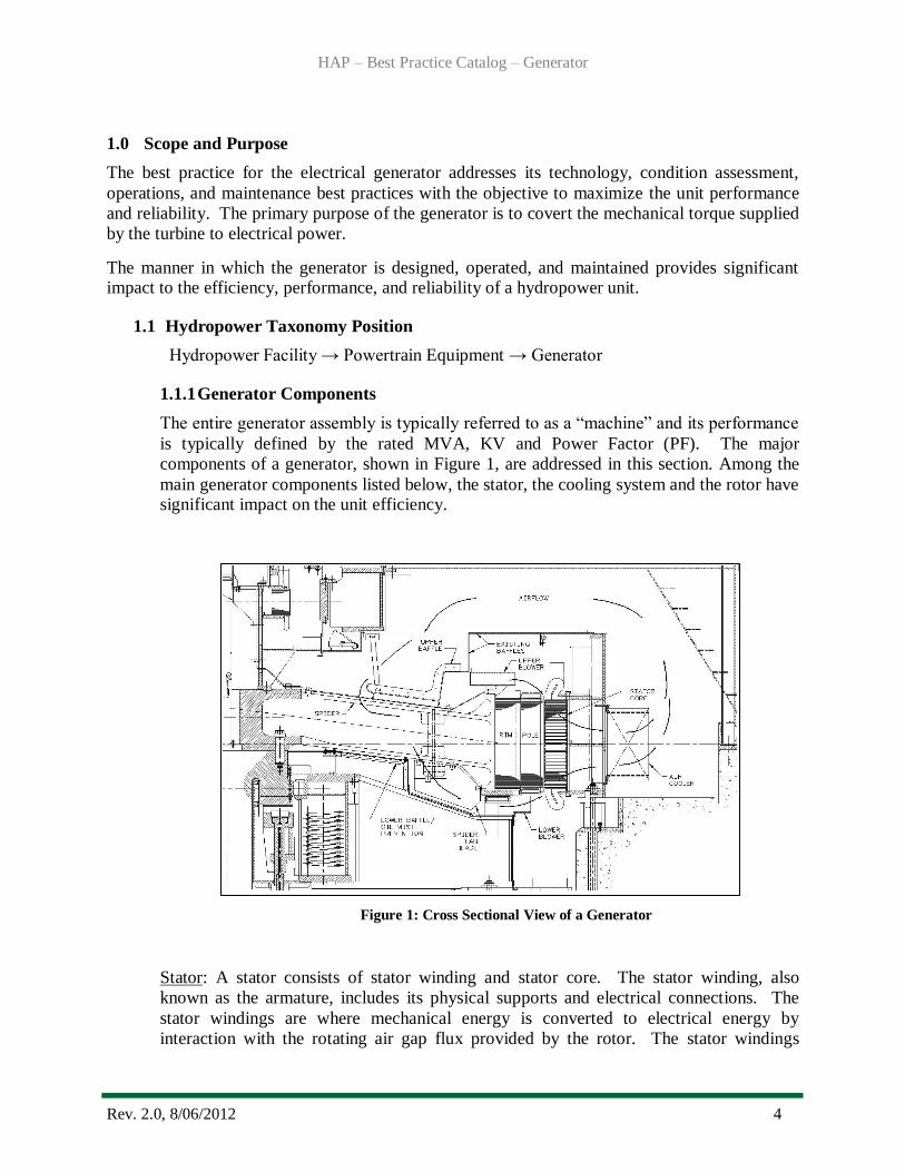
The entire generator assembly is typically referred to as a “machine” and its performance
is typically defined by the rated MVA, KV and Power Factor (PF). The major
components of a generator, shown in Figure 1, are addressed in this section. Among the
main generator components listed below, the stator, the cooling system and the rotor have significant impact on the unit efficiency.
Figure 1: Cross Sectional View of a Generator
Stator: A stator consists of stator winding and stator core. The stator winding, also
known as the armature, includes its physical supports and electrical connections. The
stator windings are where mechanical energy is converted to electrical energy by
interaction with the rotating air gap flux provided by the rotor. The stator windings
HAP – Best Practice Catalog – Generator
Rev. 2.0, 8/06/2012 5
(sometimes referred to as “bars” or “coils”) are comprised of electrically insulated copper
conductors connected such that the design voltage and power requirements are achieved.
The stator winding insulation functions to withstand voltage without failure and is one of
the most critical subcomponents affecting reliability. The copper conductor cross section
and material and the electrical span of the coils have a direct influence on the stator
copper losses. These stator windings are recessed in and supported by the slots formed by
assembly of the laminated core. The stator core provides primary support of the straight
portion of the stator winding. The core also provides the magnetic circuit’s path essential
for the generation of a voltage with the resultant power flow through the winding. The
core is comprised of a stack of thin laminations of highly permeable steel in order to
reduce core losses. Each lamination has a thin coating of insulating varnish that
electrically insulates it from the adjacent lamination to reduce eddy current losses in the
core.
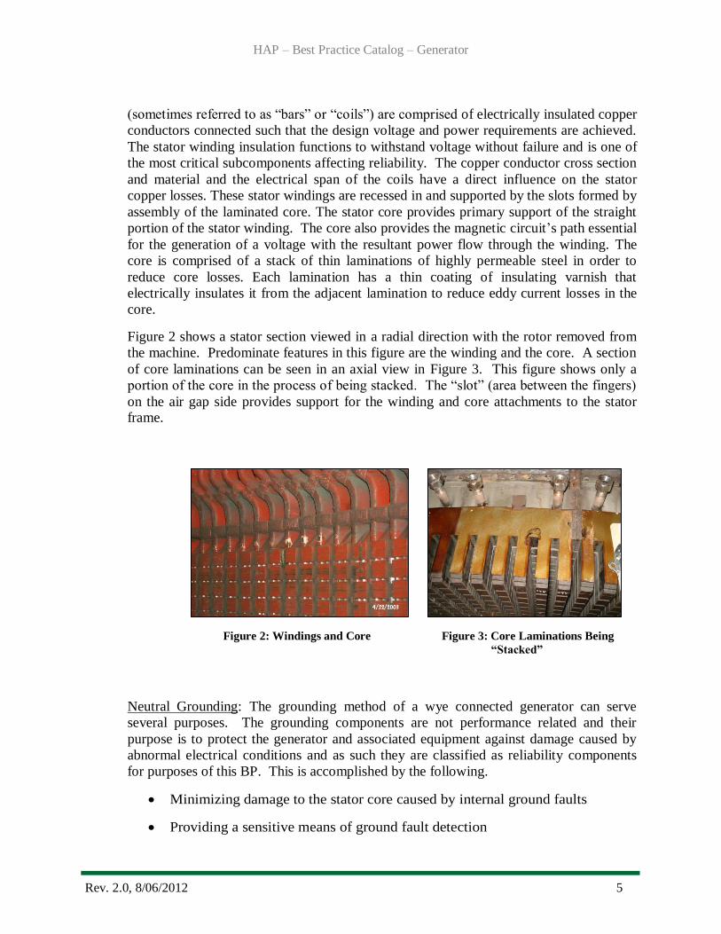
Figure 2 shows a stator section viewed in a radial direction with the rotor removed from
the machine. Predominate features in this figure are the winding and the core. A section
of core laminations can be seen in an axial view in Figure 3. This figure shows only a
portion of the core in the process of being stacked. The “slot” (area between the fingers)
on the air gap side provides support for the winding and core attachments to the stator frame.
Figure 2: Windings and Core Figure 3: Core Laminations Being
“Stacked”
Neutral Grounding: The grounding method of a wye connected generator can serve
several purposes. The grounding components are not performance related and their
purpose is to protect the generator and associated equipment against damage caused by
abnormal electrical conditions and as such they are classified as reliability components
for purposes of this BP. This is accomplished by the following.
Minimizing damage to the stator core caused by internal ground faults
Providing a sensitive means of ground fault detection
HAP – Best Practice Catalog – Generator
Rev. 2.0, 8/06/2012 6
Limiting transient overvoltage stress on generator stator insulation and
Limiting mechanical stress on the generator for external ground faults
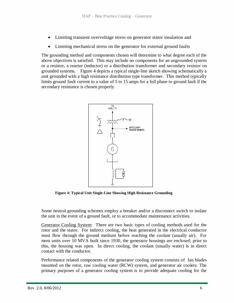
The grounding method and components chosen will determine to what degree each of the
above objectives is satisfied. This may include no components for an ungrounded system
or a resistor, a reactor (inductor) or a distribution transformer and secondary resistor on
grounded systems. Figure 4 depicts a typical single-line sketch showing schematically a
unit grounded with a high resistance distribution type transformer. This method typically
limits ground fault current to a value of 5 to 15 amps for a full phase to ground fault if the secondary resistance is chosen properly.
Figure 4: Typical Unit Single-Line Showing High Resistance Grounding
Some neutral grounding schemes employ a breaker and/or a disconnect switch to isolate
the unit in the event of a ground fault, or to accommodate maintenance activities.
Generator Cooling System: There are two basic types of cooling methods used for the
rotor and the stator. For indirect cooling, the heat generated in the electrical conductor
must flow through the ground medium before reaching the coolant (usually air). For
most units over 10 MVA built since 1930, the generator housings are enclosed; prior to
this, the housing was open. In direct cooling, the coolant (usually water) is in direct contact with the conductor.
Performance related components of the generator cooling system consists of fan blades
mounted on the rotor, raw cooling water (RCW) system, and generator air coolers. The
primary purposes of a generator cooling system is to provide adequate cooling for the
HAP – Best Practice Catalog – Generator
Rev. 2.0, 8/06/2012 7
SPIDER ROTORRIM
Upper Fan
ROTORPOLES
Lower Fan
STATORCORE
STATORFRAME C
oo
ler
Qft
Qrt
Qpt Qt
Qb
Qtot
Qst
Qyt
Qyb
Qsb
Qpb
Qrb
Qsit Qsot
Qsib Qsob
Qfb
stator/field winding insulation material and limit thermal stresses to acceptable levels.
The excitation system may be cooled by the generator air coolers or with ambient air
depending on the design. This will reasonably ensure an acceptable life of the field and stator insulation including the rotating excitations system (if used).
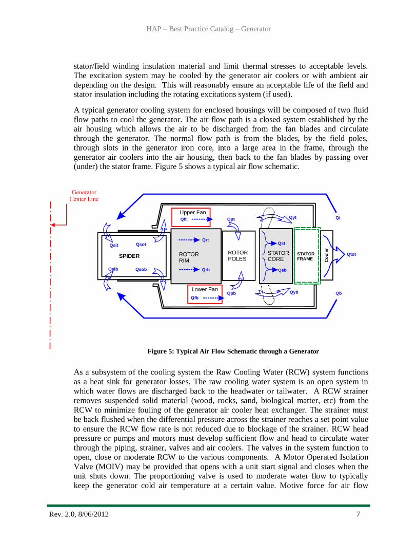
A typical generator cooling system for enclosed housings will be composed of two fluid
flow paths to cool the generator. The air flow path is a closed system established by the
air housing which allows the air to be discharged from the fan blades and circulate
through the generator. The normal flow path is from the blades, by the field poles,
through slots in the generator iron core, into a large area in the frame, through the
generator air coolers into the air housing, then back to the fan blades by passing over (under) the stator frame. Figure 5 shows a typical air flow schematic.
Figure 5: Typical Air Flow Schematic through a Generator
As a subsystem of the cooling system the Raw Cooling Water (RCW) system functions
as a heat sink for generator losses. The raw cooling water system is an open system in
which water flows are discharged back to the headwater or tailwater. A RCW strainer
removes suspended solid material (wood, rocks, sand, biological matter, etc) from the
RCW to minimize fouling of the generator air cooler heat exchanger. The strainer must
be back flushed when the differential pressure across the strainer reaches a set point value
to ensure the RCW flow rate is not reduced due to blockage of the strainer. RCW head
pressure or pumps and motors must develop sufficient flow and head to circulate water
through the piping, strainer, valves and air coolers. The valves in the system function to
open, close or moderate RCW to the various components. A Motor Operated Isolation
Valve (MOIV) may be provided that opens with a unit start signal and closes when the
unit shuts down. The proportioning valve is used to moderate water flow to typically
keep the generator cold air temperature at a certain value. Motive force for air flow
Generator Center Line
HAP – Best Practice Catalog – Generator
Rev. 2.0, 8/06/2012 8
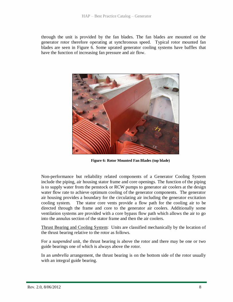
through the unit is provided by the fan blades. The fan blades are mounted on the
generator rotor therefore operating at synchronous speed. Typical rotor mounted fan
blades are seen in Figure 6. Some uprated generator cooling systems have baffles that have the function of increasing fan pressure and air flow.
Figure 6: Rotor Mounted Fan Blades (top blade)
Non-performance but reliability related components of a Generator Cooling System
include the piping, air housing stator frame and core openings. The function of the piping
is to supply water from the penstock or RCW pumps to generator air coolers at the design
water flow rate to achieve optimum cooling of the generator components. The generator
air housing provides a boundary for the circulating air including the generator excitation
cooling system. The stator core vents provide a flow path for the cooling air to be
directed through the frame and core to the generator air coolers. Additionally some
ventilation systems are provided with a core bypass flow path which allows the air to go into the annulus section of the stator frame and then the air coolers.
Thrust Bearing and Cooling System: Units are classified mechanically by the location of
the thrust bearing relative to the rotor as follows.
For a suspended unit, the thrust bearing is above the rotor and there may be one or two guide bearings one of which is always above the rotor.
In an umbrella arrangement, the thrust bearing is on the bottom side of the rotor usually
with an integral guide bearing.

HAP – Best Practice Catalog – Generator
Rev. 2.0, 8/06/2012 9
The modified umbrella type generator locates the thrust bearing on the bottom side of the rotor with a guide bearing both top and bottom.
The purpose of the thrust bearing is to provide axial static and dynamic support of the
unit. Performance and reliability related components of a generator thrust bearing consist
of the thrust pot configuration, oil baffles, oil with specification, bearing adjustment
hardware, and coolers. While there are numerous bearing designs, the basic performance
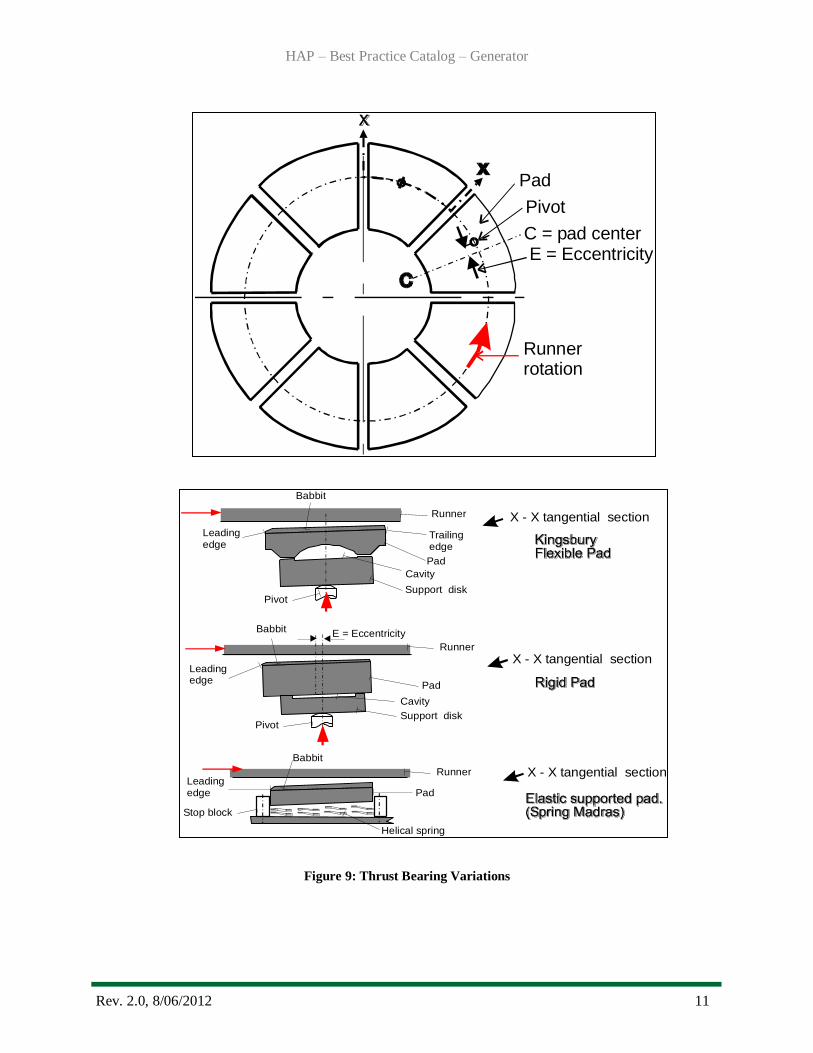
of the thrust bearing is the same. Figures 7 and 8 illustrate common designs. Figure 9
provides a comparison of variant designs. Basic theory is well developed and the
Kingsbury type bearing is typically a preferred design so it will be used for the following
discussion.
Figure 7: Typical Thrust Bearing Assembly
HAP – Best Practice Catalog – Generator
Rev. 2.0, 8/06/2012 10
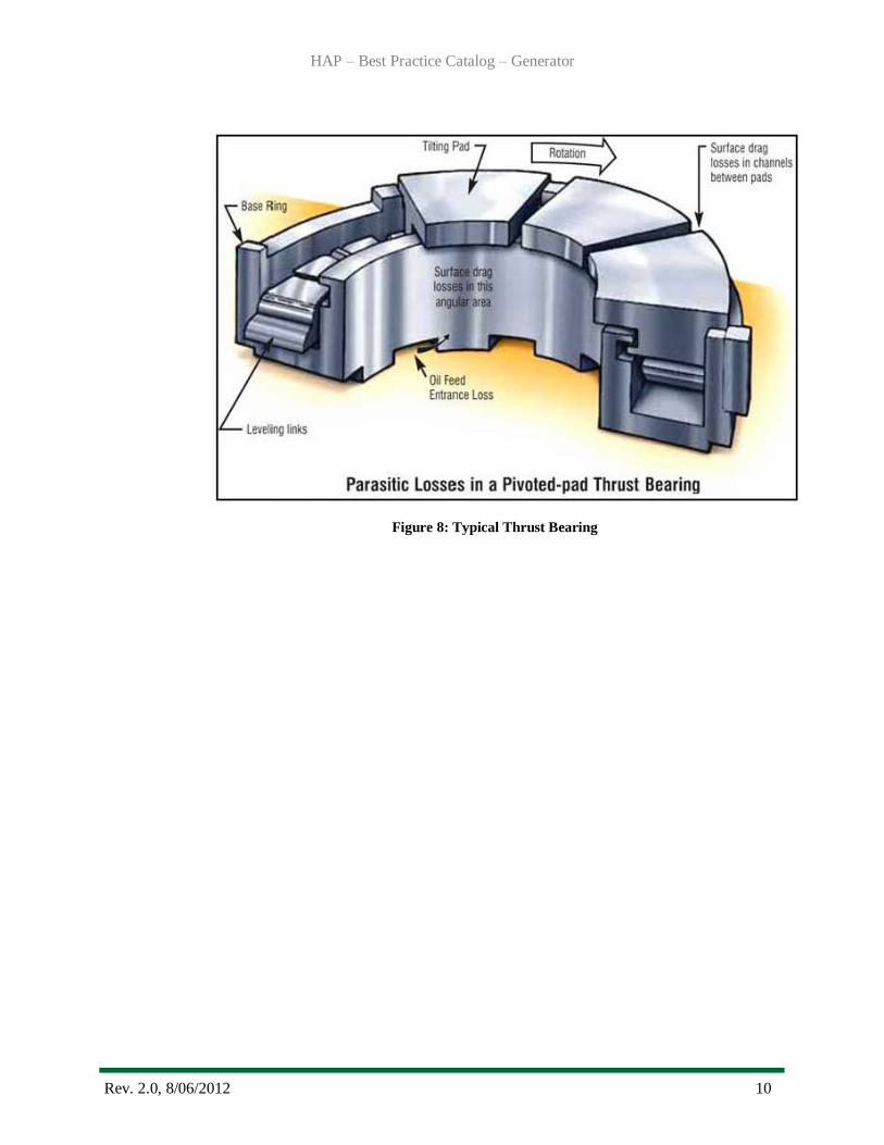
Figure 8: Typical Thrust Bearing
HAP – Best Practice Catalog – Generator
Rev. 2.0, 8/06/2012 11
C = pad center
Pivot
Pad
E = Eccentricity
Runnerrotation
Figure 9: Thrust Bearing Variations
Leadingedge
Leadingedge
Leadingedge
Babbit
Babbit
Babbit
Trailingedge
Pad
Pad
Pad
Support disk
Support disk
Pivot
Pivot
Runner
Runner
Runner
Cavity
Cavity
E = Eccentricity
Helical spring
Stop block
X - X tangential section
X - X tangential section
X - X tangential section
HAP – Best Practice Catalog – Generator
Rev. 2.0, 8/06/2012 12
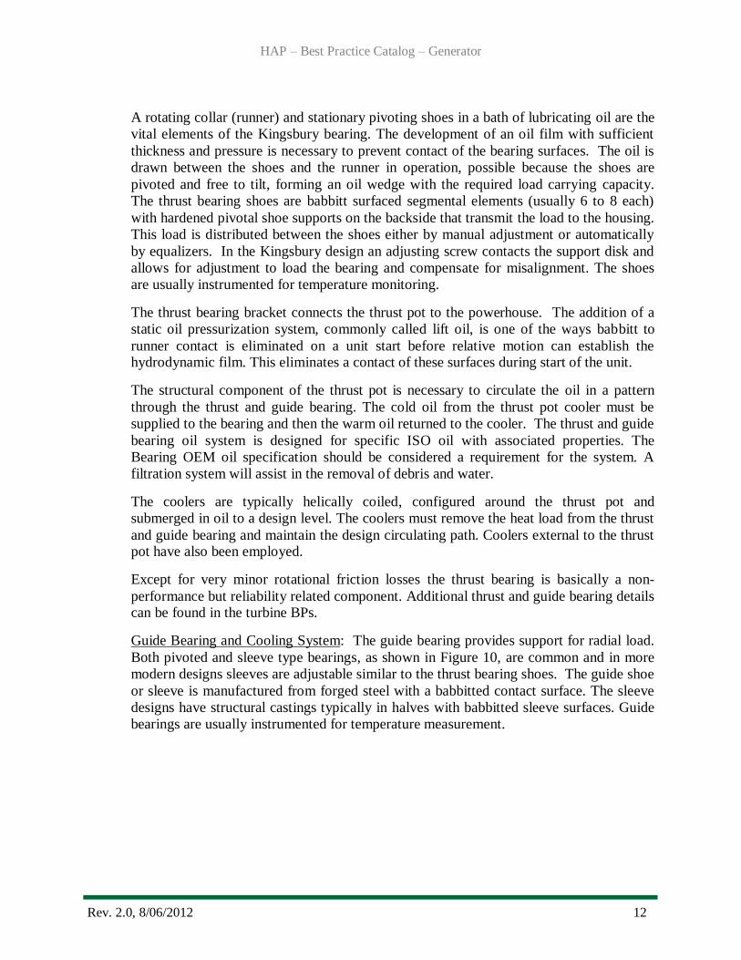
A rotating collar (runner) and stationary pivoting shoes in a bath of lubricating oil are the
vital elements of the Kingsbury bearing. The development of an oil film with sufficient
thickness and pressure is necessary to prevent contact of the bearing surfaces. The oil is
drawn between the shoes and the runner in operation, possible because the shoes are
pivoted and free to tilt, forming an oil wedge with the required load carrying capacity.
The thrust bearing shoes are babbitt surfaced segmental elements (usually 6 to 8 each)
with hardened pivotal shoe supports on the backside that transmit the load to the housing.
This load is distributed between the shoes either by manual adjustment or automatically
by equalizers. In the Kingsbury design an adjusting screw contacts the support disk and
allows for adjustment to load the bearing and compensate for misalignment. The shoes
are usually instrumented for temperature monitoring.
The thrust bearing bracket connects the thrust pot to the powerhouse. The addition of a
static oil pressurization system, commonly called lift oil, is one of the ways babbitt to
runner contact is eliminated on a unit start before relative motion can establish the hydrodynamic film. This eliminates a contact of these surfaces during start of the unit.
The structural component of the thrust pot is necessary to circulate the oil in a pattern
through the thrust and guide bearing. The cold oil from the thrust pot cooler must be
supplied to the bearing and then the warm oil returned to the cooler. The thrust and guide
bearing oil system is designed for specific ISO oil with associated properties. The
Bearing OEM oil specification should be considered a requirement for the system. A
filtration system will assist in the removal of debris and water.
The coolers are typically helically coiled, configured around the thrust pot and
submerged in oil to a design level. The coolers must remove the heat load from the thrust
and guide bearing and maintain the design circulating path. Coolers external to the thrust pot have also been employed.
Except for very minor rotational friction losses the thrust bearing is basically a non-
performance but reliability related component. Additional thrust and guide bearing details can be found in the turbine BPs.
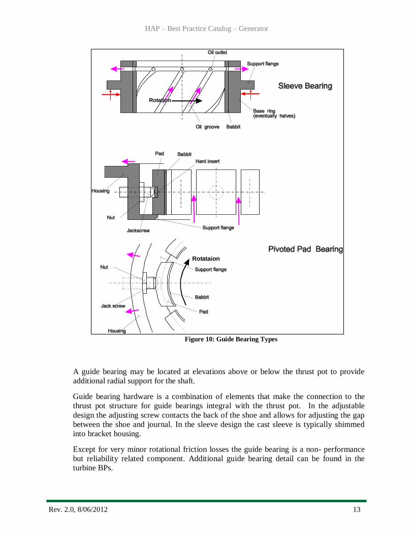
Guide Bearing and Cooling System: The guide bearing provides support for radial load.
Both pivoted and sleeve type bearings, as shown in Figure 10, are common and in more
modern designs sleeves are adjustable similar to the thrust bearing shoes. The guide shoe
or sleeve is manufactured from forged steel with a babbitted contact surface. The sleeve
designs have structural castings typically in halves with babbitted sleeve surfaces. Guide
bearings are usually instrumented for temperature measurement.
HAP – Best Practice Catalog – Generator
Rev. 2.0, 8/06/2012 13
Figure 10: Guide Bearing Types
A guide bearing may be located at elevations above or below the thrust pot to provide
additional radial support for the shaft.
Guide bearing hardware is a combination of elements that make the connection to the
thrust pot structure for guide bearings integral with the thrust pot. In the adjustable
design the adjusting screw contacts the back of the shoe and allows for adjusting the gap
between the shoe and journal. In the sleeve design the cast sleeve is typically shimmed
into bracket housing.
Except for very minor rotational friction losses the guide bearing is a non- performance
but reliability related component. Additional guide bearing detail can be found in the
turbine BPs.
Rotataion
Rotation
HAP – Best Practice Catalog – Generator
Rev. 2.0, 8/06/2012 14
Generator Shaft: The primary function of the shaft is to transmit the torque delivered by
the turbine to rotate the generator rotor so that this power may be converted to electrical
energy. The Generator Shaft must effectively make all the mechanical connections for
the various attached components and carry all loads without unacceptable vibration. The
operational torque (power input) to the shaft, rotating components dead weight, turbine
unbalanced hydraulic thrust and the unbalanced magnetic pull of the generator must be
structurally carried by the generator shaft.
Shafts may be a single piece manufactured from forged steel but some of large shafts can be fabricated.
The connection of the turbine shaft to the generator shaft is made with a bolted
connection. Alignment/fitting up of the generator and turbine shafts, attachments and
assemblies is necessary to create and maintain air gap, turbine clearances and bearing
loading.
Generator shaft hardware is typically a combination of studs/bolts/keys and dowels that make the assembly and their connection to the generator shaft.
Also it should be noted the generator shaft may have a rotating exciter mounted on top of
the generator rotor which provides excitation current and voltage to the field poles.
Typically a Permanent Magnet Generator (PMG) is attached to the top of the rotating
exciter. The details refer to Exciter Best Practice.
The generator shaft is a non-performance but a reliability related component of the generator.
Generator Rotor: The primary function of generator rotor is to carry the field poles
necessary for excitation of the stator winding. The generator rotor must effectively
make all the mechanical connections for the various attached components and carry all
loads without creating unacceptable vibration. The operational torque (power input) to
the rotor, centrifugal loads created by the mass of the rotor components and other rotating
components (dead weight, rim shrink), and the unbalanced magnetic pull of the generator must be structurally carried by the generator rotor.
The structural part of the rotor assembly is typically a cast structure, sometimes called a
spider, machined to allow bolting/keying to the generator shaft at the center and the rotor rim to be installed on the arms with keys.
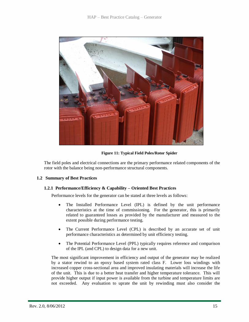
The rotor rim assembly is a laminated cylindrical structure that stacks on a horizontal
machined surface at the end of the spider arm. The rim is typically shrunk on shrink keys
that that may also transmit the operational torque to the generator. The poles consist of
copper windings that are electrically insulated between turns and establish the electrical
circuit which provides the rotor flux for the air gap. Excitation current is provided to the
field poles by the field leads mounted on the rotor arm which are electrically and
mechanically connect to the collector (slip) rings. The field poles are electrically
connected in series. Figure 11 shows typical field poles mounted on the rotor.
HAP – Best Practice Catalog – Generator
Rev. 2.0, 8/06/2012 15
Figure 11: Typical Field Poles/Rotor Spider
The field poles and electrical connections are the primary performance related components of the rotor with the balance being non-performance structural components.
1.2 Summary of Best Practices
1.2.1 Performance/Efficiency & Capability – Oriented Best Practices
Performance levels for the generator can be stated at three levels as follows:
The Installed Performance Level (IPL) is defined by the unit performance
characteristics at the time of commissioning. For the generator, this is primarily related to guaranteed losses as provided by the manufacturer and measured to the
extent possible during performance testing.
The Current Performance Level (CPL) is described by an accurate set of unit
performance characteristics as determined by unit efficiency testing.
The Potential Performance Level (PPL) typically requires reference and comparison
of the IPL (and CPL) to design data for a new unit.
The most significant improvement in efficiency and output of the generator may be realized by a stator rewind to an epoxy based system rated class F. Lower loss windings with
increased copper cross-sectional area and improved insulating materials will increase the life
of the unit. This is due to a better heat transfer and higher temperature tolerance. This will provide higher output if input power is available from the turbine and temperature limits are
not exceeded. Any evaluation to uprate the unit by rewinding must also consider the
HAP – Best Practice Catalog – Generator
Rev. 2.0, 8/06/2012 16
generator structural components, including the core, to ensure that these components can
withstand the additional torques and stresses associated with the increase in power.
In general, modern dielectrics will allow for the use of more copper and less insulation in a
given cross section. The additional copper reduces losses (improves efficiency) but the reduction in insulation thickness increases the volts/mil dielectric stress and could challenge
reliability. In addition, any improvement of one components capacity should also consider the
ability of other components to support this increase or reliability will be adversely affected. An engineering evaluation must be performed to evaluate the effect of increased forces and
currents on existing components not being modified to support the upgrade.
Provide clear temperature limits to operating personnel and/or for automatic control system
programs for setting alarm (i.e., trip temperatures) for the generator.
Trending of stator, field and hot/cold air temperatures will establish accurate performance of
current generator cooling system. Limited IEEE 115 test can provide high quality data and
establish the CPL parameters.
Stator winding temperature limits should be continually monitored. Any trends indicating
increased operating temperatures for the same load and ambient conditions should be investigated for issues with the cooling system.
Periodic comparison of the CPL to the IPL to detect and mitigate degradation that may
impact efficiency or capacity is recommended. As well as, periodic comparison of the CPL
to the PPL to trigger feasibility studies for major upgrades.
1.2.2 Reliability/Operations & Maintenance Oriented Best Practices
Monitor generator temperatures under operating conditions of load and cooling.
Increasing temperatures under these conditions may be indicative of dirt and dust
contamination. Dust and dirt will impede heat transfer characteristics, block cooling flow
passages, and degrade electrical insulation. Cleaning of generator windings and air slots to remove oil, dirt, and debris will improve the heat transfer coefficient of those
components. Cleaning of the core slots in machines with an unusually large amount of
blockage may result in improvements of 5°C to 10°C. The preferred cleaning method is to vacuum rather than to blow debris unless it is reasonably assured that the dislodged
debris will not simply be relocated in the unit. Dry compressed air may be used in areas
not accessible to vacuum cleaning. Oil and other solvent based contaminates will attract
and capture dirt and debris and should be removed by approved solvent cleaning, and the source of the contamination, i.e. oil leak, should be repaired.
The generator air cooler tubes require periodic cleaning to maintain acceptable heat
transfer performance. A major problem in generator air cooler manufacture was the baffles that created an effective heat transfer flow path for the RCW becoming totally
degraded or lost, resulting in a heat exchanger with poor performance. Repairs to the
coolers may correct some of the problems with degraded coolers.
A reduction in the air temperature of the generator air cooler by 5°C is common by
cleaning fouled coolers. Efficient coolers will have a cold air discharge temperature of
approximately 5°C above the RCW inlet temperature. In the case of badly fouled tubes and degraded fins, the air discharge temperature may be 15°C to 20°C higher than the
RCW.
HAP – Best Practice Catalog – Generator
Rev. 2.0, 8/06/2012 17
RCW strainer performance is typically judged by the differential pressure across the
strainer which is improved by a well-designed back flush system that maintains design
RCW flow rates.
The use of proportioning valves may limit thermal cycling of the generator based on cold
air temperature. .
RCW piping leaks due to wall corrosion will degrade cooling system performance.
Leaks of this nature are generally corrected by replacing the section(s) of pipe affected.
Leaks inside the unit air housing should be corrected promptly to prevent water
contamination of electrical or structural components in the housing.
While overall age is a factor, units cycled frequently are subject to increased thermal
stresses that ultimately affect total generation. Likewise, units operated outside their capability curves by exceeding recommended temperatures, will have increased losses,
reduced time to failure, and consequently reduced total generation. Cyclic operations and
operations outside the recommended limits should be minimized.
Shaft vibration should be monitored. Levels of shaft vibration that reach alarm or trip
levels will obviously impact operations, and maintenance will be required in this case.
IEEE 492 Section 7.9 addresses “Vibration Detection and Correction”. Acceptable vibration and Shaft Run out are indicated in Section 8.3.7.1 and it is noted “No standards
for acceptable maximum vibration have been developed “. This is partly due to the fact
that there are numerous machine designs with different generator thrust and guide
bearings and likewise for the turbine guide bearings. Develop root cause of vibration problems and schedule maintenance repairs or modification.
Monitor bearing temperatures to alarm and trip when recommended temperature limits
are exceeded. Multiple shoes of each bearing should be monitored to preclude the
possibility of a single failed temperature detector allowing an undetected bearing over
temperature event.
1.3 Best Practice Cross-references
I&C - Automation
Mechanical - Francis Turbine
Mechanical – Kaplan Turbine
Mechanical – Pelton Turbine
Electrical – Exciter
HAP – Best Practice Catalog – Generator
Rev. 2.0, 8/06/2012 18
2.0 Technology Design Summary
2.1 Material and Design Technology Evolution
The underlying technology of generators has not changed appreciably since the 1900’s. The
basic principal of a rotating flux produced by a DC current circulating in the rotor and
generating an AC voltage is unchanged. Improved materials as well as enhanced monitoring, assessment and design tools have facilitated improved reliability and efficiency.
Generator shafts were typically manufactured from a forging with a material similar to
ASME 668 as a single piece shaft. Early casting technology limited the economic diameter of
the shafts to around 36 inches. As technology developed, larger diameter and better quality of
shafts were possible allowing integral thrust runners. Thrust runners from the early 1900’s
were often cast iron which was difficult to modify due to porosity slightly below the runner
surface.
Generator rotors from the 1930s to 1970s were designed with significant margin for
operational torque (input turbine horsepower) by the generator OEM. Thus the rotor may
readily be rehabilitated and be adequate for increased capacity without replacement. The design fatigue life of the generator rotor will be established by material condition and loads.
The first part of the 1900’s, generators were open air cooled machines that utilized ambient
air for the cooling system from the powerhouse area. This cooling system resulted in high
operating temperatures due to some amount of recirculated cooling air and possible high
ambient air temperature. By the 1930’s most designs utilized enclosed air housings with air coolers that utilized RCW heat exchangers as the heat sink.
Annex D of IEEE 1665 [23] provides details of stator coil materials and construction as well
as methods for installation of coils during a rewind.
Electrical insulation technology has seen improvements that allow for longer life and
operation at higher temperatures, with higher reliability, and equivalent insulation levels with
less material (i.e. thinner ground wall). Early units were likely to use an asphalt or bitumen
varnish with mica tape insulating system for the stator winding. Current technology still
utilizes a mica tape but with a synthetic epoxy or polyester resin as a binder. Insulation
classes as defined by National Electrical Manufacturers Association (NEMA) establish the
operating temperature limits for each “class” of insulation.
2.2 State of the Art Technology
A typical generator will have an efficiency of about 96.5%. Approximately 2.5% of the
losses must be removed from the machine by the cooling system to provide adequate cooling.
Table 1 shows losses associated with a rotating exciter that are not necessarily influenced by
the cooling system due to the location of the excitation components. Improvements in the
losses of the ventilation system normally have little impact on total losses or machine
efficiency (less than 0.01 %). In this document, “I” represents the magnitude of the current
which is load dependent; and “R” represents the value of the resistance which is a function of material properties and temperature.
HAP – Best Practice Catalog – Generator
Rev. 2.0, 8/06/2012 19
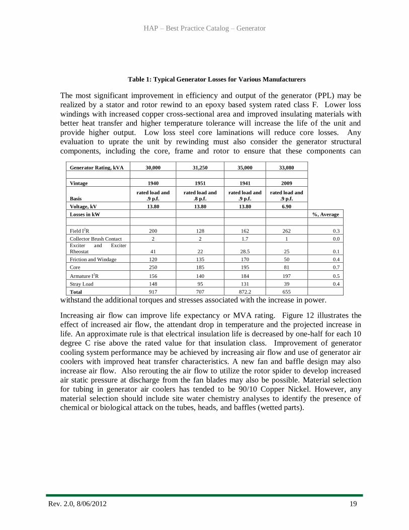
Table 1: Typical Generator Losses for Various Manufacturers
The most significant improvement in efficiency and output of the generator (PPL) may be
realized by a stator and rotor rewind to an epoxy based system rated class F. Lower loss
windings with increased copper cross-sectional area and improved insulating materials with
better heat transfer and higher temperature tolerance will increase the life of the unit and
provide higher output. Low loss steel core laminations will reduce core losses. Any
evaluation to uprate the unit by rewinding must also consider the generator structural
components, including the core, frame and rotor to ensure that these components can
withstand the additional torques and stresses associated with the increase in power.
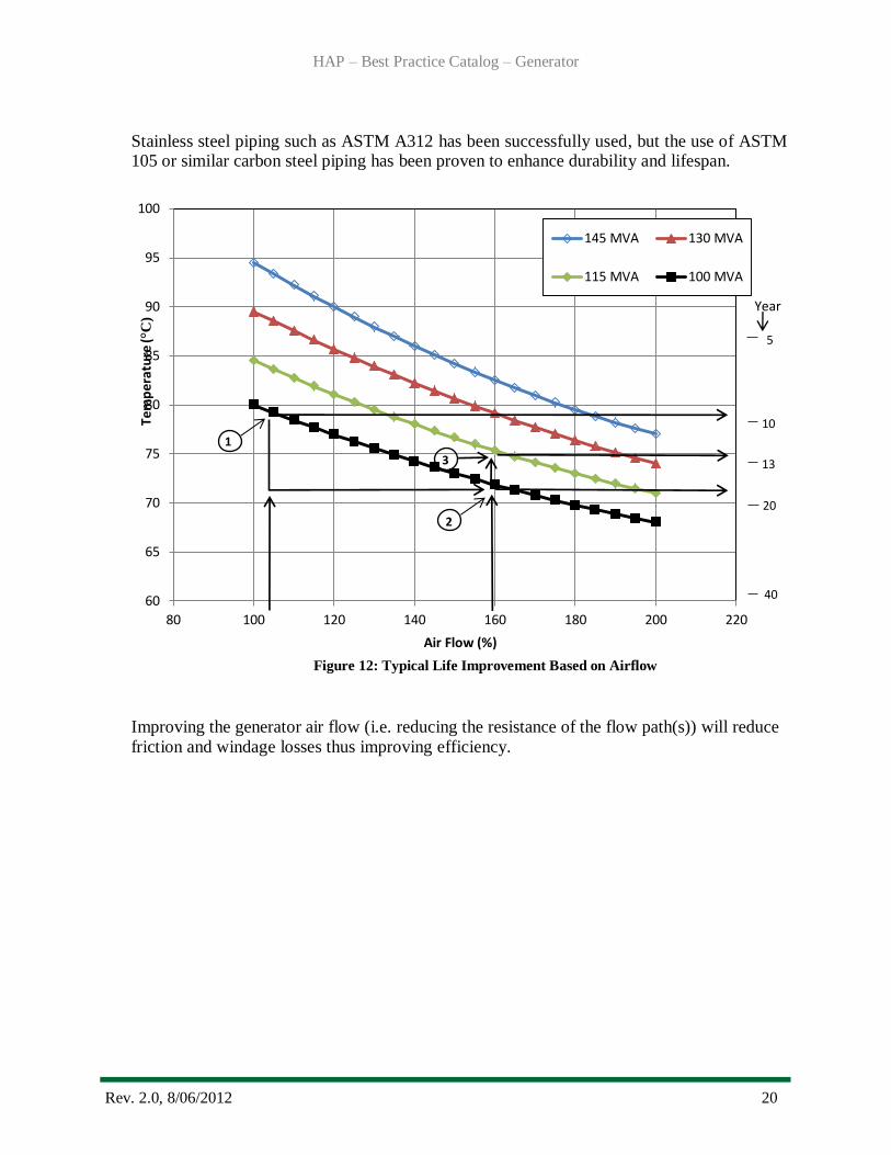
Increasing air flow can improve life expectancy or MVA rating. Figure 12 illustrates the
effect of increased air flow, the attendant drop in temperature and the projected increase in
life. An approximate rule is that electrical insulation life is decreased by one-half for each 10
degree C rise above the rated value for that insulation class. Improvement of generator
cooling system performance may be achieved by increasing air flow and use of generator air
coolers with improved heat transfer characteristics. A new fan and baffle design may also
increase air flow. Also rerouting the air flow to utilize the rotor spider to develop increased
air static pressure at discharge from the fan blades may also be possible. Material selection
for tubing in generator air coolers has tended to be 90/10 Copper Nickel. However, any
material selection should include site water chemistry analyses to identify the presence of chemical or biological attack on the tubes, heads, and baffles (wetted parts).
Generator Rating, kVA 30,000 31,250 35,000 33,080
Vintage 1940 1951 1941 2009
Basis
rated load and
.9 p.f.
rated load and
.8 p.f.
rated load and
.9 p.f.
rated load and
.9 p.f.
Voltage, kV 13.80 13.80 13.80 6.90
Losses in kW
%, Average
Field I
2R 200 128 162 262 0.3
Collector Brush Contact 2 2 1.7 1 0.0
Exciter and Exciter
Rheostat 41 22 28.5 25 0.1
Friction and Windage 120 135 170 50 0.4
Core 250 185 195 81 0.7
Armature I2R 156 140 184 197 0.5
Stray Load 148 95 131 39 0.4
Total 917 707 872.2 655
HAP – Best Practice Catalog – Generator
Rev. 2.0, 8/06/2012 20
60
65
70
75
80
85
90
95
100
80 100 120 140 160 180 200 220
Tem
pe
ratu
re (°
C)
Air Flow (%)
145 MVA 130 MVA
115 MVA 100 MVA
13
20
40
5
10
1
2
3
Year
Stainless steel piping such as ASTM A312 has been successfully used, but the use of ASTM 105 or similar carbon steel piping has been proven to enhance durability and lifespan.
Figure 12: Typical Life Improvement Based on Airflow
Improving the generator air flow (i.e. reducing the resistance of the flow path(s)) will reduce
friction and windage losses thus improving efficiency.
HAP – Best Practice Catalog – Generator
Rev. 2.0, 8/06/2012 21
3.0 Operation & Maintenance Practices
3.1 Condition Assessment
The generator system condition is largely a function of its age, the way it has been
maintained, the way it has been operated, and the adequacy of its design. Generator losses
can often be attributed to the machine design and the materials used in its construction. The
impact of the ventilation system on losses is most often seen in the change in resistance of
the copper at different temperatures. While this change is typically small and the resistances
are very small, it does have a calculated effect on losses. A thorough condition assessment of
all the generator components will be difficult without an outage and some level of
disassembly. Various test and maintenance inspections and on-line monitoring can provide a
reasonable condition assessment of the generator. While overall age is a factor, units that are
cycled frequently are subject to increased thermal stresses that contribute significantly to a
deteriorated condition that ultimately affects total generation. Likewise, units operated
outside their capability curves by exceeding recommended temperatures, will have increased
losses, reduced time to failure, and consequently reduced total generation.
The design and capacity of the system should match the operational requirements, i.e. turbine input power. The generator rating should be adequate for the available turbine power.
The RCW Motor Operated Isolation Valve opens when a unit starts and closes when a unit
stops. The motor and valve condition can largely established by operation history and age.
The RCW pump and motor is normally a centrifugal pump with an induction motor.
Developed pressure across the pump with rated flow (from a RCW flow meter) is usually
sufficient to determine if the pump is operating acceptably. The RCW strainer condition can
be evaluated based on pressure differential across the strainer and its performance after a back flush to operate at rated pressure drop or lower.
RCW pipe is difficult to evaluate for wall thickness due to fouling on the inside of the pipe
that may be ½ to ¾ of an inch on 6-8” pipe. Pinhole leaks may ultimately develop along the length of the piping system so replacement is typically justified.
The manual valves can be operated to determine if it is properly operated. Condition of disc,
seats and other internal components would require removal from the pipe connections. Age is the major factor in the manual valve’s life.
RCW cooling systems instrumentation should be routinely checked for accuracy, especially
air cooler thermocouples/resistance temperature detectors (rtd’s), pressure gages and flow
meters. Some temperatures can be checked with hand held pyrometers or thermal imaging
equipment, depending on the accessibility. Instrumentation accuracy is subject to
deterioration due to corrosion, loose connections, electrical deterioration, obstructed or
blocked flow passages or mechanical damage.
Generator air cooler condition can be evaluated by checking cold air temperature variations
in the vertical and horizontal directions across the face of the cooler and the overall
temperature drop/rise of the coolants. Significant variations across the horizontal and vertical
dimensions (> 8° F) may be due to air gap problems or localized hot spots in the armature.
HAP – Best Practice Catalog – Generator
Rev. 2.0, 8/06/2012 22
Fins should be inspected for contact with the tubes. It is possible to check air pressure drop
across the coolers depending on the accessibility. Degradation/loss of generator air cooler
head baffles will result in poor cooling efficiency and cold air temperatures that are 20°C above the RCW temperature.
Condition of the proportioning valves can be readily determined as to whether the valves are
adjusting water flow for the variations in air temperature.
For plants that derive cooling water from the tailwater with a pumped system and a throttling valve, parasitic pump losses may be reduced by converting to a variable speed pump.
The generator fan blades are fabricated assemblies that are typically attached to the top and
bottom of the rotor rim. Inspections can identify fatigue cracks, defective welds, loose hardware or mechanical damage that may impact cooling.
Although the system stator’s electrical insulation integrity has no correlation with losses, it is
important to note that insulation failure will result in lost generation. Insulation integrity is
reduced with age increasing. Increased age exposes insulation to the cumulative effects of
thermal stress and cycling, vibration and mechanical damage, and deleterious contaminates.
A variety of electrical tests may be performed to aid in assessing insulation condition, and the
majority of accepted industrial techniques for generator condition assessment are associated
with testing and monitoring of the insulation system. A number of these tests and techniques
are identified in Information Sources [10 and 17]. Partial discharge monitoring systems have
been developed that can provide an on-line trending tool for monitoring insulation condition
with the advantage of having the unit under operating conditions.
The generator rotor can be inspected on a periodic basis for loose hardware, pole
overheating, pole electrical connection integrity, air gap, rotor roundness, loose fans, loose
shrink keys, brake ring heating or deformation. Structural components can be non
destructively examined (NDE) for cracks or failures. During operation, vibration should be
trended, and apparent causes for excessive levels of vibration include eccentricity between
the rotor and stator, bearing issues, air gap anomalies, or alignment. While no standards
identify acceptable levels of vibration, IEEE 492 addresses “Vibration Detection and
Correction”. Trip and alarm setpoints for a specific unit should be established by the
Original Equipment Manufacturer (OEM) or by operating experience.
The condition assessment of the oil lubricated thrust and guide bearing includes vibration
measurements and temperature of the bearing in operation. Abnormal indications could be a
sign of failure of the babbitted surface (wipe), un-bonding of the babbitt from the bearing shoe, or contamination of the oil which can be established by oil sample analyses.
3.2 Operations
It is recognized that the rating of the generator may not be matched to the load capability of
the turbine. However, loading of the generator should be maintained within the manufacturer’s capability curve.
HAP – Best Practice Catalog – Generator
Rev. 2.0, 8/06/2012 23
Stator and rotor winding temperature limits are based on NEMA insulation class, and should be
continually monitored. Any trends indicating increased operating temperatures under the same load and ambient conditions should be investigated for issues with the cooling system.
Output of the unit is limited in the “overexcited” region by the operating temperature of the field (excitation system) and may be limited by core end heating in the “under excited” region. Generally,
measurements of the field and core temperature are collected using embedded resistance temperature
detectors or indirect methods. The limits must be maintained for rated output of the unit.
It is not unusual for a hydro generator to be operated with failed coils cut out of the winding path.
This is generally done to minimize repair cost and to expedite the return to service following a coil failure. The manufacturer should be consulted in these cases to determine deratings and remediation
measures required. Any losses associated with this setup can be restored by replacing the failed coils.
Marginal operational control of a typical generator cooling system is possible due to the design. One
exception is proportioning valves to control RCW flow to the generator air coolers to maintain a
constant hot or cold air temperature. The benefit of the proportioning valve is in a situation where the generator is operating in load following mode with significant changes in MVA output. The valve
controller would be set to the desired air temperature.
The generator rotor should have a significant margin for fatigue failure under design loadings
including design basis transients. Operation at higher MW output may accelerate fatigue damage of
components and should be evaluated by analyses. Also the operation of the generator at higher MVA and PF conditions may result in high field temperatures that tend to loosen the shrink of the rim to the
rotor arm keys. Operational limits should be imposed for the generator as a machine with all
structures, components and assemblies evaluated.
3.3 Maintenance
A well designed and supported Maintenance Program is essential to the reliability, operation and
maintenance planning for the generator. Maintenance procedures are needed to ensure that consistent
and effective maintenance is performed. These procedures should be based on manufacturers’ recommendations and operating experience.
Deterioration of the cooling system effectiveness may be caused by misoperation of heat exchangers, rotor fans, automatic cooler controls, fouling of stator vents, or ambient conditions. Any decrease in
cooling effectiveness is subject to increased I2R (resistance R by the current I squared) losses. The
generator RCW pipe and generator air cooler tubes foul in any system. The cleaning of the RCW pipe is probably of minimum value unless the fouling reduces RCW flow below design value. If design
flow rates are not achievable with adequate pump or head pressure, fouled or obstructed piping may
be the cause. Water jet or hydrolaze cleaning of RCW piping may improve flow rates. The generator air cooler tubes are more vital and require periodic cleaning to maintain the acceptable performance
when indicated by excessive cold air temperatures. Another potential problem in the older generator
air coolers was the baffles that were designed to create an effective heat transfer path for the RCW.
After years of service, these baffles are totally degraded or lost, resulting in a heat exchanger with poor performance. Also, the fins may become separated from the tubes which effectively eliminate
the fins surface from heat transfer. Degraded baffles should be repaired and new gaskets installed on
the heads. Degradation of generator air cooler tubes may result in leaks and water being transported to the stator and field coils. Air cooler cleaning is typically accomplished by removing the coolers from
the generator. The coolers should be cleaned annually, or even more frequently, if severe fouling
occurs. The heads are removed and the tubes can be cleaned with a tool. In severe cases of unusual
HAP – Best Practice Catalog – Generator
Rev. 2.0, 8/06/2012 24
biological fouling, it may be necessary to increase the cleaning frequency. Frequencies may require
seasonal adjustments.
The rotor assembly requires minimum maintenance except to inspect the bolted connections/keys and
correct any loose assemblies, shaft/rotor mating fretting, field leads on the rotor arm, rim studs, fans blades, and poles. Shrunk on collars should be examined for fretting of surfaces if access is possible.
The tightness of the shrink keys should also be checked in machines with 30-40 years of service. A
re-shrink of the rim may be desirable to reestablish the compressive load on the rotor arms and ensure acceptable contact between the rim/pole assembly and the arm key. NDE examinations of structural
welds and attachments should be conducted on a periodic basis. The maintenance procedure should
include the periodic measurement of rotor air gap data. The reduced air gap may be due to frame/core
movement, rotor rim issues or pole mounting issues. The interpole electrical connections (including amortisseur windings) should also be checked for indication of overheating or mechanical failure or
damage.
The stator bolted connections in the phase and neutral lead assembly should be checked and tightened
either during outage or checked indirectly by temperature measurement during operation. Minor I2R
losses may be seen here if connections have deteriorated or been made improperly. Generator inspections and testing should be performed periodically by individuals’ knowledgeable in generator
design, operations and maintenance. Generator reliability is highly dependent on the ability to detect
and address incipient issues affecting the integrity of the stator winding.
As seen in Table 1, the collector ring and brush assemblies often account for small losses (excitation
system). To minimize these losses, operators should follow the manufacturers’ recommendations relative to collector rings and brush rigging. The brush dust generated by the collector ring and
commutator brushes (if present) makes this a high maintenance area. Lack of attention in this area can
result in a flashover due to the low resistance tracking paths caused by the brush dust.
Perform NDE on stator structural frame welds during major outages or as indicated by operating
experience.
The stator core should be cleaned if the winding is removed for rewind. This will facilitate visual
inspection, clean cooling vents, and remove contaminates that may affect heat transfer. IEEE 1665 [23] suggest several methods of either blast or solvent cleaning for the core as well as inspection
techniques for core inspections.
Generator Neutral Grounding Systems traditionally are constructed using distribution transformers,
resistors, and/or inductors. Contamination may cause tracking during fault conditions resulting in
higher fault current for a line to ground fault, which could in turn result in more damage to the generator iron. Other components associated with the neutral grounding system include breakers and
disconnect, which should be visually inspected. Oil filled breakers or grounding
inductors/transformers should be checked for leakage. Cleaning and testing is recommended on a scheduled basis as determined by the manufacturer’s recommendations and operating experience.
HAP – Best Practice Catalog – Generator
Rev. 2.0, 8/06/2012 25
4.0 Metrics, Monitoring and Analysis
4.1 Measures of Performance, Condition, and Reliability
Reductions in stator operating temperature will reduce the value of R and consequently the
I2R losses. However, the R factor in this equation is minor in comparison to the I
2 factor.
Personnel should also take caution that they must follow the manufacturer’s operating
temperature guidelines to prevent damaging differential expansions between generator
structural and winding components.
Determination of other losses (e.g., windage and friction, core, stray load, and excitation
system) requires various measurements made during different modes of performance testing
as described in IEEE 115 [10]. These losses are originally calculated and provided by the
manufacturer, but the cost of retesting to determine any deterioration or improvement should
be compared to the potential expected benefit.
The largest losses in the generator are the I2R losses in the stator and rotor. An
approximation of these losses can be calculated and compared to design values in an effort to
determine the gap between the IPL and CPL. Accurate resistance measurements of
components subject to I2R losses at a reference temperature are required. Methods of
temperature determination include thermometer methods, embedded detector methods,
coolant temperature measurements, and indirect measurement with scanning devices.
Voltage and current measurements are also required to determine resistance at operating
temperature. Loss in watts is calculated by multiplying the resistance R by the current I
squared, or I2R.
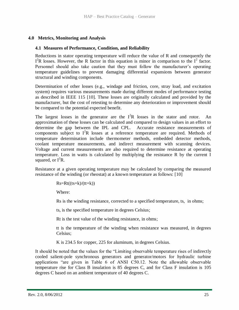
Resistance at a given operating temperature may be calculated by comparing the measured resistance of the winding (or rheostat) at a known temperature as follows: [10]
Rs=Rt((ts+k)/(tt+k))
Where:
Rs is the winding resistance, corrected to a specified temperature, ts, in ohms;
ts, is the specified temperature in degrees Celsius;
Rt is the test value of the winding resistance, in ohms;
tt is the temperature of the winding when resistance was measured, in degrees
Celsius;
K is 234.5 for copper, 225 for aluminum, in degrees Celsius.
It should be noted that the values for the “Limiting observable temperature rises of indirectly
cooled salient-pole synchronous generators and generator/motors for hydraulic turbine
applications “are given in Table 6 of ANSI C50.12. Note the allowable observable
temperature rise for Class B insulation is 85 degrees C, and for Class F insulation is 105
degrees C based on an ambient temperature of 40 degrees C.
HAP – Best Practice Catalog – Generator
Rev. 2.0, 8/06/2012 26
Generator shaft vibration is a measure of performance and reliability. Vibration
measurements may include shaft displacement (x and y) at selected elevations along the axis
of the shaft. A vibration monitoring system should be installed with unit alarm and trip values set based on operating experience and manufacturers’ recommendations.
4.2 Data Analysis
Generator IEEE 115 test data is typically evaluated against the IPL test data and
manufacturers calculated data. It is typically very difficult to obtain test data at the rated
MVA, KV and PF conditions. Therefore, the test losses at lower ratings are extrapolated to
the machine rated values.
For units with air/water heat exchangers, some owners have used the calorimetric method
described in IEEE 115 to obtain existing machine segregated losses. This method is easier to
set up for an existing station than other recognized methods of measuring losses.
Trend analysis of bearing temperatures, generator vibrations and oil sample data will be
necessary to reasonably establish the bearing CPL. These analyses should compare results to
previous or test data from commissioning of the unit (IPL). This data can be compared to OEM data if available for bearing losses, operating temperatures and potential failures.
4.3 Integrated Improvements
The use of periodic IEEE 115 test may be used to update the unit operating characteristics
and limits. This also provides data to evaluate the stator/rotor condition. Optimally the heat
run data obtained would be integrated into an automatic system (e.g., Automatic Generation
Control), but if not, hard copies of the curves and limits should be made available to all involved personnel.
HAP – Best Practice Catalog – Generator
Rev. 2.0, 8/06/2012 27
5.0 Information Sources
Baseline Knowledge:
1. Liwschitz-Garik, M., Whipple C., Electric Machinery Vol.1 Fundamentals and D.C. Machines - Third Printing July 1947
2. Chapman, Alan J., Heat Transfer - Third Edition, Macmillan Publishing 1974
3. Buffalo Forge Company, Fan Engineering - Eighth Edition 1983
4. Walker, John, Large Synchronous Machines Design Manufacture and Operation -
Clarendon Press Oxford 1981
5. TVA, Design of Projects Technical Report No. 24 Electrical Design of Hydro Plants
6. Electric Power Research Institute, Handbook to Assess the Insulation Condition of Large Rotating Machines, EPRI EL-5036, Volume 16, June 1989.
State of the Art:
7. Sumereder, C., Muhr, M., Korbler, B., Life Time Management of Power Transformers - Graz University of Technology – Austria TUG Sumereder A1 Session 1, Paper No. 35-1
8. Fenwick, G.T., Generator Air Cooler Design and Selection for Optimum Performance,
Upgrading and Refurbishing Hydro Plants - Unifin Corporation October 29,1991
9. Lehoczky, K. N., Generator Life Expectancy Extension and Increased MVA Output
through Three-Dimensional Cooling Design - HydroVision 94 Conference, Phoenix,
Arizona.
Standards:
10. IEEE 115, Guide, Test Procedures for Synchronous Machines
11. IEC 32, Part 2 International Electro Technical Commission Methods of Determining
Losses and Efficiency Of Rotating Electrical Machinery from Test (Excluding Machines for Traction Vehicles) Measurement of Losses by the Calorimetric Method
12. ANSI C50.10 American National Standard: Rotating Electrical Machinery -
Synchronous Machines
13. ANSI, C50.12 – IEEE Standard for Salient-Pole 50Hz and 60 Hz Synchronous
Generators and Generator/Motors for Hydraulic Turbine Applications Rated 5 MVA and
Above
14. IEEE, 1 - Recommended Practice — General Principles for Temperature Limits in the Rating of Electrical Equipment and for the Evaluation of Electrical Insulation
15. IEEE, STD 492 Guide for Operation and Maintenance of Hydro-Generators
16. ANSI/IEEE Std 1010-1987 An American National Standard IEEE Guide for Control of
Hydroelectric Power Plants
HAP – Best Practice Catalog – Generator
Rev. 2.0, 8/06/2012 28
17. Recommended Practice for Testing Insulation Resistance of Rotating Machinery, IEEE Std 43, 2000.
18. American National Standard for Rotating Electrical Machinery - Synchronous Machines,
ANSI C50.10.
19. ISO 7919 Mechanical Vibrations on Non Reciprocating Machines Measurements on Rotating Shafts and Evaluation Part 5 Guidelines for Hydraulic Machine Sets
20. ORNL et al, HAP Condition Assessment Manual, October, 2011
21. IEEE STD C62.92.2, Guide for the Application of Neutral Grounding in Electric Utility
Systems : Part II – Grounding of Synchronous Generator Systems
22. IEEE STD 1147, Guide for the Rehabilitation of Hydro Plants
23. IEEE STD 1665, Guide for the Rewind of Synchronous Generators, 50 Hz and 60 Hz, Rated 1 MVA and Above.
It should be noted by the user that this document is intended only as a guide. Statements are of a
general nature and therefore do not take into account special situations that can differ
significantly from those discussed in this document.
HAP – Best Practice Catalog – Generator
Rev. 2.0, 8/06/2012 29
For overall questions
please contact:
Brennan T. Smith, Ph.D., P.E. Water Power Program Manager
Oak Ridge National Laboratory
865-241-5160 [email protected]
or
Qin Fen (Katherine) Zhang, Ph. D., P.E.
Hydropower Engineer
Oak Ridge National Laboratory 865-576-2921