Embed Size (px)
Citation preview

1
HUC64-00
digimess®
GEBRAUCHSANWEISUNG OPERATING INSTRUCTIONS
Bestell-Nr. Order No.
HF SIGNALGENERATOR
RF SIGNAL GENERATOR
SG200

2
Subject to alterations, errors excepted
Reprints, also in extracts, are only allowed with written permission of the manufacturer.
All rights reserved.
Copyright 2013
Änderungen und Irrtümer vorbehalten.
Nachdruck, auch auszugsweise, nur mit schriftlicher Genehmigung des Herstellers.
Alle Rechte vorbehalten.

3
SG200 RF Signal Generator
Operating Instructions
1.0 Mains Connection
The design of the unit meets the requirements of safety class I according to EN 61010-1, i.e. all metal parts
accessible from outside and exposed to contact are connected with the protective conductor of the supply
network.
Power is supplied via a mains cable with earthing contact
1.1 Installing the signal generator
The signal generator should not be operated close to equipment that develops heat. To protect the unit from
thermal overload the air vents must not be covered and a free space of about 10 cm should be ensured.
1.2 Switching on
The signal generator is switched on using the power switch at the front. The power switch separates the unit
completely from the primary side of the transformer.
1.3 EMC
The signal generator is interference-free according to EN 50081-1 and EN 50081-2. In order to fulfil the lim-
it values in line with present standards, it is absolutely necessary that only cables which are in perfect condi-
tion be connected to the unit.
1.4 Inspection and Maintenance
If service is needed, due attention should be paid to the regulations according to VDE 0701. The signal gen-
erator should only be repaired by trained personnel.

4
1.5 Warranty
The perfect working order of the signal generator is guaranteed for 12 months as from delivery.
There is no warranty for faults arising from improper operation or from changes made to the signal generator
or from inappropriate application.
If a fault occurs please contact or send your signal generator to:
The signal generator should be sent in appropriate packing - if possible in the original packing. Please en-
close a detailed fault report (functions working incorrectly, deviating specifications and so on) including unit
type and serial number.
Would you also kindly verify warranty cases by enclosing your supply delivery note. Any repairs carried out
without reference to a valid warranty will initially be at the owner’s expense.
Should the warranty have expired, we will, of course, be glad to repair your signal generator as per our Gen-
eral Terms Of Assembly And Service.
1.6 Description
The digimess®
SG200 is a DDS synthesised RF signal generator. The unit covers the frequency 9kHz to
450MHz with a resolution of 1Hz and auto switches between the Internal or an External frequency reference.
The SG200 has a 4.3 inch TFT colour display, numeric keypad or rotary control data input and amplitude
can be entered in either dBm, mV, µV or dBµV. The generator includes AM, FM and Phase modulation
along with FSK, PSK and Sweep facilities. Up to 8 instrument set-ups can be stored in the non-volatile
memory and the unit features both USB and RS232 interfaces with a USB lead and software supplied.
2 Technical Data
2.1 General Data
Nominal temperature: + 23 °C 1 °C
Operating temperature: + 0°C to + 40 °C
Relative humidity: >75%
Atmospheric pressure: 70 to 106 kPa
Operating position: horizontal or inclined by 15 °
Operating voltage: sinusoidal alternating voltage (distortion factor < 5 %)
200-250Vac 30VA
Frequency: 50/60 Hz
Safety class: 1, according to EN 61010 Part 1
Radio interference suppression: EN 55011 Class B
Agents details :

5
2.2 Specifications
Specification
DISPLAY
Size
Type
FREQUENCY
Range
Resolution
Accuracy
Settling
FREQUENCY REFERENCE
Internal or external
Internal Reference
Stability
External frequency input
OUTPUT
Level
Resolution
Entry format
Accuracy
Attenuation precision
SWR
RF output impedance
Harmonics
Non-harmonics
Sub-harmonics
MODULATION SOURCE
Type
Internal
External
FM MODULATION
Peak deviation
Resolution
Accuracy
Distortion
Source
FSK
Source
Ranges
4.3 inch
TFT colour LCD
9kHz - 450MHz
(< 100kHz amplitude un-calibrated)
1Hz
See Frequency Reference
< 100ms to within 100Hz
Automatic switch over
TCXO 10.000MHz
±2.5ppm +15°C - +30°C
10MHz 0.3Vrms - 1Vrms 50Ω
-127dBm - +13dBm
(0.1µV - 1000mV into 50Ω)
0.1dB, 0.1µV, 0.1dBµV
dBm, mV, µV, dBµV
±1dB at level +4dBm > 400kHz
±2dB at < -105dBm
< 1.5 at carrier freq > 300kHz and
level < -6dBm
50Ω
< -15dBc at level ≤ +4dBm
< -40dBc at level ≤ +4dBm
< -40dBc at level ≤ +4dBm
Internal or external
400Hz or 1kHz, output 1Vpk
0 - 1Vpk 600Ω
0 - 100kHz
100Hz
±5% ±50Hz 1kHz Int, > 5kHz
<3% 1kHz Int, >10kHz 300Hz-3kHz
Internal 400Hz or 1kHz
External TTL level
100kHz - 1.5MHz FSK < 25kHz
1.5MHz - 20MHz FSK < 25kHz
20MHz - 75MHz FSK < 50kHz
75MHz - 140MHz FSK < 2kHz
140MHz - 260MHz FSK < 2kHz
260MHz - 360MHz FSK < 2kHz
360MHz - 450MHz FSK < 2kHz
FREQUENCY SWEEP
Frequency (start)
Ranges
Sweep width
Step frequency
Step time
Stop frequency
AM MODULATION
Carrier frequency
Range
Resolution
Accuracy
Source
Distortion
PHASE MODULATION
Source
Phase deviation
Resolution
PSK
Source
Ranges
Phase 1 and Phase 2
Resolution
NON-VOLATILE STORAGE
Number of instrument set-ups
INTERFACE
Type
GENERAL
Input voltage
Weight
Size W x H x D
Temperature
Humidity
ORDERING INFORMATION
HUC64-00 SG200
Accessories supplied
100kHz - 450MHz resolution 1Hz
100kHz - 75MHz, 75MHz -
140MHz, 140MHz - 260MHz,
260MHz - 360MHz,
360MHz - 450MHz
1kHz - 99.99MHz
1Hz - 99.99MHz
10µs - 10s, 10µs steps
= start frequency + sweep width
(within above ranges)
≥ 1.5MHz
0 - 120% (> 70% un-calibrated)
0 - 70% (≤ +4dBm, ≤ 75MHz)
0 - 50% (≤ +4dBm, > 75MHz)
1% (modulation ≥ 10%)
0.1% (modulation < 10%)
< ±7% settled value ±1.5%
(Internal, 1kHz ≤ 30%)
Int or Ext 20Hz - 10kHz
< 5% (1kHz, 30%, 300Hz - 3kHz)
Internal 400Hz or 1kHz
0.1 rads - 6.0 rads
0.1 rads
External TTL level
See FSK
0.1° - 360°
0.1°
8
Standard USB and RS232
200-250Vac 50/60Hz ≤ 30VA
3kg
250 x 120 x 400 mm
Operating 0°C - 40°C
Storage -10°C - +60°C
Up to 75%
RF signal generator
Operators manual, BNC test lead,
software, USB and mains lead
6
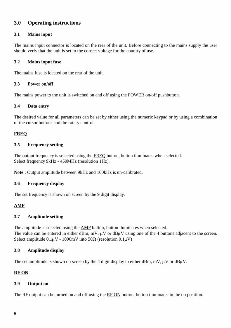
3.0 Operating instructions
3.1 Mains input
The mains input connector is located on the rear of the unit. Before connecting to the mains supply the user
should verfy that the unit is set to the correct voltage for the country of use.
3.2 Mains input fuse
The mains fuse is located on the rear of the unit.
3.3 Power on/off
The mains power to the unit is switched on and off using the POWER on/off pushbutton.
3.4 Data entry
The desired value for all parameters can be set by either using the numeric keypad or by using a combination
of the cursor buttons and the rotary control.
FREQ
3.5 Frequency setting
The output frequency is selected using the FREQ button, button iluminates when selected.
Select frequency 9kHz - 450MHz (resolution 1Hz).
Note : Output amplitude between 9kHz and 100kHz is un-calibrated.
3.6 Frequency display
The set frequency is shown on screen by the 9 digit display.
AMP
3.7 Amplitude setting
The amplitude is selected using the AMP button, button iluminates when selected.
The value can be entered in either dBm, mV, V or dBV using one of the 4 buttons adjacent to the screen.
Select amplitude 0.1V - 1000mV into 50 (resolution 0.1V)
3.8 Amplitude display
The set amplitude is shown on screen by the 4 digit display in either dBm, mV, V or dBV.
RF ON
3.9 Output on
The RF output can be turned on and off using the RF ON button, button iluminates in the on position.

7
MOD
3.10 Modulation
The modulation menu is accessed by the MOD button, button iluminates when selected.
3.11 Modulation type
AM, FM, FSK, PSK, PM and sweep modes can be selected using one of the 4 buttons adjacent to the screen.
3.11.1 AM
Select modulation depth from 0 - 120% (resolution 0.1% <10%, 1% >10%)
Select source from either INT 1kHz, INT 400Hz or External
Note : modulation depth 70% - 120% is un-calibrated
3.11.2 FM
Select frequency deviation 0 - 100kHz (resolution 100Hz)
Select source from either INT 1kHz or INT 400Hz
3.11.3 PAM
Not available on SG200
3.11.4 FSK
Select frequency 9kHz - 450MHz (resolution 1Hz)
Select Hop frequency 0 - 74MHz
Modulation source is external only
Refer to paragraph 2.2 Specifications for frequency ranges
3.11.5 PSK
Select Phase 1 0.1 - 360 (resolution 0.1)
Select Phase 2 0.1 - 360 (resolution 0.1)
Modulation source is external only
Refer to paragraph 2.2 Specifications for frequency ranges
3.11.6 PM
Select Phase deviation 0.1 rads - 6 .0 rads (resolution 0.1 rads)
Select source from either INT 1kHz or INT 400Hz

8
3.11 Modulation type (continued)
3.11.7 SWEEP
Select frequency (Start frequency) 100kHz - 450MHz (1Hz resolution)
Select sweep width (Stop frequency = Start frequency + Sweep width) 1kHz - 99.99MHz
Select step frequency (Frequency increment) 1Hz - 99.99MHz
Select step time (Time for each frequency increment) 10s - 10s (10s increments)
Refer to paragraph 2.2 Specifications for frequency ranges showing maximum sweep widths
3.11.8 STEREO
Not available on SG200
MOD ON
3.12 Modulation on
The modulation can be turned on and off using the MOD ON button, button iluminates in the on position
AF
3.13 Audio generator
Not available on SG200
COUN
3.14 Counter
Not available on SG200
SYS
3.15 System
The System menu is accessed by the SYS button, button iluminates when selected.
3.15.1 STORE
Non-volatile storage of upto 8 instrument settings using address locations between 00 and 07.
3.15.2 RECALL
Recalls upto 8 instrument settings using address locations between 00 and 07.
3.15.3 GPIB
Not available on SG200

9
3.15 System (continued)
3.15.4 RESET
System reset
INPUT/OUTPUT CONNECTORS
3.16 RF OUT
The RF signal is output from the RF OUT connector located on the front panel.
3.17 MOD IN/OUT
The MOD IN/OUT connector allows the connection of both input and output modulation signals and is
located on the front panel.
3.18 FSK/BPSK (TTL)
The FSK/BPSK (TTL) connector allows the connection of the input signal and is located on the rear panel.
3.19 REF IN
The REF IN connector allows the connection of an external frequency reference of 10MHz with an
amplitude 0.3Vrms - 1Vrms (50 load) and is located on the front panel.
3.20 USB
The USB connectors are located on the front and rear panel and allow the unit to be connected to a pc.
Software is supplied with the equipment and the USB protocol is given in paragraph 5.
3.15 RS232
The RS232 connector is located on the rear panel and allows the unit to be connected to a pc. Software is
supplied with the equipment.

10
4.0 Principle of operation
INT. frequency
Audio IN/OUT
+12 V
-12V control level
AM
Power
filter
Phase
detector divide
VCO
DDS
Band
switch
attenuation
ALC
demodulati
on
检波
microcomputer display
keys filter
filter and
amplify amplification
+5V -5V +3.3V
Modulation
control
FSK RF OUT
10MHz
EXT. frequency
FSK
Reference
control
Attenuation
Main board

11
5.0 USB Protocol
1) Connection:
1) Connect the SG200 to the PC using a USB cable.
2) Power on the SG200. When connecting to the PC for the first time the PC will prompt found new
hardware and need to install the driver. Choose the folder “USB Driver” to install the driver.
3) After the installation of the driver is completed, run USBTest.exe. The following commands can then
be used to control the SG200.
2) SG200 Command Set for USB communication:
1) Carrier wave frequency set:
Command: F:XX.XXXXXXMHz(kHz, Hz)
Description: set carrier wave frequency (no space between characters)
Example: F:20MHz (set carrier wave frequency at 20MHz)
2) Carrier wave amplitude set:
Command: Amp:XX.XXdBm(dBuV, mV, uV)
Description: set carrier wave amplitude (no space between characters)
Example: Amp:5dBm (set carrier wave amplitude at 5dBm)
Amp:5dBuV (set carrier wave amplitude at 5dBuV)
Amp:5mV (set carrier wave amplitude at 5mV)
Amp:5uV (set carrier wave amplitude at 5uV)
3) AM set:
Command: AM
Description: set AM modulation
Command: F:XX.XXXXXXMHz(kHz, Hz)
Description: set carrier frequency (no space between characters)
Example: F:12MHz (set carrier frequency at 12MHz)
Command: Dep:XX
Description: set modulation depth (no space between characters)
Example: Dep:23 (set modulation depth at 23%)
4) FM set:
Command: FM
Description: set FM modulation
Command: F:XX.XXXXXXMHz(kHz, Hz)
Description: set carrier frequency (no space between characters)
Example: F:2MHz (set carrier frequency at 2MHz)
Command: Dev:XX.XkHz(Hz)
Description: set deviation (no space between characters)
Example: Dev:23kHz (set deviation at 23kHz)
5) FSK set:
Command: FSK
Description: set FSK modulation
Command: Freq1:XX.XXXXXXMHz(kHz, Hz)
Description: set frequency 1 (no space between characters)
Example: Freq1:500kHz (set frequency 1 at 500kHz)
Command: Freq2:XX.XXXXXXMHz(kHz, Hz)
Description: set frequency 2 (no space between characters)

12
Example: Freq2:1MHz (set frequency 2 at 1MHz)
6) Sweep set:
Command: SWP
Description: set sweep mode
Command: StartF:XX.XXXXXXMHz(kHz, Hz)
Description: set start frequency (no space between characters)
Example: StartF:500kHz (set start frequency at 500kHz)
Command: StopF:XX.XXXXXXMHz(kHz, Hz)
Description: set stop frequency (no space between characters)
Example: StopF:10MHz (set stop frequency at 10MHz)
Command: StepF:XX.XXXXXXMHz(kHz, Hz)
Description: set step frequency (no space between characters)
Example: StepF:1MHz (set step frequency at 1MHz)
Command: HoldTime:XXXmS
Description: set hold time of each step (no space between characters)
Example: HoldTime:200mS (set hold time at 200mS)
7) Store/Recall (No. 00~07):
Command: Recall:XX
Description: recall no. XX setting (no space between characters)
Example: Recall:02 (recall no. 02 setting)
Command: Store:XX
Description: Store no. XX setting (no space between characters)
Example: Store:00 (store no. 00 setting)
8) Internal modulation wave selection:
Command: 1kHz
Description: select 1kHz internal modulation wave
Command: 400Hz
Description: select 400Hz internal modulation wave
9) Internal/External modulation selection:
Command: Internal
Description: select internal modulation wave
Command: External
Description: select external modulation wave
10) Modulation on/off selection:
Command: ModuOn
Description: turn on modulation
Command: ModuOff
Description: turn off modulation
11) RF on/off selection:
Command: RFOn
Description: turn on RF output
Command: RFOff
Description: turn off RF output
Note: All commands are case sensitive, Click “SEND” button to send command. ENTER” key on keyboard
has no effect.

13
digimess®
Konformitatserklarung Declaration of Conformity / Declaration de Conformite CE
Der Hersteller/importeur The manufacturer/importer Le producteur/importateur Anschrift/Address/Adresse erklart hiermit eigenverantwortlich, dass das Produkt : hereby declares that the product : declare, que le produit : Bezeichnung/Name/Description Type/Model/Type Bestell-Nr/Order No/No de ref folgenden Normen entspricht : is in accordance with the following specifications : correspond aux normes suivantes : Das Produkt erfullt somit die Forderungen folgender EG-Richtlinien : Therefore the product fulfills the demands of the following EC-Directives : Le produit satisfait ainsi aux conditions des directives suivantes de la CE : 73/23/EWG 89/336/EWG Derby, 7.10.2012
Digimess Instruments Ltd Stenson House Stenson Derby DE73 1HL ENGLAND HF Signalgenerator RF Signal Generator Generateur de signaux HF SG200 HUC64-00 EN61010-1 (1994) DIN EN 50081-1 (1993) DIN EN 50081-2 (1994) EN50082 EN 55011 (1991) Class B EN 55022 (1987) Class B IEC 801-2 (1991)/prEN 55024-2 (1992) 2kV IEC 801-4 (1988)/prEN 55024-4 (1993) 1kV Burst IEC 801-3 (1984) 3V/m ; 0,15-150MHz EN61000-3-2 EN61000-3-3 2002/95/EC RoHS 2002/96/EC WEEE Richtlinie betreffend elektrische Betriebsmittel zur Verwendung innerhalb bestimmter Spannungsgrenzen Directive relating to electrical equipment designed for use within certain voltage limits Directive relatives au materiel electrique destine a etre employe dans certaines limites de tension Richtlinie uber die elektromagnetische Vertraglichkeit Directive relating to electromagnetic compatibility Directive relatives a la compatibilitie electromagnetique
………………………….. A.P. Smith
Leiter Qualitatsmanagement Quality Manager/Directeur Controle de Qualite