Embed Size (px)
Citation preview
BETAflam® Safety cablesfor highest demands
The Quality Connection
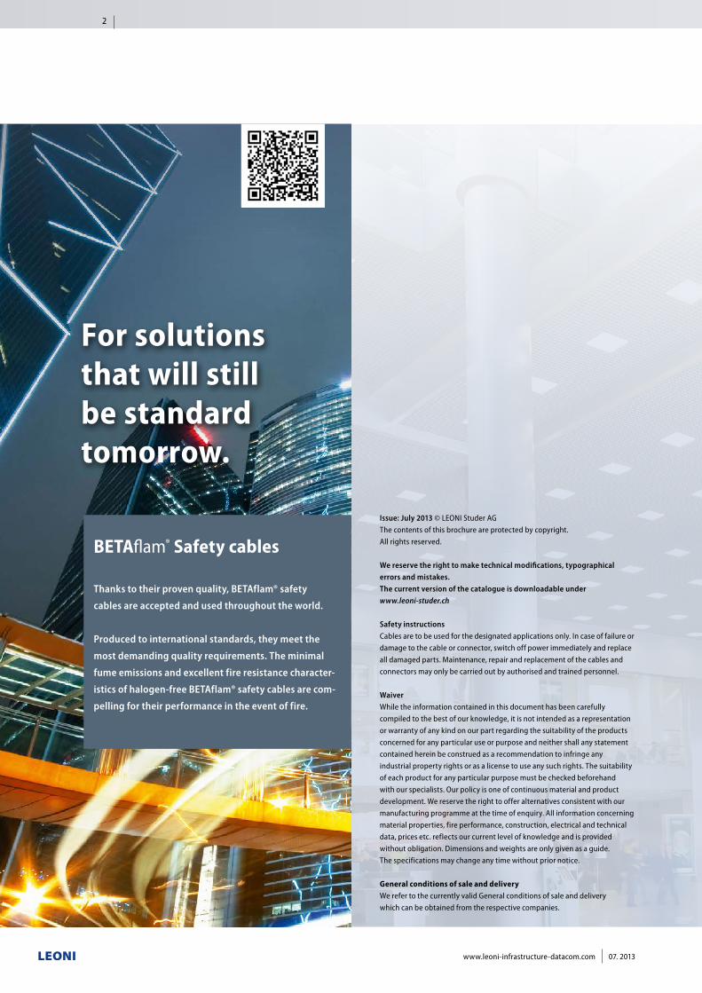
BETAflam® Safety cables
Thanks to their proven quality, BETAflam® safety
cables are accepted and used throughout the world.
Produced to international standards, they meet the
most demanding quality requirements. The minimal
fume emissions and excellent fire resistance character-
istics of halogen-free BETAflam® safety cables are com-
pelling for their performance in the event of fire.
Issue: July 2013 © LEONI Studer AGThe contents of this brochure are protected by copyright. All rights reserved.
We reserve the right to make technical modifications, typographical errors and mistakes.The current version of the catalogue is downloadable under www.leoni-studer.ch
Safety instructionsCables are to be used for the designated applications only. In case of failure or damage to the cable or connector, switch off power immediately and replace all damaged parts. Maintenance, repair and replacement of the cables and connectors may only be carried out by authorised and trained personnel.
WaiverWhile the information contained in this document has been carefully compiled to the best of our knowledge, it is not intended as a representation or warranty of any kind on our part regarding the suitability of the products concerned for any particular use or purpose and neither shall any statement contained herein be construed as a recommendation to infringe any industrial property rights or as a license to use any such rights. The suitability of each product for any particular purpose must be checked beforehand with our specialists. Our policy is one of continuous material and product development. We reserve the right to offer alternatives consistent with our manufacturing programme at the time of enquiry. All information concerning material properties, fire performance, construction, electrical and technical data, prices etc. reflects our current level of knowledge and is provided without obligation. Dimensions and weights are only given as a guide. The specifications may change any time without prior notice.
General conditions of sale and deliveryWe refer to the currently valid General conditions of sale and delivery which can be obtained from the respective companies.
For solutions that will still be standard tomorrow.
2
www.leoni-infrastructure-datacom.com 07. 2013
page
The LEONI Group 4
Future-proof all-in solutions 5
Great brands, great service 6
Green Technology 8
Technologies – investments in sustainable safety 10
Safety cables 12
Safety cables at a glance 14
Safety cables 16
Signal and fire alarm cables 26
Swiss standard cables 36
Connection cables 47
Connection cables for motors 50
Medium voltage single-core cables 55
Signal and fire alarm cables 57
Power cables 59
Installation cables 64
Technical informations 66
Current rating 68
Fire load 70
Core identification acc. to HD 308 S2 72
Halogen-free 73
Degree of acidity of combustion gases 73
Smoke density 74
Flame retardant 74
No flame propagation 75
Circuit integrity under fire 75Fire performance according to CPR
(Construction Product Regulation)76
Circuit integrity with mechanical shock 78
System integrity 78
Duration of system circuit integrity in the building 79
BETAflam® Approvals 80
BETAfixss® Cable support system at a glance 82
Further products 83
3
07. 2013 www.leoni-infrastructure-datacom.com
Automotive &
Commercial Vehicles
Communication &
Infrastructure
Industry &
HealthcareElectrical
Appliances
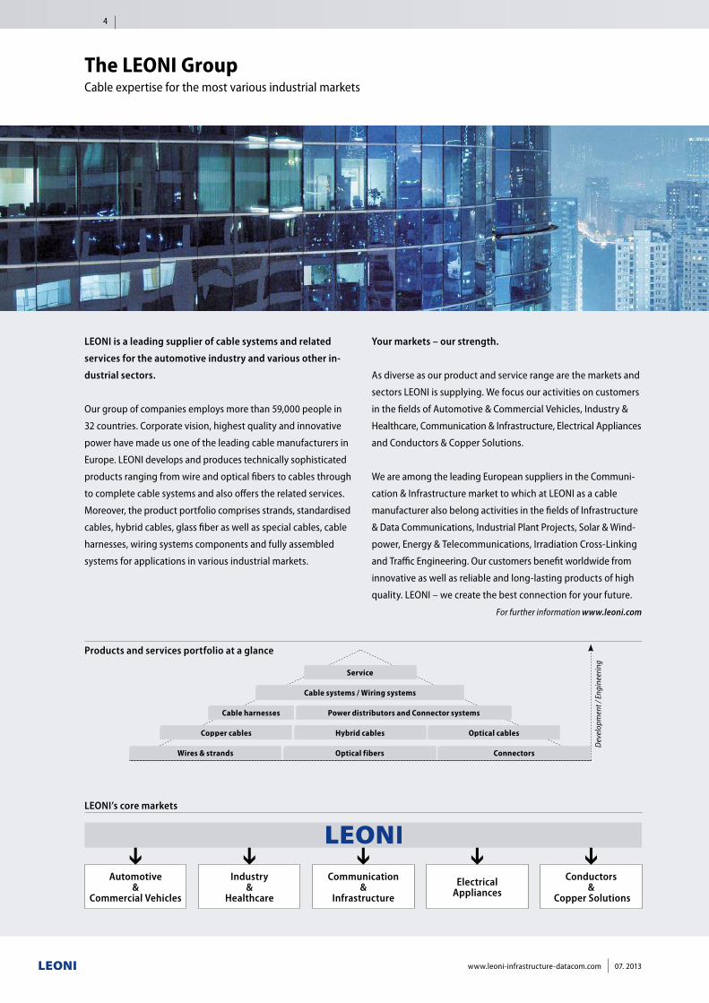
LEONI’s core markets
Products and services portfolio at a glance
LEONI is a leading supplier of cable systems and related
services for the automotive industry and various other in-
dustrial sectors.
Our group of companies employs more than 59,000 people in
32 countries. Corporate vision, highest quality and innovative
power have made us one of the leading cable manufacturers in
Europe. LEONI develops and produces technically sophisticated
products ranging from wire and optical fibers to cables through
to complete cable systems and also offers the related services.
Moreover, the product portfolio comprises strands, standardised
cables, hybrid cables, glass fiber as well as special cables, cable
harnesses, wiring systems components and fully assembled
systems for applications in various industrial markets.
Conductors &
Copper Solutions
Service
Optical cablesHybrid cablesCopper cables
Cable systems / Wiring systems
Power distributors and Connector systemsCable harnesses
ConnectorsOptical fibersWires & strands
Dev
elop
men
t / E
ngin
eerin
g
The LEONI Group Cable expertise for the most various industrial markets
Your markets – our strength.
As diverse as our product and service range are the markets and
sectors LEONI is supplying. We focus our activities on customers
in the fields of Automotive & Commercial Vehicles, Industry &
Healthcare, Communication & Infrastructure, Electrical Appliances
and Conductors & Copper Solutions.
We are among the leading European suppliers in the Communi-
cation & Infrastructure market to which at LEONI as a cable
manufacturer also belong activities in the fields of Infrastructure
& Data Communications, Industrial Plant Projects, Solar & Wind-
power, Energy & Telecommunications, Irradiation Cross-Linking
and Traffic Engineering. Our customers benefit worldwide from
innovative as well as reliable and long-lasting products of high
quality. LEONI – we create the best connection for your future.
For further information www.leoni.com
4
www.leoni-infrastructure-datacom.com 07. 2013
Business Unit Infrastructure & Datacom
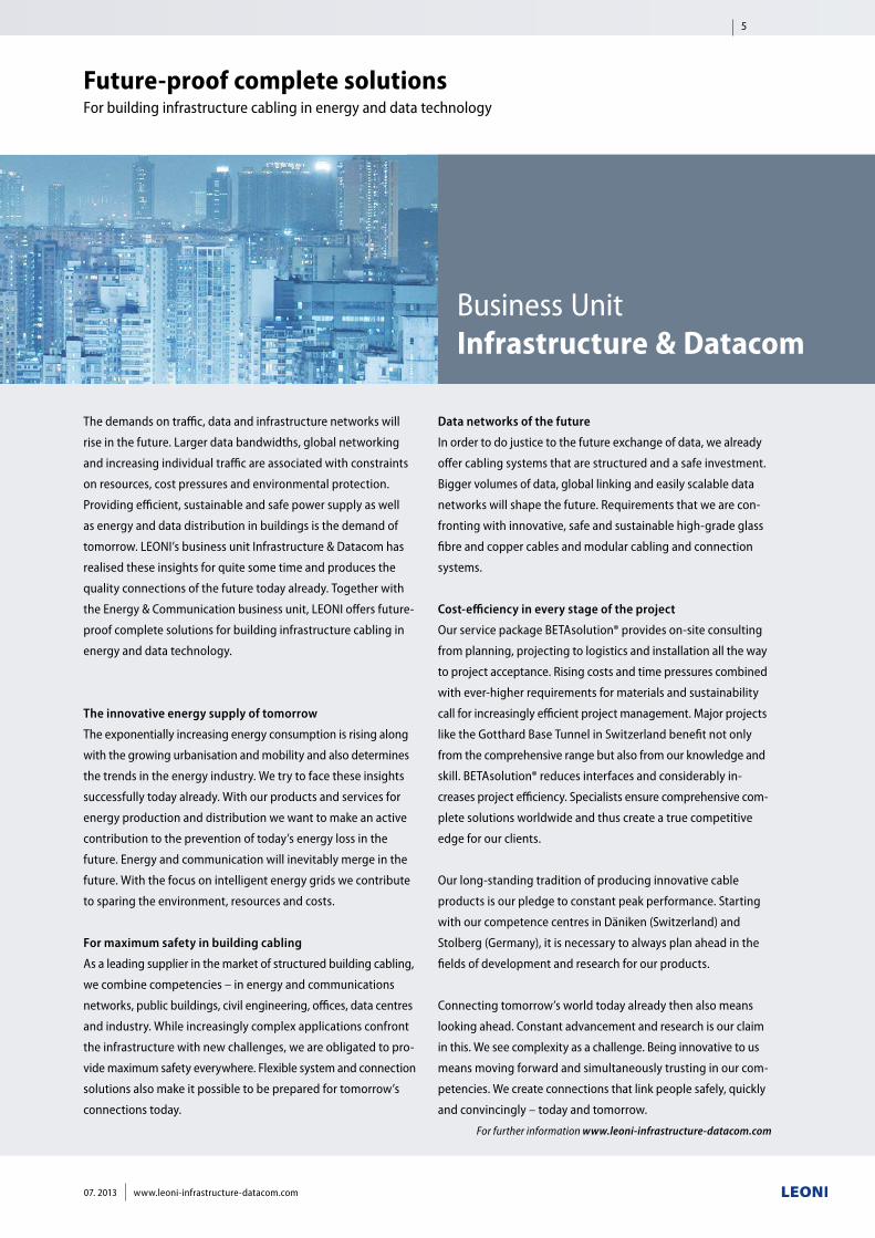
Future-proof complete solutions For building infrastructure cabling in energy and data technology
Data networks of the future
In order to do justice to the future exchange of data, we already
offer cabling systems that are structured and a safe investment.
Bigger volumes of data, global linking and easily scalable data
networks will shape the future. Requirements that we are con-
fronting with innovative, safe and sustainable high-grade glass
fibre and copper cables and modular cabling and connection
systems.
Cost-efficiency in every stage of the project
Our service package BETAsolution® provides on-site consulting
from planning, projecting to logistics and installation all the way
to project acceptance. Rising costs and time pressures combined
with ever-higher requirements for materials and sustainability
call for increasingly efficient project management. Major projects
like the Gotthard Base Tunnel in Switzerland benefit not only
from the comprehensive range but also from our knowledge and
skill. BETAsolution® reduces interfaces and considerably in-
creases project efficiency. Specialists ensure comprehensive com-
plete solutions worldwide and thus create a true competitive
edge for our clients.
Our long-standing tradition of producing innovative cable
products is our pledge to constant peak performance. Starting
with our competence centres in Däniken (Switzerland) and
Stolberg (Germany), it is necessary to always plan ahead in the
fields of development and research for our products.
Connecting tomorrow’s world today already then also means
looking ahead. Constant advancement and research is our claim
in this. We see complexity as a challenge. Being innovative to us
means moving forward and simultaneously trusting in our com-
petencies. We create connections that link people safely, quickly
and convincingly – today and tomorrow.
For further information www.leoni-infrastructure-datacom.com
The demands on traffic, data and infrastructure networks will
rise in the future. Larger data bandwidths, global networking
and increasing individual traffic are associated with constraints
on resources, cost pressures and environmental protection.
Providing efficient, sustainable and safe power supply as well
as energy and data distribution in buildings is the demand of
tomorrow. LEONI’s business unit Infrastructure & Datacom has
realised these insights for quite some time and produces the
quality connections of the future today already. Together with
the Energy & Communication business unit, LEONI offers future-
proof complete solutions for building infrastructure cabling in
energy and data technology.
The innovative energy supply of tomorrow
The exponentially increasing energy consumption is rising along
with the growing urbanisation and mobility and also determines
the trends in the energy industry. We try to face these insights
successfully today already. With our products and services for
energy production and distribution we want to make an active
contribution to the prevention of today’s energy loss in the
future. Energy and communication will inevitably merge in the
future. With the focus on intelligent energy grids we contribute
to sparing the environment, resources and costs.
For maximum safety in building cabling
As a leading supplier in the market of structured building cabling,
we combine competencies – in energy and communications
networks, public buildings, civil engineering, offices, data centres
and industry. While increasingly complex applications confront
the infrastructure with new challenges, we are obligated to pro-
vide maximum safety everywhere. Flexible system and connection
solutions also make it possible to be prepared for tomorrow’s
connections today.
5
07. 2013 www.leoni-infrastructure-datacom.com
Infrastructure –for maximum safety in cabling for buildings
Our products set the standard worldwide – in buildings, in under-
ground construction and in traffic infrastructure. Our cables
based on our proprietary patented design and production pro-
cesses ensure maximum safety and performance. The halogen-
free, fire-resistant insulation materials meet all the relevant stand-
ards while their extended service life also presents a com-
pelling advantage. Whether as laying systems or highly complex
network systems, our full infrastructure range convinces cust-
omers worldwide.
■■ BETAflam® according to the VDE standard Safety and installation cables
■■ BETAflam® according to the British Standard BS 6387 Safety and installation cables
■■ BETAfixss® with circuit integrity under fire acc. to DIN 4102 Certified installation systems
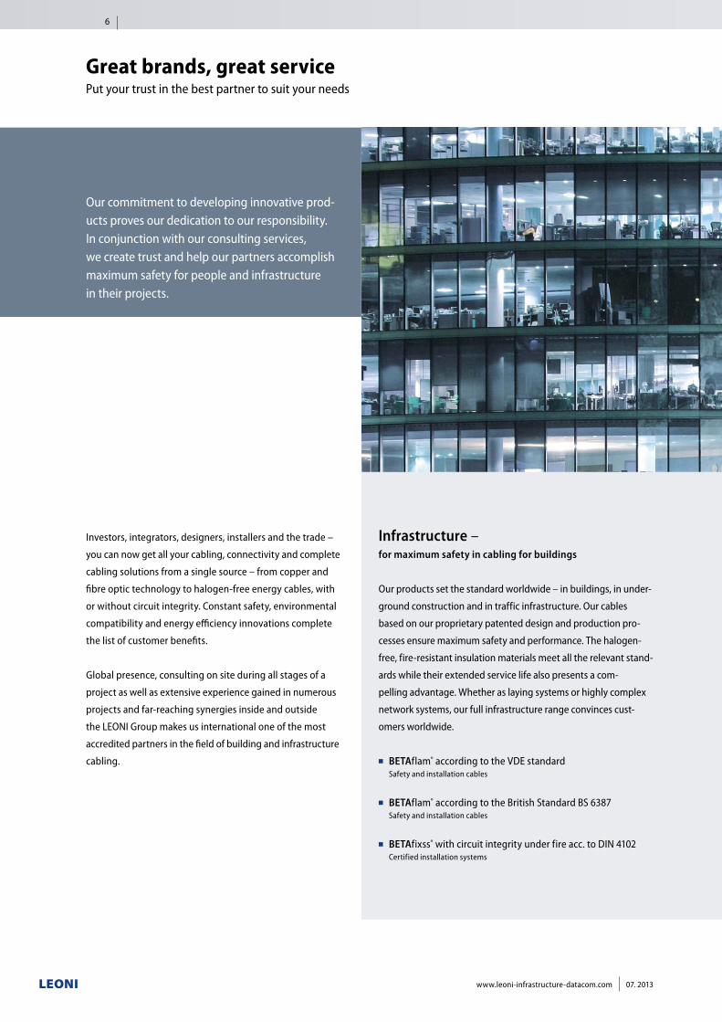
Our commitment to developing innovative prod-ucts proves our dedication to our responsibility. In conjunction with our consulting services,we create trust and help our partners accomplish maximum safety for people and infrastructurein their projects.
Great brands, great service Put your trust in the best partner to suit your needs
Investors, integrators, designers, installers and the trade –
you can now get all your cabling, connectivity and complete
cabling solutions from a single source – from copper and
fibre optic technology to halogen-free energy cables, with
or without circuit integrity. Constant safety, environmental
compatibility and energy efficiency innovations complete
the list of customer benefits.
Global presence, consulting on site during all stages of a
project as well as extensive experience gained in numerous
projects and far-reaching synergies inside and outside
the LEONI Group makes us international one of the most
accredited partners in the field of building and infrastructure
cabling.
6
www.leoni-infrastructure-datacom.com 07. 2013
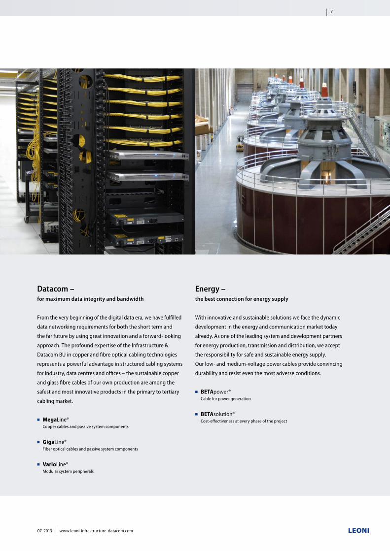
Datacom – for maximum data integrity and bandwidth
From the very beginning of the digital data era, we have fulfilled
data networking requirements for both the short term and
the far future by using great innovation and a forward-looking
approach. The profound expertise of the Infrastructure &
Datacom BU in copper and fibre optical cabling technologies
represents a powerful advantage in structured cabling systems
for industry, data centres and offices – the sustainable copper
and glass fibre cables of our own production are among the
safest and most innovative products in the primary to tertiary
cabling market.
■ MegaLine® Copper cables and passive system components
■ GigaLine® Fiber optical cables and passive system components
■ VarioLine® Modular system peripherals
Energy – the best connection for energy supply
With innovative and sustainable solutions we face the dynamic
development in the energy and communication market today
already. As one of the leading system and development partners
for energy production, transmission and distribution, we accept
the responsibility for safe and sustainable energy supply.
Our low- and medium-voltage power cables provide convincing
durability and resist even the most adverse conditions.
■ BETApower® Cable for power generation
■ BETAsolution® Cost-effectiveness at every phase of the project
7
07. 2013 www.leoni-infrastructure-datacom.com
Our vision is to create sustainable connections in technological
harmony with the natural resources. The cycle of nature gives
us the best model to emulate. It is our responsibility to learn
from nature and make use of it while conserving it and treating
it with care. The growing scarcity of the natural resources and
the increasing burden on the environment require a rethink
on all levels of society. For LEONI, sustainability is an integral
part of group policy. We are the first cable manufacturer in the
world to develop a holistic concept for “green technology”.
While trends like globalisation, mobility and urbanisation also
determine the markets, sustainability and global responsibility
are a central credo. To be considered the most innovative cable
manufacturer for environmentally friendly technologies – that
is our goal. At that, it is of vital interest to us to detect the needs
and requirements of tomorrow today and supply the markets
of the future with sustainable, future-proof solutions.
Green technology stands for the resource-conserving and low-
emission production of sustainable quality cables made with
low-pollution elements. We constantly work at optimising the
efficiency with which resources are used in the manufacturing
process by deploying energy-efficient machines or taking heat
recovery measures. More and more locations in our global pro-
duction network are environmentally certified according to the
ISO 14001 standard.
As a worldwide active and leading European supplier of wires,
optical fibres, cables and cable systems for communication and
infrastructure projects it is our responsibility to constantly opti-
mise the sustainability and durability of our products, system
solutions and services and thus lower the environmental load.
We have to increase the amount of environmentally compatible
raw materials in our cable products as well as the recyclability
of processed materials or components and in doing so create
end products that are developed for the environmental stand-
ard of tomorrow today.
In conjunction with the ecological compatibility, future tech-
nologies are measured in terms of efficiency, service life, emis-
sion reduction and the conservation of natural resources.
Innovative cable products and systems, holistic solutions and
maximum performance in project management are the added
value which we offer to our customers and business partners.
These are also our cornerstones for strong connections into the
future.
Green Technology Our company aim is to combine innovation with sustainability.
8
www.leoni-infrastructure-datacom.com 07. 2013
EU Directive 2002/96/EC
on waste electrical and electronic equipment.
EU Directive 2011/65/EU
on the restriction of the use of certain
hazardous substances in electrical and
electronic equipment.
What does RoHS mean?
RoHS stands for Restriction of the use of certain
Hazardous Substances in electrical and electronic
equipment.
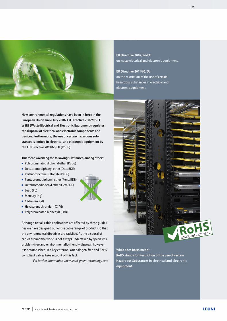
New environmental regulations have been in force in the
European Union since July 2006. EU Directive 2002/96/EC
WEEE (Waste Electrical and Electronic Equipment) regulates
the disposal of electrical and electronic components and
devices. Furthermore, the use of certain hazardous sub-
stances is limited in electrical and electronic equipment by
the EU Directive 2011/65/EU (RoHS).
This means avoiding the following substances, among others:■■ Polybrominated diphenyl ether (PBDE)■■ Decabromodiphenyl ether (DecaBDE)■■ Perfluorooctane sulfonate (PFOS)■■ Pentabromodiphenyl ether (PentaBDE)■■ Octabromodiphenyl ether (OctaBDE)■■ Lead (Pb)■■ Mercury (Hg)■■ Cadmium (Cd)■■ Hexavalent chromium (Cr VI)■■ Polybrominated biphenyls (PBB)
Although not all cable applications are affected by these guideli-
nes we have designed our entire cable range of products so that
the environmental directives are satisfied. As the disposal of
cables around the world is not always undertaken by specialists,
problem-free and environmentally-friendly disposal, however
it is accomplished, is a key criterion. Our halogen-free and RoHS
compliant cables take account of this fact.
For further information www.leoni-green-technology.com
9
07. 2013 www.leoni-infrastructure-datacom.com
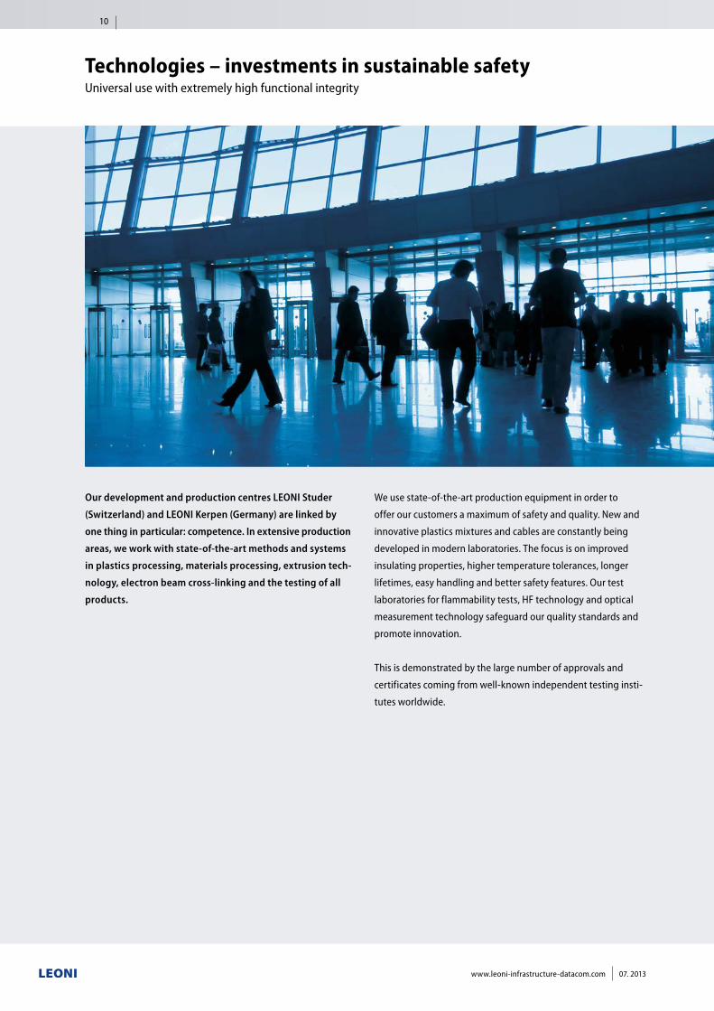
Technologies – investments in sustainable safety Universal use with extremely high functional integrity
Our development and production centres LEONI Studer
(Switzerland) and LEONI Kerpen (Germany) are linked by
one thing in particular: competence. In extensive production
areas, we work with state-of-the-art methods and systems
in plastics processing, materials processing, extrusion tech-
nology, electron beam cross-linking and the testing of all
products.
We use state-of-the-art production equipment in order to
offer our customers a maximum of safety and quality. New and
innovative plastics mixtures and cables are constantly being
developed in modern laboratories. The focus is on improved
insulating properties, higher temperature tolerances, longer
lifetimes, easy handling and better safety features. Our test
laboratories for flammability tests, HF technology and optical
measurement technology safeguard our quality standards and
promote innovation.
This is demonstrated by the large number of approvals and
certificates coming from well-known independent testing insti-
tutes worldwide.
10
www.leoni-infrastructure-datacom.com 07. 2013
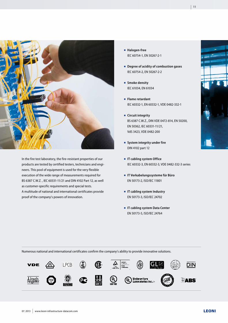
In the fire test laboratory, the fire-resistant properties of our
products are tested by certified testers, technicians and engi-
neers. This pool of equipment is used for the very flexible
execution of the wide range of measurements required for
BS 6387 C.W.Z. , IEC 60331-11/21 and DIN 4102 Part 12, as well
as customer-specific requirements and special tests.
A multitude of national and international certificates provide
proof of the company's powers of innovation.
■■ Halogen-free
IEC 60754-1, EN 50267-2-1
■■ Degree of acidity of combustion gases
IEC 60754-2, EN 50267-2-2
■■ Smoke density
IEC 61034, EN 61034
■■ Flame retardant
IEC 60332-1, EN 60332-1, VDE 0482-332-1
■■ Circuit integrity
BS 6387 C.W.Z., DIN VDE 0472-814, EN 50200,
EN 50362, IEC 60331-11/21,
VdS 3423, VDE 0482-200
■■ System integrity under fire
DIN 4102 part 12
■■ IT cabling system Office
IEC 60332-3, EN 60332-3, VDE 0482-332-3 series
■■ IT Verkabelungssysteme für Büro
EN 50173-2, ISO/IEC 11801
■■ IT cabling system Industry
EN 50173-3, ISO/IEC 24702
■■ IT cabling system Data Center
EN 50173-5, ISO/IEC 24764
Numerous national and international certificates confirm the company’s ability to provide innovative solutions.
11
07. 2013 www.leoni-infrastructure-datacom.com
www.leoni-infrastructure-datacom.com 07. 2013
12
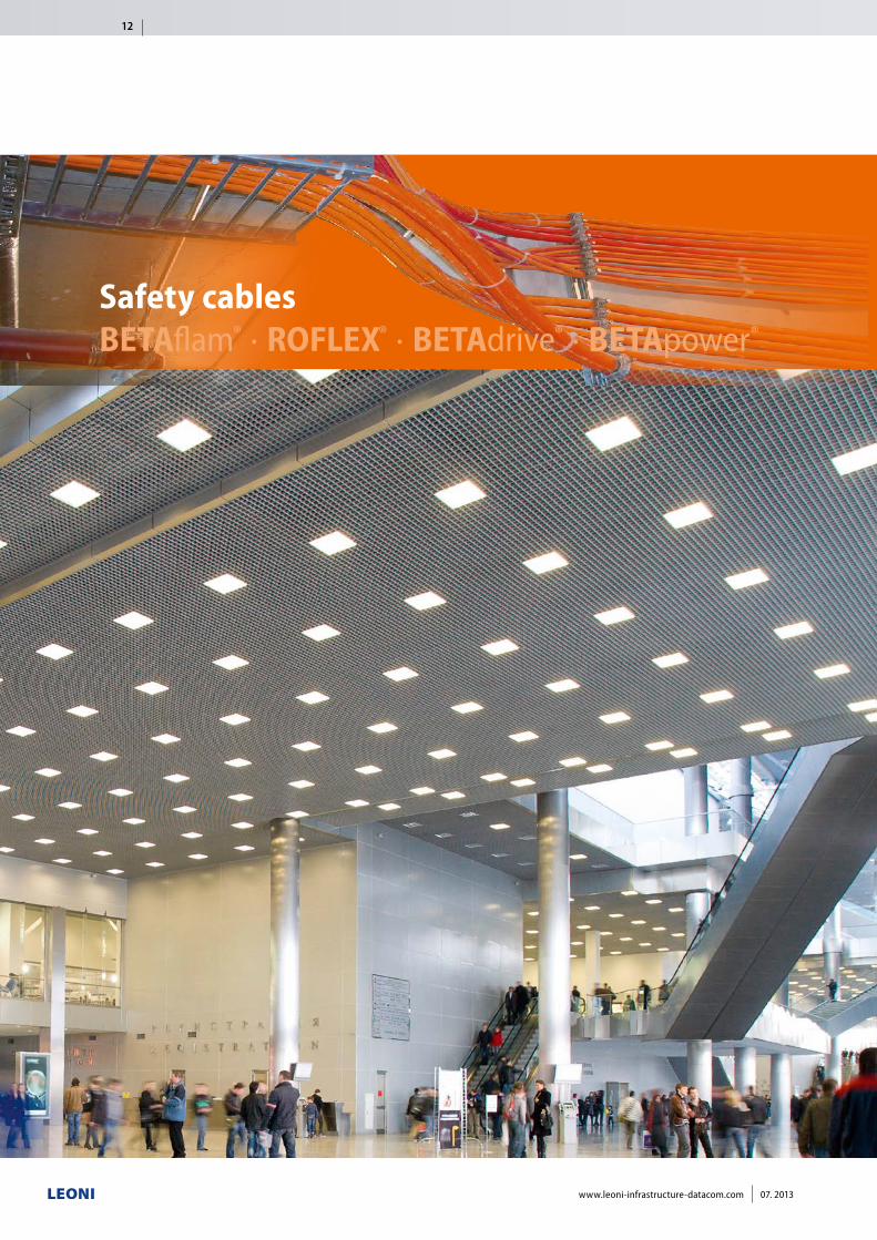
Safety cablesBETAflam® · ROFLEX® · BETAdrive® · BETApower®
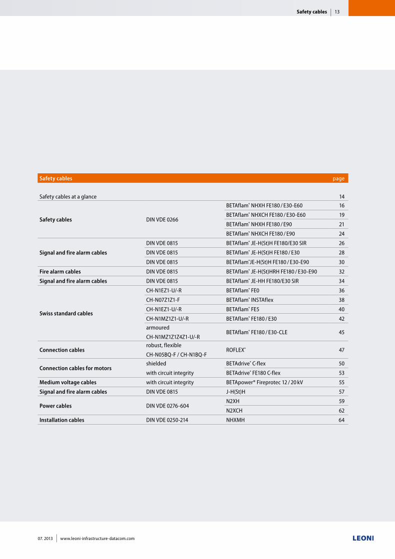
Safety cables page
Safety cables at a glance 14
Safety cables DIN VDE 0266
BETAflam® NHXH FE180 / E30-E60 16
BETAflam® NHXCH FE180 / E30-E60 19
BETAflam® NHXH FE180 / E90 21
BETAflam® NHXCH FE180 / E90 24
Signal and fire alarm cables
DIN VDE 0815 BETAflam® JE-H(St)H FE180/E30 SIR 26
DIN VDE 0815 BETAflam® JE-H(St)H FE180 / E30 28
DIN VDE 0815 BETAflam®JE-H(St)H FE180 / E30-E90 30
Fire alarm cables DIN VDE 0815 BETAflam® JE-H(St)HRH FE180 / E30-E90 32
Signal and fire alarm cables DIN VDE 0815 BETAflam® JE-HH FE180/E30 SIR 34
Swiss standard cables
CH-N1EZ1-U/-R BETAflam® FE0 36
CH-N07Z1Z1-F BETAflam® INSTAflex 38
CH-N1EZ1-U/-R BETAflam® FE5 40
CH-N1MZ1Z1-U/-R BETAflam® FE180 / E30 42armoured
CH-N1MZ1Z1Z4Z1-U/-RBETAflam® FE180 / E30-CLE 45
Connection cables robust, flexible
CH-N05BQ-F / CH-N1BQ-FROFLEX® 47
Connection cables for motors shielded
with circuit integrity
BETAdrive® C-flex 50
BETAdrive® FE180 C-flex 53
Medium voltage cables with circuit integrity BETApower® Fireprotec 12 / 20 kV 55
Signal and fire alarm cables DIN VDE 0815 J-H(St)H 57
Power cables DIN VDE 0276-604N2XH 59
N2XCH 62
Installation cables DIN VDE 0250-214 NHXMH 64
Safety cables 13
07. 2013 www.leoni-infrastructure-datacom.com
Safety cablesDIN VDE 0266
■■ BETAflam® NHXH FE180 / E30-E60
page 16
■■ BETAflam® NHXCH FE180 / E30-E60
page 19
■■ BETAflam® NHXH FE180 / E90
page 21
■■ BETAflam® NHXCH FE180 / E90
page 24
Signal and fire alarm cablesDIN VDE 0815
■■ BETAflam® JE-H(St)H FE180/E30 SIR
page 26
■■ BETAflam® JE-H(St)H FE180 / E30
page 28
■■ BETAflam® JE-H(St)H FE180 / E30-E90
page 30
■■ BETAflam® JE-H(St)HRH FE180 / E30-E90
page 32
■■ BETAflam® JE-HH FE180/E30 SIR
page 34
Swiss standard cables
■■ BETAflam® FE0
page 36
■■ BETAflam® INSTAflex
page 38
■■ BETAflam® FE5
page 40
■■ BETAflam® FE180 / E30
page 42
■■ BETAflam® FE180 / E30-CLE
page 45
■■ ROFLEX®
page 47
■■ BETAdrive® C-flex
page 50
■■ BETAdrive® FE180 C-flex
page 52
■■ BETApower® Fireprotec 12 / 20 kV
page 55
Further VDE cable types
■■ J-H(St)H
page 57
■■ N2XH
page 59
■■ N2XCH
page 62
■■ NHXMH
page 64
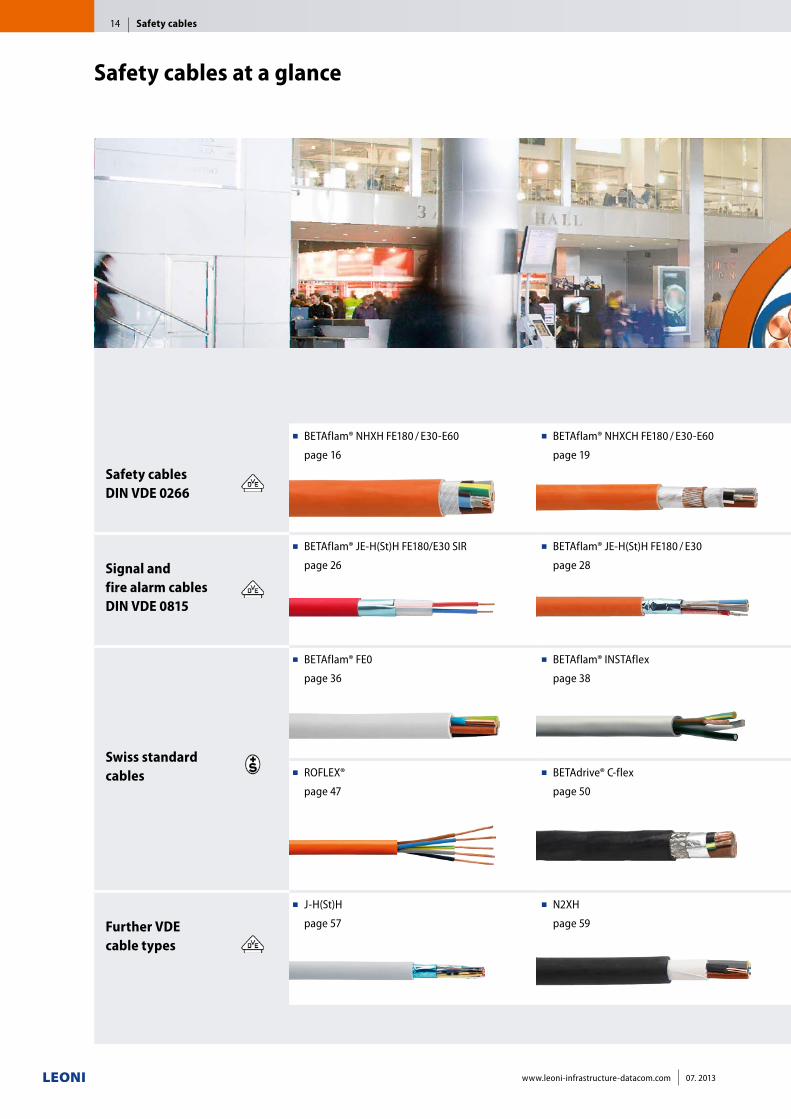
Safety cables at a glance
Safety cables14
www.leoni-infrastructure-datacom.com 07. 2013
Safety cablesDIN VDE 0266
■■ BETAflam® NHXH FE180 / E30-E60
page 16
■■ BETAflam® NHXCH FE180 / E30-E60
page 19
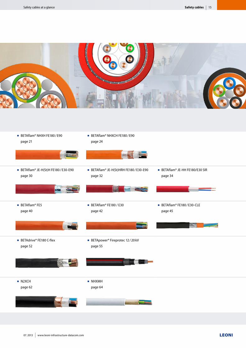
■■ BETAflam® NHXH FE180 / E90
page 21
■■ BETAflam® NHXCH FE180 / E90
page 24
Signal and fire alarm cablesDIN VDE 0815
■■ BETAflam® JE-H(St)H FE180/E30 SIR
page 26
■■ BETAflam® JE-H(St)H FE180 / E30
page 28
■■ BETAflam® JE-H(St)H FE180 / E30-E90
page 30
■■ BETAflam® JE-H(St)HRH FE180 / E30-E90
page 32
■■ BETAflam® JE-HH FE180/E30 SIR
page 34
Swiss standard cables
■■ BETAflam® FE0
page 36
■■ BETAflam® INSTAflex
page 38
■■ BETAflam® FE5
page 40
■■ BETAflam® FE180 / E30
page 42
■■ BETAflam® FE180 / E30-CLE
page 45
■■ ROFLEX®
page 47
■■ BETAdrive® C-flex
page 50
■■ BETAdrive® FE180 C-flex
page 52
■■ BETApower® Fireprotec 12 / 20 kV
page 55
Further VDE cable types
■■ J-H(St)H
page 57
■■ N2XH
page 59
■■ N2XCH
page 62
■■ NHXMH
page 64
Safety cables 15
07. 2013 www.leoni-infrastructure-datacom.com
Safety cables at a glance
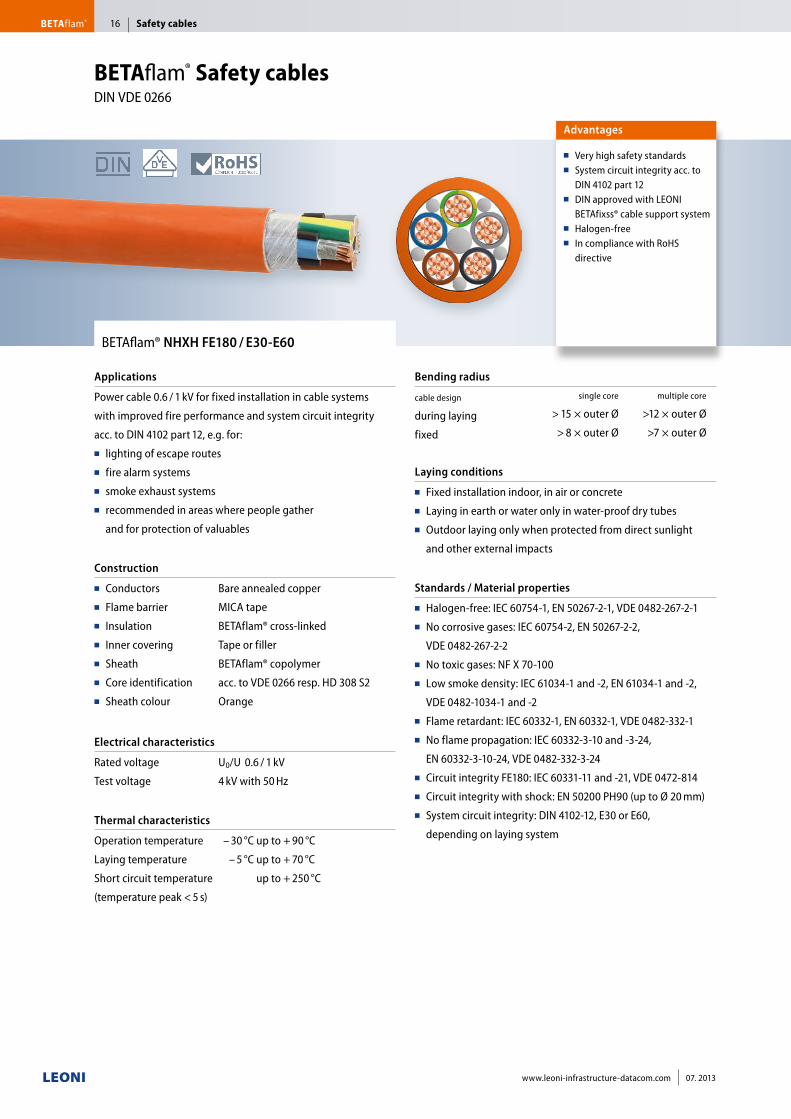
BETAflam® NHXH FE180 / E30-E60
Applications
Power cable 0.6 / 1 kV for fixed installation in cable systems
with improved fire performance and system circuit integrity
acc. to DIN 4102 part 12, e.g. for:■■ lighting of escape routes■■ fire alarm systems■■ smoke exhaust systems ■■ recommended in areas where people gather
and for protection of valuables
Construction
■■ Conductors■■ Flame barrier■■ Insulation■■ Inner covering■■ Sheath■■ Core identification■■ Sheath colour
Bare annealed copper
MICA tape
BETAflam® cross-linked
Tape or filler
BETAflam® copolymer
acc. to VDE 0266 resp. HD 308 S2
Orange
Electrical characteristics
Rated voltage
Test voltage
U0/U 0.6 / 1 kV
4 kV with 50 Hz
Thermal characteristics
Operation temperature
Laying temperature
Short circuit temperature
(temperature peak < 5 s)
– 30 °C up to + 90 °C
– 5 °C up to + 70 °C
up to + 250 °C
Bending radius
cable design
during laying
fixed
single core multiple core
> 15 × outer Ø >12 × outer Ø
> 8 × outer Ø >7 × outer Ø
Laying conditions
■■ Fixed installation indoor, in air or concrete■■ Laying in earth or water only in water-proof dry tubes■■ Outdoor laying only when protected from direct sunlight
and other external impacts
Standards / Material properties
■■ Halogen-free: IEC 60754-1, EN 50267-2-1, VDE 0482-267-2-1■■ No corrosive gases: IEC 60754-2, EN 50267-2-2,
VDE 0482-267-2-2■■ No toxic gases: NF X 70-100■■ Low smoke density: IEC 61034-1 and -2, EN 61034-1 and -2,
VDE 0482-1034-1 and -2■■ Flame retardant: IEC 60332-1, EN 60332-1, VDE 0482-332-1■■ No flame propagation: IEC 60332-3-10 and -3-24,
EN 60332-3-10-24, VDE 0482-332-3-24■■ Circuit integrity FE180: IEC 60331-11 and -21, VDE 0472-814■■ Circuit integrity with shock: EN 50200 PH90 (up to Ø 20 mm)■■ System circuit integrity: DIN 4102-12, E30 or E60,
depending on laying system
Advantages
■■ Very high safety standards■■ System circuit integrity acc. to
DIN 4102 part 12■■ DIN approved with LEONI
BETAfixss® cable support system■■ Halogen-free ■■ In compliance with RoHS
directive
BETAflam® Safety cables DIN VDE 0266
Safety cablesBETAflam® 16
www.leoni-infrastructure-datacom.com 07. 2013
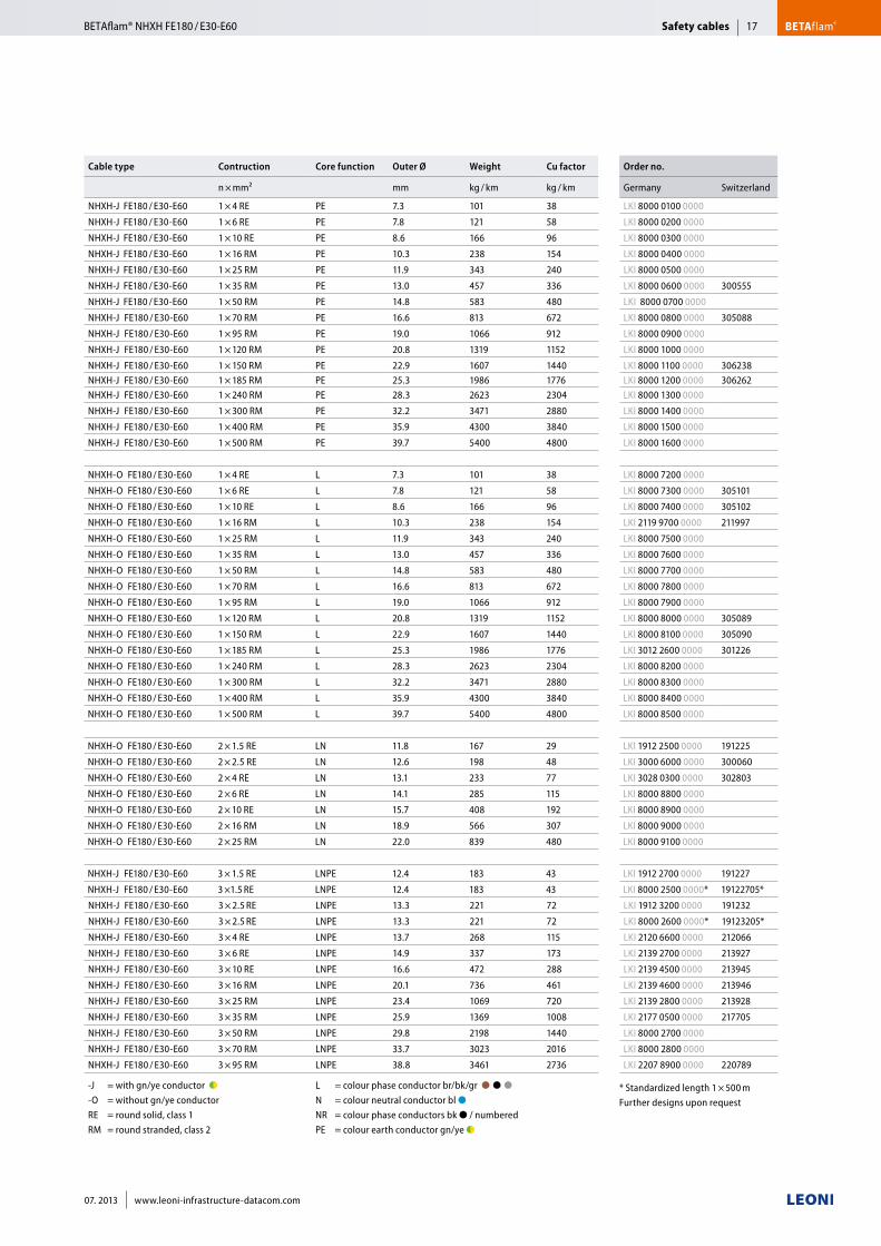
Cable type Contruction Core function Outer Ø Weight Cu factor Order no.
n × mm² mm kg / km kg / km Germany Switzerland
NHXH-J FE180 / E30-E60 1 × 4 RE PE 7.3 101 38 LKI 8000 0100 0000
NHXH-J FE180 / E30-E60 1 × 6 RE PE 7.8 121 58 LKI 8000 0200 0000
NHXH-J FE180 / E30-E60 1 × 10 RE PE 8.6 166 96 LKI 8000 0300 0000
NHXH-J FE180 / E30-E60 1 × 16 RM PE 10.3 238 154 LKI 8000 0400 0000
NHXH-J FE180 / E30-E60 1 × 25 RM PE 11.9 343 240 LKI 8000 0500 0000
NHXH-J FE180 / E30-E60 1 × 35 RM PE 13.0 457 336 LKI 8000 0600 0000 300555
NHXH-J FE180 / E30-E60 1 × 50 RM PE 14.8 583 480 LKI 8000 0700 0000
NHXH-J FE180 / E30-E60 1 × 70 RM PE 16.6 813 672 LKI 8000 0800 0000 305088
NHXH-J FE180 / E30-E60 1 × 95 RM PE 19.0 1066 912 LKI 8000 0900 0000
NHXH-J FE180 / E30-E60 1 × 120 RM PE 20.8 1319 1152 LKI 8000 1000 0000
NHXH-J FE180 / E30-E60 1 × 150 RM PE 22.9 1607 1440 LKI 8000 1100 0000 306238NHXH-J FE180 / E30-E60 1 × 185 RM PE 25.3 1986 1776 LKI 8000 1200 0000 306262NHXH-J FE180 / E30-E60 1 × 240 RM PE 28.3 2623 2304 LKI 8000 1300 0000
NHXH-J FE180 / E30-E60 1 × 300 RM PE 32.2 3471 2880 LKI 8000 1400 0000
NHXH-J FE180 / E30-E60 1 × 400 RM PE 35.9 4300 3840 LKI 8000 1500 0000
NHXH-J FE180 / E30-E60 1 × 500 RM PE 39.7 5400 4800 LKI 8000 1600 0000
NHXH-O FE180 / E30-E60 1 × 4 RE L 7.3 101 38 LKI 8000 7200 0000
NHXH-O FE180 / E30-E60 1 × 6 RE L 7.8 121 58 LKI 8000 7300 0000 305101
NHXH-O FE180 / E30-E60 1 × 10 RE L 8.6 166 96 LKI 8000 7400 0000 305102
NHXH-O FE180 / E30-E60 1 × 16 RM L 10.3 238 154 LKI 2119 9700 0000 211997
NHXH-O FE180 / E30-E60 1 × 25 RM L 11.9 343 240 LKI 8000 7500 0000
NHXH-O FE180 / E30-E60 1 × 35 RM L 13.0 457 336 LKI 8000 7600 0000
NHXH-O FE180 / E30-E60 1 × 50 RM L 14.8 583 480 LKI 8000 7700 0000
NHXH-O FE180 / E30-E60 1 × 70 RM L 16.6 813 672 LKI 8000 7800 0000
NHXH-O FE180 / E30-E60 1 × 95 RM L 19.0 1066 912 LKI 8000 7900 0000
NHXH-O FE180 / E30-E60 1 × 120 RM L 20.8 1319 1152 LKI 8000 8000 0000 305089
NHXH-O FE180 / E30-E60 1 × 150 RM L 22.9 1607 1440 LKI 8000 8100 0000 305090
NHXH-O FE180 / E30-E60 1 × 185 RM L 25.3 1986 1776 LKI 3012 2600 0000 301226
NHXH-O FE180 / E30-E60 1 × 240 RM L 28.3 2623 2304 LKI 8000 8200 0000
NHXH-O FE180 / E30-E60 1 × 300 RM L 32.2 3471 2880 LKI 8000 8300 0000
NHXH-O FE180 / E30-E60 1 × 400 RM L 35.9 4300 3840 LKI 8000 8400 0000
NHXH-O FE180 / E30-E60 1 × 500 RM L 39.7 5400 4800 LKI 8000 8500 0000
NHXH-O FE180 / E30-E60 2 × 1.5 RE LN 11.8 167 29 LKI 1912 2500 0000 191225
NHXH-O FE180 / E30-E60 2 × 2.5 RE LN 12.6 198 48 LKI 3000 6000 0000 300060
NHXH-O FE180 / E30-E60 2 × 4 RE LN 13.1 233 77 LKI 3028 0300 0000 302803
NHXH-O FE180 / E30-E60 2 × 6 RE LN 14.1 285 115 LKI 8000 8800 0000
NHXH-O FE180 / E30-E60 2 × 10 RE LN 15.7 408 192 LKI 8000 8900 0000
NHXH-O FE180 / E30-E60 2 × 16 RM LN 18.9 566 307 LKI 8000 9000 0000
NHXH-O FE180 / E30-E60 2 × 25 RM LN 22.0 839 480 LKI 8000 9100 0000
NHXH-J FE180 / E30-E60 3 × 1.5 RE LNPE 12.4 183 43 LKI 1912 2700 0000 191227
NHXH-J FE180 / E30-E60 3 ×1.5 RE LNPE 12.4 183 43 LKI 8000 2500 0000* 19122705*
NHXH-J FE180 / E30-E60 3 × 2.5 RE LNPE 13.3 221 72 LKI 1912 3200 0000 191232
NHXH-J FE180 / E30-E60 3 × 2.5 RE LNPE 13.3 221 72 LKI 8000 2600 0000* 19123205*
NHXH-J FE180 / E30-E60 3 × 4 RE LNPE 13.7 268 115 LKI 2120 6600 0000 212066
NHXH-J FE180 / E30-E60 3 × 6 RE LNPE 14.9 337 173 LKI 2139 2700 0000 213927
NHXH-J FE180 / E30-E60 3 × 10 RE LNPE 16.6 472 288 LKI 2139 4500 0000 213945
NHXH-J FE180 / E30-E60 3 × 16 RM LNPE 20.1 736 461 LKI 2139 4600 0000 213946
NHXH-J FE180 / E30-E60 3 × 25 RM LNPE 23.4 1069 720 LKI 2139 2800 0000 213928
NHXH-J FE180 / E30-E60 3 × 35 RM LNPE 25.9 1369 1008 LKI 2177 0500 0000 217705
NHXH-J FE180 / E30-E60 3 × 50 RM LNPE 29.8 2198 1440 LKI 8000 2700 0000
NHXH-J FE180 / E30-E60 3 × 70 RM LNPE 33.7 3023 2016 LKI 8000 2800 0000
NHXH-J FE180 / E30-E60 3 × 95 RM LNPE 38.8 3461 2736 LKI 2207 8900 0000 220789
-J = with gn/ye conductor ●◗ ■■ -O = without gn/ye conductor ■ RE = round solid, class 1 RM = round stranded, class 2
L = colour phase conductor br/bk/gr ●■●■●■■ N = colour neutral conductor bl ●■■ NR = colour phase conductors bk ● / numbered PE = colour earth conductor gn/ye ●◗
* Standardized length 1 × 500 mFurther designs upon request
Safety cables BETAflam®BETAflam® NHXH FE180 / E30-E60 17
07. 2013 www.leoni-infrastructure-datacom.com
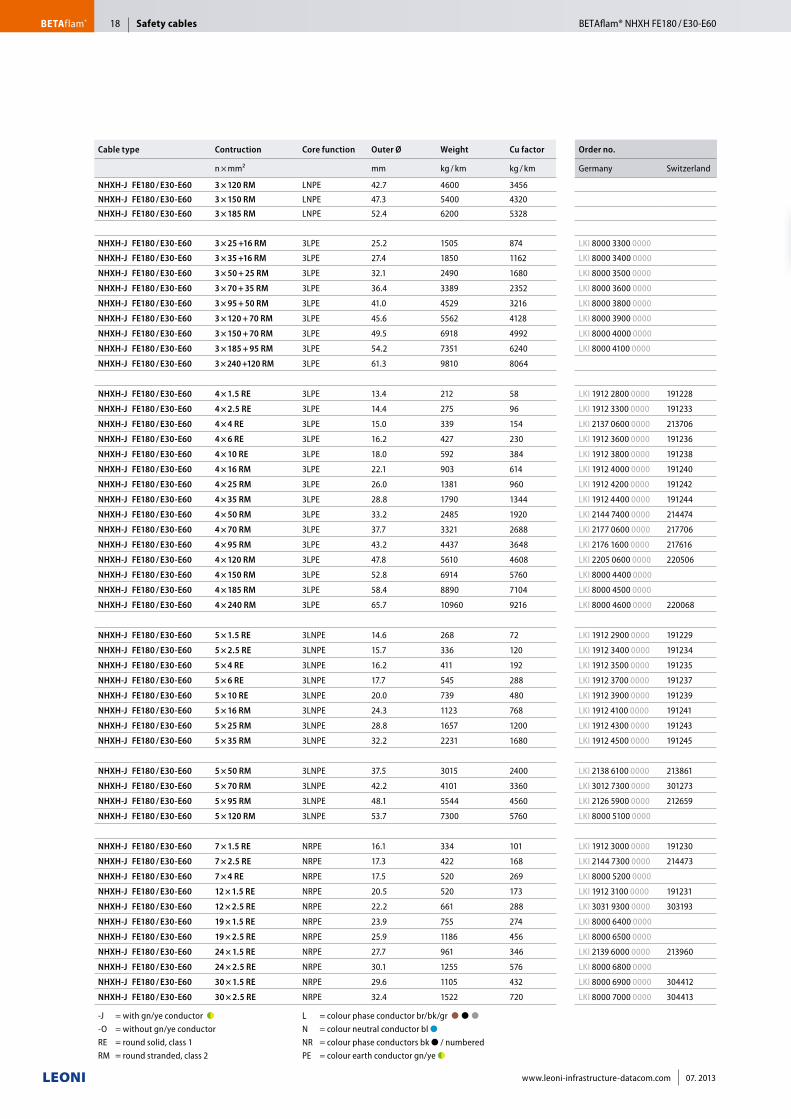
Cable type Contruction Core function Outer Ø Weight Cu factor Order no.
n × mm² mm kg / km kg / km Germany Switzerland
NHXH-J FE180 / E30-E60 3 × 120 RM LNPE 42.7 4600 3456
NHXH-J FE180 / E30-E60 3 × 150 RM LNPE 47.3 5400 4320
NHXH-J FE180 / E30-E60 3 × 185 RM LNPE 52.4 6200 5328
NHXH-J FE180 / E30-E60 3 × 25 +16 RM 3LPE 25.2 1505 874 LKI 8000 3300 0000
NHXH-J FE180 / E30-E60 3 × 35 +16 RM 3LPE 27.4 1850 1162 LKI 8000 3400 0000
NHXH-J FE180 / E30-E60 3 × 50 + 25 RM 3LPE 32.1 2490 1680 LKI 8000 3500 0000
NHXH-J FE180 / E30-E60 3 × 70 + 35 RM 3LPE 36.4 3389 2352 LKI 8000 3600 0000
NHXH-J FE180 / E30-E60 3 × 95 + 50 RM 3LPE 41.0 4529 3216 LKI 8000 3800 0000
NHXH-J FE180 / E30-E60 3 × 120 + 70 RM 3LPE 45.6 5562 4128 LKI 8000 3900 0000
NHXH-J FE180 / E30-E60 3 × 150 + 70 RM 3LPE 49.5 6918 4992 LKI 8000 4000 0000
NHXH-J FE180 / E30-E60 3 × 185 + 95 RM 3LPE 54.2 7351 6240 LKI 8000 4100 0000
NHXH-J FE180 / E30-E60 3 × 240 +120 RM 3LPE 61.3 9810 8064
NHXH-J FE180 / E30-E60 4 × 1.5 RE 3LPE 13.4 212 58 LKI 1912 2800 0000 191228
NHXH-J FE180 / E30-E60 4 × 2.5 RE 3LPE 14.4 275 96 LKI 1912 3300 0000 191233
NHXH-J FE180 / E30-E60 4 × 4 RE 3LPE 15.0 339 154 LKI 2137 0600 0000 213706
NHXH-J FE180 / E30-E60 4 × 6 RE 3LPE 16.2 427 230 LKI 1912 3600 0000 191236
NHXH-J FE180 / E30-E60 4 × 10 RE 3LPE 18.0 592 384 LKI 1912 3800 0000 191238
NHXH-J FE180 / E30-E60 4 × 16 RM 3LPE 22.1 903 614 LKI 1912 4000 0000 191240
NHXH-J FE180 / E30-E60 4 × 25 RM 3LPE 26.0 1381 960 LKI 1912 4200 0000 191242
NHXH-J FE180 / E30-E60 4 × 35 RM 3LPE 28.8 1790 1344 LKI 1912 4400 0000 191244
NHXH-J FE180 / E30-E60 4 × 50 RM 3LPE 33.2 2485 1920 LKI 2144 7400 0000 214474
NHXH-J FE180 / E30-E60 4 × 70 RM 3LPE 37.7 3321 2688 LKI 2177 0600 0000 217706
NHXH-J FE180 / E30-E60 4 × 95 RM 3LPE 43.2 4437 3648 LKI 2176 1600 0000 217616
NHXH-J FE180 / E30-E60 4 × 120 RM 3LPE 47.8 5610 4608 LKI 2205 0600 0000 220506
NHXH-J FE180 / E30-E60 4 × 150 RM 3LPE 52.8 6914 5760 LKI 8000 4400 0000
NHXH-J FE180 / E30-E60 4 × 185 RM 3LPE 58.4 8890 7104 LKI 8000 4500 0000
NHXH-J FE180 / E30-E60 4 × 240 RM 3LPE 65.7 10960 9216 LKI 8000 4600 0000 220068
NHXH-J FE180 / E30-E60 5 × 1.5 RE 3LNPE 14.6 268 72 LKI 1912 2900 0000 191229
NHXH-J FE180 / E30-E60 5 × 2.5 RE 3LNPE 15.7 336 120 LKI 1912 3400 0000 191234
NHXH-J FE180 / E30-E60 5 × 4 RE 3LNPE 16.2 411 192 LKI 1912 3500 0000 191235
NHXH-J FE180 / E30-E60 5 × 6 RE 3LNPE 17.7 545 288 LKI 1912 3700 0000 191237
NHXH-J FE180 / E30-E60 5 × 10 RE 3LNPE 20.0 739 480 LKI 1912 3900 0000 191239
NHXH-J FE180 / E30-E60 5 × 16 RM 3LNPE 24.3 1123 768 LKI 1912 4100 0000 191241
NHXH-J FE180 / E30-E60 5 × 25 RM 3LNPE 28.8 1657 1200 LKI 1912 4300 0000 191243
NHXH-J FE180 / E30-E60 5 × 35 RM 3LNPE 32.2 2231 1680 LKI 1912 4500 0000 191245
NHXH-J FE180 / E30-E60 5 × 50 RM 3LNPE 37.5 3015 2400 LKI 2138 6100 0000 213861
NHXH-J FE180 / E30-E60 5 × 70 RM 3LNPE 42.2 4101 3360 LKI 3012 7300 0000 301273
NHXH-J FE180 / E30-E60 5 × 95 RM 3LNPE 48.1 5544 4560 LKI 2126 5900 0000 212659
NHXH-J FE180 / E30-E60 5 × 120 RM 3LNPE 53.7 7300 5760 LKI 8000 5100 0000
NHXH-J FE180 / E30-E60 7 × 1.5 RE NRPE 16.1 334 101 LKI 1912 3000 0000 191230
NHXH-J FE180 / E30-E60 7 × 2.5 RE NRPE 17.3 422 168 LKI 2144 7300 0000 214473
NHXH-J FE180 / E30-E60 7 × 4 RE NRPE 17.5 520 269 LKI 8000 5200 0000
NHXH-J FE180 / E30-E60 12 × 1.5 RE NRPE 20.5 520 173 LKI 1912 3100 0000 191231
NHXH-J FE180 / E30-E60 12 × 2.5 RE NRPE 22.2 661 288 LKI 3031 9300 0000 303193
NHXH-J FE180 / E30-E60 19 × 1.5 RE NRPE 23.9 755 274 LKI 8000 6400 0000
NHXH-J FE180 / E30-E60 19 × 2.5 RE NRPE 25.9 1186 456 LKI 8000 6500 0000
NHXH-J FE180 / E30-E60 24 × 1.5 RE NRPE 27.7 961 346 LKI 2139 6000 0000 213960
NHXH-J FE180 / E30-E60 24 × 2.5 RE NRPE 30.1 1255 576 LKI 8000 6800 0000
NHXH-J FE180 / E30-E60 30 × 1.5 RE NRPE 29.6 1105 432 LKI 8000 6900 0000 304412
NHXH-J FE180 / E30-E60 30 × 2.5 RE NRPE 32.4 1522 720 LKI 8000 7000 0000 304413
-J = with gn/ye conductor ●◗ ■■ -O = without gn/ye conductor ■ RE = round solid, class 1 RM = round stranded, class 2
L = colour phase conductor br/bk/gr ●■●■●■■ N = colour neutral conductor bl ●■■ NR = colour phase conductors bk ● / numbered PE = colour earth conductor gn/ye ●◗
Safety cablesBETAflam® BETAflam® NHXH FE180 / E30-E6018
www.leoni-infrastructure-datacom.com 07. 2013
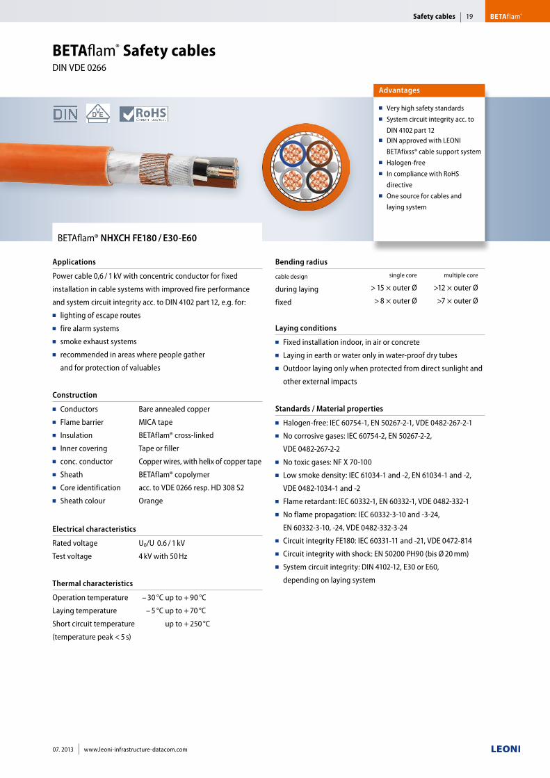
BETAflam® NHXCH FE180 / E30-E60
Applications
Power cable 0,6 / 1 kV with concentric conductor for fixed
installation in cable systems with improved fire performance
and system circuit integrity acc. to DIN 4102 part 12, e.g. for:■■ lighting of escape routes■■ fire alarm systems■■ smoke exhaust systems ■■ recommended in areas where people gather
and for protection of valuables
Construction
■■ Conductors■■ Flame barrier■■ Insulation■■ Inner covering■■ conc. conductor■■ Sheath■■ Core identification■■ Sheath colour
Bare annealed copper
MICA tape
BETAflam® cross-linked
Tape or filler
Copper wires, with helix of copper tape
BETAflam® copolymer
acc. to VDE 0266 resp. HD 308 S2
Orange
Electrical characteristics
Rated voltage
Test voltage
U0/U 0.6 / 1 kV
4 kV with 50 Hz
Thermal characteristics
Operation temperature
Laying temperature
Short circuit temperature
(temperature peak < 5 s)
– 30 °C up to + 90 °C
– 5 °C up to + 70 °C
up to + 250 °C
Bending radius
cable design
during laying
fixed
single core multiple core
> 15 × outer Ø >12 × outer Ø
> 8 × outer Ø >7 × outer Ø
Laying conditions
■■ Fixed installation indoor, in air or concrete■■ Laying in earth or water only in water-proof dry tubes■■ Outdoor laying only when protected from direct sunlight and
other external impacts
Standards / Material properties
■■ Halogen-free: IEC 60754-1, EN 50267-2-1, VDE 0482-267-2-1■■ No corrosive gases: IEC 60754-2, EN 50267-2-2,
VDE 0482-267-2-2■■ No toxic gases: NF X 70-100■■ Low smoke density: IEC 61034-1 and -2, EN 61034-1 and -2,
VDE 0482-1034-1 and -2■■ Flame retardant: IEC 60332-1, EN 60332-1, VDE 0482-332-1■■ No flame propagation: IEC 60332-3-10 and -3-24,
EN 60332-3-10, -24, VDE 0482-332-3-24■■ Circuit integrity FE180: IEC 60331-11 and -21, VDE 0472-814■■ Circuit integrity with shock: EN 50200 PH90 (bis Ø 20 mm)■■ System circuit integrity: DIN 4102-12, E30 or E60,
depending on laying system
Advantages
■■ Very high safety standards■■ System circuit integrity acc. to
DIN 4102 part 12■■ DIN approved with LEONI
BETAfixss® cable support system■■ Halogen-free■■ In compliance with RoHS
directive■■ One source for cables and
laying system
BETAflam® Safety cables DIN VDE 0266
Safety cables BETAflam®19
07. 2013 www.leoni-infrastructure-datacom.com
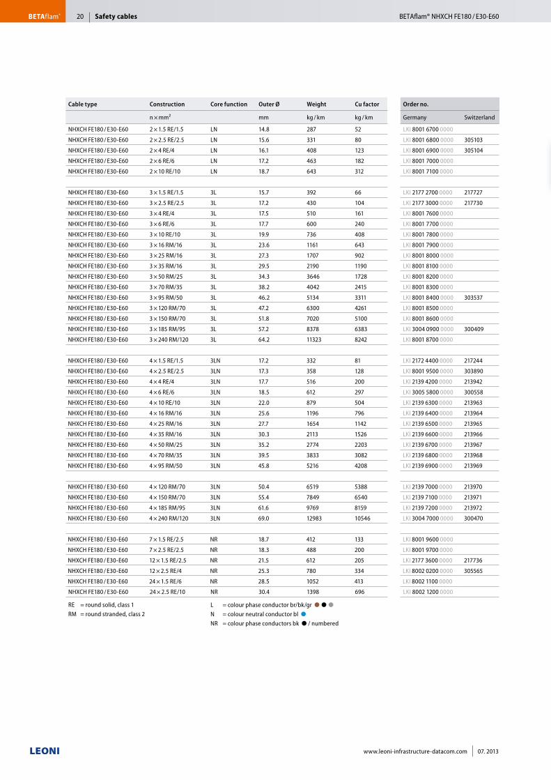
Cable type Construction Core function Outer Ø Weight Cu factor Order no.
n × mm² mm kg / km kg / km Germany Switzerland
NHXCH FE180 / E30-E60 2 × 1.5 RE/1.5 LN 14.8 287 52 LKI 8001 6700 0000
NHXCH FE180 / E30-E60 2 × 2.5 RE/2.5 LN 15.6 331 80 LKI 8001 6800 0000 305103
NHXCH FE180 / E30-E60 2 × 4 RE/4 LN 16.1 408 123 LKI 8001 6900 0000 305104
NHXCH FE180 / E30-E60 2 × 6 RE/6 LN 17.2 463 182 LKI 8001 7000 0000
NHXCH FE180 / E30-E60 2 × 10 RE/10 LN 18.7 643 312 LKI 8001 7100 0000
NHXCH FE180 / E30-E60 3 × 1.5 RE/1.5 3L 15.7 392 66 LKI 2177 2700 0000 217727
NHXCH FE180 / E30-E60 3 × 2.5 RE/2.5 3L 17.2 430 104 LKI 2177 3000 0000 217730
NHXCH FE180 / E30-E60 3 × 4 RE/4 3L 17.5 510 161 LKI 8001 7600 0000
NHXCH FE180 / E30-E60 3 × 6 RE/6 3L 17.7 600 240 LKI 8001 7700 0000
NHXCH FE180 / E30-E60 3 × 10 RE/10 3L 19.9 736 408 LKI 8001 7800 0000
NHXCH FE180 / E30-E60 3 × 16 RM/16 3L 23.6 1161 643 LKI 8001 7900 0000
NHXCH FE180 / E30-E60 3 × 25 RM/16 3L 27.3 1707 902 LKI 8001 8000 0000
NHXCH FE180 / E30-E60 3 × 35 RM/16 3L 29.5 2190 1190 LKI 8001 8100 0000
NHXCH FE180 / E30-E60 3 × 50 RM/25 3L 34.3 3646 1728 LKI 8001 8200 0000
NHXCH FE180 / E30-E60 3 × 70 RM/35 3L 38.2 4042 2415 LKI 8001 8300 0000
NHXCH FE180 / E30-E60 3 × 95 RM/50 3L 46.2 5134 3311 LKI 8001 8400 0000 303537
NHXCH FE180 / E30-E60 3 × 120 RM/70 3L 47.2 6300 4261 LKI 8001 8500 0000
NHXCH FE180 / E30-E60 3 × 150 RM/70 3L 51.8 7020 5100 LKI 8001 8600 0000
NHXCH FE180 / E30-E60 3 × 185 RM/95 3L 57.2 8378 6383 LKI 3004 0900 0000 300409
NHXCH FE180 / E30-E60 3 × 240 RM/120 3L 64.2 11323 8242 LKI 8001 8700 0000
NHXCH FE180 / E30-E60 4 × 1.5 RE/1.5 3LN 17.2 332 81 LKI 2172 4400 0000 217244
NHXCH FE180 / E30-E60 4 × 2.5 RE/2.5 3LN 17.3 358 128 LKI 8001 9500 0000 303890
NHXCH FE180 / E30-E60 4 × 4 RE/4 3LN 17.7 516 200 LKI 2139 4200 0000 213942
NHXCH FE180 / E30-E60 4 × 6 RE/6 3LN 18.5 612 297 LKI 3005 5800 0000 300558
NHXCH FE180 / E30-E60 4 × 10 RE/10 3LN 22.0 879 504 LKI 2139 6300 0000 213963
NHXCH FE180 / E30-E60 4 × 16 RM/16 3LN 25.6 1196 796 LKI 2139 6400 0000 213964
NHXCH FE180 / E30-E60 4 × 25 RM/16 3LN 27.7 1654 1142 LKI 2139 6500 0000 213965
NHXCH FE180 / E30-E60 4 × 35 RM/16 3LN 30.3 2113 1526 LKI 2139 6600 0000 213966
NHXCH FE180 / E30-E60 4 × 50 RM/25 3LN 35.2 2774 2203 LKI 2139 6700 0000 213967
NHXCH FE180 / E30-E60 4 × 70 RM/35 3LN 39.5 3833 3082 LKI 2139 6800 0000 213968
NHXCH FE180 / E30-E60 4 × 95 RM/50 3LN 45.8 5216 4208 LKI 2139 6900 0000 213969
NHXCH FE180 / E30-E60 4 × 120 RM/70 3LN 50.4 6519 5388 LKI 2139 7000 0000 213970
NHXCH FE180 / E30-E60 4 × 150 RM/70 3LN 55.4 7849 6540 LKI 2139 7100 0000 213971
NHXCH FE180 / E30-E60 4 × 185 RM/95 3LN 61.6 9769 8159 LKI 2139 7200 0000 213972
NHXCH FE180 / E30-E60 4 × 240 RM/120 3LN 69.0 12983 10546 LKI 3004 7000 0000 300470
NHXCH FE180 / E30-E60 7 × 1.5 RE/2.5 NR 18.7 412 133 LKI 8001 9600 0000
NHXCH FE180 / E30-E60 7 × 2.5 RE/2.5 NR 18.3 488 200 LKI 8001 9700 0000
NHXCH FE180 / E30-E60 12 × 1.5 RE/2.5 NR 21.5 612 205 LKI 2177 3600 0000 217736
NHXCH FE180 / E30-E60 12 × 2.5 RE/4 NR 25.3 780 334 LKI 8002 0200 0000 305565
NHXCH FE180 / E30-E60 24 × 1.5 RE/6 NR 28.5 1052 413 LKI 8002 1100 0000
NHXCH FE180 / E30-E60 24 × 2.5 RE/10 NR 30.4 1398 696 LKI 8002 1200 0000
RE = round solid, class 1 RM = round stranded, class 2
L = colour phase conductor br/bk/gr ●■●■●■■ N = colour neutral conductor bl ●■■ NR = colour phase conductors bk ● / numbered
Safety cablesBETAflam® BETAflam® NHXCH FE180 / E30-E6020
www.leoni-infrastructure-datacom.com 07. 2013
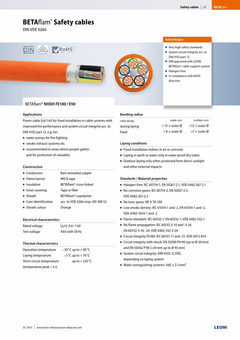
BETAflam® NHXH FE180 / E90
Applications
Power cable 0,6/1 kV for fixed installation in cable systems with
improved fire performance and system circuit integrity acc. to
DIN 4102 part 12, e.g. for:■■ water pumps for fire fighting■■ smoke exhaust systems etc. ■■ recommended in areas where people gather
and for protection of valuables
Construction
■■ Conductors■■ Flame barrier■■ Insulation■■ Inner covering■■ Sheath■■ Core identification■■ Sheath colour
Bare annealed copper
MICA tape
BETAflam® cross-linked
Tape or filler
BETAflam® copolymer
acc. to VDE 0266 resp. HD 308 S2
Orange
Electrical characteristics
Rated voltage
Test voltage
U0/U 0.6 / 1 kV
4 kV with 50 Hz
Thermal characteristics
Operation temperature
Laying temperature
Short circuit temperature
(temperature peak < 5 s)
– 30 °C up to + 90 °C
– 5 °C up to + 70 °C
up to + 250 °C
Bending radius
cable design
during laying
fixed
single core multiple core
> 15 × outer Ø >12 × outer Ø
> 8 × outer Ø >7 × outer Ø
Laying conditions
■■ Fixed installation indoor, in air or concrete■■ Laying in earth or water only in water-proof dry tubes■■ Outdoor laying only when protected from direct sunlight
and other external impacts
Standards / Material properties
■■ Halogen-free: IEC 60754-1, EN 50267-2-1, VDE 0482-267-2-1■■ No corrosive gases: IEC 60754-2, EN 50267-2-2,
VDE 0482-267-2-2■■ No toxic gases: NF X 70-100■■ Low smoke density: IEC 61034-1 and -2, EN 61034-1 and -2,
VDE 0482-1034-1 and -2■■ Flame retardant: IEC 60332-1, EN 60332-1, VDE 0482-332-1■■ No flame propagation: IEC 60332-3-10 and -3-24,
EN 60332-3-10, -24, VDE 0482-332-3-24■■ Circuit integrity FE180: IEC 60331-11 and -21, VDE 0472-814■■ Circuit integrity with shock: EN 50200 PH 90 (up to Ø 20 mm)
and EN 50362 P 90 (>20 mm up to Ø 45 mm)■■ System circuit integrity: DIN 4102-12 E90,
depending on laying system■■ Water extinguishing systems: VdS ≥ 2.5 mm²
Advantages
■■ Very high safety standards■■ System circuit integrity acc. to
DIN 4102 part 12■■ DIN approved with LEONI
BETAfixss® cable support system■■ Halogen-free■■ In compliance with RoHS
directive
BETAflam® Safety cables DIN VDE 0266
Safety cables BETAflam®21
07. 2013 www.leoni-infrastructure-datacom.com
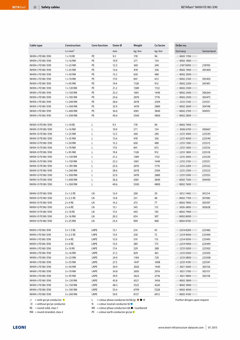
Cable type Construction Core function Outer Ø Weight Cu factor Order no.
n × mm² mm kg / km kg / km Germany Switzerland
NHXH-J FE180 / E90 1 × 10 RE PE 9.5 178 96 LKI 8002 1700 0000
NHXH-J FE180 / E90 1 × 16 RM PE 10.9 271 154 LKI 8002 1800 0000
NHXH-J FE180 / E90 1 × 25 RM PE 12.5 360 240 LKI 2187 8300 0000 218783
NHXH-J FE180 / E90 1 × 35 RM PE 13.6 478 336 LKI 8002 1900 0000 305400
NHXH-J FE180 / E90 1 × 50 RM PE 15.2 630 480 LKI 8002 2000 0000
NHXH-J FE180 / E90 1 × 70 RM PE 17.0 841 672 LKI 8002 2100 0000 305403
NHXH-J FE180 / E90 1 × 95 RM PE 19.4 1128 912 LKI 8002 2200 0000 305401
NHXH-J FE180 / E90 1 × 120 RM PE 21.2 1389 1152 LKI 8002 2300 0000
NHXH-J FE180 / E90 1 × 150 RM PE 23.2 1681 1440 LKI 8002 2400 0000 306264
NHXH-J FE180 / E90 1 × 185 RM PE 25.6 2070 1776 LKI 8002 2500 0000 303473
NHXH-J FE180 / E90 1 × 240 RM PE 28.6 2678 2304 LKI 2255 5100 0000 225551
NHXH-J FE180 / E90 1 × 300 RM PE 32.9 3478 2880 LKI 8002 2600 0000 304198
NHXH-J FE180 / E90 1 × 400 RM PE 36.6 4381 3840 LKI 8002 2700 0000 304931
NHXH-J FE180 / E90 1 × 500 RM PE 40.6 5500 4800 LKI 8002 2800 0000
NHXH-O FE180 / E90 1 × 10 RE L 9.5 178 96 LKI 8002 7400 0000
NHXH-O FE180 / E90 1 × 16 RM L 10.9 271 154 LKI 3006 6700 0000 300667
NHXH-O FE180 / E90 1 × 25 RM L 12.5 360 240 LKI 2255 3900 0000 225539
NHXH-O FE180 / E90 1 × 35 RM L 13.6 478 336 LKI 2255 4000 0000 225540
NHXH-O FE180 / E90 1 × 50 RM L 15.2 630 480 LKI 2255 1300 0000 225513
NHXH-O FE180 / E90 1 × 70 RM L 17.0 841 672 LKI 2255 1600 0000 225516
NHXH-O FE180 / E90 1 × 95 RM L 19.4 1128 912 LKI 2255 1800 0000 225518
NHXH-O FE180 / E90 1 × 120 RM L 21.2 1389 1152 LKI 2255 2000 0000 225520
NHXH-O FE180 / E90 1 × 150 RM L 23.2 1681 1440 LKI 2255 2100 0000 225521
NHXH-O FE180 / E90 1 × 185 RM L 25.6 2070 1776 LKI 2255 2200 0000 225522
NHXH-O FE180 / E90 1 × 240 RM L 28.6 2678 2304 LKI 2255 2300 0000 225523
NHXH-O FE180 / E90 1 × 300 RM L 32.9 3478 2880 LKI 2255 5300 0000 225553
NHXH-O FE180 / E90 1 × 400 RM L 36.6 4381 3840 LKI 8002 7500 0000 304930
NHXH-O FE180 / E90 1 × 500 RM L 40.6 5500 4800 LKI 8002 7600 0000
NHXH-O FE180 / E90 2 × 1.5 RE LN 12.4 200 29 LKI 3012 1400 0000 301214
NHXH-O FE180 / E90 2 × 2.5 RE LN 13.8 231 48 LKI 8002 7700 0000 307085
NHXH-O FE180 / E90 2 × 4 RE LN 14.2 273 77 LKI 8002 7800 0000 305397
NHXH-O FE180 / E90 2 × 6 RE LN 15.1 345 115 LKI 3026 2800 0000 302628
NHXH-O FE180 / E90 2 × 10 RE LN 17.4 443 192 LKI 8002 7900 0000
NHXH-O FE180 / E90 2 × 16 RM LN 20.2 654 307 LKI 8002 8000 0000
NHXH-O FE180 / E90 2 × 25 RM LN 23.4 909 480 LKI 8002 8100 0000
NHXH-J FE180 / E90 3 × 1.5 RE LNPE 13.1 214 43 LKI 2254 8200 0000 225482
NHXH-J FE180 / E90 3 × 2.5 RE LNPE 13.9 258 72 LKI 2254 9000 0000 225490
NHXH-J FE180 / E90 3 × 4 RE LNPE 15.0 319 115 LKI 2254 9500 0000 225495
NHXH-J FE180 / E90 3 × 6 RE LNPE 15.9 389 173 LKI 2254 9900 0000 225499
NHXH-J FE180 / E90 3 × 10 RE LNPE 17.4 529 288 LKI 2255 0200 0000 225502
NHXH-J FE180 / E90 3 × 16 RM LNPE 21.5 829 461 LKI 2255 0500 0000 225505
NHXH-J FE180 / E90 3 × 25 RM LNPE 24.9 1184 720 LKI 2255 0800 0000 225508
NHXH-J FE180 / E90 3 × 35 RM LNPE 27.3 1447 1008 LKI 2255 4100 0000 225541
NHXH-J FE180 / E90 3 × 50 RM LNPE 30.9 2020 1440 LKI 3021 5600 0000 302156
NHXH-J FE180 / E90 3 × 70 RM LNPE 34.8 2693 2016 LKI 3021 5700 0000 302157
NHXH-J FE180 / E90 3 × 95 RM LNPE 39.9 3623 2736 LKI 3021 5800 0000 302158
NHXH-J FE180 / E90 3 × 120 RM LNPE 43.8 4521 3456 LKI 8002 3800 0000
NHXH-J FE180 / E90 3 × 150 RM LNPE 48.5 5525 4320 LKI 8002 3900 0000
NHXH-J FE180 / E90 3 × 185 RM LNPE 53.4 6799 5328 LKI 8002 4000 0000
NHXH-J FE180 / E90 3 × 240 RM LNPE 59.9 8137 6912 LKI 8002 4100 0000
-J = with gn/ye conductor ●◗ ■■ -O = without gn/ye conductor ■ RE = round solid, class 1 RM = round stranded, class 2
L = colour phase conductor br/bk/gr ●■●■●■■ N = colour neutral conductor bl ●■■ NR = colour phase conductors bk ● / numbered PE = colour earth conductor gn/ye ●◗
Further designs upon request
Safety cablesBETAflam® BETAflam® NHXH FE180 / E9022
www.leoni-infrastructure-datacom.com 07. 2013
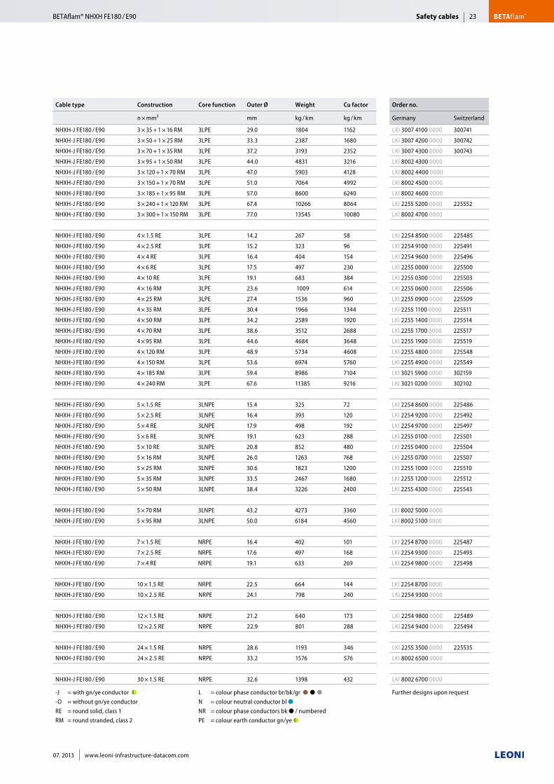
Cable type Construction Core function Outer Ø Weight Cu factor Order no.
n × mm² mm kg / km kg / km Germany Switzerland
NHXH-J FE180 / E90 3 × 35 + 1 × 16 RM 3LPE 29.0 1804 1162 LKI 3007 4100 0000 300741
NHXH-J FE180 / E90 3 × 50 + 1 × 25 RM 3LPE 33.3 2387 1680 LKI 3007 4200 0000 300742
NHXH-J FE180 / E90 3 × 70 + 1 × 35 RM 3LPE 37.2 3193 2352 LKI 3007 4300 0000 300743
NHXH-J FE180 / E90 3 × 95 + 1 × 50 RM 3LPE 44.0 4831 3216 LKI 8002 4300 0000
NHXH-J FE180 / E90 3 × 120 + 1 × 70 RM 3LPE 47.0 5903 4128 LKI 8002 4400 0000
NHXH-J FE180 / E90 3 × 150 + 1 × 70 RM 3LPE 51.0 7064 4992 LKI 8002 4500 0000
NHXH-J FE180 / E90 3 × 185 + 1 × 95 RM 3LPE 57.0 8600 6240 LKI 8002 4600 0000
NHXH-J FE180 / E90 3 × 240 + 1 × 120 RM 3LPE 67.4 10266 8064 LKI 2255 5200 0000 225552
NHXH-J FE180 / E90 3 × 300 + 1 × 150 RM 3LPE 77.0 13545 10080 LKI 8002 4700 0000
NHXH-J FE180 / E90 4 × 1.5 RE 3LPE 14.2 267 58 LKI 2254 8500 0000 225485
NHXH-J FE180 / E90 4 × 2.5 RE 3LPE 15.2 323 96 LKI 2254 9100 0000 225491
NHXH-J FE180 / E90 4 × 4 RE 3LPE 16.4 404 154 LKI 2254 9600 0000 225496
NHXH-J FE180 / E90 4 × 6 RE 3LPE 17.5 497 230 LKI 2255 0000 0000 225500
NHXH-J FE180 / E90 4 × 10 RE 3LPE 19.1 683 384 LKI 2255 0300 0000 225503
NHXH-J FE180 / E90 4 × 16 RM 3LPE 23.6 1009 614 LKI 2255 0600 0000 225506
NHXH-J FE180 / E90 4 × 25 RM 3LPE 27.4 1536 960 LKI 2255 0900 0000 225509
NHXH-J FE180 / E90 4 × 35 RM 3LPE 30.4 1966 1344 LKI 2255 1100 0000 225511
NHXH-J FE180 / E90 4 × 50 RM 3LPE 34.2 2589 1920 LKI 2255 1400 0000 225514
NHXH-J FE180 / E90 4 × 70 RM 3LPE 38.6 3512 2688 LKI 2255 1700 0000 225517
NHXH-J FE180 / E90 4 × 95 RM 3LPE 44.6 4684 3648 LKI 2255 1900 0000 225519
NHXH-J FE180 / E90 4 × 120 RM 3LPE 48.9 5734 4608 LKI 2255 4800 0000 225548
NHXH-J FE180 / E90 4 × 150 RM 3LPE 53.6 6974 5760 LKI 2255 4900 0000 225549
NHXH-J FE180 / E90 4 × 185 RM 3LPE 59.4 8986 7104 LKI 3021 5900 0000 302159
NHXH-J FE180 / E90 4 × 240 RM 3LPE 67.6 11385 9216 LKI 3021 0200 0000 302102
NHXH-J FE180 / E90 5 × 1.5 RE 3LNPE 15.4 325 72 LKI 2254 8600 0000 225486
NHXH-J FE180 / E90 5 × 2.5 RE 3LNPE 16.4 393 120 LKI 2254 9200 0000 225492
NHXH-J FE180 / E90 5 × 4 RE 3LNPE 17.9 498 192 LKI 2254 9700 0000 225497
NHXH-J FE180 / E90 5 × 6 RE 3LNPE 19.1 623 288 LKI 2255 0100 0000 225501
NHXH-J FE180 / E90 5 × 10 RE 3LNPE 20.8 852 480 LKI 2255 0400 0000 225504
NHXH-J FE180 / E90 5 × 16 RM 3LNPE 26.0 1263 768 LKI 2255 0700 0000 225507
NHXH-J FE180 / E90 5 × 25 RM 3LNPE 30.6 1823 1200 LKI 2255 1000 0000 225510
NHXH-J FE180 / E90 5 × 35 RM 3LNPE 33.5 2467 1680 LKI 2255 1200 0000 225512
NHXH-J FE180 / E90 5 × 50 RM 3LNPE 38.4 3226 2400 LKI 2255 4300 0000 225543
NHXH-J FE180 / E90 5 × 70 RM 3LNPE 43.2 4273 3360 LKI 8002 5000 0000
NHXH-J FE180 / E90 5 × 95 RM 3LNPE 50.0 6184 4560 LKI 8002 5100 0000
NHXH-J FE180 / E90 7 × 1.5 RE NRPE 16.4 402 101 LKI 2254 8700 0000 225487
NHXH-J FE180 / E90 7 × 2.5 RE NRPE 17.6 497 168 LKI 2254 9300 0000 225493
NHXH-J FE180 / E90 7 × 4 RE NRPE 19.1 633 269 LKI 2254 9800 0000 225498
NHXH-J FE180 / E90 10 × 1.5 RE NRPE 22.5 664 144 LKI 2254 8700 0000
NHXH-J FE180 / E90 10 × 2.5 RE NRPE 24.1 798 240 LKI 2254 9300 0000
NHXH-J FE180 / E90 12 × 1.5 RE NRPE 21.2 640 173 LKI 2254 9800 0000 225489
NHXH-J FE180 / E90 12 × 2.5 RE NRPE 22.9 801 288 LKI 2254 9400 0000 225494
NHXH-J FE180 / E90 24 × 1.5 RE NRPE 28.6 1193 346 LKI 2255 3500 0000 225535
NHXH-J FE180 / E90 24 × 2.5 RE NRPE 33.2 1576 576 LKI 8002 6500 0000
NHXH-J FE180 / E90 30 × 1.5 RE NRPE 32.6 1398 432 LKI 8002 6700 0000
-J = with gn/ye conductor ●◗ ■■ -O = without gn/ye conductor ■ RE = round solid, class 1 RM = round stranded, class 2
L = colour phase conductor br/bk/gr ●■●■●■■ N = colour neutral conductor bl ●■■ NR = colour phase conductors bk ● / numbered PE = colour earth conductor gn/ye ●◗
Further designs upon request
Safety cables BETAflam®BETAflam® NHXH FE180 / E90 23
07. 2013 www.leoni-infrastructure-datacom.com
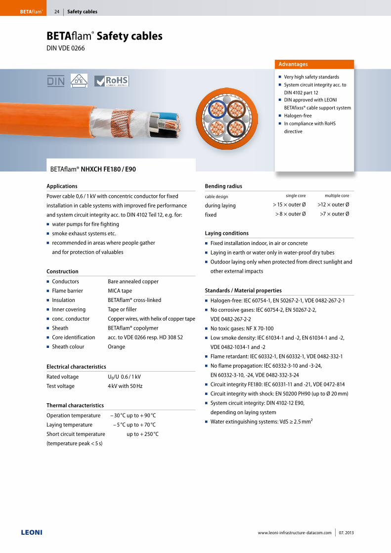
BETAflam® NHXCH FE180 / E90
Applications
Power cable 0,6 / 1 kV with concentric conductor for fixed
installation in cable systems with improved fire performance
and system circuit integrity acc. to DIN 4102 Teil 12, e.g. for:■■ water pumps for fire fighting■■ smoke exhaust systems etc. ■■ recommended in areas where people gather
and for protection of valuables
Construction
■■ Conductors■■ Flame barrier■■ Insulation■■ Inner covering■■ conc. conductor■■ Sheath■■ Core identification■■ Sheath colour
Bare annealed copper
MICA tape
BETAflam® cross-linked
Tape or filler
Copper wires, with helix of copper tape
BETAflam® copolymer
acc. to VDE 0266 resp. HD 308 S2
Orange
Electrical characteristics
Rated voltage
Test voltage
U0/U 0.6 / 1 kV
4 kV with 50 Hz
Thermal characteristics
Operation temperature
Laying temperature
Short circuit temperature
(temperature peak < 5 s)
– 30 °C up to + 90 °C
– 5 °C up to + 70 °C
up to + 250 °C
Bending radius
cable design
during laying
fixed
single core multiple core
> 15 × outer Ø >12 × outer Ø
> 8 × outer Ø >7 × outer Ø
Laying conditions
■■ Fixed installation indoor, in air or concrete■■ Laying in earth or water only in water-proof dry tubes■■ Outdoor laying only when protected from direct sunlight and
other external impacts
Standards / Material properties
■■ Halogen-free: IEC 60754-1, EN 50267-2-1, VDE 0482-267-2-1■■ No corrosive gases: IEC 60754-2, EN 50267-2-2,
VDE 0482-267-2-2■■ No toxic gases: NF X 70-100■■ Low smoke density: IEC 61034-1 and -2, EN 61034-1 and -2,
VDE 0482-1034-1 and -2■■ Flame retardant: IEC 60332-1, EN 60332-1, VDE 0482-332-1■■ No flame propagation: IEC 60332-3-10 and -3-24,
EN 60332-3-10, -24, VDE 0482-332-3-24■■ Circuit integrity FE180: IEC 60331-11 and -21, VDE 0472-814■■ Circuit integrity with shock: EN 50200 PH90 (up to Ø 20 mm)■■ System circuit integrity: DIN 4102-12 E90,
depending on laying system ■■ Water extinguishing systems: VdS ≥ 2.5 mm²
Advantages
■■ Very high safety standards■■ System circuit integrity acc. to
DIN 4102 part 12■■ DIN approved with LEONI
BETAfixss® cable support system■■ Halogen-free■■ In compliance with RoHS
directive
BETAflam® Safety cables DIN VDE 0266
Safety cablesBETAflam® 24
www.leoni-infrastructure-datacom.com 07. 2013
Cable type Construction Core function Outer Ø Weight Cu factor Order no.
n × mm² mm kg / km kg / km Germany Switzerland
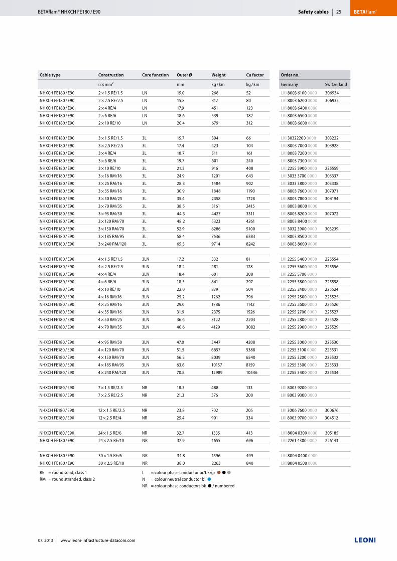
NHXCH FE180 / E90 2 × 1.5 RE/1.5 LN 15.0 268 52 LKI 8003 6100 0000 306934
NHXCH FE180 / E90 2 × 2.5 RE/2.5 LN 15.8 312 80 LKI 8003 6200 0000 306935
NHXCH FE180 / E90 2 × 4 RE/4 LN 17.9 451 123 LKI 8003 6400 0000
NHXCH FE180 / E90 2 × 6 RE/6 LN 18.6 539 182 LKI 8003 6500 0000
NHXCH FE180 / E90 2 × 10 RE/10 LN 20.4 679 312 LKI 8003 6600 0000
NHXCH FE180 / E90 3 × 1.5 RE/1.5 3L 15.7 394 66 LKI 30322200 0000 303222
NHXCH FE180 / E90 3 × 2.5 RE/2.5 3L 17.4 423 104 LKI 8003 7000 0000 303928
NHXCH FE180 / E90 3 × 4 RE/4 3L 18.7 511 161 LKI 8003 7200 0000
NHXCH FE180 / E90 3 × 6 RE/6 3L 19.7 601 240 LKI 8003 7300 0000
NHXCH FE180 / E90 3 × 10 RE/10 3L 21.3 916 408 LKI 2255 5900 0000 225559
NHXCH FE180 / E90 3 × 16 RM/16 3L 24.9 1201 643 LKI 3033 3700 0000 303337
NHXCH FE180 / E90 3 × 25 RM/16 3L 28.3 1484 902 LKI 3033 3800 0000 303338
NHXCH FE180 / E90 3 × 35 RM/16 3L 30.9 1848 1190 LKI 8003 7600 0000 307071
NHXCH FE180 / E90 3 × 50 RM/25 3L 35.4 2358 1728 LKI 8003 7800 0000 304194
NHXCH FE180 / E90 3 × 70 RM/35 3L 38.5 3161 2415 LKI 8003 8000 0000
NHXCH FE180 / E90 3 × 95 RM/50 3L 44.3 4427 3311 LKI 8003 8200 0000 307072
NHXCH FE180 / E90 3 × 120 RM/70 3L 48.2 5323 4261 LKI 8003 8400 0000
NHXCH FE180 / E90 3 × 150 RM/70 3L 52.9 6286 5100 LKI 3032 3900 0000 303239
NHXCH FE180 / E90 3 × 185 RM/95 3L 58.4 7636 6383 LKI 8003 8500 0000
NHXCH FE180 / E90 3 × 240 RM/120 3L 65.3 9714 8242 LKI 8003 8600 0000
NHXCH FE180 / E90 4 × 1.5 RE/1.5 3LN 17.2 332 81 LKI 2255 5400 0000 225554
NHXCH FE180 / E90 4 × 2.5 RE/2.5 3LN 18.2 481 128 LKI 2255 5600 0000 225556
NHXCH FE180 / E90 4 × 4 RE/4 3LN 18.4 601 200 LKI 2255 5700 0000
NHXCH FE180 / E90 4 × 6 RE/6 3LN 18.5 841 297 LKI 2255 5800 0000 225558
NHXCH FE180 / E90 4 × 10 RE/10 3LN 22.0 879 504 LKI 2255 2400 0000 225524
NHXCH FE180 / E90 4 × 16 RM/16 3LN 25.2 1262 796 LKI 2255 2500 0000 225525
NHXCH FE180 / E90 4 × 25 RM/16 3LN 29.0 1786 1142 LKI 2255 2600 0000 225526
NHXCH FE180 / E90 4 × 35 RM/16 3LN 31.9 2375 1526 LKI 2255 2700 0000 225527
NHXCH FE180 / E90 4 × 50 RM/25 3LN 36.6 3122 2203 LKI 2255 2800 0000 225528
NHXCH FE180 / E90 4 × 70 RM/35 3LN 40.6 4129 3082 LKI 2255 2900 0000 225529
NHXCH FE180 / E90 4 × 95 RM/50 3LN 47.0 5447 4208 LKI 2255 3000 0000 225530
NHXCH FE180 / E90 4 × 120 RM/70 3LN 51.5 6657 5388 LKI 2255 3100 0000 225531
NHXCH FE180 / E90 4 × 150 RM/70 3LN 56.5 8039 6540 LKI 2255 3200 0000 225532
NHXCH FE180 / E90 4 × 185 RM/95 3LN 63.6 10157 8159 LKI 2255 3300 0000 225533
NHXCH FE180 / E90 4 × 240 RM/120 3LN 70.8 12989 10546 LKI 2255 3400 0000 225534
NHXCH FE180 / E90 7 × 1.5 RE/2.5 NR 18.3 488 133 LKI 8003 9200 0000
NHXCH FE180 / E90 7 × 2.5 RE/2.5 NR 21.3 576 200 LKI 8003 9300 0000
NHXCH FE180 / E90 12 × 1.5 RE/2.5 NR 23.8 702 205 LKI 3006 7600 0000 300676
NHXCH FE180 / E90 12 × 2.5 RE/4 NR 25.4 901 334 LKI 8003 9700 0000 304512
NHXCH FE180 / E90 24 × 1.5 RE/6 NR 32.7 1335 413 LKI 8004 0300 0000 305185
NHXCH FE180 / E90 24 × 2.5 RE/10 NR 32.9 1655 696 LKI 2261 4300 0000 226143
NHXCH FE180 / E90 30 × 1.5 RE/6 NR 34.8 1596 499 LKI 8004 0400 0000
NHXCH FE180 / E90 30 × 2.5 RE/10 NR 38.0 2263 840 LKI 8004 0500 0000
RE = round solid, class 1 RM = round stranded, class 2
L = colour phase conductor br/bk/gr ●■●■●■■ N = colour neutral conductor bl ●■■ NR = colour phase conductors bk ● / numbered
Safety cables BETAflam®BETAflam® NHXCH FE180 / E90 25
07. 2013 www.leoni-infrastructure-datacom.com
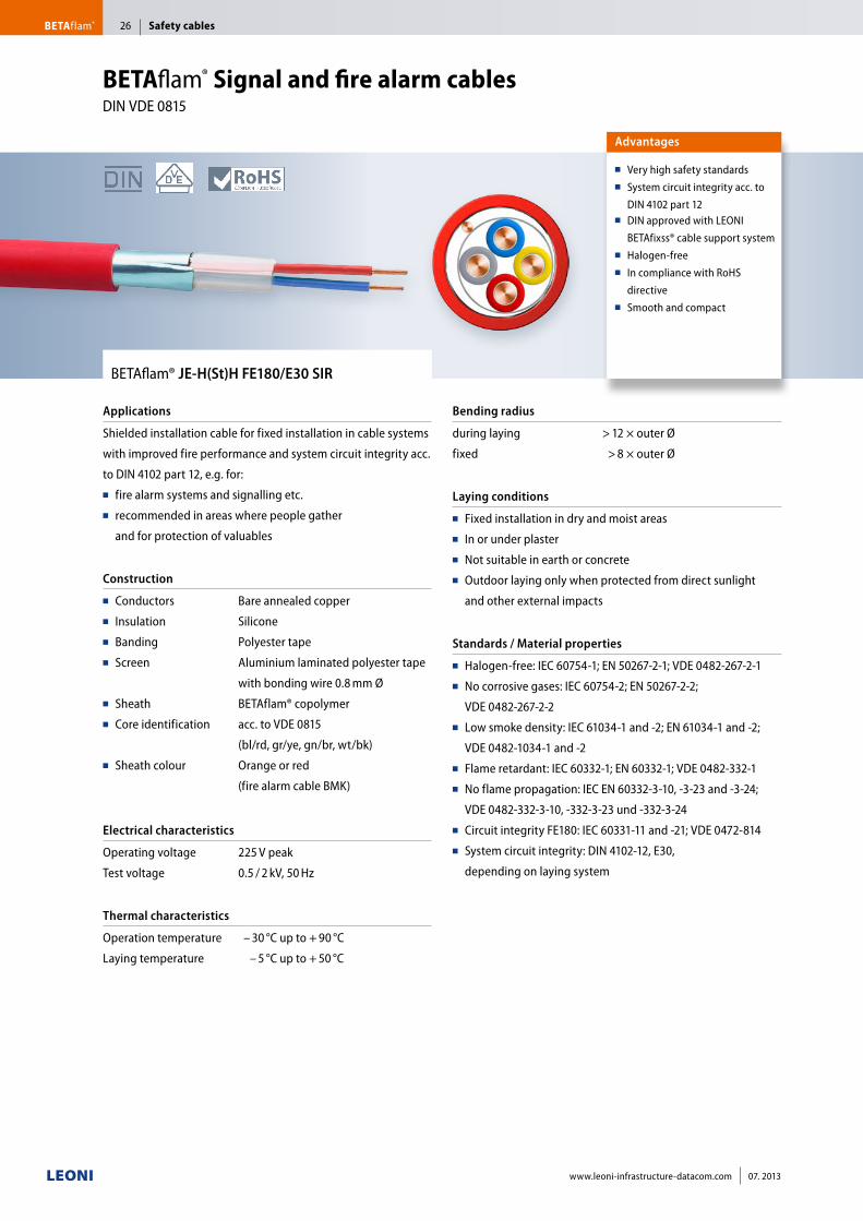
BETAflam® JE-H(St)H FE180/E30 SIR
Applications
Shielded installation cable for fixed installation in cable systems
with improved fire performance and system circuit integrity acc.
to DIN 4102 part 12, e.g. for:■■ fire alarm systems and signalling etc. ■■ recommended in areas where people gather
and for protection of valuables
Construction
■■ Conductors■■ Insulation■■ Banding■■ Screen
■■ Sheath■■ Core identification
■■ Sheath colour
Bare annealed copper
Silicone
Polyester tape
Aluminium laminated polyester tape
with bonding wire 0.8 mm Ø
BETAflam® copolymer
acc. to VDE 0815
(bl/rd, gr/ye, gn/br, wt/bk)
Orange or red
(fire alarm cable BMK)
Electrical characteristics
Operating voltage
Test voltage
225 V peak
0.5 / 2 kV, 50 Hz
Thermal characteristics
Operation temperature
Laying temperature
– 30 °C up to + 90 °C
– 5 °C up to + 50 °C
Bending radius
during laying
fixed
> 12 × outer Ø
> 8 × outer Ø
Laying conditions
■■ Fixed installation in dry and moist areas■■ In or under plaster■■ Not suitable in earth or concrete■■ Outdoor laying only when protected from direct sunlight
and other external impacts
Standards / Material properties
■■ Halogen-free: IEC 60754-1; EN 50267-2-1; VDE 0482-267-2-1■■ No corrosive gases: IEC 60754-2; EN 50267-2-2;
VDE 0482-267-2-2■■ Low smoke density: IEC 61034-1 and -2; EN 61034-1 and -2;
VDE 0482-1034-1 and -2■■ Flame retardant: IEC 60332-1; EN 60332-1; VDE 0482-332-1■■ No flame propagation: IEC EN 60332-3-10, -3-23 and -3-24;
VDE 0482-332-3-10, -332-3-23 und -332-3-24 ■■ Circuit integrity FE180: IEC 60331-11 and -21; VDE 0472-814■■ System circuit integrity: DIN 4102-12, E30,
depending on laying system
Advantages
■■ Very high safety standards■■ System circuit integrity acc. to
DIN 4102 part 12■■ DIN approved with LEONI
BETAfixss® cable support system■■ Halogen-free ■■ In compliance with RoHS
directive■■ Smooth and compact
BETAflam® Signal and fire alarm cables DIN VDE 0815
Safety cablesBETAflam® 26
www.leoni-infrastructure-datacom.com 07. 2013
Cable type Sheath colour Construction Outer Ø Weight Cu factor Order no.
n × 2 × mm mm kg / km kg / km Germany Switzerland
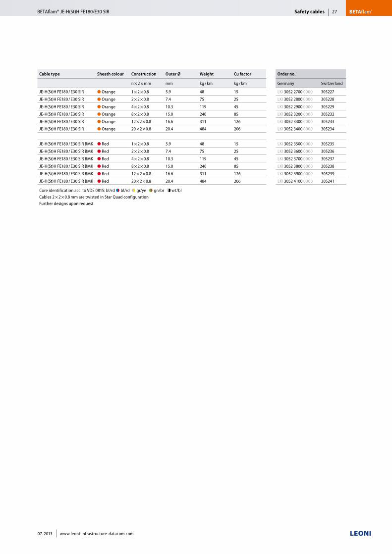
JE-H(St)H FE180 / E30 SIR ● Orange 1 × 2 × 0.8 5.9 48 15 LKI 3052 2700 0000 305227
JE-H(St)H FE180 / E30 SIR ● Orange 2 × 2 × 0.8 7.4 75 25 LKI 3052 2800 0000 305228
JE-H(St)H FE180 / E30 SIR ● Orange 4 × 2 × 0.8 10.3 119 45 LKI 3052 2900 0000 305229
JE-H(St)H FE180 / E30 SIR ● Orange 8 × 2 × 0.8 15.0 240 85 LKI 3052 3200 0000 305232
JE-H(St)H FE180 / E30 SIR ● Orange 12 × 2 × 0.8 16.6 311 126 LKI 3052 3300 0000 305233
JE-H(St)H FE180 / E30 SIR ● Orange 20 × 2 × 0.8 20.4 484 206 LKI 3052 3400 0000 305234
JE-H(St)H FE180 / E30 SIR BMK ● Red 1 × 2 × 0.8 5.9 48 15 LKI 3052 3500 0000 305235
JE-H(St)H FE180 / E30 SIR BMK ● Red 2 × 2 × 0.8 7.4 75 25 LKI 3052 3600 0000 305236
JE-H(St)H FE180 / E30 SIR BMK ● Red 4 × 2 × 0.8 10.3 119 45 LKI 3052 3700 0000 305237
JE-H(St)H FE180 / E30 SIR BMK ● Red 8 × 2 × 0.8 15.0 240 85 LKI 3052 3800 0000 305238
JE-H(St)H FE180 / E30 SIR BMK ● Red 12 × 2 × 0.8 16.6 311 126 LKI 3052 3900 0000 305239
JE-H(St)H FE180 / E30 SIR BMK ● Red 20 × 2 × 0.8 20.4 484 206 LKI 3052 4100 0000 305241
Core identification acc. to VDE 0815: bl/rd ●◗■bl/rd ●◗■gr/ye ●◗■gn/br ●◗ wt/bl Cables 2 × 2 × 0.8 mm are twisted in Star Quad configurationFurther designs upon request
Safety cables BETAflam®BETAflam® JE-H(St)H FE180/E30 SIR 27
07. 2013 www.leoni-infrastructure-datacom.com
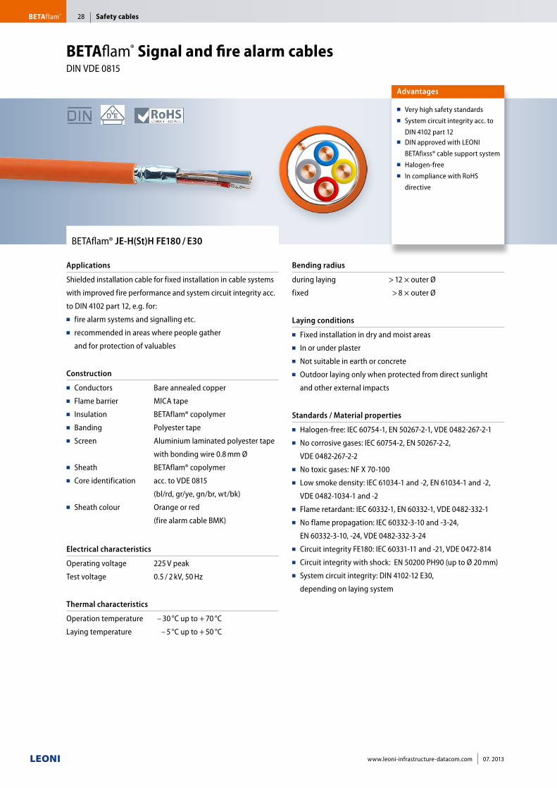
BETAflam® JE-H(St)H FE180 / E30
Applications
Shielded installation cable for fixed installation in cable systems
with improved fire performance and system circuit integrity acc.
to DIN 4102 part 12, e.g. for:■■ fire alarm systems and signalling etc. ■■ recommended in areas where people gather
and for protection of valuables
Construction
■■ Conductors■■ Flame barrier■■ Insulation■■ Banding■■ Screen
■■ Sheath■■ Core identification
■■ Sheath colour
Bare annealed copper
MICA tape
BETAflam® copolymer
Polyester tape
Aluminium laminated polyester tape
with bonding wire 0.8 mm Ø
BETAflam® copolymer
acc. to VDE 0815
(bl/rd, gr/ye, gn/br, wt/bk)
Orange or red
(fire alarm cable BMK)
Electrical characteristics
Operating voltage
Test voltage
225 V peak
0.5 / 2 kV, 50 Hz
Thermal characteristics
Operation temperature
Laying temperature
– 30 °C up to + 70 °C
– 5 °C up to + 50 °C
Bending radius
during laying
fixed
> 12 × outer Ø
> 8 × outer Ø
Laying conditions
■■ Fixed installation in dry and moist areas■■ In or under plaster■■ Not suitable in earth or concrete■■ Outdoor laying only when protected from direct sunlight
and other external impacts
Standards / Material properties
■■ Halogen-free: IEC 60754-1, EN 50267-2-1, VDE 0482-267-2-1■■ No corrosive gases: IEC 60754-2, EN 50267-2-2,
VDE 0482-267-2-2■■ No toxic gases: NF X 70-100■■ Low smoke density: IEC 61034-1 and -2, EN 61034-1 and -2,
VDE 0482-1034-1 and -2■■ Flame retardant: IEC 60332-1, EN 60332-1, VDE 0482-332-1■■ No flame propagation: IEC 60332-3-10 and -3-24,
EN 60332-3-10, -24, VDE 0482-332-3-24■■ Circuit integrity FE180: IEC 60331-11 and -21, VDE 0472-814■■ Circuit integrity with shock: EN 50200 PH90 (up to Ø 20 mm)■■ System circuit integrity: DIN 4102-12 E30,
depending on laying system
Advantages
■■ Very high safety standards■■ System circuit integrity acc. to
DIN 4102 part 12■■ DIN approved with LEONI
BETAfixss® cable support system■■ Halogen-free■■ In compliance with RoHS
directive
BETAflam® Signal and fire alarm cables DIN VDE 0815
Safety cablesBETAflam® 28
www.leoni-infrastructure-datacom.com 07. 2013
Cable type Sheath colour Construction Outer Ø Weight Cu factor Order no.
n × 2 × mm mm kg / km kg / km Germany Switzerland
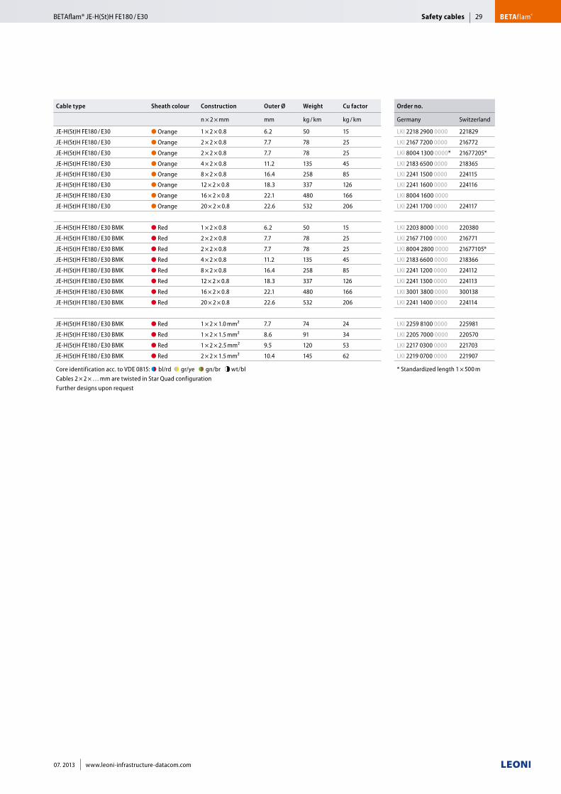
JE-H(St)H FE180 / E30 ● Orange 1 × 2 × 0.8 6.2 50 15 LKI 2218 2900 0000 221829
JE-H(St)H FE180 / E30 ● Orange 2 × 2 × 0.8 7.7 78 25 LKI 2167 7200 0000 216772
JE-H(St)H FE180 / E30 ● Orange 2 × 2 × 0.8 7.7 78 25 LKI 8004 1300 0000* 21677205*
JE-H(St)H FE180 / E30 ● Orange 4 × 2 × 0.8 11.2 135 45 LKI 2183 6500 0000 218365
JE-H(St)H FE180 / E30 ● Orange 8 × 2 × 0.8 16.4 258 85 LKI 2241 1500 0000 224115
JE-H(St)H FE180 / E30 ● Orange 12 × 2 × 0.8 18.3 337 126 LKI 2241 1600 0000 224116
JE-H(St)H FE180 / E30 ● Orange 16 × 2 × 0.8 22.1 480 166 LKI 8004 1600 0000
JE-H(St)H FE180 / E30 ● Orange 20 × 2 × 0.8 22.6 532 206 LKI 2241 1700 0000 224117
JE-H(St)H FE180 / E30 BMK ● Red 1 × 2 × 0.8 6.2 50 15 LKI 2203 8000 0000 220380
JE-H(St)H FE180 / E30 BMK ● Red 2 × 2 × 0.8 7.7 78 25 LKI 2167 7100 0000 216771
JE-H(St)H FE180 / E30 BMK ● Red 2 × 2 × 0.8 7.7 78 25 LKI 8004 2800 0000 21677105*
JE-H(St)H FE180 / E30 BMK ● Red 4 × 2 × 0.8 11.2 135 45 LKI 2183 6600 0000 218366
JE-H(St)H FE180 / E30 BMK ● Red 8 × 2 × 0.8 16.4 258 85 LKI 2241 1200 0000 224112
JE-H(St)H FE180 / E30 BMK ● Red 12 × 2 × 0.8 18.3 337 126 LKI 2241 1300 0000 224113
JE-H(St)H FE180 / E30 BMK ● Red 16 × 2 × 0.8 22.1 480 166 LKI 3001 3800 0000 300138
JE-H(St)H FE180 / E30 BMK ● Red 20 × 2 × 0.8 22.6 532 206 LKI 2241 1400 0000 224114
JE-H(St)H FE180 / E30 BMK ● Red 1 × 2 × 1.0 mm² 7.7 74 24 LKI 2259 8100 0000 225981
JE-H(St)H FE180 / E30 BMK ● Red 1 × 2 × 1.5 mm² 8.6 91 34 LKI 2205 7000 0000 220570
JE-H(St)H FE180 / E30 BMK ● Red 1 × 2 × 2.5 mm² 9.5 120 53 LKI 2217 0300 0000 221703
JE-H(St)H FE180 / E30 BMK ● Red 2 × 2 × 1.5 mm² 10.4 145 62 LKI 2219 0700 0000 221907
Core identification acc. to VDE 0815: ●◗■bl/rd ●◗■gr/ye ●◗■gn/br ●◗ wt/bl Cables 2 × 2 × … mm are twisted in Star Quad configurationFurther designs upon request
* Standardized length 1 × 500 m
Safety cables BETAflam®BETAflam® JE-H(St)H FE180 / E30 29
07. 2013 www.leoni-infrastructure-datacom.com
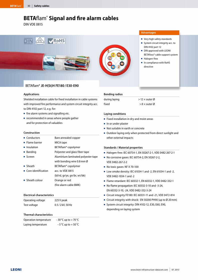
BETAflam® JE-H(St)H FE180 / E30-E90
Applications
Shielded installation cable for fixed installation in cable systems
with improved fire performance and system circuit integrity acc.
to DIN 4102 part 12, e.g. for:■■ fire alarm systems and signalling etc. ■■ recommended in areas where people gather
and for protection of valuables
Construction
■■ Conductors■■ Flame barrier■■ Insulation■■ Banding■■ Screen
■■ Sheath■■ Core identification
■■ Sheath colour
Bare annealed copper
MICA tape
BETAflam® copolymer
Polyester and glass fiber tape
Aluminium laminated polyester tape
with bonding wire 0.8 mm Ø
BETAflam® copolymer
acc. to VDE 0815
(bl/rd, gr/ye, gn/br, wt/bk)
Orange or red
(fire alarm cable BMK)
Electrical characteristics
Operating voltage
Test voltage
225 V peak
0.5 / 2 kV, 50 Hz
Thermal characteristics
Operation temperature
Laying temperature
– 30 °C up to + 70 °C
– 5 °C up to + 50 °C
Bending radius
during laying
fixed
> 12 × outer Ø
> 8 × outer Ø
Laying conditions
■■ Fixed installation in dry and moist areas■■ In or under plaster■■ Not suitable in earth or concrete■■ Outdoor laying only when protected from direct sunlight and
other external impacts
Standards / Material properties
■■ Halogen-free: IEC 60754-1, EN 50267-2-1, VDE 0482-267-2-1■■ No corrosive gases: IEC 60754-2, EN 50267-2-2,
VDE 0482-267-2-2■■ No toxic gases: NF X 70-100■■ Low smoke density: IEC 61034-1 and -2, EN 61034-1 and -2,
VDE 0482-1034-1 and -2■■ Flame retardant: IEC 60332-1, EN 60332-1, VDE 0482-332-1■■ No flame propagation: IEC 60332-3-10 and -3-24,
EN 60332-3-10, -24, VDE 0482-332-3-24■■ Circuit integrity FE180: IEC 60331-11 and -21, VDE 0472-814■■ Circuit integrity with shock: EN 50200 PH90 (up to Ø 20 mm)■■ System circuit integrity: DIN 4102-12, E30, E60, E90,
depending on laying system
Advantages
■■ Very high safety standards■■ System circuit integrity acc. to
DIN 4102 part 12■■ DIN approved with LEONI
BETAfixss® cable support system■■ Halogen-free■■ In compliance with RoHS
directive
BETAflam® Signal and fire alarm cables DIN VDE 0815
Safety cablesBETAflam® 30
www.leoni-infrastructure-datacom.com 07. 2013
Cable type Sheath colour Construction Outer Ø Weight Cu factor Order no.
n × 2 × mm mm kg / km kg / km Germany Switzerland
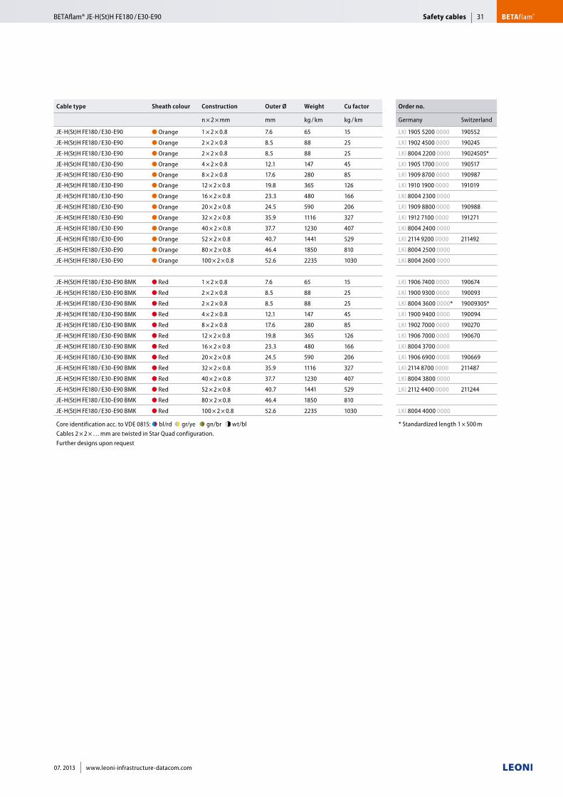
JE-H(St)H FE180 / E30-E90 ● Orange 1 × 2 × 0.8 7.6 65 15 LKI 1905 5200 0000 190552
JE-H(St)H FE180 / E30-E90 ● Orange 2 × 2 × 0.8 8.5 88 25 LKI 1902 4500 0000 190245
JE-H(St)H FE180 / E30-E90 ● Orange 2 × 2 × 0.8 8.5 88 25 LKI 8004 2200 0000 19024505*
JE-H(St)H FE180 / E30-E90 ● Orange 4 × 2 × 0.8 12.1 147 45 LKI 1905 1700 0000 190517
JE-H(St)H FE180 / E30-E90 ● Orange 8 × 2 × 0.8 17.6 280 85 LKI 1909 8700 0000 190987
JE-H(St)H FE180 / E30-E90 ● Orange 12 × 2 × 0.8 19.8 365 126 LKI 1910 1900 0000 191019
JE-H(St)H FE180 / E30-E90 ● Orange 16 × 2 × 0.8 23.3 480 166 LKI 8004 2300 0000
JE-H(St)H FE180 / E30-E90 ● Orange 20 × 2 × 0.8 24.5 590 206 LKI 1909 8800 0000 190988
JE-H(St)H FE180 / E30-E90 ● Orange 32 × 2 × 0.8 35.9 1116 327 LKI 1912 7100 0000 191271
JE-H(St)H FE180 / E30-E90 ● Orange 40 × 2 × 0.8 37.7 1230 407 LKI 8004 2400 0000
JE-H(St)H FE180 / E30-E90 ● Orange 52 × 2 × 0.8 40.7 1441 529 LKI 2114 9200 0000 211492
JE-H(St)H FE180 / E30-E90 ● Orange 80 × 2 × 0.8 46.4 1850 810 LKI 8004 2500 0000
JE-H(St)H FE180 / E30-E90 ● Orange 100 × 2 × 0.8 52.6 2235 1030 LKI 8004 2600 0000
JE-H(St)H FE180 / E30-E90 BMK ● Red 1 × 2 × 0.8 7.6 65 15 LKI 1906 7400 0000 190674
JE-H(St)H FE180 / E30-E90 BMK ● Red 2 × 2 × 0.8 8.5 88 25 LKI 1900 9300 0000 190093
JE-H(St)H FE180 / E30-E90 BMK ● Red 2 × 2 × 0.8 8.5 88 25 LKI 8004 3600 0000* 19009305*
JE-H(St)H FE180 / E30-E90 BMK ● Red 4 × 2 × 0.8 12.1 147 45 LKI 1900 9400 0000 190094
JE-H(St)H FE180 / E30-E90 BMK ● Red 8 × 2 × 0.8 17.6 280 85 LKI 1902 7000 0000 190270
JE-H(St)H FE180 / E30-E90 BMK ● Red 12 × 2 × 0.8 19.8 365 126 LKI 1906 7000 0000 190670
JE-H(St)H FE180 / E30-E90 BMK ● Red 16 × 2 × 0.8 23.3 480 166 LKI 8004 3700 0000
JE-H(St)H FE180 / E30-E90 BMK ● Red 20 × 2 × 0.8 24.5 590 206 LKI 1906 6900 0000 190669
JE-H(St)H FE180 / E30-E90 BMK ● Red 32 × 2 × 0.8 35.9 1116 327 LKI 2114 8700 0000 211487
JE-H(St)H FE180 / E30-E90 BMK ● Red 40 × 2 × 0.8 37.7 1230 407 LKI 8004 3800 0000
JE-H(St)H FE180 / E30-E90 BMK ● Red 52 × 2 × 0.8 40.7 1441 529 LKI 2112 4400 0000 211244
JE-H(St)H FE180 / E30-E90 BMK ● Red 80 × 2 × 0.8 46.4 1850 810
JE-H(St)H FE180 / E30-E90 BMK ● Red 100 × 2 × 0.8 52.6 2235 1030 LKI 8004 4000 0000
Core identification acc. to VDE 0815: ●◗■bl/rd ●◗■gr/ye ●◗■gn/br ●◗ wt/bl Cables 2 × 2 × … mm are twisted in Star Quad configuration.Further designs upon request
* Standardized length 1 × 500 m
Safety cables BETAflam®BETAflam® JE-H(St)H FE180 / E30-E90 31
07. 2013 www.leoni-infrastructure-datacom.com
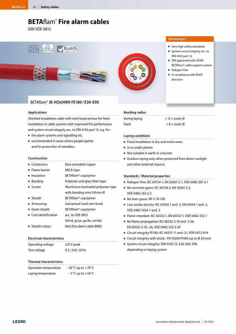
BETAflam® JE-H(St)HRH FE180 / E30-E90
Applications
Shielded installation cable with steel braid armour for fixed
installation in cable systems with improved fire performance
and system circuit integrity acc. to DIN 4102 part 12, e.g. for:■■ fire alarm systems and signalling etc. ■■ recommended in areas where people gather
and for protection of valuables
Construction
■■ Conductors■■ Flame barrier■■ Insulation■■ Banding■■ Screen
■■ Sheath■■ Armouring■■ Outer sheath■■ Core identification
■■ Sheath colour
Bare annealed copper
MICA tape
BETAflam® copolymer
Polyester and glass fiber tape
Aluminium laminated polyester tape
with bonding wire 0.8 mm Ø
BETAflam® copolymer
Galvanised steel wire braid
BETAflam® copolymer
acc. to VDE 0815
(bl/rd, gr/ye, gn/br, wt/bk)
Red (fire alarm cable BMK)
Electrical characteristics
Operating voltage
Test voltage
225 V peak
0.5 / 2 kV, 50 Hz
Thermal characteristics
Operation temperature
Laying temperature
– 30 °C up to + 70 °C
– 5 °C up to + 50 °C
Bending radius
during laying
fixed
> 12 × outer Ø
> 8 × outer Ø
Laying conditions
■■ Fixed installation in dry and moist areas■■ In or under plaster■■ Not suitable in earth or concrete■■ Outdoor laying only when protected from direct sunlight
and other external impacts
Standards / Material properties
■■ Halogen-free: IEC 60754-1, EN 50267-2-1, VDE 0482-267-2-1■■ No corrosive gases: IEC 60754-2, EN 50267-2-2,
VDE 0482-267-2-2■■ No toxic gases: NF X 70-100■■ Low smoke density: IEC 61034-1 and -2, EN 61034-1 and -2,
VDE 0482-1034-1 and -2■■ Flame retardant: IEC 60332-1, EN 60332-1, VDE 0482-332-1■■ No flame propagation: IEC 60332-3-10 and -3-24,
EN 60332-3-10, -24, VDE 0482-332-3-24■■ Circuit integrity FE180: IEC 60331-11 and -21, VDE 0472-814■■ Circuit integrity with shock: EN 50200 PH90 (up to Ø 20 mm)■■ System circuit integrity: DIN 4102-12, E30, E60, E90,
depending on laying system
Advantages
■■ Very high safety standards■■ System circuit integrity acc. to
DIN 4102 part 12■■ DIN approved with LEONI
BETAfixss® cable support system■■ Halogen-free■■ In compliance with RoHS
directive
BETAflam® Fire alarm cablesDIN VDE 0815
Safety cablesBETAflam® 32
www.leoni-infrastructure-datacom.com 07. 2013
Cable type Sheath colour Construction Outer Ø Weight Cu factor Order no.
n × 2 × mm mm kg / km kg / km Germany Switzerland
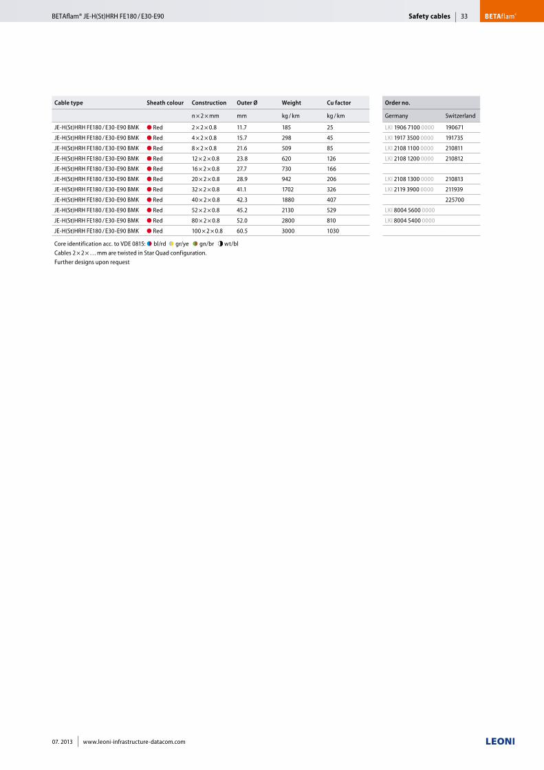
JE-H(St)HRH FE180 / E30-E90 BMK ● Red 2 × 2 × 0.8 11.7 185 25 LKI 1906 7100 0000 190671
JE-H(St)HRH FE180 / E30-E90 BMK ● Red 4 × 2 × 0.8 15.7 298 45 LKI 1917 3500 0000 191735
JE-H(St)HRH FE180 / E30-E90 BMK ● Red 8 × 2 × 0.8 21.6 509 85 LKI 2108 1100 0000 210811
JE-H(St)HRH FE180 / E30-E90 BMK ● Red 12 × 2 × 0.8 23.8 620 126 LKI 2108 1200 0000 210812
JE-H(St)HRH FE180 / E30-E90 BMK ● Red 16 × 2 × 0.8 27.7 730 166
JE-H(St)HRH FE180 / E30-E90 BMK ● Red 20 × 2 × 0.8 28.9 942 206 LKI 2108 1300 0000 210813
JE-H(St)HRH FE180 / E30-E90 BMK ● Red 32 × 2 × 0.8 41.1 1702 326 LKI 2119 3900 0000 211939
JE-H(St)HRH FE180 / E30-E90 BMK ● Red 40 × 2 × 0.8 42.3 1880 407 225700
JE-H(St)HRH FE180 / E30-E90 BMK ● Red 52 × 2 × 0.8 45.2 2130 529 LKI 8004 5600 0000
JE-H(St)HRH FE180 / E30-E90 BMK ● Red 80 × 2 × 0.8 52.0 2800 810 LKI 8004 5400 0000
JE-H(St)HRH FE180 / E30-E90 BMK ● Red 100 × 2 × 0.8 60.5 3000 1030
Core identification acc. to VDE 0815: ●◗■bl/rd ●◗■gr/ye ●◗■gn/br ●◗ wt/bl Cables 2 × 2 × … mm are twisted in Star Quad configuration.Further designs upon request
Safety cables BETAflam®BETAflam® JE-H(St)HRH FE180 / E30-E90 33
07. 2013 www.leoni-infrastructure-datacom.com
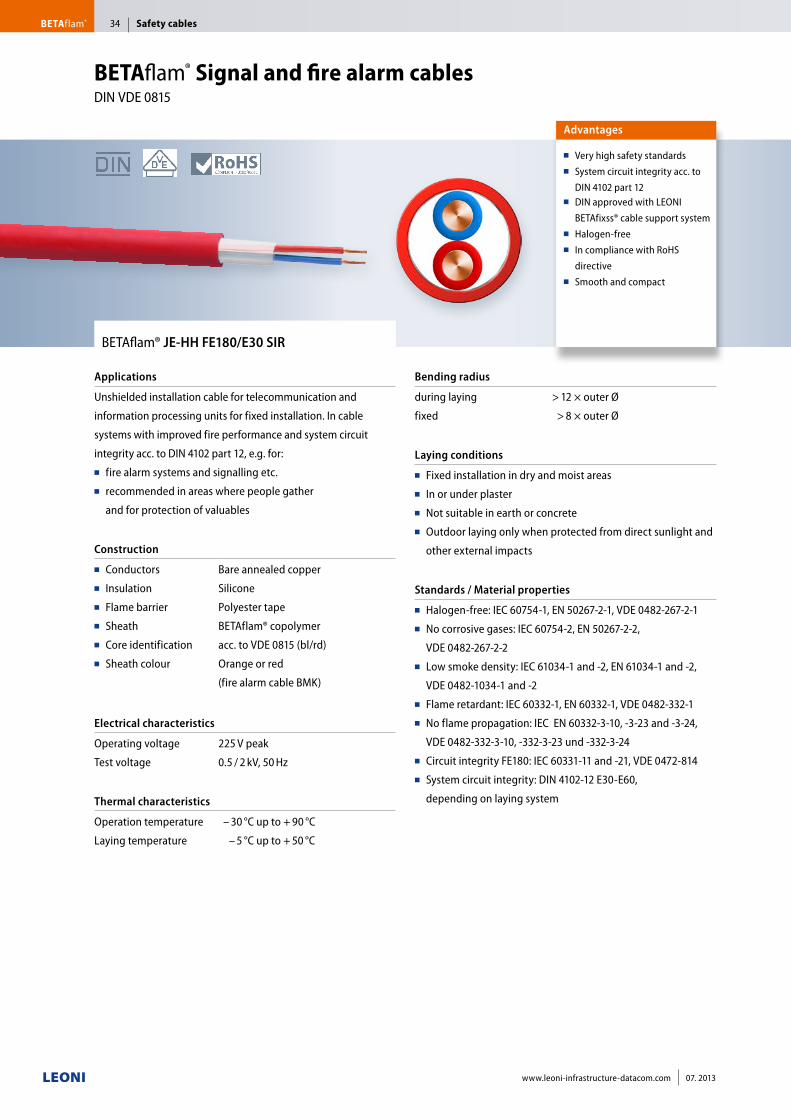
BETAflam® JE-HH FE180/E30 SIR
Applications
Unshielded installation cable for telecommunication and
information processing units for fixed installation. In cable
systems with improved fire performance and system circuit
integrity acc. to DIN 4102 part 12, e.g. for:■■ fire alarm systems and signalling etc. ■■ recommended in areas where people gather
and for protection of valuables
Construction
■■ Conductors■■ Insulation■■ Flame barrier■■ Sheath■■ Core identification■■ Sheath colour
Bare annealed copper
Silicone
Polyester tape
BETAflam® copolymer
acc. to VDE 0815 (bl/rd)
Orange or red
(fire alarm cable BMK)
Electrical characteristics
Operating voltage
Test voltage
225 V peak
0.5 / 2 kV, 50 Hz
Thermal characteristics
Operation temperature
Laying temperature
– 30 °C up to + 90 °C
– 5 °C up to + 50 °C
Bending radius
during laying
fixed
> 12 × outer Ø
> 8 × outer Ø
Laying conditions
■■ Fixed installation in dry and moist areas■■ In or under plaster■■ Not suitable in earth or concrete■■ Outdoor laying only when protected from direct sunlight and
other external impacts
Standards / Material properties
■■ Halogen-free: IEC 60754-1, EN 50267-2-1, VDE 0482-267-2-1■■ No corrosive gases: IEC 60754-2, EN 50267-2-2,
VDE 0482-267-2-2■■ Low smoke density: IEC 61034-1 and -2, EN 61034-1 and -2,
VDE 0482-1034-1 and -2■■ Flame retardant: IEC 60332-1, EN 60332-1, VDE 0482-332-1■■ No flame propagation: IEC EN 60332-3-10, -3-23 and -3-24,
VDE 0482-332-3-10, -332-3-23 und -332-3-24 ■■ Circuit integrity FE180: IEC 60331-11 and -21, VDE 0472-814■■ System circuit integrity: DIN 4102-12 E30-E60,
depending on laying system
Advantages
■■ Very high safety standards■■ System circuit integrity acc. to
DIN 4102 part 12■■ DIN approved with LEONI
BETAfixss® cable support system■■ Halogen-free ■■ In compliance with RoHS
directive■■ Smooth and compact
BETAflam® Signal and fire alarm cables DIN VDE 0815
Safety cablesBETAflam® 34
www.leoni-infrastructure-datacom.com 07. 2013
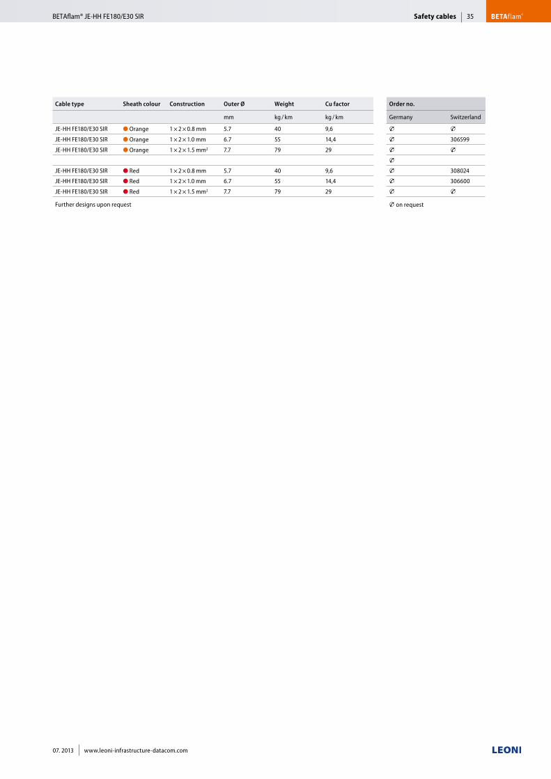
Cable type Sheath colour Construction Outer Ø Weight Cu factor Order no.
mm kg / km kg / km Germany Switzerland
JE-HH FE180/E30 SIR ● Orange 1 × 2 × 0.8 mm 5.7 40 9,6 T TJE-HH FE180/E30 SIR ● Orange 1 × 2 × 1.0 mm 6.7 55 14,4 T 306599
JE-HH FE180/E30 SIR ● Orange 1 × 2 × 1.5 mm2 7.7 79 29 T T
TJE-HH FE180/E30 SIR ● Red 1 × 2 × 0.8 mm 5.7 40 9,6 T 308024
JE-HH FE180/E30 SIR ● Red 1 × 2 × 1.0 mm 6.7 55 14,4 T 306600
JE-HH FE180/E30 SIR ● Red 1 × 2 × 1.5 mm2 7.7 79 29 T T
Further designs upon request T on request
Safety cables BETAflam®BETAflam® JE-HH FE180/E30 SIR 35
07. 2013 www.leoni-infrastructure-datacom.com
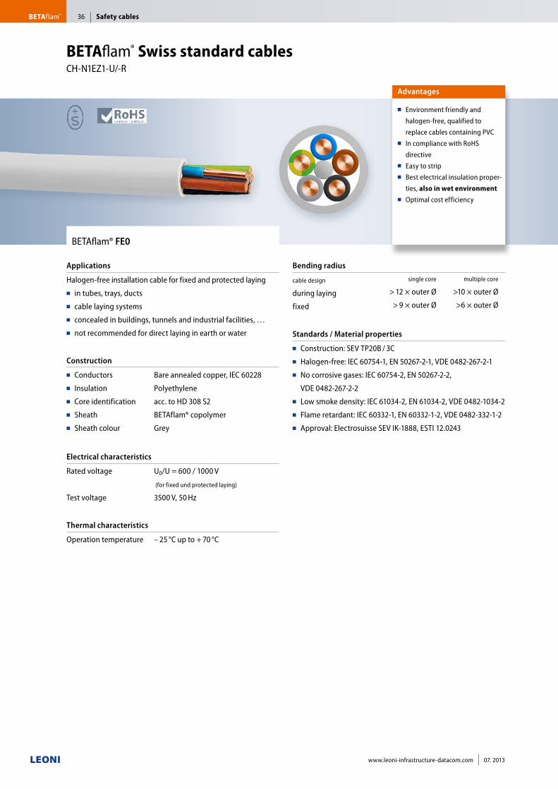
BETAflam® FE0
Applications
Halogen-free installation cable for fixed and protected laying■■ in tubes, trays, ducts■■ cable laying systems■■ concealed in buildings, tunnels and industrial facilities, … ■■ not recommended for direct laying in earth or water
Construction
■■ Conductors■■ Insulation■■ Core identification■■ Sheath■■ Sheath colour
Bare annealed copper, IEC 60228
Polyethylene
acc. to HD 308 S2
BETAflam® copolymer
Grey
Electrical characteristics
Rated voltage
Test voltage
U0/U = 600 / 1000 V
(for fixed und protected laying)
3500 V, 50 Hz
Thermal characteristics
Operation temperature – 25 °C up to + 70 °C
Bending radius
cable design
during laying
fixed
single core multiple core
> 12 × outer Ø >10 × outer Ø
> 9 × outer Ø >6 × outer Ø
Standards / Material properties
■■ Construction: SEV TP20B / 3C■■ Halogen-free: IEC 60754-1, EN 50267-2-1, VDE 0482-267-2-1■■ No corrosive gases: IEC 60754-2, EN 50267-2-2,
VDE 0482-267-2-2 ■■ Low smoke density: IEC 61034-2, EN 61034-2, VDE 0482-1034-2■■ Flame retardant: IEC 60332-1, EN 60332-1-2, VDE 0482-332-1-2■■ Approval: Electrosuisse SEV IK-1888, ESTI 12.0243
Advantages
■■ Environment friendly and
halogen-free, qualified to
replace cables containing PVC■■ In compliance with RoHS
directive■■ Easy to strip■■ Best electrical insulation proper-
ties, also in wet environment■■ Optimal cost efficiency
BETAflam® Swiss standard cables CH-N1EZ1-U/-R
Safety cablesBETAflam® 36
www.leoni-infrastructure-datacom.com 07. 2013
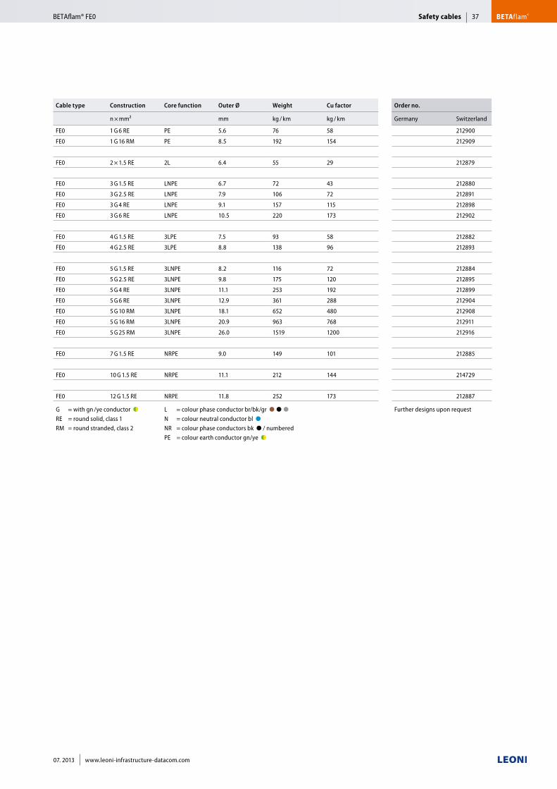
Cable type Construction Core function Outer Ø Weight Cu factor Order no.
n × mm² mm kg / km kg / km Germany Switzerland
FE0 1 G 6 RE PE 5.6 76 58 212900
FE0 1 G 16 RM PE 8.5 192 154 212909
FE0 2 × 1.5 RE 2L 6.4 55 29 212879
FE0 3 G 1.5 RE LNPE 6.7 72 43 212880
FE0 3 G 2.5 RE LNPE 7.9 106 72 212891
FE0 3 G 4 RE LNPE 9.1 157 115 212898
FE0 3 G 6 RE LNPE 10.5 220 173 212902
FE0 4 G 1.5 RE 3LPE 7.5 93 58 212882
FE0 4 G 2.5 RE 3LPE 8.8 138 96 212893
FE0 5 G 1.5 RE 3LNPE 8.2 116 72 212884
FE0 5 G 2.5 RE 3LNPE 9.8 175 120 212895
FE0 5 G 4 RE 3LNPE 11.1 253 192 212899
FE0 5 G 6 RE 3LNPE 12.9 361 288 212904
FE0 5 G 10 RM 3LNPE 18.1 652 480 212908
FE0 5 G 16 RM 3LNPE 20.9 963 768 212911
FE0 5 G 25 RM 3LNPE 26.0 1519 1200 212916
FE0 7 G 1.5 RE NRPE 9.0 149 101 212885
FE0 10 G 1.5 RE NRPE 11.1 212 144 214729
FE0 12 G 1.5 RE NRPE 11.8 252 173 212887
G = with gn /ye conductor ●◗ RE = round solid, class 1 RM = round stranded, class 2
L = colour phase conductor br/bk/gr ●■●■●■■ N = colour neutral conductor bl ●■■ NR = colour phase conductors bk ● / numbered PE = colour earth conductor gn/ye ●◗
Further designs upon request
Safety cables BETAflam®BETAflam® FE0 37
07. 2013 www.leoni-infrastructure-datacom.com
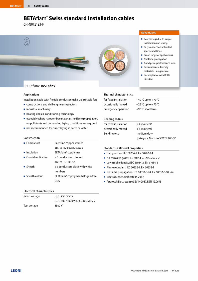
BETAflam® INSTAflex
Applications
Installation cable with flexible conductor make-up, suitable for:■■ constructions and civil engineering sectors ■■ industrial machinery■■ heating and air-conditioning technology ■■ especially where halogen-free materials, no flame propagation,
no pollutants and demanding laying conditions are required■■ not recommended for direct laying in earth or water
Construction
■■ Conductors
■■ Insulation■■ Core identification
■■ Sheath
■■ Sheath colour
Bare fine copper strands
acc. to IEC 60288, class 5
BETAflam® copolymer
≤ 5 conductors coloured
acc. to HD 308 S2
≥ 6 conductors black with white
numbers
BETAflam® copolymer, halogen-free
Grey
Electrical characteristics
Rated voltage
Test voltage
U₀/U 450 / 750 V
U₀/U 600 / 1000 V (for fixed installation)
3500 V
Thermal characteristics
for fixed installation
occasionally moved
Emergency operation
– 40 °C up to + 70 °C
– 25 °C up to + 70 °C
+90 °C shortterm
Bending radius
for fixed installation
occasionally moved
Bending test
> 4 × outer Ø
> 8 × outer Ø
medium duty
(category 2) acc. to SEV TP 20B/3C
Standards / Material properties
■■ Halogen-free: IEC 60754-1, EN 50267-2-1■■ No corrosive gases: IEC 60754-2, EN 50267-2-2■■ Low smoke density: IEC 61034-2, EN 61034-2■■ Flame retardant: IEC 60332-1, EN 60332-1■■ No flame propagation: IEC 60332-3-24, EN 60332-3-10, -24■■ Electrosuisse Certificate IK-2087■■ Approval: Electrosuisse SEV IK-2087, ESTI 12.0695
Advantages
■■ Cost savings due to simple
installation and wiring■■ Easy connection at limited
space conditions■■ Broad range of applications■■ No flame propagation■■ Good price-performance ratio■■ Environmental-friendly
materials; Halogen-free■■ In compliance with RoHS
directive
BETAflam® Swiss standard installation cables CH-N07Z1Z1-F
Safety cablesBETAflam® 38
www.leoni-infrastructure-datacom.com 07. 2013
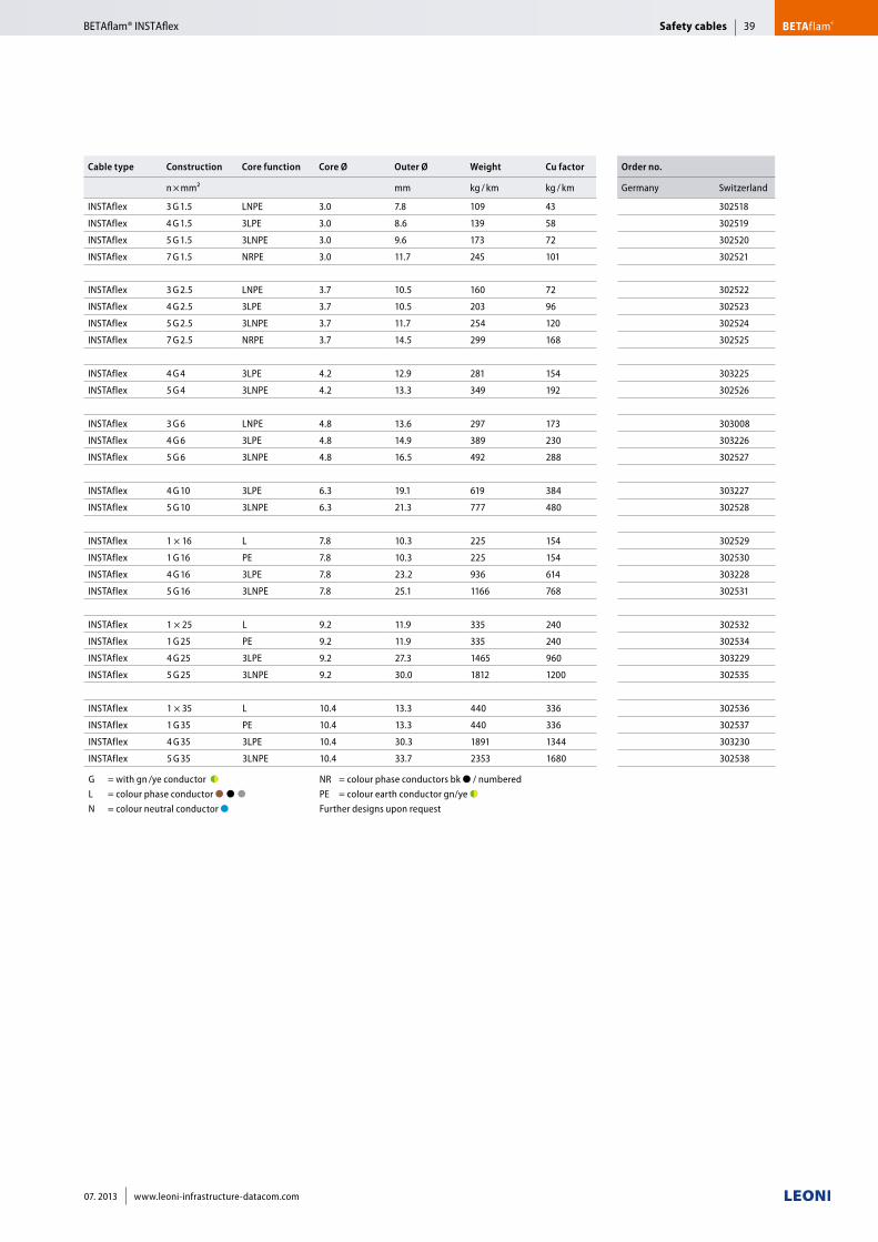
Cable type Construction Core function Core Ø Outer Ø Weight Cu factor Order no.
n × mm² mm kg / km kg / km Germany Switzerland
INSTAflex 3 G 1.5 LNPE 3.0 7.8 109 43 302518
INSTAflex 4 G 1.5 3LPE 3.0 8.6 139 58 302519
INSTAflex 5 G 1.5 3LNPE 3.0 9.6 173 72 302520
INSTAflex 7 G 1.5 NRPE 3.0 11.7 245 101 302521
INSTAflex 3 G 2.5 LNPE 3.7 10.5 160 72 302522
INSTAflex 4 G 2.5 3LPE 3.7 10.5 203 96 302523
INSTAflex 5 G 2.5 3LNPE 3.7 11.7 254 120 302524
INSTAflex 7 G 2.5 NRPE 3.7 14.5 299 168 302525
INSTAflex 4 G 4 3LPE 4.2 12.9 281 154 303225
INSTAflex 5 G 4 3LNPE 4.2 13.3 349 192 302526
INSTAflex 3 G 6 LNPE 4.8 13.6 297 173 303008
INSTAflex 4 G 6 3LPE 4.8 14.9 389 230 303226
INSTAflex 5 G 6 3LNPE 4.8 16.5 492 288 302527
INSTAflex 4 G 10 3LPE 6.3 19.1 619 384 303227
INSTAflex 5 G 10 3LNPE 6.3 21.3 777 480 302528
INSTAflex 1 × 16 L 7.8 10.3 225 154 302529
INSTAflex 1 G 16 PE 7.8 10.3 225 154 302530
INSTAflex 4 G 16 3LPE 7.8 23.2 936 614 303228
INSTAflex 5 G 16 3LNPE 7.8 25.1 1166 768 302531
INSTAflex 1 × 25 L 9.2 11.9 335 240 302532
INSTAflex 1 G 25 PE 9.2 11.9 335 240 302534
INSTAflex 4 G 25 3LPE 9.2 27.3 1465 960 303229
INSTAflex 5 G 25 3LNPE 9.2 30.0 1812 1200 302535
INSTAflex 1 × 35 L 10.4 13.3 440 336 302536
INSTAflex 1 G 35 PE 10.4 13.3 440 336 302537
INSTAflex 4 G 35 3LPE 10.4 30.3 1891 1344 303230
INSTAflex 5 G 35 3LNPE 10.4 33.7 2353 1680 302538
G = with gn /ye conductor ●◗ L = colour phase conductor ●■●■●■ N = colour neutral conductor ●■
NR = colour phase conductors bk ● / numbered PE = colour earth conductor gn/ye ●◗Further designs upon request
Safety cables BETAflam®BETAflam® INSTAflex 39
07. 2013 www.leoni-infrastructure-datacom.com
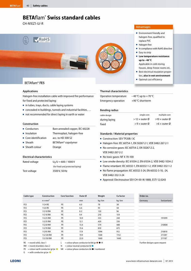
BETAflam® FE5
Applications
Halogen-free installation cable with improved fire performance
for fixed and protected laying:■■ in tubes, trays, ducts, cable laying systems■■ concealed in buildings, tunnels and industrial facilities, …■■ not recommended for direct laying in earth or water
Construction
■■ Conductors■■ Insulation■■ Core identification■■ Sheath■■ Sheath colour
Bare annealed copper, IEC 60228
Thermoplast, halogen-free
acc. to HD 308 S2
BETAflam® copolymer
Orange
Electrical characteristics
Rated voltage
Test voltage
U0/U = 600 / 1000 V
(for fixed und protected laying)
3500 V, 50 Hz
Thermal characteristics
Operation temperature
Emergency operation
– 40 °C up to + 70 °C
+90 °C shortterm
Bending radius
cable design
during laying
fixed
single core multiple core
> 12 × outer Ø >10 × outer Ø
> 9 × outer Ø >6 × outer Ø
Standards / Material properties
■■ Construction: SEV TP20B / 3C■■ Halogen-free: IEC 60754-1, EN 50267-2-1, VDE 0482-267-2-1■■ No corrosive gases: IEC 60754-2, EN 50267-2-2,
VDE 0482-267-2-2■■ No toxic gases: NF X 70-100■■ Low smoke density: IEC 61034-2, EN 61034-2, VDE 0482-1034-2■■ Flame retardant: IEC 60332-1, EN 60332-1-2, VDE 0482-332-1-2■■ No flame propagation: IEC 60332-3-24, EN 60332-3-10, -24,
VDE 0482-332-3-24■■ Approval: Electrosuisse SEV CH-00-IK-1888, ESTI 12.0243
Advantages
■■ Environment friendly and
halogen-free, qualified to
replace PVC■■ Halogen-free■■ In compliance with RoHS directive■■ Easy to strip■■ Low temperature resistance
up to –40 °C
Applicable in cold storing
houses, deep-freeze rooms etc.■■ Best electrical insulation proper-
ties, also in wet environment■■ Optimal cost efficiency
Cable type Construction Core function Outer Ø Weight Cu factor Order no.
n × mm² mm kg / km kg / km Germany Switzerland
FE5 1 G 4 RE PE 6.0 78 38
FE5 1 G 6 RE PE 6.6 93 58
FE5 1 G 10 RM PE 8.3 150 96
FE5 1 G 16 RM PE 9.4 210 154
FE5 1 G 25 RM PE 10.9 333 240 191099
FE5 1 G 35 RM PE 12.1 420 336
FE5 1 G 50 RM PE 13.4 579 480 210808
FE5 1 G 70 RM PE 15.6 810 672
FE5 1 G 95 RM PE 17.9 1096 912 210810
FE5 1 G 120 RM PE 19.9 1368 1152 211287
FE5 1 G 150 RM PE 22.0 1660 1440 211187
RE = round solid, class 1 RM = round stranded, class 2PE = colour earth conductor gr/ye ●◗G = with conductor gr/ye ●◗
L = colour phase conductor br/bk/gr ●■●■●■■ N = colour neutral conductor bl ●■■ NR = colour phase conductors bk ● / numbered
Further designs upon request
BETAflam® Swiss standard cables CH-N1EZ1-U/-R
Safety cablesBETAflam® 40
www.leoni-infrastructure-datacom.com 07. 2013
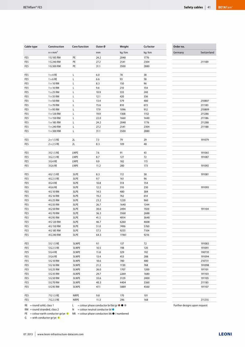
Cable type Construction Core function Outer Ø Weight Cu factor Order no.
n × mm² mm kg / km kg / km Germany Switzerland
FE5 1 G 185 RM PE 24.2 2048 1776
FE5 1 G 240 RM PE 27.2 2541 2304 211189
FE5 1 G 300 RM PE 31.1 3500 2880
FE5 1 × 4 RE L 6.0 78 38
FE5 1 × 6 RE L 6.6 93 58
FE5 1 × 10 RM L 8.3 150 96
FE5 1 × 16 RM L 9.4 210 154
FE5 1 × 25 RM L 10.9 333 240
FE5 1 × 35 RM L 12.1 420 336
FE5 1 × 50 RM L 13.4 579 480 210807
FE5 1 × 70 RM L 15.6 810 672 211183
FE5 1 × 95 RM L 17.9 1096 912 210809
FE5 1 × 120 RM L 19.9 1368 1152 211286
FE5 1 × 150 RM L 22.0 1660 1440 211186
FE5 1 × 185 RM L 24.2 2048 1776 211288
FE5 1 × 240 RM L 27.2 2541 2304 211188
FE5 1 × 300 RM L 31.1 3500 2880
FE5 2 × 1.5 RE 2L 7.3 79 29 191079
FE5 2 × 2.5 RE 2L 8.3 109 48
FE5 3 G 1.5 RE LNPE 7.6 91 43 191065
FE5 3 G 2.5 RE LNPE 8.7 127 72 191087
FE5 3 G 4 RE LNPE 9.9 182 115
FE5 3 G 6 RE LNPE 11.2 280 173 191092
FE5 4 G 1.5 RE 3LPE 8.3 112 58 191081
FE5 4 G 2.5 RE 3LPE 9.7 161 96
FE5 4 G 4 RE 3LPE 10.8 314 154
FE5 4 G 6 RE 3LPE 12.2 310 230 191093
FE5 4 G 10 RM 3LPE 14.5 480 384
FE5 4 G 16 RM 3LPE 19.2 762 614
FE5 4 G 25 RM 3LPE 23.2 1220 960
FE5 4 G 35 RM 3LPE 26.7 1640 1344
FE5 4 G 50 RM 3LPE 30.0 2494 1920 191104
FE5 4 G 70 RM 3LPE 36.3 3568 2688
FE5 4 G 95 RM 3LPE 41.5 4914 3648
FE5 4 G 120 RM 3LPE 46.7 6260 4608
FE5 4 G 150 RM 3LPE 51.0 7496 5760
FE5 4 G 185 RM 3LPE 57.3 9255 7104
FE5 4 G 240 RM 3LPE 64.3 11961 9216
FE5 5 G 1.5 RE 3LNPE 9.1 137 72 191083
FE5 5 G 2.5 RE 3LNPE 10.5 198 120 191091
FE5 5 G 4 RE 3LNPE 11.8 329 192 190735
FE5 5 G 6 RE 3LNPE 13.4 453 288 191094
FE5 5 G 10 RM 3LNPE 18.6 780 480 210731
FE5 5 G 16 RM 3LNPE 21.2 1130 768 191098
FE5 5 G 25 RM 3LNPE 26.0 1707 1200 191101
FE5 5 G 35 RM 3LNPE 29.7 2269 1680 191103
FE5 5 G 50 RM 3LNPE 33.6 3129 2400 191105
FE5 5 G 70 RM 3LNPE 40.3 4404 3360 211185
FE5 5 G 95 RM 3LNPE 47.1 5889 4560 191107
FE5 7 G 1.5 RE NRPE 9.8 170 101
FE5 7 G 2.5 RE NRPE 11.3 296 168 211255
RE = round solid, class 1 RM = round stranded, class 2PE = colour earth conductor gr/ye ●◗G = with conductor gr/ye ●◗
L = colour phase conductor br/bk/gr ●■●■●■■ N = colour neutral conductor bl ●■■ NR = colour phase conductors bk ● / numbered
Further designs upon request
Safety cables BETAflam®41
07. 2013 www.leoni-infrastructure-datacom.com
BETAflam® FE5
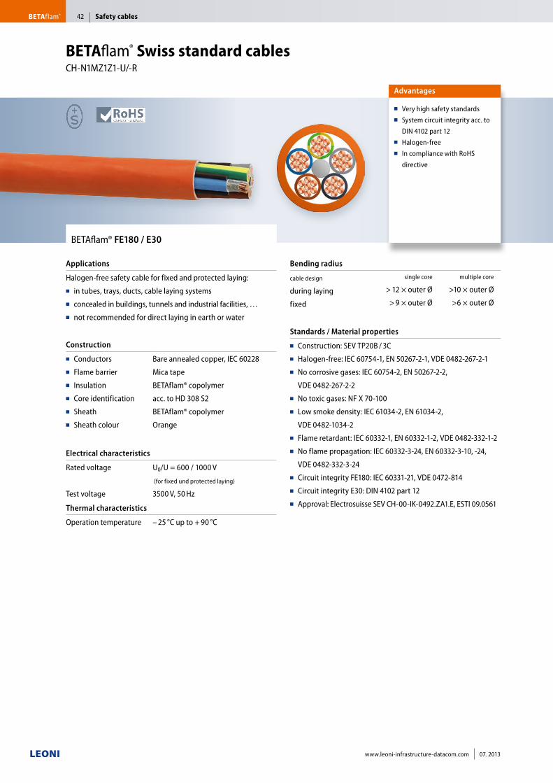
BETAflam® FE180 / E30
Applications
Halogen-free safety cable for fixed and protected laying:■■ in tubes, trays, ducts, cable laying systems■■ concealed in buildings, tunnels and industrial facilities, …■■ not recommended for direct laying in earth or water
Construction
■■ Conductors■■ Flame barrier■■ Insulation■■ Core identification■■ Sheath■■ Sheath colour
Bare annealed copper, IEC 60228
Mica tape
BETAflam® copolymer
acc. to HD 308 S2
BETAflam® copolymer
Orange
Electrical characteristics
Rated voltage
Test voltage
U0/U = 600 / 1000 V
(for fixed und protected laying)
3500 V, 50 Hz
Thermal characteristics
Operation temperature – 25 °C up to + 90 °C
Bending radius
cable design
during laying
fixed
single core multiple core
> 12 × outer Ø >10 × outer Ø
> 9 × outer Ø >6 × outer Ø
Standards / Material properties
■■ Construction: SEV TP20B / 3C■■ Halogen-free: IEC 60754-1, EN 50267-2-1, VDE 0482-267-2-1■■ No corrosive gases: IEC 60754-2, EN 50267-2-2,
VDE 0482-267-2-2■■ No toxic gases: NF X 70-100■■ Low smoke density: IEC 61034-2, EN 61034-2,
VDE 0482-1034-2■■ Flame retardant: IEC 60332-1, EN 60332-1-2, VDE 0482-332-1-2■■ No flame propagation: IEC 60332-3-24, EN 60332-3-10, -24,
VDE 0482-332-3-24■■ Circuit integrity FE180: IEC 60331-21, VDE 0472-814■■ Circuit integrity E30: DIN 4102 part 12■■ Approval: Electrosuisse SEV CH-00-IK-0492.ZA1.E, ESTI 09.0561
Advantages
■■ Very high safety standards■■ System circuit integrity acc. to
DIN 4102 part 12■■ Halogen-free■■ In compliance with RoHS
directive
BETAflam® Swiss standard cables CH-N1MZ1Z1-U/-R
Safety cablesBETAflam® 42
www.leoni-infrastructure-datacom.com 07. 2013
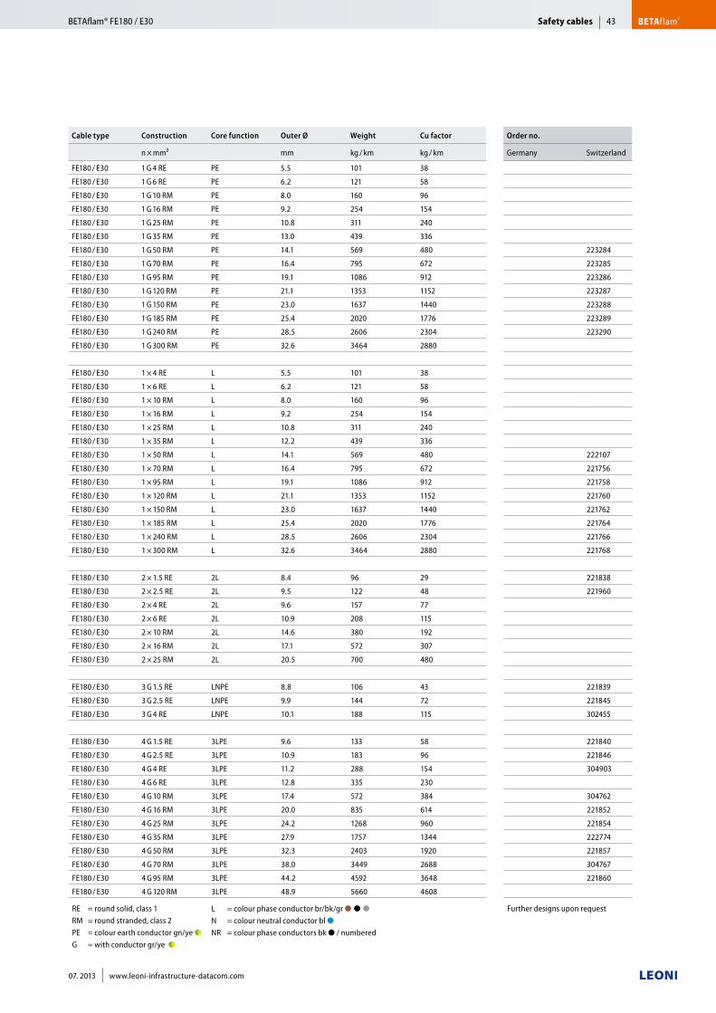
Cable type Construction Core function Outer Ø Weight Cu factor Order no.
n × mm² mm kg / km kg / km Germany Switzerland
FE180 / E30 1 G 4 RE PE 5.5 101 38
FE180 / E30 1 G 6 RE PE 6.2 121 58
FE180 / E30 1 G 10 RM PE 8.0 160 96
FE180 / E30 1 G 16 RM PE 9.2 254 154
FE180 / E30 1 G 25 RM PE 10.8 311 240
FE180 / E30 1 G 35 RM PE 13.0 439 336
FE180 / E30 1 G 50 RM PE 14.1 569 480 223284
FE180 / E30 1 G 70 RM PE 16.4 795 672 223285
FE180 / E30 1 G 95 RM PE 19.1 1086 912 223286
FE180 / E30 1 G 120 RM PE 21.1 1353 1152 223287
FE180 / E30 1 G 150 RM PE 23.0 1637 1440 223288
FE180 / E30 1 G 185 RM PE 25.4 2020 1776 223289
FE180 / E30 1 G 240 RM PE 28.5 2606 2304 223290
FE180 / E30 1 G 300 RM PE 32.6 3464 2880
FE180 / E30 1 × 4 RE L 5.5 101 38
FE180 / E30 1 × 6 RE L 6.2 121 58
FE180 / E30 1 × 10 RM L 8.0 160 96
FE180 / E30 1 × 16 RM L 9.2 254 154
FE180 / E30 1 × 25 RM L 10.8 311 240
FE180 / E30 1 × 35 RM L 12.2 439 336
FE180 / E30 1 × 50 RM L 14.1 569 480 222107
FE180 / E30 1 × 70 RM L 16.4 795 672 221756
FE180 / E30 1 × 95 RM L 19.1 1086 912 221758
FE180 / E30 1 × 120 RM L 21.1 1353 1152 221760
FE180 / E30 1 × 150 RM L 23.0 1637 1440 221762
FE180 / E30 1 × 185 RM L 25.4 2020 1776 221764
FE180 / E30 1 × 240 RM L 28.5 2606 2304 221766
FE180 / E30 1 × 300 RM L 32.6 3464 2880 221768
FE180 / E30 2 × 1.5 RE 2L 8.4 96 29 221838
FE180 / E30 2 × 2.5 RE 2L 9.5 122 48 221960
FE180 / E30 2 × 4 RE 2L 9.6 157 77
FE180 / E30 2 × 6 RE 2L 10.9 208 115
FE180 / E30 2 × 10 RM 2L 14.6 380 192
FE180 / E30 2 × 16 RM 2L 17.1 572 307
FE180 / E30 2 × 25 RM 2L 20.5 700 480
FE180 / E30 3 G 1.5 RE LNPE 8.8 106 43 221839
FE180 / E30 3 G 2.5 RE LNPE 9.9 144 72 221845
FE180 / E30 3 G 4 RE LNPE 10.1 188 115 302455
FE180 / E30 4 G 1.5 RE 3LPE 9.6 133 58 221840
FE180 / E30 4 G 2.5 RE 3LPE 10.9 183 96 221846
FE180 / E30 4 G 4 RE 3LPE 11.2 288 154 304903
FE180 / E30 4 G 6 RE 3LPE 12.8 335 230
FE180 / E30 4 G 10 RM 3LPE 17.4 572 384 304762
FE180 / E30 4 G 16 RM 3LPE 20.0 835 614 221852
FE180 / E30 4 G 25 RM 3LPE 24.2 1268 960 221854
FE180 / E30 4 G 35 RM 3LPE 27.9 1757 1344 222774
FE180 / E30 4 G 50 RM 3LPE 32.3 2403 1920 221857
FE180 / E30 4 G 70 RM 3LPE 38.0 3449 2688 304767
FE180 / E30 4 G 95 RM 3LPE 44.2 4592 3648 221860
FE180 / E30 4 G 120 RM 3LPE 48.9 5660 4608
RE = round solid, class 1 RM = round stranded, class 2PE = colour earth conductor gn/ye ●◗G = with conductor gr/ye ●◗
L = colour phase conductor br/bk/gr ●■●■●■■ N = colour neutral conductor bl ●■■ NR = colour phase conductors bk ● / numbered
Further designs upon request
Safety cables BETAflam®43
07. 2013 www.leoni-infrastructure-datacom.com
BETAflam® FE180 / E30
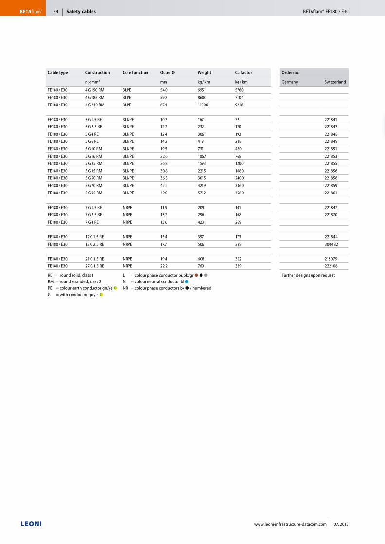
Cable type Construction Core function Outer Ø Weight Cu factor Order no.
n × mm² mm kg / km kg / km Germany Switzerland
FE180 / E30 4 G 150 RM 3LPE 54.0 6951 5760
FE180 / E30 4 G 185 RM 3LPE 59.2 8600 7104
FE180 / E30 4 G 240 RM 3LPE 67.4 11000 9216
FE180 / E30 5 G 1.5 RE 3LNPE 10.7 167 72 221841
FE180 / E30 5 G 2.5 RE 3LNPE 12.2 232 120 221847
FE180 / E30 5 G 4 RE 3LNPE 12.4 306 192 221848
FE180 / E30 5 G 6 RE 3LNPE 14.2 419 288 221849
FE180 / E30 5 G 10 RM 3LNPE 19.5 731 480 221851
FE180 / E30 5 G 16 RM 3LNPE 22.6 1067 768 221853
FE180 / E30 5 G 25 RM 3LNPE 26.8 1593 1200 221855
FE180 / E30 5 G 35 RM 3LNPE 30.8 2215 1680 221856
FE180 / E30 5 G 50 RM 3LNPE 36.3 3015 2400 221858
FE180 / E30 5 G 70 RM 3LNPE 42.2 4219 3360 221859
FE180 / E30 5 G 95 RM 3LNPE 49.0 5712 4560 221861
FE180 / E30 7 G 1.5 RE NRPE 11.5 209 101 221842
FE180 / E30 7 G 2.5 RE NRPE 13.2 296 168 221870
FE180 / E30 7 G 4 RE NRPE 13.6 423 269
FE180 / E30 12 G 1.5 RE NRPE 15.4 357 173 221844
FE180 / E30 12 G 2.5 RE NRPE 17.7 506 288 300482
FE180 / E30 21 G 1.5 RE NRPE 19.4 608 302 215079
FE180 / E30 27 G 1.5 RE NRPE 22.2 769 389 222106
RE = round solid, class 1 RM = round stranded, class 2PE = colour earth conductor gn/ye ●◗G = with conductor gr/ye ●◗
L = colour phase conductor br/bk/gr ●■●■●■■ N = colour neutral conductor bl ●■■ NR = colour phase conductors bk ● / numbered
Further designs upon request
Safety cablesBETAflam® BETAflam® FE180 / E3044
www.leoni-infrastructure-datacom.com 07. 2013
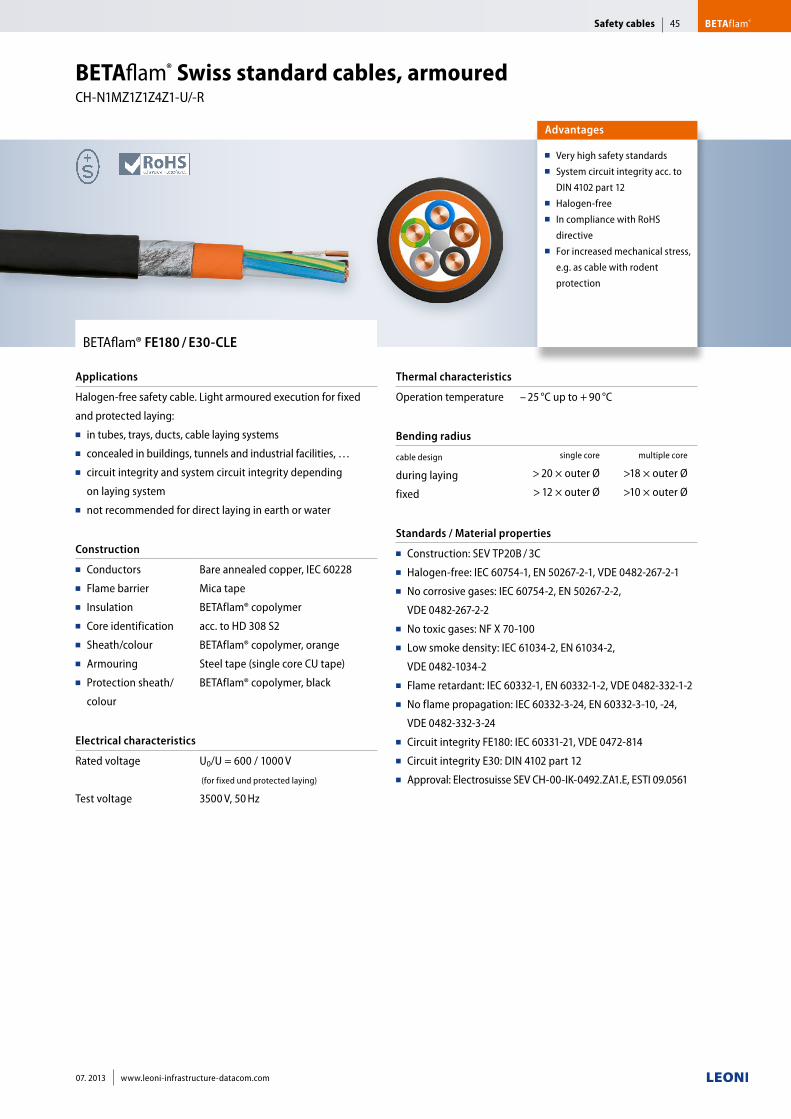
BETAflam® FE180 / E30-CLE
Applications
Halogen-free safety cable. Light armoured execution for fixed
and protected laying:■■ in tubes, trays, ducts, cable laying systems■■ concealed in buildings, tunnels and industrial facilities, …■■ circuit integrity and system circuit integrity depending
on laying system■■ not recommended for direct laying in earth or water
Construction
■■ Conductors■■ Flame barrier■■ Insulation■■ Core identification■■ Sheath/colour■■ Armouring ■■ Protection sheath/
colour
Bare annealed copper, IEC 60228
Mica tape
BETAflam® copolymer
acc. to HD 308 S2
BETAflam® copolymer, orange
Steel tape (single core CU tape)
BETAflam® copolymer, black
Electrical characteristics
Rated voltage
Test voltage
U0/U = 600 / 1000 V
(for fixed und protected laying)
3500 V, 50 Hz
Thermal characteristics
Operation temperature – 25 °C up to + 90 °C
Bending radius
cable design
during laying
fixed
single core multiple core
> 20 × outer Ø >18 × outer Ø
> 12 × outer Ø >10 × outer Ø
Standards / Material properties
■■ Construction: SEV TP20B / 3C■■ Halogen-free: IEC 60754-1, EN 50267-2-1, VDE 0482-267-2-1■■ No corrosive gases: IEC 60754-2, EN 50267-2-2,
VDE 0482-267-2-2■■ No toxic gases: NF X 70-100■■ Low smoke density: IEC 61034-2, EN 61034-2,
VDE 0482-1034-2■■ Flame retardant: IEC 60332-1, EN 60332-1-2, VDE 0482-332-1-2■■ No flame propagation: IEC 60332-3-24, EN 60332-3-10, -24,
VDE 0482-332-3-24■■ Circuit integrity FE180: IEC 60331-21, VDE 0472-814■■ Circuit integrity E30: DIN 4102 part 12■■ Approval: Electrosuisse SEV CH-00-IK-0492.ZA1.E, ESTI 09.0561
Advantages
■■ Very high safety standards■■ System circuit integrity acc. to
DIN 4102 part 12■■ Halogen-free■■ In compliance with RoHS
directive ■■ For increased mechanical stress,
e.g. as cable with rodent
protection
BETAflam® Swiss standard cables, armoured CH-N1MZ1Z1Z4Z1-U/-R
Safety cables BETAflam®45
07. 2013 www.leoni-infrastructure-datacom.com
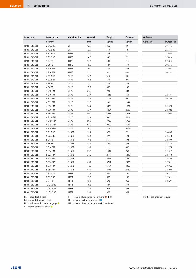
Cable type Construction Core function Outer Ø Weight Cu factor Order no.
n × mm² mm kg / km kg / km Germany Switzerland
FE180 / E30-CLE 2 × 1.5 RE 2L 12.8 255 29 301445
FE180 / E30-CLE 2 × 2.5 RE 2L 13.9 318 48 222517
FE180 / E30-CLE 3 G 1.5 RE LNPE 13.2 288 43 224050
FE180 / E30-CLE 3 G 2.5 RE LNPE 14.3 347 72 217088
FE180 / E30-CLE 3 G 4 RE LNPE 14.5 401 115 217400
FE180 / E30-CLE 3 G 6 RE LNPE 15.8 487 173 303556
FE180 / E30-CLE 3 G 10 RM LNPE 20.0 737 288 226080
FE180 / E30-CLE 3 G 16 RM LNPE 22.5 921 461 303557
FE180 / E30-CLE 4 G 1.5 RE 3LPE 14.0 314 58
FE180 / E30-CLE 4 G 2.5 RE 3LPE 15.3 374 96
FE180 / E30-CLE 4 G 4 RE 3LPE 15.6 426 154
FE180 / E30-CLE 4 G 6 RE 3LPE 17.2 660 230
FE180 / E30-CLE 4 G 10 RM 3LPE 21.8 920 384
FE180 / E30-CLE 4 G 16 RM 3LPE 24.4 1228 614 224631
FE180 / E30-CLE 4 G 25 RM 3LPE 28.6 1733 960 304765
FE180 / E30-CLE 4 G 35 RM 3LPE 32.3 2311 1344
FE180 / E30-CLE 4 G 50 RM 3LPE 36.7 3028 1920 224024
FE180 / E30-CLE 4 G 70 RM 3LPE 42.4 4054 2688 226082
FE180 / E30-CLE 4 G 95 RM 3LPE 49.0 5485 3648 226081
FE180 / E30-CLE 4 G 120 RM 3LPE 53.9 6300 4608
FE180 / E30-CLE 4 G 150 RM 3LPE 59.8 7700 5760
FE180 / E30-CLE 4 G 185 RM 3LPE 65.0 9800 7104
FE180 / E30-CLE 4 G 240 RM 3LPE 74.0 12000 9216
FE180 / E30-CLE 5 G 1.5 RE 3LNPE 15.1 372 72 301446
FE180 / E30-CLE 5 G 2.5 RE 3LNPE 16.6 477 120 222518
FE180 / E30-CLE 5 G 4 RE 3LNPE 16.8 555 192 223897
FE180 / E30-CLE 5 G 6 RE 3LNPE 18.6 706 288 222176
FE180 / E30-CLE 5 G 10 RM 3LNPE 23.9 1111 480 222775
FE180 / E30-CLE 5 G 16 RM 3LNPE 27.0 1501 768 222512
FE180 / E30-CLE 5 G 25 RM 3LNPE 31.2 2115 1200 220518
FE180 / E30-CLE 5 G 35 RM 3LNPE 35.2 2813 1680 224807
FE180 / E30-CLE 5 G 50 RM 3LNPE 40.7 3719 2400 217101
FE180 / E30-CLE 5 G 70 RM 3LNPE 47.2 5157 3360 302965
FE180 / E30-CLE 5 G 95 RM 3LNPE 54.0 6785 4560 224092
FE180 / E30-CLE 7 G 1.5 RE NRPE 15.9 521 101 303157
FE180 / E30-CLE 7 G 2.5 RE NRPE 17.6 560 168 217102
FE180 / E30-CLE 7 G 4 RE NRPE 18.0 679 269 300677
FE180 / E30-CLE 12 G 1.5 RE NRPE 19.8 644 173
FE180 / E30-CLE 12 G 2.5 RE NRPE 22.1 977 288
FE180 / E30-CLE 21 G 1.5 RE NRPE 23.8 963 302
RE = round solid, class 1 RM = round stranded, class 2PE = colour earth conductor gn/ye ●◗G = with conductor gr/ye ●◗
L = colour phase conductor br/bk/gr ●■●■●■■ N = colour neutral conductor bl ●■■ NR = colour phase conductors bk ● / numbered
Further designs upon request
Safety cablesBETAflam® BETAflam® FE180 / E30-CLE46
www.leoni-infrastructure-datacom.com 07. 2013
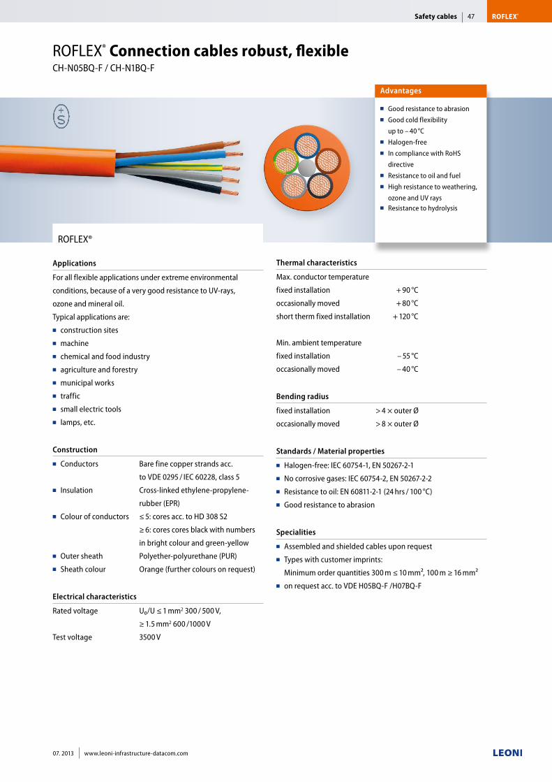
ROFLEX®
Applications
For all flexible applications under extreme environmental
conditions, because of a very good resistance to UV-rays,
ozone and mineral oil.
Typical applications are:■■ construction sites■■ machine■■ chemical and food industry■■ agriculture and forestry ■■ municipal works■■ traffic■■ small electric tools■■ lamps, etc.
Construction
■■ Conductors
■■ Insulation
■■ Colour of conductors
■■ Outer sheath■■ Sheath colour
Bare fine copper strands acc.
to VDE 0295 / IEC 60228, class 5
Cross-linked ethylene-propylene-
rubber (EPR)
≤ 5: cores acc. to HD 308 S2
≥ 6: cores cores black with numbers
in bright colour and green-yellow
Polyether-polyurethane (PUR)
Orange (further colours on request)
Electrical characteristics
Rated voltage
Test voltage
U₀/U ≤ 1 mm2 300 / 500 V,
≥ 1.5 mm2 600 /1000 V
3500 V
Thermal characteristics
Max. conductor temperature
fixed installation + 90 °C
occasionally moved + 80 °C
short therm fixed installation + 120 °C
Min. ambient temperature
fixed installation – 55 °C
occasionally moved – 40 °C
Bending radius
fixed installation
occasionally moved
> 4 × outer Ø
> 8 × outer Ø
Standards / Material properties
■■ Halogen-free: IEC 60754-1, EN 50267-2-1■■ No corrosive gases: IEC 60754-2, EN 50267-2-2■■ Resistance to oil: EN 60811-2-1 (24 hrs / 100 °C)■■ Good resistance to abrasion
Specialities
■■ Assembled and shielded cables upon request■■ Types with customer imprints:
Minimum order quantities 300 m ≤ 10 mm², 100 m ≥ 16 mm²■■ on request acc. to VDE H05BQ-F /H07BQ-F
Advantages
■■ Good resistance to abrasion■■ Good cold flexibility
up to – 40 °C■■ Halogen-free■■ In compliance with RoHS
directive ■■ Resistance to oil and fuel■■ High resistance to weathering,
ozone and UV rays■■ Resistance to hydrolysis
ROFLEX® Connection cables robust, flexible CH-N05BQ-F / CH-N1BQ-F
Safety cables ROFLEX®47
07. 2013 www.leoni-infrastructure-datacom.com
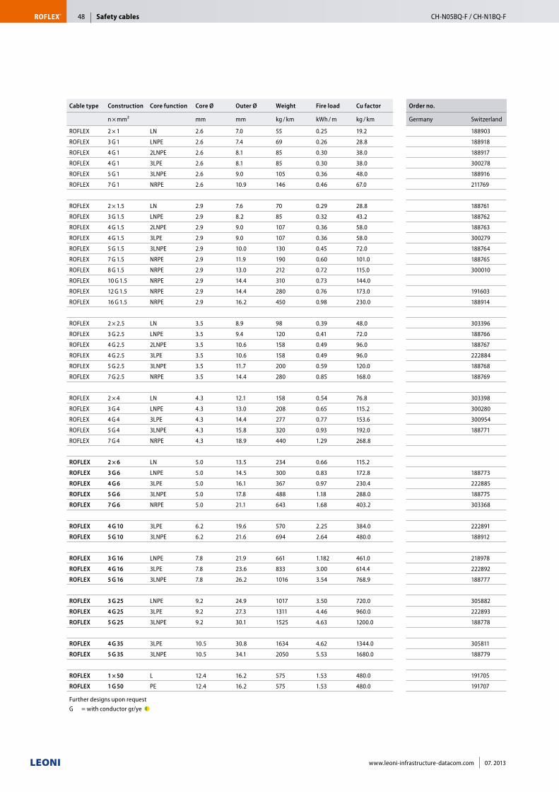
Cable type Construction Core function Core Ø Outer Ø Weight Fire load Cu factor Order no.
n × mm² mm mm kg / km kWh / m kg / km Germany Switzerland
ROFLEX 2 × 1 LN 2.6 7.0 55 0.25 19.2 188903
ROFLEX 3 G 1 LNPE 2.6 7.4 69 0.26 28.8 188918
ROFLEX 4 G 1 2LNPE 2.6 8.1 85 0.30 38.0 188917
ROFLEX 4 G 1 3LPE 2.6 8.1 85 0.30 38.0 300278
ROFLEX 5 G 1 3LNPE 2.6 9.0 105 0.36 48.0 188916
ROFLEX 7 G 1 NRPE 2.6 10.9 146 0.46 67.0 211769
ROFLEX 2 × 1.5 LN 2.9 7.6 70 0.29 28.8 188761
ROFLEX 3 G 1.5 LNPE 2.9 8.2 85 0.32 43.2 188762
ROFLEX 4 G 1.5 2LNPE 2.9 9.0 107 0.36 58.0 188763
ROFLEX 4 G 1.5 3LPE 2.9 9.0 107 0.36 58.0 300279
ROFLEX 5 G 1.5 3LNPE 2.9 10.0 130 0.45 72.0 188764
ROFLEX 7 G 1.5 NRPE 2.9 11.9 190 0.60 101.0 188765
ROFLEX 8 G 1.5 NRPE 2.9 13.0 212 0.72 115.0 300010
ROFLEX 10 G 1.5 NRPE 2.9 14.4 310 0.73 144.0
ROFLEX 12 G 1.5 NRPE 2.9 14.4 280 0.76 173.0 191603
ROFLEX 16 G 1.5 NRPE 2.9 16.2 450 0.98 230.0 188914
ROFLEX 2 × 2.5 LN 3.5 8.9 98 0.39 48.0 303396
ROFLEX 3 G 2.5 LNPE 3.5 9.4 120 0.41 72.0 188766
ROFLEX 4 G 2.5 2LNPE 3.5 10.6 158 0.49 96.0 188767
ROFLEX 4 G 2.5 3LPE 3.5 10.6 158 0.49 96.0 222884
ROFLEX 5 G 2.5 3LNPE 3.5 11.7 200 0.59 120.0 188768
ROFLEX 7 G 2.5 NRPE 3.5 14.4 280 0.85 168.0 188769
ROFLEX 2 × 4 LN 4.3 12.1 158 0.54 76.8 303398
ROFLEX 3 G 4 LNPE 4.3 13.0 208 0.65 115.2 300280
ROFLEX 4 G 4 3LPE 4.3 14.4 277 0.77 153.6 300954
ROFLEX 5 G 4 3LNPE 4.3 15.8 320 0.93 192.0 188771
ROFLEX 7 G 4 NRPE 4.3 18.9 440 1.29 268.8
ROFLEX 2 × 6 LN 5.0 13.5 234 0.66 115.2
ROFLEX 3 G 6 LNPE 5.0 14.5 300 0.83 172.8 188773
ROFLEX 4 G 6 3LPE 5.0 16.1 367 0.97 230.4 222885
ROFLEX 5 G 6 3LNPE 5.0 17.8 488 1.18 288.0 188775
ROFLEX 7 G 6 NRPE 5.0 21.1 643 1.68 403.2 303368
ROFLEX 4 G 10 3LPE 6.2 19.6 570 2.25 384.0 222891
ROFLEX 5 G 10 3LNPE 6.2 21.6 694 2.64 480.0 188912
ROFLEX 3 G 16 LNPE 7.8 21.9 661 1.182 461.0 218978
ROFLEX 4 G 16 3LPE 7.8 23.6 833 3.00 614.4 222892
ROFLEX 5 G 16 3LNPE 7.8 26.2 1016 3.54 768.9 188777
ROFLEX 3 G 25 LNPE 9.2 24.9 1017 3.50 720.0 305882
ROFLEX 4 G 25 3LPE 9.2 27.3 1311 4.46 960.0 222893
ROFLEX 5 G 25 3LNPE 9.2 30.1 1525 4.63 1200.0 188778
ROFLEX 4 G 35 3LPE 10.5 30.8 1634 4.62 1344.0 305811
ROFLEX 5 G 35 3LNPE 10.5 34.1 2050 5.53 1680.0 188779
ROFLEX 1 × 50 L 12.4 16.2 575 1.53 480.0 191705
ROFLEX 1 G 50 PE 12.4 16.2 575 1.53 480.0 191707
Further designs upon request G = with conductor gr/ye ●◗
Safety cablesROFLEX® CH-N05BQ-F / CH-N1BQ-F48
www.leoni-infrastructure-datacom.com 07. 2013
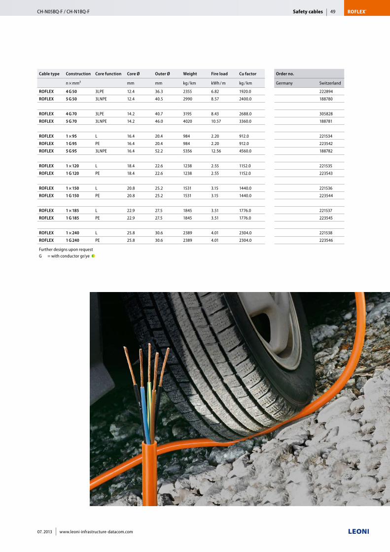
Cable type Construction Core function Core Ø Outer Ø Weight Fire load Cu factor Order no.
n × mm² mm mm kg / km kWh / m kg / km Germany Switzerland
ROFLEX 4 G 50 3LPE 12.4 36.3 2355 6.82 1920.0 222894
ROFLEX 5 G 50 3LNPE 12.4 40.5 2990 8.57 2400.0 188780
ROFLEX 4 G 70 3LPE 14.2 40.7 3195 8.43 2688.0 305828
ROFLEX 5 G 70 3LNPE 14.2 46.0 4020 10.57 3360.0 188781
ROFLEX 1 × 95 L 16.4 20.4 984 2.20 912.0 221534
ROFLEX 1 G 95 PE 16.4 20.4 984 2.20 912.0 223542
ROFLEX 5 G 95 3LNPE 16.4 52.2 5356 12.56 4560.0 188782
ROFLEX 1 × 120 L 18.4 22.6 1238 2.55 1152.0 221535
ROFLEX 1 G 120 PE 18.4 22.6 1238 2.55 1152.0 223543
ROFLEX 1 × 150 L 20.8 25.2 1531 3.15 1440.0 221536
ROFLEX 1 G 150 PE 20.8 25.2 1531 3.15 1440.0 223544
ROFLEX 1 × 185 L 22.9 27.5 1845 3.51 1776.0 221537
ROFLEX 1 G 185 PE 22.9 27.5 1845 3.51 1776.0 223545
ROFLEX 1 × 240 L 25.8 30.6 2389 4.01 2304.0 221538
ROFLEX 1 G 240 PE 25.8 30.6 2389 4.01 2304.0 223546
Further designs upon request G = with conductor gr/ye ●◗
Safety cables ROFLEX®CH-N05BQ-F / CH-N1BQ-F 49
07. 2013 www.leoni-infrastructure-datacom.com
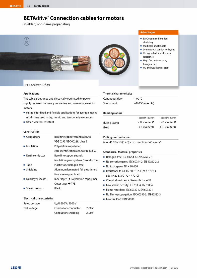
BETAdrive® Connection cables for motors shielded, non-flame propagating
Safety cablesBETAdrive® 50
www.leoni-infrastructure-datacom.com 07. 2013
Advantages
■■ EMC optimised braided shielding
■■ Multicore and flexible■■ Symmetrical conductor layout■■ Very good oil and chemical
resistance■■ High fire performance,
halogen-free■■ UV and weather resistant
BETAdrive® C-flex
Applications
This cable is designed and electrically optimised for power
supply between frequency converters and low-voltage electric
motors:■■ suitable for fixed and flexible applications for average mecha-
nical stress used in dry, humid and temporarily wet rooms ■■ UV an weather resistant
Construction
■■ Conductors
■■ Insulation
■■ Earth conductor
■■ Tape■■ Shielding
■■ Dual layer sheath
■■ Sheath colour
Bare fine copper strands acc. to
VDE 0295 / IEC 60228, class 5
Polyolefine copolymer,
core identification acc. to HD 308 S2
Bare fine copper strands,
insulation green-yellow, 3 conductors
Plastic tape halogen-free
Aluminum laminated foil plus tinned
fine wire copper braid
Inner layer■➔ Polyolefine copolymer
Outer layer ➔ TPE
Black
Electrical characteristics
Rated voltage
Test voltage
U₀/U 600 V / 1000 V
Conductor / conductor 3500 V
Conductor / shielding 2500 V
Thermal characteristics
Continuous duty
Short-circuit
+ 90 °C
+160 °C (max. 5 s)
Bending radius
during laying
fixed
cable Ø < 30 mm cable Ø > 30 mm
> 12 × outer Ø >15 × outer Ø
> 8 × outer Ø >10 × outer Ø
Pulling on conductors
Max. 40 N/mm2 ((3 + 3) × cross section × 40 N/mm2)
Standards / Material properties
■■ Halogen-free: IEC 60754-1, EN 50267-2-1■■ No corrosive gases: IEC 60754-2, EN 50267-2-2■■ No toxic gases: NF X 70-100■■ Resistance to oil: EN 60811-2-1 (24 h / 70 °C),
SEV TP 20 B/3 C (72 h / 70 °C)■■ Chemical resistance: See table page 54 ■■ Low smoke density: IEC 61034, EN 61034■■ Flame retardant: IEC 60332-1, EN 60332-1■■ No flame propagation: IEC 60332-3, EN 60332-3■■ Low fire load: DIN 51900
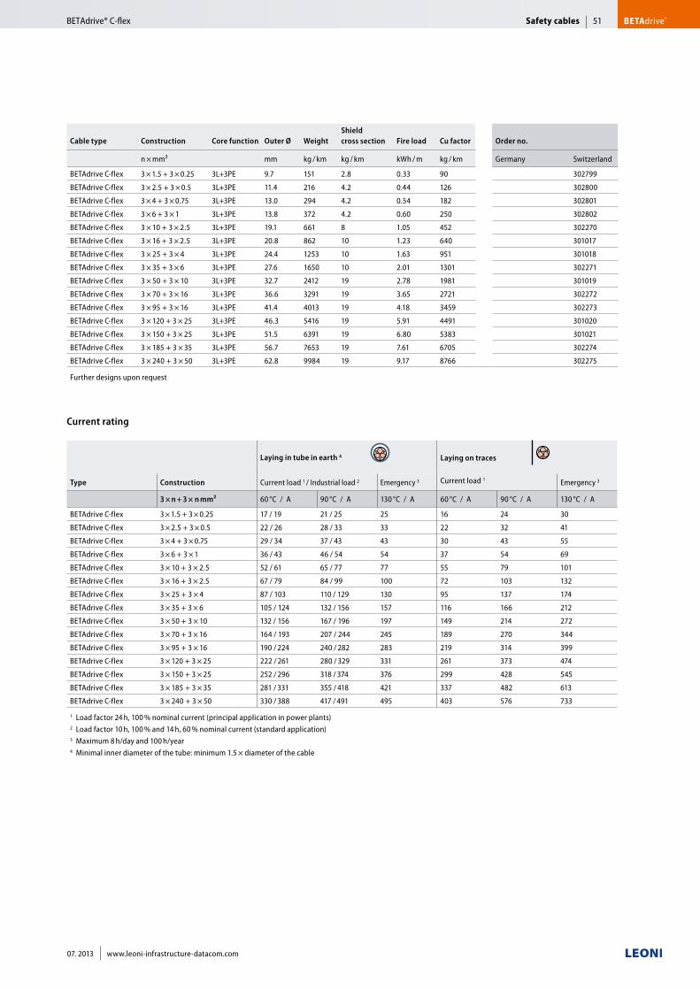
Cable type Construction Core function Outer Ø WeightShield cross section Fire load Cu factor Order no.
n × mm² mm kg / km kg / km kWh / m kg / km Germany Switzerland
BETAdrive C-flex 3 × 1.5 + 3 × 0.25 3L+3PE 9.7 151 2.8 0.33 90 302799
BETAdrive C-flex 3 × 2.5 + 3 × 0.5 3L+3PE 11.4 216 4.2 0.44 126 302800
BETAdrive C-flex 3 × 4 + 3 × 0.75 3L+3PE 13.0 294 4.2 0.54 182 302801
BETAdrive C-flex 3 × 6 + 3 × 1 3L+3PE 13.8 372 4.2 0.60 250 302802
BETAdrive C-flex 3 × 10 + 3 × 2.5 3L+3PE 19.1 661 8 1.05 452 302270
BETAdrive C-flex 3 × 16 + 3 × 2.5 3L+3PE 20.8 862 10 1.23 640 301017
BETAdrive C-flex 3 × 25 + 3 × 4 3L+3PE 24.4 1253 10 1.63 951 301018
BETAdrive C-flex 3 × 35 + 3 × 6 3L+3PE 27.6 1650 10 2.01 1301 302271
BETAdrive C-flex 3 × 50 + 3 × 10 3L+3PE 32.7 2412 19 2.78 1981 301019
BETAdrive C-flex 3 × 70 + 3 × 16 3L+3PE 36.6 3291 19 3.65 2721 302272
BETAdrive C-flex 3 × 95 + 3 × 16 3L+3PE 41.4 4013 19 4.18 3459 302273
BETAdrive C-flex 3 × 120 + 3 × 25 3L+3PE 46.3 5416 19 5.91 4491 301020
BETAdrive C-flex 3 × 150 + 3 × 25 3L+3PE 51.5 6391 19 6.80 5383 301021
BETAdrive C-flex 3 × 185 + 3 × 35 3L+3PE 56.7 7653 19 7.61 6705 302274
BETAdrive C-flex 3 × 240 + 3 × 50 3L+3PE 62.8 9984 19 9.17 8766 302275
Further designs upon request
Laying in tube in earth 4 Laying on traces
Type Construction Current load 1 / Industrial load 2 Emergency 3 Current load 1 Emergency 3
3 × n + 3 × n mm² 60 °C / A 90 °C / A 130 °C / A 60 °C / A 90 °C / A 130 °C / A
BETAdrive C-flex 3 × 1.5 + 3 × 0.25 17 / 19 21 / 25 25 16 24 30
BETAdrive C-flex 3 × 2.5 + 3 × 0.5 22 / 26 28 / 33 33 22 32 41
BETAdrive C-flex 3 × 4 + 3 × 0.75 29 / 34 37 / 43 43 30 43 55
BETAdrive C-flex 3 × 6 + 3 × 1 36 / 43 46 / 54 54 37 54 69
BETAdrive C-flex 3 × 10 + 3 × 2.5 52 / 61 65 / 77 77 55 79 101
BETAdrive C-flex 3 × 16 + 3 × 2.5 67 / 79 84 / 99 100 72 103 132
BETAdrive C-flex 3 × 25 + 3 × 4 87 / 103 110 / 129 130 95 137 174
BETAdrive C-flex 3 × 35 + 3 × 6 105 / 124 132 / 156 157 116 166 212
BETAdrive C-flex 3 × 50 + 3 × 10 132 / 156 167 / 196 197 149 214 272
BETAdrive C-flex 3 × 70 + 3 × 16 164 / 193 207 / 244 245 189 270 344
BETAdrive C-flex 3 × 95 + 3 × 16 190 / 224 240 / 282 283 219 314 399
BETAdrive C-flex 3 × 120 + 3 × 25 222 / 261 280 / 329 331 261 373 474
BETAdrive C-flex 3 × 150 + 3 × 25 252 / 296 318 / 374 376 299 428 545
BETAdrive C-flex 3 × 185 + 3 × 35 281 / 331 355 / 418 421 337 482 613
BETAdrive C-flex 3 × 240 + 3 × 50 330 / 388 417 / 491 495 403 576 733
1 Load factor 24 h, 100 % nominal current (principal application in power plants)2 Load factor 10 h, 100 % and 14 h, 60 % nominal current (standard application)3 Maximum 8 h/day and 100 h/year 4 Minimal inner diameter of the tube: minimum 1.5 × diameter of the cable
Current rating
Safety cables BETAdrive®BETAdrive® C-flex 51
07. 2013 www.leoni-infrastructure-datacom.com
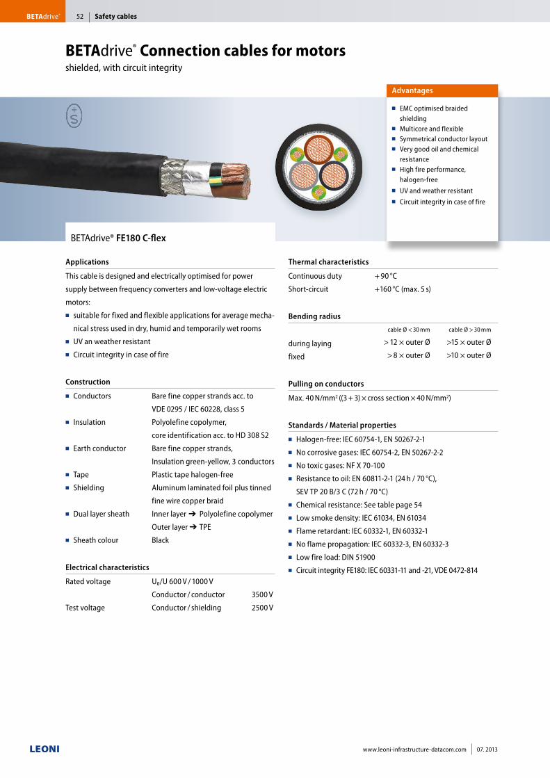
BETAdrive® FE180 C-flex
Applications
This cable is designed and electrically optimised for power
supply between frequency converters and low-voltage electric
motors:■■ suitable for fixed and flexible applications for average mecha-
nical stress used in dry, humid and temporarily wet rooms ■■ UV an weather resistant■■ Circuit integrity in case of fire
Construction
■■ Conductors
■■ Insulation
■■ Earth conductor
■■ Tape■■ Shielding
■■ Dual layer sheath
■■ Sheath colour
Bare fine copper strands acc. to
VDE 0295 / IEC 60228, class 5
Polyolefine copolymer,
core identification acc. to HD 308 S2
Bare fine copper strands,
Insulation green-yellow, 3 conductors
Plastic tape halogen-free
Aluminum laminated foil plus tinned
fine wire copper braid
Inner layer■➔ Polyolefine copolymer
Outer layer ➔■TPE
Black
Electrical characteristics
Rated voltage
Test voltage
U₀/U 600 V / 1000 V
Conductor / conductor 3500 V
Conductor / shielding 2500 V
Thermal characteristics
Continuous duty
Short-circuit
+ 90 °C
+160 °C (max. 5 s)
Bending radius
during laying
fixed
cable Ø < 30 mm cable Ø > 30 mm
> 12 × outer Ø >15 × outer Ø
> 8 × outer Ø >10 × outer Ø
Pulling on conductors
Max. 40 N/mm2 ((3 + 3) × cross section × 40 N/mm2)
Standards / Material properties
■■ Halogen-free: IEC 60754-1, EN 50267-2-1■■ No corrosive gases: IEC 60754-2, EN 50267-2-2■■ No toxic gases: NF X 70-100■■ Resistance to oil: EN 60811-2-1 (24 h / 70 °C),
SEV TP 20 B/3 C (72 h / 70 °C)■■ Chemical resistance: See table page 54■■ Low smoke density: IEC 61034, EN 61034■■ Flame retardant: IEC 60332-1, EN 60332-1■■ No flame propagation: IEC 60332-3, EN 60332-3■■ Low fire load: DIN 51900 ■■ Circuit integrity FE180: IEC 60331-11 and -21, VDE 0472-814
Advantages
■■ EMC optimised braided shielding
■■ Multicore and flexible■■ Symmetrical conductor layout■■ Very good oil and chemical
resistance■■ High fire performance,
halogen-free■■ UV and weather resistant■■ Circuit integrity in case of fire
BETAdrive® Connection cables for motors shielded, with circuit integrity
Safety cablesBETAdrive® 52
www.leoni-infrastructure-datacom.com 07. 2013
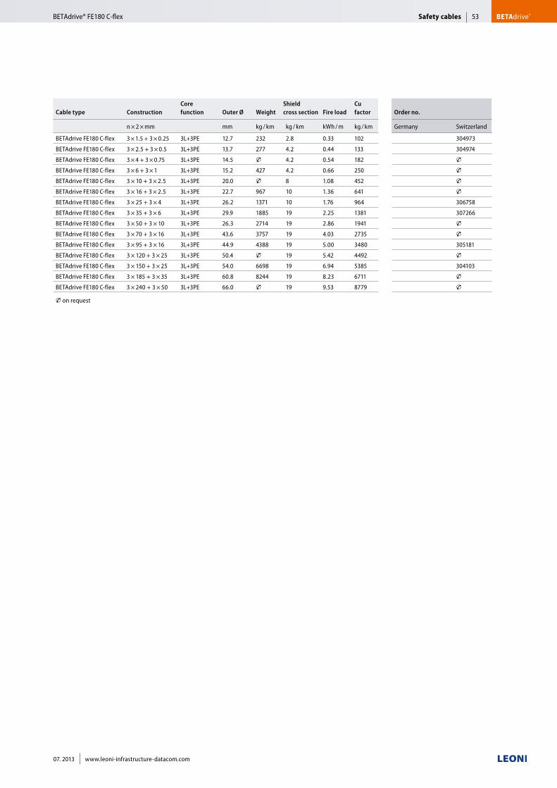
Cable type ConstructionCore function Outer Ø Weight
Shield cross section Fire load
Cu factor Order no.
n × 2 × mm mm kg / km kg / km kWh / m kg / km Germany Switzerland
BETAdrive FE180 C-flex 3 × 1.5 + 3 × 0.25 3L+3PE 12.7 232 2.8 0.33 102 304973
BETAdrive FE180 C-flex 3 × 2.5 + 3 × 0.5 3L+3PE 13.7 277 4.2 0.44 133 304974
BETAdrive FE180 C-flex 3 × 4 + 3 × 0.75 3L+3PE 14.5 T 4.2 0.54 182 TBETAdrive FE180 C-flex 3 × 6 + 3 × 1 3L+3PE 15.2 427 4.2 0.66 250 TBETAdrive FE180 C-flex 3 × 10 + 3 × 2.5 3L+3PE 20.0 T 8 1.08 452 TBETAdrive FE180 C-flex 3 × 16 + 3 × 2.5 3L+3PE 22.7 967 10 1.36 641 TBETAdrive FE180 C-flex 3 × 25 + 3 × 4 3L+3PE 26.2 1371 10 1.76 964 306758
BETAdrive FE180 C-flex 3 × 35 + 3 × 6 3L+3PE 29.9 1885 19 2.25 1381 307266
BETAdrive FE180 C-flex 3 × 50 + 3 × 10 3L+3PE 26.3 2714 19 2.86 1941 TBETAdrive FE180 C-flex 3 × 70 + 3 × 16 3L+3PE 43.6 3757 19 4.03 2735 TBETAdrive FE180 C-flex 3 × 95 + 3 × 16 3L+3PE 44.9 4388 19 5.00 3480 305181
BETAdrive FE180 C-flex 3 × 120 + 3 × 25 3L+3PE 50.4 T 19 5.42 4492 TBETAdrive FE180 C-flex 3 × 150 + 3 × 25 3L+3PE 54.0 6698 19 6.94 5385 304103
BETAdrive FE180 C-flex 3 × 185 + 3 × 35 3L+3PE 60.8 8244 19 8.23 6711 TBETAdrive FE180 C-flex 3 × 240 + 3 × 50 3L+3PE 66.0 T 19 9.53 8779 T
T on request
Safety cables BETAdrive®BETAdrive® FE180 C-flex 53
07. 2013 www.leoni-infrastructure-datacom.com
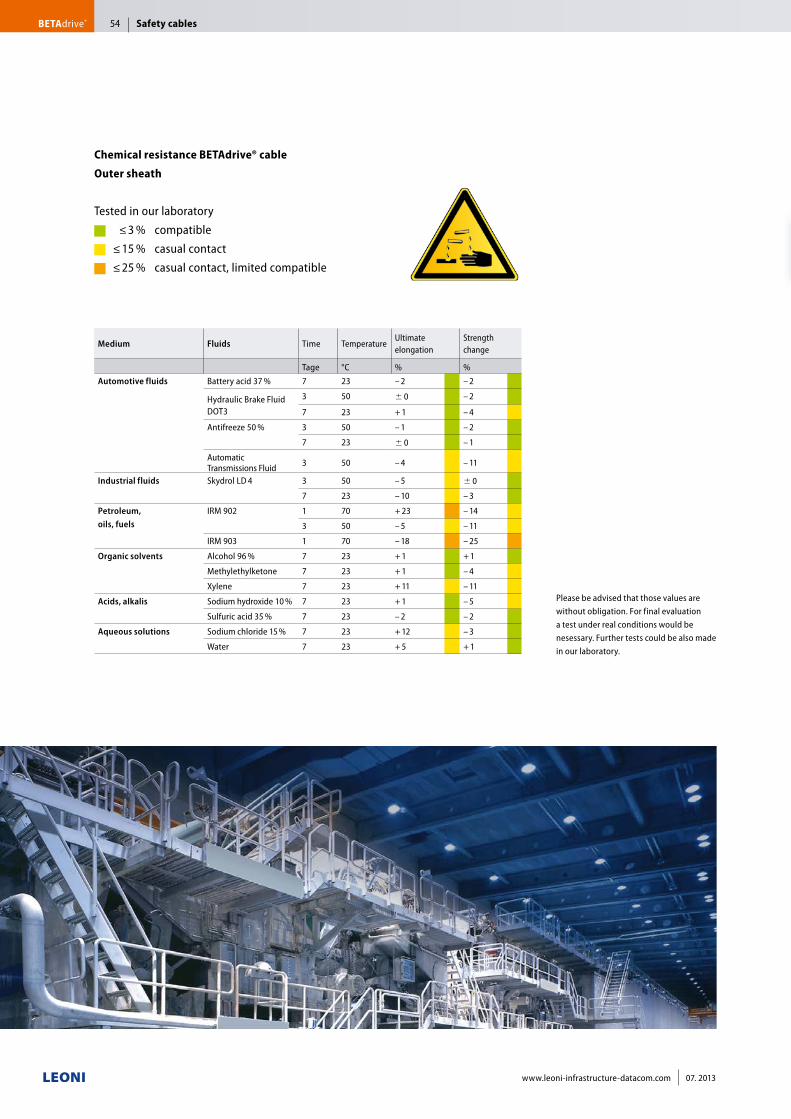
Chemical resistance BETAdrive® cable
Outer sheath
Tested in our laboratory ≤ 3 % compatible ≤ 15 % casual contact ≤ 25 % casual contact, limited compatible
Medium Fluids Time TemperatureUltimate elongation
Strength change
Tage °C % %Automotive fluids Battery acid 37 % 7 23 – 2 – 2
Hydraulic Brake Fluid DOT3
3 50 0 – 2
7 23 + 1 – 4
Antifreeze 50 % 3 50 – 1 – 2
7 23 0 – 1
Automatic Transmissions Fluid 3 50 – 4 – 11
Industrial fluids Skydrol LD 4 3 50 – 5 0
7 23 – 10 – 3
Petroleum, oils, fuels
IRM 902 1 70 + 23 – 14
3 50 – 5 – 11
IRM 903 1 70 – 18 – 25
Organic solvents Alcohol 96 % 7 23 + 1 + 1
Methylethylketone 7 23 + 1 – 4
Xylene 7 23 + 11 – 11
Acids, alkalis Sodium hydroxide 10 % 7 23 + 1 – 5
Sulfuric acid 35 % 7 23 – 2 – 2
Aqueous solutions Sodium chloride 15 % 7 23 + 12 – 3
Water 7 23 + 5 + 1
Please be advised that those values are without obligation. For final evaluation a test under real conditions would be nesessary. Further tests could be also made in our laboratory.
Safety cablesBETAdrive® 54
www.leoni-infrastructure-datacom.com 07. 2013
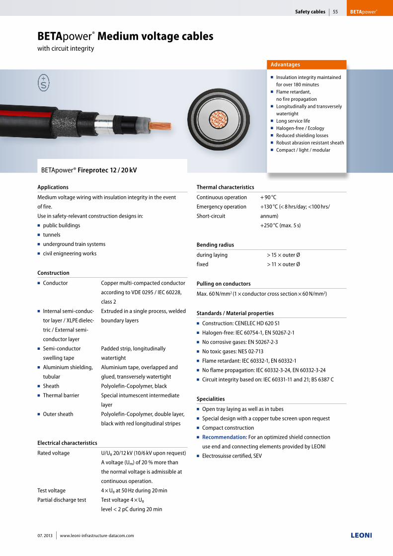
BETApower® Fireprotec 12 / 20 kV
Applications
Medium voltage wiring with insulation integrity in the event
of fire.
Use in safety-relevant construction designs in: ■■ public buildings■■ tunnels■■ underground train systems ■■ civil enigneering works
Construction
■■ Conductor
■■ Internal semi-conduc-
tor layer / XLPE dielec-
tric / External semi-
conductor layer■■ Semi-conductor
swelling tape■■ Aluminium shielding,
tubular■■ Sheath ■■ Thermal barrier
■■ Outer sheath
Copper multi-compacted conductor
according to VDE 0295 / IEC 60228,
class 2
Extruded in a single process, welded
boundary layers
Padded strip, longitudinally
watertight
Aluminium tape, overlapped and
glued, transversely watertight
Polyolefin-Copolymer, black
Special intumescent intermediate
layer
Polyolefin-Copolymer, double layer,
black with red longitudinal stripes
Electrical characteristics
Rated voltage
Test voltage
Partial discharge test
U/U₀ 20/12 kV (10/6 kV upon request)
A voltage (Um) of 20 % more than
the normal voltage is admissible at
continuous operation.
4 × U₀ at 50 Hz during 20 min
Test voltage 4 × U₀
level < 2 pC during 20 min
Thermal characteristics
Continuous operation
Emergency operation
Short-circuit
+ 90 °C
+130 °C (< 8 hrs/day; <100 hrs/
annum)
+250 °C (max. 5 s)
Bending radius
during laying
fixed
> 15 × outer Ø
> 11 × outer Ø
Pulling on conductors
Max. 60 N/mm2 (1 × conductor cross section × 60 N/mm2)
Standards / Material properties
■■ Construction: CENELEC HD 620 S1■■ Halogen-free: IEC 60754-1, EN 50267-2-1■■ No corrosive gases: EN 50267-2-3■■ No toxic gases: NES 02-713■■ Flame retardant: IEC 60332-1, EN 60332-1■■ No flame propagation: IEC 60332-3-24, EN 60332-3-24■■ Circuit integrity based on: IEC 60331-11 and 21; BS 6387 C
Specialities
■■ Open tray laying as well as in tubes■■ Special design with a copper tube screen upon request■■ Compact construction■■ Recommendation: For an optimized shield connection
use end and connecting elements provided by LEONI ■■ Electrosuisse certified, SEV
Advantages
■■ Insulation integrity maintained for over 180 minutes
■■ Flame retardant, no fire propagation
■■ Longitudinally and transversely watertight
■■ Long service life■■ Halogen-free / Ecology ■■ Reduced shielding losses■■ Robust abrasion resistant sheath■■ Compact / light / modular
BETApower® Medium voltage cables with circuit integrity
Safety cables BETApower®55
07. 2013 www.leoni-infrastructure-datacom.com
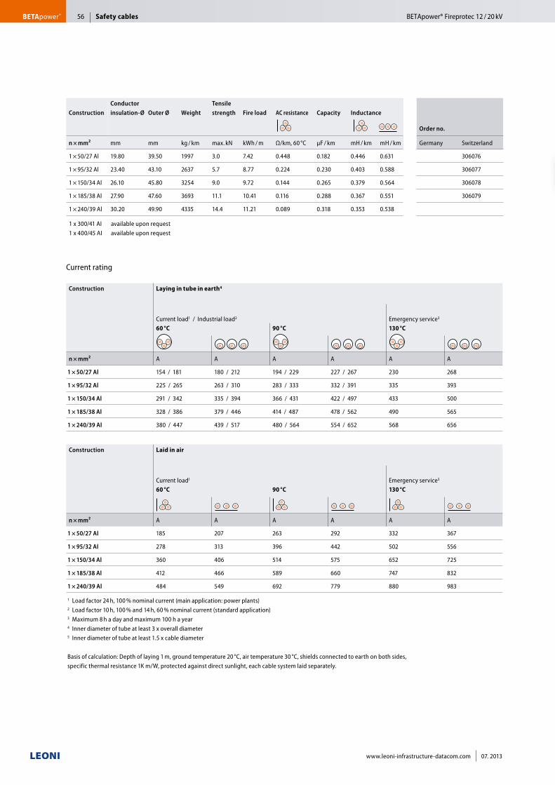
Safety cablesBETApower®
ConstructionConductor insulation-Ø Outer Ø Weight
Tensile strength Fire load AC resistance Capacity Inductance
Order no.
n × mm² mm mm kg / km max. kN kWh / m Ω/km, 60 °C μF / km mH / km mH / km Germany Switzerland
1 × 50/27 Al 19.80 39.50 1997 3.0 7.42 0.448 0.182 0.446 0.631 306076
1 × 95/32 Al 23.40 43.10 2637 5.7 8.77 0.224 0.230 0.403 0.588 306077
1 × 150/34 Al 26.10 45.80 3254 9.0 9.72 0.144 0.265 0.379 0.564 306078
1 × 185/38 Al 27.90 47.60 3693 11.1 10.41 0.116 0.288 0.367 0.551 306079
1 × 240/39 Al 30.20 49.90 4335 14.4 11.21 0.089 0.318 0.353 0.538
1 x 300/41 AI available upon request 1 x 400/45 AI available upon request
Construction Laying in tube in earth4
Current load1 / Industrial load2 Emergency service3
60 °C 90 °C 130 °C
n × mm² A A A A A A
1 × 50/27 Al 154 / 181 180 / 212 194 / 229 227 / 267 230 268
1 × 95/32 Al 225 / 265 263 / 310 283 / 333 332 / 391 335 393
1 × 150/34 Al 291 / 342 335 / 394 366 / 431 422 / 497 433 500
1 × 185/38 Al 328 / 386 379 / 446 414 / 487 478 / 562 490 565
1 × 240/39 Al 380 / 447 439 / 517 480 / 564 554 / 652 568 656
Construction Laid in air
Current load1 Emergency service3
60 °C 90 °C 130 °C
n × mm² A A A A A A
1 × 50/27 Al 185 207 263 292 332 367
1 × 95/32 Al 278 313 396 442 502 556
1 × 150/34 Al 360 406 514 575 652 725
1 × 185/38 Al 412 466 589 660 747 832
1 × 240/39 Al 484 549 692 779 880 983
1 Load factor 24 h, 100 % nominal current (main application: power plants)2 Load factor 10 h, 100 % and 14 h, 60 % nominal current (standard application)3 Maximum 8 h a day and maximum 100 h a year4 Inner diameter of tube at least 3 x overall diameter5 Inner diameter of tube at least 1.5 x cable diameter
Basis of calculation: Depth of laying 1 m, ground temperature 20 °C, air temperature 30 °C, shields connected to earth on both sides, specific thermal resistance 1K m/W, protected against direct sunlight, each cable system laid separately.
Current rating
BETApower® Fireprotec 12 / 20 kV56
www.leoni-infrastructure-datacom.com 07. 2013
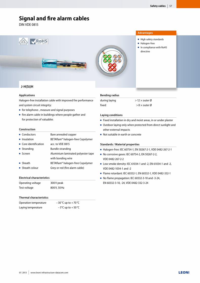
J-H(St)H
Applications
Halogen-free installation cable with improved fire performance
and system circuit integrity: ■■ for telephone-, measure and signal purposes■■ fire alarm cable in buildings where people gather and
for protection of valuables
Construction
■■ Conductors■■ Insulation■■ Core identification■■ Stranding■■ Screen
■■ Sheath■■ Sheath colour
Bare annealed copper
BETAflam® halogen-free Copolymer
acc. to VDE 0815
Bundle stranding
Aluminium laminated polyester tape
with bonding wire
BETAflam® halogen-free Copolymer
Grey or red (fire alarm cable)
Electrical characteristics
Operating voltage
Test voltage
300 V peak
800 V, 50 Hz
Thermal characteristics
Operation temperature
Laying temperature
– 40– 30 °C up to + 70 °C
– 40– 5°C up to + 50 °C
Bending radius
during laying
fixed
> 12 × outer Ø
> 8 × outer Ø
Laying conditions
■■ Fixed installation in dry and moist areas, in or under plaster■■ Outdoor laying only when protected from direct sunlight and
other external impacts■■ Not suitable in earth or concrete
Standards / Material properties
■■ Halogen-free: IEC 60754-1, EN 50267-2-1, VDE 0482-267-2-1■■ No corrosive gases: IEC 60754-2, EN 50267-2-2,
VDE 0482-267-2-2■■ Low smoke density: IEC 61034-1 and -2, EN 61034-1 and -2,
VDE 0482-1034-1 and -2■■ Flame retardant: IEC 60332-1, EN 60332-1, VDE 0482-332-1 ■■ No flame propagation: IEC 60332-3-10 and -3-24,
EN 60332-3-10, -24, VDE 0482-332-3-24
Advantages
■■ High safety standards■■ Halogen-free■■ In compliance with RoHS
directive
Signal and fire alarm cables DIN VDE 0815
Safety cables 57
07. 2013 www.leoni-infrastructure-datacom.com
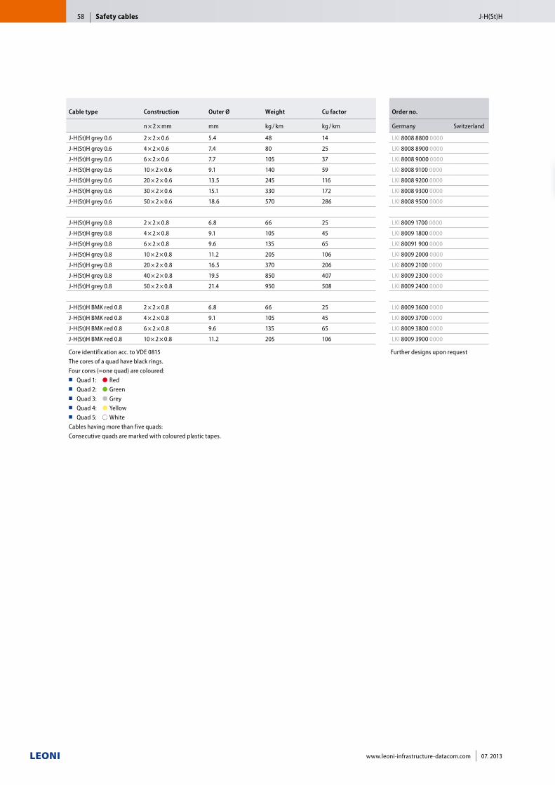
Cable type Construction Outer Ø Weight Cu factor Order no.
n × 2 × mm mm kg / km kg / km Germany Switzerland
J-H(St)H grey 0.6 2 × 2 × 0.6 5.4 48 14 LKI 8008 8800 0000
J-H(St)H grey 0.6 4 × 2 × 0.6 7.4 80 25 LKI 8008 8900 0000
J-H(St)H grey 0.6 6 × 2 × 0.6 7.7 105 37 LKI 8008 9000 0000
J-H(St)H grey 0.6 10 × 2 × 0.6 9.1 140 59 LKI 8008 9100 0000
J-H(St)H grey 0.6 20 × 2 × 0.6 13.5 245 116 LKI 8008 9200 0000
J-H(St)H grey 0.6 30 × 2 × 0.6 15.1 330 172 LKI 8008 9300 0000
J-H(St)H grey 0.6 50 × 2 × 0.6 18.6 570 286 LKI 8008 9500 0000
J-H(St)H grey 0.8 2 × 2 × 0.8 6.8 66 25 LKI 8009 1700 0000
J-H(St)H grey 0.8 4 × 2 × 0.8 9.1 105 45 LKI 8009 1800 0000
J-H(St)H grey 0.8 6 × 2 × 0.8 9.6 135 65 LKI 80091 900 0000
J-H(St)H grey 0.8 10 × 2 × 0.8 11.2 205 106 LKI 8009 2000 0000
J-H(St)H grey 0.8 20 × 2 × 0.8 16.5 370 206 LKI 8009 2100 0000
J-H(St)H grey 0.8 40 × 2 × 0.8 19.5 850 407 LKI 8009 2300 0000
J-H(St)H grey 0.8 50 × 2 × 0.8 21.4 950 508 LKI 8009 2400 0000
J-H(St)H BMK red 0.8 2 × 2 × 0.8 6.8 66 25 LKI 8009 3600 0000
J-H(St)H BMK red 0.8 4 × 2 × 0.8 9.1 105 45 LKI 8009 3700 0000
J-H(St)H BMK red 0.8 6 × 2 × 0.8 9.6 135 65 LKI 8009 3800 0000
J-H(St)H BMK red 0.8 10 × 2 × 0.8 11.2 205 106 LKI 8009 3900 0000
Core identification acc. to VDE 0815The cores of a quad have black rings.Four cores (=one quad) are coloured:■■ Quad 1: ●■Red■■ Quad 2: ●■Green■■ Quad 3: ●■Grey■■ Quad 4: ●■Yellow■■ Quad 5: ●■White
Cables having more than five quads:Consecutive quads are marked with coloured plastic tapes.
Further designs upon request
Safety cables J-H(St)H58
www.leoni-infrastructure-datacom.com 07. 2013
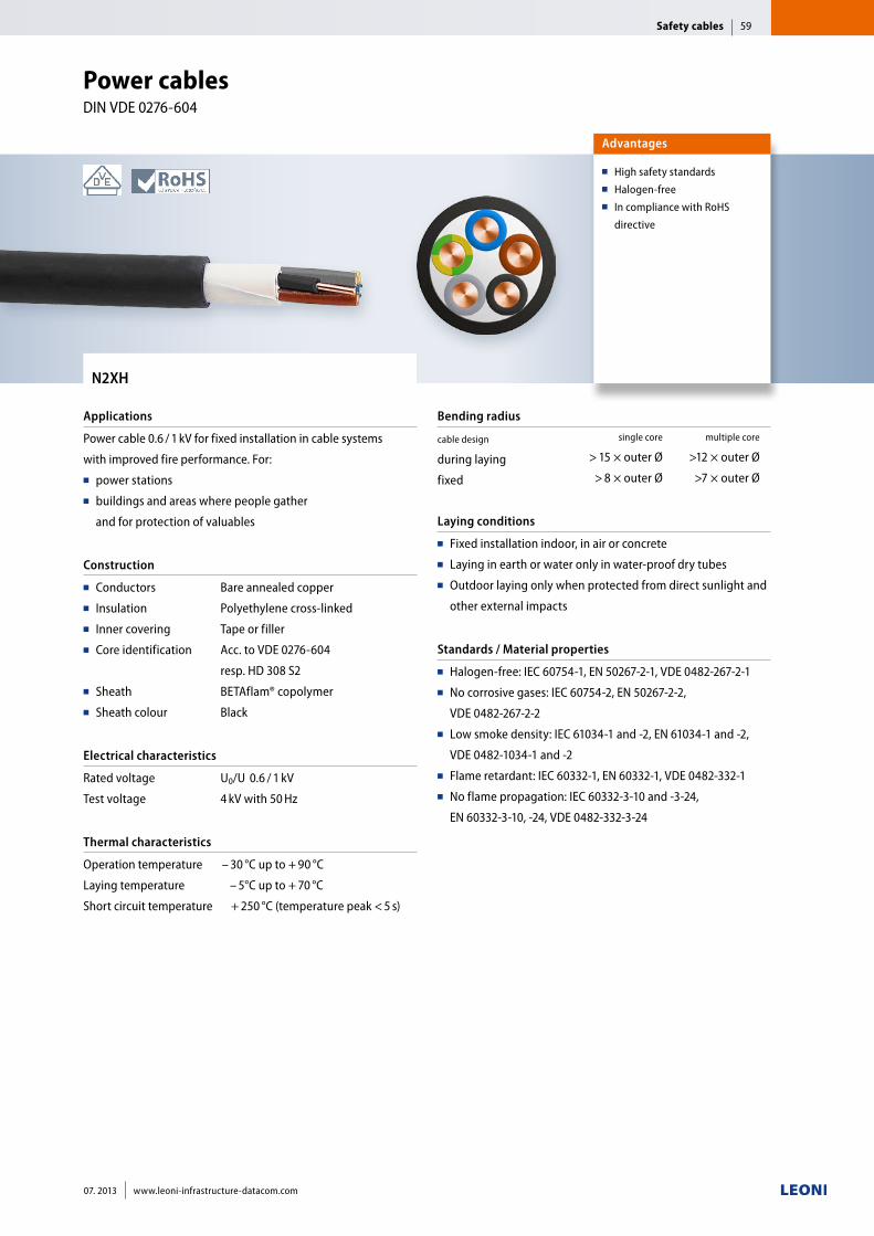
N2XH
Applications
Power cable 0.6 / 1 kV for fixed installation in cable systems
with improved fire performance. For:■■ power stations■■ buildings and areas where people gather
and for protection of valuables
Construction
■■ Conductors■■ Insulation■■ Inner covering■■ Core identification
■■ Sheath■■ Sheath colour
Bare annealed copper
Polyethylene cross-linked
Tape or filler
Acc. to VDE 0276-604
resp. HD 308 S2
BETAflam® copolymer
Black
Electrical characteristics
Rated voltage
Test voltage
U0/U 0.6 / 1 kV
4 kV with 50 Hz
Thermal characteristics
Operation temperature
Laying temperature
Short circuit temperature
– 30 °C up to + 90 °C
– 5°C up to + 70 °C
+ 250 °C (temperature peak < 5 s)
Bending radius
cable design
during laying
fixed
single core multiple core
> 15 × outer Ø >12 × outer Ø
> 8 × outer Ø >7 × outer Ø
Laying conditions
■■ Fixed installation indoor, in air or concrete ■■ Laying in earth or water only in water-proof dry tubes■■ Outdoor laying only when protected from direct sunlight and
other external impacts
Standards / Material properties
■■ Halogen-free: IEC 60754-1, EN 50267-2-1, VDE 0482-267-2-1■■ No corrosive gases: IEC 60754-2, EN 50267-2-2,
VDE 0482-267-2-2■■ Low smoke density: IEC 61034-1 and -2, EN 61034-1 and -2,
VDE 0482-1034-1 and -2■■ Flame retardant: IEC 60332-1, EN 60332-1, VDE 0482-332-1■■ No flame propagation: IEC 60332-3-10 and -3-24,
EN 60332-3-10, -24, VDE 0482-332-3-24
Advantages
■■ High safety standards■■ Halogen-free■■ In compliance with RoHS
directive
Power cables DIN VDE 0276-604
Safety cables 59
07. 2013 www.leoni-infrastructure-datacom.com
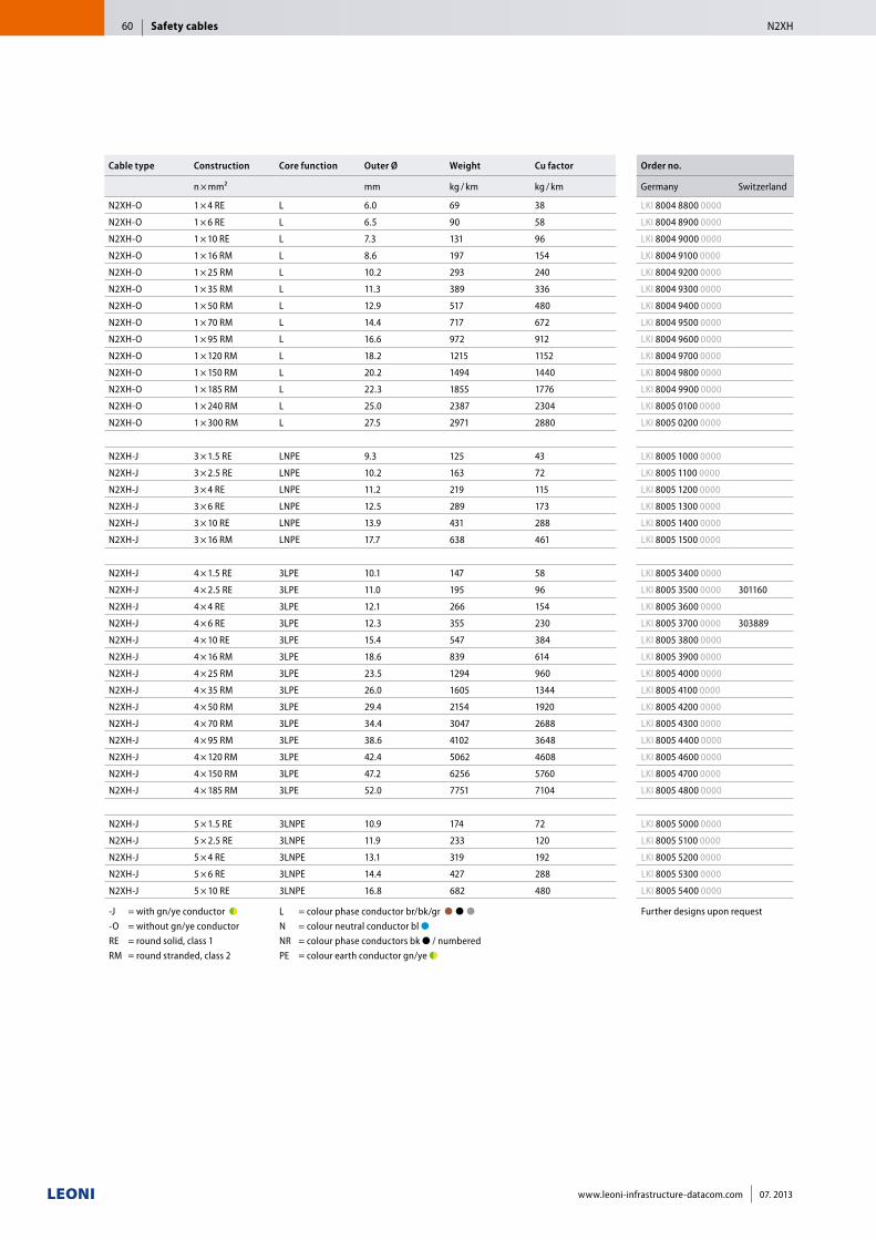
Cable type Construction Core function Outer Ø Weight Cu factor Order no.
n × mm² mm kg / km kg / km Germany Switzerland
N2XH-O 1 × 4 RE L 6.0 69 38 LKI 8004 8800 0000
N2XH-O 1 × 6 RE L 6.5 90 58 LKI 8004 8900 0000
N2XH-O 1 × 10 RE L 7.3 131 96 LKI 8004 9000 0000
N2XH-O 1 × 16 RM L 8.6 197 154 LKI 8004 9100 0000
N2XH-O 1 × 25 RM L 10.2 293 240 LKI 8004 9200 0000
N2XH-O 1 × 35 RM L 11.3 389 336 LKI 8004 9300 0000
N2XH-O 1 × 50 RM L 12.9 517 480 LKI 8004 9400 0000
N2XH-O 1 × 70 RM L 14.4 717 672 LKI 8004 9500 0000
N2XH-O 1 × 95 RM L 16.6 972 912 LKI 8004 9600 0000
N2XH-O 1 × 120 RM L 18.2 1215 1152 LKI 8004 9700 0000
N2XH-O 1 × 150 RM L 20.2 1494 1440 LKI 8004 9800 0000
N2XH-O 1 × 185 RM L 22.3 1855 1776 LKI 8004 9900 0000
N2XH-O 1 × 240 RM L 25.0 2387 2304 LKI 8005 0100 0000
N2XH-O 1 × 300 RM L 27.5 2971 2880 LKI 8005 0200 0000
N2XH-J 3 × 1.5 RE LNPE 9.3 125 43 LKI 8005 1000 0000
N2XH-J 3 × 2.5 RE LNPE 10.2 163 72 LKI 8005 1100 0000
N2XH-J 3 × 4 RE LNPE 11.2 219 115 LKI 8005 1200 0000
N2XH-J 3 × 6 RE LNPE 12.5 289 173 LKI 8005 1300 0000
N2XH-J 3 × 10 RE LNPE 13.9 431 288 LKI 8005 1400 0000
N2XH-J 3 × 16 RM LNPE 17.7 638 461 LKI 8005 1500 0000
N2XH-J 4 × 1.5 RE 3LPE 10.1 147 58 LKI 8005 3400 0000
N2XH-J 4 × 2.5 RE 3LPE 11.0 195 96 LKI 8005 3500 0000 301160
N2XH-J 4 × 4 RE 3LPE 12.1 266 154 LKI 8005 3600 0000
N2XH-J 4 × 6 RE 3LPE 12.3 355 230 LKI 8005 3700 0000 303889
N2XH-J 4 × 10 RE 3LPE 15.4 547 384 LKI 8005 3800 0000
N2XH-J 4 × 16 RM 3LPE 18.6 839 614 LKI 8005 3900 0000
N2XH-J 4 × 25 RM 3LPE 23.5 1294 960 LKI 8005 4000 0000
N2XH-J 4 × 35 RM 3LPE 26.0 1605 1344 LKI 8005 4100 0000
N2XH-J 4 × 50 RM 3LPE 29.4 2154 1920 LKI 8005 4200 0000
N2XH-J 4 × 70 RM 3LPE 34.4 3047 2688 LKI 8005 4300 0000
N2XH-J 4 × 95 RM 3LPE 38.6 4102 3648 LKI 8005 4400 0000
N2XH-J 4 × 120 RM 3LPE 42.4 5062 4608 LKI 8005 4600 0000
N2XH-J 4 × 150 RM 3LPE 47.2 6256 5760 LKI 8005 4700 0000
N2XH-J 4 × 185 RM 3LPE 52.0 7751 7104 LKI 8005 4800 0000
N2XH-J 5 × 1.5 RE 3LNPE 10.9 174 72 LKI 8005 5000 0000
N2XH-J 5 × 2.5 RE 3LNPE 11.9 233 120 LKI 8005 5100 0000
N2XH-J 5 × 4 RE 3LNPE 13.1 319 192 LKI 8005 5200 0000
N2XH-J 5 × 6 RE 3LNPE 14.4 427 288 LKI 8005 5300 0000
N2XH-J 5 × 10 RE 3LNPE 16.8 682 480 LKI 8005 5400 0000
-J = with gn/ye conductor ●◗ ■■ -O = without gn/ye conductor ■ RE = round solid, class 1 RM = round stranded, class 2
L = colour phase conductor br/bk/gr ●■●■●■■ N = colour neutral conductor bl ●■■ NR = colour phase conductors bk ● / numbered PE = colour earth conductor gn/ye ●◗
Further designs upon request
Safety cables N2XH60
www.leoni-infrastructure-datacom.com 07. 2013
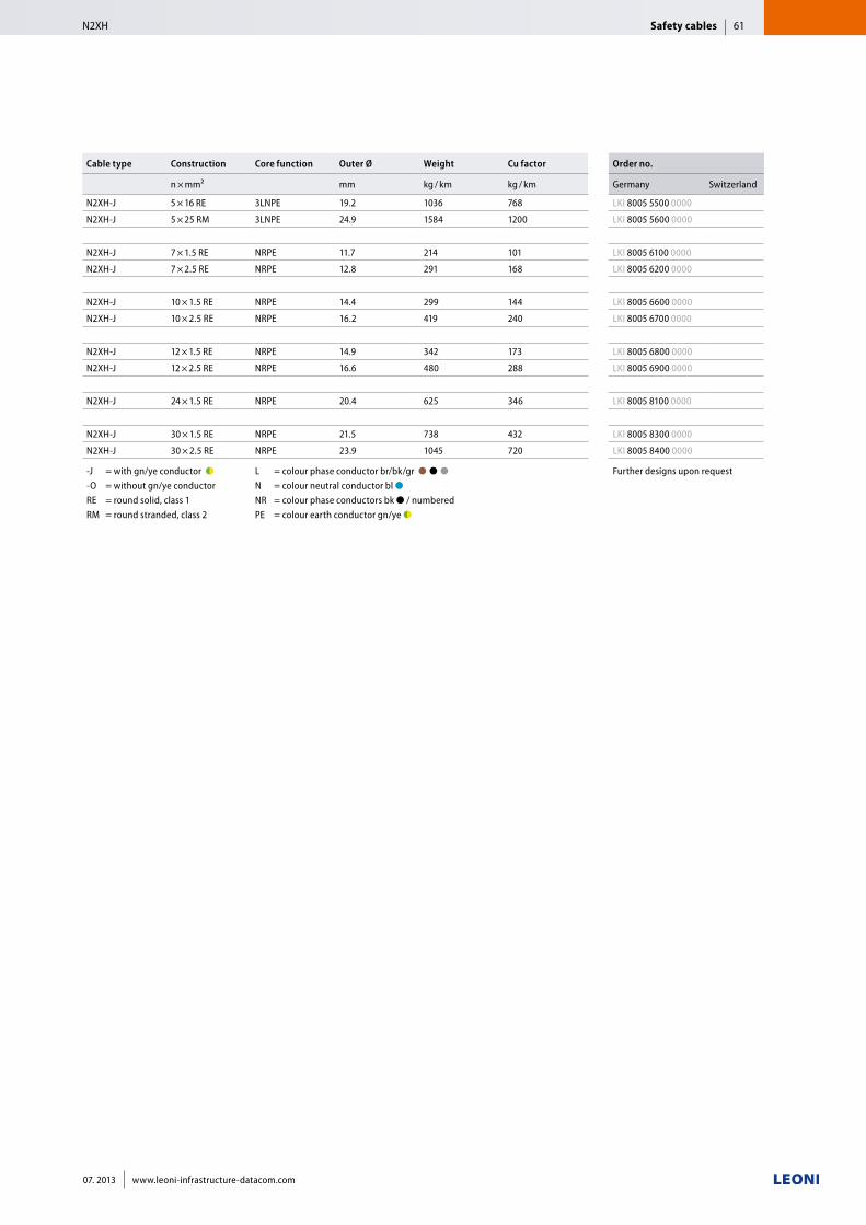
Cable type Construction Core function Outer Ø Weight Cu factor Order no.
n × mm² mm kg / km kg / km Germany Switzerland
N2XH-J 5 × 16 RE 3LNPE 19.2 1036 768 LKI 8005 5500 0000
N2XH-J 5 × 25 RM 3LNPE 24.9 1584 1200 LKI 8005 5600 0000
N2XH-J 7 × 1.5 RE NRPE 11.7 214 101 LKI 8005 6100 0000
N2XH-J 7 × 2.5 RE NRPE 12.8 291 168 LKI 8005 6200 0000
N2XH-J 10 × 1.5 RE NRPE 14.4 299 144 LKI 8005 6600 0000
N2XH-J 10 × 2.5 RE NRPE 16.2 419 240 LKI 8005 6700 0000
N2XH-J 12 × 1.5 RE NRPE 14.9 342 173 LKI 8005 6800 0000
N2XH-J 12 × 2.5 RE NRPE 16.6 480 288 LKI 8005 6900 0000
N2XH-J 24 × 1.5 RE NRPE 20.4 625 346 LKI 8005 8100 0000
N2XH-J 30 × 1.5 RE NRPE 21.5 738 432 LKI 8005 8300 0000
N2XH-J 30 × 2.5 RE NRPE 23.9 1045 720 LKI 8005 8400 0000
-J = with gn/ye conductor ●◗ ■■ -O = without gn/ye conductor ■ RE = round solid, class 1 RM = round stranded, class 2
L = colour phase conductor br/bk/gr ●■●■●■■ N = colour neutral conductor bl ●■■ NR = colour phase conductors bk ● / numbered PE = colour earth conductor gn/ye ●◗
Further designs upon request
Safety cablesN2XH 61
07. 2013 www.leoni-infrastructure-datacom.com
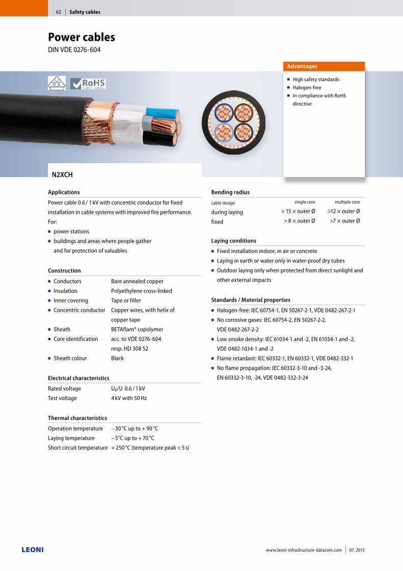
N2XCH
Applications
Power cable 0.6 / 1 kV with concentric conductor for fixed
installation in cable systems with improved fire performance.
For:■■ power stations■■ buildings and areas where people gather
and for protection of valuables
Construction
■■ Conductors■■ Insulation■■ Inner covering■■ Concentric conductor
■■ Sheath■■ Core identification
■■ Sheath colour
Bare annealed copper
Polyethylene cross-linked
Tape or filler
Copper wires, with helix of
copper tape
BETAflam® copolymer
acc. to VDE 0276-604
resp. HD 308 S2
Black
Electrical characteristics
Rated voltage
Test voltage
U0/U 0.6 / 1 kV
4 kV with 50 Hz
Thermal characteristics
Operation temperature
Laying temperature
Short circuit temperature
– 30 °C up to + 90 °C
– 5°C up to + 70 °C
+ 250 °C (temperature peak < 5 s)
Bending radius
cable design
during laying
fixed
single core multiple core
> 15 × outer Ø >12 × outer Ø
> 8 × outer Ø >7 × outer Ø
Laying conditions
■■ Fixed installation indoor, in air or concrete ■■ Laying in earth or water only in water-proof dry tubes■■ Outdoor laying only when protected from direct sunlight and
other external impacts
Standards / Material properties
■■ Halogen-free: IEC 60754-1, EN 50267-2-1, VDE 0482-267-2-1■■ No corrosive gases: IEC 60754-2, EN 50267-2-2,
VDE 0482-267-2-2■■ Low smoke density: IEC 61034-1 and -2, EN 61034-1 and -2,
VDE 0482-1034-1 and -2■■ Flame retardant: IEC 60332-1, EN 60332-1, VDE 0482-332-1■■ No flame propagation: IEC 60332-3-10 and -3-24,
EN 60332-3-10, -24, VDE 0482-332-3-24
Advantages
■■ High safety standards■■ Halogen-free■■ In compliance with RoHS
directive
Power cables DIN VDE 0276-604
Safety cables62
www.leoni-infrastructure-datacom.com 07. 2013
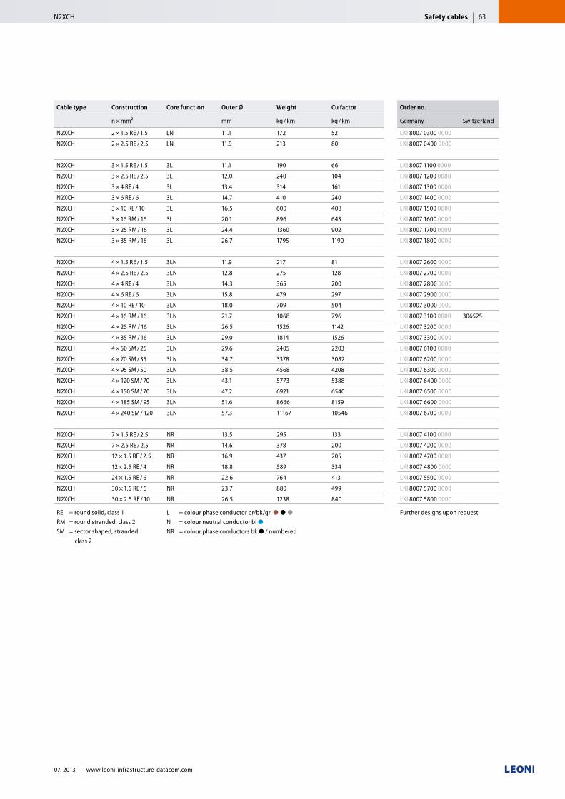
Cable type Construction Core function Outer Ø Weight Cu factor Order no.
n × mm² mm kg / km kg / km Germany Switzerland
N2XCH 2 × 1.5 RE / 1.5 LN 11.1 172 52 LKI 8007 0300 0000
N2XCH 2 × 2.5 RE / 2.5 LN 11.9 213 80 LKI 8007 0400 0000
N2XCH 3 × 1.5 RE / 1.5 3L 11.1 190 66 LKI 8007 1100 0000
N2XCH 3 × 2.5 RE / 2.5 3L 12.0 240 104 LKI 8007 1200 0000
N2XCH 3 × 4 RE / 4 3L 13.4 314 161 LKI 8007 1300 0000
N2XCH 3 × 6 RE / 6 3L 14.7 410 240 LKI 8007 1400 0000
N2XCH 3 × 10 RE / 10 3L 16.5 600 408 LKI 8007 1500 0000
N2XCH 3 × 16 RM / 16 3L 20.1 896 643 LKI 8007 1600 0000
N2XCH 3 × 25 RM / 16 3L 24.4 1360 902 LKI 8007 1700 0000
N2XCH 3 × 35 RM / 16 3L 26.7 1795 1190 LKI 8007 1800 0000
N2XCH 4 × 1.5 RE / 1.5 3LN 11.9 217 81 LKI 8007 2600 0000
N2XCH 4 × 2.5 RE / 2.5 3LN 12.8 275 128 LKI 8007 2700 0000
N2XCH 4 × 4 RE / 4 3LN 14.3 365 200 LKI 8007 2800 0000
N2XCH 4 × 6 RE / 6 3LN 15.8 479 297 LKI 8007 2900 0000
N2XCH 4 × 10 RE / 10 3LN 18.0 709 504 LKI 8007 3000 0000
N2XCH 4 × 16 RM / 16 3LN 21.7 1068 796 LKI 8007 3100 0000 306525
N2XCH 4 × 25 RM / 16 3LN 26.5 1526 1142 LKI 8007 3200 0000
N2XCH 4 × 35 RM / 16 3LN 29.0 1814 1526 LKI 8007 3300 0000
N2XCH 4 × 50 SM / 25 3LN 29.6 2405 2203 LKI 8007 6100 0000
N2XCH 4 × 70 SM / 35 3LN 34.7 3378 3082 LKI 8007 6200 0000
N2XCH 4 × 95 SM / 50 3LN 38.5 4568 4208 LKI 8007 6300 0000
N2XCH 4 × 120 SM / 70 3LN 43.1 5773 5388 LKI 8007 6400 0000
N2XCH 4 × 150 SM / 70 3LN 47.2 6921 6540 LKI 8007 6500 0000
N2XCH 4 × 185 SM / 95 3LN 51.6 8666 8159 LKI 8007 6600 0000
N2XCH 4 × 240 SM / 120 3LN 57.3 11167 10546 LKI 8007 6700 0000
N2XCH 7 × 1.5 RE / 2.5 NR 13.5 295 133 LKI 8007 4100 0000
N2XCH 7 × 2.5 RE / 2.5 NR 14.6 378 200 LKI 8007 4200 0000
N2XCH 12 × 1.5 RE / 2.5 NR 16.9 437 205 LKI 8007 4700 0000
N2XCH 12 × 2.5 RE / 4 NR 18.8 589 334 LKI 8007 4800 0000
N2XCH 24 × 1.5 RE / 6 NR 22.6 764 413 LKI 8007 5500 0000
N2XCH 30 × 1.5 RE / 6 NR 23.7 880 499 LKI 8007 5700 0000
N2XCH 30 × 2.5 RE / 10 NR 26.5 1238 840 LKI 8007 5800 0000
RE = round solid, class 1 RM = round stranded, class 2SM = sector shaped, stranded class 2
L = colour phase conductor br/bk/gr ●■●■●■■ N = colour neutral conductor bl ●■■ NR = colour phase conductors bk ● / numbered
Further designs upon request
Safety cablesN2XCH 63
07. 2013 www.leoni-infrastructure-datacom.com
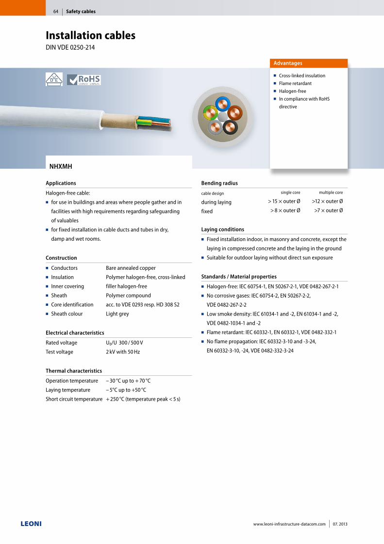
NHXMH
Applications
Halogen-free cable:■■ for use in buildings and areas where people gather and in
facilities with high requirements regarding safeguarding
of valuables■■ for fixed installation in cable ducts and tubes in dry,
damp and wet rooms.
Construction
■■ Conductors■■ Insulation■■ Inner covering■■ Sheath■■ Core identification■■ Sheath colour
Bare annealed copper
Polymer halogen-free, cross-linked
filler halogen-free
Polymer compound
acc. to VDE 0293 resp. HD 308 S2
Light grey
Electrical characteristics
Rated voltage
Test voltage
U0/U 300 / 500 V
2 kV with 50 Hz
Thermal characteristics
Operation temperature
Laying temperature
Short circuit temperature
– 30 °C up to + 70 °C
– 5°C up to +50 °C
+ 250 °C (temperature peak < 5 s)
Bending radius
cable design
during laying
fixed
single core multiple core
> 15 × outer Ø >12 × outer Ø
> 8 × outer Ø >7 × outer Ø
Laying conditions
■■ Fixed installation indoor, in masonry and concrete, except the
laying in compressed concrete and the laying in the ground■■ Suitable for outdoor laying without direct sun exposure
Standards / Material properties
■■ Halogen-free: IEC 60754-1, EN 50267-2-1, VDE 0482-267-2-1■■ No corrosive gases: IEC 60754-2, EN 50267-2-2,
VDE 0482-267-2-2■■ Low smoke density: IEC 61034-1 and -2, EN 61034-1 and -2,
VDE 0482-1034-1 and -2■■ Flame retardant: IEC 60332-1, EN 60332-1, VDE 0482-332-1■■ No flame propagation: IEC 60332-3-10 and -3-24,
EN 60332-3-10, -24, VDE 0482-332-3-24
Advantages
■■ Cross-linked insulation■■ Flame retardant■■ Halogen-free■■ In compliance with RoHS
directive
Installation cables DIN VDE 0250-214
Safety cables64
www.leoni-infrastructure-datacom.com 07. 2013
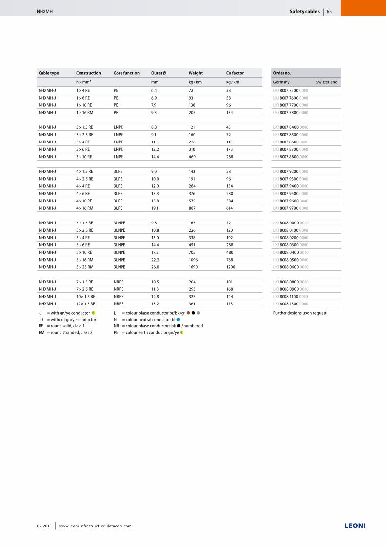
Cable type Construction Core function Outer Ø Weight Cu factor Order no.
n × mm² mm kg / km kg / km Germany Switzerland
NHXMH-J 1 × 4 RE PE 6.4 72 38 LKI 8007 7500 0000
NHXMH-J 1 × 6 RE PE 6.9 93 58 LKI 8007 7600 0000
NHXMH-J 1 × 10 RE PE 7.9 138 96 LKI 8007 7700 0000
NHXMH-J 1 × 16 RM PE 9.3 205 154 LKI 8007 7800 0000
NHXMH-J 3 × 1.5 RE LNPE 8.3 121 43 LKI 8007 8400 0000
NHXMH-J 3 × 2.5 RE LNPE 9.1 160 72 LKI 8007 8500 0000
NHXMH-J 3 × 4 RE LNPE 11.3 226 115 LKI 8007 8600 0000
NHXMH-J 3 × 6 RE LNPE 12.2 310 173 LKI 8007 8700 0000
NHXMH-J 3 × 10 RE LNPE 14.4 469 288 LKI 8007 8800 0000
NHXMH-J 4 × 1.5 RE 3LPE 9.0 143 58 LKI 8007 9200 0000
NHXMH-J 4 × 2.5 RE 3LPE 10.0 191 96 LKI 8007 9300 0000
NHXMH-J 4 × 4 RE 3LPE 12.0 284 154 LKI 8007 9400 0000
NHXMH-J 4 × 6 RE 3LPE 13.3 376 230 LKI 8007 9500 0000
NHXMH-J 4 × 10 RE 3LPE 15.8 575 384 LKI 8007 9600 0000
NHXMH-J 4 × 16 RM 3LPE 19.1 887 614 LKI 8007 9700 0000
NHXMH-J 5 × 1.5 RE 3LNPE 9.8 167 72 LKI 8008 0000 0000
NHXMH-J 5 × 2.5 RE 3LNPE 10.8 226 120 LKI 8008 0100 0000
NHXMH-J 5 × 4 RE 3LNPE 13.0 338 192 LKI 8008 0200 0000
NHXMH-J 5 × 6 RE 3LNPE 14.4 451 288 LKI 8008 0300 0000
NHXMH-J 5 × 10 RE 3LNPE 17.2 705 480 LKI 8008 0400 0000
NHXMH-J 5 × 16 RM 3LNPE 22.2 1096 768 LKI 8008 0500 0000
NHXMH-J 5 × 25 RM 3LNPE 26.0 1690 1200 LKI 8008 0600 0000
NHXMH-J 7 × 1.5 RE NRPE 10.5 204 101 LKI 8008 0800 0000
NHXMH-J 7 × 2.5 RE NRPE 11.8 293 168 LKI 8008 0900 0000
NHXMH-J 10 × 1.5 RE NRPE 12.8 325 144 LKI 8008 1100 0000
NHXMH-J 12 × 1.5 RE NRPE 13.2 361 173 LKI 8008 1300 0000
-J = with gn/ye conductor ●◗ ■■ -O = without gn/ye conductor■ RE = round solid, class 1 RM = round stranded, class 2
L = colour phase conductor br/bk/gr ●■●■●■■ N = colour neutral conductor bl ●■■ NR = colour phase conductors bk ● / numbered PE = colour earth conductor gn/ye ●◗
Further designs upon request
Safety cablesNHXMH 65
07. 2013 www.leoni-infrastructure-datacom.com
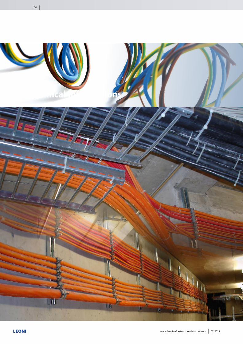
Technical informations
66
www.leoni-infrastructure-datacom.com 07. 2013
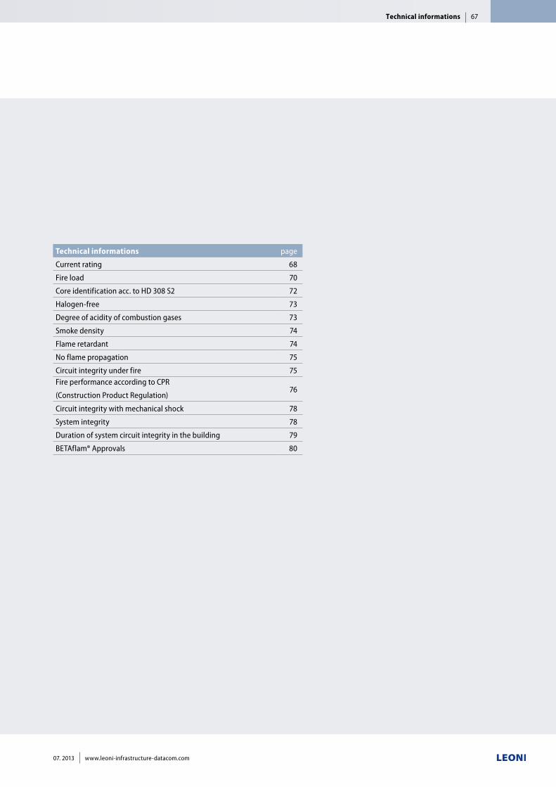
Technical informations page
Current rating 68
Fire load 70
Core identification acc. to HD 308 S2 72
Halogen-free 73
Degree of acidity of combustion gases 73
Smoke density 74
Flame retardant 74
No flame propagation 75
Circuit integrity under fire 75Fire performance according to CPR
(Construction Product Regulation)76
Circuit integrity with mechanical shock 78
System integrity 78
Duration of system circuit integrity in the building 79
BETAflam® Approvals 80
Technical informations 67
07. 2013 www.leoni-infrastructure-datacom.com
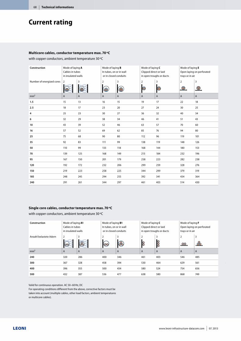
Construction Mode of laying A Cables in tubes in insulated walls
Mode of laying B In tubes, on or in wall or in closed conduits
Mode of laying C Clipped direct or laid in open troughs or ducts
Mode of laying E Open laying on perforated trays or in air
Number of energized cores 2 3 2 3 2 3 2 3
mm² A A A A A A A A
1.5 15 13 16 15 19 17 22 18
2.5 18 17 23 20 27 24 30 25
4 25 23 30 27 36 32 40 34
6 32 29 38 34 46 41 51 43
10 43 39 52 46 63 57 70 60
16 57 52 69 62 85 76 94 80
25 75 68 90 80 112 96 119 101
35 92 83 111 99 138 119 148 126
50 110 99 133 118 168 144 180 153
70 139 125 168 149 213 184 232 196
95 167 150 201 179 258 223 282 238
120 192 172 232 206 299 259 328 276
150 219 223 258 225 344 299 379 319
185 248 245 294 255 392 341 434 364
240 291 261 344 297 461 403 514 430
Valid for continuous operation. AC 50–60 Hz, DCFor operating conditions different from the above, corrective factors must be taken into account (multiple cables, other load factors, ambient temperatures or multicore cables).
Multicore cables, conductor temperature max. 70 ºC
with copper conductors, ambient temperature 30 ºC
Single core cables, conductor temperature max. 70 ºC
with copper conductors, ambient temperature 30 ºC
Construction Mode of laying A1 Cables in tubes in insulated walls
Mode of laying B1 In tubes, on or in wall or in closed conduits
Mode of laying C Clipped direct or laid in open troughs or ducts
Mode of laying F Open laying on perforated trays or in air
Anzahl belastete Adern 2 3 2 3 2 3 2 3
mm² A A A A A A A A
240 320 286 400 346 461 403 546 485
300 367 328 458 394 530 464 629 561
400 396 355 500 434 580 524 754 656
500 432 387 536 477 638 580 868 749
Current rating
Technical informations68
www.leoni-infrastructure-datacom.com 07. 2013
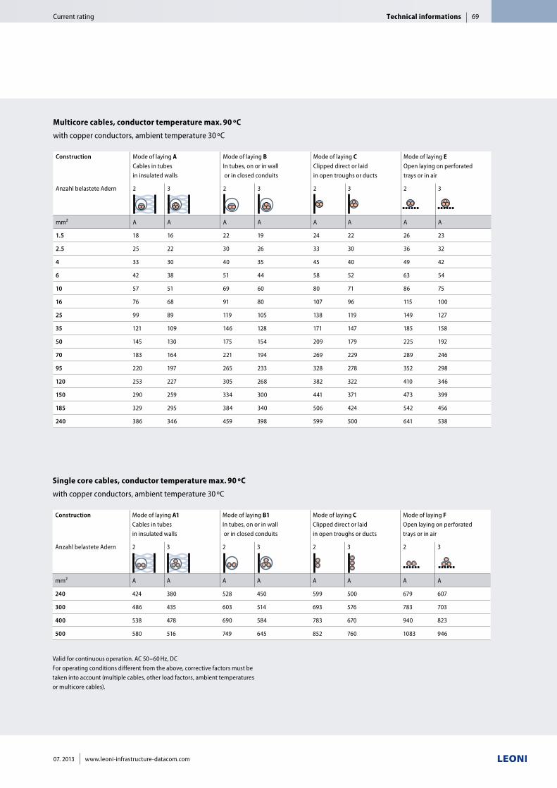
Multicore cables, conductor temperature max. 90 ºC
with copper conductors, ambient temperature 30 ºC
Construction Mode of laying A Cables in tubes in insulated walls
Mode of laying B In tubes, on or in wall or in closed conduits
Mode of laying C Clipped direct or laid in open troughs or ducts
Mode of laying E Open laying on perforated trays or in air
Anzahl belastete Adern 2 3 2 3 2 3 2 3
mm² A A A A A A A A
1.5 18 16 22 19 24 22 26 23
2.5 25 22 30 26 33 30 36 32
4 33 30 40 35 45 40 49 42
6 42 38 51 44 58 52 63 54
10 57 51 69 60 80 71 86 75
16 76 68 91 80 107 96 115 100
25 99 89 119 105 138 119 149 127
35 121 109 146 128 171 147 185 158
50 145 130 175 154 209 179 225 192
70 183 164 221 194 269 229 289 246
95 220 197 265 233 328 278 352 298
120 253 227 305 268 382 322 410 346
150 290 259 334 300 441 371 473 399
185 329 295 384 340 506 424 542 456
240 386 346 459 398 599 500 641 538
Valid for continuous operation. AC 50–60 Hz, DCFor operating conditions different from the above, corrective factors must be taken into account (multiple cables, other load factors, ambient temperatures or multicore cables).
Single core cables, conductor temperature max. 90 ºC
with copper conductors, ambient temperature 30 ºC
Construction Mode of laying A1 Cables in tubes in insulated walls
Mode of laying B1 In tubes, on or in wall or in closed conduits
Mode of laying C Clipped direct or laid in open troughs or ducts
Mode of laying F Open laying on perforated trays or in air
Anzahl belastete Adern 2 3 2 3 2 3 2 3
mm² A A A A A A A A
240 424 380 528 450 599 500 679 607
300 486 435 603 514 693 576 783 703
400 538 478 690 584 783 670 940 823
500 580 516 749 645 852 760 1083 946
Technical informationsCurrent rating 69
07. 2013 www.leoni-infrastructure-datacom.com
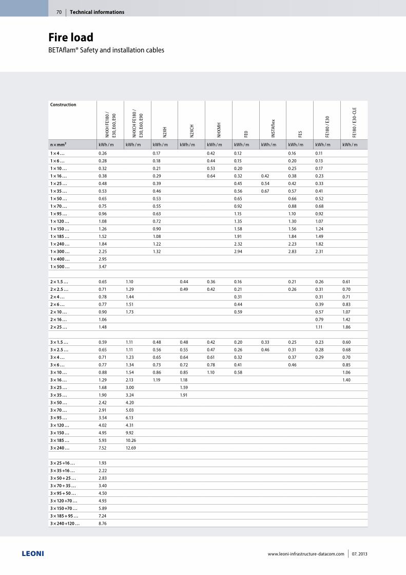
ConstructionN
HXH
FE1
80 /
E30,
E60,
E90
NH
XCH
FE1
80 /
E30,
E60,
E90
N2X
H
N2X
CH
NH
XMH
FE0
INST
Afle
x
FE5
FE18
0 / E
30
FE18
0 / E
30-C
LE
n × mm² kWh / m kWh / m kWh / m kWh / m kWh / m kWh / m kWh / m kWh / m kWh / m kWh / m
1 × 4 … 0.26 0.17 0.42 0.12 0.16 0.11
1 × 6 … 0.28 0.18 0.44 0.15 0.20 0.13
1 × 10 … 0.32 0.21 0.53 0.20 0.25 0.17
1 × 16 … 0.38 0.29 0.64 0.32 0.42 0.38 0.23
1 × 25 … 0.48 0.39 0.45 0.54 0.42 0.33
1 × 35 … 0.53 0.46 0.56 0.67 0.57 0.41
1 × 50 … 0.65 0.53 0.65 0.66 0.52
1 × 70 … 0.75 0.55 0.92 0.88 0.68
1 × 95 … 0.96 0.63 1.15 1.10 0.92
1 × 120 … 1.08 0.72 1.35 1.30 1.07
1 × 150 … 1.26 0.90 1.58 1.56 1.24
1 × 185 … 1.52 1.08 1.91 1.84 1.49
1 × 240 … 1.84 1.22 2.32 2.23 1.82
1 × 300 … 2.25 1.32 2.94 2.83 2.31
1 × 400 … 2.95
1 × 500 … 3.47
2 × 1.5 … 0.65 1.10 0.44 0.36 0.16 0.21 0.26 0.61
2 × 2.5 … 0.71 1.29 0.49 0.42 0.21 0.26 0.31 0.70
2 × 4 … 0.78 1.44 0.31 0.31 0.71
2 × 6 … 0.77 1.51 0.44 0.39 0.83
2 × 10 … 0.90 1.73 0.59 0.57 1.07
2 × 16 … 1.06 0.79 1.42
2 × 25 … 1.48 1.11 1.86
3 × 1.5 … 0.59 1.11 0.48 0.48 0.42 0.20 0.33 0.25 0.23 0.60
3 × 2.5 … 0.65 1.11 0.56 0.55 0.47 0.26 0.46 0.31 0.28 0.68
3 × 4 … 0.71 1.23 0.65 0.64 0.61 0.32 0.37 0.29 0.70
3 × 6 … 0.77 1.34 0.73 0.72 0.78 0.41 0.46 0.85
3 × 10 … 0.88 1.54 0.86 0.85 1.10 0.58 1.06
3 × 16 … 1.29 2.13 1.19 1.18 1.40
3 × 25 … 1.68 3.00 1.59
3 × 35 … 1.90 3.24 1.91
3 × 50 … 2.42 4.20
3 × 70 … 2.91 5.03
3 × 95 … 3.54 6.13
3 × 120 … 4.02 4.31
3 × 150 … 4.95 9.92
3 × 185 … 5.93 10.26
3 × 240 … 7.52 12.69
3 × 25 +16 … 1.93
3 × 35 +16 … 2.22
3 × 50 + 25 … 2.83
3 × 70 + 35 … 3.40
3 × 95 + 50 … 4.50
3 × 120 +70 … 4.93
3 × 150 +70 … 5.89
3 × 185 + 95 … 7.24
3 × 240 +120 … 8.76
Fire load BETAflam® Safety and installation cables
Technical informations70
www.leoni-infrastructure-datacom.com 07. 2013
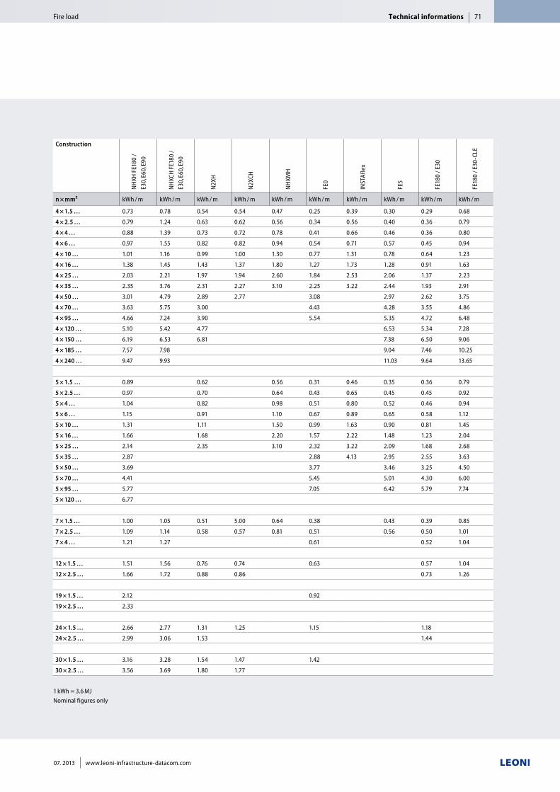
1 kWh = 3.6 MJNominal figures only
Construction
NH
XH F
E180
/ E3
0, E6
0, E9
0
NH
XCH
FE1
80 /
E30,
E60,
E90
N2X
H
N2X
CH
NH
XMH
FE0
INST
Afle
x
FE5
FE18
0 / E
30
FE18
0 / E
30-C
LE
n × mm² kWh / m kWh / m kWh / m kWh / m kWh / m kWh / m kWh / m kWh / m kWh / m kWh / m
4 × 1.5 … 0.73 0.78 0.54 0.54 0.47 0.25 0.39 0.30 0.29 0.68
4 × 2.5 … 0.79 1.24 0.63 0.62 0.56 0.34 0.56 0.40 0.36 0.79
4 × 4 … 0.88 1.39 0.73 0.72 0.78 0.41 0.66 0.46 0.36 0.80
4 × 6 … 0.97 1.55 0.82 0.82 0.94 0.54 0.71 0.57 0.45 0.94
4 × 10 … 1.01 1.16 0.99 1.00 1.30 0.77 1.31 0.78 0.64 1.23
4 × 16 … 1.38 1.45 1.43 1.37 1.80 1.27 1.73 1.28 0.91 1.63
4 × 25 … 2.03 2.21 1.97 1.94 2.60 1.84 2.53 2.06 1.37 2.23
4 × 35 … 2.35 3.76 2.31 2.27 3.10 2.25 3.22 2.44 1.93 2.91
4 × 50 … 3.01 4.79 2.89 2.77 3.08 2.97 2.62 3.75
4 × 70 … 3.63 5.75 3.00 4.43 4.28 3.55 4.86
4 × 95 … 4.66 7.24 3.90 5.54 5.35 4.72 6.48
4 × 120 … 5.10 5.42 4.77 6.53 5.34 7.28
4 × 150 … 6.19 6.53 6.81 7.38 6.50 9.06
4 × 185 … 7.57 7.98 9.04 7.46 10.25
4 × 240 … 9.47 9.93 11.03 9.64 13.65
5 × 1.5 … 0.89 0.62 0.56 0.31 0.46 0.35 0.36 0.79
5 × 2.5 … 0.97 0.70 0.64 0.43 0.65 0.45 0.45 0.92
5 × 4 … 1.04 0.82 0.98 0.51 0.80 0.52 0.46 0.94
5 × 6 … 1.15 0.91 1.10 0.67 0.89 0.65 0.58 1.12
5 × 10 … 1.31 1.11 1.50 0.99 1.63 0.90 0.81 1.45
5 × 16 … 1.66 1.68 2.20 1.57 2.22 1.48 1.23 2.04
5 × 25 … 2.14 2.35 3.10 2.32 3.22 2.09 1.68 2.68
5 × 35 … 2.87 2.88 4.13 2.95 2.55 3.63
5 × 50 … 3.69 3.77 3.46 3.25 4.50
5 × 70 … 4.41 5.45 5.01 4.30 6.00
5 × 95 … 5.77 7.05 6.42 5.79 7.74
5 × 120 … 6.77
7 × 1.5 … 1.00 1.05 0.51 5.00 0.64 0.38 0.43 0.39 0.85
7 × 2.5 … 1.09 1.14 0.58 0.57 0.81 0.51 0.56 0.50 1.01
7 × 4 … 1.21 1.27 0.61 0.52 1.04
12 × 1.5 … 1.51 1.56 0.76 0.74 0.63 0.57 1.04
12 × 2.5 … 1.66 1.72 0.88 0.86 0.73 1.26
19 × 1.5 … 2.12 0.92
19 × 2.5 … 2.33
24 × 1.5 … 2.66 2.77 1.31 1.25 1.15 1.18
24 × 2.5 … 2.99 3.06 1.53 1.44
30 × 1.5 … 3.16 3.28 1.54 1.47 1.42
30 × 2.5 … 3.56 3.69 1.80 1.77
Technical informationsFire load 71
07. 2013 www.leoni-infrastructure-datacom.com
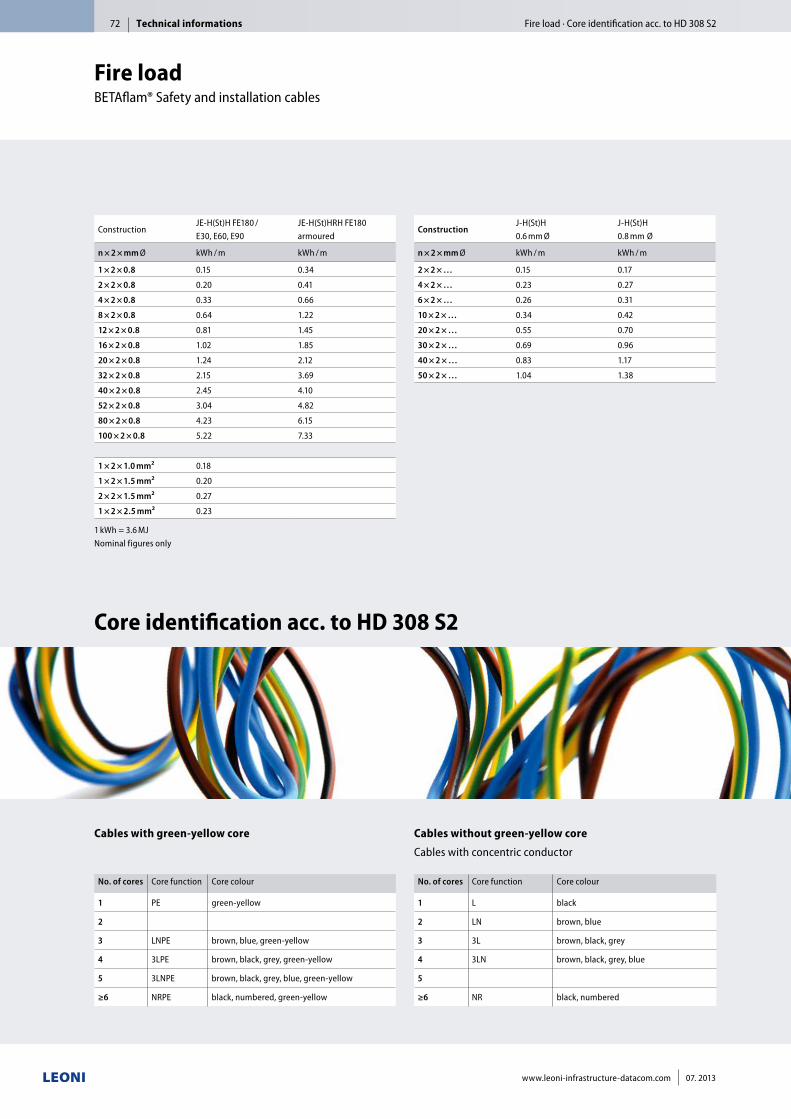
No. of cores Core function Core colour
1 PE green-yellow
2
3 LNPE brown, blue, green-yellow
4 3LPE brown, black, grey, green-yellow
5 3LNPE brown, black, grey, blue, green-yellow
≥6 NRPE black, numbered, green-yellow
Cables with green-yellow core
No. of cores Core function Core colour
1 L black
2 LN brown, blue
3 3L brown, black, grey
4 3LN brown, black, grey, blue
5
≥6 NR black, numbered
Cables without green-yellow core
Cables with concentric conductor
1 kWh = 3.6 MJNominal figures only
ConstructionJE-H(St)H FE180 / E30, E60, E90
JE-H(St)HRH FE180 armoured
n × 2 × mm Ø kWh / m kWh / m
1 × 2 × 0.8 0.15 0.34
2 × 2 × 0.8 0.20 0.41
4 × 2 × 0.8 0.33 0.66
8 × 2 × 0.8 0.64 1.22
12 × 2 × 0.8 0.81 1.45
16 × 2 × 0.8 1.02 1.85
20 × 2 × 0.8 1.24 2.12
32 × 2 × 0.8 2.15 3.69
40 × 2 × 0.8 2.45 4.10
52 × 2 × 0.8 3.04 4.82
80 × 2 × 0.8 4.23 6.15
100 × 2 × 0.8 5.22 7.33
1 × 2 × 1.0 mm² 0.18
1 × 2 × 1.5 mm² 0.20
2 × 2 × 1.5 mm² 0.27
1 × 2 × 2.5 mm² 0.23
ConstructionJ-H(St)H0.6 mm Ø
J-H(St)H0.8 mm Ø
n × 2 × mm Ø kWh / m kWh / m
2 × 2 × … 0.15 0.17
4 × 2 × … 0.23 0.27
6 × 2 × … 0.26 0.31
10 × 2 × … 0.34 0.42
20 × 2 × … 0.55 0.70
30 × 2 × … 0.69 0.96
40 × 2 × … 0.83 1.17
50 × 2 × … 1.04 1.38
Core identification acc. to HD 308 S2
Fire load BETAflam® Safety and installation cables
Technical informations Fire load · Core identification acc. to HD 308 S272
www.leoni-infrastructure-datacom.com 07. 2013
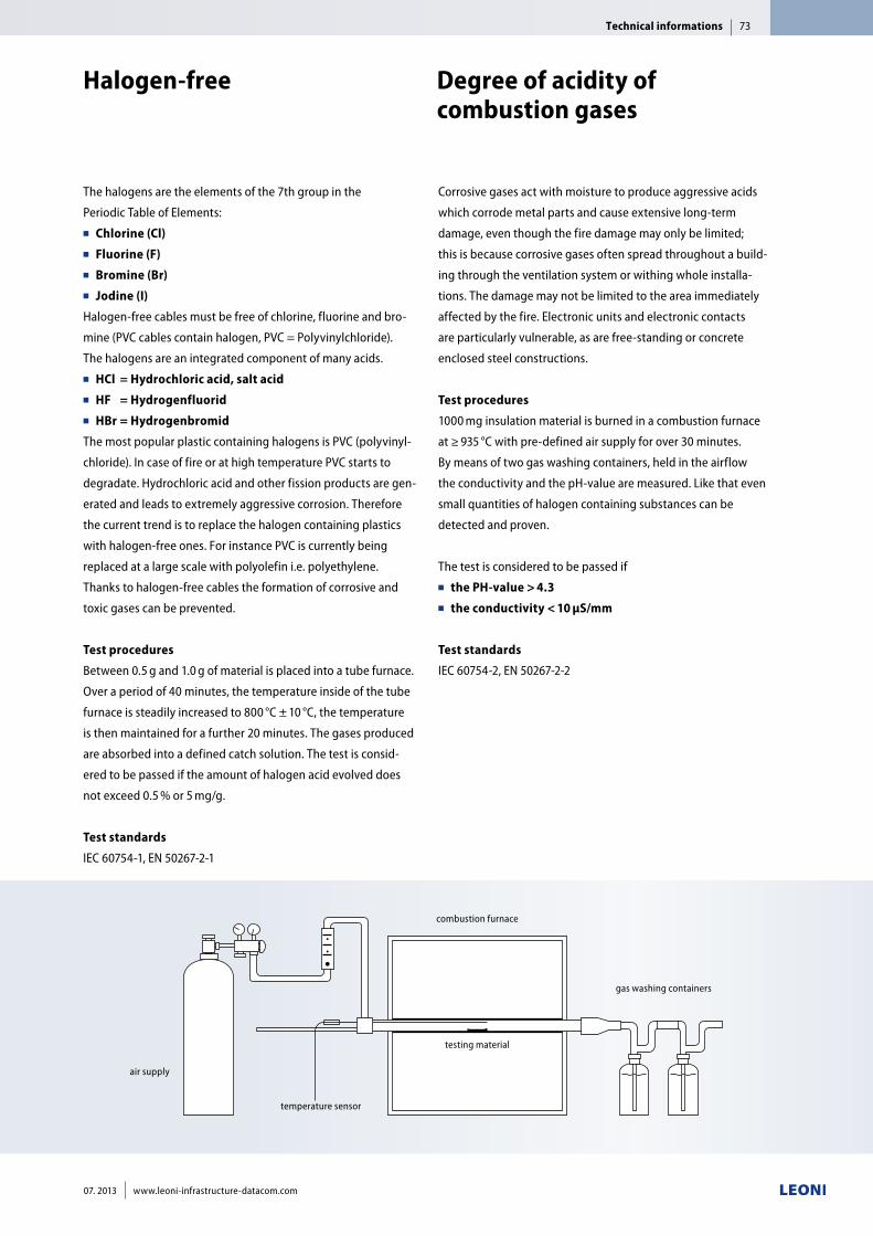
Corrosive gases act with moisture to produce aggressive acids
which corrode metal parts and cause extensive long-term
damage, even though the fire damage may only be limited;
this is because corrosive gases often spread throughout a build-
ing through the ventilation system or withing whole installa-
tions. The damage may not be limited to the area immediately
affected by the fire. Electronic units and electronic contacts
are particularly vulnerable, as are free-standing or concrete
enclosed steel constructions.
Test procedures
1000 mg insulation material is burned in a combustion furnace
at ≥ 935 °C with pre-defined air supply for over 30 minutes.
By means of two gas washing containers, held in the airflow
the conductivity and the pH-value are measured. Like that even
small quantities of halogen containing substances can be
detected and proven.
The test is considered to be passed if ■■ the PH-value > 4.3■■ the conductivity < 10 µS/mm
Test standards
IEC 60754-2, EN 50267-2-2
The halogens are the elements of the 7th group in the
Periodic Table of Elements: ■■ Chlorine (Cl)■■ Fluorine (F)■■ Bromine (Br)■■ Jodine (I)
Halogen-free cables must be free of chlorine, fluorine and bro-
mine (PVC cables contain halogen, PVC = Polyvinylchloride).
The halogens are an integrated component of many acids.■■ HCl = Hydrochloric acid, salt acid■■ HF = Hydrogenfluorid ■■ HBr = Hydrogenbromid
The most popular plastic containing halogens is PVC (polyvinyl-
chloride). In case of fire or at high temperature PVC starts to
degradate. Hydrochloric acid and other fission products are gen-
erated and leads to extremely aggressive corrosion. Therefore
the current trend is to replace the halogen containing plastics
with halogen-free ones. For instance PVC is currently being
replaced at a large scale with polyolefin i.e. polyethylene.
Thanks to halogen-free cables the formation of corrosive and
toxic gases can be prevented.
Test procedures
Between 0.5 g and 1.0 g of material is placed into a tube furnace.
Over a period of 40 minutes, the temperature inside of the tube
furnace is steadily increased to 800 °C ± 10 °C, the temperature
is then maintained for a further 20 minutes. The gases produced
are absorbed into a defined catch solution. The test is consid-
ered to be passed if the amount of halogen acid evolved does
not exceed 0.5 % or 5 mg/g.
Test standards
IEC 60754-1, EN 50267-2-1
air supply
combustion furnace
testing material
gas washing containers
temperature sensor
Halogen-free Degree of acidity of combustion gases
Technical informations 73
07. 2013 www.leoni-infrastructure-datacom.com
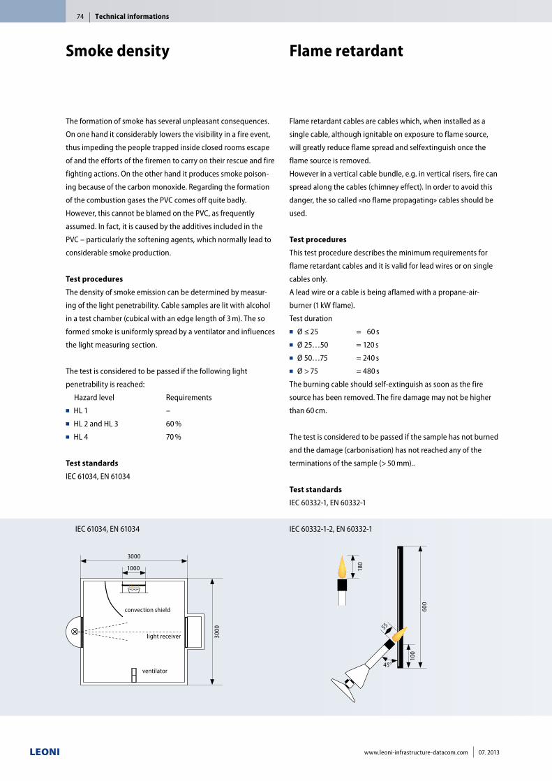
Flame retardant cables are cables which, when installed as a
single cable, although ignitable on exposure to flame source,
will greatly reduce flame spread and selfextinguish once the
flame source is removed.
However in a vertical cable bundle, e.g. in vertical risers, fire can
spread along the cables (chimney effect). In order to avoid this
danger, the so called «no flame propagating» cables should be
used.
Test procedures
This test procedure describes the minimum requirements for
flame retardant cables and it is valid for lead wires or on single
cables only.
A lead wire or a cable is being aflamed with a propane-air-
burner (1 kW flame).
Test duration■■ Ø ≤ 25 = 60 s■■ Ø 25…50 = 120 s■■ Ø 50…75 = 240 s■■ Ø > 75 = 480 s
The burning cable should self-extinguish as soon as the fire
source has been removed. The fire damage may not be higher
than 60 cm.
The test is considered to be passed if the sample has not burned
and the damage (carbonisation) has not reached any of the
terminations of the sample (> 50 mm)..
Test standards
IEC 60332-1, EN 60332-1
IEC 60332-1-2, EN 60332-1
The formation of smoke has several un pleasant consequences.
On one hand it considerably lowers the visibility in a fire event,
thus impeding the people trapped inside closed rooms escape
of and the efforts of the firemen to carry on their rescue and fire
fighting actions. On the other hand it produces smoke poison-
ing because of the carbon monoxide. Regarding the formation
of the combustion gases the PVC comes off quite badly.
However, this cannot be blamed on the PVC, as frequently
assumed. In fact, it is caused by the additives included in the
PVC – particularly the softening agents, which normally lead to
considerable smoke production.
Test procedures
The density of smoke emission can be determined by measur-
ing of the light penetrability. Cable samples are lit with alcohol
in a test chamber (cubical with an edge length of 3 m). The so
formed smoke is uniformly spread by a ventilator and influences
the light measuring section.
The test is considered to be passed if the following light
penetrability is reached:
Hazard level Requirements■■ HL 1 –■■ HL 2 and HL 3 60 %■■ HL 4 70 %
Test standards
IEC 61034, EN 61034
IEC 61034, EN 61034
Smoke density Flame retardant
Technical informations74
www.leoni-infrastructure-datacom.com 07. 2013
600
100
45°
55
180
3000
3000
1000
ventilator
light receiver
convection shield
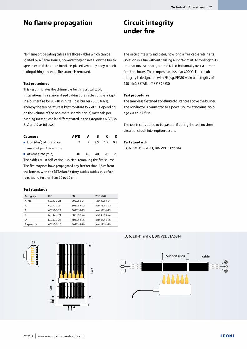
No flame propagating cables are those cables which can be
ignited by a flame source, however they do not allow the fire to
spread even if the cable bundle is placed vertically, they are self
extinguishing once the fire source is removed.
Test procedures
This test simulates the chimney effect in vertical cable
installations. In a standardized cabinet the cable bundle is kept
in a burner fire for 20 - 40 minutes (gas burner 75 ± 5 MJ/h).
Thereby the temperature is kept constant to 750 °C. Depending
on the volume of the non-metal (combustible) materials per
running meter it can be differentiated in the categories A F/R, A,
B, C und D as follows.
Category A F/R A B C D■■ Liter (dm³) of insulation 7 7 3.5 1.5 0.5
material per 1 m sample ■■ Aflame time (min) 40 40 40 20 20
The cables must self-extinguish after removing the fire source.
The fire may not have propagated any further than 2,5 m from
the burner. With the BETAflam® safety cables cables this often
reaches no further than 50 to 60 cm.
Test standards
Category IEC EN VDE 0482
A F/R 60332-3-21 60332-3-21 part 332-3-21
A 60332-3-22 60332-3-22 part 332-3-22
B 60332-3-23 60332-3-23 part 332-3-23
C 60332-3-24 60332-3-24 part 332-3-24
D 60332-3-25 60332-3-25 part 332-3-25
Apparatus 60332-3-10 60332-3-10 part 332-3-10
3500
500
100
75
IEC 60331-11 and -21, DIN VDE 0472-814
The circuit integrity indicates, how long a free cable retains its
isolation in a fire without causing a short-circuit. According to its
international standard, a cable is laid hoizontally over a burner
for three hours. The temperature is set at 800 °C. The circuit
integrity is designated with FE (e.g. FE180 = circuit integrity of
180 min): BETAflam® FE180 / E30
Test procedures
The sample is fastened at definited distances above the burner.
The conductor is connected to a power source at nominal volt-
age via an 2 A fuse.
The test is considered to be passed, if during the test no short
circuit or circuit interruption occurs.
Test standards
IEC 60331-11 and -21, DIN VDE 0472-814
Support rings cable
No flame propagation Circuit integrity under fire
Technical informations 75
07. 2013 www.leoni-infrastructure-datacom.com
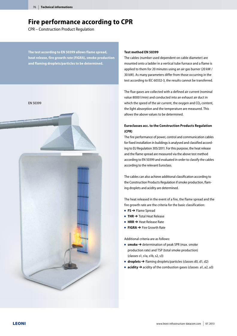
The test according to EN 50399 allows flame spread,
heat release, fire growth rate (FIGRA), smoke production
and flaming droplets/particles to be determined.
EN 50399
Test method EN 50399
The cables (number used dependent on cable diameter) are
mounted onto a ladder in a vertical tube furnace and a flame is
applied to them for 20 minutes using an air gas burner (20 kW /
30 kW). As many parameters differ from those occurring in the
test according to IEC 60332-3, the results cannot be transferred.
The flue gases are collected with a defined air current (nominal
value 8000 l/min) and conducted into an exhaust air duct in
which the speed of the air current, the oxygen and CO2 content,
the light absorption and the temperature are measured. This
allows the above values to be determined.
Euroclasses acc. to the Construction Products Regulation
(CPR)
The fire performance of power, control and communication cables
for fixed installation in buildings is analysed and classified accord-
ing to EU Regulation 305/2011. For this purpose, the heat release
and the flame spread are measured via the above test method
according to EN 50399 and evaluated in order to classify the cables
according to the relevant Euroclass.
The cables can also achieve additional classification according to
the Construction Products Regulation if smoke production, flam-
ing droplets and acidity are determined.
The heat released in the event of a fire, the flame spread and the
fire growth rate are the criteria for the basic classification: ■■ FS ➔■Flame Spread■■ THR ➔■Total Heat Release■■ HRR ➔■Heat Release Rate■■ FIGRA ➔■Fire Growth Rate
Additional criteria are as follows:■■ smoke ➔ determination of peak SPR (max. smoke
production rate) and TSP (total smoke production)
(classes s1, s1a, s1b, s2, s3)■■ droplets ➔■flaming droplets/particles (classes d0, d1, d2) ■■ acidity ➔ acidity of the combustion gases (classes a1, a2, a3)
Fire performance according to CPRCPR – Construction Product Regulation
Technical informations76
www.leoni-infrastructure-datacom.com 07. 2013
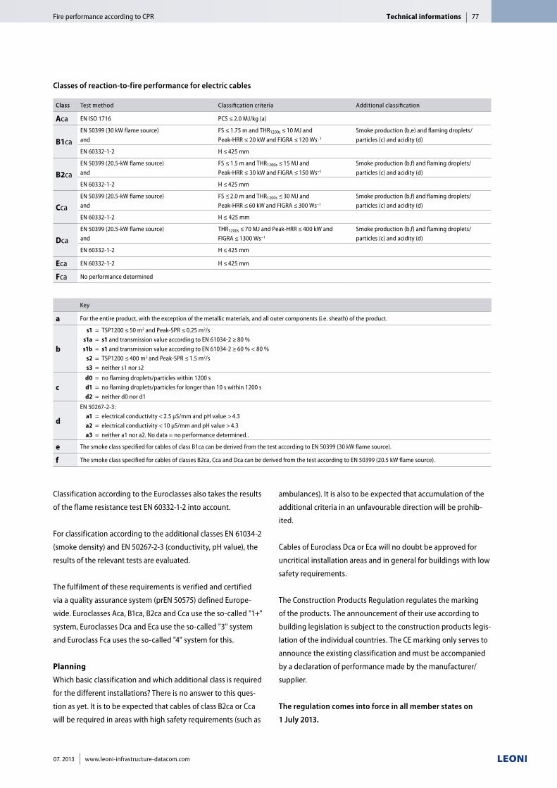
Classification according to the Euroclasses also takes the results
of the flame resistance test EN 60332-1-2 into account.
For classification according to the additional classes EN 61034-2
(smoke density) and EN 50267-2-3 (conductivity, pH value), the
results of the relevant tests are evaluated.
The fulfilment of these requirements is verified and certified
via a quality assurance system (prEN 50575) defined Europe-
wide. Euroclasses Aca, B1ca, B2ca and Cca use the so-called "1+"
system, Euroclasses Dca and Eca use the so-called "3" system
and Euroclass Fca uses the so-called "4" system for this.
Planning
Which basic classification and which additional class is required
for the different installations? There is no answer to this ques-
tion as yet. It is to be expected that cables of class B2ca or Cca
will be required in areas with high safety requirements (such as
ambulances). It is also to be expected that accumulation of the
additional criteria in an unfavourable direction will be prohib-
ited.
Cables of Euroclass Dca or Eca will no doubt be approved for
uncritical installation areas and in general for buildings with low
safety requirements.
The Construction Products Regulation regulates the marking
of the products. The announcement of their use according to
building legislation is subject to the construction products legis-
lation of the individual countries. The CE marking only serves to
announce the existing classification and must be accompanied
by a declaration of performance made by the manufacturer/
supplier.
The regulation comes into force in all member states on
1 July 2013.
Technical informationsFire performance according to CPR 77
07. 2013 www.leoni-infrastructure-datacom.com
Classes of reaction-to-fire performance for electric cables
Class Test method Classification criteria Additional classification
Aca EN ISO 1716 PCS ≤ 2.0 MJ/kg (a)
B1ca EN 50399 (30 kW flame source) and
FS ≤ 1.75 m and THR1200s ≤ 10 MJ and Peak-HRR ≤ 20 kW and FIGRA ≤ 120 Ws−1
Smoke production (b,e) and flaming droplets/ particles (c) and acidity (d)
EN 60332-1-2 H ≤ 425 mm
B2caEN 50399 (20.5-kW flame source) and
FS ≤ 1.5 m and THR1200s ≤ 15 MJ and Peak-HRR ≤ 30 kW and FIGRA ≤ 150 Ws−1
Smoke production (b,f) and flaming droplets/ particles (c) and acidity (d)
EN 60332-1-2 H ≤ 425 mm
CcaEN 50399 (20.5-kW flame source) and
FS ≤ 2.0 m and THR1200s ≤ 30 MJ and Peak-HRR ≤ 60 kW and FIGRA ≤ 300 Ws−1
Smoke production (b,f) and flaming droplets/ particles (c) and acidity (d)
EN 60332-1-2 H ≤ 425 mm
DcaEN 50399 (20.5-kW flame source) and
THR1200s ≤ 70 MJ and Peak-HRR ≤ 400 kW and FIGRA ≤ 1300 Ws−1
Smoke production (b,f) and flaming droplets/ particles (c) and acidity (d)
EN 60332-1-2 H ≤ 425 mm
Eca EN 60332-1-2 H ≤ 425 mm
Fca No performance determined
Key
a For the entire product, with the exception of the metallic materials, and all outer components (i.e. sheath) of the product.
b
s1 = TSP1200 ≤ 50 m2 and Peak-SPR ≤ 0.25 m2/s s1a = s1 and transmission value according to EN 61034-2 ≥ 80 % s1b = s1 and transmission value according to EN 61034-2 ≥ 60 % < 80 %
s2 = TSP1200 ≤ 400 m2 and Peak-SPR ≤ 1.5 m2/s s3 = neither s1 nor s2
c d0 = no flaming droplets/particles within 1200 s d1 = no flaming droplets/particles for longer than 10 s within 1200 s d2 = neither d0 nor d1
d
EN 50267-2-3: a1 = electrical conductivity < 2.5 μS/mm and pH value > 4.3 a2 = electrical conductivity < 10 μS/mm and pH value > 4.3 a3 = neither a1 nor a2. No data = no performance determined..
e The smoke class specified for cables of class B1ca can be derived from the test according to EN 50399 (30 kW flame source).
f The smoke class specified for cables of classes B2ca, Cca and Dca can be derived from the test according to EN 50399 (20.5 kW flame source).
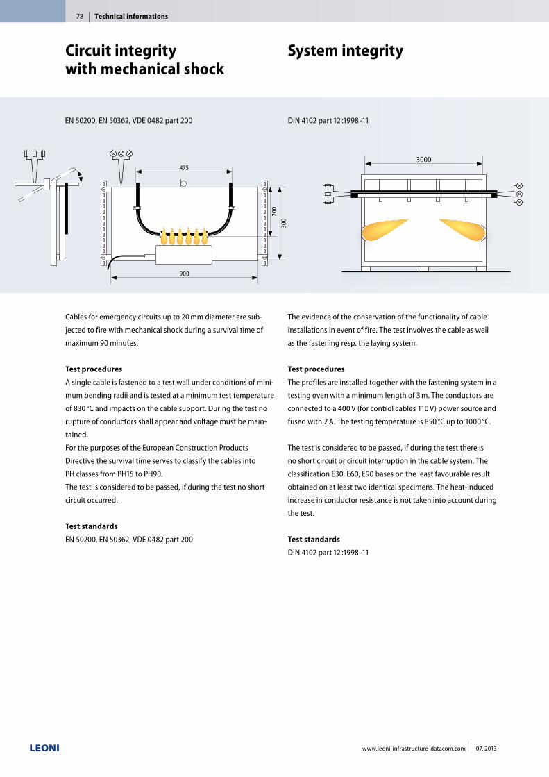
The evidence of the conservation of the functionality of cable
installations in event of fire. The test involves the cable as well
as the fastening resp. the laying system.
Test procedures
The profiles are installed together with the fastening system in a
testing oven with a minimum length of 3 m. The conductors are
connected to a 400 V (for control cables 110 V) power source and
fused with 2 A. The testing temperature is 850 °C up to 1000 °C.
The test is considered to be passed, if during the test there is
no short circuit or circuit interruption in the cable system. The
classification E30, E60, E90 bases on the least favourable result
obtained on at least two identical specimens. The heat-induced
increase in conductor resistance is not taken into account during
the test.
Test standards
DIN 4102 part 12 :1998 -11
System integrity
DIN 4102 part 12 :1998 -11
3000
Technical informations78
www.leoni-infrastructure-datacom.com 07. 2013
Cables for emergency circuits up to 20 mm diameter are sub-
jected to fire with mechanical shock during a survival time of
maximum 90 minutes.
Test procedures
A single cable is fastened to a test wall under conditions of mini-
mum bending radii and is tested at a minimum test temperature
of 830 °C and impacts on the cable support. During the test no
rupture of conductors shall appear and voltage must be main-
tained.
For the purposes of the European Construction Products
Directive the survival time serves to classify the cables into
PH classes from PH15 to PH90.
The test is considered to be passed, if during the test no short
circuit occurred.
Test standards
EN 50200, EN 50362, VDE 0482 part 200
EN 50200, EN 50362, VDE 0482 part 200
Circuit integrity with mechanical shock
475
300
200
900
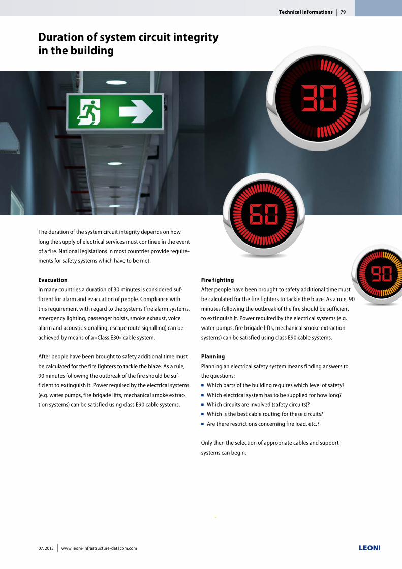
The duration of the system circuit integrity depends on how
long the supply of electrical services must continue in the event
of a fire. National legislations in most countries provide require-
ments for safety systems which have to be met.
Evacuation
In many countries a duration of 30 minutes is considered suf-
ficient for alarm and evacuation of people. Compliance with
this requirement with regard to the systems (fire alarm systems,
emergency lighting, passenger hoists, smoke exhaust, voice
alarm and acoustic signalling, escape route signalling) can be
achieved by means of a «Class E30» cable system.
After people have been brought to safety additional time must
be calculated for the fire fighters to tackle the blaze. As a rule,
90 minutes following the outbreak of the fire should be suf-
ficient to extinguish it. Power required by the electrical systems
(e.g. water pumps, fire brigade lifts, mechanical smoke extrac-
tion systems) can be satisfied using class E90 cable systems.
Duration of system circuit integrity in the building
Fire fighting
After people have been brought to safety additional time must
be calculated for the fire fighters to tackle the blaze. As a rule, 90
minutes following the outbreak of the fire should be sufficient
to extinguish it. Power required by the electrical systems (e.g.
water pumps, fire brigade lifts, mechanical smoke extraction
systems) can be satisfied using class E90 cable systems.
Planning
Planning an electrical safety system means finding answers to
the questions:■■ Which parts of the building requires which level of safety?■■ Which electrical system has to be supplied for how long?■■ Which circuits are involved (safety circuits)? ■■ Which is the best cable routing for these circuits? ■■ Are there restrictions concerning fire load, etc.?
Only then the selection of appropriate cables and support
systems can begin.
Technical informations 79
07. 2013 www.leoni-infrastructure-datacom.com
Technical informations80
www.leoni-infrastructure-datacom.com 07. 2013
Application
BETAfixss® supporting systems are applied for electrical cable
installations with system circuit integrity in case of fire. Further-
more, they provide a fire proof fixing of the laid cables between
storey ceiling and intermediate ceilings rated F30 or F90.
Note:
Specifications are valid
at time of printing.
Product group Valid Approval no. Classification
BETAflam® NHXH E30 - E60 10 February 2015 P-MPA-E-05-008 E30, E60
BETAflam® NHXCH E30 - E60 10 February 2015 P-MPA-E-05-008 E30, E60
BETAflam® JE-H(St)H E30 10 February 2015 P-MPA-E-05-008 E30
BETAflam® JE-H(St)HRH E30 10 February 2015 P-MPA-E-05-008 E30
BETAflam® NHXH E90 10 February 2015 P-MPA-E-05-008 E90
BETAflam® NHXCH E90 10 February 2015 P-MPA-E-05-008 E90
BETAflam® JE-H(St)H E30 - E90 10 February 2015 P-MPA-E-05-008 E30, E60, E90
BETAflam® JE-H(St)HRH E30 - E90 10 February 2015 P-MPA-E-05-008 E30, E60, E90
BETAflam® JE-H(St)H E30 SIR 06 May 2017 P-MPA-E-12-008 E30, E60
BETAflam® JE-HH FE180/E30 SIR 09 September 2017 P-MPA-E-12-012 E30, E60
BETAflam® Approval
MPA NRW Dortmund, Germany
Product group Valid Approval no. Classification
BETAflam® NHXH E90 ≥ 2.5 mm2 21 July 2016 G 4980033 E90
BETAflam® NHXCH E90 ≥ 2.5 mm2 21 July 2016 G 4980034 E90
BETAflam® Approval
VdS Schadenverhütung GmbH, Cologne, Germany
Anbieter Valid Approval no. Classification
OBO Bettermann 31 December 2017 P-MPA-E-05-030 E30, E60, E90
PUK-Werke 31 December 2017 P-MPA-E-05-030 E30, E60, E90
PUK-Werke 10 August 2017 P-MPA-E-07-022 E30, E60, E90
RICO GmbH 31 December 2017 P-MPA-E-05-030 E30, E60, E90
NIEDAX GmbH & Co. KG 31 December 2017 P-MPA-E-05-030 E30, E60, E90
HILTI Germany GmbH 31 December 2017 P-MPA-E-05-030 E30, E60, E90
BETAflam® Approval
with other producers of support systems
MPA NRW Dortmund, Germany
BETAflam® Approvals
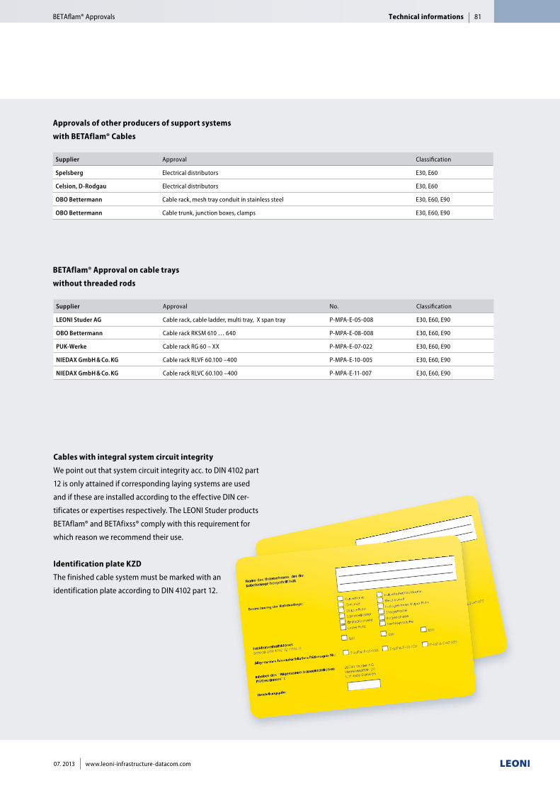
Technical informations 81
07. 2013 www.leoni-infrastructure-datacom.com
Cables with integral system circuit integrity
We point out that system circuit integrity acc. to DIN 4102 part
12 is only attained if corresponding laying systems are used
and if these are installed according to the effective DIN cer-
tificates or expertises respectively. The LEONI Studer products
BETAflam® and BETAfixss® comply with this requirement for
which reason we recommend their use.
Identification plate KZD
The finished cable system must be marked with an
identification plate according to DIN 4102 part 12.
Supplier Approval Classification
Spelsberg Electrical distributors E30, E60
Celsion, D-Rodgau Electrical distributors E30, E60
OBO Bettermann Cable rack, mesh tray conduit in stainless steel E30, E60, E90
OBO Bettermann Cable trunk, junction boxes, clamps E30, E60, E90
Supplier Approval No. Classification
LEONI Studer AG Cable rack, cable ladder, multi tray, X span tray P-MPA-E-05-008 E30, E60, E90
OBO Bettermann Cable rack RKSM 610 … 640 P-MPA-E-08-008 E30, E60, E90
PUK-Werke Cable rack RG 60 – XX P-MPA-E-07-022 E30, E60, E90
NIEDAX GmbH & Co. KG Cable rack RLVF 60.100 –400 P-MPA-E-10-005 E30, E60, E90
NIEDAX GmbH & Co. KG Cable rack RLVC 60.100 –400 P-MPA-E-11-007 E30, E60, E90
Approvals of other producers of support systems
with BETAflam® Cables
BETAflam® Approval on cable trays
without threaded rods
BETAflam® Approvals
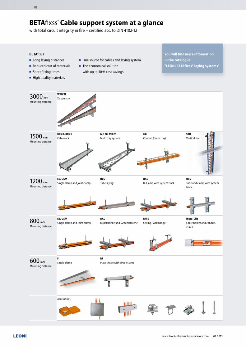
3000 mmMounting distance
WSB XL X span tray
1500 mmMounting distance
KR 20, KR 25 Cable rack
MB 20, MB 25 Multi tray system
GK Conduit (mesh tray)
STR Vertical riser
1200 mmMounting distance
ES, GSM Single clamp and joint clamp
RES Tube laying
BAC U-Clamp with System track
RBS Tube and clamp with system track
800 mmMounting distance
ES, GSM Single clamp and Joint clamp
BAC Bügelschelle und Systemschiene
DWS Ceiling / wall hanger
Insta-Clic Cable holder and conduit, 2-in-1
600 mmMounting distance
F Single clamp
RF Plastic tube with single clamp
Accessories
BETAfixss® ■■ Long laying distances■■ Reduced cost of materials■■ Short fitting times■■ High quality materials
BETAfixss® Cable support system at a glancewith total circuit integrity in fire – certified acc. to DIN 4102-12
■■ One source for cables and laying system■■ The economical solution
with up to 30 % cost savings!
You will find more information
in the catalogue
"LEONI BETAfixss® laying systems"
82
www.leoni-infrastructure-datacom.com 07. 2013
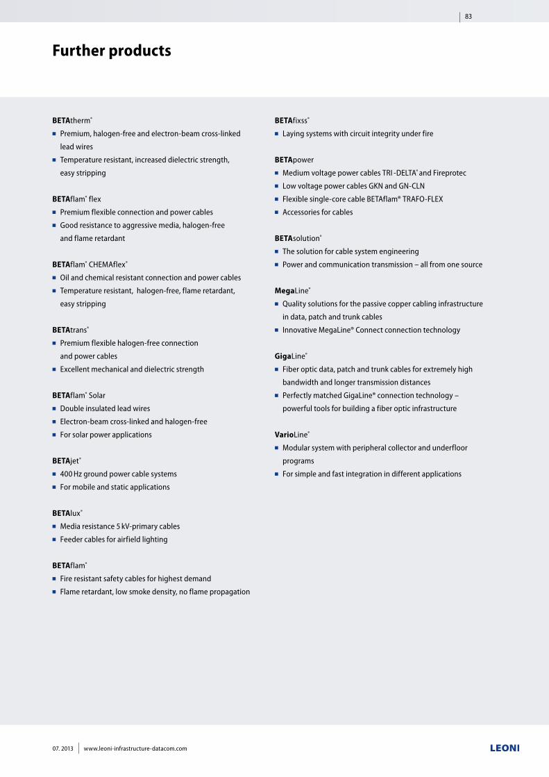
BETAtherm® ■■ Premium, halogen-free and electron-beam cross-linked
lead wires■■ Temperature resistant, increased dielectric strength,
easy stripping
BETAflam® flex ■■ Premium flexible connection and power cables■■ Good resistance to aggressive media, halogen-free
and flame retardant
BETAflam® CHEMAflex®
■■ Oil and chemical resistant connection and power cables■■ Temperature resistant, halogen-free, flame retardant,
easy stripping
BETAtrans® ■■ Premium flexible halogen-free connection
and power cables■■ Excellent mechanical and dielectric strength
BETAflam® Solar■■ Double insulated lead wires■■ Electron-beam cross-linked and halogen-free■■ For solar power applications
BETAjet® ■■ 400 Hz ground power cable systems■■ For mobile and static applications
BETAlux® ■■ Media resistance 5 kV-primary cables■■ Feeder cables for airfield lighting
BETAflam® ■■ Fire resistant safety cables for highest demand■■ Flame retardant, low smoke density, no flame propagation
BETAfixss® ■■ Laying systems with circuit integrity under fire
BETApower■■ Medium voltage power cables TRI -DELTA® and Fireprotec■■ Low voltage power cables GKN and GN-CLN■■ Flexible single-core cable BETAflam® TRAFO-FLEX■■ Accessories for cables
BETAsolution®
■■ The solution for cable system engineering■■ Power and communication transmission – all from one source
MegaLine®
■■ Quality solutions for the passive copper cabling infrastructure
in data, patch and trunk cables■■ Innovative MegaLine® Connect connection technology
GigaLine®
■■ Fiber optic data, patch and trunk cables for extremely high
bandwidth and longer transmission distances■■ Perfectly matched GigaLine® connection technology –
powerful tools for building a fiber optic infrastructure
VarioLine®
■■ Modular system with peripheral collector and underfloor
programs■■ For simple and fast integration in different applications
Further products
83
07. 2013 www.leoni-infrastructure-datacom.com
07. 20
13 / en
_100
0
LEONI Studer AG
Herrenmattstrasse 20
4658 Daeniken
Switzerland
Phone +41 (0)62 288 82 82
Fax +41 (0)62 288 83 83
Find out more:
Business Unit Infrastructure & Datacominfrastructure-datacom@leoni.comwww.leoni-infrastructure-datacom.com
LEONI Kerpen GmbH
Zweifaller Strasse 275–287
52224 Stolberg
Germany
Phone +49 (0)2402 17 1
Fax +49 (0)2402 75154