Embed Size (px)
Citation preview

9124956
EN

Version: 1-1.00 Language: English Date: 11/2011 Reviewer: TZ
Dresdener Strasse 88 D-02625 Bautzen, Germany
Tel.: +49 (0) 3591 / 360-0 Fax: +49 (0) 3591 / 360-140
Emergency phone outside of business hours: The telephone number can be found on the
service label at the front of the oven.
Emergency telephone (if no service label is affixed): +49 (0) 170 / 2236000
Email: [email protected]
Internet: www.debag.com

Deutsche Backofenbau GmbH +49 / (0)3591/360-0
1 TABLE OF CONTENTS
Page
1 Table of Contents .......................................................................................................................... 3
2 Preface............................................................................................................................................ 5
3 Safety Information ......................................................................................................................... 6 3.1 Symbols Used.......................................................................................................................... 6 3.2 General Information ................................................................................................................. 6 3.3 Intended Use ........................................................................................................................... 7 3.4 Work and Health Protection ..................................................................................................... 8 3.5 Warranty and Liability ............................................................................................................ 10
4 Oven Structure and Baking Principles ...................................................................................... 10
5 Technical Data (Exerpt) .............................................................................................................. 11
6 Instructions before Commissioning .......................................................................................... 12 6.1 Oven Connections and Operating Elements ......................................................................... 12 6.2 Location ................................................................................................................................. 13 6.3 Requirements for the Substructure........................................................................................ 13 6.4 Transport and Setup .............................................................................................................. 14 6.5 Electrical Connection ............................................................................................................. 14 6.6 Water Connection .................................................................................................................. 15
6.6.1 Ovens with fixed water connection .................................................................................. 15 6.6.2 Ovens with Water Tank ................................................................................................... 15
6.7 Condensate Drain .................................................................................................................. 16 6.8 Exhaust Air ............................................................................................................................ 16
6.8.1 Ovens without vaporisation .............................................................................................. 16 6.8.2 Ovens with vaporisation ................................................................................................... 17 6.8.3 Exhaust Steam Condenser (ESC) ................................................................................... 17
6.9 Commissioning - Initial Operation.......................................................................................... 18
7 Decommissioning ....................................................................................................................... 18
8 Oven Controller ........................................................................................................................... 19
9 Standard Baking Process ........................................................................................................... 20 9.1 Opening and Closing the Baking Chamber Door .................................................................. 20 9.2 Baking Start ........................................................................................................................... 21 9.3 Select Baking Program and Oven Assignment ..................................................................... 21 9.4 Preparing the Raw Goods ..................................................................................................... 22 9.5 Loading the Raw Goods ........................................................................................................ 22 9.6 Baking .................................................................................................................................... 23 9.7 Removing the Baked Goods .................................................................................................. 23 9.8 End of Baking ........................................................................................................................ 24
10 Cleaning ....................................................................................................................................... 25 10.1 Removing the Baking Sheet Supports .................................................................................. 26 10.2 Opening the Internal Glass Pane of the Baking Chamber Door ........................................... 26
11 Oven Maintenance ....................................................................................................................... 27
Operating Manual Shop Oven DiLa Part 1 - Oven Page 3

Deutsche Backofenbau GmbH +49 / (0)3591/360-0
11.1 Replacing a Faulty Oven Lamp ............................................................................................. 27
12 Faults and Error Messages ........................................................................................................ 28 12.1 Non-Resettable Faults ........................................................................................................... 28 12.2 Resettable Faults ................................................................................................................... 28
13 Appendix: LED Remaining Baking Time Display ..................................................................... 29
14 Appendix: Twin Ovens ................................................................................................................ 31 14.1 Instructions Before Commissioning ....................................................................................... 31 14.2 Notes on Instructions ............................................................................................................. 32
15 Appendix: DiLa D ........................................................................................................................ 33 15.1 Opening and Cleaning of the Glass Rear Wall ...................................................................... 33
16 Appendix: DiLa B ........................................................................................................................ 35 16.1 Specifics of Oven Operation .................................................................................................. 35 16.2 Cleaning 2nd Baking chamber Door ..................................................................................... 35
17 Appendix: EasyClean .................................................................................................................. 37
18 Appendix: Loading Trolley ......................................................................................................... 39
19 Appendix: Declaration of Conformity ....................................................................................... 41
Page 4 Operating Manual Shop Oven DiLa Part 1 - Oven

Deutsche Backofenbau GmbH +49 / (0)3591/360-0
Operating Manual Shop Oven DiLa Part 1 - Oven Page 5
2 PREFACE This operating manual includes information that will help you and your staff in the operation of the DEBAG shop oven of type DiLa. The manual will always consist of at least two parts. This operating manual "Part 1 - Oven" and the manual "Part 2 - Controller" belong together. Depending on the equipment of your oven, other manual parts may be added (e.g. "Part 3 - EasyClean", or "Proving Chamber BASIC/ KLIMA PRO"). The operating manual is valid for the following oven types:
DiLa 5 (PRO or TOUCH) DiLa 10 (PRO or TOUCH) DiLa 5 D (PRO or TOUCH) DiLa 10 D (PRO or TOUCH) DiLa 5 B (PRO or TOUCH) DiLa 10 B (PRO or TOUCH) or any combination of these oven types plus optional accessory equipment.
Please read the operating manual thoroughly, and make sure that notices and stipulations are always followed. Only then will a long-term and fault-free service life and continuous availability of the shop oven be ensured. Some descriptions contained in the operating manual refer to optional accessory devices and are marked correspondingly. Should your shop oven not be equipped with these equipment variations, then these sections will be of no importance to you. If you have ordered the oven with specifications other than the standard configuration, then it may be possible that some of the descriptions contained in the manual no longer apply. If that is the case, please use the additional information provided as supplements to the operating manual. This operating manual was created with due diligence. Nevertheless, errors in the text or the graphic illustrations cannot be ruled out. DEBAG Deutsche Backofenbau GmbH shall not accept any legal liability for erroneous information provided in this manual or for any resulting damage. Please alert us to any mistakes you detect. We reserve the right to carry out technical or optical changes in the interest of progress and increased quality. This operating manual is provided for the operating company and for personnel working on or with the oven only. DEBAG GmbH shall remain sole owner of its copyright. Any replication, dissemination or other use of this operating manual, whether in part or in its entirety, is permitted only with the prior written approval of DEBAG.

Deutsche Backofenbau GmbH +49 / (0)3591/360-0
3 SAFETY INFORMATION
3.1 SYMBOLS USED In the interest of better orientation, various text sections within this operating manual - specifically those referring to safety issues or other documents containing additional information - are marked with relevant symbols. These safety instructions must also be made available to other users. The symbols used in this manual have the following meaning:
Danger: This symbol alerts to specific hazards. Non-compliance with the instructions given here, would result in these hazards. General safety and accident prevention regulations and the safety rules applicable at the installation location must also be observed.
Hot surface: This symbol denotes areas with increased danger of burns. The safety instructions for accident prevention must be complied with.
Attention: The symbol alerts to compliance with the following:
Guidelines Regulations Instructions Workflows
Non-compliance may result in damage to the oven.
Instruction: This symbol alerts to user tips that may be helpful for better understanding of the operating manual, and will assist in the handling of the shop oven.
Additional information: This symbol alerts to other chapters or other documents with additional information on the current topic.
3.2 GENERAL INFORMATION The shop oven DiLa and its accessory devices have been constructed in accordance with recognised rules of technology. Improper operation and use, especially
when operated by insufficiently trained personnel when used for any other than the intended use when instructions provided in this manual are disregarded
hazards may exist for the operator or third parties, or damage may occur on the machinery or buildings.
The shop oven must only be used in technically perfect and fully mounted condition, and in full compliance with safety and hazard instructions. Any faults detrimental to the safety of the machine must be remedied immediately by a customer service technician.
The oven must be disconnected from mains power until the oven fault has been remedied. Disconnect the mains plug.
Page 6 Operating Manual Shop Oven DiLa Part 1 - Oven
Deutsche Backofenbau GmbH +49 / (0)3591/360-0
3.3 INTENDED USE To maintain its function, the oven must only be used for the "Intended Use" in accordance with DIN 31000 / VDE 0100. The shop oven DiLa is intended only for the supervised baking of bread rolls, bread, and other baked goods (as outlined in the Food Act). The oven is regarded as technical equipment (in the sense of GPSG (2), which is intended for professional use, and may only be operated by persons over the age of 14. Installation must be carried out in enclosed, dry areas and not outdoors.
Non-intended use of the oven will result in health hazards for the operator or third parties, and may endanger other property assets. Continued functional safety cannot be guaranteed.
Explosion hazard The baking or heating of flammable or explosive liquids or materials (alcohol or similar) is strictly prohibited.
Scalding hazard The use of containers or tubs filled with liquids (sauces, water, etc.) or other flowing materials is strictly prohibited.
Fire hazard Never operate the oven in close proximity to flammable materials and do not store any objects on top of the oven.
Intended use furthermore includes:
compliance with all instructions in the operating manual (Part 1 and Part 2!) compliance with inspection and maintenance instructions the use of consumables and auxiliary material in accordance with applicable safety regulations
and specifications.
Damage caused by improper use shall void the warranty.
(1 Device and Product Safety Act (GPSG)
Operating Manual Shop Oven DiLa Part 1 - Oven Page 7

Deutsche Backofenbau GmbH +49 / (0)3591/360-0
3.4 WORK AND HEALTH PROTECTION The following safety rules are to be observed specifically, when operating the shop oven:
The use of appropriate protective gloves for loading and unloading of the oven is mandatory. A burn hazard exists in the area of the inner glass pane of the oven door, the entire baking chamber, and the baking trays.
A scalding hazard exists due to escaping steam when the oven door is opened during operation.
In case of broken glass, the shards are to be removed with appropriate care, and any baking goods contained in the oven at the time of breakage is to be destroyed.
The sight glass of the baking chamber door is heat resistant safety glass, and ideally suited for normal baking operations. Excessive force when opening or closing the door must, however, be avoided. Avoid splashing the heated interior glass pane with water or similar liquids when hot.
The oven is to be emptied completely at the end of daily operation. For reasons of fire safety, no baked goods must be left unattended inside the oven (for drying, etc.).
Informal notices The relevant accident preventions guidelines (VGB) of the (Federal) trade association of the Committee for Beverage, Foods & Tobacco, must be observed during the operation, service, maintenance and cleaning of the shop oven.
We draw special attention to: BGV A1 General Regulations BGV A3 Electric Systems & Equipment BGV D18 Food Machinery
This operating manual must be stored at the operating location of the shop oven at all times.
Attaching of advertising, notice or any other stickers or labels on the oven is strictly prohibited.
Operating personnel
All personnel working on or with the shop oven must have read the operating manual (Parts 1 and 2), must be familiar with its content, and comply with its instructions.
The facility manager is required to instruct his staff based on the operating manual and to comply with all instructions. In order to reduce unnecessary operating or baking mistakes, this training should be repeated periodically.
Casual staff must only carry out work on or with the shop oven under supervision.
Personnel must the oven and its immediate surroundings clean and tidy.
Page 8 Operating Manual Shop Oven DiLa Part 1 - Oven
Deutsche Backofenbau GmbH +49 / (0)3591/360-0
Safety devices Safety devices on the shop oven are: the door switch, the overtemperature limiter inside the baking chamber and in the external evaporator (optional), and the fan motor thermal contacts. The function of these devices must not be compromised or manipulated!
Direct access to the client-side mains switch or mains connection plug (Emergency Stop function) must be ensured at all times.
The baking chamber door can be opened at any time despite power failure or a defect on the electric door opener by way of the emergency interlock release. Pull hard on the ring located underneath the panel box (see page 10).
Controller Operation of the controller is permitted for instructed personnel only.
Read the instructions contained in the operating manual "Part 2 – Controller“.
Moisture and humidity
All parts of the electrical system must be protected against moisture, humidity and dust.
The shop oven and its accessory devices must not be cleaned with high-pressure cleaners, steam jets or similar.
The oven must be protected against precipitation (rain, snow) at all times during transport (delivery, relocation, etc.).
Maintenance and service
Maintenance intervals must be strictly adhered to.
All maintenance work must only be carried out with the oven disconnected from mains electricity. Disconnect the mains power plug.
Maintenance and repair work must only be carried out only by experts observing all safety regulations.
Any safety measures taken offline, removed or deactivated for maintenance or repair work must be reinstated.
Any modifications or structural changes to the shop oven require the written approval of DEBAG. Only original DEBAG spare parts must be used for repairs.
A defective or damaged mains connection line must only be replaced by a DEBAG service technician or an authorised DEBAG representative.
Defective lamps inside the oven must only be replaced with the oven cooled down completely and the device disconnected from the mains power supply.
Cleaning All cleaning tasks must only be performed with the oven cooled down completely and the device disconnected from the mains power supply. Disconnect the mains power plug.
The shop oven and its accessory devices must not be cleaned with high-pressure cleaners, steam jets or similar.
Operating Manual Shop Oven DiLa Part 1 - Oven Page 9

Deutsche Backofenbau GmbH +49 / (0)3591/360-0
3.5 WARRANTY AND LIABILITY Warranty and liability are exclusively covered by our General Terms and Conditions for delivery and services. These form part of the contract documentation. Warranty and liability claims for personal injury and property damage are excluded specifically, where these are the result of one or more of the following causes:
Non-intended or impromer use of the shop oven and optional accessory devices. Improper commissioning, operation and maintenance of the oven. Operation of the shop oven and optional accessory devices with defective or deactivated
safety devices (door switch, overtemperature limiter, fan motor thermal contacts). Structural modifications to the device made without the written approval of DEBAG. Non-compliance with the requirements and instructions provided in the operating manual. Improper or faulty repairs. Use of other than original DEBAG spare parts. Use of unapproved consumables or auxiliary materials. Improperly performed electrical installation of the client-side mains supply line (overvoltage,
missing neutral conductor, etc.). Water damage due to client-side shut-off valves left open in the water supply line for the shop
oven and/or optional accessory devices (outside of business hours). Damage to the oven and its optional accessory devices or impairment of baking performance
due to calcification. Unsupervised drying or storing of products inside the baking chamber (also with the oven
switched off).
4 OVEN STRUCTURE AND BAKING PRINCIPLES The shop oven DiLa operates on the basis of a moving baking atmosphere (convection). A reversible radial fan installed in the rear wall of the oven circulates air evenly over the ring-type heating element, and pushes the heated air at high speed over the baking goods. Schematic shop oven (DiLa 5):
Burn hazard in entire interior
Fan wheel(reversing)
Rear wall(removable with tools)
Sensor temperature restrictor (STB)(behind rear wall)
Heating elements
Insulation Door sealing rubber
(exchangeable without tools)
Door latch(option)
Door lock
Emergency interlock release baking chamber door
(pull ring)
Controller PRO or TOUCH
Temperature sensor(behind rear wall)
Rubber feet
Vaporisation external RLB(option)
Rounded corners
Vaporisation internal RLB(option)
Baking sheet supports
(removable without tools)
Page 10 Operating Manual Shop Oven DiLa Part 1 - Oven

Deutsche Backofenbau GmbH +49 / (0)3591/360-0
Operating Manual Shop Oven DiLa Part 1 - Oven Page 11
5 TECHNICAL DATA (EXERPT)
Standard oven type DiLa 5 DiLa 10 DILA 10 D DILA 5+5 DILA 10+5
Oven dimensions (1 (W/D/H mm) 915/905/570 915/905/1010 995/945/1023 915/905/1140 915/905/1580max. baking surface (m²) 1.2 2.4 2.4 2.4 3.6
approx. weight (1 (kg) 96 160 160 96 / 96 160 / 96 Number of trays biscuits &
cookies/ bread 5/3 10/6 10/6 5/3 / 5/3 10/6 / 5/3
max. qty baking goods (kg) 10 20 10 10 / 10 20 / 10 Sheet distance, min. (mm) 80 80 80 80 80
Tray size (mm) 400 x 600 400 x 600 400 x 600 400 x 600 400 x 600
Control type PRO or TOUCH controller Supply voltage (EU) 400 V 3Ph/N/PE (± 10%), 50 Hz
Protection type IP 21 (setup in close, dry rooms)
electr. connection type
size A (standard)
CEE plug connection as per DIN VDE 0623, EN 60309-2 (emergency-off) top bottom top bottom
16 32 (2 32 32 16
32 (2 16
32 (2 16
32 (2 32
electr. connection rating (kW) (1 9.5 15.7 18.5 9.5 9.5 9.5 15.7 additional electr. connected load
(kW) (2 1.2 2.4 / 1.2 1.2 1.2 2.4
Supply line fuse (A delay-action) (client-side acc. to standard)
16 32 (2 32 32 16
32 (2 16
32 (2 16
32 (2 32
Water supply (3 R ¾“ (washing machine connection) / 300 - 600 kPa / hardness 1 - 3° dH Noise level Workplace noise level LpA in acc. w. EN ISO 11204: 2009: max. 65 dB (A)
Temperature range baking chamber 30 to 270°C
Accessory devices Steam hood
915/935/150 (W/D/H mm), delivery volume approx. 300 m²/h at 100 Pa with WSC
with LED display "Remaining baking time"
Fan wheel steaming (LRB) High-performance steaming (HLB)
Fixed water connection Water tank 9l (in base cabinet) EasyClean cleaning system Sheet supports convertible
(DiLa 5/3 to 4/2 and. DiLa 10/6 to 8/4)
(1 without optional accessory devices etc. (2 with optional accessory device high-performance steaming (HLB)
(3 with fixed water supply
In case of deviations, the values on the type plate or oven dimensional sheet always apply! Please refer to the original oven dimensional sheet for the dimensions and connection ratings of the oven types not listed here (type B, custom models, etc.). Technical changes reserved!

Deutsche Backofenbau GmbH +49 / (0)3591/360-0
6 INSTRUCTIONS BEFORE COMMISSIONING
6.1 OVEN CONNECTIONS AND OPERATING ELEMENTS Frontal view DiLa 5:
Manual emergency opener for baking
chamber door(pull hard)
Operating Panel(PRO or TOUCH)
type plate
Door handle
Panel box
LED display "Remaining baking time"
(option)
Steam hood(option)
Baking chamber door USB interface
Rear view DiLa 5:
Hood fan
Rear wall insulation
Overtemp. limiter baking chamber
Connection socket hood fan
Overtemp. limiter High-performance vaporisation
(option)
Drainage hoses 3/4" for condensate
Vapour extraction with steam hood
(interior Ø 150)
Vapour extraction without steam hood(interior Ø 80)
Control box with ventilation(Do not cover!)
Connection "Remaining baking time" display
Mains supply line with CEE plug(approx. 3 m)
Water connection R3/4" (optional)
Integrated waste steam condenser
(option) Connection synchronisation
LAN connection
Ovens with door hinges on the left have - unlike the drawing shown - the control box mounted on the opposite side of the oven.
The structure of the shop oven DiLa 10 matches the diagrams above.
Page 12 Operating Manual Shop Oven DiLa Part 1 - Oven

Deutsche Backofenbau GmbH +49 / (0)3591/360-0
6.2 LOCATION The shop oven DiLa must be installed at the planned location securely and level (use spirit level). The location of the oven must be in an enclosed, dry and frost-protected space, and must have sufficient load capacity to support the weight of the oven. An open-air installation of the oven is not permitted. Appropriate clearance for unimpeded operation of the oven must be ensured.
When installing and arranging the shop oven, it must be ensured that the oven and its supply and waste lines cannot cause structural damage due to high temperatures. Appropriate distances and/or insulation of flammable parts and structural elements must be ensured. Compliance with applicable fire safety regulations is mandatory. Please contact your installer in case of doubt.
When using a substructure for the oven installation, then the requirements stated in chapter 6.3 (page below) are mandatory.
Clearance of min. 1 m behind the oven is required for maintenance and service work. If the oven will have to be pulled out for these tasks, sufficient clearance in front of the oven must be ensured.
6.3 REQUIREMENTS FOR THE SUBSTRUCTURE
DEBAG offers appropriate substructures, base cabinets and proving chambers as original accessory parts for the DiLa shop offen. Please contact our sales department. Where third party substructures or proving chambers are to be used, the following requirements must be fulfilled for an installation of the shop oven DiLa:
The substructure must be installed at the planned location securely and level (use spirit level). Any possible movement of the substructure must be prevented with appropriate measures (wheel arresters, etc.).
Appropriate dimensions, stability and load capacity of the substructure must be ascertained in accordance with the technical data provided (dimensional sheet). A safe and stable position of the oven must be guaranteed in all operating modes.
The shop oven must rest safely with all 4 rubber feet on the substructure, and must be secured against movement. In original DEBAG substructures, rigidity is ensured by way of 4 threaded bolts, which are screwed into the rubber feet upwards from the substructure.
The height of the substructure must be dimensioned in such a way as to allow the operation of the oven by personnel of small stature without any problem. The operating height of the upper-most baking sheet should not surpass 160 m.
Structural solutions for substructures must be submitted to DEBAG prior to implementation. The use of such substructures is permitted only after the receipt of a written permission from DEBAG. The oven must only be utilised in proper condition and when firmly secured on the substructure.
Mobile substructures (e.g. prover or wheeled base frame) must never be used for operation-related relocations of the oven; these mobile substructures may only be utilised on level surfaces for short movements, e.g. for cleaning or maintenance purposes. Lockable wheels or support legs must be arrested properly before oven operation commences.
Operating Manual Shop Oven DiLa Part 1 - Oven Page 13
Deutsche Backofenbau GmbH +49 / (0)3591/360-0
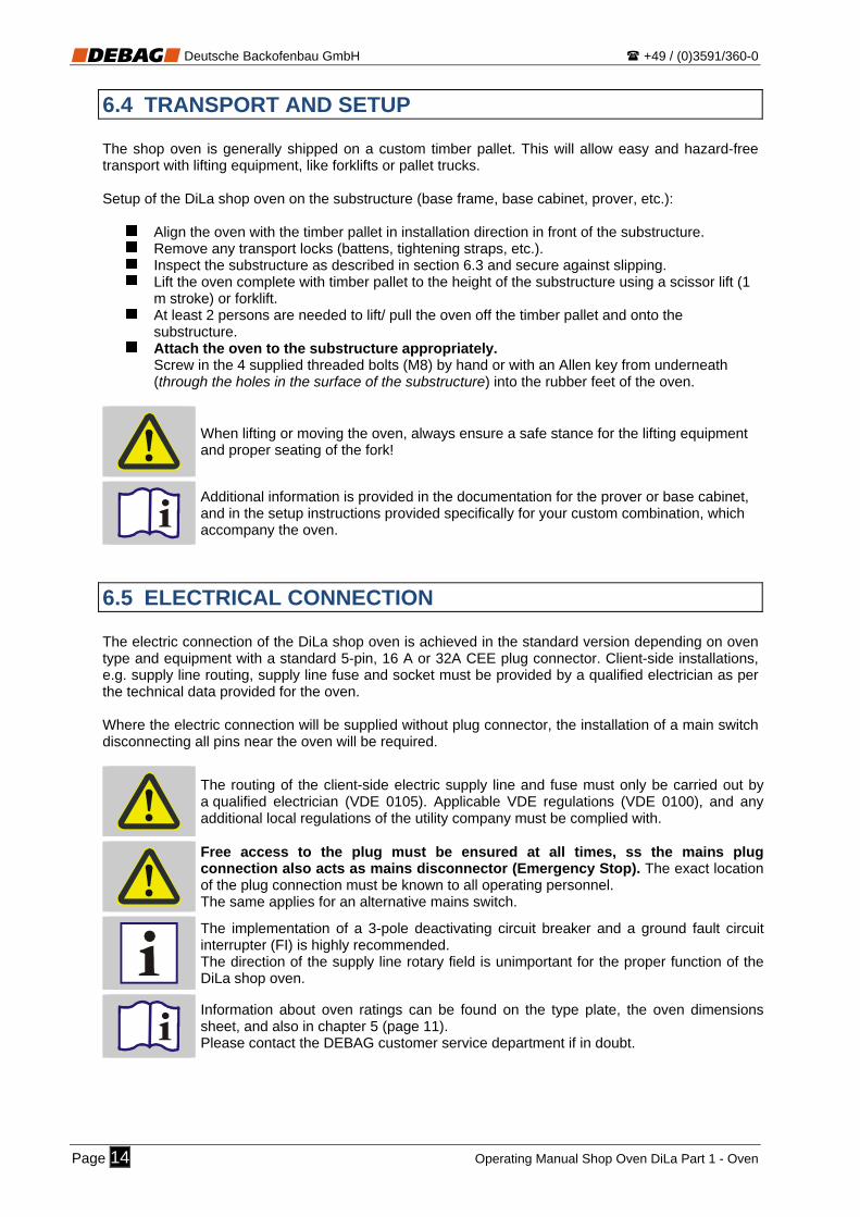
6.4 TRANSPORT AND SETUP The shop oven is generally shipped on a custom timber pallet. This will allow easy and hazard-free transport with lifting equipment, like forklifts or pallet trucks. Setup of the DiLa shop oven on the substructure (base frame, base cabinet, prover, etc.):
Align the oven with the timber pallet in installation direction in front of the substructure. Remove any transport locks (battens, tightening straps, etc.). Inspect the substructure as described in section 6.3 and secure against slipping. Lift the oven complete with timber pallet to the height of the substructure using a scissor lift (1
m stroke) or forklift. At least 2 persons are needed to lift/ pull the oven off the timber pallet and onto the
substructure. Attach the oven to the substructure appropriately.
Screw in the 4 supplied threaded bolts (M8) by hand or with an Allen key from underneath (through the holes in the surface of the substructure) into the rubber feet of the oven.
When lifting or moving the oven, always ensure a safe stance for the lifting equipment and proper seating of the fork!
Additional information is provided in the documentation for the prover or base cabinet, and in the setup instructions provided specifically for your custom combination, which accompany the oven.
6.5 ELECTRICAL CONNECTION The electric connection of the DiLa shop oven is achieved in the standard version depending on oven type and equipment with a standard 5-pin, 16 A or 32A CEE plug connector. Client-side installations, e.g. supply line routing, supply line fuse and socket must be provided by a qualified electrician as per the technical data provided for the oven. Where the electric connection will be supplied without plug connector, the installation of a main switch disconnecting all pins near the oven will be required.
The routing of the client-side electric supply line and fuse must only be carried out by a qualified electrician (VDE 0105). Applicable VDE regulations (VDE 0100), and any additional local regulations of the utility company must be complied with.
Free access to the plug must be ensured at all times, ss the mains plug connection also acts as mains disconnector (Emergency Stop). The exact location of the plug connection must be known to all operating personnel. The same applies for an alternative mains switch.
The implementation of a 3-pole deactivating circuit breaker and a ground fault circuit interrupter (FI) is highly recommended. The direction of the supply line rotary field is unimportant for the proper function of the DiLa shop oven.
Information about oven ratings can be found on the type plate, the oven dimensions sheet, and also in chapter 5 (page 11). Please contact the DEBAG customer service department if in doubt.
Page 14 Operating Manual Shop Oven DiLa Part 1 - Oven

Deutsche Backofenbau GmbH +49 / (0)3591/360-0
6.6 WATER CONNECTION 6.6.1 Ovens with fixed water connection A client-side R 3/4" cold water connection with appropriate shut off valve is required in the immediate vicinity (distance max. 1 m) of the installation location of the shop oven DiLa for its water connection. The connection is achieved by way of a pressure-safe and food-safe water connection hose (DIN DVGW certified), which forms part of the scope of delivery. The hose is connected to the water connection of the oven (see page 12). Water pressure at the connection point must be between 300 and 600 kPa (3 – 6 bar)! Pressures over 600 kPa will require the client-side installation of a pressure reducer. Only water with a hardness value between 1 - 5 dH must be used to keep lime scale build-up in the injection lines, the interior of the oven and the vaporiser (optional) to a minimum. In areas with greater water hardness values, the use of a suitable decalcification or filter system is mandatory.
To prevent possible water damage, the client-side shut-off valve must be closed outside of business hours.
For reasons of hygiene, only a connection to the public drinking water system is permitted. The required water quality must be maintained in order to prevent premature wear or damage to the oven.
Route the water connection hose in such a manner as to avoid any kinks in the hose or chafing on sharp edges. Select the distance between water connection and oven so that the hose will not be subjected to tensile stresses. In the case of integrated ovens, the hose length must also allow easy access for maintenance and service work (pulling out the oven).
Do not route the water hose directly along hot oven elements, e.g. the vapour exhaust pipe or vapour flap.
We recommend the use of an active charcoal filter system, e.g. BRITA Purity 300 for water recycling. This filter size will suffice for standard operation with the DiLa. In special cases, the exact filter size may have to be determined in terms of water consumption and local water quality. A complete decarbonisation of the drinking water should be avoided to prevent damage to the oven (bypass setting approx. 1 mm). Ideally, the BRITA filter system should be ordered with the new DiLa as an accessory from DEBAG. DEBAG customer service will also provide the installation, setting and annual maintenance of the filter system. Please consult your DEBAG consultant or contact the sales department for more information.
DEBAG will not accept warranty claims for oven damage, damage to accessory devices, or the deterioration of the quality of baked goods due to lime scale deposits (calcification).
Make sure to follow the corresponding operating instructions and especially the maintenance regulations when using a decalcification or filter system.
6.6.2 Ovens with Water Tank Ovens equipped with a water tank do not require a connection to the drinking water supply. Water is supplied via the water tank located in the base cabinet. P
lease read the separate operating manual supplied for the water tank.
Operating Manual Shop Oven DiLa Part 1 - Oven Page 15

Deutsche Backofenbau GmbH +49 / (0)3591/360-0
6.7 CONDENSATE DRAIN The condensate produced by the WSC (optional), external vaporiser (optional) and the vapour exhaust pipe during baking, is collected in the collection tank behind the oven, and must be fed into an appropriate container (bucket, etc.) or into a client-side drain (gully) via a hose (page 12).
Route the red condensate hoses leading from the hood, vapour flap and high-performance vaporiser through the openings in the floor of the oven all the way down into the collection tank. Push the hose down until it hits bottom, then withdraw it approx. 1 cm.
The condensate generated during the baking process may become very hot (up to 90 °C). You should therefore not empty the container during the baking process and avoid contact with the condensate - scalding hazard!
Check the fill level of the collection container before each baking program start. For reasons of hygiene, the container must be emptied at least 1x per day. It may be necessary to empty the collection container several times per day when baking with vaporisation, but may also be necessary when baking repeatedly without steam.
Where local conditions allow, the condensate should always be led off directly into a heat-resistant drain. Applicable regulations must be adhered to (syphon, ventilation section, etc.). Consult your authorised installer.
In the case of integrated ovens, the hose length must also allow easy access for maintenance and service work (pulling out the oven). Any reflux of the waste water from the client-side drain pipe into the collection container or oven must be prevented (ensure sufficient gradient and prevent backwater).
6.8 EXHAUST AIR
6.8.1 Ovens without vaporisation As the DiLa in this configuration bakes without additional vaporisation and the moist air escaping via the exhaust air flap (bake-off loss) will for the most part condensate inside the small condensation pipe, exhaust air can in this case generally be released into the ambient air without additional measures.
In special cases it will, however, be advisable to check whether an additional vapour exhaust pipe would be required. Consult your landlord and installer.
Page 16 Operating Manual Shop Oven DiLa Part 1 - Oven

Deutsche Backofenbau GmbH +49 / (0)3591/360-0
6.8.2 Ovens with vaporisation The humid exhaust air generated during baking in the DiLa with vaporiser must be led on the shortest route via a rust-proof, heat-resistant pipe (LW interior Ø 80, with steam hood LW interior Ø 150 (page 12)) into a chimney or directly to the outside of the building. The chimney must be condensate-resistant and must be equipped with a condensate drain.
The exhaust steam generated during baking must not be fed directly into the ambient air of the installation space of the oven without any additional measures!
When routing the exhaust pipe, the unhindered run-off of the condensate liquid must be ensured (permanent gradient). The individual pipe segments must be fitted into each other in flow direction to prevent any reflux of the condensate liquid. The pipe connections must be sealed with a heat-resistant sealant (silicon) as needed.
No uncontrolled steam (leaks, etc.) must escape from the oven or the exhaust steam system.
Due to a possible impairment of the baking quality, no external extractor fan or central extraction system must be connected to the exhaust steam connection. The use of a damper may be necessary.
6.8.3 Exhaust Steam Condenser (ESC) Where local conditions don't allow the exhaust steam to be led directly into the environment, and can also not be fed into a chimney, the oven can also be equipped with an ESC. The device functions on the principle of an air-cooled heat exchanger, and is completely integrated into the steam hood. Only dried room air exits from the output of the ESC. A further routing towards the outside of the building is not required. Function principle ESC:
incoming moist and hot exhaust air from baking chamber
dried and cooled air from ESC Hood fan
required ventilation clearance(cross hatched area)
above steam hood for cold ambient air supply
min
.30
cm
Store oven
Sufficient ventilation space (hashed area) above the oven is very important for the function of the ESC. This area must not be covered or blocked.
A later retrofit of an ESC is possible pending clarification of any structural abnormalities. Consult our customer service department.
Operating Manual Shop Oven DiLa Part 1 - Oven Page 17

Deutsche Backofenbau GmbH +49 / (0)3591/360-0
6.9 COMMISSIONING - INITIAL OPERATION Taking into consideration the information provided in the previous chapters, the oven must be set up properly and the connections to any optional accessory devices must be provided. Only now will the oven be ready for use.
Peel off the protective foil from all exterior panelling before heating the oven.
Specifically during the winter months it is important to make sure that when commissioning the cold oven in a warm and humid environment, no condensation remains on the oven. It is important to wait until the device temperature has reached ambient temperature. The internal safety temperature limiter could lock at temperatures below 0 °C. Wait until the oven has warmed up and the fault message on the oven clears.
Do not dispose of the protective film with household waste; recycle it instead.
The oven will be thoroughly cleaned and heated at the factory before delivery. It is, however, recommended to heat the oven without any baking goods in baking program 1 for approx. 2 hours at the time of commissioning. Any residual cleaning agents will be burned off completely during that time. This may cause some slight smell and possible smoke development.
Once the oven has been heated and subsequently cooled, thoroughly clean the interior of the baking chamber and the inside of the glass pane in the baking chamber door.
7 DECOMMISSIONING The following actions will be required if the DiLa shop oven will not be used for a foreseeable period of time (holidays, refurbishment, etc.):
Empty the oven completely.
Pull the mains plug from the wall socket or switch the client-side mains switch off (Position "OFF“, "AUS“ or "0“).
Close the client-side shut-off valve in the water supply line.
The settings stored in the oven controls will remain unchanged even if the mains supply is interrupted for an extended length of time.
Following an extended period of decommission, the oven must be heated, and all functions - particularly the vaporisation function - must be repeated several times without any baking goods. The baking chamber must then be thoroughly cleaned.
Final decommissioning and removal of the oven:
Ensure eco-friendly disposal. Comply with applicable national or regional regulations for waste disposal and recycling.
Page 18 Operating Manual Shop Oven DiLa Part 1 - Oven

Deutsche Backofenbau GmbH +49 / (0)3591/360-0
8 OVEN CONTROLLER
The DiLa shop oven can be equipped with one of two controller variants. PRO controller
• Film surface • LCD graphic display with RGB lighting • Shortstroke key
TOUCH controller
• Glass surface • 4.3“ TFT graphic display • Capacitive sensor buttons and slider
START button
Function keyF1
Door button
Navigation buttons
Function key F2
LCD display
Number pad
ON/OFF button Operation release sensor B
D C
A
ESC button
START button
Navigation buttons/ slider
TFT displayTouch operation
Door button
ON/OFF button Operation release button
ESC
B
D C
A
An exhaustive description of the oven controller can be found in the operating manual "Part 2 - PRO controller" or "Part 2 - TOUCH controller".
Operating Manual Shop Oven DiLa Part 1 - Oven Page 19

Deutsche Backofenbau GmbH +49 / (0)3591/360-0
9 STANDARD BAKING PROCESS The necessary operating actions on the DiLa shop oven are restricted to a minimum for standard baking operation. These include:
Switching the oven ON/ OFF
Selecting the relevant baking program and oven assignment
Loading the oven with raw dough
Starting the baking program
Removing the baked goods All operating tasks are additionally signalled both optically and acoustically (where possible).
An exhaustive description of all controller-specific operating actions can be found in the operating manual "Part 2 - Controller".
9.1 OPENING AND CLOSING THE BAKING CHAMBER DOOR
C The DiLa comes equipped with an electro-mechanical door lock.
The baking chamber door opens when the door button is pushed. The button lights up while the door is open. The door cannot be opened during vaporisation or while the cleaning program is running.
A scalding hazard may exist due to escaping steam when the oven door is opened.
Should the electro-mechanical door opening fail, simply press down on the door handle repeatedly and try pressing the door button again. In case of emergency the baking chamber door can also be opened by forcefully pulling on the emergency interlock release (placement see page 10).
Emergency opening: In case of emergency, the baking chamber door can be opened by forcefully pulling on the emergency interlock release.
Page 20 Operating Manual Shop Oven DiLa Part 1 - Oven

Deutsche Backofenbau GmbH +49 / (0)3591/360-0
9.2 BAKING START
Close the baking chamber door and press the ON/OFF button A to switch on the oven and start baking. The interior lighting, baking chamber fan and heater controller will switch on.
Inspect the exterior of the oven for any visible damage before starting a baking program! The oven must not be switched on if any defects are detected. The manager in charge must be notified immediately.
Some fault and information messages will only appear on the display once the oven has been switched on. The oven will only start functioning once these messages have been acknowledged.
A cold oven should be switched on at least 15 mins. prior to the scheduled baking start (30 mins. for ovens with high-performance vaporisation). Shorter heating times may result in an unsatisfactory initial baking result.
9.3 SELECT BAKING PROGRAM AND OVEN ASSIGNMENT The relevantly assigned baking program location and oven assignment for a specific product must be selected before baking.
Baking program selection is only available when the oven is switched on and no baking program has been initiated.
The selection of a new baking program should be done a few minutes before the scheduled program start so that the oven has sufficient time to adjust the required baking temperature. Only start the baking program after the oven displays "Ready" to avoid drawbacks in the quality of the finished baked goods.
Operating Manual Shop Oven DiLa Part 1 - Oven Page 21

Deutsche Backofenbau GmbH +49 / (0)3591/360-0
9.4 PREPARING THE RAW GOODS Depending on the dough to be used (pre-baked, fresh, deep frozen), the goods must be prepared in accordance with manufacturer instructions (thawed, proved, etc.) and placed onto the baking sheets before the actual baking process.
The products should be placed well apart on the baking sheet to achieve optimised browning. Manufacturer information regarding optimised sheet loads and arrangements must be complied with. Please contact the manufacturer of your raw dough goods or our master baker if you have any questions.
If the DiLa shop oven is equipped with a proving chamber as an accessory device, the proving of the raw dough will generally occur in an automatically controlled proving climate. The proving duration and the required climate will depend strongly on the condition of the raw goods, and must be specified and continuously monitored by the operating personnel.
Exhaustive descriptions can be found in the separate operating manual supplied for the prover.
9.5 LOADING THE RAW GOODS An acoustic signal will sound when the oven has reached the programmed starting temperature for the selected baking program. The Start button D will blink slowly. Only now will the oven be ready and can be loaded with raw goods.
Where the oven is installed in an area accessible to customers, the work area (approx. 1 m circumference around the front of the oven) must be cleared or secured appropriately (barrier tape or 2nd person), before the oven can be loaded (opening the baking chamber door). Extreme vigilance is required during this process.
A baking program can only be initiated when the oven is ready. You should therefore only load the oven once it is ready!
Pressing the door opening button C will open the baking chamber door.
The raw goods prepared on baking sheets must now be loaded into the oven, starting from
the bottom up. If the oven will not be fully loaded, the sheets should be distributed evenly in the chamber.
Close the baking chamber door and immediately press the START button D . Once the program has started, the START button will light up continuously.
The use of appropriate protective gloves when loading the oven is mandatory. A burn hazard exists in the area of the inner glass pane of the oven door, the entire baking chamber, and the baking sheets.
Page 22 Operating Manual Shop Oven DiLa Part 1 - Oven

Deutsche Backofenbau GmbH +49 / (0)3591/360-0
Distribute the raw goods evenly in the baking chamber when running the program with a reduced load. Specifically for DiLa 10, this will significantly impact baking quality.
The oven should be loaded as quickly as possible from the bottom up, and the baking chamber door closed quickly to avoid excessive heat loss.
Avoid impacting the baking sheets on the door seal to guarantee a proper sealing of the chamber for a long period of time.
9.6 BAKING Once the baking program has been initiated, all specified baking parameters will run automatically in sequence. The display will show the time remaining until the baking program is completed. No other operating actions are required.
A scalding hazard may exist due to escaping steam when the oven door is opened.
The baking chamber door cannot be opened during the vaporisation process.
The time remaining until the baking program is complete can be displayed with good visibility for customers if the oven is equipped with an LED display "Remaining baking time" (optional).
9.7 REMOVING THE BAKED GOODS Once the baking time has elapsed, the baking chamber door will open automatically (optional setting) and will remain in ventilation position (gap). The door opening button C will blink.
Pressing the door opening button C will end the baking program. The baking chamber door is released and can now be opened completely from the ventilation position.
The baking sheets with the finished baked goods can now be removed. The sheets should
now be loaded into (optional) racks to cool down for approx. 5 mins. Once cooled, the goods can now be loaded directly into the shelves or baskets, etc.
The baking chamber door should be closed as soon as possible, once all baking sheets
have been removed.
Another baking program or oven assignment can now be selected for the next baking process as needed. The oven will be ready to bake after a short re-heating period of approx. 3 mins.
Operating Manual Shop Oven DiLa Part 1 - Oven Page 23

Deutsche Backofenbau GmbH +49 / (0)3591/360-0
The use of appropriate protective gloves when unloading the oven is mandatory. A burn hazard exists in the area of the inner glass pane of the oven door, the entire baking chamber, and the baking sheets.
After removal of the baked goods, the baking chamber door should be closed as soon as possible to avoid excessive heat loss.
If preferred, the baking chamber door can also be set to remain closed at the end of the baking time (oven setting). In that case, the post-baking function can be utilised at the end of the baking time.
9.8 END OF BAKING
The oven will have to be switched off manually via the ON/OFF button A after the last baking process has been completed.
In ovens with a fixed water connection, the client-side shut-off valve in the water supply line
must be closed.
Remove all baked goods from the baking chamber.
Carry out the daily cleaning routine according to instructions after the oven has cooled down.
A burn hazard will still exist inside the baking chamber after the shop oven has been switched off (temperatures above 100 °C).
The oven is to be emptied completely at the end of daily operation. For reasons of fire safety, no baked goods must be left unattended inside the oven (for drying, etc.).
The convection fan will continue to run if the baking chamber temperature is still above 210 °C after the oven has been switched off, and will continue to run until the lower temperature limit has been reached.
Page 24 Operating Manual Shop Oven DiLa Part 1 - Oven

Deutsche Backofenbau GmbH +49 / (0)3591/360-0
10 CLEANING Compliance with the cleaning instructions provided here is important in order to maintain functional reliability and optical appearance of the DiLa shop oven for a long period of time. The cleaning tasks to be performed daily are:
Wiping the entire front of the oven, including the front film or glass surface of the operating panel with a damp (not wet) cloth without any abrasive cleaning agents.
Wiping the rubber door seal with a damp cloth without any abrasive cleaning agents.
Removal of any baked goods residue, specifically aggressive salt and base residue with a
heat-resistant cleaning brush and a wooden spatula in case of burned in debris.
Cleaning of the oven interior, specifically the floor, the baking sheet supports, the rear wall and inner glass pane of the baking chamber door with a commercially available, food-safe oven cleaner.
Cleaning of the used baking sheets, and subsequent spraying with a separating agent for
baking trays as needed.
Emptying the condensate liquid collection container in ovens with vaporiser. Check the container intermittently if several baking processes are completed each day.
Perform the following cleaning tasks at least once a week:
Thorough cleaning of the baking chamber interior, specifically the side walls after removing the baking sheet supports (see chapter 10.1 – page 26) with a commercially available, food-safe oven cleaner.
Thorough cleaning of the baking sheet supports outside the oven with a commercially
available, food-safe oven cleaner.
Cleaning the space in between the glass panes (see chapter 10.2 – page 26) of the baking chamber door after opening out the interior pane; use commercially available glass cleaner.
A burn hazard will still exist inside the baking chamber after the shop oven has been switched off (temperatures above 100 °C). The oven must therefore only be cleaned after the baking chamber has sufficiently cooled.
The oven must only be cleaned after mains power has been deactivated. Pull the mains plug before commencing work or switch off the mains switch.
No caustic, abrasive or foodstuff-incompatible cleaning agents or solvents must be used. The oven must not be cleaned with a high-pressure cleaner or similar device, or with excessive amounts of water.
Do not touch the halogen lamps of the oven lighting when cleaning the space between the glass panes of the baking chamber door. Doing so might lead to an early lamp failure.
See separate operating manual for EasyClean (optional).
Operating Manual Shop Oven DiLa Part 1 - Oven Page 25

Deutsche Backofenbau GmbH +49 / (0)3591/360-0
Page 26 Operating Manual Shop Oven DiLa Part 1 - Oven
10.1 REMOVING THE BAKING SHEET SUPPORTS
Lift the baking sheet supports out of their holders and remove.
1. 2.
Reverse the process to replace the supports. The structural design will make an accidental swap of the left and right supports impossible (different hole distances).
The oven must only be operated with the supports firmly in place.
The baking sheet supports must only be removed after the mains connection of the oven has been deactivated and the oven has cooled sufficiently. Pull the mains plug before commencing work or switch off the mains switch.
10.2 OPENING THE INTERNAL GLASS PANE OF THE BAKING CHAMBER DOOR
Open the baking chamber door. Pull simultaneously on the two opening flaps until the
magnetic lock releases.
Tilt the inner pane back into place to close. Make sure that none of the lighting cables do not get cinched.
Note: The inner door is additionally held by a strap hinge and cannot fall out. Make sure to avoid direct contact with the halogen lamps while the inner glass pane is open.

Deutsche Backofenbau GmbH +49 / (0)3591/360-0
11 OVEN MAINTENANCE We recommend having the oven and any accessory devices (prover, water tank, etc.) serviced by our expert technicians at least once a year to maintain operational safety and continuous availability of your DiLa shop oven. An automatic maintenance reminder message can be set on request.
Maintenance work must only be carried out after the mains power supply for the oven has been deactivated and the oven has cooled down sufficiently. Pull the mains plug before commencing work or switch off the mains switch.
We urgently draw attention to the fact that repairs on the electronics, heater and temperature limiter, as well as on any other safety devices must only be performed by authorised and trained personnel of the manufacturer.
DEBAG offers oven-specific maintenance contracts as an additional service. Please contact the DEBAG customer service department.
Any damage caused by inadequate or faulty maintenance shall result in the warranty becoming void. Chapter 3.5 (page 10)
11.1 REPLACING A FAULTY OVEN LAMP The replacement of faulty baking chamber lighting can be carried out by the operating personnel or another trianed member of staff.
Open the interior glass pane of the baking chamber door as described in chapter 10.2 (page 26).
Carefully remove the defective lamp by gently pulling it from its base.
Insert the new halogen lamp (original DEBAG spare part) into the base without coming into direct skin contact with the glass bulb.
Close the inner glass pane of the baking chamber door.
A burn hazard will still exist inside the baking chamber after the shop oven has been switched off (temperatures above 100 °C). Bulb changes must therefore only be carried out after the baking chamber has sufficiently cooled.
A faulty lamp must only be replaced when the oven is switched off. Pull the mains plug before commencing work or switch off the mains switch.
Avoid direct skin contact with the glass bulb of the halogen lamp. Doing so might lead to an early lamp failure.
Only use original spare part bulbs with the correct technical parameters. The use of halogen bulbs with inappropriate wattage or voltage may result in the failure of the electronic controller!
Operating Manual Shop Oven DiLa Part 1 - Oven Page 27

Deutsche Backofenbau GmbH +49 / (0)3591/360-0
12 FAULTS AND ERROR MESSAGES Oven faults and critical states are shown as error messages on the display.
Please contact our customer service department if the troubleshooting tips provided do not remedy the fault, or if errors occur frequently!
Our service numbers (available also outside regular business hours) can be found on the service decal attached to the oven, or call our central switchboard (the number can be found on the reverse of the cover page of this operating manual).
12.1 NON-RESETTABLE FAULTS
A continuation of the baking process will not be possible after one of these faults. The fault will first have to be remedied.
Description in the operating manual "Part 2 – Controller“.
12.2 RESETTABLE FAULTS
A continuation of the baking process will be possible after one of these faults.
Description in the operating manual "Part 2 – Controller“.
Page 28 Operating Manual Shop Oven DiLa Part 1 - Oven

Deutsche Backofenbau GmbH +49 / (0)3591/360-0
13 APPENDIX: LED REMAINING BAKING TIME DISPLAY A large red "Remaining baking time" display can be optionally integrated into the extractor hood of your DiLa shop oven. This will allow your customers to see at a distance, when freshly baked goods will be available.
20
The following information will be displayed:
The LED display will be dark when the oven is switched off.
Blinking of the two horizontal bars signals the heating process prior to baking or between two baking processes.
The oven will not be ready at that time
When the oven is switched on and the baking timer has not yet been activated, then only the two horizontal bars will be blinking in the display.
"Oven ready" is signalled with the two bars lighting continuously.
Once the baking program has been initiated, the remaining baking time will be shown in the display.
Twin ovens (see page 31) come equipped with two remaining baking time displays in the hood. The display on the left represents the top oven, and the display on the right the bottom one.
Operating Manual Shop Oven DiLa Part 1 - Oven Page 29

Deutsche Backofenbau GmbH +49 / (0)3591/360-0
Page 30 Operating Manual Shop Oven DiLa Part 1 - Oven

Deutsche Backofenbau GmbH +49 / (0)3591/360-0
14 APPENDIX: TWIN OVENS The so-called twin ovens are a popular type variation of DiLa shop ovens. Two independently functioning DiLa shop ovens are positioned one on top of the other. The main benefit of twin ovens is their flexibility and greater baking area with a reduced device footprint. Various synchronisation functions have been integrated in the DiLa controller to facilitate the operation of twin ovens.
14.1 INSTRUCTIONS BEFORE COMMISSIONING Transport and Setup: The transport and setup of a DiLa twin oven is principally the same as for a single oven and is described in detail in chapter 6.4 (page 14).
It is important to note during setup, which oven has been designated top and which bottom oven. This will be apparent either by the pre-installed hood (top oven) or the vapour flap (the vapour flap for the bottom oven will have a condensate liquid drain).
For the purpose of centring and to prevent slippage, the top DiLa shop oven must be affixed to the bottom oven via the threaded bolts that are screwed into the rubber feet of the top oven from underneath the top of the bottom oven.
Connection: Since the DiLa twin oven consists of two individual ovens on top of each other, they will each need a mains and water connection (as for the single oven). The exhaust steam and condensate for both ovens is connected, which means that only one exhaust air and waste water connection will be required.
In order to allow data exchange (synchronisation) between the two ovens, they must be additionally connected via a data cable. Relevant synchronisation jacks (SYNCH) 1 are located on the rear wall of both ovens. Connect the SYNCH jack of the top oven with the SYNCH jack of the bottom oven (patch cable).
Synchronisation jack:
1
1
Attach the synchronisation cable so that it does not come into contact with hot surfaces (steam
ipe, exhaust flap, etc.). p
Operating Manual Shop Oven DiLa Part 1 - Oven Page 31

Deutsche Backofenbau GmbH +49 / (0)3591/360-0
14.2 NOTES ON INSTRUCTIONS The data communication between the two ovens will provide access to the following additional functions:
Using the operating release button on one oven will automatically release operation on the second oven, once the oven is switched on.
Any modifications to a baking program on one oven will be applied to the second oven either manually or automatically (depending on setting).
Additional information about twin ovens can be found in the operating manual "Part 2 - Controller".
Additional Notes:
Both ovens must be connected to mains electricity for the data communication to work. The functionality is not dependent on whether the oven is switched on or off.
Only modify baking programs with active baking program synchronisation if no baking program is currently running on either of the ovens.
Remember during cleaning and repair work that each of the ovens has an own mains electricity and water supply line, and that both mains plugs must be disconnected in order to have both ovens voltage-free.
Page 32 Operating Manual Shop Oven DiLa Part 1 - Oven

Deutsche Backofenbau GmbH +49 / (0)3591/360-0
15 APPENDIX: DILA D DiLa ovens of type "D" come equipped with a transparent glass rear panel (fixed door) due to a modified baking chamber construction; this rear door can only be opened for cleaning and service purposes. The customer has a clear view of the baking process via the transparent rear wall, which can be an attractive advertising feature, specifically where the oven is integrated into a sales counter. Structure DiLa 5 D:
Operating side Customer side
Emergency interlock release for
operator-side door
Emergency interlock release for
customer-side door
Drainage hoses 3/4" for
condensate
Door 2 - Glass rear wall(only to be opened for cleaning) Door 1 - Front
Over-temperature
limiter
Mains supply line with CEE plug(approx. 3 m)
15.1 OPENING AND CLEANING OF THE GLASS REAR WALL The glass rear wall must be cleaned at the same time as the glass panes in the operating door.
Make sure to read and familiarise yourself with the safety instructions and requirements provided in chapter 10 (page 25) before starting your cleaning tasks.
With the oven switched off, select the menu function "Open door 2".
Additional information about D ovens can be found in the operating manual "Part 2 - Controller".
Operating Manual Shop Oven DiLa Part 1 - Oven Page 33
Deutsche Backofenbau GmbH +49 / (0)3591/360-0
Page 34 Operating Manual Shop Oven DiLa Part 1 - Oven

Deutsche Backofenbau GmbH +49 / (0)3591/360-0
16 APPENDIX: DILA B DiLa ovens of type "B" come equipped with an additional glass door on the back of the oven for removing finished baked goods. This will allow the loading of the oven in the prep room, while the finished baked goods can then be unloaded in the sales area. Structure DiLa 5 B:
Operating side Customer side
Mains supply line with CEE plug(approx. 3 m)
Emergency interlock release for
operator-side door
Emergency interlock release for customer-
side door
Door 2 opening button(with LED lighting)
Drainage hoses 3/4" for condensate
Door 2 - Rear(only suitable for baking off) Door 1 - Front
Over-temperature
limiter
R
16.1 SPECIFICS OF OVEN OPERATION
Door 2 on the customer side can be opened in practically any operating situation by pressing the button R .
Depending on oven setting, the door on the operating or customer side will open to ventilation position at the end of the baking time, and the LED lighting of the door button R will blink. With the press of a button R , the door on the customer side is released for full opening, and the baking program is ended.
16.2 CLEANING 2ND BAKING CHAMBER DOOR The glass rear door facing the customers (2) must be cleaned at the same time as the glass panes in the operating door (1).
Make sure to read and familiarise yourself with the safety instructions and requirements provided in chapter 10 (page 25) before starting your cleaning tasks.
Operating Manual Shop Oven DiLa Part 1 - Oven Page 35

Deutsche Backofenbau GmbH +49 / (0)3591/360-0
Page 36 Operating Manual Shop Oven DiLa Part 1 - Oven

Deutsche Backofenbau GmbH +49 / (0)3591/360-0
17 APPENDIX: EASYCLEAN Your DiLa shop oven can be optionally equipped with the fully automated cleaning system EasyClean.
The instructions for the cleaning system can be found in the following documents
Operating manual "Part 3 - EasyClean" (Item No.: 9124996) incl. safety data sheet "CleanFixx - oven cleaner"
Quick start guide "EasyClean" These documents will be provided at the time of delivery of relevantly equipped ovens.
Make sure to comply with the instructions and requirements included in the above documents when using the EasyClean II cleaning system and when handling the DEBAG CleanFixx oven cleaner.
Operating Manual Shop Oven DiLa Part 1 - Oven Page 37

Deutsche Backofenbau GmbH +49 / (0)3591/360-0
Page 38 Operating Manual Shop Oven DiLa Part 1 - Oven

Deutsche Backofenbau GmbH +49 / (0)3591/360-0
18 APPENDIX: LOADING TROLLEY The DiLa comes equipped with fixed baking sheet supports as standard, which are only removed for cleaning. The oven can optionally be equipped with a semi-automatic loader. In that case, all baking sheets are loaded into and unloaded from the oven on a baking rack in a single work step. A loading trolley is used for transporting and guiding of the baking rack.
Where the oven is installed in an area accessible to customers, the work area (approx. 1 m circumference around the front of the oven) must be cleared or secured appropriately (barrier tape or 2nd person), before the oven can be loaded (opening the baking chamber door). Extreme vigilance is required during this process.
The instructions for the cleaning system can be found in the following documents:
Quick start guide "Loading Trolley" - A3 laminated (Item No.: 9122969)
These documents will be provided at the time of delivery of relevantly equipped ovens.
Make sure to comply with the instructions and requirements included in the above documents when using the loading system.
The use of appropriate protective gloves when unloading the loading trolley is mandatory. A burn hazard exists in the area of the inner glass pane of the oven door, the entire baking chamber, and the loading trolley.
Always use the guide rod supplied when inserting or removing the baking rack into/out of the oven.
The loading trolley must be pushed slowly over straight, level and smooth floors without any major bumps. The panel doors must be closed during transport. Hold the trolley securely on the two lateral recessed grips. Passing over obstacles (e.g. thresholds) or objects, and any fast movement is strictly forbidden - danger of toppling!
Operating Manual Shop Oven DiLa Part 1 - Oven Page 39

Deutsche Backofenbau GmbH +49 / (0)3591/360-0
Page 40 Operating Manual Shop Oven DiLa Part 1 - Oven

Deutsche Backofenbau GmbH +49 / (0)3591/360-0
Operating Manual Shop Oven DiLa Part 1 - Oven Page 41
19 APPENDIX: DECLARATION OF CONFORMITY
EC Declaration of Conformity In the sense of the EC Machine Directive 2006/42/EC dated Dec. 12, 2002, Appensix II A
Manufacturer DEBAG Deutsche Backofenbau GmbH Dresdener Strasse 88 02625 Bautzen, Germany Tel.: +49 (0) 3591 360-0 Fax: +49 (0) 3591 360-140
We hereby declare that the machine designated below in its concept and design as well as in the version introduced by us, corresponds to the principle safety and health regulations of the provisions and directives listed. This declaration becomes invalid if changes not approved by us are made to the product.
Machine Description Make: Shop oven DiLa Types: DiLa 5 DiLa 10 DiLa 5+5 DiLa 10+5 and offered optional accessory devices
EC Directives 2006/42/EC
Machine Directive 2004/108/EC
EMC Directive
Applied Harmonised Standards
EN 60335-1:2010 Safety of electric appliances for household and similar use - Part 1: General requirements
EN 60335-2-36:2008 Safety of electric appliances for household and similar use - Part 2-36: Special requirements for electric cookers, fry and baking ovens, and hot plates for commercial use
EN 60335-2-42:2009 Safety of electric appliances for household and similar use - Part 2-42: Special requirements for electric convection ovens, steam cookers and steam-convection ovens for commercial use
EN ISO 12100-1:2003/A1:2009 Safety of machinery - basic terminology - Part 1: Basic terminology
EN ISO 12100-2:2003/A1:2009 Safety of machinery - basic terminology - Part 2: Technical principles
Person authorised to compile technical documentation
Thomas Zabel, DEBAG Konstruktion, 02625 Bautzen, Dresdener Str. 88
Bautzen, May 5, 2011
J.Straube R.Kiesl Managing Director Construction Manager