Embed Size (px)
Citation preview

Language version: USEdition: 2010-03
Order number: 5780200384From vehicle ID No: TL02100101>
Original operating instructions
tl210
OPERATING INSTRUCTIONS
tl210
Whe
el L
oade
r
Wheel Loader

Please complete before commissioning the wheel loader:
Vehicle model: .........................................................................................
Vehicle ID-No: .........................................................................................
Year of construction: ........................................................................................
Commissioned on: .........................................................................................
Dealer:
This Operating Manual is protected by limited copyright. It may be reproduced for and used by the driver/ plant operator.
®

TL210
Table of Contents
01_Table of Contents_enIVZ.fm - V 0.1 - 12.5.11 1 / 180
1
4
1 Table of Contents
1 Table of Contents . . . . . . . . . . . . . . . . . . . . . . . . . . . . . . . . . . . . . . . . . . 12 Introduction . . . . . . . . . . . . . . . . . . . . . . . . . . . . . . . . . . . . . . . . . . . . . . . 5
2.1 Concerning these operating instructions . . . . . . . . . . . . . . . . . 52.2 Notes on using the operating manual . . . . . . . . . . . . . . . . . . . . 72.3 Intended use. . . . . . . . . . . . . . . . . . . . . . . . . . . . . . . . . . . . . . . . . 72.4 Unintended use . . . . . . . . . . . . . . . . . . . . . . . . . . . . . . . . . . . . . . 72.5 Warranty . . . . . . . . . . . . . . . . . . . . . . . . . . . . . . . . . . . . . . . . . . . . 72.6 Declaration of Conformity. . . . . . . . . . . . . . . . . . . . . . . . . . . . . . 82.7 Product Identifikation Number (PIN) plate . . . . . . . . . . . . . . . 10
3 Safety . . . . . . . . . . . . . . . . . . . . . . . . . . . . . . . . . . . . . . . . . . . . . . . . . . . 113.1 General safety notes . . . . . . . . . . . . . . . . . . . . . . . . . . . . . . . . . 113.1.1 Safety symbol . . . . . . . . . . . . . . . . . . . . . . . . . . . . . . . . . . . . . . . 113.1.2 Hazard Classification . . . . . . . . . . . . . . . . . . . . . . . . . . . . . . . . . . 113.1.3 Descriptions of hazard pictorials . . . . . . . . . . . . . . . . . . . . . . . . . 12
3.2 Location of safety signs . . . . . . . . . . . . . . . . . . . . . . . . . . . . . . 133.2.1 Symbols/Pictograms . . . . . . . . . . . . . . . . . . . . . . . . . . . . . . . . . . 14
3.3 Personal safety . . . . . . . . . . . . . . . . . . . . . . . . . . . . . . . . . . . . . 173.3.1 Personal safety gear . . . . . . . . . . . . . . . . . . . . . . . . . . . . . . . . . . 17
3.4 Work zone safety . . . . . . . . . . . . . . . . . . . . . . . . . . . . . . . . . . . . 183.4.1 General work zone regulations and safe work practices . . . . . . . 183.4.2 Deactivation and protection against re-activation . . . . . . . . . . . . 18
3.5 General safety notes . . . . . . . . . . . . . . . . . . . . . . . . . . . . . . . . . 193.6 Operation . . . . . . . . . . . . . . . . . . . . . . . . . . . . . . . . . . . . . . . . . . 203.7 Hazard zone . . . . . . . . . . . . . . . . . . . . . . . . . . . . . . . . . . . . . . . . 203.8 Transporting persons . . . . . . . . . . . . . . . . . . . . . . . . . . . . . . . . 203.9 Stability. . . . . . . . . . . . . . . . . . . . . . . . . . . . . . . . . . . . . . . . . . . . 213.9.1 Stability on sloping ground. . . . . . . . . . . . . . . . . . . . . . . . . . . . . . 21
3.10 Driving . . . . . . . . . . . . . . . . . . . . . . . . . . . . . . . . . . . . . . . . . . . . 223.11 Working Operation . . . . . . . . . . . . . . . . . . . . . . . . . . . . . . . . . . 223.12 Guides. . . . . . . . . . . . . . . . . . . . . . . . . . . . . . . . . . . . . . . . . . . . . 233.13 Use under the danger of falling objects . . . . . . . . . . . . . . . . . 233.14 Working in the vicinity of underground power lines . . . . . . . 233.15 Working in the vicinity of overhead power lines . . . . . . . . . . 24
TL210
Table of Contents
2 / 180
1
01_Table of Contents_enIVZ.fm - V 0.1 - 12.5.11
4
3.16 Operation in closed spaces . . . . . . . . . . . . . . . . . . . . . . . . . . . .253.17 Work stoppages . . . . . . . . . . . . . . . . . . . . . . . . . . . . . . . . . . . . .253.18 Load hook applications . . . . . . . . . . . . . . . . . . . . . . . . . . . . . . .263.19 Conversions, maintenance and repairs . . . . . . . . . . . . . . . . . .273.20 Recovery, loading and transporting . . . . . . . . . . . . . . . . . . . . .293.21 Monitoring and inspections . . . . . . . . . . . . . . . . . . . . . . . . . . . .293.22 Fire prevention . . . . . . . . . . . . . . . . . . . . . . . . . . . . . . . . . . . . . .303.23 Emergency exit . . . . . . . . . . . . . . . . . . . . . . . . . . . . . . . . . . . . . .303.24 Notes concerning residual dangers . . . . . . . . . . . . . . . . . . . . .303.24.1 Failure of hydraulic system . . . . . . . . . . . . . . . . . . . . . . . . . . . . . .30
4 Initial installation and adjustments . . . . . . . . . . . . . . . . . . . . . . . . . . . .314.1 Initial familiarization . . . . . . . . . . . . . . . . . . . . . . . . . . . . . . . . . .314.1.1 Handing over the machine and instructing the operator . . . . . . . .31
5 Description of the Wheel Loader . . . . . . . . . . . . . . . . . . . . . . . . . . . . . .335.1 Overview of wheel loader. . . . . . . . . . . . . . . . . . . . . . . . . . . . . .335.1.1 Overview filters . . . . . . . . . . . . . . . . . . . . . . . . . . . . . . . . . . . . . . .34
5.2 Display elements and operating controls in operator's stand355.2.1 Operating controls. . . . . . . . . . . . . . . . . . . . . . . . . . . . . . . . . . . . .355.2.2 Front control console . . . . . . . . . . . . . . . . . . . . . . . . . . . . . . . . . .365.2.3 Lateral control console . . . . . . . . . . . . . . . . . . . . . . . . . . . . . . . . .375.2.4 Control unit heating / Klimatronic . . . . . . . . . . . . . . . . . . . . . . . . .385.2.5 Display . . . . . . . . . . . . . . . . . . . . . . . . . . . . . . . . . . . . . . . . . . . . .395.2.6 Fuse and relay box . . . . . . . . . . . . . . . . . . . . . . . . . . . . . . . . . . . .405.2.7 Driver's seat . . . . . . . . . . . . . . . . . . . . . . . . . . . . . . . . . . . . . . . . .43
6 Maintenance . . . . . . . . . . . . . . . . . . . . . . . . . . . . . . . . . . . . . . . . . . . . . .456.1 General. . . . . . . . . . . . . . . . . . . . . . . . . . . . . . . . . . . . . . . . . . . . .456.2 Care and cleaning . . . . . . . . . . . . . . . . . . . . . . . . . . . . . . . . . . . .456.3 Inspection intervals . . . . . . . . . . . . . . . . . . . . . . . . . . . . . . . . . .466.3.1 Regular oil analysis. . . . . . . . . . . . . . . . . . . . . . . . . . . . . . . . . . . .476.3.2 Warranty . . . . . . . . . . . . . . . . . . . . . . . . . . . . . . . . . . . . . . . . . . . .48
6.4 Inspection means . . . . . . . . . . . . . . . . . . . . . . . . . . . . . . . . . . . .496.4.1 Service parts . . . . . . . . . . . . . . . . . . . . . . . . . . . . . . . . . . . . . . . . .496.4.2 Consumables . . . . . . . . . . . . . . . . . . . . . . . . . . . . . . . . . . . . . . . .50
6.5 Lubrication . . . . . . . . . . . . . . . . . . . . . . . . . . . . . . . . . . . . . . . . .556.5.1 Lubrication plan. . . . . . . . . . . . . . . . . . . . . . . . . . . . . . . . . . . . . . .56
6.6 Maintenance and Inspection Plan . . . . . . . . . . . . . . . . . . . . . . .596.6.1 Daily tasks. . . . . . . . . . . . . . . . . . . . . . . . . . . . . . . . . . . . . . . . . . .596.6.2 Tasks to be performed weekly . . . . . . . . . . . . . . . . . . . . . . . . . . .60

TL210
Table of Contents
01_Table of Contents_enIVZ.fm - V 0.1 - 12.5.11 3 / 180
1
4
6.6.3 Inspection plan machine . . . . . . . . . . . . . . . . . . . . . . . . . . . . . . . 61
6.7 Maintenance and inspection work . . . . . . . . . . . . . . . . . . . . . . 646.7.1 Display . . . . . . . . . . . . . . . . . . . . . . . . . . . . . . . . . . . . . . . . . . . . . 656.7.2 Engine . . . . . . . . . . . . . . . . . . . . . . . . . . . . . . . . . . . . . . . . . . . . . 666.7.3 Engine - cooling system. . . . . . . . . . . . . . . . . . . . . . . . . . . . . . . . 696.7.4 Air intake system . . . . . . . . . . . . . . . . . . . . . . . . . . . . . . . . . . . . . 756.7.5 Fuel system . . . . . . . . . . . . . . . . . . . . . . . . . . . . . . . . . . . . . . . . . 806.7.6 V-belt . . . . . . . . . . . . . . . . . . . . . . . . . . . . . . . . . . . . . . . . . . . . . . 846.7.7 Hydraulic oil tank . . . . . . . . . . . . . . . . . . . . . . . . . . . . . . . . . . . . . 866.7.8 Hydraulic oil suction filter . . . . . . . . . . . . . . . . . . . . . . . . . . . . . . . 896.7.9 Hydraulic oil return filter . . . . . . . . . . . . . . . . . . . . . . . . . . . . . . . . 916.7.10 Axles . . . . . . . . . . . . . . . . . . . . . . . . . . . . . . . . . . . . . . . . . . . . . . 936.7.11 Wheels. . . . . . . . . . . . . . . . . . . . . . . . . . . . . . . . . . . . . . . . . . . . . 996.7.12 Electrical equipment . . . . . . . . . . . . . . . . . . . . . . . . . . . . . . . . . 1006.7.13 Cab ventilation dust filter . . . . . . . . . . . . . . . . . . . . . . . . . . . . . . 1036.7.14 Windshield washer system . . . . . . . . . . . . . . . . . . . . . . . . . . . . 105
6.8 Taking out of service. . . . . . . . . . . . . . . . . . . . . . . . . . . . . . . . 1066.8.1 Preservation (temporary immobilization ) . . . . . . . . . . . . . . . . . 1066.8.2 While being taken out of service . . . . . . . . . . . . . . . . . . . . . . . . 1076.8.3 After the machine had been taken out of service . . . . . . . . . . . 1076.8.4 Disposal . . . . . . . . . . . . . . . . . . . . . . . . . . . . . . . . . . . . . . . . . . . 107
7 Operation . . . . . . . . . . . . . . . . . . . . . . . . . . . . . . . . . . . . . . . . . . . . . . . 1097.1 Before operation . . . . . . . . . . . . . . . . . . . . . . . . . . . . . . . . . . . 1097.1.1 Adjustments . . . . . . . . . . . . . . . . . . . . . . . . . . . . . . . . . . . . . . . . 110
7.2 Operation . . . . . . . . . . . . . . . . . . . . . . . . . . . . . . . . . . . . . . . . . 1157.2.1 Monitoring the machine during operation . . . . . . . . . . . . . . . . . 1217.2.2 Driving, steering and braking . . . . . . . . . . . . . . . . . . . . . . . . . . . 1227.2.3 Working operation . . . . . . . . . . . . . . . . . . . . . . . . . . . . . . . . . . . 1327.2.4 Changing work attachments . . . . . . . . . . . . . . . . . . . . . . . . . . . 1377.2.5 Loading, grading, excavating. . . . . . . . . . . . . . . . . . . . . . . . . . . 1397.2.6 Ride control system (RCS) (option) . . . . . . . . . . . . . . . . . . . . . . 1417.2.7 Hydroinflation of tires . . . . . . . . . . . . . . . . . . . . . . . . . . . . . . . . . 1437.2.8 Notes for winter operation . . . . . . . . . . . . . . . . . . . . . . . . . . . . . 144
8 Transportation . . . . . . . . . . . . . . . . . . . . . . . . . . . . . . . . . . . . . . . . . . . 1458.1 Recovering the wheel loader . . . . . . . . . . . . . . . . . . . . . . . . . 1458.2 Lifting with a crane . . . . . . . . . . . . . . . . . . . . . . . . . . . . . . . . . 1498.3 Transport . . . . . . . . . . . . . . . . . . . . . . . . . . . . . . . . . . . . . . . . . 150
9 Specifications . . . . . . . . . . . . . . . . . . . . . . . . . . . . . . . . . . . . . . . . . . . 151

TL210
Table of Contents
4 / 180
1
01_Table of Contents_enIVZ.fm - V 0.1 - 12.5.11
4
9.1 Views . . . . . . . . . . . . . . . . . . . . . . . . . . . . . . . . . . . . . . . . . . . . .1519.1.1 Dimensioned drawing with bucket, directly mounted . . . . . . . . .1519.1.2 Dimensioned drawing with bucket and quick-attach system. . . .152
9.2 Technical data . . . . . . . . . . . . . . . . . . . . . . . . . . . . . . . . . . . . . .1539.2.1 Engine. . . . . . . . . . . . . . . . . . . . . . . . . . . . . . . . . . . . . . . . . . . . .1539.2.2 Electrical system . . . . . . . . . . . . . . . . . . . . . . . . . . . . . . . . . . . . .1549.2.3 Travel drive . . . . . . . . . . . . . . . . . . . . . . . . . . . . . . . . . . . . . . . . .1549.2.4 Brakes. . . . . . . . . . . . . . . . . . . . . . . . . . . . . . . . . . . . . . . . . . . . .1559.2.5 Hydraulics . . . . . . . . . . . . . . . . . . . . . . . . . . . . . . . . . . . . . . . . . .1569.2.6 Permissible loads in compliance with German Road Traffic Regulations (StVZO)1579.2.7 Sound level values, vibration . . . . . . . . . . . . . . . . . . . . . . . . . . .157
9.3 Dimensions and weights . . . . . . . . . . . . . . . . . . . . . . . . . . . . .1589.3.1 Cab . . . . . . . . . . . . . . . . . . . . . . . . . . . . . . . . . . . . . . . . . . . . . . .1619.3.2 Pressure chart. . . . . . . . . . . . . . . . . . . . . . . . . . . . . . . . . . . . . . .1629.3.3 Optional accessories. . . . . . . . . . . . . . . . . . . . . . . . . . . . . . . . . .163
10 Troubleshooting . . . . . . . . . . . . . . . . . . . . . . . . . . . . . . . . . . . . . . . . . .16510.1 Who is allowed to rectify malfunctions? . . . . . . . . . . . . . . . .16510.2 Before trouble shooting and fault rectification . . . . . . . . . . .16510.3 Trouble shooting and fault rectification . . . . . . . . . . . . . . . . .16610.3.1 Immobilizer faults . . . . . . . . . . . . . . . . . . . . . . . . . . . . . . . . . . . .172
11 Service and spare parts information. . . . . . . . . . . . . . . . . . . . . . . . . .17311.1 Spare parts . . . . . . . . . . . . . . . . . . . . . . . . . . . . . . . . . . . . . . . .17311.2 Service . . . . . . . . . . . . . . . . . . . . . . . . . . . . . . . . . . . . . . . . . . . .173
12 Index. . . . . . . . . . . . . . . . . . . . . . . . . . . . . . . . . . . . . . . . . . . . . . . . . . . .175

TL210
Introduction
02_Introduction_us.fm - V 0.1 - 12.5.11 5 / 180
2
10
2 Introduction
2.1 Concerning these operating instructions
Economical operation
The operating manual contains important information regarding the safe, correct and economical operation of the wheel loader. Strict compliance with these instructions helps to avoid dangers, to reduce repair costs and downtimes and to enhance the reliability and service life of the wheel loader.
Reading the operating instructions
Read these operating instructions thoroughly to become acquainted with correct handling and operation.
Deployment location
These operating instructions must always be available at the deployment location of the wheel loader.
Technical modifications
Items described in this manual are subject of changes without prior notification.
Copyright This operating manual is copyrighted. It must not be copied, disseminated or used for competitive purposes, either fully or in part, without prior written permission.

TL210
Introduction
6 / 180
2
02_Introduction_us.fm - V 0.1 - 12.5.11
10
Definition of target groups
The contents of these operating instructions are aimed at a diverse target audience. The level of knowledge each target group must have is defined here.
All target groups must have read these operating instructions and understood their contents.
Operating personnel must
• be physically and mentally fit and suitable.• be of the legal minimum age.• have been instructed in handling the wheel loader.• have proven their ability to operate the wheel loader to the operating
company.• have been appointed by the operating company to operate the wheel loader.• be familiar with the country-specific accident-prevention regulations.
Maintenance personnel must
• be physically and mentally fit and suitable.• be of the legal minimum age.• know the maintenance points on the wheel loader.• have proven their ability to perform maintenance work on the wheel loader to
the operating company.• have been appointed by the operating company to perform maintenance
work on the wheel loader.• know the country-specific environmental regulations for the disposal of
lubricants. See chapter "Regulations concerning environmental protection", page 19.
Service personnel must
• be physically and mentally fit and suitable.• be of the legal minimum age.• have sound school education and vocational training.• have been trained by Terex for service work on the wheel loader.• must have been trained in the rules and procedures related to a case of
malfunction.
TL210
Introduction
02_Introduction_us.fm - V 0.1 - 12.5.11 7 / 180
2
10
2.2 Notes on using the operating manual
Safety symbolThe safety alert symbol is used to alert you to potential personal injury hazards.
Obey all safety messages that follow this symbol to avoid possible injury or death.
2.3 Intended useThe Terex wheel loader with standard equipment is solely intended for the following type of work:
• Loosening, picking up, transporting and dumping soil, rock or other materials • Loading these materials on trucks, conveyor belts or other means of
transport, when the transport of the material is normally done by positioning the earth-moving machine
After installation of additionally approved special work attachments, such as e. g. :
• Multi-purpose bucket• High-tip bucket• Fork lift attachment• etc.
the equipment can be used for corresponding applications.
Strict compliance with the operating and maintenance instructions and the performance of maintenance work, as well as adherence to the maintenance intervals is also part of intended use. The operator must also follow the enclosed operating instructions for externally supplied components.
2.4 Unintended useUsing the Terex wheel loader for following types of work is considered unintended:
• transport of persons• transport of material on public roads• used as man-platform
Terex or our supplier cannot be held responsible for any injuries or damage resulting from improper use. This risk is borne solely by the user.
2.5 WarrantyThe warranty period covers 12 months, beginning with the day the machine is handed over or put into operation.
TL210
Introduction
8 / 180
2
02_Introduction_us.fm - V 0.1 - 12.5.11
10
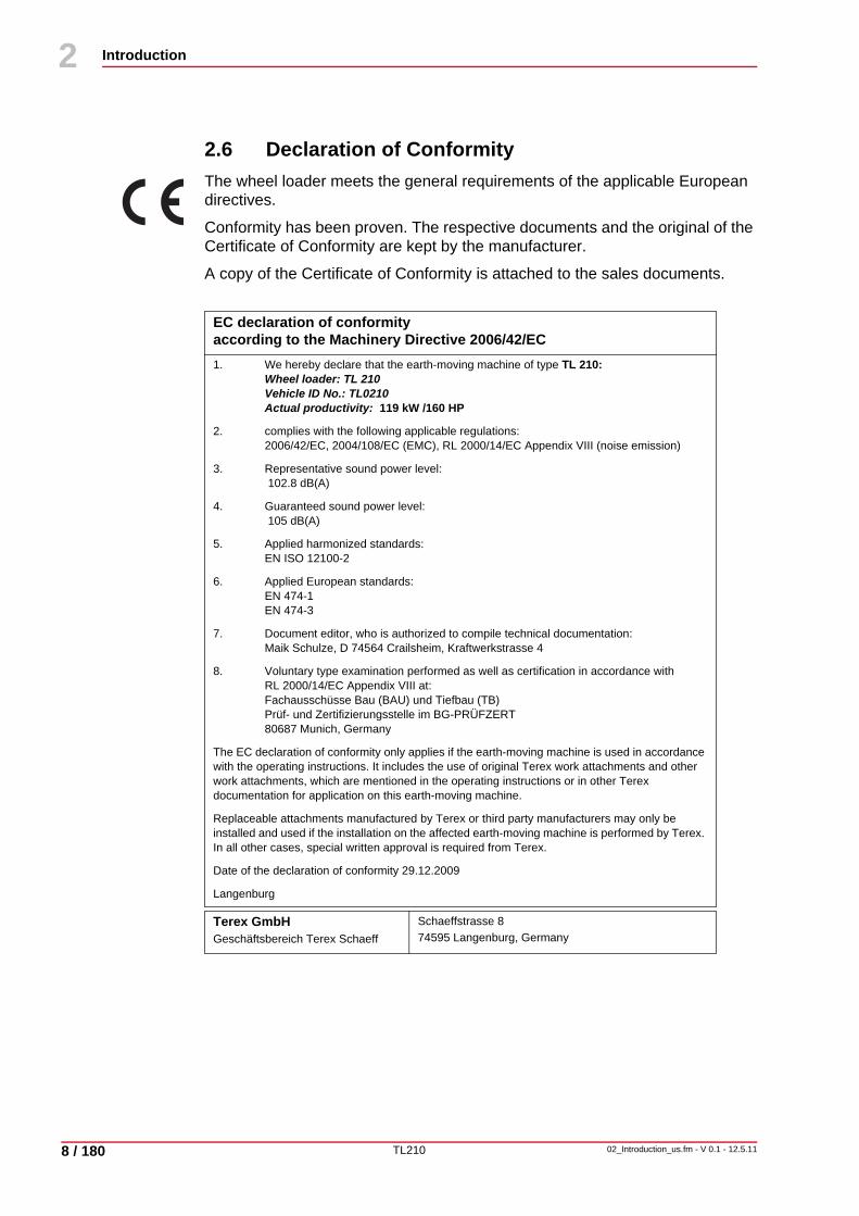
2.6 Declaration of ConformityThe wheel loader meets the general requirements of the applicable European directives.
Conformity has been proven. The respective documents and the original of the Certificate of Conformity are kept by the manufacturer.
A copy of the Certificate of Conformity is attached to the sales documents.
EC declaration of conformityaccording to the Machinery Directive 2006/42/EC1. We hereby declare that the earth-moving machine of type TL 210:
Wheel loader: TL 210Vehicle ID No.: TL0210Actual productivity: 119 kW /160 HP
2. complies with the following applicable regulations:2006/42/EC, 2004/108/EC (EMC), RL 2000/14/EC Appendix VIII (noise emission)
3. Representative sound power level: 102.8 dB(A)
4. Guaranteed sound power level: 105 dB(A)
5. Applied harmonized standards:EN ISO 12100-2
6. Applied European standards:EN 474-1EN 474-3
7. Document editor, who is authorized to compile technical documentation:Maik Schulze, D 74564 Crailsheim, Kraftwerkstrasse 4
8. Voluntary type examination performed as well as certification in accordance with RL 2000/14/EC Appendix VIII at: Fachausschüsse Bau (BAU) und Tiefbau (TB)Prüf- und Zertifizierungsstelle im BG-PRÜFZERT80687 Munich, Germany
The EC declaration of conformity only applies if the earth-moving machine is used in accordance with the operating instructions. It includes the use of original Terex work attachments and other work attachments, which are mentioned in the operating instructions or in other Terex documentation for application on this earth-moving machine.
Replaceable attachments manufactured by Terex or third party manufacturers may only be installed and used if the installation on the affected earth-moving machine is performed by Terex. In all other cases, special written approval is required from Terex.
Date of the declaration of conformity 29.12.2009
Langenburg
Terex GmbHGeschäftsbereich Terex Schaeff
Schaeffstrasse 874595 Langenburg, Germany

TL210
Introduction
02_Introduction_us.fm - V 0.1 - 12.5.11 9 / 180
2
10
Read the operating instructions thoroughly and follow the notes on safe operation before putting the earth-moving machine into operation.
National safety regulations - e.g. the Accident Prevention Regulations, “Earth-Moving Machinery” (BGR 500) and “Vehicles” (BGV D29) in the Federal Republic of Germany - must also be complied with when operating the earth-moving machine.
In addition to the Operating Instructions, legal regulations governing road traffic and road safety measures must also be observed. Such duties could also apply in respect of e.g. handling hazardous goods or the wearing of personal safety gear.
Furthermore, safety laws governing work in particular locations (tunnels, adits, quarries, pontoons, contaminated areas, etc.) must likewise be observed.

TL210
Introduction
10 / 180
2
02_Introduction_us.fm - V 0.1 - 12.5.11
10
2.7 Product Identifikation Number (PIN) plateVehicle type and product identification number are stamped on the PIN plate.
Fig. 2-1
1 Vehicle type2 Product identification numbers
NotePlease state the vehicle type and product identification number when making inquiries or placing orders, and in all written correspondence.

TL210
Safety
03_Safety_us.fm - V 0.1 - 12.5.11 11 / 180
3
30
3 Safety
3.1 General safety notes
3.1.1 Safety symbolThe safety alert symbol is used to alert you to potential personal injury hazards.
Obey all safety messages that follow this symbol to avoid possible injury or death.
3.1.2 Hazard ClassificationDANGER indicates an imminently hazardous situation which, if the safety regulations are not observed, will result in death or serious injury.
WARNING indicates a potentially hazardous situation which, if the safety regulations are not observed, may result in death or serious injury.
CAUTION indicates a potentially hazardous situation which, if the safety regulations are not observed, may result in property or equipment damage, or minor or moderate personal injury.
NOTICE indicates a potentially hazardous situation which, if the safety regulations are not observed, may result in property or equipment damage.
Notes
DANGER
WARNING
CAUTION
NOTICE
NoteThis symbol is employed for information containing important notes about the correct use and/or how to proceed. Non-compliance may lead to malfunction.

TL210
Safety
12 / 180
3
03_Safety_us.fm - V 0.1 - 12.5.11
30
3.1.3 Descriptions of hazard pictorialsThe symbols used in this Manual and/or on the Wheeled Excavator identify the following hazards:
Warning of explosion / burn hazard
If the required precautionary measures are not taken, death, burns or blindness due to ignition of explosive gases or contact with corrosive acid may occur.
Warning of injection hazard
If the required precautionary measures are not taken, escaping fluid under pressure can penetrate skin, causing serious injury.
Warning of burn hazard
If the required precautionary measures are not taken, contact with hot surfaces can cause burns.
Warning of entanglement hazard
If the required precautionary measures are not taken, death or serious injury can result from contact with rotating drivelines.
Warning of entanglement hazard
If the required precautionary measures are not taken, rotating parts can cause personal injury.
Warning of crush hazard
If the required precautionary measures are not taken, severe injury and death from crushing can occur in articulating area when machine turns.
Warning of crush hazard
If the required precautionary measures are not taken, death or serious injury can result from contact with moving loader arm or bucket.
Warning of crush hazard
If the required precautionary measures are not taken, death or injury can result from sudden or accidential movement of loader arm.

TL210
Safety
03_Safety_us.fm - V 0.1 - 12.5.11 13 / 180
3
30
3.2 Location of safety signsThe safety signs are located in the following machine positions:
Fig. 3-1 Locations of safety signs
1 Crush hazard2 Crush hazard3 Burn hazard4 Entanglement hazard5 Explosion / Burn hazard6 Crush hazard7 Entanglement hazard8 Injection hazard9 Crush hazard
32
34
93115
29
Guard
12
30
Frame - engine hoodFrame - engine hood
1
2
45
689 7
35
3
210
TL210
Safety
14 / 180
3
03_Safety_us.fm - V 0.1 - 12.5.11
30
Servicing and replacing safety signsThe safety of the operator always has to come first.
Safety signs must always be kept in good condition and legible.Replace any safety sign which has been damaged or disappeared.Use mild detergents and water to clean the safety signs. Do not use any solvent containing cleansers.Always specify machine serial number and language when ordering safety signs.
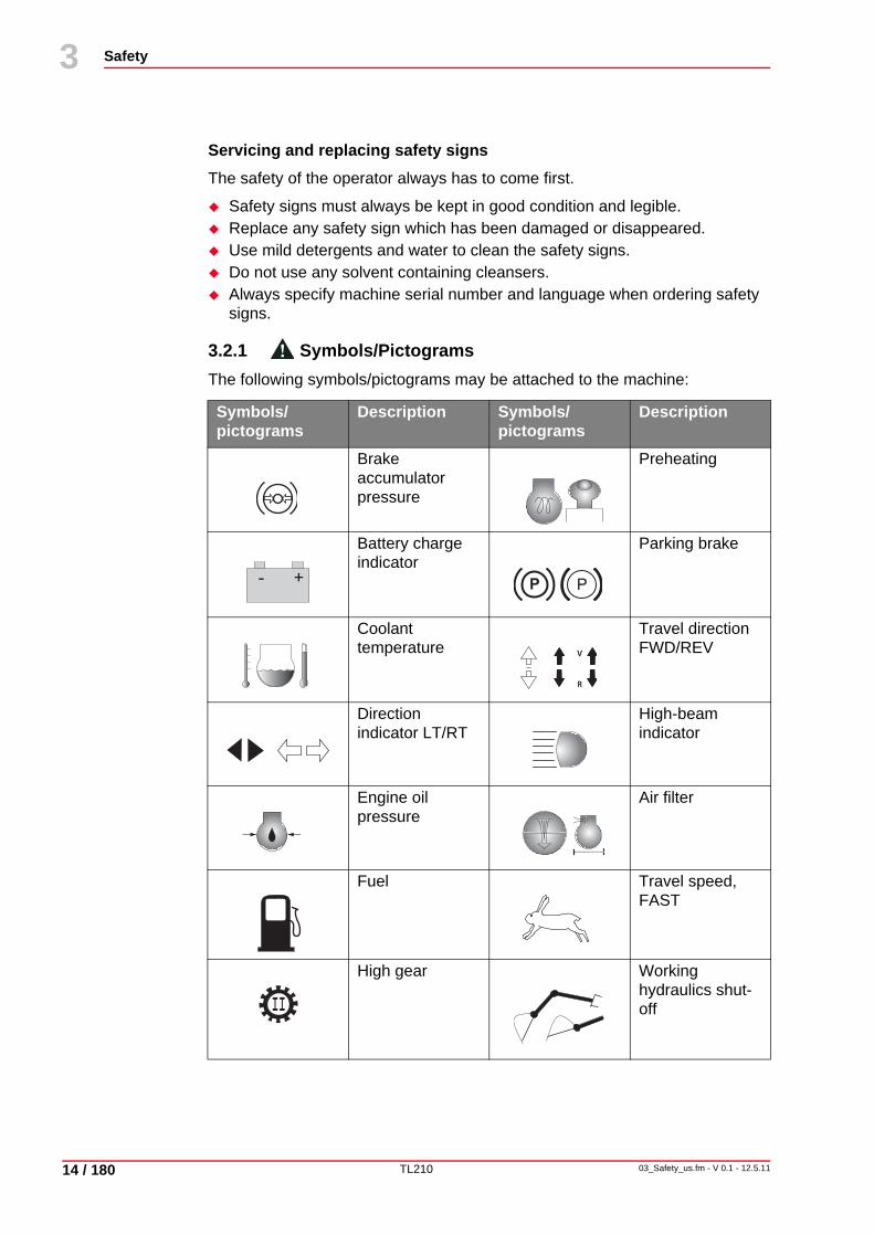
3.2.1 Symbols/PictogramsThe following symbols/pictograms may be attached to the machine:
Symbols/pictograms
Description Symbols/pictograms
Description
Brake accumulator pressure
Preheating
Battery charge indicator
Parking brake
Coolant temperature
Travel direction FWD/REV
Direction indicator LT/RT
High-beam indicator
Engine oil pressure
Air filter
Fuel Travel speed, FAST
High gear Working hydraulics shut-off
- + P P
V
R
V
R
II

TL210
Safety
03_Safety_us.fm - V 0.1 - 12.5.11 15 / 180
3
30
Bucket return positioner
Changeover fan/engine cooling
Windshield wiper Windshield washing function
Working floodlights
Hazard warning system
Ride control system
Float position
Unlocked Emergency steering
Fan levels Cooling
Circulating air Temperature
Carbon filter contamination
Coolant level
Hydraulic oil Hydraulic oil level
Horn Grease gun
Symbols/pictograms
Description Symbols/pictograms
Description
TL210
Safety
16 / 180
3
03_Safety_us.fm - V 0.1 - 12.5.11
30
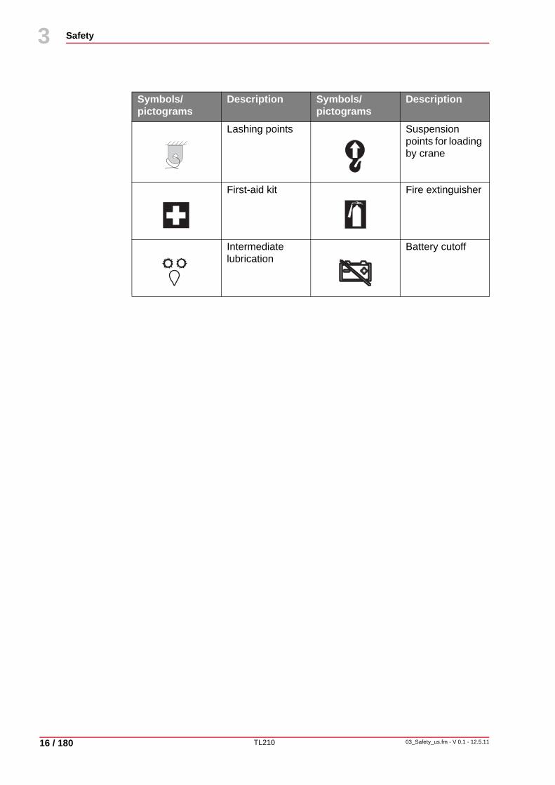
Lashing points Suspension points for loading by crane
First-aid kit Fire extinguisher
Intermediate lubrication
Battery cutoff
Symbols/pictograms
Description Symbols/pictograms
Description
TL210
Safety
03_Safety_us.fm - V 0.1 - 12.5.11 17 / 180
3
30
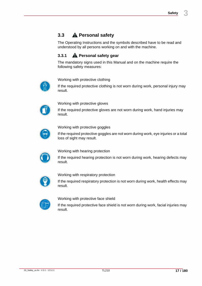
3.3 Personal safetyThe Operating Instructions and the symbols described have to be read and understood by all persons working on and with the machine.
3.3.1 Personal safety gearThe mandatory signs used in this Manual and on the machine require the following safety measures:
Working with protective clothing
If the required protective clothing is not worn during work, personal injury may result.
Working with protective gloves
If the required protective gloves are not worn during work, hand injuries may result.
Working with protective goggles
If the required protective goggles are not worn during work, eye injuries or a total loss of sight may result.
Working with hearing protection
If the required hearing protection is not worn during work, hearing defects may result.
Working with respiratory protection
If the required respiratory protection is not worn during work, health effects may result.
Working with protective face shield
If the required protective face shield is not worn during work, facial injuries may result.

TL210
Safety
18 / 180
3
03_Safety_us.fm - V 0.1 - 12.5.11
30
3.4 Work zone safety
3.4.1 General work zone regulations and safe work practicesRead the operating instructions thoroughly and follow the notes regarding safe operation before starting up the wheel loader.
In addition to the operating instructions observe also the national legal and miscellaneous regulations applicable at the deployment location of the machine:
• Industrial safety• Accident prevention• Health protection • Environmental protection• Public traffic
Such duties could also apply in respect of e. g. handling hazardous goods or the wearing of personal safety gear.
Furthermore, safety laws governing work in particular locations (tunnels, adits, quarries, pontoons, contaminated areas, etc.) must likewise be observed, e. g.:
• Working in the vicinity of tracks (BGV D33)• Construction work (BGV C22)• Safety rules for construction work underground (BGR 160)• Tunnel excavating machines (DIN EN 12111)
The plant operator and the machine driver are responsible for ensuring that the safety regulations are upheld. The customer must in any case become familiar with the locally valid rules and regulations.
3.4.2 Deactivation and protection against re-activationEnsure all the following safety instructions are read prior to using or servicing the machine, to avoid personal injury.
Before breaks and the end of work park the machine on a solid and level base. The machine is only to be parked in places where it does not obstruct e. g. the public or the construction site traffic. Place the working attachment on the floor.Shut down the engine and pull out the ignition key.Turn battery switch to „off“ and remove key.Close or lock windows and doors.

TL210
Safety
03_Safety_us.fm - V 0.1 - 12.5.11 19 / 180
3
30
3.5 General safety notes• It is important to refrain from any working methods which impair safety.• The machine may only be operated with cabin or canopy.• The machine is only to be used if it is in a safe, operational condition.• The manufacturer’s instructions must be complied with for operation,
maintenance, repair, assembly, and transportation.• The plant operator must provide additional special safety instructions,
wherever necessary, for specific local conditions.• The operating instructions and any information pertaining to safety must be
carefully kept in the driver's cab.• The operating instructions and safety notes must be complete and fully
readable.
Before starting work:
Before starting work become acquainted with the First Aid and Rescue Possibilities (Emergency Doctor, Fire Brigade, Rescue Services).Check that the first aid kit is available and properly stocked.Become familiar with the location and the operation of fire extinguishers on the machine, as well as the local fire alarm and fire fighting facilities.Fasten any loose parts, e. g. tools and other accessories.Close all doors, windows, hoods, flaps, or secure these in open condition against unintended closing.
During work Do not make any safety features ineffective and do not remove any safety features.Wear protective clothing for operation. Take off rings, scarves, open jackets. Protective goggles, protective boots, helmets, gloves, reflecting jackets, ear-muffs, etc. may be required for certain work.
Regulations concerning environmental protection
Comply with the valid environmental regulations when working on or with the machine.Take special care that no environmentally harmful substances, like lubrication grease and oils, hydraulic oils, fuels, coolants and solvent containing cleaning fluids do not seep into the ground or the sewer when performing installation, repair and maintenance work. These substances must be collected, transported, kept and disposed of in suitable containers.If the substances listed above enter into the soil, the leak or outlet must be stopped immediately and the fluid must be cleaned up with a suitable absorbent material. If necessary, the soil involved must be removed. Properly dispose of binding agent and excavated material, comply with valid environmental regulations.
TL210
Safety
20 / 180
3
03_Safety_us.fm - V 0.1 - 12.5.11
30
3.6 OperationOperate the control equipment only from the driver's seat.To access and exit the machine use only the steps and areas provided for this purpose.Make sure that the operator’s stand, access steps and other surfaces on the machine, which have to be stepped on, are kept free of dirt, grease, oil, ice, and snow.
3.7 Hazard zoneNobody must be allowed to remain in the hazard zone of the machine.
The hazard zone encompasses the area around the machine in which persons may be injured by movements of the machine during operation, its work implements and attachments, or by swinging out or falling loads.
The machine operator is only to work the machine if nobody is in the hazard zone.The machine operator must give a warning signal to persons who may be in danger.Stop work with the machine, if persons remain in the hazard zone despite the warning.To ensure no danger of crushing, a sufficient safety distance (min. 0.5 m/0.55 yd) must be kept from solid objects, e. g. buildings, excavation slopes, scaffolding, other crawler excavators, etc.If the safety distance cannot be kept, fence off the area between solid construction elements and the working range of the machine.If conditions are such that the machine operator’s view of the driving and working zone is restricted, he must be guided or the driving and working zone must be secured by means of a solid barricade.
3.8 Transporting personsThe machine must not be used to transport persons.

TL210
Safety
03_Safety_us.fm - V 0.1 - 12.5.11 21 / 180
3
30
3.9 StabilityThe machine must be used, driven and operated in such a manner that its stability against overturning is ensured at all times.Match the travel speed to the local conditions.Do not exceed the permissible load for the machine.Keep the machine away from the edges of quarries, pits, mounds and slopes, to ensure there is no risk of falling. If this is not possible, the machine must be secured to prevent rolling or slipping.
3.9.1 Stability on sloping groundThere is danger of overturning on sloped base.
There is particular danger when working (digging and lifting) on soft bases.
An increased degree of caution is required on slopes over 10° (17.6%).
The tilt angle increases when driving over obstacles one-sided.
Always drive straight up or down inclines. Driving at an angle on an incline or cross-wise over an incline is extremely dangerous.Do not turn on the incline and do not drive cross-wise over it. Always return to a level spot to change the position of the machine and then drive back on the incline.
Test the standing stability of the machine before beginning work.Observe the stability specifications. The stability specifications are based on a level, solid and even base.All stability calculations must be made with a horizontally positioned machine on a uniform and solid ground. If the machine is used while working under conditions that do not meet this requirement (such as loose and irregular ground, no horizontal position, side loads, etc.) these conditions must be taken into consideration by the operator.Never exceed the maximum allowable inclination angle of the machine.Secure the machine against rolling or sliding.Begin work slowly.

TL210
Safety
22 / 180
3
03_Safety_us.fm - V 0.1 - 12.5.11
30
3.10 DrivingBefore putting the machine into operation, the driver's seat, mirrors and operator controls must be adjusted so as to ensure safe working.Always wear the seat belt.Keep windows clean and free of ice.
Driving tracks must be designed so as to ensure smooth, safe operation, i.e. they must be sufficiently wide, on ground which has as few slopes as possible and sufficient carrying capacity.
Downhill tracks must be set out in such a way that machines can be safely braked.
Before driving downhill, the appropriate gear for the terrain must be selected and the gear lever not be moved during downhill travel (road or off-road gear). On steep drops and uphill gradients, the load must be carried on the uphill side, if possible, in order to increase stability.The carrying capacity of bridges, cellar roofs, vaults, etc. must be verified before the earth-moving machine can drive over them.Check the clear dimensions of constructions before entering into subways, tunnels, etc.
It is the plant operator's responsibility to ensure that equipment such as first-aid box, warning triangle, hazard lights are kept with the machine according to the traffic regulations valid in the user’s country and that the driver has the appropriate license as required by the national traffic laws of the country in question.
Outside areas covered by general traffic regulations, e. g. on factory premises, traffic regulations should be applied in the proper manner. This should also apply with regard to drivers’ licenses.
3.11 Working OperationDaily before commencing work and after every change of work attachments, a check must be carried out to ensure that the work attachment is correctly fastened, and the quick-mount hitch is properly locked. Move the working attachment carefully in low height. During this check nobody must be allowed to remain in the danger zone of the earth-moving machine.You should only swing the work equipment over occupied drivers' seats, operator consoles and workplaces of other machines if these are protected by canopies (FOPS).If a cab does not have the required protection, the driver of this vehicle must leave the operator’s stand while the work equipment is being swung overhead.Load the machine in such a manner, that it is not overloaded and no material is lost while the machine is driving. Load the machine from the lowest possible height.At dumping points, the machine may only be operated if suitable measures have been taken to prevent rolling or falling.

TL210
Safety
03_Safety_us.fm - V 0.1 - 12.5.11 23 / 180
3
30
3.12 GuidesGuides must be easily recognizable, e. g. by means of reflective clothing. They must remain within the machine operator’s field of vision.
While guiding the machine, guides shall not be given other jobs which may distract them from their task.
3.13 Use under the danger of falling objectsIf there is danger of falling objects use the machine only if the driver's seat is protected by a canopy FOPS. A front guard must be employed if there is a risk of materials breaking through into the cab.In front of walls e. g. of stacked materials, the machine must be operated and positioned in such a way that the driver's seat and entry to the driver's seat are not situated on the side facing the wall.Only use the machine for demolition work if no persons are endangered and if the machine is equipped with protective roof (FOPS) and front protection mounted to the operator's stand. See regulations book "Demolition work" (BGI 665) published by the German Tiefbau-Berufsgenossenschaft (Civil Engineering Employer’s Liability Insurance Association).
3.14 Working in the vicinity of underground power lines
Before commencing excavating work using the machine, it must be determined whether any underground power lines are present in the intended working zone which may present a hazard to persons.If underground power lines are present, their exact position and course must be determined in consultation with the proprietor or operator of the lines, and the necessary safety precautions decided and implemented.Before starting any earth work clearly mark the route of lines in the construction site area under supervision. If the position of lines cannot be determined, search ditches must be dug - manually, if need be.In case of unexpected detection or damaging of underground power lines or their protective coverings stop work immediately and inform the supervisor.

TL210
Safety
24 / 180
3
03_Safety_us.fm - V 0.1 - 12.5.11
30
3.15 Working in the vicinity of overhead power linesIf the machine is being used in the vicinity of overhead power lines and trolley wires, a safety distance which varies depending on the nominal voltage of the overhead line must be maintained between the lines and the machine and its work equipment, to prevent current overspill. This also applies to the distance between these lines and attached implements or loads.
Specified safety distance
The safety distance depends on the rated voltage of the overhead power line.
Tab. 3-1 Prescribed safety distances
Also consider all working movements of the machine, e. g. positions of the work equipment and the dimensions of attached loads. Consider also uneven ground which could cause a slanted position of the machine and thus bring it closer to the overhead power line.During work in windy conditions, both overhead lines and work equipment may swing out, thus reducing the safety distance.
If it is impossible to maintain sufficient distance from overhead power lines and trolley wires, the plant operator must consult with the proprietor or operator of the overhead lines to find other safety precautions to prevent current overspill. Such measures could be, e. g.
• Switching off the current• Re-routing the overhead line• Wiring• Limitation of the working range of the machine.
Nominal voltage Safety distance> 1,000 V 1.0 m/32.8 ft
more than 1 kV > 110 kV 3.0 m/9.8 ft
more than 110 kV > 220 kV 4.0 m/13.1 ft
more than 220 kV > 1,380 kV 5.0 m/16.4 ft
nominal voltage unknown 5.0 m/16.4 ft

TL210
Safety
03_Safety_us.fm - V 0.1 - 12.5.11 25 / 180
3
30
3.16 Operation in closed spacesIf machines are to be used in closed spaces, these areas must be sufficiently ventilated and special regulations observed.
3.17 Work stoppagesBefore rest periods and the end of work park the machine on a level base of sufficient load bearing capacity and secure it reliably against unintended moving.Before rest periods and the end of work lower the working attachment to the grod to prevent it from moving.Do not leave the machine before you have lowered and secured the work equipment.
Machines are only to be parked in places where they do not obstruct, e. g. public or construction site traffic. Warning devices, e. g. triangles, warning cordons, flashing or hazard lights are to be used if necessary.
Before leaving the operator's stand return all control elements to neutral position, apply the brakes and switch off the working hydraulics.Before exiting the machine shut down the engine and secure it against unauthorized restarting (e. g. by pulling out the ignition key and disconnecting the battery if necessary).

TL210
Safety
26 / 180
3
03_Safety_us.fm - V 0.1 - 12.5.11
30
3.18 Load hook applicationsLoad hook applications are the hoisting, transporting and lowering of loads with the aid of a fixing device (rope, chain, etc.), whereby the assistance of personnel is required to attach and release the load. Such work covers e. g. the lifting and lowering of pipes, tubbing rings or containers using earth-moving machines.
Earth-moving machines are only to be used for load hook applications if the prescribed safety devices are present and in full working order. For earth-moving machines, these are:
• Secure attachment of loading implements• Carrying capacity
Loads must be attached in such a way that they cannot slip or fall out.Personnel guiding the machine and attaching loads must always remain in the machine operator’s field of vision.Keep loads as close above the ground as possible and avoid swinging about.Move the machine with the suspended load only if the travel ground is level or almost level.If the machine is used for load hook applications, personnel attaching loads is only to approach the lifting frame from the side and with the machine operator’s permission. The machine operator is only to give his permission if the machine is standing still and the work equipment is not in motion.Do not use fixing devices (ropes, chains, shackles) which are damaged or of inadequate dimensions. Always wear protective gloves when working with lifting tackle

TL210
Safety
03_Safety_us.fm - V 0.1 - 12.5.11 27 / 180
3
30
3.19 Conversions, maintenance and repairsThe machine must only be converted, maintained or repaired under the guidance of a suitable person designated by the plant operator and following the manufacturer’s Operating Instructions.
After changing the work attachments convince yourself of the correct fastening of the work attachments.
Work on e. g.
• brake systems,• steering systems,• hydraulic systems,• electric systems
of the machine is only to be carried out by expert personnel specially trained in these areas.
Stability must be ensured during all type of work on the machine at all times.
Always secure the machine with wheel chocks against rolling when working on or especially under the machine. Secure the work equipment against movement by lowering it to the ground or by applying equivalent measures, e. g. cylinder supports, trestles. As long as the engine is running, the unprotected working range must not be entered.Attach the lifting gear for jacking up the machine so that it cannot slip off. Make sure that the jacks are placed exactly vertically.The raised machine must be supported with suitable structures, e. g. crosswise stacked planks, square timbers or steel trusses.Stabilize the machine that has been lifted with the work equipment, immediately after lifting with a supporting structure. Work under raised machines which are only supported by their hydraulics is forbidden.Shut down the engine before any maintenance and repair work. These requirements may only be ignored in the case of maintenance or repair work which cannot be performed without the engine/motor(s) running.Always depressurize the hydraulic system before starting corresponding maintenance and repair work. With the engine turned off, lower the work equipment to the ground and actuate all hydraulic control levers until there is no more pressure in the hydraulic system.Before starting work in the electric system or for welding work on the machine disconnect the battery connection.When disconnecting the battery disconnect the minus pole first and the plus pole after. Reconnect in reverse order.
TL210
Safety
28 / 180
3
03_Safety_us.fm - V 0.1 - 12.5.11
30
When performing repair work in the area of the battery cover the battery with insulating material. Do not lay any tools on the battery.Open or remove the safety features from moving parts of the machine only after the machine has been shut down and the drive is properly secured against unauthorized restarting. Protective devices are e. g. engine/motor covers, doors, protective grating, trim.Upon completion of assembly, maintenance or repair work, all protective devices must once more be attached in the proper manner.Welding work on load-bearing parts of the machine are only permitted after consultation with the manufacturer and in accordance with recognized welding principles.Do not perform welding or drilling work on safety structures (ROPS, FOPS).Alterations, e. g. welding of the hydraulic system, are only to be undertaken with the manufacturer’s permission.Before commencing work on the hydraulic system, the operating pressure, pilot pressure, back pressure and pressure inside the tank must be relieved.Observe the safety data sheets issued by the mineral oil companies.Swallowing lubricants as well as long and repeated skin contact can be hazardous to health and should therefore be avoided. When used properly, there is no particular danger to health. Use only hydraulic hoses specified by the manufacturer.Route and assemble hydraulic hoses correctly.In the vicinity of fuel or batteries, smoking and naked flames are prohibited.
Safe working conditions and good working order of the machine are prerequisites for efficient work. Your Terex wheel loader fulfils these requirements when correctly handled and when serviced and maintained as specified.
Avoid malfunctions by cautiously watching the machine’s functions and by using the specified fuels and lubricants.Trained specialist personnel are responsible for any servicing of the machine which requires expert knowledge. Inspections and repairs must therefore be carried out by your dealer’s customer service.Within the warranty period damage claims can only be lodged if the specified intervals for maintenance and inspection work have been complied with.After the warranty period, too, regular maintenance must be performed in order to ensure that the machine is constantly in good working order and enjoys a reasonable service life.Insist that only original Terex spare parts are used in the event of any repair work. In this way, you will have a product of lasting high quality, thereby ensuring that your machine maintains its original condition.

TL210
Safety
03_Safety_us.fm - V 0.1 - 12.5.11 29 / 180
3
30
3.20 Recovery, loading and transportingMachines shall only be loaded onto recovery vehicles when adequate towing vehicles are used.
Use the lifting points specified by the manufacturer.For loading and transportation secure the machine and the required auxiliary devices against unintended movements.Clean running gear and chassis of the machine from slurry, snow and ice, so that the loading ramp can be approached without the risk of slipping.For transport by truck, low loader or railway secure the machine reliably with wheel chocks and by fastening it at the lashing points.Before setting off, the route to be taken must be examined to determine whether the roads are wide enough, entrances and passages under bridges are large enough and that roads and bridges have sufficient carrying capacity.
3.21 Monitoring and inspectionsHave the machine inspected by an expert (e. g. machine engineer or machine foreman) according to the regulations in force in the user's country (e.g. Accident Prevention Regulations in Germany):• Before the machine is put into operation for the first time and after
significant modifications have been made• At least once a year• In the meantime, according to operating conditions and local
environmentsKeep record of the inspection report and file it until the next inspection.Before the beginning of the shift check the machine following the inspection plan.Replace hydraulic hoses as soon as the following damage is noticed:• Damage to the outer layer which reaches the intermediate layer.• Embrittled patches on the outer layer.• Deformations when under pressure or without pressure which differ from
the original shape of the installed hose.• Leaks.• Damage to hose fittings or to the connection between the fitting and the
hose.Check the coolant level only with the engine shut down, carefully turn the cover to relieve overpressure.Check the function of the safety devices before using the machine.In case of any faults inform the supervisor immediately, at change of shifts inform also the new operator.In case of faults that could endanger the operating safety of the machine stop operation until the fault is corrected.

TL210
Safety
30 / 180
3
03_Safety_us.fm - V 0.1 - 12.5.11
30
3.22 Fire preventionShut down the engine before refueling and take care when the engine is hot.Never smoke or handle open flames whilst refueling the tank of the machine.Keep the fire extinguisher near the operator's stand. Its location must be identified by the fire extinguisher symbol.
3.23 Emergency exitThe right-hand cab door acts as an emergency exit.
3.24 Notes concerning residual dangers
3.24.1 Failure of hydraulic systemIf the hydraulic system fails because the engine is not running, the hydraulic pump is damaged or hydraulic oil has been lost, only the following emergency functions can still be performed:
• Manual steering • Emergency support through auxiliary pump (1-2 min.) and• Lowering work equipment (only if ignition is switched on).

TL210
Initial installation and adjustments
04_Initial_installation_us.fm - V 0.1 - 12.5.11 31 / 180
4
32
4 Initial installation and adjustments
4.1 Initial familiarization
The machine must only be operated by properly trained and instructed personnel. For this purpose a corresponding instruction session and training is conducted when the machine is handed over.
4.1.1 Handing over the machine and instructing the operatorThe following checklist should be followed when handing over the machine to the operator:
Operating instructions
Go through the Operating Instructions (page by page) and explain them in detail through practical training on the machine. Items which are particularly important include:• Safety section• Accident Prevention Regulations published by the employer’s liability
insurance associations in the users country• Technical data• Operator controls, indicating and warning elements• Checks before putting the machine into operation• Engine running-in instructions• Starting and shutting down the engine• Driving• Recovery and transport of the machine• Operation of all functions• Explanation of maintenance intervals and points according to
Maintenance and Inspection Plan by demonstrating and explaining maintenance points on machine
• Lubrication intervals and points of lubrication according to lubrication chart and demonstration of these points on the machine
Spare parts list Explain the structure of spare parts list, figures and the associated texts. Explain that spare parts orders must always be accompanied by machine type, vehicle identification number ("Fz-Id.Nr."), parts designation, complete spare part number, quantity, delivery address, etc.
Warranty Explain the warranty conditions.Explain the inspection cards with a hint to the maintenance and inspection plan.Fill in the warranty/handing over card correctly and send it back to us.
NoteInitial inspection must be carried out before commissioning. See chapter 6.6 "Maintenance and Inspection Plan", page 59.

TL210
Initial installation and adjustments
32 / 180
4
04_Initial_installation_us.fm - V 0.1 - 12.5.11
32

TL210
Description of the Wheel Loader
05_Description_us.fm - V 0.1 - 12.5.11 33 / 180
5
44
5 Description of the Wheel Loader
5.1 Overview of wheel loader
Fig. 5-1 Overview of wheel loader
1 Bucket2 Quick-attach system3 Lifting frame4 Front-end5 Cab6 Door catch7 Engine8 Articulation9 Type laBattery10 Fuel tank11 Hydraulic oil tank12 Radiator and hydraulic oil cooler
2
5
74
8
9
1012
11
3
6
1
13
4560_5001
TL210
Description of the Wheel Loader
34 / 180
5
05_Description_us.fm - V 0.1 - 12.5.11
44
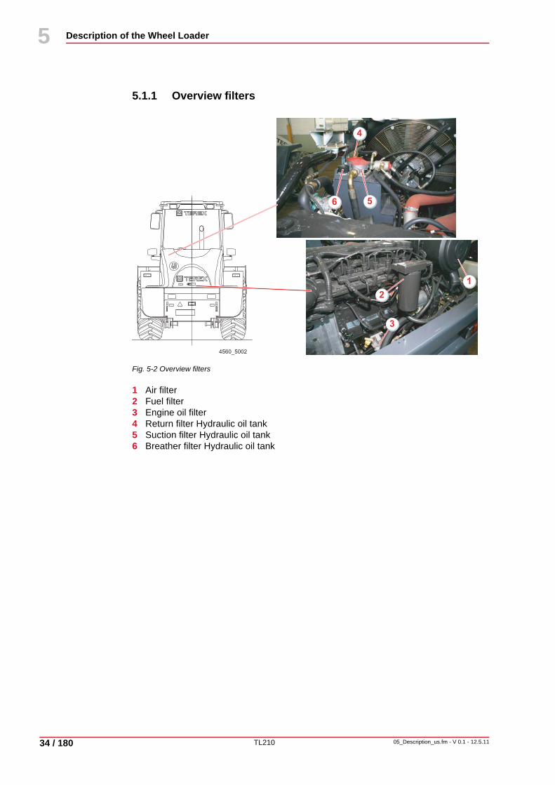
5.1.1 Overview filters
Fig. 5-2 Overview filters
1 Air filter2 Fuel filter3 Engine oil filter4 Return filter Hydraulic oil tank5 Suction filter Hydraulic oil tank 6 Breather filter Hydraulic oil tank
3
2
1
4
6 5
4560_5002

TL210
Description of the Wheel Loader
05_Description_us.fm - V 0.1 - 12.5.11 35 / 180
5
44
5.2 Display elements and operating controls in operator's stand
5.2.1 Operating controls
Fig. 5-3 Operating controls
1 Brake-inching pedal2 Lighting, direction indicator, horn and low-high beam (steering-column switch)3 Steering wheel 4 Tilt and height adjustment of steering wheel5 Accelerator pedal6 Control lever - loading equipment7 Operation - additional control circuit OFF8 Operation - additional control circuit ON9 Preselection of travel direction (function only active if working hydraulics are
activated)10 --
NoteThe following lists include non-standard equipment!
UNIDECKUNIDECK
P
- +
HAZARD
P
AUTO OFF
0I
4560_5003
3
7 8
10
2
5
4
9
1
6

TL210
Description of the Wheel Loader
36 / 180
5
05_Description_us.fm - V 0.1 - 12.5.11
44
5.2.2 Front control console
Fig. 5-4 Front control console
1 Brake accumulator pressure2 Pre-heating monitor3 Charge control lamp4 Parking brake5 Travel direction, forward6 Display with operating hour meter7 Travel direction, reverse8 Direction indicator9 High beam10 Engine oil pressure11 Air filter indicator12 Fuel-level indicator13 Coolant temperature14 Travel speed switch - FAST/SLOW15 --16 Multi-function switch (lock for working hydraulics cut-off and activation of the
direction-of-travel preselection switches (9) page 35 and (17) page 36)17 Preselection of travel direction (function only active if working hydraulics are
disabled)18 Bucket return positioner (option)19 Engine cooler reversing fan changeover switch – automatic / temperature-controlled
/ manual20 Windshield washing function - front/ rear21 Windshield wiper, front22 Windshield wiper, rear
UNIDECKUNIDECK
P
-- +
765
9
10
14 16 18 20 2217 19 21
11
8
1213
2
3
4
1
4560_500415

TL210
Description of the Wheel Loader
05_Description_us.fm - V 0.1 - 12.5.11 37 / 180
5
44
5.2.3 Lateral control console
Fig. 5-5 Lateral control console
1 Reverse signal off2 Working floodlight, front3 Working floodlight, rear4 Hazard warning switch5 Flow rate adjustment for additional control circuit6 Ride control system (option)7 Preselection switch float position - OFF/Continuous operation8 Preselection switch of additional control circuit - OFF/Impulse/Continuous operation9 Parking brake preselection switch ON/OFF, ON = locked10 Motor control lights11 Emergency steering Automatic/ON12 Intermediate lubrication (manual operation of central lubrication)13 Control unit heating / Klimatronic14 Glow plug and starter switch
HAZARD
P
AUTO OFF
0I
4560_5005
R
Zwischen- schmierung
Intermediatelubrication
HAZARD
P
R
Zwischen- schmierung
Intermediatelubrication
1 2 3 4
14
13
6 7 8 9
10 11 12
5

TL210
Description of the Wheel Loader
38 / 180
5
05_Description_us.fm - V 0.1 - 12.5.11
44
5.2.4 Control unit heating / Klimatronic
Fig. 5-6 Control unit heating / Klimatronic
1 Lowering temperature by 1° C/33.8° F2 Raising temperature by 1° C/33.8° F3 Temperature, error code display4 Fan level display (LED)5 Increasing fan speed by 1 level6 Lowering fan speed by 1 level7 Button for temperature display8 Interior space temperature sensor9 Circulating air button and display10 Cooling button and display11 Automatic diagnosis button and display
AUTO OFF
11 10 9 8
3 4
52
1 6
7
4560_5006

TL210
Description of the Wheel Loader
05_Description_us.fm - V 0.1 - 12.5.11 39 / 180
5
44
5.2.5 Display
Fig. 5-7 Display
1 Speed indicator2 Monitor indicator "manual transmission range I"3 Operating hour meter4 Monitor - indicator "manual transmission, range II" (optional for high-speed version)5 Soot filter clogging indicator (option)6 Hydraulic oil filter clogging indicator7 Hydraulic oil level8 Coolant level
12 km/h
00014,0 h
I
21 km/h
00014,0 h
I
12 km/hI
II
1
5 6 7 8
2
3
4
4560_5007
TL210
Description of the Wheel Loader
40 / 180
5
05_Description_us.fm - V 0.1 - 12.5.11
44
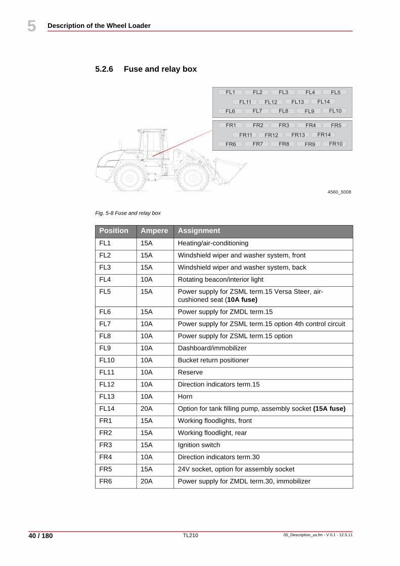
5.2.6 Fuse and relay box
Fig. 5-8 Fuse and relay box
Position Ampere AssignmentFL1 15A Heating/air-conditioning
FL2 15A Windshield wiper and washer system, front
FL3 15A Windshield wiper and washer system, back
FL4 10A Rotating beacon/interior light
FL5 15A Power supply for ZSML term.15 Versa Steer, air-cushioned seat (10A fuse)
FL6 15A Power supply for ZMDL term.15
FL7 10A Power supply for ZSML term.15 option 4th control circuit
FL8 10A Power supply for ZSML term.15 option
FL9 10A Dashboard/immobilizer
FL10 10A Bucket return positioner
FL11 10A Reserve
FL12 10A Direction indicators term.15
FL13 10A Horn
FL14 20A Option for tank filling pump, assembly socket (15A fuse)
FR1 15A Working floodlights, front
FR2 15A Working floodlight, rear
FR3 15A Ignition switch
FR4 10A Direction indicators term.30
FR5 15A 24V socket, option for assembly socket
FR6 20A Power supply for ZMDL term.30, immobilizer
4560_5008
FL1 FL2 FL3 FL4 FL5
FL6 FL7 FL8 FL9 FL10
FL11 FL12 FL13 FL14
FR1 FR2 FR3 FR4 FR5
FR6 FR7 FR8 FR9 FR10
FR11 FR12 FR13 FR14
TL210
Description of the Wheel Loader
05_Description_us.fm - V 0.1 - 12.5.11 41 / 180
5
44
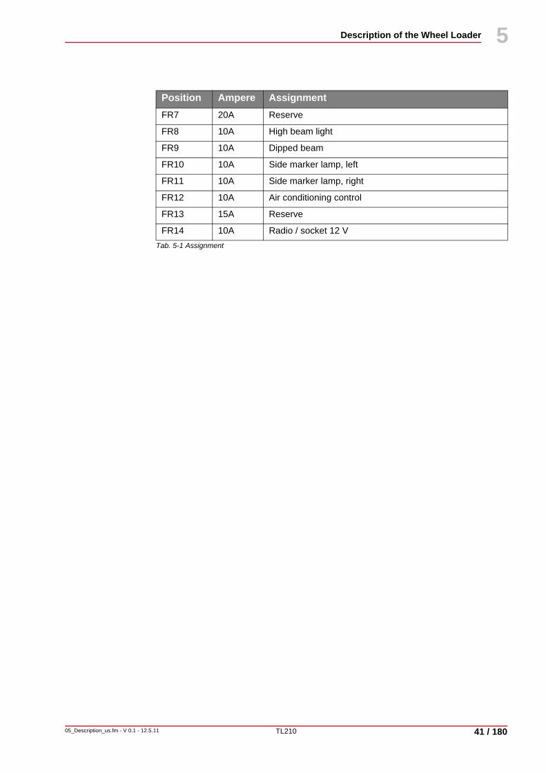
Tab. 5-1 Assignment
FR7 20A Reserve
FR8 10A High beam light
FR9 10A Dipped beam
FR10 10A Side marker lamp, left
FR11 10A Side marker lamp, right
FR12 10A Air conditioning control
FR13 15A Reserve
FR14 10A Radio / socket 12 V
Position Ampere Assignment

TL210
Description of the Wheel Loader
42 / 180
5
05_Description_us.fm - V 0.1 - 12.5.11
44
Fig. 5-9 Main input fuses
Tab. 5-2 Assignment Main input fuses
Position Ampere AssignmentF01 200A Emergency steering pump
F02 125A Fuse F005-F008
F03 125A Preheating system
F04 30A Power supply for control module ZSML
F05 30A Accelerator pedal, diagnosis socket, emergency steering pump
F06 30A Reserve
F07 50A Power supply for main fuse
F08 30A Power supply for engine ECU
F09 5A Accelerator pedal
K1 Starting relay
K2 Preheater relay
K3 Indicator relay
K4 Emergency steering pump
K6 Terminal 15
KK1 Compressor relay
KK2 Blower relay
KK3 Blower relay
KK4 Blower relay
KK5 Circulating air flap relay
KK6 Circulating air flap relay
4560_5009
TL210
Description of the Wheel Loader
05_Description_us.fm - V 0.1 - 12.5.11 43 / 180
5
44
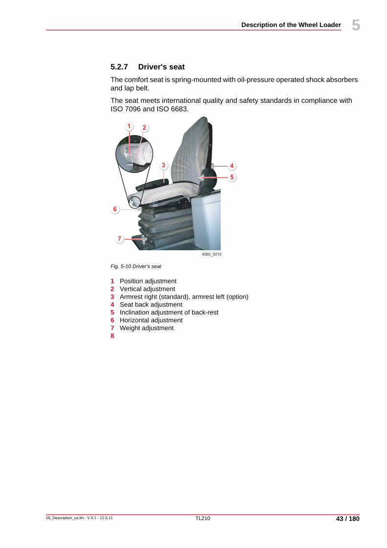
5.2.7 Driver's seatThe comfort seat is spring-mounted with oil-pressure operated shock absorbers and lap belt.
The seat meets international quality and safety standards in compliance with ISO 7096 and ISO 6683.
Fig. 5-10 Driver's seat
1 Position adjustment2 Vertical adjustment3 Armrest right (standard), armrest left (option)4 Seat back adjustment5 Inclination adjustment of back-rest6 Horizontal adjustment 7 Weight adjustment8
4
7
6
5
1
3
2
4560_5010

TL210
Description of the Wheel Loader
44 / 180
5
05_Description_us.fm - V 0.1 - 12.5.11
44
TL210
Maintenance
06_Maintenance_us.fm - V 0.1 - 12.5.11 45 / 180
6
10
6 Maintenance
6.1 GeneralThe good operating condition and life expectancy of machines are largely influenced by care and maintenance.
For this reason, it is in every machine owner’s interest to perform the specified maintenance work and comply with the service intervals. This chapter deals in detail with periodic maintenance, inspection and lubricating tasks.
The type-specific maintenance and inspection plan lists all work to be performed on the machine at regular intervals. Maintenance and inspection plans for this purpose are contained in every Instruction Book.
6.2 Care and cleaning
Cleaning the machineClean the machine in the parking position on a suitable base with oil separator.If working with a high pressure cleaner, a protective face shield and protective clothing must be worn.Neither a steam-jet nor a high-pressure cleaner must be used for cleaning during the first two months after the machine has been used for the first time, or when newly painted, to ensure that the paint can cure sufficiently.Do not use aggressive detergents to clean the machine. We recommend using commercially available cleaning agents for passenger cars.Do not exceed a hot water jet temperature of 80° C/176° F and a jet pressure of 70 bar/1015 psi. Linings (insulating materials, etc.) should not be exposed directly to water, steam or high-pressure jets.When cleaning with water or steam jets, take care not to direct the jet into exhaust and air filter openings.When cleaning the engine with water or steam jet, do not expose sensitive engine parts, such as generator, wiring, oil pressure switches, etc. directly to the jet.After wet cleaning lubricate the machine as specified in the lubrication plan and check all clearances, support and travel functions.
NoteStrictly observe all safety notes.See chapter 3.19 "Conversions, maintenance and repairs", page 27.

TL210
Maintenance
46 / 180
6
06_Maintenance_us.fm - V 0.1 - 12.5.11
10
6.3 Inspection intervals
Tab. 6-1 Inspection intervals
NoteThe reading of the operating hour meter in the control console is decisive for the inspection intervals of the machine. See chapter 5.2.2 "Front control console", page 36.
Interval Description See page...Initial inspection Once before first putting into operation -
Daily tasks Every 10 operating hours or every work shift 1)
58
Weekly tasks Weekly or after 50 operating hours 1) 59
100 operating hours Once after first putting into operation 2) 60
500 operating hours After every 500 operating hours or after 6 months
60
1000 operating hours After every 1000 operating hours or after 12 months
60
2000 operating hours After every 2000 operating hours or after 2 years
60
1) whichever comes first2) also applicable if new or overhauled engines are put into operation.

TL210
Maintenance
06_Maintenance_us.fm - V 0.1 - 12.5.11 47 / 180
6
10
6.3.1 Regular oil analysis Oil analysis are not intended as a substitute for the oil change intervals but – apart from a possible reduction of maintenance costs and as a form of preventive maintenance – they take into account the increasing environmental awareness.
Advantages of an oil analysis
• Extension of the oil change intervals under standard or light-duty operating conditions.
• Minimum wear of high-quality components with optimum use of the lubricants.
• Periodic laboratory analyses enable an early detection of imminent damage.• Repairs performed before they actually become absolutely necessary help
prevent serious and unexpected damage.• Resulting damage will also be prevented.
Oil analysis intervals
Regular oil analysis will indicate any developing trends regarding the state of the oil and the machine. The oils should be analyzed at the following intervals:
Tab. 6-2 Oil analysis intervals
Based on the first results, the laboratory recommends the interval for the next sampling. Ask your Terex dealer for an information booklet detailing the scope and procedures of the oil analysis.
Oil Operating hoursHydraulic oil 1000
Transmission oil 500
Engine oil 100

TL210
Maintenance
48 / 180
6
06_Maintenance_us.fm - V 0.1 - 12.5.11
10
6.3.2 WarrantyDuring the warranty period thorough inspections are stipulated for the machine which are obligatory and must be carried out by trained specialist dealer personnel.
The engine inspections specified by the manufacturer must also be performed.
NoteThe inspections are obligatory and must be paid for.The performance of inspections as specified must be confirmed on the inspection cards in the warranty/handing-over certificate.Failure to do so may adversely affect our warranty coverage.

TL210
Maintenance
06_Maintenance_us.fm - V 0.1 - 12.5.11 49 / 180
6
10
6.4 Inspection means
6.4.1 Service parts
Tab. 6-3 Service parts
Service part Spare part numberHydraulic oil – filter insert return filter 5 380 665 034
Hydraulic oil filter insert – suction filter 5 003 660 861
Breather with screen element 5 003 730 010
Engine oil filter 5 106 030 089
Fuel filter with seal 5 106 030 090
Air filter main cartridge 5 501 661 140
Air filter safety cartridge 5 501 661 141
V-belt 5 106 030 097
Cylinder head cover gasket 5 106 030 096
Cab - breather 5 388 665 293
Fuel pre-cleaner 5 106 030 091
NoteService parts for inspections should be ordered well in advance!Contact your dealer!

TL210
Maintenance
50 / 180
6
06_Maintenance_us.fm - V 0.1 - 12.5.11
10
6.4.2 ConsumablesProperty damage
Machine damage caused by non-mixable bio oils.Do not mix bio-degradable oils from different manufacturers.
Property damageMachine damage due to incorrect coolant and mix proportions.
Observe the information on the cooling system given in the engine manufacturer's Operating and Maintenance Manual.
NoteWhen changing from mineral to bio-degradable hydraulic oils, the tank and hydraulic system must be completely drained, cleaned and flushed.Before changing ask your Terex dealer for further details.

TL210
Maintenance
06_Maintenance_us.fm - V 0.1 - 12.5.11 51 / 180
6
10
Fuel specificationThe use of high-quality fuel is a prerequisite for achieving the engine output specified.
Recommended fuelspecification
• N590-diesel engines - Auto/C0/C1/C2/C3/C4• BS2869 Class A2• ASTM D975-91 Class 2-2DA, US DF1, US DF2, US DFA• JIS K2204 (1992) Class 1, 2, 3 and special class 3.
Sufficient fuelspecification
• ASTM D975-91 Class 1-1DA• JP7, MIL T38219 XF63• NATO F63
Fuel with low sulfur content
Only use commercially available brand-name diesel fuel with a sulfur content of less than 0.5 %.
Tab. 6-4 Oil change interval if sulfur content in fuel is higher
NoteIf sulfur-free fuel is used, additions to lubricants must be used.
NoteThe fuel specification listed below is sufficient but may reduce the life expectancy of the fuel injection system.
Sulfur content in fuel in %
Oil change interval
< 0.5 normal
0.5 to 1.0 0.75 of normal
> 1.0 0.50 of normal

TL210
Maintenance
52 / 180
6
06_Maintenance_us.fm - V 0.1 - 12.5.11
10
Stipulated consumables for use in central Europe
Tab. 6-5 Consumables
Application Designation Specification, stan-dards, quality
Remarks
Engine Diesel fuel EN 590ASTM D975 1-D/2-D
Before using RME-fuels ask your Terex dealer for further details.
Engine Engine oil SAE 15W-40API CH4 or CI4ACEA E3 or E4
See also engine manufacturer's operating manual.
Cooling for engine
Coolant Antifreeze based on ethylene glycol
See also engine manufacturer's operating manual.
Hydraulic system
Hydraulic oil or multi-grade engine oil
HVLP 46 or SAE 10W-40
The following viscosity limit values must be observed (according to ASTM 445):at 100° C/212° F min. 8 mm2/s (cSt)at -10° C/14° F approx. 1,500 mm2/s (cSt)
Bio-degradable hydraulic oil based on synthetic ester
Filling according to customer specifications. Brand label on machine.
The same viscosity values apply as for mineral hydraulic oils.
Transmission ATF-oil ATFType A Suffix ADexron-IID
Alternative recommendationsDexron - III F, -III G, -III H
Axles, wheel hubs,Differential
Transmission oil SAE 85W-90LSAPI-GL 5
Alternative recommendationsSAE 90LSSAE 80W-90LS
Lubricating points
Multi-purpose, lithium-soap based grease
K2K-30DIN 51825
Cooler Mixture of water, additives and glycol
The antifreeze is factory-set to approx. -25° C/-13° F.
TL210
Maintenance
06_Maintenance_us.fm - V 0.1 - 12.5.11 53 / 180
6
10
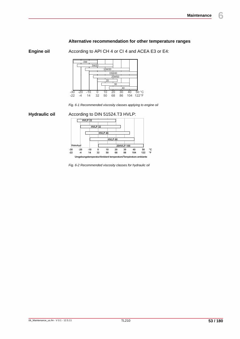
Alternative recommendation for other temperature ranges
Engine oil According to API CH 4 or CI 4 and ACEA E3 or E4:
Fig. 6-1 Recommended viscosity classes applying to engine oil
Hydraulic oil According to DIN 51524.T3 HVLP:
Fig. 6-2 Recommended viscosity classes for hydraulic oil
0W5W20
10W3015W40
20W5020
3040
Viskohyd
-20 -10 0 10 20 30 40 50 °C-30
-4 14 32 50 68 88 104 122 °F-22
Umgebungstemperatur/Ambient temperature/Température ambiante
HVLP 22
HVLP 32
HVLP 46
HVLP 68
20HVLP 100

TL210
Maintenance
54 / 180
6
06_Maintenance_us.fm - V 0.1 - 12.5.11
10
Fluid capacities
Tab. 6-6 Fluid capacities
Fluid capacities in liters/gallons
Fuels and lubricants
Fuel tank 240.0/63.4 Diesel fuel
Engine with oil filter 15.0/4.0 Engine oil (change quantity)
Hydraulic oil, tank, system, brakes 135.0*/35.7* Hydraulic oil
Hydraulic oil tank 95.0/25.1 Hydraulic oil (change quantity)
Front axle center housing 16.0/4.2 Transmission oil
Rear axle center housing 14.7/3.9 Transmission oil
Drive transmission 4.25/1.1 ATF mineral oil
Wheel hubs, front / rear axle 2.6/0.7 each Transmission oil
Coolant 41.0/10.8 Mixture of water, additives and glycol (50 / 50)
* The hydraulic oil quantity depends on the equipment level of the machine.
NoteAll values stated are approximate. The level marking is always the decisive factor. See chapter 5.2.2 "Front control console", page 36.

TL210
Maintenance
06_Maintenance_us.fm - V 0.1 - 12.5.11 55 / 180
6
10
6.5 LubricationProperty damage
Damaged grease nipples can cause machine damage.Check grease nipples for grease passing through.Replace damaged grease nipples immediately.
Lubricants The machine’s life expectancy and operating condition largely depend on the use of the specified lubricants and compliance with the service intervals.
If lubricants which do not conform to our recommendations are used, consequential damage may occur for which we will not assume liability, even inside the warranty period.
NoteThe intervals stated apply for single-shift operation.In case of special operating conditions, e.g. working on sandy soil, the lubrication intervals should be shortened, in order to achieve self-cleaning of bearing points.
NoteLubricate all lubrication points with multi-purpose grease. Grease specification: See chapter 6.4.2 "Consumables", page 50.

TL210
Maintenance
56 / 180
6
06_Maintenance_us.fm - V 0.1 - 12.5.11
10
6.5.1 Lubrication plan
Overview of lubrication points on machine
Fig. 6-3 Overview of lubrication points on machine
Tab. 6-7 Lubrication points on machine
4560_6001
5
4
8
7
2
1
3
6
Item Component Qty. Interval1 Lift cylinder – Front-end 2 Weekly
2 Lift frame – Front-end 2 Weekly
3 Steering cylinder – Rear-end 1 Weekly
4 Rear axle bearing 1 Weekly
5 Rear axle bearing 1 Weekly
6 Articulation 1 Weekly
7 Steering cylinder – Front-end 2 Weekly
8 Articulation 1 Weekly

TL210
Maintenance
06_Maintenance_us.fm - V 0.1 - 12.5.11 57 / 180
6
10
Overview of lubrication points on working attachment
Fig. 6-4 Overview of lubrication points on working attachment
Tab. 6-8 Lubrication points on working attachment
23
8
1
4
9
6
5
7
4560_6002
Item Component Qty. Interval1 Linkage – Bell crank 2 Weekly
2 Linkage – Rod 1 Weekly
3 Tilt control lever – Rod 1 Weekly
4 Bell crank – Lift frame 2 Weekly
5 Tilt control lever – Lift frame 1 Weekly
6 Lift cylinder – Lift frame 2 Weekly
7 Quick-attach system – Lift frame 2 Weekly
8 Linkage – Quick-attach system 2 Weekly
9 Tilt control lever – Tilt cylinder 1 Weekly

TL210
Maintenance
58 / 180
6
06_Maintenance_us.fm - V 0.1 - 12.5.11
10
6.6 Maintenance and Inspection PlanThe inspection plan lists all work that needs to be carried out on the wheel loader in regular intervals.
6.6.1 Daily tasksControl and maintenance work to be performed by the operating personnel (filling, cleaning, repairing, replacing if necessary):
Fig. 6-5 Daily and weekly tasks
4 6
3
14
14 15 17 14 13
16
2
4560_6004
18
11
1820 10
1213

TL210
Maintenance
06_Maintenance_us.fm - V 0.1 - 12.5.11 59 / 180
6
10
Tab. 6-9 Daily tasks
6.6.2 Tasks to be performed weeklyControl and maintenance work to be performed by the operating personnel (filling, cleaning, repairing, replacing if necessary):
Tab. 6-10 Tasks to be performed weekly
Item Inspection See1 Check the hydraulic oil level P. 85
2 Check the engine oil level P. 65
3 Check fuel level (fuel gauge in control console) P. 79
4 Check windshield washer fluid level
5 Visual inspection (general), e. g. for material cracks, external damage, completeness, etc.
6 Check whether there is water and/or dirt in the fuel line of the water separator and clean if necessary.
P. 83
7 Check for leaks in pipes, hoses, control unit, hydraulic pumps, cylinders, etc.The screw-in couplings must be locked when tightening hose or line connections to prevent rotation.
8 Check function of electrical indicating and warning elements as well as the lighting system P. 101
9 Check smooth movement of operating controls
10 Check V-belt tension
Item Inspection See11 Drain the fuel filter
12 Check the cooling fins of the combined coolerMachine damage due to strong accumulation of dustClean the combined cooler by hand
P. 71
13 Check correct function of door catches
14 Check tire pressure and tightness of wheel nuts
15 Check fastening of axles and propeller shaft
16 Check bearing bushings and pins/bolts of work equipment
17 Check pins/bolts, bushings, and the linkage assembly of the articulated steering
18 Check that pneumatic springs of engine hood function perfectly
19 Check function of brakes
20 Check if the dust filter for cab ventilation is dirty and clean if requiredMachine damage due to strong accumulation of dustShorten the inspection and cleaning intervals
21 Check function, condition and completeness of safety devices
22 Lubricate the machine according to overview of lubricating points P. 56

TL210
Maintenance
60 / 180
6
06_Maintenance_us.fm - V 0.1 - 12.5.11
10
6.6.3 Inspection plan machine
Work to be carried out by trained specialist dealer personnel:
NotePerform all inspection work at operating temperature of the machine.
Item Inspection Operating hours Seeo = Check, x = Replace af-
ter 100
ev-ery 500
ev-ery 1000
ev-ery 2000
min 2 x year
min.1 x year
1 Check machine for presence of machine-specific operating instructions
o o
2 Change the engine oil x x P. 66
3 Change the engine oil filter x x P. 67
4 Drain water from the fuel tank o o o P. 82
5 Replace the fuel filter x x P. 80
6 Check the air intake o o P. 74
7 Replace main air filter cartridge according to the service indicator x P. 76
8 Replace the air filter safety cartridge as required 1)
9 Check antifreeze level in coolant o P. 69
10 Change coolant x P. 70
11 Check V-belt tension o o P. 83
12 Check engine mount and pump attachment
o o
13 Check engine speed setting, upper and lower idle speeds
o o
14 Check valve lash on the engine and adjust if necessary
o o
15 Check injection valves every 5000 oh (I= 0.25, O = 0.50)
16 Check the crankcase ventilation system
o
17 Check acid level and battery connections
o o P. 99
18 Check condition of tires, tire pressure and fastening of wheel nuts
o o
19 Check fastening of axles and propeller shaft
o o
20 Check bearing bushings and pins/bolts of work equipment and adjust to "no play"
o o
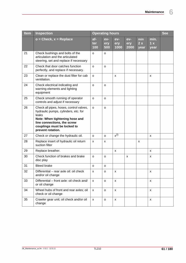
TL210
Maintenance
06_Maintenance_us.fm - V 0.1 - 12.5.11 61 / 180
6
10
21 Check bushings and bolts of the articulation and the articulated steering, set and replace if necessary
o o
22 Check that door catches function perfectly, and replace if necessary.
o o
23 Clean or replace the dust filter for cab ventilation.
o x x
24 Check electrical indicating and warning elements and lighting equipment
o o
25 Check smooth running of operator controls and adjust if necessary
o o
26 Check all pipes, hoses, control valves, hydraulic pumps, cylinders, etc. for leaksNote: When tightening hose and line connections, the screw couplings must be locked to prevent rotation.
o o
27 Check or change the hydraulic oil. o o x2) x
28 Replace insert of hydraulic oil return suction filter
x x x
29 Replace breather. x x
30 Check function of brakes and brake disc play
o o x x
31 Bleed brake o o
32 Differential – rear axle oil: oil check and/or oil change
x o x x
33 Differential – front axle: oil check and/or oil change
x o x x
34 Wheel hubs of front and rear axles; oil check or oil change
x o x x
35 Crawler gear unit; oil check and/or oil change
x o x x
Item Inspection Operating hours Seeo = Check, x = Replace af-
ter 100
ev-ery 500
ev-ery 1000
ev-ery 2000
min 2 x year
min.1 x year

TL210
Maintenance
62 / 180
6
06_Maintenance_us.fm - V 0.1 - 12.5.11
10
Tab. 6-11 Inspection plan machine
36 Lubricate the machine according to overview of lubricating points
o o
37 Check function, condition and completeness of safety devices
o o
38 Hydraulic function check with pressure function test
o o
39 Test run and test work. o o
40 Initial inspection card and return to manufacturer.
o o 3)
1)at least every 2 years2) Extension of oil change intervals according to Terexoil sample analysis and laboratory report. See chapter 6.3.1 "Regular oil analysis", page 47.3) within warranty
Item Inspection Operating hours Seeo = Check, x = Replace af-
ter 100
ev-ery 500
ev-ery 1000
ev-ery 2000
min 2 x year
min.1 x year

TL210
Maintenance
06_Maintenance_us.fm - V 0.1 - 12.5.11 63 / 180
6
10
6.7 Maintenance and inspection workPersonal injury
Eye injuries caused by parts flying around.Wear protective goggles during work.
Environmentally hazardous substancesEnvironmental damage caused by environmentally hazardous substances.
Do not allow oil oil to seep into the ground. Always place a receptacle for the collection of waste oil under the working area when draining oil or removing the filter insert.Collect waste oil and dispose of according to regulations!
NoteAll maintenance and inspection work must be performed acc. to the inspection plan. See chapter 6.6 "Maintenance and Inspection Plan", page 58.

TL210
Maintenance
64 / 180
6
06_Maintenance_us.fm - V 0.1 - 12.5.11
10
6.7.1 Display
The levels of engine oil, hydraulic oil and coolant can be read on the check display.
Checking the fluid levels
Fig. 6-6 Checking the fluid levels
Switch on the ignition.The symbols “hydraulic oil level” (1) and “coolant level” (2) light up for approx. 3 sec on the display.If the level is insufficient, the relevant level indicator lamp continues to light up.If required, top up the missing fluid.
NoteAll checks must be carried out with the machine standing on level ground and cooled down.
NoteWith the diesel engine running, the level indicator is without function!
12 km/hI
1 2
4560_6005
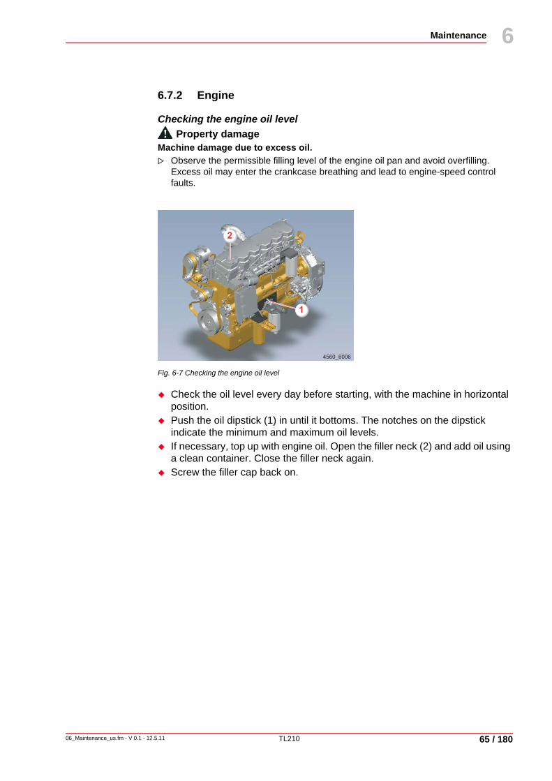
TL210
Maintenance
06_Maintenance_us.fm - V 0.1 - 12.5.11 65 / 180
6
10
6.7.2 Engine
Checking the engine oil levelProperty damage
Machine damage due to excess oil.Observe the permissible filling level of the engine oil pan and avoid overfilling. Excess oil may enter the crankcase breathing and lead to engine-speed control faults.
Fig. 6-7 Checking the engine oil level
Check the oil level every day before starting, with the machine in horizontal position. Push the oil dipstick (1) in until it bottoms. The notches on the dipstick indicate the minimum and maximum oil levels.If necessary, top up with engine oil. Open the filler neck (2) and add oil using a clean container. Close the filler neck again.Screw the filler cap back on.
4560_6006
1
2
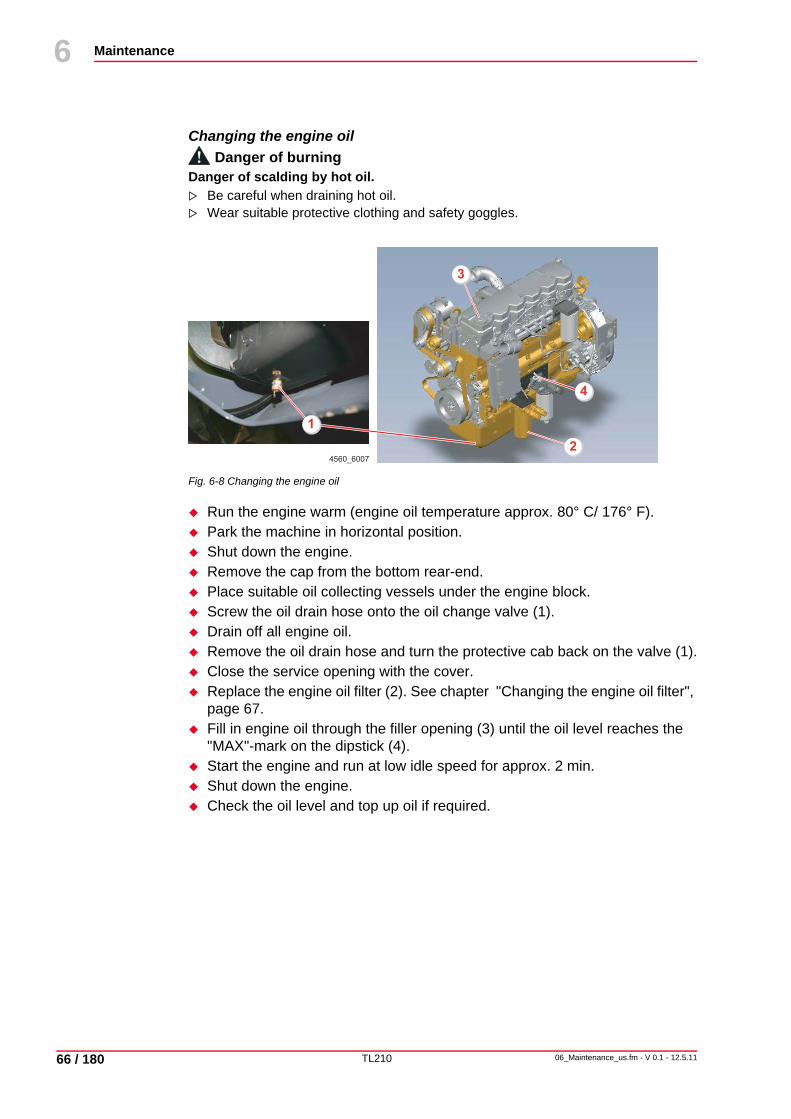
TL210
Maintenance
66 / 180
6
06_Maintenance_us.fm - V 0.1 - 12.5.11
10
Changing the engine oilDanger of burning
Danger of scalding by hot oil.Be careful when draining hot oil.Wear suitable protective clothing and safety goggles.
Fig. 6-8 Changing the engine oil
Run the engine warm (engine oil temperature approx. 80° C/ 176° F).Park the machine in horizontal position.Shut down the engine.Remove the cap from the bottom rear-end.Place suitable oil collecting vessels under the engine block.Screw the oil drain hose onto the oil change valve (1).Drain off all engine oil.Remove the oil drain hose and turn the protective cab back on the valve (1).Close the service opening with the cover.Replace the engine oil filter (2). See chapter "Changing the engine oil filter", page 67.Fill in engine oil through the filler opening (3) until the oil level reaches the "MAX"-mark on the dipstick (4).Start the engine and run at low idle speed for approx. 2 min.Shut down the engine.Check the oil level and top up oil if required.
4560_6007
1
2
3
4

TL210
Maintenance
06_Maintenance_us.fm - V 0.1 - 12.5.11 67 / 180
6
10
Changing the engine oil filter
Fig. 6-9 Changing the engine oil filter
The engine oil filter must be replaced every time the engine oil is changed.
Place suitable oil collecting vessels under the engine oil filter.Clean the outside of the engine oil filter.Unscrew the filter cartridge (1) using a commercially available tool.Check that the fastening stud is firmly secured in the filter head.Dispose of the filter cartridge environmentally.Check the condition of the filter head and clean it.Fill the new filter with oil.Wet the seal ring with oil and turn the cartridge on hand-tight.Remove oil contamination on the engine.Perform a test run and check the engine oil filter cartridge for leaks.
1
4560_6008

TL210
Maintenance
68 / 180
6
06_Maintenance_us.fm - V 0.1 - 12.5.11
10
6.7.3 Engine - cooling system
Combined hydraulic oil-water coolerDanger of burning
Danger of scalding by hot oil.Only open the radiator cap when the engine is cold.Wear suitable protective clothing and safety goggles.
Checking the coolant level
Fig. 6-10 Checking the coolant level
The coolant level is monitored automatically.
If the coolant level is insufficient, the coolant level indicator appears on the display as soon as the ignition is switched on. (1).
Top up coolant if the coolant level is insufficient.
12 km/hI
1
4560_6009
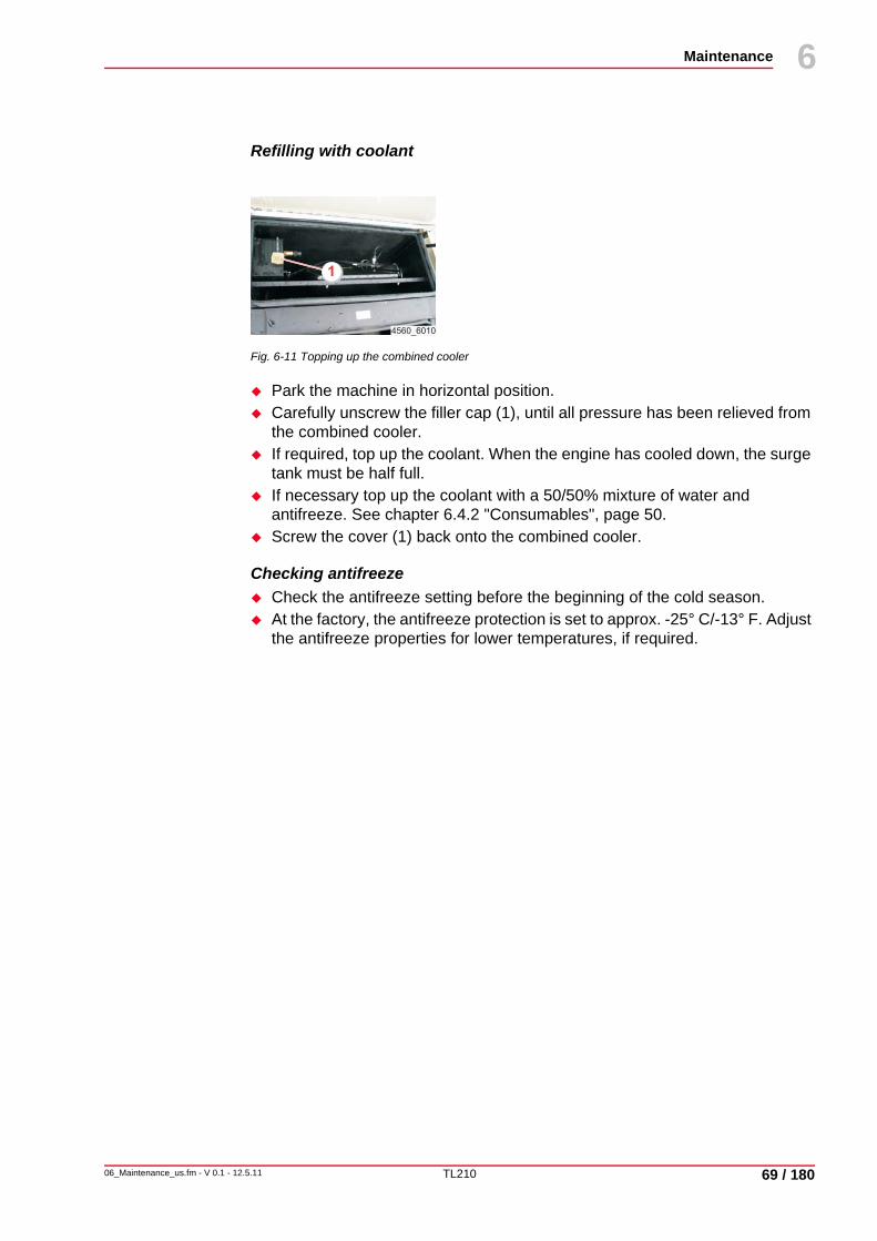
TL210
Maintenance
06_Maintenance_us.fm - V 0.1 - 12.5.11 69 / 180
6
10
Refilling with coolant
Fig. 6-11 Topping up the combined cooler
Park the machine in horizontal position.Carefully unscrew the filler cap (1), until all pressure has been relieved from the combined cooler.If required, top up the coolant. When the engine has cooled down, the surge tank must be half full.If necessary top up the coolant with a 50/50% mixture of water and antifreeze. See chapter 6.4.2 "Consumables", page 50.Screw the cover (1) back onto the combined cooler.
Checking antifreezeCheck the antifreeze setting before the beginning of the cold season.At the factory, the antifreeze protection is set to approx. -25° C/-13° F. Adjust the antifreeze properties for lower temperatures, if required.
L260-711L260-711
1
4560_6010

TL210
Maintenance
70 / 180
6
06_Maintenance_us.fm - V 0.1 - 12.5.11
10
Changing coolantDanger of scalding by hot oil.
Only open the radiator cap when the engine is cold.Wear suitable protective clothing and safety goggles.
Fig. 6-12 Changing coolant
Park the machine in horizontal position.Shut down the engine and allow the cooling system to cool down.Place a collecting vessel under the combined cooler.Carefully unscrew the filler cap (3), until all pressure has been relieved from the combined cooler.Remove the cap (3) from the combined cooler.Unscrew the water-drain plug (1) on the drain hose (2) and drain coolant.If necessary, flush the cooling system with water. Close the water-drain plug on the combined cooler again.Fill the cooling system with coolant and close the radiator cap. See chapter 6.4.2 "Consumables", page 50.Start the engine and run it until operating temperature is reached.Shut down the engine and let it cool down.Check the coolant level and top up coolant (if necessary, several times).
L260-711L260-711
1
2
3
4560_6011

TL210
Maintenance
06_Maintenance_us.fm - V 0.1 - 12.5.11 71 / 180
6
10
Cleaning the cooling fins in case of extreme exposure to dustProperty damage
Machine damage caused by overheating of engine and/or hydraulic oil.Clean the radiator carefully.Property damage
Machine damage due to strong accumulation of dust.Clean the cooler fins ahead of time to prevent overheating of the engine and/or the hydraulic oil.
Fig. 6-13 Engine cooler fan
1 Fan2 Hydrostatic transmission
The combined cooler features a fan (1) with hydrostatic drive (2).
NoteCollect the detergent and waste water in a suitable container and dispose of according to regulations!Ensure that no substances hazardous to waters come into contact with the soil or the water system.
4560_6012
1
2

TL210
Maintenance
72 / 180
6
06_Maintenance_us.fm - V 0.1 - 12.5.11
10
Automatically Switch the “motor cooling fan” switch to the forward switch position. The cooling fins are automatically cleaned at regular intervals.Due to the automatic reverse of the running direction of the fan, the dirt is removed from the cooling fins.
If there is increased exposure to dust, the cooler fins are subject to premature contamination:
Switch intermittently to the rear switch position in order to additionally clean the combined cooler. Subsequently return to the forward switch position.
Manually Switch the “motor cooling fan” switch to the rear switch position. The fan stops rotating. Then it runs for approx. 12 sec into the opposite direction. The dirt is removed from the cooling fins. The fan stops rotating. The switch is now in the center position.
Temperature-controlled
If the machine is used indoors (warehouses), switch the “motor cooling fan” switch to the center position. The fan does not reverse the direction of rotation.If required, clean the equipment manually in outdoor environments.
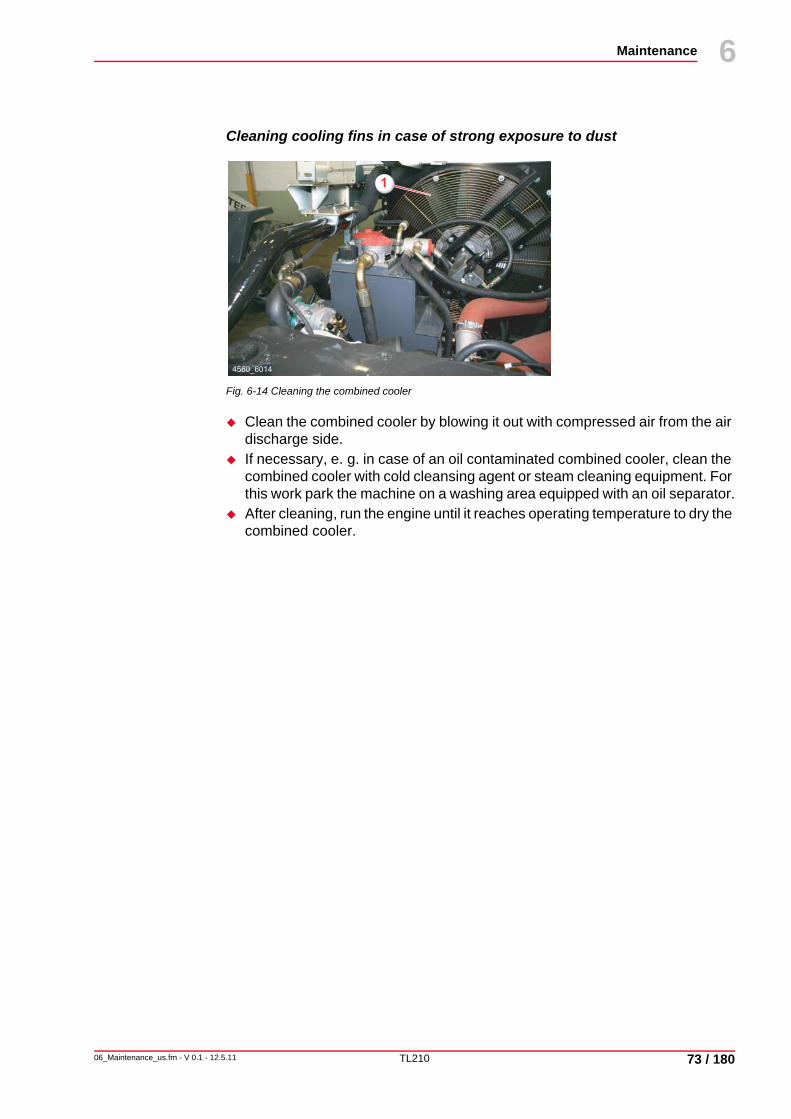
TL210
Maintenance
06_Maintenance_us.fm - V 0.1 - 12.5.11 73 / 180
6
10
Cleaning cooling fins in case of strong exposure to dust
Fig. 6-14 Cleaning the combined cooler
Clean the combined cooler by blowing it out with compressed air from the air discharge side.If necessary, e. g. in case of an oil contaminated combined cooler, clean the combined cooler with cold cleansing agent or steam cleaning equipment. For this work park the machine on a washing area equipped with an oil separator.After cleaning, run the engine until it reaches operating temperature to dry the combined cooler.
4560_6014
1

TL210
Maintenance
74 / 180
6
06_Maintenance_us.fm - V 0.1 - 12.5.11
10
6.7.4 Air intake systemProperty damage
Machine damage caused by dust being drawn into the engine.All maintenance work on the air intake system must be carried out with the engine shut down.Do not start the engine after the filter cartridge has been removed.Use only undamaged air filter cartridges.
Cleaning the dust ejection valve
Fig. 6-15 Cleaning the dust ejection valve
Dust ejection valves (1) are almost maintenance-free.
Remove possible dust deposits by pressing the valve together.
Checking the air intakeClean the air intake space in front of the air filter from any dirt (foliage, etc.).Check the air filter fastening for damage.Check the air channel after the air filter for leaks.Check the rubber parts for damage.Replace damaged parts immediately.
4560_6015
1

TL210
Maintenance
06_Maintenance_us.fm - V 0.1 - 12.5.11 75 / 180
6
10
Cartridge maintenance intervals
Replacing the air filter main cartridgeReplace the air filter main cartridge if the control light for filter maintenance in the control console lights up during operation.
Replacing the air filter safety cartridgeReplace the air filter safety cartridge:• after the third maintenance of the main cartridge• at the latest after 2 years of operation.• if the service indicator comes on again after the main cartridge has just
been serviced• if the main cartridge is damaged• if the safety cartridge is defective
NoteA brief delay in maintenance does not result in lower filter efficiency.

TL210
Maintenance
76 / 180
6
06_Maintenance_us.fm - V 0.1 - 12.5.11
10
Changing the main cartridge
Fig. 6-16 Changing the air filter cartridges
Release the wire fasteners (1) and remove the bottom of the housing (4).Withdraw the main cartridge (2) by twisting slightly to and fro.Check whether the safety cartridge (3) must be replaced.Mark the maintenance in the corresponding marking fields on the safety cartridge (3).Insert the new or cleaned main cartridge carefully into the filter housing starting with the open side and check that it is correctly positioned.Fit the lower part of the housing. (Pay attention to the position of the dust ejection valve).Place the wire fasteners in the groove of the flange on the filter housing and tighten.
NoteRemove the safety cartridge only in the case of necessary maintenance work. Only open the seal (5) of the safety cartridge for the purpose of replacement.
3
5
6
2
1
4
4560_6016

TL210
Maintenance
06_Maintenance_us.fm - V 0.1 - 12.5.11 77 / 180
6
10
Changing the safety cartridgeProperty damage
Machine damage due to damaged safety cartridge.Observe that the safety cartridge must not be cleaned and used again once it has been removed.
Fig. 6-17 Changing the air filter cartridges
Remove the main filter cartridge.Using a suitable tool (e.g. screwdriver), pierce the seal (5) of the safety cartridge (3) from the inside, then lift up the two clips (6).Grasp the safety cartridge (3) by the two clips (6) and withdraw by moving slightly to and fro. Dispose of the safety cartridge.Insert a new safety cartridge and check that it is correctly positioned.Re-install the main filter cartridge.
3
5
6
2
1
4
4560_6016

TL210
Maintenance
78 / 180
6
06_Maintenance_us.fm - V 0.1 - 12.5.11
10
Cleaning the main cartridgeProperty damage
Machine damage due to damaged main cartridge.Never wash or brush out the main cartridge.When blowing out, ensure that dust does not land on the inside of the main cartridge.Never continue to use damaged main cartridges. If in doubt, use a new one.
Fig. 6-18 Changing the air filter cartridges
The main cartridge can be cleaned up to five times if necessary. It must be replaced once it reaches its maximum service life of two years, at the latest. The number of times it is cleaned must be marked.
For cleaning (1), attach a pipe the end of which is bent at 90° to a compressed-air pistol. It must be sufficiently long to reach the floor of the cartridge. Blow out the main cartridge from the inside to the outside with dry compressed air (max. 5 bar/73 psi) by moving the pipe up and down in the cartridge and continue until no more dust escapes.Check the clean main cartridge for damage to the paper bellows and rubber seals (2). Tears and perforations in the paper bellows can be determined using a torch.
3
5
6
2
1
4
4560_6016

TL210
Maintenance
06_Maintenance_us.fm - V 0.1 - 12.5.11 79 / 180
6
10
6.7.5 Fuel systemDanger of injury
Personal injury due to excessive pressure while refueling.Open the fuel tank cap when topping up fuel using the electric refueling pump to avoid excessive pressure in the fuel tank!
Refueling
Fig. 6-19 Refueling
Check the fuel level (1) in the gauge.In order to prevent the formation of condensation water before the machine is put into operation the next time, top up fuel through the filler opening (2) every day after use.
4560_6018
UNIDECK
1
2

TL210
Maintenance
80 / 180
6
06_Maintenance_us.fm - V 0.1 - 12.5.11
10
Draining the fuel filter
Fig. 6-20 Draining the fuel filter
Open the fuel filter (1) on the water drain (2) until pure fuel escapes.Close the water drain.
1
2
4560_6020

TL210
Maintenance
06_Maintenance_us.fm - V 0.1 - 12.5.11 81 / 180
6
10
Replacing fuel filterProperty damage
Machine damage due to air in the filter.Before starting the engine, operate the fuel pump one minute to remove air from the filter.
Fig. 6-21 Replacing the fuel filter
Clean the fuel filter (1) and the outside of the fuel pre-cleaner (2).Open the water drain (3) on the filter bottom to drain fuel from the filter.Unscrew the filter housing (1+2) using commercially available tools and remove the filter housing along with the filter element from the filter flange.
NoteCollect the fuel in a suitable container and dispose of according to regulations!
NoteThe high pressure system must not be vented
4560_6021
1
3
2

TL210
Maintenance
82 / 180
6
06_Maintenance_us.fm - V 0.1 - 12.5.11
10
Draining water from the fuel tank
Fig. 6-22 Draining water from the fuel tank
Drain water from the fuel tank through the water-drain plug (1).Clean the filling screen filter (2) and check it for damage, replace if necessary.
4560_6023
1
2

TL210
Maintenance
06_Maintenance_us.fm - V 0.1 - 12.5.11 83 / 180
6
10
6.7.6 V-belt Danger of crushing
Body parts may be crushed by moving parts.Check or replace V-belts only when the engine is turned off.Secure the engine against unauthorized starting.
Checking the V-beltCheck the entire circumference of the V-belt for damage (visual inspection).Replace worn or damage V-belts immediately.
Checking V-belt tension
We recommend the use of a belt tensioner gauge in order to check the V-belt tension.
The tension check must be carried out according to the manufacturer’s manual.
Checking the V-belt tension without belt tensioner gaugePress the V-belt with your thumb in the middle of the longest free length, and measure the sagging. Using medium thumb pressure of approx. 45 N/10 lbf, the V-belt sag should equal 10 mm/0.4 in.
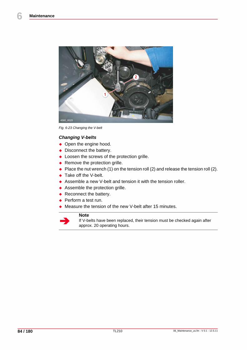
TL210
Maintenance
84 / 180
6
06_Maintenance_us.fm - V 0.1 - 12.5.11
10
Fig. 6-23 Changing the V-belt
Changing V-beltsOpen the engine hood.Disconnect the battery.Loosen the screws of the protection grille.Remove the protection grille.Place the nut wrench (1) on the tension roll (2) and release the tension roll (2).Take off the V-belt.Assemble a new V-belt and tension it with the tension roller.Assemble the protection grille.Reconnect the battery.Perform a test run.Measure the tension of the new V-belt after 15 minutes.
NoteIf V-belts have been replaced, their tension must be checked again after approx. 20 operating hours.
1
2
4560_6025

TL210
Maintenance
06_Maintenance_us.fm - V 0.1 - 12.5.11 85 / 180
6
10
6.7.7 Hydraulic oil tank
Checking the hydraulic oil level
Fig. 6-24 Checking the hydraulic oil level
The hydraulic oil level is monitored automatically.
If the hydraulic oil level is insufficient, the hydraulic oil level indicator appears on the display as soon as the ignition is switched on (1).
Check the hydraulic oil level every day with the machine standing on level ground.Top up hydraulic oil if the hydraulic oil level is insufficient. The oil level should be in the top third of the sight glass.
Topping up hydraulic oil
Fig. 6-25 Topping up hydraulic oil
Park the machine in horizontal position.Read off the hydraulic oil level on the sight glass (1) and, if required, top up hydraulic oil using the breather (2).The oil level should be in the top third of the sight glass (1).
12 km/hI
1
4560_6026
4560_6027
1
2

TL210
Maintenance
86 / 180
6
06_Maintenance_us.fm - V 0.1 - 12.5.11
10
Changing the hydraulic oilDanger of burning
Danger of scalding by hot oil.Be careful when draining hot oil.Wear suitable protective clothing and safety goggles.
Retract all hydraulic cylinders.Stop the engine.Remove the drain plug on the hydraulic oil tank and drain oil into a clean receptacle.
Remove ventilation filter (2), return filter (3) with filter head and suction filter (4).Clean filter head.Fit new filter.Turn the drain plug tightly back in.Fill up with clean hydraulic oil using the return filter (3); to do so, open the filter cover.Replace the cover of the return filter.
Fig. 6-26 Changing the hydraulic oil
NoteCollect the waste oil in a suitable container and dispose of in compliance with regulations.
4560_6032
4
2
3

TL210
Maintenance
06_Maintenance_us.fm - V 0.1 - 12.5.11 87 / 180
6
10
Replacing the hydraulic oil tank breathing filterProperty damage
Machine damage due to dirt reaching the uncovered hydraulic oil tank.Before starting, clean all parts above the tank.
Fig. 6-27 Replacing the hydraulic oil breathing filter
Remove the breathing filter (2) and dispose of according to regulations.
Fig. 6-28 Replacing the breathing filter
Clean the screen (3) and check for damage; replace if required.Screw in new breather (1) with O-ring (2) and tighten by hand.
NoteThe breathing filter must be replaced if it is soiled e.g. by oil mist.
4560_6032
4
2
3
4560_6033
1
2
3

TL210
Maintenance
88 / 180
6
06_Maintenance_us.fm - V 0.1 - 12.5.11
10
6.7.8 Hydraulic oil suction filterProperty damage
Machine damage due to dirt reaching the uncovered hydraulic oil tank.Before starting, clean all parts above the tank.
Changing the filter insert
Fig. 6-29 Changing the hydraulic oil suction filter
Shut down the engine.Open the breathing filter (1).Loosen the filter cover (2) of the suction filter with the aid of a tool.
NoteAfter a larger repair job, renew the filter cartridge following the test run.
NoteRemove the suction filter above a receptacle for the collection of waste oil.
4560_6028
2
1

TL210
Maintenance
06_Maintenance_us.fm - V 0.1 - 12.5.11 89 / 180
6
10
Fig. 6-30 Changing the filter insert of the suction filter
Remove the assembly (10) by turning and completely removing the filter cover, paying attention to the O-ring (3).Grasp the assembly by the filter cover (1) and unscrew the valve (2).Remove the filter insert and dispose of according to regulations.Clean the filter cover with centre rod (8) and the valve with diesel oil or benzine. While doing so, pay attention to the retaining plate (6) along with the seals (5), (7) and the compression spring (4).Check the O-ring (3) and seals (5), (7), (11) and replace any damaged part.Place surface “A” of the filter cover on a solid base, push a new filter insert onto the centre rod and fit onto the seal (5).Push the filter insert downward against the springs and tighten the valve (2) by hand.Slide the assembly (10) into the enclosure (12) and tighten the filter cover by hand. Ensure that the O-ring (3) is in exactly the right position.Screw back on the filter cover (1) and tighten by hand.Check the tightness of the filter by means of a test run.
4560_6029
1
3
9
2
5
4
7
12
11
6
8
10
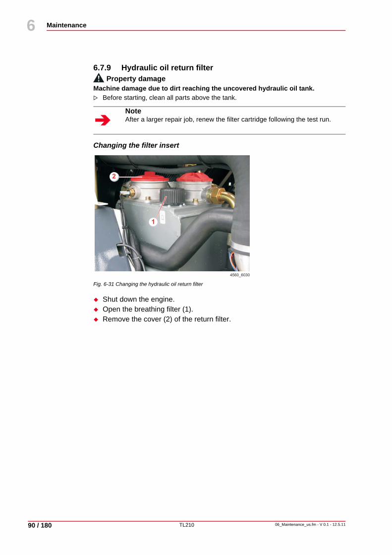
TL210
Maintenance
90 / 180
6
06_Maintenance_us.fm - V 0.1 - 12.5.11
10
6.7.9 Hydraulic oil return filterProperty damage
Machine damage due to dirt reaching the uncovered hydraulic oil tank.Before starting, clean all parts above the tank.
Changing the filter insert
Fig. 6-31 Changing the hydraulic oil return filter
Shut down the engine.Open the breathing filter (1).Remove the cover (2) of the return filter.
NoteAfter a larger repair job, renew the filter cartridge following the test run.
4560_6030
1
2
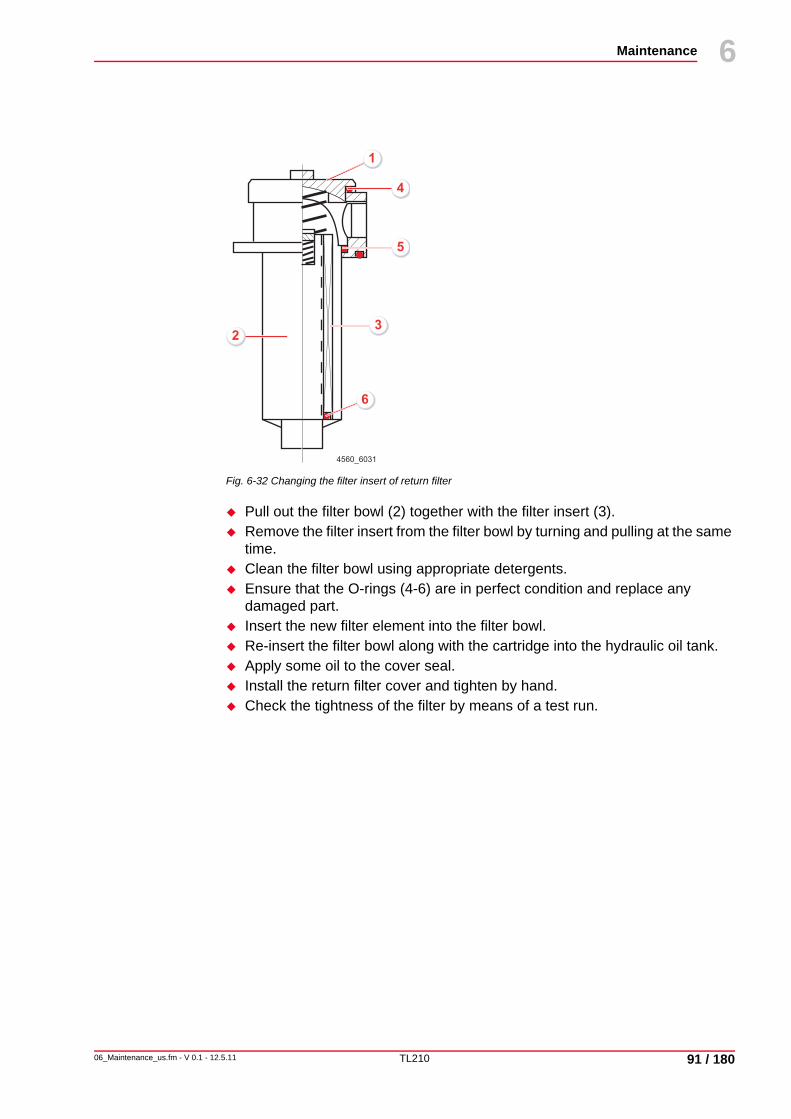
TL210
Maintenance
06_Maintenance_us.fm - V 0.1 - 12.5.11 91 / 180
6
10
Fig. 6-32 Changing the filter insert of return filter
Pull out the filter bowl (2) together with the filter insert (3).Remove the filter insert from the filter bowl by turning and pulling at the same time.Clean the filter bowl using appropriate detergents.Ensure that the O-rings (4-6) are in perfect condition and replace any damaged part.Insert the new filter element into the filter bowl.Re-insert the filter bowl along with the cartridge into the hydraulic oil tank.Apply some oil to the cover seal.Install the return filter cover and tighten by hand.Check the tightness of the filter by means of a test run.
4560_6031
1
32
5
4
6

TL210
Maintenance
92 / 180
6
06_Maintenance_us.fm - V 0.1 - 12.5.11
10
6.7.10 AxlesProperty damage
Machine damage due to insufficient oil in axles.After filling the axles with oil, move the machine for approx. 5 minutes to ensure that the oil is evenly distributed.After 5 minutes, check the oil level again, and top up if necessary.
NoteOnly change the axle oil when it is at operating temperature.
NoteCollect the waste oil in a suitable container and dispose of in compliance with regulations.
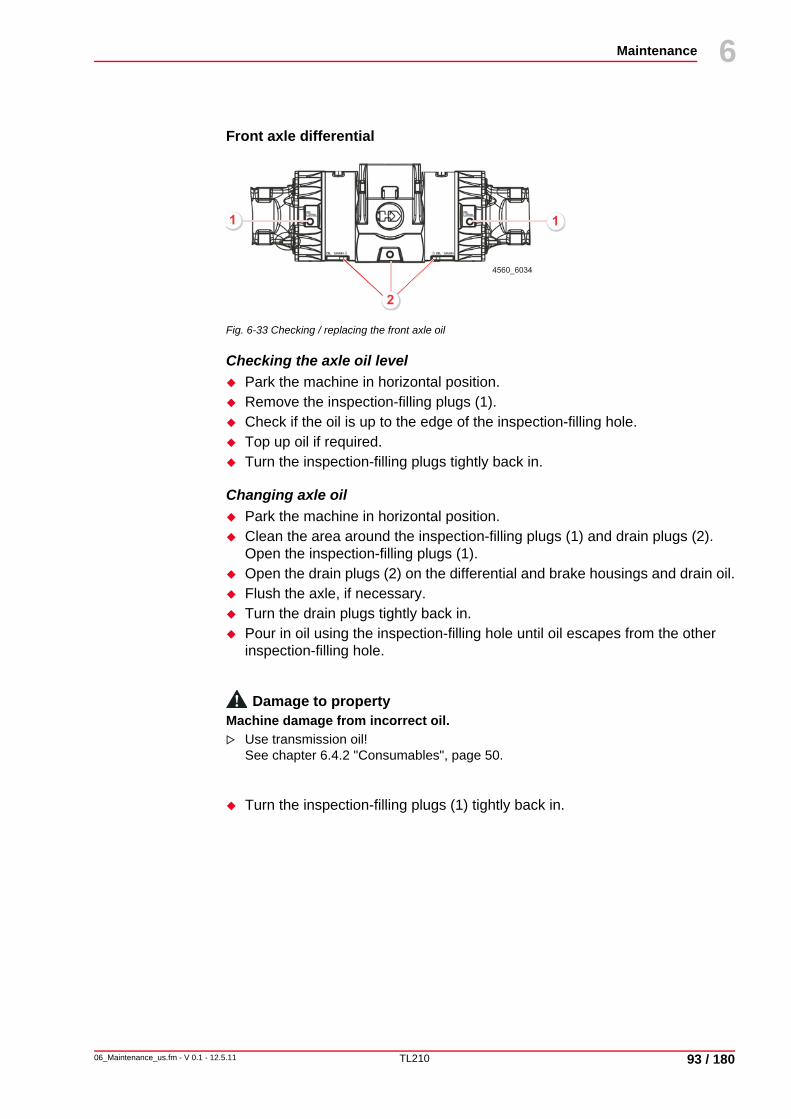
TL210
Maintenance
06_Maintenance_us.fm - V 0.1 - 12.5.11 93 / 180
6
10
Front axle differential
Fig. 6-33 Checking / replacing the front axle oil
Checking the axle oil levelPark the machine in horizontal position.Remove the inspection-filling plugs (1).Check if the oil is up to the edge of the inspection-filling hole.Top up oil if required.Turn the inspection-filling plugs tightly back in.
Changing axle oilPark the machine in horizontal position.Clean the area around the inspection-filling plugs (1) and drain plugs (2). Open the inspection-filling plugs (1).Open the drain plugs (2) on the differential and brake housings and drain oil.Flush the axle, if necessary.Turn the drain plugs tightly back in.Pour in oil using the inspection-filling hole until oil escapes from the other inspection-filling hole.
Damage to propertyMachine damage from incorrect oil.
Use transmission oil! See chapter 6.4.2 "Consumables", page 50.
Turn the inspection-filling plugs (1) tightly back in.
1 1
2
4560_6034
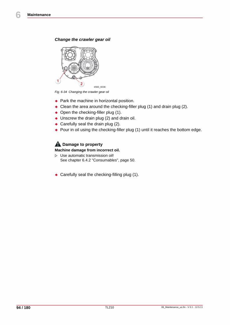
TL210
Maintenance
94 / 180
6
06_Maintenance_us.fm - V 0.1 - 12.5.11
10
Change the crawler gear oil
Fig. 6-34 Changing the crawler gear oil
Park the machine in horizontal position.Clean the area around the checking-filler plug (1) and drain plug (2).Open the checking-filler plug (1).Unscrew the drain plug (2) and drain oil.Carefully seal the drain plug (2).Pour in oil using the checking-filler plug (1) until it reaches the bottom edge.
Damage to propertyMachine damage from incorrect oil.
Use automatic transmission oil! See chapter 6.4.2 "Consumables", page 50.
Carefully seal the checking-filling plug (1).
4560_6036
12
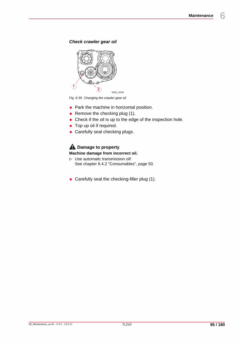
TL210
Maintenance
06_Maintenance_us.fm - V 0.1 - 12.5.11 95 / 180
6
10
Check crawler gear oil
Fig. 6-35 Changing the crawler gear oil
Park the machine in horizontal position.Remove the checking plug (1).Check if the oil is up to the edge of the inspection hole.Top up oil if required.Carefully seal checking plugs.
Damage to propertyMachine damage from incorrect oil.
Use automatic transmission oil! See chapter 6.4.2 "Consumables", page 50.
Carefully seal the checking-filler plug (1).
4560_6036
12
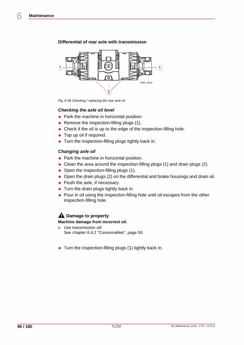
TL210
Maintenance
96 / 180
6
06_Maintenance_us.fm - V 0.1 - 12.5.11
10
Differential of rear axle with transmission
Fig. 6-36 Checking / replacing the rear axle oil
Checking the axle oil levelPark the machine in horizontal position.Remove the inspection-filling plugs (1).Check if the oil is up to the edge of the inspection-filling hole.Top up oil if required.Turn the inspection-filling plugs tightly back in.
Changing axle oilPark the machine in horizontal position.Clean the area around the inspection-filling plugs (1) and drain plugs (2).Open the inspection-filling plugs (1).Open the drain plugs (2) on the differential and brake housings and drain oil.Flush the axle, if necessary.Turn the drain plugs tightly back in.Pour in oil using the inspection-filling hole until oil escapes from the other inspection-filling hole.
Damage to propertyMachine damage from incorrect oil.
Use transmission oil! See chapter 6.4.2 "Consumables", page 50.
Turn the inspection-filling plugs (1) tightly back in.
1 1
2
4560_6034

TL210
Maintenance
06_Maintenance_us.fm - V 0.1 - 12.5.11 97 / 180
6
10
Wheel hub
Fig. 6-37 Checking and replacing oil
Checking wheel hub oil levelTurn the wheel to the filling and inspection position; the screw plug must be horizontal (1).Remove the screw plug (1).Check if the oil is up to the edge of the screw plug.Top up oil if required.Turn the screw plug tightly back in.
Changing axle oilTurn the wheel until the screw plug on the hub is at the bottom (drain position (2)).Unscrew the screw plug and catch running out oil.Flush, if necessary.Turn the wheel to the filling and inspection position; the screw plug must be horizontal (1).Fill in oil up to the lower edge of the screw plug.
Damage to propertyMachine damage from incorrect oil.
Use transmission oil! See chapter 6.4.2 "Consumables", page 50.
Turn the screw plug tightly back in.
NoteThe wheel hub has a combined inspection, filling and drain plug!
4560_60382
1
TL210
Maintenance
98 / 180
6
06_Maintenance_us.fm - V 0.1 - 12.5.11
10
6.7.11 Wheels
Checking the tire pressureCheck the air pressure in accordance with the pressure chart. See chapter 9.3.2 "Pressure chart", page 162.
Checking the tightness of wheel nutsDuring the first 50 operating hours, check the tightness of the wheel nuts (M 22 x 1.5) daily and subsequently every week, and tighten to the correct torque if necessary.When fitting a wheel, tighten the nuts to the correct torque crosswise in several stages.
NoteNote that the tightening torque of 610 Nm/450 lbf ft applies to the wheel nuts M 22 x 1.5.

TL210
Maintenance
06_Maintenance_us.fm - V 0.1 - 12.5.11 99 / 180
6
10
6.7.12 Electrical equipment
BatteryDanger of explosion
Death, burns or blindness due to explosive gases or contact with corrosive acids.Keep electrical arcs, sparks, open fire and smoldering tobacco away.Wear protective clothing.
The two batteries are located in the rear-end below the engine hood, behind the left-hand wheelhouse.
Fig. 6-38 Checking the battery
Checking the battery
Shut down the engine.The acid level should be approximately 10 mm/0.4 in above the plate edges. If necessary, top up with distilled water.For maintenance-free batteries, this check is not necessary.
NoteFollow the instructions of the battery manufacturer when taking a battery into service for the first time.
NoteFor maintenance-free batteries, this check is not necessary.
3
12
4560_6039

TL210
Maintenance
100 / 180
6
06_Maintenance_us.fm - V 0.1 - 12.5.11
10
Removing batteries
Fig. 6-39 Removing batteries
Turn off the battery main switch (1).
Damage to persons and propertyRisk of accident due to incorrect operation.
The battery isolator switch must never be pressed when the engine is running.After switching off the engine, wait 2 minutes before pressing the battery isolator switch because the engine control unit needs this time to store errors.Non-observance may result in damage to the engine control unit.
First disconnect the ground cable (2) on battery 1 (66), then the positive cable (3) on battery 2 (7).Remove the connecting cable (4).Loosen the clamping angle (5; 2 brackets on each battery side).Lift out the battery.
4560_6040
1
4
7
6
3
4
2
5

TL210
Maintenance
06_Maintenance_us.fm - V 0.1 - 12.5.11 101 / 180
6
10
Installing batteriesProperty damage
Machine damage caused by reversing the terminals.Connect the minus terminal with the minus pole and the plus terminal with the plus pole.
Place both batteries into the machine.Attach the batteries using a clamping bracket (5) for each battery.Attach the connecting cable (4): Connect the positive terminal (+) of battery 1 (6) with the negative terminal (-) of battery 2 (6).Connect the positive cable (3) to the positive terminal (+) of battery 2 (7).Connect the ground cable (2) to the negative terminal (-) of battery 1 (6).Pay attention to a good charge condition of the battery, especially in winter.
Checking the lighting and warning equipmentCheck the function of the lighting equipment. Check the function of the control lights. Check the function of the warning equipment.

TL210
Maintenance
102 / 180
6
06_Maintenance_us.fm - V 0.1 - 12.5.11
10
6.7.13 Cab ventilation dust filterThe air intake for the heater and fresh air supply of the cab features a dust filter, optionally a charcoal/ pollen filter.
Removing the dust filter for cab ventilation
Fig. 6-40 Removing the dust filter for cab ventilation
Remove the ventilation grate (1).Remove the angle bracket (2).Remove the dust filter (3).Clean the filter or replace it.
Cleaning the dust filter for cab ventilation
Knock the filter with the intake side (side covered by expanded metal) several times on a flat and hard surface.Using dry compressed air (max. 5 bar/73 psi), blow against the direction of flow.Check the filter for damage to the paper bellows and seal.
NoteNever wash or brush out the filter.Never continue to use damaged dust filters!
4560_6042
1
2
3
TL210
Maintenance
06_Maintenance_us.fm - V 0.1 - 12.5.11 103 / 180
6
10
Installing the dust filter for cab ventilation
Insert new or cleaned dust filter until the stop.Fasten the dust filter with the angle bracket.Attach the ventilation grate.
NoteObserve the mounting position of the dust filter; the air flow arrows must point towards the cab.
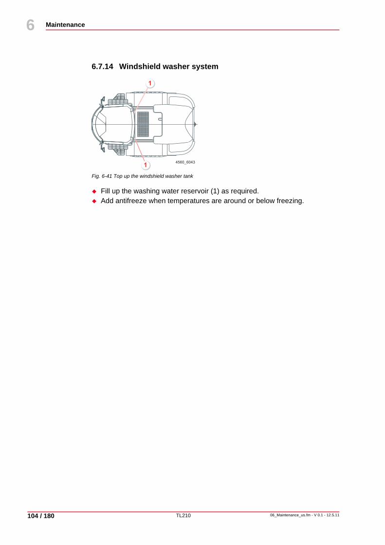
TL210
Maintenance
104 / 180
6
06_Maintenance_us.fm - V 0.1 - 12.5.11
10
6.7.14 Windshield washer system
Fig. 6-41 Top up the windshield washer tank
Fill up the washing water reservoir (1) as required.Add antifreeze when temperatures are around or below freezing.
4560_60431
1
TL210
Maintenance
06_Maintenance_us.fm - V 0.1 - 12.5.11 105 / 180
6
10
6.8 Taking out of service
6.8.1 Preservation (temporary immobilization )Property damage
Machine damage caused by bearing defects (e. g. corrosion damage) during shutdown periods over three months.
Preserve the machine.
Preserving the machineWe recommend keeping the machine in a dry, dust-free room during the storage period.Thoroughly clean the inside and outside of the machine, including the engine.Lubricate the machine by following the lubrication plan. See chapter 6.5.1 "Lubrication plan", page 56.Check and top up all oil levels in components like engine, gearbox, etc.Check and top up the hydraulic oil level.Repair paint damage.Fill the diesel fuel tank completely to avoid wall corrosion.Check the antifreeze properties of the coolant and adapt these, if necessary.Apply all preservation measures as specified in the operating instructions for the engine.Check the tire pressure according to the prescribed value and protect the tires from direct sunlight.Treat bare piston rods with a commercially available corrosion protection agent.Remove the battery, clean it and store it properly in a dry and, over winter, in a frost-free room. Cover the poles with pole grease.Close the air intake openings of the air filter system and the exhaust outlet on the exhaust pipe.Check whether there are special procedures from CUMMINS.
TL210
Maintenance
106 / 180
6
06_Maintenance_us.fm - V 0.1 - 12.5.11
10
6.8.2 While being taken out of service
Running the movementsBeforehand, the anti-corrosion coat must be removed from the piston rods, and the openings of the air filter system and the exhaust pipe freed. When the machine is out of use for 6 months, after this time all assemblies must be brought to operating temperature and maneuvered for approx. 15 minutes.Renew the preservation after the movement test.
6.8.3 After the machine had been taken out of serviceBefore putting the machine into operation once more, the following measures must be carried out:
Taking the machine back into serviceClean the piston rods from the corrosion protection coating. Clear the air intake of the air filter and the exhaust opening.Check the condition of main air filter element and safety cartridge, replace if necessary.Wash the machine with a neutral cleansing agent.Check the battery, recharge if necessary and install it.Carry out all measures for putting the diesel engine back into operation listed in the Engine Operating Manual.If the machine has been out of use for more than 6 months, the oil in the assemblies such as engine, gearbox, etc. must be changed.After a downtime of six month or more replace the hydraulic filters(pressure, return flow, and breathing filter, if applicable).Lubricate the machine by following the lubrication plan. See chapter 6.5.1 "Lubrication plan", page 56.
6.8.4 DisposalDamage to persons and property
If the machine is not correctly disposed of at the end of its working life, accidents and environmental damage may result.
Arrange for the machine to be disposed of by a suitable disposal company only.TEREX recommends returning the machine to a TEREX dealer.

TL210
Operation
07_Operation_us.fm - V 0.1 - 12.5.11 109 / 180
7
14
7 Operation
7.1 Before operationDamage to persons and property
Danger of accident caused by wrong actuation and uncontrolled machine movements.
Become familiar with all display and control elements before starting excavating. See chapter 5.2.1 "Operating controls", page 35.
The chapter "Operation" describes all functions for operating the wheel loader.
The machine must be entered from the left-hand side as seen in the direction of travel.The right-hand cab door acts as an emergency exit. If the cab is entered by the right-hand door, the joystick may be operated unintentionally.Become familiar with the display and control elements before driving or starting work. See chapter 5.2 "Display elements and operating controls in operator's stand", page 35.Familiarize yourself with the control levers and pedals. See chapter 5.2 "Display elements and operating controls in operator's stand", page 35.Thoroughly inspect the wheel loader visually before each start-up. Watch out for damage, loose or missing screws, oil deposits, oil or fuel leaks. Any faults must be immediately rectified. If the operational safety of the wheel loader is at risk, you must only start operation after the faults have been eliminated.
NoteStrictly observe all safety notes.See chapter 3.6 "Operation", page 20.
NoteInitial inspection must be carried out before commissioning. See chapter 6.6 "Maintenance and Inspection Plan", page 58.

TL210
Operation
110 / 180
7
07_Operation_us.fm - V 0.1 - 12.5.11
14
7.1.1 Adjustments
Adjusting the driver's seat
The comfort seat is spring-mounted with oil-pressure operated shock absorbers and lap belt.
The seat meets international quality and safety standards in compliance with ISO 7096 and ISO 6683.
Fig. 7-1 Adjusting the driver's seat
Operate the horizontal adjustment (6) to move the seat to the position most convenient for you.The driver's weight can be adjusted for in 9 stages (22.05 lb each). Swing the weight adjustment handle (7) to the right against the stop. The weight adjustment automatically changes to pos. 50 kg/110 lbs.Adjust the backrest with the inclination adjustment (5) to the desired inclination.Adjust the backrest with the backrest adjustment (4) to the desired inclination.Armrest (3) (option)Vertical adjustment (2):• Raising seat: Raise seat until it clicks audibly into place.• Lowering seat: Raise seat as far as the stop; the seat then sinks to its
lowest position.Position adjustment (1):• Adjustment to the front: Slide the seat forward.• Adjustment to the back: Slide the seat backward.
4
7
6
5
1
3
2
4560_5010

TL210
Operation
07_Operation_us.fm - V 0.1 - 12.5.11 111 / 180
7
14
Steering wheel adjustment
Fig. 7-2 Steering wheel adjustment
Tilt adjustment of steering wheel:
Push the locking lever (1) down.Adjust steering-wheel tilt.Release the locking lever.
Steering wheel height adjustment:
Pull the locking lever (1) up.Adjust steering-wheel height.Release the locking lever.
UNIDECKUNIDECK
P
- +
HAZARD
P
AUTO OFF
0I
4560_7001
1

TL210
Operation
112 / 180
7
07_Operation_us.fm - V 0.1 - 12.5.11
14
Adjusting heating, ventilation and air-conditioningThe air-conditioning unit should be switched on for approx. 5 minutes at least once a month to lubricate the compressor seals.After switching on the air-conditioning system, open the windows 2-3 minutes to allow the hot air (stored heat) to escape.Keep windows and doors closed.
Fig. 7-3 Button assignment of operator control panel Heating, ventilation and air-conditioning
Cooling (10) If the LED below the button lights up (10), cooling is ON. If the LED does not light up, cooling is OFF.
Circulating air (9)
If the LED under the button lights up (9), recirculation mode is activated. If the LED does not light up, fresh air mode is activated.
Display (3) The display (3) shows the relevant temperatures or trouble codes in case of malfunction.
Fan (4) The LEDs in the fan symbol indicate the momentary fan speed.
NoteIt is recommended to cool down the vehicle interior temperature by no more than 6° C/42.8° F to 8° C/44.6° F below outside temperature.
AUTO OFF
11 10 9 8
3 4
52
1 6
7
4560_5006

TL210
Operation
07_Operation_us.fm - V 0.1 - 12.5.11 113 / 180
7
14
Fig. 7-4 Button assignment of operator control panel Heating, ventilation and air-conditioning
Adjusting the fan speedPress the button (5).The fan speed increases by one step.Press the button (6).
The fan speed decreases by one step.
The type and the version of the air-conditioning unit are displayed on the screen. Release the button (11).
Performing automatic diagnosis
To this purpose, the engine cover should be closed and the engine itself be at operating temperature. The outside temperature should be between 15° C/59° F and 30° C/86° F. The air-conditioning system should be ON.
Hold the button (11) depressed.The air-conditioning unit performs an automatic diagnosis.
Displaying interior/exterior temperaturePress the button (7).The cab temperature is measured by the interior temperature sensor (8). The inside temperature is shown on the display (3) for approx. 6 sec. If the air-conditioning unit is in cooling-air mode, the outside temperature is shown on the display (3) for approx. 6 sec by pressing the button (7).
Setting the temperaturePress the button (2).The temperature increases by 1° C/33.8° F.Press the button (1).The temperature decreases by 1° C/33.8° F.
AUTO OFF
11 10 9 8
3 4
52
1 6
7
4560_5006
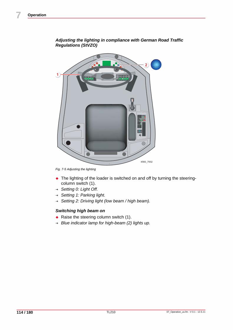
TL210
Operation
114 / 180
7
07_Operation_us.fm - V 0.1 - 12.5.11
14
Adjusting the lighting in compliance with German Road Traffic Regulations (StVZO)
Fig. 7-5 Adjusting the lighting
The lighting of the loader is switched on and off by turning the steering-column switch (1).Setting 0: Light Off.Setting 1: Parking light.Setting 2: Driving light (low beam / high beam).
Switching high beam onRaise the steering column switch (1). Blue indicator lamp for high-beam (2) lights up.
UNIDECKUNIDECK
P
- +
HAZARD
P
AUTO OFF
0I
4560_7002
1
2

TL210
Operation
07_Operation_us.fm - V 0.1 - 12.5.11 115 / 180
7
14
7.2 OperationDanger to life
Physical injury caused by machine movements. Before starting the engine, take care to ensure that no one is in the immediate vicinity of the wheel loader or in the danger zone.
Damage to persons and propertyDanger of accident caused by wrong actuation and uncontrolled machine movements.
Start at low engine speed when familiarizing yourself with the controls.
Immobilizer (option)
Set the start switch key to position "0."The immobilizer is automatically activated after 5 sec. The immobilizer becomes and remains activated if the key remains inserted in position “0”.
Deactivating the immobilizer
Set the start switch key to position “1”.The transponder is not read until the mechanical key in the start switch has activated terminal 15. This makes it necessary to first open the mechanical locking system before the electronic key is inspected. A manipulation of the immobilizer with the ignition deactivated is thereby impossible.
Learning a new key
Learning a new key takes place with a master key that is identified with a red key pommel.
The master key must be stored carefully; only one master key is available for each immobilizer.
This master key can only be used to learn new keys; it cannot be used to deactivate the immobilizer. This prevents the master key from being used to operate the vehicle.
Insert the master key into the ignition lock.Set the master key in position "1" (terminal 15 on) for max. 5 sec. Set the master key in position “0” (terminal 15 off).
NoteThe immobilizer is self-activating; that is, without additional activation or divergent actions.
If the mechanical start switch is in position "0" (terminal 15 off), the immobilizer is generally activated.
NoteThe immobilizer is deactivated if a valid mechanical key and a valid electronic key (transponder) are present.

TL210
Operation
116 / 180
7
07_Operation_us.fm - V 0.1 - 12.5.11
14
Pull out the master key.The immobilizer electronics expects the key that is to be learned in the next 15 sec. Insert the key to be learned into the ignition lock.Turn the key to be learned to position “1”. The learned key is registered as a valid key.
If no key is recognized for learning in 15 sec, the learning procedure ends automatically.
Learning multiple new keysInsert the keys to be learned into the ignition lock one after the other.Turn the key to be learned to position “1”.Leave the individual keys in the position "1" for at least 1 sec.
Up to 10 keys can be learned.
With this technique, it is possible to learn one key on several immobilizers, such as for a general fleet key.
Clearing learned keys
Clearing learned keys is necessary if a learned key has been lost.
All learned keys are cleared during the deletion process. After clearing, all available keys can be relearned.
Insert the master key into the ignition lock.Set the master key in position “1” (terminal 15 on) for minimum 20 sec. All learned keys are cleared and all available keys can be relearned.The master key code is not deleted during the clearing process.
NoteThis function is only available if the control unit relay is additionally connected to terminal 30.
NoteThis function is only available if the control unit relay is additionally connected to terminal 30.

TL210
Operation
07_Operation_us.fm - V 0.1 - 12.5.11 117 / 180
7
14
Security functions
If more than 5 keys are activated in the ignition lock within 1 minute with different invalid codes, the immobilizer remains active for 15 minutes and accepts no valid keys during this time.
This procedure prevents the "testing" of different keys and the coincidental locating of the correct key.
If different invalid keys are recognized without the ignition lock being brought to position "0," the immobilizer remains activated for 15 minutes and accepts no valid keys.
Valid keys are only accepted after the 15 minutes and recognition of the start switch in the "0" position. This prevents the key from being tested without the mechanical ignition lock being activated, such as if the ignition lock is forcibly brought to the "1" position.
Malfunctions
NoteFault causes and their resolution See chapter 10.3.1 "Immobilizer faults", page 172.
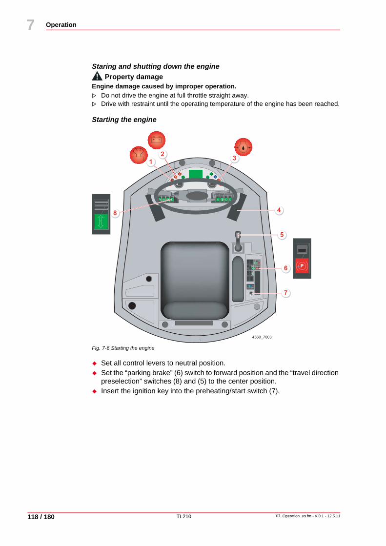
TL210
Operation
118 / 180
7
07_Operation_us.fm - V 0.1 - 12.5.11
14
Staring and shutting down the engineProperty damage
Engine damage caused by improper operation.Do not drive the engine at full throttle straight away. Drive with restraint until the operating temperature of the engine has been reached.
Starting the engine
Fig. 7-6 Starting the engine
Set all control levers to neutral position.Set the “parking brake” (6) switch to forward position and the “travel direction preselection” switches (8) and (5) to the center position.Insert the ignition key into the preheating/start switch (7).
UNIDECKUNIDECK
P
- +
HAZARD
P
AUTO OFF
0I
4560_7003
3
48
5
7
6
1
2
P
- +

TL210
Operation
07_Operation_us.fm - V 0.1 - 12.5.11 119 / 180
7
14
Switch on ignition and wait for approx. 5 sec.
The control lights for “Pre-heating monitor” (1), “Charge Control” (2) and “Engine Oil Pressure” (3) light up.Once the “Preheating” (1) control light has gone out, turn the ignition key to “START”. As soon as the engine is running, turn the ignition key back to Position "1" and decrease the revs to low idle speed. The indicator lamps should go out.If the engine does not start after max. 20 seconds, return the ignition key to position "1" or "0".Repeat the starting procedure at the earliest after 1 minute.If the engine does not start after 2 attempts, perform trouble shooting.
NoteThe display establishes the internal readiness for operation. As a result, all indicator lamps are briefly activated for a functional check.
UNIDECKUNIDECK
P
- +
HAZARD
P
AUTO OFF
0I
4560_7003
3
48
5
7
6
1
2
P
- +

TL210
Operation
120 / 180
7
07_Operation_us.fm - V 0.1 - 12.5.11
14
Shutting down the engine
Turn the ignition key to position "0". The engine stops automatically.
NoteDo not shut down the engine all of a sudden from full load, but let it idle without load for a while.
TL210
Operation
07_Operation_us.fm - V 0.1 - 12.5.11 121 / 180
7
14
7.2.1 Monitoring the machine during operationProperty damage
Engine damage due to fault which has not been remedied.The fault must be remedied before restarting the engine and operating the machine again.
Action to be taken if the control lights for charge control or engine oil pressure light up
Shut down the engine immediately and perform trouble shooting.Call for service personnel, if necessary.
Action to be taken if the control light for air filter contamination lights upPerform the necessary air filter maintenance.
Action to be taken if the permitted coolant temperature is exceededStop work.Open the engine hood and run the engine with idle speed to cool it down. Shut down the engine after it has cooled down and perform trouble shooting.Call for service personnel, if necessary.
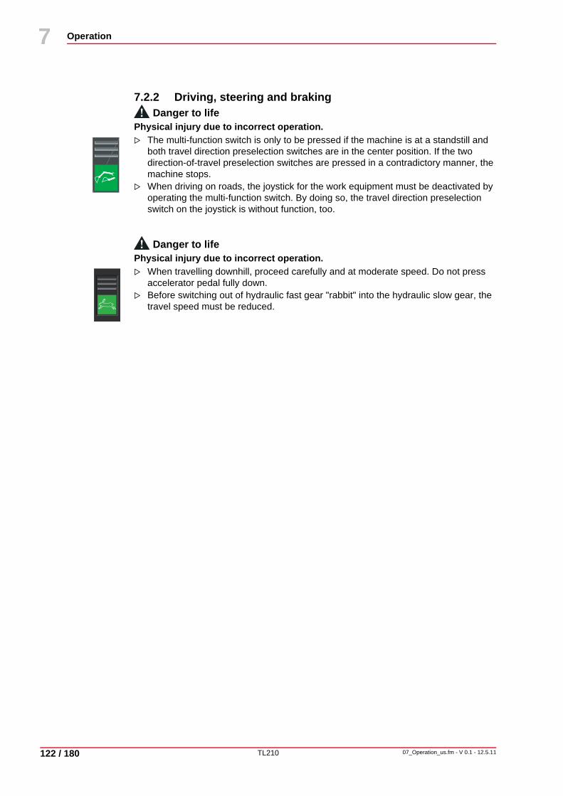
TL210
Operation
122 / 180
7
07_Operation_us.fm - V 0.1 - 12.5.11
14
7.2.2 Driving, steering and brakingDanger to life
Physical injury due to incorrect operation. The multi-function switch is only to be pressed if the machine is at a standstill and both travel direction preselection switches are in the center position. If the two direction-of-travel preselection switches are pressed in a contradictory manner, the machine stops.When driving on roads, the joystick for the work equipment must be deactivated by operating the multi-function switch. By doing so, the travel direction preselection switch on the joystick is without function, too.
Danger to lifePhysical injury due to incorrect operation.
When travelling downhill, proceed carefully and at moderate speed. Do not press accelerator pedal fully down.Before switching out of hydraulic fast gear "rabbit" into the hydraulic slow gear, the travel speed must be reduced.

TL210
Operation
07_Operation_us.fm - V 0.1 - 12.5.11 123 / 180
7
14
Driving
Fig. 7-7 Driving and steering
The machine has two preselection switches for travel direction (2) and (3) which are alternately active. One preselection switch for travel direction (2) is located on the control console at the front and another such switch on the joystick (3) controlling the working hydraulics.
Adjusting the travel direction with working hydraulics activatedSet the multi-function switch (1) to the front position.The "travel direction preselection" (2) switch is deactivated.The "travel direction preselection" (3) switch is activated.Set the travel direction on the “travel direction preselection” (3) switch.
Adjusting the travel direction with working hydraulics disabledSet the multi-function switch (1) to the rear position.The "travel direction preselection" (3) switch is deactivated.The "travel direction preselection" (2) switch is activated.Set the travel direction on the “travel direction preselection” (2) switch.
UNIDECKUNIDECK
P
- +
HAZARD
P
AUTO OFF
0I
4560_7004
3
1
2
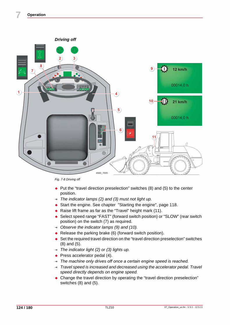
TL210
Operation
124 / 180
7
07_Operation_us.fm - V 0.1 - 12.5.11
14
Driving off
Fig. 7-8 Driving off
Put the “travel direction preselection” switches (8) and (5) to the center position.The indicator lamps (2) and (3) must not light up.Start the engine. See chapter "Starting the engine", page 118.Raise lift frame as far as the “Travel” height mark (11).Select speed range “FAST” (forward switch position) or “SLOW” (rear switch position) on the switch (7) as required.Observe the indicator lamps (9) and (10).Release the parking brake (6) (forward switch position).Set the required travel direction on the “travel direction preselection” switches (8) and (5).The indicator light (2) or (3) lights up.Press accelerator pedal (4). The machine only drives off once a certain engine speed is reached.Travel speed is increased and decreased using the accelerator pedal. Travel speed directly depends on engine speed.Change the travel direction by operating the “travel direction preselection” switches (8) and (5).
UNIDECKUNIDECK
P
- +
HAZARD
P
AUTO OFF
0I
4560_7005
5
6
4
8
2
1
3
7 12 km/h
00014,0 h
I
21 km/h
00014,0 h
III10
11
9
P

TL210
Operation
07_Operation_us.fm - V 0.1 - 12.5.11 125 / 180
7
14
Coming to a halt
Fig. 7-9 Coming to a halt
Reduce the travel speed by releasing the accelerator pedal (2).The hydrostatic travel drive acts as a non-wearing auxiliary brake.Operate the brake-inching pedal (1) as required.See chapter "Brakes", page 128.
UNIDECKUNIDECK
P
- +
HAZARD
P
AUTO OFF
0I
4560_7006
1 2

TL210
Operation
126 / 180
7
07_Operation_us.fm - V 0.1 - 12.5.11
14
SteeringProperty damage
Machine damage due to fault which has not been remedied.In the event of steering malfunctions, determine the cause immediately (see Trouble-Shooting Table) and call for service personnel if necessary.
Steering
The wheel loader features a fully hydraulic, proportionally acting articulated steering.
Priority supply of hydraulic oil to steering through load-sensing system.

TL210
Operation
07_Operation_us.fm - V 0.1 - 12.5.11 127 / 180
7
14
Brake accumulator pressure fill
Fig. 7-10 a Accumulator pressure fill
Brake accumulator pressure fillIf the brake accumulator pressure indicator (1) lights up, stop the machine and determine the cause.
Danger to lifePhysical injury caused by machine movements.
The machine may not be operated with insufficient brake accumulator pressure.Danger of accident!No braking power.
UNIDECKUNIDECK
P
-- +
HAZARD
P
AUTO OFF
0I
4560_7006a
1

TL210
Operation
128 / 180
7
07_Operation_us.fm - V 0.1 - 12.5.11
14
Brakes
Fig. 7-11 Brakes
Operating service and auxiliary brakeTo bring the machine to a halt, release the accelerator pedal (2). The hydrostatic travel drive then acts as an auxiliary brake.Operate the brake-inching pedal (1) as required.
Operating the parking brakeOnly apply the parking brake (3) if the machine is stationary (rear switch position).
NoteOnce the parking brake is applied (3), the travel drive is deactivated.
UNIDECKUNIDECK
P
- +
HAZARD
P
AUTO OFF
0I
4560_7007
1 2
3
P

TL210
Operation
07_Operation_us.fm - V 0.1 - 12.5.11 129 / 180
7
14
Brake-inching mechanism
The machine features a brake-inching mechanism altering the relationship between travel speed and engine speed.
Operating the brake-inching mechanismOperate the brake-inching pedal (1).Travel speed is reduced - irrespective of engine speed - until the machine comes to a stop. This mechanism permits sensitive driving at maximum engine speed, e.g. when loading a truck, where fast working cycles are required.
Danger to lifePhysical injury due to incorrect operation.
Continually braking on downhill sections will overheat and damage the service brake.Travel downhill with care!
NoteYou can avoid this by travelling downhill in a lower speed range and using the engine as a brake.
TL210
Operation
130 / 180
7
07_Operation_us.fm - V 0.1 - 12.5.11
14
Driving on roadsDanger to life
Physical injury due to rigid forks. Rigid forks must be dismounted before driving on public roads!
Property damageEndangerment of road-traffic due to missing equipment.
Ensure that the wheel loader is equipped as stipulated by the regulations authorizing the use of vehicles for road traffic in the user's country.
Danger to lifePhysical injury from tires overheating.
If travelling long journeys, schedule in breaks to allow the tires and components to cool down. Switch off machine for at least 30 minutes every 30 km or every hour of travel.
Before driving on open roads, the following points have to be observed:
Empty the bucket and fully tilt it in.Attach the guard on the front bucket edge.Secure the side-dump bucket with socket pins.Completely retract the high-tip bucket.Fold up the forks of the fork lift attachment, lock in place and secure against lateral shifting.
NoteWhen driving on public roads, the wheel loader, as a self-propelled work machine, is subject to the legal regulations valid in the user's country. (For example, in the Federal Republic of Germany, StVZO and StVO).

TL210
Operation
07_Operation_us.fm - V 0.1 - 12.5.11 131 / 180
7
14
Driving on public roads
Fig. 7-12 Driving on public roads
Raise the lift frame as far as the height color mark (4) until sufficient ground clearance is secured.Put the "travel direction preselection" switches in the joystick (3) and in the control console (2) to the center position.Switch off the working hydraulics (1) (forward switch position).
Check the function of the direction indicators, hazard warning lights, horn, low/high beam.Close the cab door.Drive ahead. See chapter "Driving off", page 124.
UNIDECKUNIDECK
P
- +
HAZARD
P
AUTO OFF
0I
4560_7008
3
4
1
2
NoteOnly switch off working hydraulics when stationary.

TL210
Operation
132 / 180
7
07_Operation_us.fm - V 0.1 - 12.5.11
14
Switching off the machine (parking)Danger to life
Physical injury due to rolling away of machine. If necessary, secure the machine with chocks to prevent it from rolling away.
Fig. 7-13 Parking
Parking the wheel loaderPut the “travel direction preselection” switches (2) and (3) to the center position.Place the working attachment on the floor.Set the multi-function switch (1) to rear switch position.The working hydraulics will be switched off.Set the “parking brake” switch (4) to front position.The parking brake is applied.Shut down the engine and pull out the ignition key.Lock the cab after finishing work to keep unauthorized persons from getting in.
UNIDECKUNIDECK
P
- +
HAZARD
P
AUTO OFF
0I
4560_7009
3
4
1
2
P
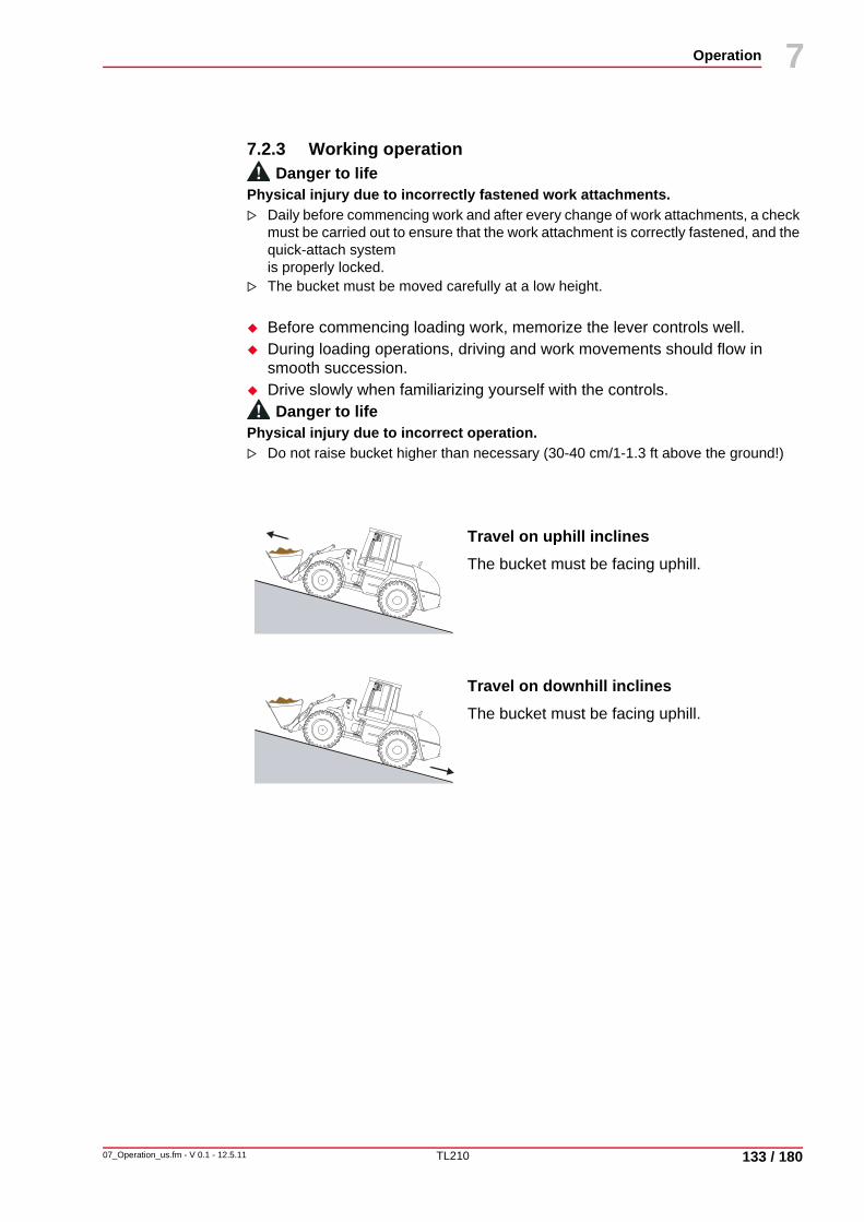
TL210
Operation
07_Operation_us.fm - V 0.1 - 12.5.11 133 / 180
7
14
7.2.3 Working operationDanger to life
Physical injury due to incorrectly fastened work attachments. Daily before commencing work and after every change of work attachments, a check must be carried out to ensure that the work attachment is correctly fastened, and the quick-attach system is properly locked.The bucket must be moved carefully at a low height.
Before commencing loading work, memorize the lever controls well.During loading operations, driving and work movements should flow in smooth succession.Drive slowly when familiarizing yourself with the controls.Danger to life
Physical injury due to incorrect operation. Do not raise bucket higher than necessary (30-40 cm/1-1.3 ft above the ground!)
Travel on uphill inclinesThe bucket must be facing uphill.
Travel on downhill inclinesThe bucket must be facing uphill.

TL210
Operation
134 / 180
7
07_Operation_us.fm - V 0.1 - 12.5.11
14
Operation of work equipment
Fig. 7-14 Operating the loader
Operating the loaderSet the multi-function switch (1) to the forward switch position.The working hydraulics will be switched on.
Operating the loading bucketOperate the loading bucket with the joystick (3).
Operation of additional control circuit (adjustable)Set the additional control circuit (4) to the center position.Press right-hand / left-hand push-button switch (2) (e.g. open/ close multi-purpose bucket). Additional control circuit only active as long as the push-button switch is pressed (pulse-mode).
Move the attachment to operating position.Operate the turning knob (5) to adjust hydraulic power (e.g. rotational speed).
NoteThe additional control circuit must always be switched off unless additional equipment is operated. The hydraulic power of a number of attachments must be adjusted, e.g. rotational speed of sweepers, etc.
UNIDECKUNIDECK
P
- +
HAZARD
P
AUTO OFF
0I
4560_7010
3
2
4
5
1
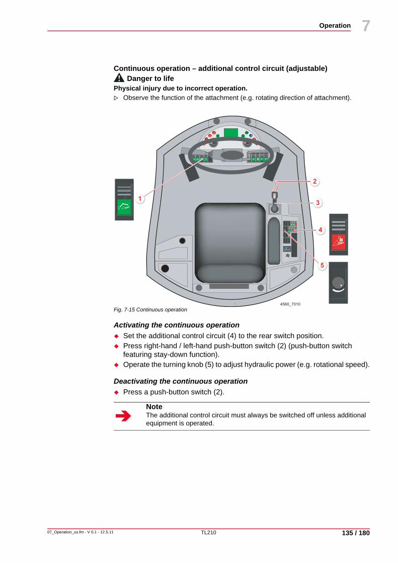
TL210
Operation
07_Operation_us.fm - V 0.1 - 12.5.11 135 / 180
7
14
Continuous operation – additional control circuit (adjustable)Danger to life
Physical injury due to incorrect operation. Observe the function of the attachment (e.g. rotating direction of attachment).
Fig. 7-15 Continuous operation
Activating the continuous operationSet the additional control circuit (4) to the rear switch position.Press right-hand / left-hand push-button switch (2) (push-button switch featuring stay-down function).Operate the turning knob (5) to adjust hydraulic power (e.g. rotational speed).
Deactivating the continuous operationPress a push-button switch (2).
NoteThe additional control circuit must always be switched off unless additional equipment is operated.
UNIDECKUNIDECK
P
- +
HAZARD
P
AUTO OFF
0I
4560_7010
3
2
4
5
1

TL210
Operation
136 / 180
7
07_Operation_us.fm - V 0.1 - 12.5.11
14
Float position of lift frame
Fig. 7-16 Float position
Adjusting the impulse modePlace the loading bucket on the floor.Push joystick forwards beyond the pressure point.The float position is activated for as long as the joystick is held in the pressed position.
Adjusting the continuous operationPlace the loading bucket on the floor.Move the switch (2) to the rear switch position.The green indicator lamp lights up.Push joystick forwards beyond the pressure point.Joystick is automatically engaged in this position.
Exiting continuous operation
Exit continuous operation by returning the joystick to neutral or moving the switch (2).
UNIDECKUNIDECK
P
-+
HAZARD
P
AUTO OFF
0I
14560_7011_a
2
NoteThe float position must always be disengaged unless operated. Move the switch (2) to position "1".

TL210
Operation
07_Operation_us.fm - V 0.1 - 12.5.11 137 / 180
7
14
7.2.4 Changing work attachmentsVarious work attachments are available to achieve maximum utilization of the machine for a variety of applications.
The machine is equipped with a quick-attach system, to shorten the time it takes to change attachments.
When mounting a multi-purpose bucket, front sweeper, etc., an additional control circuit is required.
Danger to lifePhysical injury due to incorrectly fastened work attachment.
Perform a visual check to ensure that the quick-attach system is correctly locked.
Damage to persons and propertyDanger of injury due to unsecured work attachments.
Secure unused working attachments with wedges or similar.
Property damageMachine damage due to additional control circuit which has not been switched off.
The additional control circuit must be switched off unless a hydraulically operated additional attachment is connected.
Changing directly mounted work attachments
Place the work attachment on the ground so that it cannot tip or turn over.Remove the pin of the linkage and the pin of the lift frame.Remove the lift frame from the work attachment and mount the new work attachment.
NoteUnder certain circumstances, it is possible to use the work attachments of predecessor models on our machines. When mounting work attachments of predecessor models, however, these may have to be adjusted and/or are subject to utilization restrictions. The installation of work attachments which are not included in our product range requires our written approval. It is essential to consult your dealer before mounting such a work attachment.
NoteThe bearings on the quick-attach system and work attachment must be free of dirt.
NoteBefore disconnecting hydraulic connections, the system must be released from pressure.
NoteIn the event of a hydraulically operated attachment, first of all the hydraulic connection must be disconnected (system must be without pressure).
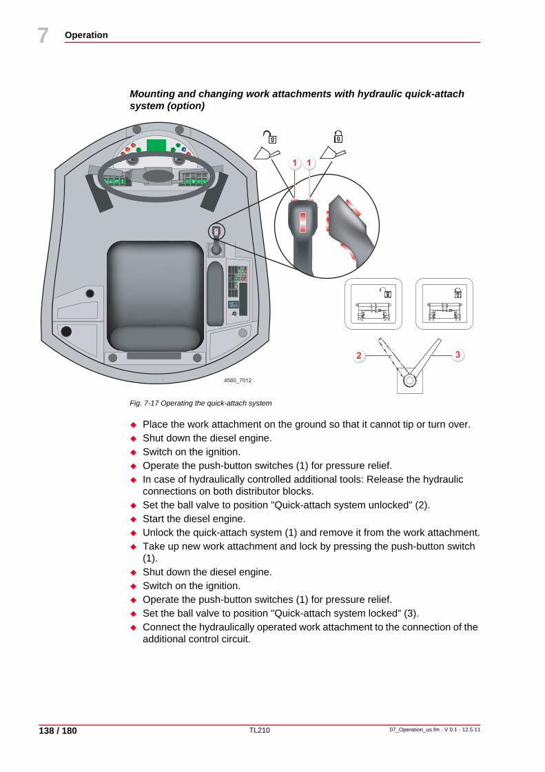
TL210
Operation
138 / 180
7
07_Operation_us.fm - V 0.1 - 12.5.11
14
Mounting and changing work attachments with hydraulic quick-attach system (option)
Fig. 7-17 Operating the quick-attach system
Place the work attachment on the ground so that it cannot tip or turn over.Shut down the diesel engine.Switch on the ignition.Operate the push-button switches (1) for pressure relief.In case of hydraulically controlled additional tools: Release the hydraulic connections on both distributor blocks.Set the ball valve to position "Quick-attach system unlocked" (2).Start the diesel engine.Unlock the quick-attach system (1) and remove it from the work attachment.Take up new work attachment and lock by pressing the push-button switch (1).Shut down the diesel engine.Switch on the ignition.Operate the push-button switches (1) for pressure relief.Set the ball valve to position "Quick-attach system locked" (3).Connect the hydraulically operated work attachment to the connection of the additional control circuit.
UNIDECKUNIDECK
P
- +
HAZARD
P
AUTO OFF
0I
4560_7012
11
32

TL210
Operation
07_Operation_us.fm - V 0.1 - 12.5.11 139 / 180
7
14
7.2.5 Loading, grading, excavatingDuring transport, the bucket - either filled or empty - must be kept as close to the ground as possible.
If possible, avoid long transport distances!
Fig. 7-18 Loading, grading
LoadingFor loading, lower the bucket and position the cutting edge parallel to the ground. Reduce driving speed by inching as required.Move the bucket into the material to be loaded.Slightly raise the lift frame as soon as the bucket is filling, and tilt back the bucket.For dumping, raise the bucket until it is above the point of dumping and dump the material.
Scraping and gradingLower the lift frame and move the cutting edge into the ground keeping a flat angle of inclination. Do not penetrate too deeply to ensure smooth removal of earth.
During this operation, the depth is only to be leveled by moving the bucket in and out.
UNIDECKUNIDECK
P
- +
HAZARD
P
AUTO OFF
0I
4560_7013
1
TL210
Operation
140 / 180
7
07_Operation_us.fm - V 0.1 - 12.5.11
14
ExcavatingTo dig out an excavation, strip layers which are as regular as possible.Plan the excavating work in such a way as to enable the wheel loader to drive forward with full bucket out of the excavation.Keep the outward run of the excavation as flat as possible.

TL210
Operation
07_Operation_us.fm - V 0.1 - 12.5.11 141 / 180
7
14
7.2.6 Ride control system (RCS) (option)Depending on the machine's operating weight, road conditions, and speed, there may be pitching oscillations when driving wheel loaders.
The ride control system reduces pitching oscillation, which results in the following advantages:
• higher transport speed• improved material-handling performance• more stable steering performance• shorter braking distance• increased ride comfort
Switching on the ride control systemSet the ride control system to the forward switch position.The green indicator lamp lights up.
The ride control system is automatically activated as soon as the travel speed is more than 6 km/h/3.7 mph.
Reducing the accumulator pressureDanger to life
Physical injury due to pressure in the hydraulic system. Before working on the loader hydraulic system, the accumulator pressure of the ride control system must be let off.
Fig. 7-19 RCS pressure reduction
NoteLoad-retaining valves (option) are without function as long as the ride control system is activated (at more than 6 km/h/3.7 mph)!
NoteThe bucket tilt cylinder must not be at a cylinder stop (bucket not completely tilted back) as otherwise free oscillation is not possible.
4560_7014
1

TL210
Operation
142 / 180
7
07_Operation_us.fm - V 0.1 - 12.5.11
14
Switch off the machine according to regulations.Set the ride control system to the rear switch position.The green indicator lamp goes out.Remove the front-end cover.Carefully release the setscrew (1).Pressure is reduced.

TL210
Operation
07_Operation_us.fm - V 0.1 - 12.5.11 143 / 180
7
14
7.2.7 Hydroinflation of tiresWhen the loader is used with a fork lift attachment, the rear wheels may be filled with a water-antifreeze mixture to increase the lifting capacity.
Prepare the mixture in an appropriately sized container. Allow it to cool and stir until there are no more lumps.
Personal injuriesDanger to health due to incorrect handling of magnesium chloride.
Observe the following items when handling magnesium chloride:Always pour magnesium chloride into the water, not the other way round! Do not allow the solution to come into contact with eyes, skin or clothing - caustic substance!
Recommendation when filled to 75% with antifreeze protection to -30° C/-22° F
Tab. 7-1 Water-antifreeze mixture
MgCl2 = Magnesium chloride
H2O = Water
Type of tire Values per wheel
MgCl2approx. kg/lbs
H2OI/gal
Totalkg/lbs
20.5 - 25 EM 16 PR SGLD 177/390 228/60 405/893
20.5 R 25 RL-2+ 245/540 300/79 545/1,202
20.5 R 25 GP-2B 245/540 300/79 545/1,202
20.5 R 25 XTLA TL 245/540 300/79 545/1,202
20.5 R 25 XHA TL 245/540 300/79 545/1,202
20.5 R 25 XLDD2A 210/463 260/69 470/1,036
20.5 R 25 X Mine D2 210/463 260/69 470/1,036

TL210
Operation
144 / 180
7
07_Operation_us.fm - V 0.1 - 12.5.11
14
7.2.8 Notes for winter operationThe following points and the relevant notes in the engine instruction manual should be observed during winter operation.
Hydraulic oil If the machine has not been used for longer periods of time at temperatures around and below freezing, warm up the engine by running at medium revs for approx. 3-5 min.
Engine oil The oil viscosity (SAE class) should be selected according to the ambient temperature at the machine's place of operation.
Condition of the battery
A good cold start performance requires a well-charged battery.
Warm up the battery to approx. +20° C/68° F (remove the battery after shutting down the engine and store it in a warm room). This can help to lower the start limit temperatures by 4° C/39.2° F-5° C/41° F.Ensure good contact of the terminal connections when installing the battery.Only tighten terminal screws “hand-tight”, to prevent deformation of the terminal cones!
Coolant Check the antifreeze setting before the beginning of the cold season.Match the antifreeze to the ambient temperature, as required. At the factory, the antifreeze protection is set to approx. -25° C/-13° F.
Fuel Only use commercially available brand-name diesel fuel with a sulfur content of less than 0.5 %.Use only winter diesel fuel in winter to prevent line connections becoming blocked through paraffin deposits. At very low temperatures, troublesome deposits may also occur when winter diesel is used.

TL210
Transportation
08_Transportation_us.fm - V 0.1 - 12.5.11 145 / 180
8
15
8 Transportation
8.1 Recovering the wheel loaderDanger to life
Physical injury due to rolling away of machine. Always secure the machine with chocks and relieve the hydraulic system of pressure before carrying out maintenance and repair work.
Property damageMachine damage due to excessively fast towing.
Tow the machine at walking speed.Tow the machine to a maximum distance of 50 m/164 ft.
Property damageMachine damage due to hydraulic system contamination.
Absolute cleanliness is essential when working on the hydraulic system.
NoteStrictly observe all safety notes.See chapter 3.20 "Recovery, loading and transporting", page 29.
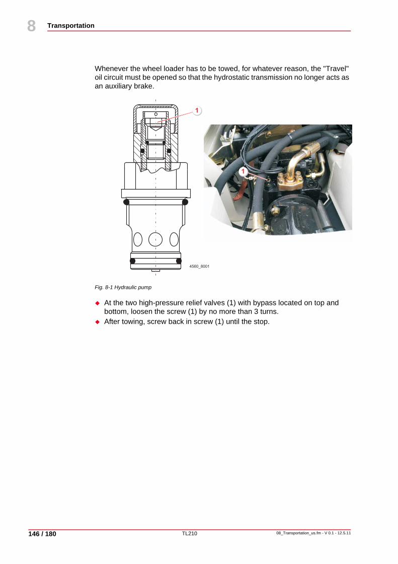
TL210
Transportation
146 / 180
8
08_Transportation_us.fm - V 0.1 - 12.5.11
15
Whenever the wheel loader has to be towed, for whatever reason, the "Travel" oil circuit must be opened so that the hydrostatic transmission no longer acts as an auxiliary brake.
Fig. 8-1 Hydraulic pump
At the two high-pressure relief valves (1) with bypass located on top and bottom, loosen the screw (1) by no more than 3 turns.After towing, screw back in screw (1) until the stop.
4560_8001
1
1

TL210
Transportation
08_Transportation_us.fm - V 0.1 - 12.5.11 147 / 180
8
15
Recovering the wheel loader
Towing of the wheel loader must be restricted to clearing a junction or a road, to prevent damage to the hydrostatic travel drive.
If possible, let the diesel engine run at low idle during towing.
Towing lugs For towing the wheel loader the following towing lugs are available:
Fig. 8-2 Towing lugs
1 right and left on the axle plates2 bottom right and left on the side plates of the rear end
NoteMax. load suspension of towing lugs approx. 14,500 kg/31,973 lbs.
4560_8004
2
2
1
1

TL210
Transportation
148 / 180
8
08_Transportation_us.fm - V 0.1 - 12.5.11
15
Releasing the spring-loaded brake
Fig. 8-3 Releasing the spring-loaded brake
Switch on the ignition (2).Release the spring-loaded brake by operating the switch (1).If the spring-loaded brake cannot be released, release it in both axles by screwing in the adjusting screws (3) by 30 mm/1 ft (4).
UNIDECKUNIDECK
P
- +
HAZARD
P
AUTO OFF
0I
4560_8002
1
2
3
4
P
NoteAfter towing, re-adjust the spring-loaded brake.

TL210
Transportation
08_Transportation_us.fm - V 0.1 - 12.5.11 149 / 180
8
15
8.2 Lifting with a craneDanger to life
Danger to life when exceeding the maximum weight-lifting capacity.Ensure that the maximum lifting capacity of the crane and the crane harness is not exceeded.
Fig. 8-4 Lifting positions
Lifting the wheel loaderEmpty the bucket and tip back.Move the lift frame to travel position.Apply the pin of the articulation lock (2) on the articulation.Shut down the engine.Leave the machine and close the door.Attach the loader to the hoisting appliance at the specified, marked points (1) in the correct manner.
4560_8003
1
1
1
1 2

TL210
Transportation
150 / 180
8
08_Transportation_us.fm - V 0.1 - 12.5.11
15
8.3 TransportDanger to life
Danger to life due to disregarding the total transport height.It is essential to observe the clearance heights of tunnels, bridges, etc.
To transport the machine onto a flat bed trailer, railway goods wagon, etc. the following measures must be taken:
Securing the wheel loaderEmpty the bucket and tilt it in.Drive the machine onto the flat bed trailer, goods wagon, etc., or lift by crane if required.Apply the pin of the articulation lock (2) on the articulation.Place the working attachment on the floor.Shut down the engine.Leave the machine and close the door.Lash the machine to the hoisting appliance at the specified, marked points (1) in the correct manner.
Fig. 8-5 Lashing points
4560_8005
2
1
1
1
1
1
1

Specifications 9
9 Specifications
9.1 Views
9.1.1 Dimensioned drawing with bucket, directly mounted
Fig. 9-1 Dimensioned drawing with bucket and tires 20.5 R 25
4560_9001_us
3100/122 1684/66
35°
62
0/2
4
40
40
/15
9
40°
80
°
R3060/121
1900/75
2500/98
23
50
/93
70
/2.8
116°
1100/4345°
29
20
/11
5
51°
7230/285
R6150/242
32
60
/12
8
TL21009_Specifications_us.fm - V 0.1 - 12.5.11 151 / 18016

Specifications9
9.1.2 Dimensioned drawing with bucket and quick-attach system
Fig. 9-2 Dimensioned drawing with loading bucket and quick-attach system and tires 20.5 R 25
4560_9002_us
3100/122 1684/66
35°
62
0/2
4
40
40
/15
9
40°
80
°
R3060/121
1900/75
2500/98
23
50
/93
117°
1180/46
28
40
/11
2
51°
10
0/4
45°
7320/288
R6200/244
32
60
/12
8
TL210152 / 180 09_Specifications_us.fm - V 0.1 - 12.5.11
16

Specifications 9
9.2 Technical data
9.2.1 Engine
Tab. 9-1 Engine
EngineManufacturer Cummins
Type Diesel
Design 6 cylinders in lineFour-stroke diesel engine with turbocharger and charge-air cooler, ex-haust-gas optimized (EPA III, EC Stage III)
Displacement 6700 cm3/409 in3
Power output according to DIN 70020 119 kW/160 HP at 2200 rpm
Torque 732 Nm/540 lbf ft / 1400 rpm
Specific fuel consumption at nominal engine speed 219 g/kWh/0.13 lb/hph
Cooling Water-antifreeze mixture for all-year operation
Heating Cab hot water heating with three-speed heater fan
Max. inclined position 30° in all directions
Engine lubricating-oil supply Observe the overturning limit angle of the machine!
TL21009_Specifications_us.fm - V 0.1 - 12.5.11 153 / 18016

Specifications9
9.2.2 Electrical system
Tab. 9-2 Electrical system
9.2.3 Travel drive• Two-stage hydrostatic travel system with variable displacement axial piston
motor and reduction gear
Automatic changeover between low and high speed range
Tab. 9-3 Travel drive
Electrical systemNominal voltage 24 V
Battery 2 x 12 V – 110Ah / 850A (EN) / 510 A (DIN)
Generator 24 V – 70A
Starter 24 V / 4.5 kW/6 HP
Cold-starting aid 1 glow element per cylinder
Lighting system in compliance with Ger-man Road Traffic Regu-lations (StVZO) with Halogen H 4 headlamps, 2 front and 2 rear work-ing floodlights
Travel driveTravel drive Variable displacement pump,
flange-mounted directly onto diesel engine, two-stage variable displace-ment motor with power shift on rear axle reduction gear.
Suction and return filter in the form of a tank insert filter.
Travel speed Forward - Reverse
Travel range "Work" 0 - 6.0 km/h/0 - 3.7 mph
Travel range "Road" 0 - 40 km/h/0 - 25 mph
Power transmission Hydrostatic travel drive with ad-vanced driving automatics. Auto-matic adjustment of propulsive force and speed. Continuous speed regu-lation forward and in reverse. Four-wheel drive via propeller shaft con-nection.
Max. operating pressure - driving
max. 420 bar/6,090 psi
TL210154 / 180 09_Specifications_us.fm - V 0.1 - 12.5.11
16

Specifications 9
9.2.4 Brakes
Tab. 9-4 Brakes
BrakesService brake Hydraulic two-circuit power brake. Wet discs in both axles
acting on all 4 wheels via four-wheel drive.
Parking brake Spring-loaded brake acting on the discs of the rear axle.
Additional brake Hydrostatic through closed-circuit travel drive.
TL21009_Specifications_us.fm - V 0.1 - 12.5.11 155 / 18016

Specifications9
9.2.5 HydraulicsHydraulic systemHydraulic pump Variable displacement piston pump with pressure-flow rate
governorPump capacity: max. 160 l/min/42 gal/min. Working pressure, steering: 175 bar/2,537.5 psiWorking pressure, loading: 270 bar/3,915.0 psi
Priority valve Priority supply of hydraulic oil to steering through load-sensing system, ensuring that all the available oil can be provided if necessary. Rapid steering movements even at low engine revs.
Steering Fully hydraulic, proportionally acting articulated steering. Two double-acting steering cylinders.
Total steering angle
80°
Loader frame Double-acting work cylinders, two lift cylinders and one tilt cylinder.Control block with load-sensing flow distribution.Control circuits "Lift / Lower" and "Dump / Tilt-back" pilot-operated.Electro-hydraulically operated float position.Single, four-way control lever (joystick) with integrated direction-of-travel switch, float position switch and switch for additional control circuit.
Additional control circuit
Max. oil flow 160 l/min/42 gal/min. Max. operating pressure 230 bar/3,335.0 psi
Hydraulic oil cooler Thermostatically controlled, hydrostatic fan drive
TL210156 / 180 09_Specifications_us.fm - V 0.1 - 12.5.11
16
Specifications 9
9.2.6 Permissible loads in compliance with German Road Traffic Regulations (StVZO)
Tab. 9-5 Permissible loads in compliance with German Road Traffic Regulations (StVZO)
9.2.7 Sound level values, vibration
Tab. 9-6 Sound level values
Tab. 9-7 Vibration values
Permissible loads in compliance with German Road Traffic Regulations (StVZO)Permitted overall weight see type label, or
General CertificationPermissible axle load, front
Permissible axle load, rear
Sound level values in compliance with directive 2000/14/EC and EN 474Guaranteed sound power level LWA = 105 dB (A)
Sound pressure level (at driver's ear) LPA = 79 dB (A)
Vibration values in compliance with directive 2002/44/EC and EN 474Effective values of acceleration below 0.5 m/s²/20 in/s² for entire body
and 2.5 m/s²/98 in/s² for upper limbs.
TL21009_Specifications_us.fm - V 0.1 - 12.5.11 157 / 18016

Specifications9
9.3 Dimensions and weights
Specifications refer to general-purpose bucket and 20,5 R 25 tires
Tab. 9-8 Dimensions and weights
Specifications refer to general-purpose bucket and 20.5 R 25 tires Stability conforms to DIN 24094
Dimensions and weightsOperating weight, standard equipment1) approx. 12,500 kg/
27,563 lbs
Total length, standard bucket on ground (quick-attach system / directly mounted)
7,095/7,085 mm/279.4/ 279.0 in
Total width 2,500 mm/98.5 in
Total height (cab roof) 3,260 mm/128.4 in
Wheel base 3,100 mm/122.1 in
Track width FR / RR 1,900 mm/74.8 in
Rear overhang angle 35°
Ground clearance below propeller shaft 620 mm/24.4 in
Turning radius at outside edge of bucket in transport position (quick-attach system/ directly mounted)
6,020/5,970 mm/237.1/235.1 in
Turning radius at inside edge of tires 3,060 mm/ 120.5 in1) according to ISO 6016
Front loader installation Quick-attach system
Direct mounting
Width of bucket 2,500 mm/98.5 in 2,500 mm/98.5 in
Capacity to DIN/ISO 7546 (max. density = 1.8 t/m³/112lb/ft³)
approx. 2.0 m1/6.6 ft1) approx.2.1 m1/6.9 ft1)
Payload in bucket 3,600 kg/7,938 lbs 3,780 kg/8,335 lbs
Dump height at 45° dump angle 2,980 mm/117.4 in 3,010 mm/118.5 in
Dump reach at max. dump height 1,020 mm/40.2 in 970 mm/38.2 in
Max. bucket hinge pin height 4,040 mm/159.1 in 4,040 mm/159.1 in
Reset angle 50° 50°
Dump angle at max. dump height 45° 45°
Digging depth, horizontal bucket 100 mm/3.9 in 70 mm/2.8 in
Lift capacity at ground level according to ISO 8313
123.4 kN/27,740.3 lbf 123.4 kN/27,740.3 lbf
Ripping force at cutting edge of bucket1
104.5 kN/23,491.6 lbf 104.5 kN/23,491.6 lbf
Tipping load, straight 8,340 kg/18,390 lbs 8,700 kg/19,184 lbs
TL210158 / 180 09_Specifications_us.fm - V 0.1 - 12.5.11
16

Specifications 9
Tab. 9-9 Dimensions and weights
Tab. 9-10 Bucket dimensions
Fork-arm connection in compliance with ISO/FEM Class 3 Form B, DIN 15 173 / ISO 2328 respectively
Tab. 9-11 Dimensions of fork lift attachment
The payloads are determined in compliance with DIN 24094 / ISO 8313 respectively with a stability factor of 1.25 or 80 % of the tipping load and the
Tipping load, articulated 7,280 kg/16,052 lbs 7,600 kg/16,758 lbs
Work cycle time, "Lift" 5.9 s 5.9 s
Work cycle time “Lower” 3.9 s 3.9 s
Work cycle time “Dumping in uppermost position – IN”
1.7 s 1.7 s
Work cycle time “Dumping in upper position – OUT”
1.2 s 1.2 s
1)according to ISO 8313
Bucket Widthmm/in
Capacity, heaped 1)
m3/in3
Max. density (γ)t/m3/lb/ft3
Bucket 2,500/98.5 2.0 / 2.1/122/128
1.8/112
Bucket with bolt-on cutting edge
2,500/98.5 2.0 / 2.1/122/128
1.8/112
Earth bucket 2,500/98.5 2.2 / -/134/ -
1.6/100
Earth bucket with bolt-on cutting edge
2,500/98.5 2.2 / -/134/ -
1.6/100
Light-material bucket 2,500/280098.5/110.3
2.8 / 3.5/171/214
1.2/75 / 0.8/50
Multi-purpose with teeth
2,500/98.5 1.8 / -110/ -
1.6/100
1)Quick-attach system / directly mounted
Fork lift attachment mm/inWidth of fork carrier 1,900/74.8
Length of forks 1,200/47.3
Fork cross section 150 x 60/ 5.9 x 2.4
Max. stacking height 3830/150.8
Front loader installation Quick-attach system
Direct mounting
TL21009_Specifications_us.fm - V 0.1 - 12.5.11 159 / 18016

Specifications9
machine moving over level ground.
The payloads are valid for the machine fitted with 20.5 R25 tires and the equipment condition as described in compliance with ISO 6016.
Tab. 9-12 Total lift range of fork attachment
Tab. 9-13 Transport position of fork lift attachment
If screw-on rear axle weights or rear tires with hydroinflation are used.
Total lift range
S=2.0 S=1.25
kg 2800 4500
lbs 6170 9900
kg 3125 5000
lbs 6890 11,000
Transport position
S=1.67 S=1.25
kg 3740 5000
lbs 8228 11000
kg 3740 5000
lbs 8228 11000
NoteDuring fork lift operations, the tire pressure of the front wheels must be increased by at least 0.5 bar/7.3 psi.
500 mm19,7 inch
+0,5 bar+7,3 psi + kg
lbs
4560_9001
kglbs
kglbs
500 mm19,7 inch
+0,5 bar+7,3 psi + kg
lbs
4560_9002
kglbs
kglbs
kglbs
TL210160 / 180 09_Specifications_us.fm - V 0.1 - 12.5.11
16

Specifications 9
9.3.1 Cab• Spacious, sound-insulated full-vision steel cab, FOPS (acc. to ISO 3449) and
ROPS (acc. to ISO 12117) certified• Door with large access on left hand side• Sliding window on left-hand side• Safety glass• Thermal windows tinted green• Rear panorama window• Windscreen washing system• Storage rack• Preparation for radio installation• Outside rear-view mirrors on both sides
Heating/ventilation
• Automatic climate control
Driver's seat • Comfort seat with fabric lining, weight, longitudinal and inclination adjustment• Lap seat belt• Armrest right
Operating controls
• Control console to the right of the driver's seat• Visual and audible warning systems• Operating-hour meter• Instrument cluster with large tank display• Working flood lights Halogen H-3 FR / RR
Options • Rotating beacon• Radio• Immobilizer• Vandalism guard only for canopy version• 2. Additional control circuit
TL21009_Specifications_us.fm - V 0.1 - 12.5.11 161 / 18016
Specifications9
9.3.2 Pressure chart
NoteThe tire pressures refer to standard equipment.
NoteDuring fork lift operations, the tire pressure of the front wheels must be increased by at least 0.5 bar/7.3 psi.
Air pressureTire size Front wheels
[bar/psi]Rear tires[bar/psi]
20.5 R25 EM 3.0/43 1.7/25
20.5-25 EM 2.5/36 2.2/32
20.5 R25 XHA 2,0/29 2.0/29
TL210162 / 180 09_Specifications_us.fm - V 0.1 - 12.5.11
16

Specifications 9
9.3.3 Optional accessoriesProperty damage
Machine damagecaused by unauthorized alterations to the design, additional equipment and work attachments of Terex products.
Alterations must be approved by the manufacturer in writing. If our approval is not sought, our warranty expires, as does our product liability for any resulting consequential damage.
• Orthopedic air-cushioned driver's seat• Fire extinguisher• Pressurized cab• Independent diesel heating with timer• Diverse electrical accessories such as working floodlights, rotating beacon,
radio, etc.• Sliding window, door• Diesel exhaust cleaner• Catalyst• Ride control system• Anti-theft device• Back-up alarm system• Electrical tank refilling pump• Quick-attach system, hydraulically operated• Snow blade• Sweeper• Load hook for attaching to forks• Rear axle weights• Filling with biodegradable hydraulic oil (ester-based "BIO-E-HYD-HEES")
NoteAdditional accessories available from the manufacturer.
TL21009_Specifications_us.fm - V 0.1 - 12.5.11 163 / 18016

Specifications9
TL210164 / 180 09_Specifications_us.fm - V 0.1 - 12.5.11
16

TL210
Troubleshooting
10_Troubleshooting_us.fm - V 0.1 - 12.5.11 165 / 180
10
17
10 Troubleshooting
Malfunctions are frequently caused by:
• incorrect handling of the machine.• use of unsuitable fuels and lubricants.• irregular maintenance.
10.1 Who is allowed to rectify malfunctions?• During the warranty period, malfunctions must be dealt with by your
responsible Service Agent or a specialist workshop.• If a problem can only be eliminated through repair, then your responsible
Service Agent must be called in.
Engine faults • All defects and faults in the diesel engine must be examined as described in the separate engine instruction book.
• During the warranty period, malfunctions must be dealt with by the responsible SERVICE Agent or a specialist workshop.
10.2 Before trouble shooting and fault rectificationPark the wheel loader on a solid and level base. The wheel loader is only to be parked in places where it does not obstruct e. g. the public or the construction site traffic. Place the working attachment on the floor. Shut down the engine and pull out the ignition key.Close or lock windows and doors.Secure the wheel loader with wheel chocks against rolling.

TL210
Troubleshooting
166 / 180
10
10_Troubleshooting_us.fm - V 0.1 - 12.5.11
17
10.3 Trouble shooting and fault rectification
Malfunction No steering movement
Cause • Oil supply to pump interrupted• Hydraulic pump damaged• Priority valve damaged• Hand metering unit damaged• Steering cylinder damaged• Mechanical fault
Remedy Only Terex-customer service personnel are permitted to undertake the following type of work.
Check and repair suction lineRepair or replace the hydraulic pumpRemedy damage to priority valveRemedy damage to hand metering unitRepair steering cylinderRemedy mechanical fault
Malfunction Insufficient performance of service brake
Cause • Wear in brake discs• Brake control system damaged• Mechanical fault
Remedy Adjust or repair brake discs (call Service Agent)Repair or replace brake control system (call Service Agent)Remedy mechanical fault (call Service Agent)
Malfunction Insufficient performance of parking brake
Cause • Wear in brake discs• Hydraulic fault in brake actuation
Remedy Only Terex-customer service personnel are permitted to undertake the following type of work.
Re-adjust or repair brake discsReplace and/or re-adjust brake actuation
TL210
Troubleshooting
10_Troubleshooting_us.fm - V 0.1 - 12.5.11 167 / 180
10
17
Malfunction Hydrostatic travel drive without neutral position
Cause • Switch for travel direction damaged• Solenoids of valve damaged• Neutral position incorrectly adjusted• Internal damage to travel pump • Excessive engine idling
Remedy Only Terex-customer service personnel are permitted to undertake the following type of work.
Replace or repair direction switchCheck / re-calibrate solenoids of valve (call Service Agent)Replace travel pumpRe-adjust engine idling
Malfunction Hydraulic oil exceeds max. admissible temperature
Cause • Thermo switch damaged• Oil level too low• Oil cooler dirty or damaged• Suction filter clogged• High-pressure valves do not respond all the time or too early• Flushing circulation not functioning• Travel pump or travel motor damaged (wear)• Loader pump worn• Main pressure relief valve damaged
Remedy Replace suction filterTop up oil to mark on dipstickClean, check and, if necessary, replace oil cooler
Only Terex-customer service personnel are permitted to undertake the following type of work.
Replace thermo switchCheck high-pressure valves, re-adjust or replace if necessaryCheck pressure of flushing and charge pump, possible back pressure in cooling circuit, check housing pressureReplace travel pump or travel motorReplace working pumpReplace main pressure relief valve

TL210
Troubleshooting
168 / 180
10
10_Troubleshooting_us.fm - V 0.1 - 12.5.11
17
Malfunction Sluggish acceleration and deceleration, too little propulsive power
Cause • Insufficient engine power• Brake has got stuck• No tank pressurization• Suction filter clogged• FAST-SLOW-gear not functioning due to electric or mechanical fault• Fault in operation of brake-inching pedal• Charge pump sucking up air• Travel pump incorrectly adjusted• Insufficient charge or supply pressure• Pressure relief valve of charge circuit dirty or damaged• Insufficient high-pressure• Travel pump does not open fully, pilot pressure too low• Internal damage to travel pump or travel motor• Travel motor mis-adjusted
Remedy Check ventilation filters and breathers, replaceReplace suction filter
Only Terex-customer service personnel are permitted to undertake the following type of work.
Check diesel engineCheck and repair brakeCheck power supply and solenoid valve, repair and replace if necessaryCheck, adjust, replace brake-inching deviceCheck charge pump, eliminate leaksRe-adjust travel pumpCheck and adjust charge or supply pressureCheck, re-adjust or replace pressure relief valve of charge circuitCheck high-pressure; re-adjust or replace pressure cut-off and high-pressure valves if required.Nozzles clogged, check, repairReplace travel pump or travel motorRe-adjust travel motor

TL210
Troubleshooting
10_Troubleshooting_us.fm - V 0.1 - 12.5.11 169 / 180
10
17
Malfunction Transmission works in one direction only
Cause • Switch for travel direction damaged• Solenoid valve gets stuck or is damaged• Power supply towards switch for travel direction or solenoid valve interrupted• Pilot pressure too low on one side• High-pressure relief valve is faulty or incorrectly adjusted
Remedy Only Terex-customer service personnel are permitted to undertake the following type of work.
Repair or, if necessary, replace direction switchRepair or, if necessary, replace solenoidCheck and repair power supply towards switch for travel direction (incl. ground connection)Nozzles clogged, check, repairSwap valves around. If machine now travels in the other direction, examine valve, clean and replace if necessary
Malfunction Transmission works in neither direction
Cause • Too little hydraulic oil in tank• Mechanical connection to diesel engine faulty• Charge pump damaged, no charge pressure• Switch for travel direction damaged• Solenoid valve for travel direction damaged• Suction filter clogged• Suction line between tank and pump kinked• Power supply towards switch for travel direction and solenoid valve interrupted• Internal damage to travel pump or travel motor• Mechanical connection between travel motor and axle interrupted
Remedy Only Terex-customer service personnel are permitted to undertake the following type of work.
Top up hydraulic oil to mark on dipstickCheck and repair mechanical connection to diesel engineRemove charge pump and examine, install new pump if necessaryRepair or, if necessary, replace direction switchRepair or, if necessary, replace solenoid valve for travel directionReplace suction filterCheck and eliminate kink in suction line between tank and pumpRemedy interruption of power supply towards switch for travel directionReplace travel pump or travel motor completelyCheck and repair mechanical connection between travel motor and axle

TL210
Troubleshooting
170 / 180
10
10_Troubleshooting_us.fm - V 0.1 - 12.5.11
17
Malfunction Loader installation is not working
Cause • Oil supply to pump interrupted• Main pressure relief valve damaged• Hydraulic pump damaged• Hydraulic pump drive mechanically interrupted
Remedy Check suction line
Only Terex-customer service personnel are permitted to undertake the following type of work.
Check and replace main pressure relief valve if necessaryCheck, repair or replace the hydraulic pumpCheck and repair hydraulic pump drive
Malfunction Decrease in machine's performance (loader installation)
Cause • Insufficient engine power• Hydraulic oil level too low• Pump is sucking up air• Insufficient operating pressure• Pump worn• Incorrect hydraulic oil
Remedy Check diesel engineTop up hydraulic oil to mark on dipstickQuality of hydraulic oil must conform to our recommendation
Only Terex-customer service personnel are permitted to undertake the following type of work.
Re-tighten hose connections. Replace O-ring or sealsRe-adjust main pressure relief valve, replace if necessaryReplace pump
Malfunction Working cylinders are not working satisfactorily
Cause • Seals in cylinders worn• Secondary valves defective
Remedy Only Terex-customer service personnel are permitted to undertake the following type of work.
Re-seal cylindersCheck secondary valves and replace completely if necessary
TL210
Troubleshooting
10_Troubleshooting_us.fm - V 0.1 - 12.5.11 171 / 180
10
17
Malfunction Faults in the electrical system
Cause • Outside and/or internal lighting damaged• Windshield wiper not working• Horn not responding• Control organs are imprecise• Starting system does not work satisfactorily
Remedy Check cables, connections, bulbs and fuses of outside and/or internal lightingCheck cables, connections, and fuses of windshield wipersExamine windshield wiper for mechanical damage, replace if necessaryCheck cables, connections, and fuses of hornReplace complete horn if requiredDetermine the fault or source of the control organ problems, call Service Agent if necessaryCheck charge capacity of batteryTest starter functionCheck connection and condition of power and battery ground cablesCheck function of ignition lock, replace if necessary

TL210
Troubleshooting
172 / 180
10
10_Troubleshooting_us.fm - V 0.1 - 12.5.11
17
10.3.1 Immobilizer faults
Malfunction Immobilizer has no function
Remedy Inspect voltage supply on plug contacts.Check antenna plug-in connection.Check antenna cable.Use key with learned transponder.
Malfunction Key learning not possible
Remedy Terminal 30 not connected to control unit.No or incorrect master key used previously (red grip).Time for master key in ignition too short or too long.Key to be learned does not have transponder.Defective antenna.Learning time for key in ignition too short.
Malfunction Clearing of learned keys not possible
Remedy No or incorrect master key used (red grip).Time for master key in ignition lock too short.Defective antenna.

TL210
Service and spare parts information
11_Service_us.fm - V 0.1 - 12.5.11 173 / 180
11
17

TL210
Service and spare parts information
174 / 180
11
11_Service_us.fm - V 0.1 - 12.5.11
17

TL210
Index
Index_enSIX.fm - V 0.1 - 12.5.11 175 / 180
12
18
12 Index
AAccumulator pressure . . . . . . . . . . . . . . . . 141Additional control circuit . . . . . . . . . . . 37, 134Adjusting heating, ventilation and air-conditioning 112Adjusting the driver's seat . . . . . . . . . . . . . 110Adjusting the fan speed . . . . . . . . . . . . . . 113Adjusting the lighting in compliance with German Road Traffic Regulations (StV-ZO) . . . . . . . . . . . . . . . . . . . . . . . . . . . . . . 114Adjusting the travel direction . . . . . . . . . . . 123Air filter . . . . . . . . . . . . . . . . . . . . . . . . . . . . 14Air filter control . . . . . . . . . . . . . . . . . . . . . . 36Air filter main cartridge . . . . . . . . . . . . . . . . 76Air filter safety cartridge . . . . . . . . . . . . . . . 76Air intake system . . . . . . . . . . . . . . . . . . . . 75Air pressure . . . . . . . . . . . . . . . . . . . . . . . . 99
BBattery . . . . . . . . . . . . . . . . . . . . . . . . . . . 100Battery charge indicator . . . . . . . . . . . . . . . 14Brake accumulator pressure . . . . . . . . . 14, 36Brake-inching mechanism . . . . . . . . . . . . 129Brakes . . . . . . . . . . . . . . . . . . . . . . . . 128, 155Bucket return positioner . . . . . . . . . . . . 15, 36
CCab . . . . . . . . . . . . . . . . . . . . . . . . . . . . . . 161Cab ventilation dust filter . . . . . . . . . . . . . 103Canopy . . . . . . . . . . . . . . . . . . . . . . . . . . . . 23Carbon filter contamination . . . . . . . . . . . . . 15Cartridge maintenance intervals . . . . . . . . . 76Caution . . . . . . . . . . . . . . . . . . . . . . . . . . . . 11Changeover fan/engine cooling . . . . . . . . . 15Changing coolant . . . . . . . . . . . . . . . . . . . . 71Changing the engine oil . . . . . . . . . . . . . . . 67Changing the engine oil filter . . . . . . . . . . . 68Changing the filter insert . . . . . . . . . . . . 89, 91Changing the hydraulic oil . . . . . . . . . . . . . 87Changing the main cartridge . . . . . . . . . . . . 77Changing the V-belt . . . . . . . . . . . . . . . . . . 85Changing work attachments . . . . . . . . . . . 137Charge control lamp . . . . . . . . . . . . . . . . . . 36Checking antifreeze . . . . . . . . . . . . . . . . . . 70Checking the air intake . . . . . . . . . . . . . . . . 75Checking the battery . . . . . . . . . . . . . . . . . 100Checking the coolant level . . . . . . . . . . . . . 69

TL210
Index
176 / 180
12
Index_enSIX.fm - V 0.1 - 12.5.11
18
Checking the engine oil level . . . . . . . . . . . 66Checking the hydraulic oil level . . . . . . 86, 89Checking the lighting and warning equipment 102Checking the V-belt . . . . . . . . . . . . . . . . . . 84Checking V-belt tension . . . . . . . . . . . . . . . 84Circulating air . . . . . . . . . . . . . . . . . . . 15, 112Cleaning cooling fins . . . . . . . . . . . . . . . . . 72Cleaning the dust ejection valve . . . . . . . . 75Cleaning the dust filter for cab ventilation 103Cleaning the water separator . . . . . . . . . . . 84Coming to a halt . . . . . . . . . . . . . . . . . . . . 125Condition of the battery . . . . . . . . . . . . . . 144Consumables . . . . . . . . . . . . . . . . . . . . 50, 52Continuous operation - Additional control circuit 135Conversions . . . . . . . . . . . . . . . . . . . . . . . . 27Coolant . . . . . . . . . . . . . . . . . . . . . . . . . . . 144Coolant level . . . . . . . . . . . . . . . . . . . . . . . 15Coolant temperature . . . . . . . . . . . . . . 14, 36Cooling . . . . . . . . . . . . . . . . . . . . . . . . 15, 112Copyright . . . . . . . . . . . . . . . . . . . . . . . . . . . 5Customer service . . . . . . . . . . . . . . . . . . . 173
DDaily tasks . . . . . . . . . . . . . . . . . . . . . . . . . 59Danger . . . . . . . . . . . . . . . . . . . . . . . . . . . . 11Danger zone . . . . . . . . . . . . . . . . . . . . . . . . 20Declaration of Conformity . . . . . . . . . . . . . . . 8Deployment location . . . . . . . . . . . . . . . . . . . 5Differential of rear axle with transmission . 97Dimensions and weights . . . . . . . . . . . . . 158Direction indicator . . . . . . . . . . . . . . . . 14, 36Display . . . . . . . . . . . . . . . . . . . . . 36, 39, 112Display elements and operating controls . . 35Displaying interior/exterior temperature . . 113Draining the fuel filter . . . . . . . . . . . . . . . . . 81Draining water from the fuel tank . . . . . . . . 83Driver's seat . . . . . . . . . . . . . . . . . . . . . . . 161Driving . . . . . . . . . . . . . . . . . . . . 22, 122, 123Driving off . . . . . . . . . . . . . . . . . . . . . . . . . 124Driving on public roads . . . . . . . . . . . . . . . 131Driving on roads . . . . . . . . . . . . . . . . . . . . 130
EEconomical operation . . . . . . . . . . . . . . . . . . 5Electrical equipment . . . . . . . . . . . . . . . . . 100Electrical system . . . . . . . . . . . . . . . . . . . 154Emergency exit . . . . . . . . . . . . . . . . . . . . . 30Emergency steering . . . . . . . . . . . . . . . . . . 15Engine . . . . . . . . . . . . . . . . . . . . . . . . . . . 153

TL210
Index
Index_enSIX.fm - V 0.1 - 12.5.11 177 / 180
12
18
Engine cooler fan changeover switch . . . . . 36Engine faults . . . . . . . . . . . . . . . . . . . . . . . 165Engine oil . . . . . . . . . . . . . . . . . . . . . . 53, 144Engine oil pressure . . . . . . . . . . . . . . . . 14, 36Environmental protection . . . . . . . . . . . . . . 19Excavating . . . . . . . . . . . . . . . . . . . . 139, 140
FFalling objects . . . . . . . . . . . . . . . . . . . . . . . 23Fan . . . . . . . . . . . . . . . . . . . . . . . . . . . . . . 112Fan levels . . . . . . . . . . . . . . . . . . . . . . . . . . 15Fire extinguisher . . . . . . . . . . . . . . . . . . 16, 30Fire prevention . . . . . . . . . . . . . . . . . . . . . . 30First-aid kit . . . . . . . . . . . . . . . . . . . . . . . . . 16Float position . . . . . . . . . . . . . . . . . . . . . . . 15Fluid capacities . . . . . . . . . . . . . . . . . . . . . . 54Front control console . . . . . . . . . . . . . . . . . 36Fuel . . . . . . . . . . . . . . . . . . . . . . . . . . . 14, 144Fuel specification . . . . . . . . . . . . . . . . . . . . 51Fuel system . . . . . . . . . . . . . . . . . . . . . . . . 80Fuel-level indicator . . . . . . . . . . . . . . . . . . . 36Fuse and relay box . . . . . . . . . . . . . . . . . . . 40
GGeneral safety notes . . . . . . . . . . . . . . . . . . 19Grading . . . . . . . . . . . . . . . . . . . . . . . . . . . 139Grease gun . . . . . . . . . . . . . . . . . . . . . . . . . 15Guides . . . . . . . . . . . . . . . . . . . . . . . . . . . . 23
HHazard Classification . . . . . . . . . . . . . . . . . 11Hazard warning system . . . . . . . . . . . . . . . 15Hearing protection . . . . . . . . . . . . . . . . . . . 17Heating . . . . . . . . . . . . . . . . . . . . . . . . . . . 161High beam light . . . . . . . . . . . . . . . . . . . . . . 36High gear . . . . . . . . . . . . . . . . . . . . . . . . . . 14High-beam indicator . . . . . . . . . . . . . . . . . . 14High-gear changeover switch . . . . . . . . . . . 36Horn . . . . . . . . . . . . . . . . . . . . . . . . . . . 15, 35Hub . . . . . . . . . . . . . . . . . . . . . . . . . . . . . . . 98Hydraulic oil . . . . . . . . . . . . . . . . . 15, 53, 144Hydraulic oil level . . . . . . . . . . . . . . . . . . . . 15Hydraulic oil return filter . . . . . . . . . . . . . . . 91Hydraulic oil suction filter . . . . . . . . . . . . . . 89Hydraulic oil tank . . . . . . . . . . . . . . . . . . . . 86Hydraulic system . . . . . . . . . . . . . . . . . . . . 30Hydraulics . . . . . . . . . . . . . . . . . . . . . 156, 157Hydroinflation . . . . . . . . . . . . . . . . . . . . . . 143

TL210
Index
178 / 180
12
Index_enSIX.fm - V 0.1 - 12.5.11
18
IInitial familiarization . . . . . . . . . . . . . . . . . . 31Inspection intervals . . . . . . . . . . . . . . . . . . 46Inspection plan machine . . . . . . . . . . . . . . 61Installing batteries . . . . . . . . . . . . . . . . . . 102Installing the dust filter for cab ventilation 104Intended use . . . . . . . . . . . . . . . . . . . . . . . . 7Intermediate lubrication . . . . . . . . . . . . . . . 16
LLashing points . . . . . . . . . . . . . . . . . . . . . . 16Lateral control console . . . . . . . . . . . . . . . . 37Lifting with a crane . . . . . . . . . . . . . . . . . . 149Lighting . . . . . . . . . . . . . . . . . . . . . . . . . . . . 35Loading . . . . . . . . . . . . . . . . . . . . . . . 29, 139Loads . . . . . . . . . . . . . . . . . . . . . . . . . . . . 157Low-high beam . . . . . . . . . . . . . . . . . . . . . . 35Lubricants . . . . . . . . . . . . . . . . . . . . . . . . . . 55Lubrication . . . . . . . . . . . . . . . . . . . . . . . . . 55Lubrication plan . . . . . . . . . . . . . . . . . . . . . 56
MMaintenance . . . . . . . . . . . . . . . . . . . . . . . . 27Maintenance and Inspection Plan . . . . . . . 59Maximum inclination . . . . . . . . . . . . . . . . . . 21Modifications . . . . . . . . . . . . . . . . . . . . . . . . 5Monitoring . . . . . . . . . . . . . . . . . . . . . . . . . 29Multi-function switch . . . . . . . . . . . . . . . . . . 36
NNotes . . . . . . . . . . . . . . . . . . . . . . . . . . . . . 11
OOil analysis . . . . . . . . . . . . . . . . . . . . . . . . . 47Oil analysis intervals . . . . . . . . . . . . . . . . . 47Operating controls . . . . . . . . . . . . . . . 35, 161Operating hour meter . . . . . . . . . . . . . . . . . 36Operating Instructions . . . . . . . . . . . . . . . . . 5Operating instructions . . . . . . . . . . . . . . . . 31Operating the loader . . . . . . . . . . . . . . . . 134Operating the loading bucket . . . . . . . . . . 134Operation . . . . . . . . . . . . . . . . . . . . . . . . . . 20Operation of work equipment . . . . . . . . . . 134Optional accessories . . . . . . . . . . . . . . . . 163Options . . . . . . . . . . . . . . . . . . . . . . . . . . . 161Overhead power lines . . . . . . . . . . . . . . . . 24Overview filters . . . . . . . . . . . . . . . . . . . . . . 34Overview of lubrication points on machine . 56Overview of lubrication points on working attachment 57

TL210
Index
Index_enSIX.fm - V 0.1 - 12.5.11 179 / 180
12
18
Overview of wheel loader . . . . . . . . . . . . . . 33
PParking . . . . . . . . . . . . . . . . . . . . . . . . . . . 132Parking brake . . . . . . . . . . . . . . . . 14, 36, 128Performing automatic diagnosis . . . . . . . . 113Personal safety gear . . . . . . . . . . . . . . . . . . 17Pictograms . . . . . . . . . . . . . . . . . . . . . . . . . 14Preheating . . . . . . . . . . . . . . . . . . . . . . . . . 14Pre-heating monitor . . . . . . . . . . . . . . . . . . 36Preservation for temporary taking out of service 106Preserving the machine . . . . . . . . . . . . . . 106Pressure chart . . . . . . . . . . . . . . . . . . . . . 162Product . . . . . . . . . . . . . . . . . . . . . . . . . . . . 10Product Identifikation Number (PIN) plate . 10Protective clothing . . . . . . . . . . . . . . . . . . . 17Protective gloves . . . . . . . . . . . . . . . . . . . . 17Protective goggles . . . . . . . . . . . . . . . . . . . 17Purchasing spare parts . . . . . . . . . . . . . . . 173
QQuick-attach system . . . . . . . . . . . . . . . . . 138
RRCS . . . . . . . . . . . . . . . . . . . . . . . . . . . . . 141Recovery . . . . . . . . . . . . . . . . . . . . . . . 29, 145Refilling with coolant . . . . . . . . . . . . . . . . . . 70Refueling . . . . . . . . . . . . . . . . . . . . . . . . . . . 80Removing batteries . . . . . . . . . . . . . . . . . . 101Removing the dust filter for cab ventilation 103Repairs . . . . . . . . . . . . . . . . . . . . . . . . . . . . 27Replacing the breathing filter . . . . . . . . . . . 88Replacing the fuel filter . . . . . . . . . . . . . 81, 82Residual dangers . . . . . . . . . . . . . . . . . . . . 30Respiratory protection . . . . . . . . . . . . . . . . . 17Ride control system . . . . . . . . . . . . . . 15, 141Rooms . . . . . . . . . . . . . . . . . . . . . . . . . . . . 25Running the movements . . . . . . . . . . . . . . 107
SSafety distance . . . . . . . . . . . . . . . . . . . . . . 24Safety signs . . . . . . . . . . . . . . . . . . . . . . . . 13Safety symbol . . . . . . . . . . . . . . . . . . . . . . . 11Scraping . . . . . . . . . . . . . . . . . . . . . . . . . . 139Service . . . . . . . . . . . . . . . . . . . . . . . . . . . 173Service parts . . . . . . . . . . . . . . . . . . . . . . . . 49Servicing safety signs . . . . . . . . . . . . . . . . . 14Setting the temperature . . . . . . . . . . . . . . 113Shutting down the engine . . . . . . . . . . . . . 120

TL210
Index
180 / 180
12
Index_enSIX.fm - V 0.1 - 12.5.11
18
Sound level values . . . . . . . . . . . . . . . . . . 157Spare parts . . . . . . . . . . . . . . . . . . . . . . . . 173Spare parts list . . . . . . . . . . . . . . . . . . . . . . 31Stability . . . . . . . . . . . . . . . . . . . . . . . . . . . . 21Starting the engine . . . . . . . . . . . . . . . . . . 118Steering . . . . . . . . . . . . . . . . . . . . . . 122, 126Steering wheel adjustment . . . . . . . . . . . . 111Suspension points for loading by crane . . . 16Switching high beam on . . . . . . . . . . . . . . 114
TTaking out of service . . . . . . . . . . . . . . . . 106Target groups . . . . . . . . . . . . . . . . . . . . . . . . 6Tasks to be performed weekly . . . . . . . . . . 60Temperature . . . . . . . . . . . . . . . . . . . . . . . . 15Topping up hydraulic oil . . . . . . . . . . . . . . . 86Transportation . . . . . . . . . . . . . . . . . . 29, 150Transporting persons . . . . . . . . . . . . . . . . . 20Travel direction . . . . . . . . . . . . . . . . . . . 14, 36Travel drive . . . . . . . . . . . . . . . . . . . . . . . 154Travel speed switch . . . . . . . . . . . . . . . . . . 36Travel speed, FAST . . . . . . . . . . . . . . . . . . 14
UUnderground power lines . . . . . . . . . . . . . . 23Unlocked . . . . . . . . . . . . . . . . . . . . . . . . . . 15
VV-belt . . . . . . . . . . . . . . . . . . . . . . . . . . . . . 84Ventilation . . . . . . . . . . . . . . . . . . . . . . . . 161Vibration . . . . . . . . . . . . . . . . . . . . . . . . . . 157
WWarning . . . . . . . . . . . . . . . . . . . . . . . . . . . 11Warranty . . . . . . . . . . . . . . . . . . . . . . 7, 31, 48Wheel nuts . . . . . . . . . . . . . . . . . . . . . . . . . 99Wheels . . . . . . . . . . . . . . . . . . . . . . . . . . . . 99Windshield washer system . . . . . . . . . . . . 105Windshield washing function . . . . . . . . 15, 36Windshield wiper . . . . . . . . . . . . . . . . . 15, 36Windshield wiper, rear . . . . . . . . . . . . . . . . 36Winter operation . . . . . . . . . . . . . . . . . . . . 144Work stoppages . . . . . . . . . . . . . . . . . . . . . 25Work zone safety . . . . . . . . . . . . . . . . . . . . 18Working floodlights . . . . . . . . . . . . . . . . . . . 15Working hydraulics . . . . . . . . . . . . . . . . . . 157Working hydraulics shut-off . . . . . . . . . . . . 14Working operation . . . . . . . . . . . . . . . . . . . 22