Embed Size (px)
Citation preview
Bettis RGS F-Series Spring-Return Actuators
Installation, Operation and Maintenance Manual RGS011110-3 Rev. 0
November 2015

Installation, Operation and Maintenance ManualRGS011110-3 Rev. 0
Table of ContentsNovember 2015
ITable of Contents
Table of Contents
Section 1: Overview ��������������������������������������������������������������1
Section 2: Installation �����������������������������������������������������������22.1 Valve Attachment ........................................................................................ 32.2 Accessory Mounting .................................................................................... 32.3 Piping and Operation ................................................................................... 42.4 Travel Adjustment ........................................................................................ 7
Section 3: General Troubleshooting ��������������������������������������9
Section 4: Maintenance �������������������������������������������������������104.1 Periodic Maintenance Schedule ................................................................. 104.2 Lubrication................................................................................................. 104.3 Maintenance Kit ..........................................................................................124.4 Piston Seal Replacement .............................................................................124.5 Yoke Seal and Bushing Replacement .......................................................... 164.6 Pins and Rollers Replacement .................................................................... 20
Appendix A: ������������������������������������������������������������������������22A.1 Force Module ............................................................................................ 22A.2 Torque Module .......................................................................................... 24
November 2015
Installation, Operation and Maintenance ManualRGS011110-3 Rev. 0
1
Section 1: Overview
Overview
Section 1: OverviewNOTE: All activities must be carried out in order to ensure proper actuator operation. Always read all instructions before beginning maintenance.
Bettis RGS F-Series actuators are composed of three basic sub-assemblies, two force modules and a torque module. The force modules contain the pistons which provide linear motion. The torque module contains the yoke which converts the force modules’ linear motion into torque and operates the valve.
Every actuator assembled by Bettis is tested prior to shipment to our customers. Order specific documentation may be available upon request.
Installation, Operation and Maintenance ManualRGS011110-3 Rev. 0
November 2015
2
Section 2: Installation
Installation
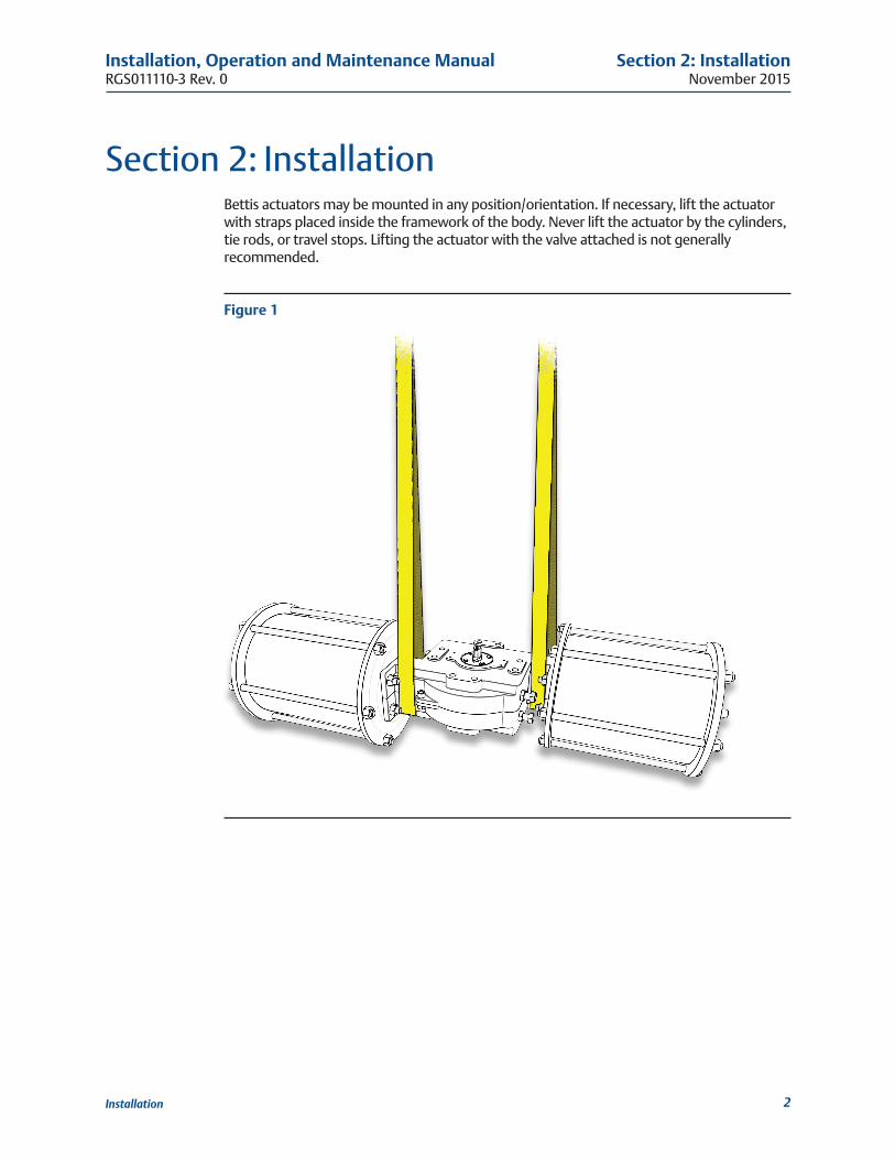
Section 2: InstallationBettis actuators may be mounted in any position/orientation. If necessary, lift the actuator with straps placed inside the framework of the body. Never lift the actuator by the cylinders, tie rods, or travel stops. Lifting the actuator with the valve attached is not generally recommended.
Figure 1
November 2015
Installation, Operation and Maintenance ManualRGS011110-3 Rev. 0
3
Section 2: Installation
Installation
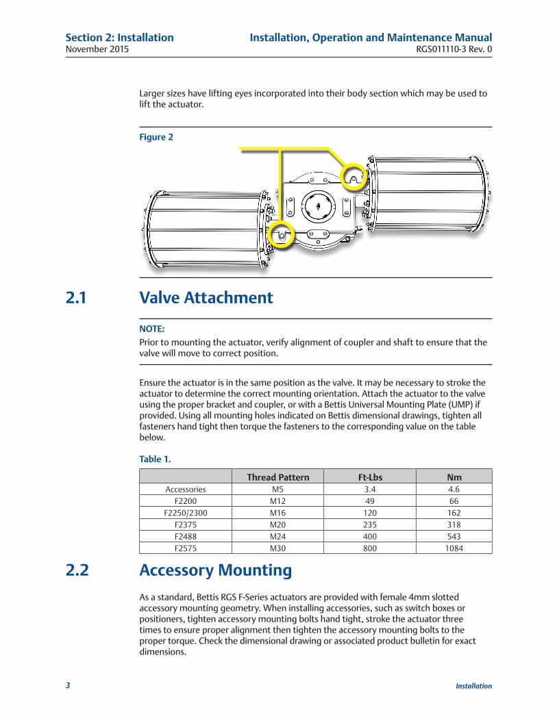
Larger sizes have lifting eyes incorporated into their body section which may be used to lift the actuator.
Figure 2
2�1 Valve Attachment
NOTE: Prior to mounting the actuator, verify alignment of coupler and shaft to ensure that the valve will move to correct position.
Ensure the actuator is in the same position as the valve. It may be necessary to stroke the actuator to determine the correct mounting orientation. Attach the actuator to the valve using the proper bracket and coupler, or with a Bettis Universal Mounting Plate (UMP) if provided. Using all mounting holes indicated on Bettis dimensional drawings, tighten all fasteners hand tight then torque the fasteners to the corresponding value on the table below.
Table 1�
Thread Pattern Ft-Lbs NmAccessories M5 3.4 4.6
F2200 M12 49 66F2250/2300 M16 120 162
F2375 M20 235 318F2488 M24 400 543F2575 M30 800 1084
2�2 Accessory MountingAs a standard, Bettis RGS F-Series actuators are provided with female 4mm slotted accessory mounting geometry. When installing accessories, such as switch boxes or positioners, tighten accessory mounting bolts hand tight, stroke the actuator three times to ensure proper alignment then tighten the accessory mounting bolts to the proper torque. Check the dimensional drawing or associated product bulletin for exact dimensions.
Installation, Operation and Maintenance ManualRGS011110-3 Rev. 0
November 2015
4
Section 2: Installation
Installation
2�3 Piping and OperationThe operation of a Bettis RGS F-Series Spring-Return (SR) actuator is comparable to any spring-return scotch yoke actuator. Instrument air, water, and other power gases and fluids may be used to cycle the actuator so long as construction materials were chosen accordingly and maximum allowable pressure is not exceeded. Air driven stainless-steel actuators with stainless-steel or composite cylinders are not harmed by wet air (so long as freezing does not occur). Aluminum and chrome-plated steel cylinders may be harmed over time by the presence of water.
WARNING: DO NOT EXCEED PRESSURE RATINGExceeding the stated maximum pressure may result in damage to equipment and danger to personnel including severe injury or death. Consult the actuator label for operating limits. If an actuator label is missing, contact Bettis to request a replacement.
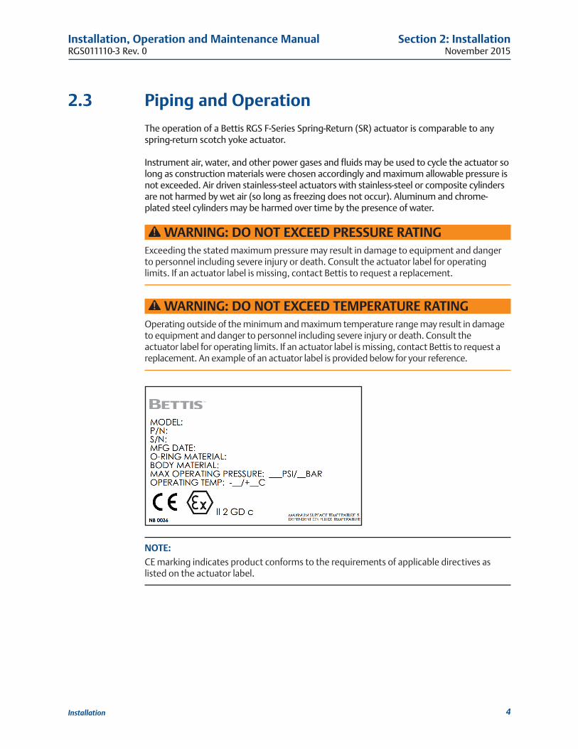
WARNING: DO NOT EXCEED TEMPERATURE RATINGOperating outside of the minimum and maximum temperature range may result in damage to equipment and danger to personnel including severe injury or death. Consult the actuator label for operating limits. If an actuator label is missing, contact Bettis to request a replacement. An example of an actuator label is provided below for your reference.
NOTE: CE marking indicates product conforms to the requirements of applicable directives as listed on the actuator label.
November 2015
Installation, Operation and Maintenance ManualRGS011110-3 Rev. 0
5
Section 2: Installation
Installation
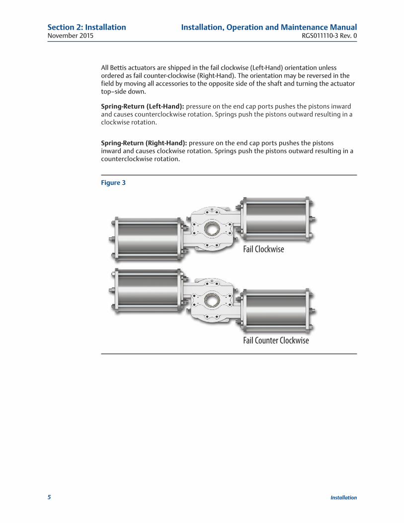
All Bettis actuators are shipped in the fail clockwise (Left-Hand) orientation unless ordered as fail counter-clockwise (Right-Hand). The orientation may be reversed in the field by moving all accessories to the opposite side of the shaft and turning the actuator top–side down.
Spring-Return (Left-Hand): pressure on the end cap ports pushes the pistons inward and causes counterclockwise rotation. Springs push the pistons outward resulting in a clockwise rotation.
Spring-Return (Right-Hand): pressure on the end cap ports pushes the pistons inward and causes clockwise rotation. Springs push the pistons outward resulting in a counterclockwise rotation.
Figure 3
Fail Clockwise
Fail Counter Clockwise
Installation, Operation and Maintenance ManualRGS011110-3 Rev. 0
November 2015
6
Section 2: Installation
Installation
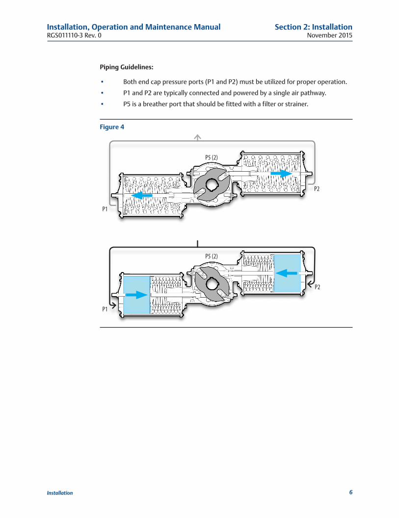
Piping Guidelines:
• Both end cap pressure ports (P1 and P2) must be utilized for proper operation.
• P1 and P2 are typically connected and powered by a single air pathway.
• P5 is a breather port that should be fitted with a filter or strainer.
Figure 4
P1
P2
P1
P2
P5 (2)
P5 (2)
November 2015
Installation, Operation and Maintenance ManualRGS011110-3 Rev. 0
7
Section 2: Installation
Installation
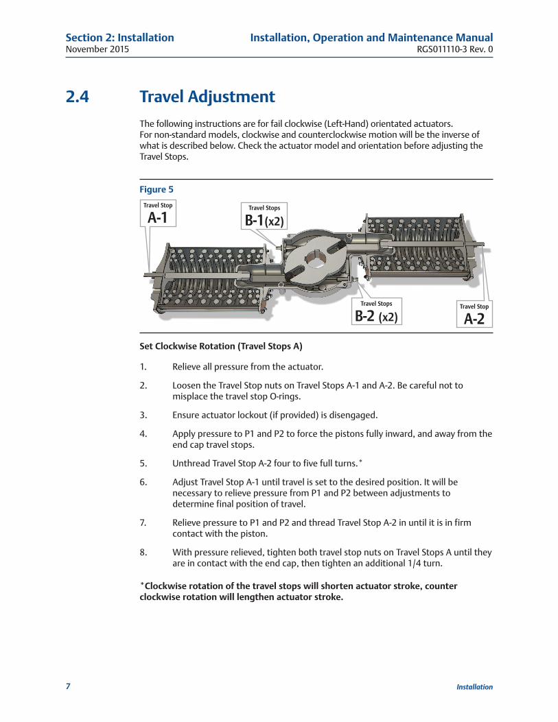
2�4 Travel AdjustmentThe following instructions are for fail clockwise (Left-Hand) orientated actuators. For non-standard models, clockwise and counterclockwise motion will be the inverse of what is described below. Check the actuator model and orientation before adjusting the Travel Stops.
Figure 5
Travel Stop
A-1Travel Stops
B-1(x2)
Travel Stops
B-2 (x2)Travel Stop
A-2
Set Clockwise Rotation (Travel Stops A)
1. Relieve all pressure from the actuator.
2. Loosen the Travel Stop nuts on Travel Stops A-1 and A-2. Be careful not to misplace the travel stop O-rings.
3. Ensure actuator lockout (if provided) is disengaged.
4. Apply pressure to P1 and P2 to force the pistons fully inward, and away from the end cap travel stops.
5. Unthread Travel Stop A-2 four to five full turns.*
6. Adjust Travel Stop A-1 until travel is set to the desired position. It will be necessary to relieve pressure from P1 and P2 between adjustments to determine final position of travel.
7. Relieve pressure to P1 and P2 and thread Travel Stop A-2 in until it is in firm contact with the piston.
8. With pressure relieved, tighten both travel stop nuts on Travel Stops A until they are in contact with the end cap, then tighten an additional 1/4 turn.
*Clockwise rotation of the travel stops will shorten actuator stroke, counter clockwise rotation will lengthen actuator stroke�
Installation, Operation and Maintenance ManualRGS011110-3 Rev. 0
November 2015
8
Section 2: Installation
Installation
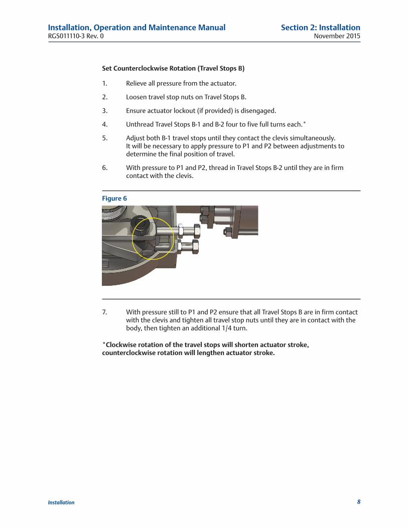
Set Counterclockwise Rotation (Travel Stops B)
1. Relieve all pressure from the actuator.
2. Loosen travel stop nuts on Travel Stops B.
3. Ensure actuator lockout (if provided) is disengaged.
4. Unthread Travel Stops B-1 and B-2 four to five full turns each.*
5. Adjust both B-1 travel stops until they contact the clevis simultaneously. It will be necessary to apply pressure to P1 and P2 between adjustments to determine the final position of travel.
6. With pressure to P1 and P2, thread in Travel Stops B-2 until they are in firm contact with the clevis.
Figure 6
7. With pressure still to P1 and P2 ensure that all Travel Stops B are in firm contact with the clevis and tighten all travel stop nuts until they are in contact with the body, then tighten an additional 1/4 turn.
*Clockwise rotation of the travel stops will shorten actuator stroke, counterclockwise rotation will lengthen actuator stroke�
November 2015
Installation, Operation and Maintenance ManualRGS011110-3 Rev. 0
9
Section 3: Troubleshooting
Troubleshooting
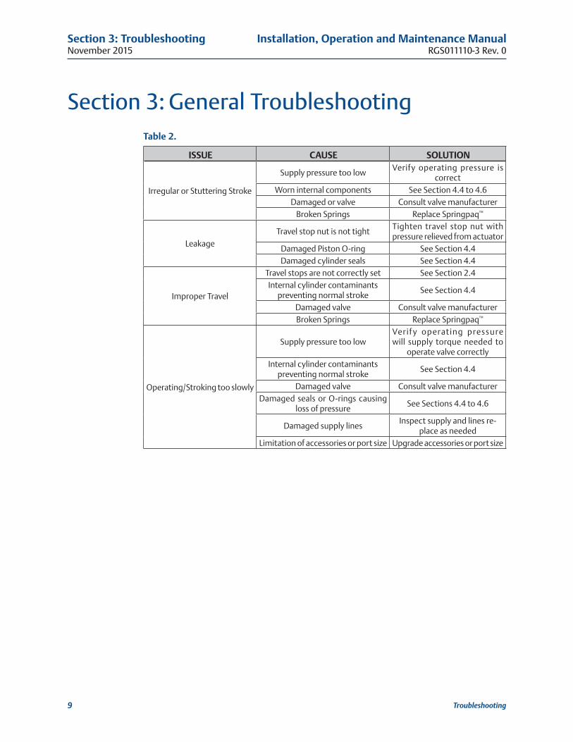
Section 3: General TroubleshootingTable 2�
ISSUE CAUSE SOLUTION
Irregular or Stuttering Stroke
Supply pressure too lowVerify operating pressure is
correctWorn internal components See Section 4.4 to 4.6
Damaged or valve Consult valve manufacturerBroken Springs Replace Springpaq™
LeakageTravel stop nut is not tight
Tighten travel stop nut with pressure relieved from actuator
Damaged Piston O-ring See Section 4.4Damaged cylinder seals See Section 4.4
Improper Travel
Travel stops are not correctly set See Section 2.4Internal cylinder contaminants
preventing normal strokeSee Section 4.4
Damaged valve Consult valve manufacturerBroken Springs Replace Springpaq™
Operating/Stroking too slowly
Supply pressure too lowVerif y operating pressure will supply torque needed to
operate valve correctlyInternal cylinder contaminants
preventing normal strokeSee Section 4.4
Damaged valve Consult valve manufacturerDamaged seals or O-rings causing
loss of pressureSee Sections 4.4 to 4.6
Damaged supply linesInspect supply and lines re-
place as neededLimitation of accessories or port size Upgrade accessories or port size
Installation, Operation and Maintenance ManualRGS011110-3 Rev. 0
November 2015
10
Section 4: Maintenance
Maintenance
Section 4: Maintenance
4�1 Periodic Maintenance ScheduleGeneral service actuators do not require periodic maintenance. Severe service actuators may require periodic maintenance based on operating conditions. Severe service may include but is not limited to high speed, high cycle, highly corrosive, explosive atmosphere, and others. Special applications may require individual maintenance schedules. Contact Bettis for help developing a maintenance schedule for your application.
NOTE:This product is only intended for use in large-scale fixed installations excluded from the scope of Directive 2011/65/EU on the restriction of the use of certain hazardous substances in electrical and electronic equipment (RoHS 2).
4�2 LubricationBettis actuators are lubricated for life. For special applications, grease fittings may be provided. Use the grease fittings (if applicable) incorporated into the torque module of your actuator to apply additional lubricant. The frequency of this lubrication will depend on the application of the actuator. For any questions regarding the frequency of this operation or appropriate lubrication compounds, contact your Bettis distributor.
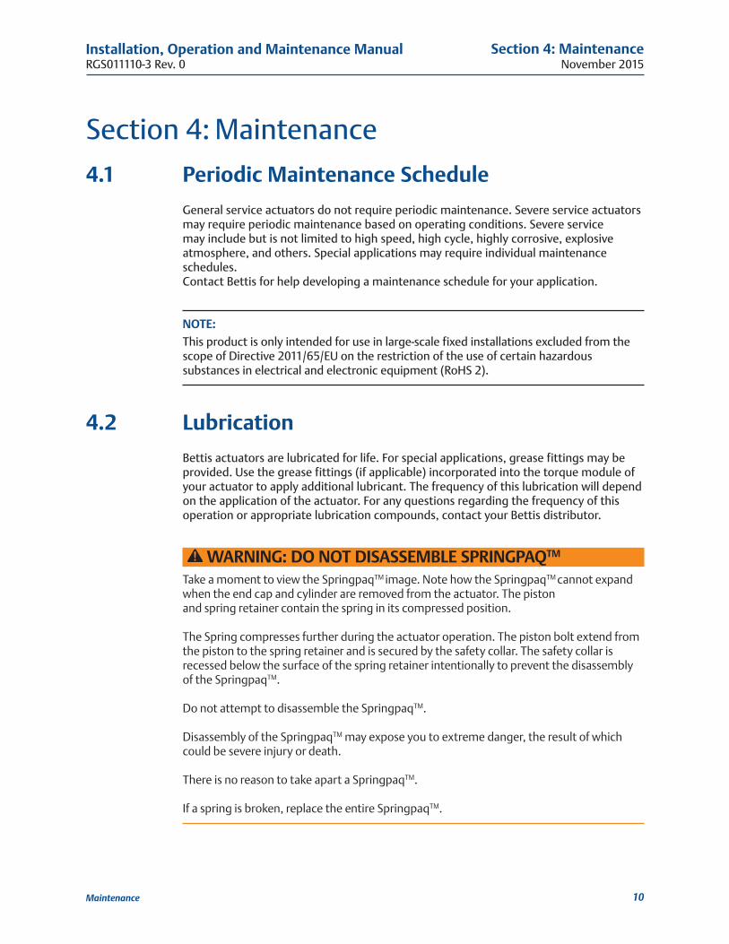
WARNING: DO NOT DISASSEMBLE SPRINGPAQTM
Take a moment to view the SpringpaqTM image. Note how the SpringpaqTM cannot expand when the end cap and cylinder are removed from the actuator. The piston and spring retainer contain the spring in its compressed position. The Spring compresses further during the actuator operation. The piston bolt extend from the piston to the spring retainer and is secured by the safety collar. The safety collar is recessed below the surface of the spring retainer intentionally to prevent the disassembly of the SpringpaqTM. Do not attempt to disassemble the SpringpaqTM. Disassembly of the SpringpaqTM may expose you to extreme danger, the result of which could be severe injury or death. There is no reason to take apart a SpringpaqTM. If a spring is broken, replace the entire SpringpaqTM.
November 2015
Installation, Operation and Maintenance ManualRGS011110-3 Rev. 0
11
Section 4: Maintenance
Maintenance
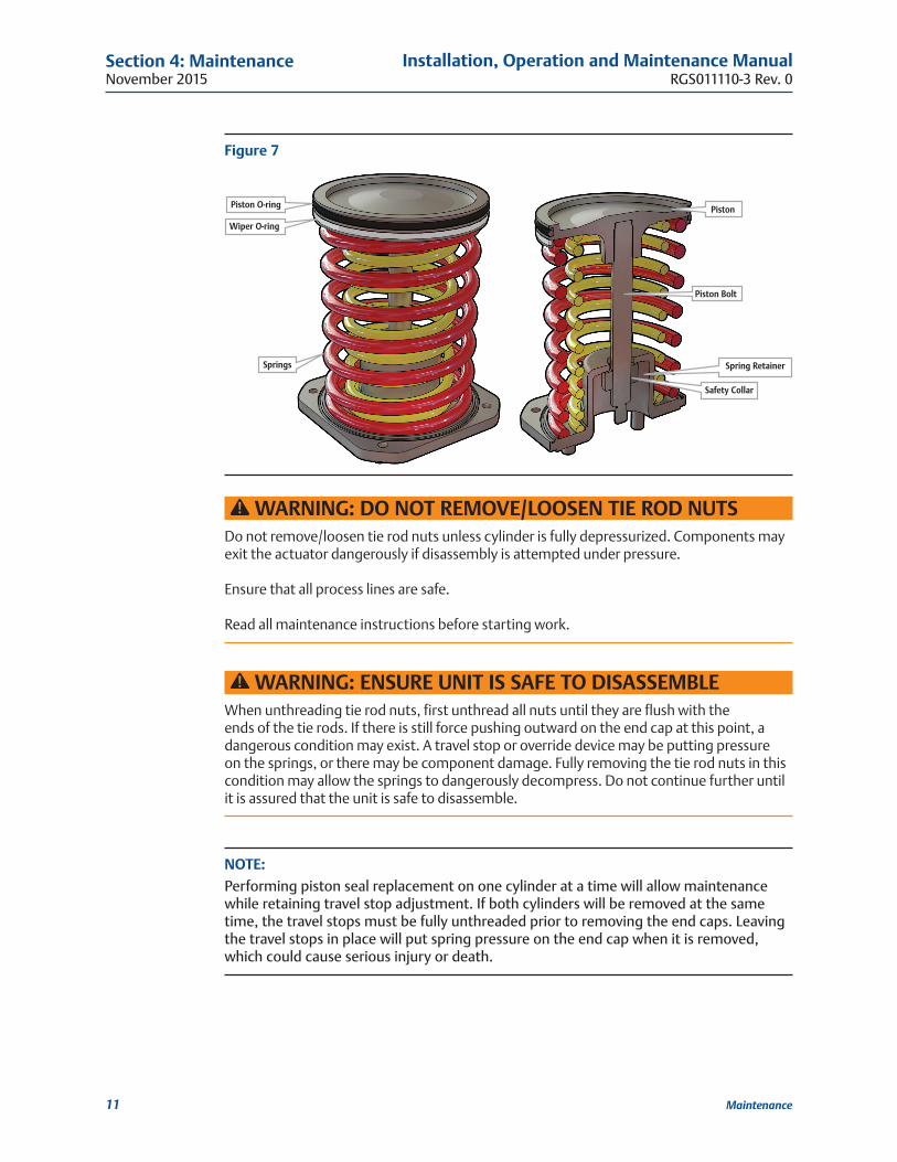
Figure 7
Piston O-ring
Wiper O-ring
Springs
Piston
Safety Collar
Piston Bolt
Spring Retainer
WARNING: DO NOT REMOVE/LOOSEN TIE ROD NUTSDo not remove/loosen tie rod nuts unless cylinder is fully depressurized. Components may exit the actuator dangerously if disassembly is attempted under pressure. Ensure that all process lines are safe. Read all maintenance instructions before starting work.
WARNING: ENSURE UNIT IS SAFE TO DISASSEMBLEWhen unthreading tie rod nuts, first unthread all nuts until they are flush with the ends of the tie rods. If there is still force pushing outward on the end cap at this point, a dangerous condition may exist. A travel stop or override device may be putting pressure on the springs, or there may be component damage. Fully removing the tie rod nuts in this condition may allow the springs to dangerously decompress. Do not continue further until it is assured that the unit is safe to disassemble.
NOTE: Performing piston seal replacement on one cylinder at a time will allow maintenance while retaining travel stop adjustment. If both cylinders will be removed at the same time, the travel stops must be fully unthreaded prior to removing the end caps. Leaving the travel stops in place will put spring pressure on the end cap when it is removed, which could cause serious injury or death.
Installation, Operation and Maintenance ManualRGS011110-3 Rev. 0
November 2015
12
Section 4: Maintenance
Maintenance
4�3 Maintenance KitTo purchase your actuator maintenance kit, contact your Bettis distributor. Please have the serial number of your actuator available. This number may be found on the actuator label or stamped into the body of the actuator.
4�4 Piston Seal Replacement1. Exhaust all pressure and disconnect all supply lines.
2. Loosen all tie rod nuts until they are flush with the ends of the tie rods.
3. Check that there is no pressure against the end cap by verifying that the end cap is not being forced against the tie rod nuts.
WARNING: EXHAUST ALL PRESSURE AGAINST END CAPIf there is force against the end cap, stop. Do not continue further until it is assured that the unit is safe to disassemble.
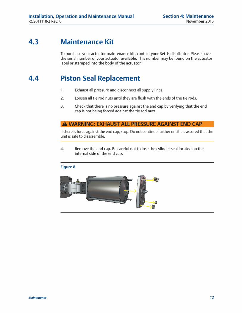
4. Remove the end cap. Be careful not to lose the cylinder seal located on the internal side of the end cap.
Figure 8
November 2015
Installation, Operation and Maintenance ManualRGS011110-3 Rev. 0
13
Section 4: Maintenance
Maintenance
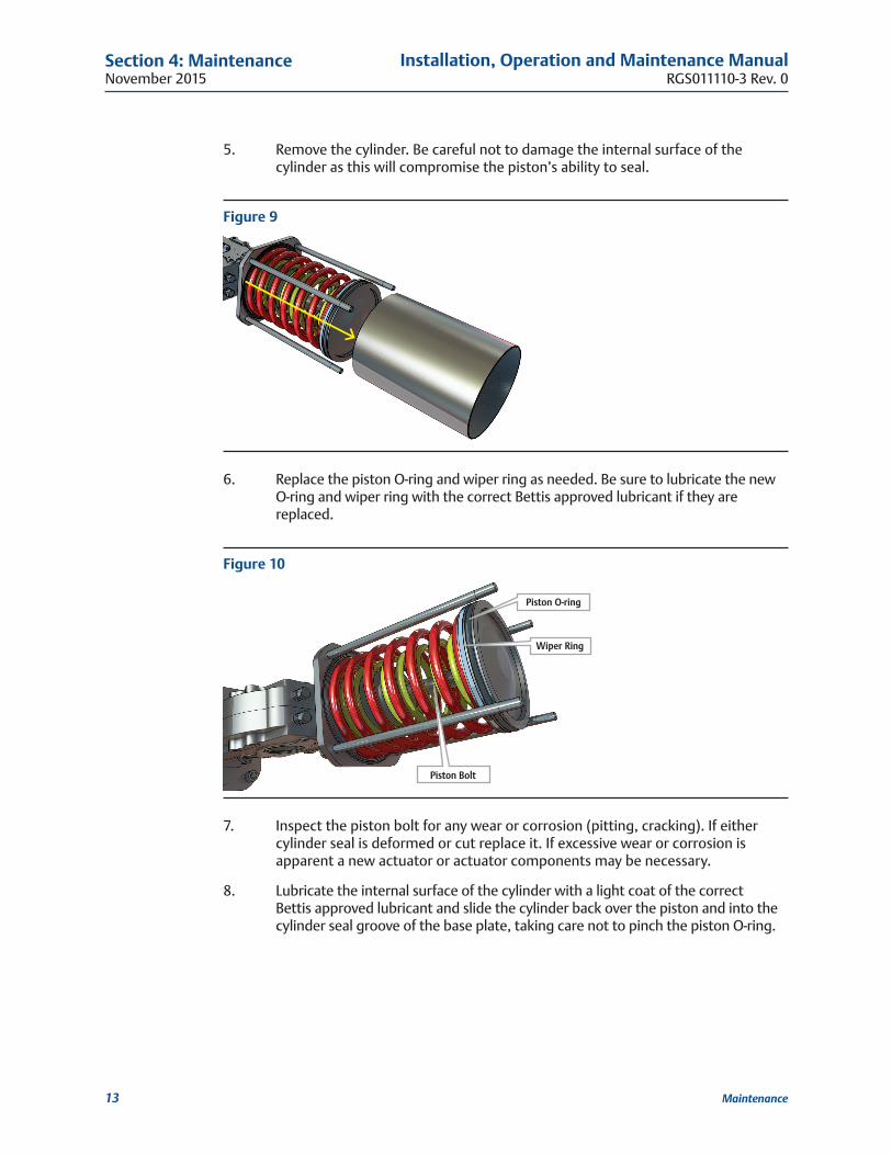
5. Remove the cylinder. Be careful not to damage the internal surface of the cylinder as this will compromise the piston’s ability to seal.
Figure 9
6. Replace the piston O-ring and wiper ring as needed. Be sure to lubricate the new O-ring and wiper ring with the correct Bettis approved lubricant if they are replaced.
Figure 10
Piston O-ring
Wiper Ring
Piston Bolt
7. Inspect the piston bolt for any wear or corrosion (pitting, cracking). If either cylinder seal is deformed or cut replace it. If excessive wear or corrosion is apparent a new actuator or actuator components may be necessary.
8. Lubricate the internal surface of the cylinder with a light coat of the correct Bettis approved lubricant and slide the cylinder back over the piston and into the cylinder seal groove of the base plate, taking care not to pinch the piston O-ring.
Installation, Operation and Maintenance ManualRGS011110-3 Rev. 0
November 2015
14
Section 4: Maintenance
Maintenance
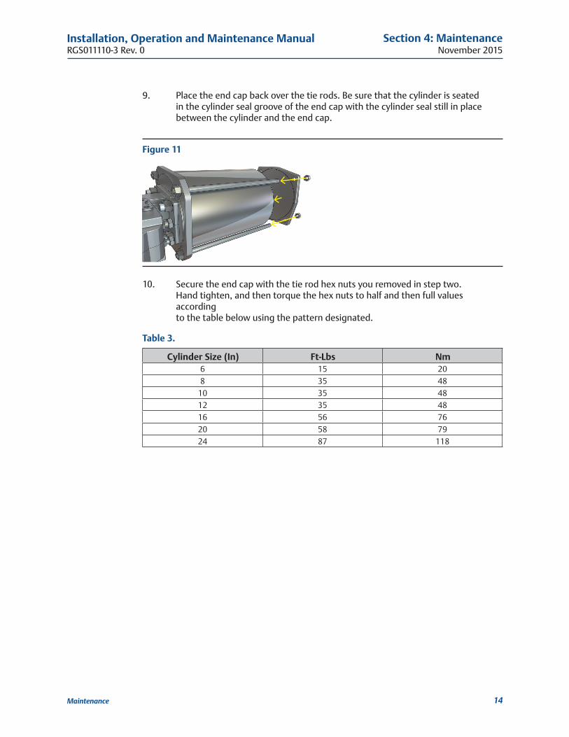
9. Place the end cap back over the tie rods. Be sure that the cylinder is seated in the cylinder seal groove of the end cap with the cylinder seal still in place between the cylinder and the end cap.
Figure 11
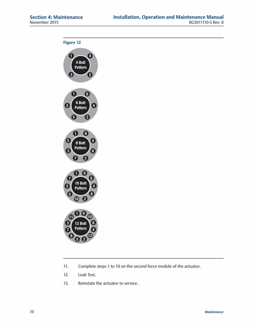
10. Secure the end cap with the tie rod hex nuts you removed in step two. Hand tighten, and then torque the hex nuts to half and then full values according to the table below using the pattern designated.
Table 3�
Cylinder Size (In) Ft-Lbs Nm6 15 208 35 48
10 35 4812 35 4816 56 7620 58 7924 87 118
November 2015
Installation, Operation and Maintenance ManualRGS011110-3 Rev. 0
15
Section 4: Maintenance
Maintenance
Figure 12
4 BoltPattern
1 4
23
1
3
5 2
4
6
6 BoltPattern
12 BoltPattern
111
37
95 2
1248
106
10 BoltPattern
1
810
5
3
7
2
96
4
8 BoltPattern
1
2
3
45
67
8
11. Complete steps 1 to 10 on the second force module of the actuator.
12. Leak Test.
13. Reinstate the actuator to service.
Installation, Operation and Maintenance ManualRGS011110-3 Rev. 0
November 2015
16
Section 4: Maintenance
Maintenance
4�5 Yoke Seal and Bushing ReplacementIn Bettis RGS F-Series actuators, the yoke seal does not serve any purpose other than to prevent external contaminants from entering the torque module. The following steps can be followed to replace the yoke seal and/or bushings.
1. Depressurize the actuator and remove all supply lines.
2. Remove the actuator from the valve.
3. Ensure lockout (if provided) is disengaged.
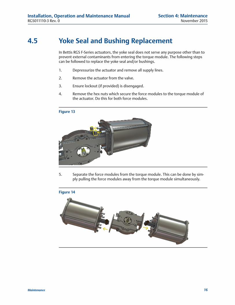
4. Remove the hex nuts which secure the force modules to the torque module of the actuator. Do this for both force modules.
Figure 13
5. Separate the force modules from the torque module. This can be done by sim-ply pulling the force modules away from the torque module simultaneously.
Figure 14
November 2015
Installation, Operation and Maintenance ManualRGS011110-3 Rev. 0
17
Section 4: Maintenance
Maintenance
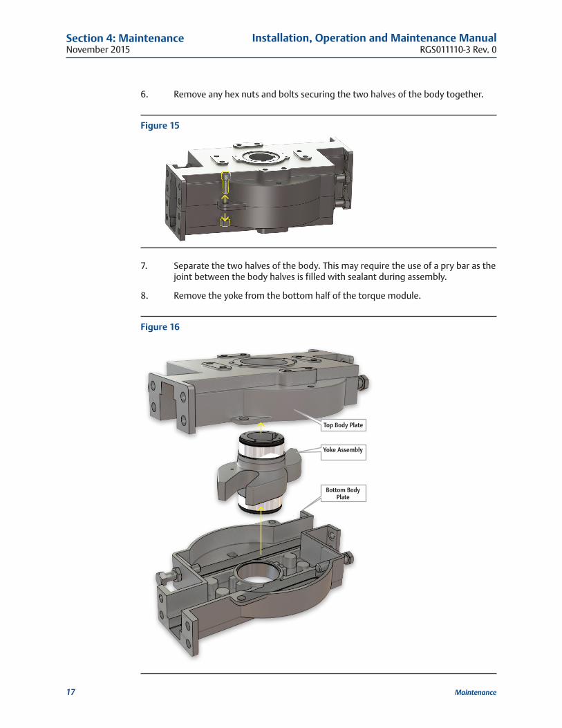
6. Remove any hex nuts and bolts securing the two halves of the body together.
Figure 15
7. Separate the two halves of the body. This may require the use of a pry bar as the joint between the body halves is filled with sealant during assembly.
8. Remove the yoke from the bottom half of the torque module.
Figure 16
Top Body Plate
Yoke Assembly
Bottom Body Plate
Installation, Operation and Maintenance ManualRGS011110-3 Rev. 0
November 2015
18
Section 4: Maintenance
Maintenance
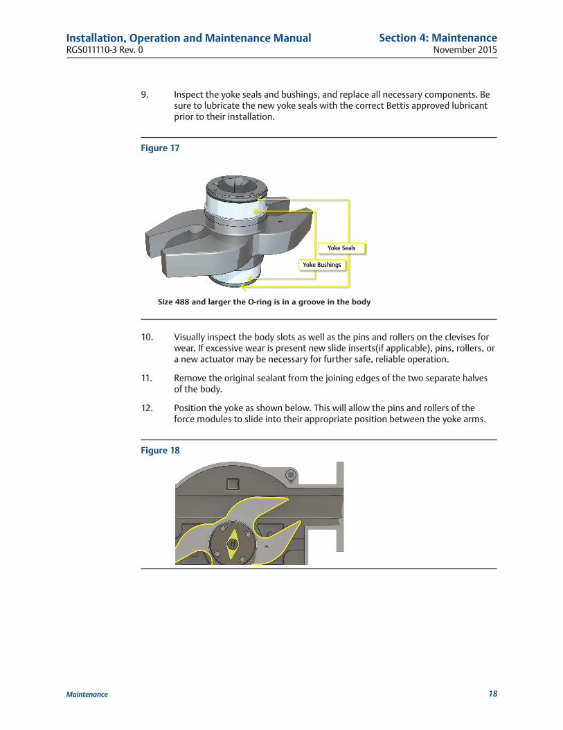
9. Inspect the yoke seals and bushings, and replace all necessary components. Be sure to lubricate the new yoke seals with the correct Bettis approved lubricant prior to their installation.
Figure 17
Yoke Seals
Yoke Bushings
10. Visually inspect the body slots as well as the pins and rollers on the clevises for wear. If excessive wear is present new slide inserts(if applicable), pins, rollers, or a new actuator may be necessary for further safe, reliable operation.
11. Remove the original sealant from the joining edges of the two separate halves of the body.
12. Position the yoke as shown below. This will allow the pins and rollers of the force modules to slide into their appropriate position between the yoke arms.
Figure 18
Size 488 and larger the O-ring is in a groove in the body
November 2015
Installation, Operation and Maintenance ManualRGS011110-3 Rev. 0
19
Section 4: Maintenance
Maintenance
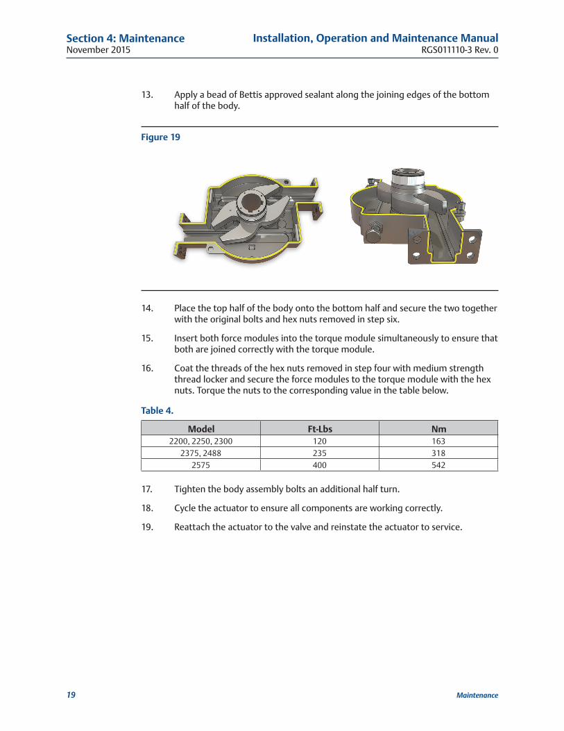
13. Apply a bead of Bettis approved sealant along the joining edges of the bottom half of the body.
Figure 19
14. Place the top half of the body onto the bottom half and secure the two together with the original bolts and hex nuts removed in step six.
15. Insert both force modules into the torque module simultaneously to ensure that both are joined correctly with the torque module.
16. Coat the threads of the hex nuts removed in step four with medium strength thread locker and secure the force modules to the torque module with the hex nuts. Torque the nuts to the corresponding value in the table below.
Table 4�
Model Ft-Lbs Nm2200, 2250, 2300 120 163
2375, 2488 235 3182575 400 542
17. Tighten the body assembly bolts an additional half turn.
18. Cycle the actuator to ensure all components are working correctly.
19. Reattach the actuator to the valve and reinstate the actuator to service.
Installation, Operation and Maintenance ManualRGS011110-3 Rev. 0
November 2015
20
Section 4: Maintenance
Maintenance
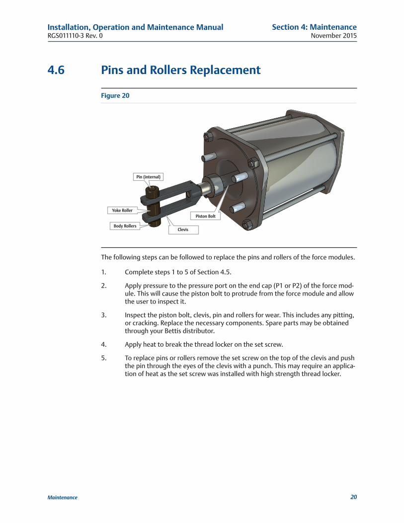
4�6 Pins and Rollers Replacement
Figure 20
Pin (internal)
Body Rollers
Yoke RollerPiston Bolt
Clevis
The following steps can be followed to replace the pins and rollers of the force modules.
1. Complete steps 1 to 5 of Section 4.5.
2. Apply pressure to the pressure port on the end cap (P1 or P2) of the force mod-ule. This will cause the piston bolt to protrude from the force module and allow the user to inspect it.
3. Inspect the piston bolt, clevis, pin and rollers for wear. This includes any pitting, or cracking. Replace the necessary components. Spare parts may be obtained through your Bettis distributor.
4. Apply heat to break the thread locker on the set screw.
5. To replace pins or rollers remove the set screw on the top of the clevis and push the pin through the eyes of the clevis with a punch. This may require an applica-tion of heat as the set screw was installed with high strength thread locker.
November 2015
Installation, Operation and Maintenance ManualRGS011110-3 Rev. 0
21
Section 4: Maintenance
Maintenance
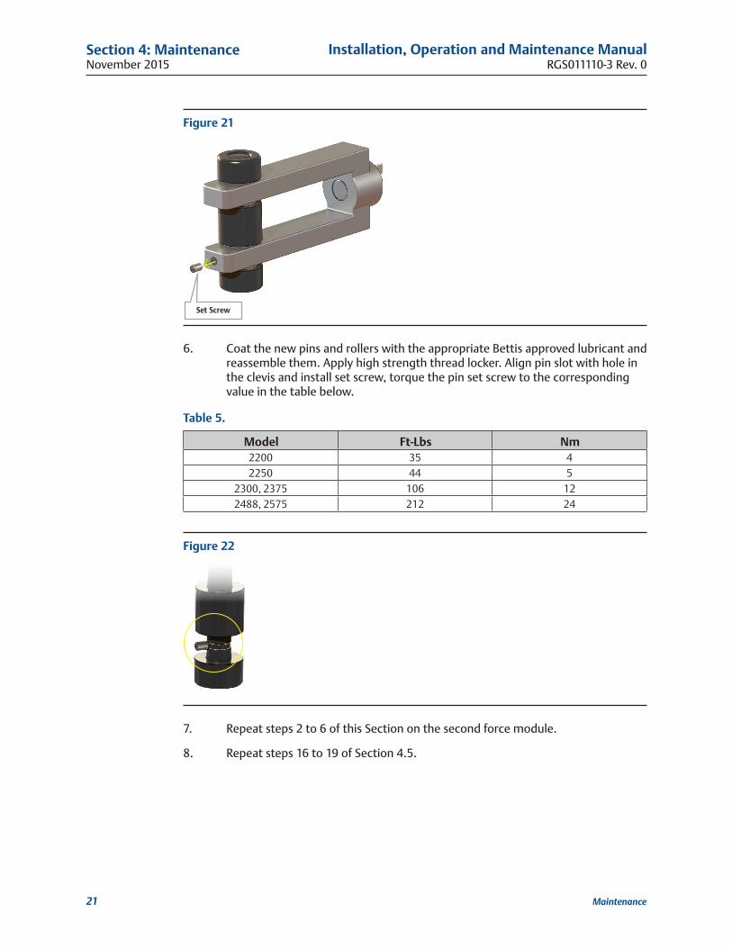
Figure 21
Set Screw
6. Coat the new pins and rollers with the appropriate Bettis approved lubricant and reassemble them. Apply high strength thread locker. Align pin slot with hole in the clevis and install set screw, torque the pin set screw to the corresponding value in the table below.
Table 5�
Model Ft-Lbs Nm2200 35 42250 44 5
2300, 2375 106 122488, 2575 212 24
Figure 22
7. Repeat steps 2 to 6 of this Section on the second force module.
8. Repeat steps 16 to 19 of Section 4.5.
Installation, Operation and Maintenance ManualRGS011110-3 Rev. 0
November 2015
22
Appendix
Appendix
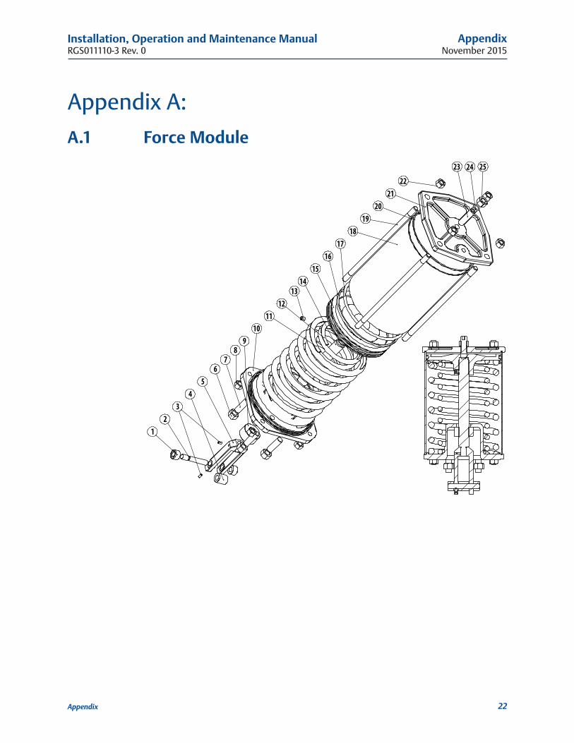
Appendix A:
A�1 Force Module
12
3
9
19
1716
15
22
18
2523 24
21
1314
1211
4
67
20
10
5
8
November 2015
Installation, Operation and Maintenance ManualRGS011110-3 Rev. 0
23
Appendix
Appendix
4�6�1 Force Module Part Number
Number Part1 Body Roller2 Pin3 Pin Set Screw4 Yoke Roller5 Clevis6 Hex Nut, FM Mount7 Stud8 Hex Nut, Tie Rod9 Safety Collar
10 Spring Retainer11 External Spring(s)12 Internal Spring(s)13 Piston Set Screw14 Piston Bolt15 Piston16 Wiper Ring17 Piston O-ring18 Cylinder19 Tie Rod20 Cylinder Seal21 End Cap22 Tie Rod Nut23 Travel Stop A24 Travel Stop O-ring25 Travel Stop Nut A
Installation, Operation and Maintenance ManualRGS011110-3 Rev. 0
November 2015
24
Appendix
Appendix
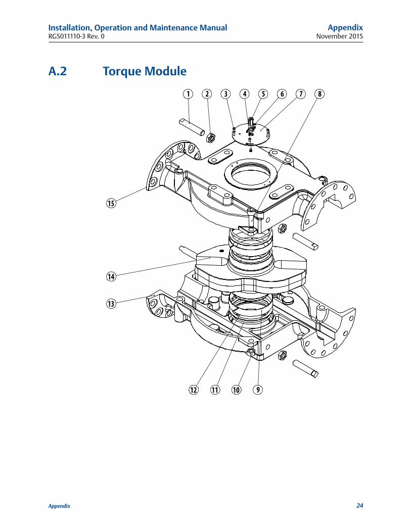
A�2 Torque Module
3 4 5 6 7
15
12
8
14
13
1
911
2
10
November 2015
Installation, Operation and Maintenance ManualRGS011110-3 Rev. 0
25
Appendix
Appendix
4�6�2 Torque Module Part Number
Number Part1 Travel Stop B2 Travel Stops Nut B3 Top Hat Mounting Bolt4 Top Hat Bolt5 Top Hat6 Top Hat Indicator7 Top Hat Base8 Body Assembly Bolt9 Yoke Bushing
10 Body Assembly Nuts11 Yoke O-ring12 Yoke Thrust Washer13 Body Bottom14 Yoke15 Body Top

For complete list of sales and manufacturing sites, please visit www.emerson.com/actuationtechnologieslocations or contact us at [email protected]
World Area Confi guration Centers (WACC) offer sales support, service, inventory and commissioning to our global customers. Choose the WACC or sales offi ce nearest you:
NORTH & SOUTH AMERICA
19200 Northwest FreewayHouston TX 77065USAT +1 281 477 4100
Av. Hollingsworth 325 Iporanga Sorocaba SP 18087-105BrazilT +55 15 3413 8888
ASIA PACIFIC
No. 9 Gul Road#01-02 Singapore 629361T +65 6777 8211
No. 1 Lai Yuan RoadWuqing Development AreaTianjin 301700P. R. ChinaT +86 22 8212 3300
MIDDLE EAST & AFRICA
P. O. Box 17033Jebel Ali Free ZoneDubaiT +971 4 811 8100
P. O. Box 10305Jubail 31961Saudi ArabiaT +966 3 340 8650
24 Angus CrescentLongmeadow Business Estate East P.O. Box 6908 Greenstone 1616 Modderfontein Extension 5South AfricaT +27 11 451 3700
EUROPE
Holland Fasor 6Székesfehérvár 8000HungaryT +36 22 53 09 50
Strada Biffi 16529017 Fiorenzuola d’Arda (PC)ItalyT +39 0523 944 411
www.emerson.com/bettis
©2018 Emerson. All rights reserved.
The Emerson logo is a trademark and service mark of Emerson Electric Co. BettisTM is a mark of one of the Emerson family of companies. All other marks are property of their respective owners.
The contents of this publication are presented for information purposes only, and while every effort has been made to ensure their accuracy, they are not to be construed as warranties or guarantees, express or implied, regarding the products or services described herein or their use or applicability. All sales are governed by our terms and conditions, which are available on request. We reserve the right to modify or improve the designs or specifications of our products at any time without notice.
![Bettis Electric Actuators. [File Name or Event] Emerson Confidential 27-Jun-01, Slide 2 Overview: Bettis electric actuators It is the traditional “EIM”](https://img.pdfslide.net/doc/110x75/56649d0a5503460f949dcc96/bettis-electric-actuators-file-name-or-event-emerson-confidential-27-jun-01.jpg)