Embed Size (px)
Citation preview
BgNS International Conference: Nuclear Energy for the People, 10-13 September 2018, Garden of Eden Resort, Sveti Vlas, Bulgaria
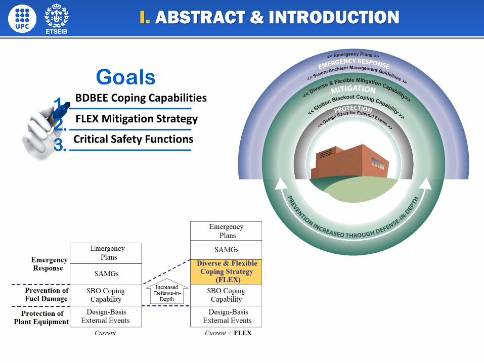
Critical Safety Functions
BDBEE Coping Capabilities
FLEX Mitigation Strategy
I. ABSTRACT & INTRODUCTION
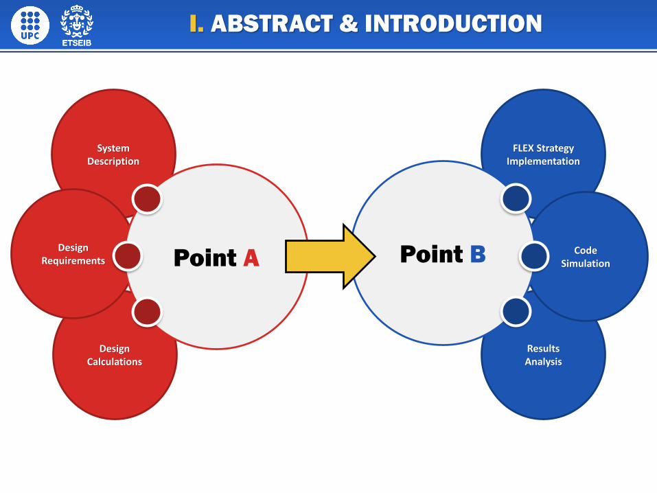
Design Calculations
System Description
Design Requirements Point A
FLEX Strategy Implementation
Results Analysis
Code SimulationPoint B
I. ABSTRACT & INTRODUCTION
II.1 SYSTEMS DESCRIPTION
This page contains a picture that can be switched out for another graphic by right clicking directly on the image and clicking “change picture.” Replace your text here to give a description.
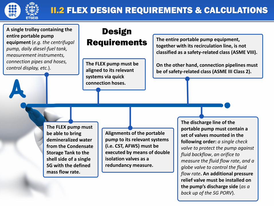
Design
Requirements
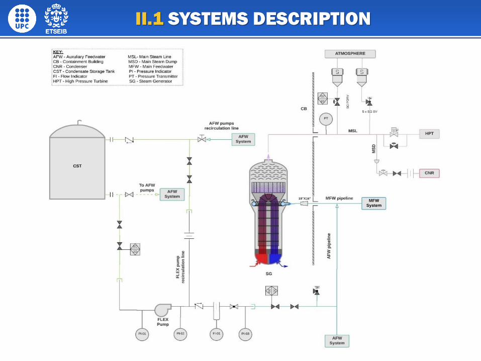
A single trolley containing the entire portable pump equipment (e.g. the centrifugal pump, daily diesel-fuel tank, measurement instruments, connection pipes and hoses, control display, etc.).
The FLEX pump must be aligned to its relevant systems via quick connection hoses.
The entire portable pump equipment, together with its recirculation line, is not classified as a safety-related class (ASME VIII).
On the other hand, connection pipelines must be of safety-related class (ASME III Class 2).
The FLEX pump must be able to bring demineralized water from the Condensate Storage Tank to the shell side of a single SG with the defined mass flow rate.
Alignments of the portable pump to its relevant systems (i.e. CST, AFWS) must be executed by means of double isolation valves as a redundancy measure.
The discharge line of the portable pump must contain a set of valves mounted in the following order: a single check valve to protect the pump against fluid backflow, an orifice to measure the fluid flow rate, and a globe valve to control the fluid flow rate. An additional pressure relief valve must be installed on the pump’s discharge side (as a back up of the SG PORV).
II.2 FLEX DESIGN REQUIREMENTS & CALCULATIONS
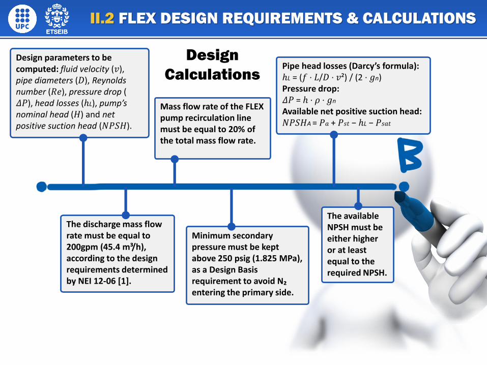
Design parameters to be computed: fluid velocity (𝑣), pipe diameters (𝐷), Reynolds number (𝑅𝑒), pressure drop ( 𝛥𝑃), head losses (ℎL), pump’s nominal head (𝐻) and net positive suction head (𝑁𝑃𝑆𝐻).
Mass flow rate of the FLEX pump recirculation line must be equal to 20% of the total mass flow rate.
Pipe head losses (Darcy’s formula):ℎL = (𝑓 · 𝐿/𝐷 · 𝑣²) / (2 · 𝑔n) Pressure drop:𝛥𝑃 = ℎ · 𝜌 · 𝑔n
Available net positive suction head:𝑁𝑃𝑆𝐻A = 𝑃𝑎 + 𝑃𝑠𝑡 − ℎL − 𝑃𝑠𝑎𝑡
The discharge mass flow rate must be equal to 200gpm (45.4 m³/h), according to the design requirements determined by NEI 12-06 [1].
Minimum secondary pressure must be kept above 250 psig (1.825 MPa), as a Design Basis requirement to avoid N₂entering the primary side.
The available NPSH must be either higher or at least equal to the required NPSH.
Design
Calculations
II.2 FLEX DESIGN REQUIREMENTS & CALCULATIONS
III.1 Nodalization Scheme Characteristics of the Employed NPP Model
A 4-loop Westinghouse-design PWR power plant (Zion NPP)
Two loops in the primary circuit (one loop being connected to the FLEX system andanother one representing the remaining 3 loops of the real NPP)
Reactor SCRAM, RCPs coast-down, MWF pumps and turbine trip (concurrently with theSBO occurrence)
HPIS, LPIS, CVCS, and AFWS not available
ACC tanks not being isolated after their inventory is depleted
Primary coolant leakages through RCP seals represented by gate valves (Aᵥ = 50 cm²)placed right after each RCP
III. FLEX STRATEGY IMPLEMENTATION
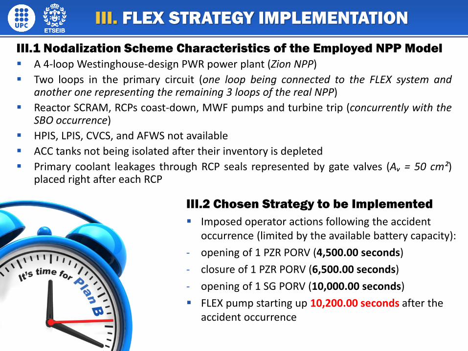
III.2 Chosen Strategy to be Implemented
Imposed operator actions following the accident occurrence (limited by the available battery capacity):
- opening of 1 PZR PORV (4,500.00 seconds)
- closure of 1 PZR PORV (6,500.00 seconds)
- opening of 1 SG PORV (10,000.00 seconds)
FLEX pump starting up 10,200.00 seconds after the accident occurrence
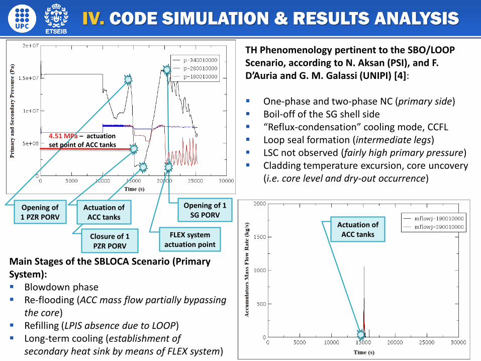
Opening of 1 SG PORV
IV. CODE SIMULATION & RESULTS ANALYSIS
FLEX system actuation point
Opening of 1 PZR PORV
Closure of 1 PZR PORV
Actuation of ACC tanks
4.51 MPa – actuation set point of ACC tanks
Actuation of ACC tanks
TH Phenomenology pertinent to the SBO/LOOP Scenario, according to N. Aksan (PSI), and F. D’Auria and G. M. Galassi (UNIPI) [4]:
One-phase and two-phase NC (primary side) Boil-off of the SG shell side “Reflux-condensation” cooling mode, CCFL Loop seal formation (intermediate legs) LSC not observed (fairly high primary pressure) Cladding temperature excursion, core uncovery
(i.e. core level and dry-out occurrence)
Main Stages of the SBLOCA Scenario (Primary System): Blowdown phase Re-flooding (ACC mass flow partially bypassing
the core) Refilling (LPIS absence due to LOOP) Long-term cooling (establishment of
secondary heat sink by means of FLEX system)

IV. CODE SIMULATION & RESULTS ANALYSIS
Oscillations of the FLEX pump mass flow rate caused by the SG SS boil-off, resulting in an AFW pathway being blocked by the
presence of secondary side vapor
Clearly observed similar pattern of the primary pressure evolution over time and the mass flow rate
of the primary coolant leaking out through the RCP seals
IV. CODE SIMULATION & RESULTS ANALYSIS
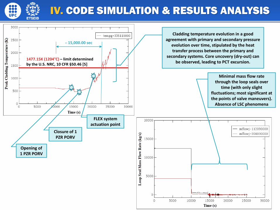
1477.15K (1204°C) – limit determined by the U.S. NRC, 10 CFR §50.46 [5]
FLEX system actuation point
Opening of 1 PZR PORV
Closure of 1 PZR PORV
15,000.00 sec
Minimal mass flow rate through the loop seals over
time (with only slight fluctuations; most significant at the points of valve maneuvers).
Absence of LSC phenomena
Cladding temperature evolution in a good agreement with primary and secondary pressure
evolution over time, stipulated by the heat transfer process between the primary and
secondary systems. Core uncovery (dry-out) can be observed, leading to PCT excursion.
PCT kept below the pre-determined limit of 1204°C for about 15,000.00 seconds (4.17 hours) after the LOOP occurrence
Over-conservative initial and boundary conditions (as compared to the current situation in the commercially operated PWR power units)
More appropriate operator actions may be imposed regarding the timing and sequence of the various valve maneuvers
On-site EDGs, portable DGs and larger number of back-up battery banks usually available in a stand-by mode, and ready to be used when necessary
Availability of state-of-the-art engineering solutions to lessen the consequences of the SBO scenario (e.g. the RCP Sigma Seal and SHIELD Passive Thermal Shutdown Seal for RCPs [6, 7] offered by WEC, as well as the enhanced SFP I&C systems, CFVS, PAR, etc.)
Adequate response by the NPP accident management team and operating personnel guaranteed by properly developed symptom-based EOPs and SAMGs (including procedures and guidelines for low and zero power NPP states), complemented with FLEX implementation guides and consistent communication strategies
Establishment of an off-site AMC and a physically protected housing for multiple sets of portable pumps and power supply equipment to be stored nearby the power plant
V. CONCLUSION & RECOMMENDATIONS
The design calculations and code simulations that are presented inthe current study are based on methodologies and accidentscenarios established by the academic personnel working at theNuclear Engineering Section of the Technical University of Catalunia(UPC-BarcelonaTech). In this regard, all the credits pertaining to thedifferent specifics of the various computational and simulationstages of the chosen scenario should be given to them.
ACKNOWLEDGEMENT
1) Nuclear Energy Institute (NEI), Diverse and Flexible Coping Strategies (FLEX) Implementation Guide, NEI 12- 06, Rev. 3, Washington D.C. (Sep 2016)
2) CRANE CO., Flow of Fluids through Valves, Fittings, and Pipe, Metric Edition – SI Units, Technical Paper No. 410 M, New York (1982)
3) The American Society of Mechanical Engineers, Stainless Steel Pipe, An American National Standard, ASME B36.19M-2004, Revision of ANSI/ASME B36.19M-1985 (Oct 25, 2004)
4) D’Auria, F., Thermal-Hydraulics in Water-Cooled Nuclear Reactors, Woodhead Publishing Series in Energy, An imprint of Elsevier, United Kingdom (2017)
5) U.S. NRC, 10 CFR, §50.46 Acceptance Criteria for Emergency Core Cooling Systems for Light-Water Nuclear Power Reactors, NRC Library, Document Collection, NRC Regulations, URL: https://www.nrc.gov/reading-rm/doc-collections/cfr/part050/part050-0046.html [Page Last Updated: August 29, 2017]
6) Westinghouse Electric Company LLC, Rotating Equipment Services, Reactor Coolant Pump Sigma™ Seal, URL: http://www.westinghousenuclear.com/Portals/0/features/NS-FS-0185%20Sigma%20Seal%20final.pdf [November 2017/NS-FS-0185]
7) Westinghouse Electric Company LLC, Rotating Equipment Services, SHIELD® Passive Thermal Shutdown Seal for Reactor Coolant Pumps, URL: http://www.westinghousenuclear.com/Portals/0/features/NS-FS- 0106%20SHIELD%20final.pdf [November 2017/NS-FS-0106]
REFERENCES


![Riproduzione [modalit. compatibilit.] - Docenti Unifedocente.unife.it/simonetta.pancaldi/insegnamento-di-botanica/... · Gli organismi generati per mitosi da cellule “capostipiti”](https://img.pdfslide.net/doc/110x75/5c658d2409d3f29b6e8cf03a/riproduzione-modalit-compatibilit-docenti-gli-organismi-generati-per-mitosi.jpg)