Embed Size (px)
Citation preview

BGT SeriesLow Pressure Filters
60
61
BGT SeriesApplications
Specifications
Housing Data:Material: Head – Aluminum Alloy Diffusor – Steel Internals – Carbon Steel and Aluminum Seals – Nitrile (Standard), FluorocarbonPressure Rating: Static – 150 psi (10.3 bar)Temperature Range: Operating -40°F to +250°F (-40°C to +120°C)
- Flows to 640 GPM
- 3 Micron Absolute to 120 Micron Absolute
- Disposable or Recleanable Elements
- Visual and Electrical Indicators
- Microglass elements
- Magnetic prefiltration
- Full flow bypass valve
- No internal leakage paths
- Inside-to-out flow thru element
- Complete contaminant removal during
element service
- LEIF® element (600 and 1000 Series only)
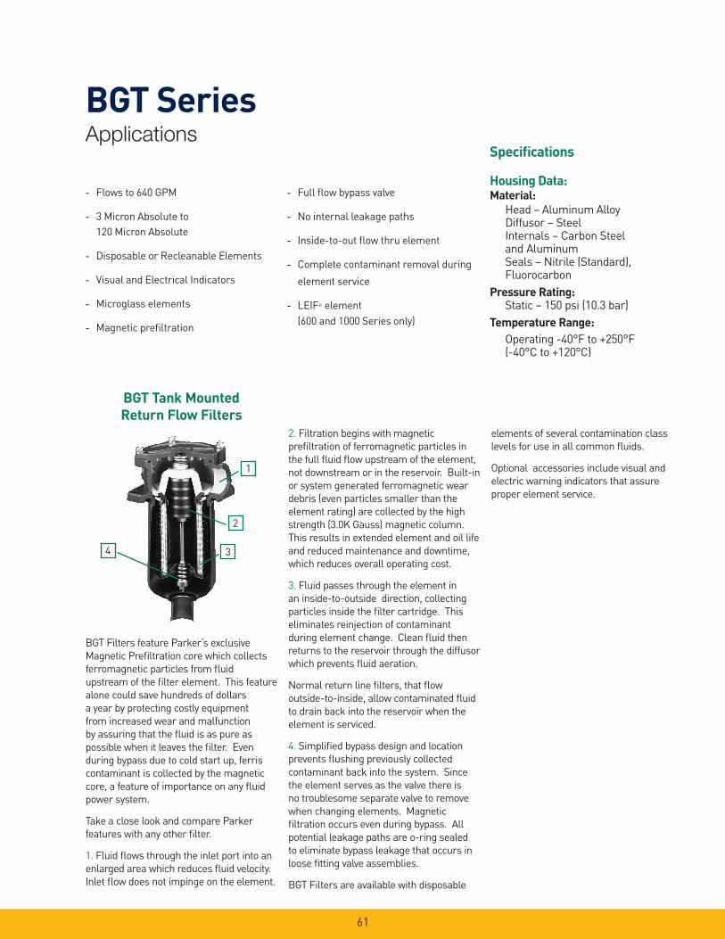
BGT Tank Mounted Return Flow Filters
BGT Filters feature Parker’s exclusive Magnetic Prefiltration core which collects ferromagnetic particles from fluid upstream of the filter element. This feature alone could save hundreds of dollars a year by protecting costly equipment from increased wear and malfunction by assuring that the fluid is as pure as possible when it leaves the filter. Even during bypass due to cold start up, ferris contaminant is collected by the magnetic core, a feature of importance on any fluid power system.
Take a close look and compare Parker features with any other filter.
1. Fluid flows through the inlet port into an enlarged area which reduces fluid velocity. Inlet flow does not impinge on the element.
2. Filtration begins with magnetic prefiltration of ferromagnetic particles in the full fluid flow upstream of the element, not downstream or in the reservoir. Built-in or system generated ferromagnetic wear debris (even particles smaller than the element rating) are collected by the high strength (3.0K Gauss) magnetic column. This results in extended element and oil life and reduced maintenance and downtime, which reduces overall operating cost.
3. Fluid passes through the element in an inside-to-outside direction, collecting particles inside the filter cartridge. This eliminates reinjection of contaminant during element change. Clean fluid then returns to the reservoir through the diffusor which prevents fluid aeration.
Normal return line filters, that flow outside-to-inside, allow contaminated fluid to drain back into the reservoir when the element is serviced.
4. Simplified bypass design and location prevents flushing previously collected contaminant back into the system. Since the element serves as the valve there is no troublesome separate valve to remove when changing elements. Magnetic filtration occurs even during bypass. All potential leakage paths are o-ring sealed to eliminate bypass leakage that occurs in loose fitting valve assemblies.
BGT Filters are available with disposable
elements of several contamination class levels for use in all common fluids.
Optional accessories include visual and electric warning indicators that assure proper element service.
4
1
2
3
62
BGT Series
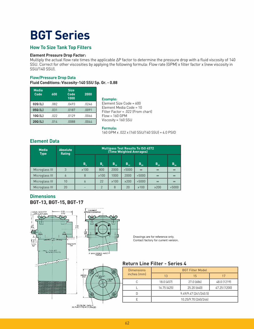
DimensionsBGT-13, BGT-15, BGT-17
Example:Element Size Code = 600Element Media Code = 10Filter Factor = .022 (From chart)Flow = 160 GPMViscosity = 160 SSU
Formula: 160 GPM x .022 x (160 SSU/140 SSU) = 4.0 PSID
How To Size Tank Top FiltersElement Pressure Drop Factor:Multiply the actual flow rate times the applicable ∆P factor to determine the pressure drop with a fluid viscosity of 140 SSU. Correct for other viscosities by applying the following formula: Flow rate (GPM) x filter factor x (new viscosity in SSU/140 SSU).
Flow/Pressure Drop Data Fluid Conditions: Viscosity-140 SSU Sp. Gr. - 0.88
Element Data
Media Code 600
Size Code1000
2000
02Q (L) .082 .0493 .0246
05Q (L) .031 .0187 .0091
10Q (L) .022 .0129 .0066
20Q (L) .014 .0088 .0044
MediaType
Absolute Rating
Multipass Test Results To ISO 4572 (Time Weighted Averages)
B3
B6
B10
B12
B20
B25
B36
Microglass III 3 ≥100 800 2000 >5000 ∞ ∞ ∞
Microglass III 6 8 ≥100 1000 2000 >5000 ∞ ∞
Microglass III 10 6 22 ≥100 ≥200 >5000 ∞ ∞
Microglass III 20 – 2 8 20 ≥100 ≥200 >5000
Return Line Filter - Series 4Dimensions inches (mm)
BGT Filter Model
13 15 17
C 18.0 (457) 27.0 (686) 48.0 (1219)
L 16.75 (425) 25.20 (640) 47.25 (1200)
D 9.49/9.47 (241/240.5)
E 10.25/9.70 (260/246)
Drawings are for reference only. Contact factory for current version.
63
BGT SeriesParts List
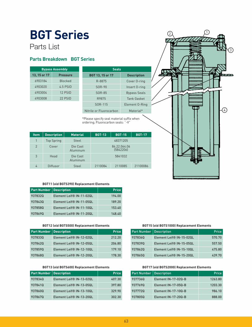
Parts Breakdown BGT Series
*Please specify seal material suffix when ordering; Fluorocarbon seals: “-V”
2 1
3
4
Seals
BGT 13, 15 or 17 Description
R-8875 Cover O-ring
SOR-90 Insert O-ring
SOR-85 Bypass Seals
R9875 Tank Gasket
SOR-115 Element O-Ring
Nitrile or Fluorocarbon Material*
Bypass Assembly
13, 15 or 17 Pressure
6903184 Blocked
4903020 4.5 PSID
4903004 12 PSID
4903008 22 PSID
Item Description Material BGT-13 BGT-15 BGT-17
1 Top Spring Steel 48371205
2 Cover Die CastAluminum
84.22.064.06 (5842206)
3 Head Die CastAluminum
5841032
4 Diffusor Steel 2110084 2110085 21100086
BGT11 (old BGTS390) Replacement Elements
Part Number Description Price
937832Q Element Leif® IN-11-02QL 194.00
937843Q Element Leif® IN-11-05QL 189.20
937858Q Element Leif® IN-11-10QL 153.40
937869Q Element Leif® IN-11-20QL 148.40
BGT12 (old BGTS500) Replacement Elements
Part Number Description Price
937833Q Element Leif® IN-12-02QL 212.20
937842Q Element Leif® IN-12-05QL 206.80
937859Q Element Leif® IN-12-10QL 179.10
937868Q Element Leif® IN-12-20QL 178.30
BGT13 (old BGTS600) Replacement Elements
Part Number Description Price
937834Q Element Leif® IN-13-02QL 407.30
937841Q Element Leif® IN-13-05QL 397.80
937860Q Element Leif® IN-13-10QL 329.90
937867Q Element Leif® IN-13-20QL 302.30
BGT15 (old BGTS1000) Replacement Elements
Part Number Description Price
937836Q Element Leif® IN-15-02QL 570.70
937839Q Element Leif® IN-15-05QL 557.50
937862Q Element Leif® IN-15-10QL 475.80
937865Q Element Leif® IN-15-20QL 439.70
BGT17 (old BGTS2000) Replacement Elements
Part Number Description Price
937736Q Element IN-17-02Q-B 1263.80
937769Q Element IN-17-05Q-B 1203.30
937772Q Element IN-17-10Q-B 986.10
937805Q Element IN-17-20Q-B 888.00
64
BGT Series
Operating And Maintenance Instructions Parker Model BGT Tank Top Filters
A. Mounting 1. Standard mounting. a. Cut proper size hole in the top
of the reservoir. b. Drill holes for studs within the
proper bolt circle. c. Set the filter into the cutout
hole and secure with proper size bolts, nuts and lock washers.
2. Utilize proper fittings.
B. Start-Up 1. Check for and eliminate leaks upon
system start-up. 2. Check differential pressure
indicator, if installed, to monitor element condition.
C. Service 1. An element must be serviced when
the indicator indicates service is required.
NOTE: If the filter is not equipped with an indicator, the element should be serviced according to machine manufacturer’s instructions.
D. Servicing Dirty Elements 1. Shut system down to assure that
there is NO PRESSURE OR FLOW into the filter housing.
2. Remove the filter cover. 3. Remove the filter insert (bridge
which holds the element in place).
4. Remove the bypass spring assembly or non-bypass plate from the stud.
5. Remove the contaminated cartridge with a twisting motion.
6. a. Discard the disposable element cartridge.
b. Wash cleanable or mesh elements in a non-caustic solvent. Compressed air can be used to facilitate cleaning. Use care to prevent damage to the element during cleaning.
NOTE: Elements finer than 150 microns (100 mesh) may require special ultrasonic cleaning. Consult factory for recommendations.
E. Before Installing A New Element Cartridge
1. Clean the magnetic core with a lint- free cloth.
2. Check all seals and replace if necessary.
F. To Install A New Or Cleaned Element Cartridge
1. Lubricate all seals. 2. Mount new or cleaned Parker
filter cartridge. NOTE: For ease of mounting, hold the
cartridge away from the magnetic core until the stud is through the hole in the bottom of the element. Then slide it up to securely seat it to the top of the bridge.
3. Install the bypass spring assembly or non-bypass plate, and tighten until snug.
NOTE: Older versions may have a cotter pin/castellated nut retained bypass spring. In these cases, the nut should be turned down the shaft until the cross drilled hole is visible in the base of a castellation and the cotter pin inserted and ends flared to lock the bypass assembly in place.
4. Re-install the insert into the filter housing, making sure that the top- spring is secure.
5. Re-install the cover. Torque the cover nuts to 22 ft./lbs.
Follow procedures B.1 and B.2.
65
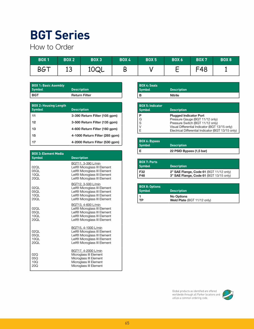
BGT SeriesHow to Order
BOX 1 BOX 2 BOX 3 BOX 4 BOX 5 BOX 6 BOX 7 BOX 8
BGT 13 10QL B V E F48 1
BOX 1: Basic Asembly Symbol
Description
BGT Return Filter
BOX 4: Seals Symbol
Description
B Nitrile
BOX 2: Housing Length Symbol
Description
11 3-390 Return Filter (105 gpm)
12 3-500 Return Filter (135 gpm)
13 4-600 Return Filter (160 gpm)
15 4-1000 Return Filter (265 gpm)
17 4-2000 Return Filter (530 gpm)
BOX 3: Element Media Symbol
Description
02QL05QL10QL20QL
BGT11, 3-390 L/min Leif® Microglass III ElementLeif® Microglass III ElementLeif® Microglass III ElementLeif® Microglass III Element
02QL05QL10QL20QL
BGT12, 3-500 L/minLeif® Microglass III Element Leif® Microglass III ElementLeif® Microglass III ElementLeif® Microglass III Element
02QL05QL10QL20QL
BGT13, 4-600 L/min Leif® Microglass III ElementLeif® Microglass III ElementLeif® Microglass III ElementLeif® Microglass III Element
02QL05QL10QL20QL
BGT15, 4-1000 L/minLeif® Microglass III Element Leif® Microglass III ElementLeif® Microglass III ElementLeif® Microglass III Element
02Q05Q10Q20Q
BGT17, 4-2000 L/minMicroglass III ElementMicroglass III ElementMicroglass III ElementMicroglass III Element
BOX 5: Indicator Symbol
Description
PGSVE
Plugged Indicator PortPressure Gauge (BGT 11/12 only)Pressure Switch (BGT 11/12 only)Visual Differential Indicator (BGT 13/15 only)Electrical Differential Indicator (BGT 13/15 only)
BOX 6: Bypass Symbol
Description
E 22 PSID Bypass (1,5 bar)
BOX 7: Ports Symbol
Description
F32F48
2” SAE Flange, Code 61 (BGT 11/12 only)3” SAE Flange, Code 61 (BGT 13/15 only)
BOX 8: Options Symbol
Description
1TP
No OptionsWeld Plate (BGT 11/12 only)
Global products as identified are offered worldwide through all Parker locations and utilize a common ordering code.


![Gila Bgt Nih Sertifikat]](https://img.pdfslide.net/doc/110x75/55cf8c515503462b138b605a/gila-bgt-nih-sertifikat.jpg)