Embed Size (px)
Citation preview
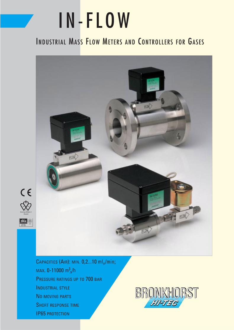
I N - F L O WINDUSTRIAL MASS FLOW METERS AND CONTROLLERS FOR GASES
CAPACITIES (AIR): MIN. 0,2...10 mln/min;
MAX. 0-11000 m3n/h
PRESSURE RATINGS UP TO 700 BAR
INDUSTRIAL STYLE
NO MOVING PARTS
SHORT RESPONSE TIME
IP65 PROTECTION
T H E A D V A N T A G E S A T A G L A N C E :The superiority of the IN-FLOW Mass Flow Meters and Controllers becomes clear as soon as you realize what you do not need:delta “p” measurement and piping, valves, pressure and temperature sensors. The compact instruments can easily be moun-ted in the pipeline, electrically connected and..…ready. New in this brochure are the instruments with digital “multibus” PC-boards with RS-232 or fieldbus interfaces.
IN T R O D U C T I O N
This brochure describes the IN-FLOW series; Mass Flow Meters and Controllers of rugged design (IP65) for use in pilot andproduction plants in industrial environments.
CO N T E N T S PA G E
Introduction and contents 2
Product range, quality and support 3
Measuring principle • Principle of operation 4
• Calibration and accuracy
IN-FLOW Mass Flow Meters for Gases • Fields of application 5 - 6
• Features
IN-FLOW Mass Flow Controllers for Gases • Control valves 7 - 8
Technical specifications • Calibration 9
Model number code • Enquiry and ordering information 10
LOW-∆P-FLOW Mass Flow Meters and Controllers • For low pressure drop applications 11
IN-FLOW digital • Specifications 12
• Software support
Readout Systems, digital 13
Readout Systems, analog 14
Other BRONKHORST HI-TEC products • EL-FLOW® 15
• EX-FLOW
• EL-PRESS
• LIQUI-FLOW®
IN T R O D U C T I O N A N D CO N T E N T S
2
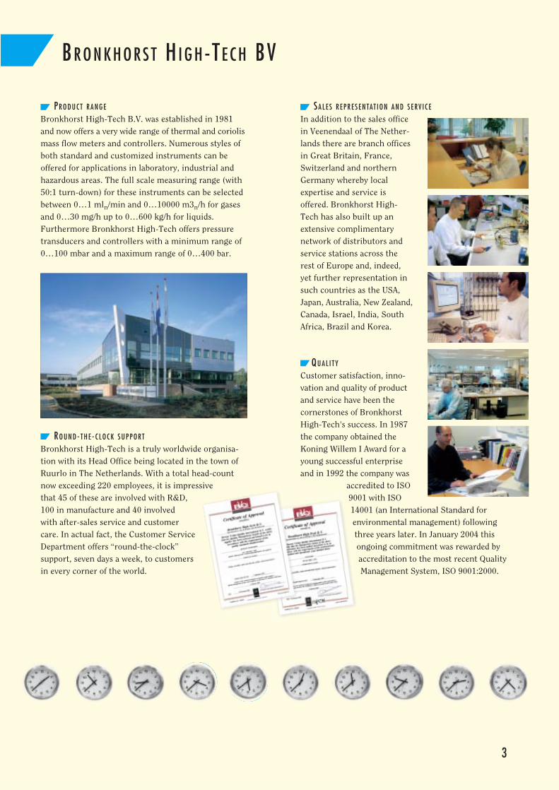
PR O D U C T R A N G E
Bronkhorst High-Tech B.V. was established in 1981and now offers a very wide range of thermal and coriolismass flow meters and controllers. Numerous styles ofboth standard and customized instruments can beoffered for applications in laboratory, industrial andhazardous areas. The full scale measuring range (with50:1 turn-down) for these instruments can be selectedbetween 0…1 mln/min and 0…10000 m3n/h for gasesand 0…30 mg/h up to 0…600 kg/h for liquids. Furthermore Bronkhorst High-Tech offers pressuretransducers and controllers with a minimum range of0…100 mbar and a maximum range of 0…400 bar.
RO U N D- T H E - C L O C K S U P P O RT
Bronkhorst High-Tech is a truly worldwide organisa-tion with its Head Office being located in the town ofRuurlo in The Netherlands. With a total head-countnow exceeding 220 employees, it is impressivethat 45 of these are involved with R&D,100 in manufacture and 40 involvedwith after-sales service and customercare. In actual fact, the Customer ServiceDepartment offers “round-the-clock” support, seven days a week, to customersin every corner of the world.
BR O N K H O R S T H I G H-TE C H BV
3
SA L E S R E P R E S E N TAT I O N A N D S E RV I C E
In addition to the sales officein Veenendaal of The Nether-lands there are branch officesin Great Britain, France,Switzerland and northernGermany whereby localexpertise and service isoffered. Bronkhorst High-Tech has also built up anextensive complimentarynetwork of distributors andservice stations across therest of Europe and, indeed,yet further representation insuch countries as the USA,Japan, Australia, New Zealand,Canada, Israel, India, SouthAfrica, Brazil and Korea.
QU A L I T Y
Customer satisfaction, inno-vation and quality of productand service have been thecornerstones of BronkhorstHigh-Tech's success. In 1987the company obtained theKoning Willem I Award for ayoung successful enterpriseand in 1992 the company was
accredited to ISO9001 with ISO14001 (an International Standard forenvironmental management) followingthree years later. In January 2004 thisongoing commitment was rewarded byaccreditation to the most recent QualityManagement System, ISO 9001:2000.
4
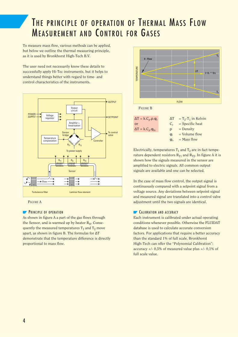
To measure mass flow, various methods can be applied,but below we outline the thermal measuring principle,as it is used by Bronkhorst High-Tech B.V.
The user need not necessarily know these details tosuccessfully apply Hi-Tec instruments, but it helps tounderstand things better with regard to time- and control characteristics of the instruments.
FIGURE A
PR I N C I P L E O F O P E R AT I O N
As shown in figure A a part of the gas flows throughthe Sensor, and is warmed up by heater RH. Conse-quently the measured temperatures T1 and T2 moveapart, as shown in figure B. The formulas for ∆Tdemonstrate that the temperature difference is directlyproportional to mass flow.
FIGURE B
∆T = k.Cp.ρ.φv ∆T = T2-T1 in Kelvinοr Cp = Specific heat∆T = k.Cp.φm ρ = Density
φv = Volume flowφm = Mass flow
Electrically, temperatures T1 and T2 are in fact tempe-rature dependent resistors RT1 and RT2. In figure A it isshown how the signals measured in the sensor areamplified to electric signals. All common output signals are available and one can be selected.
In the case of mass flow control, the output signal iscontinuously compared with a setpoint signal from avoltage source. Any deviations between setpoint signaland measured signal are translated into a control valveadjustment until the two signals are identical.
CA L I B R AT I O N A N D A C C U R A C Y
Each instrument is calibrated under actual operatingconditions whenever possible. Otherwise the FLUIDATdatabase is used to calculate accurate conversion factors. For applications that require a better accuracythan the standard 1% of full scale, Bronkhorst High-Tech can offer the “Polynomial Calibration”:accuracy +/- 0,5% of measured value plus +/- 0,1% offull scale value.
TH E P R I N C I P L E O F O P E R AT I O N O F TH E R M A L MA S S FL O WME A S U R E M E N T A N D CO N T R O L F O R GA S E S
TEM
PERA
TURE
FLOW
0 - Flow
ρ.φv = φm∆T
T1
T2
POWERSUPPLY
Outputcircuit
Amplifier +linearisation
Controller
RT2
Sensorbridge
To power supply
OUTPUT
SETPOINT
To controlvalve
Sensor
Temperaturecompensation
Voltageregulator
Laminar flow element
RT1
RT2RT1 RH
Flow
Turbulence filter
IN-FLOW MA S S FL O W ME T E R S F O R GA S E S U P T O PN700
5
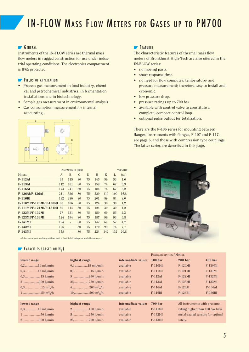
GE N E R A L
Instruments of the IN-FLOW series are thermal massflow meters in rugged construction for use under indus-trial operating conditions. The electronics compartmentis IP65 protected.
F I E L D S O F A P P L I C AT I O N
• Process gas measurement in food industry, chemi-cal and petrochemical industries, in fermentationinstallations and in biotechnology.
• Sample gas measurement in environmental analysis.• Gas consumption measurement for internal
accounting.
FE AT U R E S
The characteristic features of thermal mass flowmeters of Bronkhorst High-Tech are also offered in theIN-FLOW series:• no moving parts.• short response time.• no need for flow computer, temperature- and
pressure measurement; therefore easy to install andeconomic.
• low pressure drop.• pressure ratings up to 700 bar.• available with control valve to constitute a
complete, compact control loop.• optional pulse output for totalization.
There are the F-106 series for mounting between flanges, instruments with flanges, F-107 and F-117, see page 6, and those with compression type couplings.The latter series are described in this page.
CA PA C I T I E S (B A S E D O N N2)PRESSURE RATING / MODEL
lowest range highest range intermediate values 100 bar 200 bar 400 bar
0,2...............10 mln/min 0,3...............15 mln/min available F-110MI F-120MI F-130MI
0,3...............15 mln/min 0,3 ..................15 ln/min available F-111MI F-121MI F-131MI
0,3 ..................15 ln/min 5 ...................250 ln/min available F-112AI F-122MI F-132MI
2 ...................100 ln/min 25 ...............1250 ln/min available F-113AI F-123MI F-133MI
0,3...................15 m3n/h 4....................200 m3
n/h available F-116AI F-126AI F-136AI
1......................50 m3n/h 10..................500 m3
n/h available F-116BI F-126BI F-136BI
lowest range highest range intermediate values 700 bar All instruments with pressure
0,3...............15 mln/min 2 ...................100 ln/min available F-141MI rating higher than 100 bar have
1 .....................50 ln/min 5 ...................250 ln/min available F-142MI metal-sealed sensors for optimal
2 ...................100 ln/min 25 ...............1250 ln/min available F-143MI safety.
C
BA
H
K
L
D
DIMENSIONS (MM) WEIGHT
MODEL A B C D H K L (KG)
F-112AI 65 115 80 75 145 59 53 1,6
F-113AI 112 181 80 75 159 74 67 3,3
F-116AI 174 241 80 75 184 74 67 5,2
F-126AI/F-136AI 211 336 80 75 220 110 100 16,8
F-116BI 192 280 80 75 201 89 84 8,0
F-110MI/F-120MI/F-130MI 60 106 80 75 124 30 30 1,2
F-111MI/F-121MI/F-131MI 60 114 80 75 124 30 30 1,2
F-122MI/F-132MI 77 131 80 75 150 69 55 2,3
F-123MI/F-133MI 124 194 80 75 187 99 93 6,8
F-141MI 124 - 80 75 147 69 57 4,7
F-142MI 125 - 80 75 170 99 76 7,7
F-143MI 178 - 80 75 224 142 132 20,8
All data are subject to change without notice. Certified drawings are available on request.
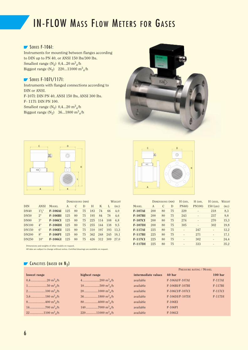
SE R I E S F -106I :Instruments for mounting between flanges accordingto DIN up to PN 40, or ANSI 150 lbs/300 lbs.Smallest range (N2) 0,4...20 m3
n/h Biggest range (N2) 220...11000 m3
n/h
SE R I E S F -107I/117I :Instruments with flanged connections according toDIN or ANSI.F-107I: DIN PN 40, ANSI 150 lbs, ANSI 300 lbs.F- 117I: DIN PN 100.Smallest range (N2) 0,4...20 m3
n/hBiggest range (N2) 36...1800 m3
n/h
CA PA C I T I E S (B A S E D O N N2)PRESSURE RATING / MODEL
lowest range highest range intermediate values 40 bar 100 bar
0,4...................20 m3n/h 4....................200 m3
n/h available F-106AI/F-107AI F-117AI
1......................50 m3n/h 10..................500 m3
n/h available F-106BI/F-107BI F-117BI
2....................100 m3n/h 20 ................1000 m3
n/h available F-106CI/F-107CI F-117CI
3,6 .................180 m3n/h 36 ................1800 m3
n/h available F-106DI/F-107DI F-117DI
8....................400 m3n/h 80 ................4000 m3
n/h available F-106EI
14..................700 m3n/h 140 ..............7000 m3
n/h available F-106FI
22 ................1100 m3n/h 220 ............11000 m3
n/h available F-106GI
6
IN-FLOW MA S S FL O W ME T E R S F O R GA S E S
C
A
H
D
DIMENSIONS (MM) WEIGHT
DIN ANSI MODEL A C D H K L (KG)
DN40 11⁄2" F-106AI 125 80 75 183 74 66 4,0
DN50 2" F-106BI 125 80 75 195 84 78 4,6
DN80 3" F-106CI 125 80 75 225 114 108 6,8
DN100 4" F-106DI 125 80 75 255 144 138 9,5
DN150 6" F-106EI 125 80 75 310 197 193 13,3
DN200 8" F-106FI 125 80 75 362 248 245 18,1
DN250 10" F-106GI 125 80 75 426 312 309 27,0
Dimensions and weights of other models on request.
All date are subject to change without notice. Certified drawings are available on request.
DIMENSIONS (MM) H (DIN, H (DIN, H (ANSI, WEIGHT
MODEL A C D PN40) PN100) 150 LBS) (KG)
F-107AI 200 80 75 229 - 218 8,3
F-107BI 200 80 75 243 - 237 9,8
F-107CI 200 80 75 274 - 270 15,3
F-107DI 200 80 75 305 - 302 19,8
F-117AI 225 80 75 - 247 - 12,2
F-117BI 225 80 75 - 271 - 17,1
F-117CI 225 80 75 - 302 - 24,4
F-117DI 225 80 75 - 333 - 35,2
A
C D
H
K
L
GE N E R A L
To convert a mass flow meter to a mass flow controllera control valve is added. The instruments of a F-112AIand F-113AI series can be furnished with a piped-oncontrol valve. The electronics housing of the mass flowmeter then contains a p.c. board with control functionto complete the control loop.
The instruments that start with the figure 2 in theirmodel code (e.g. F-203AI and F-216AI) are furnishedwith integrated control valve.
CO N T R O L VA LV E S
are available in various constructions such as
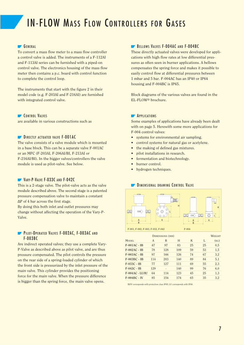
DI R E C T LY A C T U AT E D VA LV E F-001ACThe valve consists of a valve module which is mountedin a base block. This can be a separate valve F-001ACor an MFC (F-203AI, F-206AI/BI, F-213AI or F-216AI/BI). In the bigger valves/controllers the valvemodule is used as pilot-valve. See below.
VARY-P-VALVE F-033C AND F-042CThis is a 2-stage valve. The pilot-valve acts as the valvemodule described above. The second stage is a patentedpressure compensation valve to maintain a constant∆P of 4 bar across the first stage.By doing this both inlet and outlet pressures maychange without affecting the operation of the Vary-P-Valve.
PI L O T-OP E R AT E D VA LV E S F-002AC, F -003AC A N D
F-003BCAre indirect operated valves; they use a complete Vary-P-Valve as described above as pilot valve, and are thuspressure compensated. The pilot controls the pressureon the rear side of a spring-loaded cylinder of whichthe front side is pressurized by the inlet pressure of themain valve. This cylinder provides the positioningforce for the main valve. When the pressure differenceis bigger than the spring force, the main valve opens.
BE L L O W S VA LV E S F-004AC A N D F-004BCThese directly actuated valves were developed for appli-cations with high flow rates at low differential pres-sures as often seen in burner applications. A bellowscompensates the spring force and makes it possible toeasily control flow at differential pressures between 1 mbar and 5 bar. F-004AC has an IP40 or IP64housing and F-004BC is IP65.
Block diagrams of the various valves are found in theEL-FLOW® brochure.
AP P L I C AT I O N S
Some examples of applications have already been dealtwith on page 5. Herewith some more applications forF-004 control valves:• systems for environmental air sampling.• control systems for natural gas or acetylene.• the making of defined gas mixtures.• pilot installations in research.• fermentation and biotechnology.• burner control.• hydrogen techniques.
DI M E N S I O N A L D R AW I N G CO N T R O L VA LV E
7
IN-FLOW MA S S FL O W CO N T R O L L E R S F O R GA S E S
DIMENSIONS (MM) WEIGHT
MODEL A B H K L (KG)
F-001AC - IB 47 97 83 25 25 0,5
F-002AC - IB 78 128 109 59 53 1,5
F-003AC - IB 97 166 126 74 67 3,2
F-003BC - IB 114 203 140 89 84 5,1
F-033C - IB 77 127 111 69 55 2,3
F-042C - IB 129 - 140 99 76 6,0
F-004AC - LU/IU 64 114 123 45 25 1,3
F-004BC - IV 85 154 174 65 35 3,2
IB/IV corresponds with protection class IP65; LU corresponds with IP40.
H
K
L
BA K
L
H
BA
F-001, F-002, F-003, F-033, F-042 F-004
8
FL O W C A PA C I T I E S (B A S E D O N N2)MFM + Valve smallest biggest
F-111MI/F-001AC 0,3 ....15 mln/min 0,3 .......15 ln/min
F-112AI/F-001AC 0,3 .......15 ln/min 2,0 .....100 ln/min
F-112AI/F-002AC 0,1 .........5 ln/min 5 ........250 ln/min
MFC with integrated valve
F-203AI/F-213AI 1 ..........50 ln/min 25 ....1250 ln/min
F-206AI/F-216AI 0,4........20 m3n/h 4.........200 m3
n/h
F-206BI/F-216BI 1...........50 m3n/h 10.......500 m3
n/h
MFC for high-pressure applications (PN400/PN700)
F-230MI/F-240MI 0,2....10 mln/min 10...500 mln/min
F-231MI/F-241MI 10...500 mln/min 0,2 .......10 ln/min
F-232MI/F-242MI 0,2 .......10 ln/min 2 ........100 ln/min
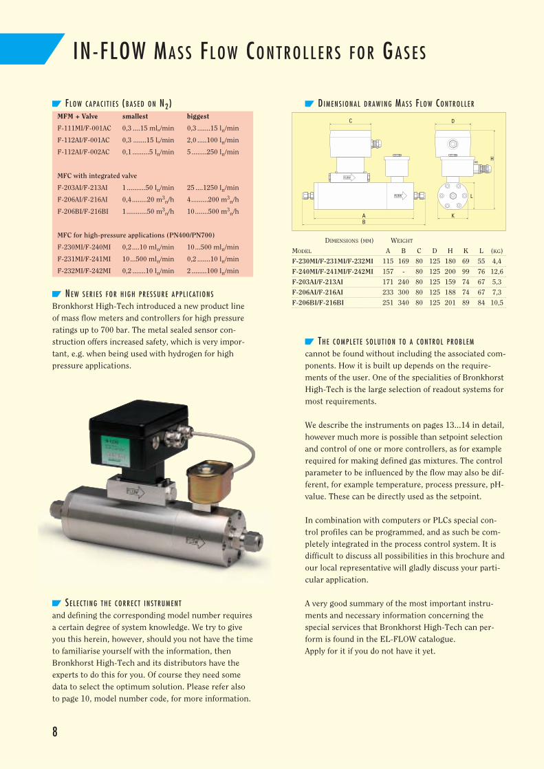
NE W S E R I E S F O R H I G H P R E S S U R E A P P L I C AT I O N S
Bronkhorst High-Tech introduced a new product lineof mass flow meters and controllers for high pressureratings up to 700 bar. The metal sealed sensor con-struction offers increased safety, which is very impor-tant, e.g. when being used with hydrogen for highpressure applications.
SE L E C T I N G T H E C O R R E C T I N S T R U M E N T
and defining the corresponding model number requiresa certain degree of system knowledge. We try to giveyou this herein, however, should you not have the timeto familiarise yourself with the information, thenBronkhorst High-Tech and its distributors have theexperts to do this for you. Of course they need somedata to select the optimum solution. Please refer alsoto page 10, model number code, for more information.
DI M E N S I O N A L D R AW I N G MA S S FL O W CO N T R O L L E R
TH E C O M P L E T E S O L U T I O N T O A C O N T R O L P R O B L E M
cannot be found without including the associated com-ponents. How it is built up depends on the require-ments of the user. One of the specialities of BronkhorstHigh-Tech is the large selection of readout systems formost requirements.
We describe the instruments on pages 13...14 in detail,however much more is possible than setpoint selectionand control of one or more controllers, as for examplerequired for making defined gas mixtures. The controlparameter to be influenced by the flow may also be dif-ferent, for example temperature, process pressure, pH-value. These can be directly used as the setpoint.
In combination with computers or PLCs special con-trol profiles can be programmed, and as such be com-pletely integrated in the process control system. It isdifficult to discuss all possibilities in this brochure andour local representative will gladly discuss your parti-cular application.
A very good summary of the most important instru-ments and necessary information concerning the special services that Bronkhorst High-Tech can per-form is found in the EL-FLOW catalogue. Apply for it if you do not have it yet.
IN-FLOW MA S S FL O W CO N T R O L L E R S F O R GA S E S
D
H
K
L
BA
C
DIMENSIONS (MM) WEIGHT
MODEL A B C D H K L (KG)
F-230MI/F-231MI/F-232MI 115 169 80 125 180 69 55 4,4
F-240MI/F-241MI/F-242MI 157 - 80 125 200 99 76 12,6
F-203AI/F-213AI 171 240 80 125 159 74 67 5,3
F-206AI/F-216AI 233 300 80 125 188 74 67 7,3
F-206BI/F-216BI 251 340 80 125 201 89 84 10,5
9
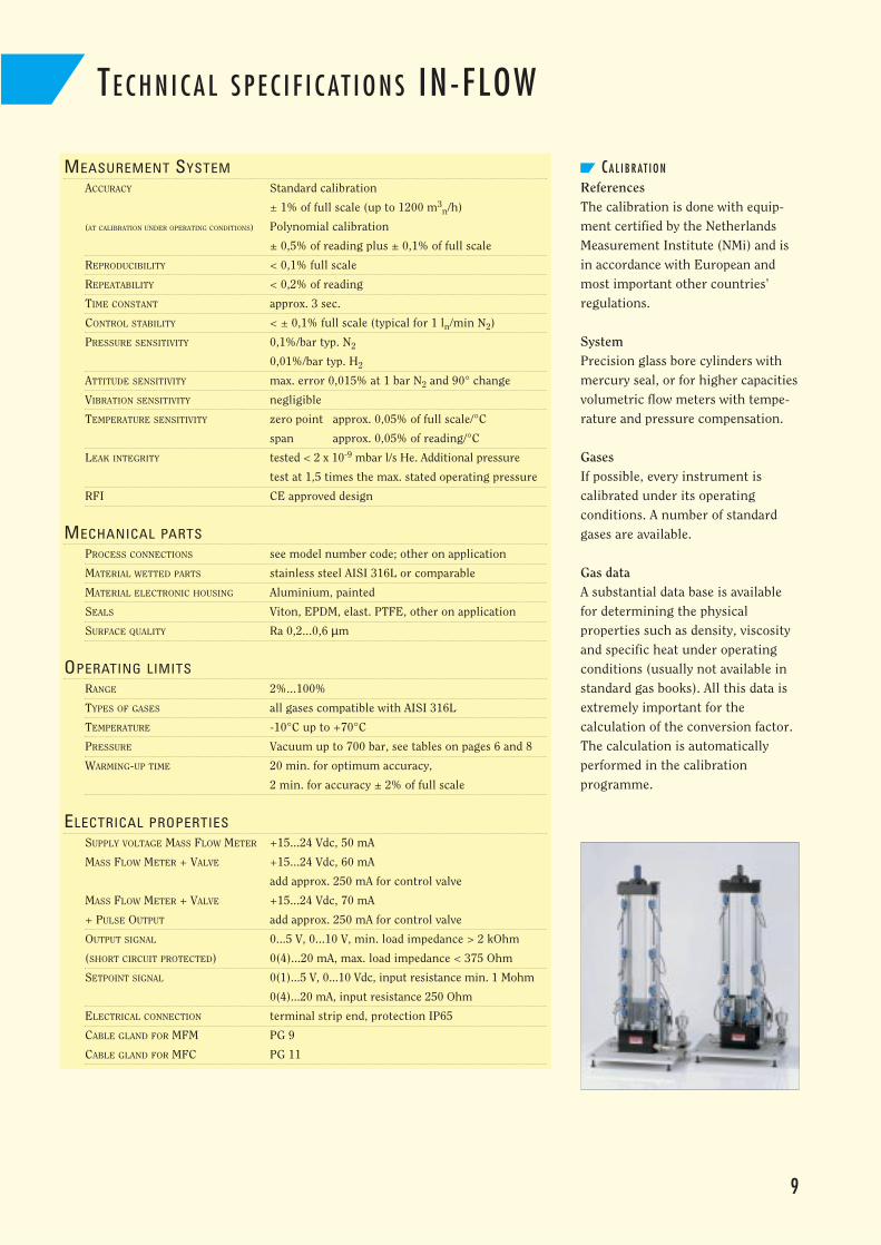
CA L I B R AT I O N
ReferencesThe calibration is done with equip-ment certified by the NetherlandsMeasurement Institute (NMi) and isin accordance with European andmost important other countries’regulations.
SystemPrecision glass bore cylinders withmercury seal, or for higher capacitiesvolumetric flow meters with tempe-rature and pressure compensation.
GasesIf possible, every instrument is calibrated under its operating conditions. A number of standardgases are available.
Gas dataA substantial data base is availablefor determining the physical properties such as density, viscosityand specific heat under operatingconditions (usually not available instandard gas books). All this data isextremely important for the calculation of the conversion factor.The calculation is automatically performed in the calibration programme.
TE C H N I C A L S P E C I F I C AT I O N S IN-FLOW
MEASUREMENT SYSTEMACCURACY Standard calibration
± 1% of full scale (up to 1200 m3n/h)
(AT CALIBRATION UNDER OPERATING CONDITIONS) Polynomial calibration
± 0,5% of reading plus ± 0,1% of full scale
REPRODUCIBILITY < 0,1% full scale
REPEATABILITY < 0,2% of reading
TIME CONSTANT approx. 3 sec.
CONTROL STABILITY < ± 0,1% full scale (typical for 1 ln/min N2)
PRESSURE SENSITIVITY 0,1%/bar typ. N2
0,01%/bar typ. H2
ATTITUDE SENSITIVITY max. error 0,015% at 1 bar N2 and 90° change
VIBRATION SENSITIVITY negligible
TEMPERATURE SENSITIVITY zero point approx. 0,05% of full scale/°C
span approx. 0,05% of reading/°C
LEAK INTEGRITY tested < 2 x 10⁻⁹ mbar l/s He. Additional pressure
test at 1,5 times the max. stated operating pressure
RFI CE approved design
MECHANICAL PARTSPROCESS CONNECTIONS see model number code; other on application
MATERIAL WETTED PARTS stainless steel AISI 316L or comparable
MATERIAL ELECTRONIC HOUSING Aluminium, painted
SEALS Viton, EPDM, elast. PTFE, other on application
SURFACE QUALITY Ra 0,2...0,6 µm
OPERATING LIMITSRANGE 2%...100%
TYPES OF GASES all gases compatible with AISI 316L
TEMPERATURE -10°C up to +70°C
PRESSURE Vacuum up to 700 bar, see tables on pages 6 and 8
WARMING-UP TIME 20 min. for optimum accuracy,
2 min. for accuracy ± 2% of full scale
ELECTRICAL PROPERTIESSUPPLY VOLTAGE MASS FLOW METER +15...24 Vdc, 50 mA
MASS FLOW METER + VALVE +15...24 Vdc, 60 mA
add approx. 250 mA for control valve
MASS FLOW METER + VALVE +15...24 Vdc, 70 mA
+ PULSE OUTPUT add approx. 250 mA for control valve
OUTPUT SIGNAL 0...5 V, 0...10 V, min. load impedance > 2 kOhm
(SHORT CIRCUIT PROTECTED) 0(4)...20 mA, max. load impedance < 375 Ohm
SETPOINT SIGNAL 0(1)...5 V, 0...10 Vdc, input resistance min. 1 Mohm
0(4)...20 mA, input resistance 250 Ohm
ELECTRICAL CONNECTION terminal strip end, protection IP65
CABLE GLAND FOR MFM PG 9
CABLE GLAND FOR MFC PG 11
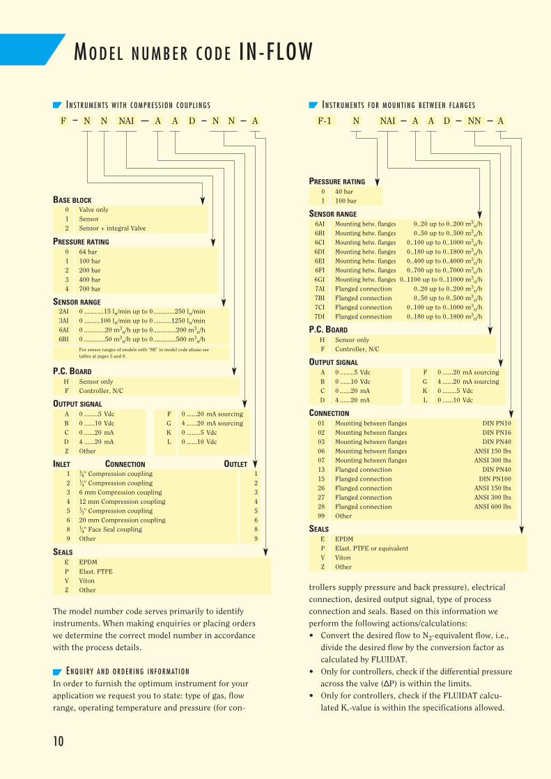
IN S T R U M E N T S F O R M O U N T I N G B E T W E E N F L A N G E SIN S T R U M E N T S W I T H C O M P R E S S I O N C O U P L I N G S
NNF-1NAI
1 1⁄8" Compression coupling 12 1⁄4" Compression coupling 23 6 mm Compression coupling 34 12 mm Compression coupling 45 1⁄2" Compression coupling 56 20 mm Compression coupling 68 1⁄4" Face Seal coupling 89 Other 9
10
0 64 bar1 100 bar2 200 bar3 400 bar4 700 bar
2AI 0 ...........15 ln/min up to 0 ............250 ln/min3AI 0 .........100 ln/min up to 0 ..........1250 ln/min6AI 0 ............20 m3
n/h up to 0.............200 m3n/h
6BI 0 ............50 m3n/h up to 0.............500 m3
n/h
For sensor ranges of models with “MI” in model code please seetables at pages 5 and 8.
PRESSURE RATING
SENSOR RANGE
H Sensor onlyF Controller, N/C
P.C. BOARD
A 0 ........5 Vdc F 0 ......20 mA sourcingB 0 ......10 Vdc G 4 ......20 mA sourcingC 0 ......20 mA K 0 ........5 VdcD 4 ......20 mA L 0 ......10 VdcZ Other
OUTPUT SIGNAL
H Sensor onlyF Controller, N/C
P.C. BOARD
A 0 ........5 Vdc F 0 ......20 mA sourcingB 0 ......10 Vdc G 4 ......20 mA sourcingC 0 ......20 mA K 0 ........5 VdcD 4 ......20 mA L 0 ......10 Vdc
OUTPUT SIGNAL
E EPDMP Elast. PTFEV VitonZ Other
INLET CONNECTION OUTLET
SEALS
0 Valve only1 Sensor2 Sensor + integral Valve
F N NN N N AA A A ANAI
01 Mounting between flanges DIN PN1002 Mounting between flanges DIN PN1603 Mounting between flanges DIN PN4006 Mounting between flanges ANSI 150 lbs07 Mounting between flanges ANSI 300 lbs13 Flanged connection DIN PN4015 Flanged connection DIN PN10026 Flanged connection ANSI 150 lbs27 Flanged connection ANSI 300 lbs28 Flanged connection ANSI 600 lbs99 Other
E EPDMP Elast. PTFE or equivalentV VitonZ Other
CONNECTION
PRESSURE RATING
SEALS
6AI Mounting betw. flanges 0..20 up to 0..200 m3n/h
6BI Mounting betw. flanges 0..50 up to 0..500 m3n/h
6CI Mounting betw. flanges 0..100 up to 0..1000 m3n/h
6DI Mounting betw. flanges 0..180 up to 0..1800 m3n/h
6EI Mounting betw. flanges 0..400 up to 0..4000 m3n/h
6FI Mounting betw. flanges 0..700 up to 0..7000 m3n/h
6GI Mounting betw. flanges 0..1100 up to 0..11000 m3n/h
7AI Flanged connection 0..20 up to 0..200 m3n/h
7BI Flanged connection 0..50 up to 0..500 m3n/h
7CI Flanged connection 0..100 up to 0..1000 m3n/h
7DI Flanged connection 0..180 up to 0..1800 m3n/h
0 40 bar1 100 bar
A
MO D E L N U M B E R C O D E IN-FLOW
The model number code serves primarily to identifyinstruments. When making enquiries or placing orderswe determine the correct model number in accordancewith the process details.
EN Q U I RY A N D O R D E R I N G I N F O R M AT I O N
In order to furnish the optimum instrument for yourapplication we request you to state: type of gas, flowrange, operating temperature and pressure (for con-
trollers supply pressure and back pressure), electricalconnection, desired output signal, type of process connection and seals. Based on this information weperform the following actions/calculations:• Convert the desired flow to N2-equivalent flow, i.e.,
divide the desired flow by the conversion factor ascalculated by FLUIDAT.
• Only for controllers, check if the differential pressureacross the valve (∆P) is within the limits.
• Only for controllers, check if the FLUIDAT calcu-lated Kv-value is within the specifications allowed.
BASE BLOCK
SENSOR RANGE
D D
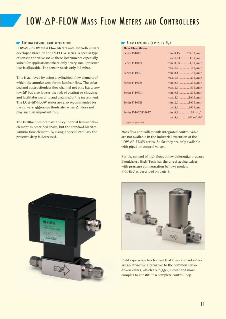
LOW-∆P-FLOW MA S S FL O W ME T E R S A N D CO N T R O L L E R S
11
FOR LOW PRESSURE DROP APPLICATIONS
LOW-∆P-FLOW Mass Flow Meters and Controllers weredeveloped based on the IN-FLOW series. A special typeof sensor and valve make these instruments especiallysuited for applications where only a very small pressureloss is allowable. The sensor needs only 0,2 mbar.
This is achieved by using a cylindrical flow element ofwhich the annular area forms laminar flow. The enlar-ged and obstructionless flow channel not only has a verylow ∆P but also lowers the risk of coating or cloggingand facilitates purging and cleaning of the instrument.The LOW-∆P-FLOW series are also recommended foruse on very aggressive fluids also when ∆P does notplay such an important role.
The F-106Z does not have the cylindrical laminar flowelement as described above, but the standard Meriamlaminar flow element. By using a special capillary thepressure drop is decreased.
FL O W C A PA C I T I E S (B A S E S O N N2)Mass Flow Meters
Series F-101DI min. 0,15 .........7,5 mln/min
max. 0,03 ............1,5 ln/min
Series F-101EI min. 0,03 ............1,5 ln/min
max. 0,2 ...............10 ln/min
Series F-102DI min. 0,1 .................5 ln/min
max. 0,6 ...............30 ln/min
Series F-102EI min. 0,6 ...............30 ln/min
max. 1,0 ...............50 ln/min
Series F-103DI min. 0,4 ...............20 ln/min
max. 2,0 .............100 ln/min
Series F-103EI min. 2,0 .............100 ln/min
max. 4,0 .............200 ln/min
Series F-106Z/F-107Z min. 0,2................10 m3n/h
max. 4,0............200 m3n/h*
*) higher on application
Mass flow controllers with integrated control valve are not available in the industrial execution of theLOW-∆P-FLOW series. So far they are only availablewith piped-on control valves.
For the control of high flows at low differential pressureBronkhorst High-Tech has the direct acting valveswith pressure compensation bellows models F-004BC as described on page 7.
Field experience has learned that these control valvesare an attractive alternative to the common servo-driven valves, which are bigger, slower and more complex to constitute a complete control loop.
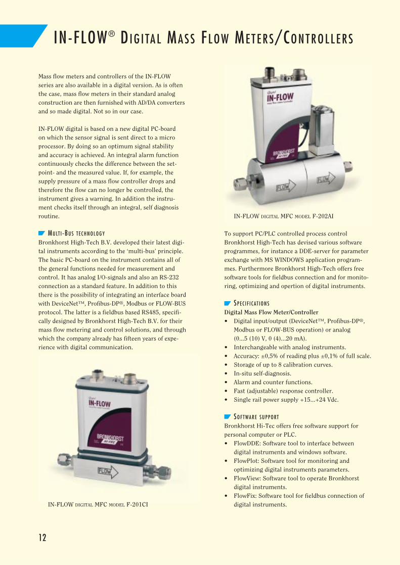
IN-FLOW ® DI G I TA L MA S S FL O W ME T E R S/CO N T R O L L E R S
Mass flow meters and controllers of the IN-FLOWseries are also available in a digital version. As is oftenthe case, mass flow meters in their standard analogconstruction are then furnished with AD/DA convertersand so made digital. Not so in our case.
IN-FLOW digital is based on a new digital PC-board on which the sensor signal is sent direct to a microprocessor. By doing so an optimum signal stability and accuracy is achieved. An integral alarm functioncontinuously checks the difference between the set-point- and the measured value. If, for example, thesupply pressure of a mass flow controller drops andtherefore the flow can no longer be controlled, the instrument gives a warning. In addition the instru-ment checks itself through an integral, self diagnosisroutine.
MU LT I -BU S T E C H N O L O G Y
Bronkhorst High-Tech B.V. developed their latest digi-tal instruments according to the ‘multi-bus’ principle.The basic PC-board on the instrument contains all ofthe general functions needed for measurement andcontrol. It has analog I/O-signals and also an RS-232connection as a standard feature. In addition to thisthere is the possibility of integrating an interface boardwith DeviceNet™, Profibus-DP®, Modbus or FLOW-BUSprotocol. The latter is a fieldbus based RS485, specifi-cally designed by Bronkhorst High-Tech B.V. for theirmass flow metering and control solutions, and throughwhich the company already has fifteen years of expe-rience with digital communication.
To support PC/PLC controlled process control Bronkhorst High-Tech has devised various softwareprogrammes, for instance a DDE-server for parameterexchange with MS WINDOWS application program-mes. Furthermore Bronkhorst High-Tech offers freesoftware tools for fieldbus connection and for monito-ring, optimizing and opertion of digital instruments.
SP E C I F I C AT I O N S
Digital Mass Flow Meter/Controller• Digital input/output (DeviceNet™, Profibus-DP®,
Modbus or FLOW-BUS operation) or analog (0...5 (10) V, 0 (4)...20 mA).
• Interchangeable with analog instruments.• Accuracy: ±0,5% of reading plus ±0,1% of full scale.• Storage of up to 8 calibration curves.• In-situ self-diagnosis.• Alarm and counter functions.• Fast (adjustable) response controller.• Single rail power supply +15...+24 Vdc.
SO F T WA R E S U P P O RT
Bronkhorst Hi-Tec offers free software support for personal computer or PLC.• FlowDDE: Software tool to interface between
digital instruments and windows software.• FlowPlot: Software tool for monitoring and
optimizing digital instruments parameters.• FlowView: Software tool to operate Bronkhorst
digital instruments.• FlowFix: Software tool for fieldbus connection of
digital instruments.
12
IN-FLOW DIGITAL MFC MODEL F-202AI
IN-FLOW DIGITAL MFC MODEL F-201CI
RE A D O U T SY S T E M S W I T H IN T E G R AT E D PO W E R SU P P LY
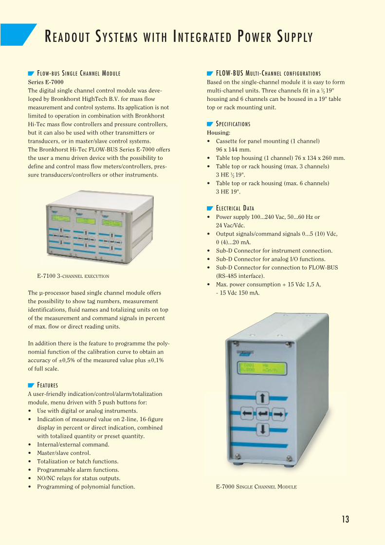
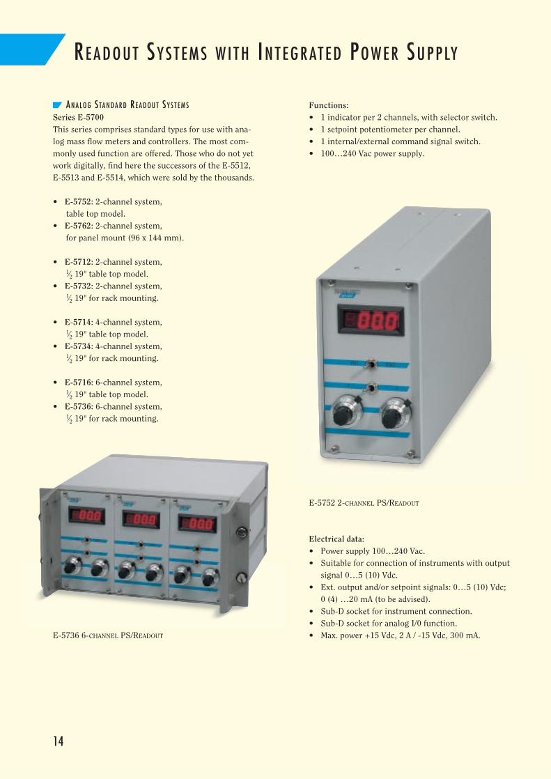
FL O W-B U S S I N G L E CH A N N E L MO D U L E
Series E-7000The digital single channel control module was deve-loped by Bronkhorst HighTech B.V. for mass flow measurement and control systems. Its application is notlimited to operation in combination with BronkhorstHi-Tec mass flow controllers and pressure controllers,but it can also be used with other transmitters ortransducers, or in master/slave control systems.The Bronkhorst Hi-Tec FLOW-BUS Series E-7000 offersthe user a menu driven device with the possibility todefine and control mass flow meters/controllers, pres-sure transducers/controllers or other instruments.
The µ-processor based single channel module offersthe possibility to show tag numbers, measurementidentifications, fluid names and totalizing units on topof the measurement and command signals in percentof max. flow or direct reading units.
In addition there is the feature to programme the poly-nomial function of the calibration curve to obtain anaccuracy of ±0,5% of the measured value plus ±0,1%of full scale.
FE AT U R E S
A user-friendly indication/control/alarm/totalizationmodule, menu driven with 5 push buttons for:• Use with digital or analog instruments.• Indication of measured value on 2-line, 16-figure
display in percent or direct indication, combinedwith totalized quantity or preset quantity.
• Internal/external command.• Master/slave control.• Totalization or batch functions.• Programmable alarm functions.• NO/NC relays for status outputs.• Programming of polynomial function.
FLOW-BUS MU LT I -CH A N N E L C O N F I G U R AT I O N S
Based on the single-channel module it is easy to formmulti-channel units. Three channels fit in a 1⁄2 19" housing and 6 channels can be housed in a 19" tabletop or rack mounting unit.
SP E C I F I C AT I O N S
Housing:• Cassette for panel mounting (1 channel)
96 x 144 mm.• Table top housing (1 channel) 76 x 134 x 260 mm.• Table top or rack housing (max. 3 channels)
3 HE 1⁄2 19".• Table top or rack housing (max. 6 channels)
3 HE 19".
EL E C T R I C A L DATA
• Power supply 100...240 Vac, 50...60 Hz or 24 Vac/Vdc.
• Output signals/command signals 0...5 (10) Vdc, 0 (4)...20 mA.
• Sub-D Connector for instrument connection.• Sub-D Connector for analog I/O functions.• Sub-D Connector for connection to FLOW-BUS
(RS-485 interface).• Max. power consumption + 15 Vdc 1,5 A,
- 15 Vdc 150 mA.
13
E-7100 3-CHANNEL EXECUTION
E-7000 SINGLE CHANNEL MODULE
14
RE A D O U T SY S T E M S W I T H IN T E G R AT E D PO W E R SU P P LY
AN A L O G STA N D A R D RE A D O U T SY S T E M S
Series E-5700This series comprises standard types for use with ana-log mass flow meters and controllers. The most com-monly used function are offered. Those who do not yetwork digitally, find here the successors of the E-5512,E-5513 and E-5514, which were sold by the thousands.
• E-5752: 2-channel system,table top model.
• E-5762: 2-channel system,for panel mount (96 x 144 mm).
• E-5712: 2-channel system,1⁄2 19" table top model.
• E-5732: 2-channel system,1⁄2 19" for rack mounting.
• E-5714: 4-channel system,1⁄2 19" table top model.
• E-5734: 4-channel system,1⁄2 19" for rack mounting.
• E-5716: 6-channel system,1⁄2 19" table top model.
• E-5736: 6-channel system,1⁄2 19" for rack mounting.
E-5736 6-CHANNEL PS/READOUT
Functions:• 1 indicator per 2 channels, with selector switch.• 1 setpoint potentiometer per channel.• 1 internal/external command signal switch.• 100…240 Vac power supply.
E-5752 2-CHANNEL PS/READOUT
Electrical data:• Power supply 100…240 Vac.• Suitable for connection of instruments with output
signal 0…5 (10) Vdc.• Ext. output and/or setpoint signals: 0…5 (10) Vdc;
0 (4) …20 mA (to be advised).• Sub-D socket for instrument connection.• Sub-D socket for analog I/0 function.• Max. power +15 Vdc, 2 A / -15 Vdc, 300 mA.
15
OT H E R BRONKHORST HI -TEC PR O D U C T S
In addition to the instruments of the IN-FLOW series described in this catalogue we would like to identify some other product groups within our range of instruments and their corresponding brochures.
If one or more instruments described here are of interest to you, then please do not hesitate to contact your distributor.
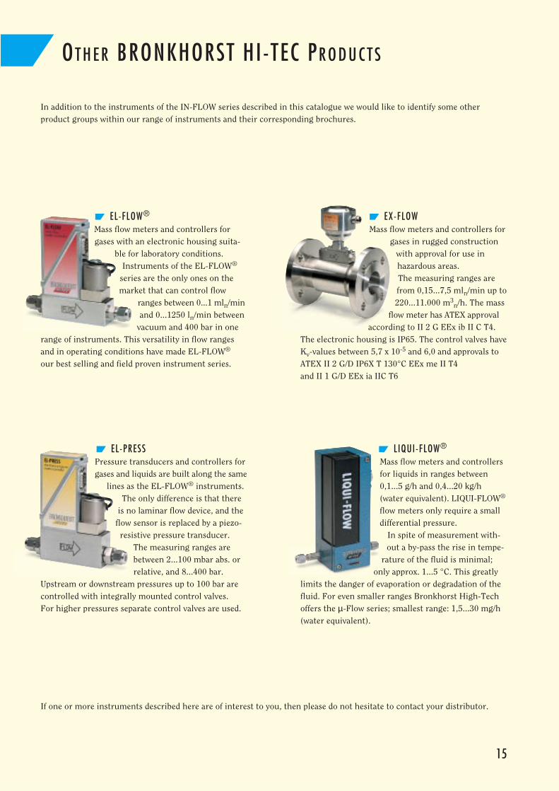
EX-FLOWMass flow meters and controllers for
gases in rugged constructionwith approval for use inhazardous areas. The measuring ranges arefrom 0,15...7,5 mln/min up to220...11.000 m3
n/h. The massflow meter has ATEX approval
according to II 2 G EEx ib II C T4.The electronic housing is IP65. The control valves haveKv-values between 5,7 x 10⁻⁵ and 6,0 and approvals toATEX II 2 G/D IP6X T 130°C EEx me II T4 and II 1 G/D EEx ia IIC T6
EL-FLOW®
Mass flow meters and controllers forgases with an electronic housing suita-
ble for laboratory conditions. Instruments of the EL-FLOW®
series are the only ones on themarket that can control flow
ranges between 0...1 mln/minand 0...1250 ln/min between
vacuum and 400 bar in onerange of instruments. This versatility in flow rangesand in operating conditions have made EL-FLOW®
our best selling and field proven instrument series.
LIQUI-FLOW®
Mass flow meters and controllersfor liquids in ranges between0,1...5 g/h and 0,4...20 kg/h (water equivalent). LIQUI-FLOW®
flow meters only require a smalldifferential pressure.
In spite of measurement with-out a by-pass the rise in tempe-
rature of the fluid is minimal;only approx. 1...5 °C. This greatly
limits the danger of evaporation or degradation of thefluid. For even smaller ranges Bronkhorst High-Techoffers the µ-Flow series; smallest range: 1,5...30 mg/h(water equivalent).
EL-PRESSPressure transducers and controllers forgases and liquids are built along the same
lines as the EL-FLOW® instruments.The only difference is that there
is no laminar flow device, and theflow sensor is replaced by a piezo-resistive pressure transducer.
The measuring ranges arebetween 2...100 mbar abs. orrelative, and 8...400 bar.
Upstream or downstream pressures up to 100 bar arecontrolled with integrally mounted control valves. For higher pressures separate control valves are used.