Embed Size (px)
Citation preview

ENGLISH
BI-FIRE MID Pellet and Wood boiler stove INSTALLATION, USE AND MAINTENANCE, USEFUL TIPS


SERVICE DECLARATION Ref. Annex III EU Regulation no. 305/2011
DoP/KLOVER-021 1. Identification number : BFM 2. Model and/or lot no. and/or serial no. (Art.11-4) : BI-FIRE MID
3. Intended use of the product according to the relevant harmonised technical specification
: Home heating appliance fed with wood pellets and wood logs which can also produce domestic hot water
4. Name or trademark of the manufacturer (Art11-5) : KLOVER s.r.l. I - 37047 San Bonifacio (VR) – Via A. Volta, 8
5. Name and address of the representative (Art.12-2) : - 6. Assessment and verification system of the
performance constancy (Annex 5) : System 3
7. Notified laboratory :
NB 1881 IMQprimacontrol s.r.l. I – 31020 Zoppè di San Vendemiano (TV) Via dell’Industria, 55
Number of test report (based on System 3) : CS-10-047, CS-10-048
8. Declared performances
HARMONISED TECHNICAL SPECIFICATION EN 14785 EN 13240
PERFORMANCE FEATURES PERFORMANCE PERFORMANCE
Fire resistance A1 A1
Distance from combustible material 200 mm 200 mm
Fuel spillage risk Compliant Compliant
Emission of combustion products - Nominal power - Reduced power
CO at 13% of O2 0,025 %
CO at 13% of O2 0,043 % CO at 13% of O2 0,016 %
Effective temperature Compliant Compliant
Electrical safety Compliant Compliant
Accessibility and cleaning Compliant Compliant
Maximum operating pressure 2,5 bar 2,5 bar
Mechanical strength NPD (performance not determined)
NPD (performance not determined)
Thermal performance - Nominal power (reduced) - Nominal power (reduced) yielded to the environment - Nominal power (reduced) yielded to water
15 kW (4,9 kW)
4,3 kW (1,9 kW) 10,7 kW (3 kW)
12,7 kW 3 kW
9,7 kW
Yield - Nominal power - Reduced power
ɳ 90,8 %
ɳ 90,7 % ɳ 76,3 %
Flue gas temperature - Nominal power - Reduced power
T 127 °C
T 72 °C T 161 °C
9. The performance of the product referred to in points 1 and 2 is compliant with the declared performance in point 8.
This declaration is released on the sole responsibility of the manufacturer referred to in point 4.
Signed in the name and on behalf of the manufacturer by:
San Bonifacio (VR), 24/08/2015
Mario Muraro Chairman of the Board

CONTENTS
CONTENTS ........................................................................................................................................................................ 3
INTRODUCTION ................................................................................................................................................................. 1
IMPORTANT SECURITY INSTRUCTIONS ............................................................................................................................... 1 SOME PRECAUTIONS ........................................................................................................................................................ 1 DESTINATION OF USE ....................................................................................................................................................... 1 INSTALLATION REGULATIONS ............................................................................................................................................ 2 HEALTH AND SAFETY ........................................................................................................................................................ 2
THE THERMO STOVE, THE PELLETS AND WOOD ........................................................................................................ 2
THERMO STOVE COMPONENTS ......................................................................................................................................... 2 CLEARANCE ..................................................................................................................................................................... 5 CONNECTIONS DATA SHEET .............................................................................................................................................. 6 TECHNICAL FEATURES ...................................................................................................................................................... 7 PELLET FEATURES............................................................................................................................................................ 7 WOOD FEATURES ............................................................................................................................................................. 8
REQUIREMENTS OF THE PLACE OF INSTALLATION ................................................................................................... 9
POSITIONING .................................................................................................................................................................... 9 SPACES AROUND AND ABOVE THE THERMO STOVE ............................................................................................................. 9 EXTERNAL AIR VENT ......................................................................................................................................................... 9 FLUE AND CONNECTION TO THE SAME ............................................................................................................................. 10 CHIMNEY ....................................................................................................................................................................... 11
CONNECTIONS ................................................................................................................................................................ 12
ELECTRICAL CONNECTION .............................................................................................................................................. 12 CONTROL OF ANY COUPLED BOILER ................................................................................................................................ 12 CONTROL OF ANY 3-WAY VALVE FOR THE DHW CIRCUIT .................................................................................................. 13 HYDRAULIC CONNECTION ............................................................................................................................................... 14
COMMISSIONING ............................................................................................................................................................ 14
FILLING THE SYSTEM FOR THE FIRST TIME........................................................................................................................ 14 PELLET LOADING AND CONNECTION TO THE ELECTRIC NETWORK ...................................................................................... 15 THERMO STOVE CONTROL PANEL .................................................................................................................................... 15 THE BUTTONS ................................................................................................................................................................ 16 THE LEDS ..................................................................................................................................................................... 16 DISPLAY DURING THE WORK PHASE ................................................................................................................................. 17 FUNCTIONING PRINCIPLE ................................................................................................................................................ 17 IGNITION OF THE THERMO STOVE (WOOD SIDE) ............................................................................................................ 18 BOILING ......................................................................................................................................................................... 19 IGNITION OF THE THERMO STOVE (PELLET SIDE) ........................................................................................................... 19 THERMO STOVE WORKING MODE (PELLET SIDE) ........................................................................................................... 20 SWITCH-OFF OF THE THERMO STOVE (PELLET SIDE) ..................................................................................................... 20 MODIFYING SET TEMPERATURE ....................................................................................................................................... 21 PRODUCING DOMESTIC HOT WATER (PREPARED MODELS ONLY) ....................................................................................... 21 CHRONO-THERMOSTAT .................................................................................................................................................. 21 SAFETY DEVICES ............................................................................................................................................................ 23 USEFUL INFO… .............................................................................................................................................................. 24
CLEANING AND MAINTENANCE ................................................................................................................................... 25
PRECAUTIONS BEFORE CLEANING ................................................................................................................................... 25 ROUTINE CLEANING (PELLET SIDE) .............................................................................................................................. 25 ROUTINE CLEANING (WOOD SIDE) ................................................................................................................................ 28 EXTRAORDINARY CLEANING (PELLET SIDE) .................................................................................................................. 28 EXTRAORDINARY CLEANING (WOOD SIDE) .................................................................................................................... 30 YEARLY CLEANING.......................................................................................................................................................... 30

CLEANING THE CERAMIC GLASS ...................................................................................................................................... 32 CLEANING THE FLUE ....................................................................................................................................................... 32 MAINTENANCE OF THE BOILER UNIT ................................................................................................................................. 33 C.A.T MAINTENANCE ..................................................................................................................................................... 33
PCB PARAMETERS ........................................................................................................................................................ 34
MAIN WORDING ON THE DISPLAY ............................................................................................................................... 35
WIRING DIAGRAM ........................................................................................................................................................... 36
WHAT HAPPENS IF... ...................................................................................................................................................... 37
WARRANTY CONDITIONS .............................................................................................................................................. 38
Dear Customer, First of all we would like to thank you for choosing a “KLOVER” product and we hope you will be satisfied with this product. Please read the warranty certificate carefully. This is found on the last page of this User Guide. Please contact the authorised Technical Assistance Centre (TAC) for the initial start-up of your stove and to validate the warranty. We would like to thank you again for trusting KLOVER products, and we would also like inform you that these models are the result of forty years of experience in the manufacture of solid fuel products using water as heat transfer fluid. Every single detail of the product is manufactured by qualified staff, using the most advanced equipment. The manual contains a detailed description of the appliance and its operation, instructions for proper installation, basic maintenance and control points, which must be periodically performed; furthermore it contains practical advice which helps to obtain maximum performance from the appliance with minimum fuel consumption. Stay warm with KLOVER!
Certificate number : KIWA 00007/023 B - KIWA 00007/024 B Copyright All rights reserved. The reproduction of any part of this manual, in any form, without the explicit written permission of KLOVER Srl is forbidden. The content of this manual may be modified without notice. Although the documentation contained in this manual has been carefully compiled and checked, KLOVER srl cannot be held liable for any damages arising from the use of the same. Copyright © 2016 KLOVER srl

1
BI-FIRE MID PELLET AND WOOD BOILER STOVE EN - Rev. 1.8
INTRODUCTION
Important security instructions
Read these instructions before installing and using the product. - Thermo stove installation and commissioning must be performed by skilled staff aware of the importance of
respecting the Safety Standards in force. They will be responsible for the definitive installation of the machinery and its consequent proper functioning. KLOVER Srl will not be held responsible if these precautions are not respected.
- During installation of the appliance all local regulations, included those referring to National and European Standards, must be followed.
- Connect the product flue gas outlet to a flue that has the features given in the Connections section in this user guide. - The appliance is not suitable for the installation on a shared flue system. - If the flue should catch fire, you must be provided with appropriate systems for damping down the fire or call the fire
service. - Connect the product to sockets with earth. Avoid using sockets controlled by switches or automatic timers. - Do not use a damaged or worn power supply cable. - If a multiple socket is used, make sure that the total voltage of the connected devices does not exceed that
supported by the socket. Furthermore make sure that the total voltage of all these devices connected to the socket does not exceed the maximum level accepted.
- Do not use flammable substances to clean the appliance and its elements. - Do not leave containers and flammable substance in the place where the thermo stove is installed. - Do not use the appliance as an incinerator or in any other way different to that for which it has been designed. - Do not use fuels different to those which are recommended - Do not use liquid fuels - The external surfaces of the appliance reach high temperatures when it is running; operate with caution in order to
avoid burns. - Only use original spare parts recommended by the manufacturer. - Do not perform any unauthorised modification to the appliance. - The use of poor pellets/wood or any other material can lead to damage of the thermo stove functions and can also
make the warranty null and void and make the manufacturer exempt from all responsibility. - The Klover pellet products are not suitable for use in smokeless zones.
Some Precautions
- Do not touch the hot components of the product (ceramic glass, flue pipe) during normal functioning - Use the appropriate button to switch the electrical panel off. Do not disconnect the power supply cable while the
thermo stove is running. - Keep children away from the thermo stove when it is running since they could get burned by touching its hot
components. - Children and inexperienced people are not allowed to use the appliance - NEVER open the door of the thermo stove while it is running
Destination of use
The thermo stove works exclusively with wood pellets and wood and only with the hearth door shut. Never open the door when the appliance is running. The thermo stove has a DOUBLE COMBUSTION system that guarantees an extraordinary efficiency average and “clean” flue gas exhaust with an emission of CO in the atmosphere which is among the lowest in Europe. Do not use the thermo stove in disagreement with the indications contained in this user guide. The thermo stove is an indoor product.
This user guide is integral part of the thermo stove. If the product is transferred the user must give this manual to the new purchaser.

2
BI-FIRE MID PELLET AND WOOD BOILER STOVE EN - Rev. 1.8
KLOVER S.R.L. DECLINES ANY RESPONSIBILITY IN CASE OF ACCIDENTS DUE TO THE FAILURE TO COMPLY WITH THE SPECIFICATIONS OF THIS MANUAL. FURTHERMORE KLOVER S.R.L. DECLINES ANY RESPONSIBILITY DUE TO INCORRECT USE OF THE PRODUCT BY THE USER, MODIFICATION AND/OR UNAUTHORISED REPAIRS, USE OF NON - ORIGINAL SPARE PARTS OR SIMPLY NOT SPECIFIC FOR THIS PRODUCT. KLOVER S.R.L. IS NOT RESPONSIBLE FOR INSTALLATION OF THE THERMO STOVE. THE INSTALLER IS THE ONLY PERSON RESPONSIBLE FOR THIS OPERATION AND HE IS ALSO ENTRUSTED WITH CHECKING THE FLUE, THE EXTERNAL AIR VENT AND THE CORRECTNESS OF THE SOLUTIONS SUGGESTED FOR INSTALLATION. ALL THE SAFETY STANDARDS CONTAINED IN THE SPECIFIC LAW IN FORCE OF THE STATE WHERE THE THERMO STOVE IS INSTALLED MUST BE RESPECTED. EXTRAORDINARY MAINTENANCE MUST ONLY BE PERFORMED BY AUTHORISED AND QUALIFIED STAFF For the validity of the warranty, the user must comply with the provisions contained in this guide and in particular: - Use the thermo stove according to its operational limits; - All maintenance must be performed constantly; - Only authorise expert and competent people to use the thermo stove. Failure to comply with the requirements of this guide makes the warranty automatically null and void.
Installation Regulations
These operating and instructions cover the basic principles to ensure the correct installation of the pellet stove, although particulars may need modification to reflect local site conditions. In all cases the installation must comply with current Building Regulations, Local Authority By-laws and other regulations that affect the installation of the stove. The Building Regulations requirements can be met by adopting the relevant recommendations given in British Standards BS 8303, BS 6461 and BS 7566 as an alternative means to achieve an equivalent level of performance to that obtained by following the guidance given in Approved Document J.
Health and Safety
Care must be taken when installing a Klover pellet stove to ensure that the requirements of the Health and Safety at Work Act are met. Handling Adequate facilities must be available for loading, unloading and site handling the appliance bearing in mind the weight of the appliance.
THE THERMO STOVE, THE PELLETS AND WOOD
Thermo stove Components
SYSTEM AIR VENT
JOLLY
SYSTEM PRESSURE MANOMETER
HEATING SYSTEM PUMP
INSPECTION LID OPENING KNOB
SICURO TOP
RIGHT UPPER VIEW

3
BI-FIRE MID PELLET AND WOOD BOILER STOVE EN - Rev. 1.8
MASTER SWITCH, POWER SUPPLY CABLE CONNECTION
AND TWO INCORPORATED FUSES (4A 250V)
SECURITY THERMOSTAT
MANUAL RESET
ROOM THERMOSTAT CONNECTION CLAMP
BOILER BODY WATER DRAIN COCK
RETURN ATTACHMENT
CIRCULATION KNOB
INSPECTION LID OPENING KNOB
SICURO TOP
HEATING SYSTEM
LOADING COCK
BOILER BODY
LOADING COCK
PALLET SIDE FLUE GAS PASS
CLEANING KNOB
AIR INTAKE PIPE (PELLET SIDE)
SAFETY VALVE CALIBRATED
AT 2.5 bar
LEFT UPPER VIEW
WOOD SIDE COMBUSTION
REGULATOR

4
BI-FIRE MID PELLET AND WOOD BOILER STOVE EN - Rev. 1.8
The thermo stove is delivered with the following equipment: - 1 USE, INSTALLATION AND MAINTENANCE GUIDE; - 1 POWER SUPPLY CABLE; - 1 LARGE STRAIGHT BRUSH FOR CLEANING THE FLUE PIPE; - 1 WOOD SIDE FLUE GAS PASS CLEANING BRUSH; - 1 INFRA-RED REMOTE CONTROL.
FLOW CONNECTION WITH
CHECK VALVE
DOMESTIC COLD WATER INLET (ONLY ON MOD.
WITH SET-UP) + SYSTEM LOAD AND
BOILER BODY
BOILING DISCHARGE
CONNECTION
DOMESTIC HOT WATER OUTLET (ONLY ON MOD.
WITH SET-UP)

5
BI-FIRE MID PELLET AND WOOD BOILER STOVE EN - Rev. 1.8
Clearance
820
215
228
600
1080

6
BI-FIRE MID PELLET AND WOOD BOILER STOVE EN - Rev. 1.8
Connections data sheet
R
M
A
X
REAR VIEW
C
F
180
250
455
500
580
820
70
110
80
140160
1140
M = Ø 3/4" F SYSTEM DELIVERY R = Ø 3/4" M SYSTEM RETURN C = Ø 14 mm DOMESTIC HOT WATER OUTLET (on prepared models only) F = Ø 14 mm DOMESTIC COLD WATER INLET A = Ø 44 mm AIR SUCTION DEVICE (pellet side) X = Ø 3/4" M BOILING DISCHARGE

7
BI-FIRE MID PELLET AND WOOD BOILER STOVE EN - Rev. 1.8
Technical features
Total nominal heat input kW (Kcal/h) 33,2 (28.600)
Pellet nominal heat input kW (Kcal/h) 16,5 (14.200)
Wood nominal heat input kW (Kcal/h) 16,7 (14.400)
Total nominal thermal output kW (Kcal/h) 27,7 (23.800)
Pellet nominal thermal output kW (Kcal/h) 15 (12.900)
Wood nominal thermal output kW (Kcal/h) 12,7 (10.900)
Total nominal power released to heating water kW (Kcal/h) 20,4 (17.500)
Pellet nominal power released to heating water kW (Kcal/h) 10,7 (9.200)
Wood nominal power released to heating water kW (Kcal/h) 9,7 (8.300)
Total nominal power delivered to room due to radiation kW (Kcal/h) 7,3 (6.300)
Pellet nominal power delivered to room due to radiation kW (Kcal/h) 4,3 (3.700)
Wood nominal power delivered to room due to radiation kW (Kcal/h) 3 (2.600)
Pellet efficiency at thermal nominal power (reduced) % 90,8 (90,7)
Wood efficiency at thermal nominal power % 76,3
Nominal voltage V 230
Nominal frequency Hz 50
Expansion vessel litres/preloading bar 8 / 1
Maximum operating/recommended pressure bar 2,5 / 1,5
CO at 13% oxygen at pellet nominal thermal power (reduced) % 0,025 (0,042)
CO at 13% oxygen at wood nominal thermal power % 0,16
Minimum chimney draught at pellet nominal thermal power Pa 12
Minimum chimney draught at wood nominal thermal power Pa 12
Combustion gas mass at pellet nominal thermal power g/s 15,17
Combustion gas mass at wood nominal thermal power g/s 21,85
Average exhaust flue gas temperature at pellet nominal thermal power °C 127
Average exhaust flue gas temperature at wood nominal thermal power °C 161
Pellet tank capacity Kg 30
Boiler body capacity litres 50
Width mm 820
Height mm 1080
Depth mm 600
Minimum safety distance from flammable materials mm 200
Weight of version with majolica sides (steel sides) Kg 290 (280)
The given heat power can change according to the pellet and wood used.
Pellet features
The thermo stove has been tested with all types of pellets present on the market. The pellets used must have the following features: - Diameter 6 mm; - Maximum length 35 mm; - Maximum humidity content 8 – 9 %; - 100 % wood. Total absence of additives. - 1.1 % maximum ash residue For good thermo stove efficiency, we recommend the use of good quality pellets. Pellets must be poured into the tank using a shovel and not directly from the bag. In order to recognise pellet of quality it is necessary that: - It is manufactured with constant diameter cylinders and it has a smooth and glossy surface; - There is not a lot of sawdust inside the packaging;

8
BI-FIRE MID PELLET AND WOOD BOILER STOVE EN - Rev. 1.8
- If the pellet is poured into a container of water it will tend to sink if it is a quality pellet, while if it is not, it will tend to float;
- The conditions of the quality certification and in particular the compliance with international Standards such as EN 14961-2 Wood pellet class A1-A2 (maximum moisture level of 10%), should be indicated on the packaging;
- Packages are intact since pellets tend to absorb humidity. Humidity not only reduces the calorific value and increases exhaust gas, but it also swells the product which could create problems in the thermo stove.
International Standards must be respected for the manufacturing of pellets as in France, Austria, Germany and recently some countries from Eastern, also must comply with the EN14961-2, DIN 51731 and the O-NORM M7135 Standards in the production phase. These Standards establish the minimum values in order to check pellet quality. In Italy there is no official Standard, but it is recommended to use pellets that respect the previously-mentioned Standards. The use of poor pellets or pellets made of any other material can lead to damage of the thermo stove functions and can also make the warranty null and void and make the manufacturer exempt from all responsibility. In order to guarantee combustion without problems the pellets must be kept in a dry place.
Wood features
Wood is one of the most precious materials offered by nature. For heating purposes, it must be verified that the features of the wood satisfy some important requisites that must not be ignored, the most important of which is without a doubt the correct seasoning or drying, in other words the wood must have the correct amount of humidity, around 10-15%, therefore also the period of the year in which it is felled becomes important. This should coincide with winter. The correct seasoning (at least 2 years) allows to have a fuel with excellent yield and not very polluting. It must be kept in covered, well-aired places, already cut appropriately into pieces suitable for the hearth of the thermo stove. The wood is divided into softwood and hardwood on the basis of the weight in kg of a cubed metre of material. A softwood that weighs about 300-350 kg/m3 is fir, pine, poplar, European alder, chestnut, willow, while hardwood that weighs about 350-400 kg/m3 is beech, ash, carpine, acacia and oak. Softwood ignites easily, is consumed quickly and develops a long flame and is used in ovens that require a long flame pass. Hardwood is more compact, the combustion is slower with short flame, lasts longer and is more suitable for domestic central heating. The wood to be burned for heating purposes has different features according to the plant variety from which it is obtained. Not all woods are the same and the features regarding the drying time and the calorific value vary from plant to plant. The calorific value depends on the level of humidity and its density. Woods of excellent quality are beech, carpine ash and acacia. Avoid resinous woods. The calorific value of the different types of woods depends a lot on their humidity and consequently the power of the thermo stove is directly affected by the type of wood used, on average a well-seasoned wood has a calorific value of 3200 kcal/kg. Calorific value of wood depending on its humidity.
% of humidity Calorific value kcal/kg
15% 3490
20% 3250
25% 3010
30% 2780
35% 2450
40% 2300

9
BI-FIRE MID PELLET AND WOOD BOILER STOVE EN - Rev. 1.8
REQUIREMENTS OF THE PLACE OF INSTALLATION
Positioning
The initial phase for better installation of the thermo stove is that of identifying its best location. Evaluate the following elements to do this:
- Possibility of creating an external air vent; - Possibility of creating a straight flue and possibly coaxial at the thermo stove outlet; - Possibility of creating piping necessary to discharge boiling; - Proximity to the main liquid collector and /or the boiler if one already exists); - Proximity or ease of connection to the water system; - Ease of access for cleaning the thermo stove, the flue gas exhaust pipes and the flue.
The thermo stove must be installed on a floor with suitable load capacity. If the existing building does not fulfil this requirement appropriate measures (e.g. load distribution plate) must be taken. Once the best location for the appliance is determined, it is possible to position the thermo stove, following the indications below.
Spaces around and above the thermo stove
The figure below indicates the minimum measurements to respect when positioning the thermo stove according to the walls.
PARETE POSTERIORE
PA
RE
TE
LA
TE
RA
LE
PA
RE
TE
LA
TE
RA
LE
50 cm 50 cm
20cm
REAR WALL
SID
E W
ALL S
IDE
WA
LL
Any shelves or suspending ceilings assembled above the thermo stove must be at least 110 cm away from the upper part of the same.
External air vent
While it is running the thermo stove withdraws air from the environment in which it is installed; It is essential that the air is restored through an external air vent. If the wall behind the stove is an outside wall, make a 20 cm diameter hole (minimum section 100 cm2 of free surface) at 20 cm from the ground (as Fig. A). Furniture and mobile objects must be positioned at least 15 cm from the thermo stove sides walls; these objects must be moved when servicing the thermo stove. It is forbidden to hang shelves or build suspended ceilings above the thermo stove at a distance measuring less than 110 cm. Protect all structures that can catch fire from heat radiation. The hole must be protected externally with a fixed grid. Periodically check that the grid is not obstructed by leaves or similar, thus blocking the air passage. If it is not possible to realise the air vent in the wall behind the thermo stove, make the hole in a perimeter wall where the thermo stove is installed.

10
BI-FIRE MID PELLET AND WOOD BOILER STOVE EN - Rev. 1.8
If it not possible to realise the external air vent in the same room where the thermo stove is installed, this hole can be made in an adjoining room as long as this room communicates permanently, by means of a transit hole (20cm minimum diameter). The UNI 10683 Standard PROHIBITS the withdrawal of combustion air from garages, combustible material warehouses, or from activities where there is a fire hazard. Do not connect the external air vent to the thermo stove through piping. If there are other heating or suction appliances in the room, air vents must guarantee an air volume necessary for the proper functioning of all devices. Only sealed appliances (e.g. C type gas appliances, according to the UNI 7129 Standard) or appliances that do not cause a lower pressure compared with the external environment can pre-exist or be installed in the place where the thermo stove must be installed. Extractor fan can cause functioning problems to the thermo stove when they are installed in the same room or space where the appliance is found.
Fig. A 20
Flue and connection to the same
The Flue is a fundamental component for correct functioning of the thermo stove. The minimum section of the flue must be that indicated in the thermo stove technical features (180 mm). Each thermo stove must be equipped with its own flue, without other intakes (boilers, chimneys, stoves etc…). Flue dimensions are closely related to its height, which must be measured from the thermo stove flue gas outlet to the chimney base. In order to guarantee draught, the chimney flue outlet surface must be twice as big as the flue section. The combustion products exhaust pipe, generated by the forced draught appliance, must respond to the following requisites:
- Combustion products sealed, waterproof and suitably isolated and insulated in the same way as the conditions of use (cf UNI 9615);
- Realised with suitable materials in order to resist to normal mechanical stress, heat, action of the combustion products and in the event of condensation;
- Upward alignment after the vertical tract throughout the remaining pathway with 20% minimum gradient. - Preferably circular internal section: squared and rectangular sections must have rounded angles with radius
larger than 20 mm; - Constant, free and independent internal section; - Rectangular sections with 1:5 maximum ratio between the sides - If the flue is installed externally it is absolutely necessary that it is insulated in order to avoid the flue gas cooling
and the formation of condensate;

11
BI-FIRE MID PELLET AND WOOD BOILER STOVE EN - Rev. 1.8
- For the assembly of the flue gas pipes (which go from the appliance to the flue inlet) elements of non-combustible material must be used, which are suitable for resisting combustion products and their condensation;
- It is forbidden to utilise fibre cement pipes to connect the appliances to the flue; - Flue pipes must not pass through places in which the installation of combustion appliances is forbidden; - The assembly of flue pipes must be performed in a way to guarantee the sealing against flue gas for the
appliance functioning conditions in low pressure; - The assembly of horizontal tracts is forbidden; - It is forbidden to use tilted elements; - The flue gas pipe must allow the recovery of soot or be cleanable and must have a constant section; - It is prohibited to make other air intake channels and pipes, for plant engineering, transit inside the flue gas
pipes, even if over-dimensioned. ATTENTION: IT IS PROHIBITED TO INSTALL DRAUGHT REGULATION VALVES (BUTTERFLY VALVES). WE RECOMMEND INSTALLING A PIPE WITH AN INSPECTION OPENING AT THE FLUE GAS OUTLET OF THE THERMO STOVE TO MAKE IT EASIER TO CLEAN THE FLUE GAS PIPES AND THE OUTLET OF THE THERMO STOVE.
O 180
0,5
M A
BOVE
AT
LEA
ST
TH
E RI
DGE
3MIN
IMUM
MET
RES
INSULATION
0,5
MIN
IMUM
MET
RES
TEE WITH CONDENSATE DRAIN
O 180
The flue can not be realised with horizontal tracts. The flue must be realised with pipe with a diameter of 180 mm in stainless steel, appropriately isolated and insulated. The connection to the flue must be sealed. When realising the flue, there must not be more than 2 direction changes, including the initial T-shaped fitting.
Chimney
The chimney is a device crowning the flue, used to ease dispersion of combustion products.
TEE WITH CONDESATE DRAIN
INSULATION
MIN
IMU
M 3
ME
TR
ES
MINIMUM 0,5
METRES
AT LEAST 0,5 mt ABOVE THE
RIDGE
Ø 180
12
BI-FIRE MID PELLET AND WOOD BOILER STOVE EN - Rev. 1.8
It must satisfy the following requirements: - It must have a usable outlet cross-section no less than double that of the flue onto which it is inserted; - In must be shaped in such a way as to prevent rainwater or snow from seeping into the flue; - It must be built in such a way as to ensure the discharge of combustion by-products even in the event of winds
from every direction and inclination. The outlet height (where height refers to the top of the flue, regardless of any chimney stacks) must be outside of the so-called reflux zone, in order to prevent the formation of counter-pressures preventing the free discharge of combustion by-products into the atmosphere. It is therefore necessary that the minimum heights - indicated in the following diagrams - are observed:
FURTHER SPECIFICATIONS TO BE CONSIDERED: - IT IS MANDATORY TO REALISE A FIRST VERTICAL TRACT OF AT LEAST 0.5 METRES IN ORDER TO
GUARANTEE CORRECT FLUE GAS EXPULSION. - Fix the pipes to the wall with the relevant metal collars in order to prevent any vibrations.
CONNECTIONS
Electrical connection
The electric connection must only be performed by qualified staff, with respect to all general and local Safety Standards in force. Check that the power supply voltage and frequency correspond to 220V – 50 Hz. Appliance safety is obtained when the same is correctly connected to an efficient earth plant. In the electric connection to the mains power supply, envision a differential magnet circuit breaker switch at 6 A – Id 30 mA with relevant breaking load. The electric connections, including the earth, must be made after the voltage has been removed from the electric plant. When realising the system remember that the cables must be placed in an unmovable and away from parts subject to high temperatures. During the final wiring of the circuit, only use components with a suitable electric protection rating. KLOVER srl declines all responsibility for injury to persons, animals or damage to objects deriving from the failure to connect the network to earth and failure to comply with the IEC Standards. The electronic control unit manages and controls all thermo stove functions always assuring excellent functioning of the entire appliance.
Control of any coupled boiler
If the thermo stove is to be coupled with another boiler already installed in the system (e.g. wall-hung gas boiler), it must be ensured that when the pellet/wood thermo stove functions for the heating system, the boiler stops. This is so that the calories in the two appliances installed in the system to not have to be added. This is why our set-up intervenes on the

13
BI-FIRE MID PELLET AND WOOD BOILER STOVE EN - Rev. 1.8
coupled boiler when the thermo stove heating pump starts. In this way, there will never be two boilers functioning simultaneously in the same system. The coupled boiler will always be able to be used for the production of domestic hot water. The two wires prepared on the back of the thermo stove (blue and brown wires), on outlet they will have a voltage of 220 V when the thermo stove pump functions, no voltage when the pump is at a standstill. It is therefore easy to connect the two wires to a relay that will control the Room Thermostat inlet of the coupled boiler.
Control of any 3-way valve for the DHW circuit
The thermo stove is equipped with a control as per standard for any motorised 3-way valve to be installed on the domestic hot water circuit. A cable with 4 wires escapes from the rear part of the thermo stove, which can be used to control this valve. The four wires in the cable have different colours, precisely: Blue wire = COMMON TO 3-WAY VALVE Black wire = THERMO STOVE SIDE Brown wire = GAS BOILER SIDE Yellow/green wire = EARTH Below find a connection example using a 3-way valve with spring return. Remember that the hydraulic connection must be made in a way that when the valve is at rest, the water passes from the gas boiler. Only when the thermo stove temperature is sufficient (value set from control panel), the 3-way valve is powered and therefore closes the gas boiler circuit and opens the thermo stove circuit.
BR
OW
N
YELLO
W/G
RE
EN
BLU
E
BLA
CK
3-WAY VALVE
with spring return
TYPE 1
clo
sin
g p
hase
neu
tral/
co
mm
on
op
en
ing
ph
ase
earth
mass
N.B.: the brown wire can be used to control any service relay.

14
BI-FIRE MID PELLET AND WOOD BOILER STOVE EN - Rev. 1.8
Hydraulic connection
The hydraulic connections must be made in a rational way using the connections on the thermo stove template. To ease connection of the pipes, we have prepared all hydraulic connections on the rear, leaving space to make the connections easily. The thermo stove can be coupled to any other boiler already installed in the system; naturally it is indispensable to insert the due safety devices and shut-offs according to the system used. N.B.: The thermo stove can be installed with closed expansion vessel as long as it is equipped with fuel loading stop device, safety manual rearm thermostat and acoustic alarm and SICURO top system, which intervene if the temperatures are too high. The thermo stove can be installed in the same room as another boiler as long has this has a sealed chamber. THE THERMO STOVE MUST BE INSTALLED EXCLUSIVELY BY QUALIFIED STAFF. SCRUPULOUSLY COMPLY WITH THAT STATED IN THIS GUIDE; ALL LIABILITY IS DECLINED FOR DAMAGE CAUSED BY INCORRECT MOUNTING. THE NETWORK WATER INLET PRESSURE MUST NEVER EXCEED 3 BAR; RECOMMENDED WORK PRESSURE: 1.2 BAR. DO NOT PASS ELECTRIC CABLES IN THE IMMEDIATE VICINITY OF THE FLUE GAS PIPE, UNLESS THEY ARE INSULATED WITH SUITABLE MATERIALS. IF THE WATER HAS HARDNESS THAT EXCEED 28 °f AN ANTI-LIME SCALE DEVICE MUST BE INSTALLED. THIS MUST BE CHOSEN ON THE BASIS OF THE FEATURES OF THE WATER.
COMMISSIONING
Filling the system for the first time
After having connected the thermo stove, fill the system as follows: - Check pipe sealing, of the expansion vessel and the circulation pump; - Open the ball valve in order to fill the system. Act very slowly to allow the air to escape from the thermo stove
through the air vent valve; the best work pressure is 1.2 bar; - If necessary, very slowly loosen the pump bleeding plug, making the fluid flow for a few seconds; - Bleed all radiators and any other deaeration systems present in the system in order to ensure that there are no air
bubbles; - Open the ball valve to fill the body of the boiler so that the exchangers are completely inside the thermo stove water. - When the body of the boiler has been filled, close the ball valve. This valve will need to be opened to integrate the
water content inside the body of the boiler should the lettering “NO H2O” appear on the display. When installation has been completed, for the first days of functioning it is recommended to check the tightness of all hydraulic joints. In intensely cold periods it is good practice that the heating system remains running. In the case of prolonged absence, anti-freeze must be added to the heating water and that inside the boiler body. In a system subject to being emptied frequently it is indispensable that filling is performed with water that has been appropriately treated to eliminate hardness that can lead to lime scale deposits. NEVER RUN THE THERMO STOVE WITHOUT WATER IN THE BOILER BODY BECAUSE, AS WELL AS NOT HEATING, FUNCTIONING AND DURATION OF THE SAME COULD BE COMPROMISED. DO NOT USE DISTILLED WATER. NEVER EMPTY THE WATER INSIDE THE THERMO STOVE SO AS NOT TO COMPROMISE THE DURATION OF THE SAME.

15
BI-FIRE MID PELLET AND WOOD BOILER STOVE EN - Rev. 1.8
Pellet loading and connection to the electric network
Perform the following operations: - Fill the pellet tank; for commissioning it is recommended to pour a handful of pellets into the brazier in order to
prevent the time necessary for filling the entire screw feed channel (this operation must be performed every time the thermo stove remains without pellets);
- Connect the thermo stove to the electric plant using the cable supplied; - Place the switch positioned on the rear of the thermo stove at “׀” (on); - Switch the thermo stove on using the relevant ignition key on the control panel. See the instructions below. It is recommended to use top quality pellets so as not to compromise the functionality of the thermo stove itself. Damaged caused by out-of-date pellets are not covered by the warranty.
Thermo stove control panel
The thermo stove control panel manages all of the circuit board functions, which make the thermo stove operate. It is therefore possible to: - Switch the thermo stove on and off; - Select the power level of the thermo stove; - Program the weekly chrono-thermostat; - Check the temperature in the boiler, the flue gas temperature and all LEDs of the various functioning devices (water
pump, flue gas intake device, ignition resistance, pellet load screw feed,…); - Display the alarms produced. The thermo stove is supplied with the remote control, as per standard, that can perform the following operations: - SWITCH ON/OFF; - INCREASE/DECREASE POWER; - INCREASE/DECREASE TEMPERATURE. The thermo stove must only be used after this user guide has been read completely.

16
BI-FIRE MID PELLET AND WOOD BOILER STOVE EN - Rev. 1.8
The buttons
- N° 1 Increase temperature In <SET TEMPERATURE> mode, it is allowed to increase the boiler water maximum temperature thermostat value.
- N° 2 Decrease temperature In <SET TEMPERATURE> mode, it is allowed to decrease the boiler water maximum temperature thermostat value.
- N° 3 Set/Menu The button allows to access the set temperature and the user and technician parameters menu. Inside the menu it is possible to scroll the list of sizes by pressing the button repeatedly. The upper display will show the name of the parameter and the lower display the value it assumes. Pressing the button once enters the temperature set menu, pressing again rapidly, goes to the user/technician menu.
- N° 4 On/Off and Release The button, pressed for two consecutive seconds, allows manual switch-on/off of the thermo stove depending whether it is respectively off or on. When alarms have occurred that have lead the thermo stove itself to Block conditions, the button allows release and the successive passage to the off status. During programming of the user/technician parameters, it allows to exit the menu at any time.
- N° 5 Increase power When in work mode, the button allows to increase the power value of the thermo stove from a minimum of 1 to a maximum of 5.
- N° 6 Decrease power When in work mode, the button allows to decrease the power value of the thermo stove from a maximum of 5 to a minimum of 1; this value is given on the upper display. By pressing the button for 2” with the stove off, the flue gas intake device switches on for 10 minutes, thus making cleaning easier.
The LEDs
The control unit has the following LEDs:
S.R.L.
SET
OKSet
°C
1
2 3 4 6
5
Decrease of the
temperature
Set/Menu
Increase
of the temperature Chrono LED on
Pump LED Accesa ON
Flue gas intake device LED ON
State/Time/Temperature Display Size value
On/Off
Set LED
of the temperature
Boiler water temperature reached LED
Decrease power
Screw feed LED ON
Resistance LED Accesa ON
Thermostat LED Open environment
State/power display Parameter name
Data receipt LED remote control
Increase power

17
BI-FIRE MID PELLET AND WOOD BOILER STOVE EN - Rev. 1.8
- Chrono active LED The LED is on when the UT1 parameter inside the menu is different to OFF, thus setting the weekly and daily programming;
- Room Thermostat LED The LED is on when the relative inlet is open;
- Resistance ON LED The LED is on for the entire interval of time during which the ignition resistance is on. This occurs during the start phase when the fire must be ignited;
- Flue gas intake device ON The LED is on for the entire interval of time during which the flue gas suction device is enabled;
- Pump ON LED The LED is on for the entire interval of time during which the water pump is on;
- Screw feed ON LED The LED is on for the entire interval of time during which the screw feed is enabled and the motor reducer that makes the screw feed turn is on. This occurs in the START and WORK phase;
- Remote control reception LED The LED flashes when the console receives a temperature or power modification command from the infra-red remote control;
- Temperature reached OK LED The LED is on for the entire interval of time during which the thermo stove reaches the temperature set on the water thermometer via the SET button;
- Temperature set LED The LED flashes when inside the SET temperature.
Display during the work phase
Functioning principle
The thermo stove can function just with pellets, just with wood or with both combustion chambers on. There are two functioning conditions: Pellet side conditions with PELL ON: - it switches on automatically when the wood side switches off; - it is switched on manually; - it switches on with the chrono-thermostat. Pellet side conditions with PELL OFF: - it does not switch on automatically when the wood side switches off; - it is not switched on manually; - if set with pellet side running then when the pellet side switches off, it remains off;
PELLET SIDE WORK POWER SET
WOOD SIDE
INDICATOR ON
WATER TEMPERATURE IN BOILER

18
BI-FIRE MID PELLET AND WOOD BOILER STOVE EN - Rev. 1.8
- it switches on with the chrono-thermostat. ATTENTION: To set “Pell on” or “Pell off” press keys 5 or 6 and then choose the desired function with key 4, with the flashing words in the lower display . Pellet functioning - Pellet only (functioning with 5 work powers, functioning economy phase, chrono-thermostat, room thermostat
function active). - If the wood side is switched-on (wood fumes temperature ≥ Pr48) the pellet side switches off when the temperature
set on the Set H2O is reached. Wood functioning - Wood only; - With wood on, it is possible to switch the pellet side on manually, which will switch-off when the temperature set on
the set H2O is reached. To switch the pellet side on, hold key 4 down (switch-on/off); - With “Pell on” function active:
The pellet side switches on when the wood side switches off i.e. when the temperature of the fumes is lower than 150°C (Pr48) and the temperature of the water in the boiler is lower than 60°C (Pr11).
- With “Pell off” function active:
The pellet side DOES NOT switch on when the wood side switches off i.e. when the temperature of the fumes is lower than 150°C (Pr48) and the temperature of the water in the boiler is lower than 60°C (Pr11).
With the wood side on, the pellet side switches off immediately on reaching the temperature set on the SET H2O. With the wood side off, the pellet side switches off only if, after having reached the ECO H2O, it exceeds the temperature differential set on the Pr12 or pass the ECO H2O time set on Pr23. Functioning with room environment The room thermostat has the function of switching the pump off and therefore to send the thermo stove into “Eco tOFF” functioning economy when the contact is open. The room thermostat function can only intervene on the pellet side (controlled combustion). If the wood side should be on, the room thermostat function is excluded.
Ignition of the thermo stove (WOOD SIDE)
Perform the following operations: - Before switching the thermo stove on, make sure that the control unit switch is on; - Make sure there is water in the system and inside the boiler body; - Open the wood side combustion regulator completely (it is advised also to open the hatch under the wood side); - Light the fire using seasoned, thin wood, if possible; - After the wood has ignited sufficiently, regulate the combustion air using the wood side combustion regulator (and, if
open, close the hatch under the wood side); THE STOVE MUST BE KEPT CLOSED EXCEPT DURING RELOADING IN ORDER TO PREVENT SMOKE FROM ESCAPING. NEVER IGNITE THE THERMO STOVE USING ALCOHOL OR OTHER HIGHLY INFLAMMABLE LIQUIDS.
ATTENTION!!! FOR THE CORRECT FUNCTIONING OF THE WOOD SIDE THE CAST IRON GRID INSIDE THE COMBUSTION
CHAMBER IS POSITIONED AS FOLLOWS PAYING ATTENTION NOT TO PLACE IT UPSIDE DOWN IN ORDER TO PREVENT THAT THE ASH PACKS TOGETHER AND DOES NOT FALL INSIDE THE ASH DRAWER.

19
BI-FIRE MID PELLET AND WOOD BOILER STOVE EN - Rev. 1.8
Boiling
If for any reason (power cut, pump fault, too much wood etc...), the water content in the thermo stove should reach boiling point, immediately follow the operations below: - Open a domestic hot water cock and leave the water to run until the temperature of the thermo stove lowers (only
mod. with set-up); - Close the wood side combustion regulator completely. After having ascertained the reason for the high temperature, wait for everything to go back to normal (temperature below 60°C). After boiling it is good practice to rearm the safety thermostat positioned behind the thermo stove.
Loosen the black cap behind the thermo stove and press the button under the cap. At this point, the thermo stove can be switched back on.
Ignition of the thermo stove (PELLET SIDE)
BEFORE SWITCHING THE THERMO STOVE ON, MAKE SURE THAT THERE IS WATER IN THE SYSTEM AND INSIDE THE BOILER BODY.

20
BI-FIRE MID PELLET AND WOOD BOILER STOVE EN - Rev. 1.8
Pressing button 4 (ON/OFF) for a few seconds allows to start the thermo stove ignition cycle. After a few seconds the display shows “Fun ASP”, the flue gas intake device switches on and, after 10 seconds, the ignition resistance switches on along with the motor reducer that loads the pellets. In this phase, “LoAd PELL” appears. After max 13 minutes (Pr01), with the flame on, the board displays “FirE on” and remains in this phase for about 5 minutes (Pr02)in order to allow the fire to expand uniformly along the entire brazier. After these phases, which have complete duration of 18 minutes, the thermo stove goes into work mode at the pre-set power. It is recommended to make the thermo stove function at power 3 for a few minutes before passing to maximum power. In the case of no pellet ignition, the thermo stove goes into alarm conditions (ALARM no FIRE). The alarm may occur also if the brazier is dirty; in this case, clean the brazier and re-start the thermo stove.
Thermo stove working mode (PELLET SIDE)
During normal thermo stove functioning, the upper display will show the power set (P1, P2, P3, P4, P5, SAni), while the lower display shows the temperature SET. The work power can be modified by the user via buttons 5 and 6. During this phase the thermo stove works at the power set if the temperature in the boiler is lower than the temperature SET. The thermo stove starts to modulate, lowering the intake of pellets and reducing the flue gas intake speed on reaching the temperature set by the SET temperature decreased by 5 degrees. Example: SET temperature set at 75°C. Work power set at 5. On reaching 71°C in the boiler, the power is automatically taken to 4. On reaching 72°C in the boiler, the power is automatically taken to 3. On reaching 73°C in the boiler, the power is automatically taken to 2. On reaching 74°C in the boiler, the power is automatically taken to 1. On reaching 75°C in the boiler, the thermo stove goes into “Eco H2o” (functioning economy). The thermo stove switches off automatically if it remains in functioning economy for more than 2 hours (Pr23)or if it exceeds the temperature set on “Set H2o” by 10°C (Pr12). Any room thermostat connected o the thermo stove will act on the functioning of the same, sending it into functioning economy mode (the display shows “Eco toFF”). It is however fundamental, that the room thermostat does not close any system zone valves, because when excess heat occurs due to the inertia of the thermo stove, this will be disposed of by starting the pump until the boiler temperature goes back to normal temperature. In the case of a black out, if the interruption of the current is less than 20”, on return of the electric energy, the thermo stove re-starts at the working power that it had previously, otherwise the display shows the “StoP FirE” anomaly status. The intake will be increased to maximum in order to expel residual flue gas. When the stove has cooled, the ignition phase is re-started. If key 1 is pressed during functioning, the upper display shows the temperature of the pellet side outlet flue gas. By pressing key 2 it is possible to display the temperature of the fumes of the wood side. The brazier cleaning cycle is performed at pre-established intervals of time (indicated in the display with “CooL FirE”) for a duration which is also established.
Switch-off of the thermo stove (PELLET SIDE)
Pressing button 4 (ON/OFF) switches the stove off. The upper display will show “OFF”. The flow of pellets is interrupted, switching the motor reducer off. The flue gas intake device speed is increased to maximum and is switched off after about 10 minutes.

21
BI-FIRE MID PELLET AND WOOD BOILER STOVE EN - Rev. 1.8
Modifying set temperature
The value of the maximum temperature in the boiler can be varied at any time by the user. To modify it enter in SET temperature by pressing button 3 (SET and then with buttons 1 and 2 select the desired value (do this when the stove works at a power from 1 to 5).
Producing domestic hot water (prepared models only)
The domestic hot water is produced instantly via a double heat exchanger immersed in the water inside the thermo stove. Therefore, to have domestic hot water it is necessary that the thermo stove is in temperature (at least 60°C). If a large amount of domestic hot water is required, the thermo stove must be set in “SAni” The domestic hot water power function (Sani) is that of delaying start-up of the heating pump at higher temperatures in a way to give-up all of the heat developed under that temperature to the domestic hot water. Working in “Sani” there is the possibility of setting the start-up temperature of the pump during this power by pressing the SET key and varying the temperature of the “Set Sani” using keys 1 or 2 (it is recommended to keep this temperature on 70–75 °C). When domestic hot water is no longer required, it is recommended to re-set the thermo stove with work power from Po1 to Po5. If the water is particularly hard, it is indispensable to install a lime scale device at the inlet to the heat exchanger, which must be selected on the basis of the features of the water.
Chrono-thermostat
The chrono-thermostat function allows to program automatic switch-on/off of the thermo stove throughout the week (pellet side). The chrono-thermostat has priority over all functioning of the thermo stove.
Therefore:
- If PELL OFF is set, the pellet side switches on and switches off at the times set with the wood side on or off - If PELL ON is set, the pellet side switches on and switches off at the times set with the wood side on or off
PARAMETER DESCRIPTION VALUE THAT CAN BE SET
UT01 Sets the current day and method of use OFF, Mon, Mar, Wed, …, Dom
UT02 Sets the current time From 00 to 23
UT03 Sets minutes From 00 to 59
UT04 Sets technical parameters (RESERVED) From 00 to P5
UT05 Sets PROGRAM 1 switch-on time From 00:00 to 23:50 in 10’ steps
UT06 Sets PROGRAM 1 switch-off time From 00:00 to 23:50 in 10’ steps
UT07 Choice of days with stove ignition Between on/off from Mon to Sun
UT08 Sets PROGRAM 2 switch-on time From 00:00 to 23:50 in 10’ steps
UT09 Sets PROGRAM 2 switch-off time From 00:00 to 23:50 in 10’ steps
UT10 Choice of days with stove ignition Between on/off from Mon to Sun
UT11 Sets PROGRAM 3 switch-on time From 00:00 to 23:50 in 10’ steps
UT12 Sets PROGRAM 3 switch-off time From 00:00 to 23:50 in 10’ steps
UT13 Choice of days with stove ignition Between on/off from Mon to Sun
UT14 Sets PROGRAM 4 switch-on time From 00:00 to 23:50 in 10’ steps
UT15 Sets PROGRAM 4 switch-off time From 00:00 to 23:50 in 10’ steps
UT16 Choice of days with stove ignition Between on/off from Mon to Sun
Press button 3 twice to enter programming. Press button 3 again to scroll all of the programming parameters explained below. Pressing key 4 allows to exit programming ay any time.

22
BI-FIRE MID PELLET AND WOOD BOILER STOVE EN - Rev. 1.8
Find all of the parameters in detail below:
UT01 The parameter allows to set the current day of the week, select functioning day by day (weekly mode) or disconnect programming.
Upper display Meaning
Lun Monday
Mar Tuesday
Mer Wednesday
Gio Thursday
Ven Friday
Sab Saturday
Dom Sunday
OFF Chrono-thermostat off
It is possible to set 4 time intervals when to switch the thermo stove on during the day. If the UT01 parameter is set with the current day (for example Tuesday/Tue) it is possible to associate the ignition of PROGRAM 1, 2, 3 and 4. By pressing buttons 1 and 2 the desired value can be selected. This can be carried out for every day of the week, as there is the possibility to select on which days to ignite the thermo stove and on which days to leave it off. UT02 The parameter allows to set the current time. The time is shown in the lower display. UT03 Used to set the minutes. UT04 Reserved technical parameter. Only for After-sales centres. UT05 - UT06 Parameters to respectively set the switch-on and switch-off time of PROGRAM 1. Their setting is active whenever the UT01 parameter is set in weekly mode. UT07 This parameter is active and assumes meaning when the UT01 parameter is set in weekly mode. When PROGRAM 1 programming is active, use button 1 to select the day of the week and use button 2 to activate/deactivate ignition of the thermo stove. The example that follows shows ignition of the thermo stove takes place only on Saturday and Sunday.
Lun Monday
Mar Tuesday
Mer Wednesday
Gio Thursday
Ven Friday
Sab Saturday
Dom Sunday
Lun/off Mar/off Mer/off Gio/off Ven/off Sab/on Dom/on
UT08 - UT09 Parameters to respectively set the switch-on and switch-off time of PROGRAM 2. Their setting is active whenever the UT01 parameter is set in weekly mode. UT10 This parameter is active and assumes meaning when the UT01 parameter is set in weekly mode. When PROGRAM 2 programming is active, use button 1 to select the day of the week and use button 2 to activate/deactivate ignition of the thermo stove. The example that follows shows ignition of the thermo stove takes place only on weekdays.
Lun Monday
Mar Tuesday
Mer Wednesday
Gio Thursday
Ven Friday
Sab Saturday
Dom Sunday
Lun/on Mar/on Mer/on Gio/on Ven/on Sab/off Dom/off

23
BI-FIRE MID PELLET AND WOOD BOILER STOVE EN - Rev. 1.8
UT11 - UT12 Parameters to respectively set the switch-on and switch-off time of PROGRAM 3. Their setting is active whenever the UT01 parameter is set in weekly mode. UT13 This parameter is active and assumes meaning when the UT01 parameter is set in weekly mode. When PROGRAM 3 programming is active, use button 1 to select the day of the week and use button 2 to activate/deactivate ignition of the thermo stove. The example that follows shows ignition of the thermo stove takes place only on Saturday and Sunday.
Lun Monday
Mar Tuesday
Mer Wednesday
Gio Thursday
Ven Friday
Sab Saturday
Dom Sunday
Lun/off Mar/off Mer/off Gio/off Ven/off Sab/on Dom/on
UT14 - UT15 Parameters to respectively set the switch-on and switch-off time of PROGRAM 4. Their setting is active whenever the UT01 parameter is set in weekly mode. UT16 This parameter is active and assumes meaning when the UT01 parameter is set in weekly mode. When PROGRAM 4 programming is active, use button 1 to select the day of the week and use button 2 to activate/deactivate ignition of the thermo stove. The example that follows shows ignition of the thermo stove takes place only on Saturday and Sunday.
Lun Monday
Mar Tuesday
Mer Wednesday
Gio Thursday
Ven Friday
Sab Saturday
Dom Sunday
Lun/off Mar/off Mer/off Gio/off Ven/off Sab/on Dom/on
Safety devices
ELECTRICAL SAFETY The thermo stove is protected against violent current changes by two fuses (4A 250V) inserted inside the master switch positioned on the rear of the thermo stove and another fuse (4A 250V) inserted inside the control unit. SYSTEM OVER-PRESSURE SAFETY The thermo stove is equipped with a safety valve calibrated at 2.5 bar. 92° WATER OVER-TEMPERATURE SAFETY The thermo stove is equipped with a water probe inserted on the bulb-holder well positioned on the upper part, which detects the temperature of the water. If the temperature should reach 92°C, the probe indicates the alarm in the control unit. “ALAR HOT H2O” will be shown on the display followed by an acoustic alarm. During the alarm, the speed of the flue gas intake device is taken to maximum, the pellet flow is interrupted, switching the motor reducer off. After 10 minutes the intake device also switches off. WATER SAFETY PROBE FAULT If the probe that detects water temperature should break or if the latter is disconnected, the display will show “ALAR SOND H2O” followed by an acoustic alarm. During the alarm, the speed of the flue gas intake device is taken to maximum, the pellet flow is interrupted, switching the motor reducer off. After 10 minutes the intake device also switches off. 95° WATER OVER-TEMPERATURE SAFETY The thermo stove is equipped with a manual-rearm thermostat positioned on the rear, which intervenes if the water inside the thermo stove should reach 95°C.

24
BI-FIRE MID PELLET AND WOOD BOILER STOVE EN - Rev. 1.8
The manual-rearm thermostat directly removes the power supply from the motor reducer making the thermo stove switch-off. In the event of over-temperature, the thermostat rearm is manual. 280°C FUMES OVER-TEMPERATURE SAFETY The thermo stove is equipped with a fumes probe inserted near to the fumes intake (left side), which detects the temperature of the outlet fumes. If the temperature of the fumes should reach 280°C, the probe indicates the alarm in the control unit. “ALAR HOT TEMP” will be shown on the display followed by an acoustic alarm. During the alarm, the speed of the flue gas intake device is taken to maximum, the pellet flow is interrupted, switching the motor reducer off. After 10 minutes the intake device also switches off. FUMES SAFETY PROBE FAULT If the probe that detects fumes temperature should break or if the latter is disconnected, the display will show “ALAR SOND FUMI” followed by an acoustic alarm. During the alarm, the speed of the flue gas intake device is taken to maximum, the pellet flow is interrupted, switching the motor reducer off. After 10 minutes the intake device also switches off. BLOCKED FLUE OR TOO ARTICULATED SAFETY The thermo stove is equipped with a fumes pressure switch, positioned on the left side and connected with a small pipe near to the fumes intake (left side), which intervenes if the flue is blocked or too articulated (RESISTANCE FACTOR TOO HIGH) The pressure switch directly removes the power supply from the motor reducer making the thermo stove switch-off. OPEN DOOR SAFETY DEVICE (pellet side) the thermo stove has a micro switch positioned on the door of the pellet side, which intervenes if the door is not closed correctly. The micro switch removes the power supply directly from the motor reducer, making the thermo stove switch off or not switch on during the ignition phase. NO IGNITION If the thermo stove does not switch-on during ignition, the ignition cycle is repeated. If the thermo stove does not switch-on after the second ignition cycle, the display will show “NO PELL” followed by an acoustic alarm. NO WATER LEVEL The thermo stove has a level switch, positioned in the top part of the boiler body, which signals “no H2O” on the display at the moment when the water inside the thermo stove does not reach a level sufficient to cover the stainless steel heat exchangers. When the following alarm is displayed, the upper majolica must be removed and the boiler body loading cock until the lettering “no H2O” disappears from the display If the lettering on display does not disappear, remove the lid of the SICURO TOP in order to verify that the water inside the boiler body is at a level that covers the exchangers completely. The fumes and water temperatures of the pellet side can be displayed during normal functioning, by holding key 1 down. However, it is possible to display the temperature of the fumes of the wood side during normal functioning, by holding key 2 down.
Useful info…
Listed below is some important information regarding the appliance:

25
BI-FIRE MID PELLET AND WOOD BOILER STOVE EN - Rev. 1.8
- It is normal for the appliance to emit a smell of paint during its first few days of operation. We recommend ventilating the installation room during the initial start-up. For the first few days of operation we also recommend that you set the appliance to near-maximum level.
- The boiler body is treated with anti-oxidant paint in order to protect it against oxidation in the event of long periods of inactivity. After initial start-up, this paint no longer preserves its original features and any wear of the paint inside the combustion chamber should not be regarded as a manufacturing fault.
- Do not clean with water inside the combustion chamber; any oxidation of the combustion chamber after a long period of inactivity is not to be considered as a manufacturing fault.
- Any perceived noise during operation may be caused by the expansion settling of the plates that make up the boiler body. These noises are accentuated especially during ignition and switching off phases of the appliance and are not to be considered a manufacturing fault.
- If ignition fails, empty the pellets out of the brazier; only then can you reignite the appliance in order to avoid gasification and consequent “explosion” during ignition which could lead to the breakage of the door glass.
- The door of the appliance does not provide airtight closing (opening for secondary-post combustion air passage); any perceived smoke smell (especially during ignition) is not to be considered a manufacturing fault.
- The appliance can work only if connected to the heating system and with water inside the boiler body. Do not start-up the appliance for any reason if a plumbing connection in compliance with current regulations has not been done and if you have not filled the entire boiler body and system with water in order not to compromise its duration.
- The noise level of the appliance is emphasised if the pellet container is empty. Therefore we recommend that you always keep the pellet level to at least half tank.
- If you find soot and fine particles in the room where the appliance is installed, check the sealing of flue pipes and the filter of the ash vacuum device used for cleaning.
CLEANING AND MAINTENANCE
Precautions before cleaning
Before carrying out any cleaning or maintenance, make sure that: - The thermo stove has cooled down completely; - The ash is completely cold; - Before re-starting the thermo stove, re-install all previously disassembled components. For cleaning operations, personal protective equipment should be worn.i.e. gloves, goggles and dust masks, as directed in eu 89/391/EEC. ATTENTION: use suitable “bin” type suction devices, with fine mesh filter, in order to prevent part of the ash being spilled back out into the environment, damage the suction device itself. The frequency of cleaning of the thermo stove and the flue depend on the quality of the pellets and wood used. Any problem with the thermo stove deriving from a lack of cleaning will not be covered by the warranty.
Routine cleaning (PELLET SIDE)
The thermo stove requires periodical cleaning at least every 20 days of functioning or after 3-4 ignitions, to always guarantee efficiency and optimal functioning.

26
BI-FIRE MID PELLET AND WOOD BOILER STOVE EN - Rev. 1.8
Clean the brazier from combustion residues, by removing it from its seat. Use a suction device to remove the ash that is deposited under the brazier.
Empty the ash drawer.
After having removed the majolica top, repeatedly activate the left lateral stick to allow cleaning of the flue gas pass.

27
BI-FIRE MID PELLET AND WOOD BOILER STOVE EN - Rev. 1.8
Remove the flame trap inside the combustion chamber.
Scrape the flame trap and release any blocked holes. It is also recommended to scrape the internal walls of the combustion chamber using a small spatula, to remove any
deposits.
Re-position the flame trap, paying attention to attach it to the two internal tabs in the combustion chamber.
1
2
3
1
2
3

28
BI-FIRE MID PELLET AND WOOD BOILER STOVE EN - Rev. 1.8
Routine cleaning (WOOD SIDE)
It is necessary to empty the wood side ash box periodically.
Open the hatch under the wood side, extract the ash drawer and then empty it.
Extraordinary cleaning (PELLET SIDE)
To be performed at least every 15 days.
Carry out routine cleaning;
After having removed the ash drawer, extract the underlying base.

29
BI-FIRE MID PELLET AND WOOD BOILER STOVE EN - Rev. 1.8
Use a suitable suction device to remove the internal deposits and then re-position the base and the ash drawer.
Open the hatch under the pellet side and, after having loosened the hand wheel, extract the plate from the lateral "flue gas pass".
Use a suitable suction device to remove internal deposits and then re-close the pipe, making sure that the plate has been fixed well.
For correct functioning, it is necessary to use a suction device to remove the sawdust deposit on the base of the pellet tank at least every 15 days. The pellet tank must be emptied at the end of every season.
Do not force the flue gas extractor flaps with the ash vacuum device hose.
30
BI-FIRE MID PELLET AND WOOD BOILER STOVE EN - Rev. 1.8
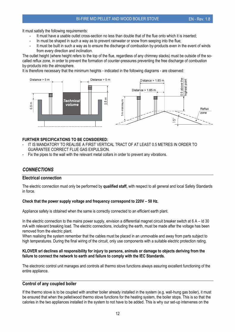
Extraordinary cleaning (WOOD SIDE)
To be performed at least twice a season.
Carry out routine cleaning;
With the supplied brush clean the elements on the combustion chamber. These can be accessed through the combustion chamber.
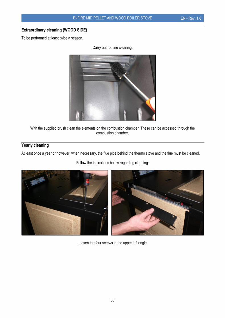
Yearly cleaning
At least once a year or however, when necessary, the flue pipe behind the thermo stove and the flue must be cleaned.
Follow the indications below regarding cleaning:
Loosen the four screws in the upper left angle.

31
BI-FIRE MID PELLET AND WOOD BOILER STOVE EN - Rev. 1.8
After having removed the upper left angle, slide the three lateral majolicas upwards (or the painted steel side).
Unscrews the stainless steel TEE inspection cap. Thoroughly clean the entire stainless steel pipe behind the thermo stove using the brush and re-mount the stainless
steel TEE inspection cap.

32
BI-FIRE MID PELLET AND WOOD BOILER STOVE EN - Rev. 1.8
After having loosened the two bolts, remove the lateral flue gas pass inspection outlet (pellet side).
Clean any obstructions in the lateral fumes passage and re-mount the inspection outlet.
Cleaning the ceramic glass
Always clean the glass when the stove is off and completely cold. Use a damp cloth and specific detergent for ceramic glasses. Do not use abrasive sponges.
Cleaning the flue
This operation must be performed at least once a year, at the start and half way through the winter season, and however when necessary. It is necessary to check the presence of any blockages in the flue before switching the thermo stove on, following a long period of inactivity. If cleaning is not performed, the functioning of the thermo stove and its components may be jeopardised. The frequency of cleaning of the thermo stove and the flue depend on the quality of the pellets and wood used. USE TOP QUALITY PELLETS AND WOOD TO OBTAIN THE BEST RESULTS.

33
BI-FIRE MID PELLET AND WOOD BOILER STOVE EN - Rev. 1.8
Maintenance of the boiler unit
The appliance is supplied with a special additive call LONG LIFE, designed to protect the boiler unit and heat exchangers from rust and to keep the water inside the boiler unit clean. LONG LIFE should be diluted to 2% with water inside the boiler unit. It can be poured directly into the boiler unit before or after filling it with water. For ease of use, a table is provided of the annual dilution dosages of LONG LIFE:
It is recommended to empty the boiler unit water every 2 years and remove any solid residues caked on the bottom. These residues reduce the effectiveness of LONG LIFE. The boiler unit should then be refilled and the optimum dosage of LONG LIFE should be added. If too much LONG LIFE is added by accident, empty and refill the boiler unit. Observance of the proper frequency for cleaning the boiler unit will prolong its life and is essential for the validity of the warranty. ATTENTION!!! NON-USE AND OR AN INCORRECT DOSAGE OF LONG LIFE WILL INVALIDATE THE WARRANTY ON THE BOILER UNIT. LONG LIFE gas been designed and tested on SICURO TOP products; KLOVER declines all liability arising from the use of LONG LIFE in products or applications other than those indicated. Contact your agent/retailer to purchase LONG LIFE.
C.A.T Maintenance
Timely and systematic maintenance is essential for guaranteeing correct operation, optimal heat performance and durability of the device. Therefore, qualified staff should check the appliance at least once a year at the beginning of the season. You must periodically check the seals because the latter guarantee the air- and water-tightness of the appliance and its good functioning; if they are worn or damaged you need to be replace them immediately by contacting a Klover Authorised technical assistance centre. For proper operation, the appliance must undergo routine maintenance performed by a Klover Authorised technical assistance centre at least once a year.
Boiler unit water
capacity
Recommended dose of LONG LIFE (2%) before filling
Recommended dose of LONG
LIFE (1%) after the first year
Recommended dose of LONG LIFE (2%)
after the second year
50 l 1000 ml 500 ml
Empty and clean out the boiler unit entirely Restore the water
level, adding 600 ml of LONG LIFE

34
BI-FIRE MID PELLET AND WOOD BOILER STOVE EN - Rev. 1.8
PCB PARAMETERS
The parameters stored on the PCB are essential for the correct operation. The following parameters are already stored during the testing of the appliance directly in the factory; these parameters are the result of special tests using several types of pellets and must not be changed without the authorisation of Klover srl so as not to impair the operation of the appliance. The company shall not be held liable for any damage caused by the incorrect entry of parameters.
Pre-load and additional parameters
PARAMETER DESCRIPTION VALUE
Pr45 ON time of the screw feed motor reducer in the pre-load phase 02”
Pr46 Stand-by time for passage to the “LOAD PELL” phase 02”
Pr47 Flue intake device speed in pre-load phase 35
Pr48 Wood fumes temperature in order to consider the wood side on 150 °C
Pr49 Minimum temperature for circulation pump start-up 50 °C
Additional parameters
PARAMETER DESCRIPTION VALUE
Pr55 Time for pellet side switch-on if the conditions exist after wood side switch-off 01’
General parameters
PARAMETER DESCRIPTION VALUE
Pr01 Ignition cycle maximum time 18’
Pr02 Flame stabilisation time during the “FIRE ON” phase 5’
Pr03 Time interval between two brazier cleaning operations 90’
Pr04 ON time of the screw feed motor reducer in the “LOAD PELL” phase 2,8”
Pr05 ON time of the screw feed motor reducer in the “FIRE ON” phase 2,2”
Pr06 ON time of the screw feed motor reducer in the “Po1” work phase 2,2”
Pr07 ON time of the screw feed motor reducer in the “Po2” work phase 3,3”
Pr08 ON time of the screw feed motor reducer in the “Po3” work phase 4,5”
Pr09 ON time of the screw feed motor reducer in the “Po4” work phase 5,8”
Pr10 ON time of the screw feed motor reducer in the “Po5” work phase 6,8”
Pr11 Temperature below which the pellet side switches on (on Pell On) 60 °C
Pr12 Temperature differential for switch-off 10 °C
Pr13 Flue gas minimum temperature in order to consider the thermo stove on 56 °C
Pr14 Flue gas maximum temperature accepted; if this occurs, the power is reduced to minimum and
the flue gas intake device speed is taken to the maximum value 260 °C
Pr15 Minimum temperature to be reached for pump switch-on 55 °C
Pr16 Flue gas intake speed in the “LOAD PELL” phase 30
Pr17 Flue gas intake speed in the “FIRE ON” phase 26
Pr18 Flue gas intake speed in the “Po1” work phase 8
Pr19 Flue gas intake speed in the “Po2” work phase 12
Pr20 Flue gas intake speed in the “Po3” work phase 18
Pr21 Flue gas intake speed in the “Po4” work phase 23
Pr22 Flue gas intake speed in the “Po5” work phase 27
Pr23 Time after which the thermo stove switches off if the boiler temperature is greater than that set in
the “Set H2O” 120’
Pr24 Brazier cleaning duration 50”
Pr25 Differential on the H20 Set (boiler thermostat) for 3-way valve switch-over 10 °C
Pr26 Differential on the Set Sani to switch-over the 3-way valve 5 °C
Pr27 Switch-over delay 60”
Pr28 Flue gas temperature threshold for thermo stove switch-off 80 °C

35
BI-FIRE MID PELLET AND WOOD BOILER STOVE EN - Rev. 1.8
MAIN WORDING ON THE DISPLAY
Read the instruction manual for all of the other wording shown on the display.
DISPLAY DESCRIPTION
Eco toFF
ROOM THERMOSTAT CONTACT OPEN
Eco Fumi
FLUE GAS TEMPERATURE TOO HIGH The thermo stove automatically slows the power until the flue gas temperature is lowered. Clean the internal “flue gas pass” as soon as possible.
OFF At te
STAND-BY This occurs when attempts are made to re-ignite the thermo stove before the flue gas intake device has finished the switch-off cycle.
NO FirE
NO FIRE This occurs when for some anomaly the thermo stove switches off without displaying alarms. It can also occur in the switch-on phase if the pellet side does not ignite.
no H2o
NO WATER It occurs when the water inside the thermo stove is not at correct level Remove the upper majolica and the lid in order to verify that the water inside the boiler body is at a level that it covers the exchangers completely.
Fun ASP
IGNITION PHASE OF THE FLUE GAS INTAKE DEVICE (duration about 10 seconds)
LoAd PELL
PELLET LOADING AND FLAME IGNITION PHASE (duration about 8-10 min)
FirE ON
FLAME STABILISATION PHASE (duration about 8-10 minutes)
Po1 , Po2 , 61 °C
Po 1…Po 5= work power from 1 to 5. Boiler water temperature in degrees centigrade
CooL FirE
BRAZIER CLEANING CYCLE
Eco H2o
ECONOMY FUNCTIONING Temperature in boiler the same or greater than that set via “SeT H2o”
StoP FirE
FIRE OFF This occurs with boiler temperature 10 °C over the temperature set with SeT H2O or after 2 hours functioning in economy. When the temperature in the boiler lowers by at least 10 °C the thermo stove starts automatically. It is also displayed when, the wood side switches off with the “Pell on” function active.
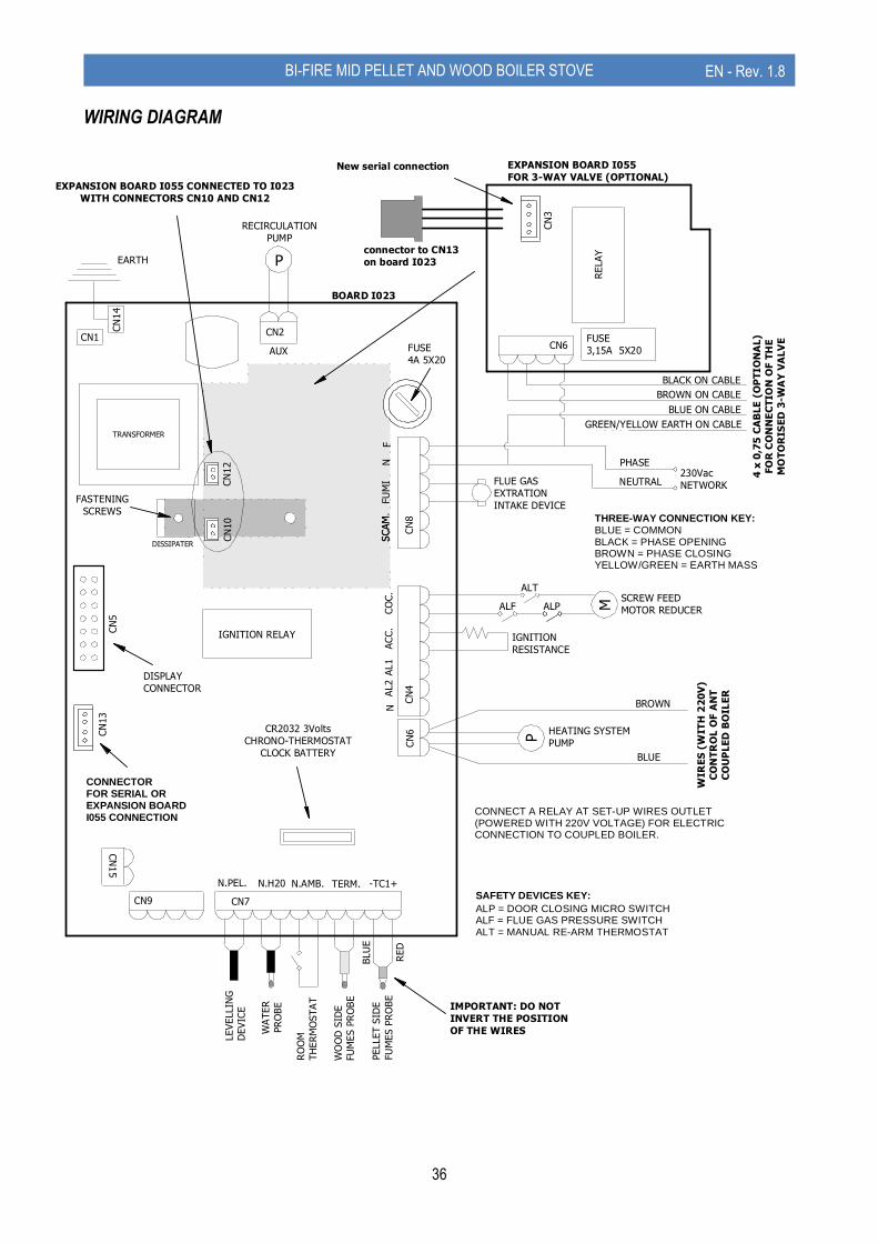
36
BI-FIRE MID PELLET AND WOOD BOILER STOVE EN - Rev. 1.8
WIRING DIAGRAM
TRANSFORMER
IGNITION RELAY
EARTH
FLUE GAS
EXTRATION
INTAKE DEVICE
PHASE
NEUTRAL230Vac
NETWORK
BROWN
BLUE
RECIRCULATION
PUMP
MSCREW FEED
MOTOR REDUCERALF ALP
IGNITION
RESISTANCE
RO
OM
TH
ER
MO
STA
T
CN
4CN
8
CN9
CN
13
CN
5
CN1CN2
CN
3
CN7
PELLET S
IDE
FU
MES P
RO
BE
FUSE
3,15A 5X20
N.PEL. N.H20 N.AMB. TERM.
BLU
E
RED
WA
TER
PR
OBE
-TC1+
ACC.
CO
C.
NF
SCAM
.FU
MI
NAL1
AL2
IMPORTANT: DO NOT
INVERT THE POSITION
OF THE WIRES
CN
6
CN6
RELAY
EXPANSION BOARD I055
FOR 3-WAY VALVE (OPTIONAL)
DISSIPATER
NF
SCAM
FU
MI
CN
15
FUSE
4A 5X20
connector to CN13
on board I023
New serial connection
EXPANSION BOARD I055 CONNECTED TO I023
WITH CONNECTORS CN10 AND CN12
CN
12
CN
10
FASTENING
SCREWS
BROWN ON CABLE
BLACK ON CABLE
BLUE ON CABLE
GREEN/YELLOW EARTH ON CABLE
BOARD I023
CN
14
DISPLAY
CONNECTORW
IRE
S (
WIT
H 2
20
V)
CO
NT
RO
L O
F A
NT
CO
UP
LE
D B
OIL
ER
4 x
0,7
5 C
AB
LE
(O
PT
IO
NA
L)
FO
R C
ON
NE
CT
ION
OF
TH
E
MO
TO
RIS
ED
3-W
AY
VA
LV
E
SCAM
.
AUX
ALT
WO
OD
SID
E
FU
MES P
RO
BE
P
HEATING SYSTEM
PUMP
P
LEVELLIN
G
DEVIC
E
SAFETY DEVICES KEY:
ALP = DOOR CLOSING MICRO SWITCHALF = FLUE GAS PRESSURE SWITCHALT = MANUAL RE-ARM THERMOSTAT
CONNECTORFOR SERIAL OREXPANSION BOARDI055 CONNECTION
CONNECT A RELAY AT SET-UP WIRES OUTLET(POWERED WITH 220V VOLTAGE) FOR ELECTRICCONNECTION TO COUPLED BOILER.
CR2032 3Volts
CHRONO-THERMOSTAT
CLOCK BATTERY
THREE-WAY CONNECTION KEY:BLUE = COMMONBLACK = PHASE OPENINGBROWN = PHASE CLOSINGYELLOW/GREEN = EARTH MASS

37
BI-FIRE MID PELLET AND WOOD BOILER STOVE EN - Rev. 1.8
WHAT HAPPENS IF...
...the thermo stove does not switch on In case of no ignition, the “NO FIRE” alarm is displayed. Hold button 4 (switch on/off) for a few seconds to restore the thermo stove to standard conditions (remove the alarm). ...lack of power for a few seconds Once the power is restored, the thermo stove immediately restarts from the status it had before the power outage (recovering the set work power). ... lack of power As soon as the power is restored after a power outage, the thermo stove sets on “STOP FIRE” mode and carries out the entire switch off cycle until its cooling. Once this phase is completed, the thermo stove can be normally switched on to proceed working at the set power. …the fire-door is open or closed improperly In case the door is open or closed improperly, the motor reducer cannot be powered electrically, not allowing the thermo stove to switch on. If the thermo door is opened during the normal operation, the thermo stove burns all the pellet in the brazier, activating the “ALAR NO FIRE” alarm (sudden switch off). The flue is dirty, blocked or not manufactured correctly. In case the flue is dirty, blocked or not manufactured correctly, the motor reducer cannot be powered electrically not allowing the thermo stove to switch on. If the flue blocks during the normal operation, the thermo stove burns all the pellet in the brazier, activating the “ALAR NO FIRE” alarm (sudden switch off). ...the stove is overheated In case of water over-temperature in the boiler, the message “ALAR HOT H2O” is first displayed followed by an acoustic alarm. At this point the motor reducer is not electrically powered, because the rearm safety thermostat is activated. Therefore the thermostat must be rearmed before switching on the stove.

38
BI-FIRE MID PELLET AND WOOD BOILER STOVE EN - Rev. 1.8
WARRANTY CONDITIONS
The warranty starts from the date of purchase of the product, which must be demonstrated by a delivery document and by the initial start-up report issued by the Authorised Technical Service Centre. These documents must be shown to the Technical Assistance Centre, if required. - A copy of the initial start-up report issued by the Authorised Technical Assistance Centre must be preserved along
with the proof of purchase receipt. - KLOVER s.r.l. disclaims any liability for accidents resulting from failure to comply with the instructions contained the
user and maintenance manual attached to the appliance. - Furthermore, KLOVER s.r.l. declines any liability arising from misuse of the product by the user, unauthorized
modifications and/or repairs, as well as the use of non-original spare parts or parts not suitable for this type of product.
KLOVER s.r.l. guarantees the quality of materials, good construction and functionality of the product for a period of 2 years, under the following conditions:
1. On its own unquestionable judgement, the device evidencing material or construction faults will be repaired or replaced; with the exception of all costs relating to transport, restoration (hydraulic disassembly and assembly operations, any masonry works and any other necessary intervention) and accessory materials.
2. The warranty does not cover: - the ceramic glass and ceramic-majolica and/or varnished steel linings, as they are very fragile and can get
accidentally damaged; - any part made of ceramic-majolica evidencing altered colour shades, pitting, cracks, shading and slight
dimensional variations, as these cannot be regarded as product defects but features deriving from the handmade processing techniques used;
- the cast iron brazier, the cast iron grid and plate, smoke deflector or flame arresters, gaskets, fuses or batteries inside the device's electronic system and any other removable component, where it is not proved that their condition is due to a manufacturing defect rather than the effects of wear;
- electric and electronic parts, in which the malfunction can be traced to a non-compliant electrical connection, natural disaster (lightning, electrical discharges, etc.) and variation in voltage other than the nominal voltage;
- any parameter calibration intervention due to the type of fuel or installation of the device. 3. The replaced components are guaranteed for the remaining period of the warranty, starting from the date of
purchase and/or for a period not exceeding 6 months. 4. The use of poor-quality wood pellets or other fuel could damage the components of the device thereby voiding the
relevant warranty and the manufacturer's liability. Therefore, we recommend using the fuel type indicated in our specifications;
5. Incorrect installation carried out by unqualified personnel, tampering with, failure to comply with the instructions contained in this "use and maintenance manual" and those regarding “workmanlike installation” shall void any warranty rights; the same applies to damages deriving from external factors. At all events, any compensation for direct or indirect damages is excluded, regardless of the nature and cause of the damages.
6. Please bear in mind that the goods travel under the customer’s responsibility, even if delivered carriage free, therefore we shall not be held liable for any damages due to loading and unloading operations, accidental knocks, storage in unsuitable places, etc.
7. The boiler unit of water-based products only connected to a heating and/or sanitary water system is guaranteed for 5 years, at the above-mentioned conditions.
8. The warranty is to be considered valid only if the initial start-up report and warranty start is duly completed in all its parts by the Authorised Technical Assistance Centre at the first ignition. For the validity of the warranty, the first ignition must only be carried out by the Authorized Technical Assistance Centre within 3 months from the date of purchase and no later than 30 days from date of installation;
For any disputes the Courts in Verona have sole jurisdiction.

Cod. CS.IST.BFM-EN
KLOVER Srl
Via A. Volta, 8 37047 San Bonifacio (VR)
P.IVA 02324280235 www.klover.it