Embed Size (px)
Citation preview
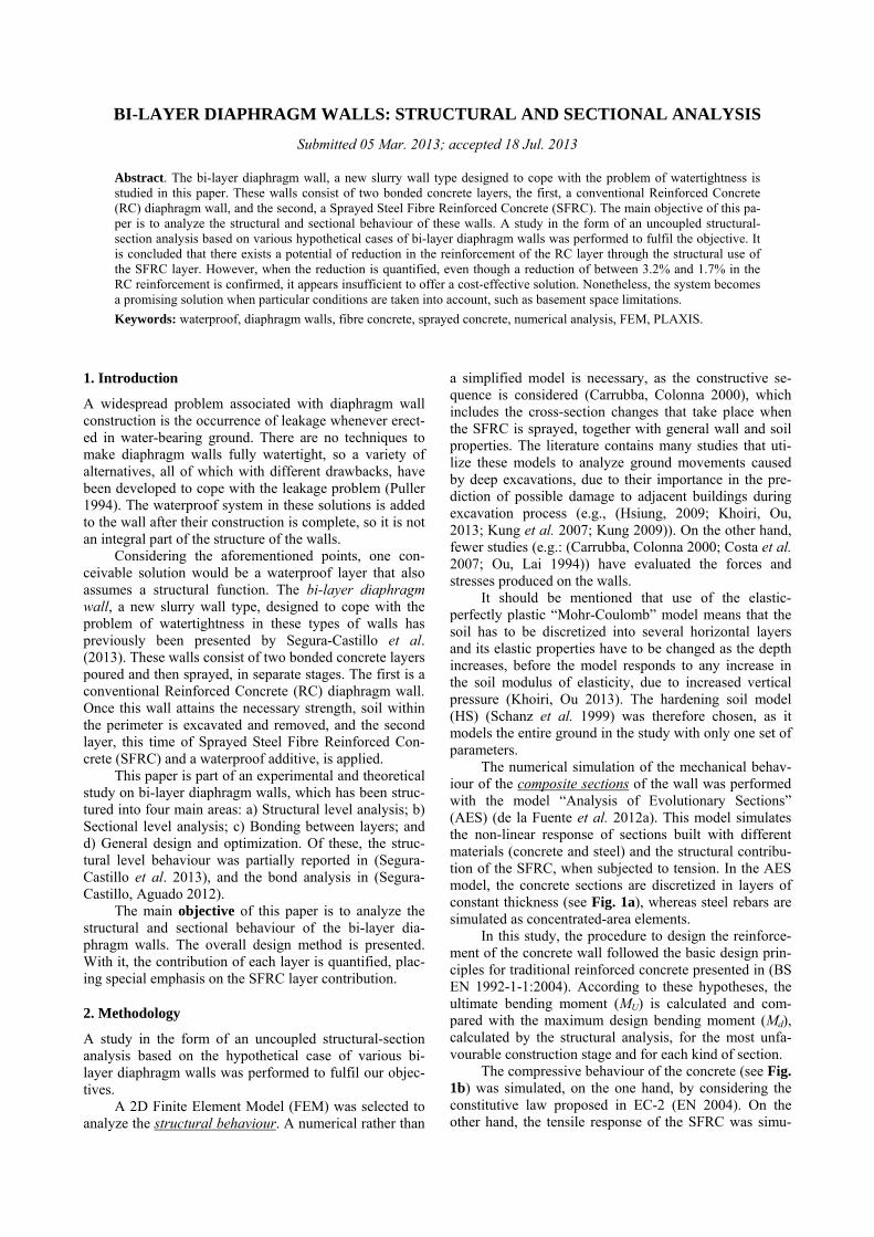
BI-LAYER DIAPHRAGM WALLS: STRUCTURAL AND SECTIONAL ANALYSIS
Submitted 05 Mar. 2013; accepted 18 Jul. 2013
Abstract. The bi-layer diaphragm wall, a new slurry wall type designed to cope with the problem of watertightness is studied in this paper. These walls consist of two bonded concrete layers, the first, a conventional Reinforced Concrete (RC) diaphragm wall, and the second, a Sprayed Steel Fibre Reinforced Concrete (SFRC). The main objective of this pa-per is to analyze the structural and sectional behaviour of these walls. A study in the form of an uncoupled structural-section analysis based on various hypothetical cases of bi-layer diaphragm walls was performed to fulfil the objective. It is concluded that there exists a potential of reduction in the reinforcement of the RC layer through the structural use of the SFRC layer. However, when the reduction is quantified, even though a reduction of between 3.2% and 1.7% in the RC reinforcement is confirmed, it appears insufficient to offer a cost-effective solution. Nonetheless, the system becomes a promising solution when particular conditions are taken into account, such as basement space limitations.
Keywords: waterproof, diaphragm walls, fibre concrete, sprayed concrete, numerical analysis, FEM, PLAXIS.
1. Introduction
A widespread problem associated with diaphragm wall construction is the occurrence of leakage whenever erect-ed in water-bearing ground. There are no techniques to make diaphragm walls fully watertight, so a variety of alternatives, all of which with different drawbacks, have been developed to cope with the leakage problem (Puller 1994). The waterproof system in these solutions is added to the wall after their construction is complete, so it is not an integral part of the structure of the walls.
Considering the aforementioned points, one con-ceivable solution would be a waterproof layer that also assumes a structural function. The bi-layer diaphragm wall, a new slurry wall type, designed to cope with the problem of watertightness in these types of walls has previously been presented by Segura-Castillo et al. (2013). These walls consist of two bonded concrete layers poured and then sprayed, in separate stages. The first is a conventional Reinforced Concrete (RC) diaphragm wall. Once this wall attains the necessary strength, soil within the perimeter is excavated and removed, and the second layer, this time of Sprayed Steel Fibre Reinforced Con-crete (SFRC) and a waterproof additive, is applied.
This paper is part of an experimental and theoretical study on bi-layer diaphragm walls, which has been struc-tured into four main areas: a) Structural level analysis; b) Sectional level analysis; c) Bonding between layers; and d) General design and optimization. Of these, the struc-tural level behaviour was partially reported in (Segura-Castillo et al. 2013), and the bond analysis in (Segura-Castillo, Aguado 2012).
The main objective of this paper is to analyze the structural and sectional behaviour of the bi-layer dia-phragm walls. The overall design method is presented. With it, the contribution of each layer is quantified, plac-ing special emphasis on the SFRC layer contribution.
2. Methodology
A study in the form of an uncoupled structural-section analysis based on the hypothetical case of various bi-layer diaphragm walls was performed to fulfil our objec-tives.
A 2D Finite Element Model (FEM) was selected to analyze the structural behaviour. A numerical rather than
a simplified model is necessary, as the constructive se-quence is considered (Carrubba, Colonna 2000), which includes the cross-section changes that take place when the SFRC is sprayed, together with general wall and soil properties. The literature contains many studies that uti-lize these models to analyze ground movements caused by deep excavations, due to their importance in the pre-diction of possible damage to adjacent buildings during excavation process (e.g., (Hsiung, 2009; Khoiri, Ou, 2013; Kung et al. 2007; Kung 2009)). On the other hand, fewer studies (e.g.: (Carrubba, Colonna 2000; Costa et al. 2007; Ou, Lai 1994)) have evaluated the forces and stresses produced on the walls.
It should be mentioned that use of the elastic-perfectly plastic “Mohr-Coulomb” model means that the soil has to be discretized into several horizontal layers and its elastic properties have to be changed as the depth increases, before the model responds to any increase in the soil modulus of elasticity, due to increased vertical pressure (Khoiri, Ou 2013). The hardening soil model (HS) (Schanz et al. 1999) was therefore chosen, as it models the entire ground in the study with only one set of parameters.
The numerical simulation of the mechanical behav-iour of the composite sections of the wall was performed with the model “Analysis of Evolutionary Sections” (AES) (de la Fuente et al. 2012a). This model simulates the non-linear response of sections built with different materials (concrete and steel) and the structural contribu-tion of the SFRC, when subjected to tension. In the AES model, the concrete sections are discretized in layers of constant thickness (see Fig. 1a), whereas steel rebars are simulated as concentrated-area elements.
In this study, the procedure to design the reinforce-ment of the concrete wall followed the basic design prin-ciples for traditional reinforced concrete presented in (BS EN 1992-1-1:2004). According to these hypotheses, the ultimate bending moment (MU) is calculated and com-pared with the maximum design bending moment (Md), calculated by the structural analysis, for the most unfa-vourable construction stage and for each kind of section.
The compressive behaviour of the concrete (see Fig. 1b) was simulated, on the one hand, by considering the constitutive law proposed in EC-2 (EN 2004). On the other hand, the tensile response of the SFRC was simu-
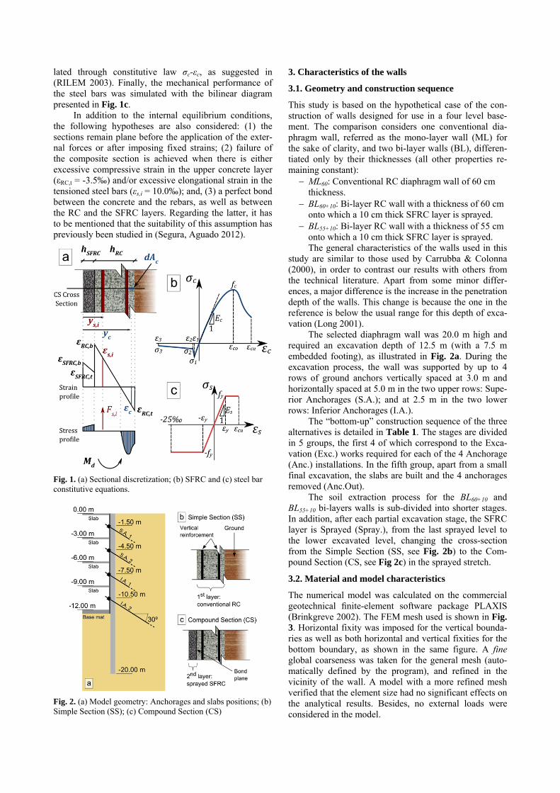
lated through constitutive law σc-εc, as suggested in (RILEM 2003). Finally, the mechanical performance of the steel bars was simulated with the bilinear diagram presented in Fig. 1c.
In addition to the internal equilibrium conditions, the following hypotheses are also considered: (1) the sections remain plane before the application of the exter-nal forces or after imposing fixed strains; (2) failure of the composite section is achieved when there is either excessive compressive strain in the upper concrete layer (εRC,t = -3.5‰) and/or excessive elongational strain in the tensioned steel bars (εs,i = 10.0‰); and, (3) a perfect bond between the concrete and the rebars, as well as between the RC and the SFRC layers. Regarding the latter, it has to be mentioned that the suitability of this assumption has previously been studied in (Segura, Aguado 2012).
Fig. 1. (a) Sectional discretization; (b) SFRC and (c) steel bar constitutive equations.
Fig. 2. (a) Model geometry: Anchorages and slabs positions; (b) Simple Section (SS); (c) Compound Section (CS)
3. Characteristics of the walls
3.1. Geometry and construction sequence
This study is based on the hypothetical case of the con-struction of walls designed for use in a four level base-ment. The comparison considers one conventional dia-phragm wall, referred as the mono-layer wall (ML) for the sake of clarity, and two bi-layer walls (BL), differen-tiated only by their thicknesses (all other properties re-maining constant):
ML60: Conventional RC diaphragm wall of 60 cm thickness.
BL60+10: Bi-layer RC wall with a thickness of 60 cm onto which a 10 cm thick SFRC layer is sprayed.
BL55+10: Bi-layer RC wall with a thickness of 55 cm onto which a 10 cm thick SFRC layer is sprayed. The general characteristics of the walls used in this
study are similar to those used by Carrubba & Colonna (2000), in order to contrast our results with others from the technical literature. Apart from some minor differ-ences, a major difference is the increase in the penetration depth of the walls. This change is because the one in the reference is below the usual range for this depth of exca-vation (Long 2001).
The selected diaphragm wall was 20.0 m high and required an excavation depth of 12.5 m (with a 7.5 m embedded footing), as illustrated in Fig. 2a. During the excavation process, the wall was supported by up to 4 rows of ground anchors vertically spaced at 3.0 m and horizontally spaced at 5.0 m in the two upper rows: Supe-rior Anchorages (S.A.); and at 2.5 m in the two lower rows: Inferior Anchorages (I.A.).
The “bottom-up” construction sequence of the three alternatives is detailed in Table 1. The stages are divided in 5 groups, the first 4 of which correspond to the Exca-vation (Exc.) works required for each of the 4 Anchorage (Anc.) installations. In the fifth group, apart from a small final excavation, the slabs are built and the 4 anchorages removed (Anc.Out).
The soil extraction process for the BL60+10 and BL55+10 bi-layers walls is sub-divided into shorter stages. In addition, after each partial excavation stage, the SFRC layer is Sprayed (Spray.), from the last sprayed level to the lower excavated level, changing the cross-section from the Simple Section (SS, see Fig. 2b) to the Com-pound Section (CS, see Fig 2c) in the sprayed stretch.
3.2. Material and model characteristics
The numerical model was calculated on the commercial geotechnical finite-element software package PLAXIS (Brinkgreve 2002). The FEM mesh used is shown in Fig. 3. Horizontal fixity was imposed for the vertical bounda-ries as well as both horizontal and vertical fixities for the bottom boundary, as shown in the same figure. A fine global coarseness was taken for the general mesh (auto-matically defined by the program), and refined in the vicinity of the wall. A model with a more refined mesh verified that the element size had no significant effects on the analytical results. Besides, no external loads were considered in the model.
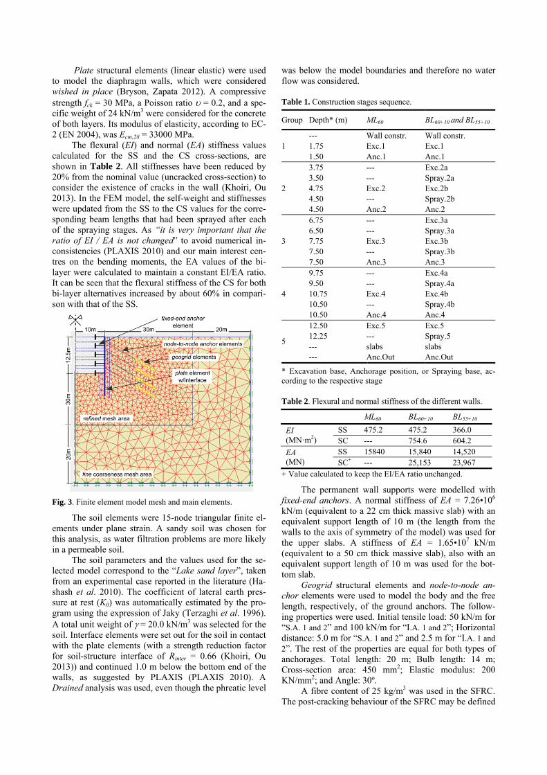
Plate structural elements (linear elastic) were used to model the diaphragm walls, which were considered wished in place (Bryson, Zapata 2012). A compressive strength fck = 30 MPa, a Poisson ratio = 0.2, and a spe-cific weight of 24 kN/m3 were considered for the concrete of both layers. Its modulus of elasticity, according to EC-2 (EN 2004), was Ecm,28 = 33000 MPa.
The flexural (EI) and normal (EA) stiffness values calculated for the SS and the CS cross-sections, are shown in Table 2. All stiffnesses have been reduced by 20% from the nominal value (uncracked cross-section) to consider the existence of cracks in the wall (Khoiri, Ou 2013). In the FEM model, the self-weight and stiffnesses were updated from the SS to the CS values for the corre-sponding beam lengths that had been sprayed after each of the spraying stages. As “it is very important that the ratio of EI / EA is not changed” to avoid numerical in-consistencies (PLAXIS 2010) and our main interest cen-tres on the bending moments, the EA values of the bi-layer were calculated to maintain a constant EI/EA ratio. It can be seen that the flexural stiffness of the CS for both bi-layer alternatives increased by about 60% in compari-son with that of the SS.
Fig. 3. Finite element model mesh and main elements.
The soil elements were 15-node triangular finite el-ements under plane strain. A sandy soil was chosen for this analysis, as water filtration problems are more likely in a permeable soil.
The soil parameters and the values used for the se-lected model correspond to the “Lake sand layer”, taken from an experimental case reported in the literature (Ha-shash et al. 2010). The coefficient of lateral earth pres-sure at rest (K0) was automatically estimated by the pro-gram using the expression of Jaky (Terzaghi et al. 1996). A total unit weight of = 20.0 kN/m3 was selected for the soil. Interface elements were set out for the soil in contact with the plate elements (with a strength reduction factor for soil-structure interface of Rinter = 0.66 (Khoiri, Ou 2013)) and continued 1.0 m below the bottom end of the walls, as suggested by PLAXIS (PLAXIS 2010). A Drained analysis was used, even though the phreatic level
was below the model boundaries and therefore no water flow was considered.
Table 1. Construction stages sequence.
Group Depth* (m) ML60 BL60+10 and BL55+10
1 --- Wall constr. Wall constr. 1.75 Exc.1 Exc.1 1.50 Anc.1 Anc.1
2
3.75 --- Exc.2a 3.50 --- Spray.2a 4.75 Exc.2 Exc.2b 4.50 --- Spray.2b 4.50 Anc.2 Anc.2
3
6.75 --- Exc.3a 6.50 --- Spray.3a 7.75 Exc.3 Exc.3b 7.50 --- Spray.3b 7.50 Anc.3 Anc.3
4
9.75 --- Exc.4a 9.50 --- Spray.4a 10.75 Exc.4 Exc.4b 10.50 --- Spray.4b 10.50 Anc.4 Anc.4
5
12.50 Exc.5 Exc.5 12.25 --- Spray.5 --- slabs slabs --- Anc.Out Anc.Out
* Excavation base, Anchorage position, or Spraying base, ac-cording to the respective stage
Table 2. Flexural and normal stiffness of the different walls.
ML60 BL60+10 BL55+10
EI (MN·m2)
SS 475.2 475.2 366.0 SC --- 754.6 604.2
EA (MN)
SS 15840 15,840 14,520 SC+ --- 25,153 23,967
+ Value calculated to keep the EI/EA ratio unchanged.
The permanent wall supports were modelled with fixed-end anchors. A normal stiffness of EA = 7.26•106 kN/m (equivalent to a 22 cm thick massive slab) with an equivalent support length of 10 m (the length from the walls to the axis of symmetry of the model) was used for the upper slabs. A stiffness of EA = 1.65•107 kN/m (equivalent to a 50 cm thick massive slab), also with an equivalent support length of 10 m was used for the bot-tom slab.
Geogrid structural elements and node-to-node an-chor elements were used to model the body and the free length, respectively, of the ground anchors. The follow-ing properties were used. Initial tensile load: 50 kN/m for “S.A. 1 and 2” and 100 kN/m for “I.A. 1 and 2”; Horizontal distance: 5.0 m for “S.A. 1 and 2” and 2.5 m for “I.A. 1 and 2”. The rest of the properties are equal for both types of anchorages. Total length: 20 m; Bulb length: 14 m; Cross-section area: 450 mm2; Elastic modulus: 200 KN/mm2; and Angle: 30º.
A fibre content of 25 kg/m3 was used in the SFRC. The post-cracking behaviour of the SFRC may be defined
by the expressions given in (de la Fuente et al. 2012b). The nominal cover used for the RC bars was 70 mm.
4. Structural results
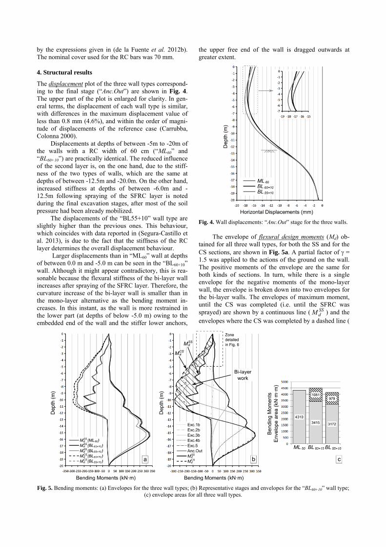
The displacement plot of the three wall types correspond-ing to the final stage (“Anc.Out”) are shown in Fig. 4. The upper part of the plot is enlarged for clarity. In gen-eral terms, the displacement of each wall type is similar, with differences in the maximum displacement value of less than 0.8 mm (4.6%), and within the order of magni-tude of displacements of the reference case (Carrubba, Colonna 2000).
Displacements at depths of between -5m to -20m of the walls with a RC width of 60 cm (“ML60” and “BL60+10”) are practically identical. The reduced influence of the second layer is, on the one hand, due to the stiff-ness of the two types of walls, which are the same at depths of between -12.5m and -20.0m. On the other hand, increased stiffness at depths of between -6.0m and -12.5m following spraying of the SFRC layer is noted during the final excavation stages, after most of the soil pressure had been already mobilized.
The displacements of the “BL55+10” wall type are slightly higher than the previous ones. This behaviour, which coincides with data reported in (Segura-Castillo et al. 2013), is due to the fact that the stiffness of the RC layer determines the overall displacement behaviour.
Larger displacements than in “ML60” wall at depths of between 0.0 m and -5.0 m can be seen in the “BL60+10” wall. Although it might appear contradictory, this is rea-sonable because the flexural stiffness of the bi-layer wall increases after spraying of the SFRC layer. Therefore, the curvature increase of the bi-layer wall is smaller than in the mono-layer alternative as the bending moment in-creases. In this instant, as the wall is more restrained in the lower part (at depths of below -5.0 m) owing to the embedded end of the wall and the stiffer lower anchors,
the upper free end of the wall is dragged outwards at greater extent.
Fig. 4. Wall displacements: “Anc.Out” stage for the three walls. The envelope of flexural design moments (Md) ob-
tained for all three wall types, for both the SS and for the CS sections, are shown in Fig. 5a. A partial factor of = 1.5 was applied to the actions of the ground on the wall. The positive moments of the envelope are the same for both kinds of sections. In turn, while there is a single envelope for the negative moments of the mono-layer wall, the envelope is broken down into two envelopes for the bi-layer walls. The envelopes of maximum moment, until the CS was completed (i.e. until the SFRC was sprayed) are shown by a continuous line ( ) and the envelopes where the CS was completed by a dashed line (
SSdM
Fig. 5. Bending moments: (a) Envelopes for the three wall types; (b) Representative stages and envelopes for the “BL60+10” wall type; (c) envelope areas for all three wall types.
). The way these envelopes were generated is ex-plained below in greater detail. In general terms, the en-velopes are qualitatively similar and within the order of magnitude of the reference case (Carrubba, Colonna 2000).
Comparing the bi-layer walls, it can be seen that the “BL60+10” shows larger moments than the “BL55+10” along the whole length of the wall. This is a consequence of the greater stiffness of the RC layer and, therefore, greater stiffness both in the SS and in the CS cross-section.
The “ML60” and “BL60+10” wall types show practi-cally identical envelopes in the embedded section of the wall (between depths -12.5m and -20.0m). In this section, both walls have the same cross-section (i.e., the RC layer) for all the stages. The biggest differences between these wall types was registered in the centre of the walls, be-tween depths -5.0m and -12.0m, in which the “BL60+10” envelope was larger. As the SFRC layer is sprayed, the upper stretches become stiffer, diminishing any relative collaboration of the embedded part of the wall.
The bending moments of the “BL60+10” wall type are detailed in Fig. 5b, in which light-grey lines indicate the moment of the representative stages of each excavation stage. The interval between the envelopes previously introduced in Fig. 5a ( and ) is highlighted with slanting lines. This area represents the increase in the moments after spraying the SFRC layer (i.e., where the CS cross-section is working).
As stated in Segura et al. (2013), the highlighted ar-ea represents the potential use of the bi-layer wall, since it is possible to cover these moments with the resistance of the CS section. It can be seen that for the depths where the CS section is present, a significant portion of the bending moments are developed after the SFRC layer has been sprayed. These increases range from 30% to 269% at depths of between -2.5m and -11.0m, with an average increase of 123% in the design moment of those depths after the SFRC layer is sprayed.
The value of the area within the SS cross section envelope is represented with a solid bar graph to compare the three wall types, in Fig. 5c. The value of the area of the CS cross section (as shown in Fig. 5b) is also plotted (slanting lines). It may be noted that the potential of use of the SFRC layer covers approximately 25% of the area of moments.
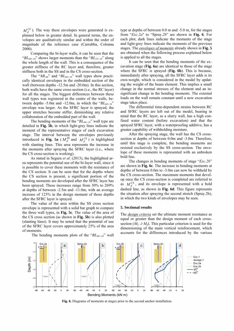
The bending moments plots of the “BL60+10” wall
type at depths of between 0.0 m and -5.0 m, for the stages from “Exc.2a" to “Spray.2b” are shown in Fig. 6. For each plot, dark lines indicate the moments of the stage and light-grey lines indicate the moments of the previous stages. The envelopes of moments already shown in Fig. 5 are obtained when the following process explained below is applied to all the stages.
It can be seen that the bending moments of the ex-cavation stage (Fig. 6a) are identical to those of the stage where the SFRC is sprayed (Fig. 6b). This is because, immediately after spraying, all the SFRC layer adds is its own-weight, which is considered in the model by updat-ing the weight of the beam element. This implies a small change in the normal stresses of the element and an in-significant change in the bending moments. The external loads on the wall remain constant until a new excavation stage takes place.
The differential time-dependent strains between RC and SFRC layers are left out of the model, bearing in mind that the RC layer, as a slurry wall, has a high con-fined water content (before excavation) and that the sprayed SFRC layer, with a waterproofing additive, has a greater capability of withholding moisture.
After the spraying stage, the wall has the CS cross-section at depths of between 0.0m and -3.0m. Therefore, until this stage is complete, the bending moments are resisted exclusively by the SS cross-section. The enve-lope of these moments is represented with an unbroken bold line.
The changes in bending moments of stage “Exc.2b” are shown in Fig. 6c. The increase in bending moments at depths of between 0.0m to -3.0m can now be withheld by the CS cross-section. The maximum moments that devel-op once the CS cross-section is completed are referred to as , and its envelope is represented with a bold dashed line, as shown in Fig. 6d. This figure represents the situation after spraying the second stretch (Spray.2b), in which the two kinds of envelopes may be seen.
5. Sectional results
The design criteria set the ultimate moment resistance as equal or greater than the design moment of each cross-section (MU Md). This particular criterion is used for the dimensioning of the main vertical reinforcement, which accounts for the differences introduced by the various
CSdM
SSdM CS
dM
CSdM
Fig. 6. Diagrams of moments at stages prior to the second anchor installation.
wall types analysed in this study. Therefore, secondary reinforcements (e.g., for transversal stresses or time-dependant effects) are neglected in this study as they are considered the same for all three wall types. The shear force, and its reinforcement, is also neglected as it is not usually a determinant in the design of the walls.
Reinforcement of the RC layer involves: a) a sym-metric reinforcement on both sides of the wall with the minimum mechanical reinforcement “AS,min” (according to the EHE-08 code (CPH 2008)); and b) one extra rein-forcement per side of the Wall, one for the positive mo-ments “As,+”, and another one for the negative ones “As,-”, to cover the extra moment that the minimum reinforce-ment does not cover. The addition of both areas “AT” was used in the calculations for cross-sections in which both reinforcements were present. Only tensioned bars were used in the calculation.
Two ultimate moment resistances, whether or not we consider the SFRC layer, were obtained for the bi-layer wall types, one for the SS (“ ”) and another for the CS cross-section (“ ”). In this way, the design condition for the bi-layer walls can be differentiated ac-cording to the type of section that is active at each instant, establishing that every cross-section must at every instant simultaneously satisfy both relationships given by the following inequalities:
SSd
SSU MM (1)
CSd
CSU MM (2)
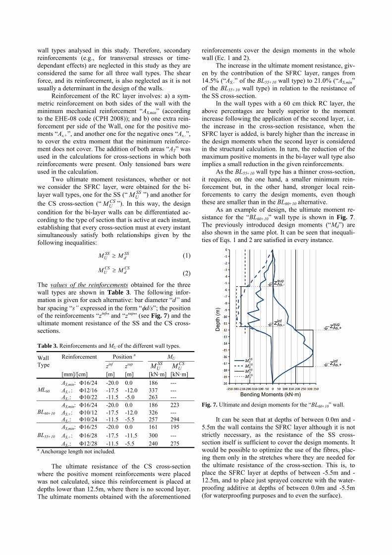
The values of the reinforcements obtained for the three wall types are shown in Table 3. The following infor-mation is given for each alternative: bar diameter “d” and bar spacing “s” expressed in the form “d/s”; the position of the reinforcements “zinf” and “zsup” (see Fig. 7) and the ultimate moment resistance of the SS and the CS cross-sections.
Table 3. Reinforcements and MU of the different wall types.
Wall Type
Reinforcement Position a MU
zinf zsup [mm]/[cm] [m] [m] [kN·m] [kN·m]
ML60 AS,min: Φ16/24 -20.0 0.0 186 --- AS,+: Φ12/16 -17.5 -12.0 337 --- AS,-: Φ10/22 -11.5 -5.0 263 ---
BL60+10 AS,min: Φ16/24 -20.0 0.0 186 223 AS,+: Φ10/12 -17.5 -12.0 326 --- AS,-: Φ10/24 -11.5 -5.5 257 294
BL55+10 AS,min: Φ16/25 -20.0 0.0 161 195
AS,+: Φ16/28 -17.5 -11.5 300 --- AS,-: Φ12/28 -11.5 -5.5 240 275
a Anchorage length not included. The ultimate resistance of the CS cross-section
where the positive moment reinforcements were placed was not calculated, since this reinforcement is placed at depths lower than 12.5m, where there is no second layer. The ultimate moments obtained with the aforementioned
reinforcements cover the design moments in the whole wall (Ec. 1 and 2).
The increase in the ultimate moment resistance, giv-en by the contribution of the SFRC layer, ranges from 14.5% (“AS,-” of the BL55+10 wall type) to 21.0% (“AS,min” of the BL55+10 wall type) in relation to the resistance of the SS cross-section.
In the wall types with a 60 cm thick RC layer, the above percentages are barely superior to the moment increase following the application of the second layer, i.e. the increase in the cross-section resistance, when the SFRC layer is added, is barely higher than the increase in the design moments when the second layer is considered in the structural calculation. In turn, the reduction of the maximum positive moments in the bi-layer wall type also implies a small reduction in the given reinforcements.
As the BL55+10 wall type has a thinner cross-section, it requires, on the one hand, a smaller minimum rein-forcement but, in the other hand, stronger local rein-forcements to carry the design moments, even though these are smaller than in the BL60+10 alternative.
As an example of design, the ultimate moment re-sistance for the “BL60+10” wall type is shown in Fig. 7. The previously introduced design moments (“Md”) are also shown in the same plot. It can be seen that inequali-ties of Eqs. 1 and 2 are satisfied in every instance.
Fig. 7. Ultimate and design moments for the “BL60+10” wall. It can be seen that at depths of between 0.0m and -
5.5m the wall contains the SFRC layer although it is not strictly necessary, as the resistance of the SS cross-section itself is sufficient to cover the design moments. It would be possible to optimize the use of the fibres, plac-ing them only in the stretches where they are needed for the ultimate resistance of the cross-section. This is, to place the SFRC layer at depths of between -5.5m and -12.5m, and to place just sprayed concrete with the water-proofing additive at depths of between 0.0m and -5.5m (for waterproofing purposes and to even the surface).
SSUM
CSUM
SSUM CS
UM
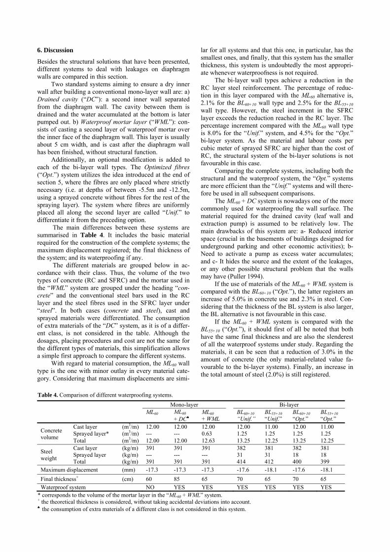
6. Discussion
Besides the structural solutions that have been presented, different systems to deal with leakages on diaphragm walls are compared in this section.
Two standard systems aiming to ensure a dry inner wall after building a conventional mono-layer wall are: a) Drained cavity (“DC”): a second inner wall separated from the diaphragm wall. The cavity between them is drained and the water accumulated at the bottom is later pumped out. b) Waterproof mortar layer (“WML”): con-sists of casting a second layer of waterproof mortar over the inner face of the diaphragm wall. This layer is usually about 5 cm width, and is cast after the diaphragm wall has been finished, without structural function.
Additionally, an optional modification is added to each of the bi-layer wall types. The Optimized fibres (“Opt.”) system utilizes the idea introduced at the end of section 5, where the fibres are only placed where strictly necessary (i.e. at depths of between -5.5m and -12.5m, using a sprayed concrete without fibres for the rest of the spraying layer). The system where fibres are uniformly placed all along the second layer are called “Unif.” to differentiate it from the preceding option.
The main differences between these systems are summarised in Table 4. It includes the basic material required for the construction of the complete systems; the maximum displacement registered; the final thickness of the system; and its waterproofing if any.
The different materials are grouped below in ac-cordance with their class. Thus, the volume of the two types of concrete (RC and SFRC) and the mortar used in the “WML” system are grouped under the heading “con-crete” and the conventional steel bars used in the RC layer and the steel fibres used in the SFRC layer under “steel”. In both cases (concrete and steel), cast and sprayed materials were differentiated. The consumption of extra materials of the “DC” system, as it is of a differ-ent class, is not considered in the table. Although the dosages, placing procedures and cost are not the same for the different types of materials, this simplification allows a simple first approach to compare the different systems.
With regard to material consumption, the ML60 wall type is the one with minor outlay in every material cate-gory. Considering that maximum displacements are simi-
lar for all systems and that this one, in particular, has the smallest ones, and finally, that this system has the smaller thickness, this system is undoubtedly the most appropri-ate whenever waterproofness is not required.
The bi-layer wall types achieve a reduction in the RC layer steel reinforcement. The percentage of reduc-tion in this layer compared with the ML60 alternative is, 2.1% for the BL60+10 wall type and 2.5% for the BL55+10 wall type. However, the steel increment in the SFRC layer exceeds the reduction reached in the RC layer. The percentage increment compared with the ML60 wall type is 8.0% for the “Unif.” system, and 4.5% for the “Opt.” bi-layer system. As the material and labour costs per cubic meter of sprayed SFRC are higher than the cost of RC, the structural system of the bi-layer solutions is not favourable in this case.
Comparing the complete systems, including both the structural and the waterproof system, the “Opt.” systems are more efficient than the “Unif.” systems and will there-fore be used in all subsequent comparisons.
The ML60 + DC system is nowadays one of the more commonly used for waterproofing the wall surface. The material required for the drained cavity (leaf wall and extraction pump) is assumed to be relatively low. The main drawbacks of this system are: a- Reduced interior space (crucial in the basements of buildings designed for underground parking and other economic activities); b-Need to activate a pump as excess water accumulates; and c- It hides the source and the extent of the leakages, or any other possible structural problem that the walls may have (Puller 1994).
If the use of materials of the ML60 + WML system is compared with the BL60+10 (“Opt.”), the latter registers an increase of 5.0% in concrete use and 2.3% in steel. Con-sidering that the thickness of the BL system is also larger, the BL alternative is not favourable in this case.
If the ML60 + WML system is compared with the BL55+10 (“Opt.”), it should first of all be noted that both have the same final thickness and are also the slenderest of all the waterproof systems under study. Regarding the materials, it can be seen that a reduction of 3.0% in the amount of concrete (the only material-related value fa-vourable to the bi-layer systems). Finally, an increase in the total amount of steel (2.0%) is still registered.
Table 4. Comparison of different waterproofing systems.
Mono-layer Bi-layer
ML60
ML60 + DC
ML60
+ WML
BL60+10
“Unif.” BL55+10 “Unif.”
BL60+10
“Opt.” BL55+10 “Opt.”
Concrete volume
Cast layer (m3/m) 12.00 12.00 12.00 12.00 11.00 12.00 11.00 Sprayed layer* (m3/m) --- --- 0.63 1.25 1.25 1.25 1.25 Total (m3/m) 12.00 12.00 12.63 13.25 12.25 13.25 12.25
Steel weight
Cast layer (kg/m) 391 391 391 382 381 382 381 Sprayed layer (kg/m) --- --- --- 31 31 18 18 Total (kg/m) 391 391 391 414 412 400 399
Maximum displacement (mm) -17.3 -17.3 -17.3 -17.6 -18.1 -17.6 -18.1
Final thickness+ (cm) 60 85 65 70 65 70 65
Waterproof system NO YES YES YES YES YES YES * corresponds to the volume of the mortar layer in the “ML60 + WML” system. + the theoretical thickness is considered, without taking accidental deviations into account. the consumption of extra materials of a different class is not considered in this system.
7. Conclusions
A design method for the bi-layer diaphragm walls, a new type of slurry wall, has been presented. It allows two levels of comparison, the first of which is based on the structural analysis and the second on the final design, where the comparison includes final material use. The structural behaviour of a conventional ML wall (60 cm width RC layer) has been compared with two BL alterna-tives (60 cm and 55 cm width RC layer plus 10 cm width SFRC layer). Furthermore, starting with these wall types, several systems to deal with leakages have been added to the comparison. The main conclusions are summarized in the following points.
There exists a potential of reduction in the rein-forcement of the RC layer of the diaphragm walls through the structural use of the SFRC layer. This potential is measured by the area of moments envelope covered by the simple section ( ). This area is reduced 21% and 26% in both BL alternatives, compared with the ML wall.
However, it is not possible to take advantage of all this potential in the design process for two reasons that are explained as follows. The increase from the to
the is, on average, 123% of the (at depths of between -2.5m and -11.0m). Besides, the increase from the to the are, in this case, between 15% and 20% of the CS
UM . This means that, if the SS section is designed to cover only the SS design moments, the sec-ond layer does not provide the additional bending strength to the CS cross-section to cover the moments developed after the second layer is sprayed. Therefore, the SS sections should be designed to cover the SS
dM and part of the CS
dM moments. The second reason, is that the minimum SS
UM , given by the minimum reinforcement,
already covers a part of the design moments.
Even though a reduction in the RC reinforcement is confirmed for both wall types (2.1% and 2.5%), it ap-pears insufficient to compensate for the extra technolo-gies and consumption of materials to build the bi-layer solutions. Nonetheless, the complete waterproof system becomes an interesting solution when particular condi-tions are taken into account, such as basement space limi-tations or if continuous maintenance wants to be avoided.
Future work should include a parametric study to evaluate, by means of the two level comparison presented in this study, the influence of the general condition and wall design on the profitability of the bi-layer wall type.
References Brinkgreve, R. (2002). PLAXIS 2D, Version 8. A.A. Balkema
Publishers, Lisse, The Netherlands. Bryson, L. S.; Zapata-Medina, D. G. (2012). Method for Esti-
mating System Stiffness for Excavation Support Walls. Journal of Geotechnical and Geoenvironmental Engineer-ing, 138(9), 1104–1115.
Carrubba, P.; Colonna, P. (2000). A comparison of numerical methods for multi-tied walls. Computers and Geotechnics, 27, 117–140.
Costa, P. A.; Borges, J. L.; Fernandes, M. M. (2007). Analysis of A Braced Excavation In Soft Soils Considering The Consolidation Effect. Geotechnical and Geological Engi-neering, 25(6), 617–629.
CPH. (2008). EHE-08: Instrucción del Hormigón Estructural. de la Fuente, A.; Aguado, A.; Molins, C.; Armengou, J.
(2012a). Numerical model for the analysis up to failure of precast concrete sections. Computers & Structures, 106-107, 105–114. doi:10.1016/j.compstruc.2012.04.007
de la Fuente, A.; Escariz, R. C.; Figueiredo, A. D.; Molins, C.; Aguado, A. (2012b). A new design method for steel fibre reinforced concrete pipes. Construction and Building Ma-terials, 30, 547–555.
EN 1992-1-1. “Eurocode 2: Design of concrete structures - Part 1: general rules and rules for buildings”, European Com-mittee for Standardization, Brussels, Belgium, 2004.
Hashash, Y. M. A.; Levasseur, S.; Osouli, A.; Finno, R.; Male-cot, Y. (2010). Comparison of two inverse analysis tech-niques for learning deep excavation response. Computers and Geotechnics, 37(3), 323–333.
Hsiung, B. C. B. (2009). A case study on the behaviour of a deep excavation in sand. Computers and Geotechnics, 36(4), 665–675. doi:10.1016/j.compgeo.2008.10.003
Khoiri, M.; Ou, C. Y. (2013). Evaluation of deformation param-eter for deep excavation in sand through case histories. Computers and Geotechnics, 47, 57–67.
Kung, G. T. C.; Juang, C. H.; Hsiao, E. C. L.; Hashash, Y. M. A. (2007). Simplified Model for Wall Deflection and Ground-Surface Settlement Caused by Braced Excavation in Clays. Journal of Geotechnical and Geoenvironmental Engineering, 133(6), 731–747.
Kung, G. T. C. (2009). Comparison of excavation-induced wall deflection using top-down and bottom-up construction methods in Taipei silty clay. Computers and Geotechnics, 36(3), 373–385. doi:10.1016/j.compgeo.2008.07.001
Long, M. (2001). Database for retaining wall and ground movements due to deep excavations. Journal of Geotech-nical and Geoenviron. Engineer. 127(3), 203–224.
Ou, C. Y.; Lai, C. H. (1994). Finite-element analysis of deep excavation in layered sandy and clayey soil deposits. Ca-nadian geotechnical journal, 31, 204–214.
PLAXIS 2D - Tutorial Manual. (2010). Retrieved December 1, 2011, from http://www.plaxis.nl/files/files/2D2010-2-Reference_02.pdf
Puller, M. (1994). The waterproofness of structural diaphragm walls. Proceedings of the ICE - Geotechnical Engineering, 107(1), 47–57. doi:10.1680/igeng.1994.25720
Schanz, T.; Vermeer, P. A.; Bonnier, P. G. (1999). The harden-ing soil model: formulation and verification. Beyond 2000 in computational geotechnics —10 years of PLAXIS (pp. 1–16). Rotterdam: Balkema.
Segura-Castillo, L.; Aguado, A.; Josa, A. (2013). Bi-layer dia-phragm walls: Experimental and numerical structural analysis. Engineering Structures, 56, 154–164.
Segura-Castillo, L.; Aguado A. (2012). Bi-layer diaphragm walls: Evolution of concrete-to-concrete bond strength at early ages. Construction & Building Materials, 31, 29–37.
Terzaghi, K.; Peck, R. B.; Mesri, G. (1996). Soil mechanics in engineering practice (p. 592). New York: John Wiley & Sons.
RILEM TC 162-TDF (2003): “Test and design methods for steel fibre reinforced concrete”. Materials and Structures, 36(October), 560–567.
SSdM
SSdM
CSdM CS
dM
SSUM CS
UM
CSdM


![[Architecture ebook] design of concrete masonry diaphragm walls cst](https://img.pdfslide.net/doc/110x75/55cb93ecbb61ebe0528b4760/architecture-ebook-design-of-concrete-masonry-diaphragm-walls-cst-55cc0d6410b96.jpg)