Embed Size (px)
Citation preview
BIFACE REDUCTION AND BLADE MANUFACTURE AT THE GAULT SITE
(41BL323): A CLOVIS OCCUPATION IN BELL COUNTY, TEXAS
A Dissertation
by
WILLIAM A. DICKENS
Submitted to the Office of Graduate Studies of
Texas A&M University in partial fulfillment of the requirements for the degree of
DOCTOR OF PHILOSOPHY
December 2005
Major Subject: Anthropology
BIFACE REDUCTION AND BLADE MANUFACTURE AT THE GAULT SITE
(41BL323): A CLOVIS OCCUPATION IN BELL COUNTY, TEXAS
A Dissertation
by
WILLIAM A. DICKENS
Submitted to the Office of Graduate Studies of Texas A&M University
in partial fulfillment of the requirements for the degree of
DOCTOR OF PHILOSOPHY
Approved by:
Co-Chairs of Committee, Harry J. Shafer Michael R. Waters Committee Members, David L. Carlson Vatche P. Tchakerian Head of Department, David L. Carlson
December 2005
Major Subject: Anthropology
iii
ABSTRACT
Biface Reduction and Blade Manufacture at the Gault Site (41BL323):
A Clovis Occupation in Bell County, Texas. (December 2005)
William A. Dickens, B.S., Stephen F. Austin State University;
M.A., Texas A&M University
Co-Chairs of Advisory Committee: Dr Harry J. Shafer Dr. Michael R. Waters
This dissertation is a technological study that deals with those techniques
employed by the Gault Clovis people in the manufacture of both bifaces and blades.
The materials studied were recovered during the 2000 and 2001 field seasons
conducted by the Anthropology Department of Texas A&M University. The study
involves an analysis that deals with raw material selection, blank production, reduction
methods, and problems encountered, and includes a definitive description and metric
calculations for each of the various artifact types analyzed. The results are then
compared to similar artifact assemblages from known Clovis sites. The conclusions
derived from this analysis show that the Gault Clovis people utilized a number of
different strategies in both biface and blade reduction. It was found that some of these
strategies, previously felt to be restricted to one reductive procedure, were connected
and utilized in both procedures. In addition, it was discovered that some techniques
thought to be limited to use only within the initial reduction sequence were, in fact,
utilized throughout.

iv
DEDICATION
This dissertation is dedicated to my late father, William Robert Dickens of
Cincinnati, Ohio. He was a strong believer in higher education. Without his support
and encouragement it would have been much more difficult for me to successfully
pursue this level of education.

v
ACKNOWLEDGMENTS
I wish to express my thanks and appreciation to those individuals who provided
assistance and encouragement of this dissertation study.
I am especially indebted to Lynne O’Kelley, James E. Wiederhold, Charlotte
Pevny, and Bradley F. Bowman whose for their Herculean efforts in assisting me with
the illustrations. I would also like to express my thanks to J. B. (Solly) Sollberger,
William B. Carroll, Dwain Rogers, and the rest of the Belton Knap-in who were
instrumental in teaching me the skills of flintknapping, an essential aspect of
understanding lithic technology. I would like to thank William E. Moore for assisting
with the editing of this manuscript.
This dissertation could not have been written without the encouragement of
Harry J. Shafer and Michael R. Waters who served on my committee. Their interest in
the Gault site and their beliefs in my abilities provided the impetus for me to complete
this study. I am especially grateful to them for taking time from their busy schedules to
answer my many questions and assist me with the technical aspects of this dissertation.
vi
TABLE OF CONTENTS
Page ABSTRACT .................................................................................................................. iii
DEDICATION .............................................................................................................. iv
ACKNOWLEDGMENTS...............................................................................................v
LIST OF FIGURES..................................................................................................... viii
CHAPTER
I INTRODUCTION...............................................................................................1
The Gault Site................................................................................................2
II BIFACE REDUCTION.....................................................................................13
Clovis Biface Technology...........................................................................14 Gault Bifaces ...............................................................................................25 Specialized Flakes .......................................................................................86 Summary ...................................................................................................110
III CLOVIS BLADE TECHNOLOGY................................................................121
Previous Research .....................................................................................123 Blade Manufacture ....................................................................................127 Gault Blade Analysis.................................................................................137 Blade Analysis...........................................................................................150 Blade Cores ...............................................................................................191 Platform Rejuvenation Techniques ...........................................................209 Refits .........................................................................................................220 Geologic Placement...................................................................................227 Summary ...................................................................................................230
IV CONCLUSIONS.............................................................................................245
REFERENCES............................................................................................................265
APPENDIX A BIFACE TABLES..............................................................................278
APPENDIX B BLADE TABLES ...............................................................................299

vii
Page
VITA ...........................................................................................................................359
viii
LIST OF FIGURES
Page
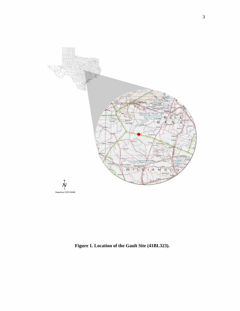
Figure 1. Location of the Gault Site (41BL323). ............................................................ 3
Figure 2. Geologic Profile. .............................................................................................. 5
Figure 3. Tabular Forms of Gault Chert........................................................................ 28
Figure 4. Stream Cobbles of Gault Chert. ..................................................................... 29
Figure 5. Overshot Flakes. ............................................................................................ 33
Figure 6. Refitted Partial Overshot Flakes. . ................................................................. 36
Figure 7. Large Flake. .................................................................................................. 37
Figure 8. Overshot Flake with Corner Removal Blade Scars. ...................................... 39
Figure 9. Alternate Blank Forms................................................................................... 41
Figure 10. Stage II Bifaces. ........................................................................................... 44
Figure 11. Stage III Bifaces........................................................................................... 51
Figure 12. Stage III Bifaces with End Thinning. .......................................................... 52
Figure 13. Stage IV Bifaces. ......................................................................................... 61
Figure 14. Stage V Bifaces............................................................................................ 66
Figure 15. Stage VI Bifaces. ....................................................................................... 70
Figure 16. Stage VII Finished Points ........................................................................... 77
Figure 17. Bifacial Cores. ............................................................................................. 84
Figure 18. Hammerstone/Gouge. .................................................................................. 91
Figure 19. Problem Removal Flakes…………………………………………….….…93
ix
Page
Figure 20. Sequent Flakes. ............................................................................................ 96
Figure 21. Sequent Flakes II. ........................................................................................ 97
Figure 22. End Thinning Flakes. ................................................................................. 106
Figure 23. BladeTypes. .............................................................................................. 139
Figure 24. Blade Ventral Characteristics. ................................................................... 140
Figure 25. Blade Cross-Sections and Lateral Profiles................................................. 144
Figure 26. Dorsal Surface Scar Patterns...................................................................... 145
Figure 27. Blade Termination and Shape.................................................................... 146
Figure 28. Blade Measurement an Calculation Points. ............................................... 148
Figure 29. Primary Blades........................................................................................... 151
Figure 30. Secondary Blades....................................................................................... 159
Figure 31. Corner/Side Removal Secondary Blades. .................................................. 167
Figure 32. Interior Blades............................................................................................ 175
Figure 33. Crested Blades. .......................................................................................... 185
Figure 34. Conical Cores............................................................................................. 193
Figure 35. Conical Core Blade Manufacture Sequence…….……..…………………194
Figure 36. Wedge-Shaped Core (Unidirectional). ...................................................... 198
Figure 37. Wedge-Shaped Core (Bi-directional). ....................................................... 199
Figure 38. Wedge-Shaped Core (Multi-directional). .................................................. 200
Figure 39. Wedge-Shaped Core Blade Manufacture Sequence. ................................. 201
Figure 40. Bifacial Core Tool. .................................................................................... 207
x
Page
Figure 41. Tested Cobbles........................................................................................... 208
Figure 42. Core Tab (a and b) Conical (c and d) Wedge. ........................................... 210
Figure 43. Core Tab Removal Sequence..................................................................... 212
Figure 44. Core Tab (Partial). .................................................................................... 213
Figure 45. Sequent Flake Sequence. ........................................................................... 218
Figure 46. Refit 1. ....................................................................................................... 221
Figure 47. Refit 2. ....................................................................................................... 224
Figure 48. Refit 3. ....................................................................................................... 226

1
CHAPTER I
INTRODUCTION
Archaeological sites containing abundant isolated Clovis-aged materials are rare.
Recently, one such site located in southern Bell County was excavated. This site, known
as the Gault site (41BL323), was extensively investigated during the summers of 2000
and 2001 by several teams under the direction of Texas A&M University (TAMU) and
The University of Texas at Austin (UT). Initially, the archaeological division of UT,
located at the Texas Archeological Research Laboratory (TARL) on the UT campus was
given permission for a three year excavation at this site by the landowners, Rickey and
Howard Lindsey. This work was performed under the direction of Michael B. Collins and
Thomas R. Hester. Harry J. Shafer and Michael R. Waters of TAMU were invited to be
co-directors of the excavation. The excavations consisted of two field schools and were
concentrated in an area dubbed the “Lindsey Pit" in honor of the landowners who first
encountered the Clovis materials. The excavations by UT archaeologists were spread out
at various locations over the site and continued for a year after work by TAMU ceased.
This dissertation presents the results of a technological analysis of the bifaces, blades,
cores, and selected debitage recovered from the Clovis levels at the Gault site. The
primary objectives of the study are (1) to determine those methods employed in the
manufacture of bifaces beginning with the acquisition of the raw material to the finished
form; (2) to determine the process of blade production through a study of the cores, core
This dissertation follows the style of American Antiquity.
2
preparation, as well as the recovered blades; and (3) to evaluate what role the local raw
material types and forms may have played in directing the reduction and manufacturing
strategies employed in biface and blade manufacture.
The Gault Site
The Gault site is located in southwestern Bell County near the Williamson-Bell
County line in central Texas (Figure 1). The site lies within a small valley encompassing
approximately 140,000 square meters that borders both sides of the headwaters of
Buttermilk Creek. Much of the site is clustered around a number of springs situated near
the creek’s headwaters and it is surrounded by low bluffs and hills composed of
limestone. One of the varieties of Edwards chert is abundant on the slopes and tops of the
bluffs and hills. This chert is often of excellent quality and exists in the form of tabular
chunks and nodules. During Paleoindian through Late Prehistoric periods of Texas
prehistory, people were attracted to the site because of the combination of dependable
water and regional plant and animal resources.
In 2000, archaeologists from TAMU and UT conducted the first of two field
seasons at the site. These field schools concentrated on a series of units that had been
previously excavated by the UT under the direction of Michael B. Collins in 1998 and
1999. The 2000 field school excavation was located approximately 150 yards
downstream from the creek’s headwaters. This area is adjacent to the eastern slope of
the valley and is about 75 yards from where Buttermilk Creek makes an eastern turn and
parallels the main midden area of the site.
3
Figure 1. Location of the Gault Site (41BL323).
4
The excavation area was first opened by the Lindsey’s who began digging for
“arrowheads” by utilizing a Bobcat in an attempt to speed up their digging activities.
During this procedure, they encountered a mammoth mandible in association with a
number of lithic artifacts. Thinking this would be interesting to the archaeological
community, they brought these finds to the attention of Michael B. Collins at UT. This
prompted his 1998 and 1999 excavations of the area, which became known as the
“Lindsey Pit.”
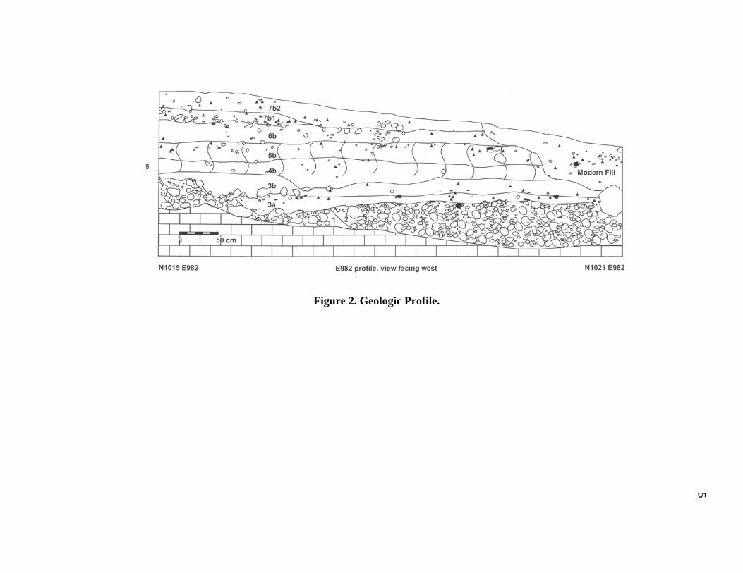
The Clovis material occurs within two geological units (Figure 2). These are
Clovis soil (Geologic Unit 3a) and Clovis clay (Geologic Unit 3b). Over time, these
units were sealed by overburden soils that effectively isolated the Clovis materials
from subsequent mixing. Geologic units 3a and 3b overlay two older units (Geologic
Unit 1 and Geologic Unit 2) formed by colluvial soils. Geologic Unit 1 is the oldest
such unit and consists of limestone gravels originating from the slope. Geologic Unit 2
consists of a cherty gravel alluvium from Buttermilk Creek. These gravels formed from
various types of chert that originated on the slopes and later gravitated into the stream
system. The Clovis clay overlays both of these units, but the Clovis soil only comes
into contact with Geologic Unit 1 near the base of the slope. Clovis technology has
been discussed by many individuals (Bradley 1982; Callahan 1979; Collins 1999a, 1999b;
Frison and Bradley 1999; Gramley 1995; MacDonald 1968; Painter 1965, 1974; and
Sanders 1990), and their work has added greatly to our present knowledge of Clovis lithic
technology. However, as new sites are discovered, it is not improbable that new ideas
could yet be
5
Figure 2. Geologic Profile.
6
developed. The large amount of Clovis artifacts recovered from Gault is unlike any
assemblage recovered thus far. This site was used as a primary quarry and lithic workshop
in which large numbers of artifacts, such as projectile points, blades, and other tool forms
were made. Because of the large amount of reductive debris (cores, failures, and
exhausted tools), this assemblage is ideal for a technological study. Therefore, a study
centered on a technological analysis of biface and blade manufacture at Gault should add
greatly to our understanding of Clovis lithic technology.
As mentioned above, Clovis technology has been the subject of a number of
studies. These studies were based on assemblages ranging from individual projectile
points (isolated finds) to large occupational areas, mostly multi-component sites. Since
many of these studies were conducted on small, mixed, or often-questionable Clovis
assemblages, a number of differing views concerning Clovis technology have been
developed. In some cases, it was believed that a particular conclusion was considered
universal within Clovis technology. Floyd Painter (1965, 1974), for example, constructed
a model of the fluting process at the Williamson site in Virginia that involved the use of
an anvil to support the blank from which multiple flutes were removed via indirect
percussion. According to Painter, this was how all classic Clovis or Clovis-like points
were manufactured and fluted.
Currently, researchers are beginning to realize that Clovis knappers were more
flexible in the strategies employed for point and tool manufacture than previously
accepted (Patten 1999:93). This has led to a number of ideas and models proposed for
Clovis point and/or tool manufacture. Michael B. Collins (1998:138; 1999a:46), for
7
example, suggests that biface reduction was performed on large blade-like flakes and
cores. Collins theorizes that initially only a few flakes were removed via hard hammer
percussion. These flakes were generally large, often terminating in overshot flakes.
Platforms were prepared by the rough beveling of an edge with edge grinding increasing
as thinning progressed. This same beveling procedure was performed for setting up the
base for basal fluting. Final thinning was accomplished through soft hammer percussion.
This theory is typical of many current views; however, others see variations in the
process of manufacturing projectile points. For example, some (including Collins) believe
that overshot terminations were a primary reduction technique, especially in later stages.
Bruce Bradley (1982:203-208) describes a method for Clovis biface manufacture utilizing
overshot terminations which he calls "alternating opposed biface thinning." This
technique is performed by removing a flake first from one margin near either end and then
alternating the next removal from the opposite margin on the same face. Subsequently, the
biface was turned over and the remaining flakes removed from that face also alternating
each margin. Bradley believes that overshot flaking will substantially thin a biface rapidly
with few problems. Also, he has refined this method and has recently stated that as few as
four overshot removals would be sufficient to thin a biface (Bruce Bradley, personal
communication 2000). Others, however, believe that overshot terminations are too
difficult to accurately control and therefore are nothing more than a failed removal.
Callahan (1979:109,111) discovered from experimental replications that overshot
terminations frequently occur as a result of placing the platform too far below the median
line and striking too far inward combined with excessive force and inadequate support.
8
Thus, he concluded overshots were the result of failure and represent unsuccessful
thinning.
At the Adams site in Kentucky, Thomas Sanders (1990:34-37,40,45-47) found a
flaked stone manufacturing site, evidence that supports Callahan's ideas. Based on an
examination of numerous bifaces from the Adams site, Sanders discovered that overshot
terminations were one of the factors causing biface failures. He noted that overshot
numbers were not particularly high, but were constant during all reduction stages. This
accounted for no more than 17% of the unsuccessful executions in any given stage
(Sanders 1990:65).
If overshot terminations are not an intentional strategy, then why are they so
prominent in the manufacture of bifaces? The answer may lie in the idea that Clovis
knappers were intent on a quick reduction and that this was most easily accomplished
through large, often thick flake removals. In removing such flakes, large platforms set low
on the edge are struck with considerable force. Such a removal strategy can easily result
in mistakes. Bob Patten (1999:93-94) describes a method of Clovis reduction that
involves the removal of large flakes across the face of a blank which terminate near the
opposite edge. Realizing possible problems in this method, he cautions that one should
take special precautions to prevent overshot terminations from occurring while removing
these large flakes. Like Bradley, Patten also feels that as few as three or four large flakes
removed from each face are all that may be required to produce a flat even surface.
In reviewing the various Clovis reductive models, it appears that most researchers
tend to agree that rapid reduction occurred with large flake removals. Therefore, if not
9
properly accomplished, as Patten warns, the attempt to produce these flakes could easily
result in an overshot termination. Thus, the result would be that a number of overshot
flakes could be produced which would accumulate within the manufacturing debris. If the
workshop was utilized for extended periods of time, large numbers of overshots could
accumulate, and as such, be easily interpreted as the result of an intentional strategy.
Another issue that is often discussed involves the fluting process. Most
researchers describe fluting as occurring during the final basal thinning process. However,
an alternate view has been proposed by Callahan (1979) that involves a series of flute or
channel flakes that are removed from either end of a biface during the various stages of
reduction, a process he terms “end thinning.” Others have noted this strategy within
archaeological contexts. Sanders (1990:33-41) noted this strategy on his Stage II-IV
bifaces from the Adams site. Some bifaces having end thinning scars were also recovered
from the Thedford II site along with three end thinning flakes (Deller and Ellis 1992:29).
As mentioned above, most views tend to restrict fluting only to basal thinning and
preparation (Bradley 1982; Collins 1998:138; 1999a:46; Ellis and Deller 2000:6; Patten
1999; Witthoft 1952:12). Some (Ellis and Deller 2000:79: Witthoft 1952:12; Sanders
1990:25) describe a strategy involving multiple flute removals from the base that serve as
"guide flakes" for the final flute or channel flake removal. The preparation of platforms
for the final flute removal also vary. The prepared platforms vary, ranging from little
more than a simple rounded edge, a beveled edge, to one with a carefully prepared nipple
(Sanders 1990:25).
10
Views on the initial blank manufacture and selection also vary. As previously
stated, Collins (1999a) describes initial blanks as being either large blade-like flakes or
cores. At the Gault site, large blade-like flakes were being removed, but some very large
thick flakes were also recovered that could also easily serve as biface blanks. At the
Parkhill site in Ontario, large blades were removed from thick blocks of chert that served
as blanks for fluted points (Ellis and Deller 2000:48-49). A similar strategy was also
described at the Shoop site in Pennsylvania (Witthoft 1952:29).
The strategy of blank selection or production may be dependant upon material
type and form. For example, the large blade removals noted at the Parkhill site may be the
most effective method of blank production in dealing with large, thick, blocks of chert.
However, thinner chert tabs or chert having excellent flaking qualities may be best
reduced by bifacial reduction via large thinning flakes. It may be more difficult to remove
large flakes from varieties of chert having poor flaking qualities, thus requiring the use of
an alternate strategy. Bradley (1982:207), for example, describes such a method he calls
“opposed diving biface thinning.” This method involves the purposeful flaking from one
edge that terminates at mid-line in a purposeful hinge. These hinges are subsequently
removed from the opposite edge. It is also well known that gravels often require different
reduction methods, at least during initial preparation. Therefore, the type of raw material
could easily have a significant role in which Clovis reduction strategy is employed.
Another reduction strategy involves the production of blades. Blades are an
accepted component of most Clovis assemblages. However, it is obvious from studies of
Clovis technology that the strategy of blade manufacture is not just restricted to primary
11
blade production, but was also applied in other reductive tasks such as end thinning,
fluting, and initial blank production.
Although blades are considered a part of the Clovis lithic technology, their
occurrence varies. They are more common in the South and Southeast, virtually absent in
the northeast, and scarce in the western portions of the United States (Collins 1999a:4).
The most inclusive study of Clovis blades was conducted by Collins (1999a). For this
study, he reviewed data from 42 sites and concluded that the principal attributes of Clovis
blades are minute platforms, almost no bulbs, minimal ripple marks on the interior
surface, and a strong curvature.
Blades were removed from two types of cores; the conical-type and the wedge-
type. At the time of the publication of his book, Collins felt that the most common form
(from the Gault site) was the conical type. These have platforms that are oriented at right
angles to the long axis of the core. Successive blade removals were performed around the
circumference of the core, thus giving them the conical appearance. The platform angles
produced by these removals average between 60Ε and 70Ε (Collins 1999a:51).
Wedge-shaped cores, however, have an acute angle between the platform and core
face. They have a more narrow face due to the use of thinner or more irregular chert tabs.
The platforms are multifaceted and are prepared by trimming an acute, bifacial edge. In
addition, blades may be removed from opposing platforms (Collins 1999a:51). Collins
also believes that the blades were removed primarily by either indirect percussion or soft
hammer, especially from the conical type.

12
Clearly, many studies of Clovis lithic technology have been conducted at a
number of sites in North America. These studies have resulted in the development of
many opinions and ideas concerning the manufacture of Clovis bifaces and blades.
However, the sheer size of the assemblage recovered and the fact that the layers
containing Clovis artifacts were sealed and isolated from later occupations, offer an
opportunity to produce a clear picture of Clovis technology, at least within central Texas
if not the Central Plains. It should be stressed that the direction of the analysis was not
designed to simply refute or agree with current views, but to ascertain how and to what
extent any particular reductive strategy was applied at Gault. Thus, the findings presented
in the following paper not only substantiate some current views, but also present a number
of previously unknown strategies.
13
CHAPTER II
BIFACE REDUCTION
Bifaces, regardless of culture, constitute one of the more informative artifact
categories available for understanding manufacturing sequences, techniques, and the
use context of stone tools. Within the framework of bifacial technology are a host of
multi-functional forms that range from crude expedient types to finely crafted
examples. These forms are not only made from a single bifacial reduction sequence.
Bifacial fragments are from flakes that have been removed and modified for an
immediate need. Thus, bifaces serve in three primary roles: as cores, providing an
efficient raw material source for flakes having multiple useful edges, as tools
constructed for a long use-life based on resharpenable edges, and as tools shaped for
preexisting hafts (Kelly 1988:719). Considerations for biface production, therefore,
should include the following factors. These are raw material availability, material
versatility and flexibility for tool use and manufacture; time constraints for material
acquisition, and tool manufacture and portability for mobile groups (Hayden et al.
1996:10). Keeping such thoughts in mind, past cultures adapted these considerations to
their specific cultural constraints and needs. This creates specific changes over time
and regional variation.
Stone tools accumulate on sites due to discards that result from manufacturing
failures, caching activities, artifact loss, and intentional discards resulting from normal
tool use. As a result, many of these tools are left in varying states of manufacture and
14
use enabling researchers to reconstruct individual manufacturing strategies, sequences,
and use-life histories of these tools.
Conclusions derived from such studies are often based on single or
multicomponent sites that often contain varying amounts of artifactual materials, rely
on comparisons of sites having regional affinities or (occasionally) from isolated finds.
A clear picture of specific cultural sequences and attributes, especially in
multicomponent sites, are often "clouded" due to problems resulting from a lack of
artifacts and/or bio-turbational and natural activities. As a result, many of the
technological trends currently accepted for specific cultures are based on small,
widespread, and sometimes vague samples. As new sites are found and excavated,
many of the older ideas are refined or dismissed. The Clovis assemblage from Gault is
unique in that it was sealed by sediments that effectively separated it from subsequent
occupations. Therefore, the results of the Gault biface analysis should add significantly
to our current interpretation of Clovis lithic technology.
Clovis Biface Technology
Over the past 40 years, a number of Clovis sites and artifact assemblages have
been reported giving us the basis for much of our current knowledge on Clovis
technology (Butler 1963; Ferring 2001; Gramley 1993; Mehringer 1988; Woods and
Titmus (1985); Wilke, Flenniken, and Ozbun 1991). Clovis lithic technology is
currently described as being a consistent widespread pattern that contains some
regional variations, generally noted in projectile point form (Collins 1999a:45,
1999b:14-21; Kooyman 2000:108-109; Frison and Todd 1986:91-114; Morrow and
15
Morrow 2002:315-319; Stanford 2000:5-10; Willig 1991:92-93;). However, a literature
review of Clovis lithic technology reveals that, in addition to projectile point form
variations, there have been a number of different models proposed for biface reduction
(Bradley 1982:203-208, 1991:369-371; Callahan 1979; Sanders 1990). Like projectile
point variation, most of these models are regional differences that vary with material
selection and blank production (Whitthoft 1952:464-495; Painter 1965:12, 1974:24-32;
Bradley 1982:203-208; Collins 1999a:46; Deller and Ellis 1992:13-24; Ellis and Deller
2000:47-66).
Some of these variations are attributed to regional material types and/or forms
having morphological constraints that only allow for specific type blanks to be
produced or require alternate strategies for blank thinning (Bradley 1982:203-208,
1991:369-374; Sanders 1990:31-49) and final fluting methods (Witthoft 1952:464-495;
Painter 1965:12-16, 1974:24-32; Kraft 1973; Bradley 1982, 1991; Sanders 1990;
Storck 1997). Although material variation is not the only reason for creating
technological changes within a single culture, it is one that can have significant
implications over the direction that individual lithic reduction strategies take.
Currently, there are two primary reductive strategies accepted as part of the
Clovis chipped-stone industry (i.e. bifacial reduction and prismatic blade production)
(Sanders 1990, Boldurian and Cotter 1999; Collins 1999a, Kooyman 2000:109). Clovis
tools are described as being made primarily from the byproducts of biface and blade
manufacture (Collins 1999a:45). Usually, these two reductive strategies are considered
as separate strategies. However, as the analysis of the Gault material progressed, it
16
became increasingly clear that many of the techniques employed in blade production
were also utilized in bifacial manufacture.
A new view that is gaining some acceptance is that Clovis knappers were more
flexible in the strategies they employed for projectile point and tool manufacture than
was previously thought (Patten 1999:93). This idea was developed from a number of
models that have been proposed for Clovis reduction strategies that have been derived,
not only from intensive studies of Clovis materials, but also an increased interest in
flintknapping which has enabled some researchers to test these models experimentally.
Reductive Models
One of the more prominent reduction models was developed by Bruce Bradley.
Based on observations made on bifaces from the Anzic (Lahren and Bonnichsen 1974)
and Simon (Butler 1963) sites in Idaho and the San Jon site in New Mexico (Roberts
1942), Bradley noted a patterned sequence of reduction. His ideas were further
reinforced from his analysis of flake debitage from the Sheaman site in eastern
Wyoming. From these, Bradley noted a distinctive flaking process that involved a flake
removal in which flakes were detached completely across the face of the biface ending
in an overshot type termination. Applying this to his skill in flintknapping, he found
this technique to be very effective in the thinning process (Bradley 1982:206-207;
Frison and Bradley 1999:65). This has led many to accept the application of overshot
termination as a primary reduction technique, especially in later stages (Collins
1998:138, 1999a:46; Kooyman 2000:109).
17
Through his observations, Bradley formulated two models: (1) the alternating
opposed biface thinning method and (2) the opposed diving biface thinning method.
The alternating opposed biface thinning method involves initial shaping and thinning
by removing large thinning flakes in a patterned sequence. This begins with the
removal of a large flake from a margin near one end of the biface. This is followed by
the removal of another flake from the opposite margin near the other end of the same
face. The next step is the removal of another flake from the original margin of the same
face but between the first two removals. Additional flakes could then be removed from
the central portion if further thinning is required. Many of these flake removals
terminate in overshot flakes. This same pattern is then repeated on the opposite face
(Bradley 1982:207).
Bradley realized that this pattern was not always followed. Once the biface
became narrow and more regularized, a second method (the opposed diving biface
thinning method) was employed. This method was applied near the end of the thinning
process and allowed for maximum thinning without the danger of overshot
terminations. In this method a sequence of flakes were removed from one margin on
the same face and intentionally terminated in a hinge fracture near the mid-line of the
biface. These hinge terminations were then removed by the removal of a series of
flakes originating from the opposite margin. Problems in regularity increase, however,
as additional flakes are removed from the same face (Bradley 1982:207).
The methods described by Bradley seem to work best when the raw material is
relatively thin, such as small tabs. In addition, Bradley's model obviously does not
18
involve reductive stages other than switching from the alternating opposed biface
thinning technique to the opposed diving biface thinning technique after the biface was
narrowed and regularized (Bradley 1982:207); nor, does he address cortical removal.
This is not surprising as reductive stages can be very subjective and, as such,
may not reflect a true strategy or be the intention of the knapper. Muto (1971), for
example, offered a reductive model he called "blank-preform-product" for Clovis-like
bifaces. The analytic scheme of this model was based on a reductive process that did
not involve specific stages but was dependant upon type of percussor and the
diagnostic attributes of flakes and preforms (Muto 1971:48, 76-83). Regardless of
whether or not the reduction process was an uninterrupted continual process, the
establishment of reductive stages is very helpful in understanding the process of
reduction in an orderly and organized manner. Thus, the idea of recognizing reductive
stages can be very useful when analyzing the manufacturing sequences derived from
thick or chunky forms of raw material.
A model utilizing reductive stages through replication experiments was
developed by Errett Callahan (1979). Callahan's model was developed from his
expertise in flintknapping involving a wide range of materials as well as years of
studying various reductive strategies. The model consists of nine reductive stages.
They begin with (1) obtaining the blank (which consists of the procurement of spalls)
from large cores or the selection of a cobble, nodule, or chunk of material; (2) initial
edging; (3) primary thinning stages; (4) secondary thinning stages; (5) a shaping stage
he terms the "rough perform;” (6-8) three fluting stages which consist of a preparation
19
stage and fluting of each face; and (9) ending with a retouching stage for the final edge
straightening and shaping process of the fluted preform. In addition, he developed
optimal size ratios for spalls and width/thickness ratios for the various reductive stages
(Callahan 1979: 36-37, 154-155).
To many, nine stages seems a little excessive but, in Callahan's defense, he is
describing each step within the process in an explicit manner, such as dividing each
fluting sequence into a preparation stage and two removal stages. In addition, he also
realized that biface reduction may be an uninterrupted continuum from start to finish
with no major shifts in knapping strategy (Callahan 1979:38).
The blanks described in Callahan's model were produced from three material
forms (1) unmodified raw material (utilized as is or split into more usable blanks); (2)
double blanks (split pieces, chunks or nodules, split or sheared cobbles, and split
cores), and (3) block cores defined by Crabtree (1972:20, 39, 55) as being conical,
cylindrical, rectangular, tabular, or polyhedral. Interestingly, Callahan's illustrations
(1979:43) show some of these block cores to closely resemble blade cores, albeit with
wider flake scars than typical blade cores. He terms flakes removed from these cores as
being "blade flakes" which resemble prismatic blades. Similarities include longitudinal
ridges and prepared platforms (near parallel sides) and may be twice as long as wide,
but they are much wider and longer than true blades (Callahan 1979:53). Thinning is
conducted initially by hard hammer followed by soft hammer removals utilizing antler
billets as thinning continues. Throughout the thinning processes, flakes are detached in
lateral removals either across the face of the blank or to approximately midline.
20
However, when hinge or overshot terminations occurred, these were determined to be
mistakes or failures rather than a purposeful intent incorporated into the thinning
process (Callahan 1979:84-86, 108-112,). In addition, a process termed "end thinning,"
which flakes, that were often long and blade-like, were removed from both the
proximal and distal ends throughout the thinning stages, was practiced. Flakes removed
in this end thinning process also often failed in plunging or deep hinge type
terminations. Pressure flaking was utilized in some edge straightening/thinning,
platform preparation and final shaping processes and indirect percussion was
preformed in some of the end thinning removals (Callahan 1979:83-153).
Although Callahan's model is based on his observations from fluted point sites,
such as the Williamson and Flint Run sites, the Cattail Fluting Tradition developed by
Floyd Painter (1970), and his replication experiments, it was not applied to any
particular site. However, it was utilized in a recent study of the Adams site, an
excellent Clovis manufacturing site in Christian County, Kentucky (Sanders 1990).
Although based on Callahan, Sanders condensed Callahan's nine reductive stages to
seven with Stages 0 to 5 being equivalent to Callahan, and Stage 6 condensed from
Callahan's stages 6 to 9. Since Callahan did not address finished points, Sanders
included a seventh stage that would represent finished points (Sanders 1990:22-23).
Although not found on the site proper, the raw material utilized at the Adams
site was Genevieve chert that occurred in the form of nodules and tabular chunks.
Cores are represented by a variety of forms which include block cores, spherical cores,
biface cores, and miscellaneous core fragments thought to be shattered nodules. Similar
21
thinning strategies to Callahan's model involving both lateral and end thinning
processes were also noted in the Adams stages 2 through 4. Rejections and failures
were attributed to step fractures, deeply hinged and overshot terminations, as well as
some material flaws (Sanders 1990:33-44).
Fluting
Flutes are the single most recognizable diagnostic attribute of Paleoindian
fluted point complexes. The process of fluting has been one of a great deal of study,
both from actual archaeological materials and from experimental replications. As a
result, numerous models have been developed.
One of the earliest models was the "Enterline" technique (Whitthoft 1952:475,
481-483) in which lateral flakes were removed from either side of the primary channel
flake that served both as "guide" flakes for the removal of the central channel flake and
to further thin the basal end. This technique was noted at the Adams site (Sanders
1990:4567), although considered rare, as well as at other functionally similar
Paleoindian sites such as the Williamson site in Dinwiddie County, Virginia (McCary
1975:60-61, 77).
Another technique describing the fluting process was described by Floyd
Painter (1974). This technique, called the “Cattail Creek Fluting Tradition,” was
developed from a Clovis-like fluted point site in Dinwiddie County, Virginia. The
technique is characterized by placing a preformed blank flat over the edge of an anvil
of wood or stone with the basal end projecting approximately one-quarter of an inch
over the edge. A sharp blow from a hammerstone was applied snapping off a small
22
section of the basal end that was often a perfect 90Ε or sometimes snapping off a short
hinge or flute on the opposite face from the blow. The break would occasionally snap
off an inch or so from the edge severely shortening the blank. Painter (1974:24) noted
such snapped-off bases present at the Williamson site.
The blank was then set upright on the anvil and a flute struck off by means of a
punch held at or very near the center of the base. A second flute was removed from the
opposite face if enough of the platform remained; otherwise, a new platform was
prepared. The flutes removed often resembled a bottle shape in outline. When this
occurred, small flutes were removed from each side of the central flute. After the initial
fluting sequence, both faces of the blank were percussion flaked to further thin the
blank. This obliterated all previous flake scars. At this stage, if it was thought to be too
thick in the middle, it was again placed over the anvil, the basal edge was snapped off
again, and the fluting process was again repeated (Painter 1974:24-28).
Although both the Enterline and the Cattail Creek Fluting techniques have been
noted at several eastern Clovis and Paleoindian sites, a number of other techniques for
preparing the basal edge for fluting have also been described. For example, at the
Adams site, Sanders (1990:64) describes several techniques that include the formation
of slight to well defined projections or nipples at or near the center of a beveled basal
edge, fluting from a wedge-shaped base, or an unmodified, slightly convex base.
Occasionally, multiple flutes from one or both faces were noted. It was determined
that, in some cases, indirect percussion was utilized; however, the most common
technique was determined to be by direct percussion.
23
McCary (1975:61-67) describes four techniques for preparing the basal edge
and striking platform from the Williamson site. These are:
1. The technique for forming the striking platform in this method is equivalent to
Whitthoft's Enterline technique.
2. The platform was prepared by simply removing a slightly beveled flake
transversely across the base and grinding the entire edge. A punch for the flute
removal could be placed at any point near the center of the edge.
3. The striking platform in this method was made by removing two transverse flakes
from each end of the obverse face with the juncture forming the striking platform.
On the reverse face two lateral flakes were removed that isolated the central flute.
4. The striking platform in this method was prepared on an oval or straight base by
removing a series of small, slightly beveled flakes along the entire basal edge
which was subsequently ground. A flute was removed by placing a punch at the
juncture at or near the center of the edge of any two of these flakes. Fluting the
reverse side was accomplished by forming a projection or semi-nipple in the
approximate middle of the edge. This projection could be further isolated by
removing a small guide flakes adjacent to and angling away from each side of the
projection.
A method termed "piggy-back fluting" from New Jersey (Mounier et al.
1993:16-20) begins with a biface formed with a flat or lenticular surface on one face
and a ridged or angular face on the other with nipples (for each face) that have been
24
isolated and ground. A single flake is removed from the flat face and multiple
superimposed flakes (primary and secondary) are removed from the ridged face.
The discussion on fluting techniques was presented to emphasize that a wide
range of fluting strategies exist within fluted point industries. Although these examples
are all from the eastern Paleoindian and Clovis industries, the primary difference
between Eastern and Western Clovis styles is within the length and width of the flute.
Long fluting scars similar to Folsom flutes are indicative of the Eastern tradition, while
the flutes on Western Clovis are shorter (Patten 1999:94).
Sanders (1990:68) argued that even though the basic fluting techniques seen
within Eastern Paleoindian assemblages are technologically similar, when large
assemblages occur, a range of fluting techniques is evident. Sanders explains that even
though Clovis knappers, such as those at the Adams site, were working under their own
particular cultural tradition, they were aware of a wide range of fluting techniques from
which individual knappers could utilize, on an as needed basis, to overcome some of
the technological difficulties presented by individual preforms. This argument can also
be used in understanding Clovis biface reduction strategies. The earlier discussion of
biface reduction reviewed several of the more prominent reduction technique, such as
Bradley's alternating opposed biface thinning and opposed diving face techniques and
Callahan's multiple stage reduction sequence incorporating end thinning and overface
flake removals that are presently considered relevant within Clovis lithic technology. It
can, therefore, be argued here that Clovis knappers were also aware of a number of
reduction techniques which could be applied in biface reduction and, like the variations
25
in fluting techniques, were utilized on an as needed basis. The specific technique
chosen would be dependant on a number of different factors that include material type
and form or from difficulties that often occur during the manufacturing process.
Gault Bifaces
In all, four finished projectile points (three complete and one basal half) and 55
bifaces in varying stages of manufacture were recovered. Fourteen of the bifaces are
whole (four were refitted from broken specimens forming two complete specimens)
and 38 are fragmented.
Unless otherwise noted, all specimens utilized in this study were recovered
from the Clovis soil or Clovis clay geologic units. The majority of the bifaces (N = 33)
and finished points (N = 3) were found within the Clovis clay (Geologic Unit 3a)
(Appendix A, Table 1). Twelve additional specimens were recovered from units where
the Clovis clay and Clovis soil (geologic units 3a and 3b) were indistinguishable during
excavation. These artifacts came from either geologic units 3a or 3b, but specifically
where, cannot be established with absolute certainty. Ten bifaces and the fourth
finished point were recovered from the Clovis soil (Geologic Unit 3b).
The method for assigning reduction stages to the Gault bifaces will basically
follow the reductive sequence used by Sanders (1990:23) for the Adams site. Sanders'
sequence was modified from Callahan's (1979) model that included a procurement
stage and nine reductive stages. Because Callahan's model deals primarily with the
reductive stages prior to fluting, Sanders felt it necessary to adapt his model to include
26
the small number of fluted specimens recovered at the Adams site. In addition, Sanders
collapsed three of Callahan's stages into one. These stages are as follows:
Stage 0. Procurement
Stage I. Obtaining the Blank
Stage II. Initial Edging of the Blank
Stage III. Primary Thinning of the Blank
Stage IV. Secondary Thinning of the Blank
Stage V. Final Shaping of the Preform
Stage VI. Fluting and Finishing the Point
Stage VII. The Finished Clovis Point.
Rather than define each of the individual stages utilized in this report here, the
definitions of each will be included within the following discussion in the analysis
section below.
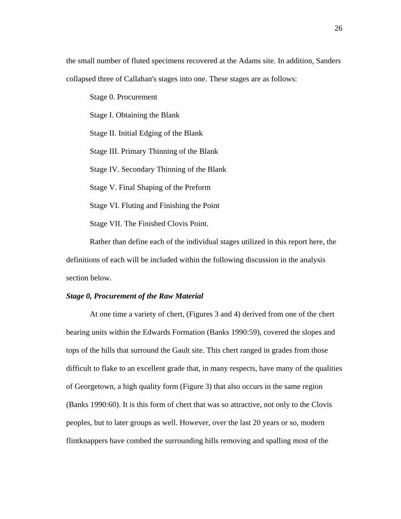
Stage 0, Procurement of the Raw Material
At one time a variety of chert, (Figures 3 and 4) derived from one of the chert
bearing units within the Edwards Formation (Banks 1990:59), covered the slopes and
tops of the hills that surround the Gault site. This chert ranged in grades from those
difficult to flake to an excellent grade that, in many respects, have many of the qualities
of Georgetown, a high quality form (Figure 3) that also occurs in the same region
(Banks 1990:60). It is this form of chert that was so attractive, not only to the Clovis
peoples, but to later groups as well. However, over the last 20 years or so, modern
flintknappers have combed the surrounding hills removing and spalling most of the
27
better grade chert. Today, there is little, if any, of this chert left in an unaltered form on
the site, other than thousands of flakes and small chunks left from their spalling
activities. Fortunately, a survey of some of the surrounding region revealed that this
chert also occurred in the near vicinity of Gault from which a small sample was
obtained.
Most of the artifacts recovered from the Clovis layers of the site have been
stained an orange-brown to (in some cases) a greenish-brown color from dissolved
minerals present within the deep groundwaters of the creek. This staining is so
prominent that it became a marker for chert found in most of the Clovis levels. It was
through recently broken and damaged artifacts and pieces of chert that identification of
the specific type of chert was made.
The high grade form is an opaque light to dark gray (Munsell 10YR5/1) chert
that occurred mostly in thick rectangular tabs having square to occasional rounded
edges. Most of the lateral edges represent old breaks created from pressures exerted
from overburden deposits on the original chert layers before the chert weathered out.
This chert originally formed as large plate or pancake-like tabs, thicker in the middle
and rounded on their edges, within large seams of the local limestone. Overburden
pressures caused these large tabs to fracture into various sized square to rectangular
shaped chunks. Thus, chunks originating from the interior portions of the parent tab
will have vertical or "square" edges, while those from near the edge will have one or
more edges that are rounded and covered with typical cortex. Over time, the square
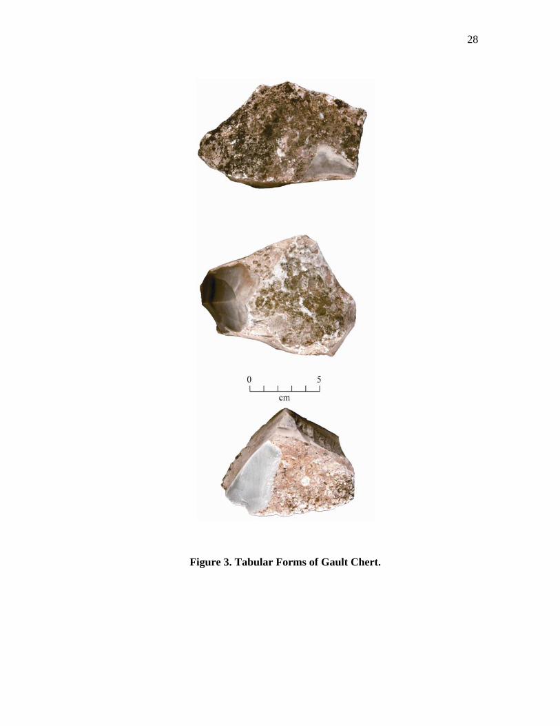
28
Figure 3. Tabular Forms of Gault Chert.
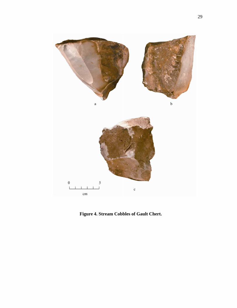
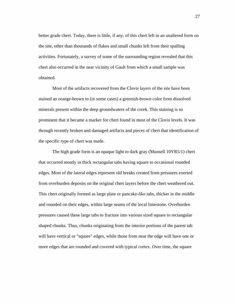
29
Figure 4. Stream Cobbles of Gault Chert.
30
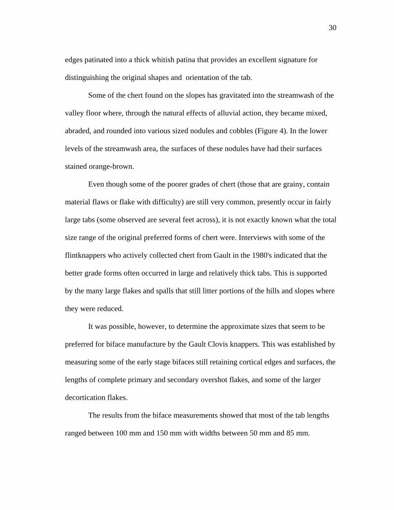
edges patinated into a thick whitish patina that provides an excellent signature for
distinguishing the original shapes and orientation of the tab.
Some of the chert found on the slopes has gravitated into the streamwash of the
valley floor where, through the natural effects of alluvial action, they became mixed,
abraded, and rounded into various sized nodules and cobbles (Figure 4). In the lower
levels of the streamwash area, the surfaces of these nodules have had their surfaces
stained orange-brown.
Even though some of the poorer grades of chert (those that are grainy, contain
material flaws or flake with difficulty) are still very common, presently occur in fairly
large tabs (some observed are several feet across), it is not exactly known what the total
size range of the original preferred forms of chert were. Interviews with some of the
flintknappers who actively collected chert from Gault in the 1980's indicated that the
better grade forms often occurred in large and relatively thick tabs. This is supported
by the many large flakes and spalls that still litter portions of the hills and slopes where
they were reduced.
It was possible, however, to determine the approximate sizes that seem to be
preferred for biface manufacture by the Gault Clovis knappers. This was established by
measuring some of the early stage bifaces still retaining cortical edges and surfaces, the
lengths of complete primary and secondary overshot flakes, and some of the larger
decortication flakes.
The results from the biface measurements showed that most of the tab lengths
ranged between 100 mm and 150 mm with widths between 50 mm and 85 mm.
31
However, some of the overshot and large flake widths were in the 140 mm and 150
mm range, suggesting that larger bifaces were also made. Although, none of these large
bifaces were recovered by TAMU archaeologists, one was noted in the UT collection
from Gault.
Tab thickness was more difficult to ascertain as none of the early stage bifaces
have cortex on both faces. The thickest biface measured was 48 mm thick, with most
between 20 mm and 25 mm. Some of the knappable sized samples collected from the
near vicinity were between 50 mm and 55 mm thick. These, however, may represent a
more realistic measurement of the maximum thickness used, thinner tabs would also
have been utilized when found.
Stage I, Obtaining the Blank
A blank is a usable piece of lithic material of an adequate size and form for
making a lithic artifact (Crabtree 1972:42) and occurs as flakes, cobbles, nodules, or
slabs. Blank forms utilized at Gault were made from thin to thick tabular chunks and
nodules of chert, un-modified macroflakes, and blade-flakes. Unfortunately, no definite
examples of Stage I bifaces were identified from the TAMU excavation; however, a
strategy for the initial biface reduction sequence was reconstructed through an analysis
of the large flake debris. The usage of large macroflakes, blades and/or blade-flakes as
blanks is supported by several later stage bifaces that are made on large flakes and
blade-flakes.
As mentioned above, some of the flake debris was used to help reconstruct the
initial reduction sequence. One of the principal flake forms used in this determination
32
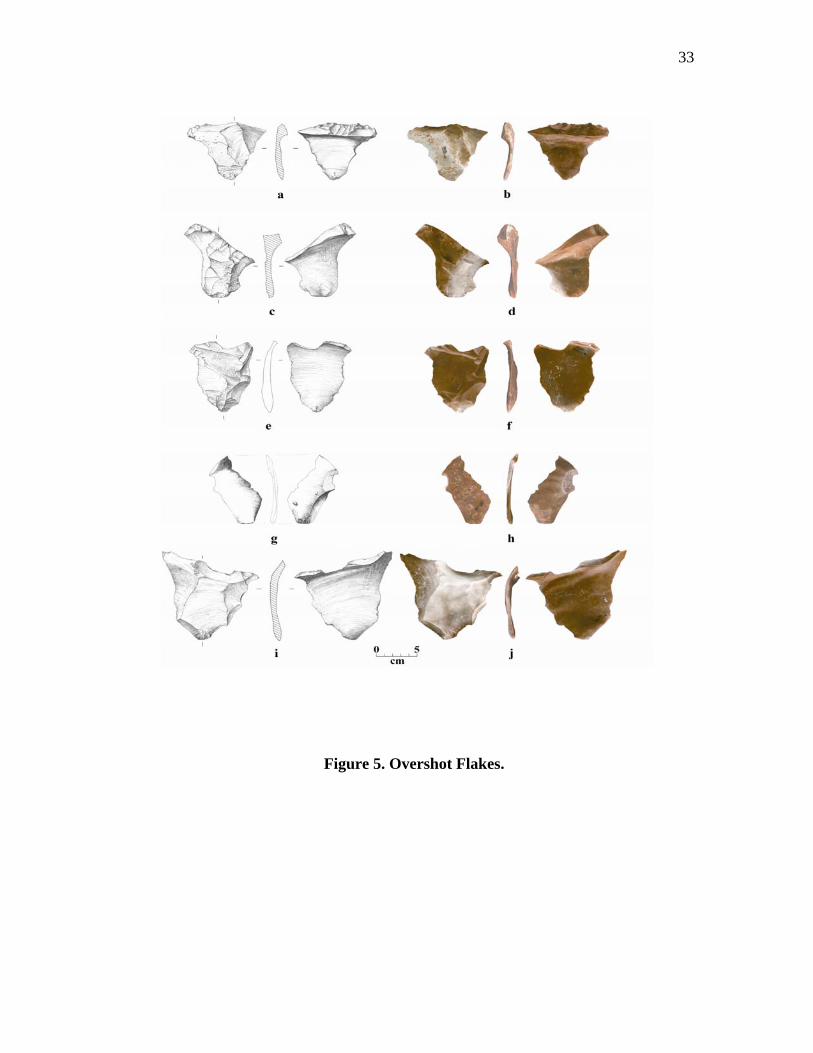
is the overshot flakes (Figure 5). However, before we proceed further, the use of the
term "overshot flake" should be clarified. The definition for an overshot or outrepassé
flake is one that occurs as the force of impact and the resulting crack travels to the end
of the core. Instead of exiting the on the core surface, it bends downward removing part
of the end of the core (Whittaker 1994:19). One usually visualizes this type of
termination as occurring on thinned preforms where both the ventral and dorsal
surfaces have merged into a sharp edge and little or no vertical remnant of the blank's
edge remains.
The same fracture occurs on thick, chunky tabs having square vertical edge.
Rather than plunging completely to the opposite face, the tab's thickness causes the
fracture to terminate at different positions on the vertical lateral edge; thus, removing
only a part of the opposite edge. This type of overshot is termed here as a partial
overshot (Figure 5 e-j). One that, more typically removes both the dorsal and ventral
surfaces is termed a full overshot (Figure 5 a-d). Of the 185 overshot flakes recovered
from Gault, 121 are classed as partial overshots. Twenty-four of the full overshots were
recovered from Geologic Unit 3a, 19 from Geologic Unit 3b, and 3 are from geologic
units 3a or 3b. Sixty-nine partial overshots came from Geologic Unit 3a, 16 from
Geologic Unit 3b, and 12 are either from geologic units 3a or 3b (Appendix A, Table
2). Partial overshots (Appendix A, Table 3) are represented within all three of the flake
categories. These are primary (N = 23), secondary (N = 48), and interior or tertiary (N
= 54). Most of these flakes were removed from across the surface, with some also
retaining one or more ends of the tab. Since many of the interior partial overshots
33
Figure 5. Overshot Flakes.
34
retain heavy patina and/or cortex on one or more of their lateral edges, it is evident that
these flakes continued to be produced even after the cortical surface had been removed.
The idea of continued partial overshot flaking from the lateral edges is
supported by looking at the platform types (Appendix A, Table 4). All three partial
overshot flake types have examples containing both natural and plain type platforms.
Natural platforms are dominant on the primary and secondary overshots while plain
platforms become dominant on the interior overshots. In addition, dihedral and
polyhedral platforms begin to appear on secondary flakes and are equally represented
on the interior flakes. This suggests that, as the lateral removals continue, some
platform modifications of the platform edge became necessary in order to continue
overface flaking. The platform angles also remain essentially constant for all three
flake types with the primary reduction of edge angle occurring between natural and
plain platforms.
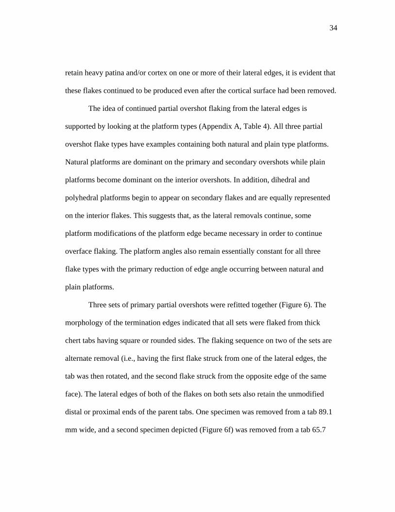
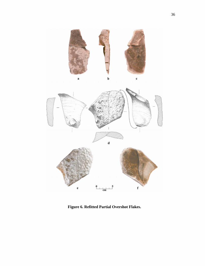
Three sets of primary partial overshots were refitted together (Figure 6). The
morphology of the termination edges indicated that all sets were flaked from thick
chert tabs having square or rounded sides. The flaking sequence on two of the sets are
alternate removal (i.e., having the first flake struck from one of the lateral edges, the
tab was then rotated, and the second flake struck from the opposite edge of the same
face). The lateral edges of both of the flakes on both sets also retain the unmodified
distal or proximal ends of the parent tabs. One specimen was removed from a tab 89.1
mm wide, and a second specimen depicted (Figure 6f) was removed from a tab 65.7
35
mm wide. The last set (Figure 6a) broke in half during detachment and was removed
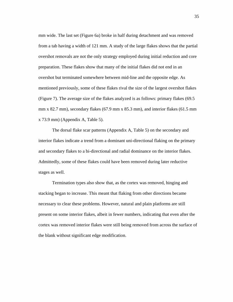
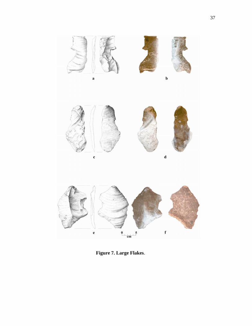
from a tab having a width of 121 mm. A study of the large flakes shows that the partial
overshot removals are not the only strategy employed during initial reduction and core
preparation. These flakes show that many of the initial flakes did not end in an
overshot but terminated somewhere between mid-line and the opposite edge. As
mentioned previously, some of these flakes rival the size of the largest overshot flakes
(Figure 7). The average size of the flakes analyzed is as follows: primary flakes (69.5
mm x 82.7 mm), secondary flakes (67.9 mm x 85.3 mm), and interior flakes (61.5 mm
x 73.9 mm) (Appendix A, Table 5).
The dorsal flake scar patterns (Appendix A, Table 5) on the secondary and
interior flakes indicate a trend from a dominant uni-directional flaking on the primary
and secondary flakes to a bi-directional and radial dominance on the interior flakes.
Admittedly, some of these flakes could have been removed during later reductive
stages as well.
Termination types also show that, as the cortex was removed, hinging and
stacking began to increase. This meant that flaking from other directions became
necessary to clear these problems. However, natural and plain platforms are still
present on some interior flakes, albeit in fewer numbers, indicating that even after the
cortex was removed interior flakes were still being removed from across the surface of
the blank without significant edge modification.
36
Figure 6. Refitted Partial Overshot Flakes.
37
Figure 7. Large Flakes.
38
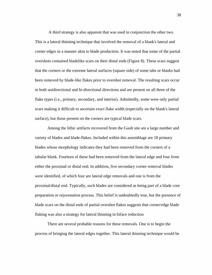
A third strategy is also apparent that was used in conjunction the other two.
This is a lateral thinning technique that involved the removal of a blank's lateral and
corner edges in a manner akin to blade production. It was noted that some of the partial
overshots contained bladelike scars on their distal ends (Figure 8). These scars suggest
that the corners or the extreme lateral surfaces (square side) of some tabs or blanks had
been removed by blade-like flakes prior to overshot removal. The resulting scars occur
in both unidirectional and bi-directional directions and are present on all three of the
flake types (i.e., primary, secondary, and interior). Admittedly, some were only partial
scars making it difficult to ascertain exact flake width (especially on the blank's lateral
surface), but those present on the corners are typical blade scars.
Among the lithic artifacts recovered from the Gault site are a large number and
variety of blades and blade-flakes. Included within this assemblage are 18 primary
blades whose morphology indicates they had been removed from the corners of a
tabular blank. Fourteen of these had been removed from the lateral edge and four from
either the proximal or distal end. In addition, five secondary corner removal blades
were identified, of which four are lateral edge removals and one is from the
proximal/distal end. Typically, such blades are considered as being part of a blade core
preparation or rejuvenation process. This belief is undoubtedly true, but the presence of
blade scars on the distal ends of partial overshot flakes suggests that corner/edge blade
flaking was also a strategy for lateral thinning in biface reduction
There are several probable reasons for these removals. One is to begin the
process of bringing the lateral edges together. This lateral thinning technique would be
39
Figure 8. Overshot Flake with Corner Removal Blade Scars.
40
one of the first steps employed in reducing the sides of thick tabs without removing too
much of the lateral edge. Another reason would be to remove any irregularities or
damage present on a tab's or blank's lateral edges. Besides natural disconformities,
chert exposed on the surface for some time often develops damage resulting from
erosional activities, frost, or fire, that (unless removed) could impede reduction.
A third reason would be to establish a good platform angle. If, for example, one
of the lateral edges along one face of a tab greatly exceeds 90°, it may be necessary to
remove one or more flakes from the edge on the opposite face of the same edge to
create a good platform with a knappable angle less than 90°. Since the average of the
platform angles on the partial overshots ranged between 76° and 82° and on the large
flakes between 76° and 79°, it would not take many removals to obtain these angles.
The last reason may be to establish some contour of the surface along an edge.
Contouring can help guide flake fracture to terminate, either on or near the angled
surface created by the removal or (depending upon the amount of force applied) plunge
into an overshot.
Although more than 100 large flakes were recovered, most are too thin or
contain problems such as humps, hinge terminations, or natural damage to be very
useful in biface reduction. Large macroflake spalls, however, were utilized at Gault, as
there are several examples of later stage bifaces that are flaked on large flake spalls.
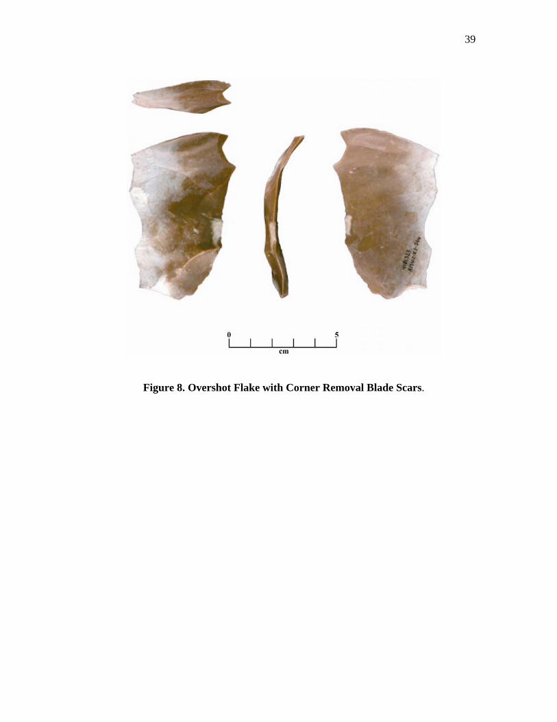
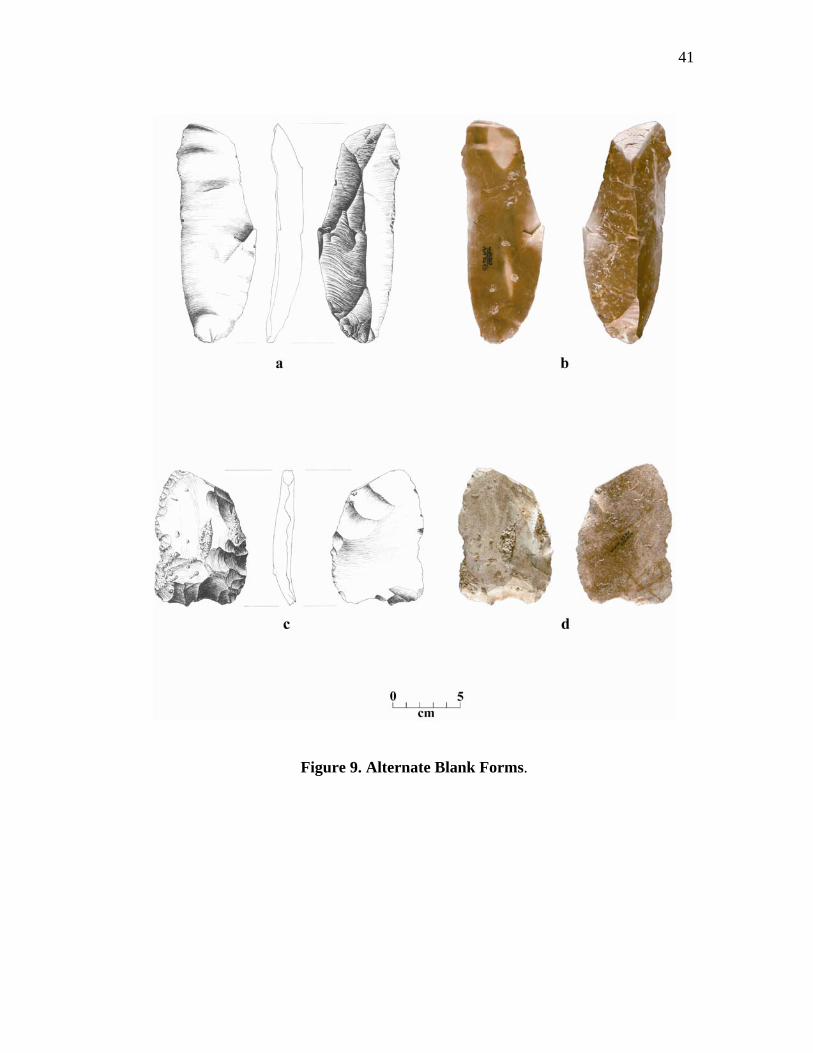
A large blade-like flake (Figure 9a-b) that is of a sufficient size for biface
manufacture does conform nicely with the Stage I blade-like flakes produced by
Callahan (1979:55-56). This specimen is a secondary flake (measuring 164 mm wide
41
Figure 9. Alternate Blank Forms.
42
by 55.6 mm wide) is slightly curved, and has a dorsal scar pattern that is unidirectional
with a prominent central ridge. This particular example has one lateral edge that
contains good use-related wear indicating a probable function in some cutting or
scraping activities, which probably precluded it from being bifacially reduced.
Briefly, the Stage I process began with selecting an unmodified piece of chert.
This chert was either in the form of a thin to thick, roughly rectangular, tab or nodule
from the adjacent hillside exposures or occasionally a cobble from chert deposits
within Buttermilk Creek. A usable blank was initially formed by the removal of most
of the cortex and irregularities from the dorsal and ventral surfaces. These were
removed by large flakes that often plunged over the opposite edge (partial overshot
flake) or terminated on or near the edge of the tab.
Several patterns of flake removal were noted. The first is an alternate removal
pattern where a flake is removed first from one side and the second from the opposite
edge (same face). Flakes removed from the same edge may be in a parallel sequence
or spaced in intervals. A second pattern is a uni-directional sequence where one flake
after the other is removed from same side terminating near or over the opposite edge.
Like the alternate pattern, flake removals were not always next to each other, but were
removed in intervals along the edge. Regardless of the pattern used, flake removals did
not always proceed as planned. This necessitated a third pattern that gradually evolved
from the first two. Due to material faults, misdirected blows, or any number of other
knapping errors, some flakes terminated into deep hinges or stacks. These problems
43
forced the knapper to flake from another direction or angle, in order to "clear" the
problem; thus, creating a random bi-directional and radial pattern.
The vertical edges of these tabs were, most often, covered with a thick patina
rather than cortex which did not impede flake removal or require additional alteration
for a striking platform. However, if the striking angle was excessive or cortex was
present, lateral flaking was necessary to establish a proper angle and/or a usable
platform. In addition, the corners of some tabs were removed using a blading technique
performed to regularize the edge or initializing lateral thinning. Large macroflake
spalls and blade-like flakes were also used as biface blanks. These were probably
selected from flakes produced during the decortication process of the tabs, or (in the
case of blade-like flakes) through a more predetermined strategy of core preparation for
the production large usable spalls.
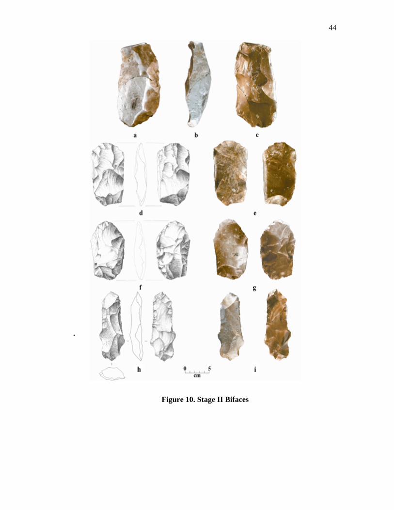
Stage II, Initial Edging (N = 16)
This stage is a continuation of the thinning process with the primary intent to
reduce all edges to a, more or less, sharp and sinuously shaped edge. Seven of the
sixteen specimens are complete (Figures 9c-d, Figure 10), one of which was refitted
together from two pieces. One is made on a large macroflake spall (Figure 9c-d), and
the rest are on thick cores. Of the fractured specimens, only one was too small to
provide any data. Nine were recovered from Geologic Unit 3a, 5 from geologic Unit
3b, and 2 from either geologic units 3a or 3b. Interestingly, one of the refitted
specimens had one piece found in Geologic Unit 3a and the other in Geologic Unit 3b.
44
.
Figure 10. Stage II Bifaces
45
The metrics (Appendix A, Table 6) for the Gault Stage II bifaces are as follows:
the whole specimens averaged 114.1 mm long, 62.6 mm wide, and 21.3 mm thick. A
comparison of these averages (Appendix A, Table 6) with those for the Adams site and
Callahan's replications show that the Gault Stage II bifaces are slightly longer, wider,
and thicker than both the Adams site and Callahan's findings. The width/thickness
ratios for Gault average 2.1:1 (cores only) with ranges of 2.0:1 - 3.1:1 for the cores and
5.0:1 for the flake spall. These ratios fall within the lower portion of Callahan's
optimum range of 2:1 - 3:1 for core reduction with ranges that can be as high as 6:1 for
flake reduction and are only slightly lower than the 2.4:1 ratio for the Adams site. A
natural surface and/or cortex are present on all but five specimens. It is restricted to the
lateral edges of 5 specimens, to the dorsal or ventral surfaces of 5, and to both the
lateral and either the dorsal or ventral surfaces of 2. The flaked surfaces of the Stage II
Bifaces contain large flake scars, some of which are overshot terminations. Most
terminate past the middle or near the opposite edge. The negative bulb scars are deep
with numerous hinge and step fractures present suggesting the use of hard hammer.
Some of the edges on the more "developed" Stage II bifaces have portions that have
had a number of small flakes removed for platform preparation.
The flaking process in Stage II began with a continuation of large flake
removals flaked from the edges of the unmodified square sides. As thinning progressed
and the corners of the dorsal and ventral surfaces approached each other, some portions
of the edges were slightly beveled by small unifacial flake removals. These were flaked
46
as part of the process of setting up striking platforms for thinning or removing
knapping problems.
Partial overshot flakes (N = 5) continue to be removed, but the majority of the
bifaces (N = 10) have flakes that terminate at or slightly over the midline of the biface.
Numerous hinge and step fractures are present, but material flaws such as natural
cracks, inclusions, and potlids from heat and frost fracture account for most of the
failures.
Although, knapping errors such as hinges and stacks appear to be common,
many were successfully removed. Evidence for this was confirmed through a study of a
flake category termed "problem removal flakes". This category (N = 51) is composed
of small to large flakes whose dorsal surfaces contain remnants or complete stacks,
hinges, etc. that were successfully removed from a biface.
End thinning appears at this stage (with seven specimens having removals from
either end, both ends, and/or on both faces). Figure 10a-c shows a refitted example that
fractured during end thinning attempts. Since flakes are usually thickest near the
platform and thin out distally, those flakes that terminate near the mid-line of the
biface, remove less material at the point of termination than at the platform. This often
results in a thickening along the mid-line. In addition, knapping errors such as hinges
and step fractures also create surface irregularities in the form of humps or stacks. In
order for thinning to continue, the thicker central portion and/or problems need to be
removed.
47
The process of end thinning, therefore, was performed to rapidly thin and
flatten the thicker central portions of the biface as well as removing any knapping
problems. Some end thinning flakes were also flaked along a blank's lateral edge in a
continued corner or lateral thinning process. Scars resulting from these removals were
noted on the distal edges of some overshot flakes (Figure 8) indicating that the corners
were flaked prior to overface flaking. Interestingly, as flaking from the lateral edges
increases, subsequent corner removal "blades” would begin to approximate secondary,
single sided crested blades.
The ends of the bifaces were thinned before the lateral edges. One reason for
this may be the result of frequent platforming necessary for end thinning flake
removals. Fourteen end thinning flakes were identified. Of these, 7 have complete
platforms; all are strongly ground, 4 are plain, 3 are isolated, and 3 are dihedral. The
preparation of these platforms all require some edge removal near the platforms, and
after several preparations and removals have been performed from each face, it would
naturally follow, that the biface ends would be thinned down more rapidly than flaking
from the unmodified lateral edges. This idea, of course, is dependant upon the
thickness of flakes removed.
A second reason would be to conserve blank width. Maintaining width on small
rounded cobbles or thick narrow tabs would be a significant consideration. For
example, a typical platform preparation may involve the vertical removal of small
flakes from the edge as each individual platform is prepared. Additional flakes would
also be removed from around the platform if it was to be isolated. Repetitive
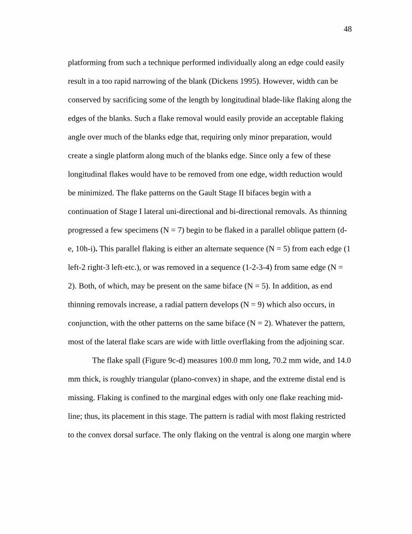
48
platforming from such a technique performed individually along an edge could easily
result in a too rapid narrowing of the blank (Dickens 1995). However, width can be
conserved by sacrificing some of the length by longitudinal blade-like flaking along the
edges of the blanks. Such a flake removal would easily provide an acceptable flaking
angle over much of the blanks edge that, requiring only minor preparation, would
create a single platform along much of the blanks edge. Since only a few of these
longitudinal flakes would have to be removed from one edge, width reduction would
be minimized. The flake patterns on the Gault Stage II bifaces begin with a
continuation of Stage I lateral uni-directional and bi-directional removals. As thinning
progressed a few specimens (N = 7) begin to be flaked in a parallel oblique pattern (d-
e, 10h-i). This parallel flaking is either an alternate sequence (N = 5) from each edge (1
left-2 right-3 left-etc.), or was removed in a sequence (1-2-3-4) from same edge (N =
2). Both, of which, may be present on the same biface (N = 5). In addition, as end
thinning removals increase, a radial pattern develops (N = 9) which also occurs, in
conjunction, with the other patterns on the same biface (N = 2). Whatever the pattern,
most of the lateral flake scars are wide with little overflaking from the adjoining scar.
The flake spall (Figure 9c-d) measures 100.0 mm long, 70.2 mm wide, and 14.0
mm thick, is roughly triangular (plano-convex) in shape, and the extreme distal end is
missing. Flaking is confined to the marginal edges with only one flake reaching mid-
line; thus, its placement in this stage. The pattern is radial with most flaking restricted
to the convex dorsal surface. The only flaking on the ventral is along one margin where
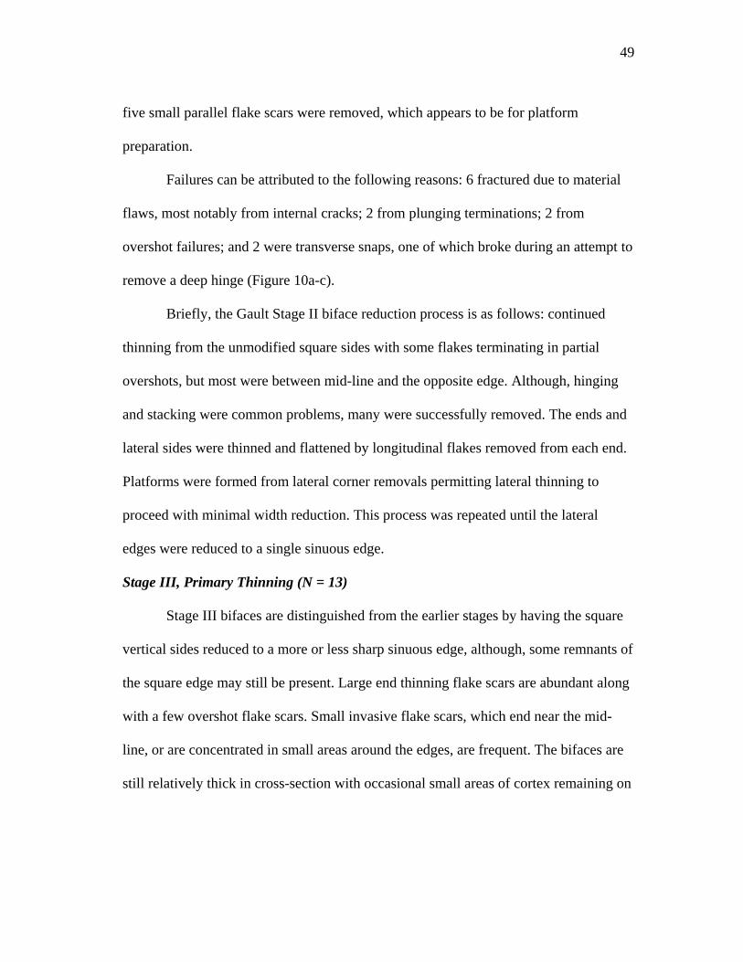
49
five small parallel flake scars were removed, which appears to be for platform
preparation.
Failures can be attributed to the following reasons: 6 fractured due to material
flaws, most notably from internal cracks; 2 from plunging terminations; 2 from
overshot failures; and 2 were transverse snaps, one of which broke during an attempt to
remove a deep hinge (Figure 10a-c).
Briefly, the Gault Stage II biface reduction process is as follows: continued
thinning from the unmodified square sides with some flakes terminating in partial
overshots, but most were between mid-line and the opposite edge. Although, hinging
and stacking were common problems, many were successfully removed. The ends and
lateral sides were thinned and flattened by longitudinal flakes removed from each end.
Platforms were formed from lateral corner removals permitting lateral thinning to
proceed with minimal width reduction. This process was repeated until the lateral
edges were reduced to a single sinuous edge.
Stage III, Primary Thinning (N = 13)
Stage III bifaces are distinguished from the earlier stages by having the square
vertical sides reduced to a more or less sharp sinuous edge, although, some remnants of
the square edge may still be present. Large end thinning flake scars are abundant along
with a few overshot flake scars. Small invasive flake scars, which end near the mid-
line, or are concentrated in small areas around the edges, are frequent. The bifaces are
still relatively thick in cross-section with occasional small areas of cortex remaining on
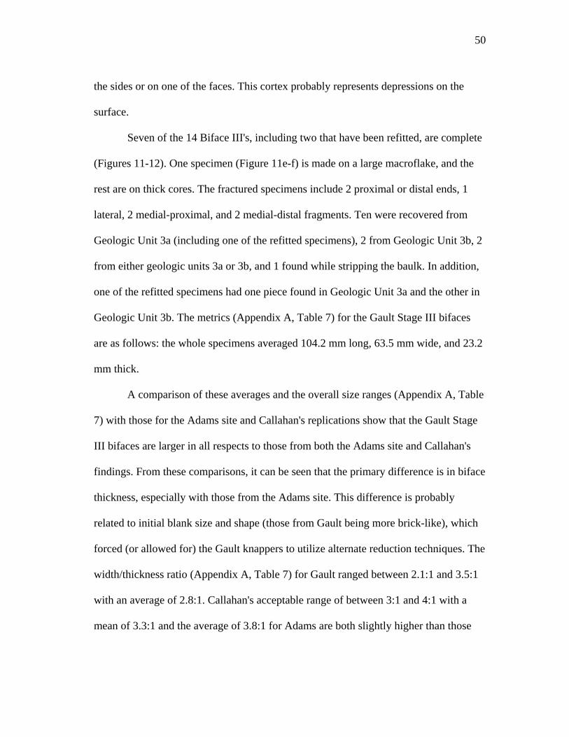
50
the sides or on one of the faces. This cortex probably represents depressions on the
surface.
Seven of the 14 Biface III's, including two that have been refitted, are complete
(Figures 11-12). One specimen (Figure 11e-f) is made on a large macroflake, and the
rest are on thick cores. The fractured specimens include 2 proximal or distal ends, 1
lateral, 2 medial-proximal, and 2 medial-distal fragments. Ten were recovered from
Geologic Unit 3a (including one of the refitted specimens), 2 from Geologic Unit 3b, 2
from either geologic units 3a or 3b, and 1 found while stripping the baulk. In addition,
one of the refitted specimens had one piece found in Geologic Unit 3a and the other in
Geologic Unit 3b. The metrics (Appendix A, Table 7) for the Gault Stage III bifaces
are as follows: the whole specimens averaged 104.2 mm long, 63.5 mm wide, and 23.2
mm thick.
A comparison of these averages and the overall size ranges (Appendix A, Table
7) with those for the Adams site and Callahan's replications show that the Gault Stage
III bifaces are larger in all respects to those from both the Adams site and Callahan's
findings. From these comparisons, it can be seen that the primary difference is in biface
thickness, especially with those from the Adams site. This difference is probably
related to initial blank size and shape (those from Gault being more brick-like), which
forced (or allowed for) the Gault knappers to utilize alternate reduction techniques. The
width/thickness ratio (Appendix A, Table 7) for Gault ranged between 2.1:1 and 3.5:1
with an average of 2.8:1. Callahan's acceptable range of between 3:1 and 4:1 with a
mean of 3.3:1 and the average of 3.8:1 for Adams are both slightly higher than those
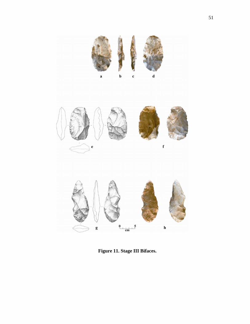
51
Figure 11. Stage III Bifaces.
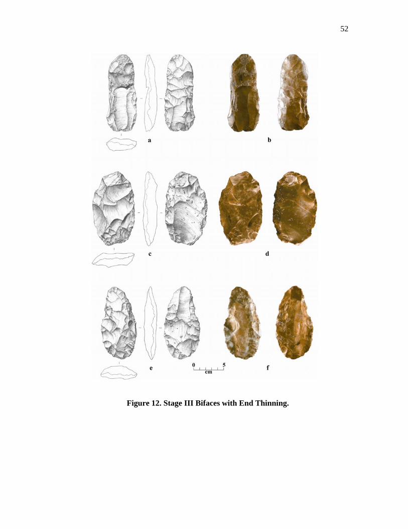
52
Figure 12. Stage III Bifaces with End Thinning.
53
from Gault. In addition, the length/thickness ratios of Callahan's and Adams are both
higher than Gault's. The primary factor for these differences seems to be biface
thickness.
This conclusion is supported when thickness is not factored in. Looking at the
length/width ratio's, it can be seen that Callahan's ratio of 1.8:1 is only slightly less
than the 1.9:1 for Gault, and very close to the 2:1 ratio from Adams. These findings
suggest that, at this stage, the basic biface reduction strategies employed in these
studies are similar with the primary difference being biface thickness.
The flake scar patterns on the Stage III bifaces are similar to the Stage II bifaces
with both lateral and radial forms. The flake scars differ from Stage II scars in they are
frequently longer and narrower, especially those flaked next to each other where some
overlapping occurs. These lateral patterns occur in a variety of bi-directional sequences
that may be combinations on alternate edges of the same face, a single edge, or on only
the ventral or dorsal or both sides. and one with removals that are combinations of
alternately spaced flakes from the Flaking sequences include a parallel sequence (1-2-
3-4), one that alternates between sides (1 left-2 right-3 left-4 right), same edge (1-3-2-
4). For example, one specimen contains a dorsal pattern on one edge that is obliquely
flaked in a 1-3-4-2 alternating sequence with most flakes terminating past mid-line.
The opposite edge is parallel flaked in a 1-2-3-4 sequence with no flakes terminating
past the mid-line. These flakes are small and may have been removed as a platform
preparation for ventral flaking. Whatever pattern or combination of patterns was used,
most tend to be obliquely flaked.
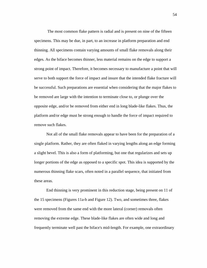
54
The most common flake pattern is radial and is present on nine of the fifteen
specimens. This may be due, in part, to an increase in platform preparation and end
thinning. All specimens contain varying amounts of small flake removals along their
edges. As the biface becomes thinner, less material remains on the edge to support a
strong point of impact. Therefore, it becomes necessary to manufacture a point that will
serve to both support the force of impact and insure that the intended flake fracture will
be successful. Such preparations are essential when considering that the major flakes to
be removed are large with the intention to terminate close to, or plunge over the
opposite edge, and/or be removed from either end in long blade-like flakes. Thus, the
platform and/or edge must be strong enough to handle the force of impact required to
remove such flakes.
Not all of the small flake removals appear to have been for the preparation of a
single platform. Rather, they are often flaked in varying lengths along an edge forming
a slight bevel. This is also a form of platforming, but one that regularizes and sets up
longer portions of the edge as opposed to a specific spot. This idea is supported by the
numerous thinning flake scars, often noted in a parallel sequence, that initiated from
these areas.
End thinning is very prominent in this reduction stage, being present on 11 of
the 15 specimens (Figures 11a-b and Figure 12). Two, and sometimes three, flakes
were removed from the same end with the more lateral (corner) removals often
removing the extreme edge. These blade-like flakes are often wide and long and
frequently terminate well past the biface's mid-length. For example, one extraordinary
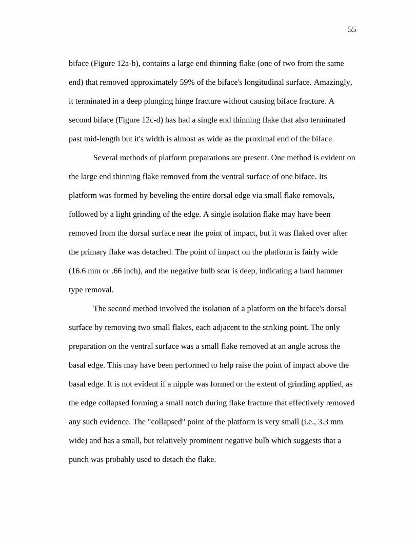
55
biface (Figure 12a-b), contains a large end thinning flake (one of two from the same
end) that removed approximately 59% of the biface's longitudinal surface. Amazingly,
it terminated in a deep plunging hinge fracture without causing biface fracture. A
second biface (Figure 12c-d) has had a single end thinning flake that also terminated
past mid-length but it's width is almost as wide as the proximal end of the biface.
Several methods of platform preparations are present. One method is evident on
the large end thinning flake removed from the ventral surface of one biface. Its
platform was formed by beveling the entire dorsal edge via small flake removals,
followed by a light grinding of the edge. A single isolation flake may have been
removed from the dorsal surface near the point of impact, but it was flaked over after
the primary flake was detached. The point of impact on the platform is fairly wide
(16.6 mm or .66 inch), and the negative bulb scar is deep, indicating a hard hammer
type removal.
The second method involved the isolation of a platform on the biface's dorsal
surface by removing two small flakes, each adjacent to the striking point. The only
preparation on the ventral surface was a small flake removed at an angle across the
basal edge. This may have been performed to help raise the point of impact above the
basal edge. It is not evident if a nipple was formed or the extent of grinding applied, as
the edge collapsed forming a small notch during flake fracture that effectively removed
any such evidence. The "collapsed" point of the platform is very small (i.e., 3.3 mm
wide) and has a small, but relatively prominent negative bulb which suggests that a
punch was probably used to detach the flake.
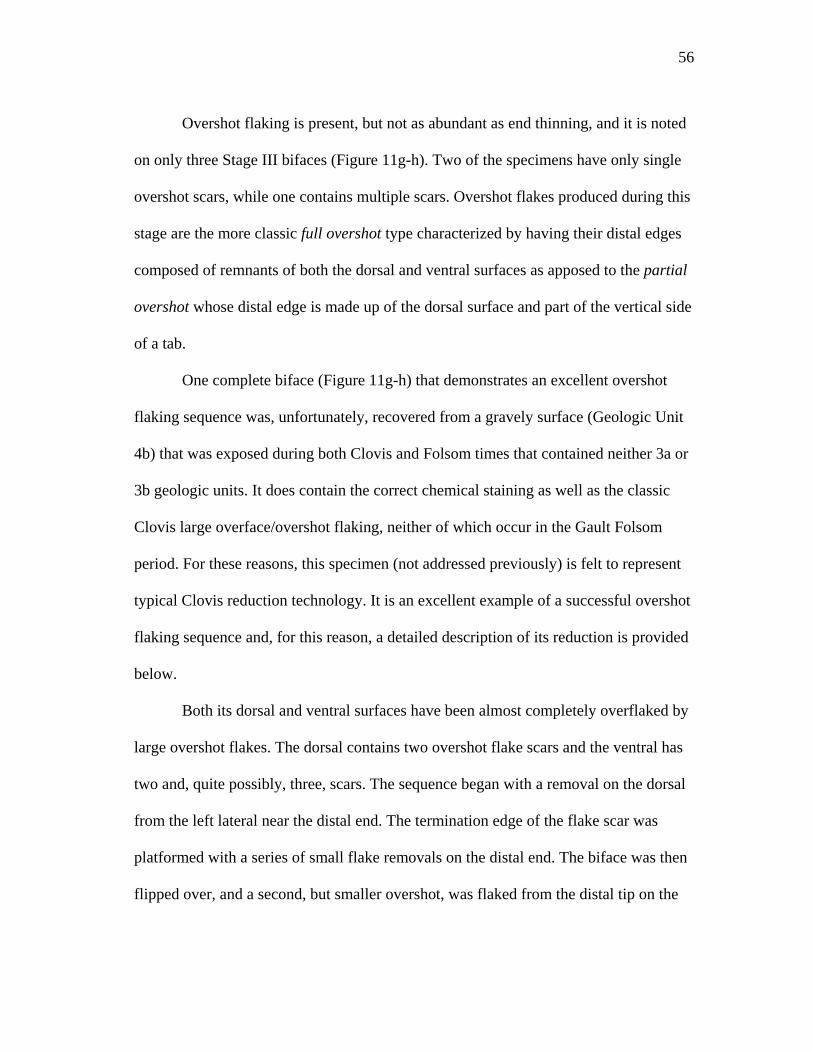
56
Overshot flaking is present, but not as abundant as end thinning, and it is noted
on only three Stage III bifaces (Figure 11g-h). Two of the specimens have only single
overshot scars, while one contains multiple scars. Overshot flakes produced during this
stage are the more classic full overshot type characterized by having their distal edges
composed of remnants of both the dorsal and ventral surfaces as apposed to the partial
overshot whose distal edge is made up of the dorsal surface and part of the vertical side
of a tab.
One complete biface (Figure 11g-h) that demonstrates an excellent overshot
flaking sequence was, unfortunately, recovered from a gravely surface (Geologic Unit
4b) that was exposed during both Clovis and Folsom times that contained neither 3a or
3b geologic units. It does contain the correct chemical staining as well as the classic
Clovis large overface/overshot flaking, neither of which occur in the Gault Folsom
period. For these reasons, this specimen (not addressed previously) is felt to represent
typical Clovis reduction technology. It is an excellent example of a successful overshot
flaking sequence and, for this reason, a detailed description of its reduction is provided
below.
Both its dorsal and ventral surfaces have been almost completely overflaked by
large overshot flakes. The dorsal contains two overshot flake scars and the ventral has
two and, quite possibly, three, scars. The sequence began with a removal on the dorsal
from the left lateral near the distal end. The termination edge of the flake scar was
platformed with a series of small flake removals on the distal end. The biface was then
flipped over, and a second, but smaller overshot, was flaked from the distal tip on the
57
ventral surface. This was followed by another, larger overshot, flaked immediately next
to the small distal on.
At this point, a third possible overshot flake was removed from the ventral's
basal corner at an angle towards the distal end removals, but from the opposite edge.
The termination edge of this flake scar has been removed due to subsequent ventral
edging making it difficult to determine whether it actually plunged over the edge or
not. This removal may have created a slight ridge or hinge between the juncture of the
second and third flake as a smaller flake was removed at this point.
Next, the distal termination edge of the above flake scar was platformed, the
biface flipped over again, and a second, large overshot flaked across the basal half of
the dorsal surface. Some gap exists between this flake and the first dorsal removal on
the distal end, and a platform was formed to flake this portion. Several flakes were
removed, but a severe hinge developed. Further platforming to correct this problem
resulted in a large portion of the edge to collapse (due to a crack), forming a large
concavity and causing the biface to be abandoned.
Even though some additional flake removals would be necessary to completely
smooth and continue to thin the remaining surface, the strategy of large overshot or
overface flaking was enough to sufficiently flatten and/or smooth most of the dorsal
and ventral surfaces by the removal of only four or five large flakes. It is apparent that,
through the skill and control of the knapper, the plunging nature of overshot flaking
was minimized. The result was that little of the opposite (termination) edges were
removed, the flakes either terminating on the immediate edge, or removed only a slight
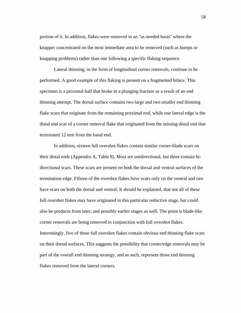
58
portion of it. In addition, flakes were removed in an "as needed basis" where the
knapper concentrated on the most immediate area to be removed (such as humps or
knapping problems) rather than one following a specific flaking sequence.
Lateral thinning, in the form of longitudinal corner removals, continue to be
performed. A good example of this flaking is present on a fragmented biface. This
specimen is a proximal half that broke in a plunging fracture as a result of an end
thinning attempt. The dorsal surface contains two large and two smaller end thinning
flake scars that originate from the remaining proximal end, while one lateral edge is the
distal end scar of a corner removal flake that originated from the missing distal end that
terminated 12 mm from the basal end.
In addition, sixteen full overshot flakes contain similar corner-blade scars on
their distal ends (Appendix A, Table 8). Most are unidirectional, but three contain bi-
directional scars. These scars are present on both the dorsal and ventral surfaces of the
termination edge. Fifteen of the overshot flakes have scars only on the ventral and two
have scars on both the dorsal and ventral. It should be explained, that not all of these
full overshot flakes may have originated in this particular reductive stage, but could
also be products from later, and possibly earlier stages as well. The point is blade-like
corner removals are being removed in conjunction with full overshot flakes.
Interestingly, five of these full overshot flakes contain obvious end thinning flake scars
on their dorsal surfaces. This suggests the possibility that corner/edge removals may be
part of the overall end thinning strategy, and as such, represent those end thinning
flakes removed from the lateral corners.
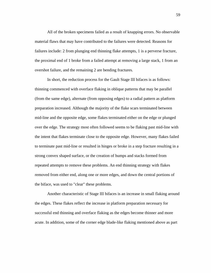
59
All of the broken specimens failed as a result of knapping errors. No observable
material flaws that may have contributed to the failures were detected. Reasons for
failures include: 2 from plunging end thinning flake attempts, 1 is a perverse fracture,
the proximal end of 1 broke from a failed attempt at removing a large stack, 1 from an
overshot failure, and the remaining 2 are bending fractures.
In short, the reduction process for the Gault Stage III bifaces is as follows:
thinning commenced with overface flaking in oblique patterns that may be parallel
(from the same edge), alternate (from opposing edges) to a radial pattern as platform
preparation increased. Although the majority of the flake scars terminated between
mid-line and the opposite edge, some flakes terminated either on the edge or plunged
over the edge. The strategy most often followed seems to be flaking past mid-line with
the intent that flakes terminate close to the opposite edge. However, many flakes failed
to terminate past mid-line or resulted in hinges or broke in a step fracture resulting in a
strong convex shaped surface, or the creation of humps and stacks formed from
repeated attempts to remove these problems. An end thinning strategy with flakes
removed from either end, along one or more edges, and down the central portions of
the biface, was used to "clear" these problems.
Another characteristic of Stage III bifaces is an increase in small flaking around
the edges. These flakes reflect the increase in platform preparation necessary for
successful end thinning and overface flaking as the edges become thinner and more
acute. In addition, some of the corner edge blade-like flaking mentioned above as part
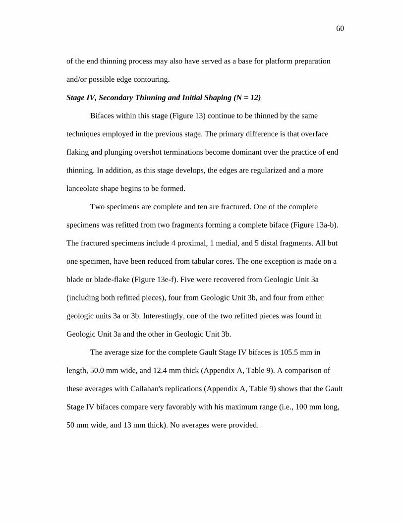
60
of the end thinning process may also have served as a base for platform preparation
and/or possible edge contouring.
Stage IV, Secondary Thinning and Initial Shaping (N = 12)
Bifaces within this stage (Figure 13) continue to be thinned by the same
techniques employed in the previous stage. The primary difference is that overface
flaking and plunging overshot terminations become dominant over the practice of end
thinning. In addition, as this stage develops, the edges are regularized and a more
lanceolate shape begins to be formed.
Two specimens are complete and ten are fractured. One of the complete
specimens was refitted from two fragments forming a complete biface (Figure 13a-b).
The fractured specimens include 4 proximal, 1 medial, and 5 distal fragments. All but
one specimen, have been reduced from tabular cores. The one exception is made on a
blade or blade-flake (Figure 13e-f). Five were recovered from Geologic Unit 3a
(including both refitted pieces), four from Geologic Unit 3b, and four from either
geologic units 3a or 3b. Interestingly, one of the two refitted pieces was found in
Geologic Unit 3a and the other in Geologic Unit 3b.
The average size for the complete Gault Stage IV bifaces is 105.5 mm in
length, 50.0 mm wide, and 12.4 mm thick (Appendix A, Table 9). A comparison of
these averages with Callahan's replications (Appendix A, Table 9) shows that the Gault
Stage IV bifaces compare very favorably with his maximum range (i.e., 100 mm long,
50 mm wide, and 13 mm thick). No averages were provided.
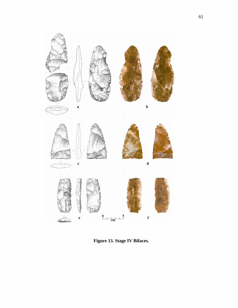
61
Figure 13. Stage IV Bifaces.
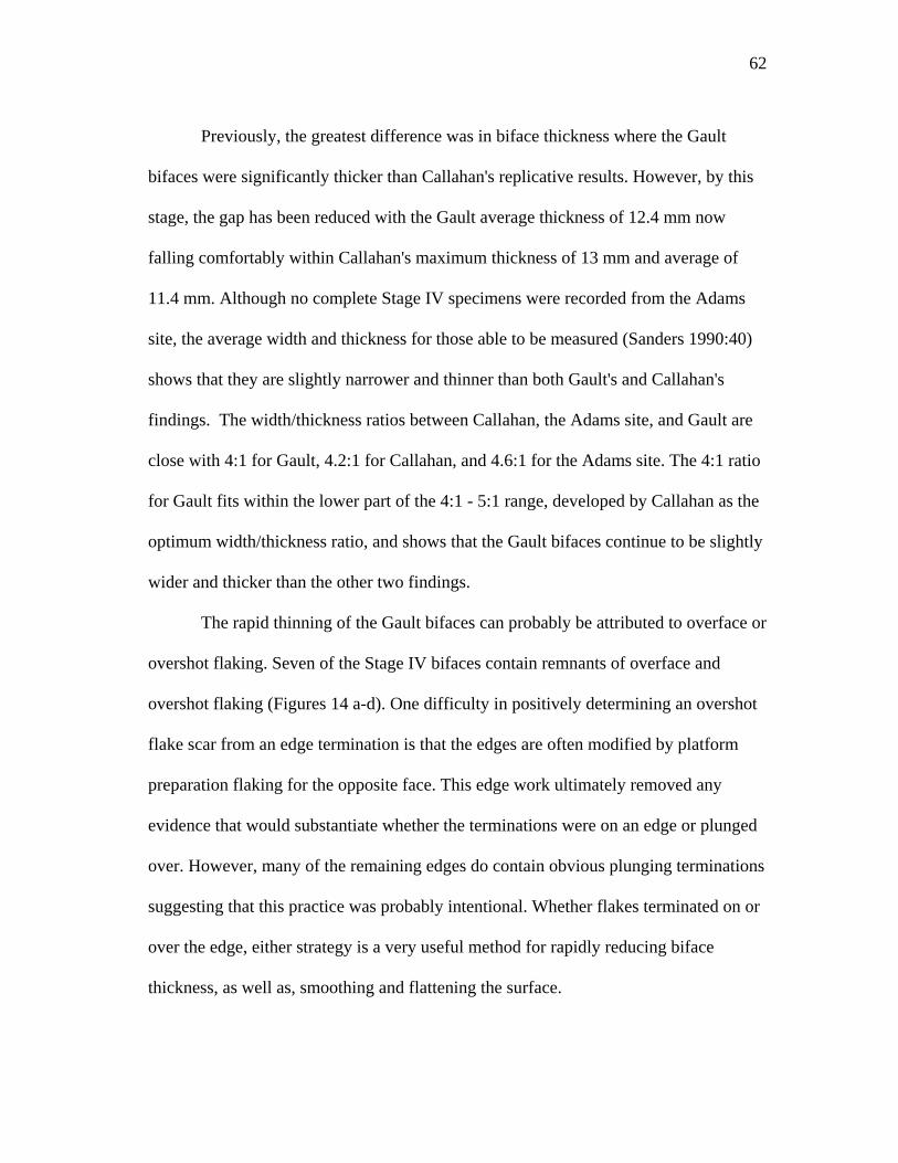
62
Previously, the greatest difference was in biface thickness where the Gault
bifaces were significantly thicker than Callahan's replicative results. However, by this
stage, the gap has been reduced with the Gault average thickness of 12.4 mm now
falling comfortably within Callahan's maximum thickness of 13 mm and average of
11.4 mm. Although no complete Stage IV specimens were recorded from the Adams
site, the average width and thickness for those able to be measured (Sanders 1990:40)
shows that they are slightly narrower and thinner than both Gault's and Callahan's
findings. The width/thickness ratios between Callahan, the Adams site, and Gault are
close with 4:1 for Gault, 4.2:1 for Callahan, and 4.6:1 for the Adams site. The 4:1 ratio
for Gault fits within the lower part of the 4:1 - 5:1 range, developed by Callahan as the
optimum width/thickness ratio, and shows that the Gault bifaces continue to be slightly
wider and thicker than the other two findings.
The rapid thinning of the Gault bifaces can probably be attributed to overface or
overshot flaking. Seven of the Stage IV bifaces contain remnants of overface and
overshot flaking (Figures 14 a-d). One difficulty in positively determining an overshot
flake scar from an edge termination is that the edges are often modified by platform
preparation flaking for the opposite face. This edge work ultimately removed any
evidence that would substantiate whether the terminations were on an edge or plunged
over. However, many of the remaining edges do contain obvious plunging terminations
suggesting that this practice was probably intentional. Whether flakes terminated on or
over the edge, either strategy is a very useful method for rapidly reducing biface
thickness, as well as, smoothing and flattening the surface.
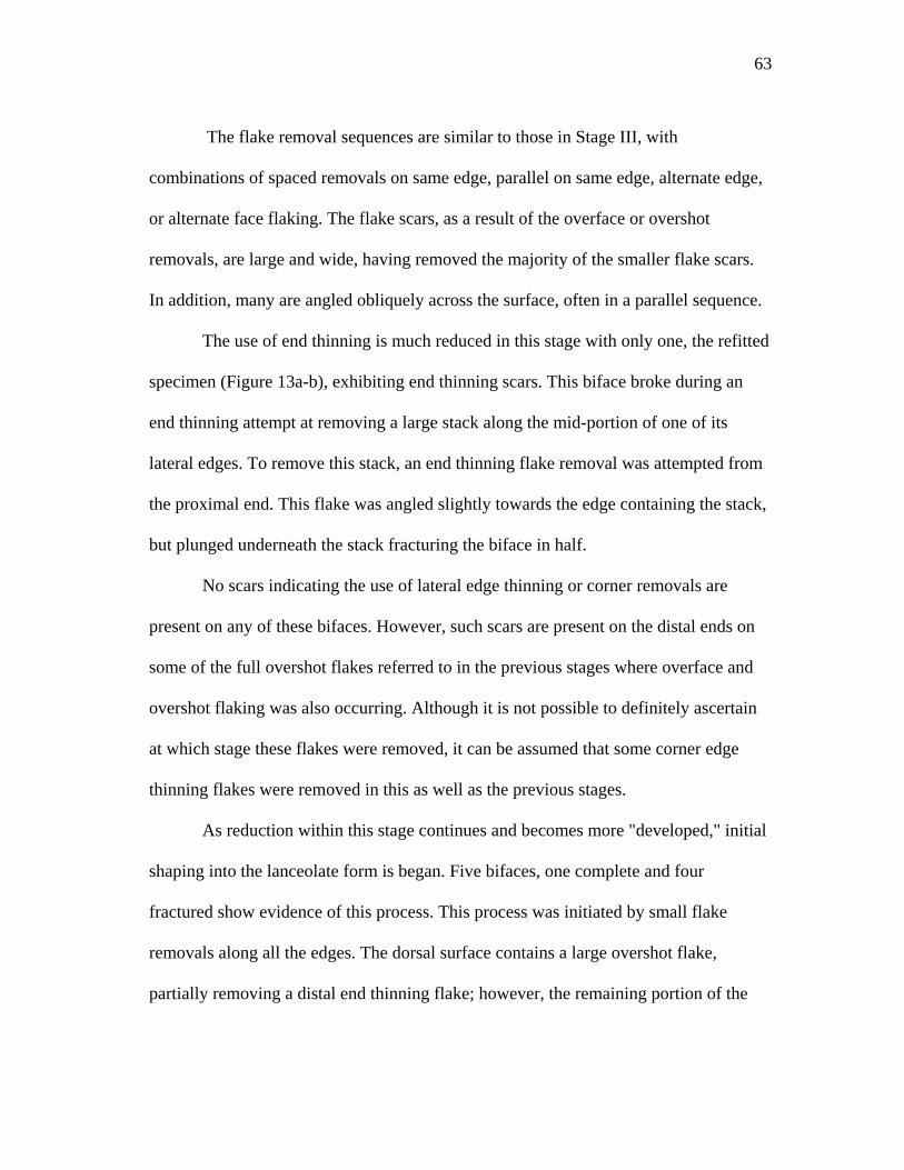
63
The flake removal sequences are similar to those in Stage III, with
combinations of spaced removals on same edge, parallel on same edge, alternate edge,
or alternate face flaking. The flake scars, as a result of the overface or overshot
removals, are large and wide, having removed the majority of the smaller flake scars.
In addition, many are angled obliquely across the surface, often in a parallel sequence.
The use of end thinning is much reduced in this stage with only one, the refitted
specimen (Figure 13a-b), exhibiting end thinning scars. This biface broke during an
end thinning attempt at removing a large stack along the mid-portion of one of its
lateral edges. To remove this stack, an end thinning flake removal was attempted from
the proximal end. This flake was angled slightly towards the edge containing the stack,
but plunged underneath the stack fracturing the biface in half.
No scars indicating the use of lateral edge thinning or corner removals are
present on any of these bifaces. However, such scars are present on the distal ends on
some of the full overshot flakes referred to in the previous stages where overface and
overshot flaking was also occurring. Although it is not possible to definitely ascertain
at which stage these flakes were removed, it can be assumed that some corner edge
thinning flakes were removed in this as well as the previous stages.
As reduction within this stage continues and becomes more "developed," initial
shaping into the lanceolate form is began. Five bifaces, one complete and four
fractured show evidence of this process. This process was initiated by small flake
removals along all the edges. The dorsal surface contains a large overshot flake,
partially removing a distal end thinning flake; however, the remaining portion of the
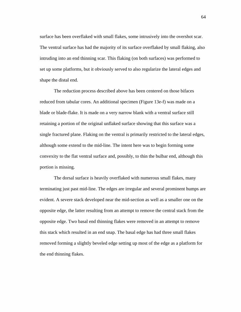
64
surface has been overflaked with small flakes, some intrusively into the overshot scar.
The ventral surface has had the majority of its surface overflaked by small flaking, also
intruding into an end thinning scar. This flaking (on both surfaces) was performed to
set up some platforms, but it obviously served to also regularize the lateral edges and
shape the distal end.
The reduction process described above has been centered on those bifaces
reduced from tabular cores. An additional specimen (Figure 13e-f) was made on a
blade or blade-flake. It is made on a very narrow blank with a ventral surface still
retaining a portion of the original unflaked surface showing that this surface was a
single fractured plane. Flaking on the ventral is primarily restricted to the lateral edges,
although some extend to the mid-line. The intent here was to begin forming some
convexity to the flat ventral surface and, possibly, to thin the bulbar end, although this
portion is missing.
The dorsal surface is heavily overflaked with numerous small flakes, many
terminating just past mid-line. The edges are irregular and several prominent humps are
evident. A severe stack developed near the mid-section as well as a smaller one on the
opposite edge, the latter resulting from an attempt to remove the central stack from the
opposite edge. Two basal end thinning flakes were removed in an attempt to remove
this stack which resulted in an end snap. The basal edge has had three small flakes
removed forming a slightly beveled edge setting up most of the edge as a platform for
the end thinning flakes.
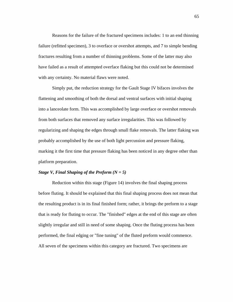
65
Reasons for the failure of the fractured specimens includes: 1 to an end thinning
failure (refitted specimen), 3 to overface or overshot attempts, and 7 to simple bending
fractures resulting from a number of thinning problems. Some of the latter may also
have failed as a result of attempted overface flaking but this could not be determined
with any certainty. No material flaws were noted.
Simply put, the reduction strategy for the Gault Stage IV bifaces involves the
flattening and smoothing of both the dorsal and ventral surfaces with initial shaping
into a lanceolate form. This was accomplished by large overface or overshot removals
from both surfaces that removed any surface irregularities. This was followed by
regularizing and shaping the edges through small flake removals. The latter flaking was
probably accomplished by the use of both light percussion and pressure flaking,
marking it the first time that pressure flaking has been noticed in any degree other than
platform preparation.
Stage V, Final Shaping of the Preform (N = 5)
Reduction within this stage (Figure 14) involves the final shaping process
before fluting. It should be explained that this final shaping process does not mean that
the resulting product is in its final finished form; rather, it brings the preform to a stage
that is ready for fluting to occur. The "finished" edges at the end of this stage are often
slightly irregular and still in need of some shaping. Once the fluting process has been
performed, the final edging or "fine tuning" of the fluted preform would commence.
All seven of the specimens within this category are fractured. Two specimens are
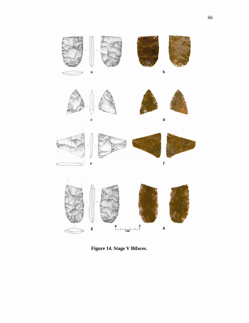
66
Figure 14. Stage V Bifaces.
67
proximal fragments, 1 is a medial fragment formed by the refitting of two small "ultra
thin" fragments, and 2 are distal fragments (Figure 14e-f). Failure of these preforms
include four transverse bending or end snap fractures and one that shattered. Not one
appears to have failed due to material flaws or knapping errors such as stacking or
hinging problems. The shattered specimen (the refitted "ultra thin" fragments) appears
to have either been smashed or dropped onto a hard surface rather than breaking as a
result of a knapping failure. Five were recovered from Geologic Unit 3a (including
both refitted pieces), and one from geologic units 3a or 3b.
Since all the Stage V bifaces are fragmented, the measurements taken were
performed only on those specimens that were believed to represent maximum width.
For example, any fragments having one or more edges that were still expanding were
excluded. The result (Appendix A, Table 10) was an average width of 39.20 mm and
thickness of 8.75 mm giving a width/thickness ratio of 4.75:1. Table 10 shows how
these figures compare to the Adams site and Callahan's findings. Unfortunately,
Callahan does not provide any size ranges for his Stage V replications, but does
establish a width/thickness ratio of between 4:1 and 6:1+. The Gault findings fall
comfortably within his range, albeit, the Gault bifaces are still slightly thicker.
Sanders (1990:43) divided the Stage V bifaces from the Adams site into two
categories: two finished non-fluted specimens possibly used as knives, and four distal
fragments that were believed to have fractured during the Stage V reduction process
prior to fluting. Measurements from these show that they are narrower and thicker than
those from Gault. Sanders (1990:43-44) explains that the fragmented bifaces are not
68
clear examples for Stage V preforms and were placed in this category as a matter of
convenience and that they need additional reduction in thickness and width before the
fluting process could proceed. This suggests that they may actually be late Stage IV or
very early Stage V bifaces, as opposed to a more developed and recognizable Stage V.
Regardless of the category, the difference in width between Gault and Adams (7.5 -
14.5 mm) is significant and may be related back to initial blank size, with those from
Gault being made on thicker and wider blanks.
The Gault preforms were shaped by the removal of small flakes from the basal
and lateral edges by light percussion and pressure flaking. This flaking removed any
high spots or remaining surface irregularities while shaping the preform into a basic
lanceolate form. Some portions of the surface are completely flaked over while
remnants of large scars, such as overface or overshot flakes, may only have their
immediate edges flaked. Two examples, a proximal fragment and a distal fragment
(Figure 14a-b, g-h and Figure 14c-d), typify this strategy. These specimens contain
remnants of large scars in the centers of both of their dorsal and ventral surfaces that
have been isolated as a result of small flake removals from around their edges. This
"edging" has completely eliminated the termination type of the larger flakes, leaving
only a suggestion as to whether they terminated on the edge or plunged into an
overshot type termination.
Two fragments representing the midsection of a very thin biface were refitted
together (Figure 14e-f); however, it cannot be determined what part of the biface these
69
fragments originated from other than they come from the approximate midsection. The
point of this description is that it's width of 59.9 mm and thickness of 5.0 mm result in
a width/thickness ratio of 11.98 (12:1), which is considerably higher than the average
of 5:1 computed for the other specimens. This suggests that it may be a fragment of a
very large and thin biface similar to the "ultra thin bifaces" that are often found
associated with Folsom technology with width/thickness ratios that range between 7:1
and 13:1 (Collins 1999b:21-22). Although the flaking patterns on both surfaces of this
specimen reflect Stage V characteristics, the extreme thinness indicates that it is
probably a shattered fragment of an un-fluted tool and not part of the Stage V reduction
process. Therefore, it is classified here as an "anomaly."
The final development within the Stage V reduction process is to form the
preform into an approximate lanceolate shape. Through continued light percussion and
pressure flaking, the preforms are shaped into narrow bifaces having rounded convex
basal edges and "bullet "- shaped tips. Some portions of the basal and lateral edges
have been ground for platform preparation. In longitudinal cross-section, they are flat
and only taper towards the distal tip with the proximal half and mid-section retaining
the (approximate) same thickness. The lack of tapering on the proximal end was
retained to facilitate flute removal where some thickness is required.
Stage VI, Fluting and Finishing the Point (N = 3)
This is the final stage (Figure 15) in the Clovis point manufacturing process that
is intended to prepare the base for the purpose of hafting. It should be mentioned that
not all bifaces were reduced to produce a fluted product. The reduction process could
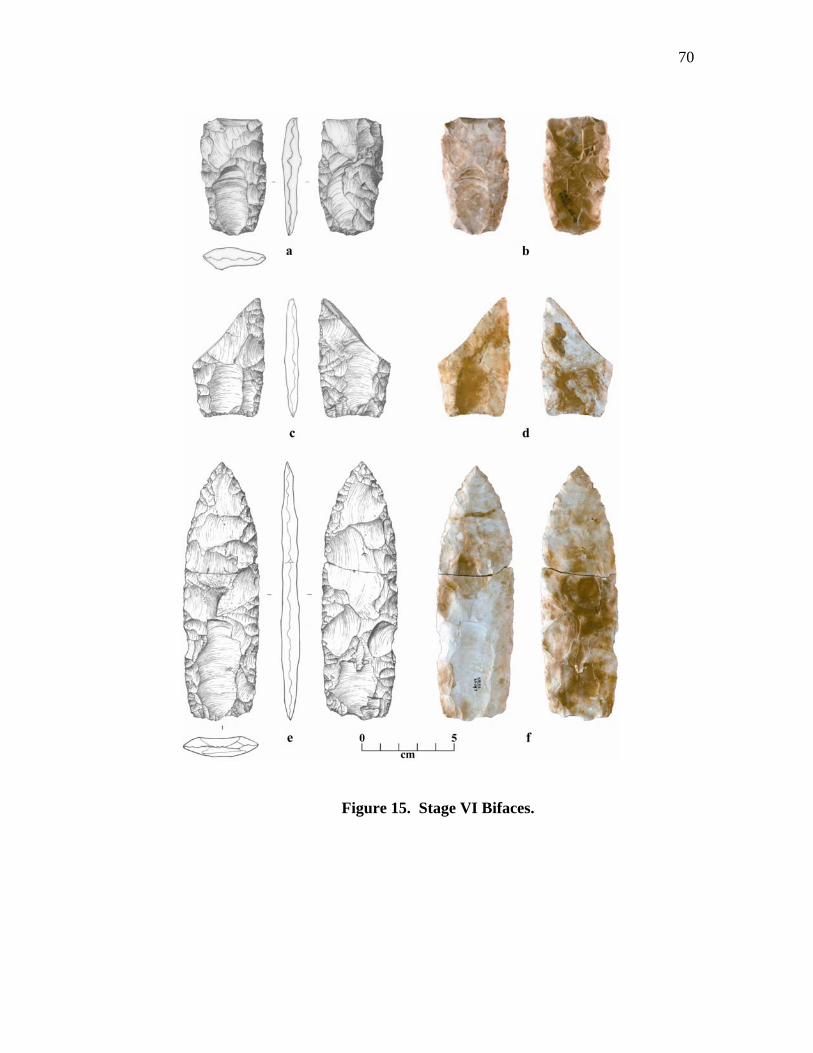
70
Figure 15. Stage VI Bifaces.
71
easily have been stopped at any point to satisfy a need for any number of specific tool
forms such as choppers, adzes, and scrapers. However, for those selected for fluting,
the preform has been sufficiently thinned and shaped to a form satisfactory for the
fluting process to proceed.
Three specimens are assigned to the Stage VI category. They include two
proximal fragments and a complete specimen formed by the refitting of two halves
(Figure 15). All were found in Geologic Unit 3a. These specimens are unique enough
that each will be described individually below.
Specimen 1
This specimen (Figure 15a-b) is the proximal half that fragmented due to a
transverse fracture. Interestingly, it has not been chemically stained, typical of the
majority of chert recovered, but is patinated a gray/white. It measures 63.3 mm long,
36.4 mm wide and is 10.2 mm thick. There is a flute on both it's dorsal and ventral
surfaces and a large overface flake that terminated on the opposing lateral edge of the
ventral surface. Small flake removals are present along the margins of both surfaces
and several large flakes terminating near the mid-line are present on the dorsal surface.
One of these flakes terminated in a step fracture and may have been the cause for the
resulting failure. The lateral edges are slightly irregular and one side is slightly thicker
than the other.
The first flute was a shallow flake removed from the dorsal surface. The type of
basal preparation used has been removed by the subsequent beveling of the basal edge
for the ventral flute removal. In addition to the edge modification, one of the lateral
72
edges, beginning on the basal corner, has been obliquely flaked and intruded over the
flute scar to the midline. This left only half of the flute channel, which appears, to
angle towards the other edge. In all probability, there would have to be another flute
removed before it would be considered "finished," and the lateral intrusion flakes may
have been flaked to "contour" the surface for that purpose.
The ventral flute was successfully flaked but the preform probably end snapped
as a result of it's removal. The striking platform was prepared by beveling the edge on
the opposite (dorsal) surface. A slight protrusion (nipple) was formed with two
isolation flakes removed; one on each side of the nipple. Then the entire edge was
ground. The flute flake was probably removed with a punch leaving a small concavity
at the point of impact. The fractured edge at this point measures 4.9 mm wide with the
flake scar rapidly expanding to 17.7 mm in width and a maximum length of 38.4 mm.
Specimen 2
This specimen (Figure 15c-d) is the proximal portion that fractured just in front
of the longest flute scar. The fracture is a perverse type that broke at a steep angle. It
measures 64.3 mm long, 39.3 mm wide, and 6.7 mm thick. There are two flute scars on
the dorsal surface and a single one on the ventral surface. There is a large flake scar on
the dorsal surface in front of the double flute scars that have been isolated by marginal
flaking. Most of the surface in front of the ventral flute scar was removed with the
missing distal portion, but a remnant of one large scar from the left lateral edge
remains. Marginal flaking is present on most of the remaining edges of both surfaces.
73
The first flute was removed from the ventral surface. It measures 42.1 mm in
length and 23.3 mm wide. Remnants of some platform preparation, in the form of edge
beveling, remains on the dorsal edge. Grinding is present on the extreme basal edge
where it initially extended across the entire edge. At present, it occurs only near the
corners. The rest of the edge was removed with the striking platform and flute flakes.
Some ventral lateral intrusion is evident on both edges suggesting that basal shaping
occurred prior to the dorsal flute removals.
There are two dorsal flute scars present. The presence of multiple flute scars is
not surprising as they have been observed on other Clovis points (Meltzer 1987:55;
Howard 1990:258-259). The first flute may have angled too far to one side,
necessitating the removal of a second flute which probably caused the preform to
break. The basal edge on the ventral surface has been beveled and intrudes over the
entire basal width of the ventral scar. Other than this beveling, no other platform
preparation is indicated such as a nipple or isolation flaking. The remnant of the first
flute scar measures 24.4 mm in length by 8.7 mm in width, and the second is 28.1 mm
long and 20.6 mm wide. Both the ventral and dorsal flute scars are shallow and wide
with no evident negative bulb, indicating a probable soft hammer type removal.
Specimen 3
This specimen (Figure 15e-f) has been refitted together from two fragments
forming a complete preform. It is an excellent example of how Clovis preforms were
prepared for the final fluting process. As a result of it's breakage during the last fluting
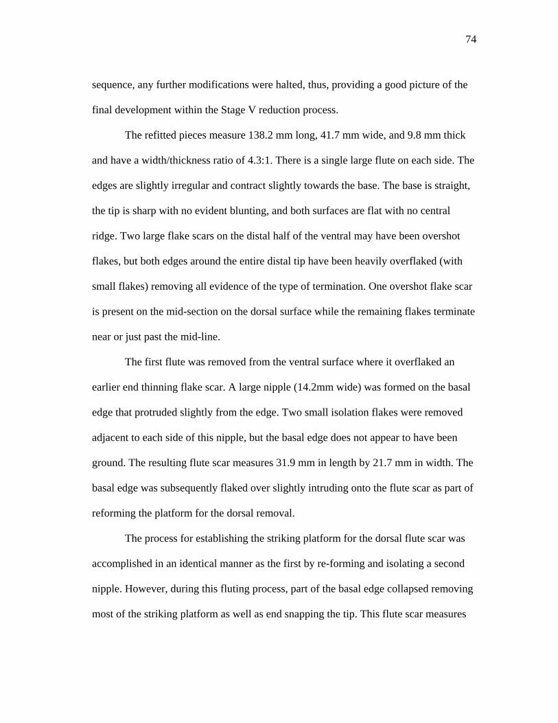
74
sequence, any further modifications were halted, thus, providing a good picture of the
final development within the Stage V reduction process.
The refitted pieces measure 138.2 mm long, 41.7 mm wide, and 9.8 mm thick
and have a width/thickness ratio of 4.3:1. There is a single large flute on each side. The
edges are slightly irregular and contract slightly towards the base. The base is straight,
the tip is sharp with no evident blunting, and both surfaces are flat with no central
ridge. Two large flake scars on the distal half of the ventral may have been overshot
flakes, but both edges around the entire distal tip have been heavily overflaked (with
small flakes) removing all evidence of the type of termination. One overshot flake scar
is present on the mid-section on the dorsal surface while the remaining flakes terminate
near or just past the mid-line.
The first flute was removed from the ventral surface where it overflaked an
earlier end thinning flake scar. A large nipple (14.2mm wide) was formed on the basal
edge that protruded slightly from the edge. Two small isolation flakes were removed
adjacent to each side of this nipple, but the basal edge does not appear to have been
ground. The resulting flute scar measures 31.9 mm in length by 21.7 mm in width. The
basal edge was subsequently flaked over slightly intruding onto the flute scar as part of
reforming the platform for the dorsal removal.
The process for establishing the striking platform for the dorsal flute scar was
accomplished in an identical manner as the first by re-forming and isolating a second
nipple. However, during this fluting process, part of the basal edge collapsed removing
most of the striking platform as well as end snapping the tip. This flute scar measures
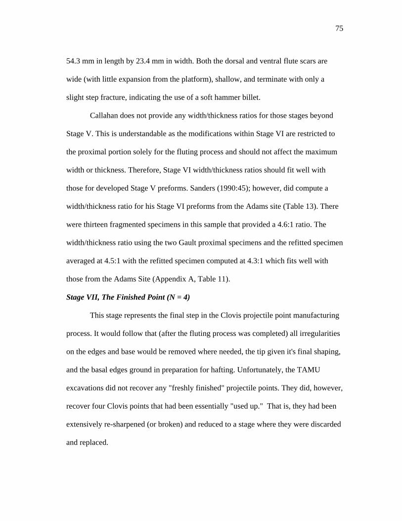
75
54.3 mm in length by 23.4 mm in width. Both the dorsal and ventral flute scars are
wide (with little expansion from the platform), shallow, and terminate with only a
slight step fracture, indicating the use of a soft hammer billet.
Callahan does not provide any width/thickness ratios for those stages beyond
Stage V. This is understandable as the modifications within Stage VI are restricted to
the proximal portion solely for the fluting process and should not affect the maximum
width or thickness. Therefore, Stage VI width/thickness ratios should fit well with
those for developed Stage V preforms. Sanders (1990:45); however, did compute a
width/thickness ratio for his Stage VI preforms from the Adams site (Table 13). There
were thirteen fragmented specimens in this sample that provided a 4.6:1 ratio. The
width/thickness ratio using the two Gault proximal specimens and the refitted specimen
averaged at 4.5:1 with the refitted specimen computed at 4.3:1 which fits well with
those from the Adams Site (Appendix A, Table 11).
Stage VII, The Finished Point (N = 4)
This stage represents the final step in the Clovis projectile point manufacturing
process. It would follow that (after the fluting process was completed) all irregularities
on the edges and base would be removed where needed, the tip given it's final shaping,
and the basal edges ground in preparation for hafting. Unfortunately, the TAMU
excavations did not recover any "freshly finished" projectile points. They did, however,
recover four Clovis points that had been essentially "used up." That is, they had been
extensively re-sharpened (or broken) and reduced to a stage where they were discarded
and replaced.
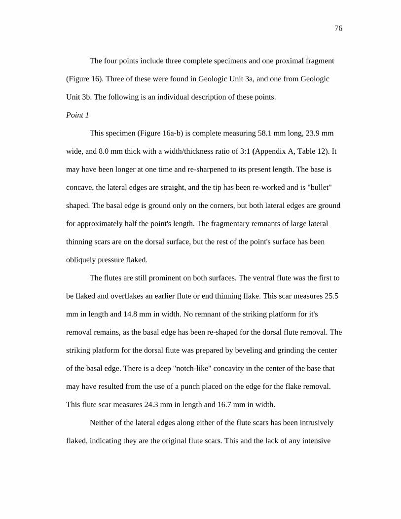
76
The four points include three complete specimens and one proximal fragment
(Figure 16). Three of these were found in Geologic Unit 3a, and one from Geologic
Unit 3b. The following is an individual description of these points.
Point 1
This specimen (Figure 16a-b) is complete measuring 58.1 mm long, 23.9 mm
wide, and 8.0 mm thick with a width/thickness ratio of 3:1 (Appendix A, Table 12). It
may have been longer at one time and re-sharpened to its present length. The base is
concave, the lateral edges are straight, and the tip has been re-worked and is "bullet"
shaped. The basal edge is ground only on the corners, but both lateral edges are ground
for approximately half the point's length. The fragmentary remnants of large lateral
thinning scars are on the dorsal surface, but the rest of the point's surface has been
obliquely pressure flaked.
The flutes are still prominent on both surfaces. The ventral flute was the first to
be flaked and overflakes an earlier flute or end thinning flake. This scar measures 25.5
mm in length and 14.8 mm in width. No remnant of the striking platform for it's
removal remains, as the basal edge has been re-shaped for the dorsal flute removal. The
striking platform for the dorsal flute was prepared by beveling and grinding the center
of the basal edge. There is a deep "notch-like" concavity in the center of the base that
may have resulted from the use of a punch placed on the edge for the flake removal.
This flute scar measures 24.3 mm in length and 16.7 mm in width.
Neither of the lateral edges along either of the flute scars has been intrusively
flaked, indicating they are the original flute scars. This and the lack of any intensive
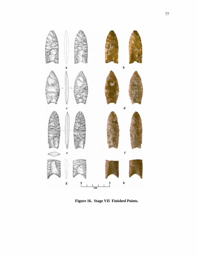
77
Figure 16. Stage VII Finished Points.
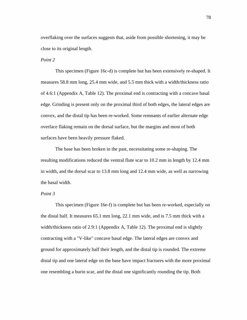
78
overflaking over the surfaces suggests that, aside from possible shortening, it may be
close to its original length.
Point 2
This specimen (Figure 16c-d) is complete but has been extensively re-shaped. It
measures 58.8 mm long, 25.4 mm wide, and 5.5 mm thick with a width/thickness ratio
of 4.6:1 (Appendix A, Table 12). The proximal end is contracting with a concave basal
edge. Grinding is present only on the proximal third of both edges, the lateral edges are
convex, and the distal tip has been re-worked. Some remnants of earlier alternate edge
overface flaking remain on the dorsal surface, but the margins and most of both
surfaces have been heavily pressure flaked.
The base has been broken in the past, necessitating some re-shaping. The
resulting modifications reduced the ventral flute scar to 10.2 mm in length by 12.4 mm
in width, and the dorsal scar to 13.8 mm long and 12.4 mm wide, as well as narrowing
the basal width.
Point 3
This specimen (Figure 16e-f) is complete but has been re-worked, especially on
the distal half. It measures 65.1 mm long, 22.1 mm wide, and is 7.5 mm thick with a
width/thickness ratio of 2.9:1 (Appendix A, Table 12). The proximal end is slightly
contracting with a "V-like" concave basal edge. The lateral edges are convex and
ground for approximately half their length, and the distal tip is rounded. The extreme
distal tip and one lateral edge on the base have impact fractures with the more proximal
one resembling a burin scar, and the distal one significantly rounding the tip. Both
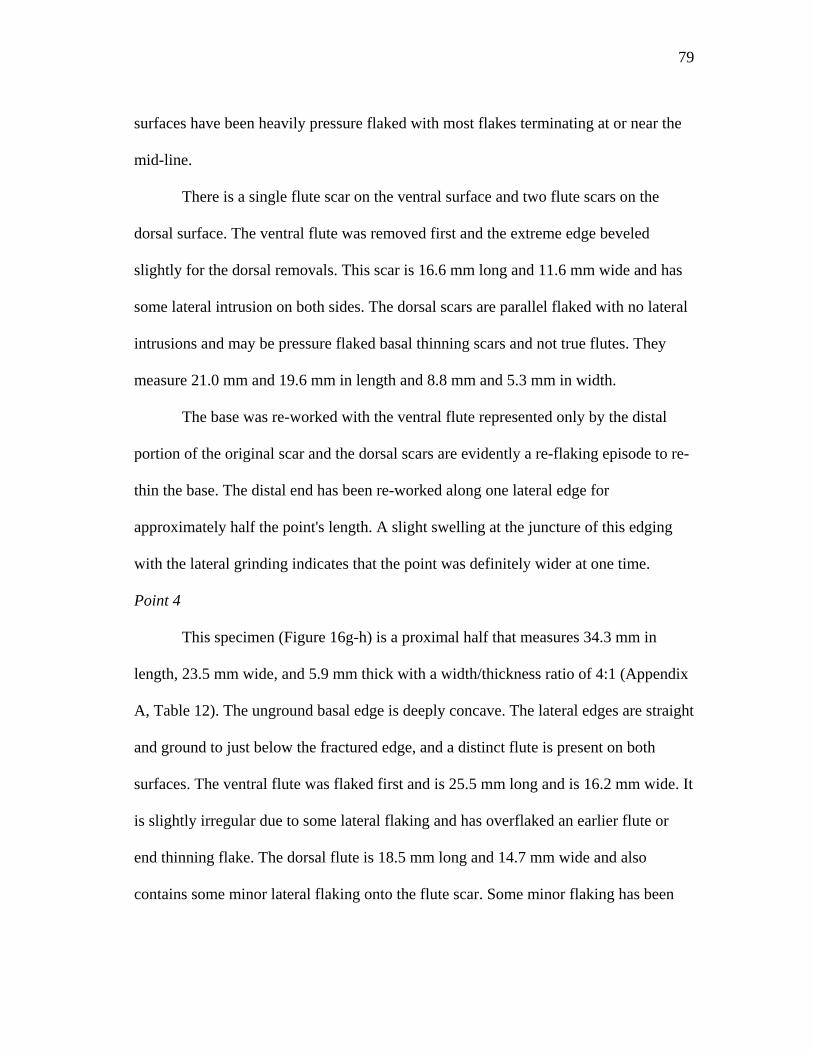
79
surfaces have been heavily pressure flaked with most flakes terminating at or near the
mid-line.
There is a single flute scar on the ventral surface and two flute scars on the
dorsal surface. The ventral flute was removed first and the extreme edge beveled
slightly for the dorsal removals. This scar is 16.6 mm long and 11.6 mm wide and has
some lateral intrusion on both sides. The dorsal scars are parallel flaked with no lateral
intrusions and may be pressure flaked basal thinning scars and not true flutes. They
measure 21.0 mm and 19.6 mm in length and 8.8 mm and 5.3 mm in width.
The base was re-worked with the ventral flute represented only by the distal
portion of the original scar and the dorsal scars are evidently a re-flaking episode to re-
thin the base. The distal end has been re-worked along one lateral edge for
approximately half the point's length. A slight swelling at the juncture of this edging
with the lateral grinding indicates that the point was definitely wider at one time.
Point 4
This specimen (Figure 16g-h) is a proximal half that measures 34.3 mm in
length, 23.5 mm wide, and 5.9 mm thick with a width/thickness ratio of 4:1 (Appendix
A, Table 12). The unground basal edge is deeply concave. The lateral edges are straight
and ground to just below the fractured edge, and a distinct flute is present on both
surfaces. The ventral flute was flaked first and is 25.5 mm long and is 16.2 mm wide. It
is slightly irregular due to some lateral flaking and has overflaked an earlier flute or
end thinning flake. The dorsal flute is 18.5 mm long and 14.7 mm wide and also
contains some minor lateral flaking onto the flute scar. Some minor flaking has been
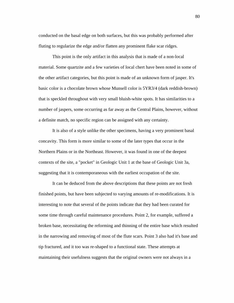
80
conducted on the basal edge on both surfaces, but this was probably performed after
fluting to regularize the edge and/or flatten any prominent flake scar ridges.
This point is the only artifact in this analysis that is made of a non-local
material. Some quartzite and a few varieties of local chert have been noted in some of
the other artifact categories, but this point is made of an unknown form of jasper. It's
basic color is a chocolate brown whose Munsell color is 5YR3/4 (dark reddish-brown)
that is speckled throughout with very small bluish-white spots. It has similarities to a
number of jaspers, some occurring as far away as the Central Plains, however, without
a definite match, no specific region can be assigned with any certainty.
It is also of a style unlike the other specimens, having a very prominent basal
concavity. This form is more similar to some of the later types that occur in the
Northern Plains or in the Northeast. However, it was found in one of the deepest
contexts of the site, a "pocket" in Geologic Unit 1 at the base of Geologic Unit 3a,
suggesting that it is contemporaneous with the earliest occupation of the site.
It can be deduced from the above descriptions that these points are not fresh
finished points, but have been subjected to varying amounts of re-modifications. It is
interesting to note that several of the points indicate that they had been curated for
some time through careful maintenance procedures. Point 2, for example, suffered a
broken base, necessitating the reforming and thinning of the entire base which resulted
in the narrowing and removing of most of the flute scars. Point 3 also had it's base and
tip fractured, and it too was re-shaped to a functional state. These attempts at
maintaining their usefulness suggests that the original owners were not always in a

81
position to replace these points; therefore, even after severe damage, there was a need
to carefully repair them back to a useful stage.
A point that has not been addressed thus far concerns the use of abraders. It has
already been mentioned that no identifiable percussors were recovered, but that some
of the limestone nodules (common within the creek deposits) could have served as hard
hammers. However, the use of these is only conjectural due to the eroded nature of the
limestone found within the Clovis levels. Portions of the cortical surfaces remaining on
the surfaces of several of the blade cores and a small fragment of a thick cortical
material (not part of a limestone nodule) contained a number of incised straight lines
concentrated on portions of their surfaces. The nature of these lines, especially the
small cortical fragment whose surface is completely covered by deep incised lines,
suggest that these areas were used to abrade or grind the edges of platforms or the
proximal portions of finished points. Experimental use of such surfaces showed that
with enough pressure they could successfully be used as edge abraders.
Bifacial Cores (N = 3)
The previous discussion has centered on the manufacture of fluted bifaces
through a series of established stages using cores and blanks made from blocky to thin
tabular chunks of chert, large flakes and blade-like flakes. The primary aim of this
systematic reduction of bifaces from blocky cores (Lothrop 1989:108-113; Johnson
and Morrow 1986:140-144; MacDonald 1968:66) was not only to produce fluted
points, but also a number of other bifacial tools, such as knives, choppers, and adzes.
82
However, within the overall bifacial reduction technology, there is another
strategy of core production designed to initially produce flakes for the manufacture of a
number of simple flake and blade tools. This is a type of reduction known as bifacial
core technology (Johnson and Morrow 1986:140-144; MacDonald 1968:62-67) where
cores, produced within this category, provide flexibility within the tool manufacturing
trajectory by allowing for the production of usable flakes without destroying the
capability of producing larger bifacial tools, preforms, or projectile points. This
strategy has been described as part of Clovis and other Paleoindian adaptations
(Boldurian 1985, 1991; Lothrop 1989; MacDonald 1968; Morrow 1996; Stanford
1991) which incorporates a variety of biface cores ranging from large well crafted
bifaces to thick and irregular bifaces. It is similar to another Paleoindian-Indian flaking
strategy known as opportunistic flake production where flakes were produced from
inferior pieces of raw material, without any particular reduction sequence in mind
(Bouldurian 1985; Frison and Bradley 1980).
The bifacial core technology maximizes the choices available from a piece of
stone (Johnson and Morrow :1986:144) while providing an excellent form of portable
raw material (Goodyear 1979). The idea behind this strategy is to roughly reduce the
core at the quarry where any material flaws or knapping constraints would be
recognized and/or removed while providing a good knowledge of the flaking quality.
Thus, the core would be reduced to a transportable state where all the waste flakes and
debris would be left at the quarry site and platforms set up along one or more edges for
usable flake production. If material flaws or other problems were found to be too great,
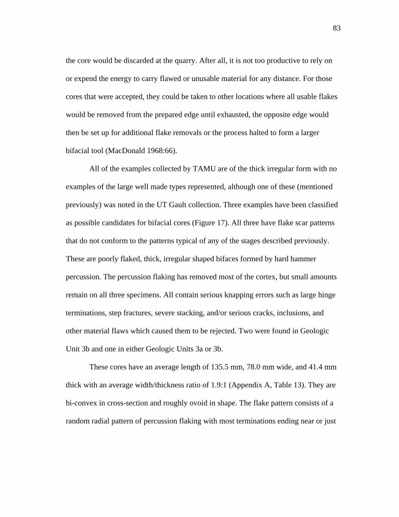
83
the core would be discarded at the quarry. After all, it is not too productive to rely on
or expend the energy to carry flawed or unusable material for any distance. For those
cores that were accepted, they could be taken to other locations where all usable flakes
would be removed from the prepared edge until exhausted, the opposite edge would
then be set up for additional flake removals or the process halted to form a larger
bifacial tool (MacDonald 1968:66).
All of the examples collected by TAMU are of the thick irregular form with no
examples of the large well made types represented, although one of these (mentioned
previously) was noted in the UT Gault collection. Three examples have been classified
as possible candidates for bifacial cores (Figure 17). All three have flake scar patterns
that do not conform to the patterns typical of any of the stages described previously.
These are poorly flaked, thick, irregular shaped bifaces formed by hard hammer
percussion. The percussion flaking has removed most of the cortex, but small amounts
remain on all three specimens. All contain serious knapping errors such as large hinge
terminations, step fractures, severe stacking, and/or serious cracks, inclusions, and
other material flaws which caused them to be rejected. Two were found in Geologic
Unit 3b and one in either Geologic Units 3a or 3b.
These cores have an average length of 135.5 mm, 78.0 mm wide, and 41.4 mm
thick with an average width/thickness ratio of 1.9:1 (Appendix A, Table 13). They are
bi-convex in cross-section and roughly ovoid in shape. The flake pattern consists of a
random radial pattern of percussion flaking with most terminations ending near or just
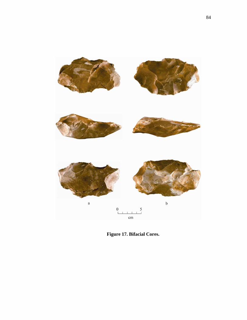
84
Figure 17. Bifacial Cores.
85
past the mid-line. Some remnant flake scars indicate that larger overface flakes may
have been removed previously. The largest flake scars are typically found on only one
of the surfaces, while the other, more convex, surface consists of smaller flaking
around the margins with some overflaking of larger scars. This marginal flaking was
performed to establish striking platforms along the edges for flake removals from the
opposite face.
The descriptions of these cores fit fairly well within the idea of the bifacial core
technology. But were they intended to be bifacial cores. Or, are they the result of some
other process? As mentioned above, all examples contain knapping errors and material
flaws, especially cracks, which probably led to their rejection. If they were never
intended to be transported, but were made to produce flakes on site, the opportunistic
flake production strategy utilizing poorer grades of material (Frison and Bradley
1980:22) may be appropriate here. However, Gault is a quarry and quarry camp
situation (Dickens and Dockall 1993:64-65) and, unless they were intended to produce
a specific type of flake, there should have been an abundance of flakes available on site
as a result of other knapping episodes.
There is an alternate explanation for these poorly flaked bifaces and that is the
idea of "novice knapping." Since this idea is often difficult to identify it is usually
overlooked. However, quarries provide excellent opportunities for knapping lessons
where material constraints are not an issue. This novice or practice flaking is already
well known from Gault. During the Archaic, the site was active in the manufacture of
Andice points, which are characterized by long barbs and very deep notches (Perino
86
1991:4; Turner and Hester 1993:71-71). Such notching requires great skill and many
flakes or fragmented bifaces that were used for this "practice notching" have been
recovered from Gault (Turner and Hester 1993:265-266). These activities would easily
result in the production of an unknown number of crude bifaces and/or other tools.
Typically, such bifaces would simply be "factored in" with other biface or tool discards
in an analysis, resulting in some bias within the final conclusion. Therefore, identifying
novice knapping, or at least recognizing it, may have an important role to play in
studies such as this.
Specialized Flakes
The approach used in this analysis is to determine a reductive process for the
Gault bifaces by separating the bifaces into appropriate reduction stages based on
identifiable technological attributes predetermined for biface manufacturing sequences
(Holmes 1890, 1891; Crabtree 1966, 1972; Muto 1971; Newcomer 1971; Collins 1975;
Flenniken 1978; Callahan 1979; Sanders 1990). These sequences usually include a
number of stages that are differentiated by the amount of cortex present and degree of
edging, thinning, and shaping combined with visible flake scar size and patterns. The
different stages are often substantiated by waste flake (debitage) analysis. The premise
behind waste flake analysis is that the size distribution of debitage within an
assemblage can reflect the stages of reduction. This is based on idea that the size of
waste flakes from bifacially flaked artifacts will decrease systematically from the initial
stages of manufacture to the final finishing stages (Newcomer 1971; Henry and
Bradley 1976; Stahle and Dunn 1982). In addition, other discrete attributes, such as
87
amount of cortex, platform angle, type, size, bulb and termination types would also be
included within such an analysis.
The use of debitage in bifacial reduction studies, in most contexts, is a sound
model and is one that has been used extensively, but it does not fully address
assemblages containing variations within the reduction process. For example, the idea
that waste flakes decrease as reduction continues is not valid within the Gault/Clovis
reduction scheme where large overface or overshot flakes, having a maximum size
limited by biface width, were being removed as late as Stage V. Although flake size is
not the only indicator used for defining reductive stages, it was believed that relying on
flake size along with their discrete attributes would not be very useful for the Gault
analysis. Thus, a slightly different approach in analyzing the debitage was necessary in
order to establish support in defining the technology for each of the different stages.
This was accomplished by selecting from the debitage those flakes considered
significant within the reduction sequence.
There are approximately 80,000 pieces of debitage that were recovered with
small flakes (less than 1/4 inch) making up the majority of the total. Each flake was
examined and the following categories were created: large flakes, problem removal
flakes, winged flakes, and overshot flakes. These categories are discussed below.
Large Flakes (N = 114)
Large flakes are useful in determining the type and form of blank utilized, how
the reductive process was initiated, and how it preceded. Some attributes for these
88
flakes (i.e., size and dorsal scar patterns) (Appendix A, Table 5) were briefly discussed
within the Stage I section. Only those flakes (whole and broken) that exceeded a
minimum size of 45 - 50 mm were chosen (Figure 7). For inclusion, the broken flakes
needed to contain the proximal end and/or estimated to be more than half of the
original flake's size. They were analyzed using the standard attributes, such as,
presence and amount of cortex, platform type, size and angle, presence and type of
bulb of percussion, dorsal scar pattern, and termination type.
Tables 5, 14 through 15 (Appendix A) provide a listing for the various
attributes for large flakes. Natural and plain platforms (Appendix A, Table 5) dominate
all three (primary, secondary, and interior) flake categories with some dihedral and
polyhedral types appearing in the secondary and interior flake categories. As would be
expected, there is little platform preparation present on the primary flakes (only some
minor grinding), while both platform isolating and grinding becomes predominant on
the secondary and interior flakes.
The averages for the platform angles (Appendix A, Table 14) are high for each
flake and platform type, averaging between 70° and 90°. Platform thickness (Appendix
A, Table 15) for natural and plain platforms average between 8 mm and 9.4 mm on the
primary flakes and decreases slightly to 5.3 - 8.0 mm on the secondary and interior
flakes. Interestingly, the width of the natural platforms remains relatively constant
(21.1 - 22.9 mm) within each flake type, while the plain platform decreases slightly
(14.8 - 15.2 mm) on secondary and interior flakes. Understandably, dihedral and
89
Polyhedral platforms are slightly smaller (17.4 - 17.7 mm) and thinner (4.4 - 5.9 mm)
on the secondary and interior flakes (Appendix A, Table 15).
Feathered terminations are the primary termination type on the secondary and
interior flakes. Hinged terminations are the second most abundant type and are evenly
distributed on the primary and secondary flakes with a slight increase on the interior
flakes (Appendix A, Table 5). Not included here are the overshot flakes which are
discussed separately below.
Although, the exact stage from which these flakes were removed cannot be
determined, the findings do support the idea that large flakes were removed, not only
during the early stage reduction, but from later stages as well. For example, it has been
determined that higher edge angles are best suited for large flake removals and
feathered type terminations (Bonnichsen (1977:170; Whittaker 1994:91). The closer to
90Ε the more the fracture, initiated from the applied force, will be directed into the
blank, rather than bending outwards, resulting in longer flakes. The dorsal scar patterns
on the secondary flakes are predominantly uni-directional with bi-directional flaking
coming in second (Appendix A, Table 5). This trend shifts on the interior flakes where
the uni-directional flaking was replaced with bi-directional and radial flaking,
indicating large flakes continued to be removed during later reduction stages.
Natural and plain platforms are indicative of little edge preparation and,
coupled with high edge angles and thick platforms, they suggest that flakes were being
removed from relatively thick and square sided edges, even after most of the cortex has
been removed. The presence of a few secondary and interior flakes having dihedral and
90
polyhedral platforms as well as platform isolating and grinding, suggest that some
flakes were carefully prepared to insure a more successful removal.
The presence of platform lipping and bulb sizes is often used as indicators for
the use of hard-hammer or soft-hammer percussion (Andrefsky 1998:114-117;
Crabtree 1972:44; Kooyman 2000:78-81). Hard-hammer flakes are usually described
as having pronounced bulbs of force, no lipping, and slightly crushed platforms
(Crabtree 1972:44), while flakes removed by soft-hammer have a lipped platform edge
and diffuse bulbs (Crabtree 1972:74). This view, however, is not universal as some
researchers have found that lipping may not always be a good indicator for soft-
hammer percussion (Patterson and Solberger 1978) as lipping and/or diffuse bulbs can
also be produced in hard-hammer percussion (Whittaker 1994:187).
Keeping these issues in mind, a study of the ventral surfaces of the large flakes
showed a strong tendency for hard-hammer use for primary and secondary flake
removals and only slightly less on interior flakes with natural, plain, and some dihedral
platforms. Soft-hammer use was highest on flakes with polyhedral platforms, but was
also used on plain and dihedral types as well. Interestingly, there are a number of flakes
having obvious (strong) bulbs with lips suggesting the possible use of a "soft" hard-
hammer percussor. Even though this was a quarry site, only one hardstone cobble that
could qualify as a hammerstone (Figure 18) was recovered from the Clovis levels. This
particular specimen is an elongated quartzite cobble that has some crushing on both of
its ends. In addition to this crushing, one end has been fractured at an angle that is
reminiscent of a bit used for a gouge. Although it can be argued that the crushing on
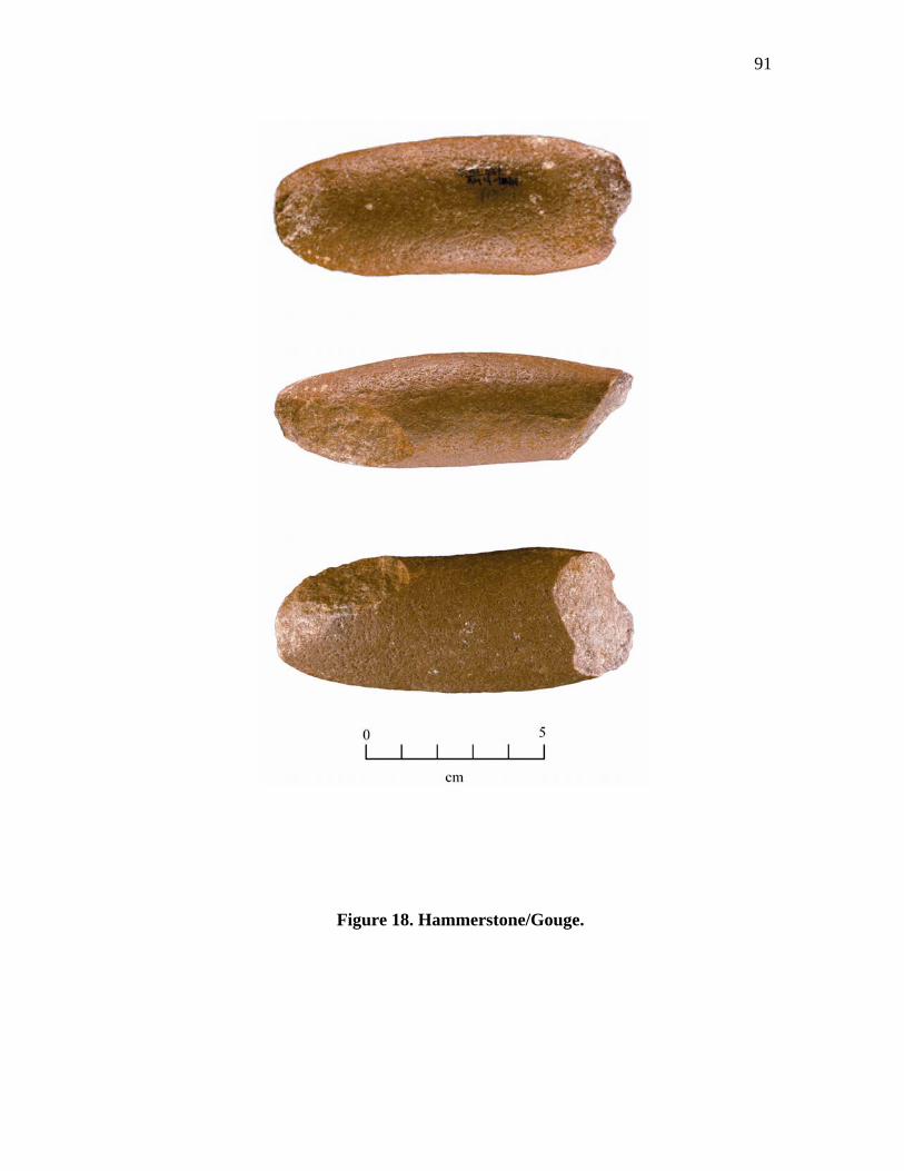
91
Figure 18. Hammerstone/Gouge.
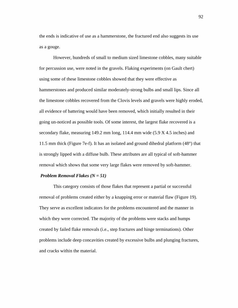
92
the ends is indicative of use as a hammerstone, the fractured end also suggests its use
as a gouge.
However, hundreds of small to medium sized limestone cobbles, many suitable
for percussion use, were noted in the gravels. Flaking experiments (on Gault chert)
using some of these limestone cobbles showed that they were effective as
hammerstones and produced similar moderately-strong bulbs and small lips. Since all
the limestone cobbles recovered from the Clovis levels and gravels were highly eroded,
all evidence of battering would have been removed, which initially resulted in their
going un-noticed as possible tools. Of some interest, the largest flake recovered is a
secondary flake, measuring 149.2 mm long, 114.4 mm wide (5.9 X 4.5 inches) and
11.5 mm thick (Figure 7e-f). It has an isolated and ground dihedral platform (48°) that
is strongly lipped with a diffuse bulb. These attributes are all typical of soft-hammer
removal which shows that some very large flakes were removed by soft-hammer.
Problem Removal Flakes (N = 51)
This category consists of those flakes that represent a partial or successful
removal of problems created either by a knapping error or material flaw (Figure 19).
They serve as excellent indicators for the problems encountered and the manner in
which they were corrected. The majority of the problems were stacks and humps
created by failed flake removals (i.e., step fractures and hinge terminations). Other
problems include deep concavities created by excessive bulbs and plunging fractures,
and cracks within the material.
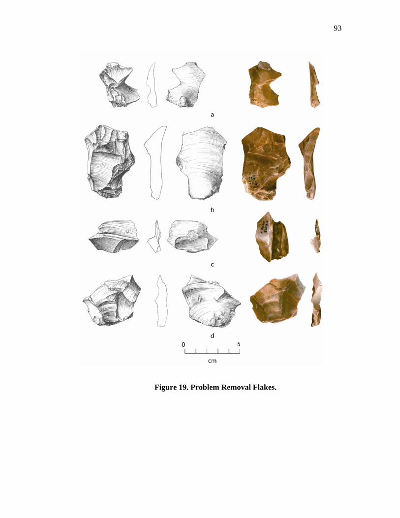
93
Figure 19. Problem Removal Flakes.
94
The stacks and humps were most often created by multiple flaking attempts to
clear an earlier failed flake, crack, or remove surface irregularities. Insufficient force of
blow, excessive striking angle, and cracks are some of the causes for flakes to
terminate abruptly in a right angle. Subsequent flaking into these termination points
often fails creating a "mass" of material to build up. As this mass builds up, flakes
driven toward it will often stop and break at its edge resulting in an additional build-up
of material. In addition, some of these flakes will plunge or hinge often creating deep
concavities at the point of termination.
The idea behind correcting these problems is to run a flake under the mass,
hump, crack, or depression with the intent that the fracture will pass under the problem
without stopping. The Gault knappers were successful at "clearing" many of these
problems. The flakes produced to remove these problems are thick with moderately
strong to strong bulbs (only one contained a lip), indicating removal by hard-hammer
percussion. Most of the platforms are plain (75%), but some were natural (25%).
Platform thickness ranges between 2.3mm and 13.6mm, and platform angles range
between 53° and 98° with most nearer to 90°.
Several problem removal flakes are hinges formed by two opposing flakes that
terminated short of each other creating a railroad rail-like ridge between the two
termination points. One of these was removed via a large flake; the other had only the
ridge removed. Two other flakes contain plunging hinge fractures on their distal ends
which also retain portions of the blank’s lateral edge. It was determined that the
direction of the plunging flake scars originated on the opposite edge and were flaked
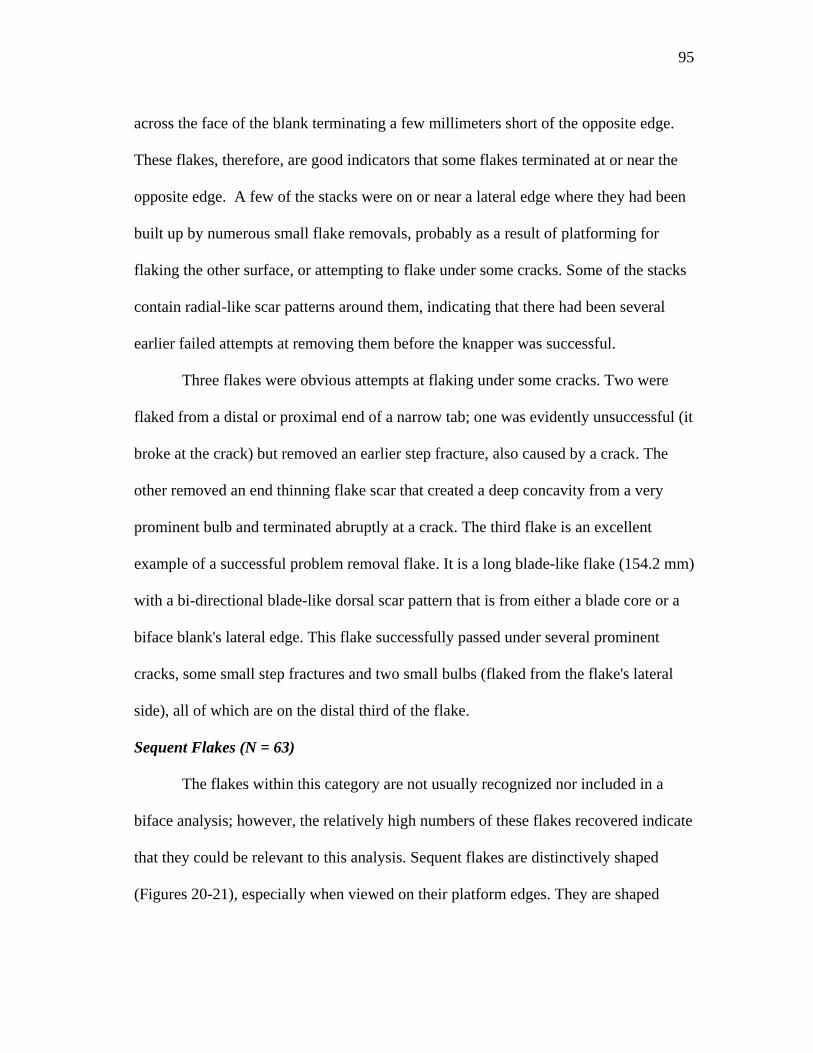
95
across the face of the blank terminating a few millimeters short of the opposite edge.
These flakes, therefore, are good indicators that some flakes terminated at or near the
opposite edge. A few of the stacks were on or near a lateral edge where they had been
built up by numerous small flake removals, probably as a result of platforming for
flaking the other surface, or attempting to flake under some cracks. Some of the stacks
contain radial-like scar patterns around them, indicating that there had been several
earlier failed attempts at removing them before the knapper was successful.
Three flakes were obvious attempts at flaking under some cracks. Two were
flaked from a distal or proximal end of a narrow tab; one was evidently unsuccessful (it
broke at the crack) but removed an earlier step fracture, also caused by a crack. The
other removed an end thinning flake scar that created a deep concavity from a very
prominent bulb and terminated abruptly at a crack. The third flake is an excellent
example of a successful problem removal flake. It is a long blade-like flake (154.2 mm)
with a bi-directional blade-like dorsal scar pattern that is from either a blade core or a
biface blank's lateral edge. This flake successfully passed under several prominent
cracks, some small step fractures and two small bulbs (flaked from the flake's lateral
side), all of which are on the distal third of the flake.
Sequent Flakes (N = 63)
The flakes within this category are not usually recognized nor included in a
biface analysis; however, the relatively high numbers of these flakes recovered indicate
that they could be relevant to this analysis. Sequent flakes are distinctively shaped
(Figures 20-21), especially when viewed on their platform edges. They are shaped
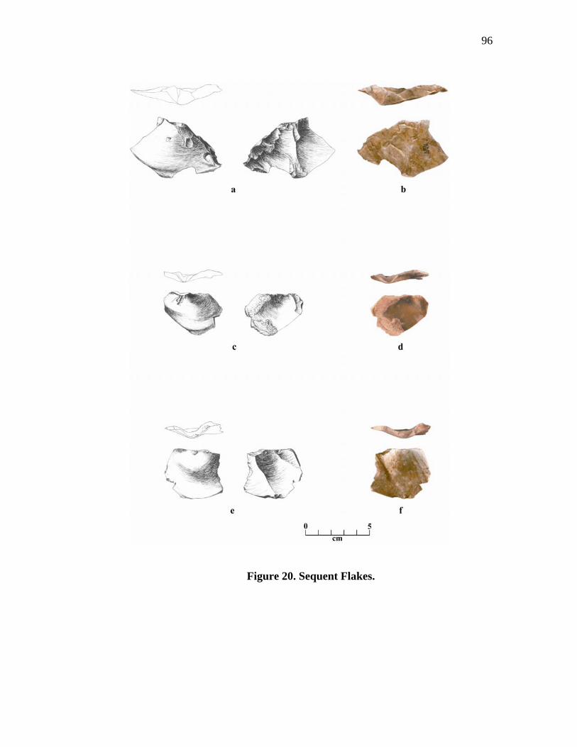
96
Figure 20. Sequent Flakes.
97
Figure 21. Sequent Flakes II.
98
much like a "V" where the platform angles sharply down into a steep depression while
the edges flare up and outward forming a winged shape. The depth of the "V" varies
and is directly related to their sequence of manufacture.
The various attributes for the sequent flakes are provided in tables 16 through
18 (Appendix A). Although they are often as long as they are wide, they are usually
wider than long with widths ranging up to 37 mm (1.5 inches). The dorsal surfaces
adjacent to the central depression may or may not contain cortex, indicating some
production prior and after complete cortical removal has been accomplished. The
dorsal flake scar patters may be uni-directional, bi-directional or radial, but most are
uni-directional with 56% for primary flakes and 81% for secondary flakes (Appendix
A, Tables 16-17).
The platform angles are steep with 78.3° for secondary flakes and 72.4° for
interior flakes (Appendix A, Table 17). The platforms vary, but most are plain having
little preparation with 53% for primary flakes and 65% for secondary flakes. Platform
thickness (Appendix A, Table 18) varies with the size of the flake, but most are thick
with 63% exceeding 3.0 mm for primary flakes and 80% exceeding 3.0 mm for
secondary flakes.
These flakes were produced by a repetitive flaking from the same point. The
flaking sequence began by knocking a small flake from the flat surface of a tab or
blank using light hard-hammer percussion. Subsequent flakes were removed by
striking directly below the point of impact struck by the previous removal. Each flake
99
removed is slightly larger, with its corresponding negative bulb scars and respective
bulbs becoming larger and more prominent than those from previous flake.
The term "sequent flake" was first used to describe a distinct flake type used as
a scraper found at Amistad Reservoir in Val Verde County, Texas (Nunley et. al.
1965:74). These flakes were produced by the repetitive removal of flakes from
elongated nodules, much like a loaf of bread. Each flake was struck at the same point
directly behind the previous one which resulted in producing a bulb that increased in
depth with each subsequent flake produced. Once, however, the bulb became to large
or other material factors became evident that could affect successful flake removal, the
point of impact was shifted to another point on the nodule's surface.
Another similar type of flake has been identified within the lithic debitage of
the Mousterian Levallois, Egyptian Neolithic, and the Near Eastern Bronze Age of the
Old World and is believed to have been produced during some forms of platform
preparation. This is the proximal (butt) end of a flake, formed by the removal of two
exactly superimposed flakes, that when viewed end-on, appears "winged" (Inizan et. al.
1992:80-82).
Frison and Bradley (1980:18,21) describe similar flakes that were produced
during discoidal core manufacture at the Hanson site. These are described as flakes
with thick, wide platforms, a simple flake scar pattern, low flake scar counts, and a
triangular longitudinal cross-section. Although considered as part of the discoidal core
manufacture at the Hanson site, Frison and Bradley recognized that similar flakes also
100
occur in other flake production systems, especially during preliminary stages of
manufacture.
Experimental replications showed that these flakes could be produced as part of
a process for setting up and isolating platforms. Several members of the Belton Knap-
in, a gathering of flint knappers first established by J. B. Solberger in the late 1960's,
were asked to use this method during bifacial thinning. The result was that the
platforms produced enabled large flakes, many terminating near or over the opposite
edge to be easily removed suggesting a suitable use in biface reduction in addition to
blade manufacture.
As mentioned previously, each flake produced resulted in a larger, more
prominent bulb with the lateral edges of the flake flaring up and over onto the tab or
blank's surface. When two widely spaced sets of these flakes are removed, a prominent
and isolated "hump" is formed between them. The edge of this hump can then be
modified into a raised and well-isolated platform. A single set may only be necessary if
the surface already contains some undulations or concavities. A drawback could occur
if the sets are flaked too close together or if too many flakes are removed which would
begin to overflake and decrease the height of the hump. The dorsal surface of these
humps often angle into the blank's mass, whereby minor flaking (of this surface) will
easily flatten the surface or, in the case of blade production, produce a desired striking
angle. The result is a pronounced platform that is very effective in removing large
flakes. Although no such flake removal patterns were noted on any of the bifaces
analyzed, some were evident on a few of the large and overshot flakes. This is not
101
surprising, as any such evidence would easily be removed during bifacial edge
trimming or additional platforming. They were noted, however, on many of the blade
cores recovered where they may have been utilized more extensively for blade
production.
Overshot Flakes (N = 185)
Recent interpretations of Clovis lithic technology have included the use of
overshot or outrepassé flaking as a principal reduction technique (Bradley 1982, 1991,
1993; Morrow 1996; Johnson 1993; Collins 1999a, 1999b; Frison and Bradley 1999;
Kooyman 2000; Dennis Stanford, personal communication 2003). Previous
interpretations have recognized the presence of overshot flaking within the Clovis
manufacturing sequence but considered it's presence as a knapping error and not as an
intended strategy (Callahan 1979; Sanders 1983; 1990; Verrey 1986; Patten 1999).
Indeed, most researchers and modern knappers consider overshot flakes as a flaking
mistake often requiring substantial edge reshaping or resulting in rejection of the
preform/blank. In contemplation of these issues, the high number of overshot flakes
recovered from Gault provides an excellent opportunity to analyze their place within
the Clovis lithic technology.
As discussed briefly in the bifacial stage reduction sequences, the overshot
flakes recovered were divided into two types (i.e., partial overshots and full overshots).
Of the 185 overshot flakes recovered, 121 were classified as partial and 64 as full
overshots (Appendix A, Table 3). The partial type (Figure 5e-j) occurs on square sided
core/blanks and is those flakes that fracture across the surface of the core/blank,
102
plunging over the opposite edge, and terminating on the lateral edge. These flakes
retain part of the "vertical" lateral edge without removing any of the ventral surface.
Full overshots (Figure 5 a-d) are the more "classic" type that fracture across the surface
of a core/blank whose dorsal and ventral surfaces have converged, plunging over the
opposite edge retaining part of both surfaces.
Overshot flakes were recovered from within both geologic units 3a and 3b. Full
overshots were split evenly between the two units with 31 from Geologic Unit 3a and
28 from Geologic Unit 3b, and the remainder from either geologic units3a or 3b.
Partial overshots, however, were much more abundant in Geologic Unit 3a with 74,
than in Geologic Unit 3b which totaled only 32, with 13 coming from either geologic
units 3a or 3b (Appendix A, Table 2). These findings indicate a continued use of this
strategy throughout the Clovis occupation.
Partial overshot flakes were flaked across the surface of thick, square or vertical
sided core/blanks, often at an oblique angle, but some were removed across the
proximal and distal corners. These flakes are generally thick with midsections
averaging 12.0 mm for primary flakes, 11.1 mm for secondary flakes, and 10.8 mm for
interior flakes. Seventy-five of the 121 partial overshot flakes are complete and 43% of
these have platforms that exhibit grinding and 27% have isolated platforms. Platform
types include natural, plain, dihedral, and polyhedral with the natural and plain types
being the most common (Appendix A, tables 4, 19). Total platform angles (all platform
types) average 78.5° for the primary flakes, 82.0° for secondary flakes, and 75.9° for
the interior flakes. Platform thickness (all flake types) is highest for natural platforms
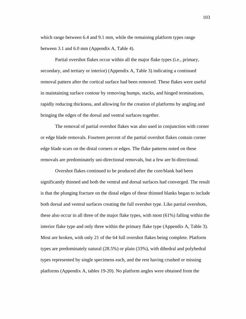
103
which range between 6.4 and 9.1 mm, while the remaining platform types range
between 3.1 and 6.0 mm (Appendix A, Table 4).
Partial overshot flakes occur within all the major flake types (i.e., primary,
secondary, and tertiary or interior) (Appendix A, Table 3) indicating a continued
removal pattern after the cortical surface had been removed. These flakes were useful
in maintaining surface contour by removing humps, stacks, and hinged terminations,
rapidly reducing thickness, and allowing for the creation of platforms by angling and
bringing the edges of the dorsal and ventral surfaces together.
The removal of partial overshot flakes was also used in conjunction with corner
or edge blade removals. Fourteen percent of the partial overshot flakes contain corner
edge blade scars on the distal corners or edges. The flake patterns noted on these
removals are predominately uni-directional removals, but a few are bi-directional.
Overshot flakes continued to be produced after the core/blank had been
significantly thinned and both the ventral and dorsal surfaces had converged. The result
is that the plunging fracture on the distal edges of these thinned blanks began to include
both dorsal and ventral surfaces creating the full overshot type. Like partial overshots,
these also occur in all three of the major flake types, with most (61%) falling within the
interior flake type and only three within the primary flake type (Appendix A, Table 3).
Most are broken, with only 21 of the 64 full overshot flakes being complete. Platform
types are predominately natural (28.5%) or plain (33%), with dihedral and polyhedral
types represented by single specimens each, and the rest having crushed or missing
platforms (Appendix A, tables 19-20). No platform angles were obtained from the
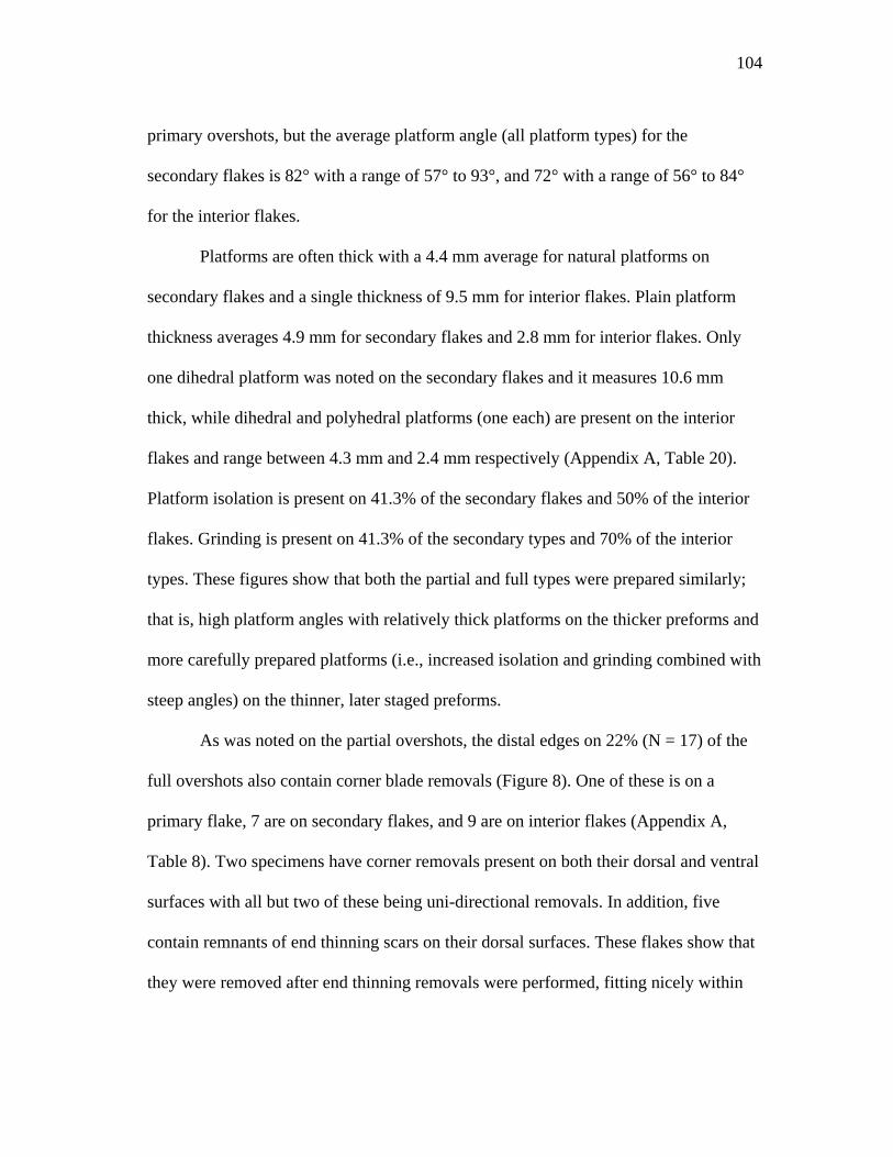
104
primary overshots, but the average platform angle (all platform types) for the
secondary flakes is 82° with a range of 57° to 93°, and 72° with a range of 56° to 84°
for the interior flakes.
Platforms are often thick with a 4.4 mm average for natural platforms on
secondary flakes and a single thickness of 9.5 mm for interior flakes. Plain platform
thickness averages 4.9 mm for secondary flakes and 2.8 mm for interior flakes. Only
one dihedral platform was noted on the secondary flakes and it measures 10.6 mm
thick, while dihedral and polyhedral platforms (one each) are present on the interior
flakes and range between 4.3 mm and 2.4 mm respectively (Appendix A, Table 20).
Platform isolation is present on 41.3% of the secondary flakes and 50% of the interior
flakes. Grinding is present on 41.3% of the secondary types and 70% of the interior
types. These figures show that both the partial and full types were prepared similarly;
that is, high platform angles with relatively thick platforms on the thicker preforms and
more carefully prepared platforms (i.e., increased isolation and grinding combined with
steep angles) on the thinner, later staged preforms.
As was noted on the partial overshots, the distal edges on 22% (N = 17) of the
full overshots also contain corner blade removals (Figure 8). One of these is on a
primary flake, 7 are on secondary flakes, and 9 are on interior flakes (Appendix A,
Table 8). Two specimens have corner removals present on both their dorsal and ventral
surfaces with all but two of these being uni-directional removals. In addition, five
contain remnants of end thinning scars on their dorsal surfaces. These flakes show that
they were removed after end thinning removals were performed, fitting nicely within
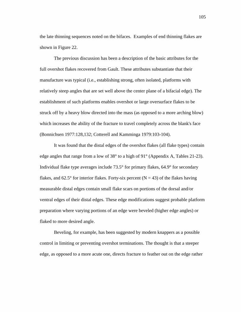
105
the late thinning sequences noted on the bifaces. Examples of end thinning flakes are
shown in Figure 22.
The previous discussion has been a description of the basic attributes for the
full overshot flakes recovered from Gault. These attributes substantiate that their
manufacture was typical (i.e., establishing strong, often isolated, platforms with
relatively steep angles that are set well above the center plane of a bifacial edge). The
establishment of such platforms enables overshot or large oversurface flakes to be
struck off by a heavy blow directed into the mass (as opposed to a more arching blow)
which increases the ability of the fracture to travel completely across the blank's face
(Bonnichsen 1977:128,132; Cotterell and Kamminga 1979:103-104).
It was found that the distal edges of the overshot flakes (all flake types) contain
edge angles that range from a low of 38° to a high of 91° (Appendix A, Tables 21-23).
Individual flake type averages include 73.5° for primary flakes, 64.9° for secondary
flakes, and 62.5° for interior flakes. Forty-six percent (N = 43) of the flakes having
measurable distal edges contain small flake scars on portions of the dorsal and/or
ventral edges of their distal edges. These edge modifications suggest probable platform
preparation where varying portions of an edge were beveled (higher edge angles) or
flaked to more desired angle.
Beveling, for example, has been suggested by modern knappers as a possible
control in limiting or preventing overshot terminations. The thought is that a steeper
edge, as opposed to a more acute one, directs fracture to feather out on the edge rather
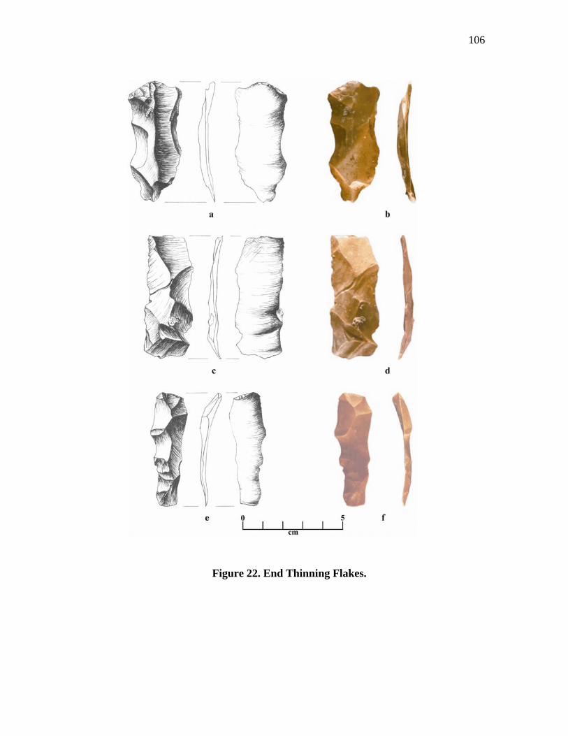
106
Figure 22. End Thinning Flakes.
107
than in a plunging fracture. The high number of overshots with distal edge angles over
60° (an approximation) suggests a possible use of this technique.
Another reason for higher edge angles is proposed by Patten (1999:93-94)
where he describes an experimental method for early stage Clovis biface manufacture
involving the beveling, battering, and abrading of the entire edge prior to flaking.
Flaking from these edges is designed to flatten each surface with a minimum of flake
removals terminating near the far edge. Although there is little to no battering or
abrasion observed on the distal edges of the Gault examples, the edge beveling (angles
exceeding 60°) is similar to Patten's method.
Another experiment by Dibble and Whittaker (1981) found that platform angles
between 50° and 70° (with no appreciable difference between them) were optimum for
producing large flakes. Dibble and Whittaker's angles fit well within the distal edge
angle range found on the Gault overshot flakes. This supports the idea that large
portions of the Gault biface's edges were being set up as platforms for large flake
removals and that each edge was set up prior to each surface's flaking sequence.
There is no question that the production of partial overshot flakes was intended.
The thickness of the blank's edge prevented the fracture from plunging to the opposite
face and limited the amount of edge removed. However, full overshot removals
performed on thinner blanks are more difficult to control and often remove more of the
edge than intended. The question then is how much of the edge could be successfully
removed without causing failure? To help determine this, the Gault overshots were
used to calculate the amount of distal edge loss removed with each flake.
108
Twenty-one of the full overshot flakes were complete enough to determine the
amount of the distal edge removed with each flake. A percentage of the distal edge loss
was calculated for each flake by dividing the width of edge present on the ventral face
by the length of the ventral fractured surface measured from the platform to the
fractured edge (Appendix A, Table 24). Since these flakes were often detached in an
irregular manner, ventral edge loss sometimes varied. Therefore, the measurements
taken were averaged on those having close width variances or ranges on those with
extreme variances. The latter (ranges) were considered due to the flaking direction of
many overshots that angled across the biface resulting in a wider edge loss toward one
side of the flakes width. These points could have been toward one end of the biface
where wider edge loss may not have been as critical as that occurring in a more medial
portion. The results of these calculations showed a ventral edge loss ranging between
6% and 56% with an average of 27%. This suggests that, on average, as much as one-
quarter of the edge was removed with each flake. For comparison, an average of 20%
was noted on two complete Archaic overshot flakes (the only complete flakes out of 14
total recovered).
The widths of the Stage IV and V Gault bifaces having overshot flake scars
were compared to the two Stage VI specimens that broke during the final fluting
process. It was believed that the two Stage VI bifaces represent the intended width for
finished points (prior to final edge clean-up), and the difference in width between these
and the Stage IV and V bifaces would provide the amount of edge reduction that
occurred between the stages. In addition, it was determined that several of the Stage IV
109
and V bifaces with overshot flake scars contain edges that had little, if any, edge
removal after the overshot had been removed. The amount of edge loss on these was
determined by measuring the difference between the original edge and the overshot
scar edge. From these calculations, it was determined that a maximum of 10% to 15%
edge loss per removal (limited to two removals per edge) would be an acceptable edge
reduction. This is not to dismiss the idea that a single edge loss of 20% or more from a
large biface could not be saved if the remaining removals were within an acceptable
edge loss range or no further overshots were removed. Looking at these figures, it was
found that only four of the twenty-one complete overshots contain a 15% or less edge
loss.
In addition to the complete flakes (used to compute the above averages), there
are an additional 45 broken examples. Although broken, the distal edges are present on
all specimens. Therefore, it was believed that a review of the fractured flakes was
necessary in determining edge loss. The problem, however, with these flakes is that the
exact percentage of ventral edge loss cannot be determined due to their incomplete
state.
The ventral edge loss on the complete flakes with 15% or less edge was all
found to be 10 mm or less. Twenty-four (53%) of 45 broken flakes were found to have
an edge loss of 10 mm or less. If one accepts the 10 mm figure as representative of
acceptable ventral edge loss, then it suggests that approximately half of the broken full
overshot flakes recovered may represent acceptable edge losses or successful overshot
removals. It should be mentioned, however, that this conclusion is totally dependant
110
upon actual flake length and that two of the complete flakes with measured ventral
edge losses less than 10 mm also have edge losses of 21% and 24%, respectively.
The results of the overshot flake study support the idea that overshot flaking
can be a successful strategy. The data shows that approximately 50% of the overshots
may have been acceptable removals. However, these figures do not prove whether it
was an intentional strategy or not, although the high number of overshot flakes
recovered and the overshot scars present on many of the bifaces imply that it was a
common occurrence. In all probability, the intended flaking strategy was to flatten and
smooth the biface surface by removing large flakes from across the width of a
blank/preform that terminate somewhere near the opposite edge. The best-case scenario
would be for a flake to terminate either on the edge or plunge slightly over it. Of
course, it takes an in depth knowledge of flake fracture mechanics as well as
possessing a great deal of skill to be successful in either case.
Summary
The immediate region of the Gault site contains a number of natural resources
that were considered valuable by prehistoric occupations. One of these resources is the
presence of a variety of Edwards Chert, some of an excellent quality. Although the
better chert has been heavily exploited in recent times by modern flintknappers, the
extensive quantities of flake debris present throughout the site, indicate that in the past
the higher quality chert had occurred there in large quantities. The better grades of
chert have a flaked surface that is slick and shiny and are a light gray color with
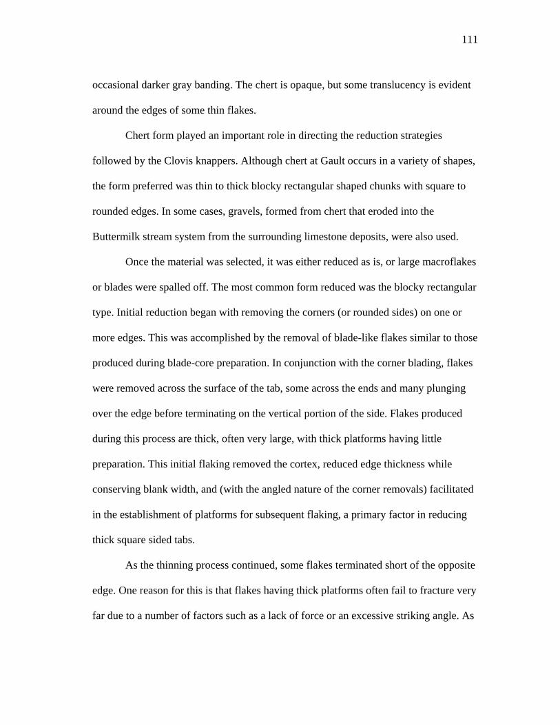
111
occasional darker gray banding. The chert is opaque, but some translucency is evident
around the edges of some thin flakes.
Chert form played an important role in directing the reduction strategies
followed by the Clovis knappers. Although chert at Gault occurs in a variety of shapes,
the form preferred was thin to thick blocky rectangular shaped chunks with square to
rounded edges. In some cases, gravels, formed from chert that eroded into the
Buttermilk stream system from the surrounding limestone deposits, were also used.
Once the material was selected, it was either reduced as is, or large macroflakes
or blades were spalled off. The most common form reduced was the blocky rectangular
type. Initial reduction began with removing the corners (or rounded sides) on one or
more edges. This was accomplished by the removal of blade-like flakes similar to those
produced during blade-core preparation. In conjunction with the corner blading, flakes
were removed across the surface of the tab, some across the ends and many plunging
over the edge before terminating on the vertical portion of the side. Flakes produced
during this process are thick, often very large, with thick platforms having little
preparation. This initial flaking removed the cortex, reduced edge thickness while
conserving blank width, and (with the angled nature of the corner removals) facilitated
in the establishment of platforms for subsequent flaking, a primary factor in reducing
thick square sided tabs.
As the thinning process continued, some flakes terminated short of the opposite
edge. One reason for this is that flakes having thick platforms often fail to fracture very
far due to a number of factors such as a lack of force or an excessive striking angle. As
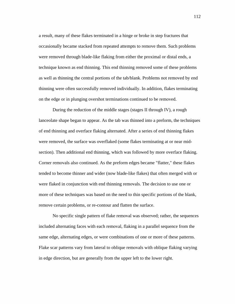
112
a result, many of these flakes terminated in a hinge or broke in step fractures that
occasionally became stacked from repeated attempts to remove them. Such problems
were removed through blade-like flaking from either the proximal or distal ends, a
technique known as end thinning. This end thinning removed some of these problems
as well as thinning the central portions of the tab/blank. Problems not removed by end
thinning were often successfully removed individually. In addition, flakes terminating
on the edge or in plunging overshot terminations continued to be removed.
During the reduction of the middle stages (stages II through IV), a rough
lanceolate shape began to appear. As the tab was thinned into a preform, the techniques
of end thinning and overface flaking alternated. After a series of end thinning flakes
were removed, the surface was overflaked (some flakes terminating at or near mid-
section). Then additional end thinning, which was followed by more overface flaking.
Corner removals also continued. As the preform edges became "flatter," these flakes
tended to become thinner and wider (now blade-like flakes) that often merged with or
were flaked in conjunction with end thinning removals. The decision to use one or
more of these techniques was based on the need to thin specific portions of the blank,
remove certain problems, or re-contour and flatten the surface.
No specific single pattern of flake removal was observed; rather, the sequences
included alternating faces with each removal, flaking in a parallel sequence from the
same edge, alternating edges, or were combinations of one or more of these patterns.
Flake scar patterns vary from lateral to oblique removals with oblique flaking varying
in edge direction, but are generally from the upper left to the lower right.
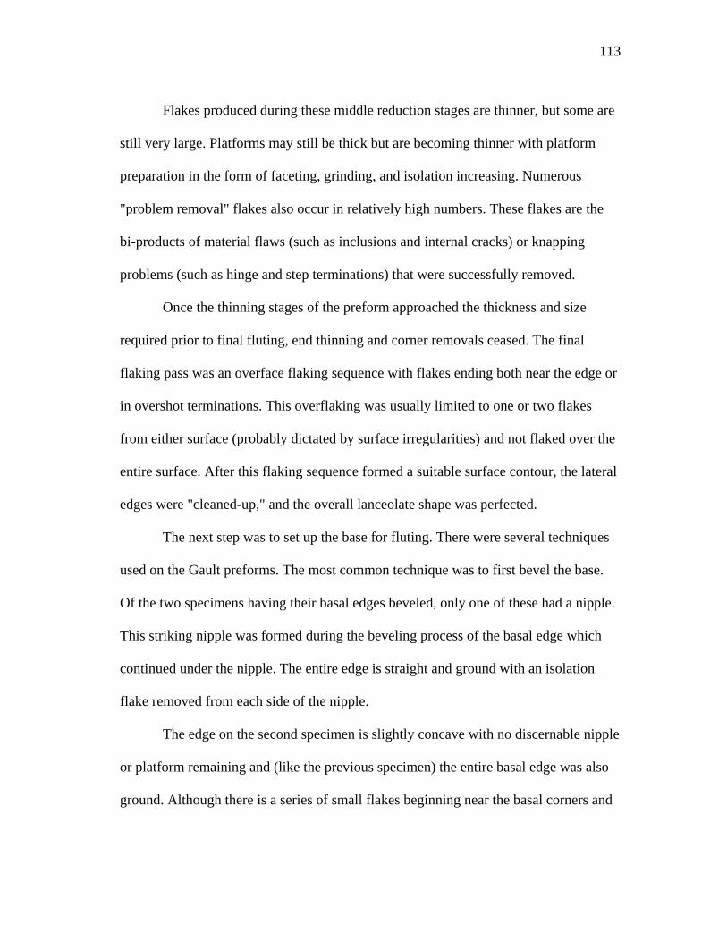
113
Flakes produced during these middle reduction stages are thinner, but some are
still very large. Platforms may still be thick but are becoming thinner with platform
preparation in the form of faceting, grinding, and isolation increasing. Numerous
"problem removal" flakes also occur in relatively high numbers. These flakes are the
bi-products of material flaws (such as inclusions and internal cracks) or knapping
problems (such as hinge and step terminations) that were successfully removed.
Once the thinning stages of the preform approached the thickness and size
required prior to final fluting, end thinning and corner removals ceased. The final
flaking pass was an overface flaking sequence with flakes ending both near the edge or
in overshot terminations. This overflaking was usually limited to one or two flakes
from either surface (probably dictated by surface irregularities) and not flaked over the
entire surface. After this flaking sequence formed a suitable surface contour, the lateral
edges were "cleaned-up," and the overall lanceolate shape was perfected.
The next step was to set up the base for fluting. There were several techniques
used on the Gault preforms. The most common technique was to first bevel the base.
Of the two specimens having their basal edges beveled, only one of these had a nipple.
This striking nipple was formed during the beveling process of the basal edge which
continued under the nipple. The entire edge is straight and ground with an isolation
flake removed from each side of the nipple.
The edge on the second specimen is slightly concave with no discernable nipple
or platform remaining and (like the previous specimen) the entire basal edge was also
ground. Although there is a series of small flakes beginning near the basal corners and
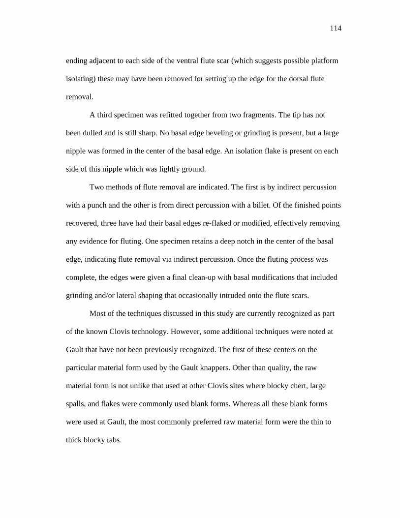
114
ending adjacent to each side of the ventral flute scar (which suggests possible platform
isolating) these may have been removed for setting up the edge for the dorsal flute
removal.
A third specimen was refitted together from two fragments. The tip has not
been dulled and is still sharp. No basal edge beveling or grinding is present, but a large
nipple was formed in the center of the basal edge. An isolation flake is present on each
side of this nipple which was lightly ground.
Two methods of flute removal are indicated. The first is by indirect percussion
with a punch and the other is from direct percussion with a billet. Of the finished points
recovered, three have had their basal edges re-flaked or modified, effectively removing
any evidence for fluting. One specimen retains a deep notch in the center of the basal
edge, indicating flute removal via indirect percussion. Once the fluting process was
complete, the edges were given a final clean-up with basal modifications that included
grinding and/or lateral shaping that occasionally intruded onto the flute scars.
Most of the techniques discussed in this study are currently recognized as part
of the known Clovis technology. However, some additional techniques were noted at
Gault that have not been previously recognized. The first of these centers on the
particular material form used by the Gault knappers. Other than quality, the raw
material form is not unlike that used at other Clovis sites where blocky chert, large
spalls, and flakes were commonly used blank forms. Whereas all these blank forms
were used at Gault, the most commonly preferred raw material form were the thin to
thick blocky tabs.
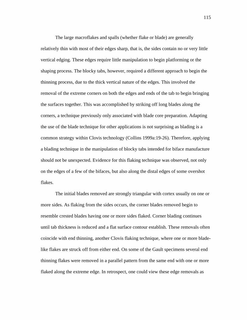
115
The large macroflakes and spalls (whether flake or blade) are generally
relatively thin with most of their edges sharp, that is, the sides contain no or very little
vertical edging. These edges require little manipulation to begin platforming or the
shaping process. The blocky tabs, however, required a different approach to begin the
thinning process, due to the thick vertical nature of the edges. This involved the
removal of the extreme corners on both the edges and ends of the tab to begin bringing
the surfaces together. This was accomplished by striking off long blades along the
corners, a technique previously only associated with blade core preparation. Adapting
the use of the blade technique for other applications is not surprising as blading is a
common strategy within Clovis technology (Collins 1999a:19-26). Therefore, applying
a blading technique in the manipulation of blocky tabs intended for biface manufacture
should not be unexpected. Evidence for this flaking technique was observed, not only
on the edges of a few of the bifaces, but also along the distal edges of some overshot
flakes.
The initial blades removed are strongly triangular with cortex usually on one or
more sides. As flaking from the sides occurs, the corner blades removed begin to
resemble crested blades having one or more sides flaked. Corner blading continues
until tab thickness is reduced and a flat surface contour establish. These removals often
coincide with end thinning, another Clovis flaking technique, where one or more blade-
like flakes are struck off from either end. On some of the Gault specimens several end
thinning flakes were removed in a parallel pattern from the same end with one or more
flaked along the extreme edge. In retrospect, one could view these edge removals as
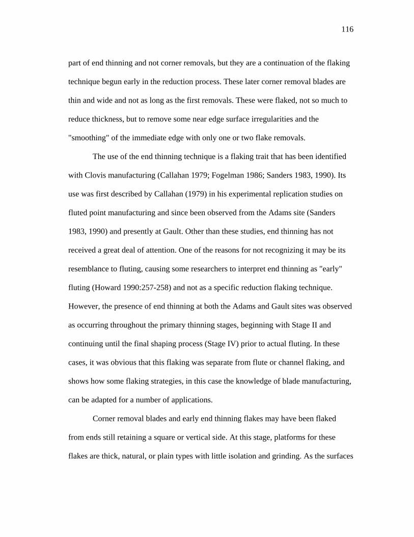
116
part of end thinning and not corner removals, but they are a continuation of the flaking
technique begun early in the reduction process. These later corner removal blades are
thin and wide and not as long as the first removals. These were flaked, not so much to
reduce thickness, but to remove some near edge surface irregularities and the
"smoothing" of the immediate edge with only one or two flake removals.
The use of the end thinning technique is a flaking trait that has been identified
with Clovis manufacturing (Callahan 1979; Fogelman 1986; Sanders 1983, 1990). Its
use was first described by Callahan (1979) in his experimental replication studies on
fluted point manufacturing and since been observed from the Adams site (Sanders
1983, 1990) and presently at Gault. Other than these studies, end thinning has not
received a great deal of attention. One of the reasons for not recognizing it may be its
resemblance to fluting, causing some researchers to interpret end thinning as "early"
fluting (Howard 1990:257-258) and not as a specific reduction flaking technique.
However, the presence of end thinning at both the Adams and Gault sites was observed
as occurring throughout the primary thinning stages, beginning with Stage II and
continuing until the final shaping process (Stage IV) prior to actual fluting. In these
cases, it was obvious that this flaking was separate from flute or channel flaking, and
shows how some flaking strategies, in this case the knowledge of blade manufacturing,
can be adapted for a number of applications.
Corner removal blades and early end thinning flakes may have been flaked
from ends still retaining a square or vertical side. At this stage, platforms for these
flakes are thick, natural, or plain types with little isolation and grinding. As the surfaces
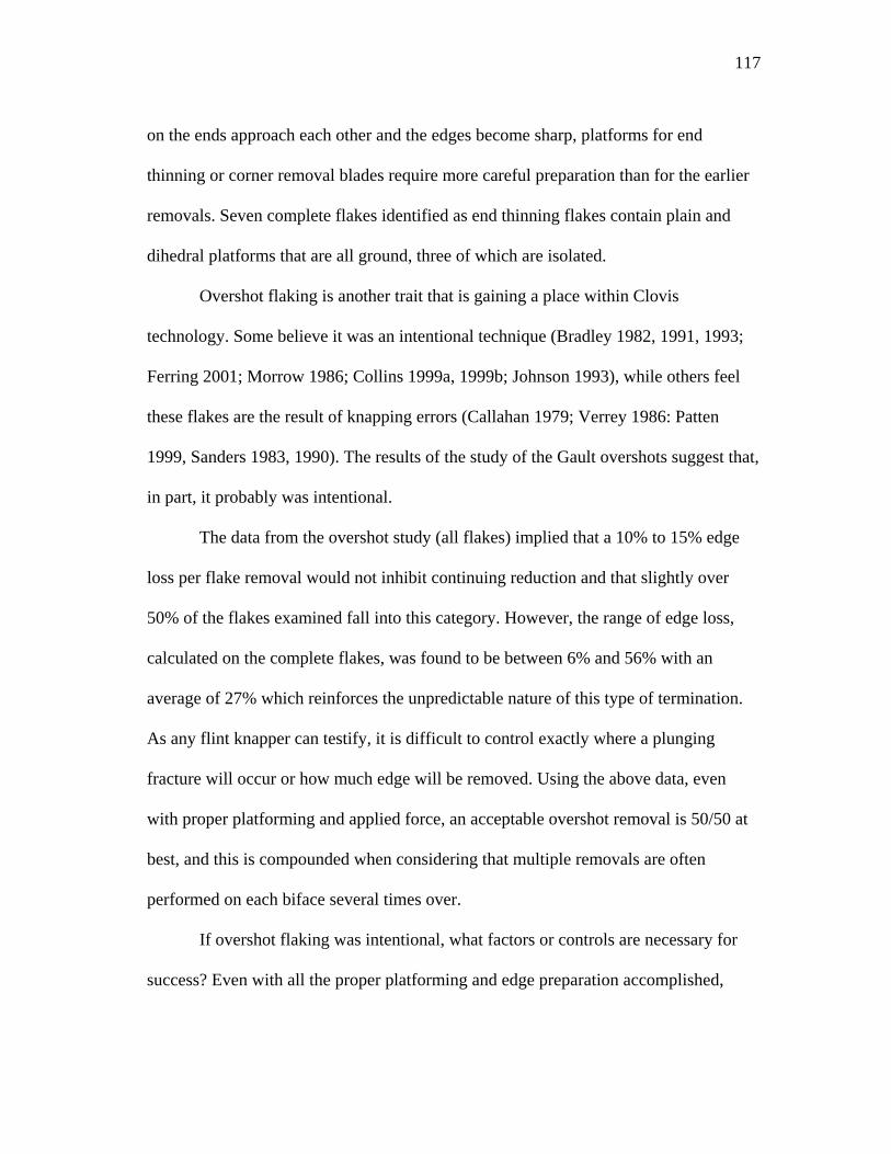
117
on the ends approach each other and the edges become sharp, platforms for end
thinning or corner removal blades require more careful preparation than for the earlier
removals. Seven complete flakes identified as end thinning flakes contain plain and
dihedral platforms that are all ground, three of which are isolated.
Overshot flaking is another trait that is gaining a place within Clovis
technology. Some believe it was an intentional technique (Bradley 1982, 1991, 1993;
Ferring 2001; Morrow 1986; Collins 1999a, 1999b; Johnson 1993), while others feel
these flakes are the result of knapping errors (Callahan 1979; Verrey 1986: Patten
1999, Sanders 1983, 1990). The results of the study of the Gault overshots suggest that,
in part, it probably was intentional.
The data from the overshot study (all flakes) implied that a 10% to 15% edge
loss per flake removal would not inhibit continuing reduction and that slightly over
50% of the flakes examined fall into this category. However, the range of edge loss,
calculated on the complete flakes, was found to be between 6% and 56% with an
average of 27% which reinforces the unpredictable nature of this type of termination.
As any flint knapper can testify, it is difficult to control exactly where a plunging
fracture will occur or how much edge will be removed. Using the above data, even
with proper platforming and applied force, an acceptable overshot removal is 50/50 at
best, and this is compounded when considering that multiple removals are often
performed on each biface several times over.
If overshot flaking was intentional, what factors or controls are necessary for
success? Even with all the proper platforming and edge preparation accomplished,
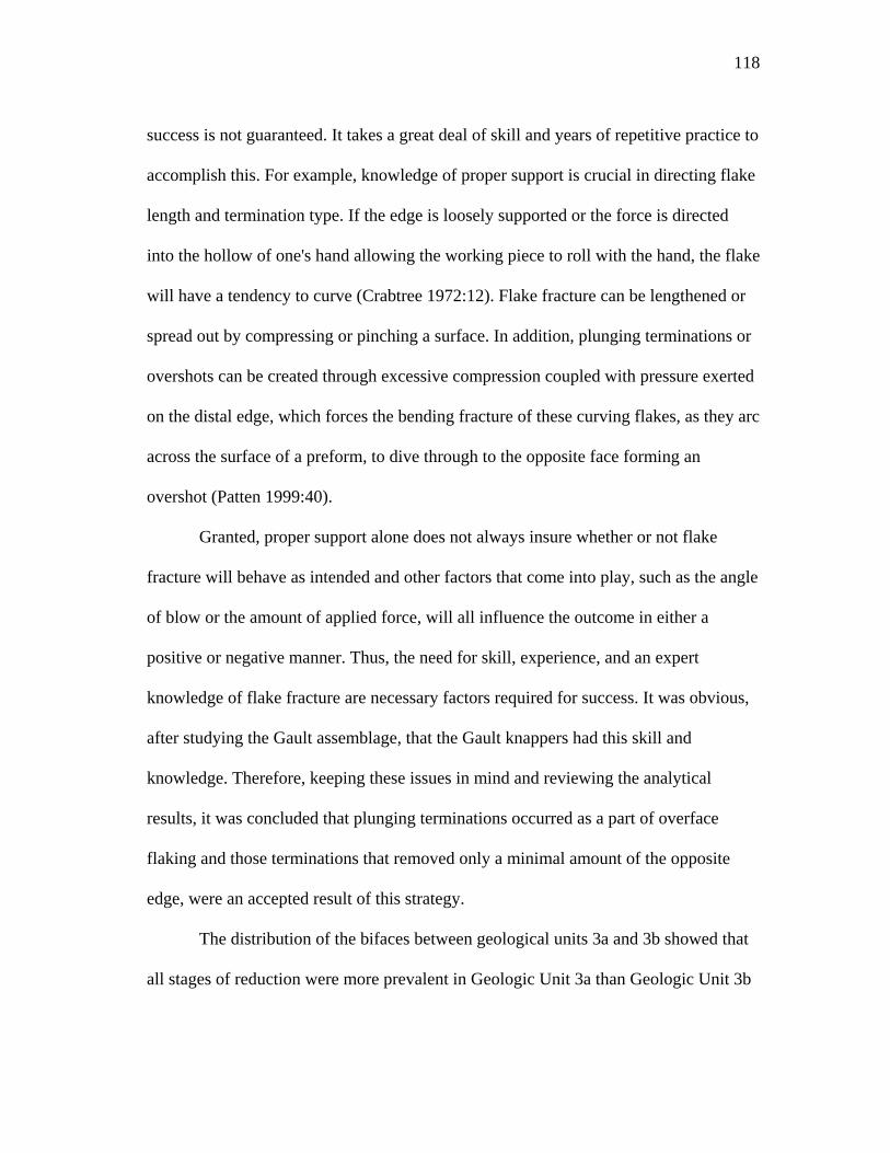
118
success is not guaranteed. It takes a great deal of skill and years of repetitive practice to
accomplish this. For example, knowledge of proper support is crucial in directing flake
length and termination type. If the edge is loosely supported or the force is directed
into the hollow of one's hand allowing the working piece to roll with the hand, the flake
will have a tendency to curve (Crabtree 1972:12). Flake fracture can be lengthened or
spread out by compressing or pinching a surface. In addition, plunging terminations or
overshots can be created through excessive compression coupled with pressure exerted
on the distal edge, which forces the bending fracture of these curving flakes, as they arc
across the surface of a preform, to dive through to the opposite face forming an
overshot (Patten 1999:40).
Granted, proper support alone does not always insure whether or not flake
fracture will behave as intended and other factors that come into play, such as the angle
of blow or the amount of applied force, will all influence the outcome in either a
positive or negative manner. Thus, the need for skill, experience, and an expert
knowledge of flake fracture are necessary factors required for success. It was obvious,
after studying the Gault assemblage, that the Gault knappers had this skill and
knowledge. Therefore, keeping these issues in mind and reviewing the analytical
results, it was concluded that plunging terminations occurred as a part of overface
flaking and those terminations that removed only a minimal amount of the opposite
edge, were an accepted result of this strategy.
The distribution of the bifaces between geological units 3a and 3b showed that
all stages of reduction were more prevalent in Geologic Unit 3a than Geologic Unit 3b
119
where the presence of late stages V, VI, and VII were reduced or lacking. The single
exception was a finished point found in Geologic Unit 3b. Although this implies a
possible lack of late stage reduction in Geologic Unit 3b, an overview of the full
overshot flakes suggests that late stage reduction also occurred in Geologic Unit 3b.
The numbers of secondary overshot flakes in Geologic Unit 3b exceeded those found
in Geologic Unit 3a, and the number of interior overshots from Geologic Unit 3b were
about one-half of the total number from Geologic Unit 3a. This suggests that middle
stage reduction, resulting in the final removal of cortex, was consistent within both
units. And, if one can accept that interior overshot flaking continued until the final
preform stage (fluting), it can then be inferred from their presence that late stage
reduction also occurred in Geologic Unit 3b. The lack of later stage bifaces in Geologic
Unit 3b can probably be attributed to sample size bias. The Gault site covers a very
large area and reduction debris, as noted in other excavations, was scattered and
recovered in varying numbers overall.
In conclusion, this study has showed that all stages of biface manufacture
occurred at Gault and that this reduction was performed in a rapid manner utilizing a
wide range of methods and techniques. Some of these techniques were modified for
different applications, such as the knowledge of making blades, which was adapted for
tab reduction in corner removals, end thinning, and final fluting. In addition, a variety
of methods were used in both platform preparation and fluting. This indicates that the
Gault knappers were not operating under a single strategy, but were aware of a number

120
of alternative ways of proceeding and made choices based upon individual or specific
needs or problems.
121
CHAPTER III
CLOVIS BLADE TECHNOLOGY
Blades, tools made on blades, and prepared blade cores have been reported
from a number of Clovis aged sites (Green 1963; Cox 1986; Fogelman 1986; Dragoo
1973; Redder 1985; Sanders 1990; Frison and Bradley 1991; Henderson and Goode
1991; Gramley 1993; Nami et al. 1975; Collins 1999) as well as from sites of probable
Clovis age (Soday 1954; Hammatt 1969; Long 1977; Hester, et al. 1992). The
abundance of sites containing blades indicates that a blade technology had been firmly
established by Clovis times. In fact, there is growing evidence for the existence of pre-
Clovis blade technologies such as Meadowcroft Rockshelter located in southwestern
Pennsylvania and Cactus Hill located on the Nottoway River in southeast Virginia. At
the Meadowcroft Rockshelter, a "small blade" industry was noted in sediments that
were dated between 11,300 and 16,000 years Before Present (B.P.) (Adovasio
2002:156-158), and blades were found eight inches below the established Clovis level
by Michael F. Johnson at Cactus Hill (as cited in the Mammoth Trumpet 1998
13(3):14-15).
The existence of a blade technology present within North America's earliest
tool assemblages should not be surprising as blades are among the World's oldest forms
of tools. Blades first appeared in the Middle Paleolithic of Central Asia approximately
250,000 years ago. Although pyramidal cores are present in these early assemblages,
the blades resemble elongated flake-blades more than true blades (Ranov and Schäfer
2000:80-82). More regular blade forms struck from prepared cores do not appear in
122
large numbers until the latter part of the Lower Paleolithic (Acheulian) and the Middle-
Paleolithic (Mousterian) transition of the Middle East (Rust 1950; Garrod 1970; Jelinek
1981:145-155; Bar-Yosef 1987:73; Ronen and Weinstein-Evron 2000:233) around
150-200 kyr B.P. (Copeland 2000:105). Blades continued in use during the Mousterian
(often in high frequencies) then almost disappear before being "re-invented" again
thousands of years later. This sequence of use, disappearance, and re-use continued and
spread, often appearing only as "local" industries, from the Mousterian until recent
times.
The continued re-invention of a blade technology should not be surprising as it
is the result of a basic knapping principle (i.e., striking flakes along a ridge) (Whittaker
1994:221). These ridges can be natural, the result of previous flake removals or from
purposely formed "crests" (Bordes and Crabtree 1969:4). Since fracture tends to follow
these "high" points, larger and longer flakes are more likely to be successfully
produced. With this principle in mind, some blades may actually be waste flake
debitage produced, not only from blade core production (Jelinek 1981:155), but also as
a result from the manufacture of other tool forms such as in biface preparation.
True blades vary little in width and thickness along their entire length, and (if a
simple dorsal ridge pattern is present) the sides are parallel or convergent (Movius et
al. 1968:4). They range in size from small microblades (Tixier 1963:35-39), less than 3
cm in length, to the larger, full sized macroblades such as those common to Clovis
assemblages (Collins 1999a) and Mesoamerica knapping sites (Shafer and Hester
1983). Blades were produced from prepared cores having a striking platform at one or
123
more ends, often with a crest formed on the longitudinal edge of the core that served as
a guiding ridge for the removal of the first blade. As each blade is detached, the
platforms are reformed by the removal of overhangs left by the negative bulbs of
previously struck blades (Newcomer 1975:99).
Reasons for continued use of blades include an efficient use of raw material
where little waste occurs during production (Sheets and Muto 1972:632-634) and the
presence of a very effective elongated cutting edge (Whittaker 1994:33), both desirable
factors in stone tool production. Blades are efficient tools used "as is" or broken into
segments for hafting, but they were also modified into other cutting, scraping, boring,
and in some cases, projectile points (Movius et al. 1968, Collins 1999a:10).
Previous Research
Clovis blade technology has not received much attention from prehistorians
other than noting the occasional occurrence of blades and blade cores occasionally
encountered within Clovis contexts (Collins 1999a:4). Collins' 1999 work (Clovis
Blade Technology) is the most comprehensive study on Clovis blades produced to date.
In his book, Collins presents a technological review of blade technology as well as
providing a comparative study of those blades and blade cores from known Clovis and
probable and non-Clovis contexts.
Collins (1999a:148) suggests that one reason for this lack of attention is that the
occurrence of blades is limited and that most examples of these are fragmented. In
some cases (such as at the Williamson site in Virginia) the presence of blades went
unnoticed or unreported (McCary 1951) but were later noted from subsequent
124
investigations (Cox 1986). In other cases (such as at the Graham Cave site in Missouri)
blades were simply misidentified as "flake knives" (Logan 1952). Collins (1999a:148)
lists only a few sites as having a "robust blade technology” such as the Stanfield-
Worely site in Alabama and the Wells Creek site in Tennessee. But for the majority of
sites reporting a blade or blade core presence, he describes the blades from these sites
as being "pieces that barely meet the definition of a blade, tend to be small, and often
occur in limited numbers.”
Another reason is that blades and blade cores are not widely distributed, nor do
they occur in large numbers on northeastern Paleoindian sites. Rather they appear to be
more prevalent on southeastern sites (Sanders 1990:67). Sanders reported true blades at
only two Clovis sites, the Adams site in Kentucky and the Wells Creek site in
Tennessee, but mentions several other southeastern Paleoindian sites such as the
Nuckolls and LeCroy sites in Tennessee and the Quad and Pine Tree sites in Alabama
as having a probable blade core industry (Sanders 1990:52-60,67).
This view is in basic agreement with Collins (1999a) where he noted small
numbers of "marginal" blades found on the majority of northeastern sites. However,
both fall short in concluding that a true blade core industry is absent in the northeast.
This may be due in part that most of the northeastern sites, often referred to as the
"Eastern Clovis" or represent an "Eastern Fluted Point Tradition," are dated to the end
of the Clovis period (i.e., around 11,000 radiocarbon years B. P.) (Taylor et al.
1996:517) or younger. This suggests that these sites may represent more of a
"transitional period" as opposed to the more "classic" Clovis period. Sanders, however,
125
restricted his research to eastern Clovis and Paleoindian sites and did not include any
western or southern Plains sites on which blades are fairly abundant (Stanford 1991:2).
In fact, the first site to describe a Clovis blade assemblage was a cache of 17 blades
recovered from Blackwater Draw, New Mexico (Green 1963). Since then, blades have
been found at other sites, such as Pavo Real in central Texas (Henderson and Goode
1991:26-28), Gault in Bell County Texas (Collins 1998:5-11), Murray Springs in
southern Arizona (Hemmings 1970: as cited in Collins 1999a:159), the Richey Clovis
Cache from East Wenatchee, Washington (Gramley 1993:45,50), Horn Shelter 2 in
central Texas (Redder 1985; Collins 1999a:160-161), and the Kevin Davis Cache in
Navarro County (Collins 1999a:75-153). In addition, Clovis "type" blades are found at
a number of sites containing either probable or indefinite Clovis contexts (Collins
1999a:162-165), some of which are Domebo in Oklahoma, Cedar Creek in western
Oklahoma (Hammett 1969:193-198), Anadarko in western Oklahoma (Hammatt
1970:145), McFaddin Beach on the upper Gulf Coast of Texas (Long 1977:10, 24),
Spring Lake in central Texas (Takac 1991:46-48), and Crockett Gardens in Willimson
County, Texas (McCormick 1982:12.135-12.166).
An interesting behavior among Clovis groups is the "caching" of artifacts
(Butler 1963; Green 1963; Lahren and Bonnichsen 1974; Gramley 1993; Stanford and
Jodry 1988; Young and Collins 1989; Frison and Bradley 1991; Mallouf 1994). These
caches usually consist of a variety of Clovis artifacts (i.e., projectile points, preforms,
fragments of ivory and other unusual materials such as quartz crystal and ocher)
(Stanford 1991; Collins 1999a). However, several caches (i.e., the Green [Green 1963]
126
and the Keven Davis [Young and Collins 1989; Collins 1999a] caches) are composed
only of blades. The Green Cache consists of 21 fragments that ultimately represented
17 blades (Green 1963:148), while the Kevin Davis Cache is composed of 27 blade
fragments that represent 14 blades (Collins 1999a9:93). In addition, a small number of
blade cores have also been reported found in possible caches (Goode and Mallouf
1991:67-70; Collins and Headrick 1992:26-39; Kelly 1992:29-33).
Caches are significant to the researcher as they can provide specific insights of
a group of similar tools produced and used at the same moment of time. Technological
attributes, for example, can be compared and quantified to produce a reliable picture
for that individual tool type which can be used within greater regional or temporal
studies. Collins (1999a) did this with the Kevin Davis Cache (and possibly with
additional specimens from Pavo Real) to create a description for Clovis blades from
which, he used to compare with blades from other sites and contexts.
Collins (1999a:84-92) used 13 measurements and indices in his analysis. These
include: maximum length, width, and thickness; platform angle; weight; platform
width; platform depth (thickness); index of curvature; width-to-length ratio; length +
width + thickness; length divided by length + width + thickness; width divided by
length + width + thickness; and thickness divided by length + width + thickness. In
addition, he recorded completeness, interior and exterior surfaces, platform type,
presence/absence of lipping, and type of fracture planes on the incomplete blades.
From these observations and calculations, Collins (1999a:63,178) defines
Clovis blades as having small platforms; with almost no bulbs, minimal ripple marks
127
on the interior surface giving a smooth aspect to the surface, and usually curved in
longitudinal section. They are generally long, often exceeding 100 mm, have narrow
and robust cross-sections, and relatively even and sharp lateral margins with a parallel
to sub-parallel dorsal flake scar pattern. The length-to-width ratios always exceed 3 to
1, commonly exceed 4 to 1, and occasionally exceed 5 to 1.
The initial definition of a blade according to Francois Bordes (1961) is "any
flake that is twice or more as long as it is wide.” This definition, however, was
believed to be too broad, and a more evolved definition was proposed by Don Crabtree.
Crabtree's (1972:42) definition states that a blade is "a specialized elongated flake with
parallel to sub-parallel edges, its length equal to at least twice its width. Cross or
transverse section may be plano-convex, triangular, subtriangular, rectangular, often
trapezoidal, and (on the dorsal face) one or more longitudinal crests or ridges. On the
dorsal side of the blade there should be two or more scars of previously removed
blades with force lines and compression rings indicating that force was applied in the
same direction as blade detachment.” Although more concise that Borde's earlier
definition, it is inclusive for all blades without any cultural or temporal distinctions.
Therefore, Collin's definition provides a much more definitive description for the
distinctive Clovis type blades.
Blade Manufacture
Raw Material
The first step in blade manufacture is the acquisition of suitable raw material.
Clovis blades (as well as other Clovis tools) are usually made of high quality materials
128
(Collins 1999a:178); thus, a reliable source would be required. Although a variety of
materials can be utilized (such as obsidian, jasper, agate, chalcedony, or some
quartzites) high quality chert or flint is one of the most common materials used. Cherts
and/or flints occur in a variety of forms that range from irregular to rounded nodules or
cobbles to flattened forms of ledge cherts. Ledge chert is often fractured from
overburden pressures while in the parent limestone matrix and, as they weather out,
break into thick blocky chunks. Not all ledge chert was subjected to overburden
fracturing, and these erode out as thinner plate-like tabs that can occur in sizes up to
several feet across.
Initial Core Preparation
For blade production to be successful material shape is critical. Since fracture
tends to follow ridges (Whittaker 1994:220-221), materials with one or more natural
ridges,such as rectangular blocky forms were desirable (Bordes and Crabtree 1969:3;
Whittaker 1994:221; Patten 1999:56). For those materials without ridges, or if existing
ridges are irregular, the surface is prepared by removing small flakes from the edge,
either unifacially or bifacially, that straightened or created a ridge. The edge thus
formed is called a crest, and the blade removed is called a crested blade or lamé à crête
(Bordes and Crabtree 1969:4,15; Crabtree 1972:72; Collins 1999a:19). A suitable ridge
can also be made on material without having angular edges by the removal of one end
forming a striking platform from which blades can then be struck off from one or more
sides (Bordes and Crabtree 1969:3-4; Whittaker 1994:221). Once the first blade has
129
been removed, two or more guiding ridges are created (Patten 1999:56) which sets up
the surface for subsequent removals.
Platforms
Before any blade could be removed, a good platform must be established on the
core. A platform can be natural; that is, needing no preparation or it may require some
form of preparation. As indicated above, to establish a platform where no suitable
natural platform exists, one of the ends of a tab or cobble will have to be removed. This
can be accomplished by striking the end against an anvil stone or by direct hard
hammer percussion. Once the end has been removed, portions of the surface may
contain a satisfactory angle that require only minimal isolation or surface grinding to
form a desired platform. If the angle at the point of blade detachment is unsatisfactory,
additional trimming and facetting may be necessary (Whittaker 1994:224). The desired
exterior platform angles should be acute, but the closer the angle is to 90Ε the longer
the blade will be (Whittaker 1994:223; Collins 1999a:22).
Both of these methods, however, often result in step or hinge fractures. To
avoid these terminations, Bordes and Crabtree (1969:5) describe another method to
form a promitory that will become the striking platform. The first step is to isolate the
area where the promitory is to be formed. This is accomplished by pressing and
thrusting a hammerstone downward and outward along the core's edge adjacent to the
area to be isolated. This action is continued until the isolated area forms a promitory
whose center is above the ridge and in line with the axis of the future blade. The result
is a small, isolated, and strong platform is formed as well as removing any previous
130
overhangs. To add strength, the top of the platform can be abraded by rubbing it with a
granular stone.
An additional problem often results on the tops of conical cores. As platforms
were formed around the periphery of the core, such as conical or polyhedral cores,
some flakes terminated in step or hinge fractures and combined with angles created by
the deep negative bulb scars that resulted from platform isolating, a central hump or
knot is often formed (Collins 1999a:51). The resulting angles and stacking around the
edges of this knot made it difficult for re-platforming. Therefore, the entire top of the
core was removed in order to create a surface suitable to reform new platforms.
Blade Removal
Once a platform has been formed, a blade can be struck off. Removals were
accomplished by direct percussion with either a hard hammer or soft hammer, indirect
percussion using a punch (Bordes and Crabtree 1969:6; Whittaker 1994:221; Collins
1999a:13-15), or by pressure (Crabtree 1972:14; Clark 1987: 266-268; Whittaker
1994:221). Since blades are fragile and easily broken, a strong platform, good platform
angle, proper applied amount of force, precision, and support are all considerations that
must be met for success.
Direct percussion is the least precise method of the techniques available
(Whittaker 1994:221,223). Blows, whether with a hard hammer or soft hammer, can be
easily mis-directed, striking either to one side or too deep into the core. Although hard
hammer percussion can successfully produce blades (Moore 2003:41), its use is not
considered the best way to produce long blades as it produces too great a stress and
131
shock, a problem that results in frequent breakage (Whittaker 1994:223; Patten
1999:57). In addition, hard hammer removals produce large bulbs and strong waves on
the flake or blade's ventral surface, a trait Collins (1999a:30-31, 63) stresses are not
generally found on Clovis blades.
Through experimental replication, Collins found that a soft hammer billet could
produce many of the traits seen on Clovis blades. For this study, Collins enlisted the
help of Glenn T. Goode, an archaeologist and expert flintknapper from Austin, Texas.
Over a period of six years Goode produced a few thousand blades and a few hundred
blade cores. Goode concluded from these replications that soft hammer percussion
combined with the proper support could reproduce identifiable Clovis blade traits
(Collins 1999a:27-32).
Indirect percussion utilizing a punch is a widely used and successful method for
blade removal, especially on brittle materials such as obsidian (Bordes and Crabtree
1969). The primary reason for this is that a punch can be set directly on the platform,
which allows for the very precise placement of the force and control of the angle of
force (Whittaker 1994:221). As a result of Goode's replications and his study of known
Clovis blade cores, Collins (1999a:63-66) suggests that both direct soft hammer and
indirect (punch) percussion were both used in Clovis blade production with the indirect
method being the more common. However, it has been determined that blade attributes
cannot be used to definitely distinguish between direct soft hammer percussion and
indirect-percussion (Newcomer 1975:100; Whittaker 1994:224).
132
Pressure flaking can be used to produce blades (Crabtree 1972:14). Because
blades are larger than normal pressure flakes, they require the use of a specialized
pressure tool (Whittaker 1994:221). Such a tool was successfully used by Crabtree in
replicating Mesoamerican blades utilizing a chest crutch (Crabtree 1968), and J. B.
Solberger who developed a "lever assisted fluting jig" to flute Clovis, Folsom, and
Cumberland points (Solberger 1978:6-7). In reference to Clovis blade manufacture,
however, there is no indication that a pressure technique was applied (Collins 1999a).
Support
It is generally believed that proper support is a key element in successfully
producing blades (Bordes and Crabtree 1969:8-10; Whittaker 1994:225; Collins
1999:30). Experimentally, various methods have been employed. Francois Bordes, for
example, favored holding the core between his feet, while Jacques Tixier preferred to
pin a core down under one foot and strike blades off sideways (Whittaker 1994:225).
Crabtree found that by holding a core between his knees the core was allowed
to freely move when struck with a punch. This resulted in blades that were strongly
curved. He also was able to punch curved blades from uni-directional cores without a
rest by simply placing the core on the ground. When he immobilized a core by
supporting it on a hard surface, the resulting blades were flat or gently curved. Upon
examining a large conical core from Comanche County, Texas (Green 1963:161),
Crabtree found many of the flake scars to be flat, not curved, and by all indications,
they had been flaked with a punch. This led him to conclude that, occasionally, curved
133
blades could be produced with a hard rest, but that straight blades could also occur with
a soft rest or none at all (Bordes and Crabtree 1969:9-10).
In Goode's experiments, blades struck from cores supported on a firm base also
resulted in greater blade breakage with less refined attributes (i.e., larger bulbs and
more rippled interior surfaces). Like Crabtree, Goode found that it was necessary to
allow the core to move slightly upon impact. He also found that, up to a point, the less
firmly a core is supported the smoother the ventral surface, but if held too loosely the
core can recoil under impact, dissipating the force and ruining the core (Collins
1999a:30).
Core Maintenance
Clovis blades were produced from two types of cores, conical and wedge-
shaped. Conical cores are described as having the general plane of the platform at right
angles to the long axis of the core and to the proximal blade facets. A blade facet is
formed as each blade is removed and as additional blades are removed. These facets
form a convex face, sometimes around the circumference of the core. The result is that
the distal ends of these cores begin to converge to a point (Collins 1999:50-59). The
platform plane is composed of multiple, short, deep flake scars that emanate from its
periphery. The negative bulb scars from each of these flakes form an acute angle of
approximately 60° to 70° with the core face. These flake scars are the result of platform
maintenance flakes and, as they are removed around the periphery of the core's surface,
they often terminate in hinges eventually forming the large central knot. When this
134
occurred the entire top of the core needed to be removed in order to reform new
platforms. The removed portion or tops of the cores are called core-tablets.
Wedge-shaped cores differ from conical cores by having a different overall
shape, being made on thinner or flattened chert tabs, as apposed to the more chunky
cherts selected for conical cores. These cores have an acute angle between the platform
and the core face, a narrow core face with multifaceted platforms. Platform
maintenance flakes are simpler than those of the conical type, consisting of trimming
an acute bifacial edge. In addition, a single core face may contain two opposing
platforms with blades detached from these being less curved in longitudinal section
(Collins 1999a:51).
Problems begin immediately as blade removals progress. The knots formed
from platform maintenance flaking on conical cores often becomes so prominent that,
during direct percussion, it prevents further blade removals by interfering with the
arching swing of the billet. To correct this problem, the platform surface was
rejuvenated by the removal of the entire surface and such flakes removed are known as
core-tablet flakes (Collins 1999a:51, 58). Collins (1999a:59) noted that negative bulb
scars on core faces and on the exterior of blades were infrequent, suggesting that core-
tablet removals occurred at frequent intervals.
As each blade is removed, the ridges formed become the guides for additional
blade removals. Unsuccessful blade detachments, in the form of hinge and step
terminations or from material flaws, were frequent. To correct these problems, flakes
were removed from the lateral edges (Collins 1999a: 8) and/or the distal end (Collins
135
1999a:58). The narrower nature of the flaked surface on the wedge-shaped cores was
more easily corrected than those on conical cores. Hinge and step terminations were
also removed by alternating the ends. However, the wider and multi-faceted nature of
the conical cores offers special problems. On these cores hinge and step terminations
could also be removed by flaking from the core's distal end, but in some cases,
corrective flakes were laterally flaked from ridges flaked adjacent to the failed blade
attempt or from ridges next to unflaked surfaces. Collins (1999a:54) noted that some
flaking from these ridges was also performed to correct irregularities resulting from
misdirected blade removals.
Blade Types
During Clovis blade manufacture, a variety of blade-like flakes and blades are
produced, beginning with initial core preparation and continuing throughout the
reduction process of the cores. This is particularly evident on lithic manufacture sites
containing large amounts of debitage. Many of these flakes conform to the basic
definition of a blade (i.e., twice as wide as they are long) but fall short of being a
regular "classic" blade, usually thought of as the intended end product. Collins
(1999a:90-92) addressed this problem by categorizing the blades into six stages. He
stresses, however, that these stages are somewhat subjective and not absolutely
sequential, but were designed as a generalization of where the blades fit in the
sequence of removals in an idealized blade-core reduction.
Collins's (1999a:90-91) blade stages are as follows:
136
1. Primary blades with natural exterior surfaces; natural exteriors are cortex or
partially cortex; lateral edges are regular; both bulb and platforms are often
large suggesting hard hammer, direct percussion, longitudinal sections are
straight to slightly convex.
2. Secondary cortex blades with prepared crests and possibly one or two scars
of prior blade removals, usually multiple flake scars of varying orientations,
edges are irregular, usually with flake scars; slight longitudinal curvature in
most specimens, but moderate curvature in a few; large bulbs, possibly
produced by hard hammer percussion.
3. More regular blades with minor cortex or crest remnants; usually one or
two, sometimes more, prior blade scars on the exterior; core preparation
flake scars present on the exterior; edges regular; flat bulbs and large bulbs
both occur; variable, but generally relatively little, longitudinal curvature.
4. Moderately regular blades, little or no cortex, multiple prior scars and some
core-preparation flake scars, flat bulbs, moderate curvature.
5. Regular blades, no cortex, multiple prior blade scars, flat bulbs, strong
curvature.
6. Very regular blades, no cortex, multiple prior blade scars, flat bulbs, strong
curvature; some scars of prior blades removed from distal end of core (some
relatively narrow blades are seen in this stage).
Another flake form that resembles a blade is the blade-like flake. These flakes
are large (twice as long as they are wide) are relatively straight, and have one or more
137
dorsal ridges. It is felt that flakes of this type were detached from large cores by direct
percussion and possess a mix of flake and blade characteristics (Collins 1999a:32).
Gault Blade Analysis
Analytical Procedures
In all, 464 blades (all types), 50 blade cores, and 36 core tablets were recovered.
In addition, 3 blades, 4 blade-flakes and 1 core were refitted into three separate co-
joined pieces. Two hundred and ninety-seven blades were thoroughly analyzed, and the
remaining 167 were too fragmented for a complete analysis but were examined for any
specific individual attributes that remain. Unless otherwise noted, all specimens
utilized in this study were recovered from the Clovis soil (Geologic Unit 3a) or Clovis
clay (Geologic Unit 3b) (Figure 2). At times, during excavation, geologic units 3a and
3b were indistinguishable from each other; therefore, artifacts from these situations are
placed in a Geologic Unit 3a or Geologic Unit 3b category. The majority of the blades
(N = 275) were found within the Clovis clay Geologic Unit 3a, 131 were found in the
Clovis soil Geologic Unit 3b, and 48 were found in geologic units 3a or 3b (Appendix
A, Table 1).
A number of attributes were coded. These include blade type, maximum length,
width, thickness, condition, platform type, platform angle, platform width, platform
thickness, type of platform preparation, dorsal scar pattern, blade profile, termination
type, and edge angles. In addition, each blade was illustrated noting any modifications,
the ventral or interior surface attributes, such as presence or absence of platform
lipping, size of the bulb of percussion, and the degree of ventral surface smoothness.
138
Analyzing began by initially dividing the blades into the three primary flake
types, for example primary, secondary, and interior flakes (Figure 23). Primary blades
are those blades that are 90% or more covered in cortex, secondary blades are those
having less than 90% cortex, and interior blades are those having no cortex. Blades
within each of these categories were then sub-divided into groups based on individual
blade attributes (i.e., regular and irregular forms). Regular blades are those blades
having uniformly straight sides, and irregular, or those blades whose sides undulate,
have portions of an edge that protrude or are jagged. More specialized blade types
such as crested blades, corner/side removal blades, end thinning blades, and core
maintenance blade\blade-flakes were each analyzed separately.
Platforms are an essential aspect in understanding how lithic tools were made
(Figure 24). The manufacture and control of platforms are critical factors for successful
flaking and the types of platforms are good indicators as how, and in some cases, when
this was accomplished. For example, initial flaking usually commenced on an
unprepared or natural surface or one that has had minimal preparation, such as a single
flake removal or plain surface. As reduction continues, more carefully prepared
platforms are required for specific flake removals to be successful as well as preventing
material failure. Platforms are usually made by careful pressure or light percussion
flaking of a core or blank's edge. In addition, isolating (flaking adjacent to the
platform) and the grinding or abrading platform surface are used in guiding flake
fracture and the strengthening of the platform itself. The types of platforms include
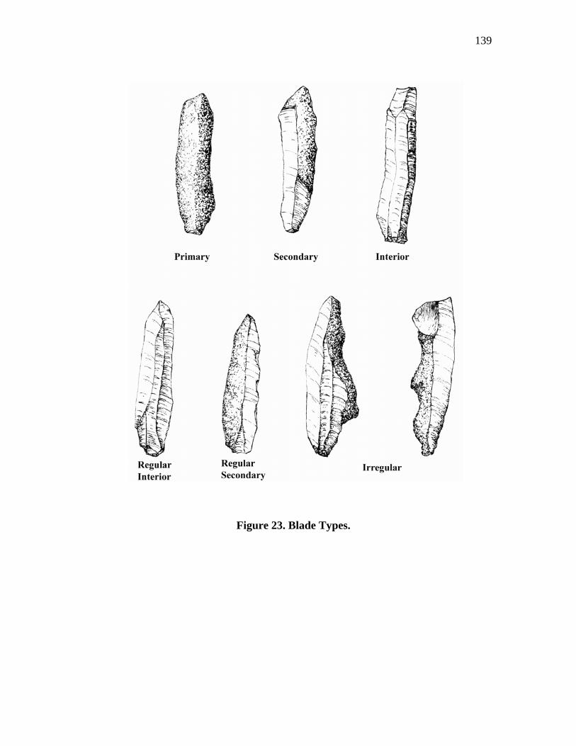
139
Figure 23. Blade Types.
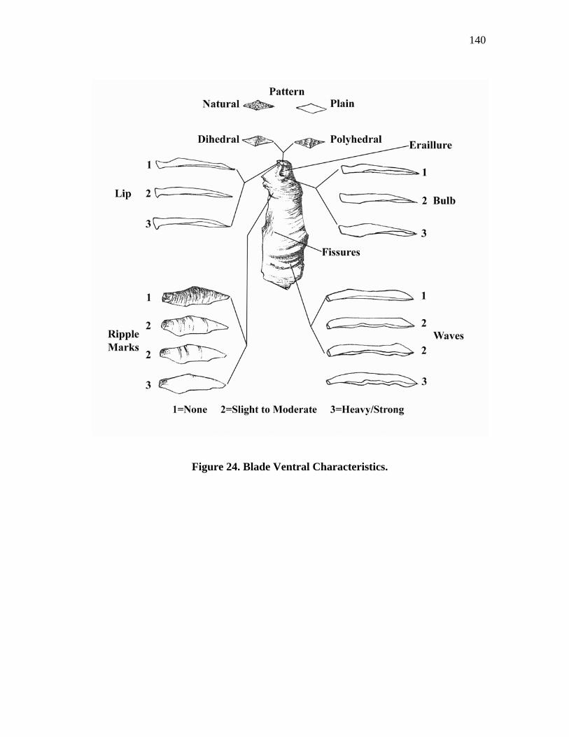
140
Figure 24. Blade Ventral Characteristics.
141
(1) natural, or those completely covered in cortex, (2) plain, or those without cortex or
facets (small flakes removed from the surface), (3) dihedral are those with two facets,
and (4) polyhedral are those having three or more facets, that are and crushed or
broken.
Bulbs of percussion are often considered as indicators for the type of percussor
or hammer used in manufacture. Briefly, a bulb of percussion (Figure 24) is a swelling
located in front of the platform (Crabtree 1972:48; Whittaker 1994:14) and is usually
considered as evidence for hard-hammer percussion (Whittaker 1994:185). On some
flakes, the ventral surfaces are flat or diffuse with no swelling. In these cases, this is
considered as an indicator for the use of a soft-hammer or one made of a soft material
such as antler or wood. The bulbs recorded in this analysis were categorized as (1)
diffuse (none), (2) slight to moderate swelling, and (3) strongly present.
Platform lipping is another indicator for the type of percussor used and often
considered in conjunction with type of bulb. Lips are small projections or overhangs
found on the proximal ventral surfaces of some flakes (Figure 24) and are thought to be
a trait for soft-hammer or pressure flaking (Crabtree 1972:74; Whittaker 1994:187).
Platform lipping in this analysis was recorded as either (1) absent, or (2) slight to
strongly evident.
Because the presence of ripples and/or waves on the ventral surfaces of flakes
and blades is thought to indicate the type of percussor utilized, their presence or
absence was noted. Ripples (Figure 24) are small concentric lines that often emanate
from the center of the bulb of percussion on fine grained materials and are directly
142
related to the force of blow and the crack that results as it moves through a piece of
material (Whittaker 1994:14). These ripples or compression rings are thought to be
created by the back and forth shifting in the knapping force, while the amplitude and
frequency of these rings are seen as a rough measure of the energy available during
each stage of flake fracture (Patten 1999:52). Because soft hammers distribute energy
more evenly than hard hammers, some feel that an absence of ripples on the ventral
surface of a flake or blade indicates the use of a soft hammer or punch (Collins
1999a:66).
Some control of the force and direction of fracture influencing the creation of
ripples can be manipulated through support of the core. For example, Glenn Goode, in
his experimental replication of Clovis blades, found that, up to a point, the less firmly
he supported a core, the smoother the surface and smaller the bulb will be. However,
resting a core on the ground or on a piece of wood caused larger bulbs and a more
rippled interior surface (Collins 1999a:30).
Waves (Figure 24) are larger, less frequent undulations created by the fracture
front shifting inward and outward as fracture develops. These are often created by a
mechanical imbalance such as damage to a platform or tool, poor control, or type of
tools utilized. For example, hesitations in the development of a fracture cause the
trajectory of this fracture to waver due to the relaxation of compression allowing the
fracture to veer toward the free surface. The greater the force the larger the undulation.
The use of hard hammers are more likely to cause undulations as soft hammers tend to
transform energy slowly and evenly enough for fracture to be more stable, thus
143
reducing their formation (Patten 1999:52,82,86,108). Ripples and waves were recorded
in this analysis as (1) none, (2) slight to moderate, and (3) heavy or strong. The blades
were also categorized by shape and profile (Figure 25). Cross-sections (view taken
from proximal end) include (1) flat (plano) with no dorsal curvature, (2) rounded
(convex) with dorsal curvature, (3) triangular, and (4) polyhedral, or those with
multiple vectors. The edges range from acute to steeply angled or abrupt. Blade
profiles (side view) recorded include (1) flat with no curvature, (2) twisted, (3)
proximal bend, (4) medial bend, or (5) distal bend.
The dorsal surfaces of the blades were categorized as (1) uni-directional (those
surfaces with one or more flake scars flaked in the same direction), (2) bi-directional
(those with flake scars originating from two directions - may be proximal-ventral or
from the lateral), and (3) radial (those having flake scars originating from all sides)
(Figure 26). In addition, combinations of these directions, such as uni-directional from
lateral, uni-directional from distal or proximal, bi-directional from proximal or distal
and lateral, etc. were individually recorded.
The termination types (Figure 27) were also recorded as (1) straight or blunt
(those terminations that are "square" such as from step fractures or fracturing on a
straight edge), (2) overshot or plunging (those that fractured over an edge), (3)
feathered (those that fractured into a thin sharp edge), (4) hinged (those that terminate
in a rounded or blunt edge), and (5) broken. In addition, the distal ends of blades were
noted as (1) expanding, (2) converging, (3) rectangular, (4) bend to one side or the
other (de bordant), or (5) asymmetrical.
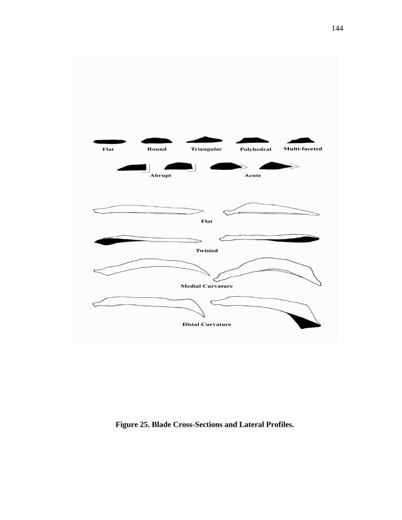
144
Figure 25. Blade Cross-Sections and Lateral Profiles.
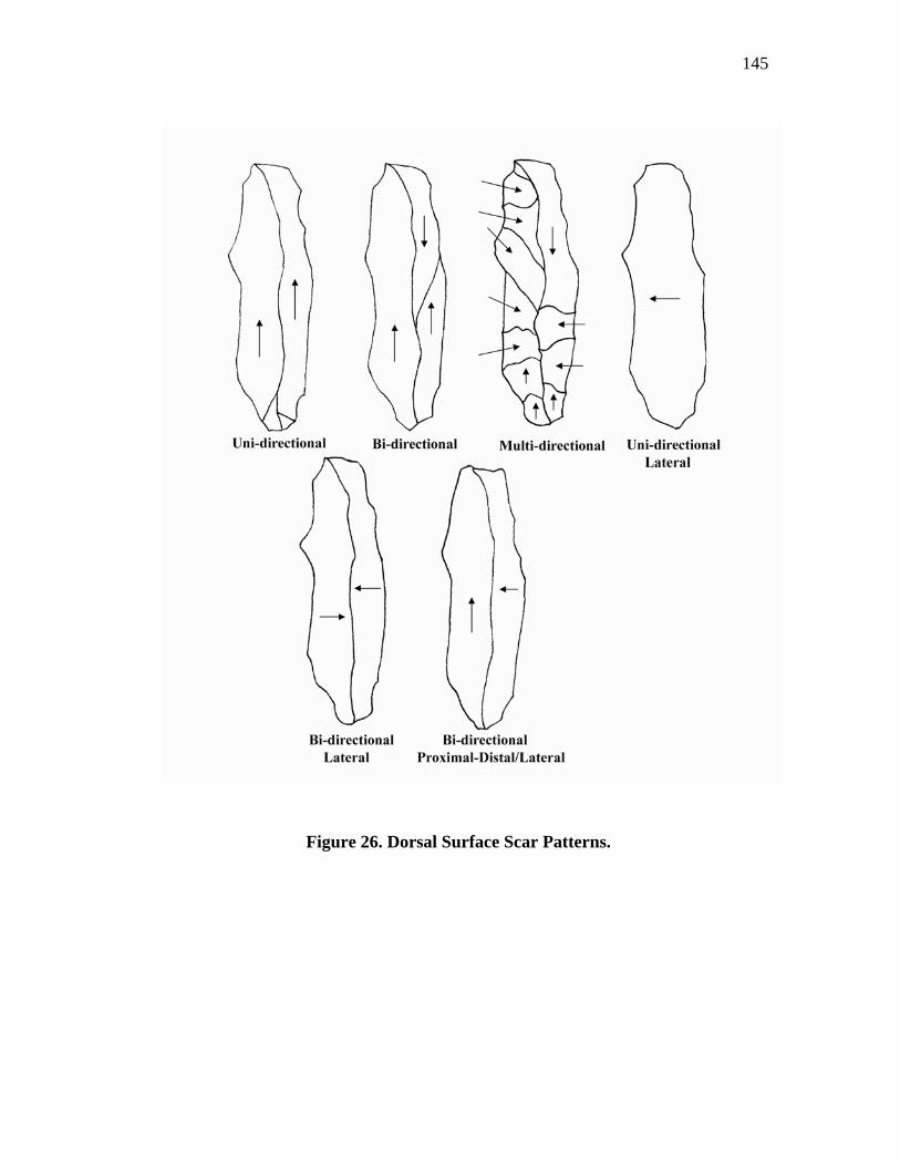
145
Figure 26. Dorsal Surface Scar Patterns.
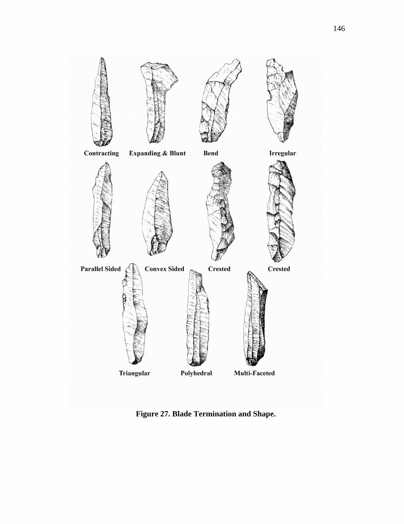
146
Figure 27. Blade Termination and Shape.
147
A number of calculations were computed for measurements taken on the length,
width, and thicknesses for each blade. In most cases, these measurements were taken
only on those blades that were complete or contained an observable specific attribute.
These measurements include the following:
1. Length and width averages.
2. Index of curvature (Figure 28). This is a ratio of two linear
measurements taken on the interior surface of the blade. These
measurements are (1) the straight line (length between the proximal and
distal ends) and (2) a perpendicular measurement between the
perpendicular plane and the interior surface of the blade. This is a
generalized expression of curvature where the greater the value of index
the more curved the blade (Collins 1999a:86-87; Figure 5.3).
3. Width to length ratios. This is an arithmetic expression of the maximum
length in relation to maximum width, with width given an arbitrary
expression of one (Collins 1999a:86).
4. Length + width + thickness. This is the sum of the measurements of the
maxim length, maximum width, and maximum thickness. It is simply a
generalized value of size and is used in the calculations of the three
following ratios (Collins 1999a:86).
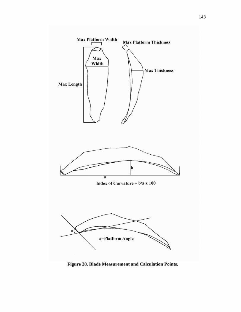
148
Figure 28. Blade Measurement and Calculation Points.
149
5. Length divided by length + width + thickness ratios. This is a ratio of
length to the sum of the primary dimensions used to provide a graphic
presentation of shape (Collins 1999a:86).
6. Width divided by length + width + thickness ratios. This is a ratio of the
width to the sum of the primary dimensions used to provide a graphic
presentation of Collins (1999a:86).
7. Thickness divided by length + width + thickness ratios. This is a ratio of
the thickness to the sum of the primary dimensions used to provide a
graphic presentation of shape (Collins 1999a:86). Clovis blade
manufacture is a process of constant platform rejuvenation and core
maintenance procedures that re-occur after each blade removal and
continued until the core was exhausted. Blades produced from conical
cores were detached around the periphery of a core made from rounded
cobbles or thick blocky cherts. Once the initial core preparation was
accomplished and the first series of blades were removed, all subsequent
blades produced are interior with no cortex.
However, blades made from wedge-shaped cores were continually removed
from the narrow (end) face of thinner chert tabs. The repetitive removal of blades from
the ends of this core type includes not only interior types but also numbers of
secondary types removed from each of the core edges as well. With wedge-shaped
cores being the more abundant type, the result would be a significant increase in the
150
number of secondary blades. The secondary blades may be as regular and desirable as
the interior blades with the only difference being the presence of some cortex. Using
Collins' model, these secondary blades would be placed variously within his stages 4, 5
or 6. The result of this could result in a skewing effect in their analysis. Therefore,
based on the core differences, it was felt that a better understanding of the Gault blades
would be derived from a more traditional method of core reduction sequences.
Blade Analysis
The following is a discussion of the individual blade types analyzed for this
study.
Primary Blades (N = 37, Figure )
Primary blades are those blades removed during the initial preparation of the
core for blade manufacture. The surfaces are 90%-100% covered in cortex and/or a
white patina. White patina has commonly been thought to be produced when silica was
replaced by lime salts; however, it is currently thought to have formed when silica is
removed from the surface of cherts buried in alkaline environments, such as soil
(Luedtke 1992:109) or standing water (Purdy 1981:127).
The patina noted on the chert from Gault ranges from a bluish-white film to a
heavy, almost thickened grayish-white covering that has formed over the fractured
surfaces of the chert nodules. Most of these fractured surfaces were created from
overburden pressures exerted on the chert bearing beds while in their parent limestone
matrix. As the chert eroded from the limestone matrix, it broke into variously sized
blocky chunks where over time this patina formed over the exposed fractured surfaces.
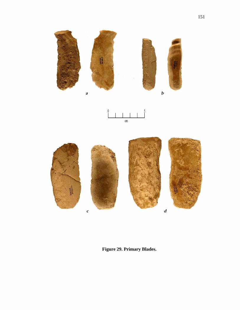
151
Figure 29. Primary Blades.
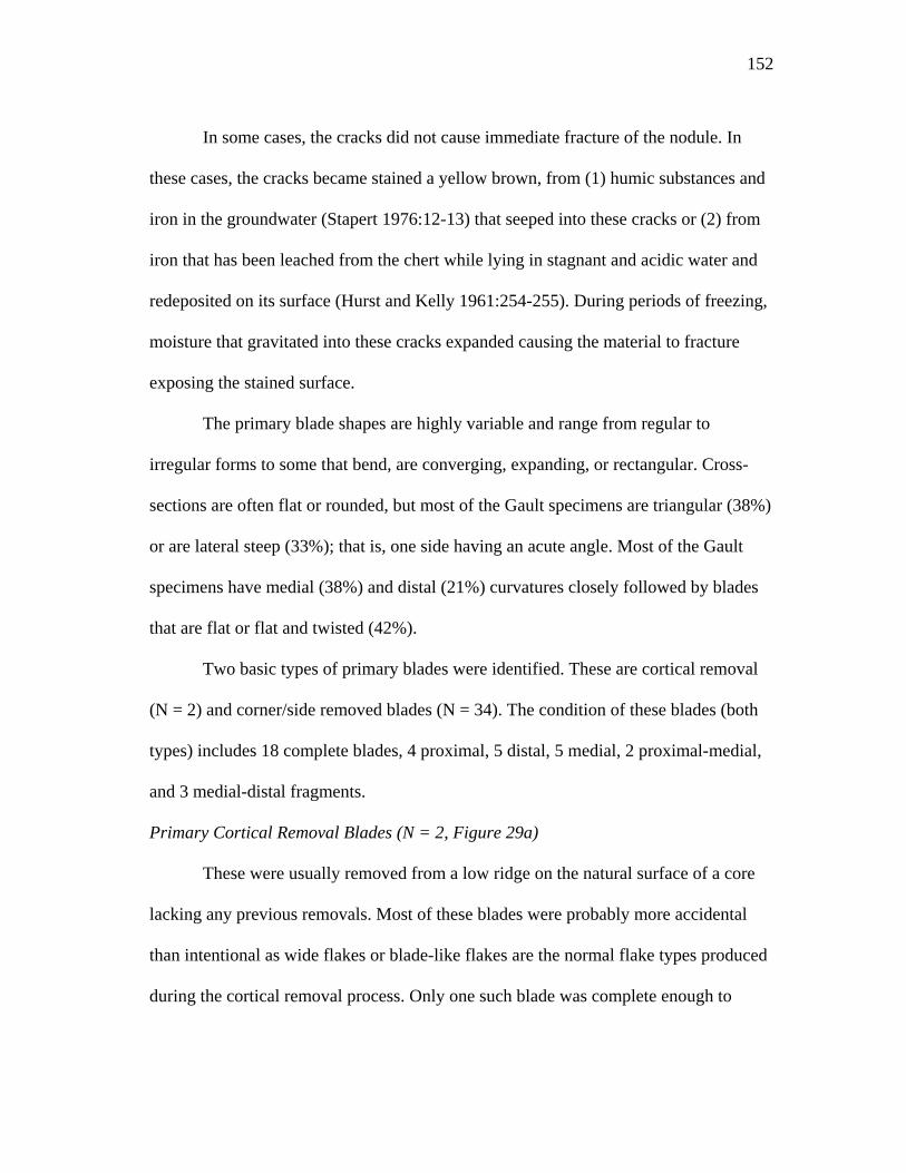
152
In some cases, the cracks did not cause immediate fracture of the nodule. In
these cases, the cracks became stained a yellow brown, from (1) humic substances and
iron in the groundwater (Stapert 1976:12-13) that seeped into these cracks or (2) from
iron that has been leached from the chert while lying in stagnant and acidic water and
redeposited on its surface (Hurst and Kelly 1961:254-255). During periods of freezing,
moisture that gravitated into these cracks expanded causing the material to fracture
exposing the stained surface.
The primary blade shapes are highly variable and range from regular to
irregular forms to some that bend, are converging, expanding, or rectangular. Cross-
sections are often flat or rounded, but most of the Gault specimens are triangular (38%)
or are lateral steep (33%); that is, one side having an acute angle. Most of the Gault
specimens have medial (38%) and distal (21%) curvatures closely followed by blades
that are flat or flat and twisted (42%).
Two basic types of primary blades were identified. These are cortical removal
(N = 2) and corner/side removed blades (N = 34). The condition of these blades (both
types) includes 18 complete blades, 4 proximal, 5 distal, 5 medial, 2 proximal-medial,
and 3 medial-distal fragments.
Primary Cortical Removal Blades (N = 2, Figure 29a)
These were usually removed from a low ridge on the natural surface of a core
lacking any previous removals. Most of these blades were probably more accidental
than intentional as wide flakes or blade-like flakes are the normal flake types produced
during the cortical removal process. Only one such blade was complete enough to
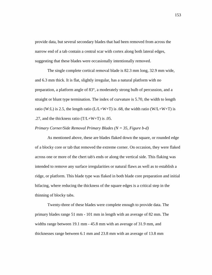
153
provide data, but several secondary blades that had been removed from across the
narrow end of a tab contain a central scar with cortex along both lateral edges,
suggesting that these blades were occasionally intentionally removed.
The single complete cortical removal blade is 82.3 mm long, 32.9 mm wide,
and 6.3 mm thick. It is flat, slightly irregular, has a natural platform with no
preparation, a platform angle of 83°, a moderately strong bulb of percussion, and a
straight or blunt type termination. The index of curvature is 5.70, the width to length
ratio (W:L) is 2.5, the length ratio (L/L+W+T) is .68, the width ratio (W/L+W+T) is
.27, and the thickness ratio (T/L+W+T) is .05.
Primary Corner/Side Removal Primary Blades (N = 35, Figure b-d)
As mentioned above, these are blades flaked down the square, or rounded edge
of a blocky core or tab that removed the extreme corner. On occasion, they were flaked
across one or more of the chert tab's ends or along the vertical side. This flaking was
intended to remove any surface irregularities or natural flaws as well as to establish a
ridge, or platform. This blade type was flaked in both blade core preparation and initial
bifacing, where reducing the thickness of the square edges is a critical step in the
thinning of blocky tabs.
Twenty-three of these blades were complete enough to provide data. The
primary blades range 51 mm - 101 mm in length with an average of 82 mm. The
widths range between 19.1 mm - 45.8 mm with an average of 31.9 mm, and
thicknesses range between 6.1 mm and 23.8 mm with an average of 13.8 mm
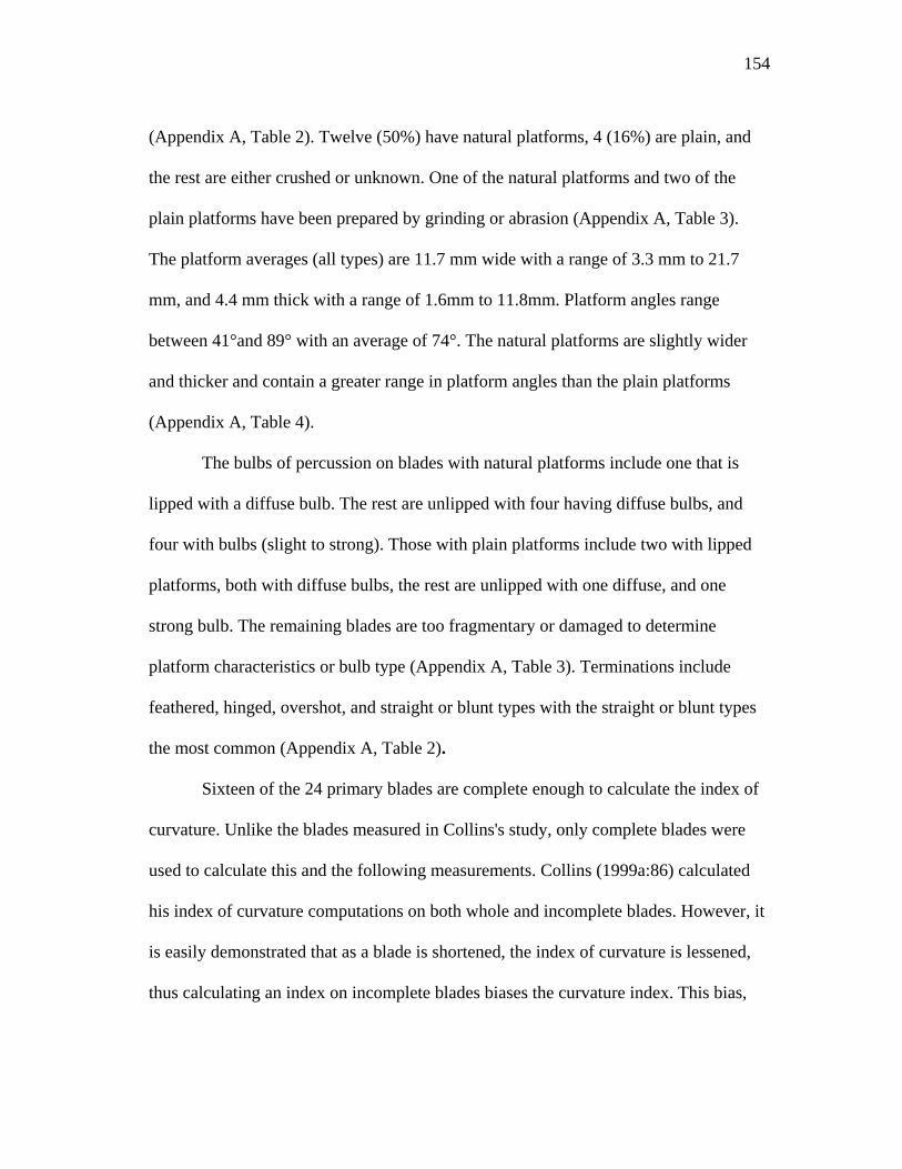
154
(Appendix A, Table 2). Twelve (50%) have natural platforms, 4 (16%) are plain, and
the rest are either crushed or unknown. One of the natural platforms and two of the
plain platforms have been prepared by grinding or abrasion (Appendix A, Table 3).
The platform averages (all types) are 11.7 mm wide with a range of 3.3 mm to 21.7
mm, and 4.4 mm thick with a range of 1.6mm to 11.8mm. Platform angles range
between 41°and 89° with an average of 74°. The natural platforms are slightly wider
and thicker and contain a greater range in platform angles than the plain platforms
(Appendix A, Table 4).
The bulbs of percussion on blades with natural platforms include one that is
lipped with a diffuse bulb. The rest are unlipped with four having diffuse bulbs, and
four with bulbs (slight to strong). Those with plain platforms include two with lipped
platforms, both with diffuse bulbs, the rest are unlipped with one diffuse, and one
strong bulb. The remaining blades are too fragmentary or damaged to determine
platform characteristics or bulb type (Appendix A, Table 3). Terminations include
feathered, hinged, overshot, and straight or blunt types with the straight or blunt types
the most common (Appendix A, Table 2).
Sixteen of the 24 primary blades are complete enough to calculate the index of
curvature. Unlike the blades measured in Collins's study, only complete blades were
used to calculate this and the following measurements. Collins (1999a:86) calculated
his index of curvature computations on both whole and incomplete blades. However, it
is easily demonstrated that as a blade is shortened, the index of curvature is lessened,
thus calculating an index on incomplete blades biases the curvature index. This bias,
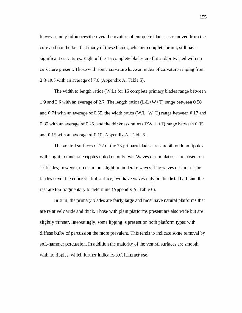
155
however, only influences the overall curvature of complete blades as removed from the
core and not the fact that many of these blades, whether complete or not, still have
significant curvatures. Eight of the 16 complete blades are flat and/or twisted with no
curvature present. Those with some curvature have an index of curvature ranging from
2.8-10.5 with an average of 7.0 (Appendix A, Table 5).
The width to length ratios (W:L) for 16 complete primary blades range between
1.9 and 3.6 with an average of 2.7. The length ratios (L/L+W+T) range between 0.58
and 0.74 with an average of 0.65, the width ratios (W/L+W+T) range between 0.17 and
0.30 with an average of 0.25, and the thickness ratios (T/W+L+T) range between 0.05
and 0.15 with an average of 0.10 (Appendix A, Table 5).
The ventral surfaces of 22 of the 23 primary blades are smooth with no ripples
with slight to moderate ripples noted on only two. Waves or undulations are absent on
12 blades; however, nine contain slight to moderate waves. The waves on four of the
blades cover the entire ventral surface, two have waves only on the distal half, and the
rest are too fragmentary to determine (Appendix A, Table 6).
In sum, the primary blades are fairly large and most have natural platforms that
are relatively wide and thick. Those with plain platforms present are also wide but are
slightly thinner. Interestingly, some lipping is present on both platform types with
diffuse bulbs of percussion the more prevalent. This tends to indicate some removal by
soft-hammer percussion. In addition the majority of the ventral surfaces are smooth
with no ripples, which further indicates soft hammer use.
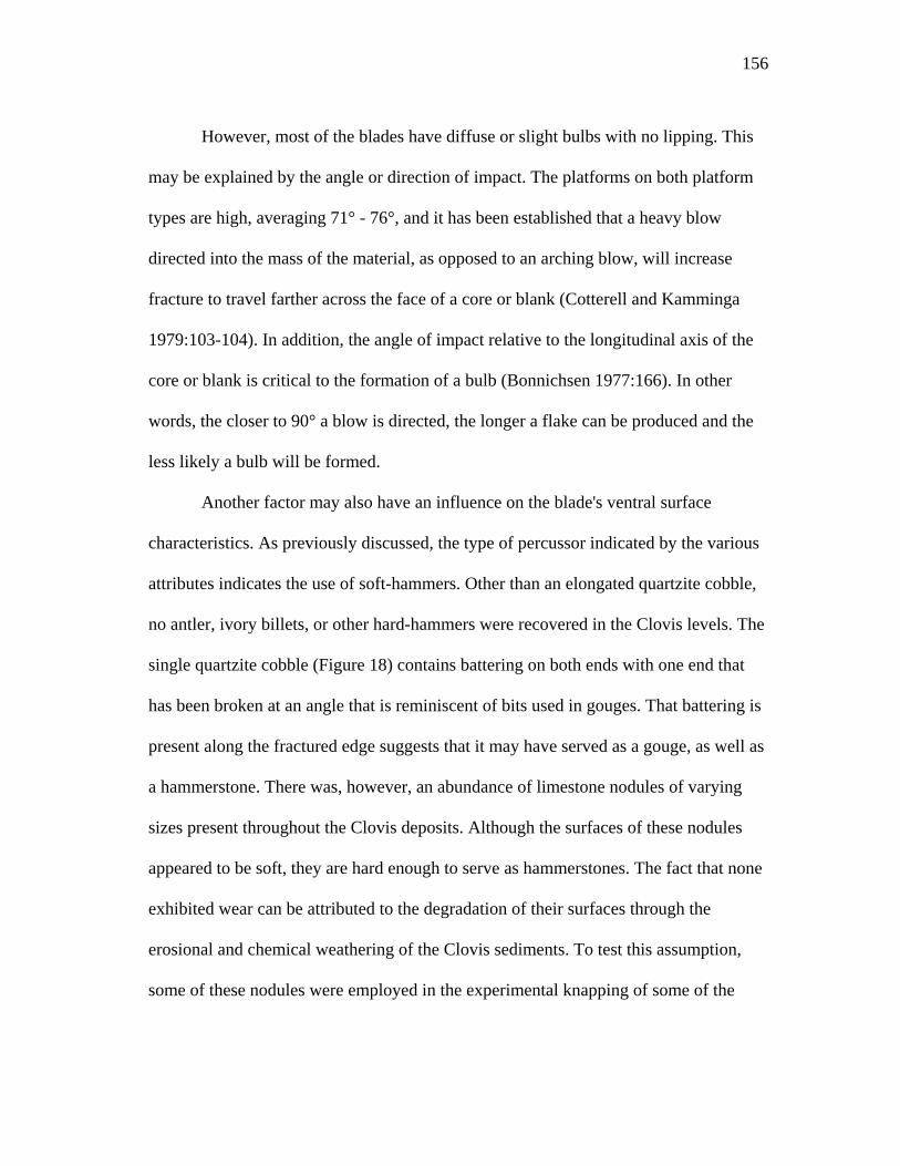
156
However, most of the blades have diffuse or slight bulbs with no lipping. This
may be explained by the angle or direction of impact. The platforms on both platform
types are high, averaging 71° - 76°, and it has been established that a heavy blow
directed into the mass of the material, as opposed to an arching blow, will increase
fracture to travel farther across the face of a core or blank (Cotterell and Kamminga
1979:103-104). In addition, the angle of impact relative to the longitudinal axis of the
core or blank is critical to the formation of a bulb (Bonnichsen 1977:166). In other
words, the closer to 90° a blow is directed, the longer a flake can be produced and the
less likely a bulb will be formed.
Another factor may also have an influence on the blade's ventral surface
characteristics. As previously discussed, the type of percussor indicated by the various
attributes indicates the use of soft-hammers. Other than an elongated quartzite cobble,
no antler, ivory billets, or other hard-hammers were recovered in the Clovis levels. The
single quartzite cobble (Figure 18) contains battering on both ends with one end that
has been broken at an angle that is reminiscent of bits used in gouges. That battering is
present along the fractured edge suggests that it may have served as a gouge, as well as
a hammerstone. There was, however, an abundance of limestone nodules of varying
sizes present throughout the Clovis deposits. Although the surfaces of these nodules
appeared to be soft, they are hard enough to serve as hammerstones. The fact that none
exhibited wear can be attributed to the degradation of their surfaces through the
erosional and chemical weathering of the Clovis sediments. To test this assumption,
some of these nodules were employed in the experimental knapping of some of the
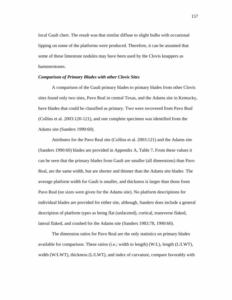
157
local Gault chert. The result was that similar diffuse to slight bulbs with occasional
lipping on some of the platforms were produced. Therefore, it can be assumed that
some of these limestone nodules may have been used by the Clovis knappers as
hammerstones.
Comparison of Primary Blades with other Clovis Sites
A comparison of the Gault primary blades to primary blades from other Clovis
sites found only two sites, Pavo Real in central Texas, and the Adams site in Kentucky,
have blades that could be classified as primary. Two were recovered from Pavo Real
(Collins et al. 2003:120-121), and one complete specimen was identified from the
Adams site (Sanders 1990:60).
Attributes for the Pavo Real site (Collins et al. 2003:121) and the Adams site
(Sanders 1990:60) blades are provided in Appendix A, Table 7. From these values it
can be seen that the primary blades from Gault are smaller (all dimensions) than Pavo
Real, are the same width, but are shorter and thinner than the Adams site blades The
average platform width for Gault is smaller, and thickness is larger than those from
Pavo Real (no sizes were given for the Adams site). No platform descriptions for
individual blades are provided for either site, although, Sanders does include a general
description of platform types as being flat (unfaceted), cortical, transverse flaked,
lateral flaked, and crushed for the Adams site (Sanders 1983:78, 1990:60).
The dimension ratios for Pavo Real are the only statistics on primary blades
available for comparison. These ratios (i.e.; width to length) (W:L), length (L/LWT),
width (W/LWT), thickness (L/LWT), and index of curvature, compare favorably with
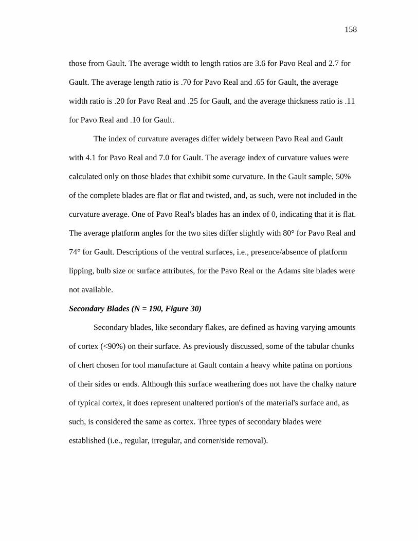
158
those from Gault. The average width to length ratios are 3.6 for Pavo Real and 2.7 for
Gault. The average length ratio is .70 for Pavo Real and .65 for Gault, the average
width ratio is .20 for Pavo Real and .25 for Gault, and the average thickness ratio is .11
for Pavo Real and .10 for Gault.
The index of curvature averages differ widely between Pavo Real and Gault
with 4.1 for Pavo Real and 7.0 for Gault. The average index of curvature values were
calculated only on those blades that exhibit some curvature. In the Gault sample, 50%
of the complete blades are flat or flat and twisted, and, as such, were not included in the
curvature average. One of Pavo Real's blades has an index of 0, indicating that it is flat.
The average platform angles for the two sites differ slightly with 80° for Pavo Real and
74° for Gault. Descriptions of the ventral surfaces, i.e., presence/absence of platform
lipping, bulb size or surface attributes, for the Pavo Real or the Adams site blades were
not available.
Secondary Blades (N = 190, Figure 30)
Secondary blades, like secondary flakes, are defined as having varying amounts
of cortex (<90%) on their surface. As previously discussed, some of the tabular chunks
of chert chosen for tool manufacture at Gault contain a heavy white patina on portions
of their sides or ends. Although this surface weathering does not have the chalky nature
of typical cortex, it does represent unaltered portion's of the material's surface and, as
such, is considered the same as cortex. Three types of secondary blades were
established (i.e., regular, irregular, and corner/side removal).
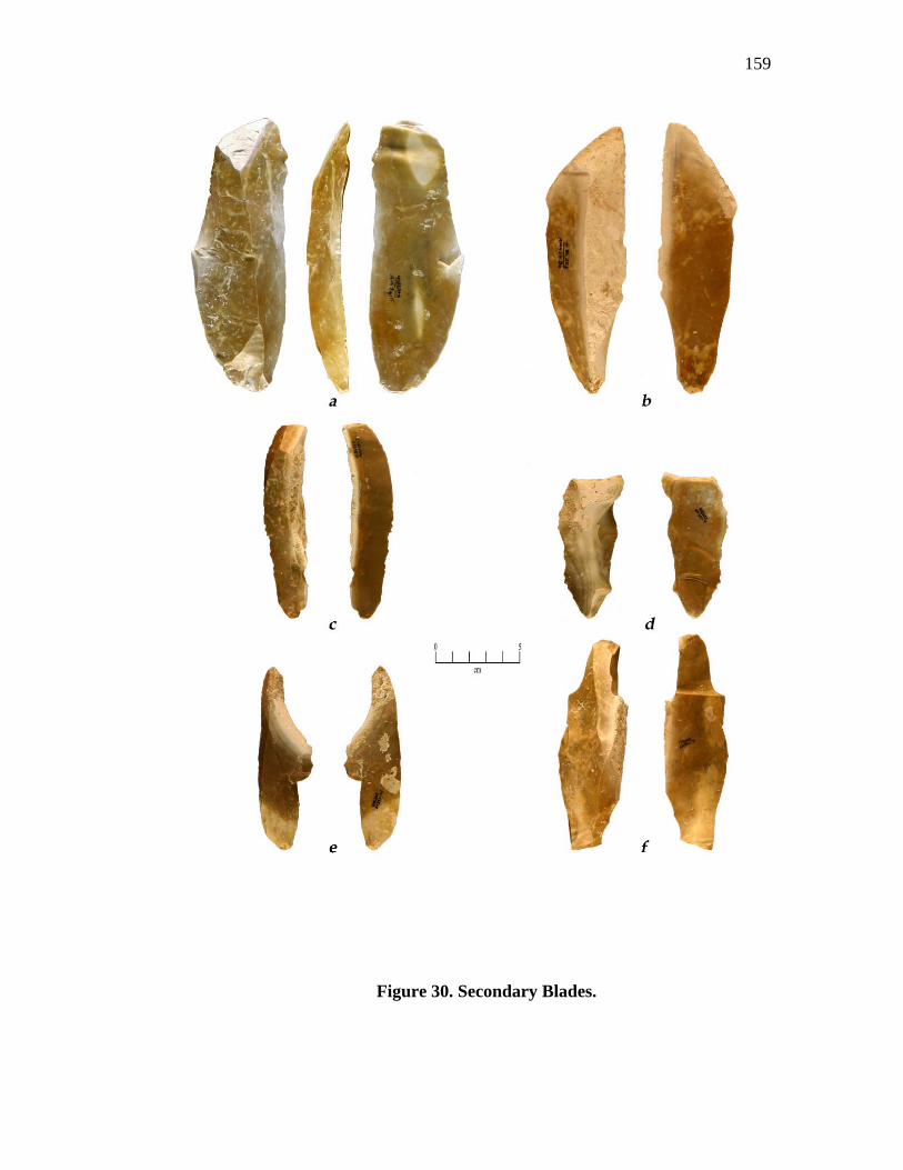
159
Figure 30. Secondary Blades.

160
Regular Secondary Blades (N = 57, Figure 30 a-c)
Regular secondary blades have more or less straight or contracting parallel
sides, but occasionally a bend to one side or the other (de bordant) is present on the
distal end. Cross sections may be flat, triangular, polyhedral with edges that range from
acute to abrupt. The dorsal scar patterns are, usually uni-directional or bi-directional,
but occasional radial patterns are noted. Profiles are flat, twisted, or incurvate, either
medially or distally.
Forty-nine of the regular secondary blades were complete enough to evaluate,
but eight were too fragmented or lacked their primary attributes to analyze. Of the 49
analyzed blades, 24 are complete, and the remaining 25 are broken. They range in
length between 41.5 mm and 163.9 mm with an average of 78.5 mm. Widths range
between 17.7 mm and 55.6 mm with an average of 22. 9mm, and thickness range
between 4.6 mm and 30.7 mm with an average of and 6.4 mm (Appendix A, Table 8).
Termination types include straight or blunt (18%), overshot or plunging (6%),
feathered (20%), and hinged (20%). The remainder (36%) are either broken or re-
worked (Appendix A, Table 8).
A number of platform types are present. Seven (14%) are natural, 15 (31%) are
plain, 3 (6%) are dihedral, 2 (4%) are polyhedral types, and the remaining 22 (45%)
have platforms that are missing or crushed. No platform preparation is evident on 28 of
the blades with platforms, but 11 are ground or abraded and another 11 are both
isolated and ground/abraded. Platform widths (all types) range between 3.0 mm and
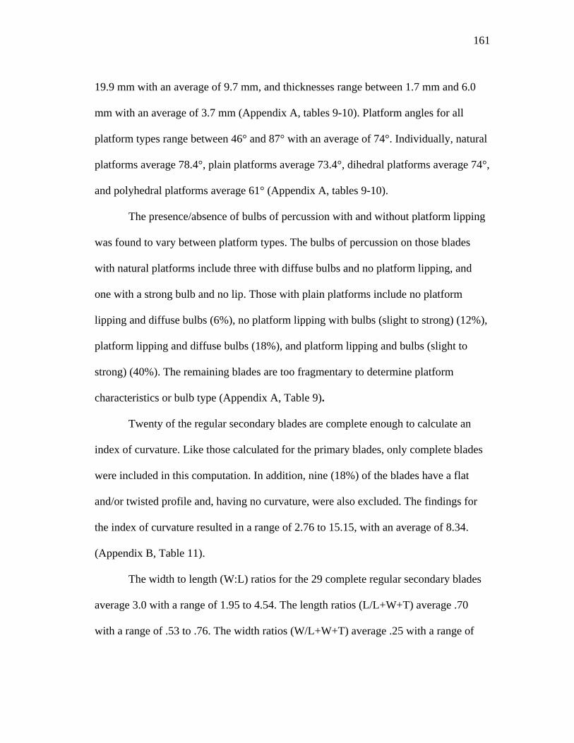
161
19.9 mm with an average of 9.7 mm, and thicknesses range between 1.7 mm and 6.0
mm with an average of 3.7 mm (Appendix A, tables 9-10). Platform angles for all
platform types range between 46° and 87° with an average of 74°. Individually, natural
platforms average 78.4°, plain platforms average 73.4°, dihedral platforms average 74°,
and polyhedral platforms average 61° (Appendix A, tables 9-10).
The presence/absence of bulbs of percussion with and without platform lipping
was found to vary between platform types. The bulbs of percussion on those blades
with natural platforms include three with diffuse bulbs and no platform lipping, and
one with a strong bulb and no lip. Those with plain platforms include no platform
lipping and diffuse bulbs (6%), no platform lipping with bulbs (slight to strong) (12%),
platform lipping and diffuse bulbs (18%), and platform lipping and bulbs (slight to
strong) (40%). The remaining blades are too fragmentary to determine platform
characteristics or bulb type (Appendix A, Table 9).
Twenty of the regular secondary blades are complete enough to calculate an
index of curvature. Like those calculated for the primary blades, only complete blades
were included in this computation. In addition, nine (18%) of the blades have a flat
and/or twisted profile and, having no curvature, were also excluded. The findings for
the index of curvature resulted in a range of 2.76 to 15.15, with an average of 8.34.
(Appendix B, Table 11).
The width to length (W:L) ratios for the 29 complete regular secondary blades
average 3.0 with a range of 1.95 to 4.54. The length ratios (L/L+W+T) average .70
with a range of .53 to .76. The width ratios (W/L+W+T) average .25 with a range of

162
.16 to .32, and the thickness ratios (T/L+W+T) average .08 with a range of .06 to .16.
Individual specimen tabulations and their totals for the width to length, length, width,
and thickness ratios are listed in Appendix A, Table 11).
The ventral surfaces on 28 (58%) of the regular secondary blades are smooth
with no ripples, although 8 (29%) of these also have slight to moderate waves.
Nineteen (40%) of the blades have slight to moderate ventral ripples with 15 (80%) of
these also having slight to moderate waves. Only one blade has strong ventral ripples,
which also contains a slight to moderate waves (Appendix A, Table 12).
The majority (57%) of these blades have a uni-directional dorsal scar pattern
with dorsal scar counts ranging from one to five scars. Bi-directional scar patterns
compose the next largest group comprising 29% of the total. A variety of patterns,
however, are noted within the bi-directional group. These include proximal-distal,
lateral-proximal, lateral-lateral, and lateral-proximal/distal patterns. In addition, these
blades are often a little thicker and less uniform than the uni-directional examples. The
remaining blades (14%) have dorsal scar patterns that are radial to sub-radial. Dorsal
scars within this group are smaller and more numerous, occasionally exceeding eight.
Many of these scars may represent cresting and edge straightening procedures
performed during initial core preparation or from failed or poor removals (Appendix A,
Table 8).
Although, there is an increase in platform preparation and smaller platforms,
the average platform angle of 74° and ventral surface attributes are much the same as
was noted on the primary blades (i.e., platform lipping combined with diffuse bulbs or
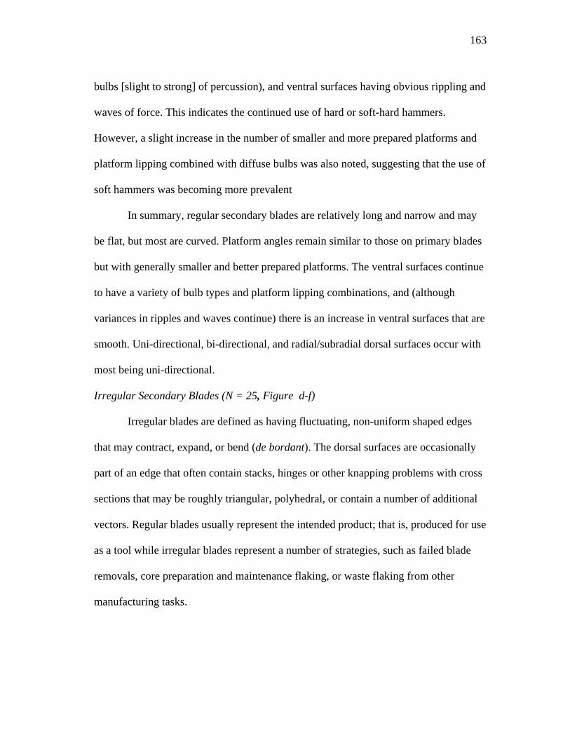
163
bulbs [slight to strong] of percussion), and ventral surfaces having obvious rippling and
waves of force. This indicates the continued use of hard or soft-hard hammers.
However, a slight increase in the number of smaller and more prepared platforms and
platform lipping combined with diffuse bulbs was also noted, suggesting that the use of
soft hammers was becoming more prevalent
In summary, regular secondary blades are relatively long and narrow and may
be flat, but most are curved. Platform angles remain similar to those on primary blades
but with generally smaller and better prepared platforms. The ventral surfaces continue
to have a variety of bulb types and platform lipping combinations, and (although
variances in ripples and waves continue) there is an increase in ventral surfaces that are
smooth. Uni-directional, bi-directional, and radial/subradial dorsal surfaces occur with
most being uni-directional.
Irregular Secondary Blades (N = 25, Figure d-f)
Irregular blades are defined as having fluctuating, non-uniform shaped edges
that may contract, expand, or bend (de bordant). The dorsal surfaces are occasionally
part of an edge that often contain stacks, hinges or other knapping problems with cross
sections that may be roughly triangular, polyhedral, or contain a number of additional
vectors. Regular blades usually represent the intended product; that is, produced for use
as a tool while irregular blades represent a number of strategies, such as failed blade
removals, core preparation and maintenance flaking, or waste flaking from other
manufacturing tasks.
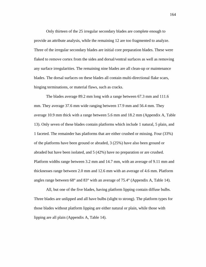
164
Only thirteen of the 25 irregular secondary blades are complete enough to
provide an attribute analysis, while the remaining 12 are too fragmented to analyze.
Three of the irregular secondary blades are initial core preparation blades. These were
flaked to remove cortex from the sides and dorsal/ventral surfaces as well as removing
any surface irregularities. The remaining nine blades are all clean-up or maintenance
blades. The dorsal surfaces on these blades all contain multi-directional flake scars,
hinging terminations, or material flaws, such as cracks.
The blades average 89.2 mm long with a range between 67.3 mm and 111.6
mm. They average 37.6 mm wide ranging between 17.9 mm and 56.4 mm. They
average 10.9 mm thick with a range between 5.6 mm and 18.2 mm (Appendix A, Table
13). Only seven of these blades contain platforms which include 1 natural, 5 plain, and
1 faceted. The remainder has platforms that are either crushed or missing. Four (33%)
of the platforms have been ground or abraded, 3 (25%) have also been ground or
abraded but have been isolated, and 5 (42%) have no preparation or are crushed.
Platform widths range between 3.2 mm and 14.7 mm, with an average of 9.11 mm and
thicknesses range between 2.0 mm and 12.6 mm with an average of 4.6 mm. Platform
angles range between 68° and 83° with an average of 75.4° (Appendix A, Table 14).
All, but one of the five blades, having platform lipping contain diffuse bulbs.
Three blades are unlipped and all have bulbs (slight to strong). The platform types for
those blades without platform lipping are either natural or plain, while those with
lipping are all plain (Appendix A, Table 14).
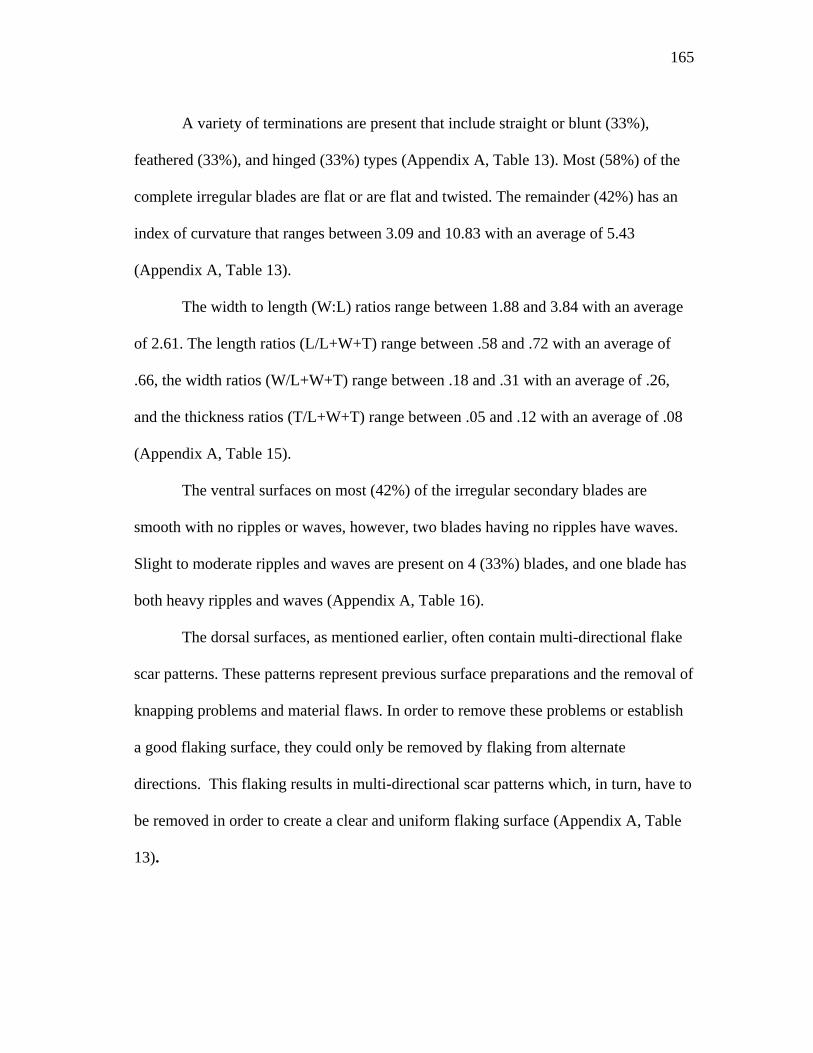
165
A variety of terminations are present that include straight or blunt (33%),
feathered (33%), and hinged (33%) types (Appendix A, Table 13). Most (58%) of the
complete irregular blades are flat or are flat and twisted. The remainder (42%) has an
index of curvature that ranges between 3.09 and 10.83 with an average of 5.43
(Appendix A, Table 13).
The width to length (W:L) ratios range between 1.88 and 3.84 with an average
of 2.61. The length ratios (L/L+W+T) range between .58 and .72 with an average of
.66, the width ratios (W/L+W+T) range between .18 and .31 with an average of .26,
and the thickness ratios (T/L+W+T) range between .05 and .12 with an average of .08
(Appendix A, Table 15).
The ventral surfaces on most (42%) of the irregular secondary blades are
smooth with no ripples or waves, however, two blades having no ripples have waves.
Slight to moderate ripples and waves are present on 4 (33%) blades, and one blade has
both heavy ripples and waves (Appendix A, Table 16).
The dorsal surfaces, as mentioned earlier, often contain multi-directional flake
scar patterns. These patterns represent previous surface preparations and the removal of
knapping problems and material flaws. In order to remove these problems or establish
a good flaking surface, they could only be removed by flaking from alternate
directions. This flaking results in multi-directional scar patterns which, in turn, have to
be removed in order to create a clear and uniform flaking surface (Appendix A, Table
13).
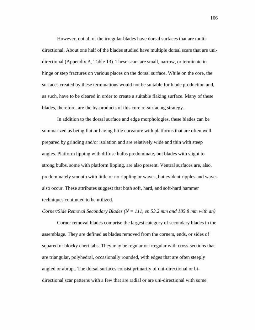
166
However, not all of the irregular blades have dorsal surfaces that are multi-
directional. About one half of the blades studied have multiple dorsal scars that are uni-
directional (Appendix A, Table 13). These scars are small, narrow, or terminate in
hinge or step fractures on various places on the dorsal surface. While on the core, the
surfaces created by these terminations would not be suitable for blade production and,
as such, have to be cleared in order to create a suitable flaking surface. Many of these
blades, therefore, are the by-products of this core re-surfacing strategy.
In addition to the dorsal surface and edge morphologies, these blades can be
summarized as being flat or having little curvature with platforms that are often well
prepared by grinding and/or isolation and are relatively wide and thin with steep
angles. Platform lipping with diffuse bulbs predominate, but blades with slight to
strong bulbs, some with platform lipping, are also present. Ventral surfaces are, also,
predominately smooth with little or no rippling or waves, but evident ripples and waves
also occur. These attributes suggest that both soft, hard, and soft-hard hammer
techniques continued to be utilized.
Corner/Side Removal Secondary Blades (N = 111, en 53.2 mm and 185.8 mm with an)
Corner removal blades comprise the largest category of secondary blades in the
assemblage. They are defined as blades removed from the corners, ends, or sides of
squared or blocky chert tabs. They may be regular or irregular with cross-sections that
are triangular, polyhedral, occasionally rounded, with edges that are often steeply
angled or abrupt. The dorsal surfaces consist primarily of uni-directional or bi-
directional scar patterns with a few that are radial or are uni-directional with some
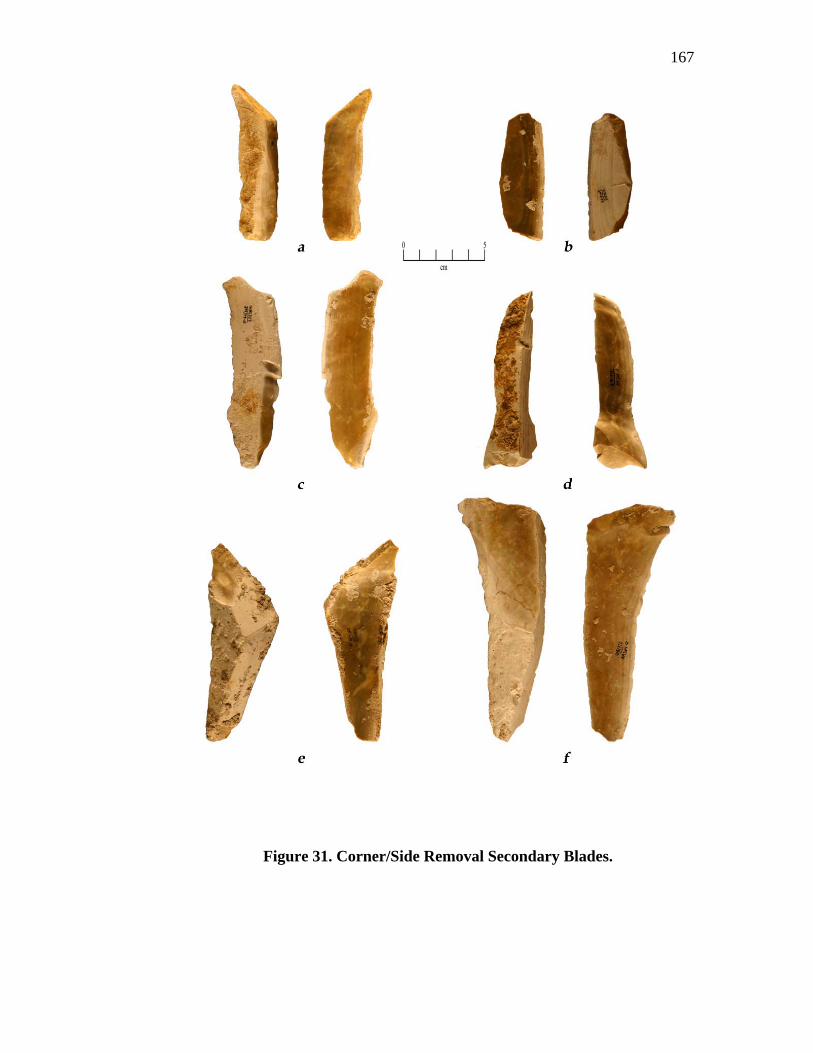
167
Figure 31. Corner/Side Removal Secondary Blades.
168
lateral flaking. On occasion, some of these blades contain a central blade scar bordered
by cortex on one or more sides. These represent cases where an attempt to remove the
corner resulted in only removing a small portion of the extreme edge of the tab.
Like the previous blade types, these blades represent a number of flaking
strategies. By far the more abundant secondary blade corner/side removal blades
represent core preparation or re-surfacing removals. Such blades were removed in both
initial bifacing and blade core preparation. These are identified by having dorsal
surfaces containing varying numbers of short removals, often originating laterally,
many ending in step or hinge type terminations, and edges that may be regular or
irregular.
Another type of secondary corner/side removal blades is a blade removed
during the primary blade production sequence. Secondary blades removed from conical
cores were produced only until the decortication of the cores surface continued. Once
this decortication process was complete, all blades produced were of the interior type.
Secondary blades detached from wedge-shaped cores, however, continued to be
produced until the core was exhausted or abandoned. For example, as each blade
removal sequence was completed and a proper flaking surface for the next set of
removals was established, the next series of blades removed would include blades from
each side (corner) of the core, as well as its interior. Those removed from the core’s
edges would retain varying amounts of cortex along one of the lateral edges. Along
with the interior blades, many of these secondary blades were the intended product
which would have been (and were) selected for tool use, the cortical "backing" along
169
one edge aiding in their grasping or holding capabilities. Because the same removal
strategy was utilized in core maintenance and primary blade removals, all the
secondary corner/side removal blade types were lumped together for the statistical
computations. Fifty-two blades were complete enough to provide width, length, and
thickness tabulations. The lengths range between 53.2 mm and 185.8 mm with an
average of 91.2 mm. Widths range between 17.3 mm and 52.6 mm with an average of
32.4 mm and the thicknesses range between 4.9 mm and 25.7 mm with an average of
14.5 mm (Appendix A, Table 17).
Thirty-seven of the blades contain identifiable platforms. These include 12
(32%) natural, 22 (60%) plain, and 3 (8%) dihedral. Platform widths (all types) have a
range of 3.5 - 22.6 mm with an average of 12.9 mm, and thicknesses of 1.6 mm - 9.5
mm with an average of 5.0 mm. Platform angles (all types) range between 53° and 85°
with an average of 73.3° (Appendix A, tables 18-19).
Two of the natural platforms and six of the plain platforms have been
ground/abraded. One natural, 6 plain, and all 3 of the dihedral platforms have been
both isolated and ground/abraded. The rest are un-modified (Appendix A, Table 18).
The majority (74%) of the platforms are unlipped with 14 (40%) having diffuse bulbs
and 12 (34%) with bulbs (slight to strong). Lipping (slight to strong) with diffuse bulbs
was noted on four (11%) blades (all plain platforms), and lipping with bulbs (slight to
strong) is present on five (14%) blades (three natural and three plain platform type)
(Appendix A, Table 18).
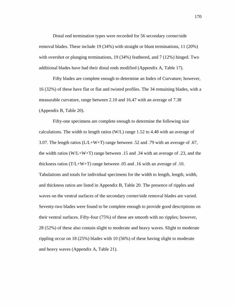
170
Distal end termination types were recorded for 56 secondary corner/side
removal blades. These include 19 (34%) with straight or blunt terminations, 11 (20%)
with overshot or plunging terminations, 19 (34%) feathered, and 7 (12%) hinged. Two
additional blades have had their distal ends modified (Appendix A, Table 17).
Fifty blades are complete enough to determine an Index of Curvature; however,
16 (32%) of these have flat or flat and twisted profiles. The 34 remaining blades, with a
measurable curvature, range between 2.10 and 16.47 with an average of 7.38
(Appendix B, Table 20).
Fifty-one specimens are complete enough to determine the following size
calculations. The width to length ratios (W/L) range 1.52 to 4.48 with an average of
3.07. The length ratios (L/L+W+T) range between .52 and .79 with an average of .67,
the width ratios (W/L+W+T) range between .15 and .34 with an average of .23, and the
thickness ratios (T/L+W+T) range between .05 and .16 with an average of .10.
Tabulations and totals for individual specimens for the width to length, length, width,
and thickness ratios are listed in Appendix B, Table 20. The presence of ripples and
waves on the ventral surfaces of the secondary corner/side removal blades are varied.
Seventy-two blades were found to be complete enough to provide good descriptions on
their ventral surfaces. Fifty-four (75%) of these are smooth with no ripples; however,
28 (52%) of these also contain slight to moderate and heavy waves. Slight to moderate
rippling occur on 18 (25%) blades with 10 (56%) of these having slight to moderate
and heavy waves (Appendix A, Table 21).
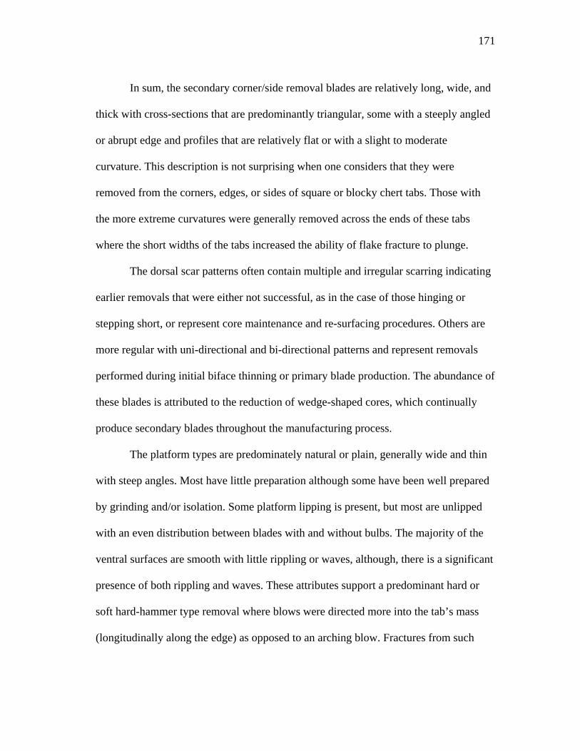
171
In sum, the secondary corner/side removal blades are relatively long, wide, and
thick with cross-sections that are predominantly triangular, some with a steeply angled
or abrupt edge and profiles that are relatively flat or with a slight to moderate
curvature. This description is not surprising when one considers that they were
removed from the corners, edges, or sides of square or blocky chert tabs. Those with
the more extreme curvatures were generally removed across the ends of these tabs
where the short widths of the tabs increased the ability of flake fracture to plunge.
The dorsal scar patterns often contain multiple and irregular scarring indicating
earlier removals that were either not successful, as in the case of those hinging or
stepping short, or represent core maintenance and re-surfacing procedures. Others are
more regular with uni-directional and bi-directional patterns and represent removals
performed during initial biface thinning or primary blade production. The abundance of
these blades is attributed to the reduction of wedge-shaped cores, which continually
produce secondary blades throughout the manufacturing process.
The platform types are predominately natural or plain, generally wide and thin
with steep angles. Most have little preparation although some have been well prepared
by grinding and/or isolation. Some platform lipping is present, but most are unlipped
with an even distribution between blades with and without bulbs. The majority of the
ventral surfaces are smooth with little rippling or waves, although, there is a significant
presence of both rippling and waves. These attributes support a predominant hard or
soft hard-hammer type removal where blows were directed more into the tab’s mass
(longitudinally along the edge) as opposed to an arching blow. Fractures from such
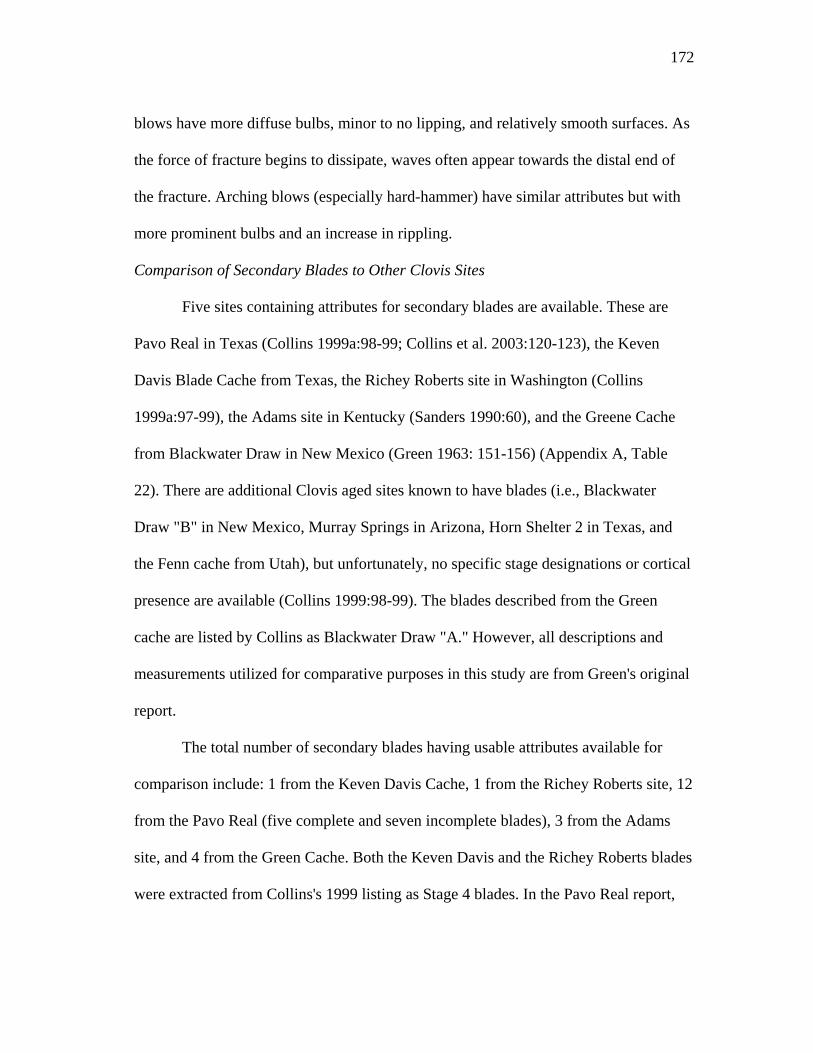
172
blows have more diffuse bulbs, minor to no lipping, and relatively smooth surfaces. As
the force of fracture begins to dissipate, waves often appear towards the distal end of
the fracture. Arching blows (especially hard-hammer) have similar attributes but with
more prominent bulbs and an increase in rippling.
Comparison of Secondary Blades to Other Clovis Sites
Five sites containing attributes for secondary blades are available. These are
Pavo Real in Texas (Collins 1999a:98-99; Collins et al. 2003:120-123), the Keven
Davis Blade Cache from Texas, the Richey Roberts site in Washington (Collins
1999a:97-99), the Adams site in Kentucky (Sanders 1990:60), and the Greene Cache
from Blackwater Draw in New Mexico (Green 1963: 151-156) (Appendix A, Table
22). There are additional Clovis aged sites known to have blades (i.e., Blackwater
Draw "B" in New Mexico, Murray Springs in Arizona, Horn Shelter 2 in Texas, and
the Fenn cache from Utah), but unfortunately, no specific stage designations or cortical
presence are available (Collins 1999:98-99). The blades described from the Green
cache are listed by Collins as Blackwater Draw "A." However, all descriptions and
measurements utilized for comparative purposes in this study are from Green's original
report.
The total number of secondary blades having usable attributes available for
comparison include: 1 from the Keven Davis Cache, 1 from the Richey Roberts site, 12
from the Pavo Real (five complete and seven incomplete blades), 3 from the Adams
site, and 4 from the Green Cache. Both the Keven Davis and the Richey Roberts blades
were extracted from Collins's 1999 listing as Stage 4 blades. In the Pavo Real report,
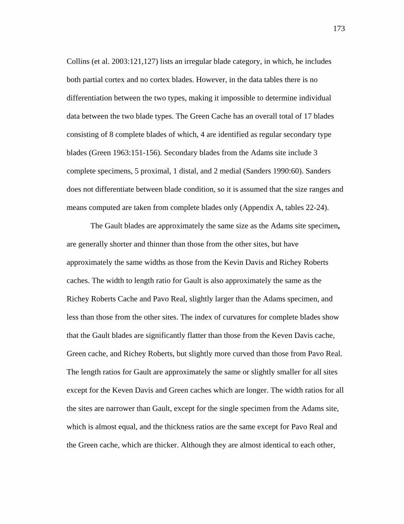
173
Collins (et al. 2003:121,127) lists an irregular blade category, in which, he includes
both partial cortex and no cortex blades. However, in the data tables there is no
differentiation between the two types, making it impossible to determine individual
data between the two blade types. The Green Cache has an overall total of 17 blades
consisting of 8 complete blades of which, 4 are identified as regular secondary type
blades (Green 1963:151-156). Secondary blades from the Adams site include 3
complete specimens, 5 proximal, 1 distal, and 2 medial (Sanders 1990:60). Sanders
does not differentiate between blade condition, so it is assumed that the size ranges and
means computed are taken from complete blades only (Appendix A, tables 22-24).
The Gault blades are approximately the same size as the Adams site specimen,
are generally shorter and thinner than those from the other sites, but have
approximately the same widths as those from the Kevin Davis and Richey Roberts
caches. The width to length ratio for Gault is also approximately the same as the
Richey Roberts Cache and Pavo Real, slightly larger than the Adams specimen, and
less than those from the other sites. The index of curvatures for complete blades show
that the Gault blades are significantly flatter than those from the Keven Davis cache,
Green cache, and Richey Roberts, but slightly more curved than those from Pavo Real.
The length ratios for Gault are approximately the same or slightly smaller for all sites
except for the Keven Davis and Green caches which are longer. The width ratios for all
the sites are narrower than Gault, except for the single specimen from the Adams site,
which is almost equal, and the thickness ratios are the same except for Pavo Real and
the Green cache, which are thicker. Although they are almost identical to each other,
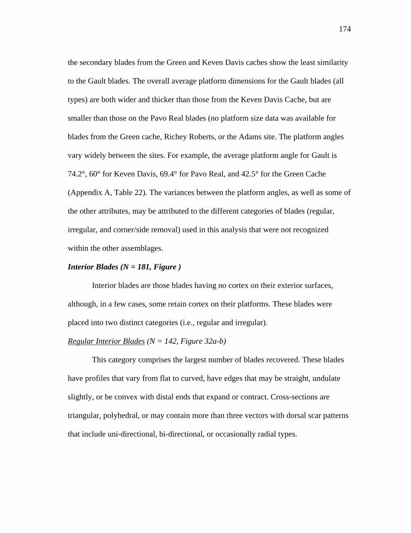
174
the secondary blades from the Green and Keven Davis caches show the least similarity
to the Gault blades. The overall average platform dimensions for the Gault blades (all
types) are both wider and thicker than those from the Keven Davis Cache, but are
smaller than those on the Pavo Real blades (no platform size data was available for
blades from the Green cache, Richey Roberts, or the Adams site. The platform angles
vary widely between the sites. For example, the average platform angle for Gault is
74.2°, 60° for Keven Davis, 69.4° for Pavo Real, and 42.5° for the Green Cache
(Appendix A, Table 22). The variances between the platform angles, as well as some of
the other attributes, may be attributed to the different categories of blades (regular,
irregular, and corner/side removal) used in this analysis that were not recognized
within the other assemblages.
Interior Blades (N = 181, Figure )
Interior blades are those blades having no cortex on their exterior surfaces,
although, in a few cases, some retain cortex on their platforms. These blades were
placed into two distinct categories (i.e., regular and irregular).
Regular Interior Blades (N = 142, Figure 32a-b)
This category comprises the largest number of blades recovered. These blades
have profiles that vary from flat to curved, have edges that may be straight, undulate
slightly, or be convex with distal ends that expand or contract. Cross-sections are
triangular, polyhedral, or may contain more than three vectors with dorsal scar patterns
that include uni-directional, bi-directional, or occasionally radial types.
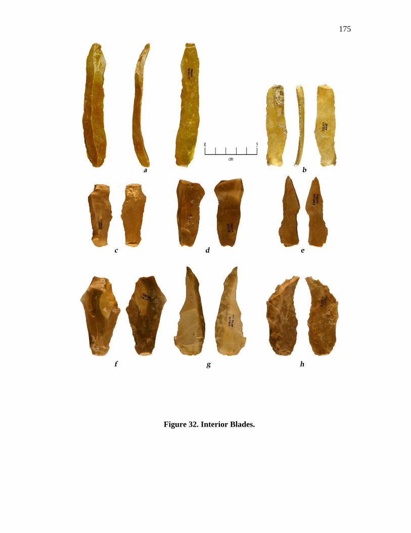
175
Figure 32. Interior Blades.
176
The condition of these blades can be broken down as follows: 45 complete
blades, 22 proximal, 16 distal, 39 medial, 9 medial-distal, and 11 medial proximal
sections. Sizes range from 49.8 mm to 111.9 mm in length averaging 95.7 mm. The
widths range from 11.5 mm to 48.2 mm with an average of 22.0 mm, and thickness
ranges from 2.9 mm to 18.9 mm averaging 8.9 mm (Appendix A, Table 25). Feathered
(51%) and straight or blunt (25%) terminations make up the majority of the termination
types, followed by hinged (20%) and overshot (4%) terminations (Appendix A, Table
25).
The majority (43%) of the platforms are plain. Dihedral platforms are the next
abundant (17%), followed with polyhedral/faceted (10%) and natural (4%) types. The
remainder is crushed, reworked, or undetermined (Appendix A, Table 26). Fifty
percent of the platforms are both ground/abraded and isolated, followed by 24% with
only ground or abraded platforms, 4% isolated, and 2% having no preparation
(Appendix A, Table 26). The platform widths range from 2.4 mm to 14.1 mm with an
average of 10.7 mm and thicknesses ranging from 1.3 mm to 5.22 mm with an average
of 2.9 mm. Platform angles are widely varied ranging between 38° and 89° with an
average of 68.5° (Appendix A, tables 26-27).
Platform lipping is present on 62% of the regular interior blades (all platform
types), but varies on the presence of bulbs of percussion. Forty-seven percent of the
blades have lipping (slight to strong) but no bulbs (diffuse), and blades with lipping
and bulbs (slight to strong) occur on only 15%. No lipping with diffuse bulbs was
177
found on 18%, and no lipping with bulbs (slight to strong) present included 15%. The
remainder has platform characteristics or bulbs that are undetermined (Appendix A,
Table 26).
Thirty-seven blades are complete enough to calculate the index of curvature;
however, 12 (32%) of these are flat or twisted and have no curvature. The index of
curvature for the remaining 25 complete blades (68%) with a measurable curvature
range between 3.17 and 14.88 has an average of 7.61 (Appendix B, Table 28). Of those
blades with the greatest curvature (i.e., exceeding 9.00), only one appears to have been
removed from the corner/end of a core, having a strongly angled dorsal surface. The
others contain uniform continuous curvatures on their dorsal surfaces.
Briefly, the width to length ratio (W:L) averages 3.71 with a range of 2.15 -
7.84. The length ratio (L/LWT) averages .71 with a range of .56 - .82, the width ratio
(W/LWT) averages .21 with a range of .11 - .36, and the thickness (T/LWT) ratio
averages .08 with a range of .04 - .13 (Appendix A, Table 28).
The ventral surfaces of these blades are smoother with fewer waves than was
seen on the previous blade categories. These surfaces showed that 57% have no ripples
or waves and another 18% with no ripples and only minor waves. Obvious rippling
combined with varying degrees of waves was noted on only 13% of the blades
(Appendix A, Table 29).
As was indicated in the initial interior blade description, the dorsal scar patterns
on these blades include uni-directional, bi-directional, or radial patterns. The uni-
directional pattern is, by far, the most abundant with 55% of the blades exhibiting this
178
characteristic. The basic bi-directional pattern; that is, one that contains both proximal
and distal initiated scars, was noted on 18% of the blades. Interestingly, an additional
18% of the blades contain another type of bi-directional pattern where scars may
initiate from either end but also contain laterally initiated scars. These laterally directed
scars may or may not initiate on the blades edge, most often originating from another
part of the core. The least noted scar pattern was the radial/subradial type with only 8%
exhibiting this pattern.
Irregular Interior Blades (N =142, Figure 32 a-b)
These blades are primarily core maintenance and problem removals, or failed
regular blade removals. They are defined as having lateral edges that are erratic and
jagged, often bending severely to one side or the other. Cross-sections vary from
triangular to having many vectors, often with one side being very steeply angled or
abrupt. The dorsal surfaces may have as few as two or three longitudinal scars, but
more often have four or more scars in radial or bi-directional-lateral patterns, some, of
which, end in step or hinge terminations.
This group includes 19 complete blades, 5 proximal, 10 distal, 3 medial, and 3
medial-distal fragments. Sizes range 40.0 mm - 78.0 mm in length with an average of
62.7 mm. Widths are between 11.5 mm - 39.3 mm with an average of 24.5 mm, and
thicknesses between 5.0 mm - 11.6 mm with an average of 7.8mm (Appendix A, Table
30). Blade terminations include 44% feathered, 25% straight or blunt, 13% hinged, the
rest are broken or re-worked (Appendix A, Table 30).
179
Seventy percent of the platforms are plain; 15% natural, 5% are polyhedral, and
10% are crushed (Appendix A, Table 31). Forty-four percent of the platforms have
been ground and isolated, 22% are ground or abraded only, 11% isolated, and 22%
have no modification (Appendix A, Table 31). Platform widths average 10.7mm wide
with a range of 6.4mm to 15.6mm, and thicknesses average 4.0mm with a range of
2.0mm to 5.8mm. Platform angles average 68.3° with a range between 60° and 81°
(Appendix A, Table 31).
The presence/absence of platform lipping and the bulbs of percussion are
closely split. Platform lipping with diffuse bulbs are present on 31%, and lipping
combined with bulbs (slight to strong) are present on 20% of the blades. On the other
hand, 28% of the blades have no lipping and bulbs (slight to strong), and 22% have no
lipping with diffuse bulbs (Appendix A, Table 31).
Eleven of the irregular blades are complete enough to compute the index of
curvature; however, 5 (45%) of these are flat. The remaining six blades (55%) with a
measurable curvature have an index that averages 7.48 with a range of 3.62 to 12.87.
Only two blades exceed an index of 9.00, these being 10.11 and 12.87, the latter being
the only corner removal within this category (Appendix A, Table 32).
Dimension ratios were calculated on 13 of the irregular interior blades. The
calculations for width to length ratio (W:L) averaged 2.40 with a range of 1.65 - 3.46.
However, these figures include three very short, almost flake-like blades. They were all
prepared and struck off in the same manner as the other blades, but terminated short. If
they were eliminated from the width to length ratio, the average is raised to 2.56. The
180
length ratio (L\LWT) averaged .60 with a range of .58 - .74, the width ratio (W\LWT)
averaged .28 with a range of .21 - .35, and the thickness ratio (T\LWT) averages .08
with a range of .05 - .11 (Appendix A, Table 32).
The ventral surfaces of these blades are, like the regular blades, predominately
smooth with little rippling or waves. No ripples or waves were found on 27%, no
ripples with waves (slight to moderate and strong) were found on 46%. Ripples (all
types) combined with waves (all types) was seen on 20% and the remaining 7% have
no waves (Appendix A, Table 33).
The major dorsal scar pattern noted on the irregular blades is the bi-directional
type that has lateral directed scars combined with either proximal or distal directed
scarring. This type comprised 44% of the total, and was followed by a radial or
subradial type with 22%. The proximal-distal bi-direction type comprised 11% and a
lateral bi-direction type was noted on the remaining 11% (Appendix A, Table 30).
To summarize the interior blades, both the regular and irregular forms have
profiles that vary from flat to gently curved, with a few examples that are strongly
curved. The regular blades are slightly longer than the irregular blades, which is
understandable when considering that the irregular forms were produced primarily as
core maintenance, re-surfacing removals, or are failed primary blade removals as
opposed to the regular blades which were more of the intended end product. These
differences are also supported by the dorsal scar patterns, which are significantly more
complicated on the irregular blades.
181
The platforms are well prepared by isolating and grinding, but (although plain
platforms dominate) they are closely followed by dihedral and faceted types. Platform
sizes on both forms are fairly small, with both forms having approximately the same
widths, but are thicker on the irregular blades. Although still fairly steep, the platform
angles are less than those recorded for both the primary and secondary blades.
The ventral surfaces are smooth with little rippling or waves noted on either of
the forms. There is an increase in platform lipping with diffuse bulbs in secondary
blades. Lipping, combined with bulbs of all types, and no lipping, with and without
bulbs, are well represented between both blade forms. The combination of these
attributes suggests that both soft and hard hammers continued to be utilized for blade
removal. However, the decrease in platform angle and an increase in platform lipping
combined with diffuse bulbs are an indication of an increase in soft-hammer use.
Comparison of Interior Blades to Other Clovis Sites
Six sites were found to have attributes available for a comparison of interior
blades (Appendix A, Tables 34-36). These sites include the Green Cache from
Blackwater Draw, New Mexico (Green 1963:151-156), the Keven Davis Blade Cache
from Central Texas, Richey Roberts from Washington, Gault 1 from Central Texas
(Collins 1999a:97-103), Pavo Real from central Texas (Collins et al. 2003:126), and
the Adams site from Kentucky (Sanders 1990:60). The Gault specimens were obtained
from an earlier study conducted by UT.
As with the secondary blades, a considerably larger sample of interior blades
was available than those for any previous study which, like the secondary blades,
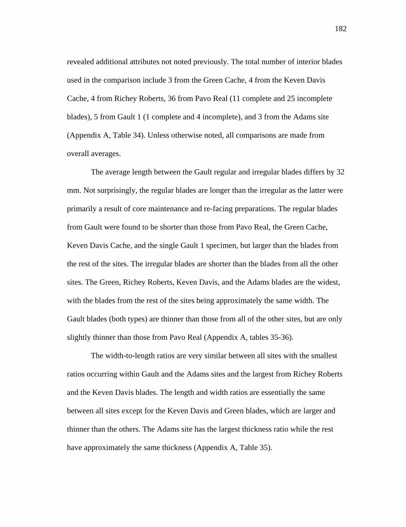
182
revealed additional attributes not noted previously. The total number of interior blades
used in the comparison include 3 from the Green Cache, 4 from the Keven Davis
Cache, 4 from Richey Roberts, 36 from Pavo Real (11 complete and 25 incomplete
blades), 5 from Gault 1 (1 complete and 4 incomplete), and 3 from the Adams site
(Appendix A, Table 34). Unless otherwise noted, all comparisons are made from
overall averages.
The average length between the Gault regular and irregular blades differs by 32
mm. Not surprisingly, the regular blades are longer than the irregular as the latter were
primarily a result of core maintenance and re-facing preparations. The regular blades
from Gault were found to be shorter than those from Pavo Real, the Green Cache,
Keven Davis Cache, and the single Gault 1 specimen, but larger than the blades from
the rest of the sites. The irregular blades are shorter than the blades from all the other
sites. The Green, Richey Roberts, Keven Davis, and the Adams blades are the widest,
with the blades from the rest of the sites being approximately the same width. The
Gault blades (both types) are thinner than those from all of the other sites, but are only
slightly thinner than those from Pavo Real (Appendix A, tables 35-36).
The width-to-length ratios are very similar between all sites with the smallest
ratios occurring within Gault and the Adams sites and the largest from Richey Roberts
and the Keven Davis blades. The length and width ratios are essentially the same
between all sites except for the Keven Davis and Green blades, which are larger and
thinner than the others. The Adams site has the largest thickness ratio while the rest
have approximately the same thickness (Appendix A, Table 35).
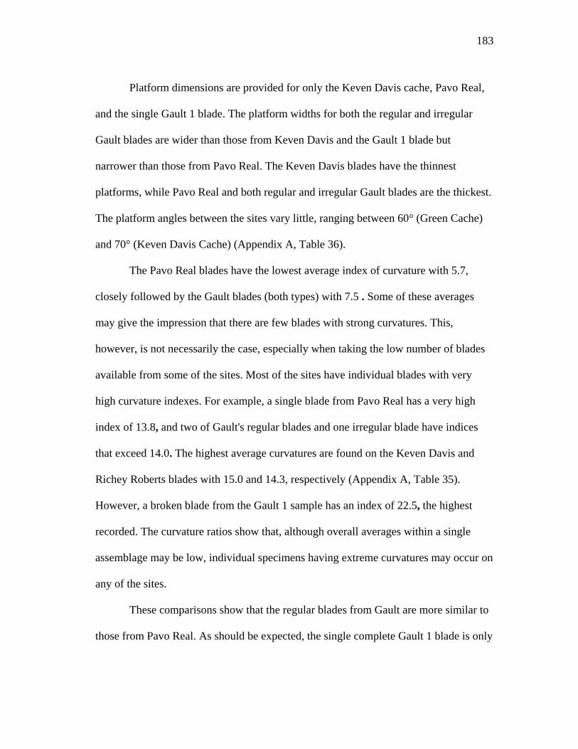
183
Platform dimensions are provided for only the Keven Davis cache, Pavo Real,
and the single Gault 1 blade. The platform widths for both the regular and irregular
Gault blades are wider than those from Keven Davis and the Gault 1 blade but
narrower than those from Pavo Real. The Keven Davis blades have the thinnest
platforms, while Pavo Real and both regular and irregular Gault blades are the thickest.
The platform angles between the sites vary little, ranging between 60° (Green Cache)
and 70° (Keven Davis Cache) (Appendix A, Table 36).
The Pavo Real blades have the lowest average index of curvature with 5.7,
closely followed by the Gault blades (both types) with 7.5 . Some of these averages
may give the impression that there are few blades with strong curvatures. This,
however, is not necessarily the case, especially when taking the low number of blades
available from some of the sites. Most of the sites have individual blades with very
high curvature indexes. For example, a single blade from Pavo Real has a very high
index of 13.8, and two of Gault's regular blades and one irregular blade have indices
that exceed 14.0. The highest average curvatures are found on the Keven Davis and
Richey Roberts blades with 15.0 and 14.3, respectively (Appendix A, Table 35).
However, a broken blade from the Gault 1 sample has an index of 22.5, the highest
recorded. The curvature ratios show that, although overall averages within a single
assemblage may be low, individual specimens having extreme curvatures may occur on
any of the sites.
These comparisons show that the regular blades from Gault are more similar to
those from Pavo Real. As should be expected, the single complete Gault 1 blade is only
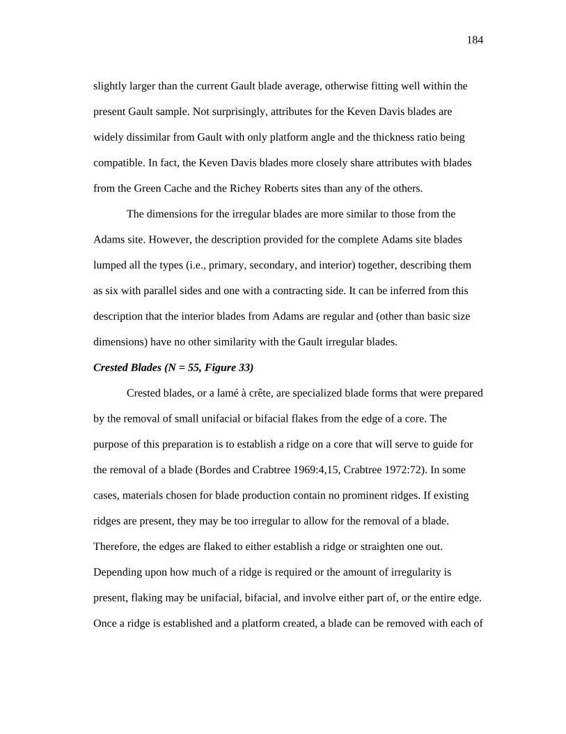
184
slightly larger than the current Gault blade average, otherwise fitting well within the
present Gault sample. Not surprisingly, attributes for the Keven Davis blades are
widely dissimilar from Gault with only platform angle and the thickness ratio being
compatible. In fact, the Keven Davis blades more closely share attributes with blades
from the Green Cache and the Richey Roberts sites than any of the others.
The dimensions for the irregular blades are more similar to those from the
Adams site. However, the description provided for the complete Adams site blades
lumped all the types (i.e., primary, secondary, and interior) together, describing them
as six with parallel sides and one with a contracting side. It can be inferred from this
description that the interior blades from Adams are regular and (other than basic size
dimensions) have no other similarity with the Gault irregular blades.
Crested Blades (N = 55, Figure 33)
Crested blades, or a lamé à crête, are specialized blade forms that were prepared
by the removal of small unifacial or bifacial flakes from the edge of a core. The
purpose of this preparation is to establish a ridge on a core that will serve to guide for
the removal of a blade (Bordes and Crabtree 1969:4,15, Crabtree 1972:72). In some
cases, materials chosen for blade production contain no prominent ridges. If existing
ridges are present, they may be too irregular to allow for the removal of a blade.
Therefore, the edges are flaked to either establish a ridge or straighten one out.
Depending upon how much of a ridge is required or the amount of irregularity is
present, flaking may be unifacial, bifacial, and involve either part of, or the entire edge.
Once a ridge is established and a platform created, a blade can be removed with each of
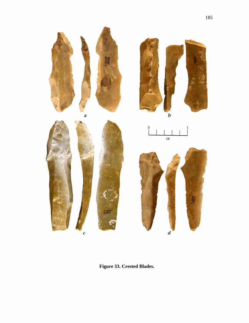
185
Figure 33. Crested Blades.
186
the lateral edges forming an additional guide ridge for additional blade removals.
proportional to the thickness of the platform and force of blow. In cases where this
removal is not wide or long enough, additional flakes, or flaking from the opposite end
may be required. If successful, an angle suitable for lateral flaking (crest formation)
will be established along the side of the core.
This process is usually considered only as evidence for blade core preparation,
but during the analysis of the Gault bifaces it was found that it was also employed
during initial biface reduction as well. The cresting along the edge of a cobble or
blocky tab serves the same purpose in establishing an edge for bifacing as it does in
setting up ridges for blade production. Blocky tabs often have edges that are irregular
or contain some material defects that inhibit or reduce length of fracture. The technique
of cresting was employed in order to clear these problems and establish a surface or
edge suitable enough to remove a flake along the tabs entire length. Once a ridge is
aligned along an edge, the entire corner (or side) can be removed creating a surface that
angles toward the opposite face. This brings the two faces close together allowing for
the formation of platforms, at various points along the fractured surface, which will
enable transverse flaking across the surface of the blank. This differs from the repeated
longitudinal flaking along one or more axes on cores used in blade production.
Unfortunately, there is no differentiation between individual crested blades identifying
their removal from either process. However, the use of cresting in biface reduction was
established from flake scar patterns noted on overshot and some large flakes associated
in biface thinning.
187
Typically, the crests are formed by removing flakes from a common edge.
Within the Gault sample, 50% of the crested blades have an edge that was entirely
flaked unifacially and 37% were flaked bifacially, 9% have sides that were only
partially flaked, and (in 4% of the sample), one side was entirely flaked and only a part
of the opposite side was flaked. In a few cases (10%), some flaking originated laterally,
and terminated on the crested edge. It was found that 78% of the Gault crested blades
have had previous removals performed, with 50% of these having multiple removals,
some from both ends (Appendix A, Table 37). Those with flaking originating from
another edge may have been to aid in edge straightening, as well as for establishing a
flakable edge.
The condition of the crested blades includes 19 complete blades, 2 proximal, 11
distal 10 medial, 5 proximal-medial, and 8 medial-distal sections. Blade shapes are
highly varied and may be regular, expanding, converging, bending, and asymmetrical,
but most (59%) are irregular. As would be expected, cross-sections are primarily
triangular (91%), but many of these (43%) have one lateral edge that is abrupt (lateral
steep). Edge angles on the abrupt side often exceed 75° with a high angle of 111°
(Appendix A, Table 38). Most blades bend slightly medially or distally, but 30% of the
sample are flat or twisted with no curvature.
The Gault crested blades average 97.9 mm long with a range of 43.3 mm -
165.6 mm. Widths average 29.6 mm with ranges of 13.4 mm - 48.7 mm, and thickness
averages 16.2 mm with a range of 10.6 mm - 28.8 mm (Appendix A, Table 39).
188
Termination types include straight or blunt (54%), feathered (24%), hinged (11%), and
plunging or overshot (11%) (Appendix B, Table 39).
Many of the platforms are missing (48%) or crushed (7%) but (of those
containing platforms) the majority are plain (24%), followed by natural (13%), dihedral
(7%), and faceted (2%) types (Appendix A, Table 40). Eleven percent of the platforms
are ground or abraded, 13% are ground/abraded and isolated, 19% have no preparation,
and preparation on the remainder (57%) cannot be determined due to missing or
damaged platforms. Platform widths (all types) range 4.0 mm - 27.5 mm with an
average of 9.3 mm, and thicknesses range 2.4 mm - 12.1 mm and average 4.8 mm.
Platform angles are usually steep with a range between 48° and 89° and an average of
72.5° (Appendix A, tables 40-41).
Twenty blades retain platform and bulb characteristics. Platform lipping is
present on seven (35%) of the crested blades, but vary on the presence of bulbs.
Lipping on blades with diffuse bulbs were noted on only 3 (15%), lipping with bulbs
(all types) were found on 4 (20%) of the blades. No lipping with diffuse bulbs was
found on three (15%) of the blades, and no lipping with bulbs (all types) is present on
10 (50%) of the blades (Appendix A, Table 40).
Forty-two of the blades were complete enough to calculate the index of
curvature. However, as mentioned above, 30% (N = 14) of the blades are flat and/or
twisted and have no curvature. The index of curvature on the remaining 28 blades
ranges between 3.46 and 13.44 with an average of 7.97 (Appendix A, Table 42). The
strongest curvatures (i.e., those having an index exceeding 9.00) were found on only
189
five blades. Three of these are on the longest blades, whose lengths range between 100
mm and 124 mm, while the other two are among the shortest, ranging between 43.3
mm and 46.6 mm in length. The longer blades were obviously removed along the long
axis of a tab but the shorter blades were vertical removals from the corners of
moderately thick tabs.
The width to length ratio (W:L) averages 3.40 with a range of 1.91 - 5.91. The
low figure of 1.9 is from one of the short vertical corner removal blades mentioned
above. This blade has a very irregular or asymmetrical outline resembling more of a
blade-like flake than a true blade, but due to the presence of prominent cresting on its
dorsal surface, it is included within this sample. The length ratio (L/LWT) averages .68
with a range of .56 - .74, the width ratio (W/LWT) averages .21 with a range of .13 -
.30, and the thickness ratio (T/LWT) averages .11 with a range of .06 - .15 (Appendix
A, Table 42).
Although ventral rippling is present, the ventral surfaces of 81% of the sample
are predominately smooth with no or little rippling and no or minor waves (Appendix
B, Table 43). This is interesting when considering the findings that 53% of the blades
have no platform lipping and moderately strong to strong bulbs and 16% have no
lipping and diffuse bulbs. These attributes and the high platform angles indicate that at
this stage of manufacture the angle of impact was directed into the mass (along the
edge) as opposed to an arching swing. Fractures from such impacts result in smooth
ventral surfaces having minor or no lipping and are an indication of the use of hard and
soft-hard hammer percussion. The use of soft hammers, however, also produces similar
190
attributes, especially on those blades with smooth ventral surfaces combined with
prominent lipping and diffuse bulbs. The combination of these attributes was noted on
only three (7%) of the blades, therefore, the use of soft hammer percussion should also
be considered as an additional method for flake removal.
Summarizing the crested blades, the Gault specimens comprise some of the
larger blades in the overall blade assemblage as well as some of the shortest. The dorsal
scar patterns contain specimens that are unifacial, bifacial, contain portions that are
both unifacial and bifacial, and contain some with flaking only on part of the blade.
Many of the specimens also exhibit previous blade removals, albeit, some terminating
short of the blades total length. Profiles range from flat and twisted to some with
moderate medial and distal bending with a few examples that are more strongly curved.
The cross-sections are usually triangular, but the overall shapes vary, with most being
irregular. The platforms are moderate to large and are often well prepared by isolating
and grinding. The ventral surfaces are usually smooth with little rippling or waves,
have slight to no platform lipping and bulbs that may be diffuse to moderately strong.
Comparison of Crested Blades to Other Clovis Sites.
Crested blades are known from three established Clovis sites (Appendix A,
Table 44) (i.e., Keven Davis Cache from Central Texas, Pavo Real from Central Texas,
and the Green Cache from Blackwater Draw, New Mexico). In addition, blades from
two additional sites (i.e., 41RN107, an open site located in the Colorado River valley
of west-central Texas, and Anadarko in Oklahoma), described as containing probable
and indefinite Clovis contexts (Collins 1999a:97-101) were referenced. Three blades
191
are listed from the Keven Davis site, two from Pavo Real, and two from Green. A
single complete blade was recovered from 41RN107, a site from which Early Archaic,
Folsom, Midland, and Plainview artifacts have been recovered (Bryan and Collins
1988). Among the artifacts recovered were a tip and a complete patinated blade, having
attributes comparable to Clovis blades. The Anadarko blades are from a cache of
blades, having similar Clovis blade attributes (Collins 1999a:166) that were excavated
from a corral near Anadarko, Oklahoma (Hammatt 1970). Within this assemblage were
two blades, described as Stage 2 blades or secondary blades with prepared crests
(Collins 1999:90). These two sites are not considered as having good Clovis contexts,
but due to the scarcity of recorded crested blades, they are included here for a
comparison.
A comparison of the attribute averages and ranges for each of the sites with
Gault is provided in Appendix A, tables 45-46. It can be seen from these tables that the
Gault specimens more closely resemble those from Pavo Real and RN107 and are most
dissimilar with the blades from the Keven Davis cache and Anadarko. Unfortunately,
not all attributes are available for blades from the Green cache, where only a few
measurements for each blade are available. Those that are, i.e., blade width and
thickness, are very comparable to Gault.
Blade Cores
A total of 46 blade cores (all types) were recovered during the excavations
carried out by TAMU. In addition to these cores, a blocky core was refitted with three
blade-like flakes; however, this specimen will be discussed later in the section on
192
reitted pieces. The core types consist of 3 conical cores, 31 wedge-shaped cores, and 10
cores miscellaneous irregular cores and core fragments.
Conical Cores (N = 3, Figure 34 and 35)
These cores are defined by Collins (1999a:51) as having the blade facets on the
long axis of the core at approximate right angles to the platform plane and most of the
core's circumference flaked. The angles on the Gault specimens easily fall within this
description, ranging from 83° to 89° with an average of 88°. Two of the cores were
made on blocky to rounded tabs of chert and the third on a creek cobble. The cobble is
grainy and cracked which probably led to its discard.
Blade manufacture from these cores began with the removal of the cortex and
the establishment of ridges for subsequent blade removals. The blocky tabs usually
contain several corners that are adequate for the first removal (Figure 35). The blocky
nature of these tabs usually precludes the initial use of cresting. Most of these tabs also
have flat surfaces adjacent to a corner that will also serve as a platform. If the surface is
rounded or cortical covered, it was flaked off to a suitable condition. Once the first
blade (primary) is removed, additional blades could then be removed, each following
the lateral ridges formed by the first blade. Unless another blade was removed from
one of the other corners, the blades from this first sequence of removals will be
secondary until all cortex is removed. Blades removed subsequently will be interior
types (Figure 35).
Cobbles and gravels are usually more rounded and lack the prominent ridges or
corners seen on blocky tabs. For this reason, a slightly different approach for blade
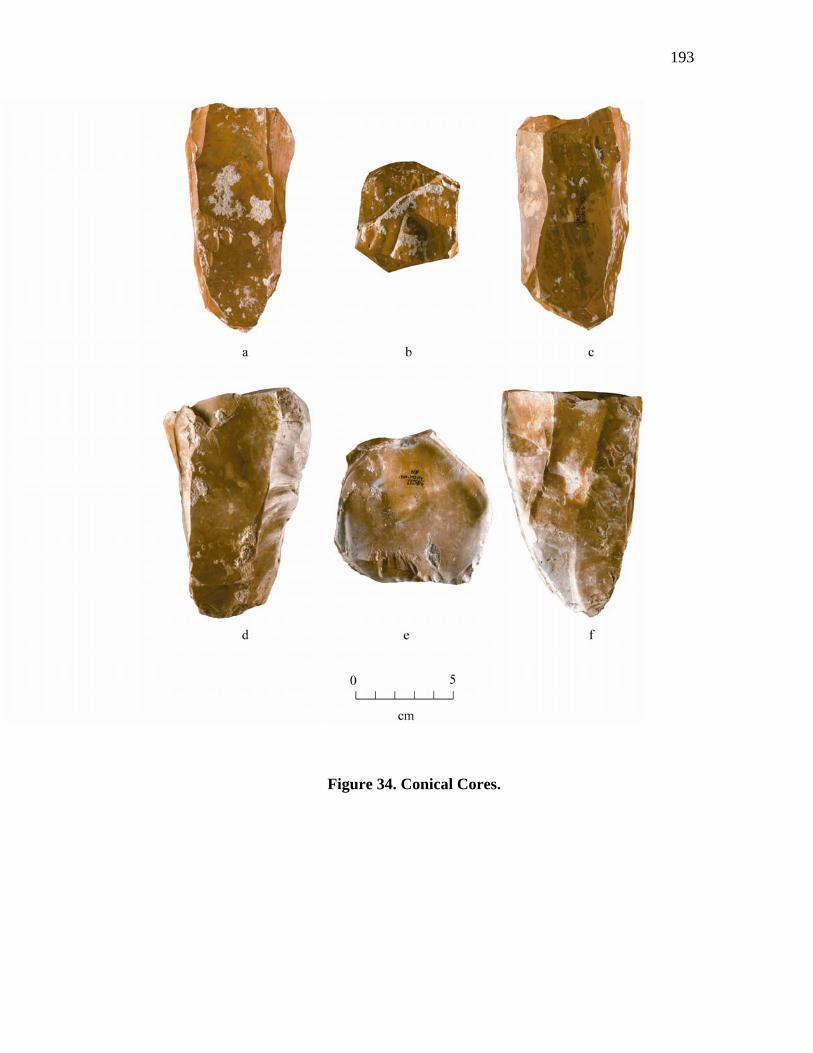
193
Figure 34. Conical Cores.
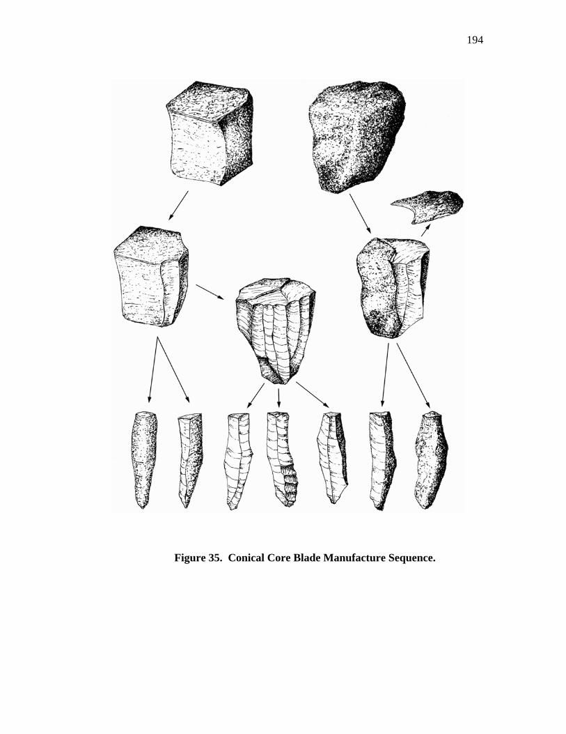
194
Figure 35. Conical Core Blade Manufacture Sequence.
195
removal is required. If no ridge or corner is present, or if one is present and it is not
adjacent to an adequate platform surface, the end or top of the cobble is removed to
serve as a platform surface. Once the surface is established, an initial blade could then
be removed. Typically, if the cobble's surface is too rounded or the lateral edges are not
prominent enough to facilitate additional blade removals, the lateral edges from the
first removal were flaked back forming a more prominent crest for fracture to follow.
However, because the cobbles at Gault originated from the surrounding slopes, most
still retain one or more corners or ridges that are suitable for initial removal without the
use of the cresting procedure.
Sizes range from 86.7 mm to 130.5 mm in length, 59.7 mm to 78.4 mm wide,
and 56.2 mm to 79.6 mm thick (Appendix A, Table 47). All have multiple bi-
directional blade scars with widths ranging between 28 mm and 46 mm. The entire
circumference on one specimen is completely flaked, while the other two still retain
varying amounts of cortex. The bi-directional flaking suggests that as platforms were
exhausted on the proximal end, the core was reversed and flaking commenced from
that (distal) end.
This type flaking has been described as producing flatter blades as opposed to
those that bend (Bordes and Crabtree 1969:2). For example, a core face on a conical
core illustrated from the Green cache (Green 1963:161) was described by Bordes and
Crabtree (1969:10) as having uni-directional blade scars that appear to have produced
flat blades with feathered terminations. A close examination of the illustration reveals
that there has been some flaking from the distal end, as well as at least one scar flaked
196
in a lateral direction. These may be core maintenance flakes, but they may have also
served to reduce curvature.
Recently, a Clovis conical core was reported from Victoria County
(Birmingham and Bluhm 2003:55-58). It is described as being 182 mm long and 70mm
across the platform with 11 primary blade facets flaked in a uni-directional direction. In
addition to the primary blade facets, there has been some lesser flaking from the distal
end which is interpreted as having been performed to straighten the core face, to
remove hinges from failed blade removals, and/or to reduce curvature of the blades
removed. The illustration of this core shows the blade facets to be relatively flat with
little curvature.
The Victoria County core and the core from the Green Cache indicate that some
Clovis core faces were modified to maintain or create flatter surfaces, indicating that
blades having little or no curvature were intentionally produced. Two of the Gault
conical cores have blade scars that are flat, but additional scars on one of these cores
also bend medially, while the third core (Specimen Number 793) contains only scars
that bend.
The platform ends of two specimens (Figure 34) have had their dorsal surfaces
completely flaked by a single flake (core tablet) removal. The distal end on one
specimen also has had its distal end flaked in a radial pattern that includes several small
blade removals along the margin. The platform end on the third core has multiple bi-
directional flake removals, with several terminating in hinge and step type
terminations. The negative bulb scar of one of these flakes is deeply concave with this
197
concavity centered between two adjacent platforms, from which, each have had a blade
struck.
All of these specimens contain a number of flake removals flaked in both lateral
and perpendicular directions. This flaking was performed to remove problems, re-
establish satisfactory ridges, and/or a good flaking surface. One specimen is heavily
cracked and more blocky than the other two and, as evidenced by the small blade scars
on the margin of the distal end, may have had its flake direction changed to circumvent
the cracks. Material flaws, such as cracks and inclusions, were the probable reasons for
the abandonment of cores (specimens 804 and 823). In addition, the distal end on one
core (Figure 34 d-f) is heavily battered, suggesting a final use as a possible chopping
tool.
Wedge-Shaped Cores (N = 31, Figures 36, 37, 38, and 39)
These cores differ from the conical type by having a more acute angle between
the platform and the blade surface, are generally narrower, being made on more slab-
like tabs than the blocky forms used for conical cores, and having multi-faceted
platforms (Collins 1999a:51). The Gault cores fit well within this definition, but with
the larger number of specimens within the assemblage, a greater range of variability
became evident.
Material selected for these cores was almost exclusively rectangular to blocky
tabs of chert found on the slopes surrounding Gault. In some rare cases, cobbles from
the creek were also utilized. Initial flaking of the core began along one of the narrow
ends having, either a natural or prepared corner with an angle around 90° or slightly
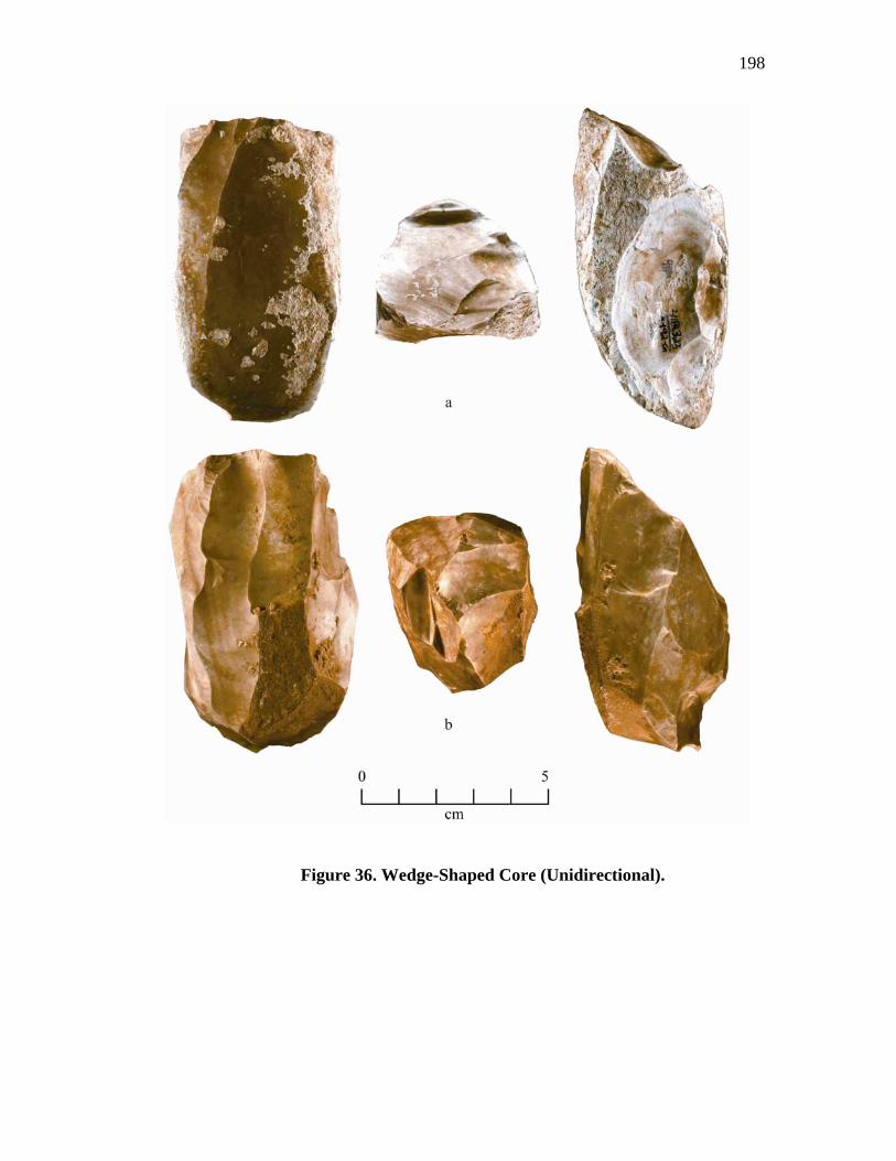
198
Figure 36. Wedge-Shaped Core (Unidirectional).
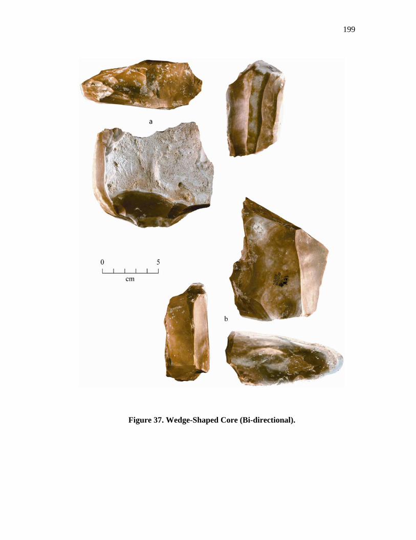
199
Figure 37. Wedge-Shaped Core (Bi-directional).
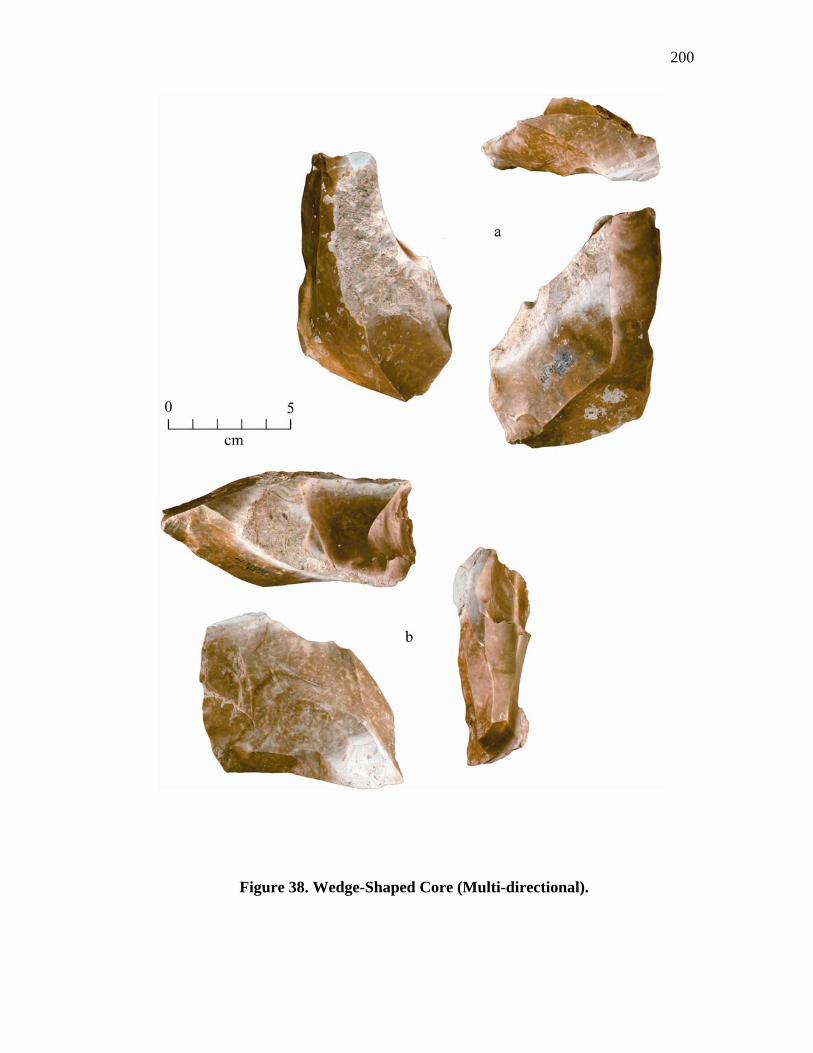
200
Figure 38. Wedge-Shaped Core (Multi-directional).
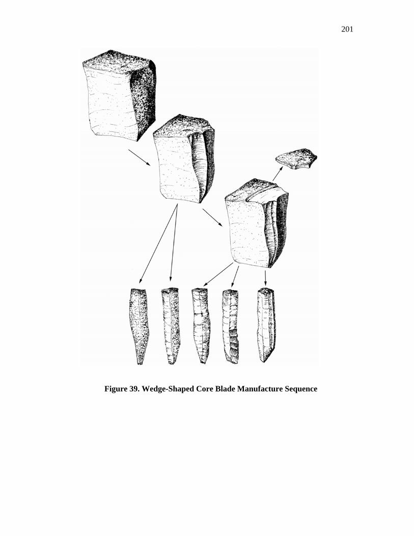
201
Figure 39. Wedge-Shaped Core Blade Manufacture Sequence
202
. less. The first removals would remove the cortex and establish ridges for subsequent
blade production. Once the cortex was removed, the next sequence of removals could
commence. Blades removed from this sequence, and all others that followed would
include both secondary and interior types (Figure 39).
Blades were flaked in a series around the core's end until the usable platform
surface was exhausted. Each removal not only reduced the platform surface, but (as
each blade was removed) the negative bulb caused a slight concavity to form
immediately below the platform edge. This edge could be removed by flaking down
the core’s longitudinal surface, grinding back or down, or flaking back onto the
platform surface. These procedures eventually resulted in an edge angle that was
unsuitable for a successful blade removal. This situation and the reduced platform
surface from previous removals necessitated the re-forming of a new platform surface
by flaking the dorsal surface back from the edge. This flaking often angled or plunged
into the tabs surface forming a slight acute angle, while on many of the more exhausted
cores, the entire dorsal surface had been totally flaked by a single blade-like flake.
The repeated flaking back from the cores edge or side often created a platform
edge that was very acute or sharp. Not only was the striking angle too steep, but also
the edge was so thin and weak that it would crush upon impact. A suitable striking
angle and strengthening of the platform edge was easily adjusted by simple abrasion or
minor flaking back from the edge. The abrasion of these edges and/or corners
strengthens and re-aligns the platform angle. This preparation often created a platform
surface composed of many small microflake scars or facets. In some cases flaking of
203
the platform surface produced a very deep central concavity with the lateral edges of
this concavity flaring up onto one or more of the tabs corners. This flaring up onto or
near one of the corners formed a well defined projection that was also easily modified
into a well isolated platform by the same procedure of minor abrasion and/or pressure
flaking.
Not all blade removals were successful. Many hinged or broke prematurely
hindering additional removals. These problems may or may not have been corrected by
flaking from either the distal end or one of the sides. In addition, material flaws, such
as inclusions and cracks, also create flaking problems. As a result of some of these
issues, the flaking direction was often changed in attempts to avoid these problems.
Therefore, as a core was reduced, blade flaking may occur on either end, over one or
more sides, or laterally across the dorsal or ventral edges. Thus, wedge-shaped cores
will have flake scar patterns that include uni-directional, bi-directional, or multi-
directional patterns, as well as surfaces having a number of overlapping flake scars,
some with hinge or step terminations.
Thirteen of the Gault wedge-shaped cores have uni-directional scar patterns
(Figure 36), 12 are bi-directional (Figure 37), and 6 are multi-directional (Figure 38)
(Appendix A, tables 48-50). Most of the uni-directional cores (N = 8) have blade facets
on one end, 1 is flaked on both ends, 3 are flaked on both the sides and an end, and 1 is
flaked only on one side. Blade facets average three per end with platforms ranging
between 64° and 87° (Appendix A, Table 48). Seven of the uni-directional cores have
204
blade facets that are flat, but five of these also contain blade facets that bend either
medially or distally. The remaining cores only have bending type blade facets.
The majority (N = 5) of the bi-directional cores have blade facets on two ends
and one or more sides, while the remaining cores (represented by one each) have blade
facets on two ends, one side, or one side and the basal edge. Specimen (806), flaked on
only one side, has blade facets that contain a number of material flaws and
irregularities and have had a number of small flake (non-blade) removals that seem to
have been attempts at finding enough "clear" material. This flaking failed to uncover
enough good material for blade flaking and the core abandoned. The number of blade
facets on these cores, increases to an average of six with remaining platform angles
ranging between 63° and 89° (Appendix A, Table 49). Flat blade facets are present on
all cores except one, but all the cores with flat facets also have facets that bend
medially or distally.
The blade facets found on the multi-directional cores vary widely with flaking
occurring randomly on both ends, sides, and either the dorsal or ventral edges. The
highest number of blade facets (N = 9), were found on the multi-directional cores but
have an overall average of 6, the same as on bi-directional cores. The platform angles
remain high ranging between 67° and 92°, but most fall within the 78° to 84° range
(Appendix A, Table 50). All of the cores, except one, contain flat blade facets, as well
as facets that bend medially and/or distally.
The sizes of wedge-shaped cores, whatever the scar pattern, vary widely. This
is not unexpected as many of these cores were abandoned only after a few blade
205
removals while others were extensively flaked. Sizes range between 55.5 mm and
124.1 mm in length with an average of 91.5 mm, widths range 47.3 mm and 99.2 mm
with an average of 69.0 mm, and thickness range 30.4mm and 78.8 mm with an
average of 44.9 mm.
Other Cores (N = 12)
This category is made up of a group of miscellaneous irregular cores and core
fragments that do not fit the descriptions for either of the previous types. Due to the
fragmentary shape of some of these specimens, a few of these may actually be
fragments of early stage bifaces, cores resulting from flake production, or practice
pieces and not true blade cores. The idea of some being biface fragments is a distinct
possibility since blades and blade-like flakes were also removed during early bifacing.
In addition, the site is a quarry workshop and practice knapping would have been
included in some of the activities conducted during its occupation, which could account
for some of the irregular specimens. However, placement in this category was based on
the predominant number and placement of existing blade or blade-like scars.
This group includes 6 core fragments, 2 core clean-up flakes, and 4 tested cobbles. The
core fragments consist of 1 lateral, 1 distal, and 4 unknown fragments. It is difficult to
say with any certainty what type of cores these fragments originated from. Any blade
scars present are remnants only, and much of the remaining surfaces on these
fragments have been flaked over by small core maintenance and/or recovery flaking.
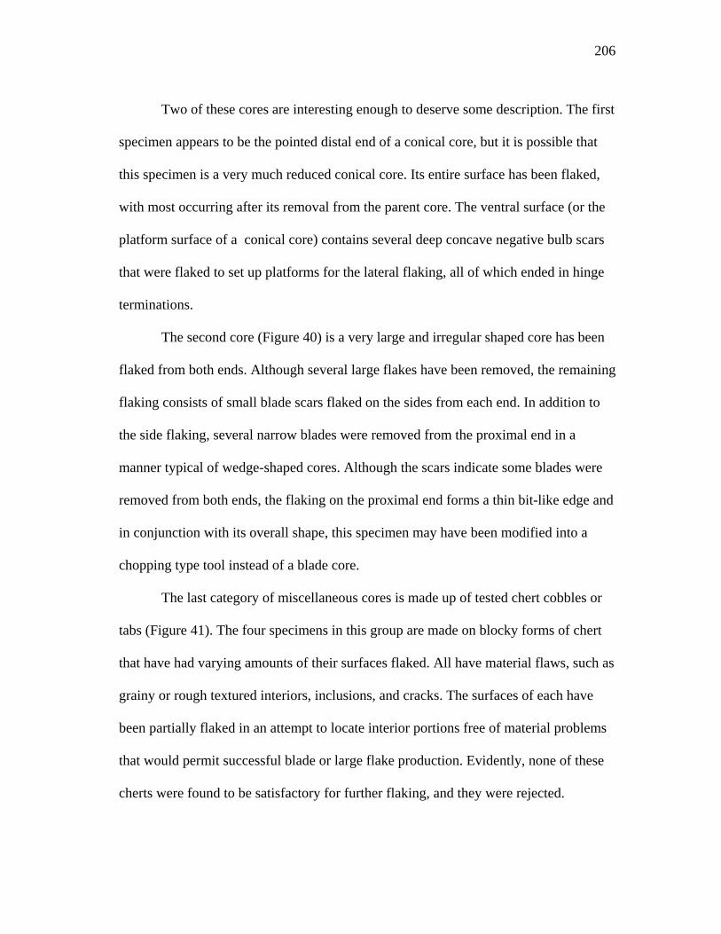
206
Two of these cores are interesting enough to deserve some description. The first
specimen appears to be the pointed distal end of a conical core, but it is possible that
this specimen is a very much reduced conical core. Its entire surface has been flaked,
with most occurring after its removal from the parent core. The ventral surface (or the
platform surface of a conical core) contains several deep concave negative bulb scars
that were flaked to set up platforms for the lateral flaking, all of which ended in hinge
terminations.
The second core (Figure 40) is a very large and irregular shaped core has been
flaked from both ends. Although several large flakes have been removed, the remaining
flaking consists of small blade scars flaked on the sides from each end. In addition to
the side flaking, several narrow blades were removed from the proximal end in a
manner typical of wedge-shaped cores. Although the scars indicate some blades were
removed from both ends, the flaking on the proximal end forms a thin bit-like edge and
in conjunction with its overall shape, this specimen may have been modified into a
chopping type tool instead of a blade core.
The last category of miscellaneous cores is made up of tested chert cobbles or
tabs (Figure 41). The four specimens in this group are made on blocky forms of chert
that have had varying amounts of their surfaces flaked. All have material flaws, such as
grainy or rough textured interiors, inclusions, and cracks. The surfaces of each have
been partially flaked in an attempt to locate interior portions free of material problems
that would permit successful blade or large flake production. Evidently, none of these
cherts were found to be satisfactory for further flaking, and they were rejected.
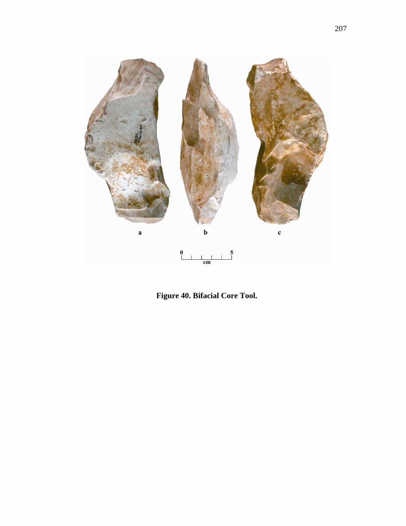
207
Figure 40. Bifacial Core Tool.
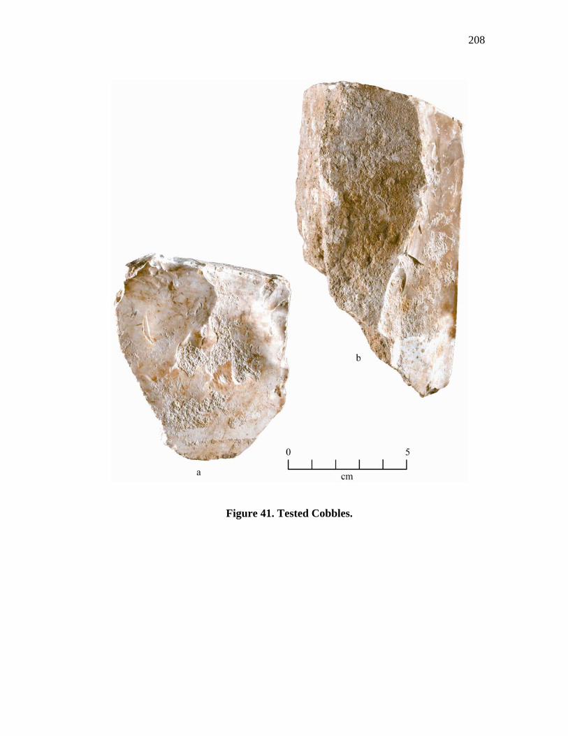
208
Figure 41. Tested Cobbles.
209
Platform Rejuvenation Techniques
Successful Clovis blade production was dependant upon establishing and
maintaining proper platforms and surfaces. As each sequence of blades was flaked, the
striking platforms for each blade was removed or damaged beyond re-use, resulting in
the need to be re-formed or adjusted. The following is a discussion of several of these
techniques.
Core Tablets (N = 42, Figure 42)
One of the primary rejuvenation techniques was to remove the entire top of the
core after all of the platforms were exhausted and to establish new platforms on a fresh
surface. The removed tops of these cores are a very recognizable flake form and are
called core tablets (Collins 1999a). These core tablets contain excellent records and
attributes of the exhausted platforms on their dorsal surfaces, which can provide
additional information on Clovis platform strategies.
The classic description for a core tablet is one that has removed the top of a
conical core. If successful, and the entire top of the core was removed (many are only
partial removals), the circumference of the tablet will retain the proximal portions of
several blade scars. The size of the tab and the exact number of blade scars will vary as
they are dependant upon how many blades have been removed from around the core's
circumference. The dorsal surface of these core tablets may have multiple deep
negative bulb scars around the periphery of the tab's edge, or a central knot formed by
the cumulative flaking of platform maintenance flakes that often hinge or step fracture
(Collins 1999a:51).
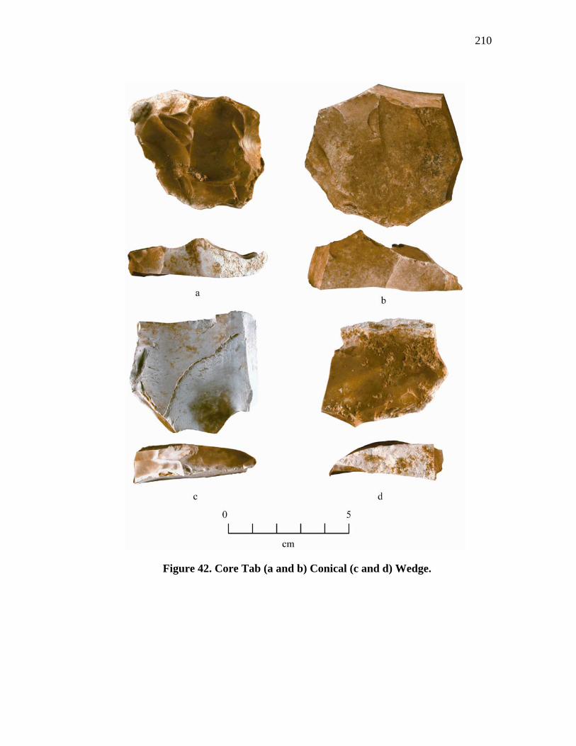
210
Figure 42. Core Tab (a and b) Conical (c and d) Wedge.
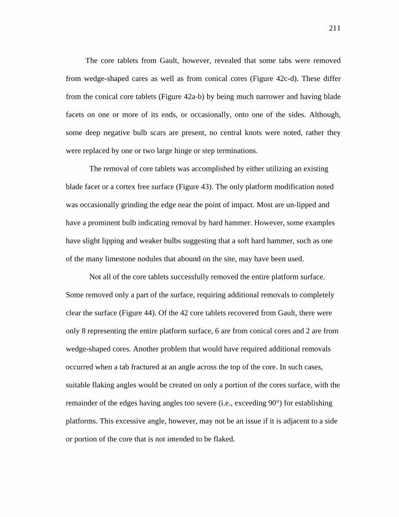
211
The core tablets from Gault, however, revealed that some tabs were removed
from wedge-shaped cares as well as from conical cores (Figure 42c-d). These differ
from the conical core tablets (Figure 42a-b) by being much narrower and having blade
facets on one or more of its ends, or occasionally, onto one of the sides. Although,
some deep negative bulb scars are present, no central knots were noted, rather they
were replaced by one or two large hinge or step terminations.
The removal of core tablets was accomplished by either utilizing an existing
blade facet or a cortex free surface (Figure 43). The only platform modification noted
was occasionally grinding the edge near the point of impact. Most are un-lipped and
have a prominent bulb indicating removal by hard hammer. However, some examples
have slight lipping and weaker bulbs suggesting that a soft hard hammer, such as one
of the many limestone nodules that abound on the site, may have been used.
Not all of the core tablets successfully removed the entire platform surface.
Some removed only a part of the surface, requiring additional removals to completely
clear the surface (Figure 44). Of the 42 core tablets recovered from Gault, there were
only 8 representing the entire platform surface, 6 are from conical cores and 2 are from
wedge-shaped cores. Another problem that would have required additional removals
occurred when a tab fractured at an angle across the top of the core. In such cases,
suitable flaking angles would be created on only a portion of the cores surface, with the
remainder of the edges having angles too severe (i.e., exceeding 90°) for establishing
platforms. This excessive angle, however, may not be an issue if it is adjacent to a side
or portion of the core that is not intended to be flaked.
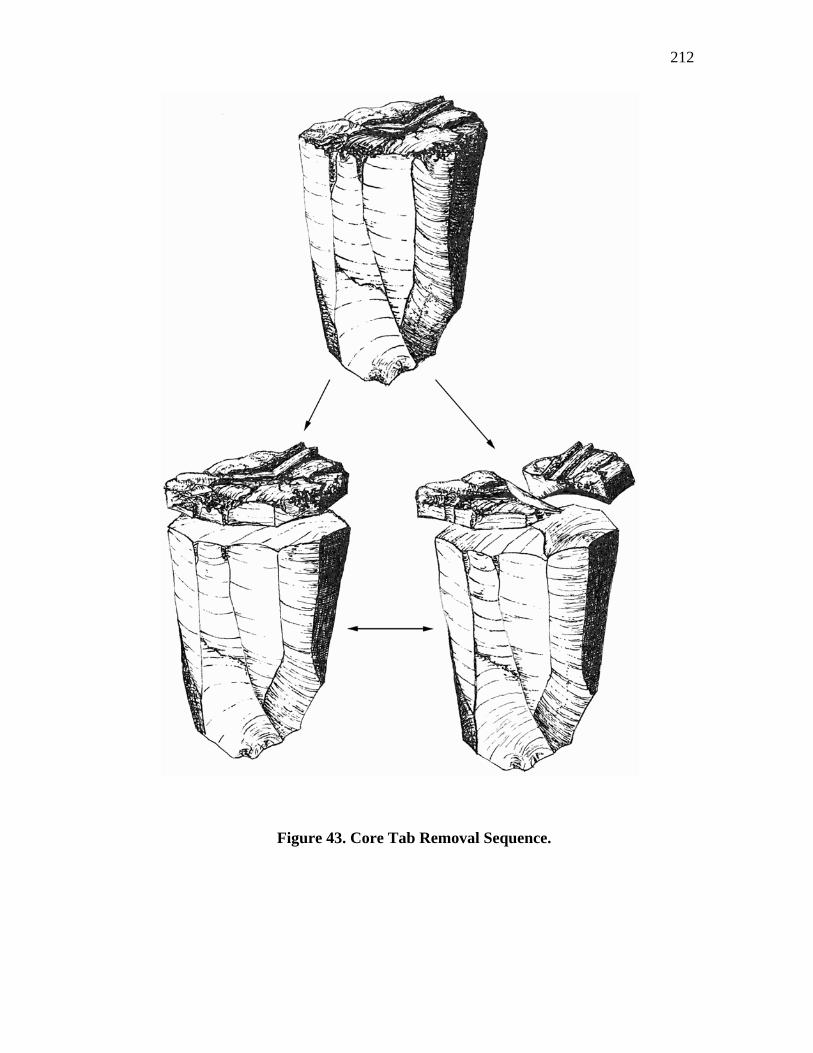
212
Figure 43. Core Tab Removal Sequence.
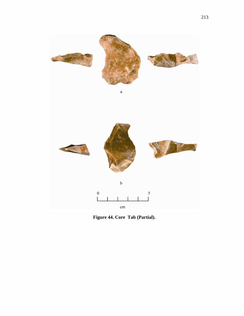
213
Figure 44. Core Tab (Partial).
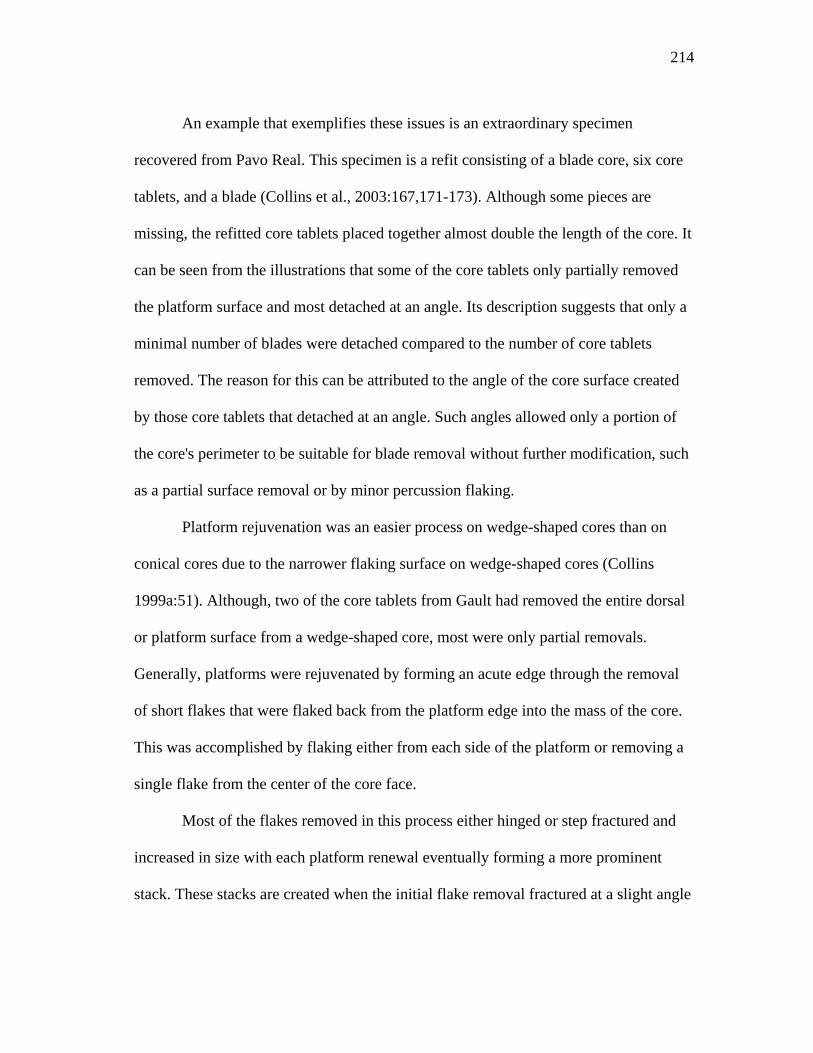
214
An example that exemplifies these issues is an extraordinary specimen
recovered from Pavo Real. This specimen is a refit consisting of a blade core, six core
tablets, and a blade (Collins et al., 2003:167,171-173). Although some pieces are
missing, the refitted core tablets placed together almost double the length of the core. It
can be seen from the illustrations that some of the core tablets only partially removed
the platform surface and most detached at an angle. Its description suggests that only a
minimal number of blades were detached compared to the number of core tablets
removed. The reason for this can be attributed to the angle of the core surface created
by those core tablets that detached at an angle. Such angles allowed only a portion of
the core's perimeter to be suitable for blade removal without further modification, such
as a partial surface removal or by minor percussion flaking.
Platform rejuvenation was an easier process on wedge-shaped cores than on
conical cores due to the narrower flaking surface on wedge-shaped cores (Collins
1999a:51). Although, two of the core tablets from Gault had removed the entire dorsal
or platform surface from a wedge-shaped core, most were only partial removals.
Generally, platforms were rejuvenated by forming an acute edge through the removal
of short flakes that were flaked back from the platform edge into the mass of the core.
This was accomplished by flaking either from each side of the platform or removing a
single flake from the center of the core face.
Most of the flakes removed in this process either hinged or step fractured and
increased in size with each platform renewal eventually forming a more prominent
stack. These stacks are created when the initial flake removal fractured at a slight angle
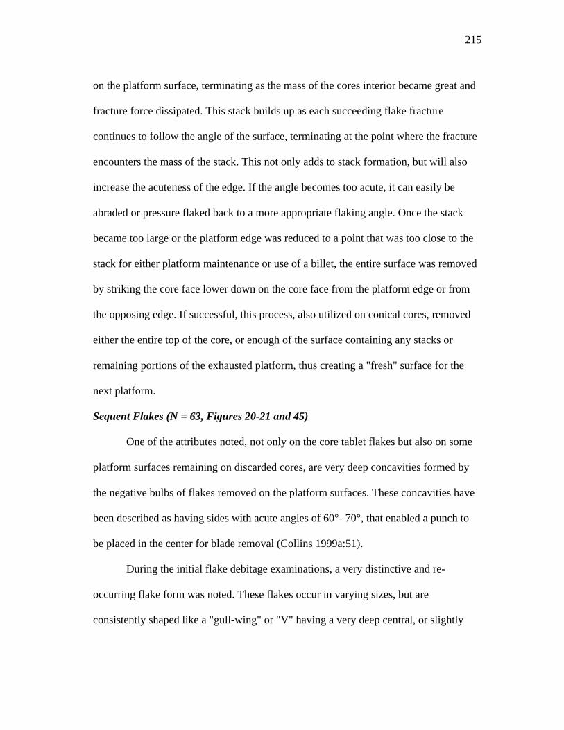
215
on the platform surface, terminating as the mass of the cores interior became great and
fracture force dissipated. This stack builds up as each succeeding flake fracture
continues to follow the angle of the surface, terminating at the point where the fracture
encounters the mass of the stack. This not only adds to stack formation, but will also
increase the acuteness of the edge. If the angle becomes too acute, it can easily be
abraded or pressure flaked back to a more appropriate flaking angle. Once the stack
became too large or the platform edge was reduced to a point that was too close to the
stack for either platform maintenance or use of a billet, the entire surface was removed
by striking the core face lower down on the core face from the platform edge or from
the opposing edge. If successful, this process, also utilized on conical cores, removed
either the entire top of the core, or enough of the surface containing any stacks or
remaining portions of the exhausted platform, thus creating a "fresh" surface for the
next platform.
Sequent Flakes (N = 63, Figures 20-21 and 45)
One of the attributes noted, not only on the core tablet flakes but also on some
platform surfaces remaining on discarded cores, are very deep concavities formed by
the negative bulbs of flakes removed on the platform surfaces. These concavities have
been described as having sides with acute angles of 60°- 70°, that enabled a punch to
be placed in the center for blade removal (Collins 1999a:51).
During the initial flake debitage examinations, a very distinctive and re-
occurring flake form was noted. These flakes occur in varying sizes, but are
consistently shaped like a "gull-wing" or "V" having a very deep central, or slightly
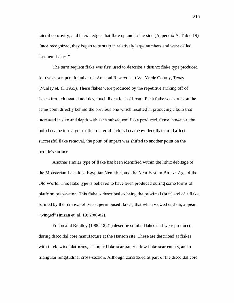
216
lateral concavity, and lateral edges that flare up and to the side (Appendix A, Table 19).
Once recognized, they began to turn up in relatively large numbers and were called
"sequent flakes.”
The term sequent flake was first used to describe a distinct flake type produced
for use as scrapers found at the Amistad Reservoir in Val Verde County, Texas
(Nunley et. al. 1965). These flakes were produced by the repetitive striking off of
flakes from elongated nodules, much like a loaf of bread. Each flake was struck at the
same point directly behind the previous one which resulted in producing a bulb that
increased in size and depth with each subsequent flake produced. Once, however, the
bulb became too large or other material factors became evident that could affect
successful flake removal, the point of impact was shifted to another point on the
nodule's surface.
Another similar type of flake has been identified within the lithic debitage of
the Mousterian Levallois, Egyptian Neolithic, and the Near Eastern Bronze Age of the
Old World. This flake type is believed to have been produced during some forms of
platform preparation. This flake is described as being the proximal (butt) end of a flake,
formed by the removal of two superimposed flakes, that when viewed end-on, appears
"winged" (Inizan et. al. 1992:80-82).
Frison and Bradley (1980:18,21) describe similar flakes that were produced
during discoidal core manufacture at the Hanson site. These are described as flakes
with thick, wide platforms, a simple flake scar pattern, low flake scar counts, and a
triangular longitudinal cross-section. Although considered as part of the discoidal core
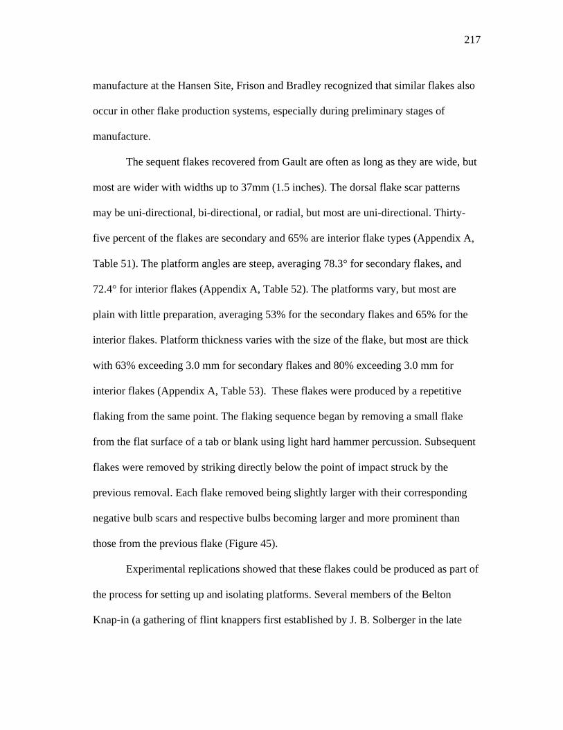
217
manufacture at the Hansen Site, Frison and Bradley recognized that similar flakes also
occur in other flake production systems, especially during preliminary stages of
manufacture.
The sequent flakes recovered from Gault are often as long as they are wide, but
most are wider with widths up to 37mm (1.5 inches). The dorsal flake scar patterns
may be uni-directional, bi-directional, or radial, but most are uni-directional. Thirty-
five percent of the flakes are secondary and 65% are interior flake types (Appendix A,
Table 51). The platform angles are steep, averaging 78.3° for secondary flakes, and
72.4° for interior flakes (Appendix A, Table 52). The platforms vary, but most are
plain with little preparation, averaging 53% for the secondary flakes and 65% for the
interior flakes. Platform thickness varies with the size of the flake, but most are thick
with 63% exceeding 3.0 mm for secondary flakes and 80% exceeding 3.0 mm for
interior flakes (Appendix A, Table 53). These flakes were produced by a repetitive
flaking from the same point. The flaking sequence began by removing a small flake
from the flat surface of a tab or blank using light hard hammer percussion. Subsequent
flakes were removed by striking directly below the point of impact struck by the
previous removal. Each flake removed being slightly larger with their corresponding
negative bulb scars and respective bulbs becoming larger and more prominent than
those from the previous flake (Figure 45).
Experimental replications showed that these flakes could be produced as part of
the process for setting up and isolating platforms. Several members of the Belton
Knap-in (a gathering of flint knappers first established by J. B. Solberger in the late
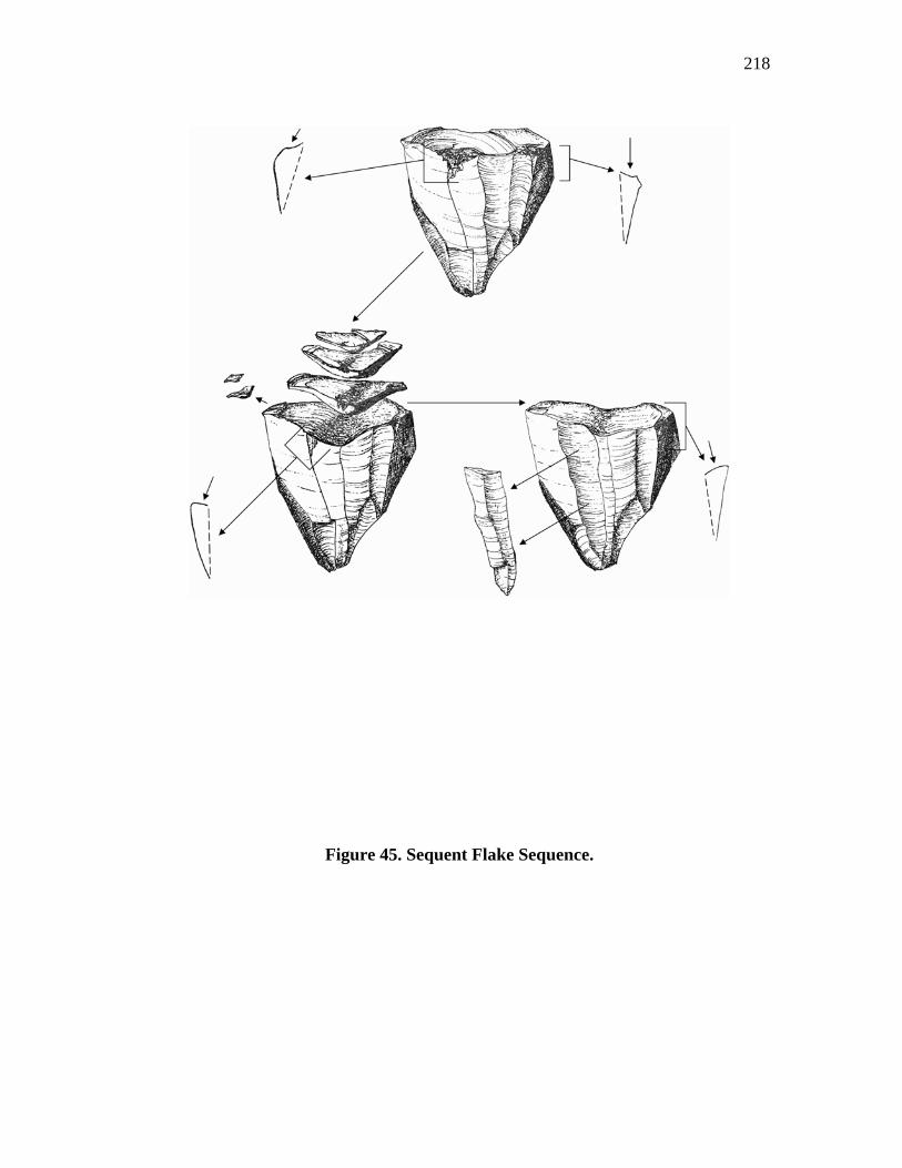
218
Figure 45. Sequent Flake Sequence.
219
1960's) were asked to use this method during bifacial thinning. The result was that the
platforms produced were prominently isolated which enabled large flakes, many
terminating near or over the opposite edge to be easily removed. In addition, platforms
on blade cores were set up using this method and were found to be very effective.
These results suggested that this may be a suitable method in both biface and blade
core preparation. As noted previously (with each flake produced) the resulting scars
produced are larger and have deeper more prominent negative bulbs. When two widely
spaced sets of these flakes are removed, a prominent and isolated "hump" is formed
between them.
With careful execution, these humps can be formed directly over an existing
ridge or corner on the core face, requiring little modification to form them into a raised
and well-isolated platform (Figure 45). A single set may only be necessary if the
platform surface already contains some undulations or concavities, or if the width of
the platform surface is narrow, such as on wedge-shaped cores. A drawback could
occur if the sets are too close together, or if too many flakes were removed which
would begin to overflake and decrease the height of the hump. The dorsal surface of
these humps are often very acute, angling back into the blank's mass with edges that
are sharp. This condition is easily corrected by minor flaking of the edge, which will
strengthen the edge and alter the promontory to a desired striking angle.
Because evidence for this type of platform preparation would be removed
during bifacial edge trimming or additional platforming, no evidence was noted on any
of the bifaces. However, the presence of the deep scars on the core tablets and platform
220
surfaces of some of the cores, suggests that this method was commonly used in blade
core platform preparation.
Refits
Blade and Blade Core Re-Fits (N = 3, Figures 46, 47, and 48)
One of the studies conducted on the artifacts and lithic debitage was to attempt
to retrofit together any broken flakes, blades, or core fragments. The successful re-
fitting of pieces together, such as broken projectile points, bifaces, and superimposed
blades can be an important aid in determining a number of technological aspects, such
as reasons for failure, flaking sequences, and platform rejuvenation techniques. Within
the Gault assemblage, a number of refits were successful, but only 2 sets of
superimposed blades and 1 core are considered here.
Refit 1
This refit (Figure 46) consists of a single blade (Specimen 953) that was
superimposed over a larger blade-flake (Specimen 954). The distal end of both of these
flakes contains the heavy white patina noted on the ends and sides of many of Gault's
chert tabs. In addition, one lateral edge on the blade and both lateral edges on the
blade-flake retain the thick, chalky type of natural cortex typically present only on the
chert's dorsal and ventral surfaces.
The blade measures 89.6 mm long, 39.4 mm wide, and 14.4 mm thick. It has a
7.8 index of curvature and a width to length ratio of 2.28. The blade-flake measures
113.4 mm long, 54.0 mm wide, and 20.8 mm thick, with a 7.9 index of curvature and a
2.1 width to length ratio. Both platforms are natural, the blade having a platform that is
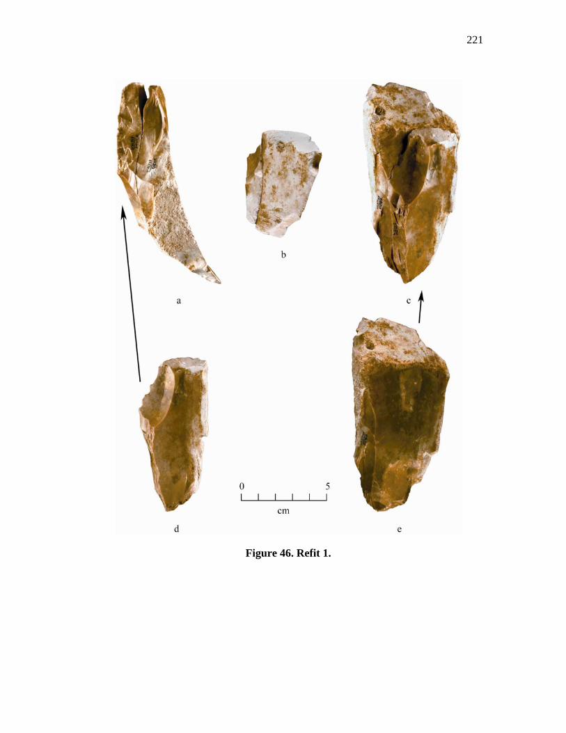
221
Figure 46. Refit 1.
222
9.4 mm wide by 3.1 mm thick with a platform angle of 70°. The platform on the blade-
flake measures 12.5 mm wide and 6.3 mm thick with a platform angle of 83°. The
platforms on both flakes have been isolated and ground, however, the grinding on the
blade-flake is slight.
Aligning this refit into its approximate position at the time of removal shows
that they were struck off at a very acute angle and from the narrow end of a tab,
indicating their probable removal from a wedge-shaped core. The dorsal surface on the
blade contains an earlier blade removal scar. Evidently, after the earlier blade was
removed, the more central positioned ridge was straightened by the partially cresting of
the proximal half of the ridge before the platform was isolated and ground. The lack of
a lip and a large bulb of percussion on its ventral surface indicate removal via hard
hammer percussion.
Once the blade was struck off, the platform on the blade-flake was isolated and
slightly ground. Like the blade, the platform on the blade-flake is natural, indicating no
special attempt at establishing a flaking angle or surface occurred. As no material flaws
or knapping problems are present, it is not exactly clear whether a blade was the intent
of this removal or if the removal of the entire end of the tab was intended. It has been
observed, however, that during experimental blade replications, the ends of narrow tabs
were frequently removed unintentionally by plunging type fractures, either by striking
too far into the core's mass and/or applying too much force. This suggests that the
blade-flake's removal of the tab's entire end may have been unintentional.
223
Refit 2
This refit (Figure 47) consists of two superimposed blades (specimens 951 and
952). The distal ends of both of these blades are partially covered with a heavy white
patina, otherwise they are cortex free. The uppermost blade (specimen 951) measures
86.0 mm long, 34.7 mm wide, and 18.2 mm thick, has a 14.1 index of curvature and
2.47 width to length ratio. The lower blade (specimen 952) measures 87.3 mm long,
42.0 mm wide, and 23.4 mm thick, has a 8.3 index of curvature, and a 3.73 width to
length ratio. The platform on Specimen Number 951 (blade) is plain, measuring 10.7
mm wide and 5.7 mm thick with an approximate platform angle of 76° and has been
isolated and ground. The platform on Specimen Number 952 (blade) has been crushed
with an approximate width of 18.5 mm and 5.2 mm thick. Its platform angle cannot be
determined due the crushing damage, but it has been isolated and ground. No platform
lipping is present on either blade, but the bulbs of percussion on both are diffuse.
Positioning the blades together and aligning them to their position at the time of
removal shows that they were struck off at a very acute angle from a narrow wedge-
shaped core. Prior to the removal of Blade 951 from Blade 952, both of the lateral sides
on both of the blades had been flaked at 90° to the direction of their final removals.
Blade 951 was detached at an angle across and over Blade 952 creating the extreme
curvature of 14.1. After its removal, the central portion of the primary ridge on Blade
952 was straightened by cresting.
The lateral flaking noted on the sides of these blades indicates that the flaking
direction on their parent core was altered to a multi-directional pattern. The lateral
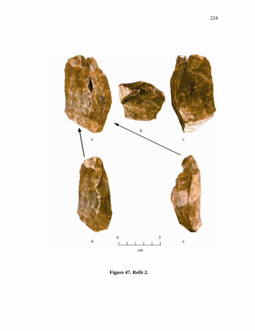
224
Figure 47. Refit 2.
225
flake scars are not core preparation or re-facing removals as they are wide and typical
of blade type flaking with no apparent problems noted. It cannot be determined if
flaking occurred on both ends, but it does appear that initial flaking began on one end,
then was switched to the lateral sides before flaking was again changed back to the first
end.
Refit 3
This refit consists of three blade-flakes superimposed onto a blocky core
fragment (Figure 48). The three blade-flakes (specimens 956, 957, and 958) are all flat
irregular shaped flakes with the platform ends covered in a heavy white patina and
onelateral edge (on each) covered in a thick chalky type cortex. The core fragment has
a white patina on two of its sides and the chalky cortex on only on side.
The flakes range 56.4 mm - 70.6 mm in length, 34.6 mm - 40.1 mm wide, and
11.2 mm - 15.2 mm thick, with the core fragment measuring 84.8 mm long, 56.7 mm
wide, and 39.8 mm thick. Additional flakes had been removed, but these were not
found. The platform angles range between 64° and 71° and consist only of the natural
patinated surface of the core with no additional modification performed. None of the
flakes would have been suitable for use as tools as they are all irregular with some
containing cracks. The core fragment also contains a number of pressure cracks as well
as several hinged terminations. It is probable that the cores reduction was an attempt at
testing the internal quality of the core, which was found unacceptable, and all were
discarded. Since the site is located at a quarry, this core may, alternately, have served
as a practice piece for an inexperienced knapper. After all, it is more practical to
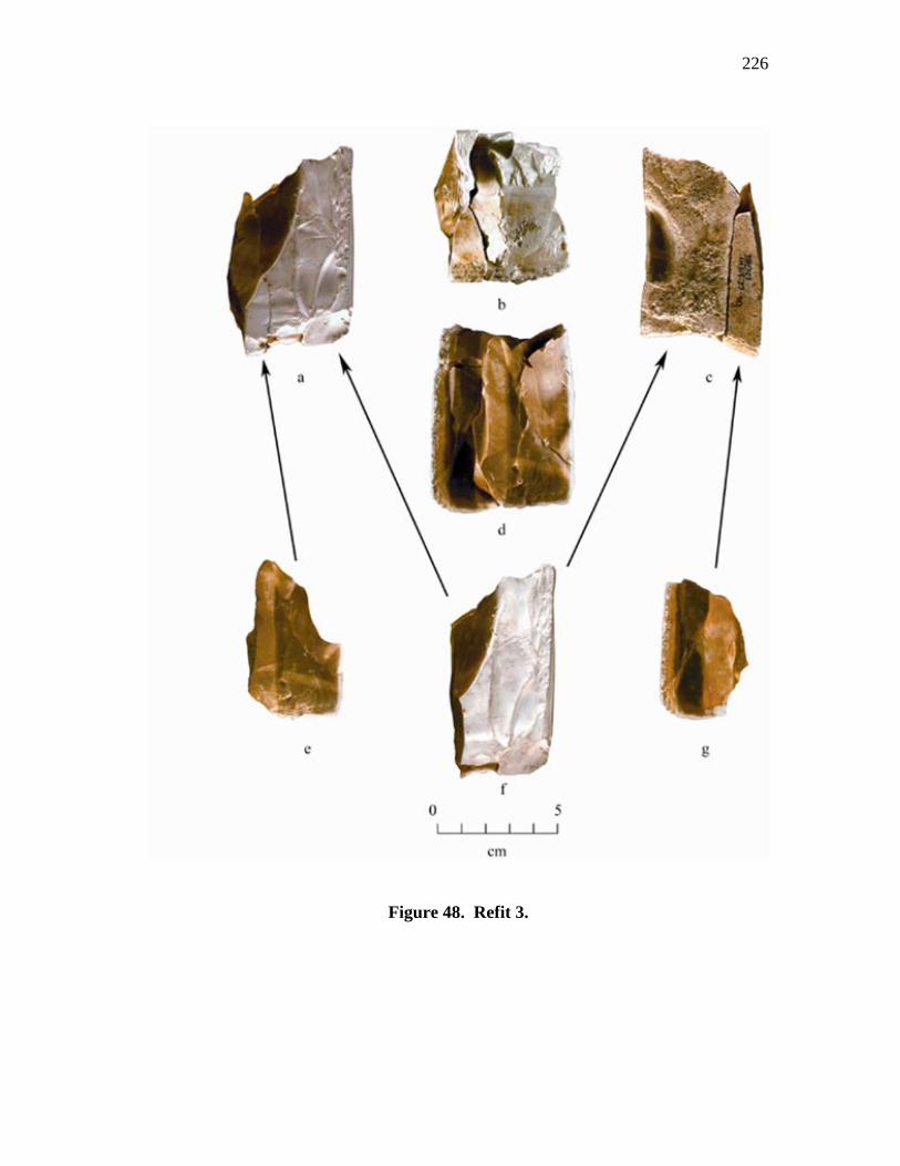
226
Figure 48. Refit 3.
227
practice knapping at a site containing abundant lithic resources than in regions where
they are scarce.
The analysis of these refits provides us with several interesting insights into
Clovis blade technology. First, it substantiates that the flake direction on wedge-shaped
cores was altered from either a uni-directional or bi-directional flaking of one or more
ends to a multidirectional flaking of all sides. As indicted previously in the core
analysis, reasons for the change in direction may include material flaws, uncorrectable
knapping errors, or re-platforming problems. However, once the flaking direction was
changed, and the core further reduced, surface conditions or platform re-forming
possibilities may have changed, making it possible to switch back to flaking from the
original, more suitable, surface.
The second, and most interesting, revelation from the refits is the continued use
of cresting in straightening or establishing prominent ridges. Previously, the technique
of cresting or forming a crested blade or lame à crête has been described as being
performed primarily during initial blade core preparation in which a bifacial ridge is
formed for the first blade removal (Bordes and Crabtree 1969; Crabtree 1972;
Whittaker 1994; Collins 1999a). However, both of the blade re-fits show that the
Gault's Clovis knappers used the cresting strategy, not only during initial blade core
preparation, but throughout the entire blade production sequence as well.
Geologic Placement
The primary geological units (Appendix A, Table 1; Figure 1) at Gault from
which the Clovis lithic materials were recovered are defined as Clovis clay (Geologic
228
Unit 3a) and Clovis soil (Geologic Unit 3b). Two gravel units, Geologic Unit 1 and
Geologic Unit 2, underlie the Clovis clay. Geologic Unit 1, the oldest colluvium, is
composed of a limestone gravel that originated from the surrounding slopes, and
Geologic Unit 2 is composed of a cherty gravel alluvium from Buttermilk Creek. The
Clovis soil does not come into contact with Geologic Unit 2 gravels, but does contact
some Geologic Unit 1 gravels near the base of the slope. Capping the Clovis soil is a
thick deposit (Geologic Unit 4b) that contains late Paleoindian projectile forms such as
Folsom and Midland types.
The Geologic Unit 1 limestone gravels accumulated at the base of the
surrounding slope forming a narrow bar that gradually pinches into the Geologic Unit 2
cherty gravels which, in turn, is bordered by Buttermilk Creek. Between the Geologic
Unit 1 and Geologic Unit 2 gravels is a slight depression in which a small pond
formed. The sediments deposited within this pond formed the Clovis clay (Geologic
Unit 3a) and the whole was eventually covered over by overbank (floodplain) deposits
from Buttermilk Creek which became the Clovis soil (Geologic Unit 3b). The Clovis
soil deposit was in turn covered over by soil, classified as Geologic Unit 4b, that
eroded from the slopes.
Table 1 (Appendix A) provides a listing of the number of blade types, cores,
core tablets, and wing flakes recovered from each of the individual geologic units.
While in the field, it was sometimes difficult to distinguish the two units in horizontal
with the vertical position. Therefore, if it was later determined that a level from an
229
excavation unit contained a mix of two different geological units, the geological
designation for that level was given as geologic units 3a or 3b.
Artifacts were occasionally recovered on the surface of the gravels (at the base
of the Clovis clay), but were found not to penetrate them. It is believed that artifacts
accumulated on these surfaces as a result of the Clovis folks sitting on the surface of
these gravels while performing knapping or subsistence activities. As such, any units
containing levels composed of Clovis Clay and gravels were condensed into a single
unit (Geologic Unit 3a).
The artifact counts show that approximately twice the number (or better) of
most of the lithic artifacts occur within the Clovis clay unit (Geologic Unit 3a) than
were recovered from within the Clovis soil unit (Geologic Unit 3b). The major
differences in this count occur within the crested blades, cores, and core tablets. The
number of crested blades and core tablets are almost equal between the units and
wedge-shaped cores have a ratio of 3 to 4 between the Clovis soil and Clovis clay.
Only two conical cores were recovered from the 3a and one from mixed geologic units
3a or 3b.
These counts suggest that blade manufacture from conical cores may have been
more prevalent in Geologic Unit 3a than Geologic Unit 3b. This assumption is
substantiated by the fact that the numbers of blades (all types) are approximately twice
the number in Geologic Unit 3a than in Geologic Unit 3b. As opposed to conical cores,
that utilize more squared, blocky or rounded cobbles, larger rectangular tabs of chert
can be used for wedge-shaped cores. This difference in material form would easily
230
allow for larger numbers of blades, especially secondary and corner removal types, to
be produced. However, if interior blades are the more preferred type, fewer may be
produced from wedge-shaped cores than conical cores, and many of the blades, may
represent rejections or, more simply, are waste flakes. Therefore, the larger number of
blades in Geologic Unit 3a may reflect a more prevalent use of wedge-shaped cores
over the conical type.
Aside from the increase in blades in Geologic Unit 3a, no technological
differences in blade production are apparent. Platforming strategies utilizing core
tablets and wing flakes are prevalent in both units. Although core tablets are generally
considered as produced primarily from conical cores, it was found that some were also
produced during wedge-shaped core platform rejuvenation as well. Therefore, not all of
the core tablets can be assigned to a particular core type, and their presence within both
units can only be concluded that the practice of this strategy continued throughout both
units, regardless of the difference in the number of core types recovered.
Summary
This analysis has studied a large assemblage of Clovis blade manufacturing
debris consisting of 464 blades, 50 blade cores, 36 core tablets, and 63 specialized
platform preparation flakes (winged flakes). In addition, a small number of blades,
blade-flakes, and a core fragment were refitted together into three groups. The large
number of artifacts studied within this assemblage afforded an opportunity to study
Clovis technology that has not previously been available. The result of this study, not
231
only substantiated much of our current understanding of Clovis technology, but also
has added several new and interesting aspects as well.
Collins (1999a:63,178) describes Clovis blades as having small platforms that
may be wide but not deep, flat bulbs of percussion, minimal ripple marks on the ventral
surface giving a smooth appearance, are generally long (frequently exceeding 100
mm), and are curved in longitudinal section. However, this analysis has found that a
larger diversity in blade forms exists than is covered by this definition. For example,
the Gault blades analyzed include both regular and irregular forms, some broken or
rejected during manufacture, but many obviously suitable for tool use. The cross-
sections of these blades were found to vary from almost flat to prominently triangular
with edge angles ranging from acute to abrupt. They have single or multiple
longitudinal, or occasionally, lateral ridges, and longitudinal sections that may be
strongly curved or flat. Blade lengths are long with averages (for all types) that range
between 63 mm and 96 mm with platforms averaging 10.2 mm wide and 4.1 mm thick.
Platform angles are generally high with an average of 72.7° and platform preparations
that may be unprepared or heavily modified by isolation, grounding and faceting
(Appendix A, Table 54). The bulbs of percussion on many blades are flat or diffuse
(Appendix A, Table 55), but some also have moderate to strongly prominent bulbs with
ventral surfaces that may be smooth or contain varying amounts of ripples and waves.
These variations should not be surprising as the Gault site is a quarry workshop and
camp where a variety of lithic tools were manufactured. During the manufacturing
process numbers of rejected or failed pieces would accumulate, as well as large
232
amounts of waste debitage from reduction and core/blank preparation. It is also
apparent that as reduction/manufacture progressed, platform preparation changed from
unprepared platforming during initial core preparation to those that are more carefully
prepared as more "refined" products began to be produced (Appendix A, tables 54, 56).
For these reasons, many of the blades would not conform to the standard Clovis blade
definition.
It is apparent that the standard definition for Clovis blades was developed
primarily from blades recovered from caches or isolated finds that probably represent
the best blades produced that were intended for transport and use while away from
lithic sources. One could reasonably argue that these blades represent the true blade
form and that all others are merely marginal or unsuitable and rejected examples.
Undoubtedly, this supposition is true. However, even though the majority of the blades
left at the quarry site do not conform exactly to the current definition, many of these
were utilized as tools as the use-wear analysis conducted on them confirms (Lohse, et.
al. 2002). Therefore, the Clovis folks utilized a wide range of blade forms, at least in
proximity to lithic sources, not restricting use only to blades agreeing with the
established definition.
The most interesting finds stemming from this analysis center within the
manufacturing process. Although there are a number of excellent chert sources
occurring within a 20 to 30 kilometer radius of Gault, all the blades and blade cores
utilized at Gault (with a single exception), came from the surrounding slopes. The one
exception found within the blade assemblage is a fragmented regular interior blade that
233
is made of quartzite. Two forms of raw materials were utilized at Gault. The first are
chert cobbles from Geologic Unit 2 that originated as chert that weathered from the
slopes and, through alluvial action, washed into Buttermilk Creek. These cobbles are
moderately sized, commonly found approaching 10 inches in length, are rounded with
some angular portions, and are covered with a thin hard cortex. Experimental testing of
these gravels showed that many flake well, but that most are unsuitable for tool
manufacture due to interiors that are grainy and/or contain a number of inclusions.
Suitable material would be selected only after intensive "testing" of a number of the
individual cobbles to determine which ones would be knappable. Cobble use, however,
was minimal, being confirmed on only a few examples.
The other form, used for the majority of the blade manufacture, were abundant
square sided, blocky chert tabs that eroded from the surrounding slopes. Not all of
these chert tabs have interiors that are knappable, many having interiors that vary in
color and are grainy with inclusions. It is evident that these compose the source for the
grainy cobbles found within the Unit 2 gravels. The favored form is dark gray colored
chert, having a fine-grained, almost slick interior that flakes with ease. Although few of
the better forms of chert presently remain on the site, the fine grained form was
evidently in abundance at the time of Clovis (and later) occupation. Cores were
initially prepared in several ways. Cobbles, for example, usually have one or more ends
that are rounded and unsuitable for initial flaking without modification. Therefore, one
of the ends has to be removed in order to establish a platform from which flakes or
blades could be longitudinally flaked. The blocky chert tabs, however, usually contain
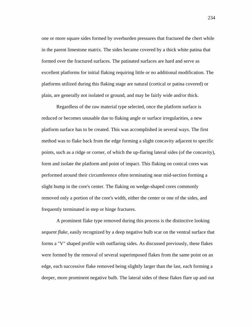
234
one or more square sides formed by overburden pressures that fractured the chert while
in the parent limestone matrix. The sides became covered by a thick white patina that
formed over the fractured surfaces. The patinated surfaces are hard and serve as
excellent platforms for initial flaking requiring little or no additional modification. The
platforms utilized during this flaking stage are natural (cortical or patina covered) or
plain, are generally not isolated or ground, and may be fairly wide and/or thick.
Regardless of the raw material type selected, once the platform surface is
reduced or becomes unusable due to flaking angle or surface irregularities, a new
platform surface has to be created. This was accomplished in several ways. The first
method was to flake back from the edge forming a slight concavity adjacent to specific
points, such as a ridge or corner, of which the up-flaring lateral sides (of the concavity),
form and isolate the platform and point of impact. This flaking on conical cores was
performed around their circumference often terminating near mid-section forming a
slight hump in the core's center. The flaking on wedge-shaped cores commonly
removed only a portion of the core's width, either the center or one of the sides, and
frequently terminated in step or hinge fractures.
A prominent flake type removed during this process is the distinctive looking
sequent flake, easily recognized by a deep negative bulb scar on the ventral surface that
forms a "V" shaped profile with outflaring sides. As discussed previously, these flakes
were formed by the removal of several superimposed flakes from the same point on an
edge, each successive flake removed being slightly larger than the last, each forming a
deeper, more prominent negative bulb. The lateral sides of these flakes flare up and out
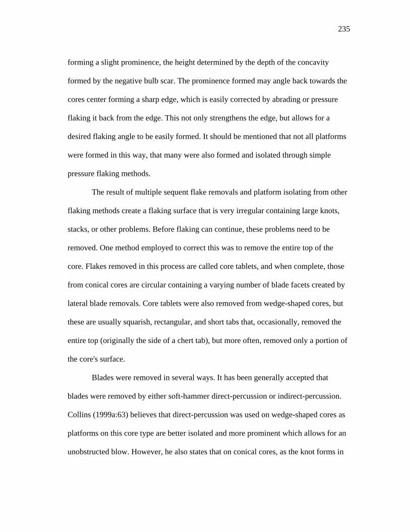
235
forming a slight prominence, the height determined by the depth of the concavity
formed by the negative bulb scar. The prominence formed may angle back towards the
cores center forming a sharp edge, which is easily corrected by abrading or pressure
flaking it back from the edge. This not only strengthens the edge, but allows for a
desired flaking angle to be easily formed. It should be mentioned that not all platforms
were formed in this way, that many were also formed and isolated through simple
pressure flaking methods.
The result of multiple sequent flake removals and platform isolating from other
flaking methods create a flaking surface that is very irregular containing large knots,
stacks, or other problems. Before flaking can continue, these problems need to be
removed. One method employed to correct this was to remove the entire top of the
core. Flakes removed in this process are called core tablets, and when complete, those
from conical cores are circular containing a varying number of blade facets created by
lateral blade removals. Core tablets were also removed from wedge-shaped cores, but
these are usually squarish, rectangular, and short tabs that, occasionally, removed the
entire top (originally the side of a chert tab), but more often, removed only a portion of
the core's surface.
Blades were removed in several ways. It has been generally accepted that
blades were removed by either soft-hammer direct-percussion or indirect-percussion.
Collins (1999a:63) believes that direct-percussion was used on wedge-shaped cores as
platforms on this core type are better isolated and more prominent which allows for an
unobstructed blow. However, he also states that on conical cores, as the knot forms in
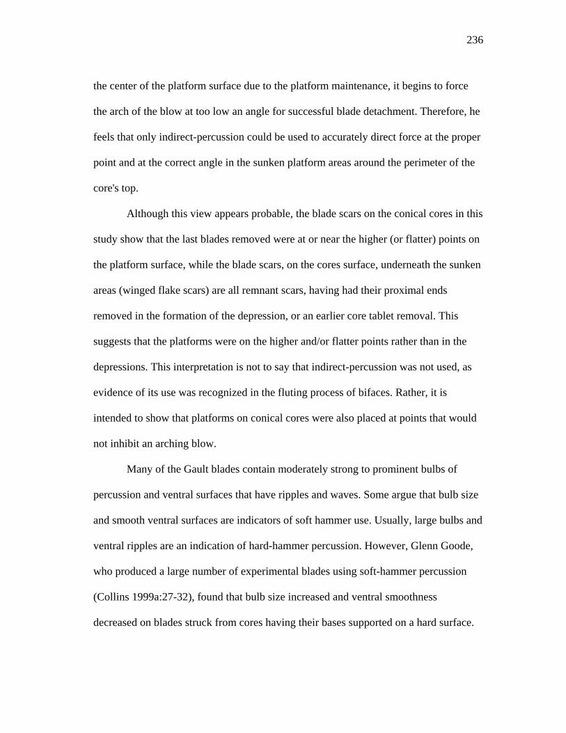
236
the center of the platform surface due to the platform maintenance, it begins to force
the arch of the blow at too low an angle for successful blade detachment. Therefore, he
feels that only indirect-percussion could be used to accurately direct force at the proper
point and at the correct angle in the sunken platform areas around the perimeter of the
core's top.
Although this view appears probable, the blade scars on the conical cores in this
study show that the last blades removed were at or near the higher (or flatter) points on
the platform surface, while the blade scars, on the cores surface, underneath the sunken
areas (winged flake scars) are all remnant scars, having had their proximal ends
removed in the formation of the depression, or an earlier core tablet removal. This
suggests that the platforms were on the higher and/or flatter points rather than in the
depressions. This interpretation is not to say that indirect-percussion was not used, as
evidence of its use was recognized in the fluting process of bifaces. Rather, it is
intended to show that platforms on conical cores were also placed at points that would
not inhibit an arching blow.
Many of the Gault blades contain moderately strong to prominent bulbs of
percussion and ventral surfaces that have ripples and waves. Some argue that bulb size
and smooth ventral surfaces are indicators of soft hammer use. Usually, large bulbs and
ventral ripples are an indication of hard-hammer percussion. However, Glenn Goode,
who produced a large number of experimental blades using soft-hammer percussion
(Collins 1999a:27-32), found that bulb size increased and ventral smoothness
decreased on blades struck from cores having their bases supported on a hard surface.
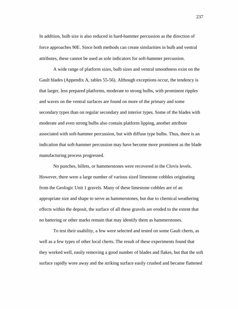
237
In addition, bulb size is also reduced in hard-hammer percussion as the direction of
force approaches 90Ε. Since both methods can create similarities in bulb and ventral
attributes, these cannot be used as sole indicators for soft-hammer percussion.
A wide range of platform sizes, bulb sizes and ventral smoothness exist on the
Gault blades (Appendix A, tables 55-56). Although exceptions occur, the tendency is
that larger, less prepared platforms, moderate to strong bulbs, with prominent ripples
and waves on the ventral surfaces are found on more of the primary and some
secondary types than on regular secondary and interior types. Some of the blades with
moderate and even strong bulbs also contain platform lipping, another attribute
associated with soft-hammer percussion, but with diffuse type bulbs. Thus, there is an
indication that soft-hammer percussion may have become more prominent as the blade
manufacturing process progressed.
No punches, billets, or hammerstones were recovered in the Clovis levels.
However, there were a large number of various sized limestone cobbles originating
from the Geologic Unit 1 gravels. Many of these limestone cobbles are of an
appropriate size and shape to serve as hammerstones, but due to chemical weathering
effects within the deposit, the surface of all these gravels are eroded to the extent that
no battering or other marks remain that may identify them as hammerstones.
To test their usability, a few were selected and tested on some Gault cherts, as
well as a few types of other local cherts. The result of these experiments found that
they worked well, easily removing a good number of blades and flakes, but that the soft
surface rapidly wore away and the striking surface easily crushed and became flattened
238
that required a frequent shifting of the cobble's striking surface. In addition, their
density and weight often made it difficult to remove large or thick flakes from some of
the cherts. Depending the amount of force applied and the striking angle, bulbs on
flakes removed using these limestone hammerstones varied from diffuse to prominent
types with some of the bulbed specimens also having a slight platform lipping. The
combination of these findings and the abundance of these cobbles suggests a probable
chance that they played a part in the Clovis knapping activities at Gault.
In sum, the study of the blade and core attributes (i.e. platform preparation,
platforms, bulbs of percussion, ventral smoothness, indicate that indirect percussion,
hard-hammer direct percussion, and soft-hammer direct percussion) were used to
produce Gault's blades. The fact that some attributes, such as increased bulb size for
example, can be produced either by hard-hammer (or soft-hard hammer) percussion or
by soft-hammer percussion when cores are supported on a hard surface, often makes it
difficult to determine the exact method used. However, it is doubtful that any one
method was used throughout the entire process, whatever the core type, but that the
extent of use, for any one method, was dependant upon individual skill and knapability
of the raw material.
Regardless of the care taken in platform preparation or the method used to
remove blades, not all blade removals were successful. For example, a misdirected
glancing blow may only remove a thin narrow blade with varying termination types, a
blow too far back from the edge may result in a large blade-like flake, split the core, or
cause fracture to plunge and remove the entire distal end of the core. Additional
239
factors, such as insufficient force, improper angle of blow, inclusions, or cracks may
result in short or wide blades and blade-like flakes, irregular or bending blades, and
hinging or step fracture terminations.
Each of the above failures created an individual problem that must be corrected
if flaking was to continue on the core. The primary concern was to maintain prominent
straight ridges and when hinges, stacks, or other problems occur, specific flaking
procedures were employed in order to re-establish the ridge. Many of these problems
were corrected by lateral flaking directed into or under the problem. This procedure can
be noted on blades having radial and or lateral scars on their dorsal surfaces.
Occasionally, flaking from the distal end of the core will restore the core face. Blades
having bi-directional dorsal flaking often reflect this procedure. However, flaking from
both ends may have been performed if a better platform presented itself on the
opposing end, which would also produce a bi-directional dorsal surface. Flakes
removed during these procedures are called trimming flakes (Movius, Jr., David,
Bricker, and Clay 1968:5) or recovery flakes (Collins 1999a:23).
One of the more interesting findings noted during this analysis centers on the
use of the cresting technique. Cresting is usually considered as a technique associated
with initial blade core preparation where either an entire edge or portions of an edge
are straightened and isolated that will serve as a guide for beginning the blade removal
process. However, two blades re-fitted together show that cresting was also used to
straighten ridges throughout the blading process.
240
The two blades were co-joined together with one blade fitting directly over and
angling to the side of the other. Both blades are interior types with the uppermost blade
being a typical blade and the lower blade having a partial cresting, which exemplifies
that cresting was being performed after the blade removal process, had begun. This fact
also explains the relative abundance of crested blades recovered in the assemblage,
especially because the favored raw material forms were square sided tabs, which did
not need cresting. Even most of the cobbles examined were found to contain enough
suitable angles to initiate the blade removal process without the necessity for cresting.
The lithic materials (i.e., blades, cores, core tablets, and associated reduction
debris) were found within two geologic units, the Clovis clay (Geologic Unit 3a) and
the Clovis soil (Geologic Unit 3b). The majority of the lithics were found in the Clovis
clay unit, which accounted for approximately twice the number than was found in the
Clovis soil unit. A study of the technological traits between the two units found no
difference in the manufacturing strategies employed, but did note an increase in blade
production during the occupation of the Clovis soil.
The Gault blades were compared to six other Clovis aged sites having blade
assemblages. These sites are the Adams site in Kentucky, Pavo Real in central Texas,
Green Cache from Blackwater Draw in New Mexico, Gault 1 (1990 UT excavation),
Richey Roberts site in Washington, and the Keven Davis Cache in central Texas.
Where possible, the blades from each of these sites were divided into the major blade
categories (i.e., primary, secondary, and interior) and compared to the appropriate
category established for Gault.
241
The Adams site and Pavo Real are the only sites with data available on primary
blades for comparison to Gault. It was found that the Gault primary blades are slightly
smaller than those from either of the two sites but are almost equal in the dimension
ratios (index of curvature, width-to-length, length, width, and thickness ratios) for Pavo
Real (the only site of the two having computed ratios). This is not surprising as both
Pavo Real and Gault are primary quarry and quarry camps where the entire
manufacturing sequences were performed, therefore, it is more likely that primary
blades would occur in greater numbers on these sites than at non-quarry camps.
Although, the Adams site is also a manufacturing site, there is no natural chert source
at the site, which places it as either a quarry or base camp (Dickens and Dockall
1993:64-65). Platform size and angles for primary blades are available for only Pavo
Real, which are smaller than Gault's, but have almost identical angles.
Five of the sites have data available on secondary blades. From these data, it
was found that the Gault blades are smaller and thinner than those from all sites except
the Adams site whose single specimen is approximately the same size as the average
for the Gault blades. The index of curvature ratios show that the Gault secondary
blades (all types) are significantly flatter than those from all the other sites except for
Pavo Real, which are less, curved than Gault. The width-to-length ratio for Gault are
less than all sites except for Richey Roberts and the Adams site which are
approximately the same. Some slight variances between the length, width, and
thickness ratios occur between most of the different sites, with the largest differences
occurring between the Green and Keven Davis blade caches.
242
The only dimensions provided for platform width and thickness are from the
Keven Davis cache and Pavo Real from which Gault was found to be wider and thicker
than the Keven Davis blades and very close to Pavo Real. However, the platform
angles vary widely between all sites with a range between 42.5° (Green cache) and 78°
(Pavo Real). The Gault platform angles average 74.2°, which are closest to Pavo Real
than any of the others. The variances in platform angle may be attributed to a number
of factors, which include raw material type, method of removal, blade type (i.e., regular
irregular, or corner/side removal, and/or sample size).
All six of the sites have comparable data for interior blades. The Gault interior
blades were found to be shorter than those from the Keven Davis and Green caches but
longer than from the other sites with the widest blades coming from the Adams site,
and the Keven Davis and Green caches. The Gault blades have the lowest index of
curvature closely followed by Pavo Real with the highest curvatures from the Richey
Roberts site and the Keven Davis cache. The dimension ratios are very close between
all the sites except for the Keven Davis and Green caches which have the largest width-
to-length and length ratios and the Adams site and Pavo Real which are the thickest.
The platform dimensions for Gault are wider than the interior blades from the
Keven Davis cache and the Adams site, but are narrower than those from Pavo Real.
The platform angles were found to vary little between all sites with a range of 60°
(Green Cache) and 70° (Keven Davis Cache).
These comparisons show that Gault and Pavo Real blades (all types) share the
closest affinities between each other with minor variances in blade curvature, platform
243
size and thickness. As mentioned previously, this similarity can be attributed to the fact
that both sites are primary quarry or quarry camp sites, while the other sites, some of
which are also manufacturing sites, are not located on or near a raw material source.
This fact indicates that initial testing and reduction were performed at a quarry some
distance from the final manufacturing site, which explains the lack of primary and
other blade debris found. The sites having the biggest differences from Gault are the
blades in the Keven Davis and Green caches. The fact that these blades were found
grouped together suggests that they were regarded with some significance. Aside from
some ceremonial or spiritual context, the answer may be as simple as that they
represent the preferred blade form. That is, these blades were selected out of all those
produced at the quarry or manufacturing site as having the most value. Their size and
shape being the form most favored for transport and use when seasonal movements
took these folks away from any suitable raw material sources. Thus, the blades that
were left at the manufacturing site represent rejects or manufacturing failures and
debris.
This view, however, does not mean that these "rejects" did not have some
value. It is apparent that (although they were not selected for transport) many contain
modifications and obvious use-related wear that indicate their use as tools. This
conclusion may indicate a strategy for a reluctance to utilize the "best" blades at a site
where so many other, less preferred blades (and other flake debris) abound, most of
which, easily serve as efficient tools suitable for whatever tasks are required during the
occupation of the quarry or manufacturing site.

244
In conclusion, this chapter presents a study of the largest assemblage of Clovis
blades, blade cores, and manufacturing debris recovered from a site in North America.
Previously, the largest number of Clovis blades and cores available for study were
found in caches of several dozen (or less) blades and blade fragments or occasional
finds from sites having known Clovis aged contexts. The result of this study has
expanded our current views on the Clovis tool kit and added a number of new insights
into our knowledge of Clovis lithic technology.
245
CHAPTER IV
CONCLUSIONS
This study has been an analysis of 1026 Clovis lithic artifacts recovered during
two field schools conducted by TAMU during 2000 and 2001 at the Gault site
(41BL323), a multi-component site located in Bell County, Texas. The site is located in a
small valley adjacent to Buttermilk Creek whose headwaters originate near the upper
portion of the valley. The Clovis artifacts were found in two geologic units (3a and 3b).
Geologic Unit 3a is a clay that formed in a small pond behind a gravel bar at the edge of
an ancestral Buttermilk Creek. Geologic Unit 3b is clay that comprised the floodplain of
an ancestral Buttermilk Creek. This unit has undergone slight pedogensis. Both of these
units were capped over by younger deposits.
The analyzed artifacts include 4 projectile points, 55 bifaces, 1 hammerstone, 464
blades, 3 blade refits, 50 blade cores, 36 core tablets, 185 overshot flakes, 114 large
flakes, 63 sequent flakes, and 51 problem removal flakes. All but three of these artifacts
were made from local chert. The three exceptions include a blade fragment and a
hammerstone made of quartzite and the proximal half of a projectile point made of a
yellow jasper. Although quartzite often occurs within some of the regional gravel
deposits, it has not been noted locally. However, the single hammerstone made from a
quartzite cobble does indicate a probable occurrence in the near vicinity. No jasper occurs
within the region. Some forms of red and yellow jaspers do occur within and east of the
Brazos River as well as in south Texas. It is rare or absent within the central Texas region.
246
The remaining lithic artifacts were all made of local chert. The immediate region
surrounding the Gault site contains a number of excellent varieties of chert. Several
varieties of chert, including one excellent type, occur on the valley slopes adjacent to
Gault. This type is a fine-grained opaque gray chert that was abundant and much favored,
not only by the Clovis knappers but also by later peoples as well. This is evident in the
upper cultural layers where tremendous numbers of large flakes and chunks can still be
found.
Unfortunately, very little of this chert remains in its tabular or nodular form. Over
the last 20 years or so, modern flintknappers exploited the site by on site spalling and
removing nodules. Currently, numerous flake debris from these activities litters the site
and has been mixed with much of the prehistoric surface debris. Chert, however, is still
abundant in the area, but most is a coarse grained lighter colored type that is of an inferior
flaking quality.
Interestingly, the chert materials recovered in the Clovis levels have a chemical
staining that has colored the surface of this material a yellow-brown or green. Since the
Clovis materials were excavated from a creek bank deposit, this staining obviously
occurred as a result of chemicals within the waters within Buttermilk Creek that
commonly covered the site. This is substantiated by the fact that those types of chert
found above the creek banks are not colored. Instead, they remain in their original gray
color or, occasionally, have patinated a gray-white. Although, at first it was thought this
staining appeared to be a signature of Clovis materials from Gault, it has now been
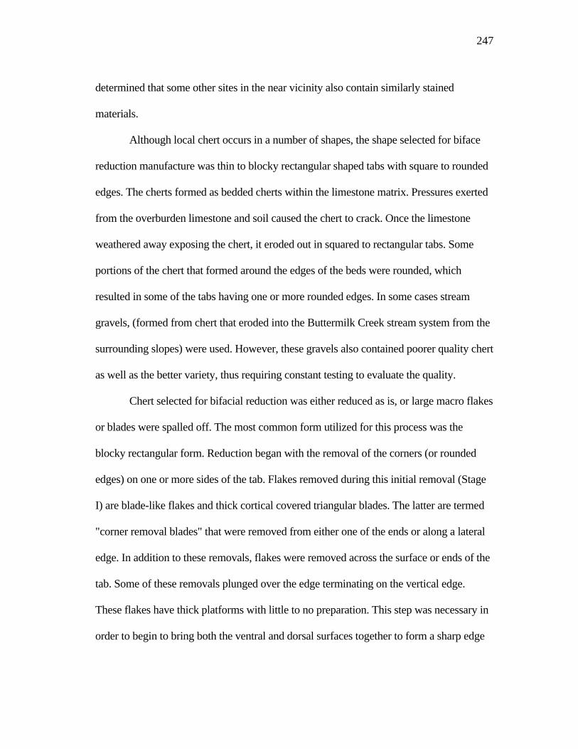
247
determined that some other sites in the near vicinity also contain similarly stained
materials.
Although local chert occurs in a number of shapes, the shape selected for biface
reduction manufacture was thin to blocky rectangular shaped tabs with square to rounded
edges. The cherts formed as bedded cherts within the limestone matrix. Pressures exerted
from the overburden limestone and soil caused the chert to crack. Once the limestone
weathered away exposing the chert, it eroded out in squared to rectangular tabs. Some
portions of the chert that formed around the edges of the beds were rounded, which
resulted in some of the tabs having one or more rounded edges. In some cases stream
gravels, (formed from chert that eroded into the Buttermilk Creek stream system from the
surrounding slopes) were used. However, these gravels also contained poorer quality chert
as well as the better variety, thus requiring constant testing to evaluate the quality.
Chert selected for bifacial reduction was either reduced as is, or large macro flakes
or blades were spalled off. The most common form utilized for this process was the
blocky rectangular form. Reduction began with the removal of the corners (or rounded
edges) on one or more sides of the tab. Flakes removed during this initial removal (Stage
I) are blade-like flakes and thick cortical covered triangular blades. The latter are termed
"corner removal blades" that were removed from either one of the ends or along a lateral
edge. In addition to these removals, flakes were removed across the surface or ends of the
tab. Some of these removals plunged over the edge terminating on the vertical edge.
These flakes have thick platforms with little to no preparation. This step was necessary in
order to begin to bring both the ventral and dorsal surfaces together to form a sharp edge
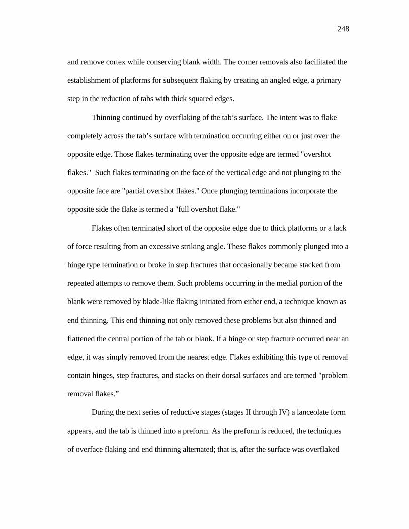
248
and remove cortex while conserving blank width. The corner removals also facilitated the
establishment of platforms for subsequent flaking by creating an angled edge, a primary
step in the reduction of tabs with thick squared edges.
Thinning continued by overflaking of the tab’s surface. The intent was to flake
completely across the tab’s surface with termination occurring either on or just over the
opposite edge. Those flakes terminating over the opposite edge are termed "overshot
flakes." Such flakes terminating on the face of the vertical edge and not plunging to the
opposite face are "partial overshot flakes." Once plunging terminations incorporate the
opposite side the flake is termed a "full overshot flake."
Flakes often terminated short of the opposite edge due to thick platforms or a lack
of force resulting from an excessive striking angle. These flakes commonly plunged into a
hinge type termination or broke in step fractures that occasionally became stacked from
repeated attempts to remove them. Such problems occurring in the medial portion of the
blank were removed by blade-like flaking initiated from either end, a technique known as
end thinning. This end thinning not only removed these problems but also thinned and
flattened the central portion of the tab or blank. If a hinge or step fracture occurred near an
edge, it was simply removed from the nearest edge. Flakes exhibiting this type of removal
contain hinges, step fractures, and stacks on their dorsal surfaces and are termed "problem
removal flakes.”
During the next series of reductive stages (stages II through IV) a lanceolate form
appears, and the tab is thinned into a preform. As the preform is reduced, the techniques
of overface flaking and end thinning alternated; that is, after the surface was overflaked
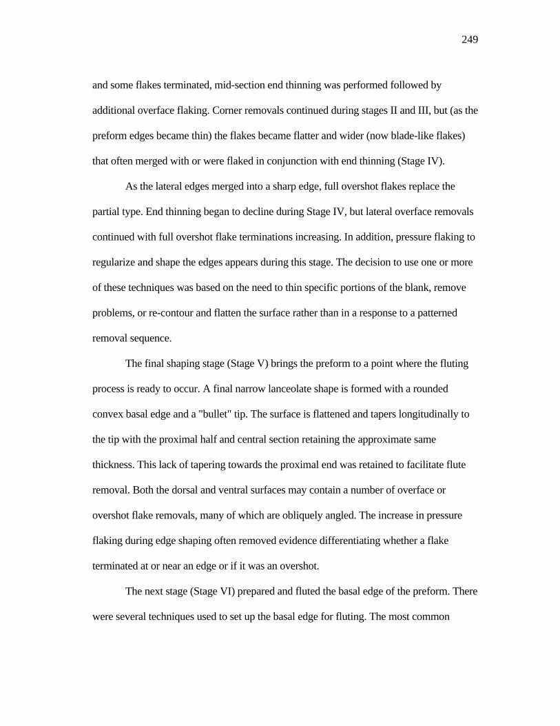
249
and some flakes terminated, mid-section end thinning was performed followed by
additional overface flaking. Corner removals continued during stages II and III, but (as the
preform edges became thin) the flakes became flatter and wider (now blade-like flakes)
that often merged with or were flaked in conjunction with end thinning (Stage IV).
As the lateral edges merged into a sharp edge, full overshot flakes replace the
partial type. End thinning began to decline during Stage IV, but lateral overface removals
continued with full overshot flake terminations increasing. In addition, pressure flaking to
regularize and shape the edges appears during this stage. The decision to use one or more
of these techniques was based on the need to thin specific portions of the blank, remove
problems, or re-contour and flatten the surface rather than in a response to a patterned
removal sequence.
The final shaping stage (Stage V) brings the preform to a point where the fluting
process is ready to occur. A final narrow lanceolate shape is formed with a rounded
convex basal edge and a "bullet" tip. The surface is flattened and tapers longitudinally to
the tip with the proximal half and central section retaining the approximate same
thickness. This lack of tapering towards the proximal end was retained to facilitate flute
removal. Both the dorsal and ventral surfaces may contain a number of overface or
overshot flake removals, many of which are obliquely angled. The increase in pressure
flaking during edge shaping often removed evidence differentiating whether a flake
terminated at or near an edge or if it was an overshot.
The next stage (Stage VI) prepared and fluted the basal edge of the preform. There
were several techniques used to set up the basal edge for fluting. The most common
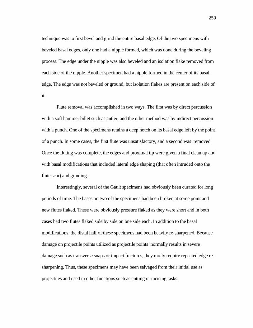
250
technique was to first bevel and grind the entire basal edge. Of the two specimens with
beveled basal edges, only one had a nipple formed, which was done during the beveling
process. The edge under the nipple was also beveled and an isolation flake removed from
each side of the nipple. Another specimen had a nipple formed in the center of its basal
edge. The edge was not beveled or ground, but isolation flakes are present on each side of
it.
Flute removal was accomplished in two ways. The first was by direct percussion
with a soft hammer billet such as antler, and the other method was by indirect percussion
with a punch. One of the specimens retains a deep notch on its basal edge left by the point
of a punch. In some cases, the first flute was unsatisfactory, and a second was removed.
Once the fluting was complete, the edges and proximal tip were given a final clean up and
with basal modifications that included lateral edge shaping (that often intruded onto the
flute scar) and grinding.
Interestingly, several of the Gault specimens had obviously been curated for long
periods of time. The bases on two of the specimens had been broken at some point and
new flutes flaked. These were obviously pressure flaked as they were short and in both
cases had two flutes flaked side by side on one side each. In addition to the basal
modifications, the distal half of these specimens had been heavily re-sharpened. Because
damage on projectile points utilized as projectile points normally results in severe
damage such as transverse snaps or impact fractures, they rarely require repeated edge re-
sharpening. Thus, these specimens may have been salvaged from their initial use as
projectiles and used in other functions such as cutting or incising tasks.
251
The reductive techniques discussed above are generally recognized as part of the
known Clovis technology. However, some of the techniques observed at Gault were either
not previously recognized or looked at in a different perspective. Not unlike other Clovis
sites, the material form used at Gault included thin to blocky chert and large spalls, blades,
and flakes. Whereas, all these blank forms were used at Gault, the most common form
used at Gault was the thin to blocky tabs.
The reduction of large macro-flakes (whether flakes or blades) are relatively thin
with most of their edges sharp. Because these edges are already sharp, they require little
manipulation to begin platforming for the overface flaking and shaping process. In
addition, the flatter and thin nature of these blanks also enable the knapper to skip some of
the reduction " stages" usually identified by analysts. However, the blocky tabs require a
different approach to begin the thinning process, due to having steep vertical edges.
As mentioned above, the initial step in this process was to strike off long blades
from the corners along the longitudinal edges or ends of the tab. This technique has
previously only been associated with blade core preparation. However, adapting blade
techniques in other applications is not surprising as blading is a common strategy within
Clovis technology (Collins 1999a:19-26). The fluting process, for example, is also a
specialized form of blading; therefore, applying a blading technique in the manipulation
of blocky tab reduction should not be unexpected. Evidence for this flaking technique was
observed, not only on the edges of some of the bifaces but also on the distal edges of
some overshot flakes.
252
The end thinning technique is a flaking trait that has been only occasionally
identified within the Clovis manufacturing process (Callahan 1979; Fogelman 1986;
Sanders 1983, 1990). It was first described by Callahan (1979) in his replication studies
on fluted point manufacturing and later observed within the reductive process at the
Adams site (Sanders 1983, 1990). One of the reasons for not recognizing it may be its
resemblance to fluting, causing researchers to interpret end thinning as "early" fluting
(Howard 1990:257-258) and not as a repeated reduction technique. However, the use of
the end thinning technique was observed at both the Adams and Gault sites throughout,
not only in the primary reductive stages, but continuing until the final shaping process
prior to fluting.
Another trait gaining significant recognition with Clovis technology is the use of
overshot flaking. Some feel this technique is an intentional flaking strategy (Bradley
1982, 1991, 1993; Morrow 1986; Collins 1999a, 1999b; Johnson 1993), while others feel
it to be the result of knapping errors (Callahan 1979; Verrey 1986; Patten 1999; Sanders
1983, 1990). The results of the study of the Gault overshots suggest that, in part, overshot
flaking probably was an intentional strategy.
Two types of overshot flakes were identified from the Gault assemblage. These
are partial overshots which were removed from the squared edges of the blocky tabs and
terminated only partway on the tab's vertical edge, and full overshots which were
removed from thinner preforms and whose terminations plunged completely through the
preform removing portions of both the dorsal and ventral surfaces. Partial overshots were
obviously intentional removals. These were removed beginning with initial cortex
253
removal and continued until both the dorsal and ventral surfaces came together into a
sharp edge. Not only did these removals begin to bring the edges of the two faces
together, but the plunging nature of the termination also aided in guiding additional flake
fracture and subsequent platform formation.
Full overshot removals, however, contain a different set of problems. One of the
primary factors surrounding full overshot flaking is the unpredictable nature of its
termination. As any modern flint knapper can readily testify, it is difficult to control
exactly where a plunging fracture will occur or how much of the edge will be removed.
Through a comparison of the width of the different biface stages and the data derived
from the full overshot flakes, it was concluded that a 10% to 15% edge loss per flake
removal did not inhibit continued reduction. However, it was found that only slightly over
50% of the full overshots fell with this category and that the average of edge loss was
27%, reinforcing its unpredictability. Thus, an accepted full overshot flake removal, even
if all the criteria (i.e., proper platform, support, applied force and striking angles) were
met, was 50/50 at best. This conclusion is further compounded when considering that
multiple removals were performed on each biface.
Keeping these issues in mind, why was full overshot flaking intentionally
performed? In retrospect, full overshot terminations were probably not the intended
result. Rather, they were probably the result of overface flaking where the intention was to
remove flakes completely across the face of the preform with the idea that termination
would occur at or near the opposite edge. Some edge removal was considered acceptable,
but (because it is difficult to consistently control all factors and criteria for such removals)

254
terminations often plunged near the edge removing more of the edge than was intended.
Where flakes terminated near the edge, as well as some that overshot, the edge was often
flaked back from the opposite edge to flatten or smooth the termination point and/or
realign the edge. This often makes it difficult to distinguish flakes that terminated near the
edge from those that plunged over.
The second part of this study centered on blade manufacture. It was immediately
apparent that the blade assemblage was comprised of a number of different blade types.
Initial divisions began with both regular and irregular forms separated into primary,
secondary, and interior types and a specialized form known as crested blades. As analysis
proceeded, the primary and secondary blades were further divided into another specialized
form termed corner removal blades.
Not surprisingly, this variation in blade types also varies in their descriptions.
These variations include blades as having cross-sections that vary from almost flat, to
prominently triangular, with edge angles that range from acute to abrupt, have single or
multiple longitudinal, or occasionally, lateral flake scar ridges, and longitudinal sections
that range from strongly curved to flat. Blade lengths (for all types) average between 63
mm and 96 mm in length, have platforms averaging 4.1 mm wide and 10.2 mm thick,
with an average platform angle of 72.7°, and platform preparations that may be
unprepared or heavily modified by isolation, grinding, and faceting. The bulbs of
percussion are often flat or diffuse. They may also contain moderate to strongly prominent
bulbs with ventral surfaces that may be smooth or have varying amounts of ripples and
waves.
255
These findings differ from the previously accepted Clovis blade definition which
describes Clovis blades as having small platforms that may be wide but not deep, flat
bulbs of percussion, minimal amounts of ripple marks on the ventral surface giving a
smooth appearance, are generally long and curved in longitudinal cross-section (Collins
1999a:63,178). However, the presence of so many blade variations should not be
surprising as the Gault site is a quarry workshop and camp where a variety of lithic tools
were manufactured. During the blade manufacturing process, blade types and methods of
removal changed as the process continued. This resulted in the accumulation of varying
amounts of blade core preparation debris, blades that failed or were rejected, and
additional amounts of waste debitage, from core and biface reduction.
On the other hand, successful blades, or those that met the criteria for the intended
product, would have been removed for utilization elsewhere. It is these blades, often
found in individual caches (Green 1963:145-163; Collins 1999a:75-143) that formed the
initial Clovis blade descriptions. Therefore, one could reasonably argue that such blades
represent the true blade form and that all the others are merely marginal or unsuitable and
rejected forms. Undoubtedly, this supposition is true; however, even though many of the
blades left at the quarry site do not fit into the classic definition, many were utilized as
tools (Lohse et. al. 2002). Therefore, it is apparent that the Clovis folks utilized a wide
range of blade forms, at least in the proximity of lithic sources, if not elsewhere.
Blade manufacture began with the selection of the raw material. With the single
exception of a quartzite blade fragment, all the blades were made of local chert. Both
creek gravels and the blocky tabs from the surrounding slopes were utilized. Cobble use
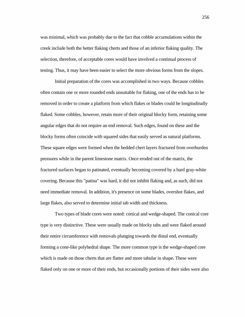
256
was minimal, which was probably due to the fact that cobble accumulations within the
creek include both the better flaking cherts and those of an inferior flaking quality. The
selection, therefore, of acceptable cores would have involved a continual process of
testing. Thus, it may have been easier to select the more obvious forms from the slopes.
Initial preparation of the cores was accomplished in two ways. Because cobbles
often contain one or more rounded ends unsuitable for flaking, one of the ends has to be
removed in order to create a platform from which flakes or blades could be longitudinally
flaked. Some cobbles, however, retain more of their original blocky form, retaining some
angular edges that do not require an end removal. Such edges, found on these and the
blocky forms often coincide with squared sides that easily served as natural platforms.
These square edges were formed when the bedded chert layers fractured from overburden
pressures while in the parent limestone matrix. Once eroded out of the matrix, the
fractured surfaces began to patinated, eventually becoming covered by a hard gray-white
covering. Because this "patina" was hard, it did not inhibit flaking and, as such, did not
need immediate removal. In addition, it's presence on some blades, overshot flakes, and
large flakes, also served to determine initial tab width and thickness.
Two types of blade cores were noted: conical and wedge-shaped. The conical core
type is very distinctive. These were usually made on blocky tabs and were flaked around
their entire circumference with removals plunging towards the distal end, eventually
forming a cone-like polyhedral shape. The more common type is the wedge-shaped core
which is made on those cherts that are flatter and more tabular in shape. These were
flaked only on one or more of their ends, but occasionally portions of their sides were also
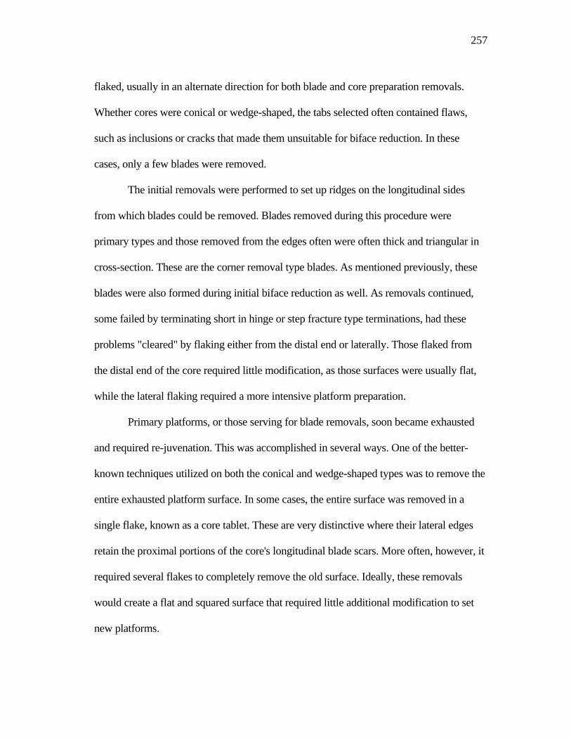
257
flaked, usually in an alternate direction for both blade and core preparation removals.
Whether cores were conical or wedge-shaped, the tabs selected often contained flaws,
such as inclusions or cracks that made them unsuitable for biface reduction. In these
cases, only a few blades were removed.
The initial removals were performed to set up ridges on the longitudinal sides
from which blades could be removed. Blades removed during this procedure were
primary types and those removed from the edges often were often thick and triangular in
cross-section. These are the corner removal type blades. As mentioned previously, these
blades were also formed during initial biface reduction as well. As removals continued,
some failed by terminating short in hinge or step fracture type terminations, had these
problems "cleared" by flaking either from the distal end or laterally. Those flaked from
the distal end of the core required little modification, as those surfaces were usually flat,
while the lateral flaking required a more intensive platform preparation.
Primary platforms, or those serving for blade removals, soon became exhausted
and required re-juvenation. This was accomplished in several ways. One of the better-
known techniques utilized on both the conical and wedge-shaped types was to remove the
entire exhausted platform surface. In some cases, the entire surface was removed in a
single flake, known as a core tablet. These are very distinctive where their lateral edges
retain the proximal portions of the core's longitudinal blade scars. More often, however, it
required several flakes to completely remove the old surface. Ideally, these removals
would create a flat and squared surface that required little additional modification to set
new platforms.
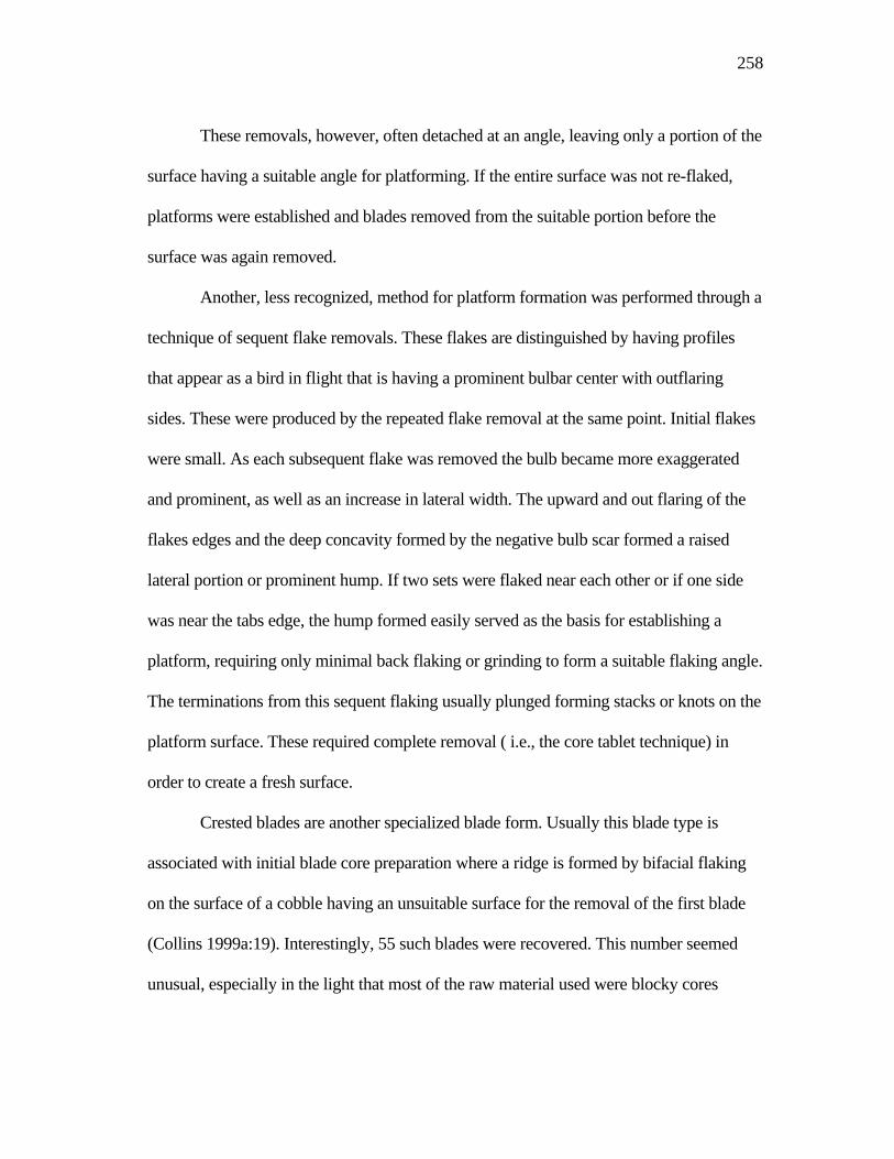
258
These removals, however, often detached at an angle, leaving only a portion of the
surface having a suitable angle for platforming. If the entire surface was not re-flaked,
platforms were established and blades removed from the suitable portion before the
surface was again removed.
Another, less recognized, method for platform formation was performed through a
technique of sequent flake removals. These flakes are distinguished by having profiles
that appear as a bird in flight that is having a prominent bulbar center with outflaring
sides. These were produced by the repeated flake removal at the same point. Initial flakes
were small. As each subsequent flake was removed the bulb became more exaggerated
and prominent, as well as an increase in lateral width. The upward and out flaring of the
flakes edges and the deep concavity formed by the negative bulb scar formed a raised
lateral portion or prominent hump. If two sets were flaked near each other or if one side
was near the tabs edge, the hump formed easily served as the basis for establishing a
platform, requiring only minimal back flaking or grinding to form a suitable flaking angle.
The terminations from this sequent flaking usually plunged forming stacks or knots on the
platform surface. These required complete removal ( i.e., the core tablet technique) in
order to create a fresh surface.
Crested blades are another specialized blade form. Usually this blade type is
associated with initial blade core preparation where a ridge is formed by bifacial flaking
on the surface of a cobble having an unsuitable surface for the removal of the first blade
(Collins 1999a:19). Interestingly, 55 such blades were recovered. This number seemed
unusual, especially in the light that most of the raw material used were blocky cores
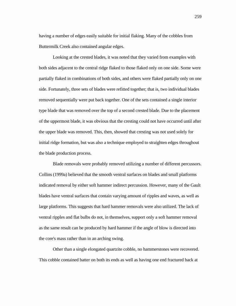
259
having a number of edges easily suitable for initial flaking. Many of the cobbles from
Buttermilk Creek also contained angular edges.
Looking at the crested blades, it was noted that they varied from examples with
both sides adjacent to the central ridge flaked to those flaked only on one side. Some were
partially flaked in combinations of both sides, and others were flaked partially only on one
side. Fortunately, three sets of blades were refitted together; that is, two individual blades
removed sequentially were put back together. One of the sets contained a single interior
type blade that was removed over the top of a second crested blade. Due to the placement
of the uppermost blade, it was obvious that the cresting could not have occurred until after
the upper blade was removed. This, then, showed that cresting was not used solely for
initial ridge formation, but was also a technique employed to straighten edges throughout
the blade production process.
Blade removals were probably removed utilizing a number of different percussors.
Collins (1999a) believed that the smooth ventral surfaces on blades and small platforms
indicated removal by either soft hammer indirect percussion. However, many of the Gault
blades have ventral surfaces that contain varying amount of ripples and waves, as well as
large platforms. This suggests that hard hammer removals were also utilized. The lack of
ventral ripples and flat bulbs do not, in themselves, support only a soft hammer removal
as the same result can be produced by hard hammer if the angle of blow is directed into
the core's mass rather than in an arching swing.
Other than a single elongated quartzite cobble, no hammerstones were recovered.
This cobble contained batter on both its ends as well as having one end fractured back at
260
an angle reminiscent of a gouge. Prominent within the creek gravels, were limestone
nodules of varying sizes and shapes. Many of these seemed suitable for use as a
hammerstone. Subsequent flaking experiments showed that these nodules could have
been used as hammerstones, but that their surfaces rapidly crushed and became
inefficient. No direct evidence for indirect percussion was noted, but the fact that several
of the projectile points appeared to have been fluted by this means, one cannot entirely
rule out its use. The majority of both the bifaces and blades were more prevalent in the
Clovis clay (Geologic Unit 3a) geologic unit than the Clovis soil (Geologic Unit 3b). The
presence of late stage bifaces (i.e., stages V, VI, and VII) were much reduced or totally
lacking in Geologic Unit 3b. A single exception, was a finished point found in Geologic
Unit 3b. However, there were more secondary full overshot flakes and approximately
one-half the number of interior full overshot flakes in Geologic Unit 3b than Geologic
Unit 3a. This suggests that middle stage reduction occurred consistently within both units.
Since evidence indicates that interior full overshot flaking continued until the final
preform stage prior to fluting, it can be inferred from their presence that late stage
reduction also occurred in Geologic Unit 3b. Because the Gault Site covers a large area,
the lack of late stage bifaces from Geologic Unit 3b can be attributed to sample size bias.
A study of the manufacturing debris for blades (i.e., blades blade cores, core
tablets, and associated debris) found that( like the bifaces) most were found in the Clovis
clay (Geologic Unit 3a). This accounted for approximately twice the amount than was in
the Clovis soil (Geologic Unit 3b). In addition, there was no indication that the blade
manufacturing technologies employed changed between the occupations of the two units.
261
There were, however, a higher number of crested blades recovered from Geologic Unit 3b
(almost equaling those from Geologic Unit 3a), but because this is a technique used to re-
align flaking ridges, it does not indicate a technological change.
The technological traits from the Gault assemblage were compared to seven other
Clovis sites. These sites include the Adams site in western Kentucky, Aubrey site in
north-central Texas, the Pavo Real site in south-central Texas, the Green Cache from
Blackwater Draw in New Mexico, Gault 1 (1990 UT excavation), Richey Roberts site in
Washington, and the Keven Davis Cache in central Texas. Two of these sites are blade
caches with no bifaces present, and the Aubrey site contained only a fragment of a Clovis
point.
One of the most abundant attributes for Clovis technology is the overshot flaking
technique. Evidence for this type flaking has been noted at a number of Clovis sites as
well as remnant scars noted on many finished points found in both isolated and site
contexts. It should be stressed that overface flaking noted on the Gault bifaces resembles
overshots but terminates near the opposite edge without plunging over it. Any subsequent
flaking back of that edge may obscure whether that flake terminated near the edge or
actually plunged over it. Of the sites investigated for this study, the use of overshot
flaking was identified at the Adams site Sanders (1990), Pavo Real (Collins et al. 2003),
the Richey Roberts site (Gramley 1993), and the Aubrey site (Ferring 1990:11) where a
possible overshot flake was recovered.
One attribute rarely discussed with Clovis reduction is the end thinning technique.
Such a strategy was noted at the Adams site where it was identified during the reduction
262
stages II through IV (Sanders 1990:32-42) and on a single early stage bifacial fragment
from Pavo Real (Collins et al. 2003:100). Although not specifically assigned to any
particular reductive stage, end thinning was observed on some illustrations of the bifaces
and "knives" from the Richey Roberts site (Gramley 1993:37,41-42).
The Gault blades were also compared to six sites having blade assemblages. These
sites include the Adams site, Pavo Real, the Green Cache, Gault 1, Richey Roberts, and
the Keven Davis Cache. Although a few blade fragments and a core tablet were recovered
from the Aubrey site (Ferring 1990:11), no descriptions are available. In order to properly
evaluate blades from each site with the Gault analysis, the blades from each site were
divided into primary, secondary, interior, or specialized (crested) categories.
The only site, other than Gault, with primary blades is the Adams site, and the
dimensions for both sites (index of curvature, width-to-length, width, and thickness ratios)
are almost equal. The comparison of secondary blades with five sites ( i.e. Adams, Green
and Keven Davis caches, Pavo Real, and Richey Roberts) having secondary blade types
found that the Gault blades were smaller and thinner from all sites except the Adams site.
The index of curvature calculations, however, show the Gault blades to be flatter than all
sites except for Pavo Real and the width-to length ratios are less for all sites except for
Richey Roberts and Adams which are approximately the same. The interior blades from
all sites are very similar with the Gault blades being slightly shorter than those from both
the Green and Keven Davis caches but longer than those from the other sites. In addition
the Gault blades have the lowest index of curvature, closely followed by Pavo Real.
263
The only sites with available platform widths and thicknesses are Pavo Real and
the Keven Davis Cache in which Gault was found to be wider and thicker from Keven
Davis and very close to Pavo Real. The platform angles between Pavo Real and Gault
were also very similar and steeper than those from the Keven Davis Cache.
These findings show that blades from the Adams and Pavo Real sites are more
similar to Gault than from the other sites. This, however, is not surprising when one
considers that Gault, Pavo Real, and Adams are lithic manufacturing sites containing large
numbers of rejected and failed blades along with intended forms, while the Green and
Keven Davis caches and, to some degree, Richey Roberts are isolated concentrations
composed solely of intended blades. This conclusion, however, does not mean that the
failed and/or rejected blades left at the manufacturing sites were not valued as tools. In
fact, it was noted that many of these blades at Gault contain wear patterns supporting
evidence of use. Rather, it appears that those chosen for transport contain certain specific
preferred characteristics not present on those left behind.
In conclusion, this analysis has found that a number of different reduction
strategies were employed at the Gault site. Although several strategies (i.e., overface
flaking on bifaces, core tablet and sequent flake removals for platform rejuvenation and
formation on blade cores) were consistently used, there was no specific sequence
followed for the occurrence of their use other than as a result of variances in raw material
forms and as flaking problems developed. In addition, some techniques (such as blading)
were modified and incorporated into the reduction of both biface and blade manufacture.

264
Thus, this study has expanded our current views and added a number of new insights into
our current knowledge of Clovis lithic technology.
265
REFERENCES
Adovasio, J. M. (with Jake Page) 2002 The First Americans. Random House, Inc., New York.
Andrefsky, William Jr. 1998 Lithics Macroscopic Approaches to Analysis. Cambridge Manuals in Archaeology. Cambridge University Press, United Kingdom.
Banks, Larry D. 1990 From Mountain Peaks to Alligator Stomachs: A Review of Lithic Sources in the Trans-Mississippi South, the Southern Plains, and Adjacent Southwest. Oklahoma Anthropological Society Memoir #4. Norman, Oklahoma.
Bar-Josef, Ofer 1987 Pleistocene Connections Between Africa and Southwest Asia: An Archaeological Perspective. The African Archaeological Review, 5:29-38.
Birmingham, William W., and James E. Bluhm 2003 A Clovis Polyhedral Blade Core from Northwest Victoria County, Texas. La Tierra 30(3&4):55-58.
Bonnichsen, Robson 1977 Models for Deriving Cultural Information from Stone Tools. National
Museums of Canada, Ottawa.
Bordes, Francois 1961 Typologie du Paleolithique ancient et moyen. Delmas, Bordeaux.
Bordes, Francois and Don Crabtree 1969 The Corbolic Blade Technique and other Experiments. Tebiwa 12(2):1-21.
Bouldurian, Anthony T. 1985 Variability in Flintworking Technology at the Krajacic Site: Possible Relationships to the Pre-Clovis Paleoindian Occupation of the Cross Creek Drainage in Southwestern Pennsylvania. Unpublished Ph.D dissertation, University of Pittsburgh.
1991 Folsom Mobility and Organization of Lithic Technology: A View from Blackwater Draw, New Mexico. Plains Anthropologist 36-137: 281-296.
266
Bouldurian, Anthony T., and John L. Cotter 1999 Clovis Revisited: New Perspectives on Paleoindian Adaptations from Blackwater Draw, New Mexico. The University Museum, University of Pennsylvania, Philadelphia.
Bradley, Bruce A. 1982 Flaked Stone Technology and Typology. In The Agate Basin Site: A Record of the Paleoindian Occupation of the Northwestern High Plains, edited by George C. Frison and Dennis Stanford, pp. 181-208.Academic Press, New York.
1991 Flaked Stone Technology in the Northern High Plains. In Prehistoric Hunters of the High Plains Second Edition, pp.369-395, edited by George C. Frison. Academic Press, San Diego, California.
1993 Paleo-Indian Flaked Stone Technology in the North American High Plains. In From Kostenki to Clovis, edited by Olga Soffer and N.D. Praslov, pp. 251-262. Plenum Press, New York.
Bryan, W.A., and Michael B. Collins 1988 Inventory and Assessment of Cultural Resources Above the 1551.5 Foot Contour Line, Stacy Reservoir Recreation Areas, Concho, Coleman and Runnels Counties, Texas. Prewitt and Associates, Inc. Reports of Investigations 57, Austin, Texas.
Butler, B.R. 1963 An Early Man Site at Big Camas Prairie, South Central Idaho. Tebiwa 6(1):22-23.
Callahan, Errett 1979 The Basics of Biface Knapping in the Eastern Fluted Point Tradition: A Manual for Flintknappers and Lithic Analysts. Archaeology of Eastern North America, 7(1):1-179.
Clark, John E. 1987 Politics, Prismatic Blades, and Mesoamerican Civilization. In The Organization of Core Technology, edited by Jay K. Johnson and Carol A. Morrow, pp. 259-284.Westview Press, Boulder.
Collins, Michael A., and P. Headrick 1992 Comments on Kelly's Interpretations of the "Van Autry" Cores. La Tierra 19(4):26-39.
267
Collins, Michael B. 1975 Lithic Technology as a Means of Processual Inference. In Lithic Technology: Making and Using Stone Tools, edited by E. Swanson, pp. 15-34. Mouton: The Hague.
1998 Early Paleoindian Components. In Wilson-Leonard: An 11,000-year Archaeological Record of Hunter-Gatherers in Central Texas, Vol. I: Introduction, Background, and Syntheses, edited by Michael Collins, pp.123-159. Studies in Archaeology 31 Texas Archeological Research Laboratory, The University of Texas at Austin.
1999a Clovis Blade Technology. Texas Archaeology and Ethnohistory Series. The University of Texas Press, Austin.
1999b Clovis and Folsom Lithic Technology on and near the Southern Plains. In Folsom Lithic Technology Explorations in Structure and Variation, edited by Daniel S. Amick, pp. 12-38.International Monographs in Prehistory, Ann Arbor, Michigan.
Collins, Michael B., Dale B. Hudler, and Stephen L. Black 2003 Pavo Real (41BX52): A Paleoindian and Archaic Camp and Workshop on the Balcones Escarpment, South-Central Texas. Studies in Archeology 41, Texas Archeological Research Laboratory, The University of Texas at Austin and Archeological Studies Program Report 50, Environmental Affairs Division, Texas Department of Transportation.
Copeland, Lorrain 2000 Yabrudian and Related Industries: The State of Research in1996. Toward Modern Humans The Yabrudian and Micoquian 400-50 K-years ago, Proceedings of a Congress held at the University of Haifa November 3-9, 1996, edited by Avraham Ronen and Mina Weinstein-Evron, pp. 97-118. BAR International Series 850, Oxford, England.
Cotterell, Brian, and Johan Kamminga 1979 The Mechanics of Flaking. In Lithic Use-Wear Analysis edited by Bryan Hayden, pp. 97-112. Academic Press, New York.
Cox, S.L. 1986 A Re-Analysis of the Shoop Site. Archaeology of Eastern North America 14:101-170
Crabtree, Don E. 1966 A Stoneworker's Approach to Analyzing and Replicating the Lindenmeier Folsom. Tebiwa 9(1):3-39.
268
1968 Mesoamerican Polyhedral Cores and Prismatic Blades. American Antiquity 33:446-478.
1972 An Introduction to Flintknapping. Occasional Papers of the Idaho State University Museum, Number 28, Pocatello, Idaho.
Deller, D. Brian, and Christopher Ellis
1992 Thedford II A Paleo-Indian Site in the Ausable River Watershed of Southwestern Ontario. Memoirs Museum of Anthropology University of Michigan No. 24. Ann Arbor, Michigan.
Dibble, Harold L., and John C. Whittaker 1981 New Experimental Evidence on the Relation Between Percussion Flaking and Flake Variation. Journal of Archaeological Science 8:283-298
Dickens, William A.
1995 Lithic Artifacts from Washington. In The Anson Jones Plantation: Archaeological and Historical Investigations at 41WT5 and 41WT6, Washington County, Texas, edited by Shawn Bonath Carlson, pp.179-206.Reports of Investigations No. 2, Center for Environmental Archaeology, Texas A&M University, College Station.
Dickens, William A., and John E. Dockall 1993 Lithic Analysis. In Archaeological Site Testing and Evaluation on the Henson Mountain Helicopter Range Awss Project Area, Fort Hood, Texas, edited by David L.Carlson, pp.61-82. United States Army Fort Hood Archaeological Resource Management Series, Research Report No. 26.
Dragoo, D.W. 1973 Wells Creek: An Early Man Site in Stewart County, Tennessee. Archaeology of Eastern North America 1:1-56.
Ellis, Christopher, and D. Brian Deller 2000 An Early Paleo-Indian Site Near Parkhill, Ontario. Mercury Series Archaeological Survey of Canada Paper 159. Canadian Museum of Civilization, Hull, Quebec.
Ferring, C. Reid 2001 The Archaeology and Paleoecology of the Aubrey Clovis Site (41DN479) Denton County, Texas. Center for Environmental Archaeology, Department of Geography, University of North Texas, Denton.
269
Flenniken, J. Jeffrey 1978 Reevaluation of the Lindenmeier Folsom: A Replication Experiment in Lithic Technology. American Antiquity 43(3):473-479.
Fogelman, Gary L. 1986 Shoop Pennsylvania's Famous Paleo Site. Fogelman Publishing Company, Bloomsburg, Pennsylvania.
Frison, George, and Bruce Bradley 1980 Folsom Tools and Technology of the Hanson Site, Wyoming. University of New Mexico Press, Albuquerque.
1991 The Clovis Cultural Complex: New Data from Caches of Flaked Stone and Worked Bone Artifacts. In Raw Material Economics Among Hunter-Gatherers, edited by Monet-Whiteand S. Holen, pp. 321-333. University of Kansas, Publications in Anthropology 19, Lawrence.
1999 The Fenn Cache Clovis Weapons and Tools. One Horse Land and Cattle Company, Santa Fe, New Mexico.
Frison, George C., and Lawerence C. Todd 1986 The Colby Mammoth Site Taphonomy and Archaeology of a Clovis Kill in Northern Wyoming. University of New Mexico Press, Albuquerque.
Garrod, Dorothy A. E. 1970 Pre-Aurignacian and Amudian: A comparative study of the earliest blade industries of the Near East. Fundamenta 2:224-229.
Goode, Glenn T., and Robert J. Mallouf 1991 The Evant Cores: Polyhedral Blade Cores from North-Central Texas. Current Research in the Pleistocene 8:67-70.
Goodyear, Albert C. 1979 A Hypothesis for the Use of Cryptocrystalline Raw Materials Among Paleo-Indian Groups of North America. Research Manuscript Series No. 156. Institute of Archaeology and Anthropology, University of South Carolina, Columbia.
Gramly, Richard M. 1993 The Richey Clovis Cache. Persimmon Press, Kenmore, New York.
1995 The Vail Paleo-Indian Site, Maine: Fifteen Years after the Excavation. Journal of the Society for American Archaeology 1(2):46-64.
270
Green, F.E. 1963 The Clovis Blades: An Important Addition to the Llano Complex. American Antiquity 29:145-165.
Hammatt, Hallet H. 1969 Paleo-Indian Blades from Western Oklahoma. Bulletin of the Texas Archeological Society 40:193-198.
1970 A Paleo-Indian Butchering Kit. American Antiquity 35:141-152.
Hayden, Brian, Nora Franco, and Jim Spafford 1996 Evaluating Lithic Strategies and Design Criteria. In Stone Tools: Theoretical Insights into Human Prehistory, edited by George H. O'Dell, pp. 9-50. Plenum Press, New York.
Henderson, Jerry, and Glenn T. Good 1991 Pavo Real: An Early Paleoindian Site in South-Central Texas. Current Research in the Pleistocene 8:26-28.
Henry, Donald O., and Bruce Bradley 1976 Quantitative Variations in Flaked Stone Debitage. Plains Anthropologist 2(71):57-61.
Hester, Thomas R., Michael B. Collins, Dee A. Story, Ellen S. Turner, P Tanner, K M. Brown, Larry.D. Banks, D Stanford, and Russel J. Long 1992 Paleoindian Archaeology at McFaddin Beach, Texas. Current Research in the Pleistocene 9:20-22.
Holmes William H. 1890 A Quarry Workshop of the Flaked-Stone Implement Makers in the District of Columbia. American Anthropologist, 3(1):1-26.
1891 Manufacture of Stone Arrow-points. American Anthropologist, 4:49-58.
Howard, Calvin D. 1990 The Clovis Point: Characteristics and Type Description. Plains Anthropologist 35:255-262.
Hurst, V.J., and A.R. Kelly 1961 Patination of Cultural Flints. Science 134:251-256.
Inizan, Marie-Louise, Hélène Roche, and Jacques Tixier 1992 Technology of Knapped Stone. Préhistoire de la Pierre Taillée Tome 3, Paris.
271
Jelinek, A.J. 1981 The Middle Paleolithic in the Southern Levant from the Perspective of the Tabun Cave. In Prèhistoire du Levant, edited by J. Cauvin and P. Sanlaville, pp. 265-280. C.N.R.S., Paris, France.
Johnson, Jay K., and Carol A. Morrow 1986 The Organization of Core Technology. Westview Press, Boulder, Colorado.
Johnson, Michael F. 1993 The Lithic Technology and Material Culture of the First Virginians: An
Eastern Clovis Perspective. In Environmental and Heritage Resources Branch, pp. 138. Fairfax County Government, Fairfax, Virginia.
1998 Blades Found Below Clovis Open Window on Unknown. Mammoth
Trumpet 13(3):14-15. Center for the Study of First Americans, Oregon State University, Corvallis, Oregon.
Kelly, Thomas C.
1992 Two Polyhedral Cores from Comanche Hill, San Antonio, Texas. La Tierra 19(2):29-33.
Kelly, R.L. 1988 The Three Sides of a Biface. American Antiquity 53:717-734.
Kooyman, Brian C. 2000 Understanding Stone Tools and Archaeological Sites. University of New Mexico Press, Albuquerque.
Kraft, Herbert C. 1973 The Plenge Site: A Paleoindian Occupation Site in New Jersey. Archaeology of Eastern North America, 1(1):56-117.
Lahren, L., and Robson Bonnichsen 1974 Bone Foreshafts from a Clovis Burial in Southwest Montana. Science 186:147-150.
Logan, W.D. 1952 Graham Cave. Missouri Archaeological Society, Memoir 2, Columbia, Missouri.
Lohse, John C., Marylyn Shoberg, Cinda Timperly, and Michael Collins 2002 Recent Advances in Clovis Scholarship at Gault. Current Archeology in
Texas 4(1):4-8.
272
Long, Russel J. 1977 McFaddin Beach. The Patillo Higgins Series of Natural History and Anthropology 1. Spindletop Museum, Lamar University, Beaumont, Texas.
Lothrop, Jonathan C.
1989 The Organization of Paleoindian Lithic Technology at the Potts Site. In Eastern Paleoindian Lithic Resource Use, edited by Christopher J. Ellis and Jonathan C. Lothrop, pp. 99-137. Westview Press, Boulder, Colorado.
Luedtke, Barbara E. 1992 An Archaeologist's Guide to Chert and Flint. Institute of Archaeology, University of California, Los Angeles.
MacDonald, George F. 1968 Debert: A Paleo-Indian Site in Central Nova Scotia. Persimmon Press. Archeological Papers 16. National Museum of Canada, Ottawa.
McCary, Ben C. 1951 A Workshop Site of Early Man in Dinwiddie County, Virginia. American Antiquity 17:9-17.
1975 The Williamson Paleo-Indian Site Dinwiddie County, Virginia. The Chesopiean 13:3-4.
McCormick, O. 1982 41WM419 (Crockett Gardens Site). Archaeological Investigations at the San Gabriel Reservoir Districts, Central Texas, compiled and edited by T.R. Hays, pp.12.135-12.166. Archaeology Program, Institute of Applied Sciences, North Texas State University, Denton.
Mallouf, Robert .J. 1994 Sailor-Helton: A Paleoindian Cache from Southwestern Kansas. Current Research in the Pleistocene 11:44-46.
Mehringer, Peter J. 1988 Weapons of Ancient Americans. National Geographic, 174(4):500-503. National Geographic Society, Washington D.C.
Meltzer, David J. 1987 Clovis Fluted Point Survey. Bulletin of the Texas Archeological Society, 57:27-68, Austin, Texas.
273
Moore, Mark W. 2003 Australian Aboriginal Blade Production on the Georgina River, Camooweal, Queensland. Lithic Technology 28(1):35-63.
Morrow, Juliet E. 1996 The Organization of Early Paleoindian Lithic Technology in the Confluence Region of the Mississippi, Illinois, and Missouri Rivers. Ph.D dissertation Washington University, St. Louis, Missouri.
Morrow, Juliet E., and Toby A. Morrow 2002 Rummells-Maske Revisited: A Fluted Point Cache from East Central Iowa. Plains Anthropologist 47(183): 307-322.
Mounier, Alan R., Jack Cresson, and John W. Martin 1993 New Evidence of Paleoindian Biface Fluting from the Outer Coastal Plain of New Jersey at 28-OC-100 .Archaeology of Eastern North America 21, pp.1-23.
Movius, Hallam L., Nicholas C. David, Harvey M. Bricker, and R. Berle Clay 1968 The Analysis of Certain Major Classes of Upper Paleolithic Tools. American School of Prehistoric Research Peabody Museum, Harvard University Bulletin No. 28. Peabody Museum, Cambridge, Massachusetts.
Munsell Products Staff 1994 Munsell Soil Color Charts. Macbeth Division of Kollmorgen Corporation, New Windsor, New York.
Muto, Guy Roger 1971 A Technological Analysis of the Early Stages in the Manufacture of Lithic Artifacts, unpublished thesis. Department of Anthropology, Idaho State University, Pocatello.
Nami, Hugo G., Mark R. Norton, Dennis Stanford, and John B. Broster 1975 Comments on Eastern Clovis Lithic Technology at the Carson Conn Short Site (40bn190), Tennessee River Vallet. Current Research in the Pleistocene 13:62-64.
Newcomer, Mark H. 1971 Some Quantitative Experiments in Handaxe Manufacture. World Archaeology 3(1):85-93.
1975 "Punch Technique" and Upper Neolithic Blades. In Lithic Technology: Making and Using Stone Tools, edited by E. Swanson, pp. 97-102. The Hague: Mouton.
274
Nunley, John P., Lathel F. Duffield, and Edward B. Jelks
1965 Excavations at Amistad Reservoir, 1962 Season. Miscellaneous Papers, No.3, Texas Archeological Salvage Project Austin, Texas.
Painter, Floyd 1965 The Cattail Creek Fluting Tradition. Chesopiean 3(1):11-8.
1970 The Cattail Creek Fluting Tradition and Its Complex-Determining Lithic Debris. Southeastern Archaeological Conference, Bulletin 13, edited by Bettye J. Broyles. Morgantown, West Virginia.
1974 The Cattail Creek Fluting Tradition and Its Complex-Determining Lithic Debris. The American Archeologist 1(1):20-32.
Patten, Bob 1999 Old Tools-New Ideas A Primer of Flintknapping. Stone Dagger Publications, Denver, Colorado.
Patterson, Leland W., and J.B. Solberger 1978 Replication and Classification of Small Size Lithic Debitage. Plains Anthropologist 23:103-112.
Perino, Gregory 1991 Selected Preforms, Points and Knives of the North American Indians Volume 2. Gregory Perino Press, Idabel, Oklahoma.
Purdy, Barbara A. 1981 Florida's Prehistoric Stone Technology. University Press of Florida, Gainesville.
Ranov, Vadim, and Joachim Schäfer 2000 The Paleolithic of the Late Middle Pleistocene in Central Asia, 400-100 k-Years Ago. Toward Modern Humans: The Yabrudian and Micoquian, 400-50 k Years Ago, edited by Avraham Ronen and Mina Weistein-Evron. BAR S850, Archaeopress, Oxford.
Redder, A..J. 1985 Horn Shelter Number 2: The South End, A Preliminary Report. Central Texas Archeologist 10:37-65.
Roberts, F.H.H. 1942 Archeological and Geological Investigations in the San Jon District, Eastern New Mexico. Smithsonian Miscellaneous Collections 103(4):15-19.
275
Ronen, Avraham, and Mina Weinstein-Evron
2000 Concluding Remarks. In Toward Modern Humans: The Yabrudian and Micoquian 400-50 k-years ago, edited by Avraham Ronen and Mina Weinstein-Evron, pp. 233-236. BAR International Series 850, Archaeopress, Oxford.
Rust, A. 1950 Die Hohlenfunde von Jabrud (Syrien). Neumunster, Berlin.
Sanders, Thomas Nolan 1983 The Manufacturing of Chipped Stone Tools at a Paleo-Indian Site in Western Kentucky, unpublished M. A. thesis. University of Kentucky. Lexington.
1990 Adams: The Manufacturing of Flaked Stone Tools at a Paleoindian Site in Western Kentucky. Persimmon Press Monographs in Archaeology, Buffalo, New York.
Shafer, Harry J., and Thomas R. Hester 1983 Ancient Maya Chert Workshop in Northern Belize, Central America. American Antiquity 48:519-543.
Sheets, P.D., and G.R. Muto 1972 Pressure Blades and Total Cutting Edge: An Experiment in Lithic Technology. Science 175:632-634.
Soday, Frank J. 1954 The Quad Site: A Paleoindian Village Site in Northern Alabama. Tennessee Archaeologist 10(1):1-19.
Solberger, J. B. 1978 Lever Flaking as a Credible Alternative to Hand-Held Pressure Flaking. Flintknapper's Exchange 1(1):6-7.
Stahle, David W., and James A. Dunn 1982 An Analysis and Application of the Size Distribution of Waste Flakes from the Manufacture of Bifacial Tools. World Archaeology 14(1):84-97.
Stanford, Dennis 1991 Clovis Origins and Adaptation: An Introductory Perspective. In Clovis Origins and Adaptations, edited by Robson Bonnichsen and Karen L. Turnmire, pp. 1-13. Peopling of the Americas Publications Edited Volume Series. Center for the Study of the First Americans, Oregon State University, Corvallis, Oregon.
2000 Clovis People Weren't Alone - and Probably Weren't the First Americans. Mammoth Trumpet 15(3):5-10.
276
Stanford, D.J., and M.A. Jodrey 1988 The Drake Clovis Cache. Current Research in the Pleistocene 5:21-22.
Stapert, D. 1976 Some Natural Surface Modifications on Flint in the Netherlands. Paleohistoria 18:7-41.
Storck, Peter Ludlow 1997 The Fisher Site: Archaeological, Geological, and Paleontological Studies of a Paleo-Indian Site in Southern Ontario, Canada. Memoirs of the Museum of Anthropology, No.30, University of Michigan, Ann Arbor.
Takac, P.R. 1991 Underwater Excavations at Spring Lake: A Paleoindian Site in Hays County, Texas. Current Research in the Pleistocene 8:46-48.
Taylor, R.E., C. Vance Haynes, Jr., and Minze Stuiver 1996 Clovis and Folsom Age Estimates: Stratigraphic Context and Radiocarbon Calibration. Antiquity 70:515-25.
Tixier, J. 1963 Typology de l'Epipaleolithique du Maghreb. Memoires de Recherches Anthropologiques, Prehistoriques et Ethnographiques Alger, Paris.
Turner, Ellen Sue, and Thomas R. Hester 1993 A Field Guide to Stone Artifacts of Texas Indians. Gulf Publishing Company, Houston, Texas.
Verrey, Robert A. 1986 Paleoindian Stone Tool Manufacture at the Thunderbird Site (44WR11). The Catholic University of America Studies in Anthropology No. 65.Washington, D.C.
Whittaker, John C. 1994 Flintknapping Making and Understanding Stone Tools. The University of Texas, Austin.
Wilke, P.J., J. Flenniken, and T.L. Ozbun 1991 Clovis Technology at the Anzick Site, Montana. Journal of California and Great Basin Anthropology 13(2):242-272.
Willig, Judith A. 1991 Clovis Technology and Adaptation in Far Western North America: Regional Pattern and Environmental Context. In Clovis Origins and Adaptations, edited by Robson Bonnichsen and Karen L. Turnmire, pp. 91-118. Center for the
277
Study of the First Americans, Department of Anthropology, Oregon State University, Corvallis.
Witthoft, John 1952 A Paleoindian Site in Eastern Pennsylvania: An Early Hunting Culture. Proceedings of the American Philosophical Society, 96(4), pp. 464-495.
Woods, J.C., and G.L. Titmus 1985 A Review of the Simon Clovis Collection. Idaho Archaeologist 8(1):3-8.
Young, B., and Michael B. Collins 1989 A Cache of Blades with Clovis Affinities from Northeastern Texas. Current Research in the Pleistocene 6:26-28.

278
APPENDIX A
BIFACE TABLES
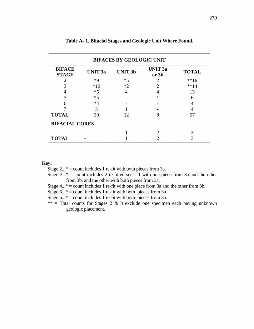
279
Table A- 1. Bifacial Stages and Geologic Unit Where Found.
Key:
Stage 2...* = count includes 1 re-fit with both pieces from 3a. Stage 3...* = count includes 2 re-fitted sets: 1 with one piece from 3a and the other
from 3b, and the other with both pieces from 3a. Stage 4...* = count includes 1 re-fit with one piece from 3a and the other from 3b. Stage 5...* = count includes 1 re-fit with both pieces from 3a. Stage 6...* = count includes 1 re-fit with both pieces from 3a. ** = Total counts for Stages 2 & 3 exclude one specimen each having unknown
geologic placement.
BIFACES BY GEOLOGIC UNIT
BIFACE STAGE UNIT 3a UNIT 3b UNIT 3a
or 3b TOTAL
2 *9 *5 2 **16 3 *10 *2 2 **14 4 *5 4 4 13 5 *5 - 1 6 6 *4 - - 4 7 3 1 - 4
TOTAL 39 12 8 57
BIFACIAL CORES
- 1 2 3 TOTAL - 1 2 3

280
Table A- 2. Overshot Flakes and Geologic Units Where Found.
OVERSHOT FLAKE TYPES BY GEOLOGIC UNIT*
UNIT 3a UNIT 3b UNITS 3a or 3b
TOTAL
FULL OVERSHOT FLAKES
PRIMARY 2 1 - 3 SECONDARY 9 11 - 20 INTERIOR 20 16 3 39 TOTAL 31 28 3 *62
PARTIAL OVERSHOT FLAKES
PRIMARY 13 7 1 21 SECONDARY 32 10 6 48 INTERIOR 29 15 6 50 TOTAL 74 32 13 *119 * = Counts reflect exclusion of 3 specimens having unknown geologic placement.
Table A- 3. Overshot Flake Counts by Overshot and Flake Type.
OVERSHOT FLAKE TOTALS
OVERSHOT TYPE
PRIMARY FLAKE
SECONDARY FLAKE
INTERIOR FLAKE
TOTAL
FULL 3 22 39 64 PARTIAL 20 48 52 121 TOTAL 23 70 91 185
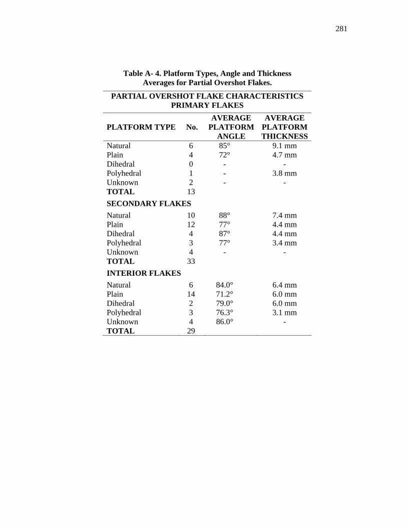
281
Table A- 4. Platform Types, Angle and Thickness Averages for Partial Overshot Flakes.
PARTIAL OVERSHOT FLAKE CHARACTERISTICS PRIMARY FLAKES
PLATFORM TYPE No. AVERAGE
PLATFORM ANGLE
AVERAGE PLATFORM THICKNESS
Natural 6 85° 9.1 mm Plain 4 72° 4.7 mm Dihedral 0 - - Polyhedral 1 - 3.8 mm Unknown 2 - - TOTAL 13 SECONDARY FLAKES Natural 10 88° 7.4 mm Plain 12 77° 4.4 mm Dihedral 4 87° 4.4 mm Polyhedral 3 77° 3.4 mm Unknown 4 - - TOTAL 33 INTERIOR FLAKES Natural 6 84.0° 6.4 mm Plain 14 71.2° 6.0 mm Dihedral 2 79.0° 6.0 mm Polyhedral 3 76.3° 3.1 mm Unknown 4 86.0° - TOTAL 29
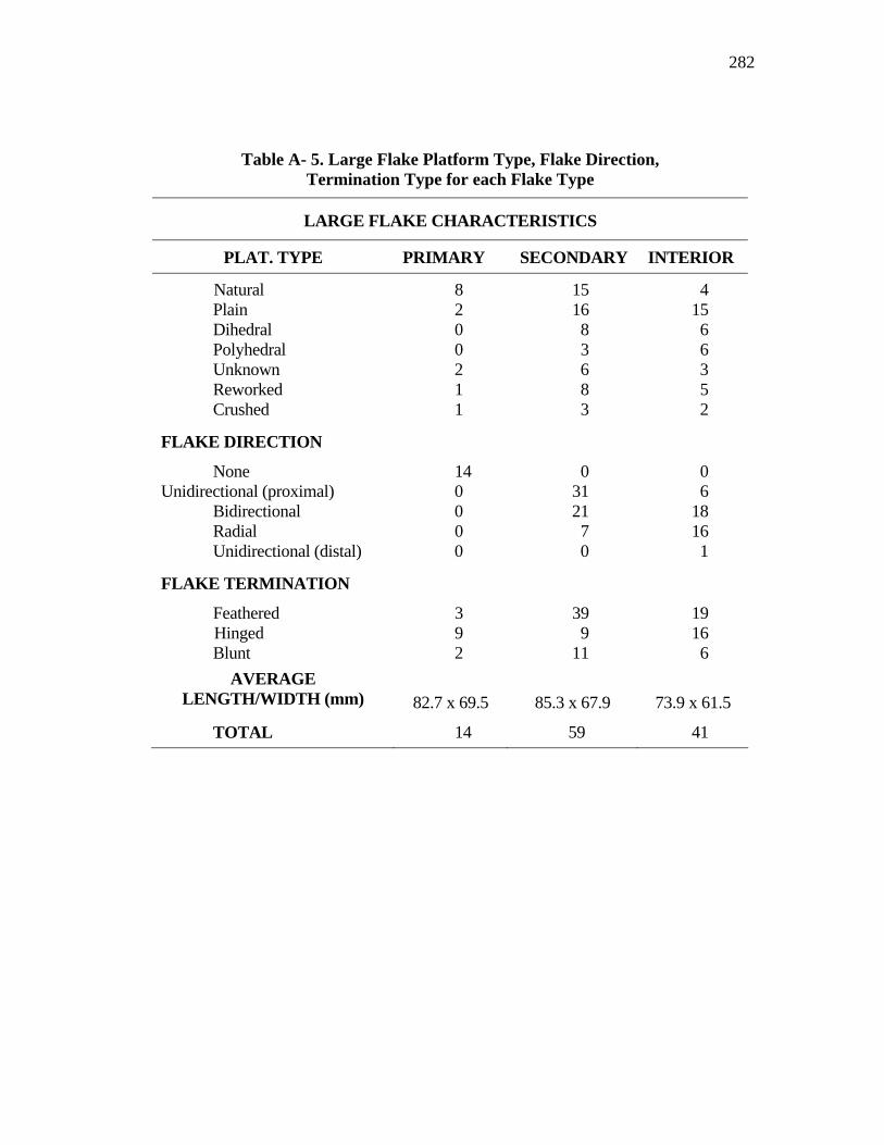
282
Table A- 5. Large Flake Platform Type, Flake Direction, Termination Type for each Flake Type
LARGE FLAKE CHARACTERISTICS
PLAT. TYPE PRIMARY SECONDARY INTERIOR
Natural 8 15 4 Plain 2 16 15 Dihedral 0 8 6 Polyhedral 0 3 6 Unknown 2 6 3 Reworked 1 8 5 Crushed 1 3 2
FLAKE DIRECTION
None 14 0 0 Unidirectional (proximal) 0 31 6
Bidirectional 0 21 18 Radial 0 7 16 Unidirectional (distal) 0 0 1
FLAKE TERMINATION
Feathered 3 39 19 Hinged 9 9 16 Blunt 2 11 6
AVERAGE LENGTH/WIDTH (mm)
82.7 x 69.5
85.3 x 67.9
73.9 x 61.5
TOTAL 14 59 41
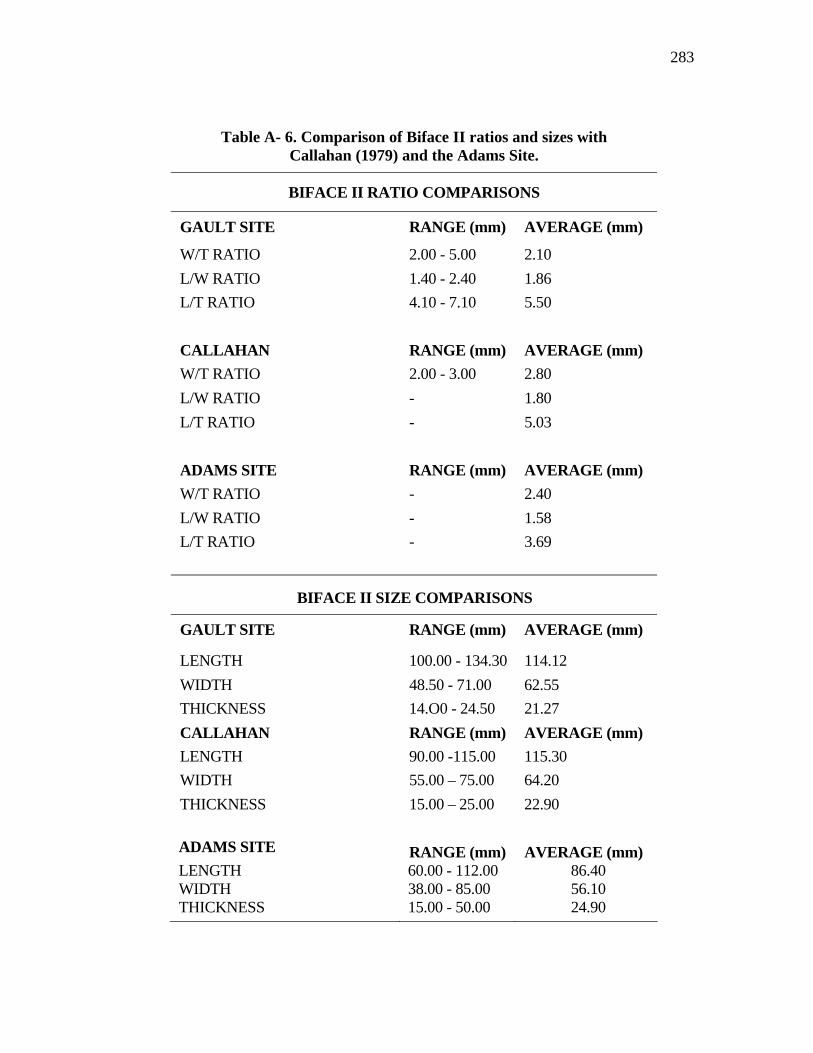
283
Table A- 6. Comparison of Biface II ratios and sizes with Callahan (1979) and the Adams Site.
BIFACE II RATIO COMPARISONS
GAULT SITE RANGE (mm) AVERAGE (mm)
W/T RATIO 2.00 - 5.00 2.10 L/W RATIO 1.40 - 2.40 1.86 L/T RATIO 4.10 - 7.10 5.50 CALLAHAN RANGE (mm) AVERAGE (mm) W/T RATIO 2.00 - 3.00 2.80 L/W RATIO - 1.80 L/T RATIO - 5.03 ADAMS SITE RANGE (mm) AVERAGE (mm) W/T RATIO - 2.40 L/W RATIO - 1.58 L/T RATIO - 3.69
BIFACE II SIZE COMPARISONS
GAULT SITE RANGE (mm) AVERAGE (mm)
LENGTH 100.00 - 134.30 114.12 WIDTH 48.50 - 71.00 62.55 THICKNESS 14.O0 - 24.50 21.27 CALLAHAN RANGE (mm) AVERAGE (mm) LENGTH 90.00 -115.00 115.30 WIDTH 55.00 – 75.00 64.20 THICKNESS 15.00 – 25.00 22.90 ADAMS SITE RANGE (mm) AVERAGE (mm) LENGTH 60.00 - 112.00 86.40 WIDTH 38.00 - 85.00 56.10 THICKNESS 15.00 - 50.00 24.90
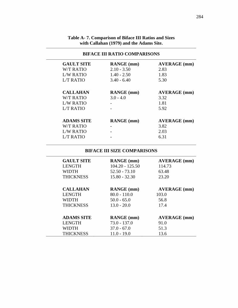
284
Table A- 7. Comparison of Biface III Ratios and Sizes with Callahan (1979) and the Adams Site.
BIFACE III RATIO COMPARISONS
GAULT SITE RANGE (mm) AVERAGE (mm) W/T RATIO 2.10 - 3.50 2.83 L/W RATIO 1.40 - 2.50 1.83 L/T RATIO 3.40 - 6.40 5.30 CALLAHAN RANGE (mm) AVERAGE (mm) W/T RATIO 3.0 - 4.0 3.32 L/W RATIO - 1.81 L/T RATIO - 5.92 ADAMS SITE RANGE (mm) AVERAGE (mm) W/T RATIO - 3.82 L/W RATIO - 2.03 L/T RATIO - 6.31
BIFACE III SIZE COMPARISONS
GAULT SITE RANGE (mm) AVERAGE (mm) LENGTH 104.20 - 125.50 114.73 WIDTH 52.50 - 73.10 63.48 THICKNESS 15.80 - 32.30 23.20 CALLAHAN RANGE (mm) AVERAGE (mm) LENGTH 80.0 - 110.0 103.0 WIDTH 50.0 - 65.0 56.8 THICKNESS 13.0 - 20.0 17.4 ADAMS SITE RANGE (mm) AVERAGE (mm) LENGTH 73.0 - 137.0 91.0 WIDTH 37.0 - 67.0 51.3 THICKNESS 11.0 - 19.0 13.6
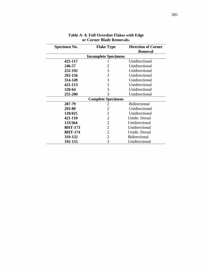
285
Table A- 8. Full Overshot Flakes with Edge or Corner Blade Removals.
Specimen No. Flake Type Direction of Corner Removal
Incomplete Specimens 425-117 1 Unidirectional 246-57 2 Unidirectional 252-192 3 Unidirectional 292-156 3 Unidirectional 314-149 3 Unidirectional 421-113 3 Unidirectional 320-64 3 Unidirectional 255-200 3 Unidirectional
Complete Specimens 287-79 2 Bidirectional 293-80 2 Unidirectional 118/425 2 Unidirectional 421-110 2 Unidir. Dorsal 133/364 2 Unidirectional BHT-173 2 Unidirectional BHT-174 2 Unidir. Dorsal 319-132 2 Bidirectional 192-155 3 Unidirectional
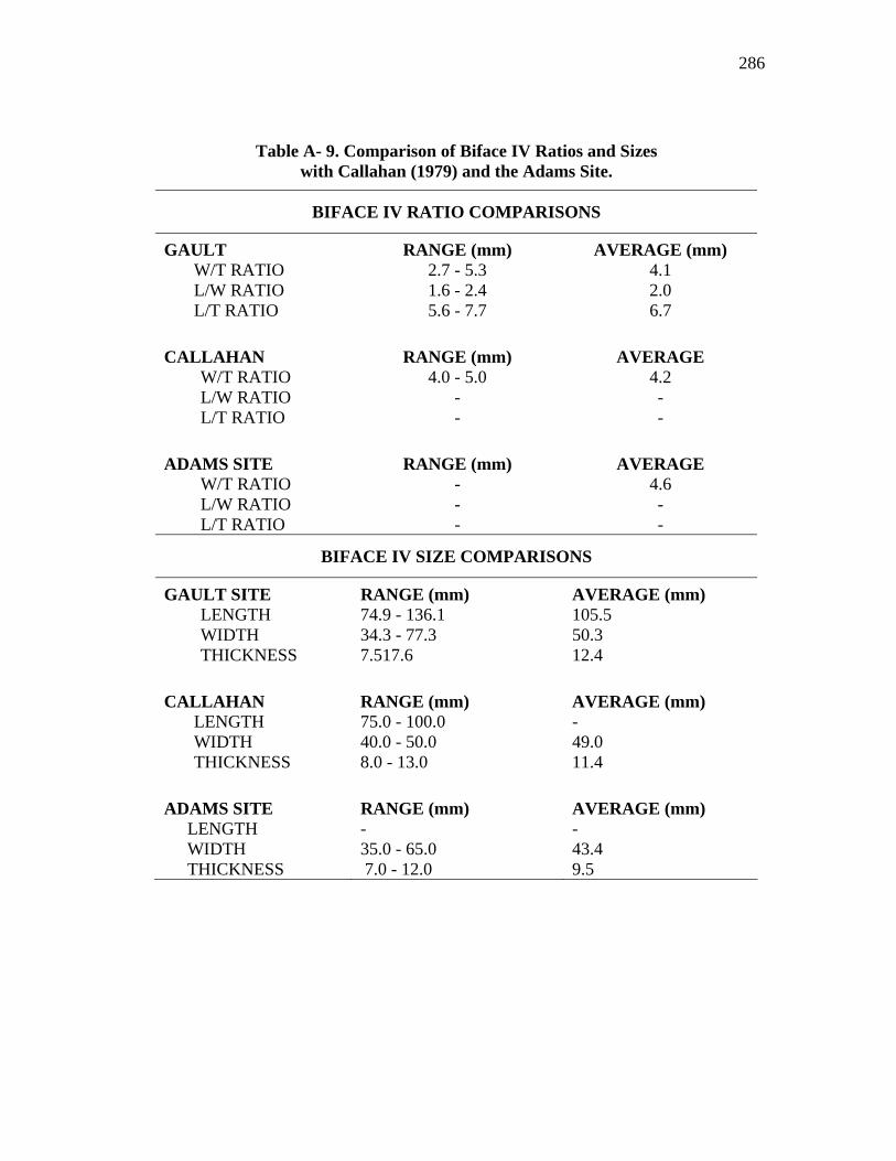
286
Table A- 9. Comparison of Biface IV Ratios and Sizes with Callahan (1979) and the Adams Site.
BIFACE IV RATIO COMPARISONS
GAULT RANGE (mm) AVERAGE (mm) W/T RATIO 2.7 - 5.3 4.1 L/W RATIO 1.6 - 2.4 2.0 L/T RATIO 5.6 - 7.7 6.7
CALLAHAN RANGE (mm) AVERAGE
W/T RATIO 4.0 - 5.0 4.2 L/W RATIO - - L/T RATIO - -
ADAMS SITE RANGE (mm) AVERAGE
W/T RATIO - 4.6 L/W RATIO - - L/T RATIO - -
BIFACE IV SIZE COMPARISONS
GAULT SITE RANGE (mm) AVERAGE (mm) LENGTH 74.9 - 136.1 105.5 WIDTH 34.3 - 77.3 50.3 THICKNESS 7.517.6 12.4
CALLAHAN RANGE (mm) AVERAGE (mm)
LENGTH 75.0 - 100.0 - WIDTH 40.0 - 50.0 49.0 THICKNESS 8.0 - 13.0 11.4
ADAMS SITE RANGE (mm) AVERAGE (mm)
LENGTH - - WIDTH 35.0 - 65.0 43.4 THICKNESS 7.0 - 12.0 9.5
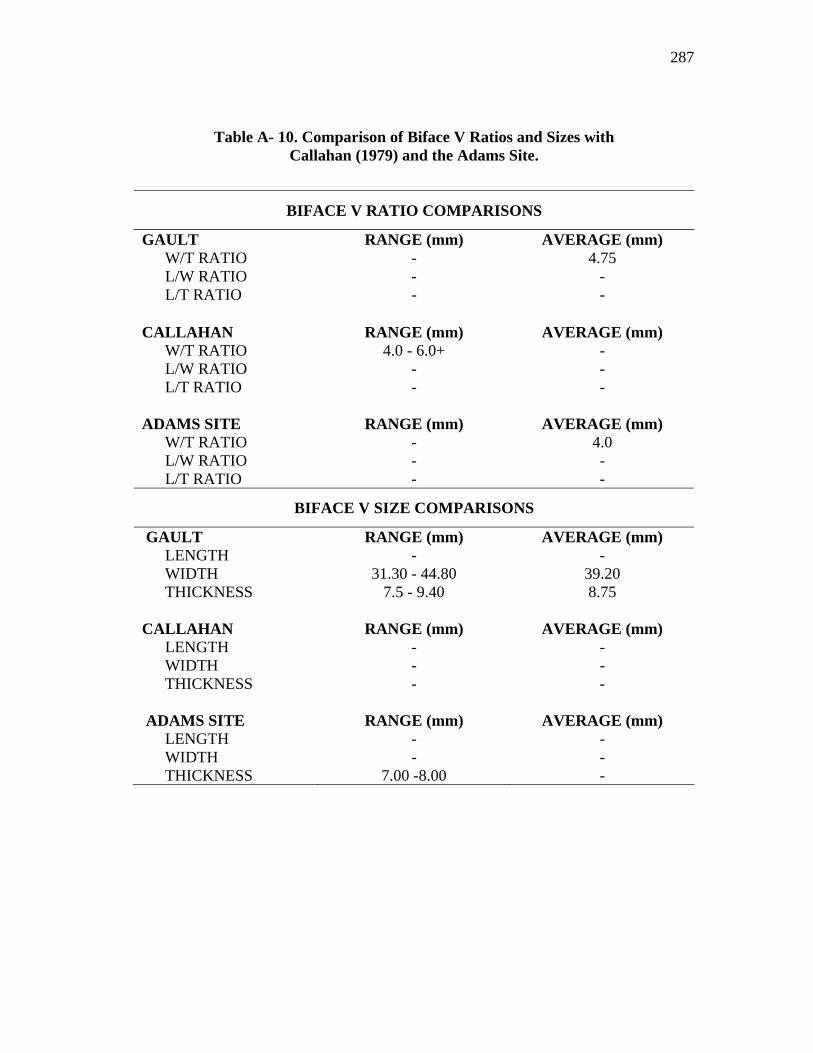
287
Table A- 10. Comparison of Biface V Ratios and Sizes with Callahan (1979) and the Adams Site.
BIFACE V RATIO COMPARISONS
GAULT RANGE (mm) AVERAGE (mm) W/T RATIO - 4.75 L/W RATIO - - L/T RATIO - -
CALLAHAN RANGE (mm) AVERAGE (mm)
W/T RATIO 4.0 - 6.0+ - L/W RATIO - - L/T RATIO - -
ADAMS SITE RANGE (mm) AVERAGE (mm)
W/T RATIO - 4.0 L/W RATIO - - L/T RATIO - -
BIFACE V SIZE COMPARISONS
GAULT RANGE (mm) AVERAGE (mm) LENGTH - - WIDTH 31.30 - 44.80 39.20 THICKNESS 7.5 - 9.40 8.75
CALLAHAN RANGE (mm) AVERAGE (mm)
LENGTH - - WIDTH - - THICKNESS - -
ADAMS SITE RANGE (mm) AVERAGE (mm)
LENGTH - - WIDTH - - THICKNESS 7.00 -8.00 -

288
Table A- 11. Comparisons of Biface VI Ratios and Sizes with the Adams Site.
BIFACE VI RATIO COMPARISONS
GAULT SITE RANGE (mm) AVERAGE (mm)
W/T RATIO 3.60 - 5.9 4.53 L/W RATIO 3.30 3.30 L/T RATIO 14.10 14.10
ADAMS SITE RANGE (mm) AVERAGE (mm) W/T RATIO - 4.60 L/W RATIO - - L/T RATIO - -
BIFACE VI SIZE COMPARISONS
GAULT SITE RANGE (mm) AVERAGE (mm) LENGTH 138.20 138.20 WIDTH 36.40 - 41.60 39.10 THICKNESS 6.70 - 10.20 8.86
ADAMS SITE RANGE (mm) AVERAGE (mm) LENGTH - - WIDTH 29.00 - 48.00 36.10 THICKNESS 7.00 - 10.00 7.90
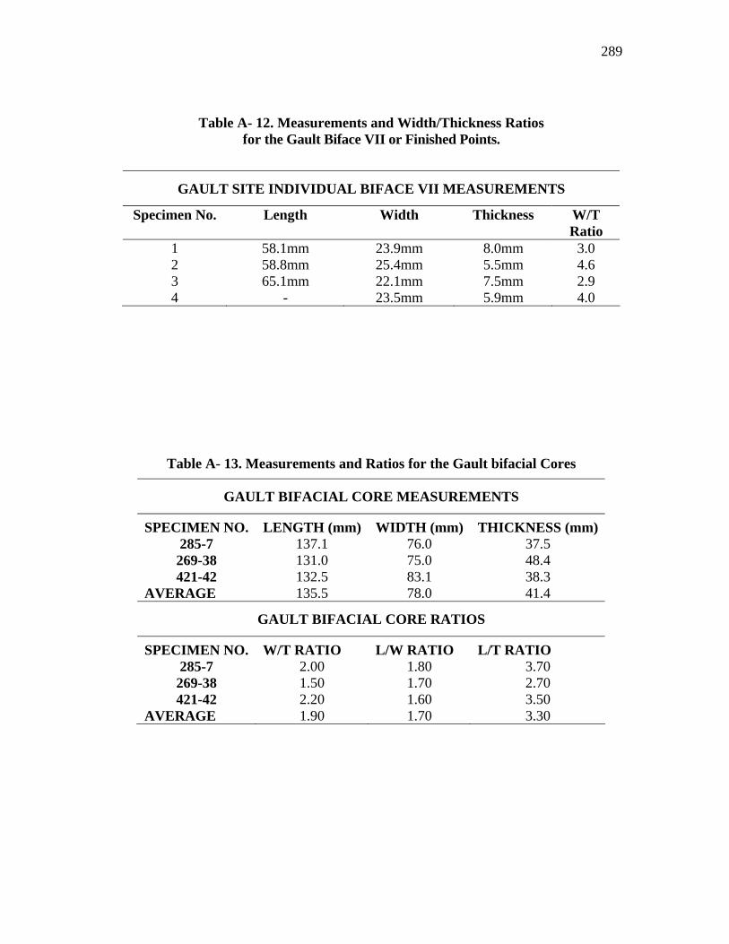
289
Table A- 12. Measurements and Width/Thickness Ratios for the Gault Biface VII or Finished Points.
GAULT SITE INDIVIDUAL BIFACE VII MEASUREMENTS
Specimen No. Length Width Thickness W/T Ratio
1 58.1mm 23.9mm 8.0mm 3.0 2 58.8mm 25.4mm 5.5mm 4.6 3 65.1mm 22.1mm 7.5mm 2.9 4 - 23.5mm 5.9mm 4.0
Table A- 13. Measurements and Ratios for the Gault bifacial Cores
GAULT BIFACIAL CORE MEASUREMENTS
SPECIMEN NO. LENGTH (mm) WIDTH (mm) THICKNESS (mm) 285-7 137.1 76.0 37.5 269-38 131.0 75.0 48.4 421-42 132.5 83.1 38.3
AVERAGE 135.5 78.0 41.4
GAULT BIFACIAL CORE RATIOS
SPECIMEN NO. W/T RATIO L/W RATIO L/T RATIO 285-7 2.00 1.80 3.70 269-38 1.50 1.70 2.70 421-42 2.20 1.60 3.50
AVERAGE 1.90 1.70 3.30
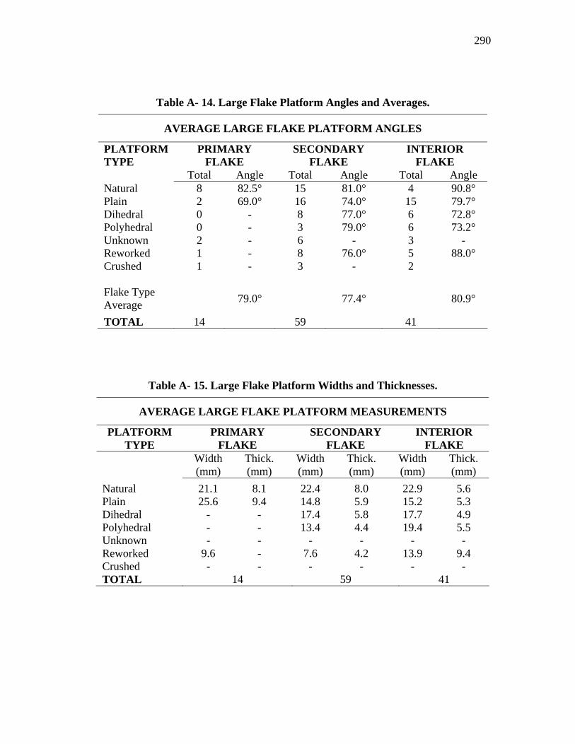
290
Table A- 14. Large Flake Platform Angles and Averages.
AVERAGE LARGE FLAKE PLATFORM ANGLES
PLATFORM TYPE
PRIMARY FLAKE
SECONDARY FLAKE
INTERIOR FLAKE
Total Angle Total Angle Total Angle Natural 8 82.5° 15 81.0° 4 90.8° Plain 2 69.0° 16 74.0° 15 79.7° Dihedral 0 - 8 77.0° 6 72.8° Polyhedral 0 - 3 79.0° 6 73.2° Unknown 2 - 6 - 3 - Reworked 1 - 8 76.0° 5 88.0° Crushed 1 - 3 - 2 Flake Type Average 79.0° 77.4° 80.9°
TOTAL 14 59 41
Table A- 15. Large Flake Platform Widths and Thicknesses.
AVERAGE LARGE FLAKE PLATFORM MEASUREMENTS
PLATFORM TYPE
PRIMARY FLAKE
SECONDARY FLAKE
INTERIOR FLAKE
Width (mm)
Thick. (mm)
Width (mm)
Thick. (mm)
Width (mm)
Thick. (mm)
Natural 21.1 8.1 22.4 8.0 22.9 5.6 Plain 25.6 9.4 14.8 5.9 15.2 5.3 Dihedral - - 17.4 5.8 17.7 4.9 Polyhedral - - 13.4 4.4 19.4 5.5 Unknown - - - - - - Reworked 9.6 - 7.6 4.2 13.9 9.4 Crushed - - - - - - TOTAL 14 59 41
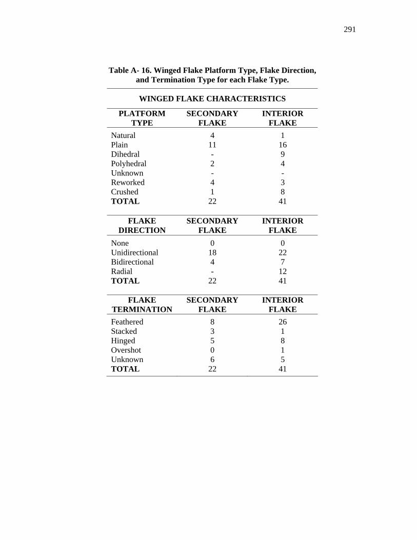
291
Table A- 16. Winged Flake Platform Type, Flake Direction, and Termination Type for each Flake Type.
WINGED FLAKE CHARACTERISTICS
PLATFORM TYPE
SECONDARY FLAKE
INTERIOR FLAKE
Natural 4 1 Plain 11 16 Dihedral - 9 Polyhedral 2 4 Unknown - - Reworked 4 3 Crushed 1 8 TOTAL 22 41
FLAKE DIRECTION
SECONDARY FLAKE
INTERIOR FLAKE
None 0 0 Unidirectional 18 22 Bidirectional 4 7 Radial - 12 TOTAL 22 41
FLAKE TERMINATION
SECONDARY FLAKE
INTERIOR FLAKE
Feathered 8 26 Stacked 3 1 Hinged 5 8 Overshot 0 1 Unknown 6 5 TOTAL 22 41
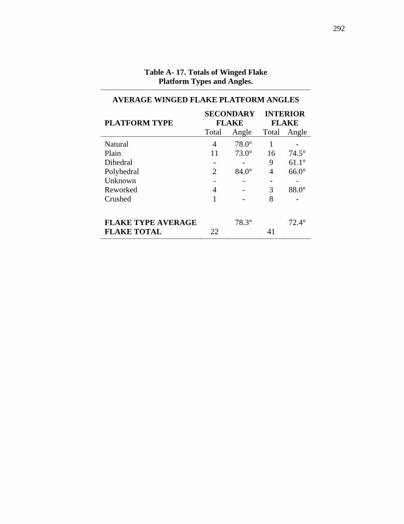
292
Table A- 17. Totals of Winged Flake Platform Types and Angles.
AVERAGE WINGED FLAKE PLATFORM ANGLES
SECONDARY FLAKE
INTERIOR FLAKE PLATFORM TYPE
Total Angle Total Angle Natural 4 78.0° 1 - Plain 11 73.0° 16 74.5° Dihedral - - 9 61.1° Polyhedral 2 84.0° 4 66.0° Unknown - - - - Reworked 4 - 3 88.0° Crushed 1 - 8 - FLAKE TYPE AVERAGE 78.3° 72.4° FLAKE TOTAL 22 41
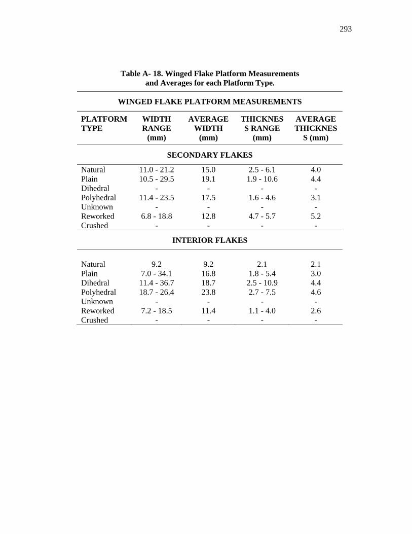
293
Table A- 18. Winged Flake Platform Measurements and Averages for each Platform Type.
WINGED FLAKE PLATFORM MEASUREMENTS
PLATFORM TYPE
WIDTH RANGE
(mm)
AVERAGE WIDTH
(mm)
THICKNESS RANGE
(mm)
AVERAGE THICKNES
S (mm)
SECONDARY FLAKES
Natural 11.0 - 21.2 15.0 2.5 - 6.1 4.0 Plain 10.5 - 29.5 19.1 1.9 - 10.6 4.4 Dihedral - - - - Polyhedral 11.4 - 23.5 17.5 1.6 - 4.6 3.1 Unknown - - - - Reworked 6.8 - 18.8 12.8 4.7 - 5.7 5.2 Crushed - - - -
INTERIOR FLAKES
Natural 9.2 9.2 2.1 2.1 Plain 7.0 - 34.1 16.8 1.8 - 5.4 3.0 Dihedral 11.4 - 36.7 18.7 2.5 - 10.9 4.4 Polyhedral 18.7 - 26.4 23.8 2.7 - 7.5 4.6 Unknown - - - - Reworked 7.2 - 18.5 11.4 1.1 - 4.0 2.6 Crushed - - - -
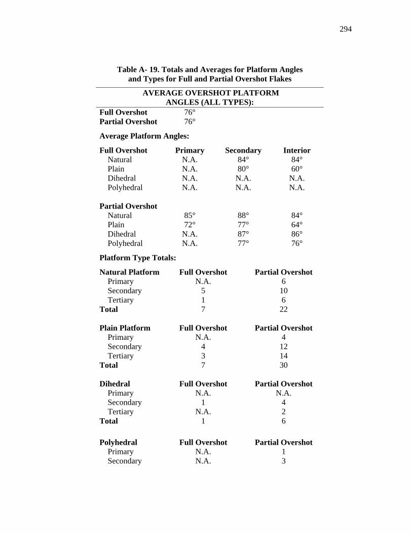
294
Table A- 19. Totals and Averages for Platform Angles and Types for Full and Partial Overshot Flakes
AVERAGE OVERSHOT PLATFORM ANGLES (ALL TYPES):
Full Overshot 76° Partial Overshot 76°
Average Platform Angles:
Full Overshot Primary Secondary Interior Natural N.A. 84° 84° Plain N.A. 80° 60° Dihedral N.A. N.A. N.A. Polyhedral N.A. N.A. N.A.
Partial Overshot
Natural 85° 88° 84° Plain 72° 77° 64° Dihedral N.A. 87° 86° Polyhedral N.A. 77° 76°
Platform Type Totals:
Natural Platform Full Overshot Partial Overshot Primary N.A. 6 Secondary 5 10 Tertiary 1 6
Total 7 22 Plain Platform Full Overshot Partial Overshot
Primary N.A. 4 Secondary 4 12 Tertiary 3 14
Total 7 30 Dihedral Full Overshot Partial Overshot
Primary N.A. N.A. Secondary 1 4 Tertiary N.A. 2
Total 1 6 Polyhedral Full Overshot Partial Overshot
Primary N.A. 1 Secondary N.A. 3
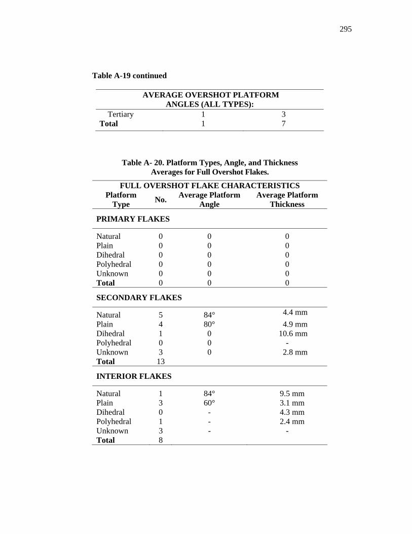
Table A-19 continued
295
AVERAGE OVERSHOT PLATFORM ANGLES (ALL TYPES):
Tertiary 1 3 Total 1 7
Table A- 20. Platform Types, Angle, and Thickness Averages for Full Overshot Flakes.
FULL OVERSHOT FLAKE CHARACTERISTICS Platform
Type No. Average Platform Angle
Average Platform Thickness
PRIMARY FLAKES
Natural 0 0 0 Plain 0 0 0 Dihedral 0 0 0 Polyhedral 0 0 0 Unknown 0 0 0 Total 0 0 0
SECONDARY FLAKES
Natural 5 84° 4.4 mm Plain 4 80° 4.9 mm Dihedral 1 0 10.6 mm Polyhedral 0 0 - Unknown 3 0 2.8 mm Total 13
INTERIOR FLAKES
Natural 1 84° 9.5 mm Plain 3 60° 3.1 mm Dihedral 0 - 4.3 mm Polyhedral 1 - 2.4 mm Unknown 3 - - Total 8
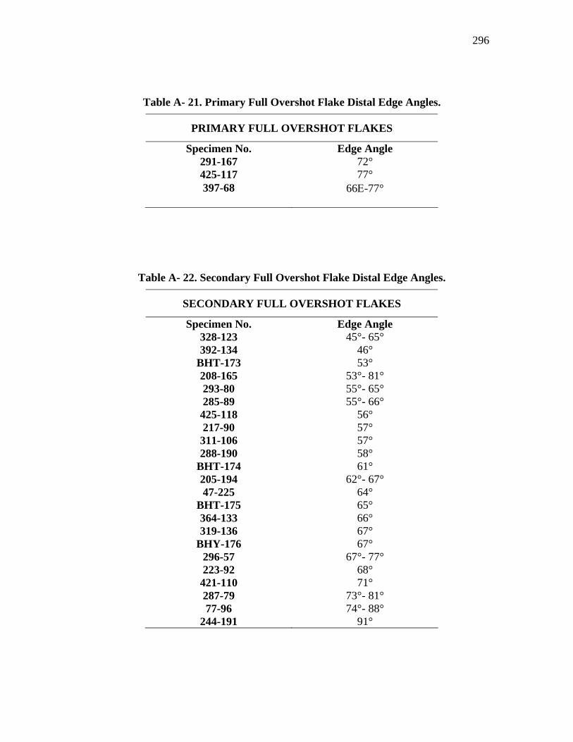
296
Table A- 21. Primary Full Overshot Flake Distal Edge Angles.
PRIMARY FULL OVERSHOT FLAKES
Specimen No. Edge Angle 291-167 72° 425-117 77° 397-68 66Ε-77°
Table A- 22. Secondary Full Overshot Flake Distal Edge Angles.
SECONDARY FULL OVERSHOT FLAKES
Specimen No. Edge Angle 328-123 45°- 65° 392-134 46°
BHT-173 53° 208-165 53°- 81° 293-80 55°- 65° 285-89 55°- 66° 425-118 56° 217-90 57° 311-106 57° 288-190 58°
BHT-174 61° 205-194 62°- 67° 47-225 64°
BHT-175 65° 364-133 66° 319-136 67°
BHY-176 67° 296-57 67°- 77° 223-92 68° 421-110 71° 287-79 73°- 81° 77-96 74°- 88°
244-191 91°
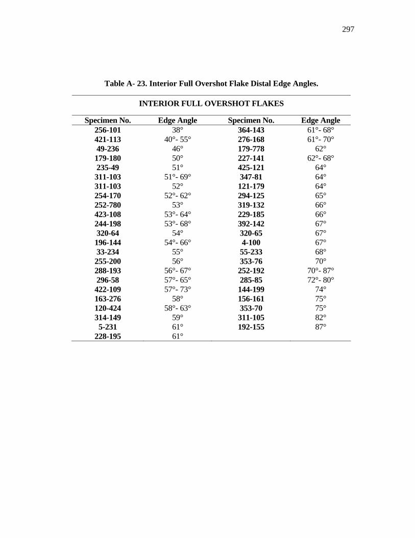
297
Table A- 23. Interior Full Overshot Flake Distal Edge Angles.
INTERIOR FULL OVERSHOT FLAKES
Specimen No. Edge Angle Specimen No. Edge Angle 256-101 38° 364-143 61°- 68° 421-113 40°- 55° 276-168 61°- 70° 49-236 46° 179-778 62° 179-180 50° 227-141 62°- 68° 235-49 51° 425-121 64° 311-103 51°- 69° 347-81 64° 311-103 52° 121-179 64° 254-170 52°- 62° 294-125 65° 252-780 53° 319-132 66° 423-108 53°- 64° 229-185 66° 244-198 53°- 68° 392-142 67° 320-64 54° 320-65 67° 196-144 54°- 66° 4-100 67° 33-234 55° 55-233 68° 255-200 56° 353-76 70° 288-193 56°- 67° 252-192 70°- 87° 296-58 57°- 65° 285-85 72°- 80° 422-109 57°- 73° 144-199 74° 163-276 58° 156-161 75° 120-424 58°- 63° 353-70 75° 314-149 59° 311-105 82° 5-231 61° 192-155 87°
228-195 61°
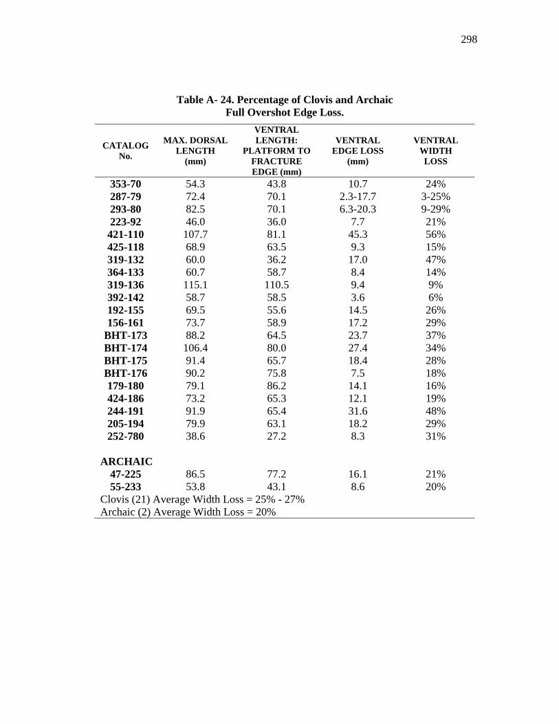
298
Table A- 24. Percentage of Clovis and Archaic Full Overshot Edge Loss.
CATALOG No.
MAX. DORSAL LENGTH
(mm)
VENTRAL LENGTH:
PLATFORM TO FRACTURE EDGE (mm)
VENTRAL EDGE LOSS
(mm)
VENTRAL WIDTH LOSS
353-70 54.3 43.8 10.7 24% 287-79 72.4 70.1 2.3-17.7 3-25% 293-80 82.5 70.1 6.3-20.3 9-29% 223-92 46.0 36.0 7.7 21% 421-110 107.7 81.1 45.3 56% 425-118 68.9 63.5 9.3 15% 319-132 60.0 36.2 17.0 47% 364-133 60.7 58.7 8.4 14% 319-136 115.1 110.5 9.4 9% 392-142 58.7 58.5 3.6 6% 192-155 69.5 55.6 14.5 26% 156-161 73.7 58.9 17.2 29%
BHT-173 88.2 64.5 23.7 37% BHT-174 106.4 80.0 27.4 34% BHT-175 91.4 65.7 18.4 28% BHT-176 90.2 75.8 7.5 18% 179-180 79.1 86.2 14.1 16% 424-186 73.2 65.3 12.1 19% 244-191 91.9 65.4 31.6 48% 205-194 79.9 63.1 18.2 29% 252-780 38.6 27.2 8.3 31%
ARCHAIC
47-225 86.5 77.2 16.1 21% 55-233 53.8 43.1 8.6 20%
Clovis (21) Average Width Loss = 25% - 27% Archaic (2) Average Width Loss = 20%

299
APPENDIX B
BLADE TABLES
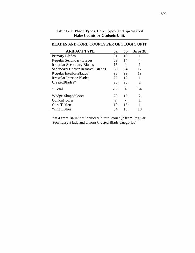
300
Table B- 1. Blade Types, Core Types, and Specialized Flake Counts by Geologic Unit.
BLADES AND CORE COUNTS PER GEOLOGIC UNIT
ARIFACT TYPE 3a 3b 3a or 3b Primary Blades 21 15 1 Regular Secondary Blades 39 14 4 Irregular Secondary Blades 15 9 1 Secondary Corner Removal Blades 65 34 12 Regular Interior Blades* 89 38 13 Irregular Interior Blades 29 12 1 CrestedBlades* 28 23 2
* Total 285 145 34
Wedge-ShapedCores 29 16 2 Conical Cores 2 - 1 Core Tablets 19 16 1 Wing Flakes 34 19 10
* = 4 from Baulk not included in total count (2 from Regular Secondary Blade and 2 from Crested Blade categories)
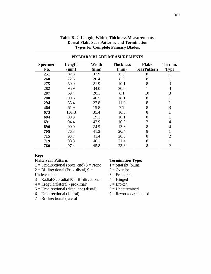
301
Table B- 2. Length, Width, Thickness Measurements, Dorsal Flake Scar Patterns, and Termination
Types for Complete Primary Blades.
PRIMARY BLADE MEASUREMENTS
Specimen No.
Length (mm)
Width (mm)
Thickness (mm)
Flake ScarPattern
Termin. Type
251 82.3 32.9 6.3 8 1 268 72.3 20.4 8.3 8 1 275 50.9 21.9 10.1 8 3 282 95.9 34.0 20.8 1 3 287 69.4 28.1 6.1 10 3 288 90.6 40.5 18.1 8 1 294 55.4 22.8 11.6 8 1 464 61.9 19.8 7.7 8 3 673 101.3 35.4 10.6 8 1 684 80.3 19.1 10.1 8 1 691 94.4 42.9 10.6 2 4 696 90.0 24.9 13.3 8 4 705 76.3 41.3 20.4 8 1 715 93.7 41.4 20.8 8 2 719 98.8 40.1 21.4 8 1 760 97.4 45.8 23.8 8 2
Key: Flake Scar Pattern: Termination Type: 1 = Unidirectional (prox. end) 8 = None 2 = Bi-directional (Prox-distal) 9 = Undetermined 3 = Radial/Subradial10 = Bi-directional 4 = Irregular(lateral - proximal/ 5 = Unidirectional (distal end) distal) 6 = Unidirectional (lateral) 7 = Bi-directional (lateral
1 = Straight (blunt) 2 = Overshot 3 = Feathered 4 = Hinged 5 = Broken 6 = Undetermined 7 = Reworked/retouched
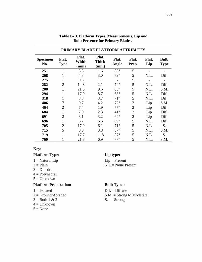
302
Table B- 3. Platform Types, Measurements, Lip and Bulb Presence for Primary Blades.
PRIMARY BLADE PLATFORM ATTRIBUTES
Specimen No.
Plat. Type
Plat. Width (mm)
Plat. Thick (mm)
Plat. Angle
Plat. Prep.
Plat. Lip
Bulb Type
251 1 3.3 1.6 83° 5 - - 268 1 4.8 3.0 79° 5 N.L. Dif. 275 1 9.3 1.7 - 5 - - 282 2 14.3 2.1 74° 5 N.L. Dif. 288 1 21.5 9.6 83° 5 N.L. S.M. 294 1 17.0 8.7 63° 5 N.L. Dif. 318 1 8.8 3.7 71° 5 N.L. Dif. 406 7 9.7 4.2 72° 2 Lip S.M. 464 2 7.4 1.9 77° 2 Lip Dif. 684 1 7.0 2.3 41° 2 Lip Dif. 691 2 8.1 3.2 64° 2 Lip Dif. 696 1 6.7 6.6 89° 5 N.L. Dif. 705 2 17.9 6.1 71° 5 N.L. S. 715 5 8.8 3.8 87° 5 N.L. S.M. 719 1 17.7 11.8 87° 5 N.L. S. 760 1 21.7 6.9 77° 5 N.L. S.M.
Key: Platform Type: Lip type: 1 = Natural Lip 2 = Plain 3 = Dihedral 4 = Polyhedral 5 = Unknown
Lip = Present N.L.= None Present
Platform Preparation: Bulb Type : 1 = Isolated 2 = Ground/Abraded 3 = Both 1 & 2 4 = Unknown 5 = None
Dif. = Diffuse S.M. = Strong to Moderate S. = Strong
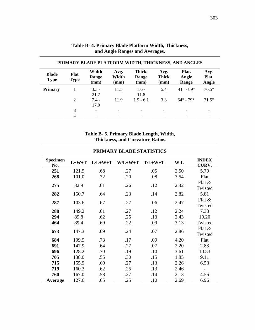
303
Table B- 4. Primary Blade Platform Width, Thickness, and Angle Ranges and Averages.
PRIMARY BLADE PLATFORM WIDTH, THICKNESS, AND ANGLES
Blade Type
Plat Type
Width Range (mm)
Avg. Width (mm)
Thick. Range (mm)
Avg. Thick (mm)
Plat. Angle Range
Avg. Plat.
Angle Primary 1 3.3 -
21.7 11.5 1.6 -
11.8 5.4 41° - 89° 76.5°
2 7.4 - 17.9
11.9 1.9 - 6.1 3.3 64° - 79° 71.5°
3 - - - - - - 4 - - - - - -
Table B- 5. Primary Blade Length, Width, Thickness, and Curvature Ratios.
PRIMARY BLADE STATISTICS
Specimen No. L+W+T L/L+W+T W/L+W+T T/L+W+T W:L INDEX
CURV. 251 121.5 .68 .27 .05 2.50 5.70 268 101.0 .72 .20 .08 3.54 Flat
275 82.9 .61 .26 .12 2.32 Flat & Twisted
282 150.7 .64 .23 .14 2.82 5.81
287 103.6 .67 .27 .06 2.47 Flat & Twisted
288 149.2 .61 .27 .12 2.24 7.33 294 89.8 .62 .25 .13 2.43 10.20 464 89.4 .69 .22 .09 3.13 Twisted
673 147.3 .69 .24 .07 2.86 Flat & Twisted
684 109.5 .73 .17 .09 4.20 Flat 691 147.9 .64 .27 .07 2.20 2.83 696 128.2 .70 .19 .10 3.61 10.53 705 138.0 .55 .30 .15 1.85 9.11 715 155.9 .60 .27 .13 2.26 6.58 719 160.3 .62 .25 .13 2.46 - 760 167.0 .58 .27 .14 2.13 4.56
Average 127.6 .65 .25 .10 2.69 6.96
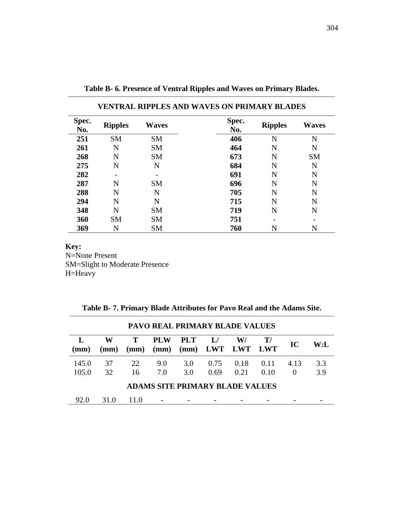
304
Table B- 6. Presence of Ventral Ripples and Waves on Primary Blades.
VENTRAL RIPPLES AND WAVES ON PRIMARY BLADES
Spec. No. Ripples Waves Spec.
No. Ripples Waves
251 SM SM 406 N N 261 N SM 464 N N 268 N SM 673 N SM 275 N N 684 N N 282 - - 691 N N 287 N SM 696 N N 288 N N 705 N N 294 N N 715 N N 348 N SM 719 N N 360 SM SM 751 - - 369 N SM 760 N N
Key: N=None Present SM=Slight to Moderate Presence H=Heavy
Table B- 7. Primary Blade Attributes for Pavo Real and the Adams Site.
PAVO REAL PRIMARY BLADE VALUES
L (mm)
W (mm)
T (mm)
PLW (mm)
PLT (mm)
L/ LWT
W/ LWT
T/ LWT IC W:L
145.0 37 22 9.0 3.0 0.75 0.18 0.11 4.13 3.3 105.0 32 16 7.0 3.0 0.69 0.21 0.10 0 3.9
ADAMS SITE PRIMARY BLADE VALUES
92.0 31.0 11.0 - - - - - - -
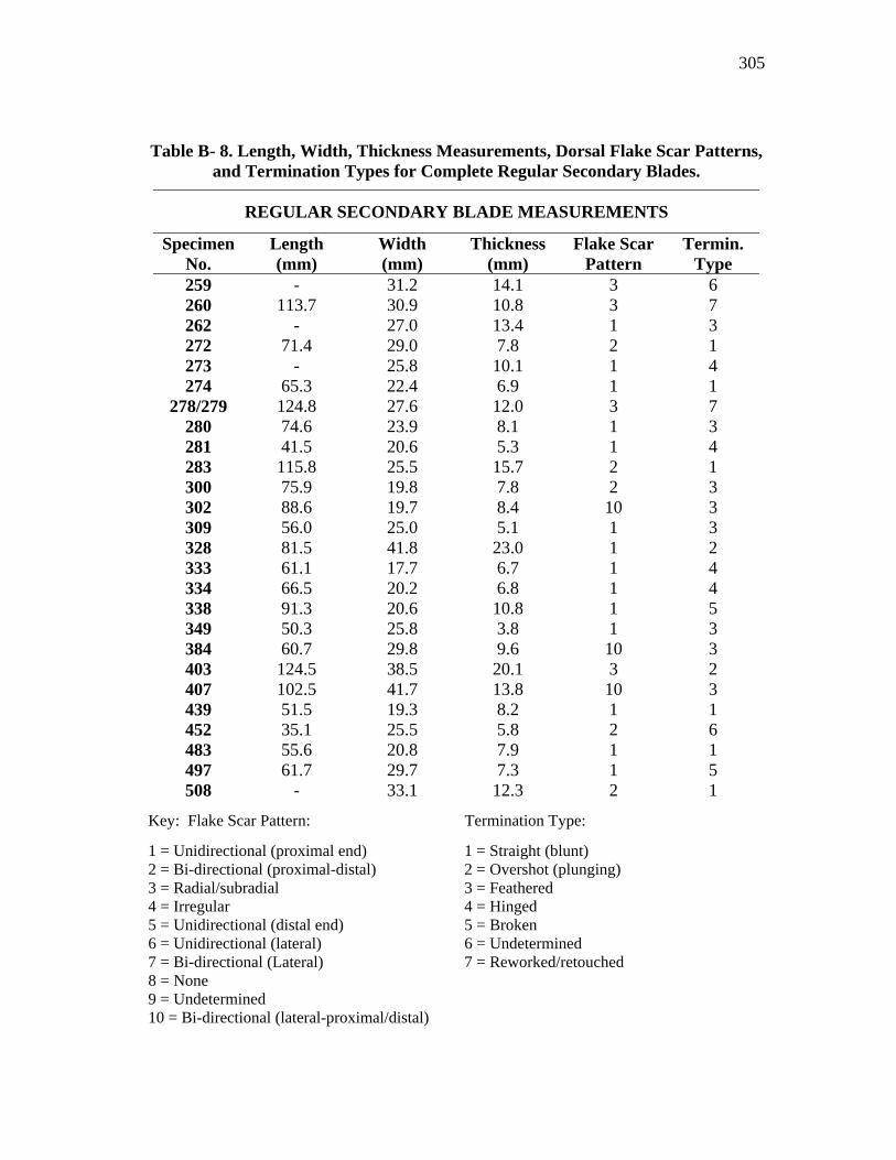
305
Key: Flake Scar Pattern: Termination Type:
1 = Unidirectional (proximal end) 2 = Bi-directional (proximal-distal) 3 = Radial/subradial 4 = Irregular 5 = Unidirectional (distal end) 6 = Unidirectional (lateral) 7 = Bi-directional (Lateral) 8 = None 9 = Undetermined 10 = Bi-directional (lateral-proximal/distal)
1 = Straight (blunt) 2 = Overshot (plunging) 3 = Feathered 4 = Hinged 5 = Broken 6 = Undetermined 7 = Reworked/retouched
Table B- 8. Length, Width, Thickness Measurements, Dorsal Flake Scar Patterns, and Termination Types for Complete Regular Secondary Blades.
REGULAR SECONDARY BLADE MEASUREMENTS
Specimen No.
Length (mm)
Width (mm)
Thickness (mm)
Flake Scar Pattern
Termin. Type
259 - 31.2 14.1 3 6 260 113.7 30.9 10.8 3 7 262 - 27.0 13.4 1 3 272 71.4 29.0 7.8 2 1 273 - 25.8 10.1 1 4 274 65.3 22.4 6.9 1 1
278/279 124.8 27.6 12.0 3 7 280 74.6 23.9 8.1 1 3 281 41.5 20.6 5.3 1 4 283 115.8 25.5 15.7 2 1 300 75.9 19.8 7.8 2 3 302 88.6 19.7 8.4 10 3 309 56.0 25.0 5.1 1 3 328 81.5 41.8 23.0 1 2 333 61.1 17.7 6.7 1 4 334 66.5 20.2 6.8 1 4 338 91.3 20.6 10.8 1 5 349 50.3 25.8 3.8 1 3 384 60.7 29.8 9.6 10 3 403 124.5 38.5 20.1 3 2 407 102.5 41.7 13.8 10 3 439 51.5 19.3 8.2 1 1 452 35.1 25.5 5.8 2 6 483 55.6 20.8 7.9 1 1 497 61.7 29.7 7.3 1 5 508 - 33.1 12.3 2 1
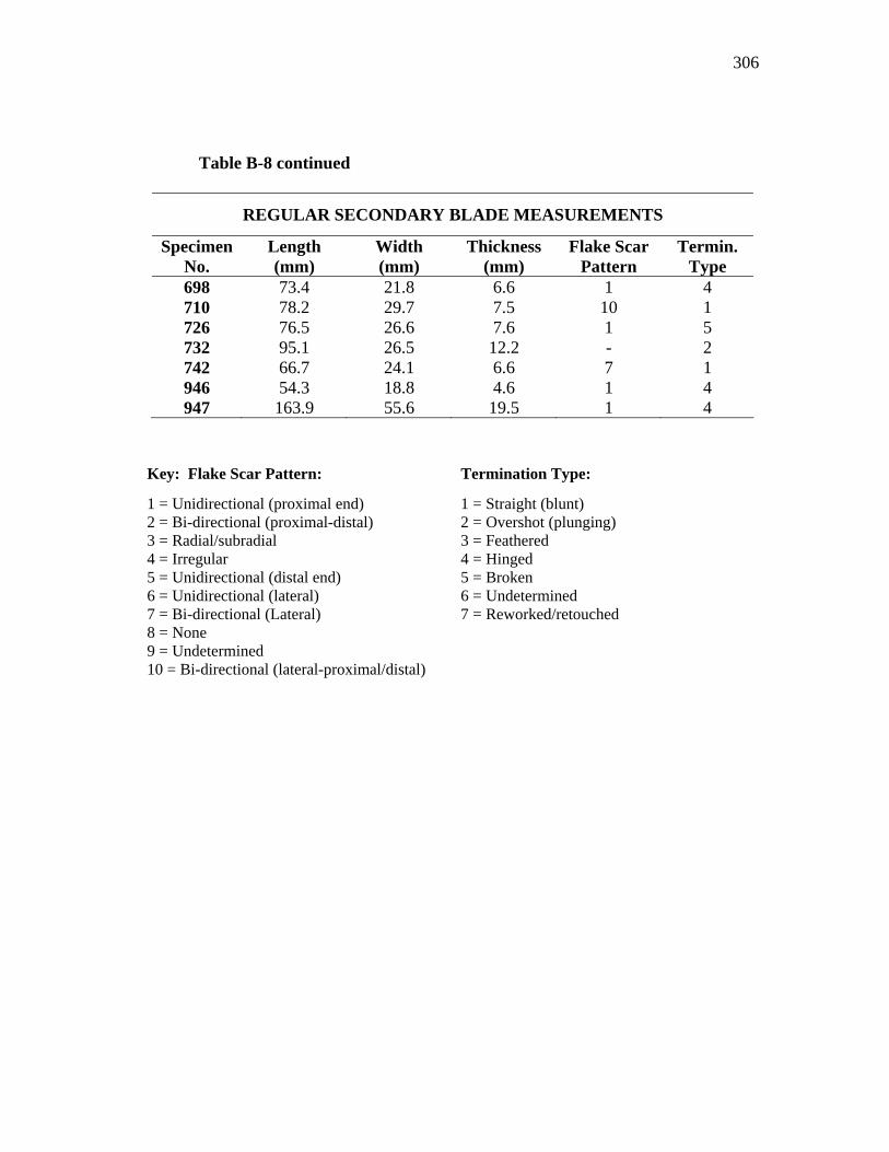
306
Table B-8 continued
REGULAR SECONDARY BLADE MEASUREMENTS
Specimen No.
Length (mm)
Width (mm)
Thickness (mm)
Flake Scar Pattern
Termin. Type
698 73.4 21.8 6.6 1 4 710 78.2 29.7 7.5 10 1 726 76.5 26.6 7.6 1 5 732 95.1 26.5 12.2 - 2 742 66.7 24.1 6.6 7 1 946 54.3 18.8 4.6 1 4 947 163.9 55.6 19.5 1 4
Key: Flake Scar Pattern: Termination Type:
1 = Unidirectional (proximal end) 2 = Bi-directional (proximal-distal) 3 = Radial/subradial 4 = Irregular 5 = Unidirectional (distal end) 6 = Unidirectional (lateral) 7 = Bi-directional (Lateral) 8 = None 9 = Undetermined 10 = Bi-directional (lateral-proximal/distal)
1 = Straight (blunt) 2 = Overshot (plunging) 3 = Feathered 4 = Hinged 5 = Broken 6 = Undetermined 7 = Reworked/retouched
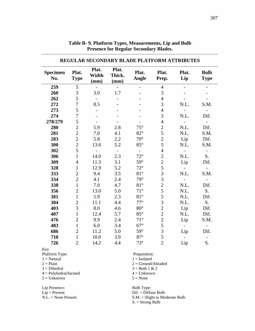
307
Key Platform Type: Preparation: 1 = Natural 1 = Isolated 2 = Plain 2 = Ground/Abraded 3 = Dihedral 3 = Both 1 & 2 4 = Polyhedral/faceted 4 = Unknown 5 = Unknown 5 = None Lip Presence: Bulb Type: Lip = Present Dif. = Diffuse Bulb N.L. = None Present S.M. = Slight to Moderate Bulb S. = Strong Bulb
Table B- 9. Platform Types, Measurements, Lip and Bulb Presence for Regular Secondary Blades.
REGULAR SECONDARY BLADE PLATFORM ATTRIBUTES
Specimen No.
Plat. Type
Plat. Width (mm)
Plat. Thick. (mm)
Plat. Angle
Plat. Prep.
Plat. Lip
Bulb Type
259 5 - - - 4 - - 260 3 3.0 1.7 - 3 - - 262 5 - - - 4 - - 272 7 8.5 - - 3 N.L. S.M. 273 5 - - - 4 - - 274 7 - - - 3 N.L. Dif.
278/279 5 - - - 4 - - 280 2 5.9 2.8 75° 2 N.L. Dif. 281 2 7.0 4.1 82° 5 N.L. S.M. 283 2 5.8 2.2 70° 2 Lip Dif. 300 2 13.6 5.2 85° 5 N.L. S.M. 302 5 - - - 4 - - 306 1 14.0 2.3 72° 2 N.L. S. 309 4 11.3 3.1 59° 2 Lip Dif. 328 1 12.9 5.2 72° 5 - - 333 2 9.4 3.5 81° 3 N.L. S.M. 334 2 4.1 2.4 79° 3 - - 338 1 7.0 4.7 81° 2 N.L. Dif. 356 2 13.0 5.0 71° 5 N.L. S. 381 1 5.9 2.3 81° 5 N.L. Dif. 384 2 11.1 4.4 77° 3 N.L. S. 403 3 8.0 4.6 80° 2 Lip Dif. 407 1 12.4 5.7 85° 2 N.L. Dif. 476 2 9.9 2.4 71° 2 Lip S.M. 483 1 6.0 3.4 67° 5 - - 686 2 11.2 5.0 59° 3 Lip Dif. 710 1 10.0 3.9 87° 5 - - 726 2 14.2 4.4 73° 2 Lip S.
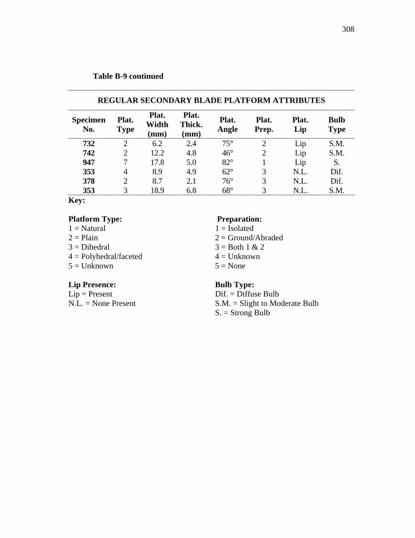
308
Table B-9 continued
REGULAR SECONDARY BLADE PLATFORM ATTRIBUTES
Specimen No.
Plat. Type
Plat. Width (mm)
Plat. Thick. (mm)
Plat. Angle
Plat. Prep.
Plat. Lip
Bulb Type
732 2 6.2 2.4 75° 2 Lip S.M. 742 2 12.2 4.8 46° 2 Lip S.M. 947 7 17.8 5.0 82° 1 Lip S. 353 4 8.9 4.9 62° 3 N.L. Dif. 378 2 8.7 2.1 76° 3 N.L. Dif. 353 3 18.9 6.8 68° 3 N.L. S.M.
Key: Platform Type: Preparation: 1 = Natural 1 = Isolated 2 = Plain 2 = Ground/Abraded 3 = Dihedral 3 = Both 1 & 2 4 = Polyhedral/faceted 4 = Unknown 5 = Unknown 5 = None Lip Presence: Bulb Type: Lip = Present Dif. = Diffuse Bulb N.L. = None Present S.M. = Slight to Moderate Bulb S. = Strong Bulb
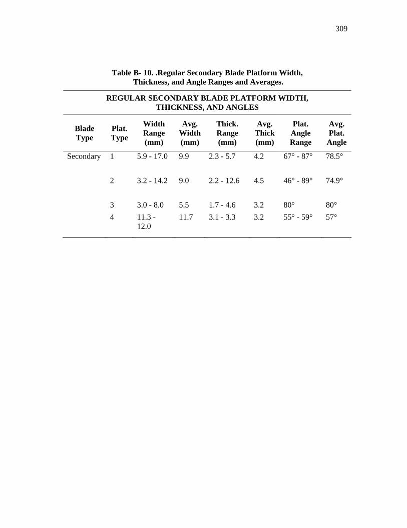
309
Table B- 10. .Regular Secondary Blade Platform Width, Thickness, and Angle Ranges and Averages.
REGULAR SECONDARY BLADE PLATFORM WIDTH, THICKNESS, AND ANGLES
Blade Type
Plat. Type
Width Range (mm)
Avg. Width (mm)
Thick. Range (mm)
Avg. Thick (mm)
Plat. Angle Range
Avg. Plat.
Angle
Secondary 1 5.9 - 17.0 9.9 2.3 - 5.7 4.2 67° - 87° 78.5°
2 3.2 - 14.2 9.0 2.2 - 12.6 4.5 46° - 89° 74.9°
3 3.0 - 8.0 5.5 1.7 - 4.6 3.2 80° 80° 4 11.3 -
12.0 11.7 3.1 - 3.3 3.2 55° - 59° 57°
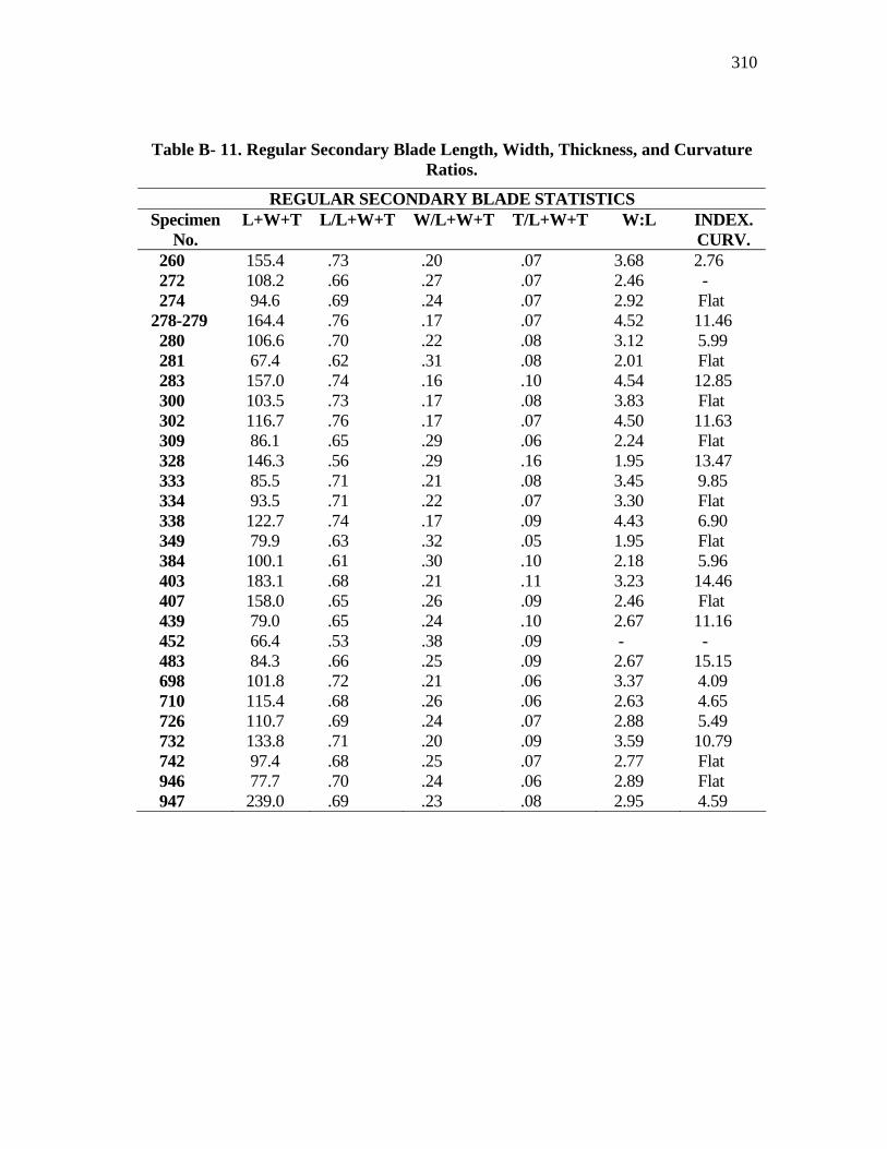
310
Table B- 11. Regular Secondary Blade Length, Width, Thickness, and Curvature Ratios.
REGULAR SECONDARY BLADE STATISTICS Specimen
No. L+W+T L/L+W+T W/L+W+T T/L+W+T W:L INDEX.
CURV. 260 155.4 .73 .20 .07 3.68 2.76 272 108.2 .66 .27 .07 2.46 - 274 94.6 .69 .24 .07 2.92 Flat 278-279 164.4 .76 .17 .07 4.52 11.46 280 106.6 .70 .22 .08 3.12 5.99 281 67.4 .62 .31 .08 2.01 Flat 283 157.0 .74 .16 .10 4.54 12.85 300 103.5 .73 .17 .08 3.83 Flat 302 116.7 .76 .17 .07 4.50 11.63 309 86.1 .65 .29 .06 2.24 Flat 328 146.3 .56 .29 .16 1.95 13.47 333 85.5 .71 .21 .08 3.45 9.85 334 93.5 .71 .22 .07 3.30 Flat 338 122.7 .74 .17 .09 4.43 6.90 349 79.9 .63 .32 .05 1.95 Flat 384 100.1 .61 .30 .10 2.18 5.96 403 183.1 .68 .21 .11 3.23 14.46 407 158.0 .65 .26 .09 2.46 Flat 439 79.0 .65 .24 .10 2.67 11.16 452 66.4 .53 .38 .09 - - 483 84.3 .66 .25 .09 2.67 15.15 698 101.8 .72 .21 .06 3.37 4.09 710 115.4 .68 .26 .06 2.63 4.65 726 110.7 .69 .24 .07 2.88 5.49 732 133.8 .71 .20 .09 3.59 10.79 742 97.4 .68 .25 .07 2.77 Flat 946 77.7 .70 .24 .06 2.89 Flat 947 239.0 .69 .23 .08 2.95 4.59
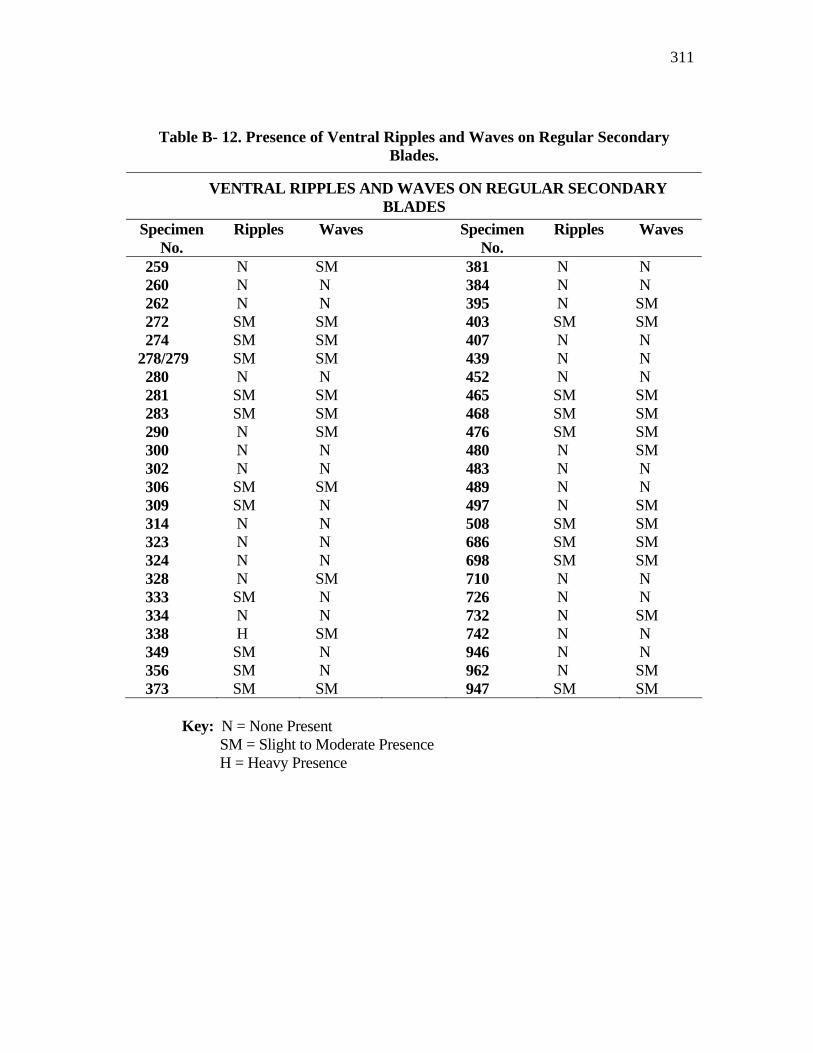
311
Table B- 12. Presence of Ventral Ripples and Waves on Regular Secondary Blades.
VENTRAL RIPPLES AND WAVES ON REGULAR SECONDARY BLADES
Specimen No.
Ripples Waves Specimen No.
Ripples Waves
259 N SM 381 N N 260 N N 384 N N 262 N N 395 N SM 272 SM SM 403 SM SM 274 SM SM 407 N N 278/279 SM SM 439 N N 280 N N 452 N N 281 SM SM 465 SM SM 283 SM SM 468 SM SM 290 N SM 476 SM SM 300 N N 480 N SM 302 N N 483 N N 306 SM SM 489 N N 309 SM N 497 N SM 314 N N 508 SM SM 323 N N 686 SM SM 324 N N 698 SM SM 328 N SM 710 N N 333 SM N 726 N N 334 N N 732 N SM 338 H SM 742 N N 349 SM N 946 N N 356 SM N 962 N SM 373 SM SM 947 SM SM
Key: N = None Present SM = Slight to Moderate Presence H = Heavy Presence
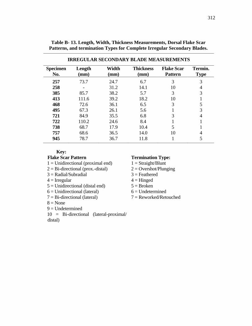
312
Table B- 13. Length, Width, Thickness Measurements, Dorsal Flake Scar Patterns, and termination Types for Complete Irregular Secondary Blades.
IRREGULAR SECONDARY BLADE MEASUREMENTS
Specimen No.
Length (mm)
Width (mm)
Thickness (mm)
Flake Scar Pattern
Termin. Type
257 73.7 24.7 6.7 3 3 258 - 31.2 14.1 10 4 385 85.7 38.2 5.7 3 3 413 111.6 39.2 18.2 10 1 468 72.6 36.1 6.5 3 5 495 67.3 26.1 5.6 1 3 721 84.9 35.5 6.8 3 4 722 110.2 24.6 8.4 1 1 738 68.7 17.9 10.4 5 1 757 68.6 36.5 14.0 10 4 945 78.7 36.7 11.8 1 5
Key:
Flake Scar Pattern Termination Type: 1 = Unidirectional (proximal end) 2 = Bi-directional (prox.-distal) 3 = Radial/Subradial 4 = Irregular 5 = Unidirectional (distal end) 6 = Unidirectional (lateral) 7 = Bi-directional (lateral) 8 = None 9 = Undetermined 10 = Bi-directional (lateral-proximal/ distal)
1 = Straight/Blunt 2 = Overshot/Plunging 3 = Feathered 4 = Hinged 5 = Broken 6 = Undetermined 7 = Reworked/Retouched
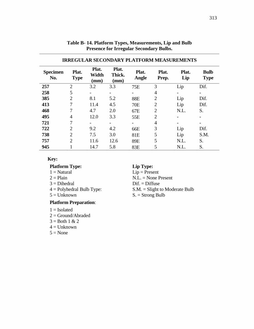
313
Table B- 14. Platform Types, Measurements, Lip and Bulb Presence for Irregular Secondary Bulbs.
IRREGULAR SECONDARY PLATFORM MEASUREMENTS
Specimen No.
Plat. Type
Plat. Width (mm)
Plat. Thick. (mm)
Plat. Angle
Plat. Prep.
Plat. Lip
Bulb Type
257 2 3.2 3.3 75Ε 3 Lip Dif. 258 5 - - - 4 - - 385 2 8.1 5.2 88Ε 2 Lip Dif. 413 7 11.4 4.5 70Ε 2 Lip Dif. 468 7 4.7 2.0 67Ε 2 N.L. S. 495 4 12.0 3.3 55Ε 2 - - 721 7 - - - 4 - - 722 2 9.2 4.2 66Ε 3 Lip Dif. 738 2 7.5 3.0 81Ε 5 Lip S.M. 757 2 11.6 12.6 89Ε 5 N.L. S. 945 1 14.7 5.8 83Ε 5 N.L. S.
Key: Platform Type: Lip Type: 1 = Natural 2 = Plain 3 = Dihedral 4 = Polyhedral Bulb Type: 5 = Unknown
Lip = Present N.L. = None Present Dif. = Diffuse S.M. = Slight to Moderate Bulb S. = Strong Bulb
Platform Preparation: 1 = Isolated 2 = Ground/Abraded 3 = Both 1 & 2 4 = Unknown 5 = None
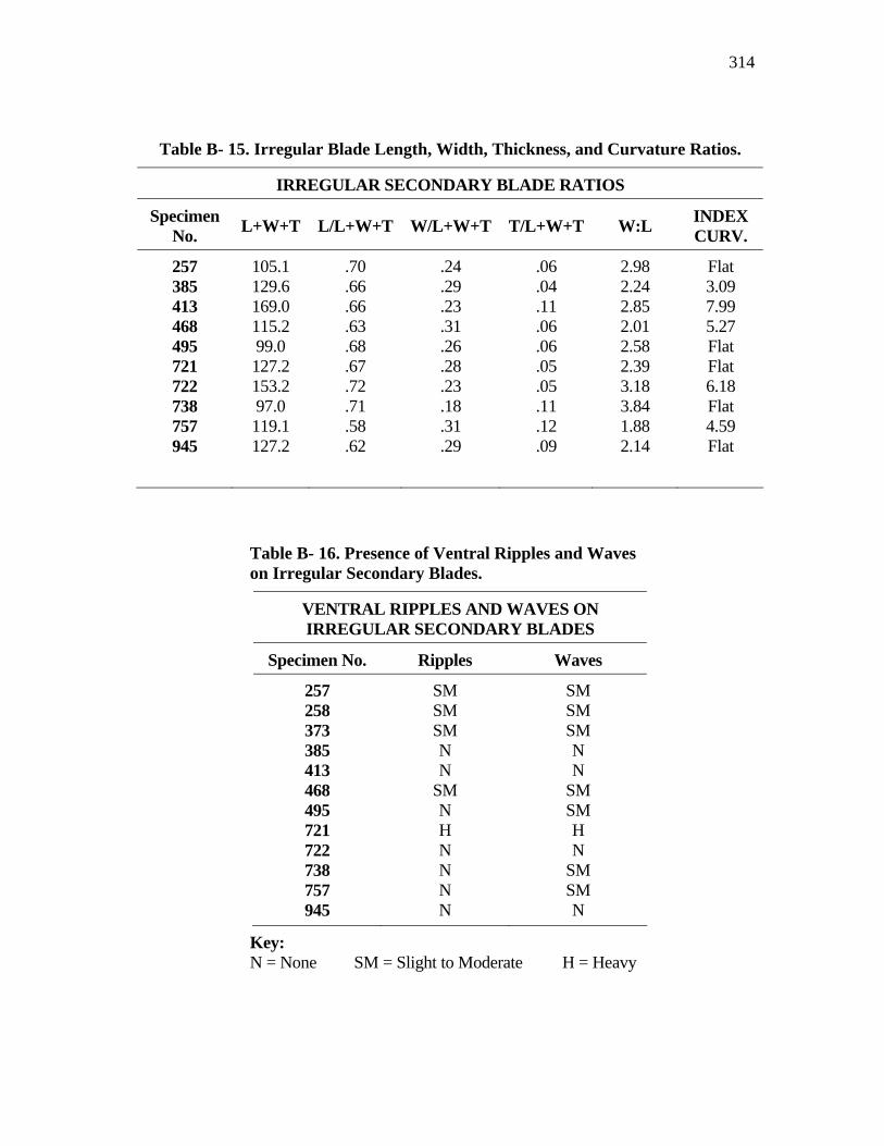
314
Table B- 15. Irregular Blade Length, Width, Thickness, and Curvature Ratios.
IRREGULAR SECONDARY BLADE RATIOS
Specimen No. L+W+T L/L+W+T W/L+W+T T/L+W+T W:L INDEX
CURV.
257 105.1 .70 .24 .06 2.98 Flat 385 129.6 .66 .29 .04 2.24 3.09 413 169.0 .66 .23 .11 2.85 7.99 468 115.2 .63 .31 .06 2.01 5.27 495 99.0 .68 .26 .06 2.58 Flat 721 127.2 .67 .28 .05 2.39 Flat 722 153.2 .72 .23 .05 3.18 6.18 738 97.0 .71 .18 .11 3.84 Flat 757 119.1 .58 .31 .12 1.88 4.59 945 127.2 .62 .29 .09 2.14 Flat
Table B- 16. Presence of Ventral Ripples and Waves on Irregular Secondary Blades.
VENTRAL RIPPLES AND WAVES ON IRREGULAR SECONDARY BLADES
Specimen No. Ripples Waves
257 SM SM 258 SM SM 373 SM SM 385 N N 413 N N 468 SM SM 495 N SM 721 H H 722 N N 738 N SM 757 N SM 945 N N
Key: N = None SM = Slight to Moderate H = Heavy
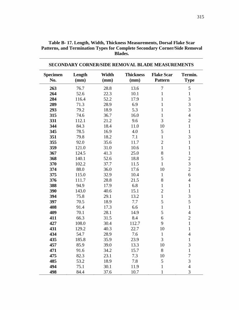
315
Table B- 17. Length, Width, Thickness Measurements, Dorsal Flake Scar Patterns, and Termination Types for Complete Secondary Corner/Side Removal
Blades.
SECONDARY CORNER/SIDE REMOVAL BLADE MEASUREMENTS
Specimen No.
Length (mm)
Width (mm)
Thickness (mm)
Flake Scar Pattern
Termin. Type
263 76.7 28.8 13.6 7 5 264 52.6 22.3 10.1 1 1 284 116.4 52.2 17.9 1 3 289 71.3 28.9 6.9 1 3 293 79.2 18.9 5.3 1 3 315 74.6 36.7 16.0 1 4 331 112.1 21.2 9.6 3 2 344 84.3 18.4 11.0 10 1 345 78.5 16.9 4.0 5 1 351 79.8 18.2 7.1 1 3 355 92.0 35.6 11.7 2 1 359 121.0 31.0 10.6 1 1 367 124.5 41.3 25.0 8 1 368 140.1 52.6 18.8 5 2 370 102.2 37.7 11.5 1 3 374 88.0 36.0 17.6 10 2 375 115.0 32.9 10.4 1 6 376 111.7 28.8 21.5 8 4 388 94.9 17.9 6.8 1 1 390 143.0 40.6 15.1 2 1 394 75.8 29.1 13.2 1 3 397 70.5 18.9 7.7 5 5 408 91.4 17.3 6.6 1 1 409 70.1 28.1 14.9 5 4 411 66.3 31.5 8.4 6 2 427 108.0 30.4 112.7 9 1 431 129.2 40.3 22.7 10 1 434 54.7 28.9 7.6 1 4 435 185.8 35.9 23.9 3 1 457 85.9 39.0 13.3 10 3 471 91.6 34.2 15.7 8 1 475 82.3 23.1 7.3 10 7 485 53.2 18.9 7.8 5 3 494 75.1 30.1 11.9 1 4 498 84.4 37.6 10.7 1 3
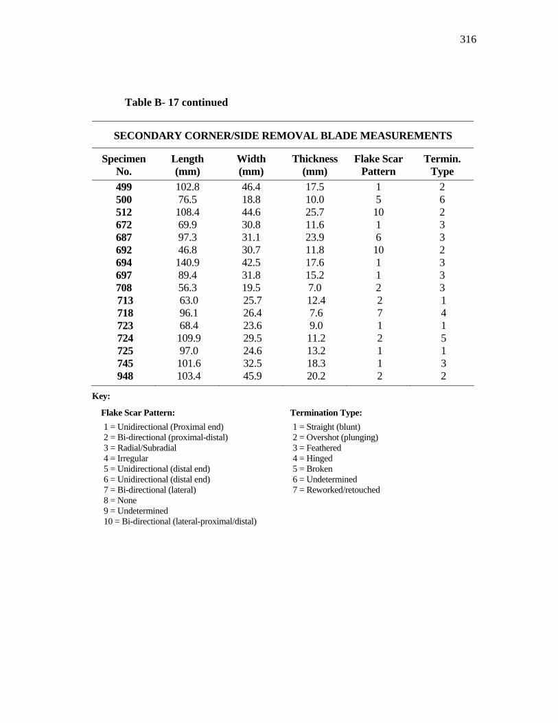
316
Table B- 17 continued
SECONDARY CORNER/SIDE REMOVAL BLADE MEASUREMENTS
Specimen No.
Length (mm)
Width (mm)
Thickness (mm)
Flake Scar Pattern
Termin. Type
499 102.8 46.4 17.5 1 2 500 76.5 18.8 10.0 5 6 512 108.4 44.6 25.7 10 2 672 69.9 30.8 11.6 1 3 687 97.3 31.1 23.9 6 3 692 46.8 30.7 11.8 10 2 694 140.9 42.5 17.6 1 3 697 89.4 31.8 15.2 1 3 708 56.3 19.5 7.0 2 3 713 63.0 25.7 12.4 2 1 718 96.1 26.4 7.6 7 4 723 68.4 23.6 9.0 1 1 724 109.9 29.5 11.2 2 5 725 97.0 24.6 13.2 1 1 745 101.6 32.5 18.3 1 3 948 103.4 45.9 20.2 2 2
Key:
Flake Scar Pattern: Termination Type: 1 = Unidirectional (Proximal end) 2 = Bi-directional (proximal-distal) 3 = Radial/Subradial 4 = Irregular 5 = Unidirectional (distal end) 6 = Unidirectional (distal end) 7 = Bi-directional (lateral) 8 = None 9 = Undetermined 10 = Bi-directional (lateral-proximal/distal)
1 = Straight (blunt) 2 = Overshot (plunging) 3 = Feathered 4 = Hinged 5 = Broken 6 = Undetermined 7 = Reworked/retouched
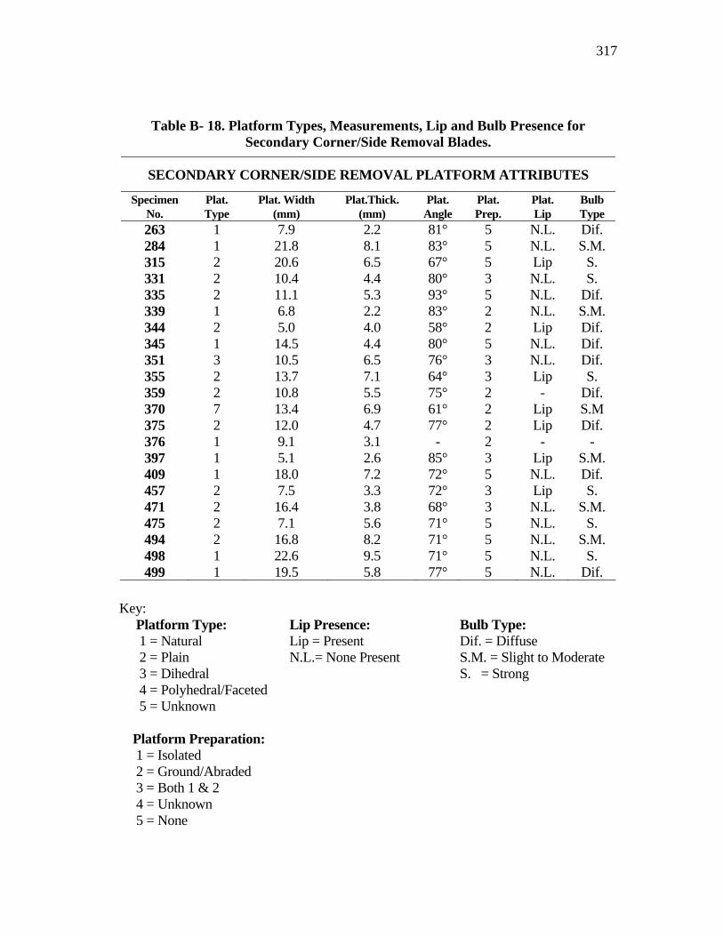
317
Key: Platform Type: Lip Presence: Bulb Type: 1 = Natural Lip = Present Dif. = Diffuse 2 = Plain N.L.= None Present S.M. = Slight to Moderate 3 = Dihedral S. = Strong 4 = Polyhedral/Faceted 5 = Unknown Platform Preparation: 1 = Isolated 2 = Ground/Abraded 3 = Both 1 & 2 4 = Unknown 5 = None
Table B- 18. Platform Types, Measurements, Lip and Bulb Presence for Secondary Corner/Side Removal Blades.
SECONDARY CORNER/SIDE REMOVAL PLATFORM ATTRIBUTES
Specimen No.
Plat. Type
Plat. Width (mm)
Plat.Thick. (mm)
Plat. Angle
Plat. Prep.
Plat. Lip
Bulb Type
263 1 7.9 2.2 81° 5 N.L. Dif. 284 1 21.8 8.1 83° 5 N.L. S.M. 315 2 20.6 6.5 67° 5 Lip S. 331 2 10.4 4.4 80° 3 N.L. S. 335 2 11.1 5.3 93° 5 N.L. Dif. 339 1 6.8 2.2 83° 2 N.L. S.M. 344 2 5.0 4.0 58° 2 Lip Dif. 345 1 14.5 4.4 80° 5 N.L. Dif. 351 3 10.5 6.5 76° 3 N.L. Dif. 355 2 13.7 7.1 64° 3 Lip S. 359 2 10.8 5.5 75° 2 - Dif. 370 7 13.4 6.9 61° 2 Lip S.M 375 2 12.0 4.7 77° 2 Lip Dif. 376 1 9.1 3.1 - 2 - - 397 1 5.1 2.6 85° 3 Lip S.M. 409 1 18.0 7.2 72° 5 N.L. Dif. 457 2 7.5 3.3 72° 3 Lip S. 471 2 16.4 3.8 68° 3 N.L. S.M. 475 2 7.1 5.6 71° 5 N.L. S. 494 2 16.8 8.2 71° 5 N.L. S.M. 498 1 22.6 9.5 71° 5 N.L. S. 499 1 19.5 5.8 77° 5 N.L. Dif.
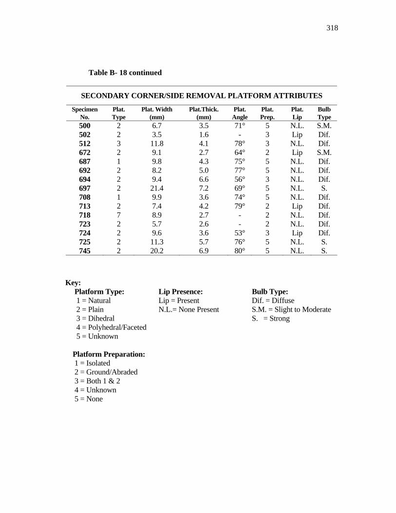
318
Table B- 18 continued
SECONDARY CORNER/SIDE REMOVAL PLATFORM ATTRIBUTES
Specimen No.
Plat. Type
Plat. Width (mm)
Plat.Thick. (mm)
Plat. Angle
Plat. Prep.
Plat. Lip
Bulb Type
500 2 6.7 3.5 71° 5 N.L. S.M. 502 2 3.5 1.6 - 3 Lip Dif. 512 3 11.8 4.1 78° 3 N.L. Dif. 672 2 9.1 2.7 64° 2 Lip S.M. 687 1 9.8 4.3 75° 5 N.L. Dif. 692 2 8.2 5.0 77° 5 N.L. Dif. 694 2 9.4 6.6 56° 3 N.L. Dif. 697 2 21.4 7.2 69° 5 N.L. S. 708 1 9.9 3.6 74° 5 N.L. Dif. 713 2 7.4 4.2 79° 2 Lip Dif. 718 7 8.9 2.7 - 2 N.L. Dif. 723 2 5.7 2.6 - 2 N.L. Dif. 724 2 9.6 3.6 53° 3 Lip Dif. 725 2 11.3 5.7 76° 5 N.L. S. 745 2 20.2 6.9 80° 5 N.L. S.
Key: Platform Type: Lip Presence: Bulb Type: 1 = Natural Lip = Present Dif. = Diffuse 2 = Plain N.L.= None Present S.M. = Slight to Moderate 3 = Dihedral S. = Strong 4 = Polyhedral/Faceted 5 = Unknown Platform Preparation: 1 = Isolated 2 = Ground/Abraded 3 = Both 1 & 2 4 = Unknown 5 = None
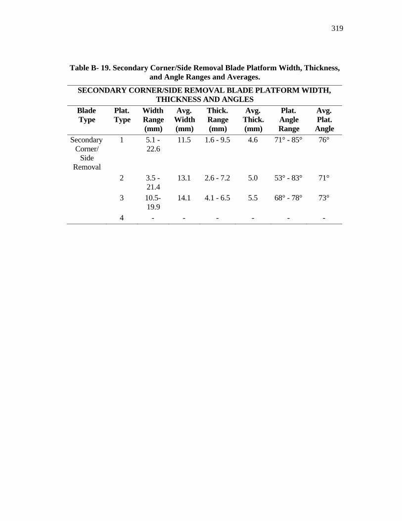
319
Table B- 19. Secondary Corner/Side Removal Blade Platform Width, Thickness, and Angle Ranges and Averages.
SECONDARY CORNER/SIDE REMOVAL BLADE PLATFORM WIDTH, THICKNESS AND ANGLES
Blade Type
Plat. Type
Width Range (mm)
Avg. Width (mm)
Thick. Range (mm)
Avg. Thick. (mm)
Plat. Angle Range
Avg. Plat.
Angle Secondary
Corner/ Side
Removal
1 5.1 - 22.6
11.5 1.6 - 9.5 4.6 71° - 85° 76°
2 3.5 - 21.4
13.1 2.6 - 7.2 5.0 53° - 83° 71°
3 10.5- 19.9
14.1 4.1 - 6.5 5.5 68° - 78° 73°
4 - - - - - -
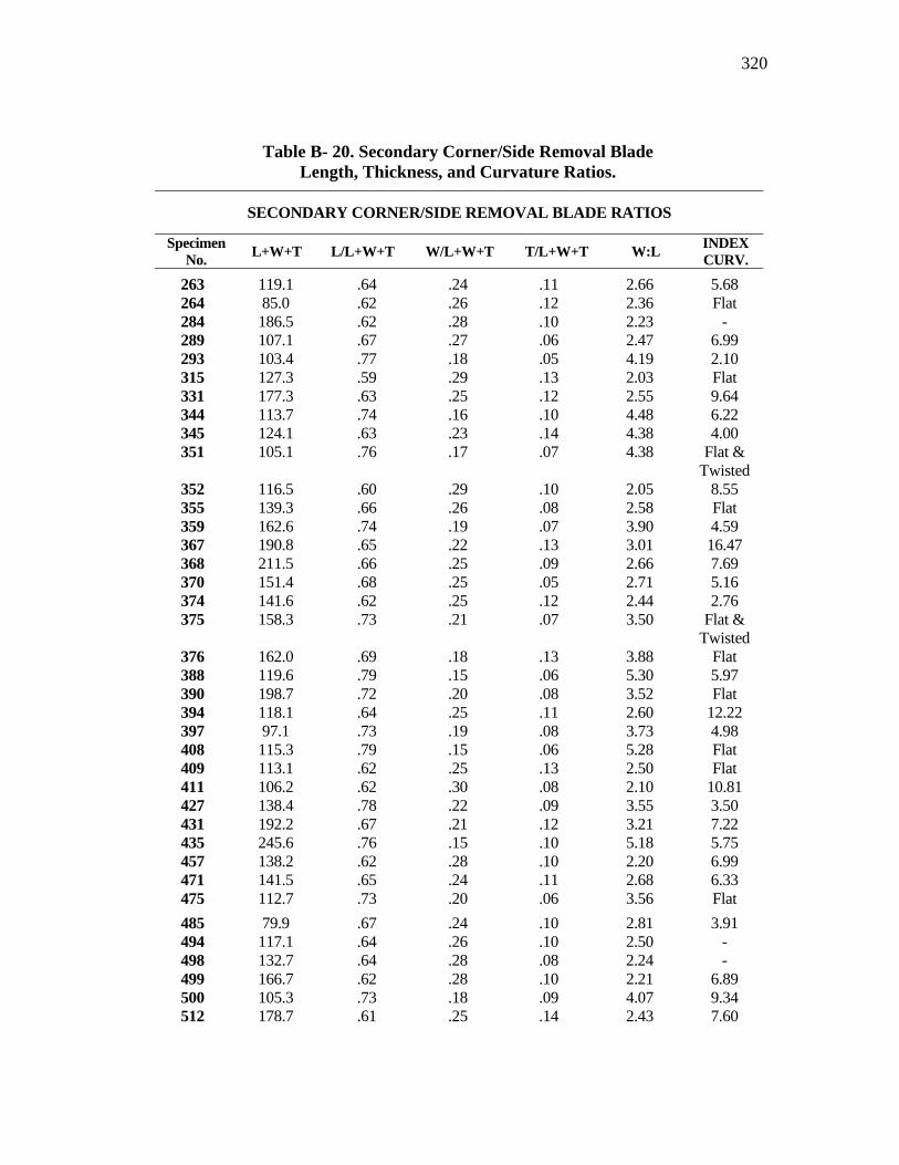
320
Table B- 20. Secondary Corner/Side Removal Blade Length, Thickness, and Curvature Ratios.
SECONDARY CORNER/SIDE REMOVAL BLADE RATIOS
Specimen No. L+W+T L/L+W+T W/L+W+T T/L+W+T W:L INDEX
CURV.
263 119.1 .64 .24 .11 2.66 5.68 264 85.0 .62 .26 .12 2.36 Flat 284 186.5 .62 .28 .10 2.23 - 289 107.1 .67 .27 .06 2.47 6.99 293 103.4 .77 .18 .05 4.19 2.10 315 127.3 .59 .29 .13 2.03 Flat 331 177.3 .63 .25 .12 2.55 9.64 344 113.7 .74 .16 .10 4.48 6.22 345 124.1 .63 .23 .14 4.38 4.00 351 105.1 .76 .17 .07 4.38 Flat &
Twisted 352 116.5 .60 .29 .10 2.05 8.55 355 139.3 .66 .26 .08 2.58 Flat 359 162.6 .74 .19 .07 3.90 4.59 367 190.8 .65 .22 .13 3.01 16.47 368 211.5 .66 .25 .09 2.66 7.69 370 151.4 .68 .25 .05 2.71 5.16 374 141.6 .62 .25 .12 2.44 2.76 375 158.3 .73 .21 .07 3.50 Flat &
Twisted 376 162.0 .69 .18 .13 3.88 Flat 388 119.6 .79 .15 .06 5.30 5.97 390 198.7 .72 .20 .08 3.52 Flat 394 118.1 .64 .25 .11 2.60 12.22 397 97.1 .73 .19 .08 3.73 4.98 408 115.3 .79 .15 .06 5.28 Flat 409 113.1 .62 .25 .13 2.50 Flat 411 106.2 .62 .30 .08 2.10 10.81 427 138.4 .78 .22 .09 3.55 3.50 431 192.2 .67 .21 .12 3.21 7.22 435 245.6 .76 .15 .10 5.18 5.75 457 138.2 .62 .28 .10 2.20 6.99 471 141.5 .65 .24 .11 2.68 6.33 475 112.7 .73 .20 .06 3.56 Flat 485 79.9 .67 .24 .10 2.81 3.91 494 117.1 .64 .26 .10 2.50 - 498 132.7 .64 .28 .08 2.24 - 499 166.7 .62 .28 .10 2.21 6.89 500 105.3 .73 .18 .09 4.07 9.34 512 178.7 .61 .25 .14 2.43 7.60
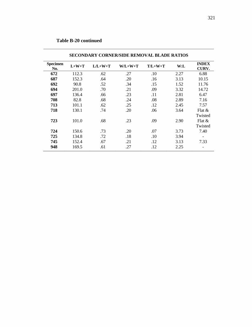
321
Table B-20 continued
SECONDARY CORNER/SIDE REMOVAL BLADE RATIOS
Specimen No. L+W+T L/L+W+T W/L+W+T T/L+W+T W:L INDEX
CURV. 672 112.3 .62 .27 .10 2.27 6.88 687 152.3 .64 .20 .16 3.13 10.15 692 90.8 .52 .34 .15 1.52 11.76 694 201.0 .70 .21 .09 3.32 14.72 697 136.4 .66 .23 .11 2.81 6.47 708 82.8 .68 .24 .08 2.89 7.16 713 101.1 .62 .25 .12 2.45 7.57 718 130.1 .74 .20 .06 3.64 Flat &
Twisted 723 101.0 .68 .23 .09 2.90 Flat &
Twisted 724 150.6 .73 .20 .07 3.73 7.40 725 134.8 .72 .18 .10 3.94 - 745 152.4 .67 .21 .12 3.13 7.33 948 169.5 .61 .27 .12 2.25 -
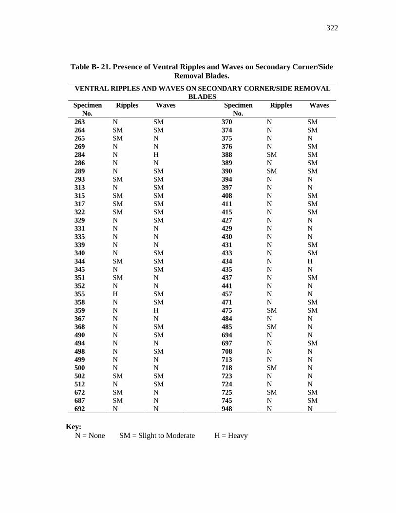
322
Table B- 21. Presence of Ventral Ripples and Waves on Secondary Corner/Side Removal Blades.
VENTRAL RIPPLES AND WAVES ON SECONDARY CORNER/SIDE REMOVAL BLADES
Specimen No.
Ripples Waves Specimen No.
Ripples Waves
263 N SM 370 N SM 264 SM SM 374 N SM 265 SM N 375 N N 269 N N 376 N SM 284 N H 388 SM SM 286 N N 389 N SM 289 N SM 390 SM SM 293 SM SM 394 N N 313 N SM 397 N N 315 SM SM 408 N SM 317 SM SM 411 N SM 322 SM SM 415 N SM 329 N SM 427 N N 331 N N 429 N N 335 N N 430 N N 339 N N 431 N SM 340 N SM 433 N SM 344 SM SM 434 N H 345 N SM 435 N N 351 SM N 437 N SM 352 N N 441 N N 355 H SM 457 N N 358 N SM 471 N SM 359 N H 475 SM SM 367 N N 484 N N 368 N SM 485 SM N 490 N SM 694 N N 494 N N 697 N SM 498 N SM 708 N N 499 N N 713 N N 500 N N 718 SM N 502 SM SM 723 N N 512 N SM 724 N N 672 SM N 725 SM SM 687 SM N 745 N SM 692 N N 948 N N
Key: N = None SM = Slight to Moderate H = Heavy
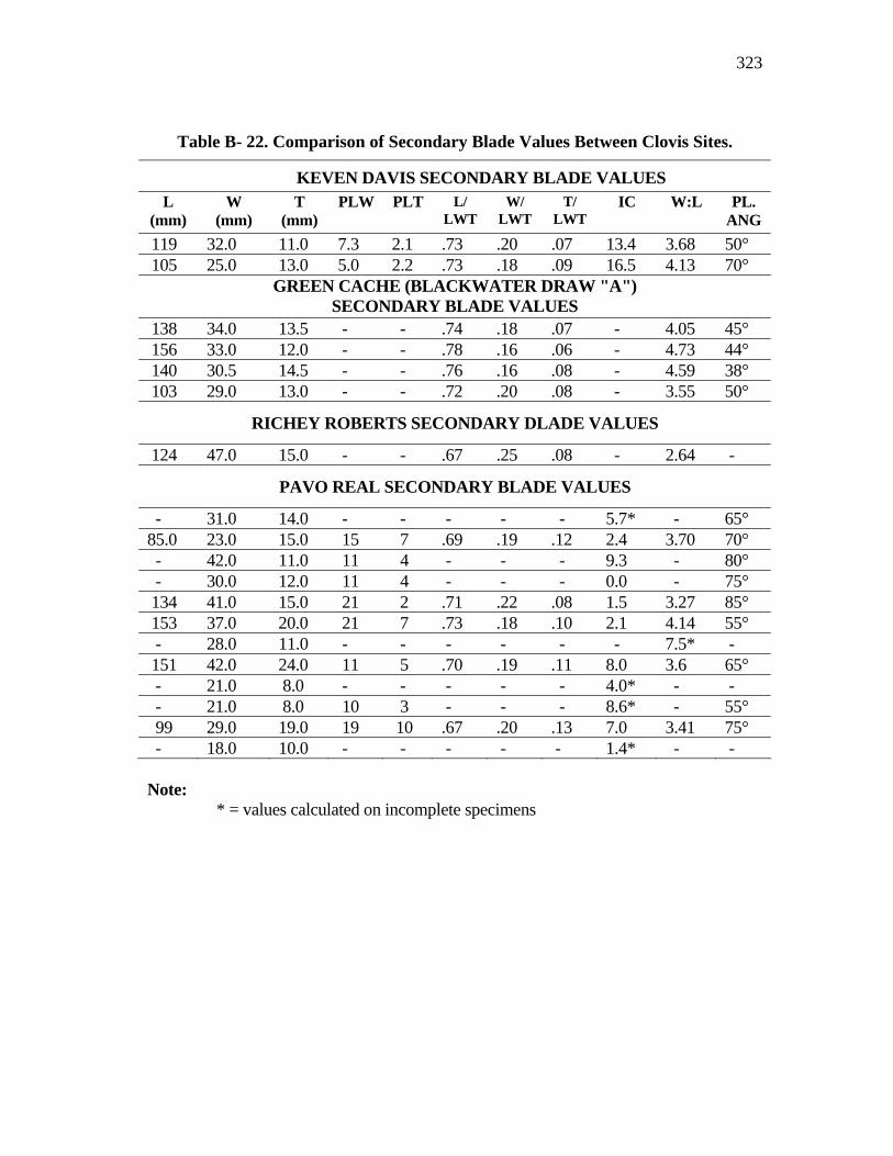
323
Table B- 22. Comparison of Secondary Blade Values Between Clovis Sites.
KEVEN DAVIS SECONDARY BLADE VALUES L
(mm) W
(mm) T
(mm) PLW PLT L/
LWT W/
LWT T/
LWT IC W:L PL.
ANG 119 32.0 11.0 7.3 2.1 .73 .20 .07 13.4 3.68 50° 105 25.0 13.0 5.0 2.2 .73 .18 .09 16.5 4.13 70°
GREEN CACHE (BLACKWATER DRAW "A") SECONDARY BLADE VALUES
138 34.0 13.5 - - .74 .18 .07 - 4.05 45° 156 33.0 12.0 - - .78 .16 .06 - 4.73 44° 140 30.5 14.5 - - .76 .16 .08 - 4.59 38° 103 29.0 13.0 - - .72 .20 .08 - 3.55 50°
RICHEY ROBERTS SECONDARY DLADE VALUES
124 47.0 15.0 - - .67 .25 .08 - 2.64 -
PAVO REAL SECONDARY BLADE VALUES
- 31.0 14.0 - - - - - 5.7* - 65° 85.0 23.0 15.0 15 7 .69 .19 .12 2.4 3.70 70° - 42.0 11.0 11 4 - - - 9.3 - 80° - 30.0 12.0 11 4 - - - 0.0 - 75° 134 41.0 15.0 21 2 .71 .22 .08 1.5 3.27 85° 153 37.0 20.0 21 7 .73 .18 .10 2.1 4.14 55° - 28.0 11.0 - - - - - - 7.5* - 151 42.0 24.0 11 5 .70 .19 .11 8.0 3.6 65° - 21.0 8.0 - - - - - 4.0* - - - 21.0 8.0 10 3 - - - 8.6* - 55° 99 29.0 19.0 19 10 .67 .20 .13 7.0 3.41 75° - 18.0 10.0 - - - - - 1.4* - - Note:
* = values calculated on incomplete specimens
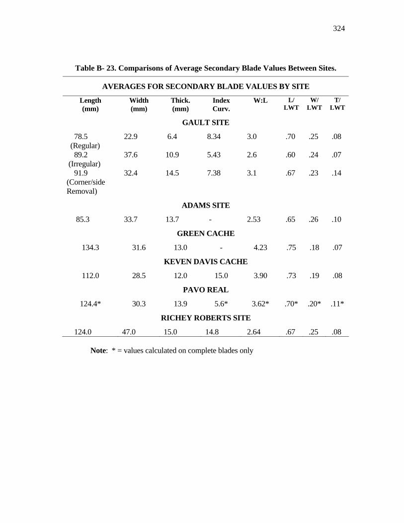
324
Table B- 23. Comparisons of Average Secondary Blade Values Between Sites.
AVERAGES FOR SECONDARY BLADE VALUES BY SITE
Length (mm)
Width (mm)
Thick. (mm)
Index Curv.
W:L L/ LWT
W/ LWT
T/ LWT
GAULT SITE
78.5 (Regular)
22.9 6.4 8.34 3.0 .70 .25 .08
89.2 (Irregular)
37.6 10.9 5.43 2.6 .60 .24 .07
91.9 (Corner/side Removal)
32.4 14.5 7.38 3.1 .67 .23 .14
ADAMS SITE
85.3 33.7 13.7 - 2.53 .65 .26 .10
GREEN CACHE
134.3 31.6 13.0 - 4.23 .75 .18 .07
KEVEN DAVIS CACHE
112.0 28.5 12.0 15.0 3.90 .73 .19 .08
PAVO REAL
124.4* 30.3 13.9 5.6* 3.62* .70* .20* .11*
RICHEY ROBERTS SITE
124.0 47.0 15.0 14.8 2.64 .67 .25 .08 Note: * = values calculated on complete blades only
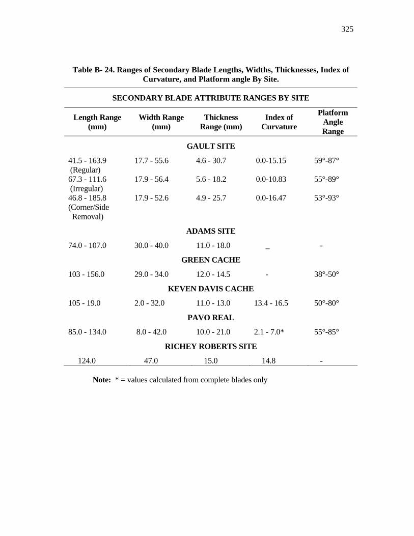
325
Table B- 24. Ranges of Secondary Blade Lengths, Widths, Thicknesses, Index of Curvature, and Platform angle By Site.
SECONDARY BLADE ATTRIBUTE RANGES BY SITE
Length Range (mm)
Width Range (mm)
Thickness Range (mm)
Index of Curvature
Platform Angle Range
GAULT SITE
41.5 - 163.9 (Regular)
17.7 - 55.6 4.6 - 30.7 0.0-15.15
59°-87°
67.3 - 111.6 (Irregular)
17.9 - 56.4 5.6 - 18.2 0.0-10.83 55°-89°
46.8 - 185.8 (Corner/Side Removal)
17.9 - 52.6 4.9 - 25.7 0.0-16.47 53°-93°
ADAMS SITE
74.0 - 107.0 30.0 - 40.0 11.0 - 18.0 _ -
GREEN CACHE
103 - 156.0 29.0 - 34.0 12.0 - 14.5 - 38°-50°
KEVEN DAVIS CACHE
105 - 19.0 2.0 - 32.0 11.0 - 13.0 13.4 - 16.5 50°-80°
PAVO REAL
85.0 - 134.0 8.0 - 42.0 10.0 - 21.0 2.1 - 7.0* 55°-85°
RICHEY ROBERTS SITE
124.0 47.0 15.0 14.8 - Note: * = values calculated from complete blades only
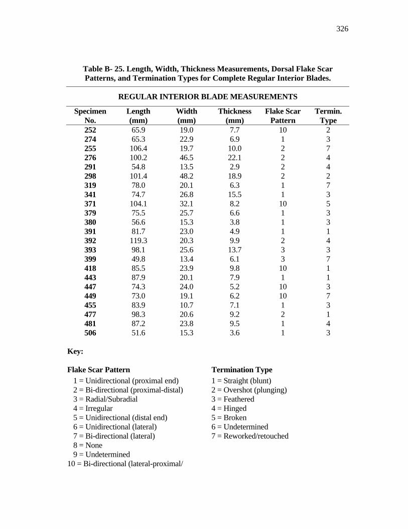
326
Key: Flake Scar Pattern Termination Type
1 = Unidirectional (proximal end) 2 = Bi-directional (proximal-distal) 3 = Radial/Subradial 4 = Irregular 5 = Unidirectional (distal end) 6 = Unidirectional (lateral) 7 = Bi-directional (lateral) 8 = None 9 = Undetermined
10 = Bi-directional (lateral-proximal/
1 = Straight (blunt) 2 = Overshot (plunging) 3 = Feathered 4 = Hinged 5 = Broken 6 = Undetermined 7 = Reworked/retouched
Table B- 25. Length, Width, Thickness Measurements, Dorsal Flake Scar Patterns, and Termination Types for Complete Regular Interior Blades.
REGULAR INTERIOR BLADE MEASUREMENTS
Specimen No.
Length (mm)
Width (mm)
Thickness (mm)
Flake Scar Pattern
Termin. Type
252 65.9 19.0 7.7 10 2 274 65.3 22.9 6.9 1 3 255 106.4 19.7 10.0 2 7 276 100.2 46.5 22.1 2 4 291 54.8 13.5 2.9 2 4 298 101.4 48.2 18.9 2 2 319 78.0 20.1 6.3 1 7 341 74.7 26.8 15.5 1 3 371 104.1 32.1 8.2 10 5 379 75.5 25.7 6.6 1 3 380 56.6 15.3 3.8 1 3 391 81.7 23.0 4.9 1 1 392 119.3 20.3 9.9 2 4 393 98.1 25.6 13.7 3 3 399 49.8 13.4 6.1 3 7 418 85.5 23.9 9.8 10 1 443 87.9 20.1 7.9 1 1 447 74.3 24.0 5.2 10 3 449 73.0 19.1 6.2 10 7 455 83.9 10.7 7.1 1 3 477 98.3 20.6 9.2 2 1 481 87.2 23.8 9.5 1 4 506 51.6 15.3 3.6 1 3
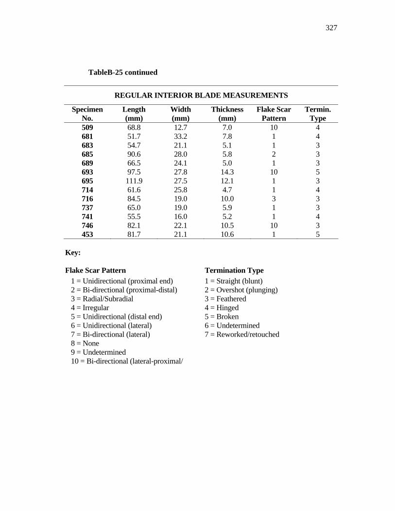
327
TableB-25 continued
REGULAR INTERIOR BLADE MEASUREMENTS
Specimen No.
Length (mm)
Width (mm)
Thickness (mm)
Flake Scar Pattern
Termin. Type
509 68.8 12.7 7.0 10 4 681 51.7 33.2 7.8 1 4 683 54.7 21.1 5.1 1 3 685 90.6 28.0 5.8 2 3 689 66.5 24.1 5.0 1 3 693 97.5 27.8 14.3 10 5 695 111.9 27.5 12.1 1 3 714 61.6 25.8 4.7 1 4 716 84.5 19.0 10.0 3 3 737 65.0 19.0 5.9 1 3 741 55.5 16.0 5.2 1 4 746 82.1 22.1 10.5 10 3 453 81.7 21.1 10.6 1 5
Key: Flake Scar Pattern Termination Type
1 = Unidirectional (proximal end) 2 = Bi-directional (proximal-distal) 3 = Radial/Subradial 4 = Irregular 5 = Unidirectional (distal end) 6 = Unidirectional (lateral) 7 = Bi-directional (lateral) 8 = None 9 = Undetermined 10 = Bi-directional (lateral-proximal/
1 = Straight (blunt) 2 = Overshot (plunging) 3 = Feathered 4 = Hinged 5 = Broken 6 = Undetermined 7 = Reworked/retouched

328
Key: Platform Type: Lip Type:
1 = Natural 2 = Plain 3 = Dihedral 4 = Polyhedral/Faceted 5 = Unknown
Lip = Present N.L. = None Present
Platform Preparation: Bulb Type: 1 = Isolated 2 = Ground/Abraded 3 = Unknown 4 = None 5 = Unknown
Dif. = Diffuse SM = Slight to Moderate S = Strong
Table B- 26. Platform Types, Measurements, Lip and Bulb Presence for Regular Interior Blades.
REGULAR INTERIOR BLADE PLATFORM ATTRIBUTES
Specimen No.
Plat. Type
Plat. Width
Plat. Thick
Plat. Angle
Plat. Prep.
Plat. Lip
Bulb Type
252 4 14.1 4.4 84° 2 Lip Dif. 253 4 8.9 4.9 62° 3 Lip Dif. 276 3 11.4 3.9 51° 3 Lip SM 296 4 6.8 2.5 61° 2 Lip Dif. 298 3 7.2 2.8 65° 3 Lip Dif. 301 4 12.6 4.3 89° 2 - - 371 2 5.6 2.9 52° 3 Lip Dif. 377 3 13.9 5.2 67° 2 Lip SM 382 2 4.7 1.9 56° 3 Lip Dif. 383 2 7.2 1.8 81° 3 Lip Dif. 391 7 5.9 3.0 83° 3 N.L. Dif. 393 2 6.3 3.6 78° 3 N.L. S 399 2 6.2 2.9 73° 3 Lip SM 410 7 6.7 2.4 67° 2 N.L. Dif. 418 3 8.1 3.5 65° 2 Lip Dif. 436 2 6.2 3.6 55° 3 Lip Dif. 447 2 7.2 1.9 64° 2 N.L. SM 449 2 8.0 3.0 75° 3 Lip SM 450 3 10.7 2.3 79° 2 N.L. Dif. 469 4 9.3 3.6 46° 3 N.L. SM 477 2 11.4 4.6 38° 2 - - 487 4 4.2 1.6 - 4 Lip Dif. 501 2 12.1 5.0 50° 3 Lip Dif. 506 2 4.2 2.6 79° 5 N.L. S
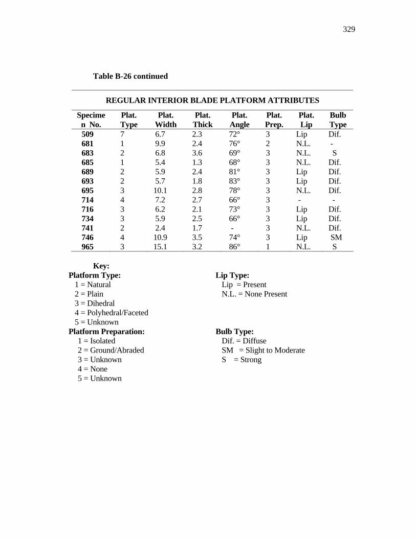
329
Table B-26 continued
REGULAR INTERIOR BLADE PLATFORM ATTRIBUTES
Specimen No.
Plat. Type
Plat. Width
Plat. Thick
Plat. Angle
Plat. Prep.
Plat. Lip
Bulb Type
509 7 6.7 2.3 72° 3 Lip Dif. 681 1 9.9 2.4 76° 2 N.L. - 683 2 6.8 3.6 69° 3 N.L. S 685 1 5.4 1.3 68° 3 N.L. Dif. 689 2 5.9 2.4 81° 3 Lip Dif. 693 2 5.7 1.8 83° 3 Lip Dif. 695 3 10.1 2.8 78° 3 N.L. Dif. 714 4 7.2 2.7 66° 3 - - 716 3 6.2 2.1 73° 3 Lip Dif. 734 3 5.9 2.5 66° 3 Lip Dif. 741 2 2.4 1.7 - 3 N.L. Dif. 746 4 10.9 3.5 74° 3 Lip SM 965 3 15.1 3.2 86° 1 N.L. S
Key:
Platform Type: Lip Type: 1 = Natural 2 = Plain 3 = Dihedral 4 = Polyhedral/Faceted 5 = Unknown
Lip = Present N.L. = None Present
Platform Preparation: Bulb Type: 1 = Isolated 2 = Ground/Abraded 3 = Unknown 4 = None 5 = Unknown
Dif. = Diffuse SM = Slight to Moderate S = Strong
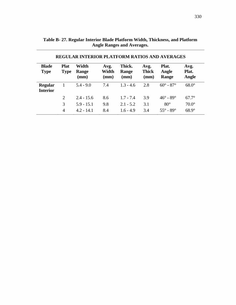
330
Table B- 27. Regular Interior Blade Platform Width, Thickness, and Platform Angle Ranges and Averages.
REGULAR INTERIOR PLATFORM RATIOS AND AVERAGES
Blade Type
Plat Type
Width Range (mm)
Avg. Width (mm)
Thick. Range (mm)
Avg. Thick (mm)
Plat. Angle Range
Avg. Plat. Angle
Regular Interior
1 5.4 - 9.0 7.4 1.3 - 4.6 2.8 60° - 87° 68.0°
2 2.4 - 15.6 8.6 1.7 - 7.4 3.9 46° - 89° 67.7° 3 5.9 - 15.1 9.8 2.1 - 5.2 3.1 80° 70.0° 4 4.2 - 14.1 8.4 1.6 - 4.9 3.4 55° - 89° 68.9°
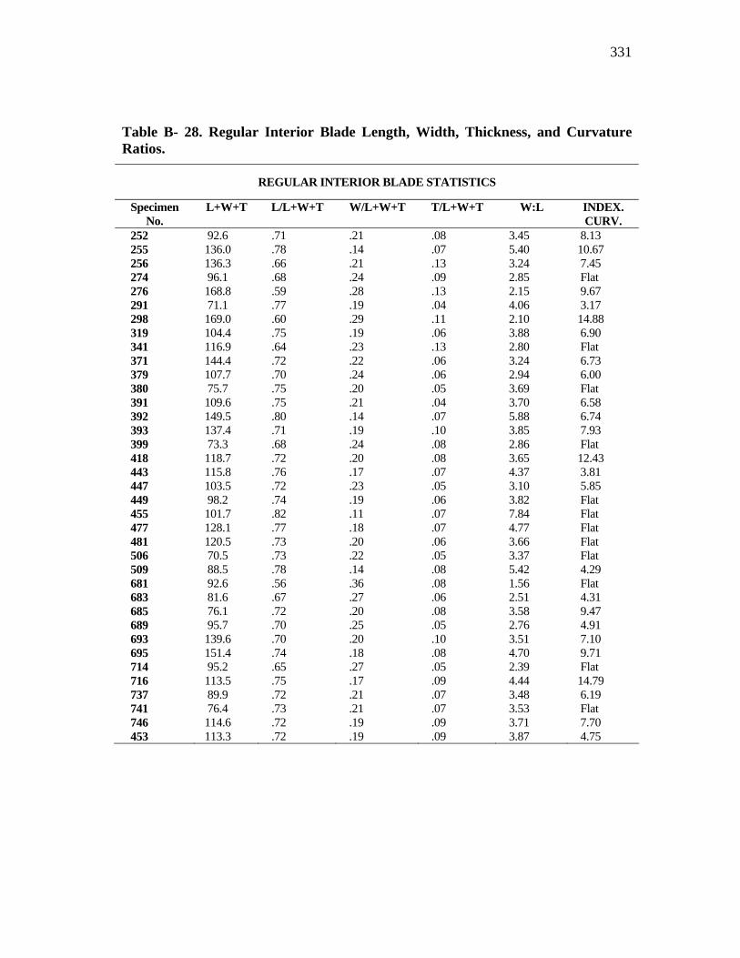
331
Table B- 28. Regular Interior Blade Length, Width, Thickness, and Curvature Ratios.
REGULAR INTERIOR BLADE STATISTICS
Specimen No.
L+W+T L/L+W+T W/L+W+T T/L+W+T W:L INDEX. CURV.
252 92.6 .71 .21 .08 3.45 8.13 255 136.0 .78 .14 .07 5.40 10.67 256 136.3 .66 .21 .13 3.24 7.45 274 96.1 .68 .24 .09 2.85 Flat 276 168.8 .59 .28 .13 2.15 9.67 291 71.1 .77 .19 .04 4.06 3.17 298 169.0 .60 .29 .11 2.10 14.88 319 104.4 .75 .19 .06 3.88 6.90 341 116.9 .64 .23 .13 2.80 Flat 371 144.4 .72 .22 .06 3.24 6.73 379 107.7 .70 .24 .06 2.94 6.00 380 75.7 .75 .20 .05 3.69 Flat 391 109.6 .75 .21 .04 3.70 6.58 392 149.5 .80 .14 .07 5.88 6.74 393 137.4 .71 .19 .10 3.85 7.93 399 73.3 .68 .24 .08 2.86 Flat 418 118.7 .72 .20 .08 3.65 12.43 443 115.8 .76 .17 .07 4.37 3.81 447 103.5 .72 .23 .05 3.10 5.85 449 98.2 .74 .19 .06 3.82 Flat 455 101.7 .82 .11 .07 7.84 Flat 477 128.1 .77 .18 .07 4.77 Flat 481 120.5 .73 .20 .06 3.66 Flat 506 70.5 .73 .22 .05 3.37 Flat 509 88.5 .78 .14 .08 5.42 4.29 681 92.6 .56 .36 .08 1.56 Flat 683 81.6 .67 .27 .06 2.51 4.31 685 76.1 .72 .20 .08 3.58 9.47 689 95.7 .70 .25 .05 2.76 4.91 693 139.6 .70 .20 .10 3.51 7.10 695 151.4 .74 .18 .08 4.70 9.71 714 95.2 .65 .27 .05 2.39 Flat 716 113.5 .75 .17 .09 4.44 14.79 737 89.9 .72 .21 .07 3.48 6.19 741 76.4 .73 .21 .07 3.53 Flat 746 114.6 .72 .19 .09 3.71 7.70 453 113.3 .72 .19 .09 3.87 4.75
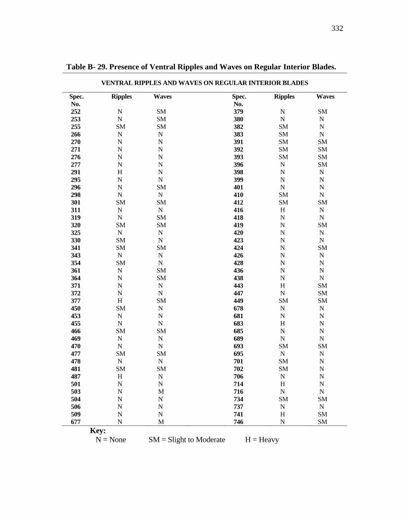
332
Table B- 29. Presence of Ventral Ripples and Waves on Regular Interior Blades.
VENTRAL RIPPLES AND WAVES ON REGULAR INTERIOR BLADES
Spec. No.
Ripples Waves Spec. No.
Ripples Waves
252 N SM 379 N SM 253 N SM 380 N N 255 SM SM 382 SM N 266 N N 383 SM N 270 N N 391 SM SM 271 N N 392 SM SM 276 N N 393 SM SM 277 N N 396 N SM 291 H N 398 N N 295 N N 399 N N 296 N SM 401 N N 298 N N 410 SM N 301 SM SM 412 SM SM 311 N N 416 H N 319 N SM 418 N N 320 SM SM 419 N SM 325 N N 420 N N 330 SM N 423 N N 341 SM SM 424 N SM 343 N N 426 N N 354 SM N 428 N N 361 N SM 436 N N 364 N SM 438 N N 371 N N 443 H SM 372 N N 447 N SM 377 H SM 449 SM SM 450 SM N 678 N N 453 N N 681 N N 455 N N 683 H N 466 SM SM 685 N N 469 N N 689 N N 470 N N 693 SM SM 477 SM SM 695 N N 478 N N 701 SM N 481 SM SM 702 SM N 487 H N 706 N N 501 N N 714 H N 503 N M 716 N N 504 N N 734 SM SM 506 N N 737 N N 509 N N 741 H SM 677 N M 746 N SM
Key: N = None SM = Slight to Moderate H = Heavy
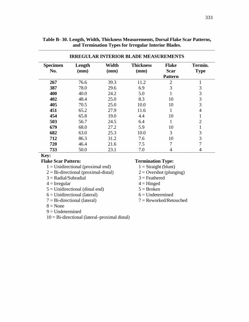
333
Table B- 30. Length, Width, Thickness Measurements, Dorsal Flake Scar Patterns, and Termination Types for Irregular Interior Blades.
IRREGULAR INTERIOR BLADE MEASUREMENTS
Specimen No.
Length (mm)
Width (mm)
Thickness (mm)
Flake Scar
Pattern
Termin. Type
267 76.6 39.3 11.2 2 1 387 78.0 29.6 6.9 3 3 400 40.0 24.2 5.0 1 3 402 48.4 25.0 8.3 10 3 405 70.5 25.0 10.0 10 3 451 65.2 27.9 11.6 1 4 454 65.8 19.0 4.4 10 1 503 56.7 24.5 6.4 1 2 679 68.0 27.2 5.9 10 1 682 63.0 25.3 10.0 3 3 712 86.3 31.2 7.6 10 3 720 46.4 21.6 7.5 7 7 733 50.0 23.1 7.0 4 4
Key: Flake Scar Pattern: Termination Type:
1 = Unidirectional (proximal end) 2 = Bi-directional (proximal-distal) 3 = Radial/Subradial 4 = Irregular 5 = Unidirectional (distal end) 6 = Unidirectional (lateral) 7 = Bi-directional (lateral) 8 = None 9 = Undetermined 10 = Bi-directional (lateral–proximal distal)
1 = Straight (blunt) 2 = Overshot (plunging) 3 = Feathered 4 = Hinged 5 = Broken 6 = Undetermined 7 = Reworked/Retouched
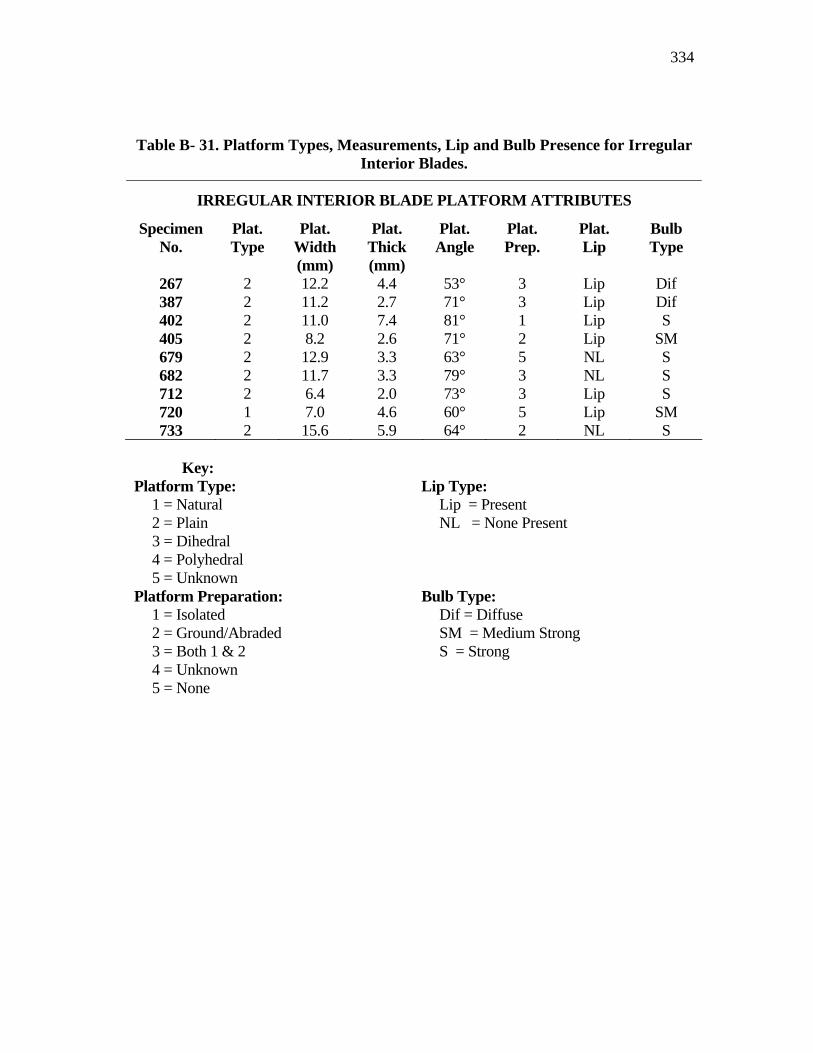
334
Table B- 31. Platform Types, Measurements, Lip and Bulb Presence for Irregular Interior Blades.
IRREGULAR INTERIOR BLADE PLATFORM ATTRIBUTES
Specimen No.
Plat. Type
Plat. Width (mm)
Plat. Thick (mm)
Plat. Angle
Plat. Prep.
Plat. Lip
Bulb Type
267 2 12.2 4.4 53° 3 Lip Dif 387 2 11.2 2.7 71° 3 Lip Dif 402 2 11.0 7.4 81° 1 Lip S 405 2 8.2 2.6 71° 2 Lip SM 679 2 12.9 3.3 63° 5 NL S 682 2 11.7 3.3 79° 3 NL S 712 2 6.4 2.0 73° 3 Lip S 720 1 7.0 4.6 60° 5 Lip SM 733 2 15.6 5.9 64° 2 NL S
Key:
Platform Type: Lip Type: 1 = Natural 2 = Plain 3 = Dihedral 4 = Polyhedral 5 = Unknown
Lip = Present NL = None Present
Platform Preparation: Bulb Type: 1 = Isolated 2 = Ground/Abraded 3 = Both 1 & 2 4 = Unknown 5 = None
Dif = Diffuse SM = Medium Strong S = Strong
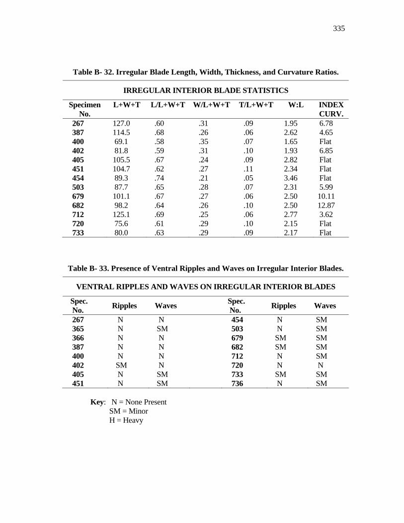
335
Table B- 32. Irregular Blade Length, Width, Thickness, and Curvature Ratios.
IRREGULAR INTERIOR BLADE STATISTICS
Specimen No.
L+W+T L/L+W+T W/L+W+T T/L+W+T W:L INDEX CURV.
267 127.0 .60 .31 .09 1.95 6.78 387 114.5 .68 .26 .06 2.62 4.65 400 69.1 .58 .35 .07 1.65 Flat 402 81.8 .59 .31 .10 1.93 6.85 405 105.5 .67 .24 .09 2.82 Flat 451 104.7 .62 .27 .11 2.34 Flat 454 89.3 .74 .21 .05 3.46 Flat 503 87.7 .65 .28 .07 2.31 5.99 679 101.1 .67 .27 .06 2.50 10.11 682 98.2 .64 .26 .10 2.50 12.87 712 125.1 .69 .25 .06 2.77 3.62 720 75.6 .61 .29 .10 2.15 Flat 733 80.0 .63 .29 .09 2.17 Flat
Table B- 33. Presence of Ventral Ripples and Waves on Irregular Interior Blades.
VENTRAL RIPPLES AND WAVES ON IRREGULAR INTERIOR BLADES
Spec. No. Ripples Waves Spec.
No. Ripples Waves
267 N N 454 N SM 365 N SM 503 N SM 366 N N 679 SM SM 387 N N 682 SM SM 400 N N 712 N SM 402 SM N 720 N N 405 N SM 733 SM SM 451 N SM 736 N SM
Key: N = None Present SM = Minor H = Heavy
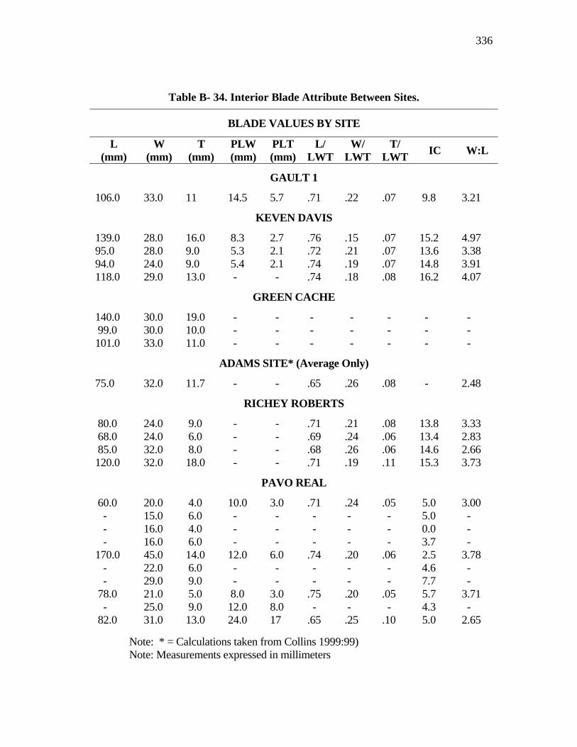
336
Note: * = Calculations taken from Collins 1999:99) Note: Measurements expressed in millimeters
Table B- 34. Interior Blade Attribute Between Sites.
BLADE VALUES BY SITE
L (mm)
W (mm)
T (mm)
PLW (mm)
PLT (mm)
L/ LWT
W/ LWT
T/ LWT IC W:L
GAULT 1
106.0 33.0 11 14.5 5.7 .71 .22 .07 9.8 3.21
KEVEN DAVIS
139.0 28.0 16.0 8.3 2.7 .76 .15 .07 15.2 4.97 95.0 28.0 9.0 5.3 2.1 .72 .21 .07 13.6 3.38 94.0 24.0 9.0 5.4 2.1 .74 .19 .07 14.8 3.91 118.0 29.0 13.0 - - .74 .18 .08 16.2 4.07
GREEN CACHE
140.0 30.0 19.0 - - - - - - - 99.0 30.0 10.0 - - - - - - - 101.0 33.0 11.0 - - - - - - -
ADAMS SITE* (Average Only)
75.0 32.0 11.7 - - .65 .26 .08 - 2.48
RICHEY ROBERTS
80.0 24.0 9.0 - - .71 .21 .08 13.8 3.33 68.0 24.0 6.0 - - .69 .24 .06 13.4 2.83 85.0 32.0 8.0 - - .68 .26 .06 14.6 2.66 120.0 32.0 18.0 - - .71 .19 .11 15.3 3.73
PAVO REAL
60.0 20.0 4.0 10.0 3.0 .71 .24 .05 5.0 3.00 - 15.0 6.0 - - - - - 5.0 - - 16.0 4.0 - - - - - 0.0 - - 16.0 6.0 - - - - - 3.7 - 170.0 45.0 14.0 12.0 6.0 .74 .20 .06 2.5 3.78 - 22.0 6.0 - - - - - 4.6 - - 29.0 9.0 - - - - - 7.7 - 78.0 21.0 5.0 8.0 3.0 .75 .20 .05 5.7 3.71 - 25.0 9.0 12.0 8.0 - - - 4.3 - 82.0 31.0 13.0 24.0 17 .65 .25 .10 5.0 2.65
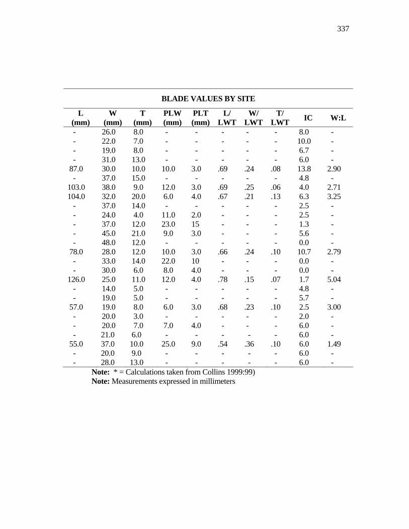
337
BLADE VALUES BY SITE
L (mm)
W (mm)
T (mm)
PLW (mm)
PLT (mm)
L/ LWT
W/ LWT
T/ LWT IC W:L
- 26.0 8.0 - - - - - 8.0 - - 22.0 7.0 - - - - - 10.0 - - 19.0 8.0 - - - - - 6.7 - - 31.0 13.0 - - - - - 6.0 - 87.0 30.0 10.0 10.0 3.0 .69 .24 .08 13.8 2.90 - 37.0 15.0 - - - - - 4.8 - 103.0 38.0 9.0 12.0 3.0 .69 .25 .06 4.0 2.71 104.0 32.0 20.0 6.0 4.0 .67 .21 .13 6.3 3.25 - 37.0 14.0 - - - - - 2.5 - - 24.0 4.0 11.0 2.0 - - - 2.5 - - 37.0 12.0 23.0 15 - - - 1.3 - - 45.0 21.0 9.0 3.0 - - - 5.6 - - 48.0 12.0 - - - - - 0.0 - 78.0 28.0 12.0 10.0 3.0 .66 .24 .10 10.7 2.79 - 33.0 14.0 22.0 10 - - - 0.0 - - 30.0 6.0 8.0 4.0 - - - 0.0 - 126.0 25.0 11.0 12.0 4.0 .78 .15 .07 1.7 5.04 - 14.0 5.0 - - - - - 4.8 - - 19.0 5.0 - - - - - 5.7 - 57.0 19.0 8.0 6.0 3.0 .68 .23 .10 2.5 3.00 - 20.0 3.0 - - - - - 2.0 - - 20.0 7.0 7.0 4.0 - - - 6.0 - - 21.0 6.0 - - - - - 6.0 - 55.0 37.0 10.0 25.0 9.0 .54 .36 .10 6.0 1.49 - 20.0 9.0 - - - - - 6.0 - - 28.0 13.0 - - - - - 6.0 -
Note: * = Calculations taken from Collins 1999:99) Note: Measurements expressed in millimeters
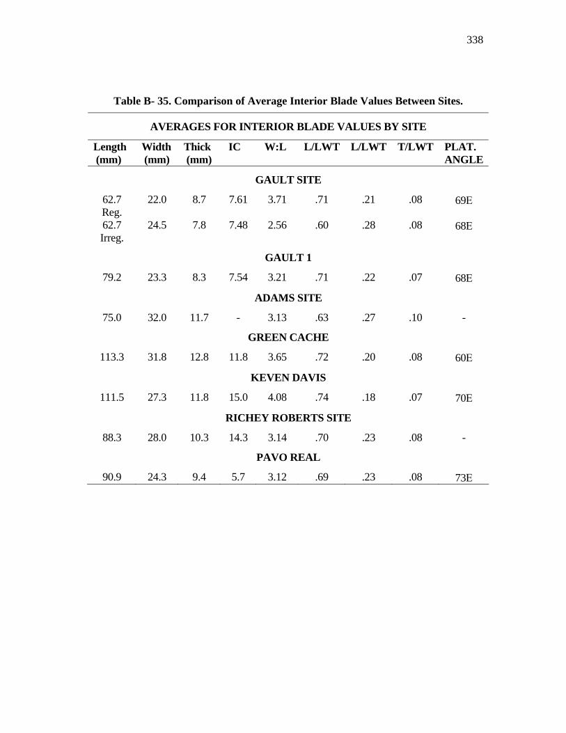
338
Table B- 35. Comparison of Average Interior Blade Values Between Sites.
AVERAGES FOR INTERIOR BLADE VALUES BY SITE
Length (mm)
Width (mm)
Thick (mm)
IC W:L L/LWT L/LWT T/LWT PLAT. ANGLE
GAULT SITE
62.7 Reg.
22.0 8.7 7.61 3.71 .71 .21 .08 69Ε
62.7 Irreg.
24.5 7.8 7.48 2.56 .60 .28 .08 68Ε
GAULT 1
79.2 23.3 8.3 7.54 3.21 .71 .22 .07 68Ε
ADAMS SITE
75.0 32.0 11.7 - 3.13 .63 .27 .10 -
GREEN CACHE
113.3 31.8 12.8 11.8 3.65 .72 .20 .08 60Ε
KEVEN DAVIS
111.5 27.3 11.8 15.0 4.08 .74 .18 .07 70Ε
RICHEY ROBERTS SITE
88.3 28.0 10.3 14.3 3.14 .70 .23 .08 -
PAVO REAL
90.9 24.3 9.4 5.7 3.12 .69 .23 .08 73Ε
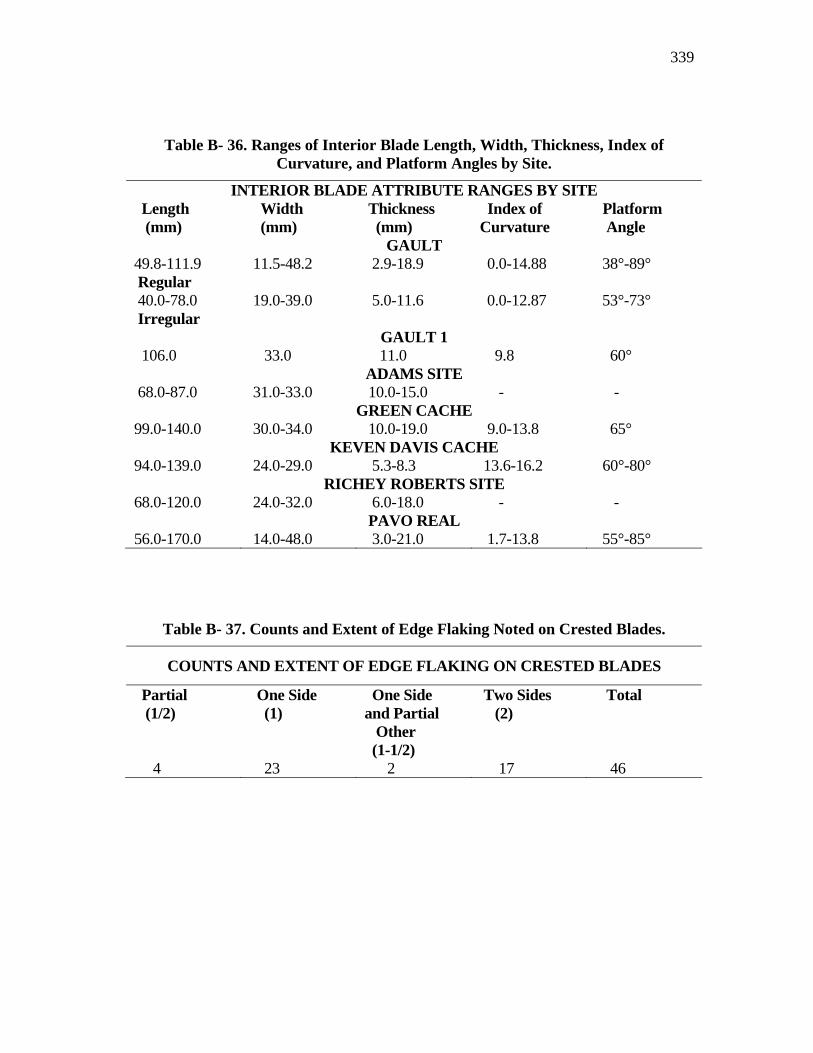
339
Table B- 36. Ranges of Interior Blade Length, Width, Thickness, Index of Curvature, and Platform Angles by Site.
INTERIOR BLADE ATTRIBUTE RANGES BY SITE Length (mm)
Width (mm)
Thickness (mm)
Index of Curvature
Platform Angle
GAULT 49.8-111.9 Regular
11.5-48.2 2.9-18.9 0.0-14.88 38°-89°
40.0-78.0 Irregular
19.0-39.0 5.0-11.6 0.0-12.87 53°-73°
GAULT 1 106.0 33.0 11.0 9.8 60°
ADAMS SITE 68.0-87.0 31.0-33.0 10.0-15.0 - -
GREEN CACHE 99.0-140.0 30.0-34.0 10.0-19.0 9.0-13.8 65°
KEVEN DAVIS CACHE 94.0-139.0 24.0-29.0 5.3-8.3 13.6-16.2 60°-80°
RICHEY ROBERTS SITE 68.0-120.0 24.0-32.0 6.0-18.0 - -
PAVO REAL 56.0-170.0 14.0-48.0 3.0-21.0 1.7-13.8 55°-85°
Table B- 37. Counts and Extent of Edge Flaking Noted on Crested Blades.
COUNTS AND EXTENT OF EDGE FLAKING ON CRESTED BLADES
Partial (1/2)
One Side (1)
One Side and Partial Other (1-1/2)
Two Sides (2)
Total
4 23 2 17 46
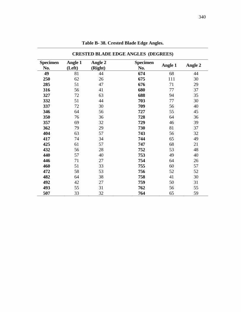
340
Table B- 38. Crested Blade Edge Angles.
CRESTED BLADE EDGE ANGLES (DEGREES)
Specimen No.
Angle 1 (Left)
Angle 2 (Right) Specimen
No. Angle 1 Angle 2
49 81 44 674 68 44 250 62 26 675 111 30 285 51 47 676 71 29 316 56 41 680 77 37 327 72 63 688 94 35 332 51 44 703 77 30 337 72 30 709 56 40 346 64 56 727 55 45 350 76 36 728 64 36 357 69 32 729 46 39 362 79 29 730 81 37 404 63 57 743 56 32 417 74 34 744 65 49 425 61 57 747 68 21 432 56 28 752 53 48 440 57 40 753 49 40 446 71 27 754 64 26 460 51 33 755 60 57 472 58 53 756 52 52 482 64 38 758 41 30 492 42 27 759 50 31 493 55 31 762 56 55 507 33 32 764 65 59
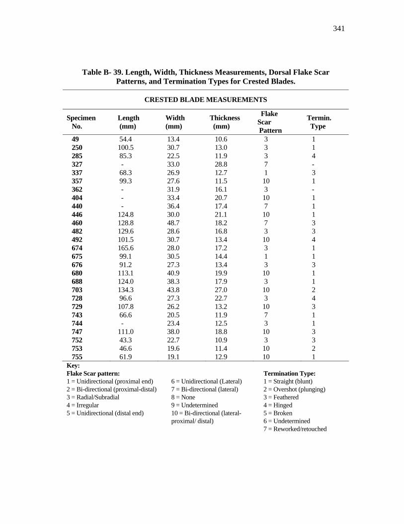
341
Table B- 39. Length, Width, Thickness Measurements, Dorsal Flake Scar Patterns, and Termination Types for Crested Blades.
CRESTED BLADE MEASUREMENTS
Specimen No.
Length (mm)
Width (mm)
Thickness (mm)
Flake Scar Pattern
Termin. Type
49 54.4 13.4 10.6 3 1 250 100.5 30.7 13.0 3 1 285 85.3 22.5 11.9 3 4 327 - 33.0 28.8 7 - 337 68.3 26.9 12.7 1 3 357 99.3 27.6 11.5 10 1 362 - 31.9 16.1 3 - 404 - 33.4 20.7 10 1 440 - 36.4 17.4 7 1 446 124.8 30.0 21.1 10 1 460 128.8 48.7 18.2 7 3 482 129.6 28.6 16.8 3 3 492 101.5 30.7 13.4 10 4 674 165.6 28.0 17.2 3 1 675 99.1 30.5 14.4 1 1 676 91.2 27.3 13.4 3 3 680 113.1 40.9 19.9 10 1 688 124.0 38.3 17.9 3 1 703 134.3 43.8 27.0 10 2 728 96.6 27.3 22.7 3 4 729 107.8 26.2 13.2 10 3 743 66.6 20.5 11.9 7 1 744 - 23.4 12.5 3 1 747 111.0 38.0 18.8 10 3 752 43.3 22.7 10.9 3 3 753 46.6 19.6 11.4 10 2 755 61.9 19.1 12.9 10 1 Key: Flake Scar pattern: Termination Type: 1 = Unidirectional (proximal end) 2 = Bi-directional (proximal-distal) 3 = Radial/Subradial 4 = Irregular 5 = Unidirectional (distal end)
6 = Unidirectional (Lateral) 7 = Bi-directional (lateral) 8 = None 9 = Undetermined 10 = Bi-directional (lateral-proximal/ distal)
1 = Straight (blunt) 2 = Overshot (plunging) 3 = Feathered 4 = Hinged 5 = Broken 6 = Undetermined 7 = Reworked/retouched
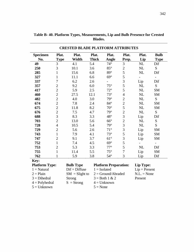
342
Table B- 40. Platform Types, Measurements, Lip and Bulb Presence for Crested Blades.
CRESTED BLADE PLATFORM ATTRIBUTES
Specimen No.
Plat. Type
Plat. Width
Plat. Thick
Plat. Angle
Plat. Prep.
Plat. Lip
Bulb Type
49 3 4.1 5.4 74° 3 NL Dif 250 3 10.1 3.6 85° 2 NL S 285 1 15.6 6.8 89° 5 NL Dif 327 1 11.1 6.6 69° 5 - - 337 7 6.2 2.6 - 3 Lip Dif 357 2 9.2 6.0 75° 5 NL S 417 2 5.9 2.5 72° 5 NL SM 460 2 27.5 12.1 73° 4 NL SM 482 2 4.0 3.0 79° 2 NL S 674 2 7.8 2.4 84° 2 NL SM 675 2 11.8 8.2 70° 5 NL SM 676 2 7.5 4.7 79° 2 NL S 688 3 8.3 3.3 48° 3 Lip Dif 703 2 13.0 5.6 66° 2 NL S 728 4 10.5 5.4 79° 3 NL S 729 2 5.6 2.6 71° 3 Lip SM 743 1 7.9 4.1 73° 5 Lip SM 747 2 9.1 3.7 61° 3 Lip SM 752 1 7.4 4.5 69° 5 - - 753 2 5.3 3.3 77° 5 NL Dif 755 1 11.4 5.5 75° 7 Lip SM 762 1 5.9 3.8 54° 3 Lip Dif Key: Platform Type: Bulb Type Platform Preparation: Lip Type: 1 = Natural 2 = Plain 3 = Dihedral 4 = Polyhedral 5 = Unknown
Dif = Diffuse SM = Slight to Strong S = Strong
1 = Isolated 2 = Ground/Abraded 3 = Both 1 & 2 4 = Unknown 5 = None
Lip = Present N.L. = None Present
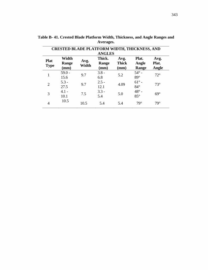
343
Table B- 41. Crested Blade Platform Width, Thickness, and Angle Ranges and Averages.
CRESTED BLADE PLATFORM WIDTH, THICKNESS, AND ANGLES
Plat Type
Width Range (mm)
Avg. Width
Thick. Range (mm)
Avg. Thick (mm)
Plat. Angle Range
Avg. Plat. Angle
1 59.0 - 15.6 9.7 3.8 -
6.8 5.2 54° - 89° 72°
2 5.3 - 27.5 9.7 2.5 -
12.1 4.09 61° - 84° 73°
3 4.1 - 10.1 7.5 3.3 -
5.4 5.0 48° - 85° 69°
4 10.5 10.5 5.4 5.4 79° 79°
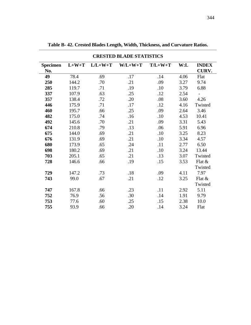
344
Table B- 42. Crested Blades Length, Width, Thickness, and Curvature Ratios.
CRESTED BLADE STATISTICS
Specimen No.
L+W+T L/L+W+T W/L+W+T T/L+W+T W:L INDEX CURV.
49 78.4 .69 .17 .14 4.06 Flat 250 144.2 .70 .21 .09 3.27 9.74 285 119.7 .71 .19 .10 3.79 6.88 337 107.9 .63 .25 .12 2.54 - 357 138.4 .72 .20 .08 3.60 4.26 446 175.9 .71 .17 .12 4.16 Twisted 460 195.7 .66 .25 .09 2.64 3.46 482 175.0 .74 .16 .10 4.53 10.41 492 145.6 .70 .21 .09 3.31 5.43 674 210.8 .79 .13 .06 5.91 6.96 675 144.0 .69 .21 .10 3.25 8.23 676 131.9 .69 .21 .10 3.34 4.57 680 173.9 .65 .24 .11 2.77 6.50 698 180.2 .69 .21 .10 3.24 13.44 703 205.1 .65 .21 .13 3.07 Twisted 728 146.6 .66 .19 .15 3.53 Flat &
Twisted 729 147.2 .73 .18 .09 4.11 7.97 743 99.0 .67 .21 .12 3.25 Flat &
Twisted 747 167.8 .66 .23 .11 2.92 5.11 752 76.9 .56 .30 .14 1.91 9.79 753 77.6 .60 .25 .15 2.38 10.0 755 93.9 .66 .20 .14 3.24 Flat
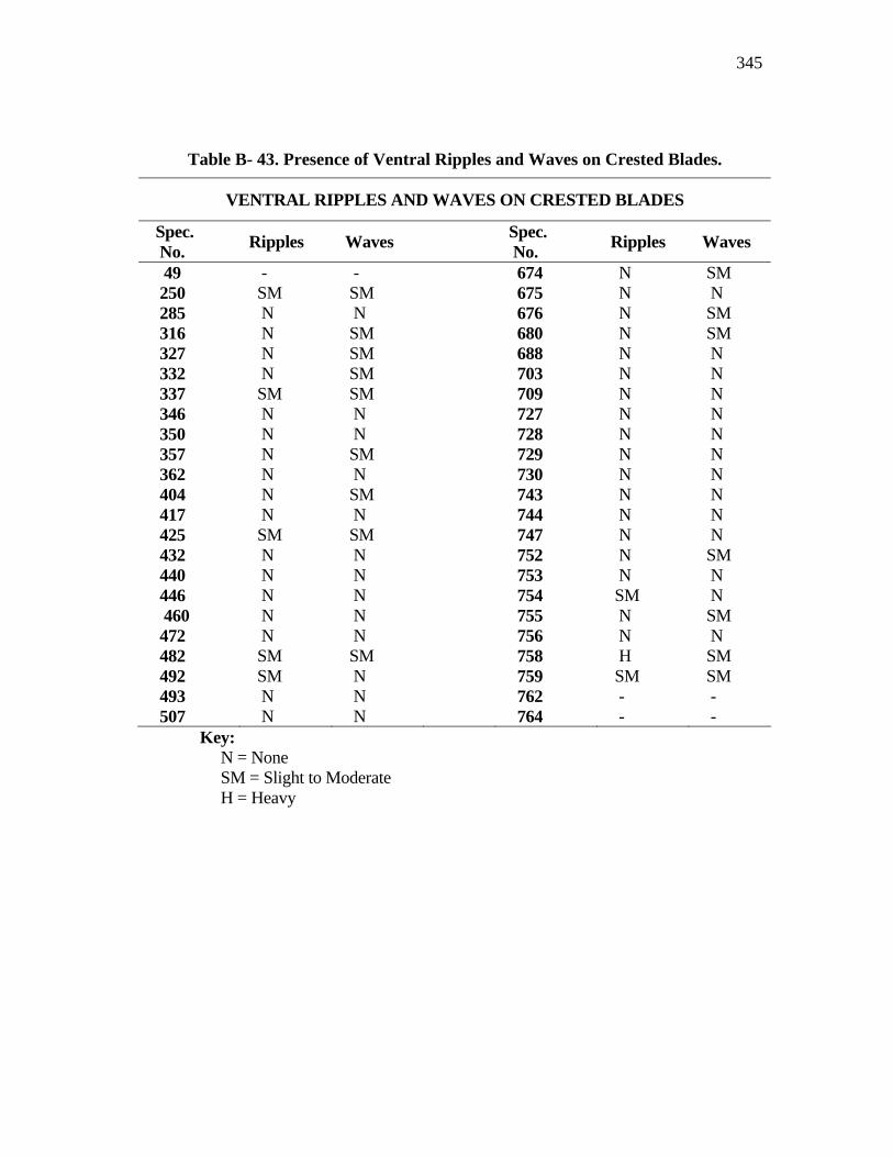
345
Table B- 43. Presence of Ventral Ripples and Waves on Crested Blades.
VENTRAL RIPPLES AND WAVES ON CRESTED BLADES
Spec. No. Ripples Waves Spec.
No. Ripples Waves
49 - - 674 N SM 250 SM SM 675 N N 285 N N 676 N SM 316 N SM 680 N SM 327 N SM 688 N N 332 N SM 703 N N 337 SM SM 709 N N 346 N N 727 N N 350 N N 728 N N 357 N SM 729 N N 362 N N 730 N N 404 N SM 743 N N 417 N N 744 N N 425 SM SM 747 N N 432 N N 752 N SM 440 N N 753 N N 446 N N 754 SM N 460 N N 755 N SM 472 N N 756 N N 482 SM SM 758 H SM 492 SM N 759 SM SM 493 N N 762 - - 507 N N 764 - -
Key: N = None SM = Slight to Moderate H = Heavy
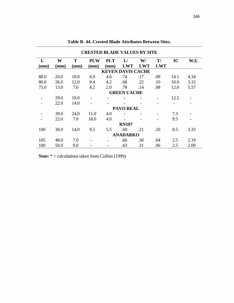
346
Table B- 44. Crested Blade Attributes Between Sites.
CRESTED BLADE VALUES BY SITE
L (mm)
W (mm)
T (mm)
PLW (mm)
PLT (mm)
L/ LWT
W/ LWT
T/ LWT
IC W;L
KEVEN DAVIS CACHE 88.0 20.0 10.0 6.9 4.6 .74 .17 .09 14.1 4.34 80.0 26.0 12.0 9.4 4.2 .68 .22 .10 10.0 3.15 75.0 13.0 7.0 4.2 2.0 .78 .14 .08 12.0 5.57 GREEN CACHE - 29.0 19.0 - - - - - 12.5 - - 22.0 14.0 - - - - - - - PAVO REAL - 39.0 24.0 11.0 4.0 - - - 7.3 - - 22.0 7.0 18.0 4.0 - - - 9.5 - RN107 100 30.0 14.0 9.5 5.5 .69 .21 .10 8.5 3.33 ANADARKO 105 48.0 7.0 - - .66 .30 .04 2.5 2.19 100 50.0 9.0 - - .63 .31 .06 2.5 2.00 Note: * = calculations taken from Collins (1999)
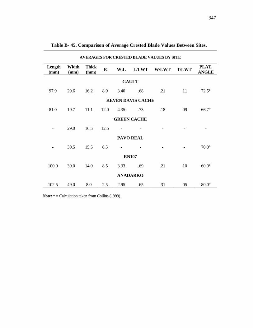
347
Table B- 45. Comparison of Average Crested Blade Values Between Sites.
AVERAGES FOR CRESTED BLADE VALUES BY SITE
Length (mm)
Width (mm)
Thick (mm) IC W:L L/LWT W/LWT T/LWT PLAT.
ANGLE
GAULT
97.9 29.6 16.2 8.0 3.40 .68 .21 .11 72.5°
KEVEN DAVIS CACHE
81.0 19.7 11.1 12.0 4.35 .73 .18 .09 66.7°
GREEN CACHE
- 29.0 16.5 12.5 - - - - -
PAVO REAL
- 30.5 15.5 8.5 - - - - 70.0°
RN107
100.0 30.0 14.0 8.5 3.33 .69 .21 .10 60.0°
ANADARKO
102.5 49.0 8.0 2.5 2.95 .65 .31 .05 80.0° Note: * = Calculation taken from Collins (1999)
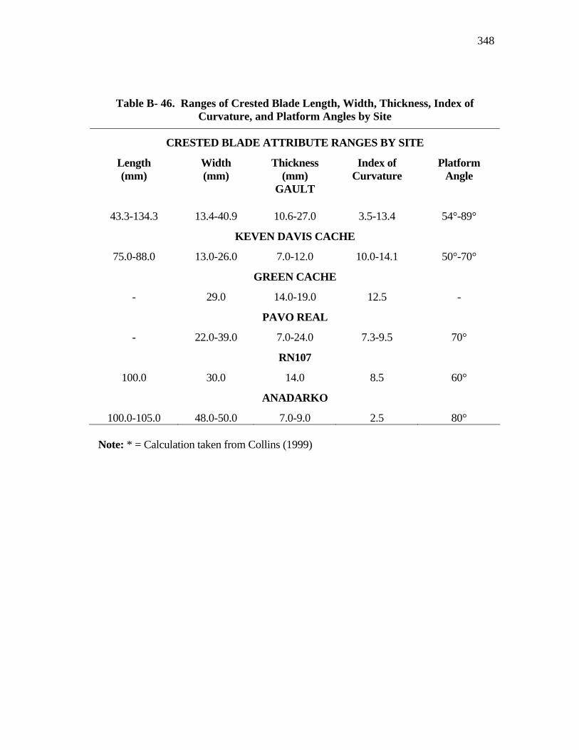
348
Table B- 46. Ranges of Crested Blade Length, Width, Thickness, Index of Curvature, and Platform Angles by Site
CRESTED BLADE ATTRIBUTE RANGES BY SITE
Length (mm)
Width (mm)
Thickness (mm)
Index of Curvature
Platform Angle
GAULT
43.3-134.3 13.4-40.9 10.6-27.0 3.5-13.4 54°-89°
KEVEN DAVIS CACHE
75.0-88.0 13.0-26.0 7.0-12.0 10.0-14.1 50°-70°
GREEN CACHE
- 29.0 14.0-19.0 12.5 -
PAVO REAL
- 22.0-39.0 7.0-24.0 7.3-9.5 70°
RN107
100.0 30.0 14.0 8.5 60°
ANADARKO
100.0-105.0 48.0-50.0 7.0-9.0 2.5 80°
Note: * = Calculation taken from Collins (1999)
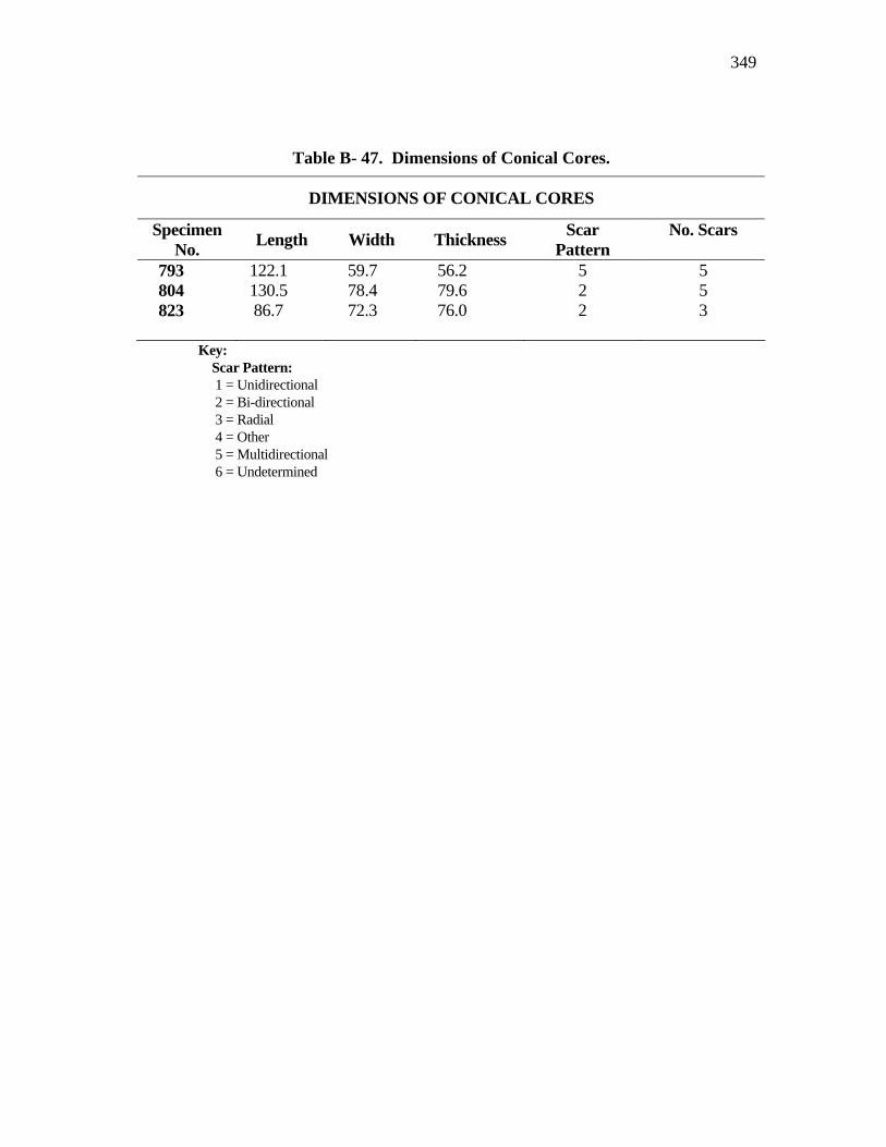
349
Table B- 47. Dimensions of Conical Cores.
DIMENSIONS OF CONICAL CORES
Specimen No. Length Width Thickness Scar
Pattern No. Scars
793 122.1 59.7 56.2 5 5 804 130.5 78.4 79.6 2 5 823 86.7 72.3 76.0 2 3
Key: Scar Pattern: 1 = Unidirectional 2 = Bi-directional 3 = Radial 4 = Other 5 = Multidirectional 6 = Undetermined
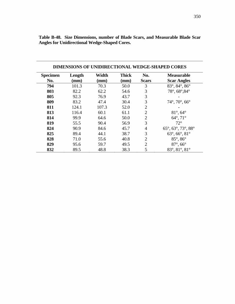
350
Table B-48. Size Dimensions, number of Blade Scars, and Measurable Blade Scar Angles for Unidirectional Wedge-Shaped Cores.
DIMENSIONS OF UNIDIRECTIONAL WEDGE-SHAPED CORES
Specimen No.
Length (mm)
Width (mm)
Thick (mm)
No. Scars
Measurable Scar Angles
794 101.3 70.3 50.0 3 83°, 84°, 86° 803 82.2 62.2 54.6 3 78°, 68°,84° 805 92.3 76.9 43.7 3 - 809 83.2 47.4 30.4 3 74°, 70°, 66° 811 124.1 107.3 52.0 2 - 813 116.4 60.1 61.1 2 81°, 64° 814 99.9 64.6 50.0 2 64°, 71° 819 55.5 90.4 56.9 3 72° 824 90.9 84.6 45.7 4 65°, 63°, 73°, 88° 825 89.4 44.1 38.7 3 63°, 66°, 81° 828 71.0 55.6 40.8 2 85°, 86° 829 95.6 59.7 49.5 2 87°, 66° 832 89.5 48.8 38.3 5 83°, 81°, 81°
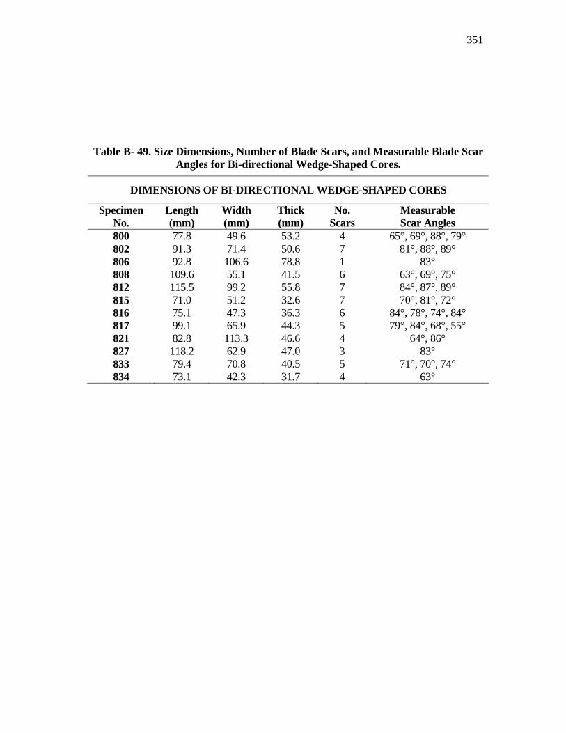
351
Table B- 49. Size Dimensions, Number of Blade Scars, and Measurable Blade Scar Angles for Bi-directional Wedge-Shaped Cores.
DIMENSIONS OF BI-DIRECTIONAL WEDGE-SHAPED CORES
Specimen No.
Length (mm)
Width (mm)
Thick (mm)
No. Scars
Measurable Scar Angles
800 77.8 49.6 53.2 4 65°, 69°, 88°, 79° 802 91.3 71.4 50.6 7 81°, 88°, 89° 806 92.8 106.6 78.8 1 83° 808 109.6 55.1 41.5 6 63°, 69°, 75° 812 115.5 99.2 55.8 7 84°, 87°, 89° 815 71.0 51.2 32.6 7 70°, 81°, 72° 816 75.1 47.3 36.3 6 84°, 78°, 74°, 84° 817 99.1 65.9 44.3 5 79°, 84°, 68°, 55° 821 82.8 113.3 46.6 4 64°, 86° 827 118.2 62.9 47.0 3 83° 833 79.4 70.8 40.5 5 71°, 70°, 74° 834 73.1 42.3 31.7 4 63°

352
Table B- 50. Size Dimensions, Number of Blade Scars, and Measurable Blade Scar Angles for Multi-directional Blade Scars.
DIMENSIONS OF MULTI-DIRECTIONAL CORES
Specimen No.
Length (mm)
Width (mm)
Thick (mm)
No. Scars
Measurable Scar Angles
790 80.9 66.8 36.8 9 80°, 84° 792 106.8 69.2 50.3 7 89°, 69°, 81°
67°, 73° 801 90.7 87.3 33.9 9 78°, 81°, 70°
67°, 81°, 81° 807 151.5 75.6 56.4 5 69°, 83° 818 58.7 50.0 32.5 5 90°, 79 °, 76° 826 66.9 63.1 39.1 6 87°, 92°
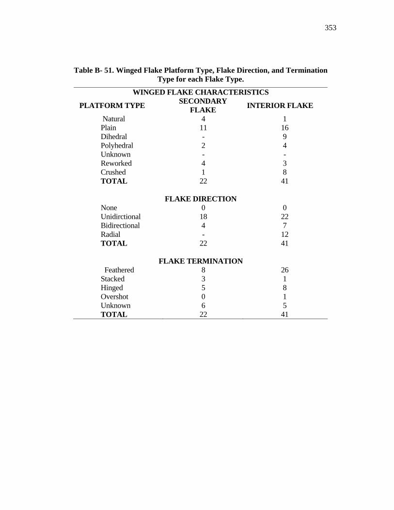
353
Table B- 51. Winged Flake Platform Type, Flake Direction, and Termination Type for each Flake Type.
WINGED FLAKE CHARACTERISTICS
PLATFORM TYPE SECONDARY FLAKE INTERIOR FLAKE
Natural 4 1 Plain 11 16 Dihedral - 9 Polyhedral 2 4 Unknown - - Reworked 4 3 Crushed 1 8 TOTAL 22 41
FLAKE DIRECTION None 0 0 Unidirctional 18 22 Bidirectional 4 7 Radial - 12 TOTAL 22 41
FLAKE TERMINATION Feathered 8 26 Stacked 3 1 Hinged 5 8 Overshot 0 1 Unknown 6 5 TOTAL 22 41
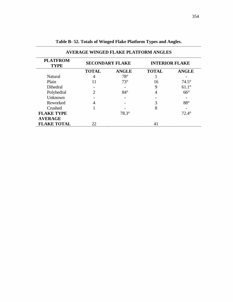
354
Table B- 52. Totals of Winged Flake Platform Types and Angles.
AVERAGE WINGED FLAKE PLATFORM ANGLES
PLATFROM TYPE SECONDARY FLAKE INTERIOR FLAKE
TOTAL ANGLE TOTAL ANGLE Natural 4 78° 1 - Plain 11 73° 16 74.5° Dihedral - - 9 61.1° Polyhedral 2 84° 4 66° Unknown - - - - Reworked 4 - 3 88° Crushed 1 - 8 - FLAKE TYPE AVERAGE
78.3° 72.4°
FLAKE TOTAL 22 41
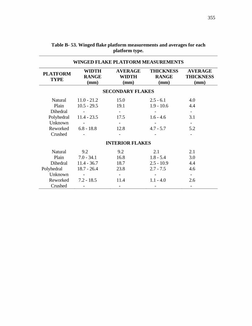
355
Table B- 53. Winged flake platform measurements and averages for each platform type.
WINGED FLAKE PLATFORM MEASUREMENTS
PLATFORM TYPE
WIDTH RANGE
(mm)
AVERAGE WIDTH
(mm)
THICKNESS RANGE
(mm)
AVERAGE THICKNESS
(mm)
SECONDARY FLAKES
Natural 11.0 - 21.2 15.0 2.5 - 6.1 4.0 Plain 10.5 - 29.5 19.1 1.9 - 10.6 4.4 Dihedral - - - - Polyhedral 11.4 - 23.5 17.5 1.6 - 4.6 3.1 Unknown - - - - Reworked 6.8 - 18.8 12.8 4.7 - 5.7 5.2 Crushed - - - -
INTERIOR FLAKES
Natural 9.2 9.2 2.1 2.1 Plain 7.0 - 34.1 16.8 1.8 - 5.4 3.0 Dihedral 11.4 - 36.7 18.7 2.5 - 10.9 4.4 Polyhedral 18.7 - 26.4 23.8 2.7 - 7.5 4.6 Unknown - - - - Reworked 7.2 - 18.5 11.4 1.1 - 4.0 2.6 Crushed - - - -
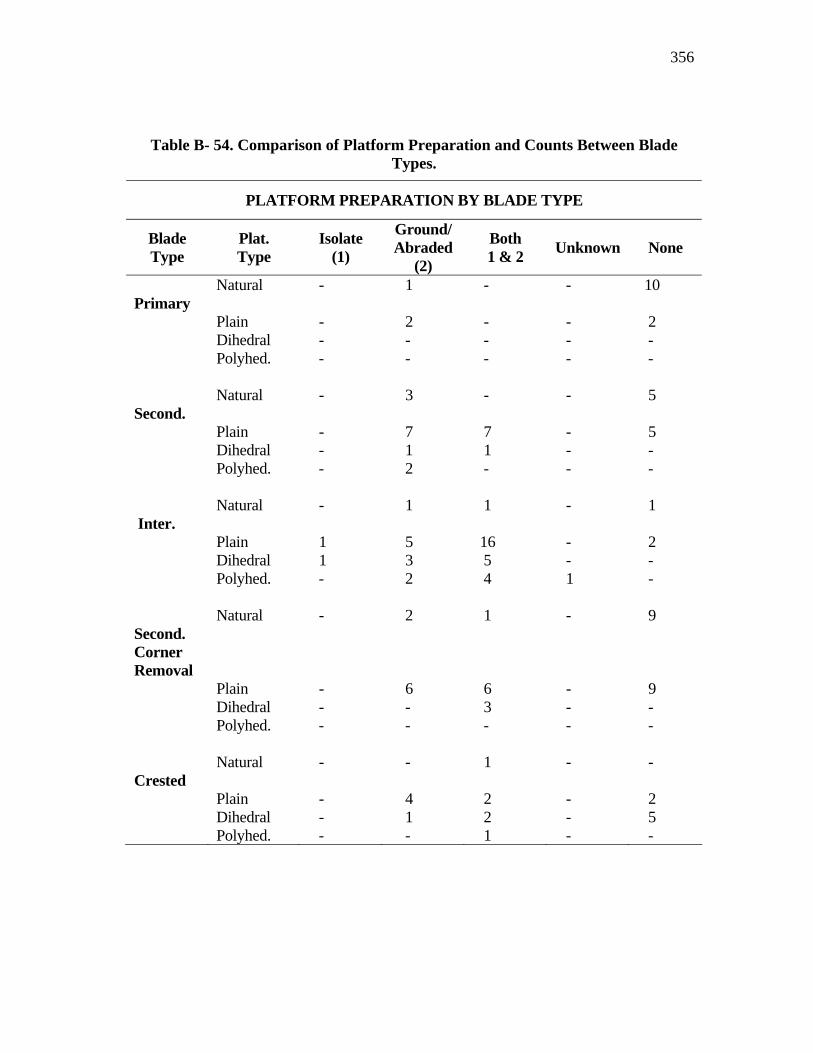
356
Table B- 54. Comparison of Platform Preparation and Counts Between Blade Types.
PLATFORM PREPARATION BY BLADE TYPE
Blade Type
Plat. Type
Isolate (1)
Ground/ Abraded
(2)
Both 1 & 2 Unknown None
Primary
Natural - 1 - - 10
Plain - 2 - - 2 Dihedral - - - - - Polyhed. - - - - - Second.
Natural - 3 - - 5
Plain - 7 7 - 5 Dihedral - 1 1 - - Polyhed. - 2 - - - Inter.
Natural - 1 1 - 1
Plain 1 5 16 - 2 Dihedral 1 3 5 - - Polyhed. - 2 4 1 - Second. Corner Removal
Natural - 2 1 - 9
Plain - 6 6 - 9 Dihedral - - 3 - - Polyhed. - - - - - Crested
Natural - - 1 - -
Plain - 4 2 - 2 Dihedral - 1 2 - 5 Polyhed. - - 1 - -
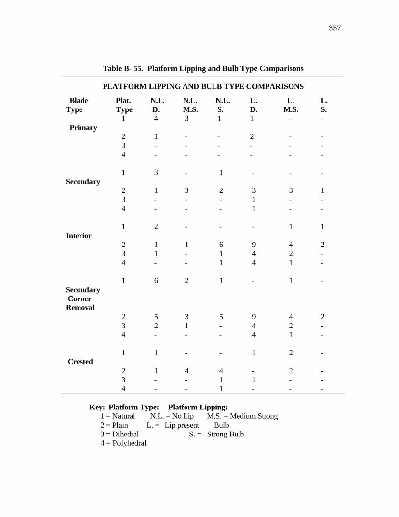
357
Table B- 55. Platform Lipping and Bulb Type Comparisons
PLATFORM LIPPING AND BULB TYPE COMPARISONS
Blade Type
Plat. Type
N.L. D.
N.L. M.S.
N.L. S.
L. D.
L. M.S.
L. S.
Primary
1 4 3 1 1 - -
2 1 - - 2 - - 3 - - - - - - 4 - - - - - - Secondary
1 3 - 1 - - -
2 1 3 2 3 3 1 3 - - - 1 - - 4 - - - 1 - - Interior
1 2 - - - 1 1
2 1 1 6 9 4 2 3 1 - 1 4 2 - 4 - - 1 4 1 - Secondary Corner Removal
1 6 2 1 - 1 -
2 5 3 5 9 4 2 3 2 1 - 4 2 - 4 - - - 4 1 - Crested
1 1 - - 1 2 -
2 1 4 4 - 2 - 3 - - 1 1 - - 4 - - 1 - - -
Key: Platform Type: Platform Lipping: 1 = Natural N.L. = No Lip M.S. = Medium Strong 2 = Plain L. = Lip present Bulb 3 = Dihedral S. = Strong Bulb 4 = Polyhedral
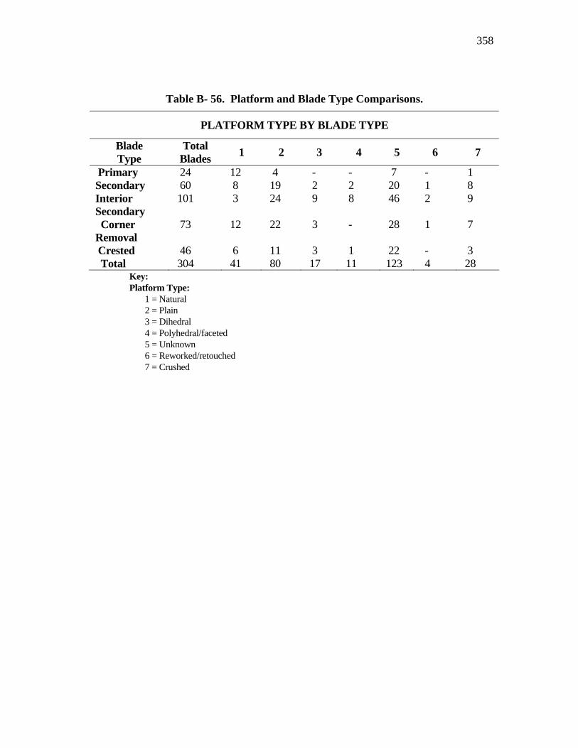
358
Table B- 56. Platform and Blade Type Comparisons.
PLATFORM TYPE BY BLADE TYPE
Blade Type
Total Blades 1 2 3 4 5 6 7
Primary 24 12 4 - - 7 - 1 Secondary 60 8 19 2 2 20 1 8 Interior 101 3 24 9 8 46 2 9 Secondary Corner Removal
73 12 22 3 - 28 1 7
Crested 46 6 11 3 1 22 - 3 Total 304 41 80 17 11 123 4 28
Key: Platform Type: 1 = Natural 2 = Plain 3 = Dihedral 4 = Polyhedral/faceted 5 = Unknown 6 = Reworked/retouched 7 = Crushed
359
VITA
Name William A. Dickens Address 200 South Haswell Dr.
Bryan, Texas 77803 E-Mail Address:
Education: Forest Technician’s Degree, Lake City Junior College, and Forest Ranger School, Lake City, Florida, 1967
B.A. Biology (Wildlife Management/Forestry), Stephen F. Austin State University, Nacogodoches, Texas, 1971
M.A. Anthropology (Archaeology), Texas A&M University, College Station, Texas, 1994
PhD. Anthropology (Archaeology), Texas A&M University, College Station, Texas, 2005
Publications: Dickens, William A., and John E. Dockall, 1993 Lithics Analysis. Archaeological Site Testing and Evaluation on the Henson Mountain Helicopter Range AWSS Project Area, Fort Hood, Texas, pp.61-82, edited by David L. Carlson. United States Army Fort Hood Archaeological Resource Management Series Research Report No. 26.
Dockall, John E., William A. Dickens, and Harry J. Shafer 1993 Getting to the Point: Some Comments on Cox and Smith's Perdiz Point Damage Analysis. Bulletin of the Texas Archeological Society, 61:301-306.
Dickens, William A., and James E. Wiederhold 2003 Some Notes on Bison, the Texas Post Oak Savanna, and the Late Prehistoric Period of Texas. Bulletin of the Texas Archaeological Society, 74:31-54.
Waters, Michael R., Mark Long, William Dickens, Sam Sweitz, Anna Lee Presley, Ian Buvit, Michelle Raisor, Bryan Mason, Hilary Standish, and Norbert Dannhaeuser. 2004
Lone Star Stalag: German Prisoners of War at Camp Hearne. Texas A&M University Press, College Station.
Dickens, William A., and William E. Moore 2004 Archaeological Survey at Musk Hog Canyon in Crockett County, Texas: The 1976 Texas Archaeological Society Field School. Bulletin of the Texas Archeological Society, 75:1-60