Embed Size (px)
Citation preview
8/20/2019 Bike Repair Manual.downarchive
http://slidepdf.com/reader/full/bike-repair-manualdownarchive 1/160
BIKE
REPAIR
MANUAL
8/20/2019 Bike Repair Manual.downarchive
http://slidepdf.com/reader/full/bike-repair-manualdownarchive 2/160
8/20/2019 Bike Repair Manual.downarchive
http://slidepdf.com/reader/full/bike-repair-manualdownarchive 3/160
BIKE
REPAIR
MANUAL C H R I S S I D W E L L S

8/20/2019 Bike Repair Manual.downarchive
http://slidepdf.com/reader/full/bike-repair-manualdownarchive 4/160
Contents
Introduction 7
GETTING TO KNOW YOUR BIKE 8
The basic bike 10
Anatomy of the bike 12
Bikes for general use 14
Specialist bikes 16
Setting up an adult’s bike 18
Setting up a child’s bike 20
CARING FOR YOUR BIKE 22
Tools 24
Workshop principles 26
Cleaning your bike 28
Lubricating your bike 30
Making routine safety checks 32
Servicing 34
Troubleshooting 36
Spotting danger signs 38
Preparing for wet weather 40
MAINTAINING
YOUR TRANSMISSION 42
Cables and shifters
How they work 44
Drop handlebar gear cables 46Straight handlebar gear cables 48
Front and rear mechs
How they work 50
Front mech 52
Rear mech 54
LONDON, NEW YORK, MUNICH,MELBOURNE, DELHI
Project Editor Richard GilbertSenior Art Editor Kevin Ryan
Art Editor Michael Duffy
Managing Editor Adèle Hayward
Managing Art Editor Karen Self
Category Publisher Stephanie Jackson
Art Director Peter Luff
DTP Designers Rajen Shah,Adam Shepherd
Production Controller Kevin Ward
Produced for Dorling Kindersley by
Editor Pip Morgan
Designer Edward Kinsey
Photographer Gerard Brown
Technical Consultant Guy Andrews
First published in 2004 by Dorling
Kindersley Limited. Revised edition
published in 2005 by Dorling Kindersley
Limited, 80 Strand, London WC2R 0RL
A Penguin Company
2 4 6 8 10 9 7 5 3 1
Copyright © 2004, 2005 DorlingKindersley Limited
Text copyright © 2004, 2005 Chris Sidwells
All rights reserved. No part of thispublication may be reproduced, storedin a retrieval system, or transmitted inany form or by any means, electronic,mechanical, photocopying, recording
or otherwise, without prior permissionof the copyright owner.
A CIP catalogue record for this book is availablefrom the British Library.
ISBN 1 4053 0253 4
Reproduced by Colourscan in Singapore
Printed and bound by Star Standard in
Singapore
See our complete catalogue at
www.dk.com
8/20/2019 Bike Repair Manual.downarchive
http://slidepdf.com/reader/full/bike-repair-manualdownarchive 5/160
Hub gears
How they work 56
Hub gear I 58
Hub gear II 60
Chain, cassette, and chainset
How they work 62
Chains 64
Cassette and freewheel 66
Chainsets 68
Bottom brackets
How they work 70Cartridge bottom bracket 72
Hollow-axle bottom bracket 74
BMX bottom bracket 76
Pedals
How they work 78
Pedal axle 80
Clipless pedals 82
Pedal cleats 84
STEERING AND WHEELS 86
Headsets
How they work 88
Threadless headset 90
Threaded headset 92
Handlebars
Straight handlebar 94
Drop handlebar 96
Hubs
How they work 98Open-bearing hub 100
Cartridge hub 102
Wheels
Quick-release wheels 104
Puncture repair 106
Spokes and rims 108
ADJUSTING YOUR BRAKES 110
Rim brakes
How they work 112
Drop handlebar brake cable 114
Straight handlebar brake cable 116
Calliper brake 118
V-brake 120
Cantilever brake 122
Alternative brake designs 124
Hub-mounted brakes
How they work 126
Cable disc brake 128Hydraulic disc brake I 130
Hydraulic disc brake II 132
Roller-brake cable 134
Coaster brake 136
TUNING YOUR SUSPENSION 138
Suspension forks
How they work 140
Front suspension 142
Coil/oil fork 144
Air/oil fork 146
Rear suspension
How it works 148
Rear suspension 150
Glossary 152
Index 154
Acknowledgments 160
8/20/2019 Bike Repair Manual.downarchive
http://slidepdf.com/reader/full/bike-repair-manualdownarchive 6/160
8/20/2019 Bike Repair Manual.downarchive
http://slidepdf.com/reader/full/bike-repair-manualdownarchive 7/160
A clean, well-maintained bike will
work efficiently and safely, and add
to your enjoyment of cycling by givingyou peace of mind.
Safety and efficiency are closely
linked. If your gears are not shifting
correctly, for instance, they will not
only affect your riding efficiency, but
also tempt you to look down at them
while riding to see what is causing
the problem. As a result, you might
take your eyes off what is happening
on the road ahead and expose yourself
to the possibility of a collision. The
Bike Repair Manual will help you
avoid such problems by demonstrating
how to maintain your bike regularly
and correctly.
Understanding technology
Modern bikes may seem complicated
and the technology that manufacturers
use may be more sophisticated than
ever. However, cycle components work,
as they have always done, according to
logical principles, so there is no reason
for you to be daunted.
Before you begin to service a
particular component of your bike,
first become familiar with the part
by turning to the relevant section.
Knowing how a part works makes it
easier to maintain.
Above all, be confident and patient
with what you are doing. Even if you
do not think of yourself as mechanically
minded, you may come to enjoy bike
maintenance after a time and will
certainly enjoy the trouble-free
cycling that rewards your efforts.
Collecting information
If you buy a new bike, make sure that
you keep the accompanying owner’smanual, so that you can refer to it
alongside this book. Do the same with
any new equipment that you buy.
If your bike is not new, obtain a
manual from a bike shop or the
manufacturer’s web site. Manuals will
help you to be aware of the particular
maintenance requirements of all the
components on your bike.
If you want to learn more about
bike mechanics, there are many
magazines available that contain
tips on specific components. However,
the large majority of people who are
simply interested in learning how to
maintain their bike will find everything
they need to know in the pages of the
Bike Repair Manual .
Using this book
The different maintenance requirements
of the most common types of bike are
listed at the beginning of the book.
These requirements are covered in the
step-by-step pages that are specific
to the components fitted to each type
of bike – for example, suspension forks
for mountain bikes.
You will also find a timetable for
servicing the parts of your bike and
a troubleshooting chart to help you
identify and solve problems. The book
helps you to spot danger signs and to
carry out routine safety checks. These
features detail what you need to do
and refer you to the relevant step-by-
step sequences to explain how to do it.
Introduction
8/20/2019 Bike Repair Manual.downarchive
http://slidepdf.com/reader/full/bike-repair-manualdownarchive 8/160
1
8/20/2019 Bike Repair Manual.downarchive
http://slidepdf.com/reader/full/bike-repair-manualdownarchive 9/160
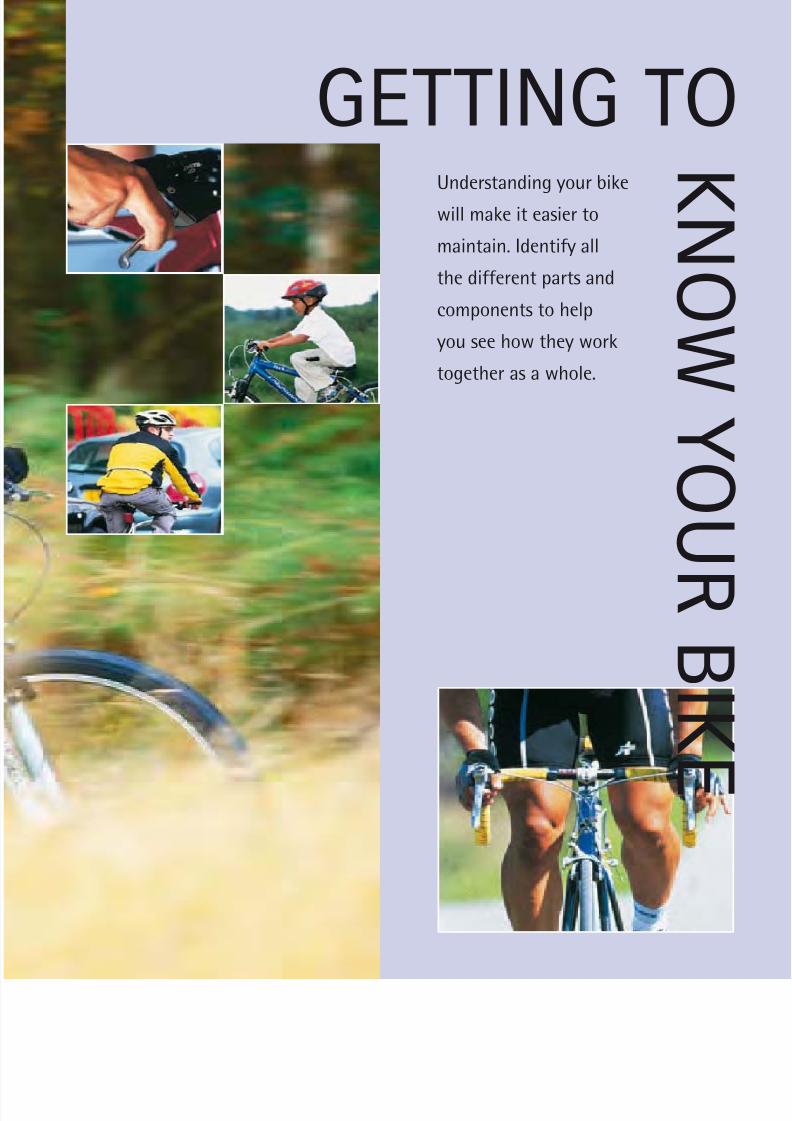
Understanding your bike
will make it easier to
maintain. Identify all
the different parts and
components to help
you see how they work
together as a whole.
GETTING TOK N O W Y O U R B I K E

8/20/2019 Bike Repair Manual.downarchive
http://slidepdf.com/reader/full/bike-repair-manualdownarchive 10/160
GETTING TO KNOW YOUR BIKE
Modern bikes, such as the hybrid bike (below ),are designed to be light and user-friendly.The parts can be grouped into different
categories, each performing a key functionin the overall operation of the bike.
The frame is the skeleton of the bike, onto which all components are fitted. The forkholds the front wheel, and connects to thehandlebar to allow the bike to be steered.The drivetrain is the system that transfers
Wheel (see pp.98–9, 104–9 )
The rim’s shape and high-tech
aluminium increases the wheel’s
strength. The wheel requires
fewer spokes, which reduces
weight and air resistance.
Hybrid bike
Advances in technology haverefined the design and improved
the performance of each category
of bike part, producing a machine
that is easy to ride and maintain.
Mech (see pp.50–5 )
Mechs are designed to
cope with the wide range
of sprocket sizes required
to climb and descend the
steepest hills.
Drivetrain (see pp.56–77)
Stiff materials maximize
the amount of power the
drivetrain transfers to the
rear wheel. A triple chainset
increases gear range and a
flexible chain allows quick,
easy gear-shifts.
Pedal (see pp.78–85 )
Toe-clips and straps give increased
power transfer to the pedals, and
allow feet to be removed quickly.
Frame (see pp.12–13 )
Improved welding techniques allow
thin-walled aluminium tubes to
provide a relatively cheap, light and
responsive frame. The thickness of
the tube walls varies to cope with
areas of increased stress.
the rider’s energy, via the pedals and cranks,to the rear wheel. It also contains a numberof cogs, known as chainrings and sprockets,
which carry the chain.The mechs (also known as derailleurs)
change gear by moving the chain on todifferent chainrings and sprockets. Theyare controlled by the gear-shifters, whichare mounted on the handlebar to allowquick and easy use by the rider. The brakes
The basic bike
10
8/20/2019 Bike Repair Manual.downarchive
http://slidepdf.com/reader/full/bike-repair-manualdownarchive 11/160
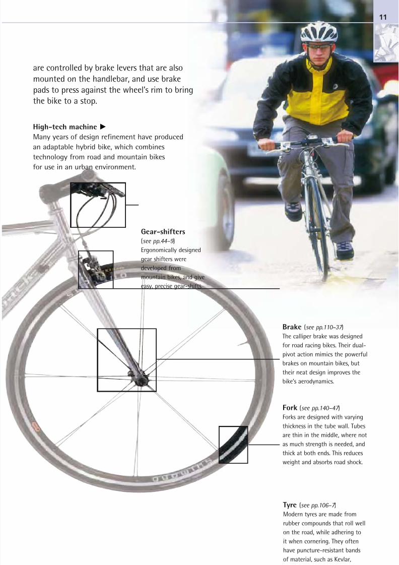
High-tech machine
Many years of design refinement have produced
an adaptable hybrid bike, which combines
technology from road and mountain bikes
for use in an urban environment.
Gear-shifters
(see pp.44–9 )
Ergonomically designed
gear shifters were
developed from
mountain bikes, and give
easy, precise gear-shifts.
Brake (see pp.110–37 )
The calliper brake was designed
for road racing bikes. Their dual-
pivot action mimics the powerful
brakes on mountain bikes, but
their neat design improves the
bike’s aerodynamics.
Fork (see pp.140–47 )
Forks are designed with varying
thickness in the tube wall. Tubes
are thin in the middle, where not
as much strength is needed, and
thick at both ends. This reduces
weight and absorbs road shock.
Tyre (see pp.106–7 )
Modern tyres are made from
rubber compounds that roll well
on the road, while adhering to
it when cornering. They often
have puncture-resistant bands
of material, such as Kevlar,
beneath the tread.
are controlled by brake levers that are alsomounted on the handlebar, and use brakepads to press against the wheel’s rim to bring
the bike to a stop.
11
8/20/2019 Bike Repair Manual.downarchive
http://slidepdf.com/reader/full/bike-repair-manualdownarchive 12/160
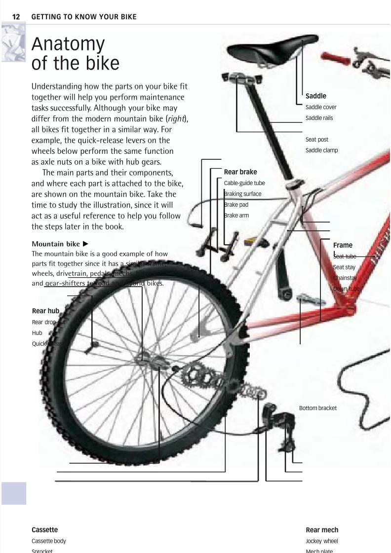
Anatomyof the bikeUnderstanding how the parts on your bike fit
together will help you perform maintenancetasks successfully. Although your bike maydiffer from the modern mountain bike (right ),all bikes fit together in a similar way. Forexample, the quick-release levers on thewheels below perform the same functionas axle nuts on a bike with hub gears.
The main parts and their components,and where each part is attached to the bike,
are shown on the mountain bike. Take thetime to study the illustration, since it willact as a useful reference to help you followthe steps later in the book.
Mountain bike
The mountain bike is a good example of how
parts fit together since it has a similar frame,
wheels, drivetrain, pedals, mechs, brakes,
and gear-shifters to road and hybrid bikes.
Rear mech
Jockey wheel
Mech plate
Barrel adjuster
Cassette
Cassette body
Sprocket
Locknut
Saddle
Saddle cover
Saddle rails
Seat post
Saddle clamp
Frame
Seat tube
Seat stay
Chainstay
Down tube
Rear brake
Cable-guide tube
Braking surface
Brake pad
Brake arm
12
Rear hub
Rear drop-out
Hub
Quick-release
Bottom bracket
GETTING TO KNOW YOUR BIKE
12
8/20/2019 Bike Repair Manual.downarchive
http://slidepdf.com/reader/full/bike-repair-manualdownarchive 13/160
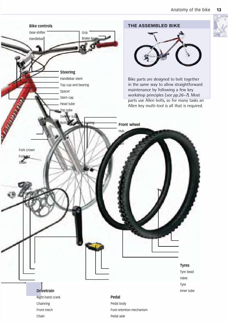
THE ASSEMBLED BIKE
Bike parts are designed to bolt togetherin the same way to allow straightforwardmaintenance by following a few keyworkshop principles (see pp.26–7 ). Mostparts use Allen bolts, so for many tasks anAllen key multi-tool is all that is required.
Drivetrain
Right-hand crank
Chainring
Front mech
Chain
Tyres
Tyre bead
Valve
Tyre
Inner tube
Pedal
Pedal body
Foot retention mechanism
Pedal axle
Front wheel
Hub
Spoke
Rim
Bike controls
Gear-shifter
Handlebar
Grip
Brake lever
13Anatomy of the bike
Steering
Handlebar stem
Top cup and bearing
Spacer
Stem cap
Head tube
Top tube
Steerer tube
Bottom cup and bearing
Fork crown
Fork leg
Slider
13
Quick-
release
8/20/2019 Bike Repair Manual.downarchive
http://slidepdf.com/reader/full/bike-repair-manualdownarchive 14/160
GETTING TO KNOW YOUR BIKE14
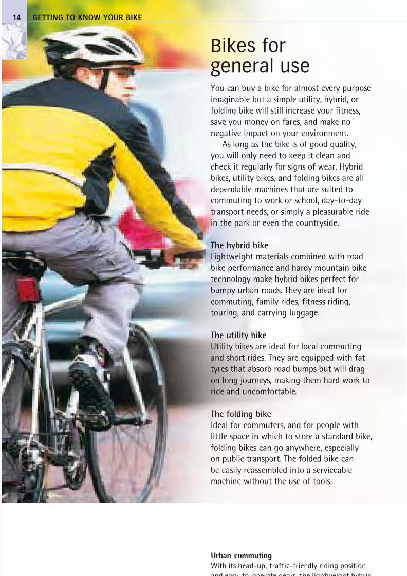
You can buy a bike for almost every purpose
imaginable but a simple utility, hybrid, orfolding bike will still increase your fitness,
save you money on fares, and make no
negative impact on your environment.
As long as the bike is of good quality,
you will only need to keep it clean and
check it regularly for signs of wear. Hybrid
bikes, utility bikes, and folding bikes are all
dependable machines that are suited to
commuting to work or school, day-to-daytransport needs, or simply a pleasurable ride
in the park or even the countryside.
The hybrid bike
Lightweight materials combined with road
bike performance and hardy mountain bike
technology make hybrid bikes perfect for
bumpy urban roads. They are ideal for
commuting, family rides, fitness riding,touring, and carrying luggage.
The utility bike
Utility bikes are ideal for local commuting
and short rides. They are equipped with fat
tyres that absorb road bumps but will drag
on long journeys, making them hard work to
ride and uncomfortable.
The folding bike
Ideal for commuters, and for people with
little space in which to store a standard bike,
folding bikes can go anywhere, especially
on public transport. The folded bike can
be easily reassembled into a serviceable
machine without the use of tools.
Bikes forgeneral use
Urban commuting
With its head-up, traffic-friendly riding position
and easy-to-operate gears, the lightweight hybrid
is ideal for urban commuting.
8/20/2019 Bike Repair Manual.downarchive
http://slidepdf.com/reader/full/bike-repair-manualdownarchive 15/160
Bikes for general use 15
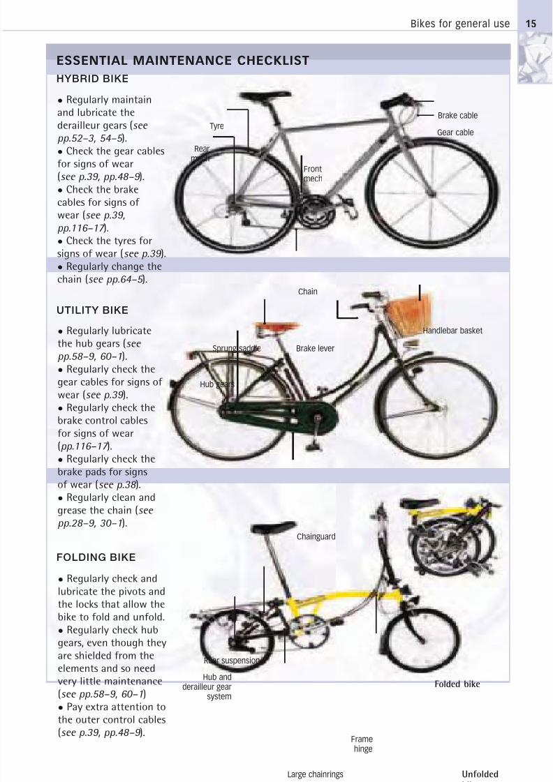
UTILITY BIKE
FOLDING BIKE
• Regularly maintainand lubricate thederailleur gears (see
pp.52–3, 54–5 ).• Check the gear cablesfor signs of wear(see p.39, pp.48–9 ).
• Check the brakecables for signs ofwear (see p.39,
pp.116–17 ).
• Check the tyres forsigns of wear (see p.39 ).
• Regularly change thechain (see pp.64–5 ).
• Regularly lubricatethe hub gears (see
pp.58–9, 60–1).
• Regularly check thegear cables for signs of wear (see p.39 ).
• Regularly check thebrake control cablesfor signs of wear(pp.116–17 ).
• Regularly check thebrake pads for signsof wear (see p.38 ).
• Regularly clean andgrease the chain (see
pp.28–9, 30–1).
• Regularly check andlubricate the pivots andthe locks that allow thebike to fold and unfold.
• Regularly check hubgears, even though theyare shielded from theelements and so need
very little maintenance(see pp.58–9, 60–1)
• Pay extra attention tothe outer control cables(see p.39, pp.48–9 ).
Tyre
Rearmech
Brake cable
Frontmech
Chain
Framehinge
Rear suspension
Large chainrings
Hub and
derailleur gearsystem
Hub gears
Brake lever
Folded bike
Unfolded
bike
ESSENTIAL MAINTENANCE CHECKLIST
Gear cable
Chainguard
Handlebar basket
Sprung saddle
HYBRID BIKE
8/20/2019 Bike Repair Manual.downarchive
http://slidepdf.com/reader/full/bike-repair-manualdownarchive 16/160
GETTING TO KNOW YOUR BIKE16
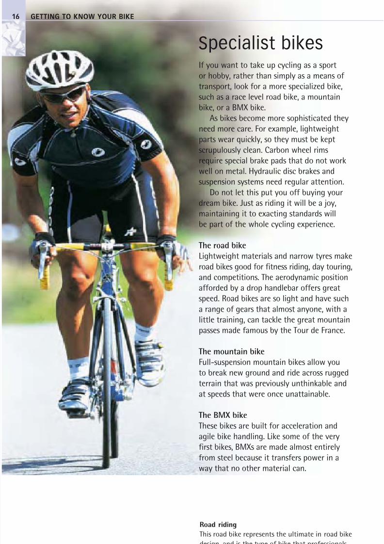
If you want to take up cycling as a sport
or hobby, rather than simply as a means of
transport, look for a more specialized bike,
such as a race level road bike, a mountainbike, or a BMX bike.
As bikes become more sophisticated they
need more care. For example, lightweight
parts wear quickly, so they must be kept
scrupulously clean. Carbon wheel rims
require special brake pads that do not work
well on metal. Hydraulic disc brakes and
suspension systems need regular attention.
Do not let this put you off buying yourdream bike. Just as riding it will be a joy,
maintaining it to exacting standards will
be part of the whole cycling experience.
The road bike
Lightweight materials and narrow tyres make
road bikes good for fitness riding, day touring,
and competitions. The aerodynamic position
afforded by a drop handlebar offers greatspeed. Road bikes are so light and have such
a range of gears that almost anyone, with a
little training, can tackle the great mountain
passes made famous by the Tour de France.
The mountain bike
Full-suspension mountain bikes allow you
to break new ground and ride across rugged
terrain that was previously unthinkable andat speeds that were once unattainable.
The BMX bike
These bikes are built for acceleration and
agile bike handling. Like some of the very
first bikes, BMXs are made almost entirely
from steel because it transfers power in a
way that no other material can.
Specialist bikes
Road riding
This road bike represents the ultimate in road bike
design, and is the type of bike that professionals
use in the Tour de France.
8/20/2019 Bike Repair Manual.downarchive
http://slidepdf.com/reader/full/bike-repair-manualdownarchive 17/160
Specialist bikes 17
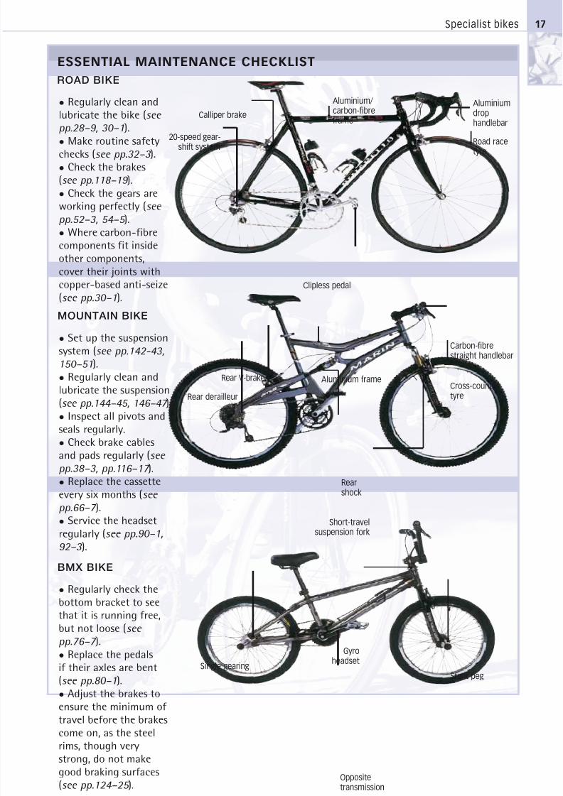
MOUNTAIN BIKE
BMX BIKE
Calliper brake
20-speed gear-shift system Road racetyre
Clipless pedal
Gyroheadset
Single gearing
Oppositetransmission
Aluminiumdrophandlebar
ESSENTIAL MAINTENANCE CHECKLIST
Rear derailleur
Rear V-brake Aluminium frameCross-countrytyre
Rearshock
Short-travelsuspension fork
ROAD BIKE
• Regularly clean andlubricate the bike (see
pp.28–9, 30–1).
• Make routine safetychecks (see pp.32–3 ).
• Check the brakes(see pp.118–19 ).
• Check the gears areworking perfectly (see
pp.52–3, 54–5 ).
• Where carbon-fibrecomponents fit insideother components,cover their joints withcopper-based anti-seize(see pp.30–1).
• Set up the suspensionsystem (see pp.142-43,
150–51).
• Regularly clean andlubricate the suspension(see pp.144–45, 146–47 ).
• Inspect all pivots andseals regularly.
• Check brake cablesand pads regularly (see
pp.38–3, pp.116–17 ).
• Replace the cassetteevery six months (see
pp.66–7 ).
• Service the headsetregularly (see pp.90–1,
92–3 ).
• Regularly check thebottom bracket to seethat it is running free,but not loose (see
pp.76–7 ).
• Replace the pedalsif their axles are bent(see pp.80–1).
• Adjust the brakes toensure the minimum of travel before the brakescome on, as the steelrims, though verystrong, do not makegood braking surfaces(see pp.124–25 ).
Carbon-fibrestraight handlebar
Aluminium/carbon-fibreframe
Stunt peg
8/20/2019 Bike Repair Manual.downarchive
http://slidepdf.com/reader/full/bike-repair-manualdownarchive 18/160
GETTING TO KNOW YOUR BIKE
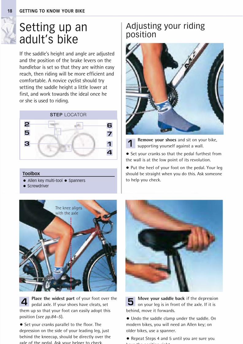
Setting up anadult’s bikeIf the saddle’s height and angle are adjusted
and the position of the brake levers on thehandlebar is set so that they are within easy
reach, then riding will be more efficient and
comfortable. A novice cyclist should try
setting the saddle height a little lower at
first, and work towards the ideal once he
or she is used to riding.
Adjusting your ridingposition
Remove your shoes and sit on your bike,
supporting yourself against a wall.
• Set your cranks so that the pedal furthest from
the wall is at the low point of its revolution.
• Put the heel of your foot on the pedal. Your leg
should be straight when you do this. Ask someone
to help you check.
Move your saddle back if the depression
on your leg is in front of the axle. If it is
behind, move it forwards.
• Undo the saddle clamp under the saddle. On
modern bikes, you will need an Allen key; on
older bikes, use a spanner.
• Repeat Steps 4 and 5 until you are sure you
have the position right.
Place the widest part of your foot over the
pedal axle. If your shoes have cleats, set
them up so that your foot can easily adopt this
position (see pp.84–5 ).
• Set your cranks parallel to the floor. The
depression on the side of your leading leg, just
behind the kneecap, should be directly over the
axle of the pedal. Ask your helper to check.
STEP LOCATOR
2
5
3
6
7
1
4
1
4 5
Toolbox
Allen key multi-tool Spanners Screwdriver
The knee aligns
with the axle
18
8/20/2019 Bike Repair Manual.downarchive
http://slidepdf.com/reader/full/bike-repair-manualdownarchive 19/160
Setting up an adult’s bike
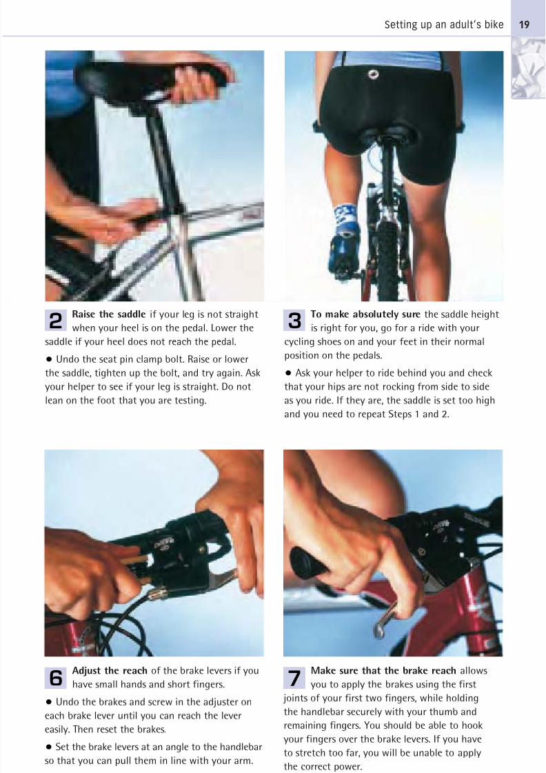
Raise the saddle if your leg is not straight
when your heel is on the pedal. Lower the
saddle if your heel does not reach the pedal.
• Undo the seat pin clamp bolt. Raise or lower
the saddle, tighten up the bolt, and try again. Ask
your helper to see if your leg is straight. Do not
lean on the foot that you are testing.
To make absolutely sure the saddle height
is right for you, go for a ride with your
cycling shoes on and your feet in their normal
position on the pedals.
• Ask your helper to ride behind you and check
that your hips are not rocking from side to side
as you ride. If they are, the saddle is set too high
and you need to repeat Steps 1 and 2.
Adjust the reach of the brake levers if you
have small hands and short fingers.
• Undo the brakes and screw in the adjuster on
each brake lever until you can reach the lever
easily. Then reset the brakes.
• Set the brake levers at an angle to the handlebar
so that you can pull them in line with your arm.
Make sure that the brake reach allows
you to apply the brakes using the first
joints of your first two fingers, while holding
the handlebar securely with your thumb and
remaining fingers. You should be able to hook
your fingers over the brake levers. If you have
to stretch too far, you will be unable to apply
the correct power.
19
2 3
6 7
8/20/2019 Bike Repair Manual.downarchive
http://slidepdf.com/reader/full/bike-repair-manualdownarchive 20/160
GETTING TO KNOW YOUR BIKE
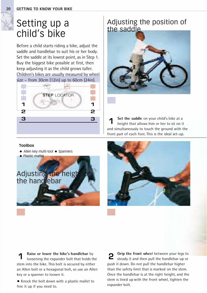
Setting up achild’s bikeBefore a child starts riding a bike, adjust the
saddle and handlebar to suit his or her body.Set the saddle at its lowest point, as in Step 1.Buy the biggest bike possible at first, thenkeep adjusting it as the child grows taller.Children’s bikes are usually measured by wheelsize – from 30cm (12in) up to 60cm (24in).
Adjusting the position of the saddle
Set the saddle on your child’s bike at a
height that allows him or her to sit on it
and simultaneously to touch the ground with the
front part of each foot. This is the ideal set-up.
Raise or lower the bike’s handlebar by
loosening the expander bolt that holds the
stem into the bike. This bolt is secured by either
an Allen bolt or a hexagonal bolt, so use an Allen
key or a spanner to loosen it.
• Knock the bolt down with a plastic mallet to
free it up if you need to.
Grip the front wheel between your legs to
steady it and then pull the handlebar up or
push it down. Do not pull the handlebar higher
than the safety limit that is marked on the stem.
Once the handlebar is at the right height, and the
stem is lined up with the front wheel, tighten the
expander bolt.
20
1
21
STEP LOCATOR
1
2
3
1
2
3
Toolbox
Allen key multi-tool Spanners
Plastic mallet
Adjusting the height of the handlebar

8/20/2019 Bike Repair Manual.downarchive
http://slidepdf.com/reader/full/bike-repair-manualdownarchive 21/160
Setting up a child’s bike
Loosen the seat pin clamp – it either has a
quick-release lever or a nut-and-bolt fixing
that requires a spanner. Either pull the saddle up
or push it down to the required height.
Move the saddle forwards or backwards
by loosening the nut that secures the seat
clamp. Tighten the nut again, but be sure that the
saddle is horizontal to the ground.
Adjust the saddle
and handlebar still
further if you need to, so
that your child can sit in
the ideal riding position –
neither too upright, nor
too stretched.
21
2 3
3

8/20/2019 Bike Repair Manual.downarchive
http://slidepdf.com/reader/full/bike-repair-manualdownarchive 22/160
2
8/20/2019 Bike Repair Manual.downarchive
http://slidepdf.com/reader/full/bike-repair-manualdownarchive 23/160
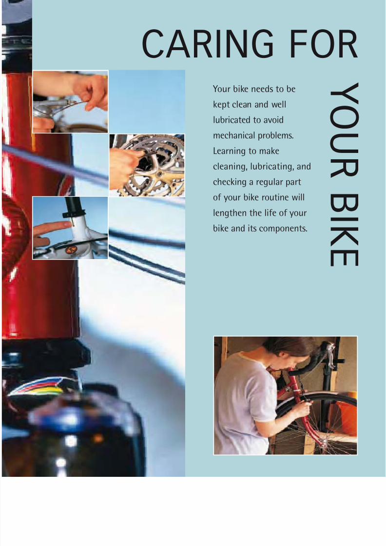
CARING FOR Your bike needs to be
kept clean and well
lubricated to avoid
mechanical problems.
Learning to make
cleaning, lubricating, and
checking a regular part
of your bike routine will
lengthen the life of your
bike and its components.
Y O U R
B I K E
8/20/2019 Bike Repair Manual.downarchive
http://slidepdf.com/reader/full/bike-repair-manualdownarchive 24/160
If you are going to regularly maintain and
repair your bike, you will need to buy a
toolkit or assemble your own. The tools
shown opposite will enable you to carry outall the essential repairs and to maintain your
bike at peak performance. Add other tools
as the need arises when specific parts of
your bike require maintenance or replacing.
However, try to follow a few general
principles when using the tools.
When using tools on a bike, especially
lightweight bikes, you need a delicate touch.
If you are used to working on cars, then useless force when dealing with your bike. Nuts
and bolts only need to be tight; if you over-
tighten them they will shear. If in doubt, buy
torque gauges that accurately measure the
correct level of tightness on a bike’s nuts
and bolts. See the component manufacturers’
instructions for recommended torque
settings. In fact, it is essential to keep all
the instructions that come with your bike,tools, and any components you buy.
Buy the best-quality, precision-made
tools. They will last for many years if you
look after them. Cheap tools will bend and
become chipped, making it impossible to
carry out some maintenance jobs properly.
They could even damage the components
that you work on.
Tools
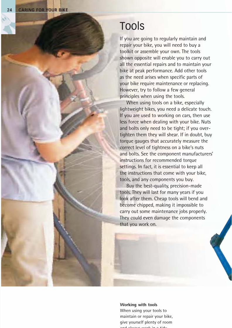
Working with tools
When using your tools to
maintain or repair your bike,
give yourself plenty of room
and always work in a tidy,
well-lit environment.
24 CARING FOR YOUR BIKE
8/20/2019 Bike Repair Manual.downarchive
http://slidepdf.com/reader/full/bike-repair-manualdownarchive 25/160
Tools 25
Workstand
Trackpump
Shock pump
Chainwhip
Crankpuller
Hollow-axlecup tool
Hollow-axle crank cap tool
Allen keymulti-tool
Allen keys2-10mm
Chaintool
Long-nosedpliers
(narrow)
Long-nosedpliers(wide)
Pegspanner
Spanner
Crank-bolt
remover
Cassette remover
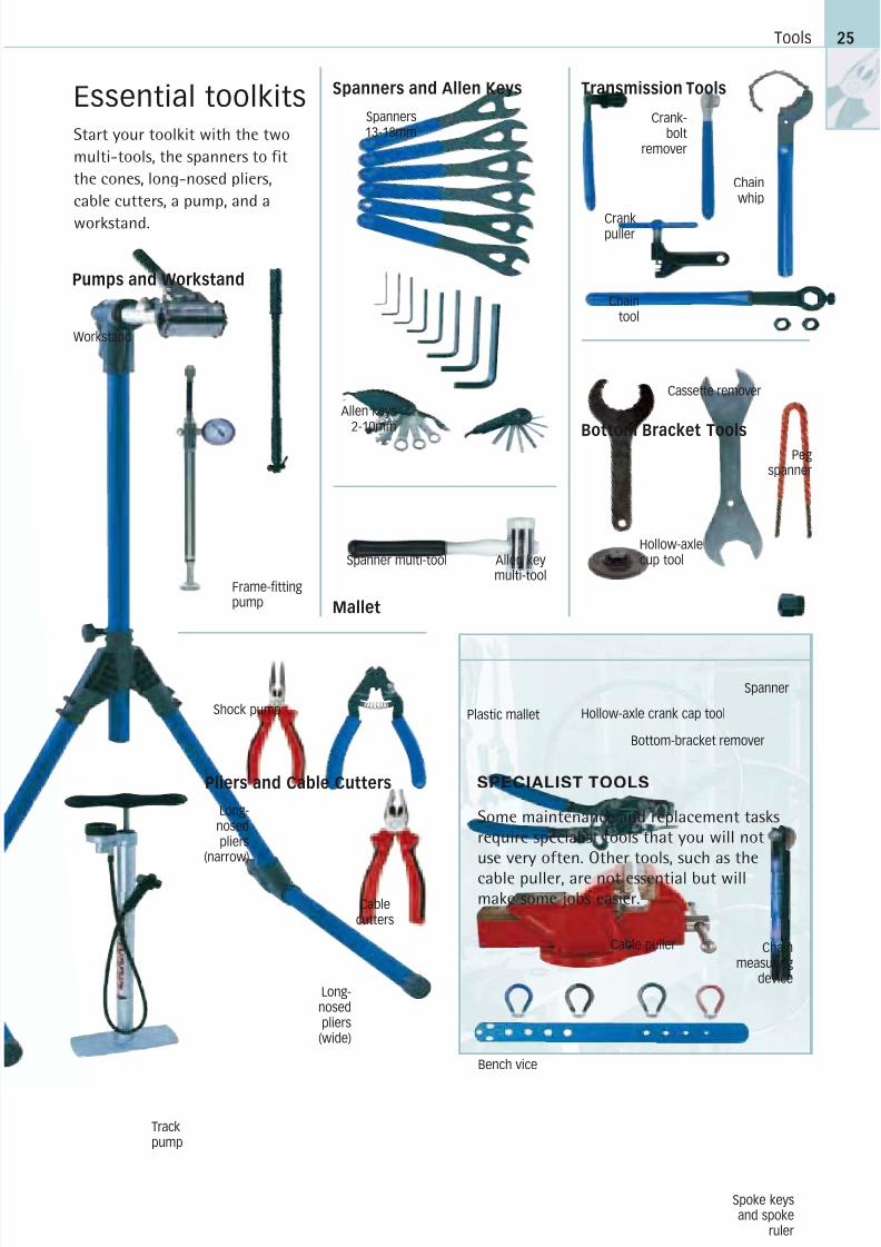
SPECIALIST TOOLS
Some maintenance and replacement tasks
require specialist tools that you will not
use very often. Other tools, such as the
cable puller, are not essential but willmake some jobs easier.
Cable puller
Bench vice
Spoke keysand spoke
ruler
Chainmeasuring
device
Essential toolkits
Start your toolkit with the two
multi-tools, the spanners to fit
the cones, long-nosed pliers,
cable cutters, a pump, and a
workstand.
Plastic mallet
Cablecutters
Pumps and Workstand
Spanners and Allen Keys
Bottom Bracket Tools
Mallet
Transmission Tools
Pliers and Cable Cutters
Frame-fittingpump
Bottom-bracket remover
Spanner multi-tool
Spanners13-18mm
8/20/2019 Bike Repair Manual.downarchive
http://slidepdf.com/reader/full/bike-repair-manualdownarchive 26/160
CARING FOR YOUR BIKE
Workshop principles
Cutting cable outersUsing a spanner
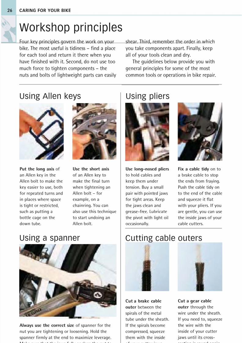
Put the long axis of
an Allen key in the
Allen bolt to make thekey easier to use, both
for repeated turns and
in places where space
is tight or restricted,
such as putting a
bottle cage on the
down tube.
Use the short axis
of an Allen key to
make the final turnwhen tightening an
Allen bolt – for
example, on a
chainring. You can
also use this technique
to start undoing an
Allen bolt.
Always use the correct size of spanner for the
nut you are tightening or loosening. Hold the
spanner firmly at the end to maximize leverage.
Make sure that the jaws fully enclose the nut to
prevent it from slipping.
26
Four key principles govern the work on your
bike. The most useful is tidiness – find a place
for each tool and return it there when you
have finished with it. Second, do not use toomuch force to tighten components – the
nuts and bolts of lightweight parts can easily
Use long-nosed pliers
to hold cables and
keep them undertension. Buy a small
pair with pointed jaws
for tight areas. Keep
the jaws clean and
grease-free. Lubricate
the pivot with light oil
occasionally.
Fix a cable tidy on to
a brake cable to stop
the ends from fraying.Push the cable tidy on
to the end of the cable
and squeeze it flat
with your pliers. If you
are gentle, you can use
the inside jaws of your
cable cutters.
Cut a brake cableouter between the
spirals of the metal
tube under the sheath.
If the spirals become
compressed, squeeze
them with the inside
of your cutter jaws
until they are round.
Cut a gear cableouter through the
wire under the sheath.
If you need to, squeeze
the wire with the
inside of your cutter
jaws until its cross-
section is round again.
Using Allen keys Using pliers
shear. Third, remember the order in which
you take components apart. Finally, keep
all of your tools clean and dry.
The guidelines below provide you withgeneral principles for some of the most
common tools or operations in bike repair.
8/20/2019 Bike Repair Manual.downarchive
http://slidepdf.com/reader/full/bike-repair-manualdownarchive 27/160
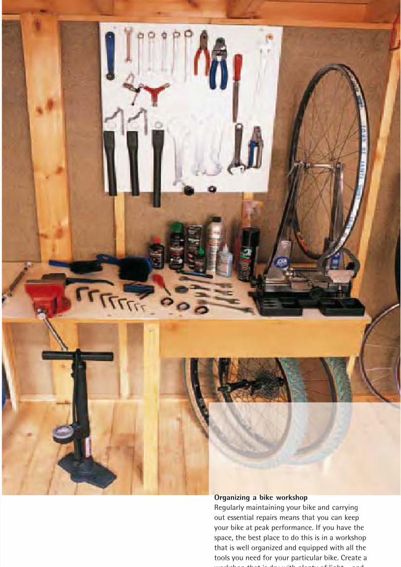
Organizing a bike workshopRegularly maintaining your bike and carrying
out essential repairs means that you can keep
your bike at peak performance. If you have the
space, the best place to do this is in a workshop
that is well organized and equipped with all the
tools you need for your particular bike. Create a
workshop that is dry with plenty of light – and
follow the four key workshop principles.
8/20/2019 Bike Repair Manual.downarchive
http://slidepdf.com/reader/full/bike-repair-manualdownarchive 28/160
CARING FOR YOUR BIKE28
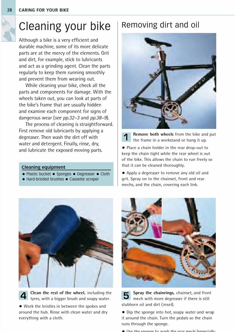
Cleaning your bikeAlthough a bike is a very efficient anddurable machine, some of its more delicateparts are at the mercy of the elements. Grit
and dirt, for example, stick to lubricantsand act as a grinding agent. Clean the partsregularly to keep them running smoothlyand prevent them from wearing out.
While cleaning your bike, check all theparts and components for damage. With thewheels taken out, you can look at parts of the bike’s frame that are usually hiddenand examine each component for signs of
dangerous wear (see pp.32–3 and pp.38–9 ).The process of cleaning is straightforward.
First remove old lubricants by applying adegreaser. Then wash the dirt off withwater and detergent. Finally, rinse, dry,and lubricate the exposed moving parts.
Removing dirt and oil
Remove both wheels from the bike and put
the frame in a workstand or hang it up.
• Place a chain holder in the rear drop-out to
keep the chain tight while the rear wheel is out
of the bike. This allows the chain to run freely so
that it can be cleaned thoroughly.
• Apply a degreaser to remove any old oil andgrit. Spray on to the chainset, front and rear
mechs, and the chain, covering each link.
1
Spray the chainrings, chainset, and front
mech with more degreaser if there is still
stubborn oil and dirt (inset ).
• Dip the sponge into hot, soapy water and wrap
it around the chain. Turn the pedals so the chain
runs through the sponge.
• Use the sponge to wash the rear mech (especially
its jockey wheels), the front mech, and chainrings.
5Clean the rest of the wheel, including the
tyres, with a bigger brush and soapy water.
• Work the bristles in between the spokes and
around the hub. Rinse with clean water and dry
everything with a cloth.
4
Cleaning equipment
Plastic bucket Sponges Degreaser Cloth Hard-bristled brushes Cassette scraper
8/20/2019 Bike Repair Manual.downarchive
http://slidepdf.com/reader/full/bike-repair-manualdownarchive 29/160
Cleaning your bike 29
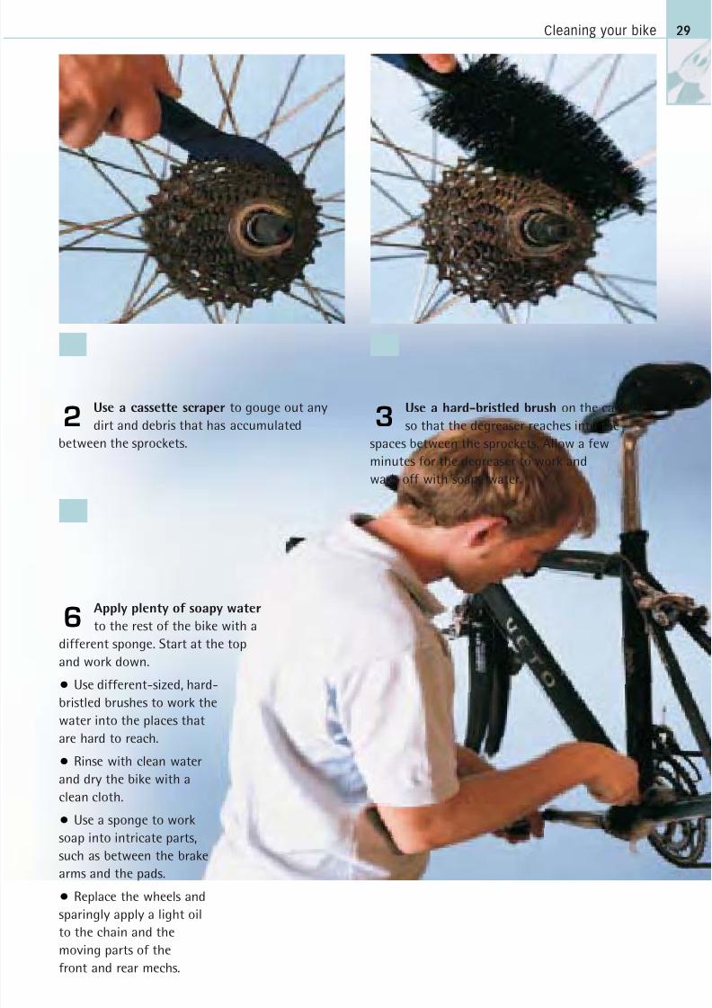
Apply plenty of soapy water
to the rest of the bike with a
different sponge. Start at the top
and work down.
• Use different-sized, hard-
bristled brushes to work thewater into the places that
are hard to reach.
• Rinse with clean water
and dry the bike with a
clean cloth.
• Use a sponge to work
soap into intricate parts,
such as between the brake
arms and the pads.
• Replace the wheels and
sparingly apply a light oil
to the chain and the
moving parts of the
front and rear mechs.
6
Use a hard-bristled brush on the cassette
so that the degreaser reaches into the
spaces between the sprockets. Allow a few
minutes for the degreaser to work and
wash off with soapy water.
3Use a cassette scraper to gouge out any
dirt and debris that has accumulated
between the sprockets.
2
8/20/2019 Bike Repair Manual.downarchive
http://slidepdf.com/reader/full/bike-repair-manualdownarchive 30/160
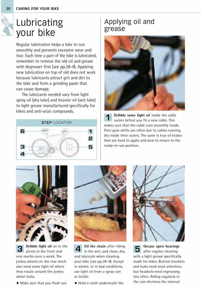
Dribble some light oil inside the cable
outers before you fit a new cable. This
makes sure that the cable runs smoothly inside.
Poor gear-shifts are often due to cables running
dry inside their outers. The same is true of brakes
that are hard to apply and slow to return to the
ready-to-use position.
6
3
4
1
2
5
STEP LOCATOR
CARING FOR YOUR BIKE
Lubricating your bike
Regular lubrication helps a bike to run
smoothly and prevents excessive wear andtear. Each time a part of the bike is lubricated,remember to remove the old oil and greasewith degreaser first (see pp.28–9 ). Applyingnew lubrication on top of old does not workbecause lubricants attract grit and dirt tothe bike and form a grinding paste thatcan cause damage.
The lubricants needed vary from light
spray oil (dry lube) and heavier oil (wet lube)to light grease manufactured specifically forbikes and anti-seize compounds.
Grease open bearings
after regular cleaning
with a light grease specifically
made for bikes. Bottom brackets
and hubs need most attention,
but headsets need regreasing
less often. Riding regularly in
the rain shortens the interval
between lubrications.
Dribble light oil on to the
pivots in the front and
rear mechs once a week. The
jockey wheels on the rear mech
also need some light oil where
they rotate around the jockey
wheel bolts.
• Make sure that you flush out
any old oil with degreaser first.
Oil the chain after riding
in the wet, and clean, dry,
and lubricate when cleaning
your bike (see pp.28–9 ). Except
in winter, or in bad conditions,
use light oil from a spray can
or bottle.
• Hold a cloth underneath the
chain to catch any excess oil.
30
Applying oil andgrease
1
543
8/20/2019 Bike Repair Manual.downarchive
http://slidepdf.com/reader/full/bike-repair-manualdownarchive 31/160
Lubricating your bike
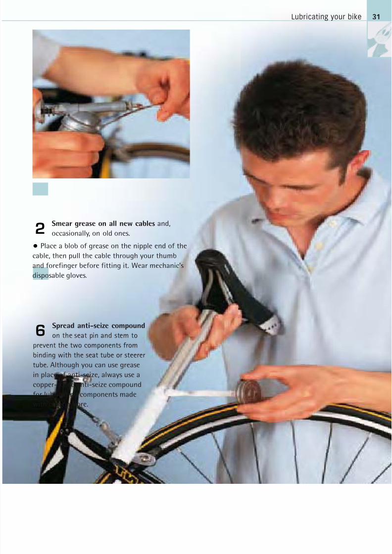
Spread anti-seize compound
on the seat pin and stem to
prevent the two components from
binding with the seat tube or steerer
tube. Although you can use grease
in place of anti-seize, always use a
copper-based anti-seize compoundfor lubricating components made
with carbon fibre.
31
6
Smear grease on all new cables and,
occasionally, on old ones.
• Place a blob of grease on the nipple end of the
cable, then pull the cable through your thumb
and forefinger before fitting it. Wear mechanic’s
disposable gloves.
2
8/20/2019 Bike Repair Manual.downarchive
http://slidepdf.com/reader/full/bike-repair-manualdownarchive 32/160
STEP LOCATOR
4
3
CARING FOR YOUR BIKE32
Making routinesafety checksEvery week or so, check the bike frame for
signs of wear. Before going for a ride, runthrough a few checks to reduce the chances
of a mechanical failure: brakes that cease to
work, a loose handlebar, a tyre blow-out, or
slipping gears. The checks will help to avoid
many of the accidents caused by equipment
failures. Safety checks help the management
of a bike, allowing the replacement of parts
in good time or the completion of non-
urgent maintenance work.
Making frame checks
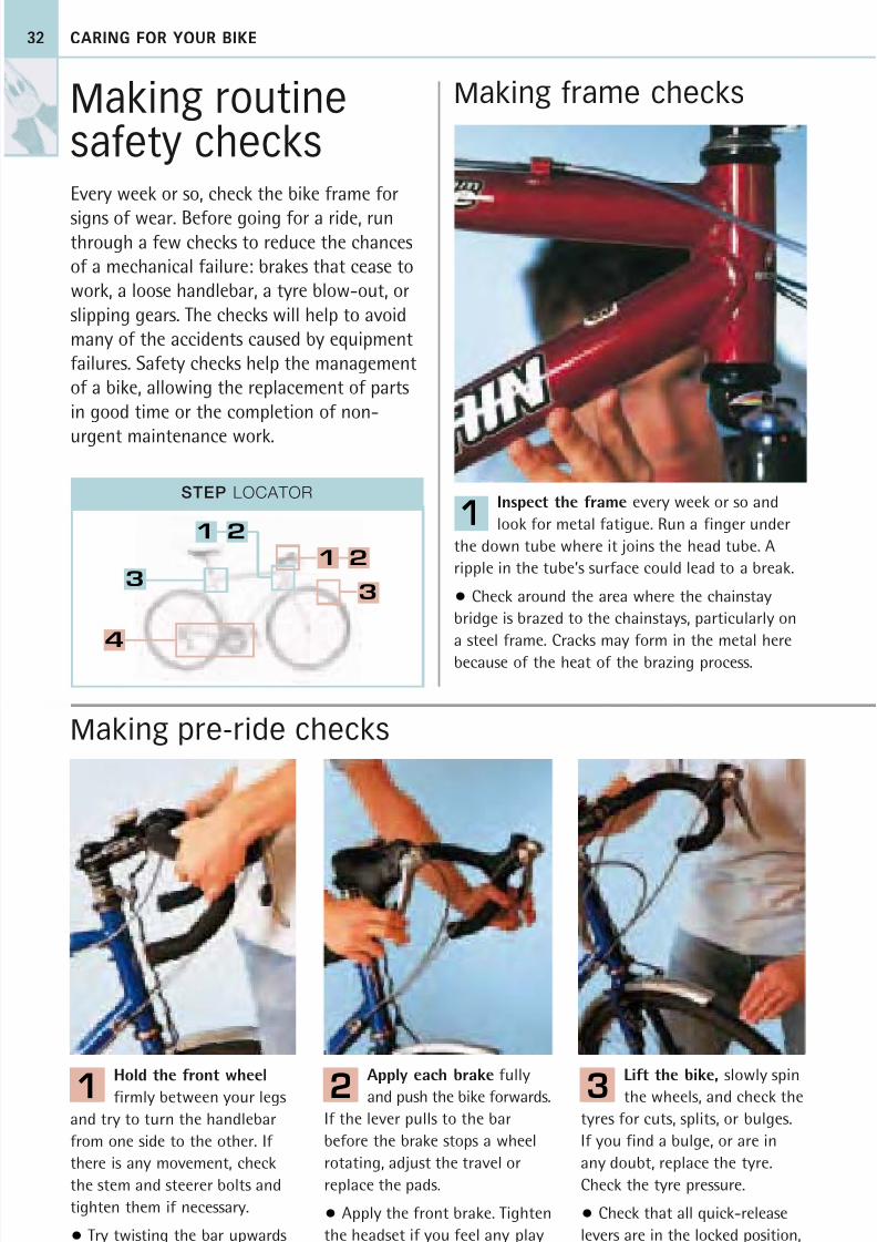
Inspect the frame every week or so and
look for metal fatigue. Run a finger under
the down tube where it joins the head tube. A
ripple in the tube’s surface could lead to a break.
• Check around the area where the chainstay
bridge is brazed to the chainstays, particularly on
a steel frame. Cracks may form in the metal here
because of the heat of the brazing process.
1
Apply each brake fully
and push the bike forwards.
If the lever pulls to the bar
before the brake stops a wheel
rotating, adjust the travel or
replace the pads.
• Apply the front brake. Tighten
the headset if you feel any play
in the steerer assembly.
2
Lift the bike, slowly spin
the wheels, and check the
tyres for cuts, splits, or bulges.
If you find a bulge, or are in
any doubt, replace the tyre.
Check the tyre pressure.
• Check that all quick-release
levers are in the locked position,
and wheel nuts are tight.
3
Hold the front wheel
firmly between your legs
and try to turn the handlebar
from one side to the other. If
there is any movement, check
the stem and steerer bolts and
tighten them if necessary.
• Try twisting the bar upwards
to look for rotational movement.
1
Making pre-ride checks
1 2
1 2
3
8/20/2019 Bike Repair Manual.downarchive
http://slidepdf.com/reader/full/bike-repair-manualdownarchive 33/160
Making routine safety checks 33
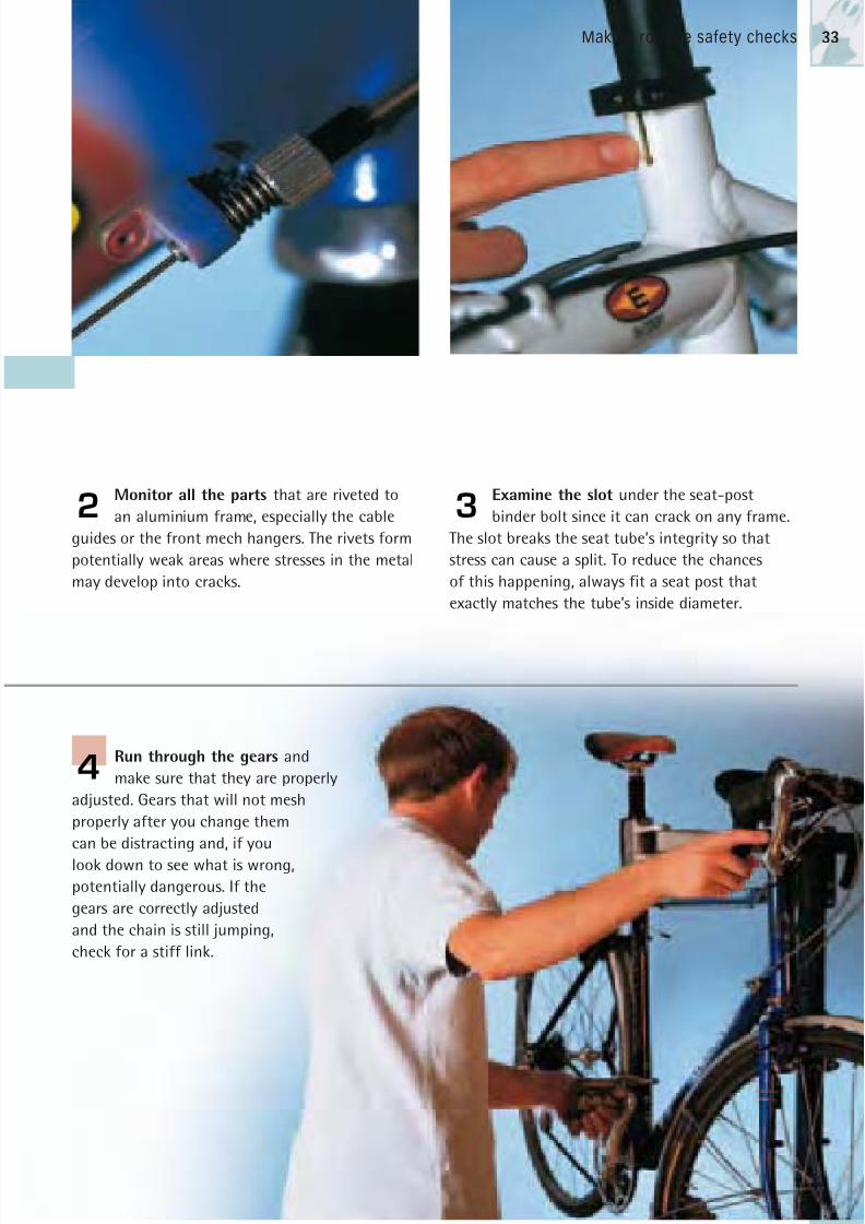
Monitor all the parts that are riveted to
an aluminium frame, especially the cable
guides or the front mech hangers. The rivets form
potentially weak areas where stresses in the metal
may develop into cracks.
2
Run through the gears and
make sure that they are properly
adjusted. Gears that will not mesh
properly after you change them
can be distracting and, if you
look down to see what is wrong,
potentially dangerous. If the
gears are correctly adjusted
and the chain is still jumping,
check for a stiff link.
4
Examine the slot under the seat-post
binder bolt since it can crack on any frame.
The slot breaks the seat tube’s integrity so that
stress can cause a split. To reduce the chances
of this happening, always fit a seat post that
exactly matches the tube’s inside diameter.
3
8/20/2019 Bike Repair Manual.downarchive
http://slidepdf.com/reader/full/bike-repair-manualdownarchive 34/160
CARING FOR YOUR BIKE34
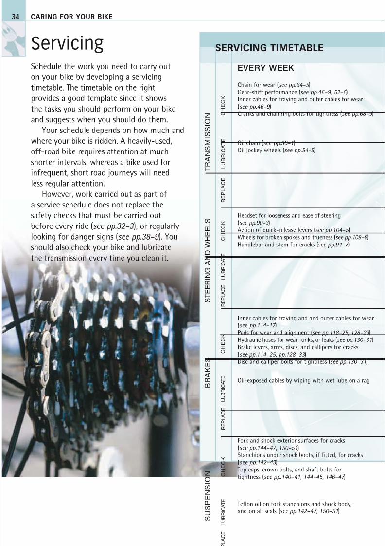
ServicingSchedule the work you need to carry outon your bike by developing a servicingtimetable. The timetable on the right
provides a good template since it showsthe tasks you should perform on your bikeand suggests when you should do them.
Your schedule depends on how much andwhere your bike is ridden. A heavily-used,off-road bike requires attention at muchshorter intervals, whereas a bike used forinfrequent, short road journeys will needless regular attention.
However, work carried out as part ofa service schedule does not replace thesafety checks that must be carried outbefore every ride (see pp.32–3 ), or regularlylooking for danger signs (see pp.38–9 ). Youshould also check your bike and lubricatethe transmission every time you clean it.
Chain for wear (see pp.64–5 )Gear-shift performance (see pp.46–9, 52–5 )Inner cables for fraying and outer cables for wear(see pp.46–9 )Cranks and chainring bolts for tightness (see pp.68–9 )
Oil chain (see pp.30–1)Oil jockey wheels (see pp.54-5 )
Headset for looseness and ease of steering(see pp.90–3 )Action of quick-release levers (see pp.104–5 )Wheels for broken spokes and trueness (see pp.108–9 )Handlebar and stem for cracks (see pp.94–7 )
Inner cables for fraying and and outer cables for wear(see pp.114–17 )Pads for wear and alignment (see pp.118–25, 128–29 )Hydraulic hoses for wear, kinks, or leaks (see pp.130–31)Brake levers, arms, discs, and callipers for cracks(see pp.114–25, pp.128–33 )Disc and calliper bolts for tightness (see pp.130–31)
Oil-exposed cables by wiping with wet lube on a rag
Fork and shock exterior surfaces for cracks(see pp.144–47, 150–51)Stanchions under shock boots, if fitted, for cracks(see pp.142–43 )Top caps, crown bolts, and shaft bolts for
tightness (see pp.140–41, 144–45, 146–47 )
Teflon oil on fork stanchions and shock body,and on all seals (see pp.142–47, 150–51)
S U S P E N S I O
N
B R
A K E S
T R A N S M I S S I O N
S T E E
R I N G A N D W H E E L S
C H E C K
L U B R I C A T E
R E P L A C E
C H E C K
L U B R I C A T E
R E P L A C E
SERVICING TIMETABLE
EVERY WEEK
C H E C K
L U B R I C A T E
C H E C K
L U B R I C A T E
R E P L A C E
R E P L
A C E

8/20/2019 Bike Repair Manual.downarchive
http://slidepdf.com/reader/full/bike-repair-manualdownarchive 35/160
Servicing 35
Bottom bracket for smooth running, play, and bent axle (see
pp.72–7 )Pedals for play, and clipless pedals for play and release action(see pp.80–3 )Rear mech pivots for play (see pp.54–5 )Sprocket and chainring teeth for wear (see pp.66–9 )
Oil mech pivots (see pp.30–1)Oil and grease inner and outer cables (see pp.30–1)Oil clipless pedal release mechanisms (see pp.40–1)
Chain on a heavily used bike (see pp.40–1, 64–5 )
Hubs for play on axles, roughness, or tight spots(see pp.100–3 )Rubber seals on hubs for splits (see pp.100–3 )Covers, if fitted, on headsets (see pp.40–1)
Oil the seals on hubs (see pp.100–3 )
Discs for wear and callipers for alignment (see pp.130–31)Coaster brake action and chain tension (see pp.136–37 )
Grease inner cables and oil inside outer cables (see pp.30–1,114–17 )
Brake pads of heavily used mountain bikes (see pp.120–23 )
Fork and shock for play (see pp.142–47, 150–51)Fork stanchions to see if oil line visible (see pp.142–47 )Fork and shock seals for cracks and slackness (see pp.142–47,
150–51).Play, absence of oil lines, and cracked seals are all evidence of
worn seals, which should be replaced by a qualified technician.Fork and shock sag (see pp.142–43, 150–51)
Tip bike upside down and store overnight so oil canredistribute in fork
Freehub body and freewheel for play (see pp.66–7 )Rear mech frame fixing bolt for play (see pp.54–5 )Cleats for wear (see pp.84–5 )Jockey wheels for wear (see pp.54–5 )
Oil in hub gear, if equipped with oil port (see pp.58–9 )Grease bearings in pedals (see pp.80–1)
Chain (see pp.64–5 )Inner and outer cables (see pp.46–9 )Sprockets on a heavily used bike (see pp.66–7 )
Bearings in open-bearing hubs for wear (see pp.100–1)Bearings and bearing surfaces in headsets for wear(see pp.90–3 )
Grease open-bearing hubs (see pp.100–1)Grease headsets (see pp.90–3 )
Handlebar tape and grips (see pp.94–7 )
Grease brake bosses (see pp.122–23 )
Inner and outer cables (see pp.114–17 )
Fork steerer for cracks, by removing the headset(see pp.90–3 )
Fork oil (see pp.144–47 )Seals on forks and shocks, as part of bi-annual serviceby qualified technician
EVERY MONTH EVERY SIX MONTHS
8/20/2019 Bike Repair Manual.downarchive
http://slidepdf.com/reader/full/bike-repair-manualdownarchive 36/160
CARING FOR YOUR BIKE
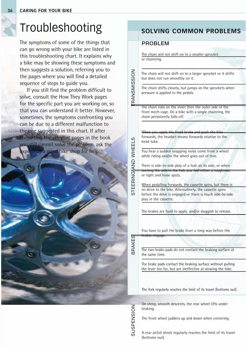
TroubleshootingThe symptoms of some of the things thatcan go wrong with your bike are listed inthis troubleshooting chart. It explains why
a bike may be showing these symptoms andthen suggests a solution, referring you tothe pages where you will find a detailedsequence of steps to guide you.
If you still find the problem difficult tosolve, consult the How They Work pagesfor the specific part you are working on, sothat you can understand it better. However,sometimes, the symptoms confronting you
can be due to a different malfunction tothe one suggested in this chart. If afterconsulting the relevant pages in the bookyou still cannot solve the problem, ask theexperts at a good bike shop for help.
PROBLEM
When you apply the front brake and push the bikeforwards, the headset moves forwards relative to thehead tube.
You hear a sudden snapping noise come from a wheelwhile riding and/or the wheel goes out of true.
There is side-to-side play of a hub on its axle, or whenturning the axle in the hub you feel either a roughnessor tight and loose spots.
When pedalling forwards, the cassette spins, but there isno drive to the bike. Alternatively, the cassette spinsbefore the drive is engaged or there is much side-to-sideplay in the cassette.
The brakes are hard to apply, and/or sluggish to release.
You have to pull the brake lever a long way before thebrakes engage.
The two brake pads do not contact the braking surface atthe same time.
The brake pads contact the braking surface without pullingthe lever too far, but are ineffective at slowing the bike.
The fork regularly reaches the limit of its travel (bottoms out).
On steep, smooth descents, the rear wheel lifts underbraking.
The front wheel judders up and down when cornering.
A rear air/oil shock regularly reaches the limit of its travel(bottoms out).
SOLVING COMMON PROBLEMS
S U S P E N S I O N
B R A K
E S
T R A N S M I S S I O N
S T E E R I N G
A N D W H E E L S
36
The chain will not shift on to a smaller sprocket
or chainring.
The chain will not shift on to a larger sprocket or it shiftsbut does not run smoothly on it.
The chain shifts cleanly, but jumps on the sprockets whenpressure is applied to the pedals.
The chain rubs on the inner then the outer side of thefront mech cage. On a bike with a single chainring, thechain persistently falls off.
8/20/2019 Bike Repair Manual.downarchive
http://slidepdf.com/reader/full/bike-repair-manualdownarchive 37/160
Troubleshooting
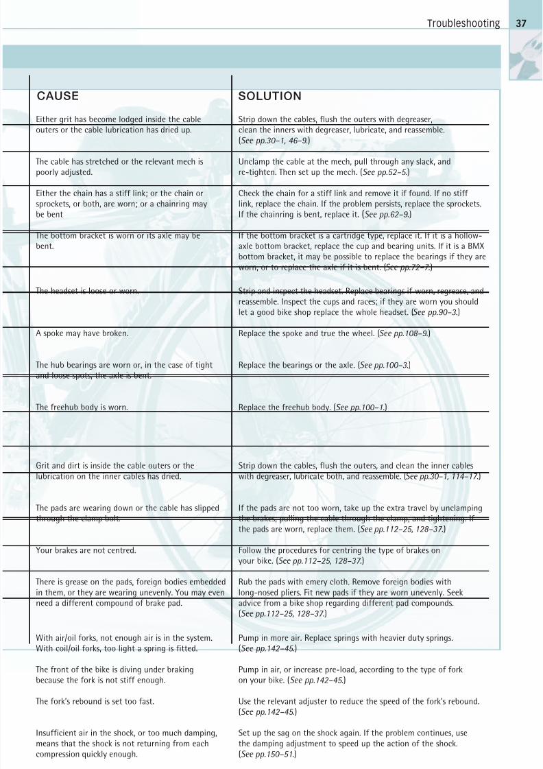
CAUSE SOLUTION
Either grit has become lodged inside the cableouters or the cable lubrication has dried up.
The cable has stretched or the relevant mech ispoorly adjusted.
Either the chain has a stiff link; or the chain orsprockets, or both, are worn; or a chainring maybe bent
The bottom bracket is worn or its axle may bebent.
Strip down the cables, flush the outers with degreaser,clean the inners with degreaser, lubricate, and reassemble.(See pp.30–1, 46–9 .)
Unclamp the cable at the mech, pull through any slack, andre-tighten. Then set up the mech. (See pp.52–5 .)
Check the chain for a stiff link and remove it if found. If no stiff link, replace the chain. If the problem persists, replace the sprockets.If the chainring is bent, replace it. (See pp.62–9 .)
If the bottom bracket is a cartridge type, replace it. If it is a hollow-axle bottom bracket, replace the cup and bearing units. If it is a BMXbottom bracket, it may be possible to replace the bearings if they are
worn, or to replace the axle if it is bent. (See pp.72–7 .)
The headset is loose or worn.
A spoke may have broken.
The hub bearings are worn or, in the case of tightand loose spots, the axle is bent.
The freehub body is worn.
Strip and inspect the headset. Replace bearings if worn, regrease, andreassemble. Inspect the cups and races; if they are worn you shouldlet a good bike shop replace the whole headset. (See pp.90–3 .)
Replace the spoke and true the wheel. (See pp.108–9 .)
Replace the bearings or the axle. (See pp.100–3 .)
Replace the freehub body. (See pp.100–1.)
Grit and dirt is inside the cable outers or thelubrication on the inner cables has dried.
The pads are wearing down or the cable has slippedthrough the clamp bolt.
Your brakes are not centred.
There is grease on the pads, foreign bodies embeddedin them, or they are wearing unevenly. You may evenneed a different compound of brake pad.
Strip down the cables, flush the outers, and clean the inner cableswith degreaser, lubricate both, and reassemble. (See pp.30–1, 114–17 .)
If the pads are not too worn, take up the extra travel by unclampingthe brakes, pulling the cable through the clamp, and tightening. If the pads are worn, replace them. (See pp.112–25, 128–37 .)
Follow the procedures for centring the type of brakes onyour bike. (See pp.112–25, 128–37 .)
Rub the pads with emery cloth. Remove foreign bodies withlong-nosed pliers. Fit new pads if they are worn unevenly. Seekadvice from a bike shop regarding different pad compounds.(See pp.112–25, 128–37 .)
With air/oil forks, not enough air is in the system.With coil/oil forks, too light a spring is fitted.
The front of the bike is diving under brakingbecause the fork is not stiff enough.
The fork’s rebound is set too fast.
Insufficient air in the shock, or too much damping,means that the shock is not returning from eachcompression quickly enough.
Pump in more air. Replace springs with heavier duty springs.(See pp.142–45 .)
Pump in air, or increase pre-load, according to the type of forkon your bike. (See pp.142–45 .)
Use the relevant adjuster to reduce the speed of the fork’s rebound.(See pp.142–45 .)
Set up the sag on the shock again. If the problem continues, usethe damping adjustment to speed up the action of the shock.(See pp.150–51.)
37
8/20/2019 Bike Repair Manual.downarchive
http://slidepdf.com/reader/full/bike-repair-manualdownarchive 38/160
CARING FOR YOUR BIKE
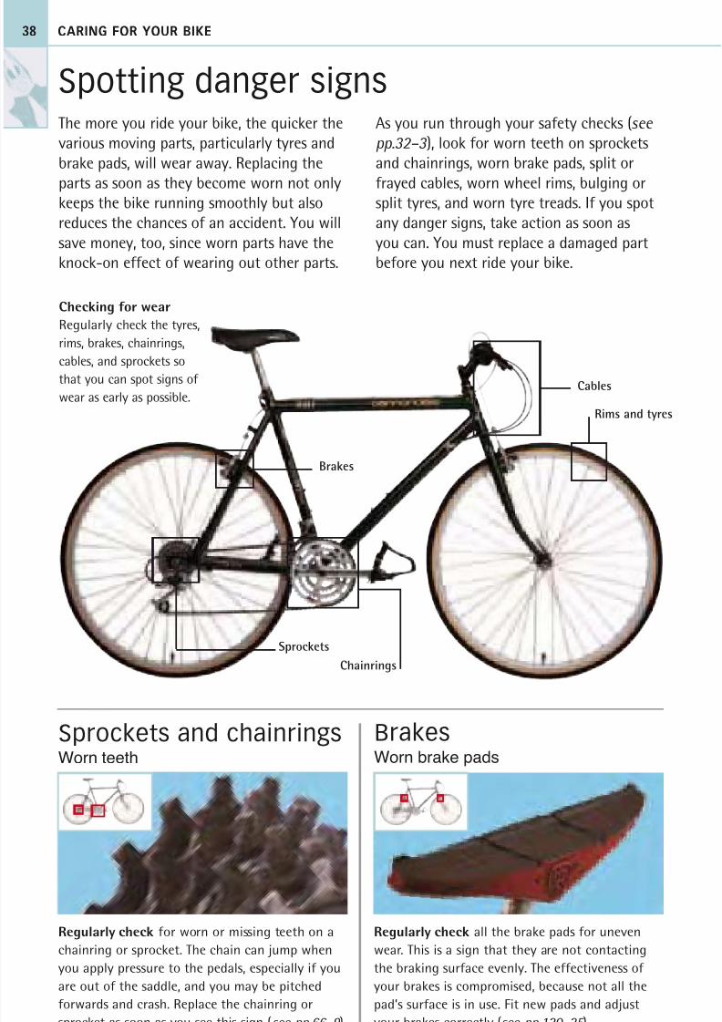
Regularly check all the brake pads for uneven
wear. This is a sign that they are not contacting
the braking surface evenly. The effectiveness of
your brakes is compromised, because not all the
pad’s surface is in use. Fit new pads and adjust
your brakes correctly (see pp.120–25 ).
Regularly check for worn or missing teeth on a
chainring or sprocket. The chain can jump when
you apply pressure to the pedals, especially if you
are out of the saddle, and you may be pitched
forwards and crash. Replace the chainring or
sprocket as soon as you see this sign (see pp.66–9 ).
38
The more you ride your bike, the quicker thevarious moving parts, particularly tyres andbrake pads, will wear away. Replacing the
parts as soon as they become worn not onlykeeps the bike running smoothly but alsoreduces the chances of an accident. You willsave money, too, since worn parts have theknock-on effect of wearing out other parts.
As you run through your safety checks (see pp.32–3 ), look for worn teeth on sprocketsand chainrings, worn brake pads, split or
frayed cables, worn wheel rims, bulging orsplit tyres, and worn tyre treads. If you spotany danger signs, take action as soon asyou can. You must replace a damaged partbefore you next ride your bike.
Spotting danger signs
Sprockets and chainrings Brakes
Cables
Rims and tyres
Sprockets
Chainrings
Brakes
Worn teeth Worn brake pads
Checking for wear
Regularly check the tyres,
rims, brakes, chainrings,
cables, and sprockets sothat you can spot signs of
wear as early as possible.
8/20/2019 Bike Repair Manual.downarchive
http://slidepdf.com/reader/full/bike-repair-manualdownarchive 39/160
Spotting danger signs
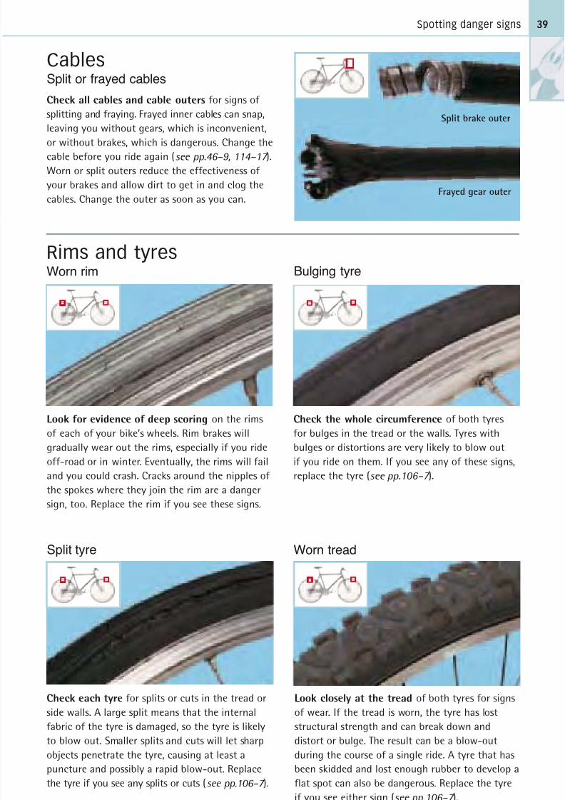
Check the whole circumference of both tyresfor bulges in the tread or the walls. Tyres with
bulges or distortions are very likely to blow out
if you ride on them. If you see any of these signs,
replace the tyre (see pp.106–7 ).
Check all cables and cable outers for signs of
splitting and fraying. Frayed inner cables can snap,
leaving you without gears, which is inconvenient,
or without brakes, which is dangerous. Change thecable before you ride again (see pp.46–9, 114–17 ).
Worn or split outers reduce the effectiveness of
your brakes and allow dirt to get in and clog the
cables. Change the outer as soon as you can.
Look for evidence of deep scoring on the rimsof each of your bike’s wheels. Rim brakes will
gradually wear out the rims, especially if you ride
off-road or in winter. Eventually, the rims will fail
and you could crash. Cracks around the nipples of
the spokes where they join the rim are a danger
sign, too. Replace the rim if you see these signs.
Check each tyre for splits or cuts in the tread orside walls. A large split means that the internal
fabric of the tyre is damaged, so the tyre is likely
to blow out. Smaller splits and cuts will let sharp
objects penetrate the tyre, causing at least a
puncture and possibly a rapid blow-out. Replace
the tyre if you see any splits or cuts (see pp.106–7 ).
39
Cables
Look closely at the tread of both tyres for signsof wear. If the tread is worn, the tyre has lost
structural strength and can break down and
distort or bulge. The result can be a blow-out
during the course of a single ride. A tyre that has
been skidded and lost enough rubber to develop a
flat spot can also be dangerous. Replace the tyre
if you see either sign (see pp.106–7 ).
Rims and tyres
Split brake outer
Frayed gear outer
Split tyre Worn tread
Worn rim
Split or frayed cables
Bulging tyre
8/20/2019 Bike Repair Manual.downarchive
http://slidepdf.com/reader/full/bike-repair-manualdownarchive 40/160
CARING FOR YOUR BIKE
Preparing for wet weather
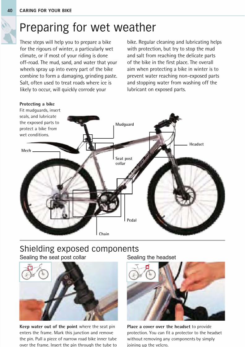
Keep water out of the point where the seat pin
enters the frame. Mark this junction and remove
the pin. Pull a piece of narrow road bike inner tube
over the frame. Insert the pin through the tube to
the mark and tie-wrap the tube to secure it.
40
These steps will help you to prepare a bike
for the rigours of winter, a particularly wet
climate, or if most of your riding is done
off-road. The mud, sand, and water that yourwheels spray up into every part of the bike
combine to form a damaging, grinding paste.
Salt, often used to treat roads where ice is
likely to occur, will quickly corrode your
bike. Regular cleaning and lubricating helps
with protection, but try to stop the mud
and salt from reaching the delicate parts
of the bike in the first place. The overallaim when protecting a bike in winter is to
prevent water reaching non-exposed parts
and stopping water from washing off the
lubricant on exposed parts.
Place a cover over the headset to provide
protection. You can fit a protector to the headset
without removing any components by simply
joining up the velcro.
Shielding exposed componentsSealing the seat post collar Sealing the headset
Mech
Pedal
Headset
Seat postcollar
Mudguard
Chain
Protecting a bike
Fit mudguards, insert
seals, and lubricate
the exposed parts to
protect a bike from
wet conditions.
8/20/2019 Bike Repair Manual.downarchive
http://slidepdf.com/reader/full/bike-repair-manualdownarchive 41/160
Preparing for wet weather
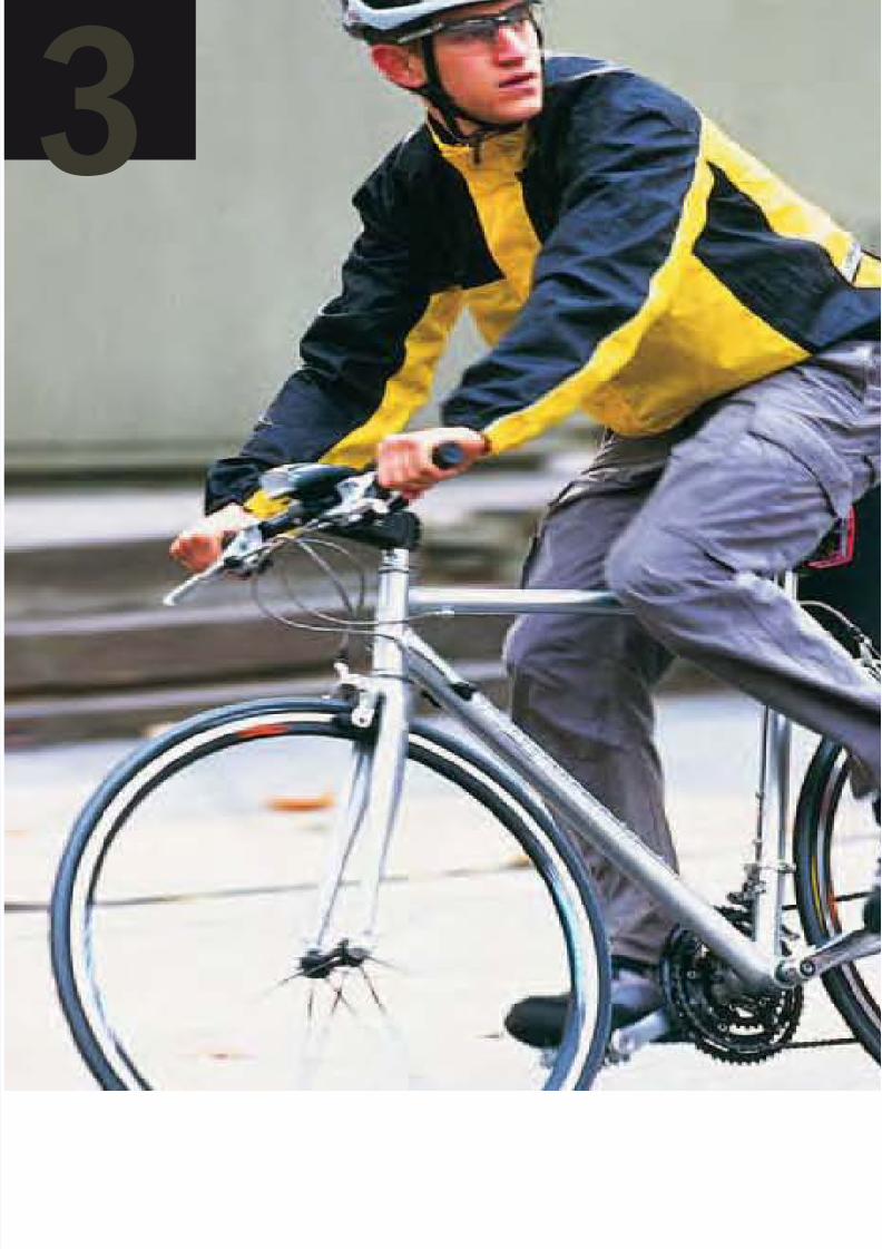
Lubricate and clean your chain as often as
you do in summer and after every wet ride.
Apply the same light lubricant that you use in
the summer and then apply a heavier oil, which
will not wash off as easily. Only coat the rollers
and insides of each link with heavier oil becauseit attracts more dirt.
41
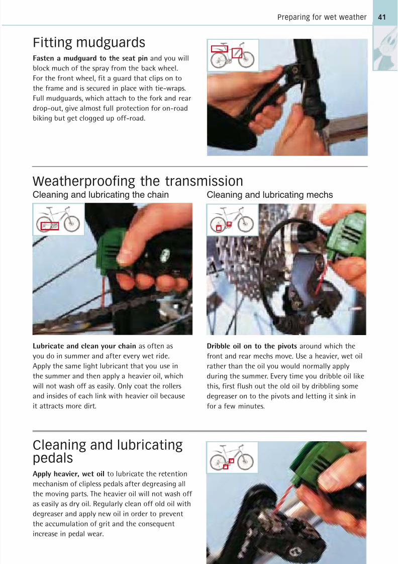
Fitting mudguardsFasten a mudguard to the seat pin and you will
block much of the spray from the back wheel.
For the front wheel, fit a guard that clips on to
the frame and is secured in place with tie-wraps.
Full mudguards, which attach to the fork and reardrop-out, give almost full protection for on-road
biking but get clogged up off-road.
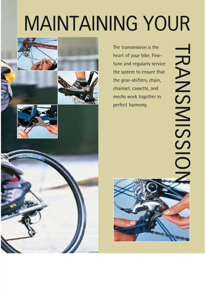
Dribble oil on to the pivots around which the
front and rear mechs move. Use a heavier, wet oil
rather than the oil you would normally apply
during the summer. Every time you dribble oil like
this, first flush out the old oil by dribbling some
degreaser on to the pivots and letting it sink infor a few minutes.
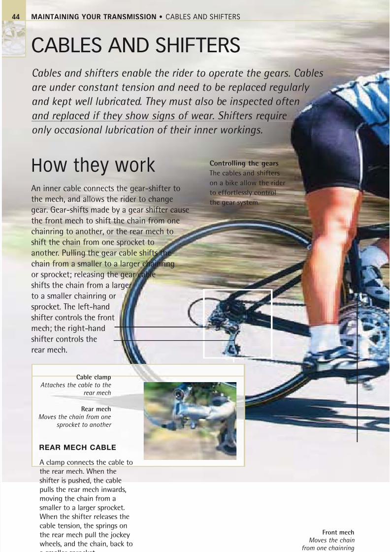
Apply heavier, wet oil to lubricate the retention
mechanism of clipless pedals after degreasing all
the moving parts. The heavier oil will not wash off as easily as dry oil. Regularly clean off old oil with
degreaser and apply new oil in order to prevent
the accumulation of grit and the consequent
increase in pedal wear.
Cleaning and lubricating mechs
Cleaning and lubricatingpedals
Weatherproofing the transmission
Cleaning and lubricating the chain
8/20/2019 Bike Repair Manual.downarchive
http://slidepdf.com/reader/full/bike-repair-manualdownarchive 42/160
3
8/20/2019 Bike Repair Manual.downarchive
http://slidepdf.com/reader/full/bike-repair-manualdownarchive 43/160
MAINTAINING YOURThe transmission is the
heart of your bike. Fine-
tune and regularly service
the system to ensure that
the gear-shifters, chain,
chainset, cassette, and
mechs work together in
perfect harmony.
T R A N
S MI S
S I O N
8/20/2019 Bike Repair Manual.downarchive
http://slidepdf.com/reader/full/bike-repair-manualdownarchive 44/160
MAINTAINING YOUR TRANSMISSION • CABLES AND SHIFTERS
CABLES AND SHIFTERS
Cables and shifters enable the rider to operate the gears. Cables
are under constant tension and need to be replaced regularly
and kept well lubricated. They must also be inspected often
and replaced if they show signs of wear. Shifters require
only occasional lubrication of their inner workings.
How they workAn inner cable connects the gear-shifter to
the mech, and allows the rider to change
gear. Gear-shifts made by a gear shifter cause
the front mech to shift the chain from one
chainring to another, or the rear mech to
shift the chain from one sprocket to
another. Pulling the gear cable shifts the
chain from a smaller to a larger chainring
or sprocket; releasing the gear cable
shifts the chain from a larger
to a smaller chainring or
sprocket. The left-hand
shifter controls the front
mech; the right-hand
shifter controls the
rear mech.
Controlling the gears
The cables and shifters
on a bike allow the rider
to effortlessly controlthe gear system.
A clamp connects the cable to
the rear mech. When the
shifter is pushed, the cablepulls the rear mech inwards,
moving the chain from a
smaller to a larger sprocket.
When the shifter releases the
cable tension, the springs on
the rear mech pull the jockey
wheels, and the chain, back to
a smaller sprocket.
REAR MECH CABLE
Cable clamp
Attaches the cable to the rear mech
Rear mechMoves the chain from one
sprocket to another
44
Front mechMoves the chain
from one chainring to another
8/20/2019 Bike Repair Manual.downarchive
http://slidepdf.com/reader/full/bike-repair-manualdownarchive 45/160
How they work
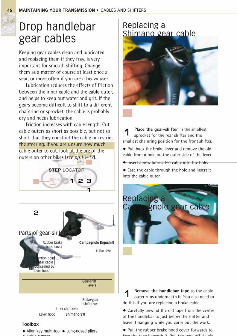
Gear-shifters are often combined
with the brake levers on the
handlebar. On this Shimano gear-
shifter, the brake lever also acts
as a shift lever. When the rider
pushes the brake lever inwards
with the fingers, the control
cable attached to it is pulled and
a ratchet mechanism is lifted.
A click of this mechanism equals
one shift of the front or rear
mech, which moves the chainacross the chainring or sprockets.
The ratchet mechanism then
holds the cable in its new
position. When the rider pushes
the inner shift lever inwards,
the ratchet mechanism’s hold
is released and so the shifter’s
pull on the cable ceases.
COMBINED BRAKE LEVER/GEAR SHIFTER ANATOMY
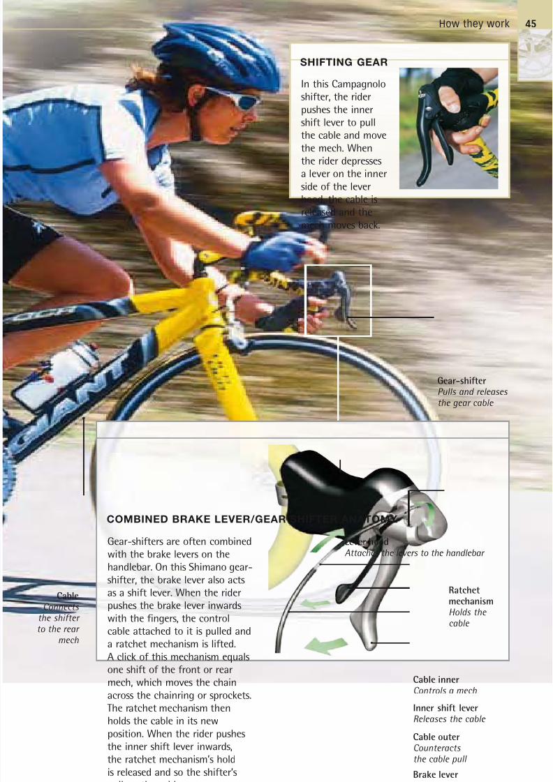
Gear-shifter
Pulls and releasesthe gear cable
Ratchet
mechanism
Holds the cable
Brake lever
Pulls the cable
Inner shift lever
Releases the cable
Cable outer
Counteracts the cable pull
Cable inner
Controls a mech
Lever hood
Attaches the levers to the handlebar
Cable
Connects the shifter to the rear
mech
45
SHIFTING GEAR
In this Campagnolo
shifter, the rider
pushes the inner
shift lever to pull
the cable and movethe mech. When
the rider depresses
a lever on the inner
side of the lever
hood, the cable is
released and the
mech moves back.
8/20/2019 Bike Repair Manual.downarchive
http://slidepdf.com/reader/full/bike-repair-manualdownarchive 46/160
STEP LOCATOR
1
2
MAINTAINING YOUR TRANSMISSION • CABLES AND SHIFTERS46
Drop handlebargear cablesKeeping gear cables clean and lubricated,
and replacing them if they fray, is veryimportant for smooth shifting. Changethem as a matter of course at least once ayear, or more often if you are a heavy user.
Lubrication reduces the effects of frictionbetween the inner cable and the cable outer,and helps to keep out water and grit. If thegears become difficult to shift to a differentchainring or sprocket, the cable is probably
dry and needs lubrication.Friction increases with cable length. Cut
cable outers as short as possible, but not soshort that they constrict the cable or restrictthe steering. If you are unsure how muchcable outer to cut, look at the arc of theouters on other bikes (see pp.10–17 ).
Replacing aCampagnolo gear cable
Replacing aShimano gear cable
Remove the handlebar tape as the cable
outer runs underneath it. You also need to
do this if you are replacing a brake cable.
• Carefully unwind the old tape from the centre
of the handlebar to just below the shifter and
leave it hanging while you carry out the work.
• Pull the rubber brake hood cover forwards to
free the tape beneath it. Pull the tape off slowly.
1
Place the gear-shifter in the smallest
sprocket for the rear shifter and the
smallest chainring position for the front shifter.
• Pull back the brake lever and remove the old
cable from a hole on the outer side of the lever.
• Insert a new lubricated cable into the hole.
• Ease the cable through the hole and insert it
into the cable outer.
1
Toolbox
Allen key multi-tool Long-nosed pliers
Cable cutters
Parts of gear-shift unitsCampagnolo Ergoshift
Shimano STI
Gear-shiftlevers
Brake/gear-shift lever
Inner shift lever
Insertion pointof gear cable(concealed bylever hood)
1 2 3
Lever hood
Rubber brakehood cover
Brake lever
8/20/2019 Bike Repair Manual.downarchive
http://slidepdf.com/reader/full/bike-repair-manualdownarchive 47/160
Drop handlebar gear cables 47
Put the rear shifter in the smallest sprocket
and the front shifter in the smallest chainring.
Remove the old cable from under the hood cover.
• Grease the new cable and push it through the
hole under the hood cover.
2
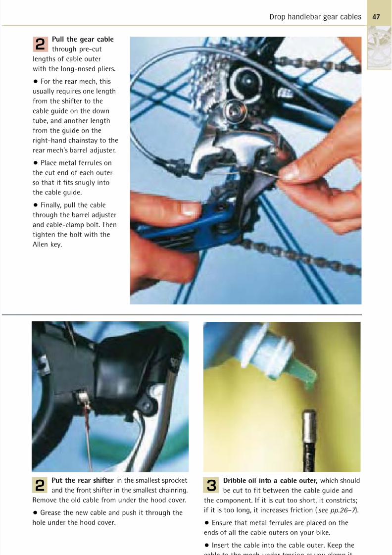
Pull the gear cable
through pre-cut
lengths of cable outer
with the long-nosed pliers.
• For the rear mech, this
usually requires one length
from the shifter to the
cable guide on the down
tube, and another length
from the guide on the
right-hand chainstay to the
rear mech’s barrel adjuster.
• Place metal ferrules on
the cut end of each outer
so that it fits snugly into
the cable guide.• Finally, pull the cable
through the barrel adjuster
and cable-clamp bolt. Then
tighten the bolt with the
Allen key.
2
Dribble oil into a cable outer, which should
be cut to fit between the cable guide and
the component. If it is cut too short, it constricts;
if it is too long, it increases friction (see pp.26–7 ).
• Ensure that metal ferrules are placed on the
ends of all the cable outers on your bike.
• Insert the cable into the cable outer. Keep the
cable to the mech under tension as you clamp it.
3
8/20/2019 Bike Repair Manual.downarchive
http://slidepdf.com/reader/full/bike-repair-manualdownarchive 48/160
STEP LOCATOR
4
MAINTAINING YOUR TRANSMISSION • CABLES AND SHIFTERS48
Straight handlebargear cablesLooking after and replacing the gear cables
on a mountain bike is very similar to a roadbike. However, mountain bikes are often
subjected to harsher conditions than road
bikes, as they are often ridden through dirt
and mud, so the cables must be replaced
and lubricated more regularly.
Take special care if your mountain bike
has cable disc brakes because they have
longer lengths of cable outer and the cables
require lubricating more often.
Replacing aRapidfire gear cable
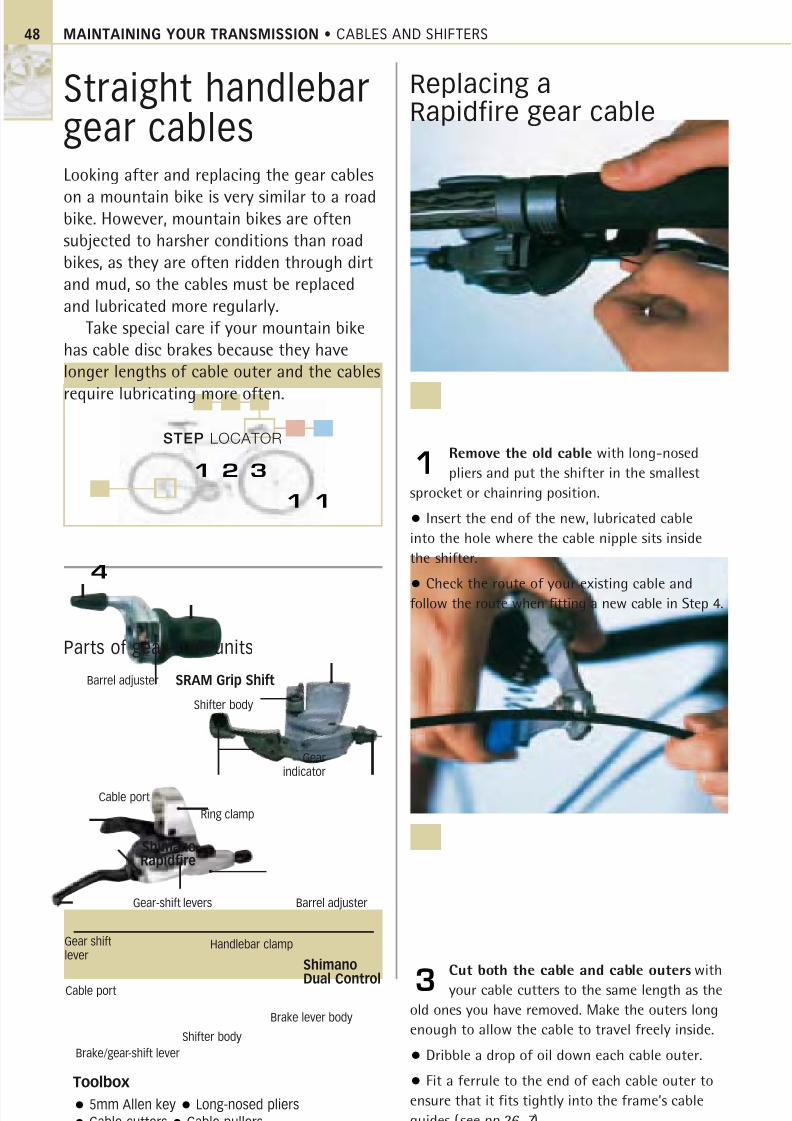
Remove the old cable with long-nosed
pliers and put the shifter in the smallest
sprocket or chainring position.
• Insert the end of the new, lubricated cable
into the hole where the cable nipple sits inside
the shifter.
• Check the route of your existing cable andfollow the route when fitting a new cable in Step 4.
1
Cut both the cable and cable outers with
your cable cutters to the same length as the
old ones you have removed. Make the outers long
enough to allow the cable to travel freely inside.
• Dribble a drop of oil down each cable outer.
• Fit a ferrule to the end of each cable outer to
ensure that it fits tightly into the frame’s cable
guides (see pp.26–7 ).
3
Toolbox
5mm Allen key Long-nosed pliers
Cable cutters Cable pullers
Parts of gear-shift units
Gear-shift levers
Handlebar clamp
Brake lever body
Shifter body
1 2 3
1 1
Gearindicator
Ring clamp
Barrel adjuster
Barrel adjuster
Shifter body
ShimanoRapidfire
Shimano
Dual Control
SRAM Grip Shift
Cable port
Brake/gear-shift lever
Gear shiftlever
Cable port
8/20/2019 Bike Repair Manual.downarchive
http://slidepdf.com/reader/full/bike-repair-manualdownarchive 49/160
Straight handlebar gear cables 49
Replacing aGrip Shift gear cable
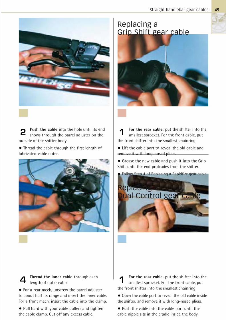
Push the cable into the hole until its end
shows through the barrel adjuster on the
outside of the shifter body.
• Thread the cable through the first length of
lubricated cable outer.
2
Replacing aDual Control gear cable
Thread the inner cable through each
length of outer cable.
• For a rear mech, unscrew the barrel adjuster
to about half its range and insert the inner cable.
For a front mech, insert the cable into the clamp.
• Pull hard with your cable pullers and tighten
the cable clamp. Cut off any excess cable.
4
For the rear cable, put the shifter into the
smallest sprocket. For the front cable, put
the front shifter into the smallest chainring.
• Open the cable port to reveal the old cable inside
the shifter, and remove it with long-nosed pliers.
• Push the cable into the cable port until the
cable nipple sits in the cradle inside the body.
• Follow Step 4 of Replacing a Rapidfire gear cable.
1
For the rear cable, put the shifter into the
smallest sprocket. For the front cable, put
the front shifter into the smallest chainring.
• Lift the cable port to reveal the old cable and
remove it with long-nosed pliers.
• Grease the new cable and push it into the Grip
Shift until the end protrudes from the shifter.• Follow Step 4 of Replacing a Rapidfire gear cable.
1

8/20/2019 Bike Repair Manual.downarchive
http://slidepdf.com/reader/full/bike-repair-manualdownarchive 50/160
MAINTAINING YOUR TRANSMISSION • FRONT AND REAR MECHS
FRONT AND REAR MECHS
The two mechs move the chain smoothly between the sprockets and
chainrings, but only if the travel of the mechs is set up correctly. The
mech pivots and jockey wheels must be checked for wear and lubricated.
The front mech must be properly aligned with the chainrings.
How they workThe front and rear mechs change the gears on a bike. To
change up a gear, the shifter is used to pull on the cable,
which causes the front mech to push the chain from asmaller to a larger chainring or the rear mech to push
the chain from a smaller to a larger sprocket. To change
down a gear, the cable is released, causing the springs in
both mechs to move the chain to a smaller chainring or
sprocket. Each mech moves around a pivot point. High
and low adjusting screws ensure that the mechs do not
push the chain beyond the largest chainring or sprocket,
or pull it beyond the smallest. This range is called the
mech’s travel. Once its travel is set up, and provided thecable tension is sufficient, the mech will make a single,
clean gear-shift for every click of the shifter.
Working with the shifters
The front and rear mechs work
in harmony with the shifters
to provide easy, quick, and
accurate gear-shifts whenever
the rider needs them.
To change gear, two jockey wheels transfer the chain on to a
different sprocket. They move in the same plane as the chain
and are spring-loaded to preserve the tension in the chain.
Two mech plates enable the jockey wheels to change gear
upwards, while the plate spring enables the jockey wheelsto change gear downwards.
REAR MECH ANATOMY
CablePushes and pulls therear mech
Rear mechTransfers the
chain fromone sprocket to another
Jockey wheel springPreserves the tension in the chain
Jockey wheelPulls and pushes
the chain
Jockey wheel cageHolds the jockey wheels
Cable clampAttaches the cable to the mech plates
CablePulls the mech plates
Mech plateTransfers cable pull to the
jockey wheels
Plate springPulls the mech back as cable is released
High and lowadjustersLimit the travel of the mech
50
8/20/2019 Bike Repair Manual.downarchive
http://slidepdf.com/reader/full/bike-repair-manualdownarchive 51/160
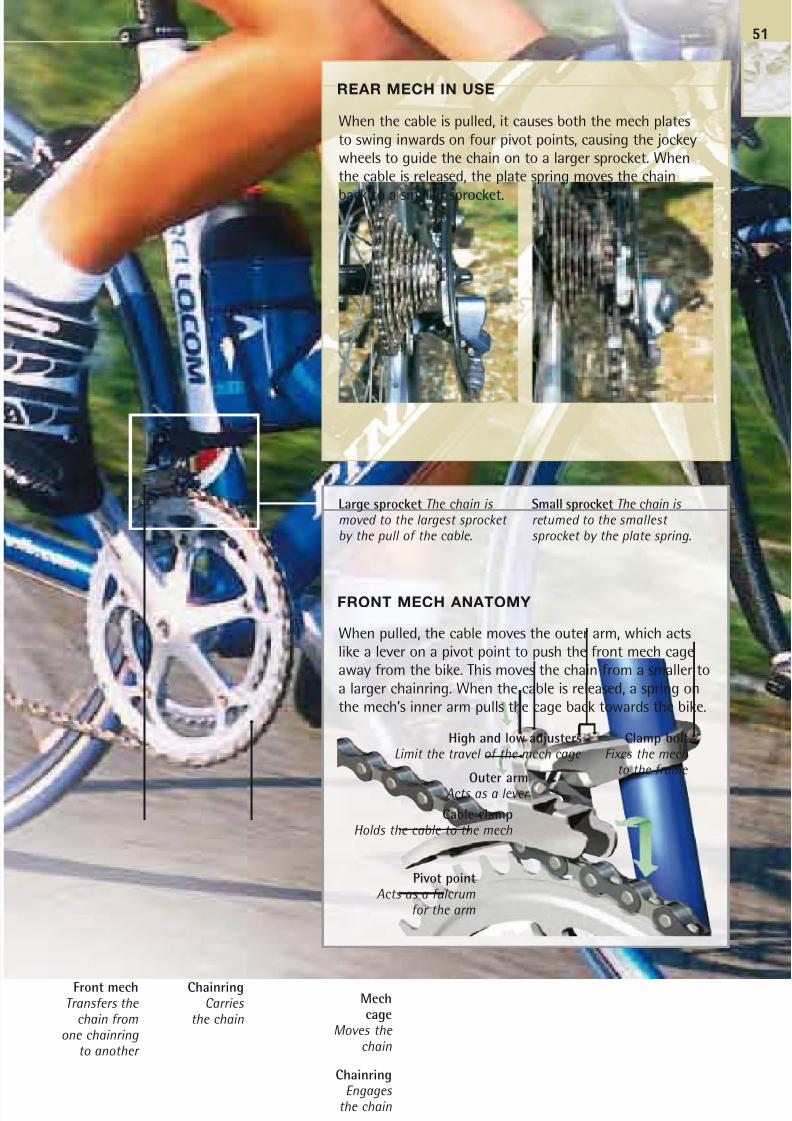
When pulled, the cable moves the outer arm, which acts
like a lever on a pivot point to push the front mech cage
away from the bike. This moves the chain from a smaller to
a larger chainring. When the cable is released, a spring on
the mech’s inner arm pulls the cage back towards the bike.
FRONT MECH ANATOMY
REAR MECH IN USE
When the cable is pulled, it causes both the mech plates
to swing inwards on four pivot points, causing the jockey
wheels to guide the chain on to a larger sprocket. When
the cable is released, the plate spring moves the chain
back to a smaller sprocket.
Front mechTransfers the
chain fromone chainring
to another
ChainringCarries
the chain
Small sprocket The chain is returned to the smallestsprocket by the plate spring.
Large sprocket The chain is moved to the largest sprocket by the pull of the cable.
51
Mechcage
Moves the
chain
Pivot pointActs as a fulcrum
for the arm
Cable clampHolds the cable to the mech
Clamp boltFixes the mech
to the frame
High and low adjustersLimit the travel of the mech cage
Outer armActs as a lever
ChainringEngages
the chain
8/20/2019 Bike Repair Manual.downarchive
http://slidepdf.com/reader/full/bike-repair-manualdownarchive 52/160
STEP LOCATOR
MAINTAINING YOUR TRANSMISSION • FRONT AND REAR MECHS52
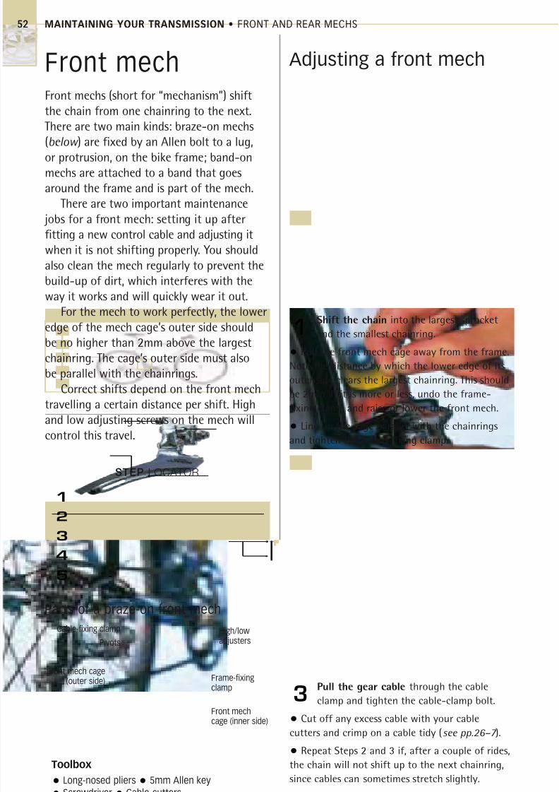
Front mechFront mechs (short for “mechanism”) shiftthe chain from one chainring to the next.There are two main kinds: braze-on mechs
(below ) are fixed by an Allen bolt to a lug,or protrusion, on the bike frame; band-onmechs are attached to a band that goesaround the frame and is part of the mech.
There are two important maintenance jobs for a front mech: setting it up afterfitting a new control cable and adjusting itwhen it is not shifting properly. You shouldalso clean the mech regularly to prevent the
build-up of dirt, which interferes with theway it works and will quickly wear it out.
For the mech to work perfectly, the loweredge of the mech cage’s outer side shouldbe no higher than 2mm above the largestchainring. The cage’s outer side must alsobe parallel with the chainrings.
Correct shifts depend on the front mechtravelling a certain distance per shift. High
and low adjusting screws on the mech willcontrol this travel.
Adjusting a front mech
Shift the chain into the largest sprocket
and the smallest chainring.
• Pull the front mech cage away from the frame.
Note the distance by which the lower edge of its
outer side clears the largest chainring. This should
be 2mm. If it is more or less, undo the frame-
fixing clamp and raise or lower the front mech.
• Line up the cage parallel with the chainrings
and tighten the frame-fixing clamp.
1
Pull the gear cable through the cable
clamp and tighten the cable-clamp bolt.
• Cut off any excess cable with your cable
cutters and crimp on a cable tidy (see pp.26–7 ).
• Repeat Steps 2 and 3 if, after a couple of rides,
the chain will not shift up to the next chainring,
since cables can sometimes stretch slightly.
3
Toolbox
Long-nosed pliers 5mm Allen key
Screwdriver Cable cutters
Parts of a braze-on front mech
High/lowadjusters
Front mechcage (inner side)
Front mech cage(outer side)
Cable-fixing clamp
1
2
3
4
5
Frame-fixingclamp
Pivots
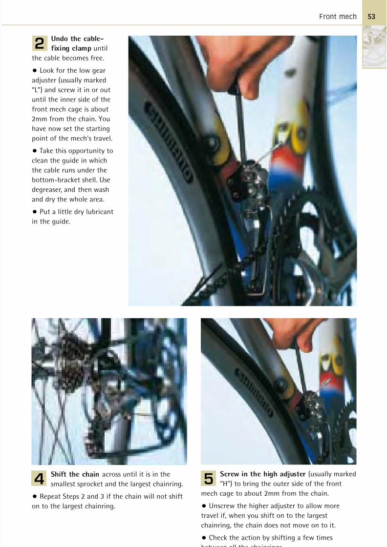
8/20/2019 Bike Repair Manual.downarchive
http://slidepdf.com/reader/full/bike-repair-manualdownarchive 53/160
Front mech 53
Undo the cable-
fixing clamp until
the cable becomes free.
• Look for the low gear
adjuster (usually marked
“L”) and screw it in or out
until the inner side of the
front mech cage is about
2mm from the chain. You
have now set the starting
point of the mech’s travel.
• Take this opportunity to
clean the guide in which
the cable runs under the
bottom-bracket shell. Use
degreaser, and then washand dry the whole area.
• Put a little dry lubricant
in the guide.
2
Screw in the high adjuster (usually marked
“H”) to bring the outer side of the front
mech cage to about 2mm from the chain.
• Unscrew the higher adjuster to allow more
travel if, when you shift on to the largest
chainring, the chain does not move on to it.
• Check the action by shifting a few times
between all the chainrings.
5Shift the chain across until it is in the
smallest sprocket and the largest chainring.
• Repeat Steps 2 and 3 if the chain will not shift
on to the largest chainring.
4
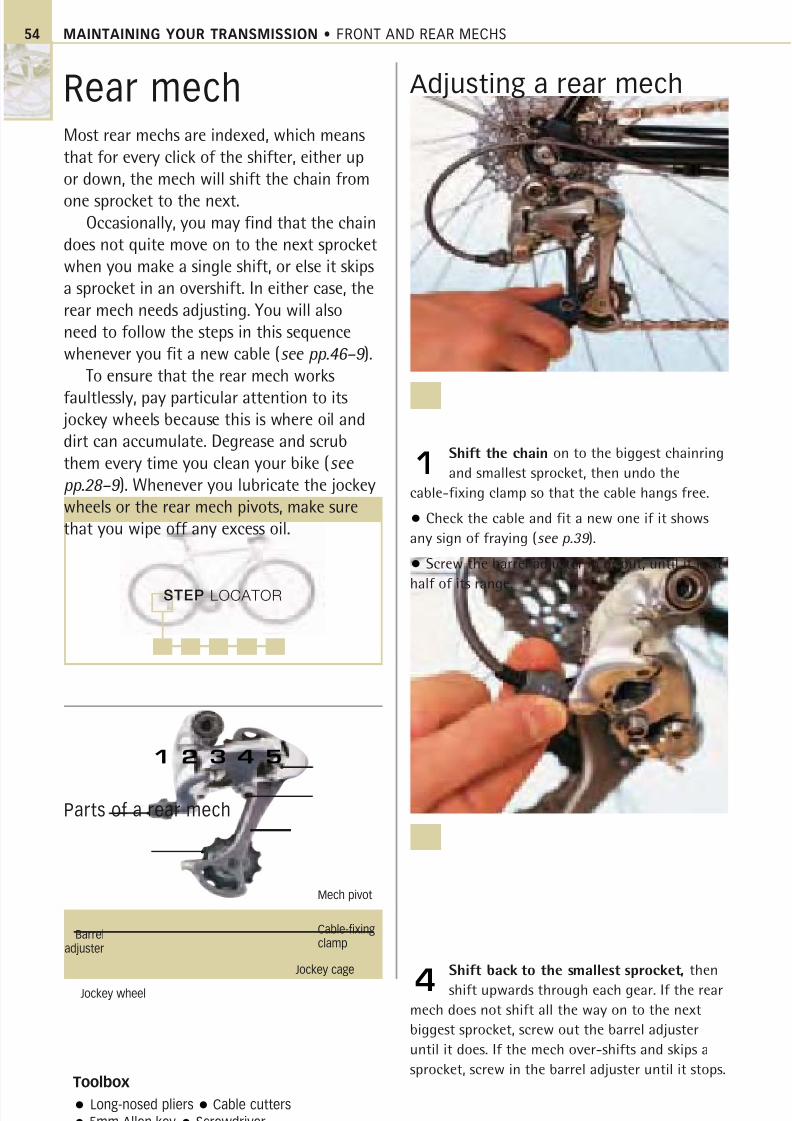
8/20/2019 Bike Repair Manual.downarchive
http://slidepdf.com/reader/full/bike-repair-manualdownarchive 54/160
STEP LOCATOR
MAINTAINING YOUR TRANSMISSION • FRONT AND REAR MECHS
Rear mechMost rear mechs are indexed, which meansthat for every click of the shifter, either upor down, the mech will shift the chain from
one sprocket to the next.Occasionally, you may find that the chain
does not quite move on to the next sprocketwhen you make a single shift, or else it skipsa sprocket in an overshift. In either case, therear mech needs adjusting. You will alsoneed to follow the steps in this sequencewhenever you fit a new cable (see pp.46–9 ).
To ensure that the rear mech works
faultlessly, pay particular attention to its jockey wheels because this is where oil anddirt can accumulate. Degrease and scrubthem every time you clean your bike (see
pp.28–9 ). Whenever you lubricate the jockeywheels or the rear mech pivots, make surethat you wipe off any excess oil.
Adjusting a rear mech
Shift the chain on to the biggest chainring
and smallest sprocket, then undo the
cable-fixing clamp so that the cable hangs free.
• Check the cable and fit a new one if it shows
any sign of fraying (see p.39 ).
• Screw the barrel adjuster in or out, until it is at
half of its range.
1
Shift back to the smallest sprocket, then
shift upwards through each gear. If the rear
mech does not shift all the way on to the next
biggest sprocket, screw out the barrel adjuster
until it does. If the mech over-shifts and skips a
sprocket, screw in the barrel adjuster until it stops.
4
Toolbox
Long-nosed pliers Cable cutters
5mm Allen key Screwdriver
Parts of a rear mech
Jockey wheel
Barreladjuster
Mech pivot
Jockey cage
Cable-fixingclamp
1 2 3 4 5
54
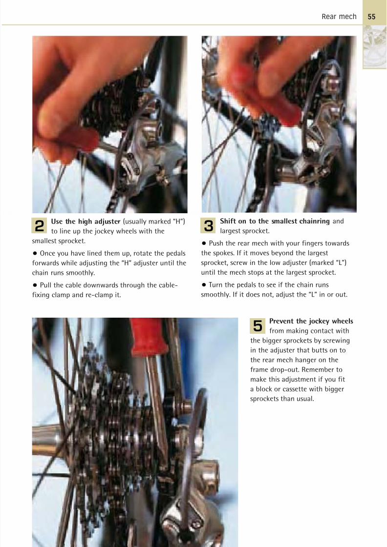
8/20/2019 Bike Repair Manual.downarchive
http://slidepdf.com/reader/full/bike-repair-manualdownarchive 55/160
Rear mech
Use the high adjuster (usually marked “H”)
to line up the jockey wheels with the
smallest sprocket.
• Once you have lined them up, rotate the pedals
forwards while adjusting the “H” adjuster until the
chain runs smoothly.
• Pull the cable downwards through the cable-fixing clamp and re-clamp it.
2
Prevent the jockey wheels
from making contact with
the bigger sprockets by screwing
in the adjuster that butts on to
the rear mech hanger on the
frame drop-out. Remember to
make this adjustment if you fit
a block or cassette with bigger
sprockets than usual.
5
Shift on to the smallest chainring and
largest sprocket.
• Push the rear mech with your fingers towards
the spokes. If it moves beyond the largest
sprocket, screw in the low adjuster (marked “L”)
until the mech stops at the largest sprocket.
• Turn the pedals to see if the chain runssmoothly. If it does not, adjust the “L” in or out.
3
55
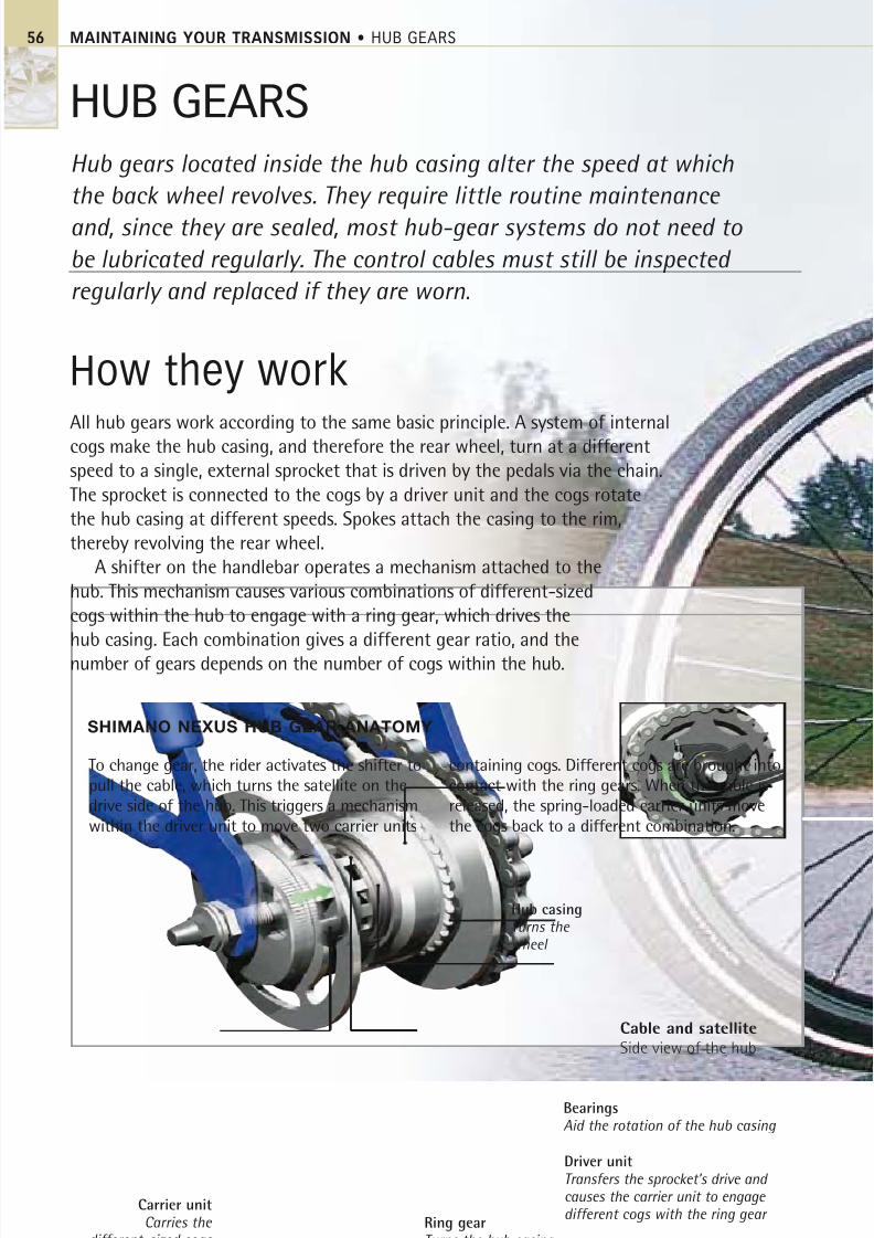
8/20/2019 Bike Repair Manual.downarchive
http://slidepdf.com/reader/full/bike-repair-manualdownarchive 56/160
MAINTAINING YOUR TRANSMISSION • HUB GEARS56
HUB GEARS
Hub gears located inside the hub casing alter the speed at which
the back wheel revolves. They require little routine maintenance
and, since they are sealed, most hub-gear systems do not need to
be lubricated regularly. The control cables must still be inspected
regularly and replaced if they are worn.
How they workAll hub gears work according to the same basic principle. A system of internal
cogs make the hub casing, and therefore the rear wheel, turn at a different
speed to a single, external sprocket that is driven by the pedals via the chain.
The sprocket is connected to the cogs by a driver unit and the cogs rotate
the hub casing at different speeds. Spokes attach the casing to the rim,
thereby revolving the rear wheel.
A shifter on the handlebar operates a mechanism attached to the
hub. This mechanism causes various combinations of different-sized
cogs within the hub to engage with a ring gear, which drives the
hub casing. Each combination gives a different gear ratio, and the
number of gears depends on the number of cogs within the hub.
SHIMANO NEXUS HUB GEAR ANATOMY
Driver unitTransfers the sprocket’s drive and causes the carrier unit to engage different cogs with the ring gear
BearingsAid the rotation of the hub casing
Ring gearTurns the hub casing
Carrier unitCarries the
different-sized cogs
Cable and satellite
Side view of the hub
Hub casingTurns the wheel
To change gear, the rider activates the shifter to
pull the cable, which turns the satellite on the
drive side of the hub. This triggers a mechanism
within the driver unit to move two carrier units
containing cogs. Different cogs are brought into
contact with the ring gears. When the cable is
released, the spring-loaded carrier units move
the cogs back to a different combination.
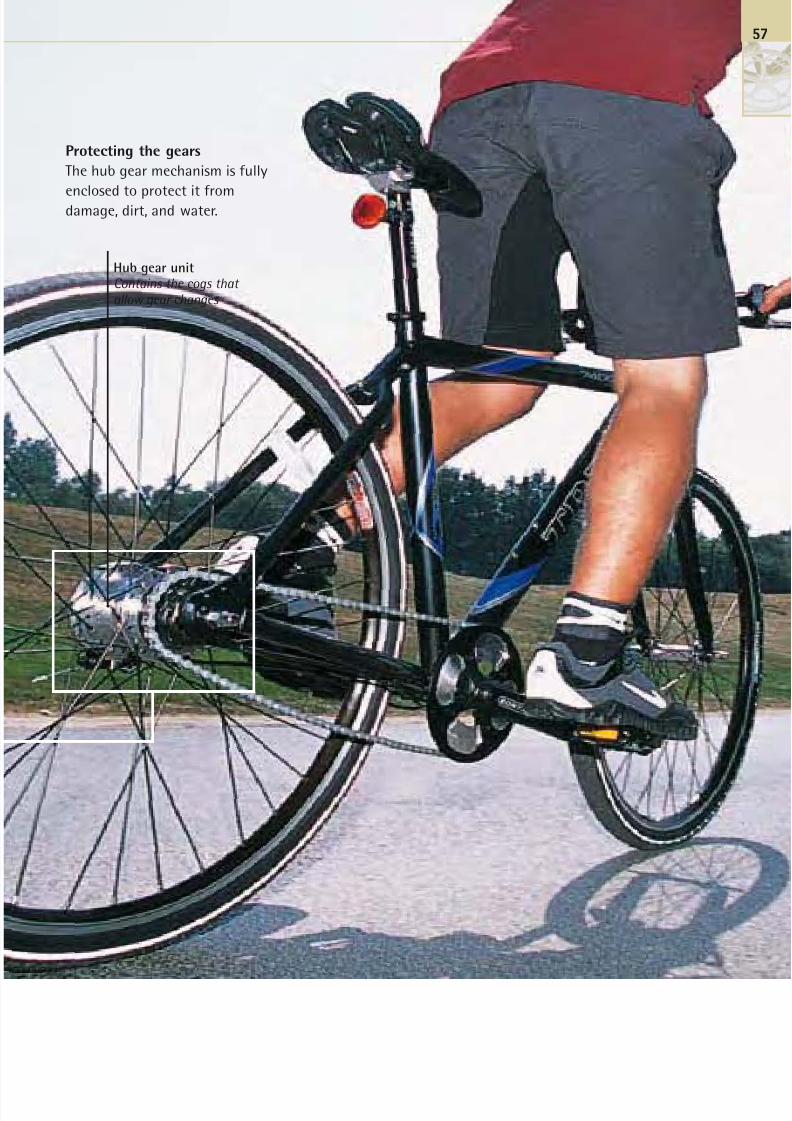
8/20/2019 Bike Repair Manual.downarchive
http://slidepdf.com/reader/full/bike-repair-manualdownarchive 57/160
Protecting the gears
The hub gear mechanism is fully
enclosed to protect it fromdamage, dirt, and water.
Hub gear unitContains the cogs that
allow gear changes
57

8/20/2019 Bike Repair Manual.downarchive
http://slidepdf.com/reader/full/bike-repair-manualdownarchive 58/160
STEP LOCATOR
2
4
MAINTAINING YOUR TRANSMISSION • HUB GEARS
Hub gear IIf the cable to your hub gear breaks or frays,
you will need to replace it. Before making a
start, first identify the hub gear units on
your bike from the manufacturer’s name.This is usually stamped on the hub and the
number of gears is indicated on the shifter.
The hub-gear model illustrated in the
steps of this sequence is the Shimano Nexus
7-speed gear, which is operated by a twist
grip shifter. Alternatively, bikes may be
equipped with SRAM hub gears, as well as
those made by other manufacturers, that
are operated by thumbshifters.Some older bikes have Sturmey Archer
3-speed gears. Although they all work on the
same principle, the methods used to change
a cable are subtly different. Try to find the
manufacturer’s instructions for the gear
fitted to your bike – ask at bike shops or
search the internet.
Replacing ahub-gear cable
Put the shifter into first gear. At this
point, there is no tension on the cable, so
it is the starting point for fitting a new cable.
If the cable is broken, the hub gear will have
automatically returned to first gear, so move
the shifter there to line up the system.
1
Insert the cable through the chainstay
cable guide and make sure that the outer
is well-seated into the guide.
• Pull the cable tight and tighten the clamp
bolt on to it at exactly the distance you measured
from the cable guide in Step 2.
• Now push the clamp bolt back into the place
where it sits on the gear satellite (inset ).
4
Toolbox
Spanners to fit wheel axle nuts and cable-clamp
bolt Flat-bladed screwdriver
Parts of a hub gear
Cable route
Lockring
Position of red dots(underneath)
Seat for cable-retaining bolt Right-hand axle nut
1
3
5
58
Gear satellite
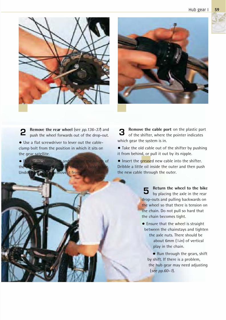
8/20/2019 Bike Repair Manual.downarchive
http://slidepdf.com/reader/full/bike-repair-manualdownarchive 59/160
Hub gear I
Remove the rear wheel (see pp.136–37 ) and
push the wheel forwards out of the drop-out.
• Use a flat screwdriver to lever out the cable-
clamp bolt from the position in which it sits on
the gear satellite.
• Pull on the clamp bolt and measure the length of
the cable between it and the chainstay cable guide.Undo the clamp to remove it from the old cable.
2
Return the wheel to the bike
by placing the axle in the rear
drop-outs and pulling backwards on
the wheel so that there is tension on
the chain. Do not pull so hard that
the chain becomes tight.
• Ensure that the wheel is straightbetween the chainstays and tighten
the axle nuts. There should be
about 6mm (1 ⁄ 4in) of vertical
play in the chain.
• Run through the gears, shift
by shift. If there is a problem,
the hub gear may need adjusting
(see pp.60–1).
5
Remove the cable port on the plastic part
of the shifter, where the pointer indicates
which gear the system is in.
• Take the old cable out of the shifter by pushing
it from behind, or pull it out by its nipple.
• Insert the greased new cable into the shifter.
Dribble a little oil inside the outer and then pushthe new cable through the outer.
3
59
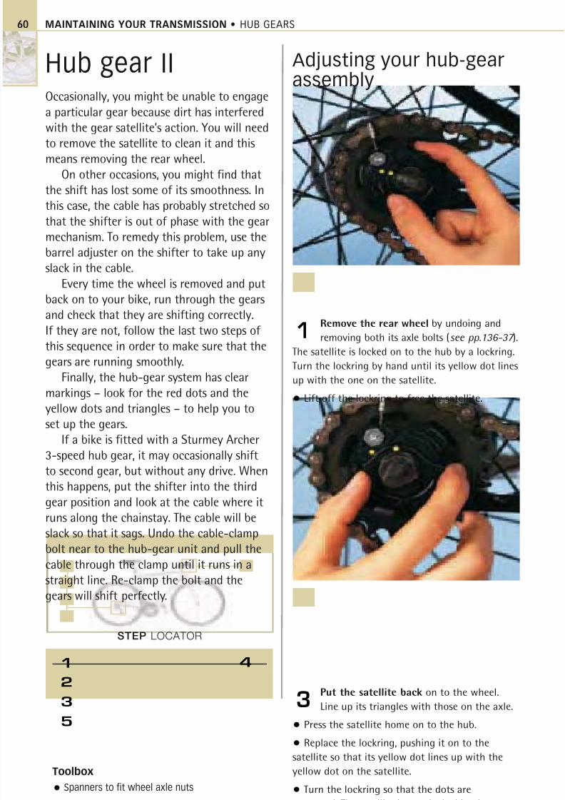
8/20/2019 Bike Repair Manual.downarchive
http://slidepdf.com/reader/full/bike-repair-manualdownarchive 60/160
STEP LOCATOR
2
3
5
MAINTAINING YOUR TRANSMISSION • HUB GEARS
Hub gear IIOccasionally, you might be unable to engage
a particular gear because dirt has interfered
with the gear satellite’s action. You will need
to remove the satellite to clean it and thismeans removing the rear wheel.
On other occasions, you might find that
the shift has lost some of its smoothness. In
this case, the cable has probably stretched so
that the shifter is out of phase with the gear
mechanism. To remedy this problem, use the
barrel adjuster on the shifter to take up any
slack in the cable.
Every time the wheel is removed and putback on to your bike, run through the gears
and check that they are shifting correctly.
If they are not, follow the last two steps of
this sequence in order to make sure that the
gears are running smoothly.
Finally, the hub-gear system has clear
markings – look for the red dots and the
yellow dots and triangles – to help you to
set up the gears.If a bike is fitted with a Sturmey Archer
3-speed hub gear, it may occasionally shift
to second gear, but without any drive. When
this happens, put the shifter into the third
gear position and look at the cable where it
runs along the chainstay. The cable will be
slack so that it sags. Undo the cable-clamp
bolt near to the hub-gear unit and pull the
cable through the clamp until it runs in astraight line. Re-clamp the bolt and the
gears will shift perfectly.
Adjusting your hub-gearassembly
Remove the rear wheel by undoing and
removing both its axle bolts (see pp.136-37 ).
The satellite is locked on to the hub by a lockring.
Turn the lockring by hand until its yellow dot lines
up with the one on the satellite.
• Lift off the lockring to free the satellite.
1
Put the satellite back on to the wheel.
Line up its triangles with those on the axle.
• Press the satellite home on to the hub.
• Replace the lockring, pushing it on to the
satellite so that its yellow dot lines up with the
yellow dot on the satellite.
• Turn the lockring so that the dots are
separated. The satellite is now locked in place.
3
Toolbox
Spanners to fit wheel axle nuts
41
60
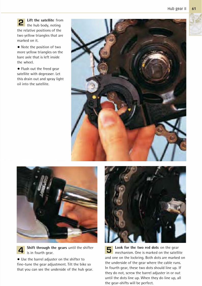
8/20/2019 Bike Repair Manual.downarchive
http://slidepdf.com/reader/full/bike-repair-manualdownarchive 61/160
Hub gear II
Lift the satellite from
the hub body, noting
the relative positions of the
two yellow triangles that are
marked on it.
• Note the position of two
more yellow triangles on the
bare axle that is left inside
the wheel.
• Flush out the freed gear
satellite with degreaser. Let
this drain out and spray light
oil into the satellite.
2
Shift through the gears until the shifter
is in fourth gear.
• Use the barrel adjuster on the shifter to
fine-tune the gear adjustment. Tilt the bike so
that you can see the underside of the hub gear.
4
Look for the two red dots on the gear
mechanism. One is marked on the satellite
and one on the lockring. Both dots are marked on
the underside of the gear where the cable runs.
In fourth gear, these two dots should line up. If
they do not, screw the barrel adjuster in or out
until the dots line up. When they do line up, all
the gear-shifts will be perfect.
5
61
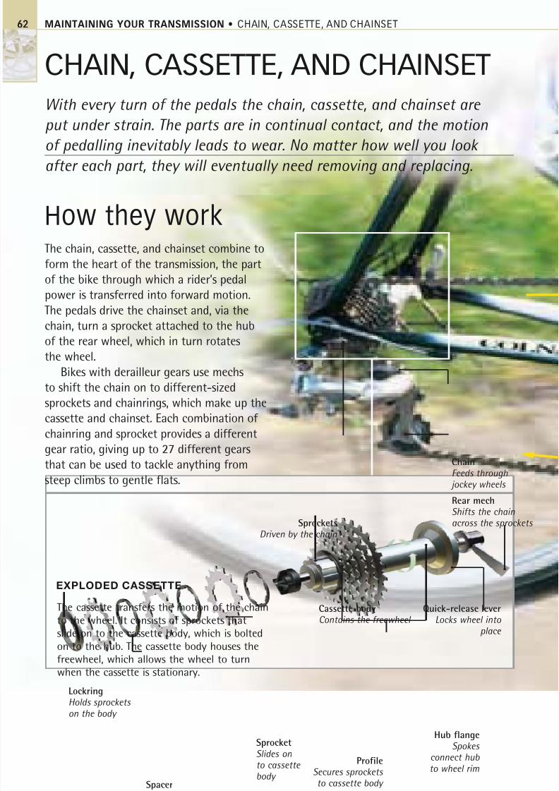
8/20/2019 Bike Repair Manual.downarchive
http://slidepdf.com/reader/full/bike-repair-manualdownarchive 62/160
MAINTAINING YOUR TRANSMISSION • CHAIN, CASSETTE, AND CHAINSET
CHAIN, CASSETTE, AND CHAINSET
With every turn of the pedals the chain, cassette, and chainset are
put under strain. The parts are in continual contact, and the motion
of pedalling inevitably leads to wear. No matter how well you look
after each part, they will eventually need removing and replacing.
How they workThe chain, cassette, and chainset combine to
form the heart of the transmission, the part
of the bike through which a rider’s pedalpower is transferred into forward motion.
The pedals drive the chainset and, via the
chain, turn a sprocket attached to the hub
of the rear wheel, which in turn rotates
the wheel.
Bikes with derailleur gears use mechs
to shift the chain on to different-sized
sprockets and chainrings, which make up the
cassette and chainset. Each combination of chainring and sprocket provides a different
gear ratio, giving up to 27 different gears
that can be used to tackle anything from
steep climbs to gentle flats.
The cassette transfers the motion of the chain
to the wheel. It consists of sprockets that
slide on to the cassette body, which is bolted
on to the hub. The cassette body houses the
freewheel, which allows the wheel to turn
when the cassette is stationary.
SprocketsDriven by the chain
ChainFeeds through
jockey wheels
EXPLODED CASSETTE
Rear mechShifts the chainacross the sprockets
Quick-release leverLocks wheel into
place
Cassette bodyContains the freewheel
Hub flangeSpokes
connect hub
to wheel rimProfile
Secures sprockets to cassette body
SprocketSlides onto cassette body
Spacer
LockringHolds sprockets
on the body
62
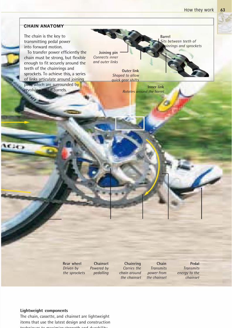
8/20/2019 Bike Repair Manual.downarchive
http://slidepdf.com/reader/full/bike-repair-manualdownarchive 63/160
How they work
ChainringCarries the
chain aroundthe chainset
ChainTransmits
power fromthe chainset
PedalTransmits
energy to the chainset
ChainsetPowered by
pedalling
Lightweight components
The chain, cassette, and chainset are lightweight
items that use the latest design and construction
techniques to maximize strength and durability
while maintaining an aerodynamic profile.
CHAIN ANATOMY
Rear wheelDriven bythe sprockets
Inner linkRotates around the barrel
BarrelSits between teeth of chainrings and sprockets
Outer linkShaped to allow quick gear shifts
Joining pin
Connects innerand outer links
The chain is the key to
transmitting pedal power
into forward motion.
To transfer power efficiently the
chain must be strong, but flexibleenough to fit securely around the
teeth of the chainrings and
sprockets. To achieve this, a series
of links articulate around joining
pins, which are surrounded by
revolving metal barrels.
63
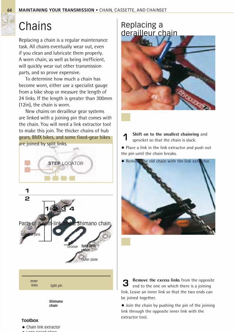
8/20/2019 Bike Repair Manual.downarchive
http://slidepdf.com/reader/full/bike-repair-manualdownarchive 64/160
STEP LOCATOR
1
2
MAINTAINING YOUR TRANSMISSION • CHAIN, CASSETTE, AND CHAINSET
ChainsReplacing a chain is a regular maintenancetask. All chains eventually wear out, evenif you clean and lubricate them properly.
A worn chain, as well as being inefficient,will quickly wear out other transmissionparts, and so prove expensive.
To determine how much a chain hasbecome worn, either use a specialist gaugefrom a bike shop or measure the length of 24 links. If the length is greater than 300mm(12in), the chain is worn.
New chains on derailleur gear systems
are linked with a joining pin that comes withthe chain. You will need a link extractor toolto make this join. The thicker chains of hubgears, BMX bikes, and some fixed-gear bikesare joined by split links.
Replacing aderailleur chain
Shift on to the smallest chainring and
sprocket so that the chain is slack.
• Place a link in the link extractor and push out
the pin until the chain breaks.
• Remove the old chain with the link extractor.
1
Remove the excess links from the opposite
end to the one on which there is a joining
link. Leave an inner link so that the two ends can
be joined together.
• Join the chain by pushing the pin of the joining
link through the opposite inner link with the
extractor tool.
3
Toolbox
Chain link extractor
Long-nosed pliers
Parts of a split-link and a Shimano chain
Split-link pins
Groove
Outer plate
Split pin
Shimanochain
Split-linkchain
Innerlinks
1 2 3 4
64
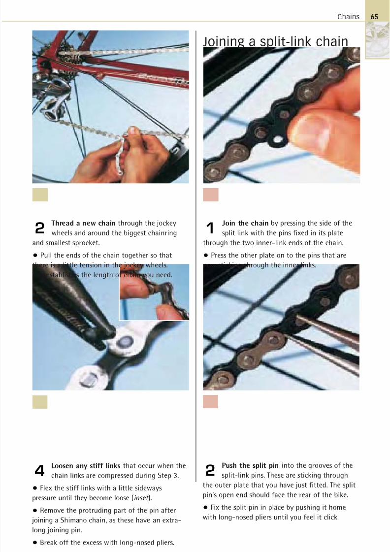
8/20/2019 Bike Repair Manual.downarchive
http://slidepdf.com/reader/full/bike-repair-manualdownarchive 65/160
Chains
Joining a split-link chain
Thread a new chain through the jockey
wheels and around the biggest chainring
and smallest sprocket.
• Pull the ends of the chain together so that
there is a little tension in the jockey wheels.
This establishes the length of chain you need.
2Join the chain by pressing the side of the
split link with the pins fixed in its plate
through the two inner-link ends of the chain.
• Press the other plate on to the pins that are
now sticking through the inner links.
1
Push the split pin into the grooves of the
split-link pins. These are sticking through
the outer plate that you have just fitted. The splitpin’s open end should face the rear of the bike.
• Fix the split pin in place by pushing it home
with long-nosed pliers until you feel it click.
2Loosen any stiff links that occur when the
chain links are compressed during Step 3.
• Flex the stiff links with a little sideways
pressure until they become loose (inset ).
• Remove the protruding part of the pin after
joining a Shimano chain, as these have an extra-
long joining pin.
• Break off the excess with long-nosed pliers.
4
65
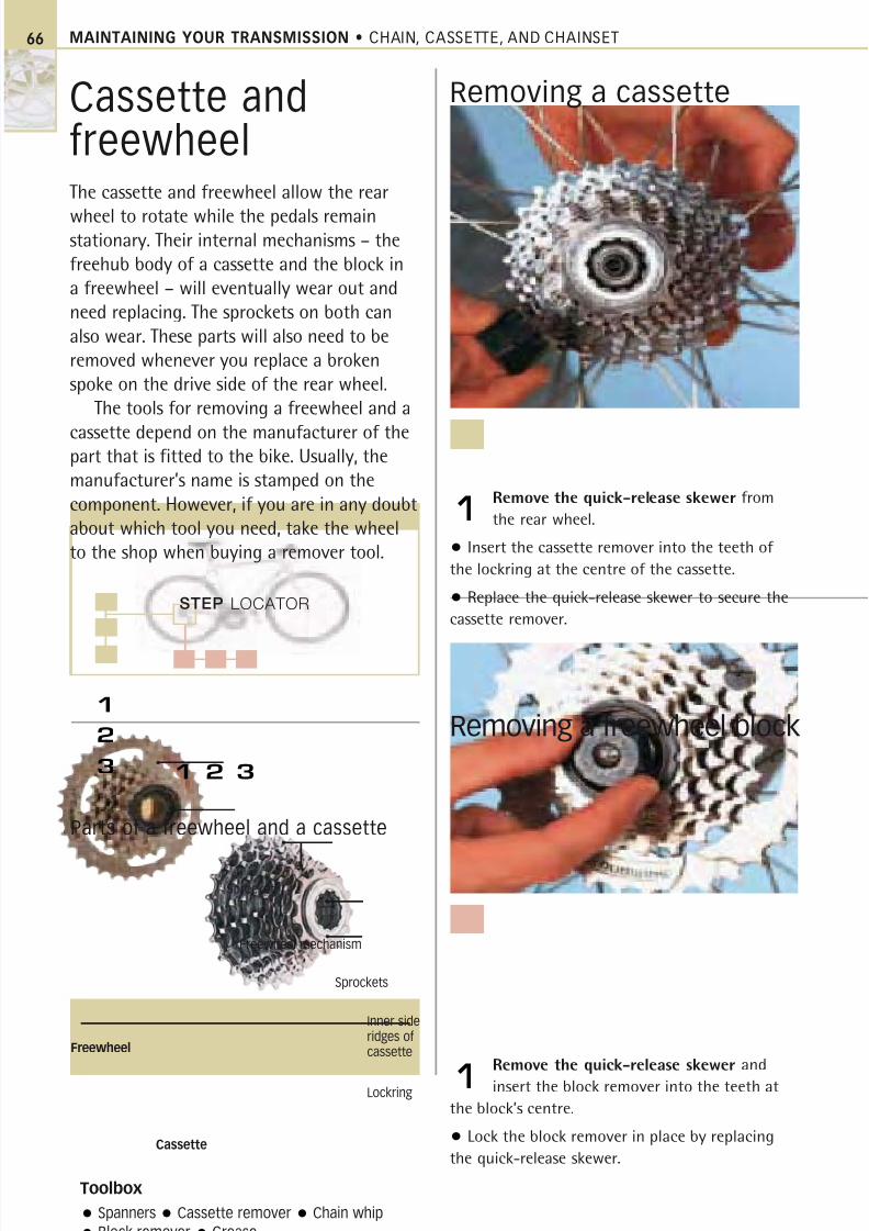
8/20/2019 Bike Repair Manual.downarchive
http://slidepdf.com/reader/full/bike-repair-manualdownarchive 66/160
STEP LOCATOR
1
3
2
MAINTAINING YOUR TRANSMISSION • CHAIN, CASSETTE, AND CHAINSET
Cassette andfreewheelThe cassette and freewheel allow the rear
wheel to rotate while the pedals remainstationary. Their internal mechanisms – the
freehub body of a cassette and the block in
a freewheel – will eventually wear out and
need replacing. The sprockets on both can
also wear. These parts will also need to be
removed whenever you replace a broken
spoke on the drive side of the rear wheel.
The tools for removing a freewheel and a
cassette depend on the manufacturer of thepart that is fitted to the bike. Usually, the
manufacturer’s name is stamped on the
component. However, if you are in any doubt
about which tool you need, take the wheel
to the shop when buying a remover tool.
Removing a cassette
Removing a freewheel block
Remove the quick-release skewer from
the rear wheel.
• Insert the cassette remover into the teeth of
the lockring at the centre of the cassette.
• Replace the quick-release skewer to secure the
cassette remover.
1
Remove the quick-release skewer and
insert the block remover into the teeth at
the block’s centre.
• Lock the block remover in place by replacing
the quick-release skewer.
1
Toolbox
Spanners Cassette remover Chain whip
Block remover Grease
Parts of a freewheel and a cassette
Sprockets
Inner sideridges of cassette
Lockring
Sprocket
Freewheel mechanism
Cassette
Freewheel
1 2 3
66
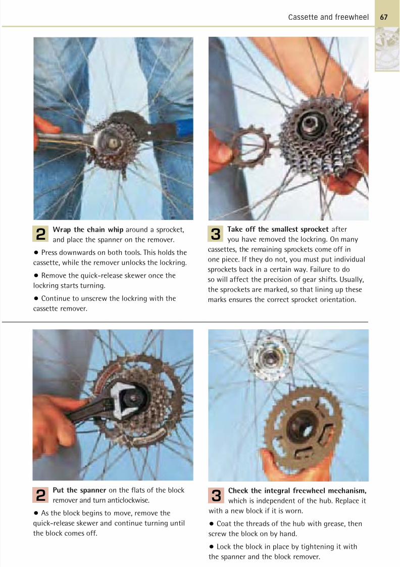
8/20/2019 Bike Repair Manual.downarchive
http://slidepdf.com/reader/full/bike-repair-manualdownarchive 67/160
Cassette and freewheel
Wrap the chain whip around a sprocket,
and place the spanner on the remover.
• Press downwards on both tools. This holds the
cassette, while the remover unlocks the lockring.
• Remove the quick-release skewer once the
lockring starts turning.
• Continue to unscrew the lockring with thecassette remover.
2
Check the integral freewheel mechanism,
which is independent of the hub. Replace it
with a new block if it is worn.
• Coat the threads of the hub with grease, then
screw the block on by hand.
• Lock the block in place by tightening it with
the spanner and the block remover.
3
Put the spanner on the flats of the block
remover and turn anticlockwise.
• As the block begins to move, remove the
quick-release skewer and continue turning until
the block comes off.
2
Take off the smallest sprocket after
you have removed the lockring. On many
cassettes, the remaining sprockets come off in
one piece. If they do not, you must put individual
sprockets back in a certain way. Failure to do
so will affect the precision of gear shifts. Usually,
the sprockets are marked, so that lining up these
marks ensures the correct sprocket orientation.
3
67
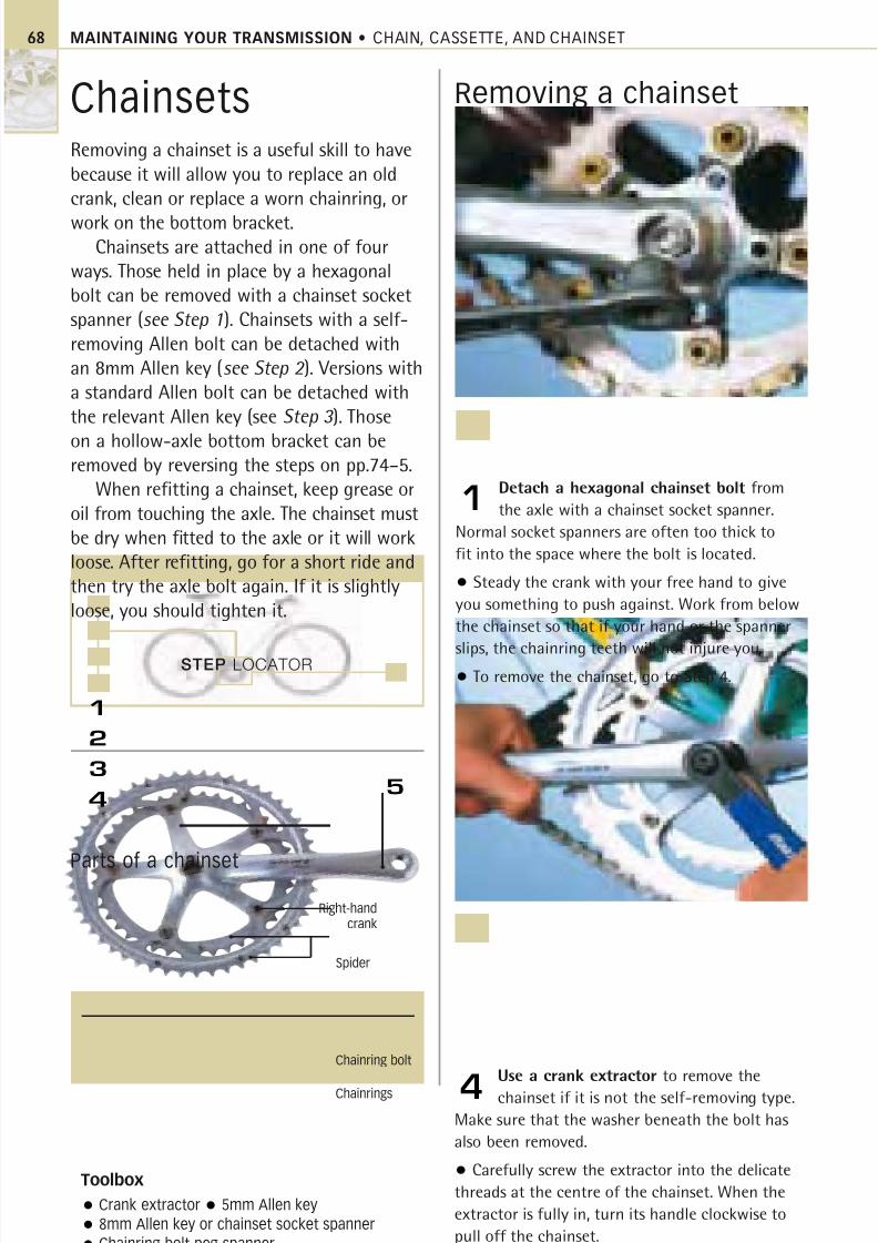
8/20/2019 Bike Repair Manual.downarchive
http://slidepdf.com/reader/full/bike-repair-manualdownarchive 68/160
STEP LOCATOR
1
5
2
3
4
MAINTAINING YOUR TRANSMISSION • CHAIN, CASSETTE, AND CHAINSET68
ChainsetsRemoving a chainset is a useful skill to havebecause it will allow you to replace an oldcrank, clean or replace a worn chainring, or
work on the bottom bracket.Chainsets are attached in one of four
ways. Those held in place by a hexagonalbolt can be removed with a chainset socketspanner (see Step 1). Chainsets with a self-removing Allen bolt can be detached withan 8mm Allen key (see Step 2 ). Versions witha standard Allen bolt can be detached withthe relevant Allen key (see Step 3 ). Those
on a hollow-axle bottom bracket can beremoved by reversing the steps on pp.74–5.
When refitting a chainset, keep grease oroil from touching the axle. The chainset mustbe dry when fitted to the axle or it will workloose. After refitting, go for a short ride andthen try the axle bolt again. If it is slightlyloose, you should tighten it.
Removing a chainset
Detach a hexagonal chainset bolt from
the axle with a chainset socket spanner.
Normal socket spanners are often too thick to
fit into the space where the bolt is located.
• Steady the crank with your free hand to give
you something to push against. Work from below
the chainset so that if your hand or the spanner
slips, the chainring teeth will not injure you.• To remove the chainset, go to Step 4.
1
Use a crank extractor to remove the
chainset if it is not the self-removing type.
Make sure that the washer beneath the bolt has
also been removed.
• Carefully screw the extractor into the delicate
threads at the centre of the chainset. When the
extractor is fully in, turn its handle clockwise to
pull off the chainset.
4
Toolbox
Crank extractor 5mm Allen key
8mm Allen key or chainset socket spanner
Chainring bolt peg spanner
Parts of a chainset
Right-handcrank
Chainring bolt
Chainrings
Spider
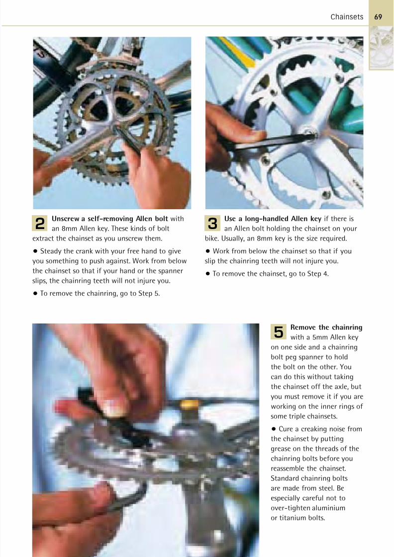
8/20/2019 Bike Repair Manual.downarchive
http://slidepdf.com/reader/full/bike-repair-manualdownarchive 69/160
Chainsets 69
Use a long-handled Allen key if there is
an Allen bolt holding the chainset on your
bike. Usually, an 8mm key is the size required.
• Work from below the chainset so that if you
slip the chainring teeth will not injure you.
• To remove the chainset, go to Step 4.
3Unscrew a self-removing Allen bolt with
an 8mm Allen key. These kinds of bolt
extract the chainset as you unscrew them.
• Steady the crank with your free hand to give
you something to push against. Work from below
the chainset so that if your hand or the spanner
slips, the chainring teeth will not injure you.
• To remove the chainring, go to Step 5.
2
Remove the chainring
with a 5mm Allen key
on one side and a chainring
bolt peg spanner to hold
the bolt on the other. You
can do this without taking
the chainset off the axle, butyou must remove it if you are
working on the inner rings of
some triple chainsets.
• Cure a creaking noise from
the chainset by putting
grease on the threads of the
chainring bolts before you
reassemble the chainset.
Standard chainring bolts
are made from steel. Beespecially careful not to
over-tighten aluminium
or titanium bolts.
5
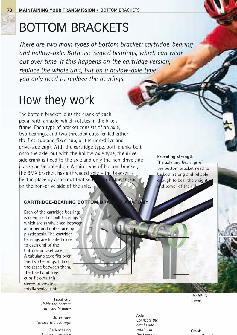
8/20/2019 Bike Repair Manual.downarchive
http://slidepdf.com/reader/full/bike-repair-manualdownarchive 70/160
MAINTAINING YOUR TRANSMISSION • BOTTOM BRACKETS
BOTTOM BRACKETS
How they workThe bottom bracket joins the crank of eachpedal with an axle, which rotates in the bike’sframe. Each type of bracket consists of an axle,two bearings, and two threaded cups (called eitherthe free cup and fixed cup, or the non-drive anddrive-side cup). With the cartridge type, both cranks boltonto the axle, but with the hollow-axle type, the drive-side crank is fixed to the axle and only the non-drive sidecrank can be bolted on. A third type of bottom bracket,the BMX bracket, has a threaded axle – the bracket isheld in place by a locknut that screws on to the threadon the non-drive side of the axle.
Each of the cartridge bearings
is composed of ball-bearings,
which are sandwiched between
an inner and outer race by
plastic seals. The cartridgebearings are located close
to each end of the
bottom-bracket axle.
A tubular sleeve fits over
the two bearings, filling
the space between them.
The fixed and free
cups fit over this
sleeve to create a
totally sealed unit.
70
CARTRIDGE-BEARING BOTTOM BRACKET ANATOMY
AxleConnects the cranks and rotates inthe bearings
Free cupScrews into the bike’s
frame
CrankTurns the axle
Fixed cupHolds the bottom
bracket in place
Outer raceHouses the bearings
Ball-bearingSupports the axle
Providing strength
The axle and bearings of
the bottom bracket need to
be both strong and reliableenough to bear the weight
and power of the rider.
There are two main types of bottom bracket: cartridge-bearing
and hollow-axle. Both use sealed bearings, which can wear
out over time. If this happens on the cartridge version,
replace the whole unit, but on a hollow-axle type
you only need to replace the bearings.
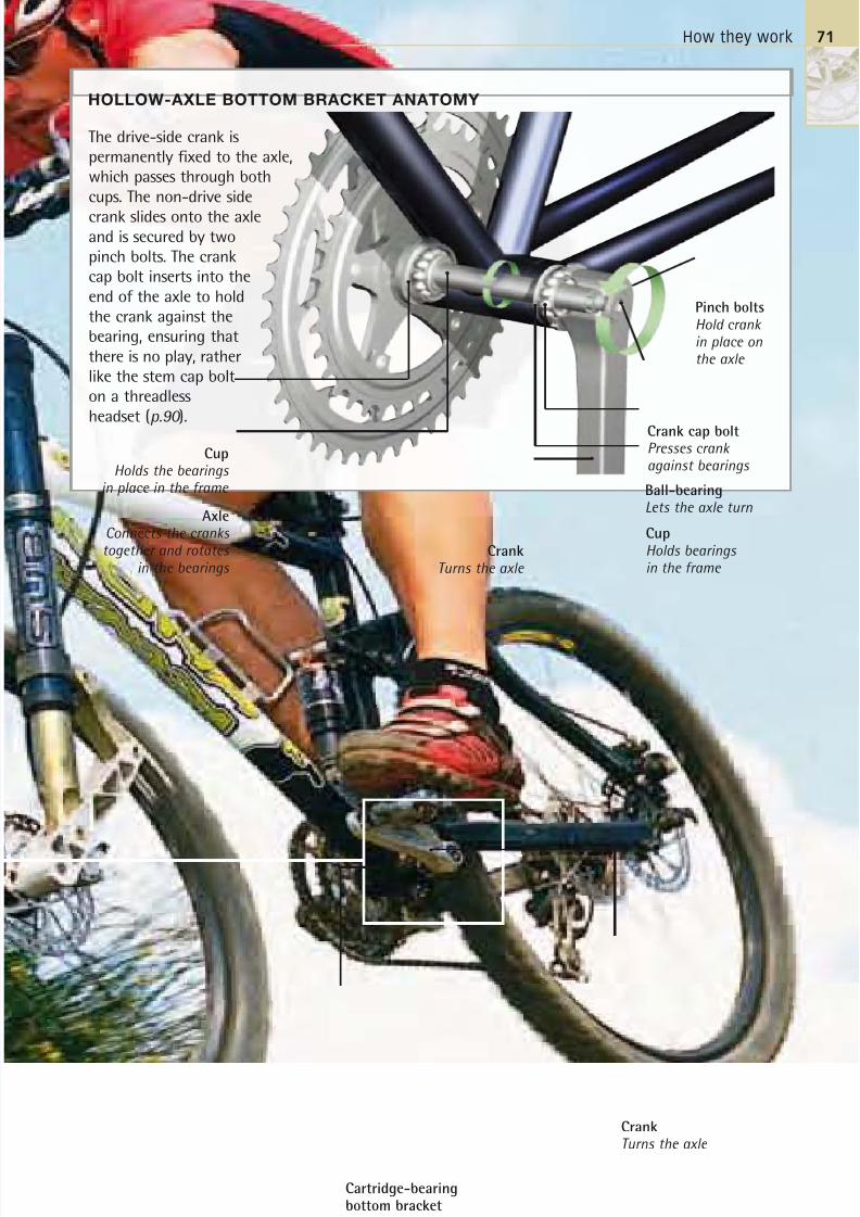
8/20/2019 Bike Repair Manual.downarchive
http://slidepdf.com/reader/full/bike-repair-manualdownarchive 71/160
How they work
The drive-side crank ispermanently fixed to the axle,which passes through bothcups. The non-drive side
crank slides onto the axleand is secured by twopinch bolts. The crankcap bolt inserts into theend of the axle to holdthe crank against thebearing, ensuring thatthere is no play, ratherlike the stem cap bolton a threadlessheadset (p.90 ).
CrankTurns the axle
71
HOLLOW-AXLE BOTTOM BRACKET ANATOMY
Ball-bearingLets the axle turn
CupHolds bearingsin the frame
CrankTurns the axle
CupHolds the bearings
in place in the frame
AxleConnects the cranks together and rotates
in the bearings
Pinch boltsHold crankin place onthe axle
Crank cap boltPresses crank against bearings
Cartridge-bearingbottom bracketAllows the smoothrotation of the axle
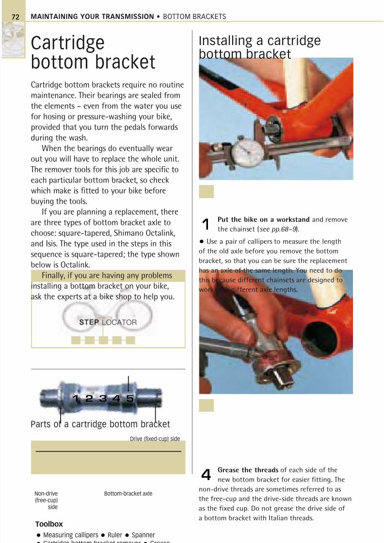
8/20/2019 Bike Repair Manual.downarchive
http://slidepdf.com/reader/full/bike-repair-manualdownarchive 72/160
MAINTAINING YOUR TRANSMISSION • BOTTOM BRACKETS
Cartridgebottom bracketCartridge bottom brackets require no routine
maintenance. Their bearings are sealed fromthe elements – even from the water you use
for hosing or pressure-washing your bike,
provided that you turn the pedals forwards
during the wash.
When the bearings do eventually wear
out you will have to replace the whole unit.
The remover tools for this job are specific to
each particular bottom bracket, so check
which make is fitted to your bike beforebuying the tools.
If you are planning a replacement, there
are three types of bottom bracket axle to
choose: square-tapered, Shimano Octalink,
and Isis. The type used in the steps in this
sequence is square-tapered; the type shown
below is Octalink.
Finally, if you are having any problems
installing a bottom bracket on your bike,ask the experts at a bike shop to help you.
Installing a cartridgebottom bracket
Put the bike on a workstand and remove
the chainset (see pp.68–9 ).
• Use a pair of callipers to measure the length
of the old axle before you remove the bottom
bracket, so that you can be sure the replacement
has an axle of the same length. You need to do
this because different chainsets are designed to
work with different axle lengths.
1
Grease the threads of each side of the
new bottom bracket for easier fitting. The
non-drive threads are sometimes referred to as
the free-cup and the drive-side threads are known
as the fixed cup. Do not grease the drive side of
a bottom bracket with Italian threads.
4
Toolbox
Measuring callipers Ruler Spanner
Cartridge bottom bracket remover Grease
Parts of a cartridge bottom bracket
Non-drive(free-cup)
side
Bottom-bracket axle
Drive (fixed-cup) side
STEP LOCATOR
1 2 3 4 5
72
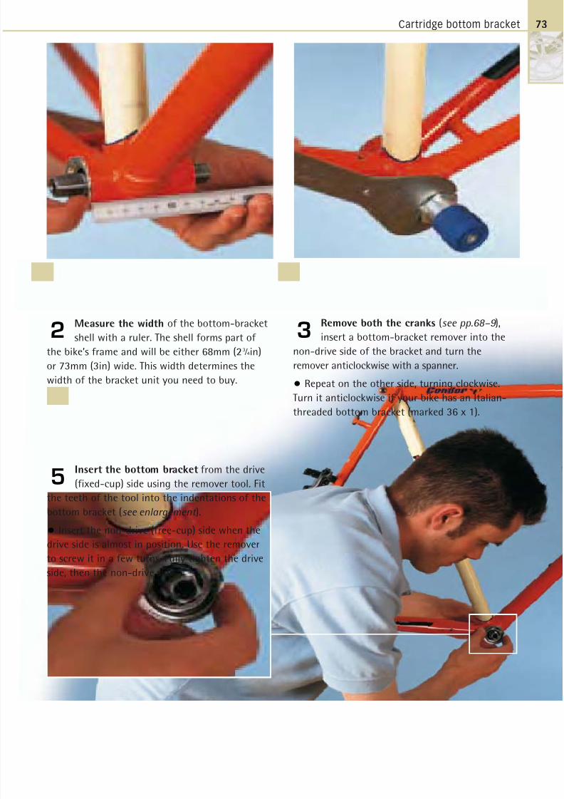
8/20/2019 Bike Repair Manual.downarchive
http://slidepdf.com/reader/full/bike-repair-manualdownarchive 73/160
Cartridge bottom bracket
Measure the width of the bottom-bracket
shell with a ruler. The shell forms part of
the bike’s frame and will be either 68mm (23 ⁄ 4in)
or 73mm (3in) wide. This width determines the
width of the bracket unit you need to buy.
2
Insert the bottom bracket from the drive
(fixed-cup) side using the remover tool. Fit
the teeth of the tool into the indentations of the
bottom bracket (see enlargement ).
• Insert the non-drive (free-cup) side when the
drive side is almost in position. Use the remover
to screw it in a few turns. Fully tighten the driveside, then the non-drive side.
5
Remove both the cranks (see pp.68–9 ),
insert a bottom-bracket remover into the
non-drive side of the bracket and turn the
remover anticlockwise with a spanner.
• Repeat on the other side, turning clockwise.
Turn it anticlockwise if your bike has an Italian-
threaded bottom bracket (marked 36 x 1).
3
73
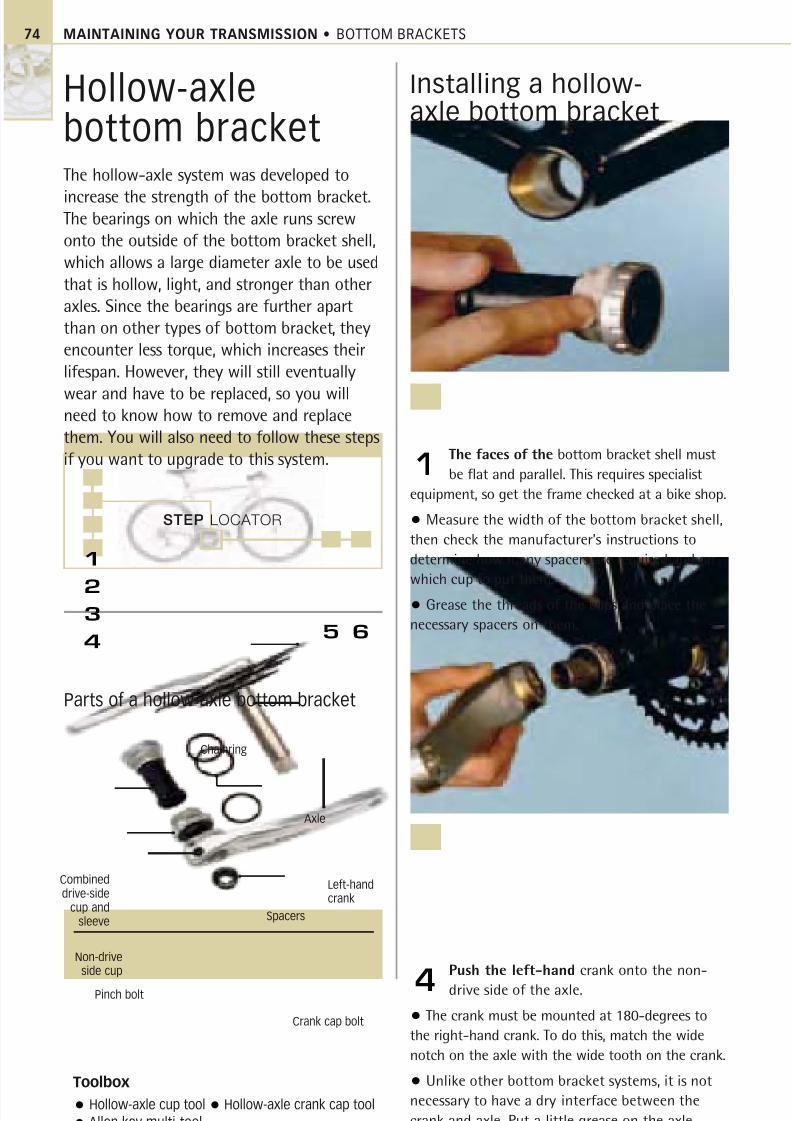
8/20/2019 Bike Repair Manual.downarchive
http://slidepdf.com/reader/full/bike-repair-manualdownarchive 74/160
STEP LOCATOR
1
2
3
4
MAINTAINING YOUR TRANSMISSION • BOTTOM BRACKETS74
Hollow-axlebottom bracketThe hollow-axle system was developed to
increase the strength of the bottom bracket.The bearings on which the axle runs screw
onto the outside of the bottom bracket shell,
which allows a large diameter axle to be used
that is hollow, light, and stronger than other
axles. Since the bearings are further apart
than on other types of bottom bracket, they
encounter less torque, which increases their
lifespan. However, they will still eventually
wear and have to be replaced, so you willneed to know how to remove and replace
them. You will also need to follow these steps
if you want to upgrade to this system.
Installing a hollow-axle bottom bracket
The faces of the bottom bracket shell must
be flat and parallel. This requires specialist
equipment, so get the frame checked at a bike shop.
• Measure the width of the bottom bracket shell,
then check the manufacturer’s instructions to
determine how many spacers are required and on
which cup to put them.
• Grease the threads of the cups and place the
necessary spacers on them.
1
Push the left-hand crank onto the non-
drive side of the axle.
• The crank must be mounted at 180-degrees to
the right-hand crank. To do this, match the wide
notch on the axle with the wide tooth on the crank.
• Unlike other bottom bracket systems, it is not
necessary to have a dry interface between the
crank and axle. Put a little grease on the axle
before you fit the crank.
4
Toolbox
Hollow-axle cup tool Hollow-axle crank cap tool
Allen key multi-tool
6
Non-driveside cup
Crank cap bolt
Left-handcrank
5
Pinch bolt
Chainring
Combineddrive-side
cup andsleeve
Axle
Spacers
Parts of a hollow-axle bottom bracket
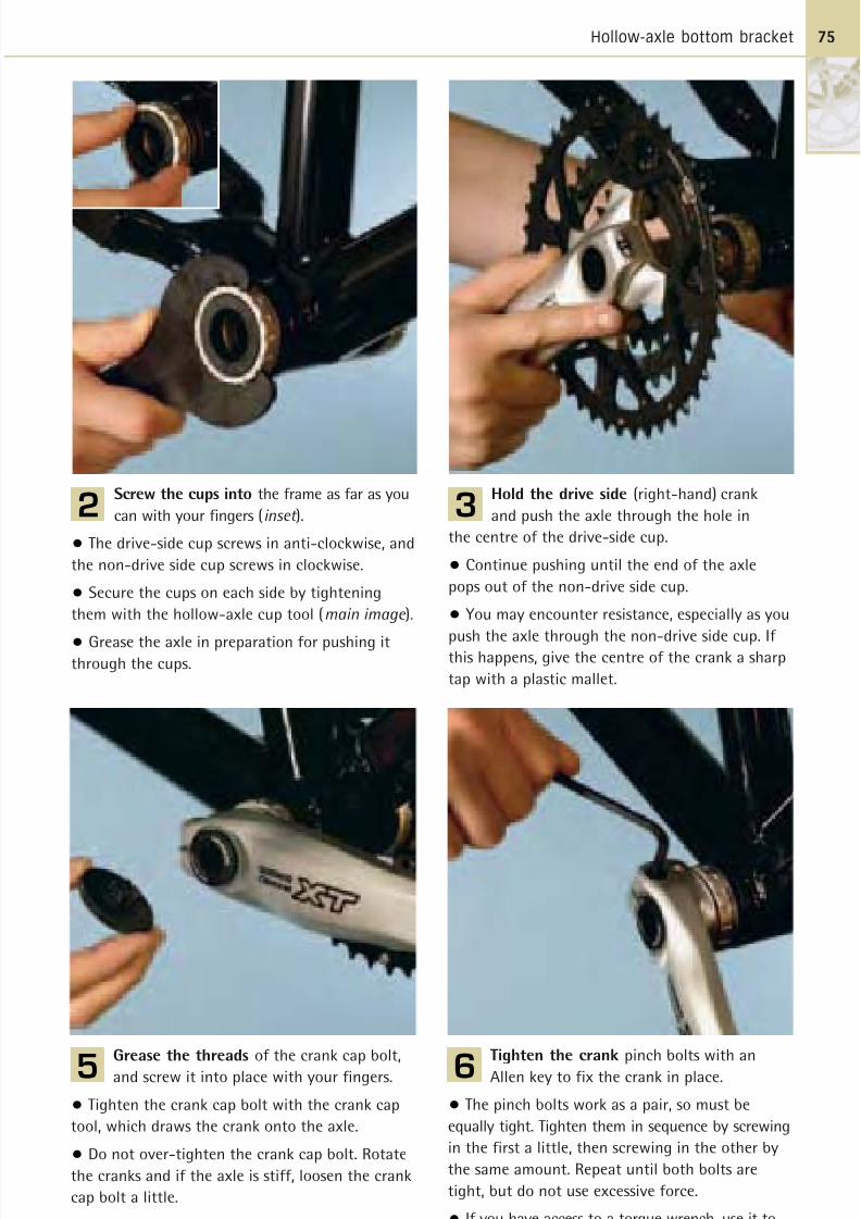
8/20/2019 Bike Repair Manual.downarchive
http://slidepdf.com/reader/full/bike-repair-manualdownarchive 75/160
Hollow-axle bottom bracket 75
Screw the cups into the frame as far as you
can with your fingers (inset ).
• The drive-side cup screws in anti-clockwise, and
the non-drive side cup screws in clockwise.
• Secure the cups on each side by tightening
them with the hollow-axle cup tool (main image ).
• Grease the axle in preparation for pushing itthrough the cups.
2Hold the drive side (right-hand) crank
and push the axle through the hole in
the centre of the drive-side cup.
• Continue pushing until the end of the axle
pops out of the non-drive side cup.
• You may encounter resistance, especially as you
push the axle through the non-drive side cup. If this happens, give the centre of the crank a sharp
tap with a plastic mallet.
3
Grease the threads of the crank cap bolt,
and screw it into place with your fingers.
• Tighten the crank cap bolt with the crank cap
tool, which draws the crank onto the axle.
• Do not over-tighten the crank cap bolt. Rotate
the cranks and if the axle is stiff, loosen the crank
cap bolt a little.
5
Tighten the crank pinch bolts with an
Allen key to fix the crank in place.
• The pinch bolts work as a pair, so must be
equally tight. Tighten them in sequence by screwing
in the first a little, then screwing in the other by
the same amount. Repeat until both bolts are
tight, but do not use excessive force.
• If you have access to a torque wrench, use it to
tighten the bolts to the manufacturer's instructions.
6
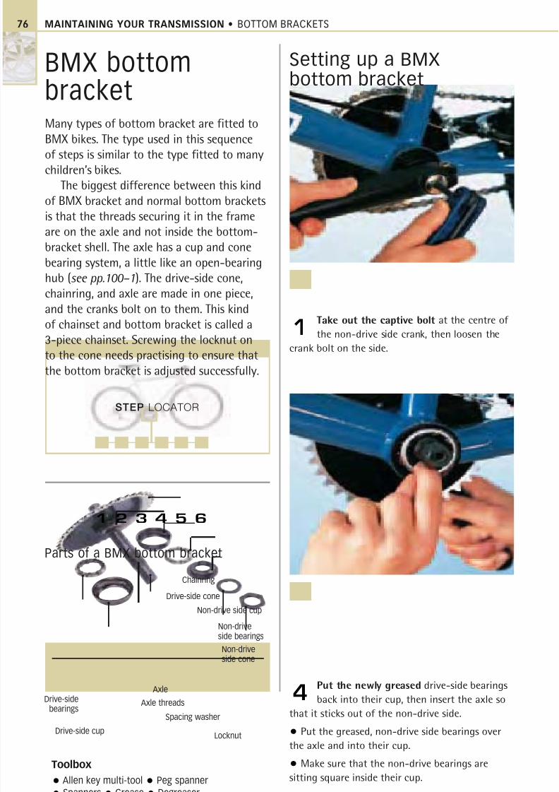
8/20/2019 Bike Repair Manual.downarchive
http://slidepdf.com/reader/full/bike-repair-manualdownarchive 76/160
MAINTAINING YOUR TRANSMISSION • BOTTOM BRACKETS
BMX bottombracketMany types of bottom bracket are fitted to
BMX bikes. The type used in this sequenceof steps is similar to the type fitted to manychildren’s bikes.
The biggest difference between this kindof BMX bracket and normal bottom bracketsis that the threads securing it in the frameare on the axle and not inside the bottom-bracket shell. The axle has a cup and conebearing system, a little like an open-bearing
hub (see pp.100–1). The drive-side cone,chainring, and axle are made in one piece,and the cranks bolt on to them. This kindof chainset and bottom bracket is called a3-piece chainset. Screwing the locknut onto the cone needs practising to ensure thatthe bottom bracket is adjusted successfully.
Setting up a BMXbottom bracket
Take out the captive bolt at the centre of
the non-drive side crank, then loosen the
crank bolt on the side.
1
Put the newly greased drive-side bearings
back into their cup, then insert the axle so
that it sticks out of the non-drive side.
• Put the greased, non-drive side bearings over
the axle and into their cup.
• Make sure that the non-drive bearings are
sitting square inside their cup.
4
Toolbox
Allen key multi-tool Peg spanner
Spanners Grease Degreaser
Parts of a BMX bottom bracket
Non-drive side cup
Chainring
Non-driveside bearings
Non-driveside cone
Drive-side cup
Drive-sidebearings
Axle threads
Spacing washer
Locknut
Drive-side cone
Axle
STEP LOCATOR
1 2 3 4 5 6
76
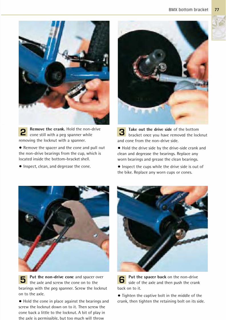
8/20/2019 Bike Repair Manual.downarchive
http://slidepdf.com/reader/full/bike-repair-manualdownarchive 77/160
BMX bottom bracket
Remove the crank. Hold the non-drive
cone still with a peg spanner while
removing the locknut with a spanner.
• Remove the spacer and the cone and pull out
the non-drive bearings from the cup, which is
located inside the bottom-bracket shell.
• Inspect, clean, and degrease the cone.
2
Put the non-drive cone and spacer over
the axle and screw the cone on to the
bearings with the peg spanner. Screw the locknut
on to the axle.
• Hold the cone in place against the bearings and
screw the locknut down on to it. Then screw the
cone back a little to the locknut. A bit of play in
the axle is permissible, but too much will throw
off the chain.
5
Put the spacer back on the non-drive
side of the axle and then push the crank
back on to it.
• Tighten the captive bolt in the middle of the
crank, then tighten the retaining bolt on its side.
6
Take out the drive side of the bottom
bracket once you have removed the locknut
and cone from the non-drive side.
• Hold the drive side by the drive-side crank and
clean and degrease the bearings. Replace any
worn bearings and grease the clean bearings.
• Inspect the cups while the drive side is out of the bike. Replace any worn cups or cones.
3
77
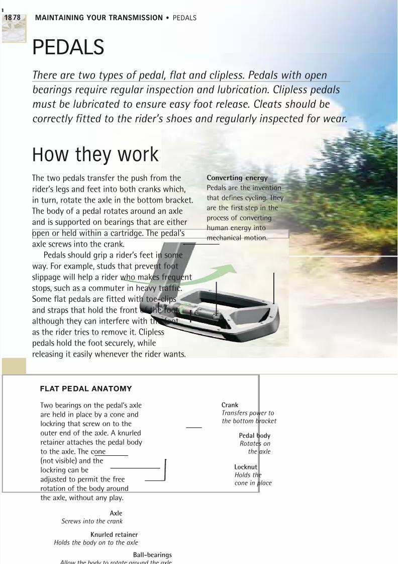
8/20/2019 Bike Repair Manual.downarchive
http://slidepdf.com/reader/full/bike-repair-manualdownarchive 78/160
MAINTAINING YOUR TRANSMISSION • PEDALS
How they workThe two pedals transfer the push from the
rider’s legs and feet into both cranks which,
in turn, rotate the axle in the bottom bracket.The body of a pedal rotates around an axle
and is supported on bearings that are either
open or held within a cartridge. The pedal’s
axle screws into the crank.
Pedals should grip a rider’s feet in some
way. For example, studs that prevent foot
slippage will help a rider who makes frequent
stops, such as a commuter in heavy traffic.
Some flat pedals are fitted with toe-clipsand straps that hold the front of the foot,
although they can interfere with the foot
as the rider tries to remove it. Clipless
pedals hold the foot securely, while
releasing it easily whenever the rider wants.
There are two types of pedal, flat and clipless. Pedals with open
bearings require regular inspection and lubrication. Clipless pedals
must be lubricated to ensure easy foot release. Cleats should be
correctly fitted to the rider’s shoes and regularly inspected for wear.
PEDALS
FLAT PEDAL ANATOMY
Converting energy
Pedals are the invention
that defines cycling. Theyare the first step in the
process of converting
human energy into
mechanical motion.
Two bearings on the pedal’s axleare held in place by a cone andlockring that screw on to theouter end of the axle. A knurledretainer attaches the pedal bodyto the axle. The cone(not visible) and thelockring can beadjusted to permit the freerotation of the body aroundthe axle, without any play.
AxleScrews into the crank
Knurled retainerHolds the body on to the axle
Pedal bodyRotates on
the axle
CrankTransfers power to the bottom bracket
LocknutHolds the cone in place
18
78
Ball-bearingsAllow the body to rotate around the axle
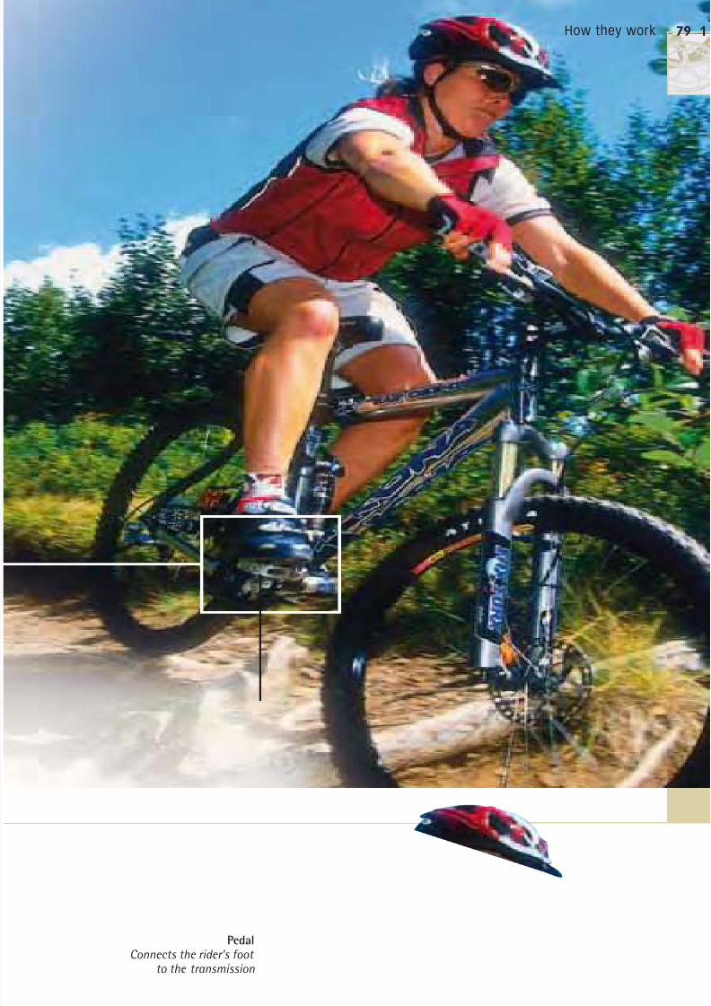
8/20/2019 Bike Repair Manual.downarchive
http://slidepdf.com/reader/full/bike-repair-manualdownarchive 79/160
Pedal
Connects the rider’s foot
to the transmission
1
79How they work
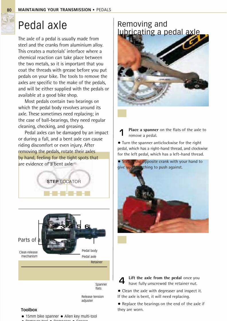
8/20/2019 Bike Repair Manual.downarchive
http://slidepdf.com/reader/full/bike-repair-manualdownarchive 80/160
MAINTAINING YOUR TRANSMISSION • PEDALS
Pedal axleThe axle of a pedal is usually made from
steel and the cranks from aluminium alloy.
This creates a materials’ interface where a
chemical reaction can take place betweenthe two metals, so it is important that you
coat the threads with grease before you put
pedals on your bike. The tools to remove the
axles are specific to the make of the pedals,
and will be either supplied with the pedals or
available at a good bike shop.
Most pedals contain two bearings on
which the pedal body revolves around its
axle. These sometimes need replacing; inthe case of ball-bearings, they need regular
cleaning, checking, and greasing.
Pedal axles can be damaged by an impact
or during a fall, and a bent axle can cause
riding discomfort or even injury. After
removing the pedals, rotate their axles
by hand, feeling for the tight spots that
are evidence of a bent axle.
Removing andlubricating a pedal axle
Place a spanner on the flats of the axle to
remove a pedal.
• Turn the spanner anticlockwise for the right
pedal, which has a right-hand thread, and clockwise
for the left pedal, which has a left-hand thread.
• Steady the opposite crank with your hand to
give you something to push against.
1
Lift the axle from the pedal once you
have fully unscrewed the retainer nut.
• Clean the axle with degreaser and inspect it.
If the axle is bent, it will need replacing.
• Replace the bearings on the end of the axle if
they are worn.
4
Toolbox
15mm bike spanner Allen key multi-tool
Remover tool Degreaser Grease
Parts of a pedal
Pedal bodyCleat-releasemechanism
Release tensionadjuster
Retainer
Pedal axle
Spannerflats
80
STEP LOCATOR
1 2 3 4 5 6
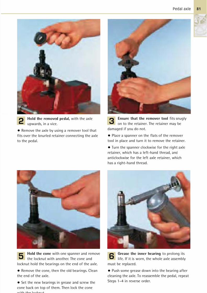
8/20/2019 Bike Repair Manual.downarchive
http://slidepdf.com/reader/full/bike-repair-manualdownarchive 81/160
Pedal axle
Hold the removed pedal, with the axle
upwards, in a vice.
• Remove the axle by using a remover tool that
fits over the knurled retainer connecting the axle
to the pedal.
2
Hold the cone with one spanner and remove
the locknut with another. The cone and
locknut hold the bearings on the end of the axle.
• Remove the cone, then the old bearings. Clean
the end of the axle.
• Set the new bearings in grease and screw the
cone back on top of them. Then lock the cone
with the locknut.
5
Grease the inner bearing to prolong its
life. If it is worn, the whole axle assembly
must be replaced.
• Push some grease down into the bearing after
cleaning the axle. To reassemble the pedal, repeat
Steps 1–4 in reverse order.
6
Ensure that the remover tool fits snugly
on to the retainer. The retainer may be
damaged if you do not.
• Place a spanner on the flats of the remover
tool in place and turn it to remove the retainer.
• Turn the spanner clockwise for the right axle
retainer, which has a left-hand thread, andanticlockwise for the left axle retainer, which
has a right-hand thread.
3
81
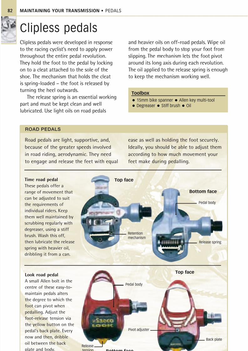
8/20/2019 Bike Repair Manual.downarchive
http://slidepdf.com/reader/full/bike-repair-manualdownarchive 82/160
MAINTAINING YOUR TRANSMISSION • PEDALS82
Clipless pedals were developed in response
to the racing cyclist’s need to apply power
throughout the entire pedal revolution.
They hold the foot to the pedal by lockingon to a cleat attached to the sole of the
shoe. The mechanism that holds the cleat
is spring-loaded – the foot is released by
turning the heel outwards.
The release spring is an essential working
part and must be kept clean and well
lubricated. Use light oils on road pedals
and heavier oils on off-road pedals. Wipe oil
from the pedal body to stop your foot from
slipping. The mechanism lets the foot pivot
around its long axis during each revolution.The oil applied to the release spring is enough
to keep the mechanism working well.
Time road pedal
These pedals offer a
range of movement that
can be adjusted to suit
the requirements of
individual riders. Keep
them well maintained by
scrubbing regularly with
degreaser, using a stiff
brush. Wash this off,
then lubricate the release
spring with heavier oil,
dribbling it from a can.
Look road pedal
A small Allen bolt in the
centre of these easy-to-
maintain pedals alters
the degree to which the
foot can pivot whenpedalling. Adjust the
foot-release tension via
the yellow button on the
pedal’s back plate. Every
now and then, dribble
oil between the back
plate and body.
Clipless pedals
Toolbox
15mm bike spanner Allen key multi-tool
Degreaser Stiff brush Oil
Release spring
Pivot adjuster
Road pedals are light, supportive, and,
because of the greater speeds involved
in road riding, aerodynamic. They need
to engage and release the feet with equal
ease as well as holding the foot securely.
Ideally, you should be able to adjust them
according to how much movement your
feet make during pedalling.
ROAD PEDALS
Pedal body
Releasetension
adjuster
Top face
Bottom face
Top face
Bottom face
Retentionmechanism
Pedal body
Back plate
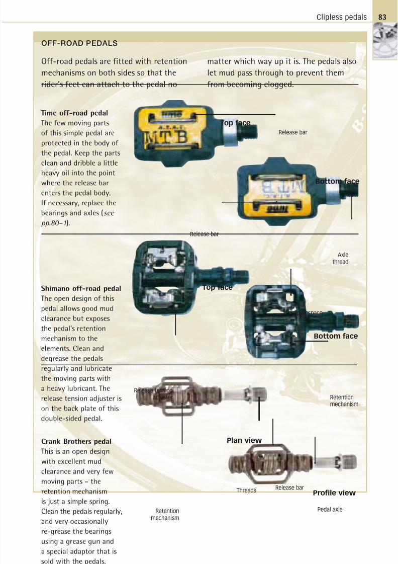
8/20/2019 Bike Repair Manual.downarchive
http://slidepdf.com/reader/full/bike-repair-manualdownarchive 83/160
Clipless pedals 83
Time off-road pedal
The few moving parts
of this simple pedal are
protected in the body of
the pedal. Keep the parts
clean and dribble a little
heavy oil into the point
where the release bar
enters the pedal body.
If necessary, replace the
bearings and axles (see
pp.80–1).
Release tension
adjuster
Release bar
Off-road pedals are fitted with retention
mechanisms on both sides so that the
rider’s feet can attach to the pedal no
matter which way up it is. The pedals also
let mud pass through to prevent them
from becoming clogged.
Shimano off-road pedal
The open design of thispedal allows good mud
clearance but exposes
the pedal’s retention
mechanism to the
elements. Clean and
degrease the pedals
regularly and lubricate
the moving parts with
a heavy lubricant. The
release tension adjuster is
on the back plate of this
double-sided pedal.
Crank Brothers pedal
This is an open design
with excellent mud
clearance and very few
moving parts – the
retention mechanismis just a simple spring.
Clean the pedals regularly,
and very occasionally
re-grease the bearings
using a grease gun and
a special adaptor that is
sold with the pedals.
OFF-ROAD PEDALS
Axlethread
Retentionmechanism
Bottom face
Bottom face
Plan view
Profile view
Top face
Top face
Release bar
Open space
Retentionmechanism
Threads Release bar
Pedal axle
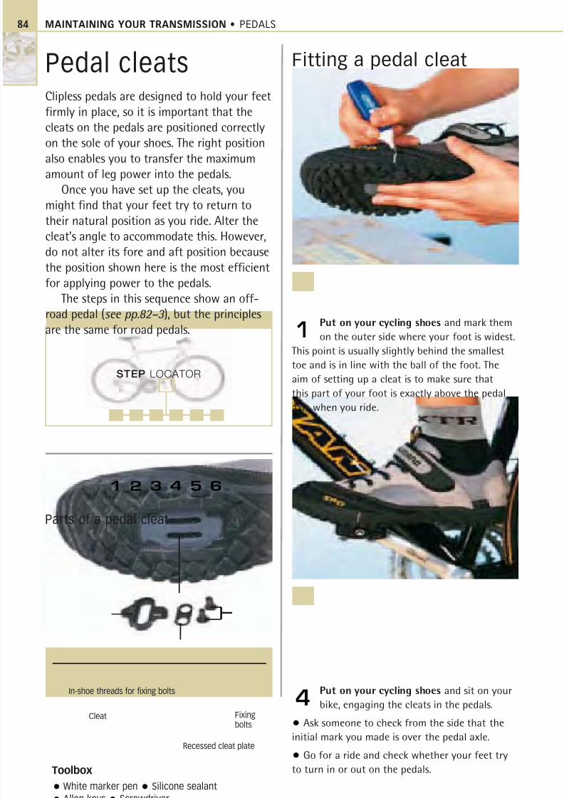
8/20/2019 Bike Repair Manual.downarchive
http://slidepdf.com/reader/full/bike-repair-manualdownarchive 84/160
MAINTAINING YOUR TRANSMISSION • PEDALS
Pedal cleatsClipless pedals are designed to hold your feetfirmly in place, so it is important that thecleats on the pedals are positioned correctly
on the sole of your shoes. The right positionalso enables you to transfer the maximumamount of leg power into the pedals.
Once you have set up the cleats, youmight find that your feet try to return totheir natural position as you ride. Alter thecleat’s angle to accommodate this. However,do not alter its fore and aft position becausethe position shown here is the most efficient
for applying power to the pedals.The steps in this sequence show an off-
road pedal (see pp.82–3 ), but the principlesare the same for road pedals.
Fitting a pedal cleat
Put on your cycling shoes and mark them
on the outer side where your foot is widest.
This point is usually slightly behind the smallest
toe and is in line with the ball of the foot. The
aim of setting up a cleat is to make sure that
this part of your foot is exactly above the pedal
axle when you ride.
1
Put on your cycling shoes and sit on your
bike, engaging the cleats in the pedals.
• Ask someone to check from the side that the
initial mark you made is over the pedal axle.
• Go for a ride and check whether your feet try
to turn in or out on the pedals.
4
Toolbox
White marker pen Silicone sealant
Allen keys Screwdriver
Fixingbolts
Cleat
Recessed cleat plate
In-shoe threads for fixing bolts
STEP LOCATOR
1 2 3 4 5 6
Parts of a pedal cleat
84
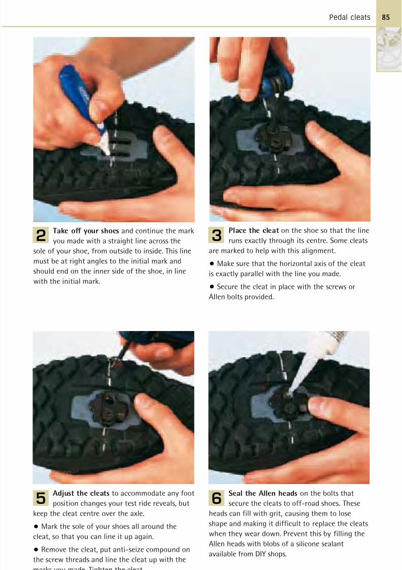
8/20/2019 Bike Repair Manual.downarchive
http://slidepdf.com/reader/full/bike-repair-manualdownarchive 85/160
Pedal cleats
Take off your shoes and continue the mark
you made with a straight line across the
sole of your shoe, from outside to inside. This line
must be at right angles to the initial mark and
should end on the inner side of the shoe, in line
with the initial mark.
2
Adjust the cleats to accommodate any foot
position changes your test ride reveals, but
keep the cleat centre over the axle.
• Mark the sole of your shoes all around the
cleat, so that you can line it up again.
• Remove the cleat, put anti-seize compound on
the screw threads and line the cleat up with the
marks you made. Tighten the cleat.
5
Seal the Allen heads on the bolts that
secure the cleats to off-road shoes. These
heads can fill with grit, causing them to lose
shape and making it difficult to replace the cleats
when they wear down. Prevent this by filling the
Allen heads with blobs of a silicone sealant
available from DIY shops.
6
Place the cleat on the shoe so that the line
runs exactly through its centre. Some cleats
are marked to help with this alignment.
• Make sure that the horizontal axis of the cleat
is exactly parallel with the line you made.
• Secure the cleat in place with the screws or
Allen bolts provided.
3
85
8/20/2019 Bike Repair Manual.downarchive
http://slidepdf.com/reader/full/bike-repair-manualdownarchive 86/160
4
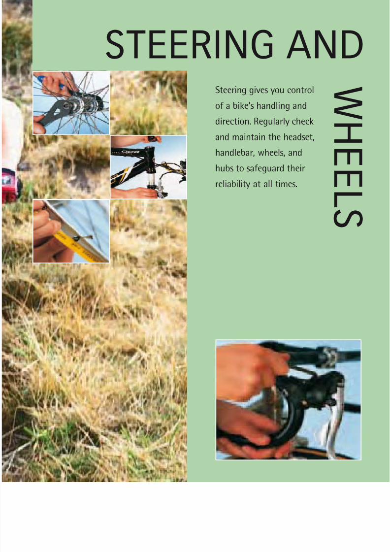
8/20/2019 Bike Repair Manual.downarchive
http://slidepdf.com/reader/full/bike-repair-manualdownarchive 87/160
STEERING ANDSteering gives you control
of a bike’s handling and
direction. Regularly check
and maintain the headset,
handlebar, wheels, and
hubs to safeguard their
reliability at all times.
WH E
E L S
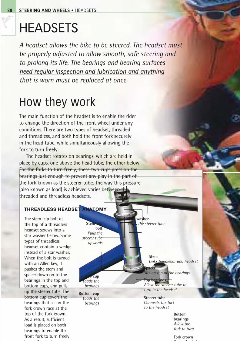
8/20/2019 Bike Repair Manual.downarchive
http://slidepdf.com/reader/full/bike-repair-manualdownarchive 88/160
STEERING AND WHEELS • HEADSETS
HEADSETS
A headset allows the bike to be steered. The headset must
be properly adjusted to allow smooth, safe steering and
to prolong its life. The bearings and bearing surfaces
need regular inspection and lubrication and anything
that is worn must be replaced at once.
How they workThe main function of the headset is to enable the riderto change the direction of the front wheel under anyconditions. There are two types of headset, threadedand threadless, and both hold the front fork securelyin the head tube, while simultaneously allowing thefork to turn freely.
The headset rotates on bearings, which are held inplace by cups, one above the head tube, the other below.For the forks to turn freely, these two cups press on thebearings just enough to prevent any play in the part of the fork known as the steerer tube. The way this pressure(also known as load) is achieved varies between thethreaded and threadless headsets.
THREADLESS HEADSET ANATOMY
Top bearingsAllow the steerer tube to turn in the headset
SpacerSits on top of the bearings
Fork crownTurns the fork
Star washerGrips the steerer tube
The stem cap bolt at
the top of a threadless
headset screws into a
star washer below. Some
types of threadless
headset contain a wedge
instead of a star washer.
When the bolt is turned
with an Allen key, it
pushes the stem and
spacer down on to the
bearings in the top and
bottom cups, and pulls
up the steerer tube. The
bottom cup covers thebearings that sit on the
fork crown race at the
top of the fork crown.
As a result, sufficient
load is placed on both
bearings to enable the
front fork to turn freely
but without play.
Stem capbolt
Pulls the
steerer tube upwards
Top cupLoads the bearings
BottombearingsAllow the
fork to turn
Bottom cup
Loads the bearings
StemLinks handlebar and headset
Steerer tubeConnects the fork to the headset
88
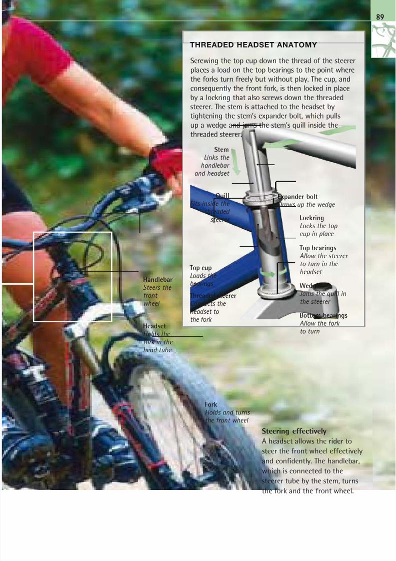
8/20/2019 Bike Repair Manual.downarchive
http://slidepdf.com/reader/full/bike-repair-manualdownarchive 89/160
Steering effectively
A headset allows the rider to
steer the front wheel effectively
and confidently. The handlebar,
which is connected to the
steerer tube by the stem, turns
the fork and the front wheel.
Screwing the top cup down the thread of the steerer
places a load on the top bearings to the point where
the forks turn freely but without play. The cup, and
consequently the front fork, is then locked in place
by a lockring that also screws down the threadedsteerer. The stem is attached to the headset by
tightening the stem’s expander bolt, which pulls
up a wedge and jams the stem’s quill inside the
threaded steerer.
THREADED HEADSET ANATOMY
Top cupLoads the bearings
StemLinks the
handlebar and headset
QuillFits inside the
threaded steerer Lockring
Locks the top cup in place
Wedge
Jams the quill inthe steerer
ForkHolds and turns the front wheel
Top bearingsAllow the steerer to turn in the headset
Bottom bearingsAllow the forkto turn
Threaded steererConnects the headset tothe fork
89
HeadsetHolds the fork in the head tube
HandlebarSteers the
front wheel
Expander boltDraws up the wedge
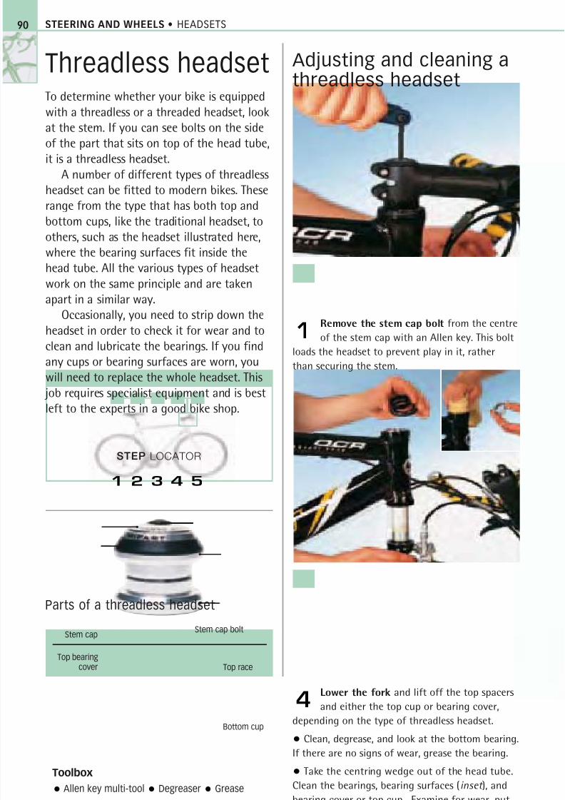
8/20/2019 Bike Repair Manual.downarchive
http://slidepdf.com/reader/full/bike-repair-manualdownarchive 90/160
STEERING AND WHEELS • HEADSETS
Threadless headsetTo determine whether your bike is equipped
with a threadless or a threaded headset, look
at the stem. If you can see bolts on the side
of the part that sits on top of the head tube,it is a threadless headset.
A number of different types of threadless
headset can be fitted to modern bikes. These
range from the type that has both top and
bottom cups, like the traditional headset, to
others, such as the headset illustrated here,
where the bearing surfaces fit inside the
head tube. All the various types of headset
work on the same principle and are takenapart in a similar way.
Occasionally, you need to strip down the
headset in order to check it for wear and to
clean and lubricate the bearings. If you find
any cups or bearing surfaces are worn, you
will need to replace the whole headset. This
job requires specialist equipment and is best
left to the experts in a good bike shop.
Adjusting and cleaning athreadless headset
Remove the stem cap bolt from the centre
of the stem cap with an Allen key. This bolt
loads the headset to prevent play in it, rather
than securing the stem.
1
Lower the fork and lift off the top spacers
and either the top cup or bearing cover,
depending on the type of threadless headset.
• Clean, degrease, and look at the bottom bearing.
If there are no signs of wear, grease the bearing.
• Take the centring wedge out of the head tube.
Clean the bearings, bearing surfaces (inset ), and
bearing cover or top cup . Examine for wear, put
new grease on the bearings and re-install.
4
Toolbox
Allen key multi-tool Degreaser Grease
Parts of a threadless headset
Bottom cup
Stem cap boltStem cap
Top bearingcover Top race
90
STEP LOCATOR
1 2 3 4 5
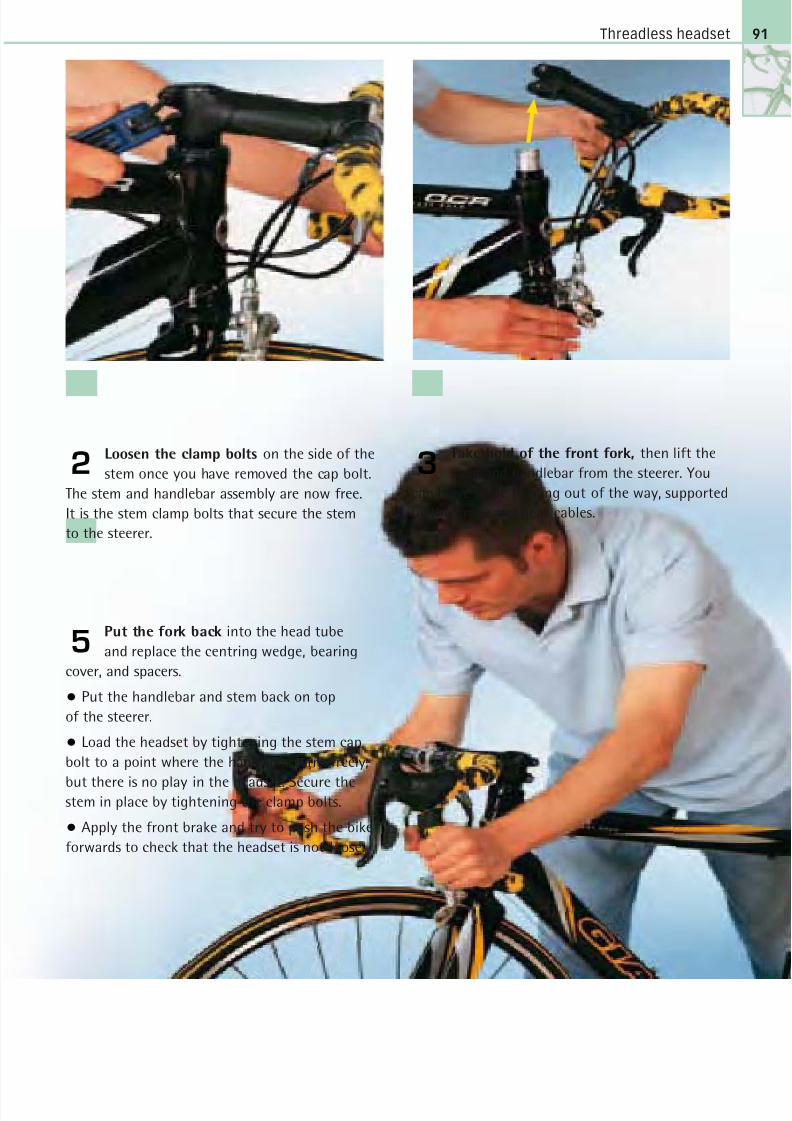
8/20/2019 Bike Repair Manual.downarchive
http://slidepdf.com/reader/full/bike-repair-manualdownarchive 91/160
Threadless headset
Loosen the clamp bolts on the side of the
stem once you have removed the cap bolt.
The stem and handlebar assembly are now free.
It is the stem clamp bolts that secure the stem
to the steerer.
2Take hold of the front fork, then lift the
stem and handlebar from the steerer. You
can leave these to hang out of the way, supported
by the brake and gear cables.
3
91
Put the fork back into the head tube
and replace the centring wedge, bearing
cover, and spacers.
• Put the handlebar and stem back on top
of the steerer.
• Load the headset by tightening the stem cap
bolt to a point where the handlebar turns freely,
but there is no play in the headset. Secure thestem in place by tightening the clamp bolts.
• Apply the front brake and try to push the bike
forwards to check that the headset is not loose.
5

8/20/2019 Bike Repair Manual.downarchive
http://slidepdf.com/reader/full/bike-repair-manualdownarchive 92/160
STEERING AND WHEELS • HEADSETS
Threaded headsetOlder bikes and children’s bikes are equippedwith threaded headsets. This type of headsetis designed to make it easy to raise and
lower the stem whenever you want tochange the height of the handlebar andadjust your riding position.
The headset’s top cup and the locknutthat holds it in place are both screwed on tothe steerer. The stem is equipped with a shaft,or quill, that fits inside the steerer. For safetyreasons, you should never raise a stem abovethe limit marked on its quill.
On some even older headsets the top cupscrews down. Its serrated top edge is held inplace by a clamp bolt on a similarly serratedlockring assembly. When the clamp bolt isloosened, the top cup screws off.
Remember to disconnect the brakesbefore you start working on the headsetand make sure that you reconnect themwhen you have finished. Before the stem
is replaced into the steerer of the headset,coat the quill with grease (see pp.30–1).
Servicing a threadedheadset
Undo the Allen bolt in the stem centre and
knock it downwards with a plastic mallet
to free the steerer. The stem is secured into the
steerer by an expander bolt which, as it is
tightened, draws a wedge up inside the quill.
• Lift the stem from the steerer.
1
Degrease all the bearing surfaces of the
top and bottom cups, and of the races. You
can access the top bearings by pushing the fork
up the head tube and holding it there.
• Inspect the bearing surfaces and if any are
damaged, you need to fit a new headset – this
is best left to a good bike shop.
4
Toolbox
6mm Allen key Grease Degreaser 30mm
and 32mm headset spanners Plastic mallet
Parts of a threaded headset
Fork crown race
Top cup
Bottom cup
LocknutSpacer
Top race
92
STEP LOCATOR
1 2 3 4 5 6
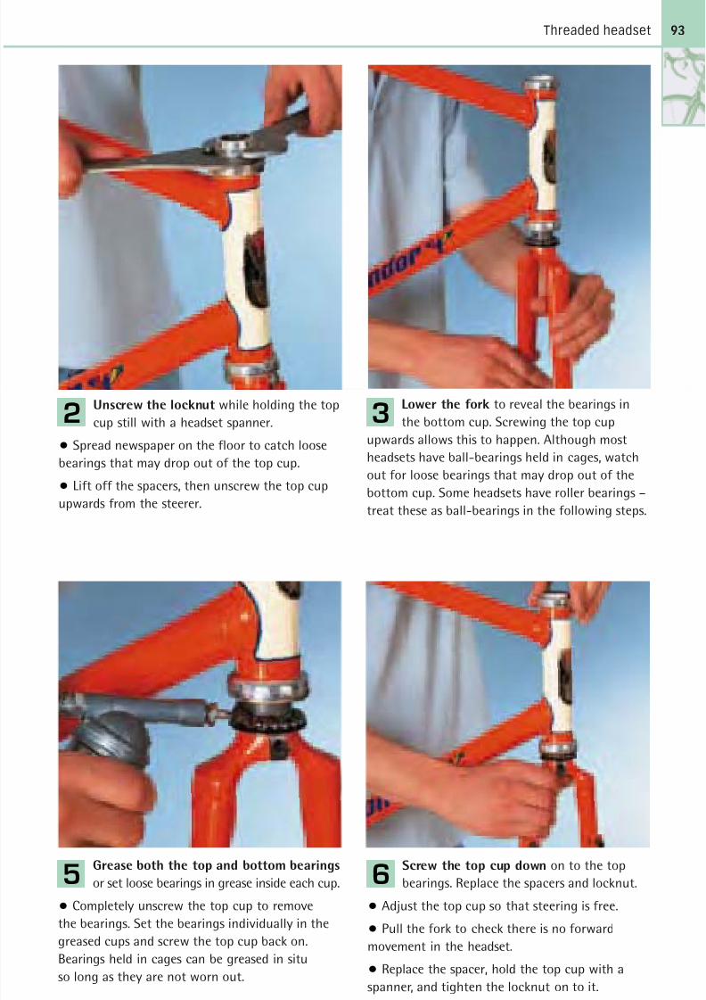
8/20/2019 Bike Repair Manual.downarchive
http://slidepdf.com/reader/full/bike-repair-manualdownarchive 93/160
Threaded headset
Unscrew the locknut while holding the top
cup still with a headset spanner.
• Spread newspaper on the floor to catch loose
bearings that may drop out of the top cup.
• Lift off the spacers, then unscrew the top cup
upwards from the steerer.
2
Grease both the top and bottom bearings
or set loose bearings in grease inside each cup.
• Completely unscrew the top cup to remove
the bearings. Set the bearings individually in the
greased cups and screw the top cup back on.
Bearings held in cages can be greased in situ
so long as they are not worn out.
5
Screw the top cup down on to the top
bearings. Replace the spacers and locknut.
• Adjust the top cup so that steering is free.
• Pull the fork to check there is no forward
movement in the headset.
• Replace the spacer, hold the top cup with a
spanner, and tighten the locknut on to it.
• Replace the stem and handlebar.
6
Lower the fork to reveal the bearings in
the bottom cup. Screwing the top cup
upwards allows this to happen. Although most
headsets have ball-bearings held in cages, watch
out for loose bearings that may drop out of the
bottom cup. Some headsets have roller bearings –
treat these as ball-bearings in the following steps.
3
93
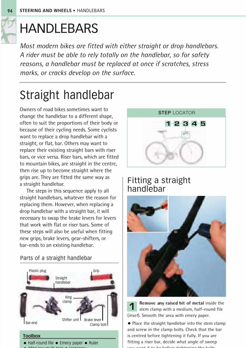
8/20/2019 Bike Repair Manual.downarchive
http://slidepdf.com/reader/full/bike-repair-manualdownarchive 94/160
STEERING AND WHEELS • HANDLEBARS
Owners of road bikes sometimes want to
change the handlebar to a different shape,
often to suit the proportions of their body orbecause of their cycling needs. Some cyclists
want to replace a drop handlebar with a
straight, or flat, bar. Others may want to
replace their existing straight bars with riser
bars, or vice versa. Riser bars, which are fitted
to mountain bikes, are straight in the centre,
then rise up to become straight where the
grips are. They are fitted the same way as
a straight handlebar.The steps in this sequence apply to all
straight handlebars, whatever the reason for
replacing them. However, when replacing a
drop handlebar with a straight bar, it will
necessary to swap the brake levers for levers
that work with flat or riser bars. Some of
these steps will also be useful when fitting
new grips, brake levers, gear-shifters, or
bar-ends to an existing handlebar.
Fitting a straighthandlebar
Remove any raised bit of metal inside thestem clamp with a medium, half-round file
(inset ). Smooth the area with emery paper.
• Place the straight handlebar into the stem clamp
and screw in the clamp bolts. Check that the bar
is centred before tightening it fully. If you are
fitting a riser bar, decide what angle of sweep
you want it to be before tightening the bolts.
1
Toolbox
Half-round file Emery paper Ruler
Allen key multi-tool Hairspray
94
STEP LOCATOR
1 2 3 4 5
HANDLEBARSMost modern bikes are fitted with either straight or drop handlebars.
A rider must be able to rely totally on the handlebar, so for safety
reasons, a handlebar must be replaced at once if scratches, stress
marks, or cracks develop on the surface.
Straight handlebar
Parts of a straight handlebar
Plastic plug
Straighthandlebar
Brake lever
Clamp bolt
Grip
Ringclamp
Shifter unitBar-end
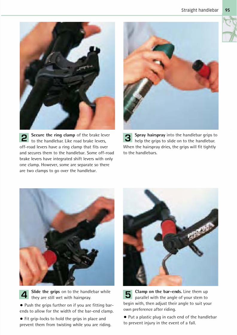
8/20/2019 Bike Repair Manual.downarchive
http://slidepdf.com/reader/full/bike-repair-manualdownarchive 95/160
Straight handlebar
Slide the grips on to the handlebar whilethey are still wet with hairspray.
• Push the grips further on if you are fitting bar-
ends to allow for the width of the bar-end clamp.
• Fit grip-locks to hold the grips in place and
prevent them from twisting while you are riding.
4Clamp on the bar-ends. Line them upparallel with the angle of your stem to
begin with, then adjust their angle to suit your
own preference after riding.
• Put a plastic plug in each end of the handlebar
to prevent injury in the event of a fall.
5
Spray hairspray into the handlebar grips to
help the grips to slide on to the handlebar.
When the hairspray dries, the grips will fit tightly
to the handlebars.
3Secure the ring clamp of the brake lever
to the handlebar. Like road brake levers,
off-road levers have a ring clamp that fits over
and secures them to the handlebar. Some off-road
brake levers have integrated shift levers with only
one clamp. However, some are separate so there
are two clamps to go over the handlebar.
2
95
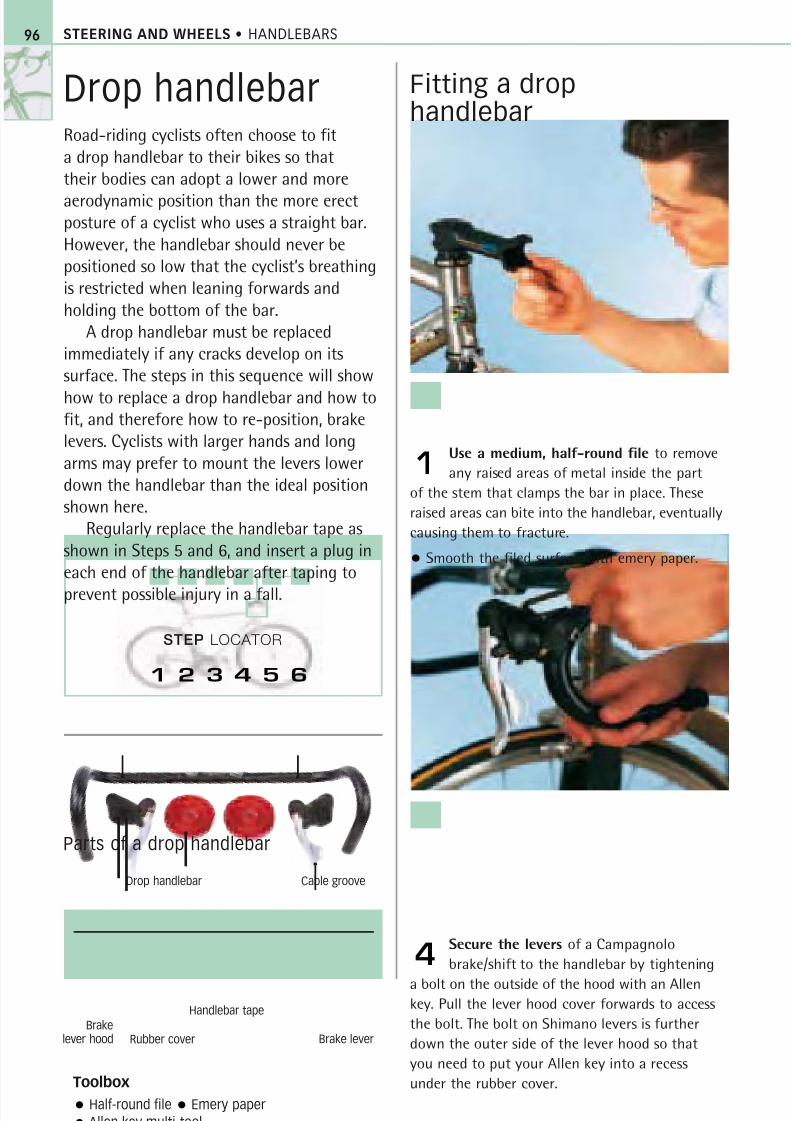
8/20/2019 Bike Repair Manual.downarchive
http://slidepdf.com/reader/full/bike-repair-manualdownarchive 96/160
STEERING AND WHEELS • HANDLEBARS
Drop handlebarRoad-riding cyclists often choose to fit
a drop handlebar to their bikes so that
their bodies can adopt a lower and more
aerodynamic position than the more erectposture of a cyclist who uses a straight bar.
However, the handlebar should never be
positioned so low that the cyclist’s breathing
is restricted when leaning forwards and
holding the bottom of the bar.
A drop handlebar must be replaced
immediately if any cracks develop on its
surface. The steps in this sequence will show
how to replace a drop handlebar and how tofit, and therefore how to re-position, brake
levers. Cyclists with larger hands and long
arms may prefer to mount the levers lower
down the handlebar than the ideal position
shown here.
Regularly replace the handlebar tape as
shown in Steps 5 and 6, and insert a plug in
each end of the handlebar after taping to
prevent possible injury in a fall.
Fitting a drophandlebar
Use a medium, half-round file to remove
any raised areas of metal inside the part
of the stem that clamps the bar in place. These
raised areas can bite into the handlebar, eventually
causing them to fracture.
• Smooth the filed surface with emery paper.
1
Secure the levers of a Campagnolo
brake/shift to the handlebar by tightening
a bolt on the outside of the hood with an Allenkey. Pull the lever hood cover forwards to access
the bolt. The bolt on Shimano levers is further
down the outer side of the lever hood so that
you need to put your Allen key into a recess
under the rubber cover.
4
Toolbox
Half-round file Emery paper
Allen key multi-tool
Parts of a drop handlebar
Brakelever hood
Drop handlebar
Handlebar tape
Rubber cover
Cable groove
96
STEP LOCATOR
1 2 3 4 5 6
Brake lever
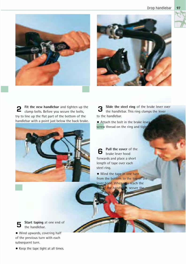
8/20/2019 Bike Repair Manual.downarchive
http://slidepdf.com/reader/full/bike-repair-manualdownarchive 97/160
Drop handlebar
Fit the new handlebar and tighten up the
clamp bolts. Before you secure the bolts,
try to line up the flat part of the bottom of the
handlebar with a point just below the back brake.
2
Start taping at one end of
the handlebar.
• Wind upwards, covering half
of the previous turn with each
subsequent turn.
• Keep the tape tight at all times.
5
Pull the cover of the
brake lever hood
forwards and place a short
length of tape over each
steel ring.
• Wind the tape in one turn
from the bottom to the top of the
lever hood. When you reach the
top of the handlebar, secure the
tape with insulating tape.
6
Slide the steel ring of the brake lever over
the handlebar. This ring clamps the lever
to the handlebar.
• Attach the bolt in the brake lever hood to the
screw thread on the ring and tighten.
3
97
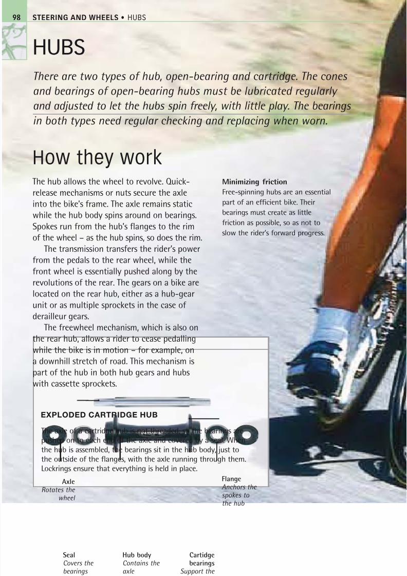
8/20/2019 Bike Repair Manual.downarchive
http://slidepdf.com/reader/full/bike-repair-manualdownarchive 98/160
STEERING AND WHEELS • HUBS
HUBS
There are two types of hub, open-bearing and cartridge. The cones
and bearings of open-bearing hubs must be lubricated regularly
and adjusted to let the hubs spin freely, with little play. The bearings
in both types need regular checking and replacing when worn.
How they workThe hub allows the wheel to revolve. Quick-
release mechanisms or nuts secure the axle
into the bike’s frame. The axle remains staticwhile the hub body spins around on bearings.
Spokes run from the hub’s flanges to the rim
of the wheel – as the hub spins, so does the rim.
The transmission transfers the rider’s power
from the pedals to the rear wheel, while the
front wheel is essentially pushed along by the
revolutions of the rear. The gears on a bike are
located on the rear hub, either as a hub-gear
unit or as multiple sprockets in the case of derailleur gears.
The freewheel mechanism, which is also on
the rear hub, allows a rider to cease pedalling
while the bike is in motion – for example, on
a downhill stretch of road. This mechanism is
part of the hub in both hub gears and hubs
with cassette sprockets.
Minimizing friction
Free-spinning hubs are an essential
part of an efficient bike. Theirbearings must create as little
friction as possible, so as not to
slow the rider’s forward progress.
The axle of a cartridge hub is not threaded, so the bearings are
pushed on to each end of the axle and covered by a seal. When
the hub is assembled, the bearings sit in the hub body, just to
the outside of the flanges, with the axle running through them.
Lockrings ensure that everything is held in place.
EXPLODED CARTRIDGE HUB
Hub bodyContains the axle
SealCovers the bearings
AxleRotates the
wheel
Cartidgebearings
Support the hub body
98
FlangeAnchors the spokes to
the hub
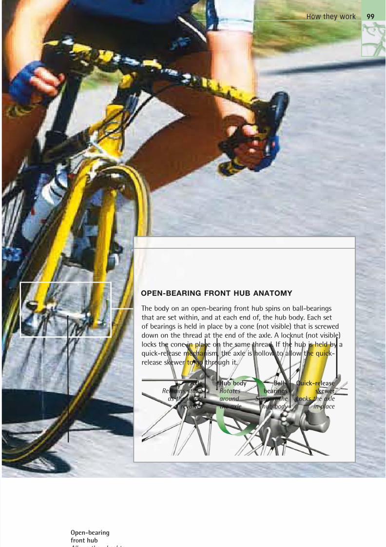
8/20/2019 Bike Repair Manual.downarchive
http://slidepdf.com/reader/full/bike-repair-manualdownarchive 99/160
How they work
OPEN-BEARING FRONT HUB ANATOMY
The body on an open-bearing front hub spins on ball-bearingsthat are set within, and at each end of, the hub body. Each setof bearings is held in place by a cone (not visible) that is screweddown on the thread at the end of the axle. A locknut (not visible)locks the cone in place on the same thread. If the hub is held by aquick-release mechanism, the axle is hollow to allow the quick-release skewer to go through it.
Ball-bearings
Support the hub body
AxleRemains static
as the wheel revolves
Hub bodyRotates around the axle
Quick-releaseskewer
Locks the axle in place
99
Open-bearingfront hubAllows the wheel to revolve smoothly
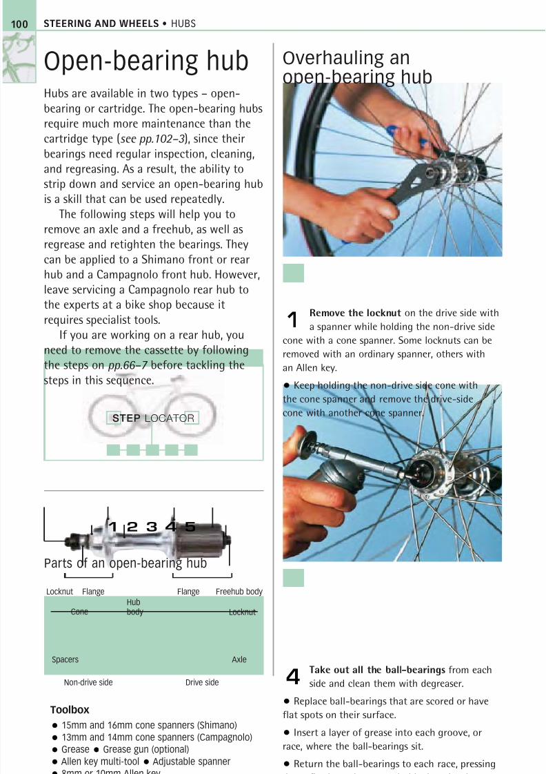
8/20/2019 Bike Repair Manual.downarchive
http://slidepdf.com/reader/full/bike-repair-manualdownarchive 100/160
STEERING AND WHEELS • HUBS
Open-bearing hubHubs are available in two types – open-bearing or cartridge. The open-bearing hubsrequire much more maintenance than the
cartridge type (see pp.102–3 ), since theirbearings need regular inspection, cleaning,and regreasing. As a result, the ability tostrip down and service an open-bearing hubis a skill that can be used repeatedly.
The following steps will help you toremove an axle and a freehub, as well asregrease and retighten the bearings. Theycan be applied to a Shimano front or rear
hub and a Campagnolo front hub. However,leave servicing a Campagnolo rear hub tothe experts at a bike shop because itrequires specialist tools.
If you are working on a rear hub, youneed to remove the cassette by followingthe steps on pp.66–7 before tackling thesteps in this sequence.
Overhauling anopen-bearing hub
Remove the locknut on the drive side with
a spanner while holding the non-drive side
cone with a cone spanner. Some locknuts can be
removed with an ordinary spanner, others with
an Allen key.
• Keep holding the non-drive side cone with
the cone spanner and remove the drive-side
cone with another cone spanner.
1
Take out all the ball-bearings from each
side and clean them with degreaser.
• Replace ball-bearings that are scored or have
flat spots on their surface.
• Insert a layer of grease into each groove, or
race, where the ball-bearings sit.
• Return the ball-bearings to each race, pressing
down firmly so the grease holds them in place.
4
Toolbox
15mm and 16mm cone spanners (Shimano)
13mm and 14mm cone spanners (Campagnolo)
Grease Grease gun (optional)
Allen key multi-tool Adjustable spanner
8mm or 10mm Allen key
Parts of an open-bearing hub
Locknut
Non-drive side Drive side
AxleSpacers
Flange
Cone
Flange
Locknut
Freehub body
Hubbody
100
STEP LOCATOR
1 2 3 4 5

8/20/2019 Bike Repair Manual.downarchive
http://slidepdf.com/reader/full/bike-repair-manualdownarchive 101/160
Open-bearing hub
Pull the axle out from the non-drive side.
Be careful not to dislodge any of the ball-
bearings as you do so.
• Clean the cones and axle and then inspect
them for damage. Check to see if the axle is bent
by rolling it on a flat surface and looking for any
irregular motion. Replace damaged cones or bent
axles immediately.
2
Fit the new hub body or
the cleaned old one by
reversing Step 3.
• Re-insert the axle from the
non-drive side.
• Tighten the drive cone up to
the bearings and check that the
axle spins freely with minimal play.
• Lock the cone into position
with the locknut.
• Use the cone spanners to check
that the non-drive cone is tight
against its locknut.
5
Insert an Allen key into the 8mm or
10mm Allen bolt located in the centre
of the freehub. This bolt holds the freehub
body on to the axle.
• Turn the key anticlockwise to remove the
freehub. You may need a bit of force to loosen
this bolt so use an Allen key with a long handle
for extra leverage.
3
101
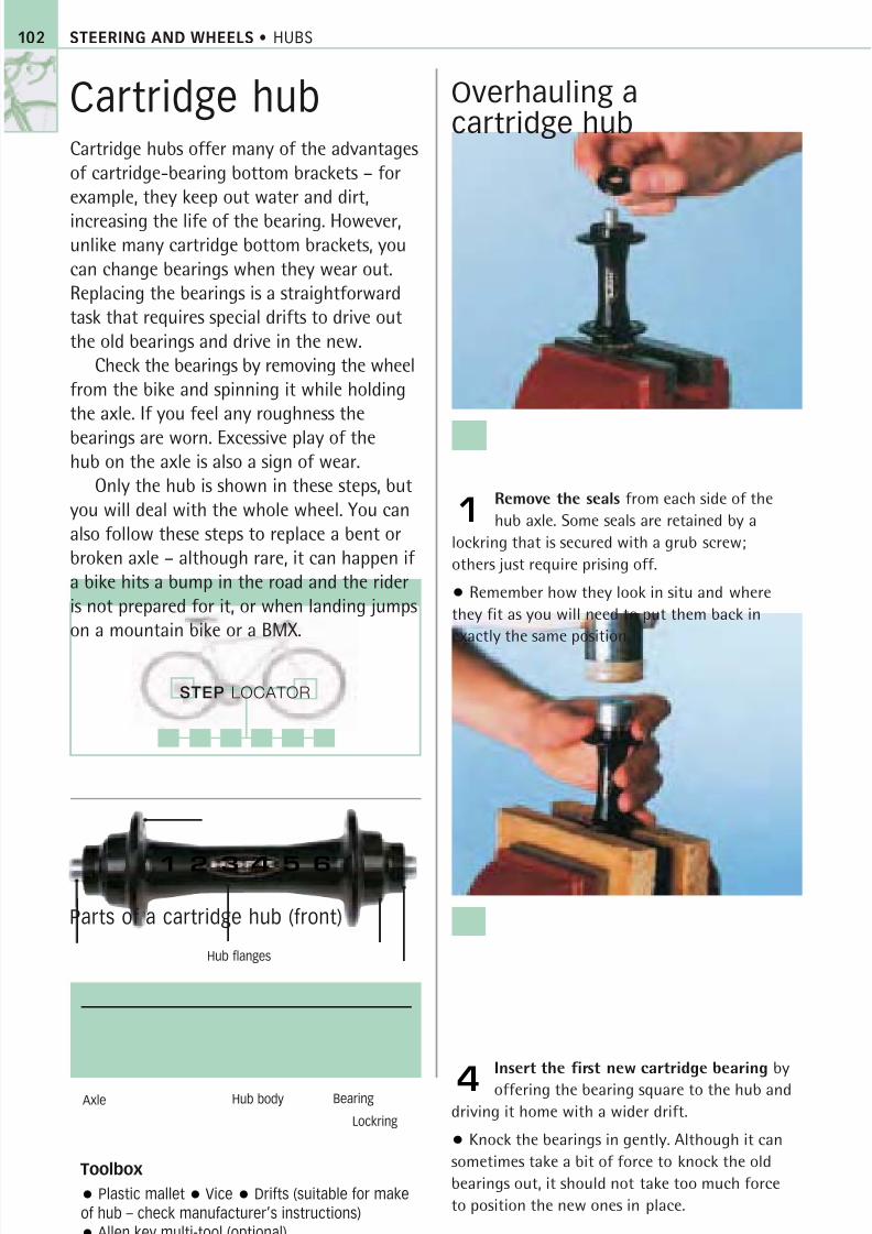
8/20/2019 Bike Repair Manual.downarchive
http://slidepdf.com/reader/full/bike-repair-manualdownarchive 102/160
STEP LOCATOR
STEERING AND WHEELS • HUBS102
Cartridge hubCartridge hubs offer many of the advantages
of cartridge-bearing bottom brackets – for
example, they keep out water and dirt,
increasing the life of the bearing. However,unlike many cartridge bottom brackets, you
can change bearings when they wear out.
Replacing the bearings is a straightforward
task that requires special drifts to drive out
the old bearings and drive in the new.
Check the bearings by removing the wheel
from the bike and spinning it while holding
the axle. If you feel any roughness the
bearings are worn. Excessive play of thehub on the axle is also a sign of wear.
Only the hub is shown in these steps, but
you will deal with the whole wheel. You can
also follow these steps to replace a bent or
broken axle – although rare, it can happen if
a bike hits a bump in the road and the rider
is not prepared for it, or when landing jumps
on a mountain bike or a BMX.
Overhauling acartridge hub
Remove the seals from each side of the
hub axle. Some seals are retained by a
lockring that is secured with a grub screw;
others just require prising off.
• Remember how they look in situ and where
they fit as you will need to put them back in
exactly the same position.
1
Insert the first new cartridge bearing by
offering the bearing square to the hub and
driving it home with a wider drift.
• Knock the bearings in gently. Although it can
sometimes take a bit of force to knock the old
bearings out, it should not take too much force
to position the new ones in place.
4
Toolbox
Plastic mallet Vice Drifts (suitable for make
of hub – check manufacturer’s instructions)
Allen key multi-tool (optional)
Parts of a cartridge hub (front)
Hub body
1 2 3 4 5 6
Hub flanges
Axle Bearing
Lockring
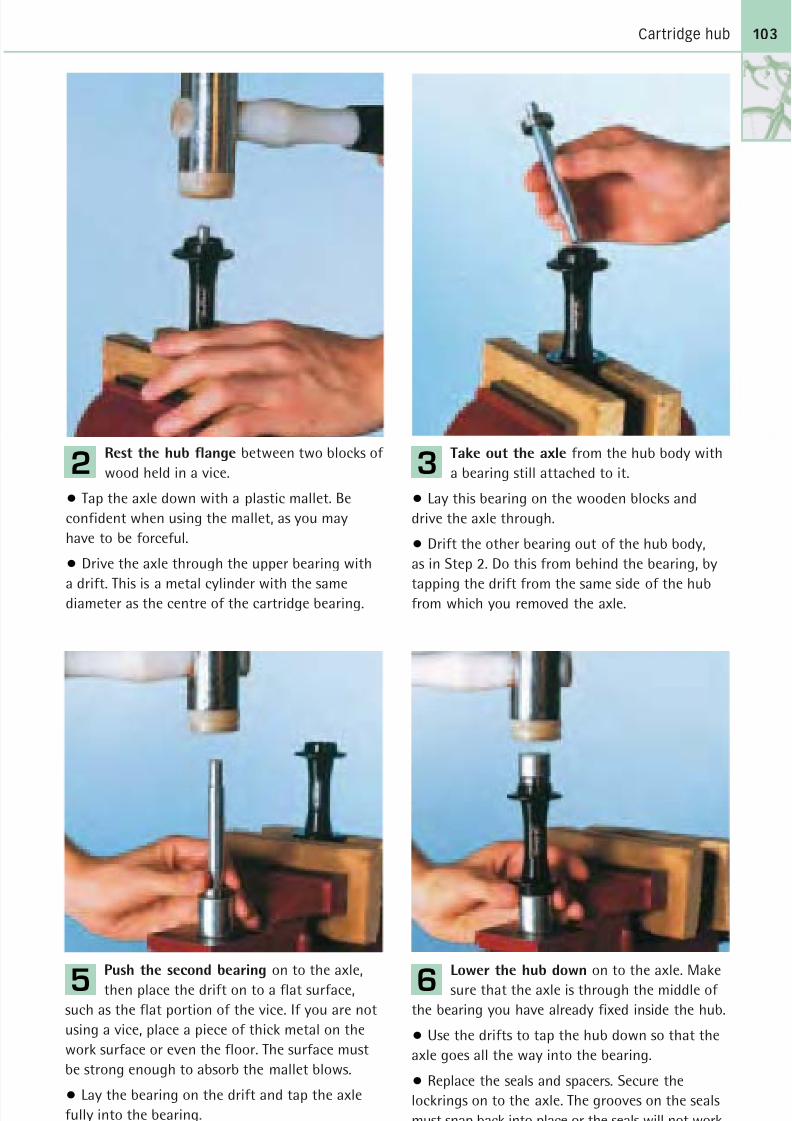
8/20/2019 Bike Repair Manual.downarchive
http://slidepdf.com/reader/full/bike-repair-manualdownarchive 103/160
Cartridge hub 103
Rest the hub flange between two blocks of
wood held in a vice.
• Tap the axle down with a plastic mallet. Be
confident when using the mallet, as you may
have to be forceful.
• Drive the axle through the upper bearing with
a drift. This is a metal cylinder with the samediameter as the centre of the cartridge bearing.
2
Push the second bearing on to the axle,
then place the drift on to a flat surface,
such as the flat portion of the vice. If you are not
using a vice, place a piece of thick metal on the
work surface or even the floor. The surface must
be strong enough to absorb the mallet blows.
• Lay the bearing on the drift and tap the axle
fully into the bearing.
5
Lower the hub down on to the axle. Make
sure that the axle is through the middle of
the bearing you have already fixed inside the hub.
• Use the drifts to tap the hub down so that the
axle goes all the way into the bearing.
• Replace the seals and spacers. Secure the
lockrings on to the axle. The grooves on the seals
must snap back into place or the seals will not work.
6
Take out the axle from the hub body with
a bearing still attached to it.
• Lay this bearing on the wooden blocks and
drive the axle through.
• Drift the other bearing out of the hub body,
as in Step 2. Do this from behind the bearing, by
tapping the drift from the same side of the hubfrom which you removed the axle.
3
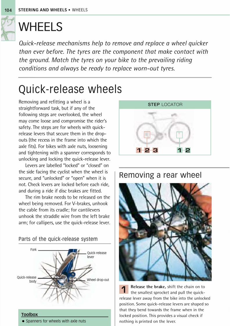
8/20/2019 Bike Repair Manual.downarchive
http://slidepdf.com/reader/full/bike-repair-manualdownarchive 104/160
STEERING AND WHEELS • WHEELS
Removing and refitting a wheel is astraightforward task, but if any of the
following steps are overlooked, the wheelmay come loose and compromise the rider’ssafety. The steps are for wheels with quick-release levers that secure them in the drop-outs (the recess in the frame into which theaxle fits). For bikes with axle nuts, looseningand tightening with a spanner corresponds tounlocking and locking the quick-release lever.
Levers are labelled “locked” or “closed” on
the side facing the cyclist when the wheel issecure, and “unlocked” or “open” when it isnot. Check levers are locked before each ride,and during a ride if disc brakes are fitted.
The rim brake needs to be released on thewheel being removed. For V-brakes, unhookthe cable from its cradle; for cantileversunhook the straddle wire from the left brakearm; for callipers, use the quick-release lever.
Removing a rear wheel
Release the brake, shift the chain on to
the smallest sprocket and pull the quick-
release lever away from the bike into the unlocked
position. Some quick-release levers are shaped so
that they bend towards the frame when in the
locked position. This provides a visual check if
nothing is printed on the lever.
1
Toolbox
Spanners for wheels with axle nuts
Parts of the quick-release system
Quick-releasebody
104
STEP LOCATOR
1 2 3 1 2
WHEELSQuick-release mechanisms help to remove and replace a wheel quicker
than ever before. The tyres are the component that make contact with
the ground. Match the tyres on your bike to the prevailing riding
conditions and always be ready to replace worn-out tyres.
Quick-release wheels
Quick-releaselever
Wheel drop-out
Fork

8/20/2019 Bike Repair Manual.downarchive
http://slidepdf.com/reader/full/bike-repair-manualdownarchive 105/160
Quick-release wheels
Removing a front wheel
Hook the chain out of the way and on tothe peg situated on the inner side of the
right seat stay (if there is one).
• Pull the rear mech back and then lift up the
rear of the bike.
• Give the tyre a sharp blow from above with
the heel of your hand if the wheel does not drop
forwards and out of the frame.
2
Lift up the bike to allow the wheel to dropout of the fork.
• Replace the front wheel by reversing Step 1.
• Push the quick-release lever behind the left
fork leg to prevent anything catching it and
opening it accidentally.
• Reconnect the brake once the wheel is locked.
2Release the brake. Pull the quick-releaselever to the unlocked position. If the
drop-out has safety lips, the wheel will not come
out of the fork at this stage. These safety lips
prevent the wheel falling out in the unlikely event
of the lever becoming unlocked while you ride.
• Use your fingers to unscrew the nut on the
opposite side of the lever until the quick-release
clears the safety lip.
1
Replace the wheel by introducing the hubaxle to the drop-outs.
• Hook the chain on to the smallest sprocket,
then push or pull the wheel backwards.
• Line up the tyre exactly in the middle of the
chainstays as you hold the wheel straight.
• Push the quick-release lever into the locked
position to secure the wheel. Reconnect the brake.
3
105

8/20/2019 Bike Repair Manual.downarchive
http://slidepdf.com/reader/full/bike-repair-manualdownarchive 106/160
STEP LOCATOR
STEERING AND WHEELS • WHEELS106
Puncture repairWhen you are out on a ride, it is much easier
to replace a punctured inner tube with an
intact tube rather than painstakingly mend
the puncture. At home, you can repair thepunctured tube with adhesive and a patch.
It is still a good idea to carry a repair kit on
every ride, because you might be unlucky
enough to get a second puncture and be
forced to repair the tube outdoors.
The main point to remember about
mending a puncture is not to rush any of
the stages. If you patiently give the glue
time to dry, closely examine the inside ofthe tyre, and carefully refit the tube, then
you will be rewarded with a successful repair.
If you miss anything or trap the inner tube,
you may get another puncture.
Mending a puncturedinner tube
Take the wheel out of the bike. Place one
tyre lever under the tyre bead and lift it off
the rim. Hook this lever around one of the spokes.
• Insert another lever under the tyre near to the
hooked lever. Push the second lever forwards and
run it around the whole circumference of the rim
to remove one side of the tyre.
• Remove the inner tube from the rim.
1
Take the tyre off the wheel, turn it inside
out and thoroughly check the inner surface.
• Remove anything that is sticking through the
tyre by pulling it out from the outside of the tyre.
4
Toolbox
Tyre levers Crayon Sandpaper Chalk
Patch adhesive Repair patches
Parts of a wheel
Inner tube
1 2 3 4 5
RimTyre Valve
Spoke
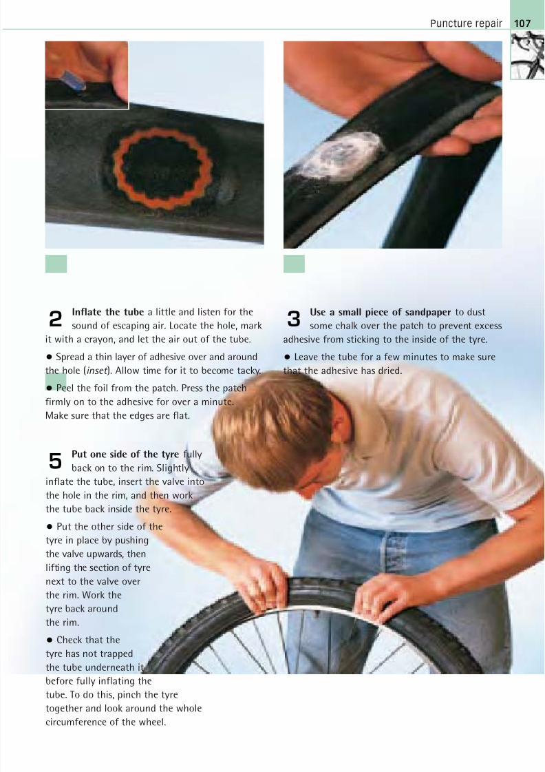
8/20/2019 Bike Repair Manual.downarchive
http://slidepdf.com/reader/full/bike-repair-manualdownarchive 107/160
Puncture repair 107
Inflate the tube a little and listen for the
sound of escaping air. Locate the hole, mark
it with a crayon, and let the air out of the tube.
• Spread a thin layer of adhesive over and around
the hole (inset ). Allow time for it to become tacky.
• Peel the foil from the patch. Press the patch
firmly on to the adhesive for over a minute.Make sure that the edges are flat.
2
Put one side of the tyre fully
back on to the rim. Slightly
inflate the tube, insert the valve into
the hole in the rim, and then work
the tube back inside the tyre.
• Put the other side of the
tyre in place by pushingthe valve upwards, then
lifting the section of tyre
next to the valve over
the rim. Work the
tyre back around
the rim.
• Check that the
tyre has not trapped
the tube underneath it
before fully inflating the
tube. To do this, pinch the tyre
together and look around the whole
circumference of the wheel.
5
Use a small piece of sandpaper to dust
some chalk over the patch to prevent excess
adhesive from sticking to the inside of the tyre.
• Leave the tube for a few minutes to make sure
that the adhesive has dried.
3
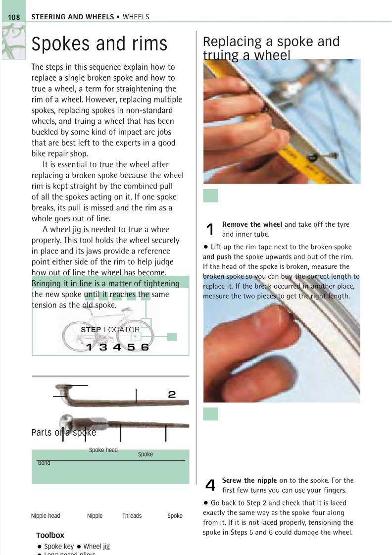
8/20/2019 Bike Repair Manual.downarchive
http://slidepdf.com/reader/full/bike-repair-manualdownarchive 108/160
STEERING AND WHEELS • WHEELS
Spokes and rimsThe steps in this sequence explain how to
replace a single broken spoke and how to
true a wheel, a term for straightening the
rim of a wheel. However, replacing multiplespokes, replacing spokes in non-standard
wheels, and truing a wheel that has been
buckled by some kind of impact are jobs
that are best left to the experts in a good
bike repair shop.
It is essential to true the wheel after
replacing a broken spoke because the wheel
rim is kept straight by the combined pull
of all the spokes acting on it. If one spokebreaks, its pull is missed and the rim as a
whole goes out of line.
A wheel jig is needed to true a wheel
properly. This tool holds the wheel securely
in place and its jaws provide a reference
point either side of the rim to help judge
how out of line the wheel has become.
Bringing it in line is a matter of tightening
the new spoke until it reaches the sametension as the old spoke.
Replacing a spoke andtruing a wheel
Remove the wheel and take off the tyre
and inner tube.
• Lift up the rim tape next to the broken spoke
and push the spoke upwards and out of the rim.
If the head of the spoke is broken, measure the
broken spoke so you can buy the correct length to
replace it. If the break occurred in another place,
measure the two pieces to get the right length.
1
Screw the nipple on to the spoke. For the
first few turns you can use your fingers.
• Go back to Step 2 and check that it is laced
exactly the same way as the spoke four along
from it. If it is not laced properly, tensioning the
spoke in Steps 5 and 6 could damage the wheel.
4
Toolbox
Spoke key Wheel jig
Long-nosed pliers
Parts of a spoke
108
STEP LOCATOR
2
1 3 4 5 6
Nipple head
Spoke
Bend
Nipple Threads Spoke
Spoke head
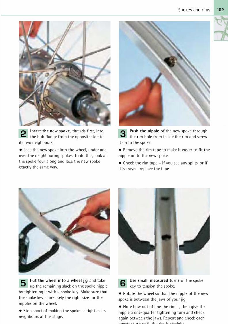
8/20/2019 Bike Repair Manual.downarchive
http://slidepdf.com/reader/full/bike-repair-manualdownarchive 109/160
Spokes and rims
Insert the new spoke, threads first, into
the hub flange from the opposite side to
its two neighbours.
• Lace the new spoke into the wheel, under and
over the neighbouring spokes. To do this, look at
the spoke four along and lace the new spoke
exactly the same way.
2
Put the wheel into a wheel jig and take
up the remaining slack on the spoke nipple
by tightening it with a spoke key. Make sure that
the spoke key is precisely the right size for the
nipples on the wheel.
• Stop short of making the spoke as tight as its
neighbours at this stage.
5
Use small, measured turns of the spoke
key to tension the spoke.
• Rotate the wheel so that the nipple of the new
spoke is between the jaws of your jig.
• Note how out of line the rim is, then give the
nipple a one-quarter tightening turn and check
again between the jaws. Repeat and check each
quarter turn until the rim is straight.
6
Push the nipple of the new spoke through
the rim hole from inside the rim and screw
it on to the spoke.
• Remove the rim tape to make it easier to fit the
nipple on to the new spoke.
• Check the rim tape – if you see any splits, or if
it is frayed, replace the tape.
3
109
8/20/2019 Bike Repair Manual.downarchive
http://slidepdf.com/reader/full/bike-repair-manualdownarchive 110/160
5
8/20/2019 Bike Repair Manual.downarchive
http://slidepdf.com/reader/full/bike-repair-manualdownarchive 111/160
Trustworthy brakes are
a bike’s most important
component. The braking
system needs to be
adjusted and serviced
with careful precision to
guarantee a rider’s safety
in all conditions.
B R A K
E S
ADJUSTING YOUR
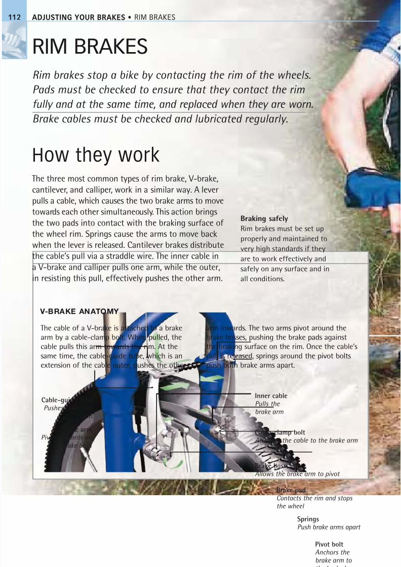
8/20/2019 Bike Repair Manual.downarchive
http://slidepdf.com/reader/full/bike-repair-manualdownarchive 112/160
ADJUSTING YOUR BRAKES • RIM BRAKES112
RIM BRAKES
Rim brakes stop a bike by contacting the rim of the wheels.
Pads must be checked to ensure that they contact the rim
fully and at the same time, and replaced when they are worn.
Brake cables must be checked and lubricated regularly.
How they workThe three most common types of rim brake, V-brake,
cantilever, and calliper, work in a similar way. A lever
pulls a cable, which causes the two brake arms to movetowards each other simultaneously. This action brings
the two pads into contact with the braking surface of
the wheel rim. Springs cause the arms to move back
when the lever is released. Cantilever brakes distribute
the cable’s pull via a straddle wire. The inner cable in
a V-brake and calliper pulls one arm, while the outer,
in resisting this pull, effectively pushes the other arm.
Braking safely
Rim brakes must be set up
properly and maintained to
very high standards if they
are to work effectively and
safely on any surface and in
all conditions.
The cable of a V-brake is attached to a brake
arm by a cable-clamp bolt. When pulled, the
cable pulls this arm towards the rim. At the
same time, the cable-guide tube, which is an
extension of the cable outer, pushes the other
arm inwards. The two arms pivot around the
brake bosses, pushing the brake pads against
the braking surface on the rim. Once the cable’s
pull is released, springs around the pivot bolts
push both brake arms apart.
V-BRAKE ANATOMY
Brake pad
Contacts the rim and stopsthe wheel
Brake armPivots inwards on
a brake boss
Cable-clamp boltAttaches the cable to the brake arm
Cable-guide tubePushes the brake
arm
Pivot boltAnchors the brake arm tothe brake boss
Inner cablePulls the brake arm
Brake bossAllows the brake arm to pivot
SpringsPush brake arms apart
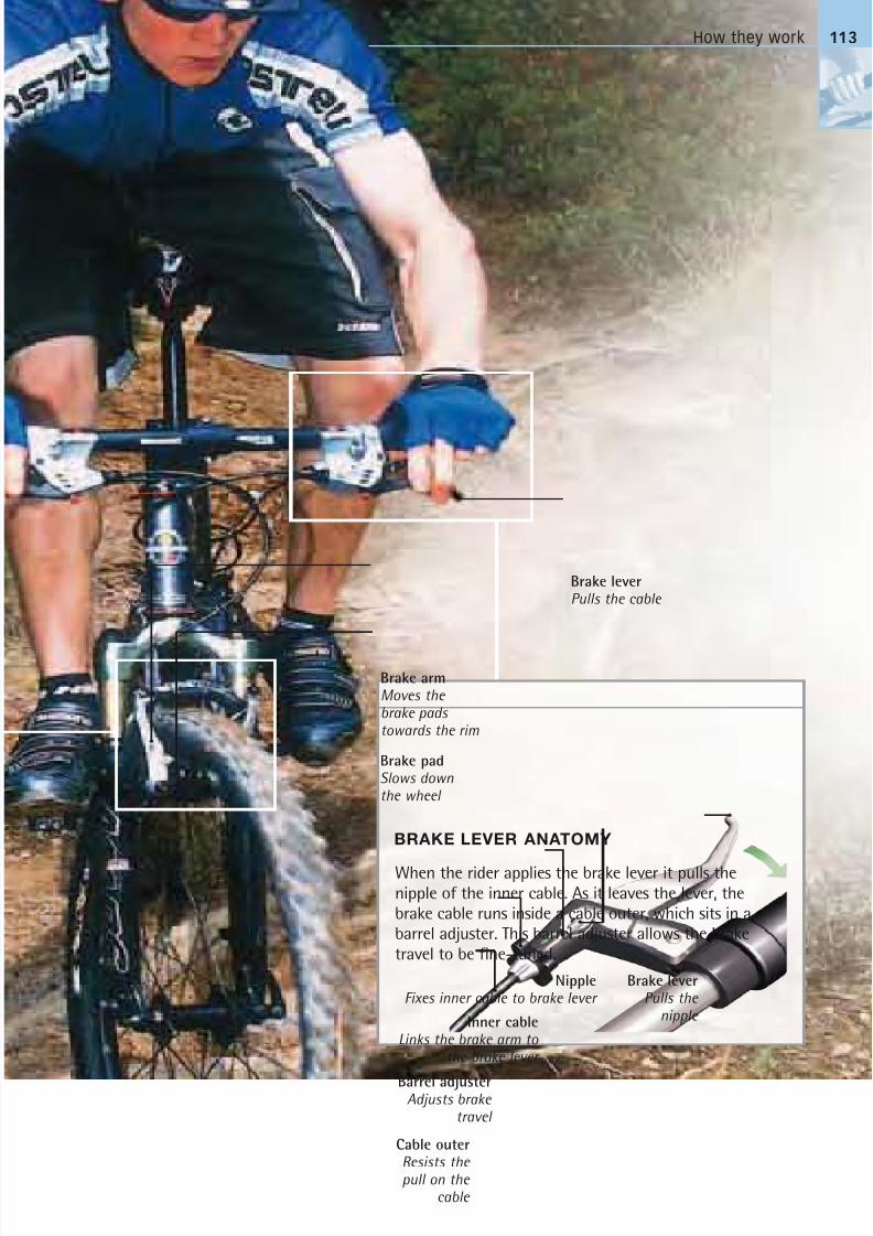
8/20/2019 Bike Repair Manual.downarchive
http://slidepdf.com/reader/full/bike-repair-manualdownarchive 113/160
How they work 113
When the rider applies the brake lever it pulls the
nipple of the inner cable. As it leaves the lever, the
brake cable runs inside a cable outer, which sits in a
barrel adjuster. This barrel adjuster allows the brake
travel to be fine-tuned.
Brake leverPulls the cable
Brake armMoves the brake pads towards the rim
Brake padSlows downthe wheel
Brake leverPulls the
nipple
Barrel adjusterAdjusts brake
travel
Inner cableLinks the brake arm to
the brake lever
Cable outerResists the pull on the
cable
NippleFixes inner cable to brake lever
BRAKE LEVER ANATOMY
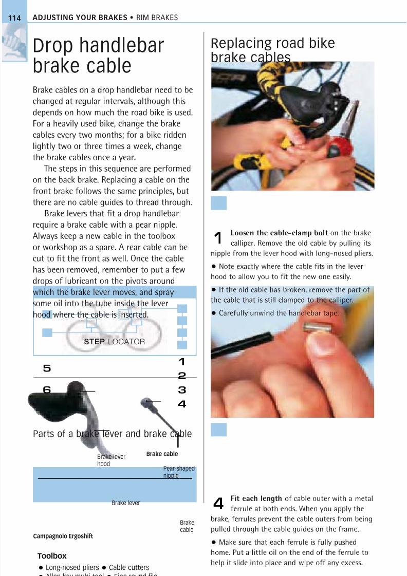
8/20/2019 Bike Repair Manual.downarchive
http://slidepdf.com/reader/full/bike-repair-manualdownarchive 114/160
1
2
3
4
ADJUSTING YOUR BRAKES • RIM BRAKES
Drop handlebarbrake cableBrake cables on a drop handlebar need to be
changed at regular intervals, although thisdepends on how much the road bike is used.
For a heavily used bike, change the brake
cables every two months; for a bike ridden
lightly two or three times a week, change
the brake cables once a year.
The steps in this sequence are performed
on the back brake. Replacing a cable on the
front brake follows the same principles, but
there are no cable guides to thread through.Brake levers that fit a drop handlebar
require a brake cable with a pear nipple.
Always keep a new cable in the toolbox
or workshop as a spare. A rear cable can be
cut to fit the front as well. Once the cable
has been removed, remember to put a few
drops of lubricant on the pivots around
which the brake lever moves, and spray
some oil into the tube inside the leverhood where the cable is inserted.
Replacing road bikebrake cables
Loosen the cable-clamp bolt on the brake
calliper. Remove the old cable by pulling its
nipple from the lever hood with long-nosed pliers.
• Note exactly where the cable fits in the lever
hood to allow you to fit the new one easily.
• If the old cable has broken, remove the part of
the cable that is still clamped to the calliper.• Carefully unwind the handlebar tape.
1
Fit each length of cable outer with a metal
ferrule at both ends. When you apply the
brake, ferrules prevent the cable outers from being
pulled through the cable guides on the frame.
• Make sure that each ferrule is fully pushed
home. Put a little oil on the end of the ferrule to
help it slide into place and wipe off any excess.
4
Toolbox
Long-nosed pliers Cable cutters
Allen key multi-tool Fine round file
Parts of a brake lever and brake cable
Brake cable
6
5
STEP LOCATOR
114
Brake lever
Brake leverhood
Pear-shapednipple
Brakecable
Campagnolo Ergoshift
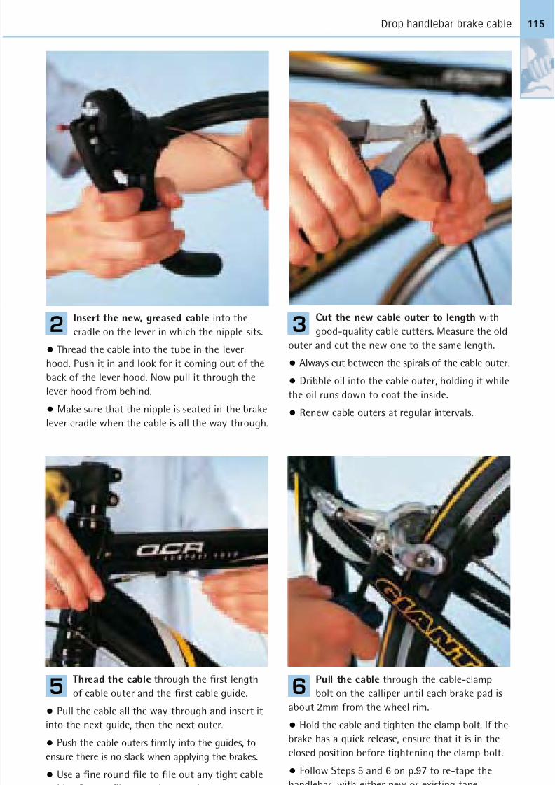
8/20/2019 Bike Repair Manual.downarchive
http://slidepdf.com/reader/full/bike-repair-manualdownarchive 115/160
Drop handlebar brake cable
Insert the new, greased cable into the
cradle on the lever in which the nipple sits.
• Thread the cable into the tube in the lever
hood. Push it in and look for it coming out of the
back of the lever hood. Now pull it through the
lever hood from behind.
• Make sure that the nipple is seated in the brakelever cradle when the cable is all the way through.
2
Thread the cable through the first length
of cable outer and the first cable guide.
• Pull the cable all the way through and insert it
into the next guide, then the next outer.
• Push the cable outers firmly into the guides, to
ensure there is no slack when applying the brakes.
• Use a fine round file to file out any tight cable
guides. Do not file more than you have to.
5
Pull the cable through the cable-clamp
bolt on the calliper until each brake pad is
about 2mm from the wheel rim.
• Hold the cable and tighten the clamp bolt. If the
brake has a quick release, ensure that it is in the
closed position before tightening the clamp bolt.
• Follow Steps 5 and 6 on p.97 to re-tape the
handlebar, with either new or existing tape.
6
Cut the new cable outer to length with
good-quality cable cutters. Measure the old
outer and cut the new one to the same length.
• Always cut between the spirals of the cable outer.
• Dribble oil into the cable outer, holding it while
the oil runs down to coat the inside.
• Renew cable outers at regular intervals.
3
115
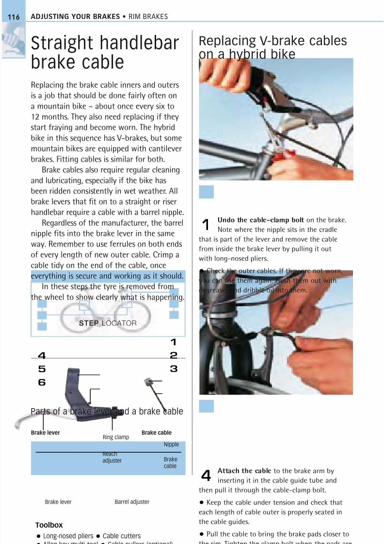
8/20/2019 Bike Repair Manual.downarchive
http://slidepdf.com/reader/full/bike-repair-manualdownarchive 116/160
4
5
6
ADJUSTING YOUR BRAKES • RIM BRAKES
Straight handlebarbrake cableReplacing the brake cable inners and outers
is a job that should be done fairly often ona mountain bike – about once every six to
12 months. They also need replacing if they
start fraying and become worn. The hybrid
bike in this sequence has V-brakes, but some
mountain bikes are equipped with cantilever
brakes. Fitting cables is similar for both.
Brake cables also require regular cleaning
and lubricating, especially if the bike has
been ridden consistently in wet weather. Allbrake levers that fit on to a straight or riser
handlebar require a cable with a barrel nipple.
Regardless of the manufacturer, the barrel
nipple fits into the brake lever in the same
way. Remember to use ferrules on both ends
of every length of new outer cable. Crimp a
cable tidy on the end of the cable, once
everything is secure and working as it should.
In these steps the tyre is removed fromthe wheel to show clearly what is happening.
Replacing V-brake cableson a hybrid bike
Undo the cable-clamp bolt on the brake.
Note where the nipple sits in the cradle
that is part of the lever and remove the cable
from inside the brake lever by pulling it out
with long-nosed pliers.
• Check the outer cables. If they are not worn,
you can use them again. Flush them out with
degreaser and dribble oil into them.
1
Attach the cable to the brake arm by
inserting it in the cable guide tube and
then pull it through the cable-clamp bolt.
• Keep the cable under tension and check that
each length of cable outer is properly seated in
the cable guides.
• Pull the cable to bring the brake pads closer to
the rim. Tighten the clamp bolt when the pads are
about 2mm from the rim.
4
Toolbox
Long-nosed pliers Cable cutters
Allen key multi-tool Cable pullers (optional)
Parts of a brake lever and a brake cable
Brake cable
116
Brake lever Barrel adjuster
Reachadjuster
STEP LOCATOR
1
2
3
Nipple
Brakecable
Ring clampBrake lever
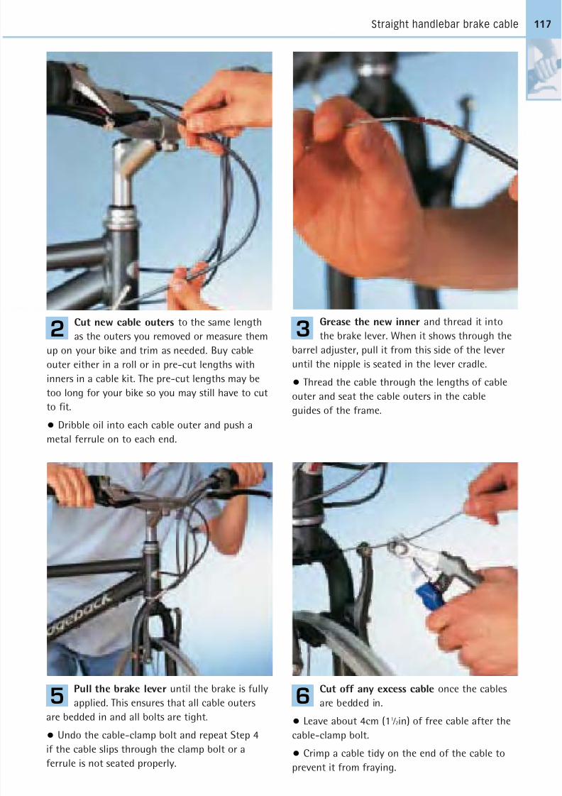
8/20/2019 Bike Repair Manual.downarchive
http://slidepdf.com/reader/full/bike-repair-manualdownarchive 117/160
Straight handlebar brake cable
Cut new cable outers to the same length
as the outers you removed or measure them
up on your bike and trim as needed. Buy cable
outer either in a roll or in pre-cut lengths with
inners in a cable kit. The pre-cut lengths may be
too long for your bike so you may still have to cut
to fit.
• Dribble oil into each cable outer and push a
metal ferrule on to each end.
2
Pull the brake lever until the brake is fully
applied. This ensures that all cable outers
are bedded in and all bolts are tight.
• Undo the cable-clamp bolt and repeat Step 4
if the cable slips through the clamp bolt or a
ferrule is not seated properly.
5
Cut off any excess cable once the cables
are bedded in.
• Leave about 4cm (11 ⁄ 2in) of free cable after the
cable-clamp bolt.
• Crimp a cable tidy on the end of the cable to
prevent it from fraying.
6
Grease the new inner and thread it into
the brake lever. When it shows through the
barrel adjuster, pull it from this side of the lever
until the nipple is seated in the lever cradle.
• Thread the cable through the lengths of cable
outer and seat the cable outers in the cable
guides of the frame.
3
117

8/20/2019 Bike Repair Manual.downarchive
http://slidepdf.com/reader/full/bike-repair-manualdownarchive 118/160
STEP LOCATOR
ADJUSTING YOUR BRAKES • RIM BRAKES118
Calliper brakeMaintaining calliper brakes is a question of regularly checking the action of the brakelever. If you have to pull it too far before the
brake bites, the brake needs adjusting. Checkthe brake pads for wear and alignment, andensure that they contact the braking surfaceof the rims simultaneously.
How far the lever has to be pulled beforethe brake comes on depends on the rider.People with smaller hands may prefer moretravel in the lever before the brake bites,because they will pull with more strength
the closer the lever is to the handlebar.Apart from their quick releases, all dual-
pivot calliper brakes (such as the Shimanobrakes shown here) work in the same way,regardless of the manufacturer. This meansthat you should be able to apply these stepsto your bike, whatever its brakes.
Adjusting a calliper brake
Periodically check for pad wear. If the
pads are wearing down towards half their
original depth they must be replaced.
• Undo the Allen key pad retainer and push out
the pad. If the pad and shoe are a complete piece,
replace the whole unit, releasing the old pad and
fitting the new one with a 5mm Allen key.
1
Pull the brake on with the brake lever and
check to see if both pads simultaneously
come into contact with the braking surface on
the rim of the wheel.
• Make sure that both sides are working together
by turning an adjustment screw on the side of the
calliper with an Allen key. This process is called
“centring” the brakes.
3
Toolbox
Full set of Allen keys or Allen key multi-tool
Long-nosed pliers (optional)
Parts of a calliper brake
1 2 3 4
Calliper arm
Centre-fixing bolt
Centringadjustingscrew
Brake shoebolt
Brake shoe
Brake pad
Traveladjuster,
spring,and
washer
1
1
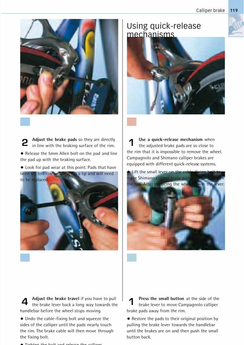
8/20/2019 Bike Repair Manual.downarchive
http://slidepdf.com/reader/full/bike-repair-manualdownarchive 119/160
Calliper brake 119
Adjust the brake pads so they are directly
in line with the braking surface of the rim.
• Release the 5mm Allen bolt on the pad and line
the pad up with the braking surface.
• Look for pad wear at this point. Pads that have
been set too low will develop a lip and will need
to be replaced.
2
Adjust the brake travel if you have to pull
the brake lever back a long way towards the
handlebar before the wheel stops moving.
• Undo the cable-fixing bolt and squeeze the
sides of the calliper until the pads nearly touch
the rim. The brake cable will then move through
the fixing bolt.
• Tighten the bolt and release the calliper.
4
Press the small button at the side of the
brake lever to move Campagnolo calliper
brake pads away from the rim.
• Restore the pads to their original position by
pulling the brake lever towards the handlebar
until the brakes are on and then push the small
button back.
Use a quick-release mechanism when
the adjusted brake pads are so close to
the rim that it is impossible to remove the wheel.
Campagnolo and Shimano calliper brakes are
equipped with different quick-release systems.
• Lift the small lever on the cable-fixing bolt to
make Shimano calliper brake pads move away from
the rim. After replacing the wheel, lower the lever.
Using quick-releasemechanisms
1
1
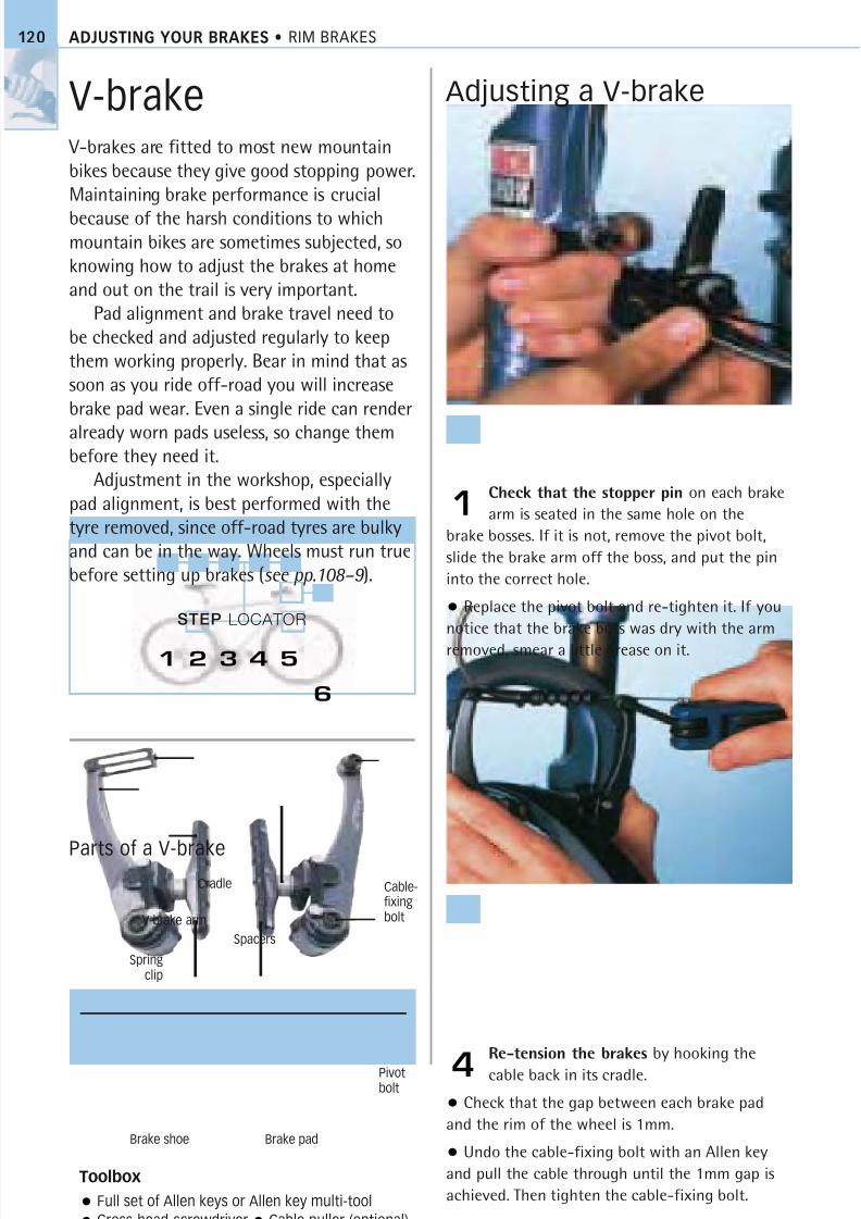
8/20/2019 Bike Repair Manual.downarchive
http://slidepdf.com/reader/full/bike-repair-manualdownarchive 120/160
STEP LOCATOR
ADJUSTING YOUR BRAKES • RIM BRAKES120
V-brake V-brakes are fitted to most new mountainbikes because they give good stopping power.Maintaining brake performance is crucial
because of the harsh conditions to whichmountain bikes are sometimes subjected, soknowing how to adjust the brakes at homeand out on the trail is very important.
Pad alignment and brake travel need tobe checked and adjusted regularly to keepthem working properly. Bear in mind that assoon as you ride off-road you will increasebrake pad wear. Even a single ride can render
already worn pads useless, so change thembefore they need it.
Adjustment in the workshop, especiallypad alignment, is best performed with thetyre removed, since off-road tyres are bulkyand can be in the way. Wheels must run truebefore setting up brakes (see pp.108–9 ).
Adjusting a V-brake
Check that the stopper pin on each brake
arm is seated in the same hole on the
brake bosses. If it is not, remove the pivot bolt,
slide the brake arm off the boss, and put the pin
into the correct hole.
• Replace the pivot bolt and re-tighten it. If you
notice that the brake boss was dry with the arm
removed, smear a little grease on it.
1
Re-tension the brakes by hooking the
cable back in its cradle.
• Check that the gap between each brake pad
and the rim of the wheel is 1mm.
• Undo the cable-fixing bolt with an Allen key
and pull the cable through until the 1mm gap is
achieved. Then tighten the cable-fixing bolt.
4
Toolbox
Full set of Allen keys or Allen key multi-tool
Cross-head screwdriver Cable puller (optional)
1 2 3 4 5
6
Brake padBrake shoe
Cable-fixingbolt
Spacers
V-brake arm
Cradle
Springclip
Pivotbolt
Parts of a V-brake
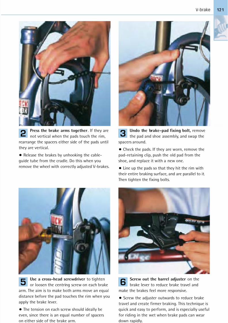
8/20/2019 Bike Repair Manual.downarchive
http://slidepdf.com/reader/full/bike-repair-manualdownarchive 121/160
V-brake
Press the brake arms together. If they are
not vertical when the pads touch the rim,
rearrange the spacers either side of the pads until
they are vertical.
• Release the brakes by unhooking the cable-
guide tube from the cradle. Do this when you
remove the wheel with correctly adjusted V-brakes.
2
Use a cross-head screwdriver to tighten
or loosen the centring screw on each brake
arm. The aim is to make both arms move an equal
distance before the pad touches the rim when you
apply the brake lever.
• The tension on each screw should ideally be
even, since there is an equal number of spacers
on either side of the brake arm.
5
Screw out the barrel adjuster on the
brake lever to reduce brake travel and
make the brakes feel more responsive.
• Screw the adjuster outwards to reduce brake
travel and create firmer braking. This technique is
quick and easy to perform, and is especially useful
for riding in the wet when brake pads can wear
down rapidly.
6
Undo the brake-pad fixing bolt, remove
the pad and shoe assembly, and swap the
spacers around.
• Check the pads. If they are worn, remove the
pad-retaining clip, push the old pad from the
shoe, and replace it with a new one.
• Line up the pads so that they hit the rim withtheir entire braking surface, and are parallel to it.
Then tighten the fixing bolts.
3
121
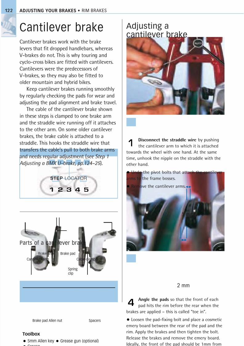
8/20/2019 Bike Repair Manual.downarchive
http://slidepdf.com/reader/full/bike-repair-manualdownarchive 122/160
STEP LOCATOR
ADJUSTING YOUR BRAKES • RIM BRAKES122
Cantilever brakeCantilever brakes work with the brakelevers that fit dropped handlebars, whereas
V-brakes do not. This is why touring and
cyclo-cross bikes are fitted with cantilevers.Cantilevers were the predecessors of
V-brakes, so they may also be fitted toolder mountain and hybrid bikes.
Keep cantilever brakes running smoothlyby regularly checking the pads for wear andadjusting the pad alignment and brake travel.
The cable of the cantilever brake shownin these steps is clamped to one brake arm
and the straddle wire running off it attachesto the other arm. On some older cantileverbrakes, the brake cable is attached to astraddle. This hooks the straddle wire thattransfers the cable’s pull to both brake armsand needs regular adjustment (see Step 1
Adjusting a BMX U-brake, pp.124–25 ).
Adjusting acantilever brake
Disconnect the straddle wire by pushing
the cantilever arm to which it is attached
towards the wheel with one hand. At the same
time, unhook the nipple on the straddle with the
other hand.
• Undo the pivot bolts that attach the cantilever
arms to the frame bosses.
• Remove the cantilever arms.
1
Angle the pads so that the front of each
pad hits the rim before the rear when the
brakes are applied – this is called “toe in”.
• Loosen the pad-fixing bolt and place a cosmetic
emery board between the rear of the pad and the
rim. Apply the brakes and then tighten the bolt.
Release the brakes and remove the emery board.
Ideally, the front of the pad should be 1mm from
the rim and the rear 2mm.
4
Toolbox
5mm Allen key Grease gun (optional)
Grease
Parts of a cantilever brake
1 2 3 4 5
Cantilever arm
SpacersBrake pad Allen nut
Brake padBrake shoe
Cable-clamp bolt
1 mm
2 mm
Springclip

8/20/2019 Bike Repair Manual.downarchive
http://slidepdf.com/reader/full/bike-repair-manualdownarchive 123/160
Cantilever brake 123
Clean the exposed frame bosses with a
cloth soaked in degreaser, then lubricate
with a light grease, not a heavy-duty industrial
grease. Use a grease gun if you have one.
• Bolt both arms back on to the bosses, making
sure that the stopper pins are inserted into the
same hole on each boss.
• Replace the pivot bolts and then tighten them
to hold the brake arms to the bosses.
2
Undo the brake-cable
clamp to achieve the
proper spacing from the pad
to the rim.
• Pull the cable through the
clamp until the front of each
brake pad is 1mm from therim. Tighten the clamp bolt.
• Pull the brake lever to see
if both brake arms contact
the rim simultaneously. If they
do not, screw the centring
screws in or out on each arm
until they do.
5
Check the pads. If one is worn or badly
aligned, undo the pad-fixing bolt with an
Allen key and remove the pad/shoe assembly.
• Remove the spring clip from the brake shoe and
slide out the worn pad. Slide in a new pad and
replace the spring clip.
• Return the assembly to the brake arm, line upthe pad so that its entire surface contacts the rim,
and is parallel with it, then tighten the bolt.
3
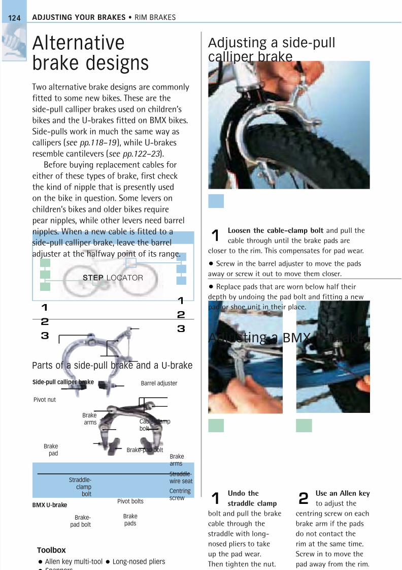
8/20/2019 Bike Repair Manual.downarchive
http://slidepdf.com/reader/full/bike-repair-manualdownarchive 124/160
Use an Allen key
to adjust the
centring screw on each
brake arm if the pads
do not contact the
rim at the same time.
Screw in to move the
pad away from the rim.
STEP LOCATOR
1
2
3
ADJUSTING YOUR BRAKES • RIM BRAKES
Alternativebrake designsTwo alternative brake designs are commonly
fitted to some new bikes. These are theside-pull calliper brakes used on children’sbikes and the U-brakes fitted on BMX bikes.Side-pulls work in much the same way ascallipers (see pp.118–19 ), while U-brakesresemble cantilevers (see pp.122–23 ).
Before buying replacement cables foreither of these types of brake, first checkthe kind of nipple that is presently used
on the bike in question. Some levers onchildren’s bikes and older bikes requirepear nipples, while other levers need barrelnipples. When a new cable is fitted to aside-pull calliper brake, leave the barreladjuster at the halfway point of its range.
Adjusting a side-pullcalliper brake
Loosen the cable-clamp bolt and pull the
cable through until the brake pads are
closer to the rim. This compensates for pad wear.
• Screw in the barrel adjuster to move the pads
away or screw it out to move them closer.
• Replace pads that are worn below half their
depth by undoing the pad bolt and fitting a newpad or shoe unit in their place.
1
Undo the
straddle clamp
bolt and pull the brake
cable through the
straddle with long-
nosed pliers to take
up the pad wear.
Then tighten the nut.
1 2
Toolbox
Allen key multi-tool Long-nosed pliers
Spanners
Parts of a side-pull brake and a U-brake
Brakearms
Centring
screw
Straddle-wire seat
1
2
3
124
Pivot bolts
Brakepads
Straddle-clamp
bolt
Adjusting a BMX U-brake
Pivot nut
Brakepad
Brake-pad bolt
Barrel adjuster
Cable-clampbolt
Brakearms
BMX U-brake
Side-pull calliper brake
Brake-pad bolt
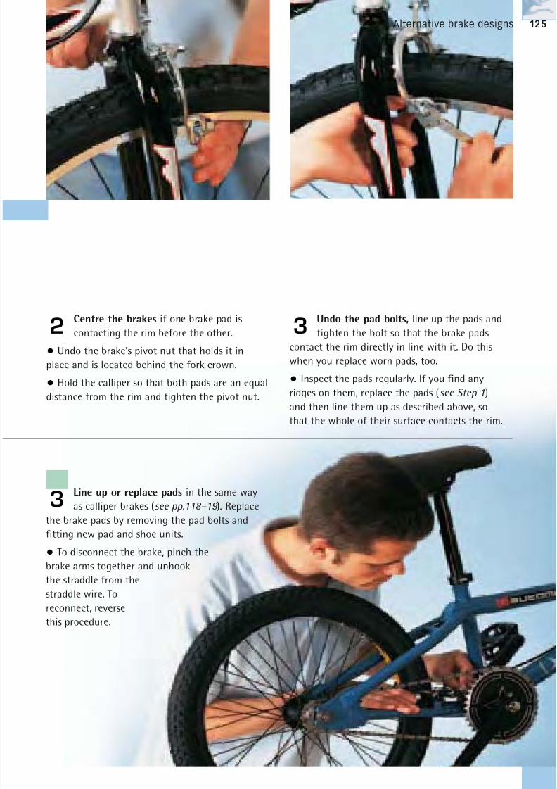
8/20/2019 Bike Repair Manual.downarchive
http://slidepdf.com/reader/full/bike-repair-manualdownarchive 125/160
Alternative brake designs
Centre the brakes if one brake pad is
contacting the rim before the other.
• Undo the brake’s pivot nut that holds it in
place and is located behind the fork crown.
• Hold the calliper so that both pads are an equal
distance from the rim and tighten the pivot nut.
2Undo the pad bolts, line up the pads and
tighten the bolt so that the brake pads
contact the rim directly in line with it. Do this
when you replace worn pads, too.
• Inspect the pads regularly. If you find any
ridges on them, replace the pads (see Step 1)
and then line them up as described above, so
that the whole of their surface contacts the rim.
3
125
Line up or replace pads in the same way
as calliper brakes (see pp.118–19 ). Replace
the brake pads by removing the pad bolts and
fitting new pad and shoe units.
• To disconnect the brake, pinch thebrake arms together and unhook
the straddle from the
straddle wire. To
reconnect, reverse
this procedure.
3
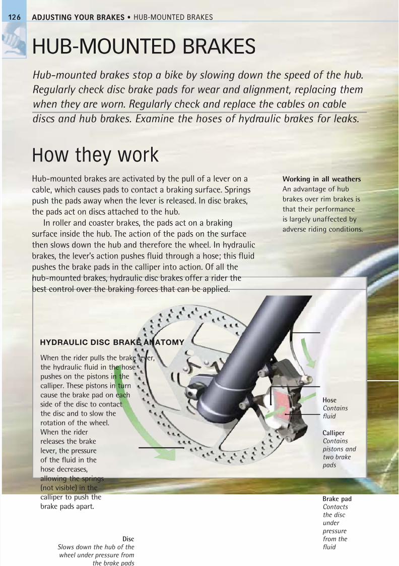
8/20/2019 Bike Repair Manual.downarchive
http://slidepdf.com/reader/full/bike-repair-manualdownarchive 126/160
ADJUSTING YOUR BRAKES • HUB-MOUNTED BRAKES126
HUB-MOUNTED BRAKES
Hub-mounted brakes stop a bike by slowing down the speed of the hub.
Regularly check disc brake pads for wear and alignment, replacing them
when they are worn. Regularly check and replace the cables on cable
discs and hub brakes. Examine the hoses of hydraulic brakes for leaks.
How they workHub-mounted brakes are activated by the pull of a lever on a
cable, which causes pads to contact a braking surface. Springs
push the pads away when the lever is released. In disc brakes,the pads act on discs attached to the hub.
In roller and coaster brakes, the pads act on a braking
surface inside the hub. The action of the pads on the surface
then slows down the hub and therefore the wheel. In hydraulic
brakes, the lever’s action pushes fluid through a hose; this fluid
pushes the brake pads in the calliper into action. Of all the
hub-mounted brakes, hydraulic disc brakes offer a rider the
best control over the braking forces that can be applied.
Working in all weathers
An advantage of hub
brakes over rim brakes isthat their performance
is largely unaffected by
adverse riding conditions.
When the rider pulls the brake lever,the hydraulic fluid in the hosepushes on the pistons in thecalliper. These pistons in turn
cause the brake pad on eachside of the disc to contactthe disc and to slow therotation of the wheel.When the riderreleases the brakelever, the pressureof the fluid in thehose decreases,allowing the springs(not visible) in the
calliper to push thebrake pads apart.
DiscSlows down the hub of the wheel under pressure from
the brake pads
CalliperContains pistons and two brake pads
Brake padContacts the disc under
pressure from the fluid
HoseContains fluid
HYDRAULIC DISC BRAKE ANATOMY
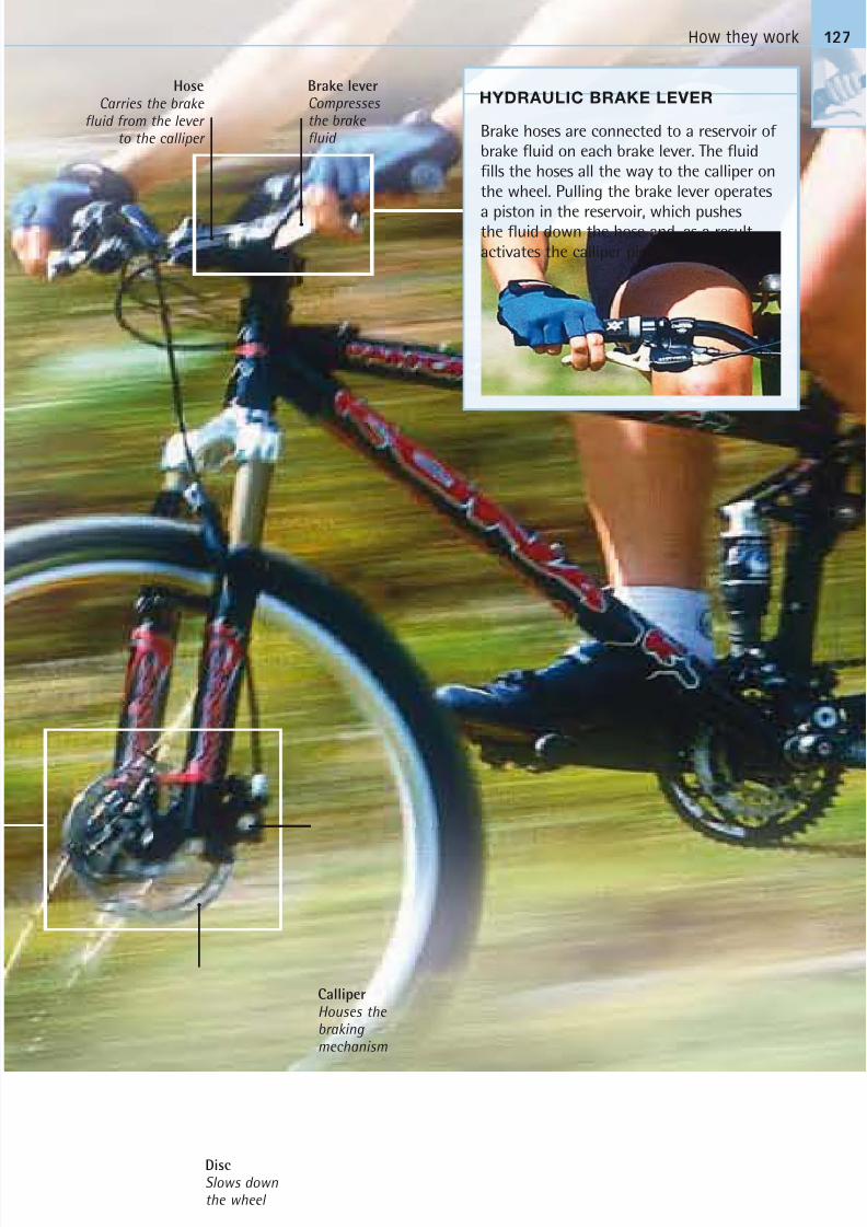
8/20/2019 Bike Repair Manual.downarchive
http://slidepdf.com/reader/full/bike-repair-manualdownarchive 127/160
How they work
HYDRAULIC BRAKE LEVER
Brake hoses are connected to a reservoir of
brake fluid on each brake lever. The fluid
fills the hoses all the way to the calliper on
the wheel. Pulling the brake lever operates
a piston in the reservoir, which pushesthe fluid down the hose and, as a result,
activates the calliper pistons.
Calliper
Houses the braking mechanism
DiscSlows downthe wheel
Brake leverCompresses the brake fluid
Hose
Carries the brake fluid from the lever
to the calliper
127
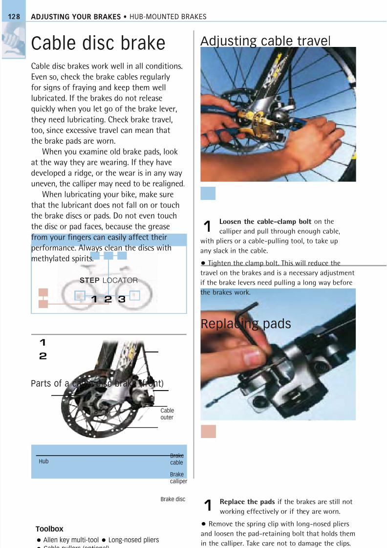
8/20/2019 Bike Repair Manual.downarchive
http://slidepdf.com/reader/full/bike-repair-manualdownarchive 128/160
STEP LOCATOR
1
2
ADJUSTING YOUR BRAKES • HUB-MOUNTED BRAKES128
Cable disc brakeCable disc brakes work well in all conditions.
Even so, check the brake cables regularly
for signs of fraying and keep them well
lubricated. If the brakes do not releasequickly when you let go of the brake lever,
they need lubricating. Check brake travel,
too, since excessive travel can mean that
the brake pads are worn.
When you examine old brake pads, look
at the way they are wearing. If they have
developed a ridge, or the wear is in any way
uneven, the calliper may need to be realigned.
When lubricating your bike, make surethat the lubricant does not fall on or touch
the brake discs or pads. Do not even touch
the disc or pad faces, because the grease
from your fingers can easily affect their
performance. Always clean the discs with
methylated spirits.
Adjusting cable travel
Loosen the cable-clamp bolt on the
calliper and pull through enough cable,
with pliers or a cable-pulling tool, to take up
any slack in the cable.
• Tighten the clamp bolt. This will reduce the
travel on the brakes and is a necessary adjustment
if the brake levers need pulling a long way before
the brakes work.
1
Replace the pads if the brakes are still not
working effectively or if they are worn.
• Remove the spring clip with long-nosed pliers
and loosen the pad-retaining bolt that holds them
in the calliper. Take care not to damage the clips.
The pads should now drop out.
1
Toolbox
Allen key multi-tool Long-nosed pliers
Cable pullers (optional)
Parts of a cable disc brake (front)
1 2 3
Replacing pads
Cableouter
Brakecable
Brake
calliper
Brake disc
Hub
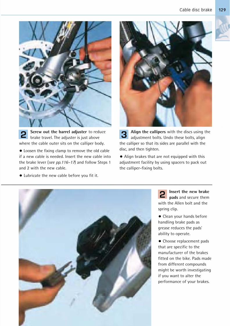
8/20/2019 Bike Repair Manual.downarchive
http://slidepdf.com/reader/full/bike-repair-manualdownarchive 129/160
Cable disc brake 129
Screw out the barrel adjuster to reduce
brake travel. The adjuster is just above
where the cable outer sits on the calliper body.
• Loosen the fixing clamp to remove the old cable
if a new cable is needed. Insert the new cable into
the brake lever (see pp.116–17 ) and follow Steps 1
and 2 with the new cable.
• Lubricate the new cable before you fit it.
2
Insert the new brake
pads and secure them
with the Allen bolt and the
spring clip.
• Clean your hands before
handling brake pads as
grease reduces the pads’ability to operate.
• Choose replacement pads
that are specific to the
manufacturer of the brakes
fitted on the bike. Pads made
from different compounds
might be worth investigating
if you want to alter the
performance of your brakes.
2
Align the callipers with the discs using the
adjustment bolts. Undo these bolts, align
the calliper so that its sides are parallel with the
disc, and then tighten.
• Align brakes that are not equipped with this
adjustment facility by using spacers to pack out
the calliper-fixing bolts.
3
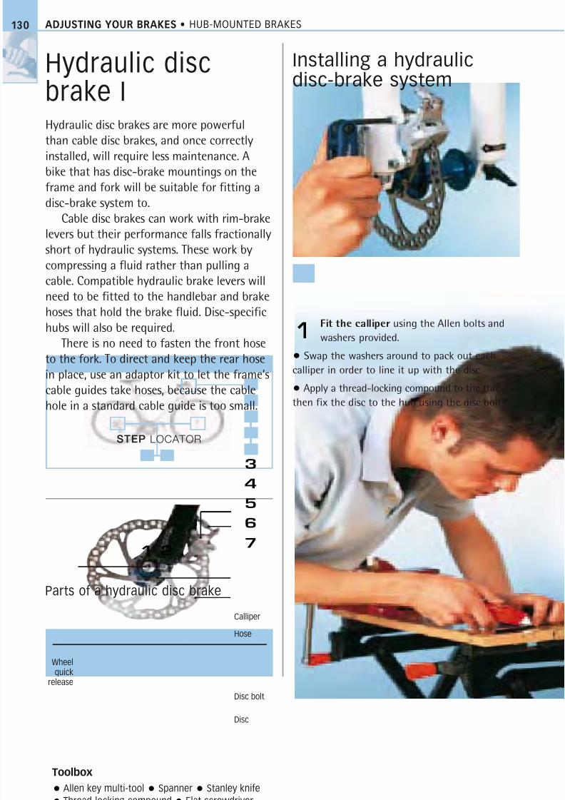
8/20/2019 Bike Repair Manual.downarchive
http://slidepdf.com/reader/full/bike-repair-manualdownarchive 130/160
STEP LOCATOR
ADJUSTING YOUR BRAKES • HUB-MOUNTED BRAKES
Hydraulic discbrake IHydraulic disc brakes are more powerful
than cable disc brakes, and once correctlyinstalled, will require less maintenance. A
bike that has disc-brake mountings on the
frame and fork will be suitable for fitting a
disc-brake system to.
Cable disc brakes can work with rim-brake
levers but their performance falls fractionally
short of hydraulic systems. These work by
compressing a fluid rather than pulling a
cable. Compatible hydraulic brake levers willneed to be fitted to the handlebar and brake
hoses that hold the brake fluid. Disc-specific
hubs will also be required.
There is no need to fasten the front hose
to the fork. To direct and keep the rear hose
in place, use an adaptor kit to let the frame’s
cable guides take hoses, because the cable
hole in a standard cable guide is too small.
Installing a hydraulicdisc-brake system
Fit the calliper using the Allen bolts and
washers provided.
• Swap the washers around to pack out each
calliper in order to line it up with the disc.
• Apply a thread-locking compound to the threads,
then fix the disc to the hub using the disc bolts.
1
Toolbox
Allen key multi-tool Spanner Stanley knife
Thread-locking compound Flat screwdriver
Parts of a hydraulic disc brake
3
4
5
6
71 2
130
Calliper
Disc
Wheelquick
release
Hose
Disc bolt
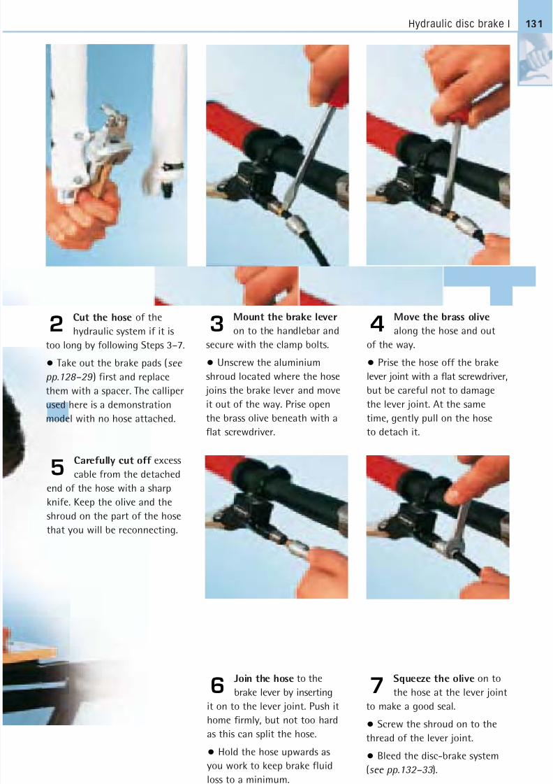
8/20/2019 Bike Repair Manual.downarchive
http://slidepdf.com/reader/full/bike-repair-manualdownarchive 131/160
Hydraulic disc brake I
Cut the hose of the
hydraulic system if it is
too long by following Steps 3–7.
• Take out the brake pads (see
pp.128–29 ) first and replace
them with a spacer. The calliper
used here is a demonstration
model with no hose attached.
2
Carefully cut off excess
cable from the detached
end of the hose with a sharp
knife. Keep the olive and the
shroud on the part of the hose
that you will be reconnecting.
5
Join the hose to the
brake lever by inserting
it on to the lever joint. Push it
home firmly, but not too hard
as this can split the hose.
• Hold the hose upwards as
you work to keep brake fluid
loss to a minimum.
6
Squeeze the olive on to
the hose at the lever joint
to make a good seal.
• Screw the shroud on to the
thread of the lever joint.
• Bleed the disc-brake system
(see pp.132–33 ).
7
Move the brass olive
along the hose and out
of the way.
• Prise the hose off the brake
lever joint with a flat screwdriver,
but be careful not to damage
the lever joint. At the same
time, gently pull on the hose
to detach it.
4Mount the brake lever
on to the handlebar and
secure with the clamp bolts.
• Unscrew the aluminium
shroud located where the hose
joins the brake lever and move
it out of the way. Prise open
the brass olive beneath with a
flat screwdriver.
3
131
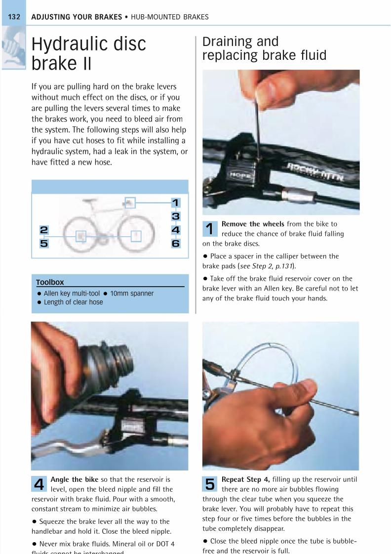
8/20/2019 Bike Repair Manual.downarchive
http://slidepdf.com/reader/full/bike-repair-manualdownarchive 132/160
132
Draining andreplacing brake fluid
Remove the wheels from the bike to
reduce the chance of brake fluid falling
on the brake discs.
• Place a spacer in the calliper between the
brake pads (see Step 2, p.131).
• Take off the brake fluid reservoir cover on the
brake lever with an Allen key. Be careful not to letany of the brake fluid touch your hands.
1
Repeat Step 4, filling up the reservoir until
there are no more air bubbles flowing
through the clear tube when you squeeze the
brake lever. You will probably have to repeat this
step four or five times before the bubbles in the
tube completely disappear.
• Close the bleed nipple once the tube is bubble-
free and the reservoir is full.
5
Angle the bike so that the reservoir is
level, open the bleed nipple and fill the
reservoir with brake fluid. Pour with a smooth,
constant stream to minimize air bubbles.
• Squeeze the brake lever all the way to the
handlebar and hold it. Close the bleed nipple.
• Never mix brake fluids. Mineral oil or DOT 4
fluids cannot be interchanged.
4
Toolbox
Allen key multi-tool 10mm spanner
Length of clear hose
2
5
1
3
4
6
Hydraulic discbrake IIIf you are pulling hard on the brake levers
without much effect on the discs, or if youare pulling the levers several times to make
the brakes work, you need to bleed air from
the system. The following steps will also help
if you have cut hoses to fit while installing a
hydraulic system, had a leak in the system, or
have fitted a new hose.
ADJUSTING YOUR BRAKES • HUB-MOUNTED BRAKES
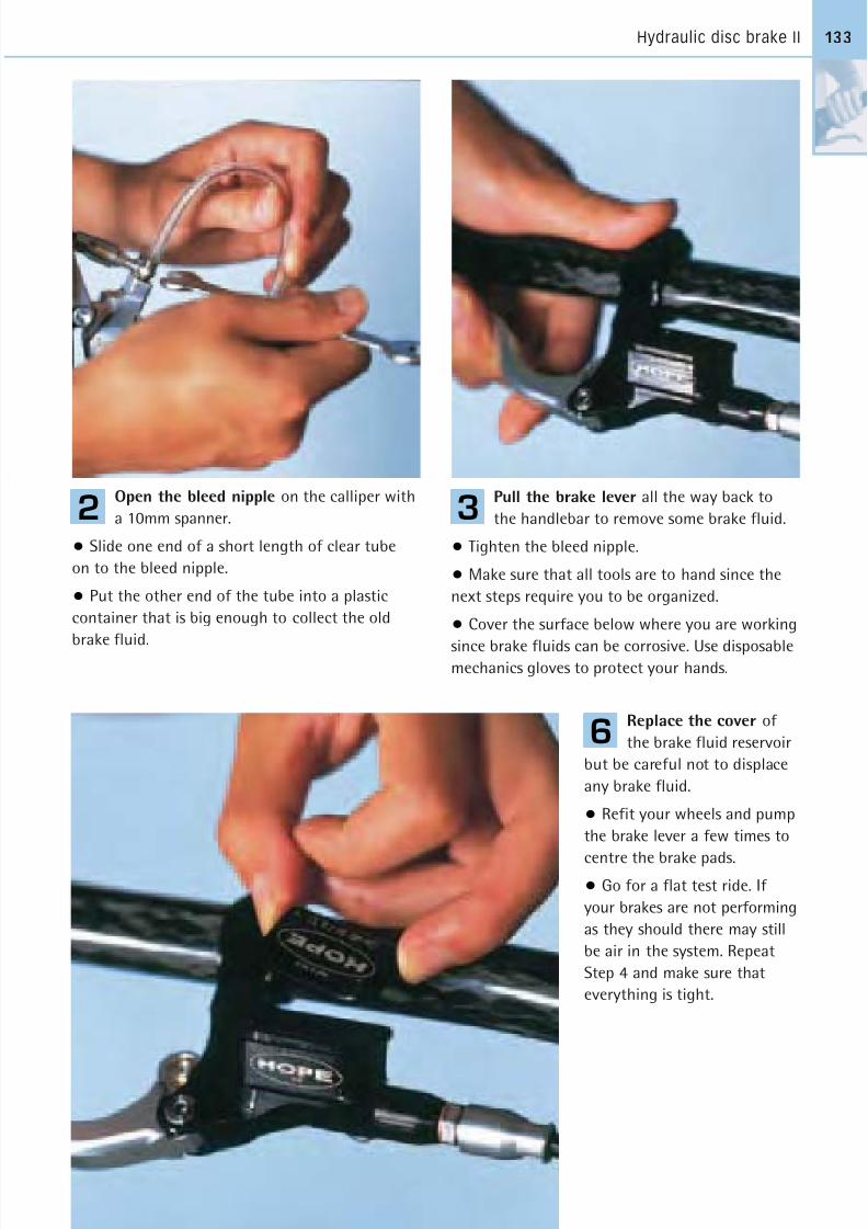
8/20/2019 Bike Repair Manual.downarchive
http://slidepdf.com/reader/full/bike-repair-manualdownarchive 133/160
Hydraulic disc brake II 133
Open the bleed nipple on the calliper with
a 10mm spanner.
• Slide one end of a short length of clear tube
on to the bleed nipple.
• Put the other end of the tube into a plastic
container that is big enough to collect the old
brake fluid.
2
Replace the cover of
the brake fluid reservoir
but be careful not to displace
any brake fluid.
• Refit your wheels and pump
the brake lever a few times to
centre the brake pads.
• Go for a flat test ride. If
your brakes are not performing
as they should there may still
be air in the system. Repeat
Step 4 and make sure that
everything is tight.
6
Pull the brake lever all the way back to
the handlebar to remove some brake fluid.
• Tighten the bleed nipple.
• Make sure that all tools are to hand since the
next steps require you to be organized.
• Cover the surface below where you are working
since brake fluids can be corrosive. Use disposablemechanics gloves to protect your hands.
3
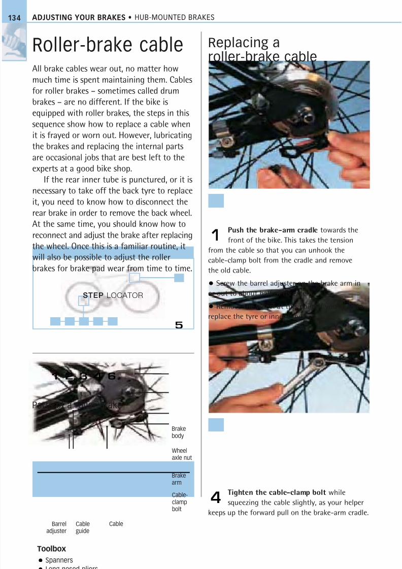
8/20/2019 Bike Repair Manual.downarchive
http://slidepdf.com/reader/full/bike-repair-manualdownarchive 134/160
ADJUSTING YOUR BRAKES • HUB-MOUNTED BRAKES
Roller-brake cableAll brake cables wear out, no matter how
much time is spent maintaining them. Cables
for roller brakes – sometimes called drum
brakes – are no different. If the bike isequipped with roller brakes, the steps in this
sequence show how to replace a cable when
it is frayed or worn out. However, lubricating
the brakes and replacing the internal parts
are occasional jobs that are best left to the
experts at a good bike shop.
If the rear inner tube is punctured, or it is
necessary to take off the back tyre to replace
it, you need to know how to disconnect therear brake in order to remove the back wheel.
At the same time, you should know how to
reconnect and adjust the brake after replacing
the wheel. Once this is a familiar routine, it
will also be possible to adjust the roller
brakes for brake pad wear from time to time.
Replacing aroller-brake cable
Push the brake-arm cradle towards the
front of the bike. This takes the tension
from the cable so that you can unhook the
cable-clamp bolt from the cradle and remove
the old cable.
• Screw the barrel adjuster on the brake arm in
or out to about half of its extent.
• Remove the wheel at this point if you need to
replace the tyre or inner tube.
1
Tighten the cable-clamp bolt while
squeezing the cable slightly, as your helper
keeps up the forward pull on the brake-arm cradle.4
Toolbox
Spanners
Long-nosed pliers
Parts of a roller brake
Brakebody
Wheelaxle nut
Brakearm
Cable-clampbolt
CableCableguide
Barreladjuster
5
134
STEP LOCATOR
1 2 3 4 6
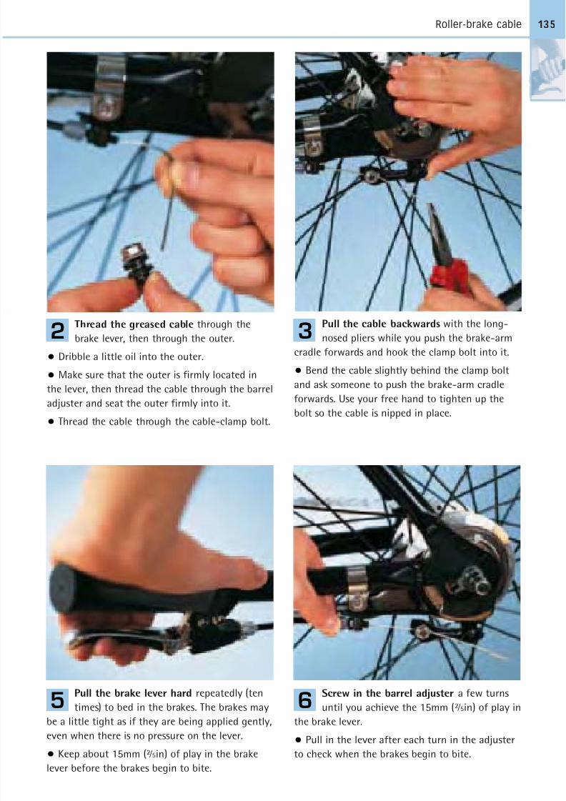
8/20/2019 Bike Repair Manual.downarchive
http://slidepdf.com/reader/full/bike-repair-manualdownarchive 135/160
Roller-brake cable
Thread the greased cable through the
brake lever, then through the outer.
• Dribble a little oil into the outer.
• Make sure that the outer is firmly located in
the lever, then thread the cable through the barrel
adjuster and seat the outer firmly into it.
• Thread the cable through the cable-clamp bolt.
2
Pull the brake lever hard repeatedly (ten
times) to bed in the brakes. The brakes may
be a little tight as if they are being applied gently,
even when there is no pressure on the lever.
• Keep about 15mm (2 ⁄ 5in) of play in the brake
lever before the brakes begin to bite.
5
Screw in the barrel adjuster a few turns
until you achieve the 15mm (2 ⁄ 5in) of play in
the brake lever.
• Pull in the lever after each turn in the adjuster
to check when the brakes begin to bite.
6
Pull the cable backwards with the long-
nosed pliers while you push the brake-arm
cradle forwards and hook the clamp bolt into it.
• Bend the cable slightly behind the clamp bolt
and ask someone to push the brake-arm cradle
forwards. Use your free hand to tighten up the
bolt so the cable is nipped in place.
3
135
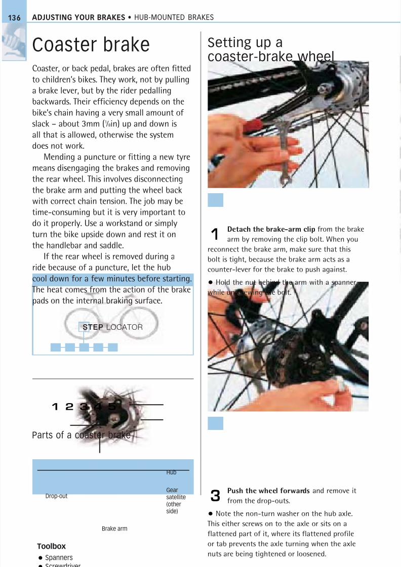
8/20/2019 Bike Repair Manual.downarchive
http://slidepdf.com/reader/full/bike-repair-manualdownarchive 136/160
ADJUSTING YOUR BRAKES • HUB-MOUNTED BRAKES
Coaster brakeCoaster, or back pedal, brakes are often fittedto children’s bikes. They work, not by pullinga brake lever, but by the rider pedalling
backwards. Their efficiency depends on thebike’s chain having a very small amount of slack – about 3mm (1 ⁄ 8in) up and down isall that is allowed, otherwise the systemdoes not work.
Mending a puncture or fitting a new tyremeans disengaging the brakes and removingthe rear wheel. This involves disconnectingthe brake arm and putting the wheel back
with correct chain tension. The job may betime-consuming but it is very important todo it properly. Use a workstand or simplyturn the bike upside down and rest it onthe handlebar and saddle.
If the rear wheel is removed during aride because of a puncture, let the hubcool down for a few minutes before starting.The heat comes from the action of the brake
pads on the internal braking surface.
Detach the brake-arm clip from the brake
arm by removing the clip bolt. When you
reconnect the brake arm, make sure that this
bolt is tight, because the brake arm acts as a
counter-lever for the brake to push against.
• Hold the nut behind the arm with a spanner,
while unscrewing the bolt.
1
Push the wheel forwards and remove it
from the drop-outs.
• Note the non-turn washer on the hub axle.
This either screws on to the axle or sits on a
flattened part of it, where its flattened profile
or tab prevents the axle turning when the axle
nuts are being tightened or loosened.
3
Toolbox
Spanners
Screwdriver
136
STEP LOCATOR
1 2 3 4 5
Setting up acoaster-brake wheel
Parts of a coaster brake
Hub
Gear
satellite(otherside)
Drop-out
Brake arm
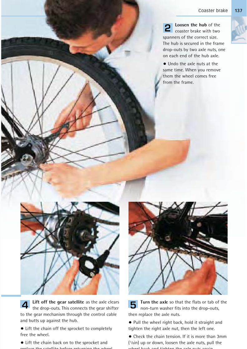
8/20/2019 Bike Repair Manual.downarchive
http://slidepdf.com/reader/full/bike-repair-manualdownarchive 137/160
Coaster brake
Loosen the hub of the
coaster brake with two
spanners of the correct size.
The hub is secured in the frame
drop-outs by two axle nuts, one
on each end of the hub axle.
• Undo the axle nuts at the
same time. When you remove
them the wheel comes free
from the frame.
2
Lift off the gear satellite as the axle clears
the drop-outs. This connects the gear shifter
to the gear mechanism through the control cable
and butts up against the hub.
• Lift the chain off the sprocket to completely
free the wheel.
• Lift the chain back on to the sprocket and
replace the satellite before returning the wheel.
4
Turn the axle so that the flats or tab of the
non-turn washer fits into the drop-outs,
then replace the axle nuts.
• Pull the wheel right back, hold it straight and
tighten the right axle nut, then the left one.
• Check the chain tension. If it is more than 3mm
(1 ⁄ 8in) up or down, loosen the axle nuts, pull the
wheel back and tighten the axle nuts again.
Reconnect the brake arm by reversing Step 1.
5
137
8/20/2019 Bike Repair Manual.downarchive
http://slidepdf.com/reader/full/bike-repair-manualdownarchive 138/160
6
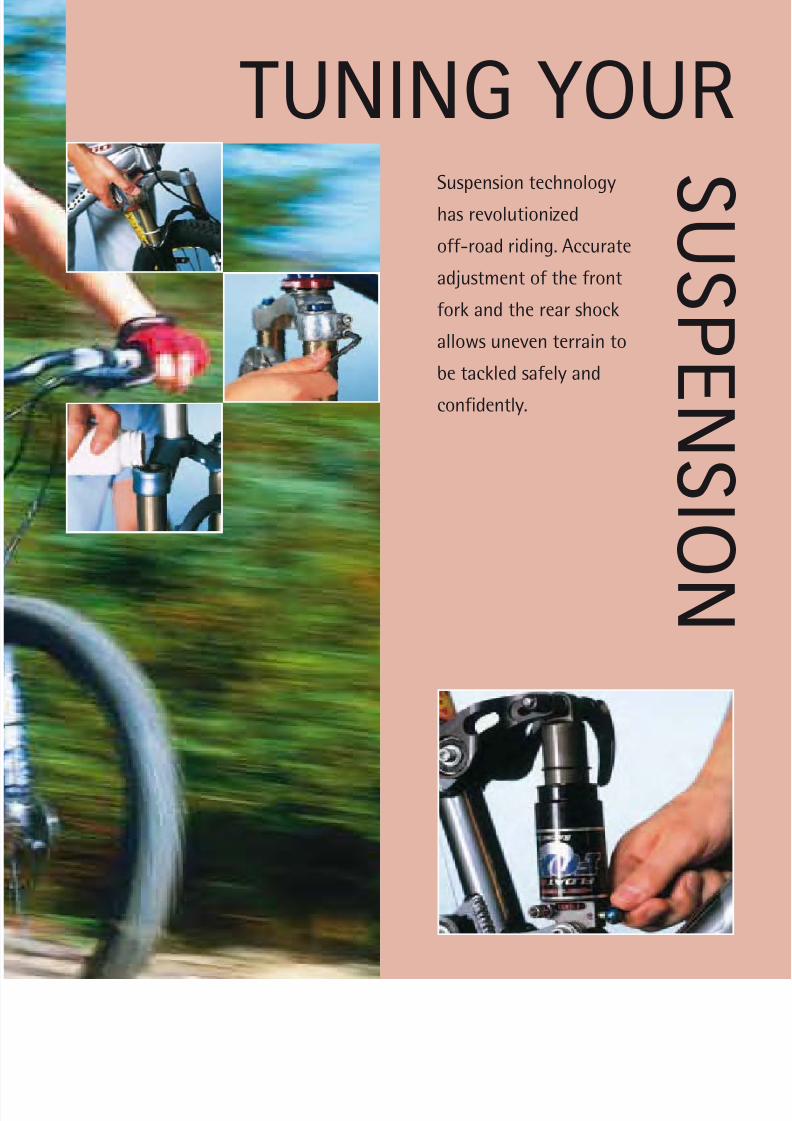
8/20/2019 Bike Repair Manual.downarchive
http://slidepdf.com/reader/full/bike-repair-manualdownarchive 139/160
TUNING YOURSuspension technology
has revolutionized
off-road riding. Accurate
adjustment of the front
fork and the rear shock
allows uneven terrain to
be tackled safely and
confidently.
S U S P
E N S I O
N
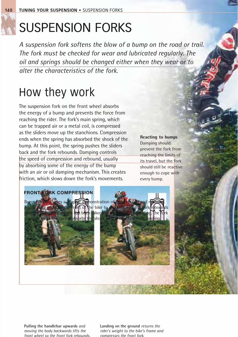
8/20/2019 Bike Repair Manual.downarchive
http://slidepdf.com/reader/full/bike-repair-manualdownarchive 140/160
TUNING YOUR SUSPENSION • SUSPENSION FORKS
SUSPENSION FORKS
A suspension fork softens the blow of a bump on the road or trail.
The fork must be checked for wear and lubricated regularly. The
oil and springs should be changed either when they wear or to
alter the characteristics of the fork.
How they workThe suspension fork on the front wheel absorbs
the energy of a bump and prevents the force from
reaching the rider. The fork’s main spring, whichcan be trapped air or a metal coil, is compressed
as the sliders move up the stanchions. Compression
ends when the spring has absorbed the shock of the
bump. At this point, the spring pushes the sliders
back and the fork rebounds. Damping controls
the speed of compression and rebound, usually
by absorbing some of the energy of the bump
with an air or oil damping mechanism. This creates
friction, which slows down the fork’s movements.
FRONT FORK COMPRESSION
Bunnyhopping gives a graphic demonstration of compression and rebound.
As the rider picks up the front of the bike to clear the log, the fork rebounds
because the rider’s weight has been taken off the spring. On landing, the fork
compresses as the spring absorbs the shock of the bike and rider landing.
Pulling the handlebar upwards and moving the body backwards lifts the front wheel so the front fork rebounds.
Landing on the ground returns the rider’s weight to the bike’s frame and compresses the front fork.
Rebound Compression
140
Reacting to bumps
Damping should
prevent the fork from
reaching the limits of
its travel, but the fork
should still be reactive
enough to cope with
every bump.
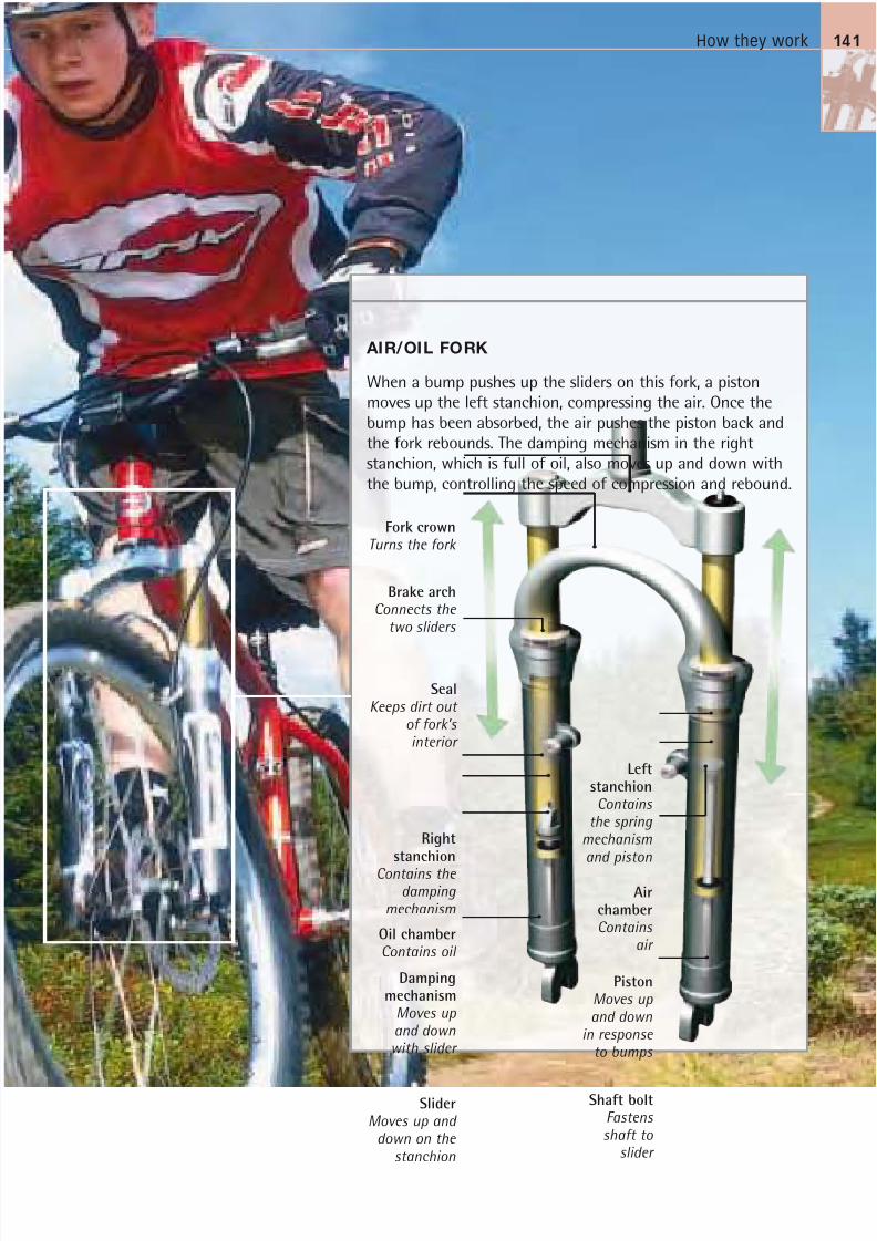
8/20/2019 Bike Repair Manual.downarchive
http://slidepdf.com/reader/full/bike-repair-manualdownarchive 141/160
How they work
When a bump pushes up the sliders on this fork, a piston
moves up the left stanchion, compressing the air. Once the
bump has been absorbed, the air pushes the piston back and
the fork rebounds. The damping mechanism in the rightstanchion, which is full of oil, also moves up and down with
the bump, controlling the speed of compression and rebound.
AIR/OIL FORK
Fork crownTurns the fork
Brake archConnects the
two sliders
SliderMoves up and
down on the
stanchion
Dampingmechanism
Moves up and downwith slider
PistonMoves up and down
in response to bumps
Oil chamberContains oil
SealKeeps dirt out
of fork’s interior
Rightstanchion
Contains the damping
mechanism
141
AirchamberContains
air
Shaft boltFastens shaft to
slider
LeftstanchionContains
the spring mechanism
and piston
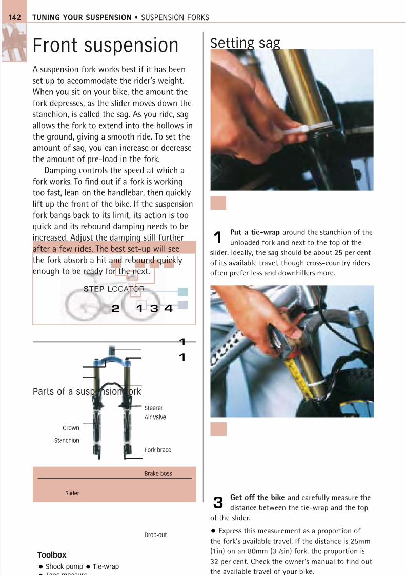
8/20/2019 Bike Repair Manual.downarchive
http://slidepdf.com/reader/full/bike-repair-manualdownarchive 142/160
STEP LOCATOR
TUNING YOUR SUSPENSION • SUSPENSION FORKS142
Front suspensionA suspension fork works best if it has been
set up to accommodate the rider’s weight.
When you sit on your bike, the amount the
fork depresses, as the slider moves down thestanchion, is called the sag. As you ride, sag
allows the fork to extend into the hollows in
the ground, giving a smooth ride. To set the
amount of sag, you can increase or decrease
the amount of pre-load in the fork.
Damping controls the speed at which a
fork works. To find out if a fork is working
too fast, lean on the handlebar, then quickly
lift up the front of the bike. If the suspensionfork bangs back to its limit, its action is too
quick and its rebound damping needs to be
increased. Adjust the damping still further
after a few rides. The best set-up will see
the fork absorb a hit and rebound quickly
enough to be ready for the next.
Setting sag
Put a tie-wrap around the stanchion of the
unloaded fork and next to the top of the
slider. Ideally, the sag should be about 25 per cent
of its available travel, though cross-country riders
often prefer less and downhillers more.
1
Get off the bike and carefully measure the
distance between the tie-wrap and the top
of the slider.
• Express this measurement as a proportion of
the fork’s available travel. If the distance is 25mm
(1in) on an 80mm (31 ⁄ 5in) fork, the proportion is
32 per cent. Check the owner’s manual to find out
the available travel of your bike.
3
Toolbox
Shock pump Tie-wrap
Tape measure
Parts of a suspension fork
1 3 4
Steerer
Air valve
Stanchion
Fork brace
Brake boss
Slider
Drop-out
Crown
1
2
1
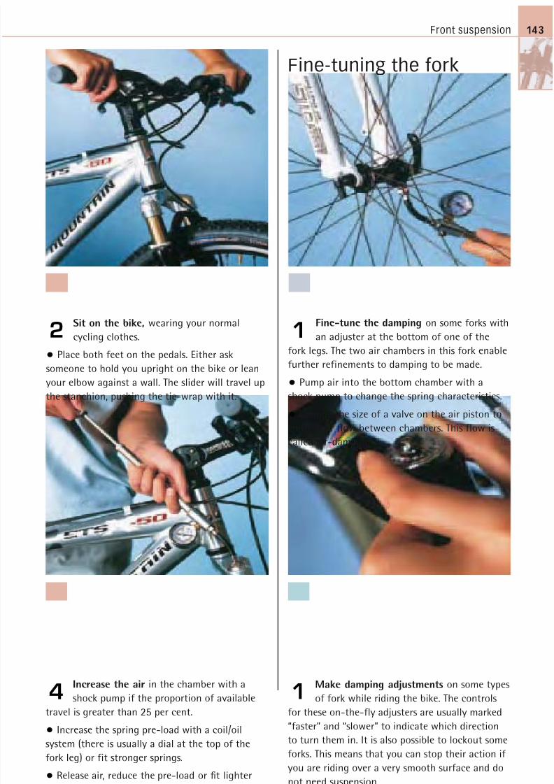
8/20/2019 Bike Repair Manual.downarchive
http://slidepdf.com/reader/full/bike-repair-manualdownarchive 143/160
Front suspension 143
Fine-tuning the fork
Sit on the bike, wearing your normal
cycling clothes.
• Place both feet on the pedals. Either ask
someone to hold you upright on the bike or lean
your elbow against a wall. The slider will travel up
the stanchion, pushing the tie-wrap with it.
2Fine-tune the damping on some forks with
an adjuster at the bottom of one of the
fork legs. The two air chambers in this fork enable
further refinements to damping to be made.
• Pump air into the bottom chamber with a
shock pump to change the spring characteristics.
• Change the size of a valve on the air piston tocontrol air flow between chambers. This flow is
called air-damping.
1
Make damping adjustments on some types
of fork while riding the bike. The controls
for these on-the-fly adjusters are usually marked
“faster” and “slower” to indicate which direction
to turn them in. It is also possible to lockout some
forks. This means that you can stop their action if
you are riding over a very smooth surface and do
not need suspension.
1
Increase the air in the chamber with a
shock pump if the proportion of available
travel is greater than 25 per cent.
• Increase the spring pre-load with a coil/oil
system (there is usually a dial at the top of the
fork leg) or fit stronger springs.
• Release air, reduce the pre-load or fit lighter
springs if the proportion is less than 25 per cent.
4
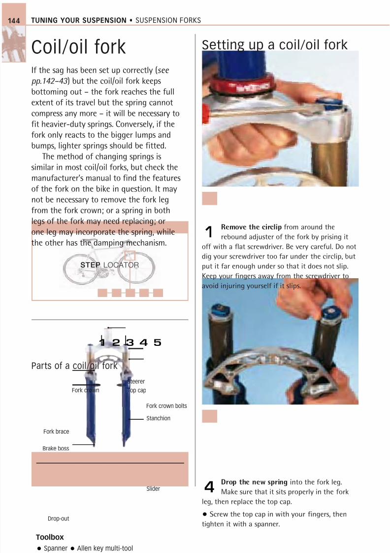
8/20/2019 Bike Repair Manual.downarchive
http://slidepdf.com/reader/full/bike-repair-manualdownarchive 144/160
TUNING YOUR SUSPENSION • SUSPENSION FORKS
Coil/oil forkIf the sag has been set up correctly (see pp.142–43 ) but the coil/oil fork keepsbottoming out – the fork reaches the full
extent of its travel but the spring cannotcompress any more – it will be necessary tofit heavier-duty springs. Conversely, if thefork only reacts to the bigger lumps andbumps, lighter springs should be fitted.
The method of changing springs issimilar in most coil/oil forks, but check themanufacturer’s manual to find the featuresof the fork on the bike in question. It may
not be necessary to remove the fork legfrom the fork crown; or a spring in bothlegs of the fork may need replacing; orone leg may incorporate the spring, whilethe other has the damping mechanism.
Setting up a coil/oil fork
Remove the circlip from around the
rebound adjuster of the fork by prising it
off with a flat screwdriver. Be very careful. Do not
dig your screwdriver too far under the circlip, but
put it far enough under so that it does not slip.
Keep your fingers away from the screwdriver to
avoid injuring yourself if it slips.
1
Drop the new spring into the fork leg.
Make sure that it sits properly in the fork
leg, then replace the top cap.
• Screw the top cap in with your fingers, then
tighten it with a spanner.
4
Toolbox
Spanner Allen key multi-tool
Flat screwdriver
Parts of a coil/oil fork
144
STEP LOCATOR
1 2 3 4 5
Fork crown Top cap
Fork crown bolts
Stanchion
Slider
Fork brace
Brake boss
Drop-out
Steerer

8/20/2019 Bike Repair Manual.downarchive
http://slidepdf.com/reader/full/bike-repair-manualdownarchive 145/160
Coil/oil fork
Undo the retaining bolts in the fork crown
so that you can drop the legs out. There are
usually four retaining bolts. Some fork crowns do
not have them, in which case undo a cap bolt at
the top of the fork leg to remove the springs.
2
Put the fork legs back
in the fork crown and
secure the retaining bolts.
• Follow the manufacturer’s
torque settings when replacing
the retaining bolts.
• Reset the sag of your forks(see pp.142–43 ).
5
Start to remove the top cap of the fork
leg with a spanner on the spanner flats,
then unscrew the cap the rest of the way out
with your fingers.
• Note how the spring is sitting in the fork leg,
then lift the spring out.
3
145
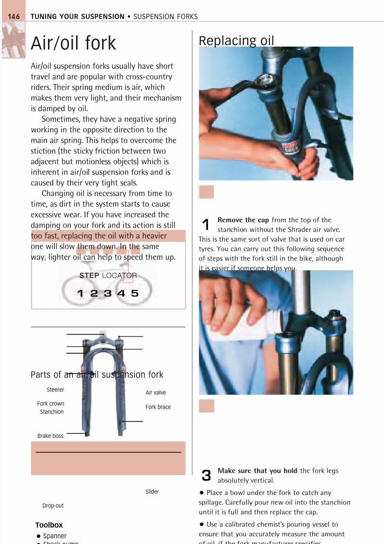
8/20/2019 Bike Repair Manual.downarchive
http://slidepdf.com/reader/full/bike-repair-manualdownarchive 146/160
STEP LOCATOR
TUNING YOUR SUSPENSION • SUSPENSION FORKS146
Air/oil forkAir/oil suspension forks usually have shorttravel and are popular with cross-countryriders. Their spring medium is air, which
makes them very light, and their mechanismis damped by oil.
Sometimes, they have a negative springworking in the opposite direction to themain air spring. This helps to overcome thestiction (the sticky friction between twoadjacent but motionless objects) which isinherent in air/oil suspension forks and iscaused by their very tight seals.
Changing oil is necessary from time totime, as dirt in the system starts to causeexcessive wear. If you have increased thedamping on your fork and its action is stilltoo fast, replacing the oil with a heavierone will slow them down. In the sameway, lighter oil can help to speed them up.
Replacing oil
Remove the cap from the top of the
stanchion without the Shrader air valve.
This is the same sort of valve that is used on car
tyres. You can carry out this following sequence
of steps with the fork still in the bike, although
it is easier if someone helps you.
1
Make sure that you hold the fork legs
absolutely vertical.
• Place a bowl under the fork to catch any
spillage. Carefully pour new oil into the stanchion
until it is full and then replace the cap.
• Use a calibrated chemist’s pouring vessel to
ensure that you accurately measure the amount
of oil, if the fork manufacturer specifies.
3
Toolbox
Spanner
Shock pump
Parts of an air/oil suspension fork
1 2 3 4 5
Steerer
Stanchion
Brake boss
Drop-out
Air valve
Slider
Fork braceFork crown
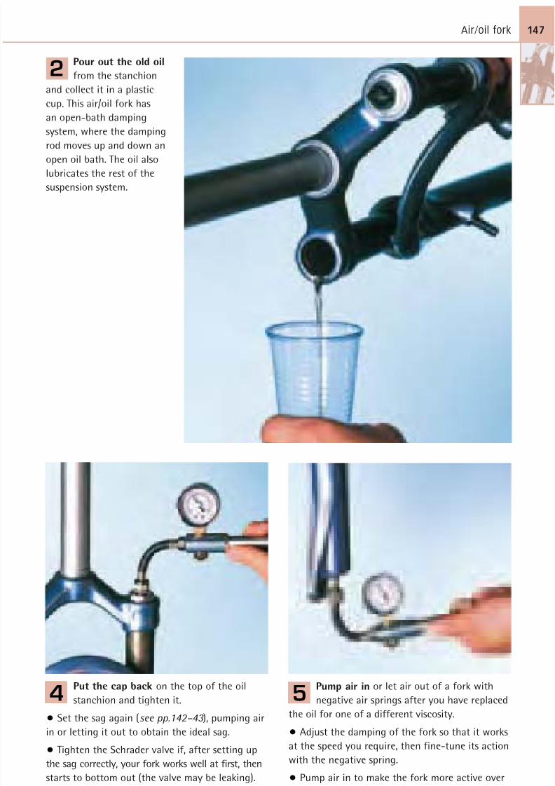
8/20/2019 Bike Repair Manual.downarchive
http://slidepdf.com/reader/full/bike-repair-manualdownarchive 147/160
Air/oil fork 147
Pour out the old oil
from the stanchion
and collect it in a plastic
cup. This air/oil fork has
an open-bath damping
system, where the damping
rod moves up and down anopen oil bath. The oil also
lubricates the rest of the
suspension system.
2
Pump air in or let air out of a fork with
negative air springs after you have replaced
the oil for one of a different viscosity.
• Adjust the damping of the fork so that it works
at the speed you require, then fine-tune its action
with the negative spring.
• Pump air in to make the fork more active over
small bumps. Let air out to make it less responsive.
5
Put the cap back on the top of the oil
stanchion and tighten it.
• Set the sag again (see pp.142–43 ), pumping air
in or letting it out to obtain the ideal sag.
• Tighten the Schrader valve if, after setting up
the sag correctly, your fork works well at first, then
starts to bottom out (the valve may be leaking).
Use a valve key from a car maintenance shop.
4
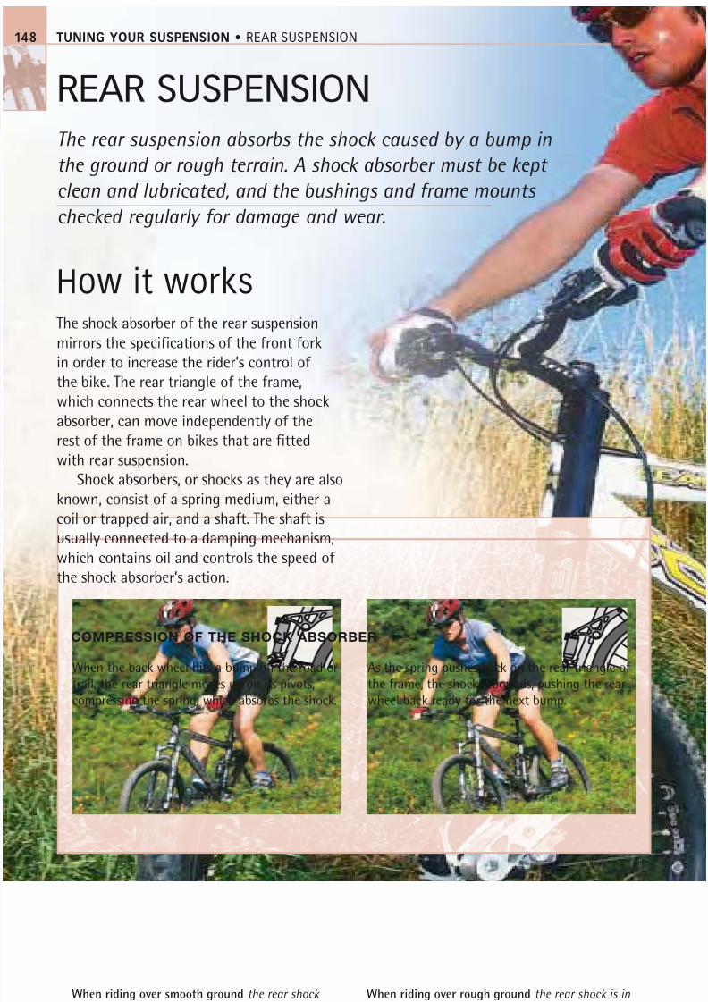
8/20/2019 Bike Repair Manual.downarchive
http://slidepdf.com/reader/full/bike-repair-manualdownarchive 148/160
TUNING YOUR SUSPENSION • REAR SUSPENSION
REAR SUSPENSION
The rear suspension absorbs the shock caused by a bump in
the ground or rough terrain. A shock absorber must be kept
clean and lubricated, and the bushings and frame mounts
checked regularly for damage and wear.
How it works
The shock absorber of the rear suspension
mirrors the specifications of the front fork
in order to increase the rider’s control ofthe bike. The rear triangle of the frame,
which connects the rear wheel to the shock
absorber, can move independently of the
rest of the frame on bikes that are fitted
with rear suspension.
Shock absorbers, or shocks as they are also
known, consist of a spring medium, either a
coil or trapped air, and a shaft. The shaft is
usually connected to a damping mechanism,which contains oil and controls the speed of
the shock absorber’s action.
When the back wheel hits a bump on the road or
trail, the rear triangle moves up on its pivots,
compressing the spring, which absorbs the shock.
As the spring pushes back on the rear triangle of
the frame, the shock rebounds, pushing the rear
wheel back ready for the next bump.
When riding over smooth ground the rear shock
absorber is in a neutral position.
When riding over rough ground the rear shock is ina compressed position to absorb bumps.
COMPRESSION OF THE SHOCK ABSORBER
148
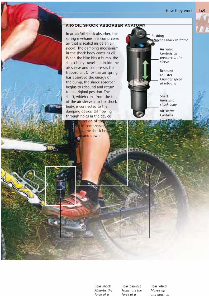
8/20/2019 Bike Repair Manual.downarchive
http://slidepdf.com/reader/full/bike-repair-manualdownarchive 149/160
How they work
AIR/OIL SHOCK ABSORBER ANATOMY
In an air/oil shock absorber, thespring mechanism is compressedair that is sealed inside an airsleeve. The damping mechanism
in the shock body contains oil.When the bike hits a bump, theshock body travels up inside theair sleeve and compresses thetrapped air. Once this air springhas absorbed the energy ofthe bump, the shock absorberbegins to rebound and returnto its original position. Theshaft, which runs from the topof the air sleeve into the shock
body, is connected to thedamping device. Oil flowingthrough holes in the deviceslows the action of the shockabsorber in compression andrebound as the shock bodytravels up and down.
Rear shockAbsorbs the force of a bump
Rear triangleTransmits the force of a bump to the rear shock
Rear wheelMoves up and down inresponse to bumps
BushingAttaches shock to frame
149
Air valve
Controls air pressure in the sleeve
ReboundadjusterChanges speed of rebound
ShaftRuns into
shock body Air sleeveContains compressed air
Shock bodyContains the damping device
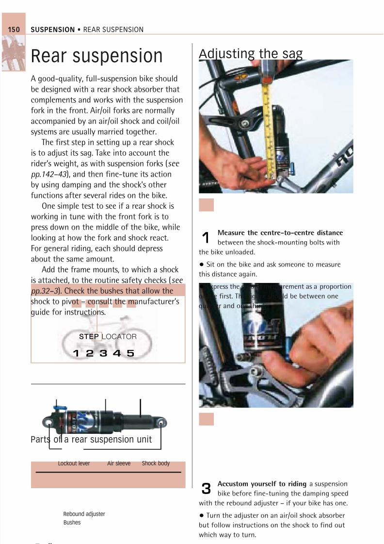
8/20/2019 Bike Repair Manual.downarchive
http://slidepdf.com/reader/full/bike-repair-manualdownarchive 150/160
STEP LOCATOR
SUSPENSION • REAR SUSPENSION150
Rear suspensionA good-quality, full-suspension bike shouldbe designed with a rear shock absorber thatcomplements and works with the suspension
fork in the front. Air/oil forks are normallyaccompanied by an air/oil shock and coil/oilsystems are usually married together.
The first step in setting up a rear shockis to adjust its sag. Take into account therider’s weight, as with suspension forks (see pp.142–43 ), and then fine-tune its actionby using damping and the shock’s otherfunctions after several rides on the bike.
One simple test to see if a rear shock isworking in tune with the front fork is topress down on the middle of the bike, whilelooking at how the fork and shock react.For general riding, each should depressabout the same amount.
Add the frame mounts, to which a shockis attached, to the routine safety checks (see pp.32–3 ). Check the bushes that allow the
shock to pivot – consult the manufacturer’sguide for instructions.
Adjusting the sag
Measure the centre-to-centre distance
between the shock-mounting bolts with
the bike unloaded.
• Sit on the bike and ask someone to measure
this distance again.
• Express the second measurement as a proportion
of the first. The figure should be between onequarter and one third.
1
Accustom yourself to riding a suspension
bike before fine-tuning the damping speed
with the rebound adjuster – if your bike has one.
• Turn the adjuster on an air/oil shock absorber
but follow instructions on the shock to find out
which way to turn.
• Do not set it too fast because this can upset
the handling of the bike.
3
Toolbox
Tape measure Shock pump
Parts of a rear suspension unit
1 2 3 4 5
Bushes
Rebound adjuster
Shock bodyLockout lever Air sleeve
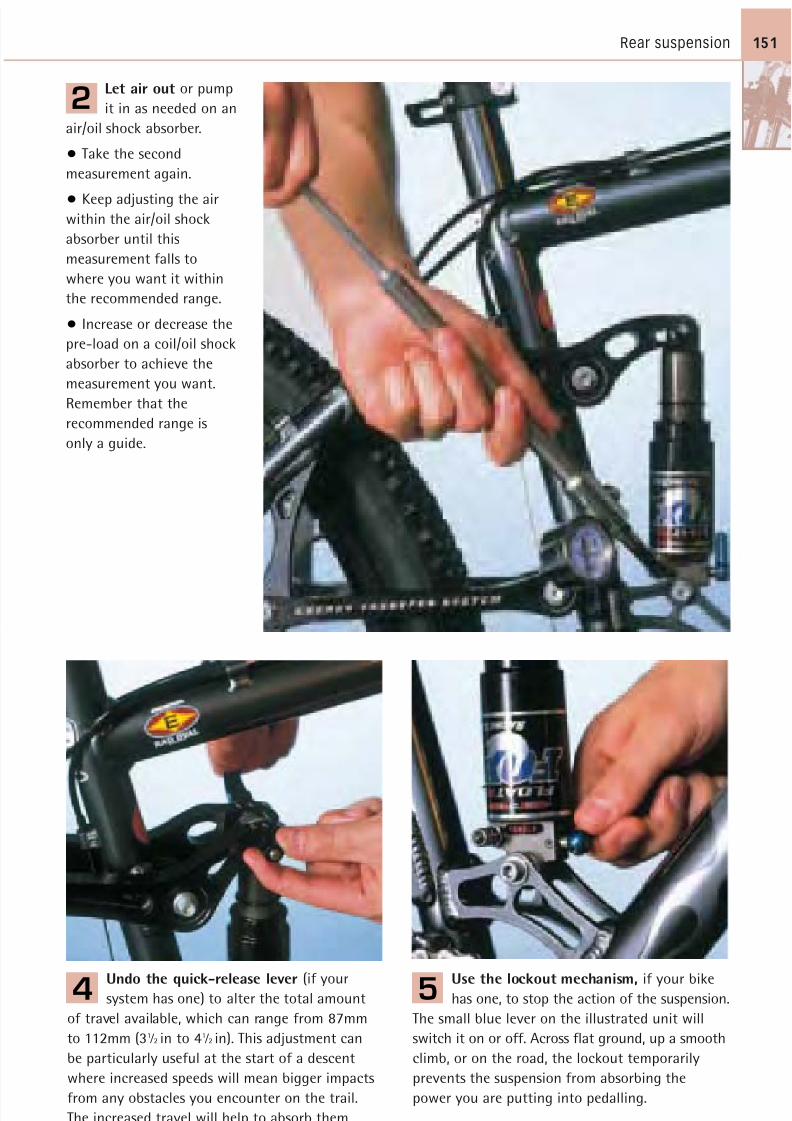
8/20/2019 Bike Repair Manual.downarchive
http://slidepdf.com/reader/full/bike-repair-manualdownarchive 151/160
Rear suspension 151
Let air out or pump
it in as needed on an
air/oil shock absorber.
• Take the second
measurement again.
• Keep adjusting the airwithin the air/oil shock
absorber until this
measurement falls to
where you want it within
the recommended range.
• Increase or decrease the
pre-load on a coil/oil shock
absorber to achieve the
measurement you want.
Remember that therecommended range is
only a guide.
2
Undo the quick-release lever (if your
system has one) to alter the total amount
of travel available, which can range from 87mm
to 112mm (31 ⁄ 2 in to 41 ⁄ 2 in). This adjustment can
be particularly useful at the start of a descent
where increased speeds will mean bigger impacts
from any obstacles you encounter on the trail.
The increased travel will help to absorb them.
4
Use the lockout mechanism, if your bike
has one, to stop the action of the suspension.
The small blue lever on the illustrated unit will
switch it on or off. Across flat ground, up a smooth
climb, or on the road, the lockout temporarily
prevents the suspension from absorbing the
power you are putting into pedalling.
5
8/20/2019 Bike Repair Manual.downarchive
http://slidepdf.com/reader/full/bike-repair-manualdownarchive 152/160
GLOSSARY152
GlossaryTerms in italic within an entry
are defined under their own
headings within the glossary.
ALLEN BOLT A threaded bolt
with a hexagonal depression
in the centre of its head.
ALLEN KEY Hexagonal-shaped
tool that fits Allen bolts.
BEARING A mechanism that
usually consists of a number
of ball-bearings and circular
channels, or races. It allowstwo metal surfaces to move
freely while in contact.
BLOCK Sprockets fitted to a
freewheel .
BOSS Threaded metal fixture
on a bicycle frame to which
an item such as a bottle cage
or a pannier rack is attached.
BOTTOM BRACKET Rotating
unit that connects the cranks
on either side of the bottom
bracket shell to each other.
BOTTOM OUT A term that
describes the point when
a suspension fork or shock
absorber reaches the limit
of its travel .BRAKE-LEVER HOOD The
body in which the brake
lever sits, connecting it to
the handlebar.
BRAKE TRAVEL The distance
a brake lever moves before
the brake pads engage the
braking surface on the rim
or hub of a wheel.
CABLE TIDY A small, soft-metal
cylinder that is closed at one
end and fits over the cut ends
of a cable to prevent fraying.
CASSETTE Sprockets that fit
on the freehub .
CHAINRING A toothed ring
attached to the cranks that
drives the chain and, in turn,
the sprockets and the rearwheel of a bicycle.
CHAINSET The assembly of
chainrings and cranks .
CHAINSTAY The frame tube
joining the bottom bracket
shell and rear drop-out .
CLEAT A plastic or metal plate
that fits to the sole of acycling shoe and engages
into a clipless pedal to hold
the foot on the pedal.
CLIPLESS PEDAL A pedal with
a mechanism to engage the
cleat on the sole of a cycling
shoe and hold it securely in
place. Called clipless because
they replaced pedals that hadtoe clips and straps.
COG A circular metal object
with teeth, sometimes used
as an alternative term for
sprocket . It usually describes
the parts within a hub gear
that can be combined to give
different gear ratios.
COMPRESSION The action of a suspension system when it
absorbs an impact from the
terrain. The term refers to the
compression of the spring.
CRANK The lever that joins
the pedals to the chainrings
and transfers energy from the
rider’s legs into the drivetrain
of the bike.
DAMPING The process that
absorbs the energy of an
impact transmitted through a
suspension system. It controls
the speed at which any form
of suspension responds to
uneven terrain.
DERAILLEUR GEARS A system
that shifts the chain between
sprockets on the rear wheel
(rear derailleur) and betweenchainrings attached to cranks
(front derailleur); it allows
multiple gearing on bikes.
See also Mech.
DOWN TUBE The frame tube
that joins the bottom-bracket
shell to the head tube .
DRIVETRAIN The assembly of
pedals, chainset , chain, andsprockets that drives the bike
forwards by transmitting leg
power into wheel rotation.
See also Transmission.
DROP-OUT A slotted plate at
the end of the fork legs and
stays, into which the axle of
a wheel is attached.
EXPANDER BOLT A bolt that
draws up a truncated cone
or triangle of metal inside a
metal tube in order to wedge
the tube in place. Commonly
found inside the stem of a
threaded headset .
FREEHUB A mechanism, part
of the hub, that allows the
rear wheel to rotate while the
pedals remain stationary.
FREEWHEEL A mechanism
that does the same job as a
freehub but can be screwed
on or off the hub.
GEAR An expression of the
chainring and sprocket
combination, linked by thechain, that propels the bike.
GEAR-SHIFTER The control
mechanism, usually on the
handlebar, used to initiate
gear-shifts.
GRUB SCREW A headless,
threaded bolt that has a
8/20/2019 Bike Repair Manual.downarchive
http://slidepdf.com/reader/full/bike-repair-manualdownarchive 153/160
Glossary 153
single diameter throughout
its length.
HEADSET The bearing unit
that attaches the forks to a
frame and allows them to
turn. There are two varieties:
threaded and threadless.
HEAD TUBE The frame tube
through which the steerer
tube runs.
HEXAGONAL BOLT OR NUT
A threaded bolt with ahexagonal-shaped head, or
a hexagonal-shaped nut that
fits on to a threaded bolt.
HYDRAULIC A mechanical
system that uses compressed
fluid to move an object.
LOCKRING/LOCKNUT A ring
or nut used to tighten on to
a threaded object and lockit in place.
MECH Short for mechanism.
Device that pushes the chain
on to a larger or smaller
chainring or sprocket . See
also Derailleur gears .
NEGATIVE SPRING A device
that works against the mainspring in a suspension
system. In compression, for
example, a negative spring
works to extend the fork,
helping to overcome the
effects of stiction.
NIPPLE The piece of metal
attached to the end of a
cable that secures the cable
in the control lever.
PLAY A term to describe any
looseness in mechanical parts.
QUICK-RELEASE MECHANISM
A lever connected to a skewer
that locks or releases a
component from the frame.
REBOUND A term to describe
the action of a suspension
system after it absorbs an
impact from the terrain.It refers to the extension
of the system’s spring.
SEAT POST A hollow tube
that holds the saddle and is
inserted into the seat tube .
SEAT STAY The frame tube
joining the bottom bracket
shell and rear drop-out .
SEAT TUBE The frame tube
that holds the seat post .
SIDEWALL Part of the tyre
between the tread and rim.
SPROCKET A cog turned by
the chain. Combined with
other sprockets, it forms a
cassette or block .
STEERER TUBE The tube that
connects the fork to the stem
and handlebar.
STEM The component that
connects the handlebar to
the steerer tube .
STICTION A term that
combines the words static
and friction. It describes thetension between moving and
static parts at rest, such as
the seals and stanchions in
a suspension fork.
STOPPER PIN The end of a
cantilever or V-brake return
spring that fits into a
locating hole on the bike’s
brake mounting bosses .
SUSPENSION An air/oil or a
coil/oil system that absorbs
the bumps from a trail or
road. The system is either
integrated into the fork or
connected to the rear wheel
via a linkage.
THREADS The spiral grooves
cut into metal that allow
separate parts to be screwed
or bolted together.
TOP TUBE The frame tube
that joins the seat tube to
the head tube .
TRANSMISSION A bike’s
transmission is made up of
those parts that transfer the
rider’s energy into forward
motion – the pedals, chain,
chainset and sprockets . Seealso Drivetrain.
TRAVEL A term that refers
to the total distance a
component moves in carrying
out its purpose. For example,
travel in a suspension fork is
the total distance the fork
has available to move in
order to absorb a shock.Brake travel is the distance
a brake lever must be pulled
before the brakes fully
contact the braking surface.
TREAD The central part of a
tyre that makes contact with
the ground.
VISCOSITY A rating system for
oils, which also refers to the
weight. A light oil has low
viscosity and moves quicker
than a heavy oil through a
given damping mechanism.
This results in a faster-acting
suspension system or reduced
damping.
WHEEL JIG A stand that holds
a wheel so that its rim runsbetween two jaws. Used in
truing a wheel after replacing
a broken spoke.
8/20/2019 Bike Repair Manual.downarchive
http://slidepdf.com/reader/full/bike-repair-manualdownarchive 154/160
Page numbers in italic indicate
diagrams showing the location
of parts and components.
Page numbers in bold indicate
entries where the maintenance
of the part is the main subject
on the page.
Aadjuster see barrel adjuster;
high and low adjuster; reachadjustment and adjuster
air sleeve 149, 149 , 150
air valve 13 , 106 , 146
air/oil fork 141, 141, 146–47,
150
air/oil shock absorber 149,
149 , 150
Allen bolt and key 13, 25 , 26,
152
anatomy of a bike 12–13
anti-seize compound 17, 31
axle nut 104, 134
axle
BMX bottom bracket 70, 76,
76
cartridge hub 98, 98 , 102,
102
cartridge-bearing bottom
bracket 70, 70 , 72, 72
hollow-axle bottom bracket
70, 71, 71, 74
open-bearing hub 98, 99, 99 ,
100, 100
pedal 13, 78, 78 , 80, 80
Bbackpedal brake see coaster
brake
ball-bearing see bearing
band-on front mech 52
bar-end 94
barrel adjuster
brake and brake lever 113 ,
116 , 121, 124 , 134
gear-shifter 48 , 60
rear mech 12 , 54
barrel nipple 116, 116 , 124
barrel, chain 63, 63
basic bike 10, 10–11, 14–15, 15
bearing 152
BMX bottom bracket 70,
76-7, 76
cartridge-bearing bottombracket 70-3, 70 , 72
headset 13 , 88, 88 , 89, 89 , 93
hollow-axle bottom bracket
70-1, 71, 74-5, 74
hub gear 56
hub 98, 98 , 99, 99 , 100, 102,
102
lubricating 30
pedal 78, 78 , 80
bench vice 25
bleeding hydraulic disc brake
132–33
block, freewheel 66–7, 152
BMX bike 16, 17, 17
bottom bracket 70, 76 , 76–7
U-brake 124 , 124–25
bolt and nuttightening 24, 26
see also Allen bolt and key;
axle nut; cable-clamp bolt;
expander bolt; hexagonal bolt
and nut; locknut; lockring;
stem cap and stem cap bolt
boss 112 , 142 , 144 , 146 , 152
bottom bracket 12 , 17, 70, 152
BMX 70, 76 , 76–7
cartridge-bearing 70 , 70, 71,
72 , 72–3
hollow-axle 70, 71, 71, 74 ,
74–5
tools 25
bottom cup 13 , 88, 88 , 90, 90 , 92
bracket see bottom bracket
brake arch 141
brake arm 12
hub-mounted brakes134 ,
136
rim brake 112, 112 , 113 , 120 ,
124
brake boss 112 , 142 , 144 , 146
brake cable 113 , 114
cable disc brake 128, 128
cable tidy 26, 116
calliper brake 112cantilever brake 112, 116, 122
cutting outer 26
drop handlebar 114–15
hub-mounted brake 126
lubricating 30-1
regular maintenance 15, 15 ,
17
roller brake 134–35
side-pull calliper brake 124
split or frayed 39
V-brake 112, 112 , 116–17
brake fluid 126, 127, 130,
132–33
brake hose 126, 126 , 127, 127 ,
130, 130 , 132
brake lever hood 45, 45 , 96 ,
114 , 152
brake lever 13 , 15
brake travel 152, 153
calliper brake 118
drop handlebar 96, 114, 114 ,
122
gear-shifter combination
45, 46
hub-mounted brake 126
hydraulic 126, 127, 127 , 130position/reach adjustment
18, 19
rim brake 112, 113, 113
side-pull calliper brake 124
straight handlebar 94, 116,
116
INDEX154
Index

8/20/2019 Bike Repair Manual.downarchive
http://slidepdf.com/reader/full/bike-repair-manualdownarchive 155/160
Index 155
brake pad 12 , 15, 16, 17, 38
cable disc brake 126,
128–29
calliper brake 118–19, 118
cantilever brake 122, 122
coaster brake 126
hub-mounted brake 126
hydraulic disc brake 126, 126
rim brake 112, 112 , 113
roller brake 126
side-pull calliper brake 125
V-brake 120, 120
brake shoe 118 , 120 , 122
brake 11, 11, 12
regular maintenance 15, 17
safety check 32, 38, 39
servicing timetable 34–5
troubleshooting chart 36–7
see also cable disc brake;
calliper brake; cantilever
brake; coaster brake;
hub-mounted brake;
hydraulic disc brake; rim
brake; roller brake; U-brake;
V-brake
braking surface 12 , 112, 126
braze-on front mech 52, 52
bunnyhopping 140
bushing 148, 149 , 150, 150
Ccable-clamp bolt 112 , 122 ,
124 , 134
cable clamp 44, 44 , 50 , 51, 54
cable cutters and puller 25 ,
26
cable disc brake 126, 128 ,
128–29, 130
cable-guide tube 12 , 112, 112
cable inner 44, 45 , 46, 112 , 113 ,
116
cable outer 26, 39, 44–9, 113 ,
116, 117, 128
cable port 48
cable tidy 26, 116, 152
cable 44-9
lubricating 30–1, 46
regular maintenance 15, 15 ,
17
split or frayed 39
see also brake cable; cable
inner; cable outer; gear cable;
straight handlebar brake lever
and cable
calliper brake 17 , 104, 112, 118 ,
118–19
side-pull calliper brake 124 ,
124–25
calliper (hub-mounted brake)cable disc brake 128
hydraulic disc brake 126, 126 ,
127, 130
Campagnolo part
calliper brake 119
hub 100
shifter and cable 45, 46 ,
46–7, 114
cantilever brake 104, 112, 116,
122 , 122–23
carbon fibre 17, 31
carrier unit 56, 56
cartridge-bearing bottom
bracket 70 , 70–3, 72
cartridge hub 98 , 98, 102 ,
102–3
cassette body12
, 62,62
, 66cassette 62, 66–7, 152
bike anatomy 12 , 62 , 66
cleaning 28–9
regular maintenance 17
tool 25 , 29, 66
chainring 38, 62, 63, 152
bike anatomy 13 , 15 , 51, 63 ,
68 , 76
chain 62–5
bike anatomy 13 , 40 , 62 , 63
coaster brake efficiency 136
estimating wear 64
lubricating 30, 41
regular maintenance 15, 15 ,
chain 41
chain (continued)
shifting gear 44, 50, 51
tool 25 , 64
troubleshooting chart 36–7
chainset 62, 63 , 68 , 68–9, 76,
152
chainstay 12 , 152
children's bike
coaster brake 126, 136 ,
136–37
setting up 20–1
side-pull calliper brake 124 ,
124–25
cleaning and degreasing 28–9,30
cleat-release mechanism,
pedal 80 , 82, 82 , 83
cleat, pedal 78, 82, 84 , 84–5,
152
clipless pedal 41, 78, 82 , 82–3,
83 , 84, 152
coaster brake 126, 136 , 136–37
cog 152
coil/oil fork 144 , 144–45, 150
common problems chart 36–7
commuting bike 12
component see part
compression 140, 141, 148, 152
cone 76 , 78, 78 , 99
crank 152
bottom bracket 70,70
,71
chainset and drivetrain
(right-hand crank) 13 , 68
crank-removing tool 25 , 68
pedal 78, 78 , 80
cup
BMX bottom bracket 76, 76
see also bottom cup; fixed
cup; free cup
Ddamping and damping
mechanism 152
fork (front suspension) 140,
141, 141, 142, 143, 146
8/20/2019 Bike Repair Manual.downarchive
http://slidepdf.com/reader/full/bike-repair-manualdownarchive 156/160
INDEX156
damping and damping
mechanism (continued)
shock absorber (rear
suspension) 148, 149, 149 ,
150
danger see safety
degreasing and cleaning 28–9,
30
derailleur chain 64–5
derailleur gear 12, 62, 64, 98,
152
regular maintenance 15, 17,
see also front mech; rear
mechdirt and oil, removing 28–9, 30
disc brake
cable 126, 128 , 128–29, 130
hydraulic 126 , 126, 130 ,
130–33
down tube 12 , 152
driver unit 56, 56
drivetrain 10 , 13 , 152
see also chain; chainring;
chainset; pedal; sprocket
drop handlebar 16, 17 , 94, 96–7
brake cable 114–15
brake lever 96, 114, 114 , 122
gear cable 46–7
drop-out 12 , 104 , 136 , 142 , 144 ,
146 , 152
drum brakesee
roller brakedry lube 30
Dual Control gear shifter and
cable, 48 , 49
E FErgoshift 46 , 114
expander bolt 152
fixed cup 70, 70 , 72
flange, hub 62 , 98 , 100 , 102
flat pedal 78, 78
folding bike 14, 15, 15
foot retention mechanism 13 ,
78, 82–3, 82 , 83
see also pedal cleat
fork brace 142 , 144 , 146
fork crown 13 , 88, 88 , 141, 142 ,
144 , 146
fork drop-out 12 , 104 , 142 , 144 ,
146 , 152
fork leg 13 , 144
fork 10, 11, 17 , 104 , 140–43,
142
air/oil fork 141, 141, 146–47,
150
coil/oil fork 144, 144-5, 150
headset connection 88, 89
frame 10, 10 , 12 , 17 , 32–3, 148
free cup 70, 70 , 72
freehub 100, 100 , 152
freewheel 62, 62 , 66 , 66-7, 98,
152
front fork see fork
front hub 98, 99, 99 , 100, 102
front mech 30, 41, 44, 50–3
bike anatomy 13 , 15 , 51
front suspension see fork
front wheel removal 105
Ggear cable 44–9, 50, 58–9
cutting outer 26
lubricating 30–1, 46
regular maintenance 15, 15
split or frayed 39Sturmey Archer 3-speed gear
58, 60
gear-shifter 10–11, 44–9, 50,
60, 152
bike anatomy 11, 13 , 45 , 46 ,
48
gear 10, 33, 39, 152
see also derailleur gear; hub
geargeneral use bike 10, 10–11,
14–15, 15
grease
applying 30–1
removing 28–9, 30
servicing timetable 34–5
grease (continued)
weatherproofing treatment
40–1
see also main entries for
individual bike parts for
specific lubrication
instructions
Grip Shift & cable, SRAM 48 , 49
grip 13 , 94
grub screw 152
H
handlebar stem 13 , 88 , 89, 89 ,92
handlebar tape 47, 96, 96 , 97
handlebar 32
adjusting on children's bike
20–1
see also drop handlebar; riser
bar; straight handlebar
head tube 13 , 88, 90, 153
headset 17, 17 , 40, 40 , 88–93,
153
hexagonal bolt and nut 153
high and low adjuster, mech 50 ,
51, 52–3, 52 , 55
hose, brake 126, 126 , 127, 127 ,
130, 130 , 132
hub body 98 , 99 , 100 , 102
hub flange62
,98
,100
,102
hub gear 12, 15 , 15, 56 , 56–61,
58 , 98
hub-mounted brake 126–27
see also cable disc brake;
coaster brake; hydraulic disc
brake; roller brake
hub 12 , 13 , 98, 128 , 136
cartridge hub 98 , 98, 102 ,
102–3
open-bearing hub 98, 99 , 99,
100 , 100–1
hybrid bike 10, 10–11, 14,
15, 15
V-brake cable replacement
116–17
8/20/2019 Bike Repair Manual.downarchive
http://slidepdf.com/reader/full/bike-repair-manualdownarchive 157/160
Index 157
hydraulic brake lever 126, 127,
127 , 130
hydraulic disc brake 126 , 126,
130 , 130–33
hydraulic system 153
Iinner tube 13 , 106 , 106–7, 134,
136
inner see cable inner
Isis bottom bracket axle 72
Italian-threaded bottom
bracket 72
J K jockey wheel 12 , 50, 50 , 51,
54–5, 54 , 62
joining pin 63, 63 , 64
knurled retainer 78 , 80
Llever hood 45, 45 , 96 , 114 ,
152
lever see brake lever; gear-
shifter
link 63, 63 , 64
locknut 12 , 70, 76, 76 , 78 , 92 ,
99,100
lockout mechanism 150 , 151
lockring 153
bottom bracket 71
cartridge hub 102
cassette 62
headset 89
hub 98
long-nosed pliers 25 , 26
Look road pedal 83 , 83
low and high adjuster, mech 50 ,
51, 52–3, 52 , 55
lubrication
applying 30–1
removing 28–9, 30
servicing timetable 34–5
lubrication (continued)
viscosity 153
weatherproofing treatments
40–1
see also main entries for
individual bike parts for
specific lubrication
instructions
Mmallet 25
manual 7, 24
mech cage 51, 52, 52
mech plate 12 , 50, 50 , 51
mech 10 , 40 , 153
see also front mech; rear
mech
mountain bike 12–13 , 16, 17,
17 , 94
gear cable 48–9
off-road pedal 82 , 82
V-brake and brake cable 116,
120, 122
mudguard 40 , 41
multi-tools 25
Nnegative spring 146, 153
Nexus hub gear, Shimano56
,56–61, 58
nipple 153
brake lever 113 , 114, 114 , 116,
116 , 124
spoke 108
nut and bolt
tightening 24, 26
see also Allen bolt and key;
axle nut; cable-clamp bolt;expander bolt; hexagonal bolt
and nut; locknut;
lockring; stem cap and stem
cap bolt
OOctalink bottom bracket axle 72,
72
off-road pedal 82 , 82
oil
applying 30–1
changing, air/oil fork 146–47
removing 28–9, 30
servicing timetable 34–5
viscosity 153
weatherproofing treatment
40–1
see also main entries for
individual bike parts for
specific lubrication
instructions
open-bearing hub 98, 99 , 99,
100 , 100–1
outer arm, front mech 51
outer see cable outer
owners' manual 7, 24
Pparts
bike anatomy 12–13
safety check 32–3, 38–9
servicing timetable 34–5
technological improvements
10–11, 63
troubleshooting chart 36–7
weatherproofing 40–1
worn 38–9
pear nipple 114, 114 , 124
pedal axle 13 , 78, 78 , 80, 80
pedal body 13 , 78 , 80
pedal cleat 78, 82, 84 , 84–5,
152
release mechanism 80 , 82, 82 ,
83
pedal 10 , 11, 17, 41, 78–83
bike anatomy 13 , 17 , 40 , 63 ,
78
8/20/2019 Bike Repair Manual.downarchive
http://slidepdf.com/reader/full/bike-repair-manualdownarchive 158/160
INDEX158
piston
fork 141, 141
hydraulic brake and brake
lever 126, 127
pivot bolt 112 , 120 , 124
pivot point 41, 50, 51, 51, 52 ,
54 , 148
plate spring 50 , 51
play 153
pliers 25 , 26
pre-ride safety check 32–3, 38–9
problem-solving chart 36–7
profile 62
pump 25
puncture repair 106–7, 134, 136
Q Rquick-release lever and
mechanism 153
calliper brake 119
hub axle 98, 99, 99
wheel 12 , 62 , 104 , 104–5
quill 89, 89 , 92
race 70 , 88, 90 , 92 , 99
Rapidfire gear-shifter and cable
48–9
reach adjustment and adjuster
18, 19, 116
rear brake 12 , 17
rear hub12
, 98, 100rear mech 30, 41, 44, 50–1, 54–5
bike anatomy 12 , 15 , 50 , 62
rear shock absorber (rear
suspension) 17 , 148–51, 149 ,
150
rear wheel removal 104–5
rebound 140, 141, 148, 149, 153
rebound adjuster 149 , 150
release mechanismpedal 80 , 82, 82 , 83
quick-release see quick-
release lever and mechanism
retainer, knurled 78 , 80
retention mechanism 13 , 78,
82–3, 82 , 83
retention mechanism
(continued)
see also pedal cleat
riding position
adult 18–19
child 20–1
right-hand crank 13 , 68
rim brake 104, 112–13
see also calliper brake;
cantilever brake; side-pull
calliper brake; U-brake;
V-brake
rim 13 , 39, 106 , 108
truing wheel 108–9
ring clamp 48
ring gear 56
riser bar 94, 116
road bike 16, 17, 17
drop handlebar brake cable
114–15
road pedal 83 , 83
roller bearing see bearing
roller brake 126, 134 , 134–35
Ssaddle 12
adjustment 18–21
safety 7, 32–3, 38–9
sag 142–43, 144, 150–51
salt 40satellite 56, 56 , 58 , 60–1, 136
schedule, servicing 34–5
seat pin and stem 21, 31, 41
seat post collar 40, 40
seat post 12 , 33, 153
seat stay 12 , 153
seat tube 12 , 33, 153
servicing schedule 34–5
setting up 18–21
shaft 148, 149, 149
shearing 24, 26
shifters/shift lever see
gear-shifter
Shimano part
calliper brake 118–19
Shimano part (continued)
chain 64–5, 64
gear-shifter and cable 45, 45 ,
46 , 46–9, 48
hub 100
Nexus hub gear 56 , 56–61,
58
Octalink bottom bracket axle
72, 72
road and off-road pedal 82 ,
82, 83 , 83
shock absorber (shock) 17 ,
148–51, 149 , 150
shock body 149, 149 , 150
shoe see brake shoe; pedal cleat
side-pull calliper brake 124 ,
124–25
sidewall 153
sleeve 70, 149, 149 , 150
slider 13 , 140, 141, 141, 142 ,
144 , 146
spanner 25 , 26
specialist bike 16
see also BMX; mountain bike;
road
split-link chain 64 , 65
spoke key and spoke ruler 25
spoke 13 , 106 , 108 , 108–9
spring
brake 112, 126
fork 140, 144, 146negative spring 146, 153
plate spring 50 , 51
shock absorber 148, 149
sprocket 12 , 38, 51, 56, 62, 62 ,
66 , 153
square-tapered bottom bracket
axle 72
SRAM Grip Shift and cable 48 , 49
stanchion 140, 141, 141, 142 ,144 , 146
star washer 88, 88
steerer tube 13 , 88, 88 , 153
steerer 89, 89 , 142 , 144 , 146
steering 13 , 34–5, 36–7
see also handlebar; threaded
8/20/2019 Bike Repair Manual.downarchive
http://slidepdf.com/reader/full/bike-repair-manualdownarchive 159/160
Index 159
steering (continued)
headset; threadless headset;
top cup
stem, handlebar 13 , 88 , 89, 89 ,
92, 153
stem cap and stem cap bolt 13 ,
88, 88 , 90
stiction 146, 153
stopper pin 153
straddle and straddle wire 122,
124
straight handlebar 13 , 17 , 94 ,
94–5
brake lever and cable 94, 116 ,116–17
Sturmey Archer 3-speed gear
58, 60
suspension 153
compression and rebound
140, 141, 148, 149, 152,
153
front suspension see fork
mountain bike 16, 17
negative spring 146, 153
rear suspension (shock) 17 ,
148–51, 149 , 150
sag 142–43, 144, 150–51
servicing timetable 34–5
suspension fork see fork
troubleshooting chart 36–7
see also damping and
damping mechanism
Ttape, handlebar 47, 96, 96 , 97
threaded headset 88, 89, 89 , 92 ,
92–3
threaded steerer 89, 89
threadless headset 88, 88 , 90–1,91
thread 153
3-piece and triple chainset 10 , 76
tightening nut and bolt 24, 26
Time off-road and road pedal
82 , 82, 83 , 83
timetable, servicing 34–5
tools and workshop 24–7
top cup 13 , 88, 88 , 89, 89 , 90,
92, 92
top tube 13 , 153
torque gauge and setting 24
transmission 34–5, 36–7, 41, 98,
153
tools 25
travel 50, 151, 152, 153
tread 153
tread wear 39
triple and 3-piece chainset 10 ,
76troubleshooting chart 36–7
truing wheel 108–9
tube see chainstay; down tube;
head tube; inner tube; seat
stay; steerer tube; top tube
tyre bead 13
tyre 10, 11, 13 , 15 , 17 , 106
puncture repair 106–7, 134,
136
regular maintenance 15
safety check 32, 39
U V U-brake 124 , 124–25
urban commuting bike 12
utility bike 14, 15,15
V-brake 17 , 104, 112, 112 ,
116–17, 120 , 120–21,
122
valve 13 , 106 , 146
vice, bench 25
viscosity 153
Wwashing and degreasing 28–9,
30
weatherproofing and wet
weather 40–1
wedge 88, 89, 89
wet lube 30
wheel jig 108, 153
wheel 10, 10 , 13 , 104 , 104–9,
106
children's bike sizes 20
cleaning 28–9
safety check 32, 39
servicing timetable 34–5
troubleshooting chart 36–7
truing 108–9
see also hub; rim; spoke; tyre
workshop and tools 24–7
workstand 25
8/20/2019 Bike Repair Manual.downarchive
http://slidepdf.com/reader/full/bike-repair-manualdownarchive 160/160
ACKNOWLEDGMENTS160
AcknowledgmentsAuthor’sacknowledgments
Pip Morgan and Richard Gilbertfor their patient and diplomatic
editorial work.
Ted Kinsey for designing
everything so that the writing
makes sense.
Dave Marsh of the Universal
Cycle Centre for technical
advice regarding road bikes.
Wayne Bennett of Don’t Push ItMountain Bikes for advice
regarding mountain bikes.
Tim Flooks of TF Tuned Shox for
advice regarding suspension.
Gerard Brown for his excellent
pictures and Guy Andrews for
getting together the equipment
we needed to show all the
aspects of bike maintenance
Publisher’sacknowledgments
Design: Janice English, SimonMurrell, Dawn Young
DTP Design: Gemma Casajuana
Photoshoot Art Direction:
Jo Grey
Picture Research: Carolyn Clerkin
Proofreading: Lynn Bresler
Illustrations: Kevin Jones and
Matthew White at Kevin Jones
Associates, Tim Loughead at
Precision Illustration Ltd.
Additional photography: Jill
and Steve Behr at Stockfile
Models: Jay Black, Chris
Hopkins, James Millard, Simon
Oon, Helen Rosser, Rochele
Whyte
Cycling models: Hsu Minh
Chung Jamie Newell Claire
Schwinn BMX; Caroline Griffiths
at Madison for Profile, Shimano,
Finish Line, Park, and Ridgeback;
Ross Patterson and JonHoldcroft at ATB sales for
Electra and Marin bikes;
Collette Clensy at Giant Bikes;
Adrian at Pashley bicycles;
Sean and Stuart at Evans Cycles,
Wandsworth; Cedric at Luciano
Cycles, Clapham; Sam at
Bikepark, Covent Garden;
Richard at Apex Cycles,
Clapham; Graham at SRAM;Shelley at Continental; Trek UK.
Picture credits
The publisher would like to
thank the following for their
kind permission to reproduce
their photograph:
56-7: Stockfile/Steve Behr