Embed Size (px)
Citation preview
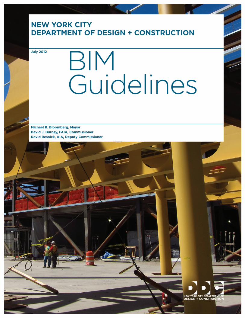
NEW YORK CITY DEPARTMENT OF DESIGN + CONSTRUCTION
July 2012
Michael R. Bloomberg, Mayor David J. Burney, FAIA, Commissioner David Resnick, AIA, Deputy Commissioner
BIMGuidelines
1
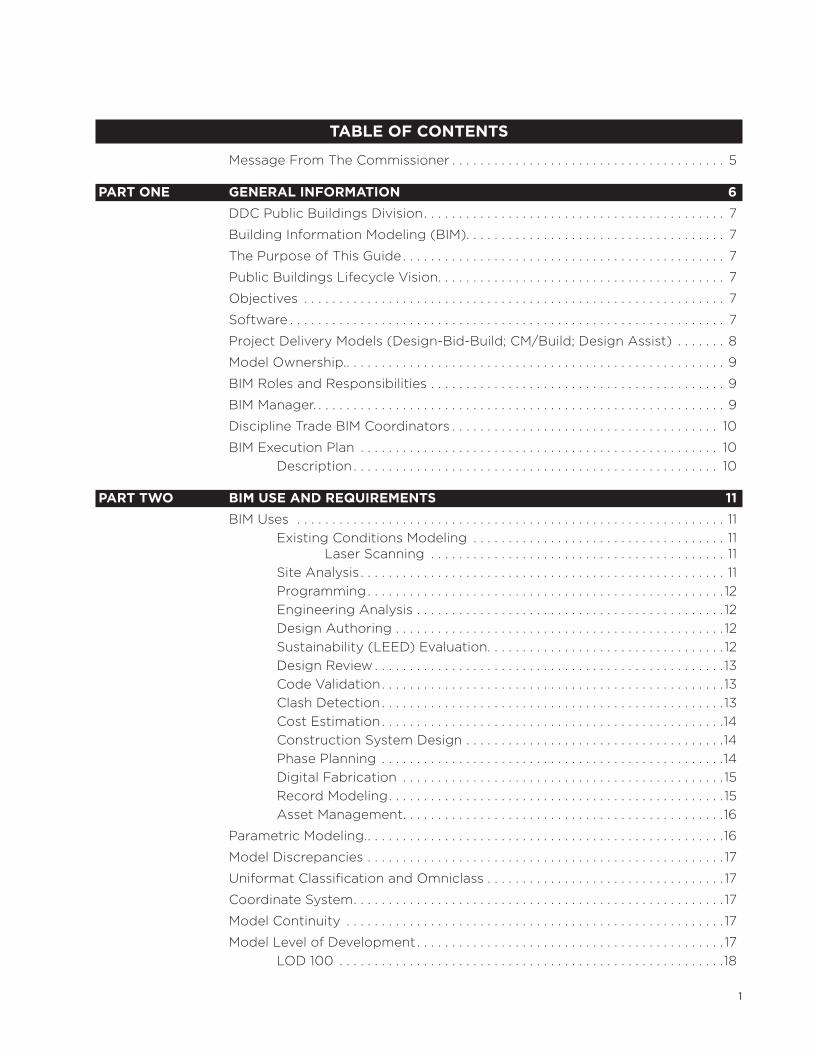
TABLE OF COnTEnTs
Message From The Commissioner . . . . . . . . . . . . . . . . . . . . . . . . . . . . . . . . . . . . . . . 5
PART OnE GEnERAL InFORMATIOn 6
DDC Public Buildings Division . . . . . . . . . . . . . . . . . . . . . . . . . . . . . . . . . . . . . . . . . . . 7
Building Information Modeling (BIM) . . . . . . . . . . . . . . . . . . . . . . . . . . . . . . . . . . . . . 7
The Purpose of This Guide . . . . . . . . . . . . . . . . . . . . . . . . . . . . . . . . . . . . . . . . . . . . . . 7
Public Buildings Lifecycle Vision . . . . . . . . . . . . . . . . . . . . . . . . . . . . . . . . . . . . . . . . . 7
Objectives . . . . . . . . . . . . . . . . . . . . . . . . . . . . . . . . . . . . . . . . . . . . . . . . . . . . . . . . . . . . 7
Software . . . . . . . . . . . . . . . . . . . . . . . . . . . . . . . . . . . . . . . . . . . . . . . . . . . . . . . . . . . . . . 7
Project Delivery Models (Design-Bid-Build; CM/Build; Design Assist) . . . . . . . 8
Model Ownership . . . . . . . . . . . . . . . . . . . . . . . . . . . . . . . . . . . . . . . . . . . . . . . . . . . . . . . 9
BIM Roles and Responsibilities . . . . . . . . . . . . . . . . . . . . . . . . . . . . . . . . . . . . . . . . . . 9
BIM Manager . . . . . . . . . . . . . . . . . . . . . . . . . . . . . . . . . . . . . . . . . . . . . . . . . . . . . . . . . . . 9
Discipline Trade BIM Coordinators . . . . . . . . . . . . . . . . . . . . . . . . . . . . . . . . . . . . . . 10
BIM Execution Plan . . . . . . . . . . . . . . . . . . . . . . . . . . . . . . . . . . . . . . . . . . . . . . . . . . . 10Description . . . . . . . . . . . . . . . . . . . . . . . . . . . . . . . . . . . . . . . . . . . . . . . . . . . . 10
PART TWO BIM UsE AnD REQUIREMEnTs 11
BIM Uses . . . . . . . . . . . . . . . . . . . . . . . . . . . . . . . . . . . . . . . . . . . . . . . . . . . . . . . . . . . . . 11Existing Conditions Modeling . . . . . . . . . . . . . . . . . . . . . . . . . . . . . . . . . . . . 11
Laser Scanning . . . . . . . . . . . . . . . . . . . . . . . . . . . . . . . . . . . . . . . . . . 11Site Analysis . . . . . . . . . . . . . . . . . . . . . . . . . . . . . . . . . . . . . . . . . . . . . . . . . . . . 11Programming . . . . . . . . . . . . . . . . . . . . . . . . . . . . . . . . . . . . . . . . . . . . . . . . . . . 12Engineering Analysis . . . . . . . . . . . . . . . . . . . . . . . . . . . . . . . . . . . . . . . . . . . . 12Design Authoring . . . . . . . . . . . . . . . . . . . . . . . . . . . . . . . . . . . . . . . . . . . . . . . 12Sustainability (LEED) Evaluation . . . . . . . . . . . . . . . . . . . . . . . . . . . . . . . . . . 12Design Review . . . . . . . . . . . . . . . . . . . . . . . . . . . . . . . . . . . . . . . . . . . . . . . . . . 13Code Validation . . . . . . . . . . . . . . . . . . . . . . . . . . . . . . . . . . . . . . . . . . . . . . . . . 13Clash Detection . . . . . . . . . . . . . . . . . . . . . . . . . . . . . . . . . . . . . . . . . . . . . . . . . 13Cost Estimation . . . . . . . . . . . . . . . . . . . . . . . . . . . . . . . . . . . . . . . . . . . . . . . . .14Construction System Design . . . . . . . . . . . . . . . . . . . . . . . . . . . . . . . . . . . . .14Phase Planning . . . . . . . . . . . . . . . . . . . . . . . . . . . . . . . . . . . . . . . . . . . . . . . . .14Digital Fabrication . . . . . . . . . . . . . . . . . . . . . . . . . . . . . . . . . . . . . . . . . . . . . . 15Record Modeling . . . . . . . . . . . . . . . . . . . . . . . . . . . . . . . . . . . . . . . . . . . . . . . . 15Asset Management . . . . . . . . . . . . . . . . . . . . . . . . . . . . . . . . . . . . . . . . . . . . . .16
Parametric Modeling . . . . . . . . . . . . . . . . . . . . . . . . . . . . . . . . . . . . . . . . . . . . . . . . . . . .16
Model Discrepancies . . . . . . . . . . . . . . . . . . . . . . . . . . . . . . . . . . . . . . . . . . . . . . . . . . . 17
Uniformat Classification and Omniclass . . . . . . . . . . . . . . . . . . . . . . . . . . . . . . . . . . 17
Coordinate System . . . . . . . . . . . . . . . . . . . . . . . . . . . . . . . . . . . . . . . . . . . . . . . . . . . . . 17
Model Continuity . . . . . . . . . . . . . . . . . . . . . . . . . . . . . . . . . . . . . . . . . . . . . . . . . . . . . . 17
Model Level of Development . . . . . . . . . . . . . . . . . . . . . . . . . . . . . . . . . . . . . . . . . . . . 17LOD 100 . . . . . . . . . . . . . . . . . . . . . . . . . . . . . . . . . . . . . . . . . . . . . . . . . . . . . . .18
2
LOD 200 . . . . . . . . . . . . . . . . . . . . . . . . . . . . . . . . . . . . . . . . . . . . . . . . . . . . . . .18LOD 300 . . . . . . . . . . . . . . . . . . . . . . . . . . . . . . . . . . . . . . . . . . . . . . . . . . . . . . .19LOD 400 . . . . . . . . . . . . . . . . . . . . . . . . . . . . . . . . . . . . . . . . . . . . . . . . . . . . . . .19LOD 500 . . . . . . . . . . . . . . . . . . . . . . . . . . . . . . . . . . . . . . . . . . . . . . . . . . . . . . 20
Model Granularity . . . . . . . . . . . . . . . . . . . . . . . . . . . . . . . . . . . . . . . . . . . . . . . . . . . . . 20
PART THREE sUBMIssIOn AnD DELIVERABLEs 21
Submission Requirements . . . . . . . . . . . . . . . . . . . . . . . . . . . . . . . . . . . . . . . . . . . . . .21Pre-Schematic Design . . . . . . . . . . . . . . . . . . . . . . . . . . . . . . . . . . . . . . . . . . 22
Existing Conditions Model . . . . . . . . . . . . . . . . . . . . . . . . . . . . . . . . 22Site Analysis . . . . . . . . . . . . . . . . . . . . . . . . . . . . . . . . . . . . . . . . . . . . 22Space Program . . . . . . . . . . . . . . . . . . . . . . . . . . . . . . . . . . . . . . . . . 23Design Authoring - Volumetric Model . . . . . . . . . . . . . . . . . . . . . 23Zoning & Orientation . . . . . . . . . . . . . . . . . . . . . . . . . . . . . . . . . . . . 23
Schematic Design . . . . . . . . . . . . . . . . . . . . . . . . . . . . . . . . . . . . . . . . . . . . . . 23Design Authoring - Preliminary Model . . . . . . . . . . . . . . . . . . . . . 23Sustainability (LEED) Evaluation . . . . . . . . . . . . . . . . . . . . . . . . . . 24Programing . . . . . . . . . . . . . . . . . . . . . . . . . . . . . . . . . . . . . . . . . . . . . 24Phase Planning . . . . . . . . . . . . . . . . . . . . . . . . . . . . . . . . . . . . . . . . . . 24Preliminary Cost Estimate (Square Footage) . . . . . . . . . . . . . . . 24Design Review . . . . . . . . . . . . . . . . . . . . . . . . . . . . . . . . . . . . . . . . . . 24Preliminary Clash Detection . . . . . . . . . . . . . . . . . . . . . . . . . . . . . . 25
Design Development . . . . . . . . . . . . . . . . . . . . . . . . . . . . . . . . . . . . . . . . . . . 25Design Authoring – Models . . . . . . . . . . . . . . . . . . . . . . . . . . . . . . . 25Sustainability (LEED) Analysis . . . . . . . . . . . . . . . . . . . . . . . . . . . . 25Cost Estimation . . . . . . . . . . . . . . . . . . . . . . . . . . . . . . . . . . . . . . . . . 25Clash Detection . . . . . . . . . . . . . . . . . . . . . . . . . . . . . . . . . . . . . . . . . 25Program Validation . . . . . . . . . . . . . . . . . . . . . . . . . . . . . . . . . . . . . . 26
Construction Documents . . . . . . . . . . . . . . . . . . . . . . . . . . . . . . . . . . . . . . . 26Design Authoring - Final Model . . . . . . . . . . . . . . . . . . . . . . . . . . . 263D Coordination Validation . . . . . . . . . . . . . . . . . . . . . . . . . . . . . . . 26Cost Estimation . . . . . . . . . . . . . . . . . . . . . . . . . . . . . . . . . . . . . . . . . 26Sustainability (LEED) Reporting . . . . . . . . . . . . . . . . . . . . . . . . . . 26
Bid, Award and Registration . . . . . . . . . . . . . . . . . . . . . . . . . . . . . . . . . . . . 26Services During Construction . . . . . . . . . . . . . . . . . . . . . . . . . . . . . . . . . . . 27
Construction System Design . . . . . . . . . . . . . . . . . . . . . . . . . . . . . 27Phase Planning . . . . . . . . . . . . . . . . . . . . . . . . . . . . . . . . . . . . . . . . . . 27Scheduling . . . . . . . . . . . . . . . . . . . . . . . . . . . . . . . . . . . . . . . . . . . . . 273D Coordination . . . . . . . . . . . . . . . . . . . . . . . . . . . . . . . . . . . . . . . . 28Digital Fabrication . . . . . . . . . . . . . . . . . . . . . . . . . . . . . . . . . . . . . . . 28Record Modeling . . . . . . . . . . . . . . . . . . . . . . . . . . . . . . . . . . . . . . . . 28Asset Management . . . . . . . . . . . . . . . . . . . . . . . . . . . . . . . . . . . . . . 28
Submissions & Deliverables . . . . . . . . . . . . . . . . . . . . . . . . . . . . . . . . . . . . . . . . . . . . 28Nomenclature . . . . . . . . . . . . . . . . . . . . . . . . . . . . . . . . . . . . . . . . . . . . . . . . . 28Discipline Codes . . . . . . . . . . . . . . . . . . . . . . . . . . . . . . . . . . . . . . . . . . . . . . . 28Project Identification Number . . . . . . . . . . . . . . . . . . . . . . . . . . . . . . . . . . . 29File Naming . . . . . . . . . . . . . . . . . . . . . . . . . . . . . . . . . . . . . . . . . . . . . . . . . . . 29
Model Files . . . . . . . . . . . . . . . . . . . . . . . . . . . . . . . . . . . . . . . . . . . . . 29Plotsheet Files (DWFX/PDF) . . . . . . . . . . . . . . . . . . . . . . . . . . . . . 29Discipline Designator Codes . . . . . . . . . . . . . . . . . . . . . . . . . . . . . . 30
3
Sheet Number . . . . . . . . . . . . . . . . . . . . . . . . . . . . . . . . . . . . . . . . . . 30Revision Decimal Number . . . . . . . . . . . . . . . . . . . . . . . . . . . . . . . . 30Revisions . . . . . . . . . . . . . . . . . . . . . . . . . . . . . . . . . . . . . . . . . . . . . . . .31Inter-Disciplinary Coordination Files (NWD) . . . . . . . . . . . . . . . .31Object Naming . . . . . . . . . . . . . . . . . . . . . . . . . . . . . . . . . . . . . . . . . . .31Types Within Objects . . . . . . . . . . . . . . . . . . . . . . . . . . . . . . . . . . . . .31
Deliverables . . . . . . . . . . . . . . . . . . . . . . . . . . . . . . . . . . . . . . . . . . . . . . . . . . . 32Electronic . . . . . . . . . . . . . . . . . . . . . . . . . . . . . . . . . . . . . . . . . . . . . . . . . . . . . 32
3D Model Files Required: . . . . . . . . . . . . . . . . . . . . . . . . . . . . . . . . . 322D Model Files Required: . . . . . . . . . . . . . . . . . . . . . . . . . . . . . . . . . 32
Hardcopy . . . . . . . . . . . . . . . . . . . . . . . . . . . . . . . . . . . . . . . . . . . . . . . . . . . . . 32
PART FOUR GLOssARY AnD APPEnDIX 33
Definitions . . . . . . . . . . . . . . . . . . . . . . . . . . . . . . . . . . . . . . . . . . . . . . . . . . . . . . . . . . . 33
DDC BIM Execution Plan (BEP) Template . . . . . . . . . . . . . . . . . . . . . . . . . . . . . . . 35
Object Requirements . . . . . . . . . . . . . . . . . . . . . . . . . . . . . . . . . . . . . . . . . . . . . . . . . . 36Air Terminals . . . . . . . . . . . . . . . . . . . . . . . . . . . . . . . . . . . . . . . . . . . . 36Cable Trays . . . . . . . . . . . . . . . . . . . . . . . . . . . . . . . . . . . . . . . . . . . . . 37Casework . . . . . . . . . . . . . . . . . . . . . . . . . . . . . . . . . . . . . . . . . . . . . . . 37Ceilings . . . . . . . . . . . . . . . . . . . . . . . . . . . . . . . . . . . . . . . . . . . . . . . . 37Columns . . . . . . . . . . . . . . . . . . . . . . . . . . . . . . . . . . . . . . . . . . . . . . . . 38Communication Devices . . . . . . . . . . . . . . . . . . . . . . . . . . . . . . . . . 38Conduits . . . . . . . . . . . . . . . . . . . . . . . . . . . . . . . . . . . . . . . . . . . . . . . 38Curtain Walls . . . . . . . . . . . . . . . . . . . . . . . . . . . . . . . . . . . . . . . . . . . 39Data Devices . . . . . . . . . . . . . . . . . . . . . . . . . . . . . . . . . . . . . . . . . . . 39Doors . . . . . . . . . . . . . . . . . . . . . . . . . . . . . . . . . . . . . . . . . . . . . . . . . . 39Ducts . . . . . . . . . . . . . . . . . . . . . . . . . . . . . . . . . . . . . . . . . . . . . . . . . . 40Electrical Equipment . . . . . . . . . . . . . . . . . . . . . . . . . . . . . . . . . . . . 40Electrical Fixtures . . . . . . . . . . . . . . . . . . . . . . . . . . . . . . . . . . . . . . . .41Fire Alarm Devices . . . . . . . . . . . . . . . . . . . . . . . . . . . . . . . . . . . . . . .41Flex Ducts . . . . . . . . . . . . . . . . . . . . . . . . . . . . . . . . . . . . . . . . . . . . . . 42Flex Pipes . . . . . . . . . . . . . . . . . . . . . . . . . . . . . . . . . . . . . . . . . . . . . . 42Floors . . . . . . . . . . . . . . . . . . . . . . . . . . . . . . . . . . . . . . . . . . . . . . . . . . 43Furniture . . . . . . . . . . . . . . . . . . . . . . . . . . . . . . . . . . . . . . . . . . . . . . . 43Furniture Systems . . . . . . . . . . . . . . . . . . . . . . . . . . . . . . . . . . . . . . . 43Lighting Devices . . . . . . . . . . . . . . . . . . . . . . . . . . . . . . . . . . . . . . . . 44Lighting Fixtures . . . . . . . . . . . . . . . . . . . . . . . . . . . . . . . . . . . . . . . . 44Mechanical Equipment . . . . . . . . . . . . . . . . . . . . . . . . . . . . . . . . . . . 45Pipes . . . . . . . . . . . . . . . . . . . . . . . . . . . . . . . . . . . . . . . . . . . . . . . . . . . 45Plumbing Fixtures . . . . . . . . . . . . . . . . . . . . . . . . . . . . . . . . . . . . . . . 46Railings . . . . . . . . . . . . . . . . . . . . . . . . . . . . . . . . . . . . . . . . . . . . . . . . 46Ramps . . . . . . . . . . . . . . . . . . . . . . . . . . . . . . . . . . . . . . . . . . . . . . . . . 46Roofs . . . . . . . . . . . . . . . . . . . . . . . . . . . . . . . . . . . . . . . . . . . . . . . . . . 47Rooms . . . . . . . . . . . . . . . . . . . . . . . . . . . . . . . . . . . . . . . . . . . . . . . . . 47Security Devices . . . . . . . . . . . . . . . . . . . . . . . . . . . . . . . . . . . . . . . . 48Spaces . . . . . . . . . . . . . . . . . . . . . . . . . . . . . . . . . . . . . . . . . . . . . . . . . 49Sprinklers . . . . . . . . . . . . . . . . . . . . . . . . . . . . . . . . . . . . . . . . . . . . . . 50Stairs . . . . . . . . . . . . . . . . . . . . . . . . . . . . . . . . . . . . . . . . . . . . . . . . . . 50Structural Beam Systems . . . . . . . . . . . . . . . . . . . . . . . . . . . . . . . . .51Structural Columns . . . . . . . . . . . . . . . . . . . . . . . . . . . . . . . . . . . . . . .51Structural Foundations . . . . . . . . . . . . . . . . . . . . . . . . . . . . . . . . . . .51Structural Framing . . . . . . . . . . . . . . . . . . . . . . . . . . . . . . . . . . . . . . 52
4
Structural Stiffeners . . . . . . . . . . . . . . . . . . . . . . . . . . . . . . . . . . . . . 52Structural Trusses . . . . . . . . . . . . . . . . . . . . . . . . . . . . . . . . . . . . . . . 53Telephone Devices . . . . . . . . . . . . . . . . . . . . . . . . . . . . . . . . . . . . . . 53Walls . . . . . . . . . . . . . . . . . . . . . . . . . . . . . . . . . . . . . . . . . . . . . . . . . . . 54Windows . . . . . . . . . . . . . . . . . . . . . . . . . . . . . . . . . . . . . . . . . . . . . . . 54Zones . . . . . . . . . . . . . . . . . . . . . . . . . . . . . . . . . . . . . . . . . . . . . . . . . . 54
Updates and Revisions . . . . . . . . . . . . . . . . . . . . . . . . . . . . . . . . . . . . . . . . . . . . . . . . 55
Contact Information . . . . . . . . . . . . . . . . . . . . . . . . . . . . . . . . . . . . . . . . . . . . . . . . . . 55
5
Message From The Commissioner
Managing the design and construction for New York City’s capital projects is an increasingly collaborative process . Our consultant design teams include many separate firms representing the various disciplines and specialties, whose work must be tightly coordinated . Our consultants must work closely with DDC and with our client agency representatives as well as with other city agencies involved in the design and construction of a civic building . Because of this, DDC continually looks for ways to improve the collaborative process . One way to do so is by using Building Information Modeling . BIM strengthens collaboration by allowing all members of the design team to accurately add to a shared database information about how a building looks and functions . Using this information, the BIM database creates a virtual model of a building at every stage – from design conception through construction and occupancy .
BIM is currently being used on major projects around the world and is quickly becoming an industry standard . It not only provides us with a virtual representation of our projects at all stages, but also tracks and analyzes design, construction, and operational information that are critical to the success of these projects . Shared access to this information creates valuable insight across the building lifecycle and can help improve project management performance .
We believe that the successful integration of civic building design, delivery, and operations through BIM will streamline the project management process, resulting in cost-savings and more on-time completion . We are committed to broadening and accelerating the adoption of BIM for City projects . We have been working closely with the A/E/C community and other public works agencies regionally on appropriate uses and optimizing the benefits from BIM, and we are pleased to introduce this Citywide BIM standard that will be used for DDC projects and may be adopted by other agencies and organizations .
Sincerely,
David J . Burney, FAIA
6
PART OnE GEnERAL InFORMATIOn
DDC Public Buildings Division
The Public Buildings Division manages the design and construction of build-ings for more than 20 client agencies . The Division manages new buildings and substantial renovations for a wide range of building types including libraries, museums, police precincts, firehouses, emergency medical stations, transporta-tion facilities, health centers, day care centers, senior centers, courts, and cor-rectional facilities .
Building Information Modeling (BIM)
Building Information Modeling (BIM) refers to a digital collection of software ap-plications designed to facilitate coordination and project collaboration . BIM can also be considered as a process for developing design and construction docu-mentation by virtually constructing the building on the computer before actually building it .
BIM is a multidimensional model (3D, 4D [time], and 5D [cost]) in which a virtually unlimited range of visual and non-visual project and building related information is tagged or attached to each model element as a collection of attributes .
BIM is scalable not just in terms of project magnitude and complexity, but in the breadth and depth of its application and use on a project .
Using BIM tools, designs can be developed directly in 3D as a collection of model elements (similar to the lines, arcs and blocks in a 2D CAD drawing) . As the project is developed, increasing amounts of intelligence are added to each model element, and this intelligence is captured in a database .
The benefits of using BIM are:
Immediate 3D design visualization
Enhanced coordination, as conflicts between systems are easily seen and addressed early in the process, before they become costly change orders
The ability to model schedule scenarios and site logistics by time loading the elements of the model
The ability to link the model elements to cost data for real-time estimat-ing and to facilitate a transparent bid process
Transition of the model to the users after construction for use in building operations and maintenance
The Purpose of This GuideThe DDC BIM Guide provides guidelines for the consistent development and use of BIM across multiple building types and for a wide range of municipal agencies . Furthermore, this guide will be useful for any agency or organiza-tion that may be interested in utilizing BIM for public projects in New York
Part One General Information / DDC Public Buildings Division
Part One General Information / Public Buildings Lifecycle Vision 7
City but do not have their own standards . The guide is intended to ensure uniformity in the use of BIM for all New York City Public Buildings projects .
The BIM guide considers the end-use of the model for multiple client agen-cies, allowing qualified and authorized client agency representatives to review the ways in which the BIM may facilitate their ongoing building operation and maintenance protocols, and tailor their agency requirements and standards to leverage the enhanced capabilities provided by BIM for building O&M . This BIM Guide will also support client agency design standards in support of each agency’s mission .
BIM toolsets and uses continue to evolve, and the DDC BIM Guide will continue to be reviewed and updated to reflect advances in industry technology, meth-odology and trends, as deemed appropriate for municipal agency work in New York City .
Public Buildings Lifecycle Vision
DDC Division of Public Buildings considers that Building Information Modeling (BIM) as technology and process is superior to traditional non-BIM methods when properly scaled in its use . BIM as an enhanced digital delivery system represents a change in how the DDC, our end-users, and our Design Consultants interact and use information . DDC is committed to our internal growth as well as that of our clients and design consultants in the effective and efficient use of BIM in support of our Lean strategies and delivery methods .
The goal of the Division of Public Buildings is to improve the design, management, and construction of our projects and deliver superior public facilities to over 20 client agencies and the millions of people they serve . The information in BIM and the digitization of building data will improve and enhance buildings from design concept to operations and on to repurposing or demolition . The standardization of this data is important to our agency, our clients, and the City of New York as we begin to share more and more information across multiple agencies on multiple platforms and with our millions of citizens .
ObjectivesBIM authoring software shall be used throughout the project lifecycle for all DDC projects designated to be delivered using BIM . DDC recognizes the many intrica-cies of the design process throughout all its phases . The intended use of BIM and the application of the DDC BIM guidelines are to be coordinated with the general and specific project delivery guidelines laid out in the DDC Design Consultant Guide . Where applicable, and possible BIM’s shall be created in support of all de-sign criteria, Pre-Preliminary Design, Schematic Design, Design Development, Final Design, BID Award and Registration, Services during Construction, and Regulatory Approvals . In addition, BIM’s shall be created in support of their intended uses and specified levels of development outlined in this document .
SoftwareDDC recognizes that many BIM applications exist, and in support of our diverse consultants and end-users the DDC does not require the use of any specific com-mercially available software . DDC also recognizes that of the commercially avail-
Part One General Information / Project Delivery Models8
able BIM software there are applications that have a wider market share as well as larger user base amongst our consultants and end-users . To that end; throughout this document there may be references to specific tools or functions which are intended to be implicit in nature and shall be applied to your specific workflow or application where possible .
DDC encourages the use of software applications that foster collaboration throughout the design and construction process . Software applications produced by the same developer but specific to each discipline may help achieve this level of collaboration .
A parametric modeling application is required for the creation of any BIM . Plans, elevations, sections, details and schedules shall be created from the BIM where model geometry may be represented in 2D and any other non-geometric data shall be attached to those 2D elements .
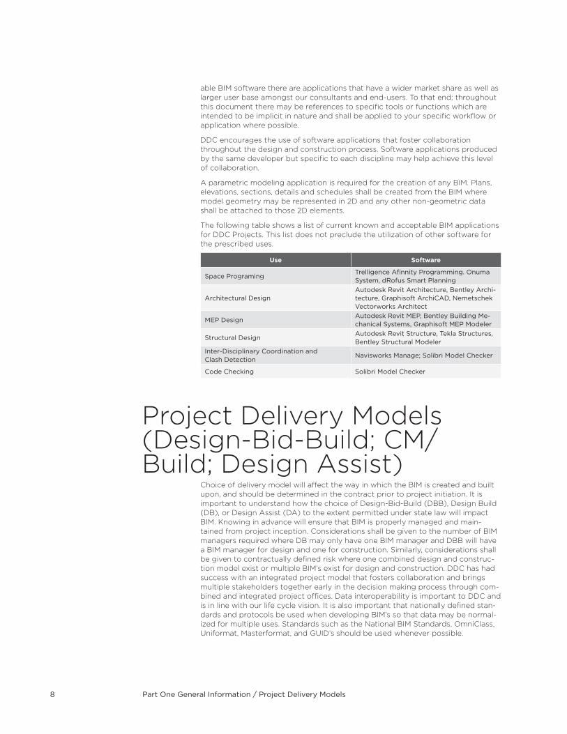
The following table shows a list of current known and acceptable BIM applications for DDC Projects . This list does not preclude the utilization of other software for the prescribed uses .
Use software
Space ProgramingTrelligence Afinnity Programming. Onuma System, dRofus Smart Planning
Architectural DesignAutodesk Revit Architecture, Bentley Archi-tecture, Graphisoft ArchiCAD, Nemetschek Vectorworks Architect
MEP DesignAutodesk Revit MEP, Bentley Building Me-chanical Systems, Graphisoft MEP Modeler
Structural DesignAutodesk Revit Structure, Tekla Structures, Bentley Structural Modeler
Inter-Disciplinary Coordination and Clash Detection
Navisworks Manage; Solibri Model Checker
Code Checking Solibri Model Checker
Project Delivery Models (Design-Bid-Build; CM/Build; Design Assist)
Choice of delivery model will affect the way in which the BIM is created and built upon, and should be determined in the contract prior to project initiation . It is important to understand how the choice of Design-Bid-Build (DBB), Design Build (DB), or Design Assist (DA) to the extent permitted under state law will impact BIM . Knowing in advance will ensure that BIM is properly managed and main-tained from project inception . Considerations shall be given to the number of BIM managers required where DB may only have one BIM manager and DBB will have a BIM manager for design and one for construction . Similarly, considerations shall be given to contractually defined risk where one combined design and construc-tion model exist or multiple BIM’s exist for design and construction . DDC has had success with an integrated project model that fosters collaboration and brings multiple stakeholders together early in the decision making process through com-bined and integrated project offices . Data interoperability is important to DDC and is in line with our life cycle vision . It is also important that nationally defined stan-dards and protocols be used when developing BIM’s so that data may be normal-ized for multiple uses . Standards such as the National BIM Standards, OmniClass, Uniformat, Masterformat, and GUID’s should be used whenever possible .
Part One General Information / Model Ownership 9
Model OwnershipDDC holds ownership of the BIMs including all inventions, ideas, designs, and methods contained within the model . This includes, but is not limited to; the con-tent submitted as part of the BIMs itself .
Outside resources, such as consultants and/or contractors, using the BIM are granted temporary use of it for the duration of the project . After project comple-tion they are required to return all copies of the BIM to the DDC .
DDC holds ownership of all the contents within the models from project concep-tion (pre-schematic design) all the way to completion (construction)
BIM Roles and Responsibilities
This section describes the BIM Roles and Responsibilities of the Team Members involved in DDC Projects . These Roles and Responsibilities may vary depend-ing on the Project Delivery Model and specific project conditions . At a minimum these roles and responsibilities must be met on all DDC BIM projects, any further consideration or elaboration on these roles and responsibilities will be included in the BIM Execution Plan (BEP)
BIM ManagerA BIM manager shall serve as the key point of contact with the DDC for all BIM related activity on a project . Individuals in this role will have the necessary ex-perience for the successful implementation of BIM in regards to the scope and complexity of any given project . In addition this individual shall have Intermediate knowledge and skills in the use of the proposed BIM authoring application as well as significant experience in the overall BIM process and ancillary tools .
In general, minimum responsibilities shall include the following:
Assures development and compliance with DDC BEP
Maintains and ensures adherence to the DDC - BIM Guidelines Manual
Overall responsibility for the proper use, implementation, and creation of BIM during design or construction
Manage and maintain the creation of all BIM content
Coordinate and Manage BIM related meetings with lead BIM technicians
Interface with IT managers to ensure proper hardware and software is in place and functioning properly
Provides specifications for BIM coordination rooms including necessary hardware and software for proper use
Facilitates use of correct models and assures the proper compilation of multiple models in support of necessary BIM uses
Manages coordination process, provides reports with the identification and or resolution of hard and soft conflicts
Facilitates the proper export and data extraction from the BIM as re-quested and in support of specific BIM uses
Assures proper deliverables are met and provided in formats as specified
Coordinates BIM training as required
Part One General Information / Discipline Trade BIM Coordinators10
Discipline Trade BIM Coordinators
A Discipline Trade BIM Coordinator shall serve as the lead BIM technician within their discipline or trade . Individuals in this role will have the necessary experience for the successful implementation of BIM specific to their profes-sion or trade . In addition, this individual shall be responsible for coordinating his or her work with the rest of the design or construction team .
In general, minimum responsibilities shall include the following:
Coordinates all technical discipline and trade specific BIM activity with BIM manager . Tools, Content, Standards, Requirements
Manage other BIM Users within the Discipline
Coordinate any BIM related issues with the rest of their Discipline Team
Supports team in the use of BIM tools
Create discipline specific BIM content
Coordinate discipline specific clash detection and resolution activities
Export the Model for Inter-Disciplinary Clash Detection .
Coordinates BIM training as required .
BIM Execution PlanThe DDC requires a BIM Execution Plan (BEP) within 30 days of project award and registration . The BEP shall align with the specific project delivery model for the project .
The intent of the BIM Execution Plan is to provide a framework that will let all the parties involved use and take advantage of BIM technology, along with best prac-tices and procedures aligned with the DDC BIM Guidelines, to ensure the project is complete on time and with minimum design and or coordination problems .
DEsCRIPTIOnThe BIM Execution Plan (BEP) is a detailed plan that defines how the proj-ect will be executed, monitored and controlled with regard to BIM . It is re-quired that a BEP be developed to provide a master information and data management plan and assignment of role and responsibilities for model creation and data integration at project initiation . The Plan shall incorpo-rate requirements specified for a project and will be developed through a collaborative approach involving all stakeholders .
The BEP will outline the project procurement strategy and will align to suit the needs of DBB, DB, DA, and DDC’s Integrated Delivery Strategy . Aspects of the BEP shall focus on Team Skills, Industry Capability, and improvements in technology . Through this collaborative process the team shall agree on how, when, why, and to what Level of Development (LOD) BIM shall be used in support of project outcomes and objectives . Depend-ing on the procurement strategy, multiple BEP’s may be needed . For ex-ample, in the case of Design-Bid-Build, one shall be provided during design and one during construction . For an Integrated Project, one BEP may be sufficient for the entire duration of the project .
Part Two BIM Use and Requirements / BIM Uses 11
PART TWO BIM UsE AnD REQUIREMEnTs
BIM Uses The nature of BIM technology allows different stakeholders to use the BIM in mul-tiple ways depending on the specific needs they may have . As the project moves from phase to phase, the information contained within the BIM shall evolve in a progressive manner .
The following list of BIM uses are the most common applications of BIM on DDC projects . BIM uses shall be considered and aligned with project goals and selected based on added value . BIM use shall be assessed and recorded in the DDC BEP .
One single BIM may perform multiple BIM uses . Therefore, the DDC is not expect-ing one model per each use described below .
EXIsTInG COnDITIOns MODELInG A process in which a project team develops a 3D Model of the existing conditions of a facility . This model can be developed in multiple ways depending on what is desired and what is most efficient . Once the model is constructed, it can be queried for information, whether it is for new con-struction or a modernization project .
The value of Existing Conditions Modeling is:
Document existing building for historical use
Provide documentation of environment for future uses
Enhance efficiency and accuracy of existing conditions documentation
Provide location information
Aids in future modeling and 3D design coordination
Use for visualization purposes
Laser scanningA process in which a laser beam is used to rapidly capture existing condi-tions of a building (interiors and/or exteriors) and/or natural environments (landscape) through equipment capable of measuring every point at a specific distance, speeding up the process of traditional data collection techniques and reducing errors and omissions .
Consultants using this technology will be responsible for processing this information and incorporating it back into the BIM as existing conditions . This process can be outlined in the BEP and will be reviewed by DDC’s Site Engineering Laser Scanning group .
sITE AnALYsIsA process in which BIM and or GIS tools are used to evaluate properties in a given area to determine the most optimal site location for a future proj-ect . The site data collected is used to first select the site and then position the building based on other criteria .
The value of Site Analysis is:
Use calculated decision making to determine if potential sites meet the required criteria according to the project requirements, technical factors, and financial factors
Decrease costs of utility demand and demolition
Increase energy efficiency
Part Two BIM Use and Requirements / BIM Uses12
Minimize risk of hazardous material
Maximize return on investment
PROGRAMMInGA process in which a spatial program is used to efficiently and accurately assess design performance in regard to spatial requirements . The devel-oped BIM allows the project team to analyze space and understand the complexity of space standards and regulations . Critical decisions are made in this phase of design and bring the most value to the project when needs and options are discussed with the client and the best approach is analyzed .
The value of Programming is:
Efficient and accurate assessment of design performance in re-gard to spatial requirements by the owner
EnGInEERInG AnALYsIsA process in which intelligent modeling software uses the BIM to deter-mine the most effective engineering method based on design specifica-tions . Development of this information is the basis for what will be passed on to the owner and/or operator for use in the building’s systems . These analysis tools and performance simulations can significantly improve the design of the facility and its energy consumption during its lifecycle in the future .
The value of Engineering Analysis is:
Achieve optimum, energy-efficient design solution by applying various rigorous analyses
Faster return on investment with applying audit and analysis tools for engineering analyses
Improve the quality and reduce the cycle time of the design analyses
DEsIGn AUTHORInGA process in which 3D software is used to develop a Building Information Model based on criteria that is important to the development of the build-ing’s design . Design authoring tools are a first step towards BIM and the key is connecting the 3D model with a powerful database of properties, quantities, means and methods, costs and schedules .
The value of Design Authoring is:
Transparency of design for all stakeholders
Better control and quality control of design, cost and schedule
Powerful design visualization
True collaboration between project stakeholders and BIM users
Improved quality control and assurance
sUsTAInABILITY (LEED) EVALUATIOnA process in which a project is evaluated based on LEED or other sustain-able criteria . This can refer to materials, performance, or a process . Sustain-ability Evaluations can be applied across all four phases of a construction project, Planning, Design, Construction, and Operation . Sustainability evaluation is most effective when it is done in planning and design stages and then applied in the construction and operations phase . Model all sustainable aspects of a project throughout its life-cycle in order to obtain the desired LEED certification in the most efficient manner by condensing design analyses into a single database .
Part Two BIM Use and Requirements / BIM Uses 13
The value of Sustainability (LEED) Evaluation is:
Accelerate design review and LEED certification process with efficient use of a single database with all the sustainable features present and archived
Improved communication between project participants in order to achieve LEED credits and decreased redesign efforts as a result
Align scheduling and material quantities tracking for more ef-ficient material use and better cash flow analysis
Optimize building performance by tracking energy use, indoor air quality and space planning for the adherence to LEED standards leading to integrated facility management using a BIM model
DEsIGn REVIEWA process in which a 3D model is used to evaluate meeting the program and set criteria such as layout, sightlines, lighting, security, ergonomics, acoustics, textures and colors . Virtual mock-ups can be done in high detail to quickly analyze design alternatives and solve design and con-structability issues .
The value of Design Review is:
Eliminate costly and timely traditional construction mock-ups
Model different design options and alternatives in real-time during design review by end users or owner
Create shorter and more efficient design reviews
Resolve the conflicts that would otherwise only become apparent in a mock-up and model the potential fixes in real-time along with tolerances revised and RFI’s answered
Preview space aesthetics and layout during design review in a virtual environment
Evaluate effectiveness of design in meeting building program criteria and owner’s needs
Easily communicate the design to the owner, construction team and end users . Get instant feedback on meeting program require-ments, owner’s needs and building or space aesthetics
CODE VALIDATIOnA process in which code validation software is utilized to check the model parameters against project specific codes .
The value of Code Validation is:
Validate that building design is in compliance with specific codes (IBC International Building Code, ADA Americans with Disabilities Act guidelines and other project related codes using the 3D BIM) .
Code validation done early in design reduces the chance of code design errors, omissions or oversights that would be time consum-ing and more expensive to correct later in design or construction
Code validation done automatically while design progresses gives continuous feedback on code compliance
CLAsH DETECTIOnA process in which clash detection software is used during the coordi-nation process to determine field conflicts by comparing 3D models of building systems . The goal of clash detection is to eliminate major system conflicts prior to installation .
Part Two BIM Use and Requirements / BIM Uses14
The value of Clash Detection is:
Reduce and eliminate field conflicts; which reduces RFI’s signifi-cantly compared to other methods
Visualize construction sequences, staging and logistics
Reduced construction cost; potentially less cost growth (less change orders)
Decrease construction time
Increase productivity on site
More accurate as built drawings
COsT EsTIMATIOnA process in which the BIM can be used to generate an accurate quantity take-off and cost estimate early in the design process and provide cost ef-fects of additions and modifications with potential to save time and money and avoid budget overruns . This process also allows designers to see the cost effects of their changes in a timely manner which can help curb exces-sive budget overruns due to project modifications .
The value of Cost Estimation is:
Precisely estimate material quantities and generate quick revisions if needed
Stay within budget constraints while the design progresses
Better visual representation of project and construction elements that need to be estimated
Provide cost information to the owner during the early decision making phase of design
Focus on more value adding activities in estimating (identifying construction assemblies, generating pricing and factoring risks) which are essential for high-quality estimates
Exploring different design options and concepts within the owner’s budget
Saving estimator’s time and allowing them to focus on more important issues in an estimate since take-offs can be automati-cally provided
COnsTRUCTIOn sYsTEM DEsIGn A process in which 3D system design software is used to design and analyze the construction of a complex building system (form work, glazing, tie-backs) .
The value of Construction System Design is:
Ensure constructability of a complex building system
Increase construction productivity
Increase safety awareness of a complex building system
Increase Communication
PHAsE PLAnnInGA process in which BIM is utilized to effectively plan the phased occupancy in a renovation, retrofit, addition, or to show the construction sequence and space requirements on a building site . 4D modeling is a powerful visualization and communication tool that can give a project team, includ-ing the owner, a better understanding of project milestones and construc-tion plans .
Part Two BIM Use and Requirements / BIM Uses 15
The value of Phase Planning is:
Better understanding of the phasing schedule by the owner and project participants and showing the critical path of the project
Dynamic phasing plans of occupancy offering multiple options and solutions to space conflicts
Integrate planning of human, equipment and material resources with the BIM model to better schedule and cost estimate the project
Space and workspace conflicts identified and resolved ahead of the construction process
Marketing purposes and publicity
Identification of schedule, sequencing or phasing issues
More readily constructible, operable and maintainable project
Monitor procurement status of project materials
Increased productivity and decreased waste on job sites
Conveying the spatial complexities of the project, planning infor-mation, and support conducting additional analyses
DIGITAL FABRICATIOnA process that utilizes machine technology to prefabricate objects directly from a BIM . The Model is spooled into appropriate sections and input into fabrication equipment for production of system assemblies .
The value of Digital Fabrication is:
Automate building component fabrication
Minimize tolerances through machine fabrication
Maximize fabrication productivity
RECORD MODELInGA process used to depict an accurate representation of the physical condi-tions, environment, and assets of a facility . The record model should, at a minimum, contain information relating to the main architectural and MEP elements . Additional information including equipment and space planning systems may be necessary if the owner intends to utilize the information for maintenance and operations .
With the continuous updating and improvement of the record model and the capability to store more information, the record model contains a true depiction of space with a link to information such as serial codes, warran-ties and maintenance history of all the components in the building . The record model also contains information linking pre-build specification to as-built specifications . This allows the owner to monitor the project relative to the specifications provided .
The value of Record Modeling is:
Aid in future modeling and 3D design coordination for renovation
Provide documentation of environment for future uses, e .g ., reno-vation or historical documentation
Dispute elimination (for example, a link to contract with histori-cal data highlights expectations and comparisons drawn to final product .)
Solid understanding of project sequencing by stakeholders leads to reduced project delivery times, risk, cost, and lawsuits
Part Two BIM Use and Requirements / Parametric Modeling16
AssET MAnAGEMEnTA process in which an organized management system will efficiently aid in the maintenance and operation of a facility and its assets . These assets, consisting of the physical building, systems, surrounding environment, and equipment, must be maintained, operated, and upgraded at an effi-ciency which will satisfy both the owner and users at the lowest appropri-ate cost . It assists in financial decision making, as well as short-term and long-term planning . Asset Management utilizes the data contained in a record model to determine cost implications of changing or upgrading building assets, segregate costs of assets for financial tax purposes, and maintain a current comprehensive database that can produce the value of a company’s assets .
The value of Asset Management is:
Store operations, maintenance owner user manuals, and equipment specifications
Perform and analyze facility and equipment condition assessments
Maintain up-to-date facility and equipment data including, but not limited to, maintenance schedules, warranties, cost data, upgrades, replacements, damages/deterioration, maintenance records, manufacturer’s data, equipment functionality, and others required by owner
Provide one comprehensive source for tracking the use, performance, and maintenance of a building’s assets for the owner, maintenance team, and financial department
Produce accurate inventory of current company assets which aids in financial reporting, bidding, and estimating the future cost implications of upgrades or replacements of a particular asset
Allow for future updates of record model to show current building asset information after upgrades, replacements, or maintenance by tracking changes
Aid financial department in efficiently analyzing different types of assets through an increased level of visualization
Increase the opportunity for measurement and verification of systems during building occupation
Parametric ModelingTo allow the different BIM Uses described in the BIM Uses section, Parametric Modeling is to be used on all DDC BIM Projects . Parametric Modeling is character-ized by designing with objects having real-world behaviors and attributes, using parameters (numbers or characteristics) to determine the behavior of a graphical entity and define relationships between model components .
A parametric modeling application is required for the creation of any BIM . Plans, elevations, sections, details, and schedules shall be created from the BIM where model geometry may be represented in 2D and any other non-geometric data shall be attached to those 2D elements .
NOTE: The integrity of the Model should not be compromised to reflect the 2D represen-tation of 3D elements contained within the BIM .
To ensure consistency, all models and parts of models designed though analysis, shop drawing or any other non-parametric application must be integrated back into the design or construction models at each submission .
Part Two BIM Use and Requirements / Model Discrepancies 17
Model DiscrepanciesWhen conflicts exist between the contents of a BIM and the Contract Set of Drawings, the information contained within the Contract Set will prevail and will be considered as definitive . The BIM shall still contain accurate representations of the design condition regardless of what is displayed on the drawing set .
Uniformat Classification and Omniclass
DDC BIM Guidelines organizes all of its assets based on the Uniformat System (CSI Uniformat 2004 Classification) and with the OmniClass System (OmniClass Construction Classification System) . These classification systems organize all the different building elements into specific groups .
The CSI Release 2010 Edition of UniFormat and the 2010 OmniClass Tables should be used as a reference when classifying Objects within the BIM .
Coordinate SystemIn an effort to organize, consolidate and standardize the information generated and consumed by all Design Disciplines within the DDC, BIM projects shall use NY State Plane NAD83(NA2011) Epoch 2010 .00 Long Island zone unless otherwise dictated .
Model ContinuityDDC requires that all BIMs shall be developed using object-based elements only, such as Columns, Beams, Walls, Doors, Windows, etc . along with their associated parametric information . This will ensure continuity of the BIM process from Con-ceptual Design through Construction . As well, provide a foundation for the owner of the facility to expand the model for operations and maintenance .
Model Level of Development
The Model Level of Development (LOD) describes the level of detail to which a Model is developed and its minimum requirements . The Level of Development is accumulative and should progress from LOD 100 at Conceptual Design through LOD 400 at completion of Construction .
The DDC Level of Development has been developed in alignment with the AIA – Exhibit E202 Document .
Part Two BIM Use and Requirements / Model Level of Development18
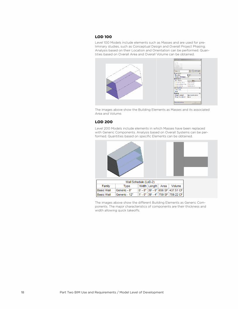
LOD 100Level 100 Models include elements such as Masses and are used for pre-liminary studies, such as Conceptual Design and Overall Project Phasing . Analysis based on their Location and Orientation can be performed . Quan-tities based on Overall Area and Overall Volume can be obtained .
The images above show the Building Elements as Masses and its associated Area and Volume .
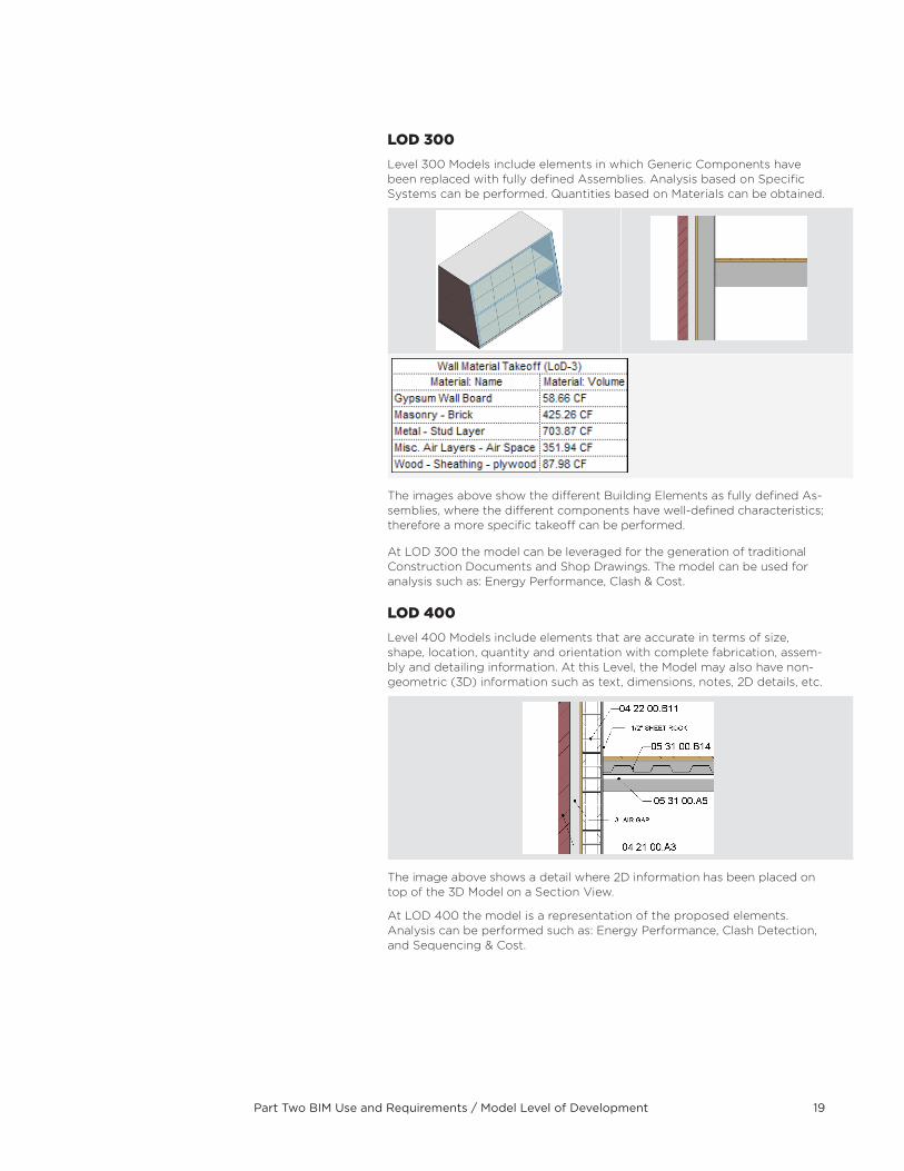
LOD 200Level 200 Models include elements in which Masses have been replaced with Generic Components . Analysis based on Overall Systems can be per-formed . Quantities based on specifi c Elements can be obtained .
The images above show the diff erent Building Elements as Generic Com-ponents . The major characteristics of components are their thickness and width allowing quick takeoff s .
Part Two BIM Use and Requirements / Model Level of Development 19
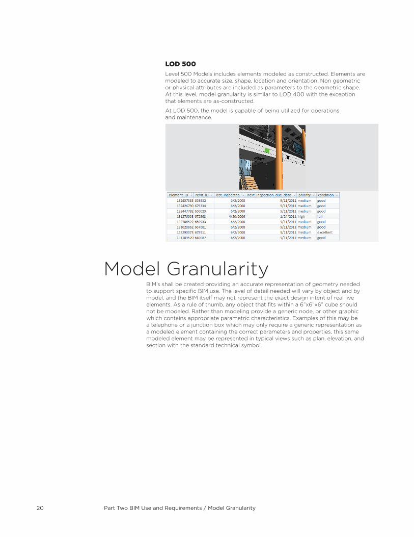
LOD 300Level 300 Models include elements in which Generic Components have been replaced with fully defined Assemblies . Analysis based on Specific Systems can be performed . Quantities based on Materials can be obtained .
The images above show the different Building Elements as fully defined As-semblies, where the different components have well-defined characteristics; therefore a more specific takeoff can be performed .
At LOD 300 the model can be leveraged for the generation of traditional Construction Documents and Shop Drawings . The model can be used for analysis such as: Energy Performance, Clash & Cost .
LOD 400Level 400 Models include elements that are accurate in terms of size, shape, location, quantity and orientation with complete fabrication, assem-bly and detailing information . At this Level, the Model may also have non-geometric (3D) information such as text, dimensions, notes, 2D details, etc .
The image above shows a detail where 2D information has been placed on top of the 3D Model on a Section View .
At LOD 400 the model is a representation of the proposed elements . Analysis can be performed such as: Energy Performance, Clash Detection, and Sequencing & Cost .
Part Two BIM Use and Requirements / Model Granularity20
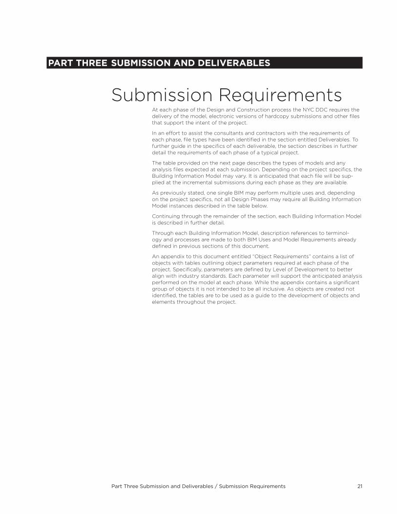
LOD 500Level 500 Models includes elements modeled as constructed . Elements are modeled to accurate size, shape, location and orientation . Non geometric or physical attributes are included as parameters to the geometric shape . At this level, model granularity is similar to LOD 400 with the exception that elements are as-constructed .
At LOD 500, the model is capable of being utilized for operations and maintenance .
Model GranularityBIM’s shall be created providing an accurate representation of geometry needed to support specific BIM use . The level of detail needed will vary by object and by model, and the BIM itself may not represent the exact design intent of real live elements . As a rule of thumb, any object that fits within a 6”x6”x6” cube should not be modeled . Rather than modeling provide a generic node, or other graphic which contains appropriate parametric characteristics . Examples of this may be a telephone or a junction box which may only require a generic representation as a modeled element containing the correct parameters and properties, this same modeled element may be represented in typical views such as plan, elevation, and section with the standard technical symbol .
Part Three Submission and Deliverables / Submission Requirements 21
PART THREE sUBMIssIOn AnD DELIVERABLEs
Submission Requirements At each phase of the Design and Construction process the NYC DDC requires the delivery of the model, electronic versions of hardcopy submissions and other files that support the intent of the project .
In an effort to assist the consultants and contractors with the requirements of each phase, file types have been identified in the section entitled Deliverables . To further guide in the specifics of each deliverable, the section describes in further detail the requirements of each phase of a typical project .
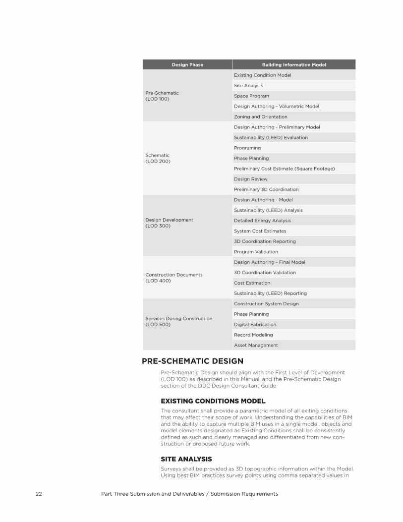
The table provided on the next page describes the types of models and any analysis files expected at each submission . Depending on the project specifics, the Building Information Model may vary . It is anticipated that each file will be sup-plied at the incremental submissions during each phase as they are available .
As previously stated, one single BIM may perform multiple uses and, depending on the project specifics, not all Design Phases may require all Building Information Model instances described in the table below .
Continuing through the remainder of the section, each Building Information Model is described in further detail .
Through each Building Information Model, description references to terminol-ogy and processes are made to both BIM Uses and Model Requirements already defined in previous sections of this document .
An appendix to this document entitled “Object Requirements” contains a list of objects with tables outlining object parameters required at each phase of the project . Specifically, parameters are defined by Level of Development to better align with industry standards . Each parameter will support the anticipated analysis performed on the model at each phase . While the appendix contains a significant group of objects it is not intended to be all inclusive . As objects are created not identified, the tables are to be used as a guide to the development of objects and elements throughout the project .
Part Three Submission and Deliverables / Submission Requirements 22
Design Phase Building Information Model
Pre-Schematic(LOD 100)
Existing Condition Model
Site Analysis
Space Program
Design Authoring - Volumetric Model
Zoning and Orientation
Schematic(LOD 200)
Design Authoring - Preliminary Model
Sustainability (LEED) Evaluation
Programing
Phase Planning
Preliminary Cost Estimate (Square Footage)
Design Review
Preliminary 3D Coordination
Design Development(LOD 300)
Design Authoring - Model
Sustainability (LEED) Analysis
Detailed Energy Analysis
System Cost Estimates
3D Coordination Reporting
Program Validation
Construction Documents(LOD 400)
Design Authoring - Final Model
3D Coordination Validation
Cost Estimation
Sustainability (LEED) Reporting
Services During Construction(LOD 500)
Construction System Design
Phase Planning
Digital Fabrication
Record Modeling
Asset Management
PRE-sCHEMATIC DEsIGnPre-Schematic Design should align with the First Level of Development (LOD 100) as described in this Manual, and the Pre-Schematic Design section of the DDC Design Consultant Guide
eXisTing cOnDiTiOns MODeLThe consultant shall provide a parametric model of all exiting conditions that may affect their scope of work . Understanding the capabilities of BIM and the ability to capture multiple BIM uses in a single model, objects and model elements designated as Existing Conditions shall be consistently defined as such and clearly managed and differentiated from new con-struction or proposed future work .
siTe anaLYsisSurveys shall be provided as 3D topographic information within the Model . Using best BIM practices survey points using comma separated values in
Part Three Submission and Deliverables / Submission Requirements 23
.txt format or points available in other CAD applications shall be imported and used as the basis to develop topography .
Additional information might be provided as 2D elements as long as they are not required for the project specifics or they are used as a reference only .
sPace PrOgraMWhere the consultant is developing a space program for the project, the space program shall be able too seamlessly integrate with the BIM applica-tion in use during the schematic design phase, as well as be imported and further developed in any DDC approved space programming application .
Design aUTHOring - VOLUMeTric MODeLThe Volumetric Model shall be defined as masses based on the information gathered from the Site and should define the building footprint . This model should be the basis of what will be developed in future phases .
As the Model evolves, the Design Authoring – Volumetric Model should include:
Building function and occupancy Building location Building HVAC equipment information (EER, COP, MBH, kW, tons, etc .)
Building envelope construction components including U-values, SHGC, absorptivity, SRI value, color, thickness, etc .
ZOning & OrienTaTiOnThe Volumetric Model shall be used in support of an early decision making process for building location and orientation within the property line .
The purpose of these simulations is to inform early design decisions with reference to building envelope, lighting, domestic water, and HVAC sys-tems . Multiple energy simulation iterations shall be performed by changing one component at a time and comparing those results to the results of other iterations in a “percent better” or “percent worse” scenario .
Design components that present “percent better” that are in line with the project energy goals will then be developed further in the schematic (criteria) design phase .
sCHEMATIC DEsIGnSchematic Design must align with the Second Level of Development (LOD 200) as described in this Manual and the Schematic Design Section of the DDC Design Consultant Guide .
Design aUTHOring - PreLiMinarY MODeLThe Preliminary Model shall at least include the following generic elements to ensure the appropriate effort within this phase . Refer to Object Require-ments in the appendix for a detailed description of each of these Objects .
Site Model• ExistingConditions• Topography
Architecture• InteriorandExteriorWalls• DoorsandWindows• StairandRamps• Ceilings• Roofs• BoundedRoomswithNamesandNumbers
Structure Foundations
Part Three Submission and Deliverables / Submission Requirements 24
Columns Beams Bracing Floors Mechanical Equipment Main Duct Lines Fire Protection Equipment Main Pipe Lines Plumbing Equipment and Fixtures Main Pipe Lines Electrical Panels and Fixtures Main Conduit Lines Electronics Panels and Fixtures Main Conduit Lines
sUsTainaBiLiTY (LeeD) eVaLUaTiOnAll aspects of sustainability should be considered at this stage in order to evaluate the LEED criteria of materials, performance, and processes . Building performance should be optimized by tracking energy use, indoor air quality and space planning for the adherence to LEED standards . LEED goals should be established at this stage and strategies for evaluating, tracking, and documenting LEED within the BIM shall be implemented .
PrOgraMMingDuring this phase a space program is expected to be incorporated into the BIM . The creation of this data can support the design team in program vali-dation, program reporting and tracking . A space programming application may be used to achieve this requirement where customized reports may be produced . All program data in support of the space program regardless of where it derived shall be updated and maintained in the BIM .
The following shall be derived automatically from the BIM: Program Function Room Name Room Number Assignable Areas measured to inside face of wall objects and designated boundaries of areas
Gross Area measured to the outside face of wall objects
PHase PLanningDesign phases should be defined at this stage and shall be consistent throughout all the different project models for proper coordination . Design phases shall be implemented using a tool or a parameter to define or categorize all elements contained within the BIM .
PreLiMinarY cOsT esTiMaTe (sQUare FOOTage)Extract square foot information directly from the BIM integrated tools to support comparative costs analysis of options studied . Outputs shall be converted to spreadsheets and submitted as part of the design solution justification at end of this phase .
A summary of construction cost per trade is expected at this stage
Design reVieWA detailed Design Review is critical at this stage since the Model will be de-veloped further once it’s moved to the next stage . Program evaluation and layout design, lighting, acoustics, textures and colors should be considered as part of the review .
Part Three Submission and Deliverables / Submission Requirements 25
PreLiMinarY cLasH DeTecTiOnPreliminary coordination at this stage should, at a minimum, be performed within the major systems on these pairs of elements:
Architectural Systems vs . Structural Systems Architectural Systems vs . Mechanical Systems Architectural Systems vs . Electrical Systems Structural Systems vs . Mechanical Systems Structural Systems vs . Electrical Systems Mechanical Systems vs . Electrical Systems
DEsIGn DEVELOPMEnTDesign Development must align with the Third Level of Development (LOD 300) as described in this Manual, and the Design Development section of the DDC Design Consultant Guide .
All systems shall be defined at this stage with the appropriate shapes and sizes along with the proper documentation to support the analysis . Listed below are defined systems with the most common elements defined for each . The list is not intended to be all inclusive, but rather a foundation to build upon .
Design aUTHOring – MODeLsThe Model will evolve from the previous phase and shall include better defined elements to ensure the appropriate effort within this phase . Refer to the Object Requirements in the appendix for a detailed description of each of these Objects .
Additional elements and objects may need to be added from the previous stage Design Authoring - Preliminary Model to represent new features of the project .
sUsTainaBiLiTY (LeeD) anaLYsisThis model shall be detailed and finalized enough to use as an indicator of approximate building energy use after occupancy . This model shall also serve as a baseline for future comparisons .
Custom parameters may be created to associate LEED information to the different elements within the BIM .
This model shall be used as a tool to facilitate post-occupancy commission-ing should discrepancies between modeled and actual energy use arise .
cOsT esTiMaTiOnAll elements or objects included within the Model should be automatically extracted and quantified for estimating purposes .
cLasH DeTecTiOnCoordination at this stage should be performed within the major and minor systems based on these pair of elements:
Architectural Systems vs . Structural Systems Architectural Systems vs . HVAC Systems Architectural Systems vs . Plumbing Systems Architectural Systems vs . Fire Protection Systems Architectural Systems vs . Electrical Systems Architectural Systems vs . Electronics Systems Structural Systems vs . HVAC Systems Structural Systems vs . Plumbing Systems Structural Systems vs . Fire Protection Systems Structural Systems vs . Electrical Systems Structural Systems vs . Electronics Systems HVAC Systems vs . Plumbing Systems
Part Three Submission and Deliverables / Submission Requirements 26
HVAC Systems vs . Fire Protection Systems HVAC Systems vs . Electrical Systems HVAC Systems vs . Electronics Systems Plumbing Systems vs . Fire Protection Systems Plumbing Systems vs . Electrical Systems Plumbing Systems vs . Electronics Systems Fire Protection Systems vs . Electrical Systems Fire Protection Systems vs . Electronics Systems
PrOgraM VaLiDaTiOnProgram requirements should be compared and validated with the actual de-sign solution through reports and charts generated automatically from the BIM .
COnsTRUCTIOn DOCUMEnTsConstruction Documents should align with the Fourth Level of Develop-ment (LOD 400) as described in this Manual . This model should include the current design models from each phase through the end of Design Development .
Design aUTHOring - FinaL MODeLThe Model will keep evolving from the previous phase and shall include construction specifications along with constructions details including text, dimensions, tags, notes, materials, colors and any other description or characteristic required for construction .
As previously stated, the integrity of the Model should not be compromised to reflect the 2D representation of 3D elements contained within the BIM .
3D cOOrDinaTiOn VaLiDaTiOn3D coordination validation should evolve from the previous phase . All conflicts previously found should be resolved at the end of this phase by running a final Clash Detection Report to validate the absence of Conflicts .
cOsT esTiMaTiOnQuantity takeoffs should be automatically extracted from the model . Cost should be validated by integrating applications with Quantity tools or exported as spreadsheets for traditional methods .
sUsTainaBiLiTY (LeeD) rePOrTingAll LEED documentation and reports should be completed at this stage and should be ready to be submitted as part of the project deliverables .
These documents and reports will use the previously defined custom pa-rameters in which LEED information have been associated to the different elements within the BIM .
BID, AWARD AnD REGIsTRATIOnServices during BID, Award and Registeration should align with the Fourth Level of Development (LOD 400) as described in this manual, and the BID Award and Registration section of the DDC Design Consultant Guide . After completion and approval of the 100% construction document phase, design intent BIM’s shall be archived and provided to the DDC . (see de-liverables section of this guide) All deliverables including Archived BIM’s, hardcopies, dwf’s and pdf’s derived from such BIM’s shall be indentical to the desired design conditions at the time bids are received .
During the Bidding phases through Award and Registration the model may be provided for informational purposes . Refer to the project specific RFP and the DDC BEP for BIM use and model availablility .
Part Three Submission and Deliverables / Submission Requirements 27
sERVICEs DURInG COnsTRUCTIOnServices during Construction should align with the Fifth Level of Devel-opment (LOD 500) as described in this Manual, and the Services during construction section of the DDC Design Consultant Guide . The design BIM will be provided by the owner in its native authored format along with an assembled BIM in a format appropriate for collaboration (Navisworks or equal see deliverables section of this guide) . The Construction manager or the general construction contractor shall use the Design BIM as a basis for creating a construction model to achieve the desired BIM uses outlined in this section .
cOnsTrUcTiOn sYsTeM DesignThe BIM shall be used to better understand how complex element or elements of the project can get built on the site . These virtual mock-ups can be used to replace the on-site mock-ups and facilitate or expedite construction through tools that will allow linking the BIM sequencing, take offs, etc .
These virtual mock-ups will enable the trial of alternate options before construction begins allowing the contractor to select the best one that fits the project needs .
PHase PLanningPhases during Construction should be defined after the Design phase is completed and before the project is handed over for construction . Con-struction phases shall be implemented to improve constructability through the use of tools that will allow linking the BIM to a construction scheduling appllcation, such as Primavera and/or Microsoft Projects .
The BIM shall be used to analyze and perform construction sequencing to avoid conflicts once construction starts and therefore improve the constructability process .
scHeDULingDuring construction the BIM shall be utilized to facilitate activity sched-uling . Prior to construction the BIM shall be linked to the schedule by the CM and or GC for the purpose of 4d scheduling . Using applicable tools and applications elements or parts of the BIM shall be linked to the specific task in the schedule for the purpose of informing critical plan-ning decisions and construction methods, site space utilization, resource allocation, activity sequencing, visualization and communication . Primary elements of the model listed below shall be linked to the schedule to achieve desired results .
Structural system—structural framing components including foundations, grade beams, columns, load bearing walls, floor and roof decks and support .
Exterior building envelope—stud wall, exterior panels and assem-blies, curtain walls, openings, and glazing .
Interior partitions—main interior walls, plumbing walls, and wall assemblies .
Mechanical systems—main ductwork and equipment, separated by floors .
Roof systems—roof assemblies, major equipment, and openings . Site work—excavation work, footings, foundations, and slabs on grade .
Plumbing systems—main connection lines from site and main plumbing lines .
Additional considerations shall be made to specific construction activities and task where detailed construction planning is required such as virtual test installations and logistics planning . Linking the model to the schedule in these instances shall improve coordination
Part Three Submission and Deliverables / Submissions & Deliverables28
and parallel activity workflows reducing conflicts and delays by loca-tion and resource unavailability .
3D cOOrDinaTiOn 3D coordination is an on-going process which should start at the early stages of the Design phase and evolve and muture as the project progresses .
3D coordination will also happen during construction to assist and to sup-port the creation of the “as built” model once construction is completed so a conflict-free model can be provided for the operations and maintenance of the building .
DigiTaL FaBricaTiOnThe BIM can be used to extract information directly from it to streamline the pre-fabrication and/or fabrication of elements such as pipes, ducts, structural members, etc . A list of intended objects that will be part of this effort shall be defined at the Construction phase so they can be modeled using the characteristic defined within their construction specifications .
recOrD MODeLingAs construction progresses, the BIM shall be updated if changes occur on site due to conflicts and/or chagnes on scope, this way at the comple-tion of the project the BIM becomes the “as built” and can be leveraged beyond construction .
asseT ManageMenTThe “as built” BIM shall be leveraged to manage and operate the building once construction is completed, to that extent, the BIM shall include fields (parameters) to support this effort .
These fields may vary from project to project and may be different de-pending on the type of project as well, therefore, they should be defined and incorporated within the BIM at the Construction phase with the input of the people responsible for maintenance and operations .
Submissions & DeliverablesnOMEnCLATURE
This section establishes the basic naming conventions and standards required to be used when developing a project using BIM technology for DDC .
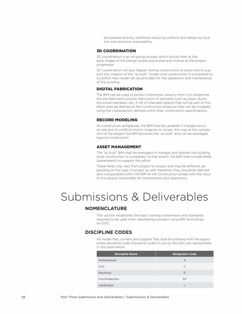
DIsCIPLInE CODEsAll model files, content and support files shall be prefixed with the appro-priate discipline code . Discipline codes in use by the DDC are represented in the table below .
Discipline name Designator Code
Architectural A
Civil C
Electrical E
Fire Protection FP
Landscape L
Part Three Submission and Deliverables / Submissions & Deliverables 29
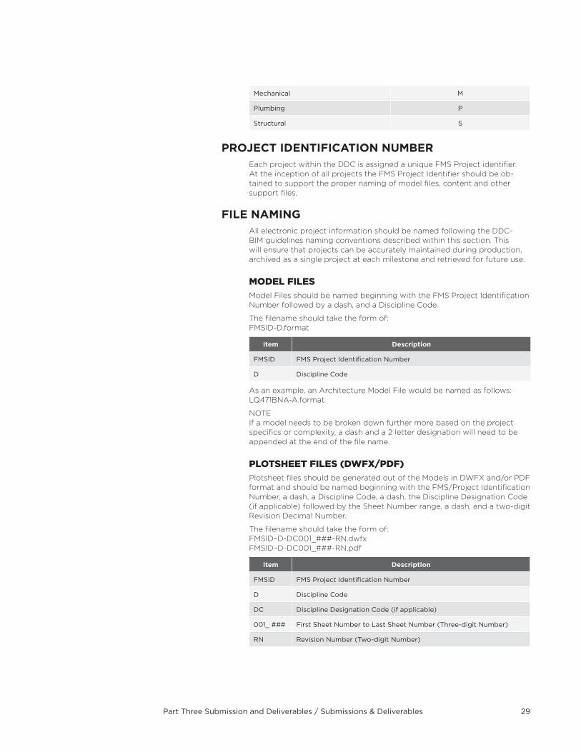
Mechanical M
Plumbing P
Structural S
PROjECT IDEnTIFICATIOn nUMBEREach project within the DDC is assigned a unique FMS Project identifier . At the inception of all projects the FMS Project Identifier should be ob-tained to support the proper naming of model files, content and other support files .
FILE nAMInGAll electronic project information should be named following the DDC- BIM guidelines naming conventions described within this section . This will ensure that projects can be accurately maintained during production, archived as a single project at each milestone and retrieved for future use .
MODeL FiLesModel Files should be named beginning with the FMS Project Identification Number followed by a dash, and a Discipline Code .
The filename should take the form of: FMSID-D .format
Item Description
FMSID FMS Project Identification Number
D Discipline Code
As an example, an Architecture Model File would be named as follows: LQ471BNA-A .format
NOTE If a model needs to be broken down further more based on the project specifics or complexity, a dash and a 2 letter designation will need to be appended at the end of the file name .
PLOTsHeeT FiLes (DWFX/PDF)Plotsheet files should be generated out of the Models in DWFX and/or PDF format and should be named beginning with the FMS/Project Identification Number, a dash, a Discipline Code, a dash, the Discipline Designation Code (if applicable) followed by the Sheet Number range, a dash, and a two-digit Revision Decimal Number .
The filename should take the form of: FMSID–D-DC001_###-RN .dwfx FMSID–D-DC001_###-RN .pdf
Item Description
FMSID FMS Project Identification Number
D Discipline Code
DC Discipline Designation Code (if applicable)
001_ ### First Sheet Number to Last Sheet Number (Three-digit Number)
RN Revision Number (Two-digit Number)
Part Three Submission and Deliverables / Submissions & Deliverables30
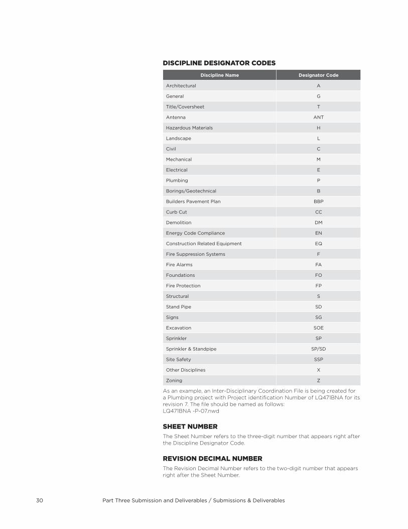
DisciPLine DesignaTOr cODes
Discipline name Designator Code
Architectural A
General G
Title/Coversheet T
Antenna ANT
Hazardous Materials H
Landscape L
Civil C
Mechanical M
Electrical E
Plumbing P
Borings/Geotechnical B
Builders Pavement Plan BBP
Curb Cut CC
Demolition DM
Energy Code Compliance EN
Construction Related Equipment EQ
Fire Suppression Systems F
Fire Alarms FA
Foundations FO
Fire Protection FP
Structural S
Stand Pipe SD
Signs SG
Excavation SOE
Sprinkler SP
Sprinkler & Standpipe SP/SD
Site Safety SSP
Other Disciplines X
Zoning Z
As an example, an Inter-Disciplinary Coordination File is being created for a Plumbing project with Project identification Number of LQ471BNA for its revision 7 . The file should be named as follows: LQ471BNA -P-07 .nwd
sHeeT nUMBerThe Sheet Number refers to the three-digit number that appears right after the Discipline Designator Code .
reVisiOn DeciMaL nUMBerThe Revision Decimal Number refers to the two-digit number that appears right after the Sheet Number .
Part Three Submission and Deliverables / Submissions & Deliverables 31
reVisiOnsWhen creating Plotsheet in DWFX or PDF format containing revisions, only consecutive sheets can be grouped together within the electronic files .
As an example, the Structural discipline is creating a revision 7 of sheets 001 through 007 and sheets 011 and 013 . Three files should be named as follows: LQ471BNA-S-001_007-07 LQ471BNA-S-011-07 LQ471BNA-S-013-07
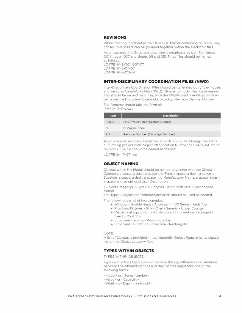
inTer-DisciPLinarY cOOrDinaTiOn FiLes (nWD)Inter-Disciplinary Coordination Files should be generated out of the Models and saved as NavisWorks files (NWD) . Similar to model files, coordination files should be named beginning with the FMS/Project Identification Num-ber, a dash, a Discipline Code and a two-digit Revision Decimal Number .
The filename should take the form of: FMSID–D- RN .nwd
Item Description
FMSID FMS/Project Identification Number
D Discipline Code
RN Revision Number (Two-digit Number)
As an example, an Inter-Disciplinary Coordination File is being created for a Plumbing project with Project identification Number of LQ471BNA for its revision 7 . The file should be named as follows:
LQ471BNA -P-07 .nwd
OBJecT naMingObjects within the Model should be named beginning with the Object Category, a space, a dash, a space, the Type, a space, a dash, a space, a Subtype, a space, a dash, a space, the Manufacturer Name, a space, a dash, a space and an optional User Description .
<Object Category>-<Type>-<Subtype>-<Manufacturer>-<Description> .format The Type, Subtype and Manufacturer fields should be used as needed .
The following is a list of five examples: Window - Double Hung - Andersen - 400 Series - Arch Top Plumbing Fixtures - Sink - Oval - Generic - Under Counter Mechanical Equipment - Air Handling Unit - Vertical Packaged - Sierra - Roof Top
Structural Framing - Wood - Lumber Structural Foundation - Concrete - Rectangular
NOTE: A list of Objects is provided in the Appendix . Object Requirements should match the Object category field .
TYPes WiTHin OBJecTsTYPES WITHIN OBJECTS
Types within the Objects should indicate the key differences or variations between the different options and their names might take one of the following forms:
<Model> or <Series Number> <Value> or <Capacity> <Width> x <Depth> x <Height>
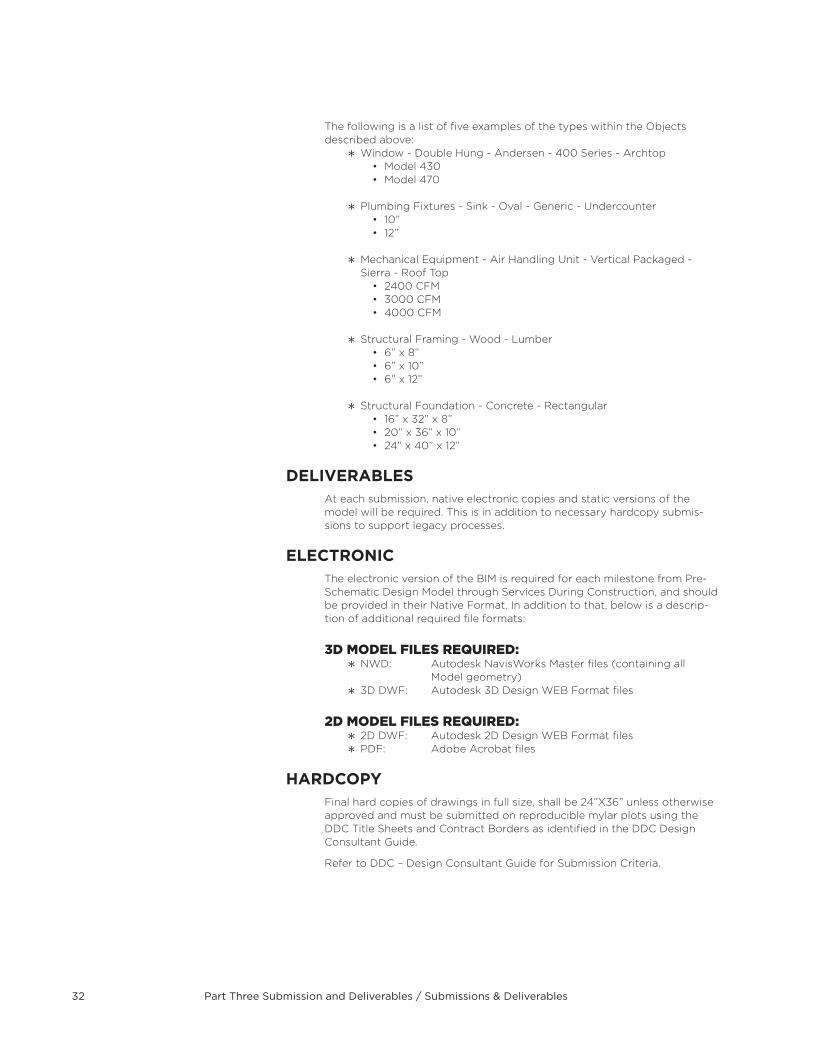
Part Three Submission and Deliverables / Submissions & Deliverables32
The following is a list of five examples of the types within the Objects described above:
Window - Double Hung - Andersen - 400 Series - Archtop• Model430• Model470
Plumbing Fixtures - Sink - Oval - Generic - Undercounter• 10”• 12”
Mechanical Equipment - Air Handling Unit - Vertical Packaged - Sierra - Roof Top• 2400CFM• 3000CFM• 4000CFM
Structural Framing - Wood - Lumber• 6”x8”• 6”x10”• 6”x12”
Structural Foundation - Concrete - Rectangular• 16”x32”x8”• 20”x36”x10”• 24”x40”x12”
DELIVERABLEsAt each submission, native electronic copies and static versions of the model will be required . This is in addition to necessary hardcopy submis-sions to support legacy processes .
ELECTROnICThe electronic version of the BIM is required for each milestone from Pre-Schematic Design Model through Services During Construction, and should be provided in their Native Format . In addition to that, below is a descrip-tion of additional required file formats:
3D MODeL FiLes reQUireD: NWD: Autodesk NavisWorks Master files (containing all
Model geometry) 3D DWF: Autodesk 3D Design WEB Format files
2D MODeL FiLes reQUireD: 2D DWF: Autodesk 2D Design WEB Format files PDF: Adobe Acrobat files
HARDCOPYFinal hard copies of drawings in full size, shall be 24”X36” unless otherwise approved and must be submitted on reproducible mylar plots using the DDC Title Sheets and Contract Borders as identified in the DDC Design Consultant Guide .
Refer to DDC – Design Consultant Guide for Submission Criteria .
Part Four Glossary and Appendix / Definitions 33
PART FOUR GLOssARY AnD APPEnDIX
Definitions3D MODEL
A three-dimensional representation of a building or structure generated out of a CAD or BIM application
BEPBIM Execution Plan (BEP) is an organized, documented approach to pro-viding a strategy for all parties involved in contributing to model, informa-tion, analysis or consumption of a project utilizing the BIM process .
BIMBuilding Information Modeling (BIM) is a process for managing a facility through its life-cycle . This extends from design to demolition . Typically, BIM starts with a three dimensional model with increasing levels of detail as to the functions it supports .
BUILDInG InFORMATIOn MODELA Building Information Model (BIM) is a digital representation of the physi-cal and functional characteristics of a building or structure
CAD/BIM MAnAGERThe System Administrator for all CAD & BIM projects responsible for the management of all CAD & BIM data and processes .
DWFA highly compressed non-editable vector file format created out of CAD/BIM applications . A DWF file can represent sheets for plotting purposes (2D DWF) or the entire 3D Model (3D DWF) for visualization or estimating purposes . DWF is short for Design Web Format, created by Autodesk .
DWGDWG (Drawing) is a binary file system licensed by Autodesk for the pur-pose of storing two and three dimensional data and metadata . DWG is a native file format for AutoCAD .
IPDIntegrated Project Delivery (IPD) is a collaboration of all parties, systems and practices to optimize and maximize project success . Defined by the American Institute of Architects (AIA), IPD is typically applied to design and construction projects .
NOTE: True IPD employs various constructs certain of which the city is precluded from using by state law and city rules . (such as the use of multi-party con-tracts, and profit sharing) DDC’s integrated delivery approach leverages many aspects of IPD that are allowed by law . (such as co-location and BIM)
Part Four Glossary and Appendix / Definitions34
LEEDLeadership in Energy and Environmental Design (LEED) is a rating system for the design, construction and operation of buildings or facilities . Devel-oped by the U .S . Green Building Council (USGBC), LEED provides owners and operators a guide for practical measures for sustainable practices .
LODLevel of Development (LOD) describes, through five categories, the com-pleteness of elements in a Building Information Model . Completeness will range from geometric detail to element information .
nADThe North American Datum (NAD) is the official horizontal datum used for the primary geodetic network in North America . The latest published net-work is NAD83; however, the prior version NAD27 is still widely used . Each system is based on a separate set of measurements but is still geodetic reference systems .
nWDAn NWD file is a NavisWorks format that contains all model geometry-spe-cific data . You can think of an NWD file as a snapshot of the current state of the model . NWD files are very small, as they compress the data by up to 80% of the original size .
PDFAn open standard for document exchange independent of authoring software, PDF is short for Portable Document Format, created by Adobe Systems .
VDCVirtual Design and Construction (VDC) is the use of design models, and project information to apply construction processes in a virtual environ-ment to reduce time, cost and ensure design intent .
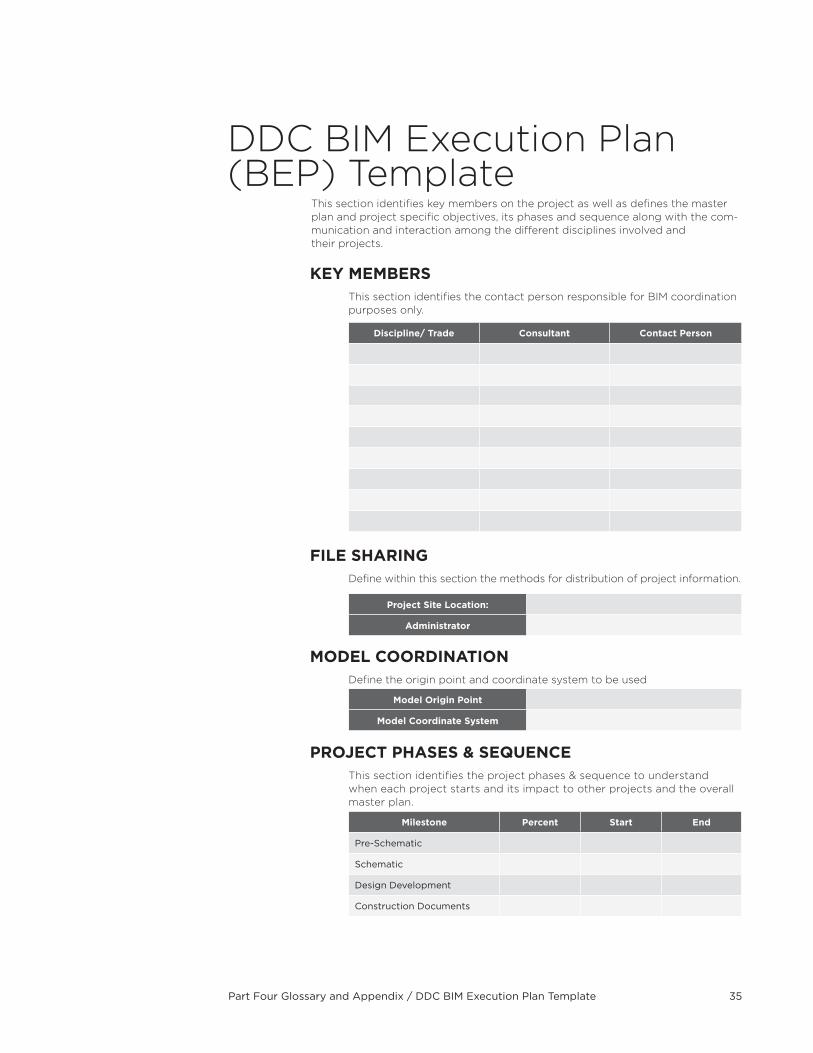
Part Four Glossary and Appendix / DDC BIM Execution Plan Template 35
DDC BIM Execution Plan (BEP) Template
This section identifies key members on the project as well as defines the master plan and project specific objectives, its phases and sequence along with the com-munication and interaction among the different disciplines involved and their projects .
KEY MEMBERsThis section identifies the contact person responsible for BIM coordination purposes only .
Discipline/ Trade Consultant Contact Person
FILE sHARInGDefine within this section the methods for distribution of project information .
Project site Location:
Administrator
MODEL COORDInATIOn Define the origin point and coordinate system to be used
Model Origin Point
Model Coordinate system
PROjECT PHAsEs & sEQUEnCEThis section identifies the project phases & sequence to understand when each project starts and its impact to other projects and the overall master plan .
Milestone Percent start End
Pre-Schematic
Schematic
Design Development
Construction Documents
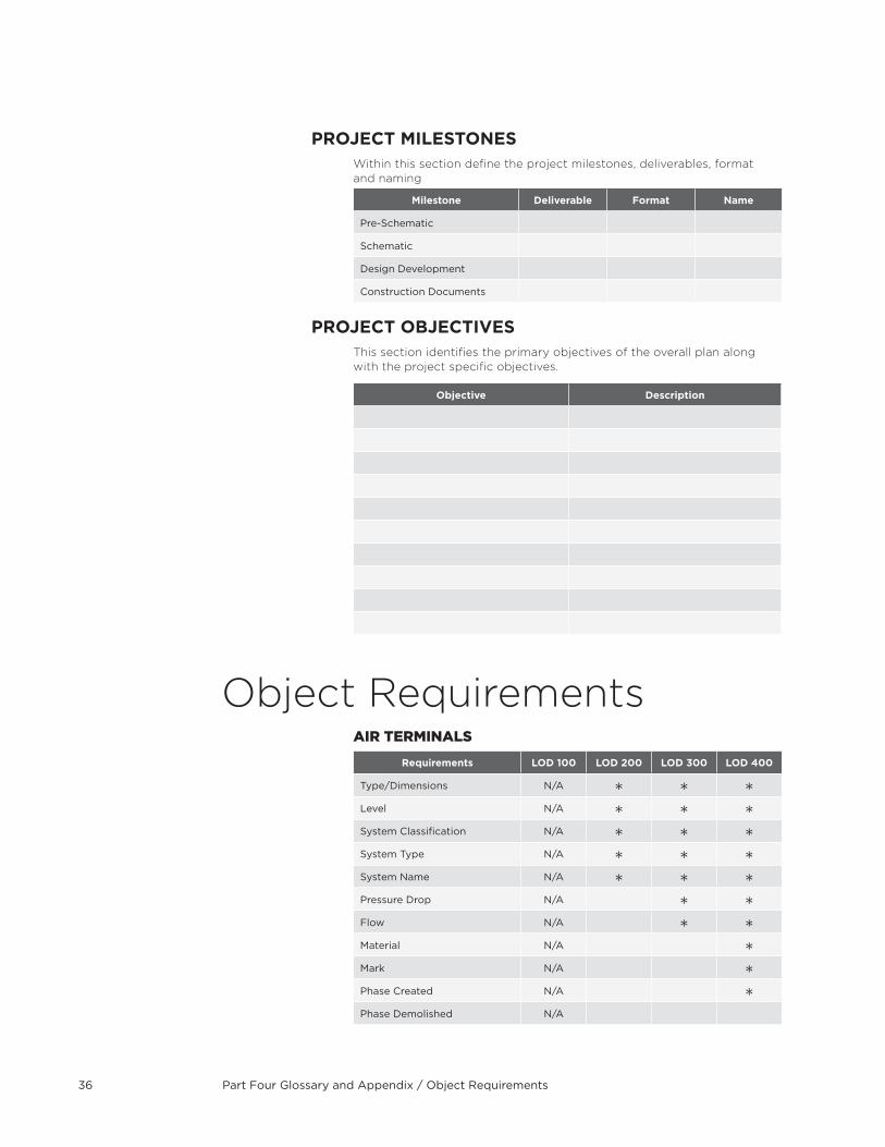
Part Four Glossary and Appendix / Object Requirements36
PROjECT MILEsTOnEsWithin this section define the project milestones, deliverables, format and naming
Milestone Deliverable Format name
Pre-Schematic
Schematic
Design Development
Construction Documents
PROjECT OBjECTIVEsThis section identifies the primary objectives of the overall plan along with the project specific objectives .
Objective Description
Object Requirementsair TerMinaLs
Requirements LOD 100 LOD 200 LOD 300 LOD 400
Type/Dimensions N/A
Level N/A
System Classification N/A
System Type N/A
System Name N/A
Pressure Drop N/A
Flow N/A
Material N/A
Mark N/A
Phase Created N/A
Phase Demolished N/A
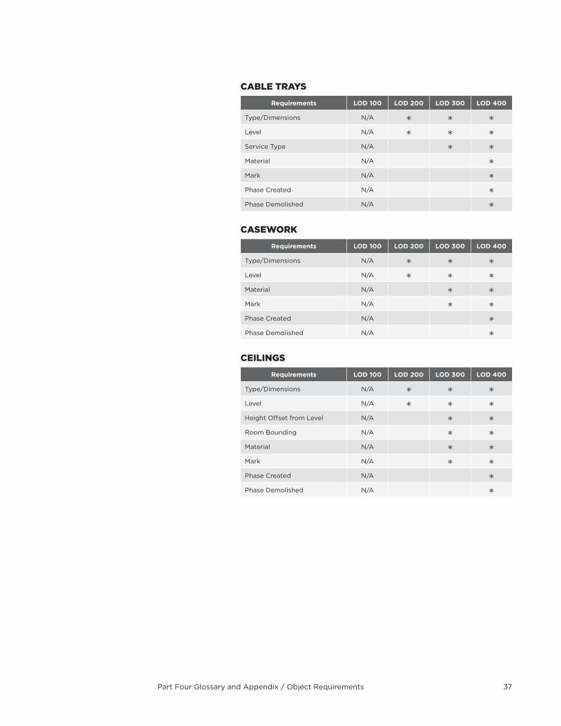
Part Four Glossary and Appendix / Object Requirements 37
caBLe TraYs
Requirements LOD 100 LOD 200 LOD 300 LOD 400
Type/Dimensions N/A
Level N/A
Service Type N/A
Material N/A
Mark N/A
Phase Created N/A
Phase Demolished N/A
caseWOrK
Requirements LOD 100 LOD 200 LOD 300 LOD 400
Type/Dimensions N/A
Level N/A
Material N/A
Mark N/A
Phase Created N/A
Phase Demolished N/A
ceiLings
Requirements LOD 100 LOD 200 LOD 300 LOD 400
Type/Dimensions N/A
Level N/A
Height Offset from Level N/A
Room Bounding N/A
Material N/A
Mark N/A
Phase Created N/A
Phase Demolished N/A
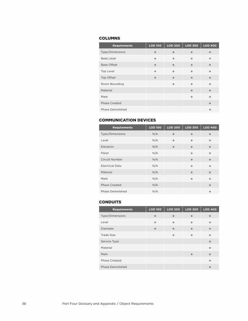
Part Four Glossary and Appendix / Object Requirements38
cOLUMns
Requirements LOD 100 LOD 200 LOD 300 LOD 400
Type/Dimensions
Base Level
Base Offset
Top Level
Top Offset
Room Bounding
Material
Mark
Phase Created
Phase Demolished
cOMMUnicaTiOn DeVices
Requirements LOD 100 LOD 200 LOD 300 LOD 400
Type/Dimensions N/A
Level N/A
Elevation N/A
Panel N/A
Circuit Number N/A
Electrical Data N/A
Material N/A
Mark N/A
Phase Created N/A
Phase Demolished N/A
cOnDUiTs
Requirements LOD 100 LOD 200 LOD 300 LOD 400
Type/Dimensions
Level
Diameter
Trade Size
Service Type
Material
Mark
Phase Created
Phase Demolished
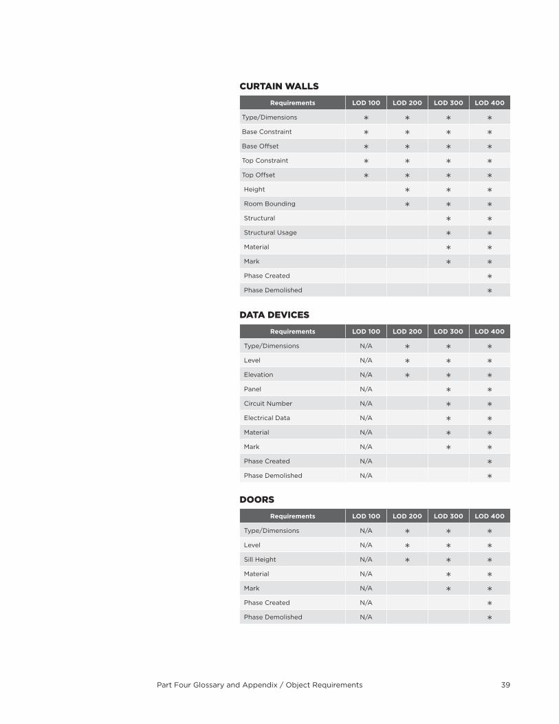
Part Four Glossary and Appendix / Object Requirements 39
cUrTain WaLLs
Requirements LOD 100 LOD 200 LOD 300 LOD 400
Type/Dimensions
Base Constraint
Base Offset
Top Constraint
Top Offset
Height
Room Bounding
Structural
Structural Usage
Material
Mark
Phase Created
Phase Demolished
DaTa DeVices
Requirements LOD 100 LOD 200 LOD 300 LOD 400
Type/Dimensions N/A
Level N/A
Elevation N/A
Panel N/A
Circuit Number N/A
Electrical Data N/A
Material N/A
Mark N/A
Phase Created N/A
Phase Demolished N/A
DOOrs
Requirements LOD 100 LOD 200 LOD 300 LOD 400
Type/Dimensions N/A
Level N/A
Sill Height N/A
Material N/A
Mark N/A
Phase Created N/A
Phase Demolished N/A

Part Four Glossary and Appendix / Object Requirements40
DUcTs
Requirements LOD 100 LOD 200 LOD 300 LOD 400
Type/Dimensions
Level
Offset
Start Offset
End Offset
System Classification
System Type
System Name
System Abbreviation
Material
Mark
Phase Created
Phase Demolished
eLecTricaL eQUiPMenT
Requirements LOD 100 LOD 200 LOD 300 LOD 400
Type/Dimensions
Level
Elevation
Panel Name
Mounting
Enclosure
Breakers
Mains
Circuit Naming
Circuit Prefix Separator
Circuit Prefix
Short Circuit Rating
Distribution System
Feed
Material
Mark
Phase Created
Phase Demolished
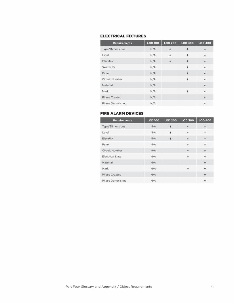
Part Four Glossary and Appendix / Object Requirements 41
eLecTricaL FiXTUres
Requirements LOD 100 LOD 200 LOD 300 LOD 400
Type/Dimensions N/A
Level N/A
Elevation N/A
Switch ID N/A
Panel N/A
Circuit Number N/A
Material N/A
Mark N/A
Phase Created N/A
Phase Demolished N/A
Fire aLarM DeVices
Requirements LOD 100 LOD 200 LOD 300 LOD 400
Type/Dimensions N/A
Level N/A
Elevation N/A
Panel N/A
Circuit Number N/A
Electrical Data N/A
Material N/A
Mark N/A
Phase Created N/A
Phase Demolished N/A
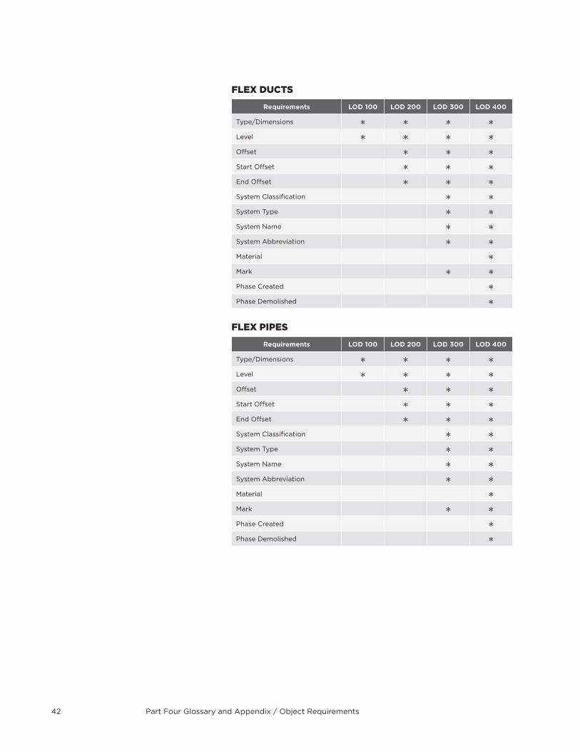
Part Four Glossary and Appendix / Object Requirements42
FLeX DUcTs
Requirements LOD 100 LOD 200 LOD 300 LOD 400
Type/Dimensions
Level
Offset
Start Offset
End Offset
System Classification
System Type
System Name
System Abbreviation
Material
Mark
Phase Created
Phase Demolished
FLeX PiPes
Requirements LOD 100 LOD 200 LOD 300 LOD 400
Type/Dimensions
Level
Offset
Start Offset
End Offset
System Classification
System Type
System Name
System Abbreviation
Material
Mark
Phase Created
Phase Demolished
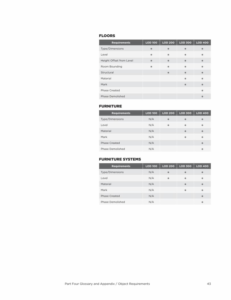
Part Four Glossary and Appendix / Object Requirements 43
FLOOrs
Requirements LOD 100 LOD 200 LOD 300 LOD 400
Type/Dimensions
Level
Height Offset from Level
Room Bounding
Structural
Material
Mark
Phase Created
Phase Demolished
FUrniTUre
Requirements LOD 100 LOD 200 LOD 300 LOD 400
Type/Dimensions N/A
Level N/A
Material N/A
Mark N/A
Phase Created N/A
Phase Demolished N/A
FUrniTUre sYsTeMs
Requirements LOD 100 LOD 200 LOD 300 LOD 400
Type/Dimensions N/A
Level N/A
Material N/A
Mark N/A
Phase Created N/A
Phase Demolished N/A
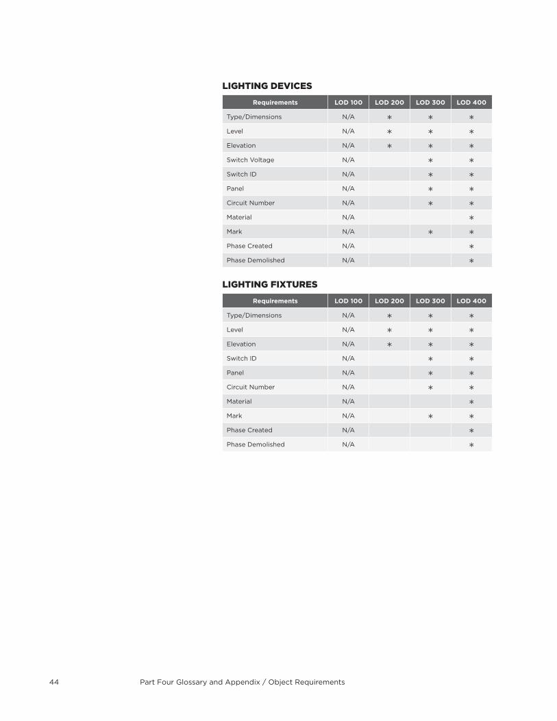
Part Four Glossary and Appendix / Object Requirements44
LigHTing DeVices
Requirements LOD 100 LOD 200 LOD 300 LOD 400
Type/Dimensions N/A
Level N/A
Elevation N/A
Switch Voltage N/A
Switch ID N/A
Panel N/A
Circuit Number N/A
Material N/A
Mark N/A
Phase Created N/A
Phase Demolished N/A
LigHTing FiXTUres
Requirements LOD 100 LOD 200 LOD 300 LOD 400
Type/Dimensions N/A
Level N/A
Elevation N/A
Switch ID N/A
Panel N/A
Circuit Number N/A
Material N/A
Mark N/A
Phase Created N/A
Phase Demolished N/A
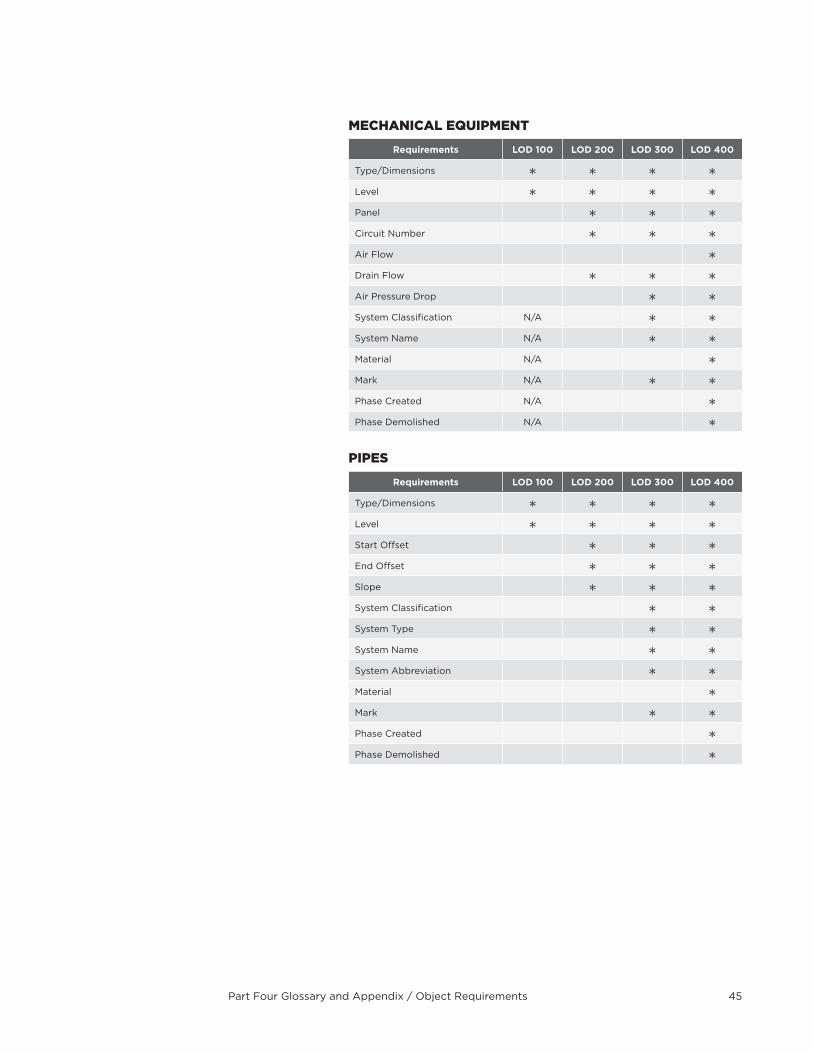
Part Four Glossary and Appendix / Object Requirements 45
MecHanicaL eQUiPMenT
Requirements LOD 100 LOD 200 LOD 300 LOD 400
Type/Dimensions
Level
Panel
Circuit Number
Air Flow
Drain Flow
Air Pressure Drop
System Classification N/A
System Name N/A
Material N/A
Mark N/A
Phase Created N/A
Phase Demolished N/A
PiPes
Requirements LOD 100 LOD 200 LOD 300 LOD 400
Type/Dimensions
Level
Start Offset
End Offset
Slope
System Classification
System Type
System Name
System Abbreviation
Material
Mark
Phase Created
Phase Demolished
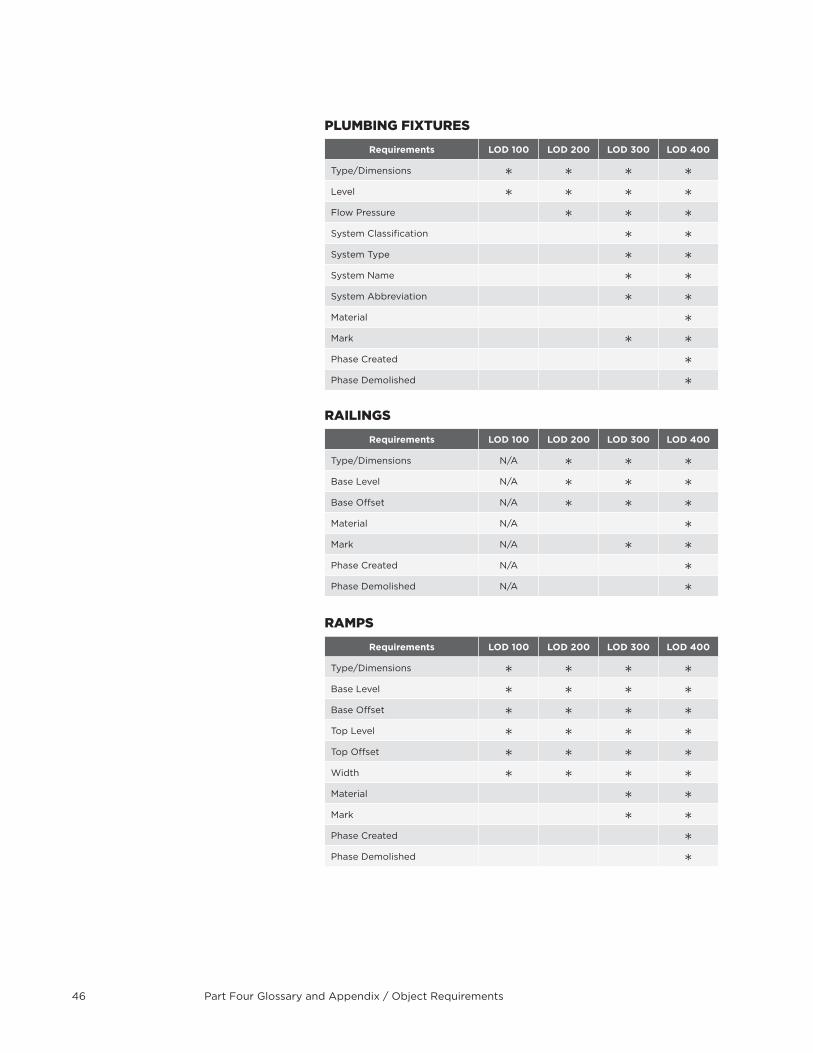
Part Four Glossary and Appendix / Object Requirements46
PLUMBing FiXTUres
Requirements LOD 100 LOD 200 LOD 300 LOD 400
Type/Dimensions
Level
Flow Pressure
System Classification
System Type
System Name
System Abbreviation
Material
Mark
Phase Created
Phase Demolished
raiLings
Requirements LOD 100 LOD 200 LOD 300 LOD 400
Type/Dimensions N/A
Base Level N/A
Base Offset N/A
Material N/A
Mark N/A
Phase Created N/A
Phase Demolished N/A
raMPs
Requirements LOD 100 LOD 200 LOD 300 LOD 400
Type/Dimensions
Base Level
Base Offset
Top Level
Top Offset
Width
Material
Mark
Phase Created
Phase Demolished
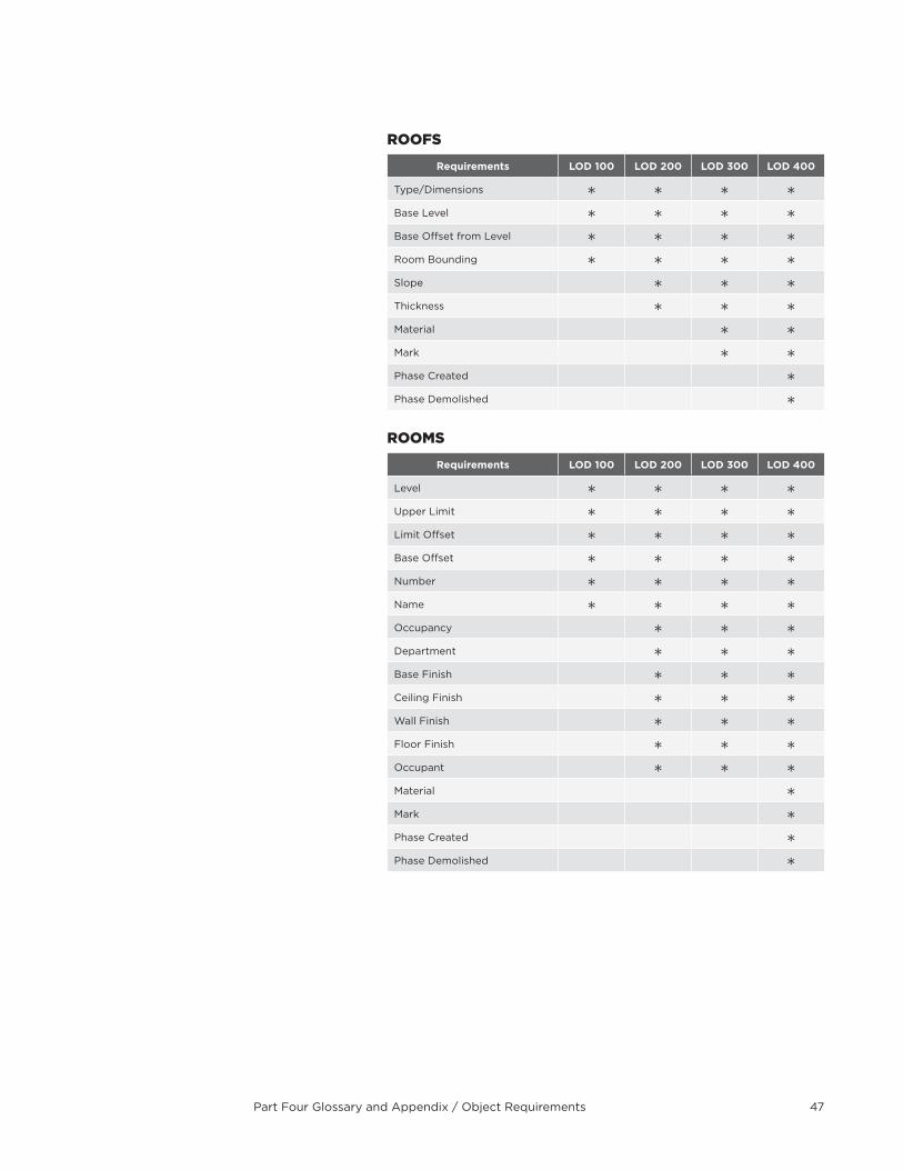
Part Four Glossary and Appendix / Object Requirements 47
rOOFs
Requirements LOD 100 LOD 200 LOD 300 LOD 400
Type/Dimensions
Base Level
Base Offset from Level
Room Bounding
Slope
Thickness
Material
Mark
Phase Created
Phase Demolished
rOOMs
Requirements LOD 100 LOD 200 LOD 300 LOD 400
Level
Upper Limit
Limit Offset
Base Offset
Number
Name
Occupancy
Department
Base Finish
Ceiling Finish
Wall Finish
Floor Finish
Occupant
Material
Mark
Phase Created
Phase Demolished
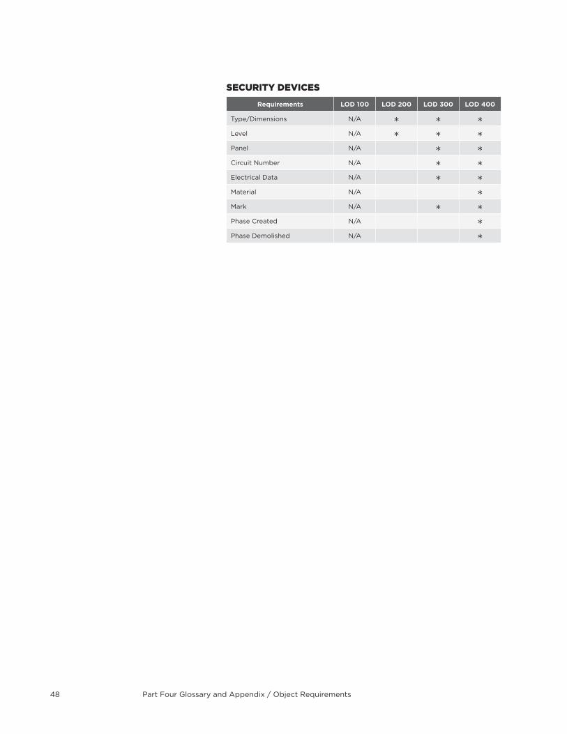
Part Four Glossary and Appendix / Object Requirements48
secUriTY DeVices
Requirements LOD 100 LOD 200 LOD 300 LOD 400
Type/Dimensions N/A
Level N/A
Panel N/A
Circuit Number N/A
Electrical Data N/A
Material N/A
Mark N/A
Phase Created N/A
Phase Demolished N/A
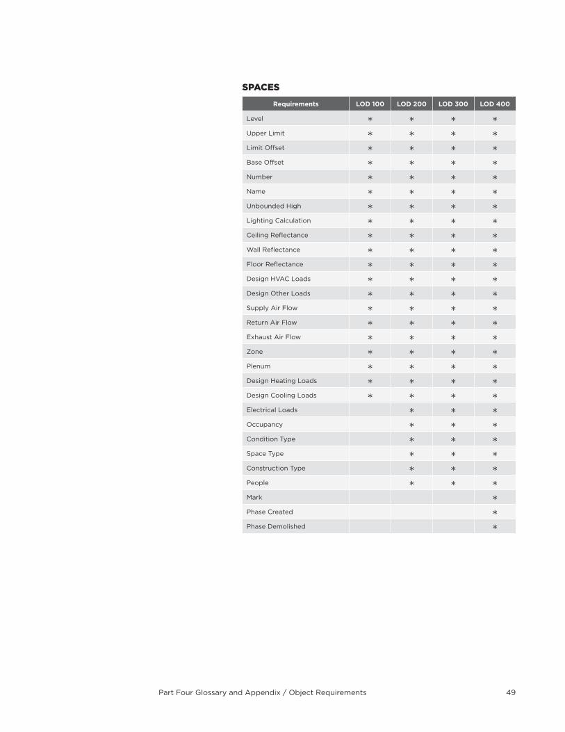
Part Four Glossary and Appendix / Object Requirements 49
sPaces
Requirements LOD 100 LOD 200 LOD 300 LOD 400
Level
Upper Limit
Limit Offset
Base Offset
Number
Name
Unbounded High
Lighting Calculation
Ceiling Reflectance
Wall Reflectance
Floor Reflectance
Design HVAC Loads
Design Other Loads
Supply Air Flow
Return Air Flow
Exhaust Air Flow
Zone
Plenum
Design Heating Loads
Design Cooling Loads
Electrical Loads
Occupancy
Condition Type
Space Type
Construction Type
People
Mark
Phase Created
Phase Demolished
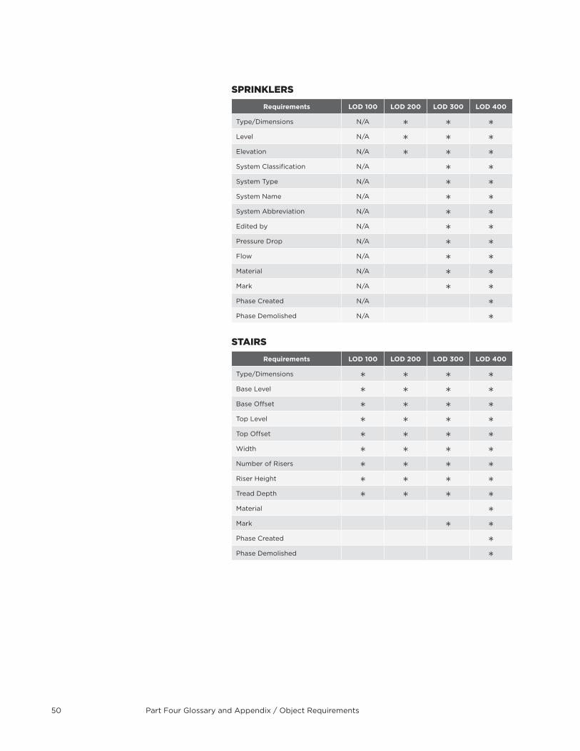
Part Four Glossary and Appendix / Object Requirements50
sPrinKLers
Requirements LOD 100 LOD 200 LOD 300 LOD 400
Type/Dimensions N/A
Level N/A
Elevation N/A
System Classification N/A
System Type N/A
System Name N/A
System Abbreviation N/A
Edited by N/A
Pressure Drop N/A
Flow N/A
Material N/A
Mark N/A
Phase Created N/A
Phase Demolished N/A
sTairs
Requirements LOD 100 LOD 200 LOD 300 LOD 400
Type/Dimensions
Base Level
Base Offset
Top Level
Top Offset
Width
Number of Risers
Riser Height
Tread Depth
Material
Mark
Phase Created
Phase Demolished
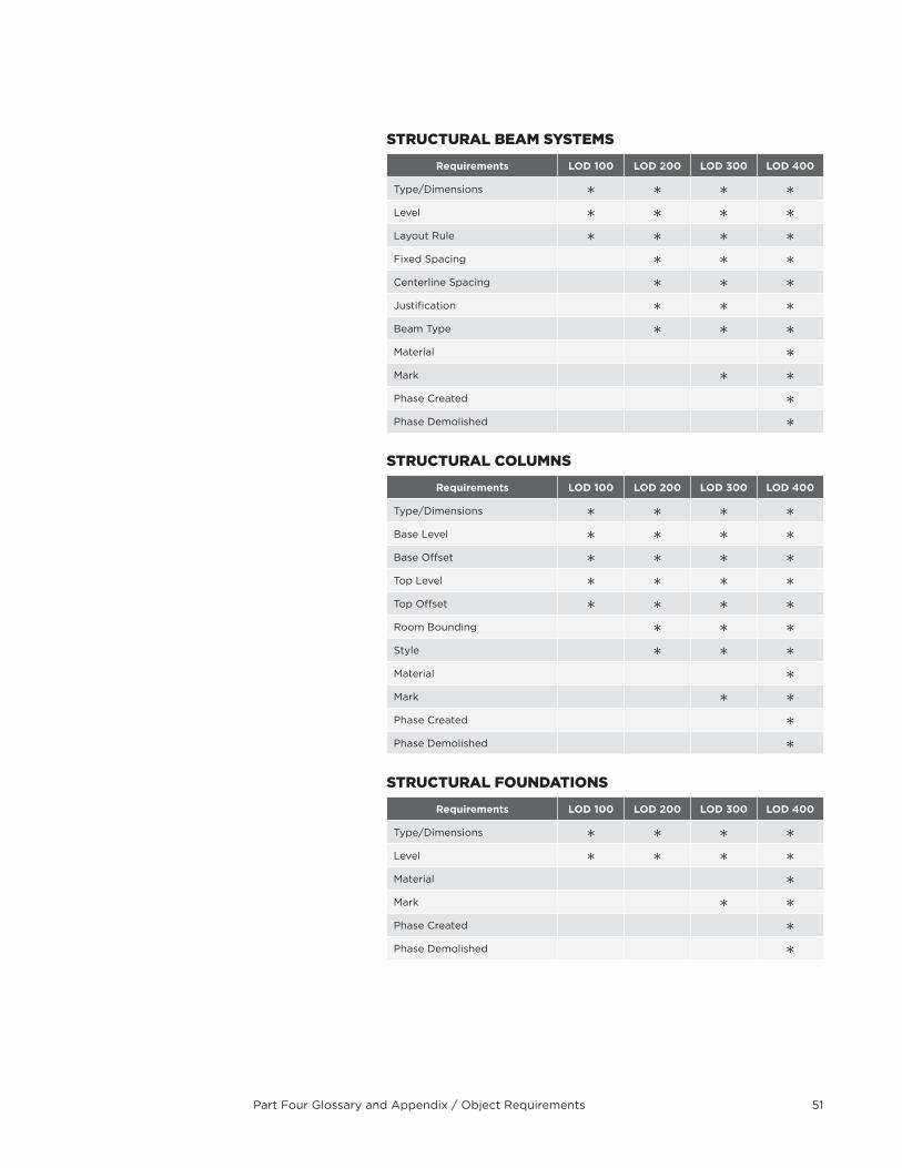
Part Four Glossary and Appendix / Object Requirements 51
sTrUcTUraL BeaM sYsTeMs
Requirements LOD 100 LOD 200 LOD 300 LOD 400
Type/Dimensions
Level
Layout Rule
Fixed Spacing
Centerline Spacing
Justification
Beam Type
Material
Mark
Phase Created
Phase Demolished
sTrUcTUraL cOLUMns
Requirements LOD 100 LOD 200 LOD 300 LOD 400
Type/Dimensions
Base Level
Base Offset
Top Level
Top Offset
Room Bounding
Style
Material
Mark
Phase Created
Phase Demolished
sTrUcTUraL FOUnDaTiOns
Requirements LOD 100 LOD 200 LOD 300 LOD 400
Type/Dimensions
Level
Material
Mark
Phase Created
Phase Demolished
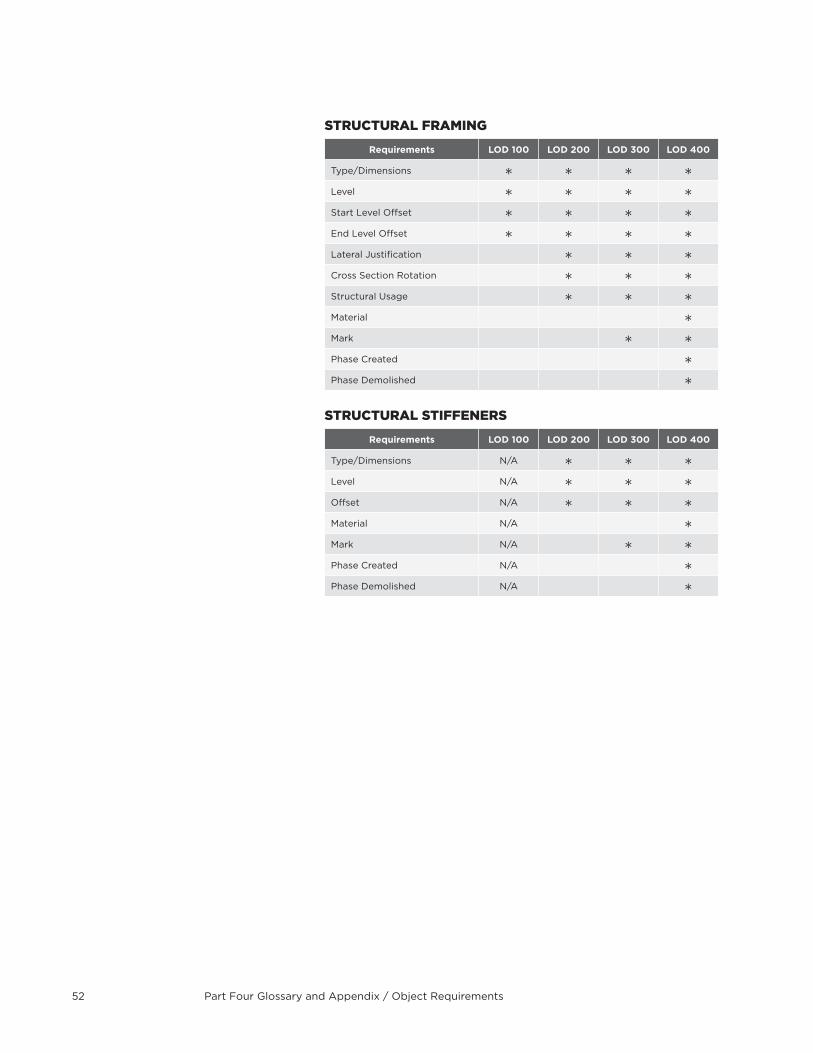
Part Four Glossary and Appendix / Object Requirements52
sTrUcTUraL FraMing
Requirements LOD 100 LOD 200 LOD 300 LOD 400
Type/Dimensions
Level
Start Level Offset
End Level Offset
Lateral Justification
Cross Section Rotation
Structural Usage
Material
Mark
Phase Created
Phase Demolished
sTrUcTUraL sTiFFeners
Requirements LOD 100 LOD 200 LOD 300 LOD 400
Type/Dimensions N/A
Level N/A
Offset N/A
Material N/A
Mark N/A
Phase Created N/A
Phase Demolished N/A
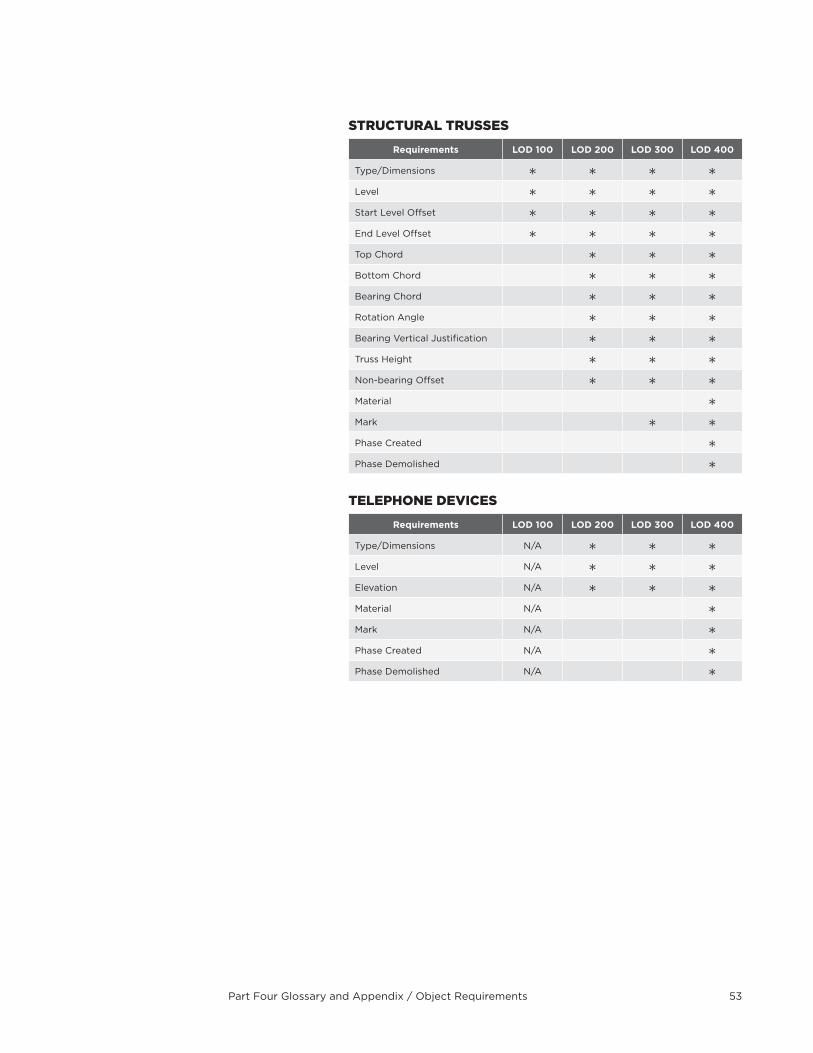
Part Four Glossary and Appendix / Object Requirements 53
sTrUcTUraL TrUsses
Requirements LOD 100 LOD 200 LOD 300 LOD 400
Type/Dimensions
Level
Start Level Offset
End Level Offset
Top Chord
Bottom Chord
Bearing Chord
Rotation Angle
Bearing Vertical Justification
Truss Height
Non-bearing Offset
Material
Mark
Phase Created
Phase Demolished
TeLePHOne DeVices
Requirements LOD 100 LOD 200 LOD 300 LOD 400
Type/Dimensions N/A
Level N/A
Elevation N/A
Material N/A
Mark N/A
Phase Created N/A
Phase Demolished N/A
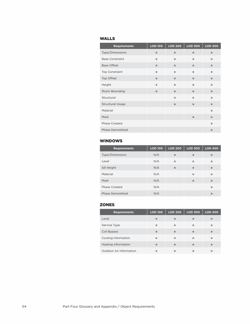
Part Four Glossary and Appendix / Object Requirements54
WaLLs
Requirements LOD 100 LOD 200 LOD 300 LOD 400
Type/Dimensions
Base Constraint
Base Offset
Top Constraint
Top Offset
Height
Room Bounding
Structural
Structural Usage
Material
Mark
Phase Created
Phase Demolished
WinDOWs
Requirements LOD 100 LOD 200 LOD 300 LOD 400
Type/Dimensions N/A
Level N/A
Sill Height N/A
Material N/A
Mark N/A
Phase Created N/A
Phase Demolished N/A
ZOnes
Requirements LOD 100 LOD 200 LOD 300 LOD 400
Level
Service Type
Coil Bypass
Cooling Information
Heating Information
Outdoor Air Information

Part Four Glossary and Appendix / Updates and Revisions 55
Updates and RevisionsThe dynamic nature of BIM technology dictates that this document will change over time . Changes to this document will be made as needed for the successful implementation of BIM on DDC projects as determined by the DDC BIM manager .
Changes may be made based on errors and omissions, as well as to enhance or update the guidelines based on changes in the BIM process . This document will evolve and continue to be reviewed . Revisions and updates to these guidelines may be submitted in writing to the DDC BIM manager .
Contact InformationQuestions regarding the DDC - BIM Guidelines provided within this Manual should be directed to:
Safiy Abdur-Rahman BIM Manager NYC Department of Design + Construction 30-30 Thomson Ave . Long Island City, NY 11101
Cover image: New York City Police Department, Queens Perkins + Will with Michael Fieldman Architects