Embed Size (px)
Citation preview

1
BIM SOFTWARE EVALUATION MODEL FOR GENERAL CONTRACTORS
By
JOSE MAURICIO RUIZ
A THESIS PRESENTED TO THE GRADUATE SCHOOL OF THE UNIVERSITY OF FLORIDA IN PARTIAL FULFILLMENT
OF THE REQUIREMENTS FOR THE DEGREE OF MASTER OF SCIENCE IN BUILDING CONSTRUCTION
UNIVERSITY OF FLORIDA
2009

2
©2009 Jose Mauricio Ruiz

3
To my family and friends, for all their support and guidance throughout this entire process

4
ACKNOWLEDGMENTS
I would like to thank Dr. R. Raymond Issa, who has been a great advisor and mentor
throughout my studies at the University of Florida. His knowledge as well as enthusiasm toward
my studies was extremely helpful in accomplishing my thesis. I would also like to thank Dr.
Svetlana Olbina for her direction during the preparation of my thesis, it was crucial to my
research objectives. I would also like to thank Dr. Ian Flood for his contributions to this study.
I thank my family and friends for their support and guidance throughout the entire time I was in
school. I would like to specifically thank my parents and brothers. Without their encouragement,
I would not have been able to complete my studies at the University of Florida.
5
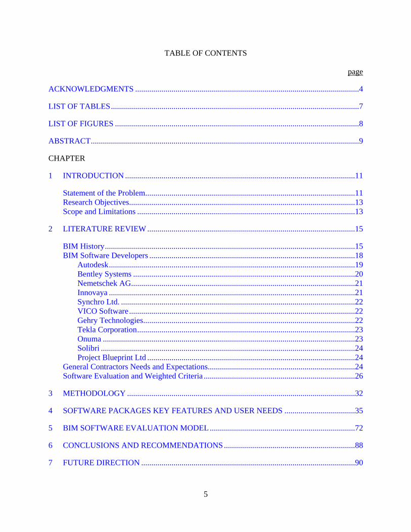
TABLE OF CONTENTS page
ACKNOWLEDGMENTS ...............................................................................................................4
LIST OF TABLES ...........................................................................................................................7
LIST OF FIGURES .........................................................................................................................8
ABSTRACT .....................................................................................................................................9
CHAPTER
1 INTRODUCTION ..................................................................................................................11
Statement of the Problem ........................................................................................................11 Research Objectives ................................................................................................................13 Scope and Limitations ............................................................................................................13
2 LITERATURE REVIEW .......................................................................................................15
BIM History ............................................................................................................................15 BIM Software Developers ......................................................................................................18
Autodesk ..........................................................................................................................19 Bentley Systems ..............................................................................................................20 Nemetschek AG ...............................................................................................................21 Innovaya ..........................................................................................................................21 Synchro Ltd. ....................................................................................................................22 VICO Software ................................................................................................................22 Gehry Technologies .........................................................................................................22 Tekla Corporation ............................................................................................................23 Onuma .............................................................................................................................23 Solibri ..............................................................................................................................24 Project Blueprint Ltd .......................................................................................................24
General Contractors Needs and Expectations .........................................................................24 Software Evaluation and Weighted Criteria ...........................................................................26
3 METHODOLOGY .................................................................................................................32
4 SOFTWARE PACKAGES KEY FEATURES AND USER NEEDS ...................................35
5 BIM SOFTWARE EVALUATION MODEL ........................................................................72
6 CONCLUSIONS AND RECOMMENDATIONS .................................................................88
7 FUTURE DIRECTION ..........................................................................................................90

6
APPENDIX: PROGRAMMING OF THE BIM SOFTWARE EVALUATION MODEL FOR GENERAL CONTRACTORS IN MS VISUAL BASIC ..............................................92
LIST OF REFERENCES .............................................................................................................111
BIOGRAPHICAL SKETCH .......................................................................................................115
7
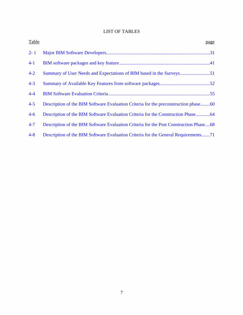
LIST OF TABLES
Table page 2- 1 Major BIM Software Developers.......................................................................................31
4-1 BIM software packages and key feature ............................................................................41
4-2 Summary of User Needs and Expectations of BIM based in the Surveys .........................51
4-3 Summary of Available Key Features from software packages ..........................................52
4-4 BIM Software Evaluation Criteria .....................................................................................55
4-5 Description of the BIM Software Evaluation Criteria for the preconstruction phase ........60
4-6 Description of the BIM Software Evaluation Criteria for the Construction Phase ............64
4-7 Description of the BIM Software Evaluation Criteria for the Post Construction Phase ....68
4-8 Description of the BIM Software Evaluation Criteria for the General Requirements .......71

8
LIST OF FIGURES
Figure page 2-1 B-Rep Approach ................................................................................................................30
2-2 CSG Approach (Source: OpenGL 1996) ..........................................................................30
3-1 Methodology Process ........................................................................................................34
4-1 Evaluation Results for the software packages for the preconstruction phase ....................38
4-2 Evaluation Result of the BIM Software Packages for the Construction Phase .................39
4-3 Evaluation Result of the BIM Software Packages for the Post Construction Phase .........40
5-1 BIMSEM-GC Screen capture: Importance selection of the different criteria. ..................76
5-2 BIMSEM-GC Screen capture: Before clicking the recommendation button ....................77
5-3 BIMSEM-GC Screen capture: Preconstruction top five recommendations ......................78
5-4 BIMSEM-GC Screen capture: Preconstruction subtotal scores ........................................79
5-5 BIMSEM-GC Screen capture: Construction top five recommendations ...........................80
5-6 BIMSEM-GC Screen capture: Post Construction top five recommendations ...................81
5-7 Combination performance of the different top recommended software ............................82
5-8 Company’s Real BIM model compared with perceived BIM model ................................83
5-9 Recommended and Company’s subtotal behavior for Preconstruction .............................84
5-10 Recommended and Company’s subtotal behavior for Construction .................................85
5-11 Recommended and Company’s subtotal behavior for Post Construction .........................86
5-12 Recommended and Company’s subtotal behavior for the General Criteria ......................87
9
Abstract of Thesis Presented to the Graduate School of the University of Florida in Partial Fulfillment of the
Requirements for the Degree of Master of Science in Building Construction
BIM SOFTWARE EVALUATION MODEL FOR GENERAL CONTRACTORS
By
Jose Mauricio Ruiz
May 2009
Chair: Dr. R. Raymond Issa Co-chair: Dr. Svetlana Olbina Major: Building Construction
Building Information Modeling (BIM) is the most recent trend in information technology
in the construction industry. With different case studies showing that the proper implementation
of BIM technology can add value to the project, reducing costs, schedule, and preventing errors;
more and more companies are starting to implement BIM software as a tool in their project
workflow. Although, some companies use an appropriate implementation process, other
companies tend to just respond to the market trend and implement the software package that is
more popular in the industry without looking at the real company needs or software features.
This study looked at the different BIM user expectations and available software features
to develop a BIM Software Evaluation Model for General Contractors (BIMSEM-GC) which
based on the company needs recommends the top five software packages that best fit those
needs. The BIMSEM-GC should not be used alone when starting to implement BIM in any
company, but it should be used as part of a structured implementation process, looking at all the
changes in the company that an implementation of this kind will require.
The BIMSEM-GC looked at 11 BIM software developing companies to determine a list
of 33 different software packages that can be used for the general contractor during the

10
preconstruction, construction and post construction phases of the project. To determine the user’s
needs and expectations regarding to BIM a study of the results from two major public surveys
was used. Finally the combination of the available software features and the users needs and
expectations were used to create the BIMSEM-GC questionnaire using a 5-point Likert scale. By
taking into consideration the standard deviation and coefficient of variation at a 95% confidence
level for the obtained results, the model is able to recommend the top 5 BIM software packages
that best fit the company’s needs.
In conclusion, the BIMSEM-GC also shows the degree of involvement that the company
has in three different construction phases: preconstruction, construction and post construction,
thus allowing the company to detect gaps from one phase to the other one when implementing
BIM.
11
CHAPTER 1 INTRODUCTION
Construction companies are starting to implement Building Information Modeling (BIM)
capabilities into their everyday tasks. In order to implement their BIM capabilities needs,
companies are also facing a market full of options by the software vendors, promoting software
packages that promised to fill all their needs and beyond. With this overwhelming market, most
companies are starting to implement software packages that they are familiar with, without
making a proper analysis to determine the best option for the company’s needs. Jack Micklovich,
director of software management consulting at Corporate Software, Norwood, Mass, mentioned
in an article for ENR that companies are losing money because of uncoordinated software
purchases and a lack of understanding of what they have and how they are using the programs
(ref).
The goal of this study is to create a model to be used for general contractors to determine
which BIM software package is the one that best fits their company’s needs. The creation of the
model allows companies to establish their real BIM needs, and serves as a negotiation tool when
acquiring the software.
Statement of the Problem
General contractors are changing the way they do businesses. BIM is the new
construction technology trend in United States, with an increase in the number of companies
trying to implement it. Nowadays, contractors are using technology more than ever and
especially BIM tools, based on the proven fact that a well implemented technology can increase
productivity, improve quality, safety, reduce delays and reduce cost. Moreover, some of these
companies may be contemplating making the decision to adopt a BIM software package based
12
on marketing campaigns by the software vendor instead of using a rational analysis of their
company’s needs.
Contractors are starting to realize the major advantages of using BIM and the importance
of creating an accurate building information model for use in a virtual construction process. The
ability to visualize the entire project and be able to use those parameters to produce value during
its construction makes the contractors to look closely at the BIM capabilities and the prompt
implementation of these tools into the company. Contractors expect to see the greatest increase
in BIM usage in 2009. Thirty eight percent will be heavy users, up from 23% in 2008. Twelve
percent expect light use of BIM, compared to 45% the previous year (McGraw Hill Construction
2008).
As the use of BIM becomes more prevalent, general contractors are being bombarded
with different software packages and new companies are emerging almost every year, with new
BIM solutions. The plethora of packages and lack of knowledge lead construction companies to
making their buying decisions based on marketing campaigns or popularity, instead of the
selection of the software that offers the best solution for the contractors needs. In some cases the
company may not even be aware of the other solutions that the market is offering, making the
contractor spend money on a software package that may not fill all the company’s needs or
overpaying for a software package that does more than the company is ever going to need.
In conclusion, it is important to note the fact that more contractors are starting to use BIM
tools in their every day tasks. This usage establishes the need for an optimal implementation to
take maximum advantage of BIM capabilities and to assure the buyers that the selected software
will produce all that it promises. This research aims to create a model to be used as part of that
13
implementation strategy, allowing the contractor to have a better understanding of their needs
when acquiring BIM software.
Research Objectives
The objective of this study is to analyze the needs of general contractors in the industry
when using BIM, and to create an evaluation model to determine the most useful software to
implement according to the company’s needs. In addition, two BIM evaluation tools were also
developed, one from the user point of view and the other based on the software features available
from the different software vendors.
Scope and Limitations
The study produced an evaluation model for different BIM software, looking at the different
needs of general contractors. The scope of those needs was determined by trying to answer the
following questions:
• What are the general requirements for a general contractor when buying any computer software?
• What are the necessary features for a general contractor during the preconstruction phase?
• What are the necessary features for a general contractor during the construction phase?
• What are the necessary features for a general contractor during the post construction phase?
• What is the optimal evaluation technique when determine the best software for a company?
This study took the most common needs and available features required by general
contractors and provided by software vendors, and put those needs into evaluation criteria to
allow any company to measure the best option when buying BIM software.
Finally, the evaluation model looked at the company’s needs and according to their
ranking in importance recommended five different software packages that fill those needs The

14
needs analyzed and taken into consideration covered the involvement of the company in the
different areas of preconstruction, construction, and post construction.
This study was conducted as an academic exercise to create a starting point for
companies looking to implement BIM software. The model did not determine the best software
in the market, but the software that best fits a specific company needs. The created model is not
fixed and it should be adapted to every company’s reality or variation.
The model is also only useful for a short period of time, due to the frequent
improvements and new capabilities that the software vendors offer. Therefore, the model should
be updated after a certain period of time. The evaluation model was developed considering that
general contractors will have to convert the design into a 3D model. Although more and more
design firms are designing using 3D design software, in the future there would be no conversion
from 2D to 3D and the contractor’s ability to start using the model is immediate and much less
expensive than with this consideration.
15
CHAPTER 2 LITERATURE REVIEW
This literature review is divided into four sections. Each section addresses one of the
following characteristics: BIM history, developers of the most used BIM software, the actual
needs and expectations of BIM users and the different techniques for the general software
evaluation and weighted criteria regarding BIM.
The first section starts with a brief definition of the BIM concept for the purposes of this
thesis and continues with a summary of the evolution of object-based parametric modeling along
the years to what is actually known as BIM. The second section develops a review of the most
used BIM software developers in the market, determining the level of BIM involvement of the
BIM developer. The third section of this literature review explores the different needs and
expectations of BIM users, separating these needs into the different project phases:
preconstruction, construction and post construction. This section also covers the importance and
most used applications specifically for contractors trying to identify what the minimum BIM
software features would be for a contractor trying to implement this technology in their everyday
workflow.
Finally, the last section of this literature review covers research about the different
weighted and evaluation models used to evaluate software packages and BIM, looking at the
Interactive BIM Maturity Model as a reference to create the BIM Software Evaluation Model for
General Contractors (BIMSEM-GC).
BIM History
Since the beginning of history, mankind has been interested in building construction;
from the Egyptians to the modern civilizations they all looked into ways to improve the
processes of construction. One of the methods that proved to be very efficient was to develop a
16
model of the new building to be constructed. In construction the master builder would create a
mockup of the building or what is called in other industries a prototype. Although, this process
was very popular for the manufacturing and other industries, it was not so feasible to develop
something like that in the construction industry. This is basically because the buildings are built
only once, therefore, there is no room to create a prototype. Sometimes the mockup was only a
visual representation, a 3D model of the building in real life with the objective to sell the idea of
the building and never to be used as part of the construction management workflow.
Looking at the advances of other industries using digital tools the construction industry
started to look for ways to develop their own solutions and answers to the question of how to
create a prototype of a building that needs to be build only one time? A response that seems to be
very obvious nowadays is to create a virtual project, but this answer involves more than just the
ability to draw the project in 2D or 3D, it also involves looking for ways to assign properties to
every line and every part of the project. Properties and elements that represent the reality of that
particular project, allow all the parties involved in the project to feed the model and finally have
an accurate virtual project. This desire has evolved into what is now know as part of the Building
Information Model (BIM) technology, where the designers are no longer just making drawings,
but making models of the building, models with assigned properties that can be use to virtually
build the project.
The introduction of the BIM capabilities into the construction industry has opened a
window for designers, contractors, and owners to start looking at those desires again. Nowadays
it is possible to simulate the construction of the building at a certain level of detail, reducing risk
and creating better perspectives for the management of the construction.
17
BIM has its beginnings in research conducted decades ago in the field of computer aided
design. Moreover, there is no widely accepted definition for the term. For the purposes of this
thesis BIM was defined as the development and use of a computer software model to simulate
the construction and operation of a facility. The resulting model, a Building Information Model,
is a data rich object oriented, intelligent and parametric digital representation of the facility, from
which views and data appropriate to various users’ needs can be extracted and analyzed to
generate information that can be used to make decisions and improve the progress of delivering
the facility (AGC, The Contractors Guide to BIM 2007).
BIM or object based parametric modeling (previous name) was originally developed in
the 1980s. During the previous years, in 1973, efforts made by three groups, Ian Braid at
Cambridge University, Bruce Baumgart at Stanford, and Ari Requicha and Herb Voelcker at the
University of Rochester (Eastman 1999); produced two forms of solid modeling, the boundary
representation approach (B-rep) and the constructive Solid Geometry (CSG) that latter on
merged into one approach (See Figures 2-1 and 2-2). This first generation of tools supported 3D
facetted and cylindrical object modeling with associated attributes, which allowed objects to
compose into engineering assemblies, such as engines, process plants, or buildings (Eastman
1975, Requicha 1980). This merged approach to modeling was an important precursor to modern
parametric modeling (Eastman et al. 2008).
Building modeling based on 3D solid modeling was first developed in the late 1970s and
early 1980s. CAD systems, such as RUCAPS, TriCad, Calma, GDS (Day 2002), and University
research based systems at Carnegie-Mellon University and University of Michigan developed
their basic capabilities (Eastman et al. 2008). These solid modeling CAD systems were
functionally powerful but often overwhelmed the available computing power. This is why the
18
construction industry decided to adopt architectural drawing software packages, such as
AutoCAD, and Microstation that augmented the then current methods of working and supported
the digital generation of conventional 2D construction documents (Eastman et al. 2008).
Object Based Parametric Modeling: The current generation of BIM architectural design
tools grew out of the object based parametric modeling capabilities developed for mechanical
systems design. These concepts emerged as an extension of CSG and B-rep technologies, a
mixture of university research and intense industrial development, particularly by Parametric
Technologies Corporation (PTC) in the 1980s. The basic idea is that shape instances and other
properties can be defined and controlled according to a hierarchy of parameters at the assembly
and subassembly levels, as well as an individual object level. Some of the parameters depend on
user defined values. Others depend on fixed values, and still others are taken from or relative to
other shapes. The shapes can be 2D or 3D (Eastman et al. 2008).
The difference in parametric design is that the designer defines a model family or element
class, which is a set of relations and rules to control the parameters by which elements instances
can be generated and each vary according to their context, while the typical design approach is to
design an instance of a building element like a wall or door. The parameters used can be
distances, angles, and a different set of rules like parallel to, or distance from. These relations
allow the creation of rich data models than can be used later on the next phases of design,
construction and/or operation of the project.
BIM Software Developers
Several CAD systems available today, do not offer BIM capabilities, using the old B-rep
and CSG drawing standards instead of the object based parametric modeling. Nowadays more
companies are emerging with new solutions incorporating BIM tools as part of their software,

19
and also opening the market for a new type of consultant company, providing BIM solutions as a
third party developer with add on applications for the tool.
Four sources of information were looked at as part of this section for the literature
review, trying to identify the major software developers for the construction industry: BIM Wiki
(BIM Wiki 2009), BIM Handbook (Eastman et al. 2008), AGC BIM Guide (AGC of America
2007), and a survey by AECbytes (Khemlani 2007). Eleven software developers were identified
as shown in Table 2-1.
While some of the potential value of a contractor’s knowledge contribution is lost if the
contractor is not consulted until after the design phase is completed, significant benefits to the
contractor and the project team can still be realized by using a building model to support a
variety of construction work processes (Eastman et al. 2008). There are many software packages
in the market that address one or various necessities for a contractor to fill by using BIM. The
following list mentioned the most popular software developers and their main focus in the
construction industry.
Autodesk
Autodesk is an American multinational corporation that focuses on 2D and 3D design
software for use in architecture, engineering and building construction, manufacturing, and
media and entertainment. It was founded in 1982 and it became popular due to its software
AutoCAD that was and is still wildly used in the construction industry.
Nowadays, Autodesk has developed a broad portfolio of digital solutions to help users
visualize, simulate and analyze real world performance. The most known software packages
from Autodesk using BIM in the building construction sector are:
20
• Autodesk 3ds Max Design • Autodesk Design Review • Autodesk Navisworks • Revit Architecture • Revit Structure • Revit MEP
These software packages offer different types of features that go from drafting and
modeling capabilities of blending different types of models and to developing clash detection
analysis allowing for a better understanding of the building before it is built.
Bentley Systems
Bentley Systems is another important software developer in the market, providing
solutions for the building, plant, civil and geospatial vertical markets in the area of architecture,
engineering, construction (AEC) and operations. The company was founded in 1984 and its most
popular software solution for the building construction is Microstation which is an important
competitor for AutoCAD. Nowadays the company’s solutions are evolving through BIM and the
company just released a new line of packages that are object based parametric. The most used
software packages for the building construction include:
• Bentley Architecture V8i • Bentley Structural V8i • Bentley Building Electrical Systems V8i • Bentley Building Mechanical System V8i • ProjectWise Navigator (Incorporated Project 4D from CommonPoint) • ConstructSim (Previously part of CommonPoint)
The company is still offering their Microstation software, but is trying to moving forward
with the market trends implementing BIM tools into their solutions. The previously listed
software packages offer tools from drawing and modeling capacity to design rules reviews and
bidirectional capabilities with power and lighting analysis software. The new addition to the
21
Bentley team of Common Point allows them to offer 5D solutions as part of their portfolio and
they are making changes into ConstructSim to upgrade its capabilities.
Nemetschek AG
Nemetschek AG has been developing CAD software for the architecture, engineering,
and construction; entertainment; landscape design; and manufacturing fields since 1985 and in
the past years the company started to implement BIM technology into their software. The
Vectorworks product line is one of their top solutions. Although it is a great drawing and
modeling tool, it is not the top company’s BIM solution.
Graphisoft was recently bought by Nemetschek and became the company’s best BIM
solution. Graphisoft is based in Hungary and they claim that they were the first software in the
market that implemented BIM technologies. Nowadays the company only offers one main
software: Archicad 12, offering upgrades for different solutions like MEP Archicad allowing
making clash detection analysis within the models.
Innovaya
Innovaya is one of the new companies that emerged during the BIM boom. The company
focuses its solutions on the BIM environment and specifically to the building construction. It
also looks at interoperability issues between the Autodesk solutions and other construction
management software like Timberline, Primavera or MS Project. The list of software solutions
that Innovaya offers are:
• Innovaya Visual BIM • Innovaya Visual Quantity Take off • Innovaya Visual Estimating • Innovaya Design Estimating • Innovaya Visual Simulation
22
Synchro Ltd.
Synchro is another company that has emerged during this BIM revolution in the latest
years. Synchro focus its solutions to the project management area and specifically to project
schedule, linking the geometry of the project to more than 15 scheduling software allowing the
simulation of the project as well as resource management. Their basic software is called Synchro
Project Construction and the company also offers add on applications with their Synchro
professional, Synchro Express, Synchro Server, and Synchro Workgroup.
VICO Software
VICO Software is another new company in the CAD Design world, but in this case VICO
was formed through the acquisition of assests from Graphisoft company. They are basically the
previous solutions from Graphisoft that now work as an independent company. The company
offers a very complete set of programs that linked the design of the project with the construction
phase offering programs that allow to create the model from scratch and simulate construction
process inputting cost, creating earn value analysis and “what if” scenarios. Their line of
solutions included:
• Vico Constructor • Vico Estimator • Vico Control • Vico 5D Presenter • Vico Cost Explorer • Vico Change Manager
Gehry Technologies
Gehry Technologies (GT) provides technology and services to owners, developers,
architects, engineers, general contractors, fabricators, and other building industry
professionals. It was founded in 2002 and since then it has provided BIM solutions. Its main
software is the Digital Project Software that as its basic level allows to design and view 2D

23
and 3D models, but it counts with a number of add on creating Primavera Integration, MEP
Systems Routing, Photo Studio, etc.
Tekla Corporation
Tekla Corporation was established in 1966 in Espoo, Findland. It started as a structural
design software company but it adapts its solutions to the BIM environment. Nowadays Tekla
offers a division of Building and Construction where it looks at the model based design of steel
and concrete structures as well as the management of fabrication and construction. Tekla
building and construction mainly serves these customer segments:
• Tekla Structures, Full Detailing • Tekla Structures, Construction Management • Tekla Structures, Steel detailing • Tekla Structures, Precast Concrete Detailing • Tekla Structures, Reinforced Concrete Detailing • Tekla Structures, Engineering
Onuma
Onuma has been servicing the Architectural community since 1972 and it started offering
services through the world wide web in 1995. Nowadays it offers the Onuma Planning System
(OPS), an internet server model, where the various users are able to interact during the creation
and construction of the model. A unique characteristic of the Onuma solution is that it allows
different users to keep using their favorite software and put the models together in the OPS
application. The OPS by itself is more a design tool than a construction used tool, but the
capacity to bring models and update these models in real time allows the user to implement the
OPS during the entire process of the project, including operations and maintenance.

24
Solibri
Solibri was founded in 1999 to develop and market solutions that improve the quality of
BIM and making the design process more effective. With this in mind they offer the following
software packages:
• Solibri Model Chacker • Solibri Issue Locator • Solibri Model Viewer • Solibri IFC Optimizer
With the goal of optimizing BIM processes the different Solibri solutions allow the user
to analyze the models for integrity, quality and physical security. It also allows the checking for
clash detections and code verification, with a function locating the error on the original model.
Solibri also allows the user to see models from any IFC standard and to combine them as one
model using an IFC optimizer eliminating any redundant information.
Project Blueprint Ltd.
Project Blueprint is a company based in Australia that provides construction consultancy
and software development services. Their most popular software package is called Zero Defects
and it represents an Internet accessible database and tracking tool for reviewing a project.
General Contractors Needs and Expectations
Contractors are starting to recognize the benefits of BIM technology in their projects.
BIM allows for a smoother and better planned construction process that saves time and money
and reduces the potential for errors and conflicts (Eastman et al. 2008). More important, to obtain
the most possible benefits from the used of this technology, contractors must seek for an early
involvement in the project and push their subcontractors and all the parties involved in the
project to maximize the use of the tool.

25
An early involvement from the contractor into the project will allow for a smoother
transition of the information and reduce the wasted information value from one phase to the
other. While some of the potential value of a contractor’s knowledge is lost after the design
phase is complete, significant benefits to the contractor and the project team can still be realized
by using a building model to support a variety of construction work processes (Eastman et al.
2008).
Another consideration when applying BIM technology in the construction process is to
determine the level of detail of the information in model in order to determine the different
usages for the model. A contractor looking to utilize the model for scheduling will not need a
very detail model comparing to the one that a contractor will require to develop the estimate for
the same project.
Looking into the direct benefits of BIM technology for contractors there is a list of
applications that apply to most of them. Contractors are using different BIM applications as part
as their workflow: clash detection, quantity take off and cost estimating, construction analysis
and management, integration with cost and schedule control and other management functions,
offsite fabrication, and verification guidance, and tracking of construction activities (Eastman et
al. 2008). Gilligan and Kunz (2007) identified in their survey typical uses of BIM and Virtual
Design and Construction (VDC): 3D Clash detection, present architectural design, space
utilization, 4D clash detection, engage neighbors, present 4D schedule, cost estimation, enhance
submittals process, structural analysis, safety analysis, enhance shop drawing process, energy
analysis, drive shop fabrication equipment and others. AECbytes in a special report (2007)
showed that the most important criteria when looking at BIM software were: 1) Full support for
producing construction documents so that no other applications will be needed;. 2) Smart

26
objects, which maintain associativity, connectivity, and relationships with other objects; 3)
Availability of object libraries; 4) Ability to support distributed work processes, with multiple
team members working on the same project; and 5) Quality of help and supporting
documentation, tutorials and other learning results.
Overall, there is a general set of expectations and needs from BIM users in the
construction industry, and software developers are looking at those expectations to come up with
new solutions with add on capabilities to their software packages or completely new versions of
the software.
Software Evaluation and Weighted Criteria
By definition, to evaluate is to assign value to something, or to judge something. We can
improve this definition by considering why we evaluate; essentially we evaluate in order to
decide, that is to choose between different possibilities (Carney and Wallnau 1998).
Evaluating and selecting software packages that meet the company’s needs is not an easy
process. A number of different criteria should be considered to make sure that all the company’s
needs are being fulfilled at the time to recommend the software. Little research has been done
about evaluation methodology when selecting BIM software. The National Building Information
Modeling Standard (NBIS) committee published in 2007 the Interactive Capability Maturity
Model (I-CMM), but this was with the intent to provide a baseline for the minimum standard
criteria for a design to be considered a true BIM. Some software companies also offer evaluation
check lists that instead of being an evaluation of the market features are more like a bullet point
description of their software biasing the final result to selecting their software. Additionally,
magazines showed evaluation articles of specific software packages where the evaluations
sometimes were the authors’ criteria instead of representing a comparison of a set of general
criteria with the needs of a specific company.

27
Due to very little information being available about software evaluation models,
evaluation methodologies for general software, and evaluation criteria to buy educational
software packages were used as a baseline to generate the BIM Software Evaluation Model for
General Contractors (BIMSEM-GC). Northwest Educational Technology (NETC) published in
an article called Seven Steps for Responsible Software Selection (1995). In this article NETC
mentioned that a software selection should be the result of a process where an analysis of the
needs and goals of the final user should be considered as well as specific requirements. The next
steps should be to identify promising software, find reviews, try previews about the software and
then make the recommendations.
The previous methodology applied to the objectives of this study except for the part that
the BIMSEM-GC assumed that the user has no knowledge about any software in the market and
only knows what the company needs are. The methodology is not intended as rigid structure that
must be followed without any deviation, it is intended as guideline and an aid that can be adapted
according to the requirements of the individual organization (Patel and Hlupic 2002). This is
why the BIMSEM-GC should be able to interact with the individual organization, allowing the
organization to define the interest in certain areas of the BIM technologies.
Carney and Wallnau (1998) state in their research to create a basis for evaluation of
commercial software that seem to be three steeps that precede the actual selection and that make
it possible: 1) Identifiable alternative courses of action are identified. 2) Criteria are defined for
assigning a measure of merit and 3) Measure of merit is assigned to selected alternatives. This
approach seemed to fit more the requirements of a possible BIM software evaluation model,
where the first step would be to identify the possible software packages in the market, then
28
define the evaluation criteria and finally assign merit to those criteria, recommending the
software packages that fit company’s criteria the most.
Jadhav and Sonar (2009) proposed in their study a generic stage based methodology for
selection of any software package which consist of following seven stages:
• Determine the need for purchasing the system and preliminary investigation of the availability of packaged software that might be a suitable candidate, including high level investigation of software features and capabilities provided by vendor.
• Short listing of candidate packages
• Eliminating most candidate package that do not have required feature or do not work with the existing hardware, operating system and database management software or network.
• Using an evaluation technique to evaluate remaining packages and obtain a score or overall ranking of them.
• Doing further scrutiny by obtaining trial copy of top software packages and conducting an empirical evaluation. Pilot testing the tool in an appropriate environment.
• Negotiating a contract specifying software price, number of licenses, payment schedule, functional specification, repair and maintenance responsibilities, time table for delivery, and options to terminate any agreement.
• Purchasing and implementing most appropriate software package.
Although the Jadhav and Sonar (2009) methodology covered more steps than the intended
for this research it is also a great baseline to consider when creating the BIMSEM-GC. For the
three steps this study assumed that the general contractor does not count with the time or does
not have the knowledge to define which may be the list of software candidates, therefore the
model should be able to perform this tasks for them. For the fourth step of the Jadhav and Sonar
(2009) methodology, the model should be able to compare the company’s needs with the
software features, ranking them accordingly. The next fifth, sixth and seventh steps are not part
of this research, but are valuable recommendations for any BIM implementation process by a
general contractor.

29
With a possible methodology from the literature, the next step was to look at the best way to
evaluate the software packages. For this purpose the I-CMM weighted criteria was taken as a
baseline, where the different BIM levels were considered and are weighted by the designer
according to the characteristic of the project, giving a final score that is compared with the
minimum BIM score. Similarly weighted criteria was used for the BIMSEM-GC where the
general contractor will rank the importance of certain criteria to finally compare the score with
the different software packages score and recommend the top solutions.

30
Figure 2-1. B-Rep Approach
Figure 2-2. CSG Approach (Source: OpenGL 1996)

31
Table 2- 1. Major BIM Software Developers Major BIM software developers
BIM handbook AGC BIM guide Autodesk Autodesk Bentley Systems Bentley Systems
Graphisoft (Bought by Nemetschek AG) Graphisoft (Bought by Nemetschek AG)
Common Point Inc (Bought by Bentley Systems) Nemetschek VectorWorks Innovaya Synchro ltd. VICO Software
AECbytes survey BIM wiki Autodesk Autodesk Bentley Systems Bentley Systems
Graphisoft (Bought by Nemetschek AG) Graphisoft (Bought by Nemetschek AG)
Gehry Technologies Nemetschek SCIA Tekla Corporation Onuma Nemetschek Solibri Tekla Corporation Project Blueprint ltd VICO Software Gehry Technologies
32
CHAPTER 3 METHODOLOGY
This study looked at the creation of an evaluation model to be used by general contractors
as part of their implementation BIM process. To create the evaluation model 11 different
software developers and 33 software packages were used to recognize all the market offerings
and the results from two public surveys were used to recognize the user needs and expectations
from BIM.
The results from the analysis of the offer and demand regarding to BIM were summarized for
the different phases of the project were the general contractor may be involved: preconstruction,
construction and post construction. From this summary a questionnaire was created to be
answered by the general contractor using the model as part of the evaluation model, trying to
identify the company’s needs and involvement at the time of implementing certain software.
Followed is a detail explanation of the followed methodology to come up with the BIM
Evaluation Model (See Figure 3-1).
• The first phase was to conduct a literature review about the history and evolution of BIM, starting by setting the BIM concept to be used during the elaboration of this thesis. The AGC definition was the most appropriate, filling the essence of the concept and trying to explain what BIM is? from the contractors’ point of view. The analysis of the history of BIM covered its beginnings as a parametric object oriented technology and some of the obstacles that the people pushing this technology suffer from during its development. The next step of the literature review was to identify the major BIM software developers in the US market, were four different sources of information were looked at, including books, surveys, web pages, and associations reports regarding to BIM. From these four sources of information 11 software developers were identified and a detailed description of the company was developed during the literature review. Next in the literature review, two major public surveys results were analyze to identify the general contractor’s needs and expectations regarding to BIM. Finally as part of the literature review, a research about the different methods to evaluate different software packages was done by looking at journal papers and published books about the topic.
• The second phase was to create both check lists: one for the available features from the different BIM software packages in the market that can be used by the general contractor and the other check list where the user needs were identified. To develop the first list, 33

33
software packages were analyze from the 11 companies identified in the literature review phase.
• During the selection of the programs to be analyzed the main criteria was to look at software packages that could be used by the general contractor during the preconstruction, construction and post construction phase. On the other hand, to create the user expectations check list, the two surveys analyzed during the literature review phase were summarized to identify the main expectations and needs when using BIM.
• The next phase after the creation of both check lists was to create the evaluation model. The evaluation criteria were developed taking into consideration items from both check lists and looking at the contractor needs during the preconstruction, construction, post construction and general consideration when buying any software package. A 5-point Likert scale was selected to rank the importance of the different questions that the model asked to the contractor giving a final score for every area of the project. After the questionnaire and the Likert scale were applied, the next step of this phase was to rank the 33 software packages with the questioner and the developed knowledge. This ranking was used after the programming step to compare and recommend the top five software packages that fit the best the company’s needs. For the comparison and recommendation of the top five software a measure of dispersion and variation between the answers from the company and the different company’s needs was used. The answers were compared by calculating the standard deviation and the coefficient of variation at 95% confidence for all the 33 software packages and the company’s needs. Visual Basic due its the automated link with Microsoft Excel was used to write the program that generates the calculations automatically once the user of the model has input all their evaluation criteria.
• The last phase was to analyze the different possible results from the model at the time of its implementation giving future directions, recommendations and conclusions.

34
Figure 3-1. Methodology Process
35
CHAPTER 4 SOFTWARE PACKAGES KEY FEATURES AND USER NEEDS
Evaluating any kind of software is a complex process, as discussed in the literature
review there is no formal evaluation model for BIM related software. Although, there is a list of
major BIM software developers in the United States and a couple surveys trying to identify the
needs and expectations from BIM users. Also from the literature review, a basic methodology
that can be applied to the evaluate software in general was discovered. Using the concepts and
methodologies discovered during the literature review the BIM Software Evaluation Model for
General Contractors (BIMSEM-GC) was created.
This chapter covers the results from the analysis of the different software packages and
the user needs and expectations regarding BIM. The final result of the analysis was the creation
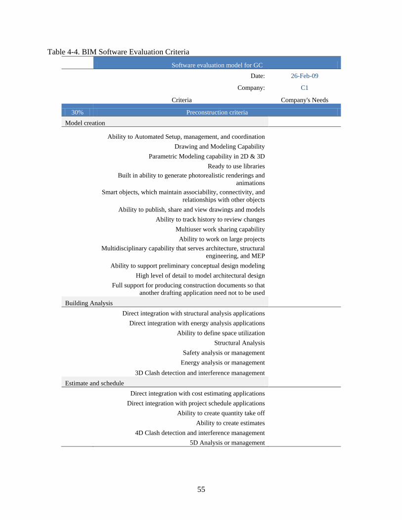
of a list of 40 different criteria to identify the company’s needs during the preconstruction,
construction, and post construction phases of the project as well as a list of 10 criteria to evaluate
the general requirements of the company when acquiring any software. Also a scoring of the
analyzed software packages was obtained during this phase to be used by the BIMSEM-GC.
Eleven BIM software developers were analyzed during the literature review. The major
BIM software packages were considered for further analysis using two selection criteria: 1)it
must be a software with BIM capabilities, and 2) those capabilities must help the general
contractor in performing the basic needs of a building construction project for any of the
preconstruction, construction and post construction phases.
A list of 33 software packages was identified from the previous selecting criteria. An
analysis of the key features these solutions offered to the user was developed trying to identify
the market available features, Table 4-1 shows a list of the different software packages and the
basic key features found during the evaluation.
36
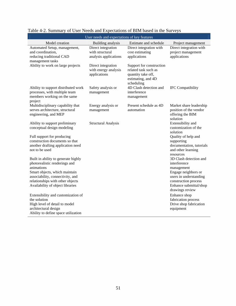
A similar analysis was done with the results from the AECbytes (2007) and Gilligan and
Kunz (2007) surveys studied during the literature review, but in this case the results were
categorized by the modeling capability, building analysis capability, functions for the estimating
and project schedule, and finally functions for the project management. Table 4-2 shows the
results from this categorization.
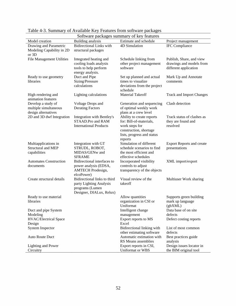
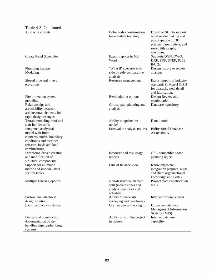
The same categorization done for the user needs and expectations was made for the 33
software packages key features that were identified in Table 4-1, Table 4-3 shows the
categorization of these key features. To perform this categorization an in-depth analysis of the
key features was done to make sure that all the different features available in the market were
included and eliminating those features that were repeated from one software to other.
Once both lists were finished, one with the BIM user needs and expectations and another
with the available features, a unified list was done including both criteria. This unified list
showed 40 baseline questions than were adapted for the different phases of any construction
project (preconstruction, construction, and post construction) where every phase should include
the basic duties that the general contractors perform during any project; preconstruction refers to
the bidding process and preparation process before the physical work starts, construction refers
to the activity of building the project, and post construction to the analysis and deliverables that
the general contractor does after the project is done. This adapted list of 120 questions including
the three phases of the project and then 10 questions covering the general criteria for acquiring
any software represented the foundation for the BIMSEM-GC as showed in Table 4-4.
With the evaluation criteria done, a description of every criteria was required to allow the
company using the model to know the same considerations used during the creation of the
37
model. Tables 4-5 through 4-8 show the description of every criteria and the application of the
concept for every phase during the following analysis.
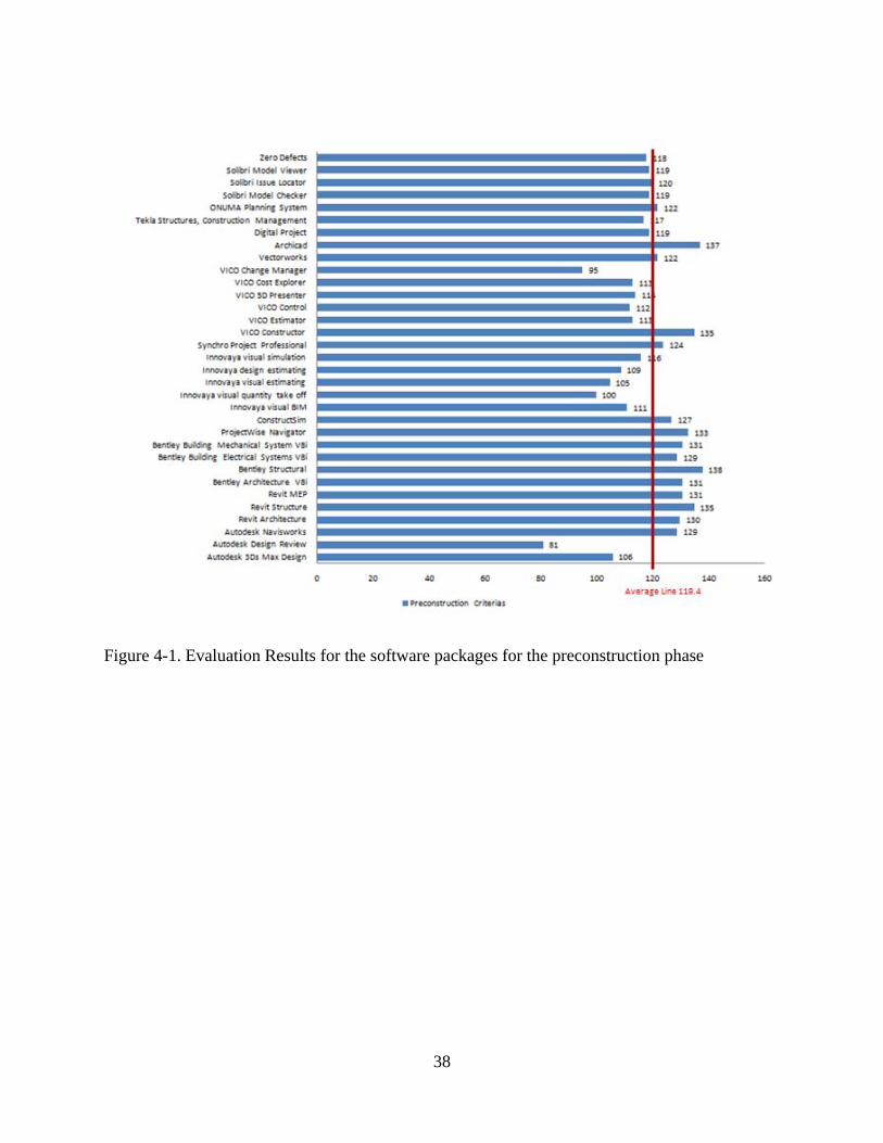
The next step in the analysis was to score the 33 software packages with the BIM
software evaluation criteria shown in Table 4-4. The software packages were scored according to
the authors’ knowledge and the analysis of the key features for every package. From the final
scores for every phase for the different software an important set of results was obtained. The
average score for the 33 software packages in the preconstruction phase was 119.4 point out of
200 (or 59.7%). The average score for the construction phase was 115.9 out of 200 (or 57.9%).
For the post construction phase the average score was 113.2 out of 200 (or 56.6%) showing that
there is still lots of room for improved the BIM technology and more important, that the user
needs and expectations may not yet have been fulfilled.
Figures 4-1 through 4-3 show the scores for every software package considered during
the evaluation process. It should be noted that more than half of the software packages evaluated
are below the average line as shown in Figures 4-1 through 4-3. This may be due to the fact that
some of the evaluated software is part of an integrated solution and the individual program
performance is not as good when analyzing if for use on an entire construction project.
38
Figure 4-1. Evaluation Results for the software packages for the preconstruction phase

39
Figure 4-2. Evaluation Result of the BIM Software Packages for the Construction Phase

40
Figure 4-3. Evaluation Result of the BIM Software Packages for the Post Construction Phase

41
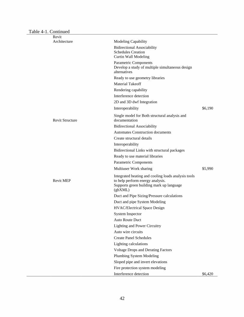
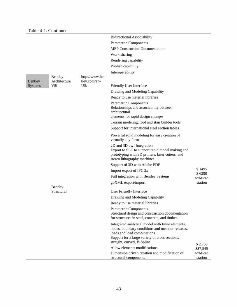
Table 4-1. BIM software packages and key feature
BIM software developers building construction
Company Products Webpage BIM key features Cost per
seat
Autodesk Autodesk 3Ds Max Design
http://usa.autodesk.com/adsk/servlet/index?siteID=123112&id=10326929 Friendly User Interface
$3,990
Drawing and Modeling Capability File Management Utilities Interoperability Parametric Modeling in 2D or 3D Ready to use geometry libraries Polygon Modeling and Texturing Subdivision Surfaces and Polygonal Smoothing High rendering and animation features
Autodesk Design Review
Publish, Share, and view drawings and models from any Autodesk application
n/a Mark Up and Annotate Track and Import Changes
Autodesk Navisworks Interference detection
$9,140
Point/Line Based Clashing
Track status of clashes as they are found and resolved
Export Reports XML import/export 4D Simulation
Schedule linking from other project management software
Set up planned and actual times to visualize deviations from the project schedule
Export 4D simulations into a prerecorded .AVI animation
Create project presentations Rendering capability Interoperability
42
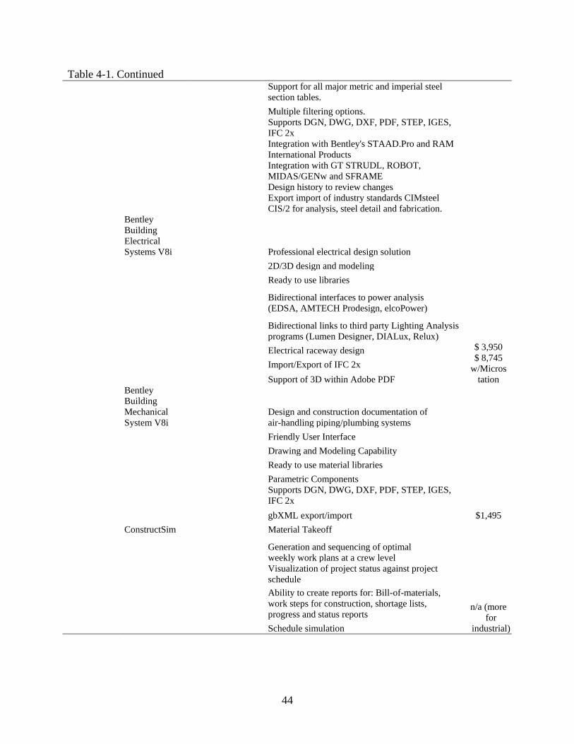
Table 4-1. Continued
Revit Architecture Modeling Capability
$6,190
Bidirectional Associability
Schedules Creation Curtin Wall Modeling
Parametric Components
Develop a study of multiple simultaneous design alternatives
Ready to use geometry libraries Material Takeoff Rendering capability Interference detection 2D and 3D dwf Integration Interoperability
Revit Structure Single model for Both structural analysis and documentation
$5,990
Bidirectional Associability Automates Construction documents Create structural details Interoperability Bidirectional Links with structural packages Ready to use material libraries Parametric Components Multiuser Work sharing
Revit MEP Integrated heating and cooling loads analysis tools to help perform energy analysis.
$6,420
Supports green building mark up language (gbXML)
Duct and Pipe Sizing/Pressure calculations Duct and pipe System Modeling HVAC/Electrical Space Design System Inspector Auto Route Duct Lighting and Power Circuitry Auto wire circuits Create Panel Schedules Lighting calculations Voltage Drops and Derating Factors Plumbing System Modeling Sloped pipe and invert elevations Fire protection system modeling Interference detection
43
Table 4-1. Continued Bidirectional Associability
Parametric Components MEP Construction Documentation Work sharing Rendering capability Publish capability Interoperability
Bentley Systems
Bentley Architecture V8i
http://www.bentley.com/en-US/ Friendly User Interface
$ 1495 $ 6290
w/Micro station
Drawing and Modeling Capability Ready to use material libraries Parametric Components
Relationships and associability between architectural elements for rapid design changes
Terrain modeling, roof and stair builder tools Support for international steel section tables
Powerful solid modeling for easy creation of virtually any form
2D and 3D dwf Integration
Export to SLT to support rapid model making and prototyping with 3D printers, laser cutters, and stereo lithography machines.
Support of 3D with Adobe PDF Import export of IFC 2x Full integration with Bentley Systems gbXML export/import
Bentley Structural User Friendly Interface
$ 2,750 $$7,545w/Micro station
Drawing and Modeling Capability Ready to use material libraries Parametric Components
Structural design and construction documentation for structures in steel, concrete, and timber.
Integrated analytical model with finite elements, nodes, boundary conditions and member releases, loads and load combinations.
Support for a large variety of cross sections, straight, curved, B-Spline.
Allow elements modifications.
Dimension driven creation and modification of structural components
44
Table 4-1. Continued
Support for all major metric and imperial steel section tables.
Multiple filtering options.
Supports DGN, DWG, DXF, PDF, STEP, IGES, IFC 2x
Integration with Bentley's STAAD.Pro and RAM International Products
Integration with GT STRUDL, ROBOT, MIDAS/GENw and SFRAME
Design history to review changes
Export import of industry standards CIMsteel CIS/2 for analysis, steel detail and fabrication.
Bentley Building Electrical Systems V8i Professional electrical design solution
$ 3,950 $ 8,745
w/Microstation
2D/3D design and modeling Ready to use libraries
Bidirectional interfaces to power analysis (EDSA, AMTECH Prodesign, elcoPower)
Bidirectional links to third party Lighting Analysis programs (Lumen Designer, DIALux, Relux)
Electrical raceway design Import/Export of IFC 2x Support of 3D within Adobe PDF
Bentley Building Mechanical System V8i
Design and construction documentation of air-handling piping/plumbing systems
$1,495
Friendly User Interface Drawing and Modeling Capability Ready to use material libraries Parametric Components
Supports DGN, DWG, DXF, PDF, STEP, IGES, IFC 2x
gbXML export/import ConstructSim Material Takeoff
n/a (more for
industrial)
Generation and sequencing of optimal weekly work plans at a crew level
Visualization of project status against project schedule
Ability to create reports for: Bill-of-materials, work steps for construction, shortage lists, progress and status reports
Schedule simulation

45
Table 4-1. Continued
Simulation of different schedule scenarios to find the most efficient and effective schedules
ProjectWise Navigator
http://www.bentley.com/en-US/Products/ProjectWise+Navigator/ Design Review and manipulation
$360
Photorealistic visualization Schedule simulation Clash detection Export Reports
Interoperability: IFC, DGN, DWG, DXF, SKP, PDF, IGES, STEP, etc
History tracking Database repository
Innovaya Innovaya visual BIM
http://www.innovaya.com/
Interactive 3D visualization from architectural desktop or Revit
Incorporated visibility controls to adjust transparency of the objects
Mark Up and Annotate E-mail tools
Innovaya visual quantity take off Material Takeoff
Visual review of the takeoff Allow quantities organization in CSI or Uniformat
Color codes confirmation for quantity takeoff in the building
Associability with Sage Timberline Assembly Intelligent change management Export reports to MS Excel E-mail tools
Innovaya visual estimating Material Takeoff
Visual review of the takeoff Allow quantities organization in CSI or Uniformat
Color codes confirmation for quantity takeoff in the building
Bidirectional link with Sage Timberline Assembly Intelligent change management Export reports to MS Excel Allow the use of MC2 ICE or Timberline database
Innovaya design estimating Automatic estimation with RS Means assemblies
Export reports in CSI, Uniformat or WBS
46
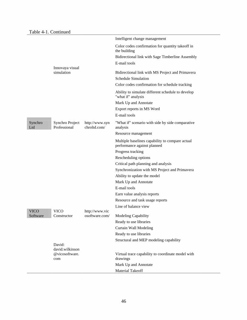
Table 4-1. Continued Intelligent change management
Color codes confirmation for quantity takeoff in the building
Bidirectional link with Sage Timberline Assembly E-mail tools
Innovaya visual simulation Bidirectional link with MS Project and Primavera
Schedule Simulation Color codes confirmation for schedule tracking
Ability to simulate different schedule to develop "what if" analysis
Mark Up and Annotate Export reports in MS Word E-mail tools
Synchro Ltd
Synchro Project Professional
http://www.synchroltd.com/
"What if" scenario with side by side comparative analysis
Resource management
Multiple baselines capability to compare actual performance against planned
Progress tracking Rescheduling options Critical path planning and analysis Synchronization with MS Project and Primavera Ability to update the model Mark Up and Annotate E-mail tools Earn value analysis reports Resource and task usage reports Line of balance view VICO Software
VICO Constructor
http://www.vicosoftware.com/ Modeling Capability
Ready to use libraries Curtain Wall Modeling Ready to use libraries Structural and MEP modeling capability
David: [email protected]
Virtual trace capability to coordinate model with drawings
Mark Up and Annotate Material Takeoff

47
Table 4-1. Continued
Interactive model checker to identify missing quantities
WBS of your project Estimating and scheduling integration
Non-destructive element split (isolate zones and analyze quantities and schedule)
Vico Control integration Data exchange with Primavera and MS Project Ability to place site surveying and benchmark VICO Estimator Recipe based estimating
Cost variances tracking Customizable estimating and scheduling system Ability to split the project in phases Ability to input data manually Ability to separate bid packages
Comparison functionality to compare subcontractors quotes
History tracking Integration with VICO cost manager
Cost tracking capability to perform earn value analysis
VICO Control Ability to input schedule in Gantt or linear format Location breakdown structure Visual dependency network
Ability to create quantity based schedules to see bill of quantities
Resource histogram Control chart color coding Schedule forecast according to real progress inputs Link multiple projects Monte Carlo Risk analysis simulation
Prerequisites check capability (For the procurement)
Micromanagement capability Cost and cash flow capability Look ahead reporting capability Integration with MS Project and Primavera
VICO 5D Presenter 3D, 4D and 5D Views
Ability to present isolated zones Constructability reviews EV analysis
48
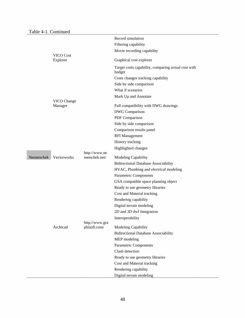
Table 4-1. Continued Record simulation Filtering capability Movie recording capability
VICO Cost Explorer Graphical cost explorer
Target costs capability, comparing actual cost with budget
Costs changes tracking capability Side by side comparison What if scenarios Mark Up and Annotate
VICO Change Manager Full compatibility with DWG drawings
DWG Comparison PDF Comparison Side by side comparison Comparison results panel RFI Management History tracking Highlighted changes
Nemetschek Vectorworks http://www.nemetschek.net/ Modeling Capability
Bidirectional Database Associability HVAC, Plumbing and electrical modeling Parametric Components GSA compatible space planning object Ready to use geometry libraries Cost and Material tracking Rendering capability Digital terrain modeling 2D and 3D dwf Integration Interoperability
Archicad http://www.graphisoft.com/ Modeling Capability
Bidirectional Database Associability MEP modeling Parametric Components Clash detection Ready to use geometry libraries Cost and Material tracking Rendering capability Digital terrain modeling

49
Table 4-1. Continued 2D and 3D dwf Integration Interoperability Gehry Technologies Digital Project
http://www.gehrytechnologies.com/ Design Review and manipulation
4D Planning and coordination Photorealistic visualization 3D 2D viewer Primavera integration Modeling Capability MEP system routing
Knowledgeware integration (capture, reuse, and share organizational knowledge and skills)
Project team collaboration tools Clash detection RFI Management
Tekla Corporation
Tekla Structures, Construction Management
http://www.tekla.com/international/solutions/building-construction /Pages/Default.aspx View Tekla models
Create erection sequences 4D Simulation Assign and manage construction schedule Interoperability: IFC, DWG, DXF, DGN Clash detection Multiple reports Multiuser Work sharing Internet browser viewer Exchange data with MIS systems Material Takeoff
Onuma
ONUMA Planning System
http://www.onuma.com/ Internet database capability
Update cost, bids, planned information in real time Collaboration in real time Model server capability Ability to divide the project in phases Ability to be use in facilities management GIS integration Interoperability IFC open standard
50
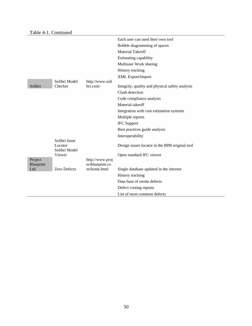
Table 4-1. Continued Each user can used their own tool Bobble diagramming of spaces Material Takeoff Estimating capability Multiuser Work sharing History tracking XML Export/Import
Solibri Solibri Model Checker
http://www.solibri.com/ Integrity, quality and physical safety analysis
Clash detection Code compliance analysis Material takeoff Integration with cost estimation systems Multiple reports IFC Support Best practices guide analysis Interoperability
Solibri Issue Locator Design issues locator in the BIM original tool
Solibri Model Viewer Open standard IFC viewer
Project Blueprint Ltd. Zero Defects
http://www.projectblueprint.com/home.html Single database updated in the internet
History tracking Data base of onsite defects Defect costing reports List of most common defects
51
Table 4-2. Summary of User Needs and Expectations of BIM based in the Surveys User needs and expectations of key features
Model creation Building analysis Estimate and schedule Project management Automated Setup, management, and coordination, reducing traditional CAD management tasks
Direct integration with structural analysis applications
Direct integration with cost estimating applications
Direct integration with project management applications
Ability to work on large projects Direct integration with energy analysis applications
Support for construction related task such as quantity take off, estimating, and 4D scheduling
Ability to support distributed work processes, with multiple team members working on the same project
Safety analysis or management
4D Clash detection and interference management
IFC Compatibility
Multidisciplinary capability that serves architecture, structural engineering, and MEP
Energy analysis or management
Present schedule as 4D automation
Market share leadership position of the vendor offering the BIM solution
Ability to support preliminary conceptual design modeling
Structural Analysis Extensibility and customization of the solution
Full support for producing construction documents so that another drafting application need not to be used
Quality of help and supporting documentation, tutorials and other learning resources
Built in ability to generate highly photorealistic renderings and animations
3D Clash detection and interference management
Smart objects, which maintain associability, connectivity, and relationships with other objects
Engage neighbors or users in understanding construction process
Availability of object libraries Enhance submittal/shop drawings review
Extensibility and customization of the solution
Enhance shop fabrication process
High level of detail to model architectural design
Drive shop fabrication equipment
Ability to define space utilization
52
Table 4-3. Summary of Available Key Features from software packages Software packages summary of key features
Model creation Building analysis Estimate and schedule Project management Drawing and Parametric Modeling Capability in 2D or 3D
Bidirectional Links with structural packages
4D Simulation IFC Compliance
File Management Utilities Integrated heating and cooling loads analysis tools to help perform energy analysis.
Schedule linking from other project management software
Publish, Share, and view drawings and models from different application
Ready to use geometry libraries
Duct and Pipe Sizing/Pressure calculations
Set up planned and actual times to visualize deviations from the project schedule
Mark Up and Annotate comments
High rendering and animation features
Lighting calculations Material Takeoff Track and Import Changes
Develop a study of multiple simultaneous design alternatives
Voltage Drops and Derating Factors
Generation and sequencing of optimal weekly work plans at a crew level
Clash detection
2D and 3D dwf Integration Integration with Bentley's STAAD.Pro and RAM International Products
Ability to create reports for: Bill-of-materials, work steps for construction, shortage lists, progress and status reports
Track status of clashes as they are found and resolved
Multiapplications in Structural and MEP capabilities
Integration with GT STRUDL, ROBOT, MIDAS/GENw and SFRAME
Simulation of different schedule scenarios to find the most efficient and effective schedules
Export Reports and create presentations
Automates Construction documents
Bidirectional interfaces to power analysis (EDSA, AMTECH Prodesign, elcoPower)
Incorporated visibility controls to adjust transparency of the objects
XML import/export
Create structural details Bidirectional links to third party Lighting Analysis programs (Lumen Designer, DIALux, Relux)
Visual review of the takeoff
Multiuser Work sharing
Ready to use material libraries
Allow quantities organization in CSI or Uniformat
Supports green building mark up language (gbXML)
Duct and pipe System Modeling
Intelligent change management
Data base of on site defects
HVAC/Electrical Space Design
Export reports to MS Excel
Defect costing reports
System Inspector Bidirectional linking with other estimating software
List of most common defects
Auto Route Duct Automatic estimation with RS Means assemblies
Best practices guide analysis
Lighting and Power Circuitry
Export reports in CSI, Uniformat or WBS
Design issues locator in the BIM original tool
53
Table 4-3. Continued Auto wire circuits Color codes confirmation
for schedule tracking Export to SLT to support rapid model making and prototyping with 3D printers, laser cutters, and stereo lithography machines.
Create Panel Schedules Export reports in MS Word
Supports DGN, DWG, DXF, PDF, STEP, IGES, IFC 2x
Plumbing System Modeling
"What if" scenario with side by side comparative analysis
Design history to review changes
Sloped pipe and invert elevations
Resource management Export import of industry standards CIMsteel CIS/2 for analysis, steel detail and fabrication.
Fire protection system modeling
Rescheduling options Design Review and manipulation
Relationships and associability between architectural elements for rapid design changes
Critical path planning and analysis
Database repository
Terrain modeling, roof and stair builder tools
Ability to update the model
E-mail tools
Integrated analytical model with finite elements, nodes, boundary conditions and member releases, loads and load combinations.
Earn value analysis reports Bidirectional Database Associability
Dimension driven creation and modification of structural components
Resource and task usage reports
GSA compatible space planning object
Support for all major metric and imperial steel section tables.
Line of balance view Knowledgeware integration (capture, reuse, and share organizational knowledge and skills)
Multiple filtering options. Non-destructive element split (isolate zones and analyze quantities and schedule)
Project team collaboration tools
Professional electrical design solution
Ability to place site surveying and benchmark
Internet browser viewer
Electrical raceway design Cost variances tracking Exchange data with Management Information Systems (MIS)
Design and construction documentation of air-handling piping/plumbing systems
Ability to split the project in phases
Internet database capability

54
Table 4-3. Continued Curtain Wall Modeling Ability to input data
manually Integrity, quality and physical safety analysis
Virtual trace capability to coordinate model with drawings
Ability to separate bid packages
Code compliance analysis
Comparison functionality to compare subcontractors quotes
Ability to input schedule in Gantt or linear format
Location breakdown structure
Visual dependency network
Resource histogram Control chart color coding Schedule forecast
according to real progress inputs
Link multiple projects Monte Carlo Risk analysis
simulation
Prerequisites check capability (For the procurement)
Look ahead reporting capability
Side by side geometric comparison
Comparison results panel RFI Management Create erection sequences
55
Table 4-4. BIM Software Evaluation Criteria
Software evaluation model for GC
Date: 26-Feb-09
Company: C1
Criteria Company's Needs
30% Preconstruction criteria Model creation
Ability to Automated Setup, management, and coordination Drawing and Modeling Capability Parametric Modeling capability in 2D & 3D Ready to use libraries
Built in ability to generate photorealistic renderings and
animations
Smart objects, which maintain associability, connectivity, and
relationships with other objects Ability to publish, share and view drawings and models Ability to track history to review changes Multiuser work sharing capability Ability to work on large projects
Multidisciplinary capability that serves architecture, structural
engineering, and MEP Ability to support preliminary conceptual design modeling High level of detail to model architectural design
Full support for producing construction documents so that
another drafting application need not to be used Building Analysis Direct integration with structural analysis applications Direct integration with energy analysis applications Ability to define space utilization Structural Analysis Safety analysis or management Energy analysis or management 3D Clash detection and interference management Estimate and schedule Direct integration with cost estimating applications Direct integration with project schedule applications Ability to create quantity take off Ability to create estimates 4D Clash detection and interference management 5D Analysis or management
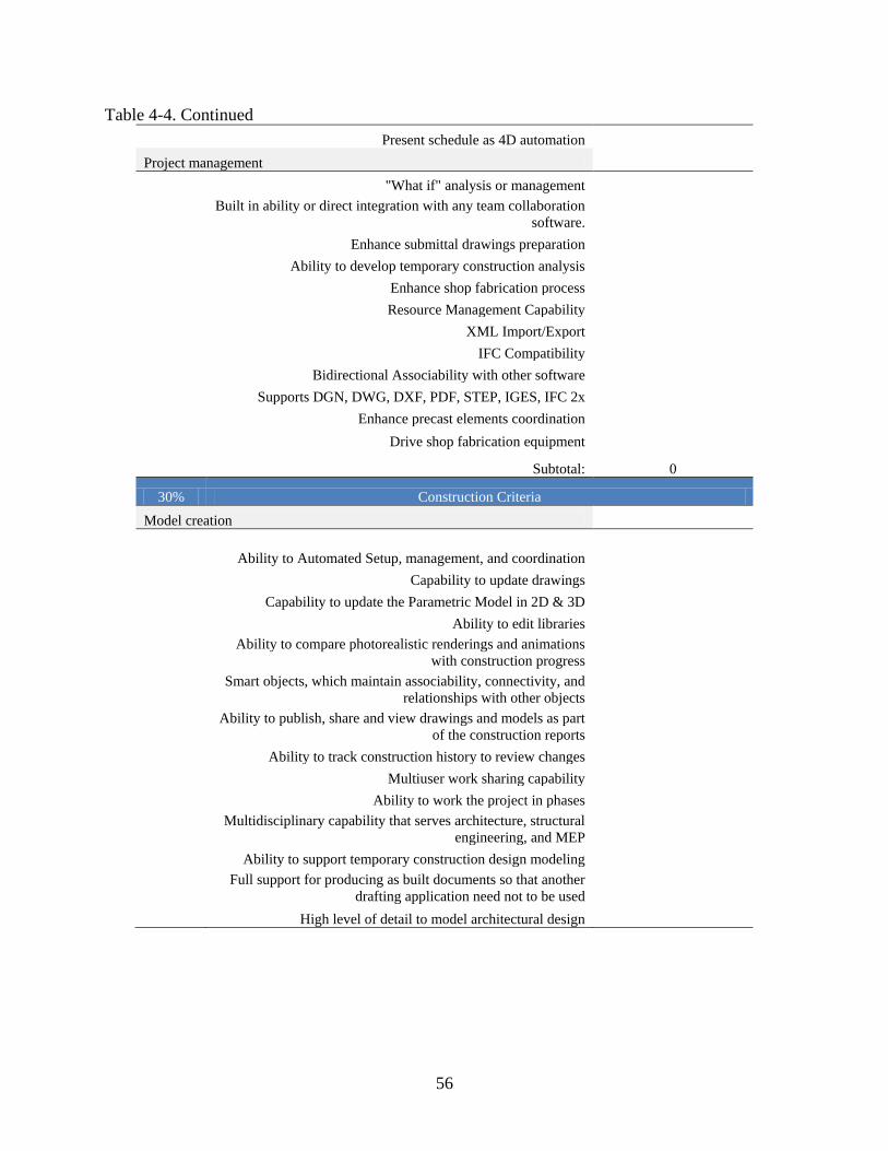
56
Table 4-4. Continued Present schedule as 4D automation Project management "What if" analysis or management
Built in ability or direct integration with any team collaboration
software. Enhance submittal drawings preparation Ability to develop temporary construction analysis Enhance shop fabrication process Resource Management Capability XML Import/Export IFC Compatibility Bidirectional Associability with other software Supports DGN, DWG, DXF, PDF, STEP, IGES, IFC 2x Enhance precast elements coordination Drive shop fabrication equipment
Subtotal: 0
30% Construction Criteria Model creation
Ability to Automated Setup, management, and coordination Capability to update drawings Capability to update the Parametric Model in 2D & 3D Ability to edit libraries
Ability to compare photorealistic renderings and animations
with construction progress
Smart objects, which maintain associability, connectivity, and
relationships with other objects
Ability to publish, share and view drawings and models as part
of the construction reports Ability to track construction history to review changes Multiuser work sharing capability Ability to work the project in phases
Multidisciplinary capability that serves architecture, structural
engineering, and MEP Ability to support temporary construction design modeling
Full support for producing as built documents so that another
drafting application need not to be used High level of detail to model architectural design

57
Table 4-4. Continued Building analysis Direct integration with structural analysis applications Direct integration with energy analysis applications Ability to manage updates in the space utilization Structural analysis or management Energy analysis or management Safety analysis or management
3D Clash detection and interference management with real
progress Estimate and schedule Direct integration with cost estimating applications Direct integration with project schedule applications Ability to update quantity take off Ability to keep track of budget
4D Clash detection and interference management with real
progress 5D Analysis or management with real progress Update schedule as 4D automation Project management "What if" analysis or management
Built in ability or direct integration with any team collaboration
software. Tracking of submittal drawings status Ability to update temporary construction progress Update shop fabrication process Resource Tracking Capability XML Import/Export IFC Compatibility Bidirectional Associability with other software Supports DGN, DWG, DXF, PDF, STEP, IGES, IFC 2x Enhance precast elements installation Drive shop fabrication equipment Sub Total: 0
30% Post construction criteria Model creation
Ability to Automated Setup, management, and coordination Capability to create as built drawings Capability to create as built Parametric Model in 2D & 3D
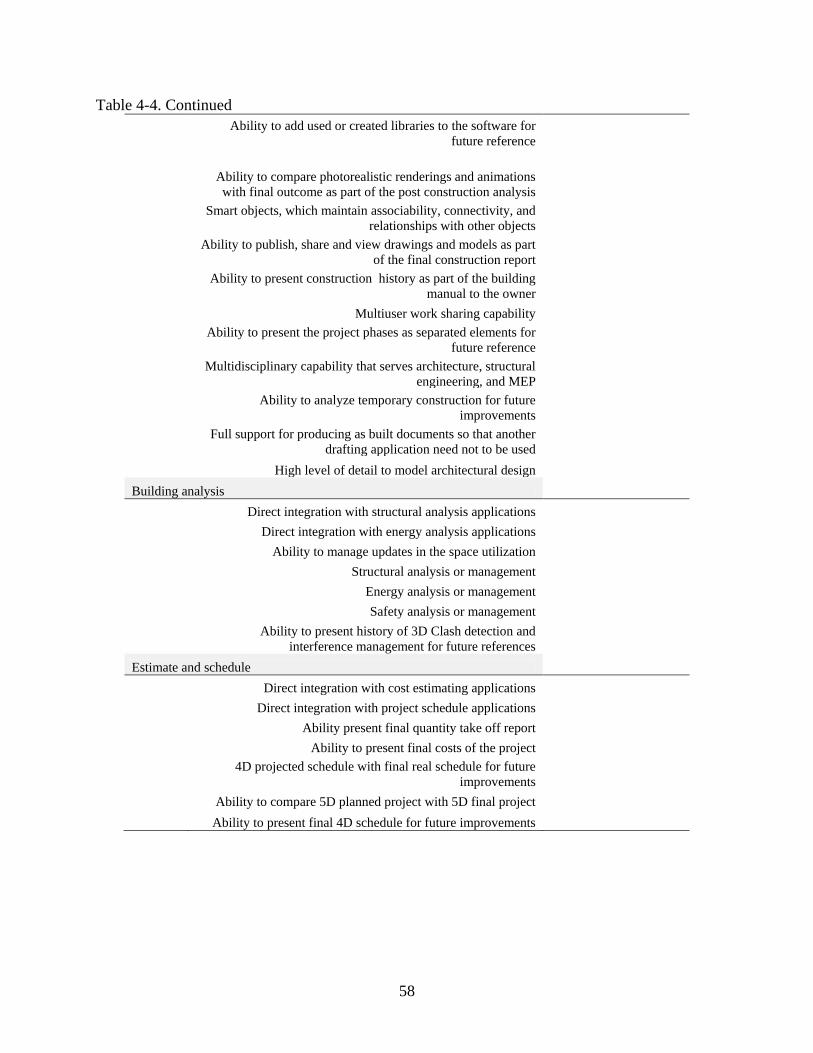
58
Table 4-4. Continued
Ability to add used or created libraries to the software for
future reference
Ability to compare photorealistic renderings and animations with final outcome as part of the post construction analysis
Smart objects, which maintain associability, connectivity, and
relationships with other objects
Ability to publish, share and view drawings and models as part
of the final construction report
Ability to present construction history as part of the building
manual to the owner Multiuser work sharing capability
Ability to present the project phases as separated elements for
future reference
Multidisciplinary capability that serves architecture, structural
engineering, and MEP
Ability to analyze temporary construction for future
improvements
Full support for producing as built documents so that another
drafting application need not to be used High level of detail to model architectural design Building analysis Direct integration with structural analysis applications Direct integration with energy analysis applications Ability to manage updates in the space utilization Structural analysis or management Energy analysis or management Safety analysis or management
Ability to present history of 3D Clash detection and
interference management for future references Estimate and schedule Direct integration with cost estimating applications Direct integration with project schedule applications Ability present final quantity take off report Ability to present final costs of the project
4D projected schedule with final real schedule for future
improvements Ability to compare 5D planned project with 5D final project Ability to present final 4D schedule for future improvements

59
Table 4-4. Continued Project management
Ability to compare all the "What if" analysis for future
improvements
Built in ability or direct integration with any team collaboration
software.
Ability to present final submittal to present as part of the owner
report
Ability to present all real temporary construction progress for
future improvements
Present as built shop fabrication process for future
improvements
Ability to present Resource Utilization history for future
improvements XML Import/Export IFC Compatibility Bidirectional Associability with other software Supports DGN, DWG, DXF, PDF, STEP, IGES, IFC 2x
Ability to analyze precast elements installation for future
improvements
Ability to present shop fabrication equipment production rate
for future improvements Sub Total: 0
10% General criteria
Market share leadership position of the vendor offering the
BIM solution
Quality of help and supporting documentation, tutorials and
other learning resources Extensibility and customization of the solution
Engage neighbors or users in understanding construction
process Cost of the implementation
Recovery mechanism ensures data integrity to the business
function level.
Operates in preferred operating environment (e.g., Windows,
UNIX). Necessary upgrades to the company's system Ownership of components clearly define
Number of third party developers developing add on
applications for the tool Sub Total: 0
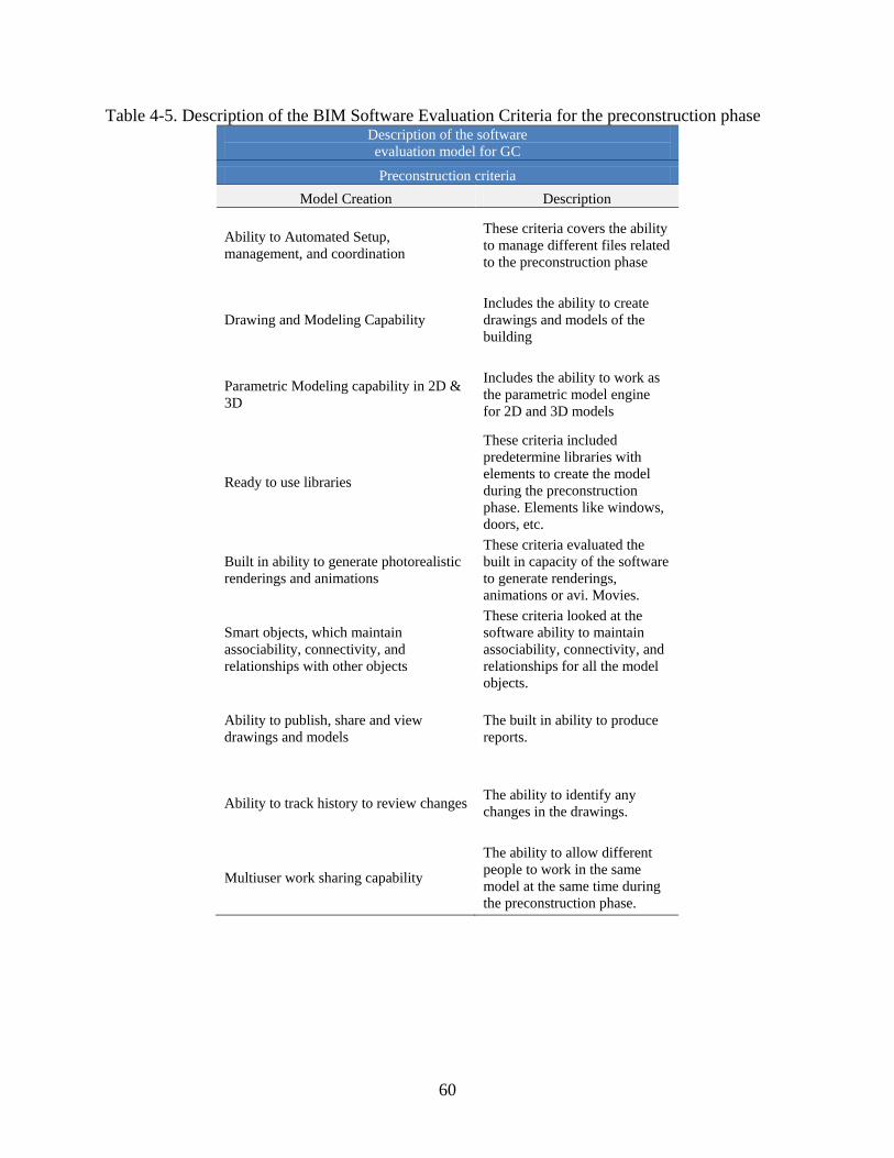
60
Table 4-5. Description of the BIM Software Evaluation Criteria for the preconstruction phase Description of the software evaluation model for GC
Preconstruction criteria Model Creation Description
Ability to Automated Setup, management, and coordination
These criteria covers the ability to manage different files related to the preconstruction phase
Drawing and Modeling Capability Includes the ability to create drawings and models of the building
Parametric Modeling capability in 2D & 3D
Includes the ability to work as the parametric model engine for 2D and 3D models
Ready to use libraries
These criteria included predetermine libraries with elements to create the model during the preconstruction phase. Elements like windows, doors, etc.
Built in ability to generate photorealistic renderings and animations
These criteria evaluated the built in capacity of the software to generate renderings, animations or avi. Movies.
Smart objects, which maintain associability, connectivity, and relationships with other objects
These criteria looked at the software ability to maintain associability, connectivity, and relationships for all the model objects.
Ability to publish, share and view drawings and models
The built in ability to produce reports.
Ability to track history to review changes The ability to identify any changes in the drawings.
Multiuser work sharing capability
The ability to allow different people to work in the same model at the same time during the preconstruction phase.
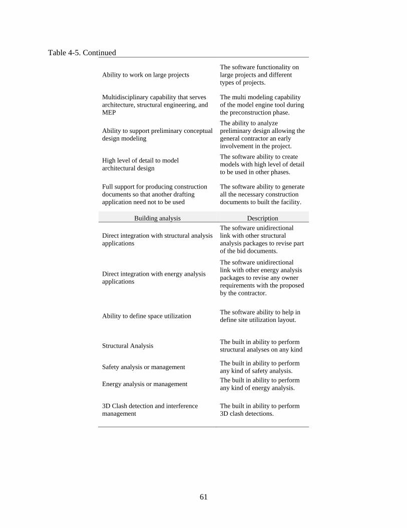
61
Table 4-5. Continued
Ability to work on large projects The software functionality on large projects and different types of projects.
Multidisciplinary capability that serves architecture, structural engineering, and MEP
The multi modeling capability of the model engine tool during the preconstruction phase.
Ability to support preliminary conceptual design modeling
The ability to analyze preliminary design allowing the general contractor an early involvement in the project.
High level of detail to model architectural design
The software ability to create models with high level of detail to be used in other phases.
Full support for producing construction documents so that another drafting application need not to be used
The software ability to generate all the necessary construction documents to built the facility.
Building analysis Description
Direct integration with structural analysis applications
The software unidirectional link with other structural analysis packages to revise part of the bid documents.
Direct integration with energy analysis applications
The software unidirectional link with other energy analysis packages to revise any owner requirements with the proposed by the contractor.
Ability to define space utilization The software ability to help in define site utilization layout.
Structural Analysis The built in ability to perform structural analyses on any kind
Safety analysis or management The built in ability to perform any kind of safety analysis.
Energy analysis or management The built in ability to perform any kind of energy analysis.
3D Clash detection and interference management
The built in ability to perform 3D clash detections.
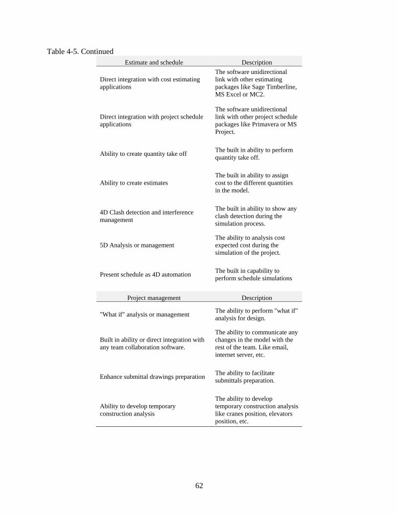
62
Table 4-5. Continued Estimate and schedule Description
Direct integration with cost estimating applications
The software unidirectional link with other estimating packages like Sage Timberline, MS Excel or MC2.
Direct integration with project schedule applications
The software unidirectional link with other project schedule packages like Primavera or MS Project.
Ability to create quantity take off The built in ability to perform quantity take off.
Ability to create estimates The built in ability to assign cost to the different quantities in the model.
4D Clash detection and interference management
The built in ability to show any clash detection during the simulation process.
5D Analysis or management The ability to analysis cost expected cost during the simulation of the project.
Present schedule as 4D automation The built in capability to perform schedule simulations
Project management Description
"What if" analysis or management The ability to perform "what if" analysis for design.
Built in ability or direct integration with any team collaboration software.
The ability to communicate any changes in the model with the rest of the team. Like email, internet server, etc.
Enhance submittal drawings preparation The ability to facilitate submittals preparation.
Ability to develop temporary construction analysis
The ability to develop temporary construction analysis like cranes position, elevators position, etc.
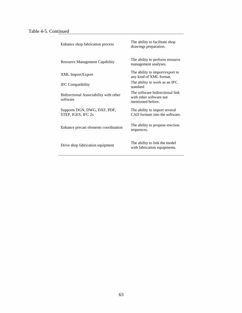
63
Table 4-5. Continued
Enhance shop fabrication process The ability to facilitate shop drawings preparation.
Resource Management Capability The ability to perform resource management analyses.
XML Import/Export The ability to import/export to any kind of XML format.
IFC Compatibility The ability to work as an IFC standard
Bidirectional Associability with other software
The software bidirectional link with other software not mentioned before.
Supports DGN, DWG, DXF, PDF, STEP, IGES, IFC 2x
The ability to import several CAD formats into the software.
Enhance precast elements coordination The ability to propose erection sequences.
Drive shop fabrication equipment The ability to link the model with fabrication equipments.
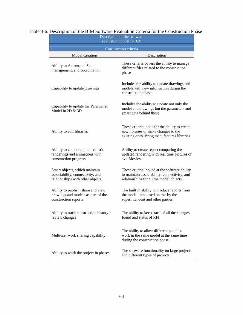
64
Table 4-6. Description of the BIM Software Evaluation Criteria for the Construction Phase Description of the software evaluation model for GC
Construction criteria Model Creation Description
Ability to Automated Setup, management, and coordination
These criteria covers the ability to manage different files related to the construction phase
Capability to update drawings Includes the ability to update drawings and models with new information during the construction phase.
Capability to update the Parametric Model in 2D & 3D
Includes the ability to update not only the model and drawings but the parameters and smart data behind those.
Ability to edit libraries These criteria looks for the ability to create new libraries or make changes to the existing ones. Bring manufactures libraries.
Ability to compare photorealistic renderings and animations with construction progress
Ability to create report comparing the updated rendering with real time pictures or avi. Movies.
Smart objects, which maintain associability, connectivity, and relationships with other objects
These criteria looked at the software ability to maintain associability, connectivity, and relationships for all the model objects.
Ability to publish, share and view drawings and models as part of the construction reports
The built in ability to produce reports from the model to be used on site by the superintendent and other parties.
Ability to track construction history to review changes
The ability to keep track of all the changes found and status of RFI.
Multiuser work sharing capability The ability to allow different people to work in the same model at the same time during the construction phase.
Ability to work the project in phases The software functionality on large projects and different types of projects.
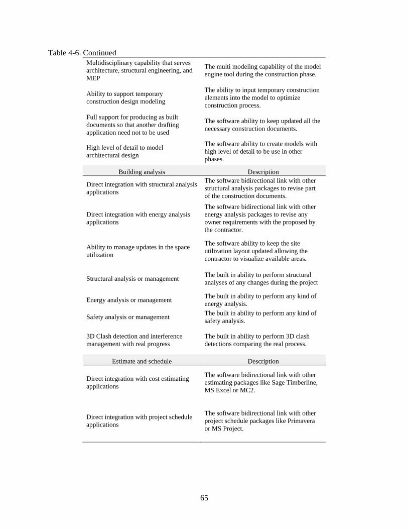
65
Table 4-6. Continued Multidisciplinary capability that serves architecture, structural engineering, and MEP
The multi modeling capability of the model engine tool during the construction phase.
Ability to support temporary construction design modeling
The ability to input temporary construction elements into the model to optimize construction process.
Full support for producing as built documents so that another drafting application need not to be used
The software ability to keep updated all the necessary construction documents.
High level of detail to model architectural design
The software ability to create models with high level of detail to be use in other phases.
Building analysis Description
Direct integration with structural analysis applications
The software bidirectional link with other structural analysis packages to revise part of the construction documents.
Direct integration with energy analysis applications
The software bidirectional link with other energy analysis packages to revise any owner requirements with the proposed by the contractor.
Ability to manage updates in the space utilization
The software ability to keep the site utilization layout updated allowing the contractor to visualize available areas.
Structural analysis or management The built in ability to perform structural analyses of any changes during the project
Energy analysis or management The built in ability to perform any kind of energy analysis.
Safety analysis or management The built in ability to perform any kind of safety analysis.
3D Clash detection and interference management with real progress
The built in ability to perform 3D clash detections comparing the real process.
Estimate and schedule Description
Direct integration with cost estimating applications
The software bidirectional link with other estimating packages like Sage Timberline, MS Excel or MC2.
Direct integration with project schedule applications
The software bidirectional link with other project schedule packages like Primavera or MS Project.
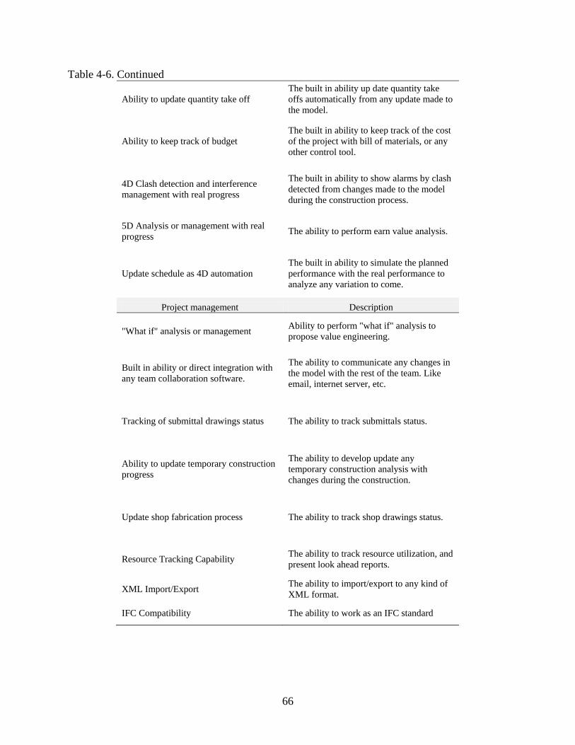
66
Table 4-6. Continued
Ability to update quantity take off The built in ability up date quantity take offs automatically from any update made to the model.
Ability to keep track of budget The built in ability to keep track of the cost of the project with bill of materials, or any other control tool.
4D Clash detection and interference management with real progress
The built in ability to show alarms by clash detected from changes made to the model during the construction process.
5D Analysis or management with real progress The ability to perform earn value analysis.
Update schedule as 4D automation The built in ability to simulate the planned performance with the real performance to analyze any variation to come.
Project management Description
"What if" analysis or management Ability to perform "what if" analysis to propose value engineering.
Built in ability or direct integration with any team collaboration software.
The ability to communicate any changes in the model with the rest of the team. Like email, internet server, etc.
Tracking of submittal drawings status The ability to track submittals status.
Ability to update temporary construction progress
The ability to develop update any temporary construction analysis with changes during the construction.
Update shop fabrication process The ability to track shop drawings status.
Resource Tracking Capability The ability to track resource utilization, and present look ahead reports.
XML Import/Export The ability to import/export to any kind of XML format.
IFC Compatibility The ability to work as an IFC standard

67
Table 4-6. Continued
Bidirectional Associability with other software
The software bidirectional link with other software not mentioned before.
Supports DGN, DWG, DXF, PDF, STEP, IGES, IFC 2x
The ability to import several CAD formats into the software.
Enhance precast elements installation The ability to optimize erection sequences.
Drive shop fabrication equipment The ability to change any fabrication order during the construction process as a change order.
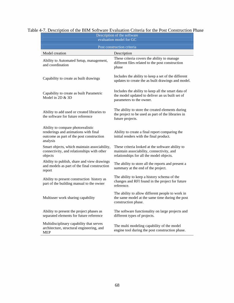
68
Table 4-7. Description of the BIM Software Evaluation Criteria for the Post Construction Phase Description of the software evaluation model for GC
Post construction criteria Model creation Description
Ability to Automated Setup, management, and coordination
These criteria covers the ability to manage different files related to the post construction phase
Capability to create as built drawings Includes the ability to keep a set of the different updates to create the as built drawings and model.
Capability to create as built Parametric Model in 2D & 3D
Includes the ability to keep all the smart data of the model updated to deliver an us built set of parameters to the owner.
Ability to add used or created libraries to the software for future reference
The ability to store the created elements during the project to be used as part of the libraries in future projects.
Ability to compare photorealistic renderings and animations with final outcome as part of the post construction analysis
Ability to create a final report comparing the initial renders with the final product.
Smart objects, which maintain associability, connectivity, and relationships with other objects
These criteria looked at the software ability to maintain associability, connectivity, and relationships for all the model objects.
Ability to publish, share and view drawings and models as part of the final construction report
The ability to store all the reports and present a summary at the end of the project.
Ability to present construction history as part of the building manual to the owner
The ability to keep a history schema of the changes and RFI found in the project for future reference.
Multiuser work sharing capability The ability to allow different people to work in the same model at the same time during the post construction phase.
Ability to present the project phases as separated elements for future reference
The software functionality on large projects and different types of projects.
Multidisciplinary capability that serves architecture, structural engineering, and MEP
The multi modeling capability of the model engine tool during the post construction phase.
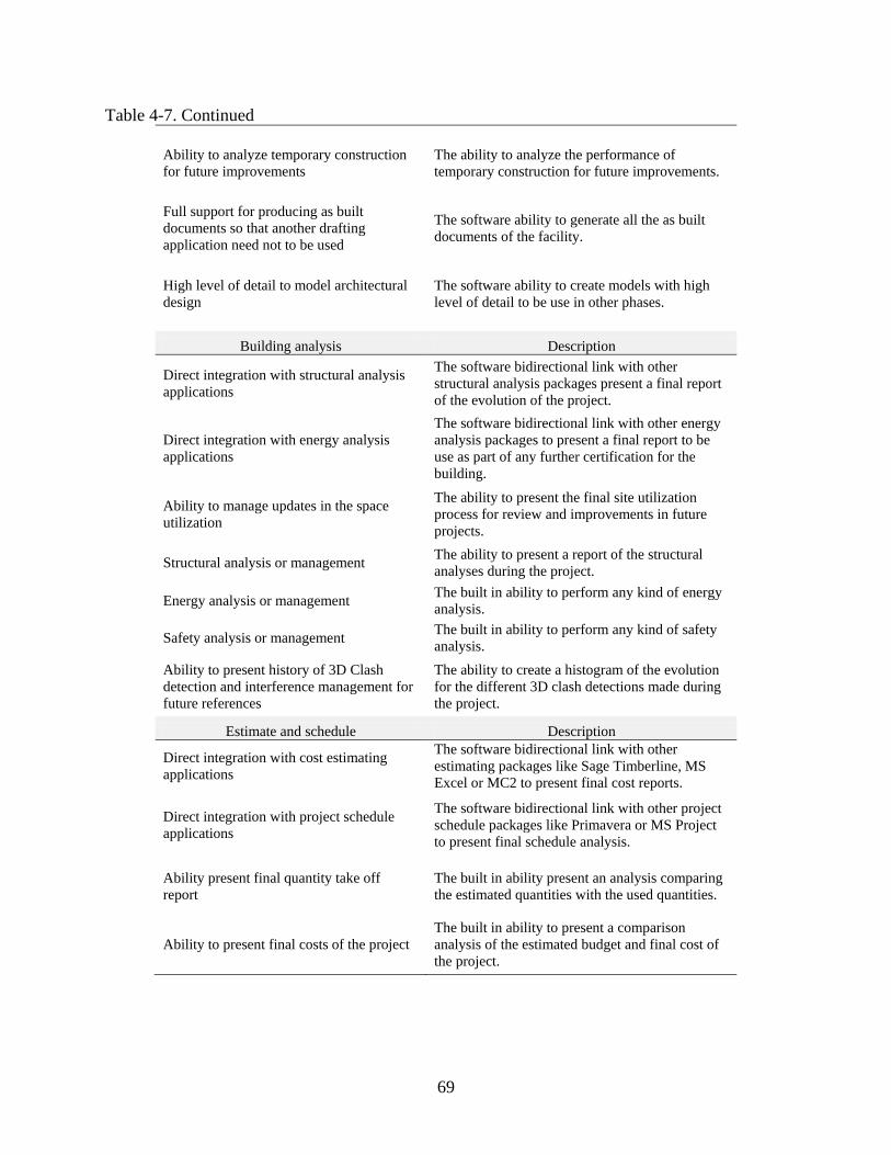
69
Table 4-7. Continued
Ability to analyze temporary construction for future improvements
The ability to analyze the performance of temporary construction for future improvements.
Full support for producing as built documents so that another drafting application need not to be used
The software ability to generate all the as built documents of the facility.
High level of detail to model architectural design
The software ability to create models with high level of detail to be use in other phases.
Building analysis Description
Direct integration with structural analysis applications
The software bidirectional link with other structural analysis packages present a final report of the evolution of the project.
Direct integration with energy analysis applications
The software bidirectional link with other energy analysis packages to present a final report to be use as part of any further certification for the building.
Ability to manage updates in the space utilization
The ability to present the final site utilization process for review and improvements in future projects.
Structural analysis or management The ability to present a report of the structural analyses during the project.
Energy analysis or management The built in ability to perform any kind of energy analysis.
Safety analysis or management The built in ability to perform any kind of safety analysis.
Ability to present history of 3D Clash detection and interference management for future references
The ability to create a histogram of the evolution for the different 3D clash detections made during the project.
Estimate and schedule Description
Direct integration with cost estimating applications
The software bidirectional link with other estimating packages like Sage Timberline, MS Excel or MC2 to present final cost reports.
Direct integration with project schedule applications
The software bidirectional link with other project schedule packages like Primavera or MS Project to present final schedule analysis.
Ability present final quantity take off report
The built in ability present an analysis comparing the estimated quantities with the used quantities.
Ability to present final costs of the project The built in ability to present a comparison analysis of the estimated budget and final cost of the project.
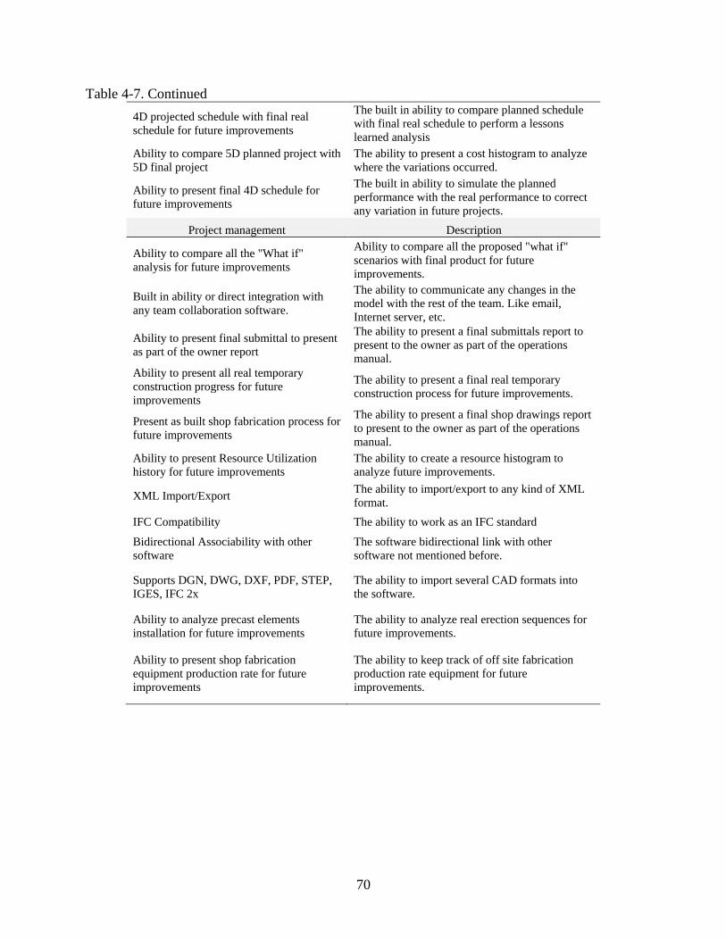
70
Table 4-7. Continued 4D projected schedule with final real schedule for future improvements
The built in ability to compare planned schedule with final real schedule to perform a lessons learned analysis
Ability to compare 5D planned project with 5D final project
The ability to present a cost histogram to analyze where the variations occurred.
Ability to present final 4D schedule for future improvements
The built in ability to simulate the planned performance with the real performance to correct any variation in future projects.
Project management Description
Ability to compare all the "What if" analysis for future improvements
Ability to compare all the proposed "what if" scenarios with final product for future improvements.
Built in ability or direct integration with any team collaboration software.
The ability to communicate any changes in the model with the rest of the team. Like email, Internet server, etc.
Ability to present final submittal to present as part of the owner report
The ability to present a final submittals report to present to the owner as part of the operations manual.
Ability to present all real temporary construction progress for future improvements
The ability to present a final real temporary construction process for future improvements.
Present as built shop fabrication process for future improvements
The ability to present a final shop drawings report to present to the owner as part of the operations manual.
Ability to present Resource Utilization history for future improvements
The ability to create a resource histogram to analyze future improvements.
XML Import/Export The ability to import/export to any kind of XML format.
IFC Compatibility The ability to work as an IFC standard
Bidirectional Associability with other software
The software bidirectional link with other software not mentioned before.
Supports DGN, DWG, DXF, PDF, STEP, IGES, IFC 2x
The ability to import several CAD formats into the software.
Ability to analyze precast elements installation for future improvements
The ability to analyze real erection sequences for future improvements.
Ability to present shop fabrication equipment production rate for future improvements
The ability to keep track of off site fabrication production rate equipment for future improvements.
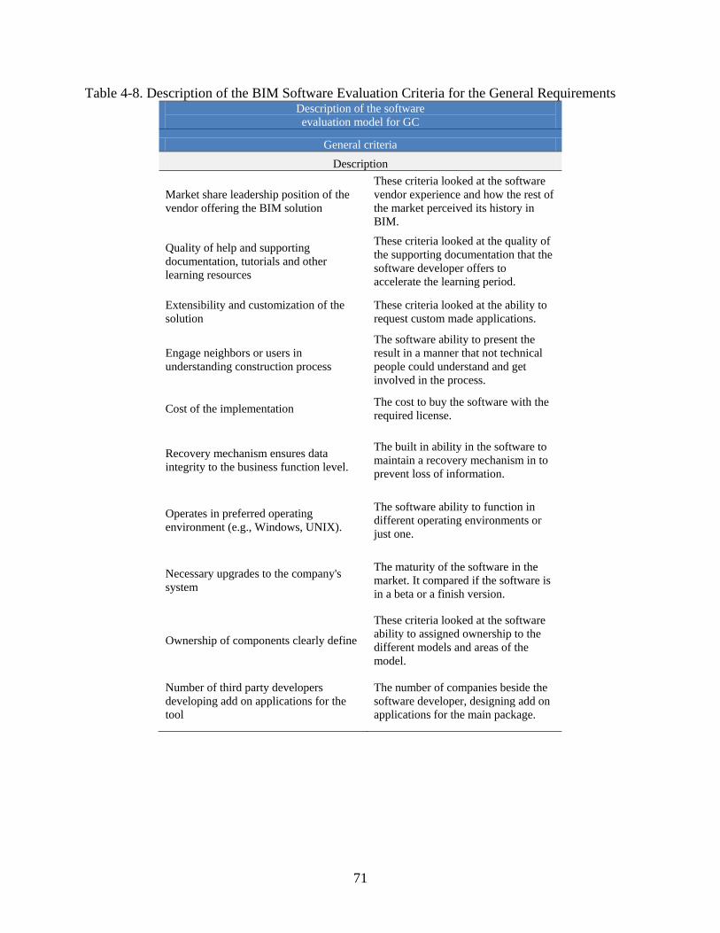
71
Table 4-8. Description of the BIM Software Evaluation Criteria for the General Requirements Description of the software evaluation model for GC
General criteria Description
Market share leadership position of the vendor offering the BIM solution
These criteria looked at the software vendor experience and how the rest of the market perceived its history in BIM.
Quality of help and supporting documentation, tutorials and other learning resources
These criteria looked at the quality of the supporting documentation that the software developer offers to accelerate the learning period.
Extensibility and customization of the solution
These criteria looked at the ability to request custom made applications.
Engage neighbors or users in understanding construction process
The software ability to present the result in a manner that not technical people could understand and get involved in the process.
Cost of the implementation The cost to buy the software with the required license.
Recovery mechanism ensures data integrity to the business function level.
The built in ability in the software to maintain a recovery mechanism in to prevent loss of information.
Operates in preferred operating environment (e.g., Windows, UNIX).
The software ability to function in different operating environments or just one.
Necessary upgrades to the company's system
The maturity of the software in the market. It compared if the software is in a beta or a finish version.
Ownership of components clearly define
These criteria looked at the software ability to assigned ownership to the different models and areas of the model.
Number of third party developers developing add on applications for the tool
The number of companies beside the software developer, designing add on applications for the main package.
72
CHAPTER 5 BIM SOFTWARE EVALUATION MODEL
Once the baseline of the model was created the next step was to create the evaluation
criteria to recommend the top five software packages according to the company’s responses to
the created criteria. This chapter presents a detailed explanation of how the BIM Software
Evaluation Model for General Contractors (BIMSEM-GC) works taking into consideration the
steps involved in using the model and the required programming language to make the model
work.
The model needed to be a simple and easy to use and also take into consideration that
when a contractor is using the BIMSEM-GC as part of the implementation process, the
contractor is starting to acquire knowledge in the subject. This is why MS Excel was selected as
the platform to develop the BIMSEM-GC and also the fact that almost every contractor uses MS
Excel nowadays as part of their operations was taken into consideration.
The BIMSEM-GC consists of one main spread sheet called “model” where the selection
criteria questions will appear in blank to be filled out by the contractor. The questions are filled
out using the same 5-point Likert scale that was used to score the 33 software packages as shown
in Figure 5-1. By clicking in the cell the 5-point Likert scale will appear for every question of the
evaluation criteria for every phase. The BIMSEM-GC will only display the specified values from
1 to 5 with 1 being the least important and 5 the most important. The model will also display a
warning message if the user inputs a value out of the range and will not allow the user to
continue with the evaluation until the value is changed.
Once the contractor has answered every question for the preconstruction, construction,
post construction, and general criteria the next step is to click the button called
“Recommendation” shown in Figure 5-2. By clicking that button the model will start with the

73
calculation process analyzing the company responses and trying to match those responses with
the most appropriate software for those needs.
The BIMSEM-GC will display the top five solutions for every phase, preconstruction,
construction, post construction, and general criteria. Figures 5-3 through 5-6 show the name of
the most appropriate software package and the given scores for all criteria used by the author,
therefore the user will be able to compare every individual score for every recommendation. The
recommended software packages for every phase are listed from left to right, with the first one
being the one that best fits the company’s needs and the last one is the fifth recommendation
form the 33 software packages that the model evaluated.
Additionally, the BIMSEM will also display a graph showing the company’s
performance according to the responses for the criteria and its performance on the combination
of the recommendations as shown in Figure 5-7. This will allow the user to determine how well
the recommendation is adapted to the company’s needs, supporting even more the final selection
of the BIM software.
Figure 5-8, shows company’s BIM software needs according to the user of the model
responses. The BIM model will compare the company’s results with the maximum possible
scores, also showing if there is a deficiency in any area when implementing BIM. The model
should be as balanced as possible, assuming that the company is trying to implement BIM in all
the phases of the project. If the company is only implementing BIM in one specific area then the
model graph should bias the results to that area, allowing the company to see if any effort is
being wasted in any other area where the implementation is not desired.
The final results (See Figures 5-9 to 5-12) shows the recommended software packages
and the company’s assessment of its level of need by the subtotal score for every evaluation
74
phase. At this point the user will be able to compare the subtotal score of every package with the
subtotal score for the company, supporting one more time the final decision when implementing
the software.
The results from testing the BIMSEM-GC model for different possible scenarios
determines that there is no single software package that satisfies the needs of a random company
for every phase of the project. Most of the times the results will vary from phase to phase and no
software package will completely satisfy all the company’s needs, there is always a deficiency
for some area or some phase of the project. This supports the idea that the best option when
implementing BIM in all the project processes is it to consider the implementation of a suite of
products that together will cover the most areas of the project workflow.
How does the Model Work? : Thus far the data required to develop the model and to use
the model have been explained. Next the description of the process of how the BIMSEM-GC is
able to recommend the most appropriate software for every phase while trying to consider every
company needs is discussed. The evaluation process for in the model is as follows:
• First the individual software packages scores and the company’s needs score are compiled by looking at the subtotal for every phase. The software packages and the company’s subtotal are listed in column to then calculate the difference between every software subtotal to the company subtotal for every phase.
• The next step is to calculate the absolute value of every difference and sort the software packages list by the smallest to the largest difference allowing to identify the closest software packages to the company’s needs.
• The coefficient of variation at the 95% confidence level is then calculated for every software package and then the company’s coefficient of variation is also calculated. Then the difference between the company’s needs coefficient of variation and every software package’s coefficient of variation is calculated. This will allow the model to select the solution with the most similar behavior according to the company’s needs.
• The final process was to sort the software packages listed by the smallest to the largest absolute difference for the coefficient of variation. Then the top five names for every phase are recommended in the “model” spread sheet.

75
This whole process was programmed by using MS Visual Basic to facilitate the use of the
BIMSEM-GC and the program coding is shown in Appendix A.
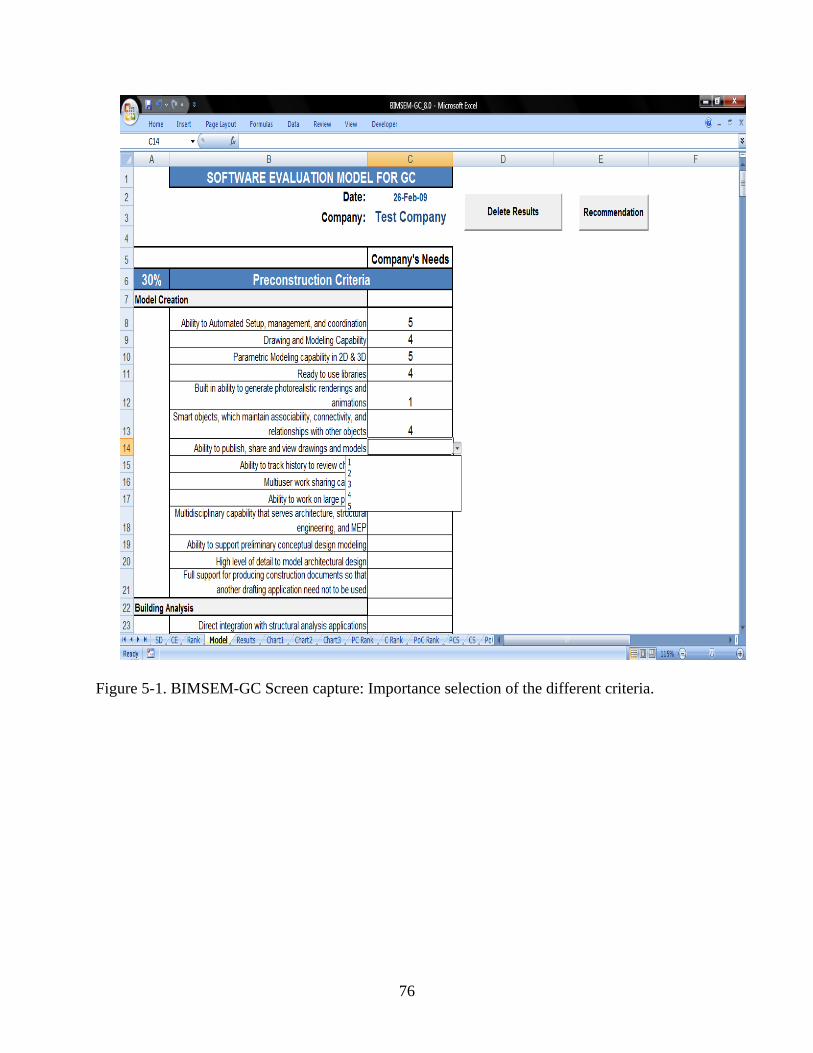
76
Figure 5-1. BIMSEM-GC Screen capture: Importance selection of the different criteria.

77
Figure 5-2. BIMSEM-GC Screen capture: Before clicking the recommendation button
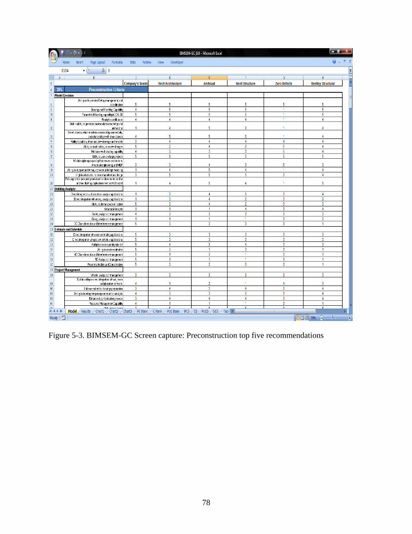
78
Figure 5-3. BIMSEM-GC Screen capture: Preconstruction top five recommendations
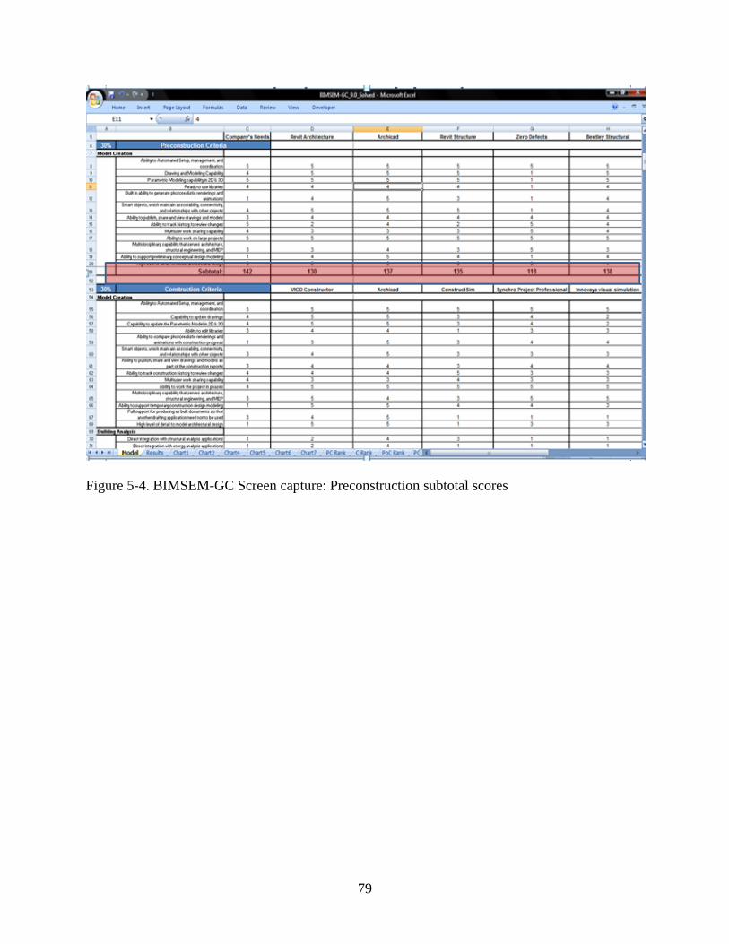
79
Figure 5-4. BIMSEM-GC Screen capture: Preconstruction subtotal scores
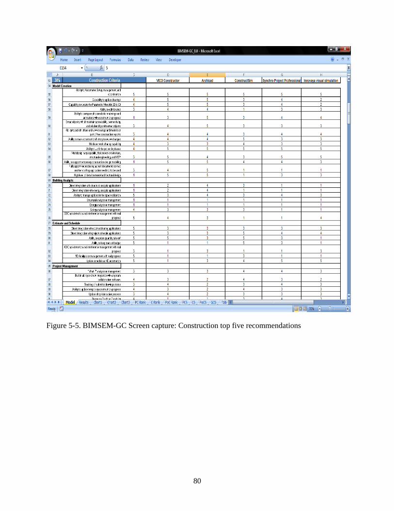
80
Figure 5-5. BIMSEM-GC Screen capture: Construction top five recommendations
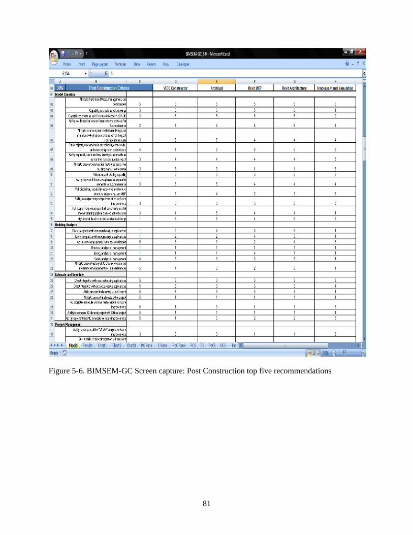
81
Figure 5-6. BIMSEM-GC Screen capture: Post Construction top five recommendations
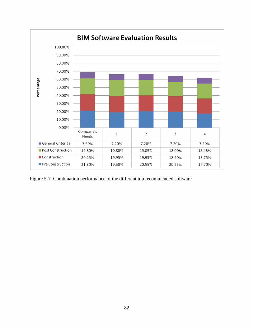
82
Figure 5-7. Combination performance of the different top recommended software
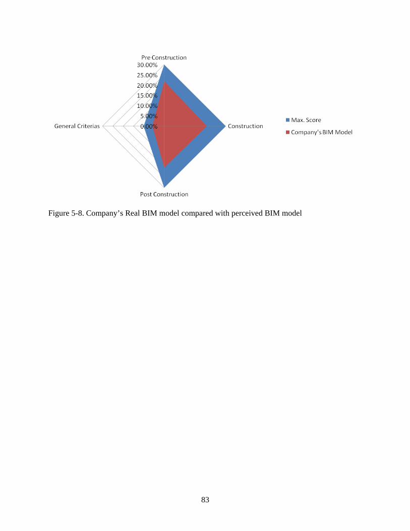
83
Figure 5-8. Company’s Real BIM model compared with perceived BIM model
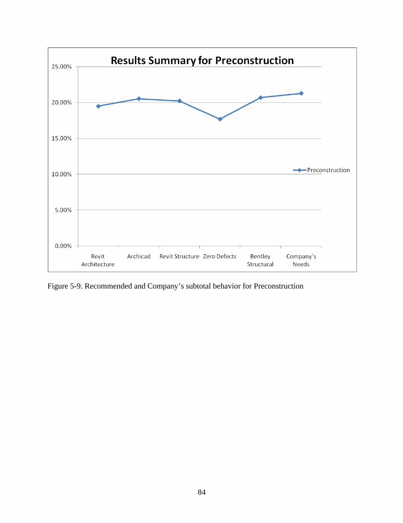
84
Figure 5-9. Recommended and Company’s subtotal behavior for Preconstruction
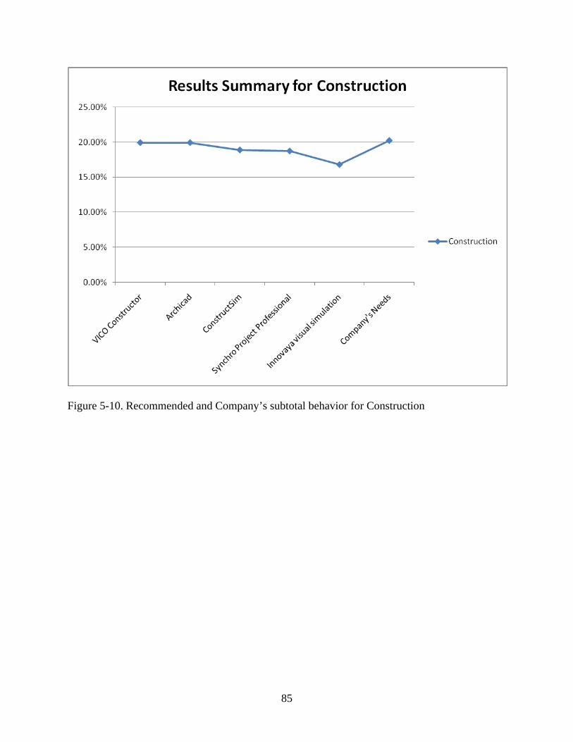
85
Figure 5-10. Recommended and Company’s subtotal behavior for Construction
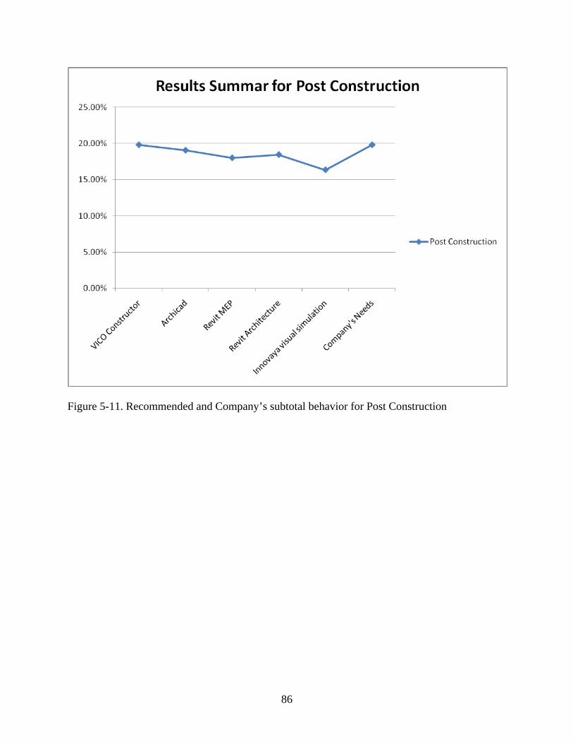
86
Figure 5-11. Recommended and Company’s subtotal behavior for Post Construction
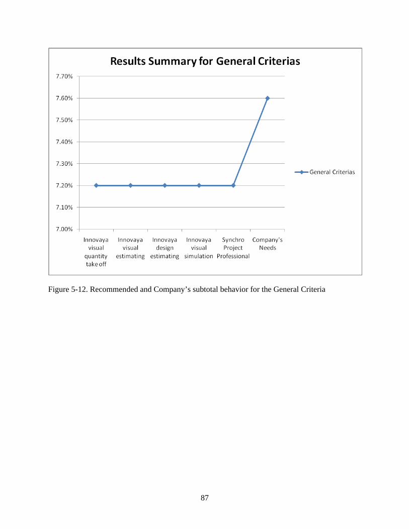
87
Figure 5-12. Recommended and Company’s subtotal behavior for the General Criteria

88
CHAPTER 6 CONCLUSIONS AND RECOMMENDATIONS
Building Information Modeling technology is being used more and more by general
contractors, the need to optimize processes, cost, quality, and safety in the industry creates the
perfect conditions to guarantee that BIM is going to be around from this point on. BIM
technology will continue to evolve offering unthinkable solutions nowadays for the construction
industry and bringing more applications to a market that today seems to be full of applications.
This study looked at 33 different software packages ranking them by the authors’ criteria and
acquired knowledge during the preparation of the study, creating the baseline for an interactive
evaluation model. The proposed model should be continuously updated and fed constantly with
other BIM Packages and new solutions from companies, perhaps incorporating more evaluation
criteria or changing some of them according to their needs.
The model created during this study looked at the company’s needs to recommend the
five software packages that come closest to satisfying those needs. The model will not
recommend the best software in the market, but the software packages that fit the best the
company’s needs. It is recommended for future models to consider suggesting not only the
software that comes closest to meeting the GC needs but also those that exceed them in order to
allow the company to consider any future grow.
From the initial evaluation of the 33 software packages it was noticed that the average
performance was not as good as expected when looking at the individual solution, but is can be
expected that the performance will be improved when using a suit of solutions for certain project.
Also from the evaluation of the 33 software solutions looked at in this research, one
conclusion was that there is no individual package that satisfies all the possible company’s needs
looked at as part of this study. The sum or the combination of different packages for different

89
phases of the project would be the best option for a company looking to implement BIM
technology during all the construction process.
The proposed use of different software packages for every phase of construction
highlights the importance of interoperable programs, where no matter what software is being
used during the project, the product of that particular software will be recognize entirely by the
rest of the software packages. An analysis of the integration of different software packages would
be recommended to determine which combination fulfills the most company’s needs when
applied to the different phases of the project for a general contractor.
Looking at the study of the individual solutions, a set of common applications were
found. Applications like parametric modeling, quantity take off, clash detections, 4D simulations
and interoperable application can be consider the minimum standard for a BIM implementation
from a general contractor. Considering the great number of software developers that offer this in
one or all of their software packages.
Also a number of more specific applications were identified; applications that in most of
the cases applied more for the general contractor needs, but are still in the development phase
and which are not standard in every software package. These solutions were: 5D analyses, bill-of
materials, earned value analysis, collaboration tools, bidirectional links with fabrication
equipment, micromanagement capabilities, resource management, Monte Carlo risk analysis,
code compliance, etc.
It is important to remember that this study should be used as a complement to a structured
implementation process from the general contractor. Once the model is used and the preferred
software is selected, a trial period of the preferred software should be implemented to optimize
the benefits at the time of the full implementation.

90
CHAPTER 7 FUTURE DIRECTION
Building Information Modeling (BIM) is going to continue evolving and new software
packages will appear with more solutions for contractors. These new software packages will add
to the already great number of choices that general contractors already have increasing the
importance of having a software evaluation model tool, but not only that, it will also require a
tool that monitors how well the implemented software is being used.
The following section was divided in 2 parts, the first one discusses the evolution that the
BIM software packages may have and new opportunities on the horizon and the second part
discusses the necessary improvements to software evaluation techniques.
BIM software developers are going to start selling integrated solution considering that the
performance of every individual package is limited. Nowadays the industry is looking for more
integration of processes forcing the software developers to evolve and offer packages with a
group of solutions that satisfy more areas of the entire project than a solution that will only fulfill
the needs of one area.
Another application that the software developers may put to work in their packages is the
ability to check required codes. These codes can go from building codes, environmental codes,
structural codes, or a set of best design criteria, so far only Solibri Model Checker offers a
limited capacity to develop code checking, but is it is an application that the market will start
asking more and more for.
Laser scanning is an application that none of the studied software offered, but it may
bring big advantages to the contractor to be able to maintain a laser scan working during the
construction process to be able to track the process in real time and to automatically update the
model.

91
It is important to analyze the legal procedure once the selection decision is done; there
are some baselines for the legal requirements to look at when buying BIM software, specifically
requirements for the software vendors. These requirements can go from minimum performance
standards to maintenance and technical support expectations.
Another area where software evaluation needs to pay more attention is in keeping a
performance score of the software analyzed to monitor whether the selected software was the
best decision and to allow the user to understand much better their real needs.
92
APPENDIX PROGRAMMING OF THE BIM SOFTWARE EVALUATION MODEL FOR GENERAL
CONTRACTORS IN MS VISUAL BASIC
Sub Delete() ' ' Delete Macro ' Range("D5:H521").Select Selection.ClearContents Selection.Borders(xlDiagonalDown).LineStyle = xlNone Selection.Borders(xlDiagonalUp).LineStyle = xlNone Selection.Borders(xlEdgeLeft).LineStyle = xlNone Selection.Borders(xlEdgeTop).LineStyle = xlNone Selection.Borders(xlEdgeBottom).LineStyle = xlNone Selection.Borders(xlEdgeRight).LineStyle = xlNone Selection.Borders(xlInsideVertical).LineStyle = xlNone Selection.Borders(xlInsideHorizontal).LineStyle = xlNone Range("A5:C158").Select Range("C5").Activate Selection.Borders(xlDiagonalDown).LineStyle = xlNone Selection.Borders(xlDiagonalUp).LineStyle = xlNone With Selection.Borders(xlEdgeLeft) .LineStyle = xlContinuous .ColorIndex = 0 .TintAndShade = 0 .Weight = xlMedium End With With Selection.Borders(xlEdgeTop) .LineStyle = xlContinuous .ColorIndex = 0 .TintAndShade = 0 .Weight = xlMedium End With With Selection.Borders(xlEdgeBottom) .LineStyle = xlContinuous .ColorIndex = 0 .TintAndShade = 0 .Weight = xlMedium End With With Selection.Borders(xlEdgeRight) .LineStyle = xlContinuous .ColorIndex = 0 .TintAndShade = 0 .Weight = xlMedium End With Range("C8:C50").Select

93
Selection.ClearContents ActiveWindow.SmallScroll Down:=45 Range("C55:C97").Select Selection.ClearContents ActiveWindow.SmallScroll Down:=48 Range("C102:C144").Select Selection.ClearContents ActiveWindow.SmallScroll Down:=54 Range("C148:C157").Select Selection.ClearContents Range("D153").Select ActiveWindow.SmallScroll Down:=-183 Sheets("PCS").Select Range("A3:D35").Select ActiveWindow.SmallScroll Down:=-60 Range("B3:B36").Select Range("B36").Activate ActiveWindow.SmallScroll Down:=18 Range("C27").Select ActiveWindow.SmallScroll Down:=-81 Range("A3").Select ActiveCell.FormulaR1C1 = "Rank " With ActiveCell.Characters(Start:=1, Length:=6).Font .Name = "Arial" .FontStyle = "Regular" .Size = 10 .Strikethrough = False .Superscript = False .Subscript = False .OutlineFont = False .Shadow = False .Underline = xlUnderlineStyleNone .ColorIndex = xlAutomatic .TintAndShade = 0 .ThemeFont = xlThemeFontNone End With Range("B3").Select ActiveCell.FormulaR1C1 = "Software" With ActiveCell.Characters(Start:=1, Length:=8).Font .Name = "Arial" .FontStyle = "Regular" .Size = 10 .Strikethrough = False .Superscript = False .Subscript = False .OutlineFont = False

94
.Shadow = False .Underline = xlUnderlineStyleNone .ColorIndex = xlAutomatic .TintAndShade = 0 .ThemeFont = xlThemeFontNone End With Range("C3").Select ActiveCell.FormulaR1C1 = "Company Score" With ActiveCell.Characters(Start:=1, Length:=13).Font .Name = "Arial" .FontStyle = "Regular" .Size = 10 .Strikethrough = False .Superscript = False .Subscript = False .OutlineFont = False .Shadow = False .Underline = xlUnderlineStyleNone .ColorIndex = xlAutomatic .TintAndShade = 0 .ThemeFont = xlThemeFontNone End With Range("D3").Select ActiveCell.FormulaR1C1 = "Software Score" With ActiveCell.Characters(Start:=1, Length:=14).Font .Name = "Arial" .FontStyle = "Regular" .Size = 10 .Strikethrough = False .Superscript = False .Subscript = False .OutlineFont = False .Shadow = False .Underline = xlUnderlineStyleNone .ColorIndex = xlAutomatic .TintAndShade = 0 .ThemeFont = xlThemeFontNone End With Range("E3").Select ActiveCell.FormulaR1C1 = "Dif." With ActiveCell.Characters(Start:=1, Length:=4).Font .Name = "Arial" .FontStyle = "Regular" .Size = 10 .Strikethrough = False .Superscript = False

95
.Subscript = False .OutlineFont = False .Shadow = False .Underline = xlUnderlineStyleNone .ColorIndex = xlAutomatic .TintAndShade = 0 .ThemeFont = xlThemeFontNone End With Range("F3").Select ActiveCell.FormulaR1C1 = "Abs" With ActiveCell.Characters(Start:=1, Length:=3).Font .Name = "Arial" .FontStyle = "Regular" .Size = 10 .Strikethrough = False .Superscript = False .Subscript = False .OutlineFont = False .Shadow = False .Underline = xlUnderlineStyleNone .ColorIndex = xlAutomatic .TintAndShade = 0 .ThemeFont = xlThemeFontNone End With Range("G3").Select ActiveCell.FormulaR1C1 = "Comp. C.V 95%" With ActiveCell.Characters(Start:=1, Length:=13).Font .Name = "Arial" .FontStyle = "Regular" .Size = 10 .Strikethrough = False .Superscript = False .Subscript = False .OutlineFont = False .Shadow = False .Underline = xlUnderlineStyleNone .ColorIndex = xlAutomatic .TintAndShade = 0 .ThemeFont = xlThemeFontNone End With Range("H3").Select ActiveCell.FormulaR1C1 = "Soft. C.V 95%" With ActiveCell.Characters(Start:=1, Length:=13).Font .Name = "Arial" .FontStyle = "Regular" .Size = 10
96
.Strikethrough = False .Superscript = False .Subscript = False .OutlineFont = False .Shadow = False .Underline = xlUnderlineStyleNone .ColorIndex = xlAutomatic .TintAndShade = 0 .ThemeFont = xlThemeFontNone End With Range("I3").Select ActiveCell.FormulaR1C1 = "Dif." With ActiveCell.Characters(Start:=1, Length:=4).Font .Name = "Arial" .FontStyle = "Regular" .Size = 10 .Strikethrough = False .Superscript = False .Subscript = False .OutlineFont = False .Shadow = False .Underline = xlUnderlineStyleNone .ColorIndex = xlAutomatic .TintAndShade = 0 .ThemeFont = xlThemeFontNone End With Range("J3").Select ActiveCell.FormulaR1C1 = "Abs" With ActiveCell.Characters(Start:=1, Length:=3).Font .Name = "Arial" .FontStyle = "Regular" .Size = 10 .Strikethrough = False .Superscript = False .Subscript = False .OutlineFont = False .Shadow = False .Underline = xlUnderlineStyleNone .ColorIndex = xlAutomatic .TintAndShade = 0 .ThemeFont = xlThemeFontNone End With Range("A4:D36").Select Selection.ClearContents Range("E4:F4").Select Selection.Copy

97
Range("E5:F36").Select ActiveSheet.Paste Application.CutCopyMode = False Range("G4:H36").Select Selection.ClearContents Range("I4:J4").Select Selection.Copy Range("I5:J36").Select ActiveSheet.Paste Application.CutCopyMode = False Range("A3:J36").Select Range("J36").Activate Selection.Copy Sheets("CS").Select Range("A3").Select ActiveSheet.Paste ActiveWindow.SmallScroll Down:=-48 Sheets("PoCS").Select Range("A3").Select ActiveSheet.Paste Sheets("GCS").Select Range("A3").Select ActiveSheet.Paste Range("E14:J36").Select Application.CutCopyMode = False Range("A1").Select Sheets("Model").Select End Sub Sub Recommend() ' ' Recommend Macro ' ' Sheets("Rank").Select ActiveWindow.SmallScroll Down:=-879 Range("C4:AI4").Select Selection.Copy Sheets("PCS").Select Range("B4").Select Selection.PasteSpecial Paste:=xlPasteValues, Operation:=xlNone, SkipBlanks _ :=False, Transpose:=True ActiveWindow.SmallScroll Down:=-6 Sheets("CS").Select Range("B4").Select Selection.PasteSpecial Paste:=xlPasteValues, Operation:=xlNone, SkipBlanks _
98
:=False, Transpose:=True Sheets("PoCS").Select Range("B4").Select Selection.PasteSpecial Paste:=xlPasteValues, Operation:=xlNone, SkipBlanks _ :=False, Transpose:=True Sheets("GCS").Select Range("B4").Select Selection.PasteSpecial Paste:=xlPasteValues, Operation:=xlNone, SkipBlanks _ :=False, Transpose:=True Sheets("Rank").Select ActiveWindow.SmallScroll ToRight:=-20 ActiveWindow.LargeScroll ToRight:=-3 ActiveWindow.SmallScroll ToRight:=-2 ActiveWindow.SmallScroll Down:=36 Range("C50:AI50").Select Application.CutCopyMode = False Selection.Copy Sheets("PCS").Select Range("D4").Select Selection.PasteSpecial Paste:=xlPasteValues, Operation:=xlNone, SkipBlanks _ :=False, Transpose:=True ActiveWindow.SmallScroll Down:=-15 Sheets("Rank").Select ActiveWindow.SmallScroll ToRight:=-30 ActiveWindow.SmallScroll Down:=48 Range("C97:AI97").Select Application.CutCopyMode = False Selection.Copy Sheets("CS").Select Range("D4").Select Selection.PasteSpecial Paste:=xlPasteValues, Operation:=xlNone, SkipBlanks _ :=False, Transpose:=True ActiveWindow.SmallScroll Down:=-54 Sheets("Rank").Select ActiveWindow.SmallScroll ToRight:=-30 ActiveWindow.SmallScroll Down:=51 Range("C144:AI144").Select Application.CutCopyMode = False Selection.Copy Sheets("PoCS").Select Range("D4").Select Selection.PasteSpecial Paste:=xlPasteValues, Operation:=xlNone, SkipBlanks _ :=False, Transpose:=True Sheets("Rank").Select ActiveWindow.SmallScroll ToRight:=-29 ActiveWindow.SmallScroll Down:=9
99
Range("C157:AI157").Select Application.CutCopyMode = False Selection.Copy Sheets("GCS").Select Range("D4").Select Selection.PasteSpecial Paste:=xlPasteValues, Operation:=xlNone, SkipBlanks _ :=False, Transpose:=True ActiveWindow.SmallScroll Down:=-33 Sheets("Rank").Select ActiveWindow.SmallScroll Down:=-3 ActiveWindow.SmallScroll ToRight:=-30 ActiveWindow.SmallScroll Down:=9 Range("C169:AI169").Select Application.CutCopyMode = False Selection.Copy Sheets("PCS").Select Range("H4").Select Selection.PasteSpecial Paste:=xlPasteValues, Operation:=xlNone, SkipBlanks _ :=False, Transpose:=True ActiveWindow.SmallScroll Down:=-6 Sheets("Rank").Select ActiveWindow.SmallScroll ToRight:=-2 ActiveWindow.SmallScroll Down:=-3 ActiveWindow.SmallScroll ToRight:=-28 ActiveWindow.SmallScroll Down:=12 Range("C180:AI180").Select Application.CutCopyMode = False Selection.Copy Sheets("CS").Select Range("H4").Select Selection.PasteSpecial Paste:=xlPasteValues, Operation:=xlNone, SkipBlanks _ :=False, Transpose:=True Sheets("Rank").Select ActiveWindow.SmallScroll ToRight:=-29 ActiveWindow.SmallScroll Down:=12 Range("C191:AI191").Select Application.CutCopyMode = False Selection.Copy Sheets("PoCS").Select Range("H4").Select Selection.PasteSpecial Paste:=xlPasteValues, Operation:=xlNone, SkipBlanks _ :=False, Transpose:=True Sheets("Rank").Select ActiveWindow.SmallScroll ToRight:=-29 ActiveWindow.SmallScroll Down:=6 Range("C202:AI202").Select
100
Application.CutCopyMode = False Selection.Copy Sheets("GCS").Select Range("H4").Select Selection.PasteSpecial Paste:=xlPasteValues, Operation:=xlNone, SkipBlanks _ :=False, Transpose:=True ActiveWindow.SmallScroll Down:=-15 Sheets("PCS").Select Range("C4").Select Sheets("Model").Select ActiveWindow.SmallScroll Down:=30 Range("C51").Select Application.CutCopyMode = False Selection.Copy Sheets("PCS").Select Range("C4").Select Selection.PasteSpecial Paste:=xlPasteValues, Operation:=xlNone, SkipBlanks _ :=False, Transpose:=False Application.CutCopyMode = False Selection.Copy Range("C5:C36").Select Selection.PasteSpecial Paste:=xlPasteValues, Operation:=xlNone, SkipBlanks _ :=False, Transpose:=False Sheets("Model").Select ActiveWindow.SmallScroll Down:=51 Range("C98").Select Application.CutCopyMode = False Selection.Copy Sheets("CS").Select Range("C4").Select Selection.PasteSpecial Paste:=xlPasteValues, Operation:=xlNone, SkipBlanks _ :=False, Transpose:=False Application.CutCopyMode = False Selection.Copy Range("C5:C36").Select Selection.PasteSpecial Paste:=xlPasteValues, Operation:=xlNone, SkipBlanks _ :=False, Transpose:=False Sheets("Model").Select ActiveWindow.SmallScroll Down:=57 Range("C145").Select Application.CutCopyMode = False Selection.Copy Sheets("PoCS").Select Range("C4").Select Selection.PasteSpecial Paste:=xlPasteValues, Operation:=xlNone, SkipBlanks _ :=False, Transpose:=True

101
Application.CutCopyMode = False Selection.Copy Range("C5:C36").Select Selection.PasteSpecial Paste:=xlPasteValues, Operation:=xlNone, SkipBlanks _ :=False, Transpose:=False Sheets("Model").Select ActiveWindow.SmallScroll Down:=12 Range("C158").Select Application.CutCopyMode = False Selection.Copy Sheets("GCS").Select Range("C4").Select Selection.PasteSpecial Paste:=xlPasteValues, Operation:=xlNone, SkipBlanks _ :=False, Transpose:=False Application.CutCopyMode = False Selection.Copy Range("C5:C36").Select Selection.PasteSpecial Paste:=xlPasteValues, Operation:=xlNone, SkipBlanks _ :=False, Transpose:=False Sheets("Model").Select Range("C170").Select Application.CutCopyMode = False Selection.Copy Sheets("PCS").Select Range("G4").Select Selection.PasteSpecial Paste:=xlPasteValues, Operation:=xlNone, SkipBlanks _ :=False, Transpose:=False Application.CutCopyMode = False Selection.Copy Range("G5:G36").Select Selection.PasteSpecial Paste:=xlPasteValues, Operation:=xlNone, SkipBlanks _ :=False, Transpose:=False Sheets("Model").Select ActiveWindow.SmallScroll Down:=12 Range("C181").Select Application.CutCopyMode = False Selection.Copy Sheets("CS").Select Range("G4").Select Selection.PasteSpecial Paste:=xlPasteValues, Operation:=xlNone, SkipBlanks _ :=False, Transpose:=False Application.CutCopyMode = False Selection.Copy Range("G5:G36").Select Selection.PasteSpecial Paste:=xlPasteValues, Operation:=xlNone, SkipBlanks _ :=False, Transpose:=False
102
Sheets("Model").Select ActiveWindow.SmallScroll Down:=15 Range("C192").Select Application.CutCopyMode = False Selection.Copy Sheets("PoCS").Select Range("G4").Select Selection.PasteSpecial Paste:=xlPasteValues, Operation:=xlNone, SkipBlanks _ :=False, Transpose:=False Application.CutCopyMode = False Selection.Copy Range("G5:G36").Select Selection.PasteSpecial Paste:=xlPasteValues, Operation:=xlNone, SkipBlanks _ :=False, Transpose:=False Sheets("Model").Select ActiveWindow.SmallScroll Down:=9 Range("C203").Select Application.CutCopyMode = False Selection.Copy Sheets("GCS").Select Range("G4").Select Selection.PasteSpecial Paste:=xlPasteValues, Operation:=xlNone, SkipBlanks _ :=False, Transpose:=False Application.CutCopyMode = False Selection.Copy Range("G5:G36").Select Selection.PasteSpecial Paste:=xlPasteValues, Operation:=xlNone, SkipBlanks _ :=False, Transpose:=False Sheets("PCS").Select Range("A5").Select Application.CutCopyMode = False ActiveWorkbook.Worksheets("PCS").Sort.SortFields.Clear ActiveWorkbook.Worksheets("PCS").Sort.SortFields.Add Key:=Range("F3:F36"), _ SortOn:=xlSortOnValues, Order:=xlAscending, DataOption:=xlSortNormal With ActiveWorkbook.Worksheets("PCS").Sort .SetRange Range("A2:J36") .Header = xlYes .MatchCase = False .Orientation = xlTopToBottom .SortMethod = xlPinYin .Apply End With ActiveWorkbook.Worksheets("PCS").Sort.SortFields.Clear ActiveWorkbook.Worksheets("PCS").Sort.SortFields.Add Key:=Range("J3:J36"), _ SortOn:=xlSortOnValues, Order:=xlAscending, DataOption:=xlSortNormal With ActiveWorkbook.Worksheets("PCS").Sort
103
.SetRange Range("A2:J36") .Header = xlYes .MatchCase = False .Orientation = xlTopToBottom .SortMethod = xlPinYin .Apply End With ActiveWindow.SmallScroll Down:=-21 Range("A3").Select ActiveCell.FormulaR1C1 = "1" Range("A4").Select ActiveCell.FormulaR1C1 = "2" Range("A5").Select ActiveCell.FormulaR1C1 = "3" Range("A6").Select ActiveCell.FormulaR1C1 = "4" Range("A7").Select ActiveCell.FormulaR1C1 = "5" Range("B4:B8").Select Selection.Copy Sheets("Model").Select ActiveWindow.SmallScroll Down:=-372 Range("D5").Select Selection.PasteSpecial Paste:=xlPasteValues, Operation:=xlNone, SkipBlanks _ :=False, Transpose:=True Columns("D:D").EntireColumn.AutoFit Columns("E:E").EntireColumn.AutoFit Columns("F:F").EntireColumn.AutoFit ActiveWindow.SmallScroll ToRight:=2 Columns("G:G").EntireColumn.AutoFit Columns("H:H").EntireColumn.AutoFit ActiveWindow.SmallScroll ToRight:=-2 Range("C7:C51").Select Application.CutCopyMode = False Selection.Copy ActiveWindow.SmallScroll Down:=-42 Range("D7:H51").Select Selection.PasteSpecial Paste:=xlPasteFormats, Operation:=xlNone, _ SkipBlanks:=False, Transpose:=False Application.CutCopyMode = False Range("C5").Select Selection.Copy Range("D5:H5").Select Selection.PasteSpecial Paste:=xlPasteFormats, Operation:=xlNone, _ SkipBlanks:=False, Transpose:=False Application.CutCopyMode = False
104
Columns("D:D").EntireColumn.AutoFit Columns("E:E").EntireColumn.AutoFit Columns("F:F").ColumnWidth = 9.29 Columns("F:F").EntireColumn.AutoFit Columns("G:G").EntireColumn.AutoFit ActiveWindow.SmallScroll ToRight:=2 Columns("H:H").EntireColumn.AutoFit ActiveWindow.SmallScroll Down:=-3 ActiveWindow.SmallScroll ToRight:=-2 Sheets("CS").Select Range("B4").Select ActiveWorkbook.Worksheets("CS").Sort.SortFields.Clear ActiveWorkbook.Worksheets("CS").Sort.SortFields.Add Key:=Range("F3:F36"), _ SortOn:=xlSortOnValues, Order:=xlAscending, DataOption:=xlSortNormal With ActiveWorkbook.Worksheets("CS").Sort .SetRange Range("A2:J36") .Header = xlYes .MatchCase = False .Orientation = xlTopToBottom .SortMethod = xlPinYin .Apply End With ActiveWorkbook.Worksheets("CS").Sort.SortFields.Clear ActiveWorkbook.Worksheets("CS").Sort.SortFields.Add Key:=Range("J3:J36"), _ SortOn:=xlSortOnValues, Order:=xlAscending, DataOption:=xlSortNormal With ActiveWorkbook.Worksheets("CS").Sort .SetRange Range("A2:J36") .Header = xlYes .MatchCase = False .Orientation = xlTopToBottom .SortMethod = xlPinYin .Apply End With Range("A3").Select ActiveCell.FormulaR1C1 = "1" Range("A4").Select ActiveCell.FormulaR1C1 = "2" Range("A5").Select ActiveCell.FormulaR1C1 = "3" Range("A6").Select ActiveCell.FormulaR1C1 = "4" Range("A7").Select ActiveCell.FormulaR1C1 = "5" Range("B4:B8").Select Selection.Copy Sheets("Model").Select

105
ActiveWindow.SmallScroll Down:=45 Range("D53").Select Selection.PasteSpecial Paste:=xlPasteValues, Operation:=xlNone, SkipBlanks _ :=False, Transpose:=True Range("D5:H51").Select Range("D51").Activate Application.CutCopyMode = False Selection.Copy ActiveWindow.SmallScroll ToRight:=-3 ActiveWindow.SmallScroll Down:=42 Range("D53:H98").Select Selection.PasteSpecial Paste:=xlPasteFormats, Operation:=xlNone, _ SkipBlanks:=False, Transpose:=False Application.CutCopyMode = False ActiveWindow.SmallScroll Down:=48 Sheets("PoCS").Select Range("F4").Select ActiveWorkbook.Worksheets("PoCS").Sort.SortFields.Clear ActiveWorkbook.Worksheets("PoCS").Sort.SortFields.Add Key:=Range("F3:F36"), _ SortOn:=xlSortOnValues, Order:=xlAscending, DataOption:=xlSortNormal With ActiveWorkbook.Worksheets("PoCS").Sort .SetRange Range("A2:J36") .Header = xlYes .MatchCase = False .Orientation = xlTopToBottom .SortMethod = xlPinYin .Apply End With ActiveWorkbook.Worksheets("PoCS").Sort.SortFields.Clear ActiveWorkbook.Worksheets("PoCS").Sort.SortFields.Add Key:=Range("J3:J36"), _ SortOn:=xlSortOnValues, Order:=xlAscending, DataOption:=xlSortNormal With ActiveWorkbook.Worksheets("PoCS").Sort .SetRange Range("A2:J36") .Header = xlYes .MatchCase = False .Orientation = xlTopToBottom .SortMethod = xlPinYin .Apply End With ActiveWindow.SmallScroll Down:=-42 Range("A3").Select ActiveCell.FormulaR1C1 = "1" Range("A4").Select ActiveCell.FormulaR1C1 = "2" Range("A5").Select ActiveCell.FormulaR1C1 = "3"
106
Range("A6").Select ActiveCell.FormulaR1C1 = "4" Range("A7").Select ActiveCell.FormulaR1C1 = "5" Range("B4:B8").Select Selection.Copy Sheets("Model").Select ActiveWindow.SmallScroll Down:=-3 ActiveWindow.SmallScroll ToRight:=-2 Range("D98:H98").Select Application.CutCopyMode = False Selection.Borders(xlDiagonalDown).LineStyle = xlNone Selection.Borders(xlDiagonalUp).LineStyle = xlNone With Selection.Borders(xlEdgeLeft) .LineStyle = xlContinuous .ColorIndex = 0 .TintAndShade = 0 .Weight = xlMedium End With With Selection.Borders(xlEdgeTop) .LineStyle = xlContinuous .ColorIndex = 0 .TintAndShade = 0 .Weight = xlMedium End With With Selection.Borders(xlEdgeBottom) .LineStyle = xlContinuous .ColorIndex = 0 .TintAndShade = 0 .Weight = xlMedium End With With Selection.Borders(xlEdgeRight) .LineStyle = xlContinuous .ColorIndex = 0 .TintAndShade = 0 .Weight = xlMedium End With Selection.Borders(xlInsideHorizontal).LineStyle = xlNone ActiveWindow.SmallScroll ToRight:=-2 Range("D100").Select Sheets("PoCS").Select Selection.Copy Sheets("Model").Select Selection.PasteSpecial Paste:=xlPasteValues, Operation:=xlNone, SkipBlanks _ :=False, Transpose:=True ActiveWindow.SmallScroll Down:=-39
107
Range("D53:H98").Select Application.CutCopyMode = False Selection.Copy ActiveWindow.SmallScroll Down:=15 Range("D100:H145").Select Selection.PasteSpecial Paste:=xlPasteFormats, Operation:=xlNone, _ SkipBlanks:=False, Transpose:=False Application.CutCopyMode = False ActiveWindow.SmallScroll Down:=48 Range("H148").Select ActiveWindow.SmallScroll ToRight:=-2 Sheets("GCS").Select Range("D5").Select ActiveWorkbook.Worksheets("GCS").Sort.SortFields.Clear ActiveWorkbook.Worksheets("GCS").Sort.SortFields.Add Key:=Range("F3:F36"), _ SortOn:=xlSortOnValues, Order:=xlAscending, DataOption:=xlSortNormal With ActiveWorkbook.Worksheets("GCS").Sort .SetRange Range("A2:J36") .Header = xlYes .MatchCase = False .Orientation = xlTopToBottom .SortMethod = xlPinYin .Apply End With ActiveWorkbook.Worksheets("GCS").Sort.SortFields.Clear ActiveWorkbook.Worksheets("GCS").Sort.SortFields.Add Key:=Range("J3:J36"), _ SortOn:=xlSortOnValues, Order:=xlAscending, DataOption:=xlSortNormal With ActiveWorkbook.Worksheets("GCS").Sort .SetRange Range("A2:J36") .Header = xlYes .MatchCase = False .Orientation = xlTopToBottom .SortMethod = xlPinYin .Apply End With Range("A3").Select ActiveCell.FormulaR1C1 = "1" Range("A4").Select ActiveCell.FormulaR1C1 = "2" Range("A5").Select ActiveCell.FormulaR1C1 = "3" Range("A6").Select ActiveCell.FormulaR1C1 = "4" Range("A7").Select ActiveCell.FormulaR1C1 = "5" Range("B4:B8").Select
108
Selection.Copy Sheets("Model").Select Range("D147").Select Selection.PasteSpecial Paste:=xlPasteValues, Operation:=xlNone, SkipBlanks _ :=False, Transpose:=True ActiveWindow.SmallScroll Down:=-45 Range("D100:H100").Select Application.CutCopyMode = False Selection.Copy ActiveWindow.SmallScroll Down:=51 Range("D147:H147").Select Selection.PasteSpecial Paste:=xlPasteFormats, Operation:=xlNone, _ SkipBlanks:=False, Transpose:=False Application.CutCopyMode = False Range("C148:C158").Select Selection.Copy Range("D148:H158").Select Selection.PasteSpecial Paste:=xlPasteFormats, Operation:=xlNone, _ SkipBlanks:=False, Transpose:=False Application.CutCopyMode = False Range("E154").Select Columns("D:D").EntireColumn.AutoFit Columns("E:E").EntireColumn.AutoFit ActiveWindow.SmallScroll ToRight:=3 Columns("E:E").EntireColumn.AutoFit Columns("F:F").EntireColumn.AutoFit Columns("G:G").EntireColumn.AutoFit Columns("H:H").EntireColumn.AutoFit ActiveWindow.SmallScroll Down:=-336 ActiveWindow.SmallScroll ToRight:=-1 ActiveWindow.SmallScroll Down:=-3 ActiveWindow.SmallScroll ToRight:=-2 Sheets("Results").Select Range("C5").Select Sheets("Model").Select Dim i, j, n, c As Integer c = 3 j = 1 For n = 1 To 5 Do While j = 1 If Sheet4.Cells(5, n + 3) = Sheet3.Cells(4, c) Then For i = 7 To 51 Sheet4.Cells(i, n + 3) = Sheet3.Cells(i - 1, c) Next i j = 0 Else: c = c + 1
109
End If Loop j = 1 c = 3 Next n Dim o, p, q, r As Integer r = 3 p = 1 For q = 1 To 5 Do While p = 1 If Sheet4.Cells(53, q + 3) = Sheet3.Cells(4, r) Then For o = 54 To 98 Sheet4.Cells(o, q + 3) = Sheet3.Cells(o - 1, r) Next o p = 0 Else: r = r + 1 End If Loop p = 1 r = 3 Next q Dim s, t, u, v As Integer v = 3 t = 1 For u = 1 To 5 Do While t = 1 If Sheet4.Cells(100, u + 3) = Sheet3.Cells(4, v) Then For s = 101 To 145 Sheet4.Cells(s, u + 3) = Sheet3.Cells(s - 1, v) Next s t = 0 Else: v = v + 1 End If Loop t = 1 v = 3 Next u Dim w, x, y, z As Integer z = 3 x = 1 For y = 1 To 5 Do While x = 1 If Sheet4.Cells(147, y + 3) = Sheet3.Cells(4, z) Then For w = 148 To 158 Sheet4.Cells(w, y + 3) = Sheet3.Cells(w - 1, z) Next w

110
x = 0 Else: z = z + 1 End If Loop x = 1 z = 3 Next y End Sub
111
LIST OF REFERENCES
Autodesk, Inc. Site. 2009. Autodesk- Autodesk Navisworks- Features. Jan 28, 2009. <http://usa.autodesk.com/adsk/servlet/index?siteID=123112&id=10726113 >.
Autodesk, Inc. Site. 2009. Autodesk- Design Review-Detailed Features. Jan 28, 2009. <http://usa.autodesk.com/adsk/servlet/index?siteID=123112&id=4086277 >.
Autodesk, Inc. Site. 2009. Autodesk- Revit Architecture- Features. Jan 28, 2009. <http://usa.autodesk.com/adsk/servlet/index?siteID=123112&id=8479974 >.
Autodesk, Inc. Site. 2009. Autodesk- Revit MEP- Features. Jan 28, 2009. <http://usa.autodesk.com/adsk/servlet/index?siteID=123112&id=8529989 >.
Autodesk, Inc. Site. 2009. Autodesk- Revit Structure- Features. Jan 28, 2009. <http://usa.autodesk.com/adsk/servlet/index?siteID=123112&id=8447072 >.
Autodesk, Inc. Site. 2009. Autodesk-Autodesk 3ds Max Design-Detailed Features. Jan 28, 2009. <http://usa.autodesk.com/adsk/servlet/index?siteID=123112&id=10370942 >.
Bentley Systems, Incorporated Site. 2008. CP: ConstructSim. Jan 28, 2009. <http://www.commonpointinc.com/products/constructsim/constructsim-pipe.asp>.
Bentley Systems, Incorporated Site. 2009. BBES Features list. Jan 28, 2009 <http://bentley.com/en-US/Products/Bentley+Building+Electrical+Systems/Features-list.htm>.
Bentley Systems, Incorporated Site. 2009. Bentley Architecture Features. Jan 28, 2009. <http://bentley.com/en-US/Products/Bentley+Architecture/Features-list.htm>.
Bentley Systems, Incorporated Site. 2009. Bentley Project Wise Project Team Collaboration Software Products. Jan 28, 2009. <http://bentley.com/en-US/Products/ProjectWise+Project+Team+Collaboration/Features-list.htm>.
Bentley Systems, Incorporated Site. 2009. Bentley Structural Features list. Jan 28, 2009. <http://bentley.com/en-US/Products/Bentley+Structural/Features-list.htm>.
Bentley Systems, Incorporated Site. 2009. Features list for Bentley Building Mechanical Systems. Jan 28, 2009. <http://bentley.com/en-US/Products/Bentley+Building+Mechanical+Systems/Features-list.htm>.
Crney, D., and Wallnau, K. (1998). “A basis for evaluation of commercial software.” Information and Software Technology, 40 (1998), 851-860
Eastman, C. M. (2008). BIM handbook: A guide to building information modeling for owners, managers, designers, engineers, and contractors, Wiley, Hoboken, N.J.
112
Ernstrom, J.W. (2006). The contractors' guide to BIM, Associated General Contractors of America, Arlington, Virginia.
Gehry Technologies. 2009. Gehry Technologies-Digital Project™Products. Jan 28, 2009. <http://www.gehrytechnologies.com/index.php?option=com_content&task=view&id=97&Itemid=211 >.
Goldberg, Edward H. (2004). “The Building Information Model.” CADalyst, 21(11), 56.
Graphisoft R&D Zrt. 2009. Freedom to Design-ArchiCAD Supports Your Style. Jan 28, 2009. <http://www.graphisoft.com/products/virtual_bilding/optimized_for_design/?printable=1zerodefects.htm >.
Innovaya, LLC. Site. 2008. Innovaya Visual BIM. Jan 28, 2009. <http://www.innovaya.com/prod_vb.htm >.
Innovaya, LLC. Site. 2008. Innovaya Visual Estimating. Jan 28, 2009. <http://www.innovaya.com/prod_de.htm >.
Innovaya, LLC. Site. 2008. Innovaya Visual Estimating. Jan 28, 2009. <http://www.innovaya.com/prod_ve.htm >.
Innovaya, LLC. Site. 2008. Innovaya Visual Quantification. Jan 28, 2009. <http://www.innovaya.com/prod_vq.htm >.
Innovaya, LLC. Site. 2008. Innovaya Visual Quantification. Jan 28, 2009. <http://www.innovaya.com/prod_vs.htm >.
Jadhav, A., and Sonar, R. (2009). “Evaluating and Selecting Software Packages: A Review.” Information and Software Technology, 51 (2009), 555-563.
Kennett, E. 2005. Charter for the National Building Information Model (BIM) Standard. NIBS-FIC website.<http://www.facilityinformationcouncil.org/bim/pdfs/NBIMS_Charter.pdf>. (October 1, 2007).
Khemlani, Lachmi. 2007. Top Criteria for BIM Solutions: AECbytes Survey Results. Jan 12, 2009. <http://www.aecbytes.com/feature/2007/BIMSurveyReport.html>.
Kunz, J., and Gilligan, B. (2007). “Value from VDC/BIM Use: Survey Results-November 2007.” CIFE/CURT/GSA
Nemetscheck Vectorworks. (2008) “Vectorworks Architect 2009-Features List” Nemetcheck North America, Inc.
ONUMA Site. 2008. Introduction to OPS. Jan 28, 2009. <http://onuma.com/video.php?v=IntroToOPSsmB>.

113
Project Blue Print Site. 2005-2010. Project Blue Print-Zero Defects. Jan 28, 2009. <http://www.projectblueprint.com/zerodefects.htm >.
Roman, S. (1999). Writing Excel Macros, 1st Edition., O’Reilly, California
SmartTech Site. 2008. BIM Past, BIM Future. Feb 18, 2009. <http://smartech.gatech.edu/handle/1853/22439>.
Solibri, Inc. Site. 2009. Business Benefits-Solibri. Jan 28, 2009. <http://www.solibri.com/solibri-model-checker/business-benefits.html>.
Solibri, Inc. Site. 2009. Functionality Highlights-Solibri. Jan 28, 2009. <http://www.solibri.com-model-checker/functionality-highlights.html>.
Solibri, Inc. Site. 2009. IFC Support –Solibri. Jan 28, 2009. <http://www.solibri.com-model-checker/ifc-support.html>.
Solibri, Inc. Site. 2009. Overview-Solibri. Jan 28, 2009. <http://www.solibri.com-model-checker.html>.
Solibri, Inc. Site. 2009. Solibri Issue Locator –Solibri. Jan 28, 2009. <http://www.solibri.com/solibri-issue-locator.html>.
Solibri, Inc. Site. 2009. Solibri Model Viewer –Solibri. Jan 28, 2009. <http://www.solibri.com/solibri-model-viewer.html>.
Suerman, P., Issa, R., and McCuen, T. (2008). “Validation of the U.S. National Building Information Modeling Standard Interactive Capability Maturity Model.” Proceedings, 12th International Conference on Computing in Civil and Building Engineering & 2008 International Conference on Information Technology in Construction, ICCBE, Beijing, China.
Synchro Limited Site. 2000-2008. Synchro-Synchro Professional. Jan 28, 2009. <http://www.synchroltd.com/shop/synchro-professional_synchropro.htm>.
Tekla Site. 2009. Tekla-Construction Management. Jan 28, 2009. <http://www.tekla.com/international/products/tekla-structures/construction-management/Pages/Default.aspx>.
Teran, J. (2008). “Building Modeling From Antiquity to Our Day.” Journal of Building Information Modeling.
Vico Software Site. Apr 16, 2008. 5D Presenter Features & Benefits. Jan 28, 2009. <http://www.vicosoftware.com/>.
Vico Software Site. Apr 16, 2008. Change Manager Features & Benefits. Jan 28, 2009. <http://www.vicosoftware.com/ >.

114
Vico Software Site. Apr 16, 2008. Constructor Features & Benefits. Jan 28, 2009 <http://www.vicosoftware.com/ >.
Vico Software Site. Apr 16, 2008. Control Features & Benefits. Jan 28, 2009. <http://www.vicosoftware.com/ >.
Vico Software Site. Apr 16, 2008. Cost Explorer 2009 Features & Benefits 2009. Jan 28, 2009. <http://www.vicosoftware.com/ >.
Vico Software Site. Apr 16, 2008. Estimator Features & Benefits. Jan 28, 2009. <http://www.vicosoftware.com/ >.

115
BIOGRAPHICAL SKETCH
Jose Mauricio Ruiz earned his master’s degree from the M.E. Rinker, Sr. School of
Building Construction at the University of Florida in Gainesville. While pursuing his master’s
degree in building construction, he worked for the Shimberg Center for Housing Studies as a
data analyst. Prior to earning his master’s degree, he attended the Instituto Tecnologico de Costa
Rica, where he earned a bachelor’s of construction engineering. During this time, he worked as
an assistant project manager at a construction management firm in Costa Rica, working for
international and national clients, where he gained the background and experience with various
large-scale urban projects.
Mauricio’s research interests are in the areas of design and construction technology, with
emphasis on the implementation of technologies in the building industry. He is also interested in
data management technology and virtual design and construction.