Embed Size (px)
Citation preview

Available online at www.sciencedirect.com
journal homepage: www.elsevier.com/locate/jmbbm
j o u r n a l o f t h e m e c h a n i c a l b e h a v i o r o f b i o m e d i c a l m a t e r i a l s 1 5 ( 2 0 1 2 ) 7 0 – 7 7
1751-6161/$ - see frohttp://dx.doi.org/10
nCorresponding aE-mail addresse
1 These authors
Research Paper
Bio-inspired interfacial strengthening strategy throughgeometrically interlocking designs
Yuming Zhanga,b,1, Haimin Yaoc,n,1, Christine Ortizb, Jinquan Xua, Ming Daob,n
aDepartment of Engineering Mechanics, Shanghai Jiaotong University, Shanghai 200240, ChinabDepartment of Materials Science and Engineering, Massachusetts Institute of Technology, 77 Massachusetts Avenue, Cambridge,
MA 02139, USAcDepartment of Mechanical Engineering, The Hong Kong Polytechnic University, Hung Hom, Kowloon, Hong Kong SAR, China
a r t i c l e i n f o
Article history:
Received 12 April 2012
Received in revised form
29 June 2012
Accepted 6 July 2012
Available online 20 July 2012
Keywords:
Biocomposites
Biomimetics
Biomechanics
Biomaterials
nt matter & 2012 Elsevie.1016/j.jmbbm.2012.07.00
uthors.s: [email protected] equally to th
a b s t r a c t
Many biological materials, such as nacre and bone, are hybrid materials composed of stiff
brittle ceramics and compliant organic materials. These natural organic/inorganic compo-
sites exhibit much enhanced strength and toughness in comparison to their constituents
and inspires enormous biomimetic endeavors aiming to synthesize materials with super-
ior mechanical properties. However, most current synthetic composites have not exhibited
their full potential of property enhancement compared to the natural prototypes they
are mimicking. One of the key issues is the weak junctions between stiff and compliant
phases, which need to be optimized according to the intended functions of the composite
material. Motivated by the geometrically interlocking designs of natural biomaterials, here
we propose an interfacial strengthening strategy by introducing geometrical interlockers
on the interfaces between compliant and stiff phases. Finite element analysis (FEA) shows
that the strength of the composite depends strongly on the geometrical features of
interlockers including shape, size, and structural hierarchy. Even for the most unfavorable
scenario when neither adhesion nor friction is present between stiff and compliant
phases, the tensile strength of the composites with proper interlocker design can reach
up to 70% of the ideal value. The findings in this paper would provide guidelines to the
improvement of the mechanical properties of current biomimetic composites.
& 2012 Elsevier Ltd. All rights reserved.
1. Introduction
In nature, the structure of ‘‘staggered hard crystals embedded
in soft matrix’’ (Fratzl and Jager, 2000) is widely observed in
biomineralized tissues such as nacre, bone and tooth. As a
metaphor, it is often referred to as ‘‘brick-and-mortar’’ (B-and-
M) structure. These structural (load-bearing) biocomposites
r Ltd. All rights reserved6
k (H. Yao), mingdao@mitis work.
generally contain a multitude of interfaces between stiff and
compliant constituents (phases) at multiple length scales
(Dunlop and Fratzl, 2010; Ortiz and Boyce, 2008; Ritchie,
2011; Weiner et al., 2006; Yao et al., 2010). Here interface is
defined as the area between two condensed phases (Geckeler
et al., 1997). Recently, attention has been drawn that natural
biomineralized tissues achieve a balance between strength
.
.edu (M. Dao).

j o u r n a l o f t h e m e c h a n i c a l b e h a v i o r o f b i o m e d i c a l m a t e r i a l s 1 5 ( 2 0 1 2 ) 7 0 – 7 7 71
and toughness by means of B-and-M structure. On the one
hand, the unique geometry and spatial arrangement of the
microscopic stiff phases compensates the low strength of the
compliant phase (Ji and Gao, 2004; Wang et al., 2001). On the
other hand, toughening mechanisms such as plastic yielding
of compliant phase, microcracking and crack bridging, and
pulling-out of stiff phase from compliant phase would cause
more energy dissipation and hence lead to higher toughness
of the biocomposites (Gao et al., 2003; Launey et al., 2010;
Nalla et al., 2004; Tai et al., 2007; Yao et al., 2011). The ever-
increasing knowledge of the strengthening and toughening
mechanisms of these hierarchical structural biocomposites
has inspired the advent of a variety of man-made biomimetic
materials (Bonderer et al., 2008; Munch et al., 2008; Podsiadlo
et al., 2007; Tang et al., 2003). For instance, Bonderer et al.
adopted sub-micrometer-thick ceramic platelets and ductile
polymer matrix to fabricate layered hybrid films (Bonderer
et al., 2008). Munch et al. emulated the nacre structure by
hybridizing aluminum oxide and polymethyl mechacrylate
into ice-templated structures, resulting in a composite with
Fig. 1 – Interfacial interlocking designs adopted in natural and sy
designs at different length scales in natural materials. Top: the
2001) (reprinted with permission); middle: the organic layer sur
etching (Yao et al., 2010); bottom: the bumpy interface in a laye
permission). (b) Schematics of the original (plain) B-and-M mod
interlocker (middle), and modified B-and-M structure with fract
much enhanced toughness (Munch et al., 2008). Despite of
these achievements, the potential of the biomimetic artificial
composites has not been exploited fully due to the insuffi-
ciency of brick/mortar interface which plays an eminent role
in load transferring (Podsiadlo et al., 2007; Rexer and
Anderson, 1979; Schmidt et al., 2002). Indeed, the mechanical
performances of B-and-M biocomposites are critically depen-
dent on the mechanical properties of the interface. For
example, the tensile strength is determined by the weakest
term among the interface strength, the yield strength of the
compliant layer and the strength of the stiff phase (Gao,
2006). To strengthen the interface, one of the effective ways
that nature adopts in biocomposites is making use of inter-
face roughness at several length scale levels. Existing exam-
ples include the nano-asperities on the aragonite tablets in
nacre (Han et al., 2011; Wang et al., 2009, 2001), interdigitated
morphology of cranial joints (Herring, 2008; Jasinoski et al.,
2010), and the hierarchical interlocking between functional
layers of a snail shell shown in Fig. 1a. Studies on the effect of
such interfacial roughness on the mechanical properties of
nthetic B-and-M composites. (a) The interfacial interlocking
nanoasperities on aragonite surface in nacre (Wang et al.,
face exposed after removal of the adjacent mineral layer by
red synthetic composite (Munch et al., 2008) (reprinted with
el (top), modified B-and-M structure with interfacial
al interfacial interlocker designs (bottom).

j o u r n a l o f t h e m e c h a n i c a l b e h a v i o r o f b i o m e d i c a l m a t e r i a l s 1 5 ( 2 0 1 2 ) 7 0 – 7 772
the related biological structural systems were carried out. It
was found that the nano-asperities on the aragonite tablets
in nacre would increase the contact area between organic
and inorganic materials, resulting in higher magnitude of
plastic strains after yield (Katti et al., 2004), while the
morphology of the interdigitation of cranial bones was found
to play an important role in determining the mechanical
properties of the suture joints (Li et al., 2011, 2012). But so far
the quantitative knowledge of the effect of interface strength
on the mechanical performance of B-and-M composites is
still deficient. Inspired by nature with its use of geometrical
interlocking to optimize the mechanical properties of inter-
faces (Hammer and Tirrell, 1996), in this paper we theoreti-
cally explore the effect of interfacial interlocking structures
on the tensile strength of B-and-M composites by using finite
element modeling. The rest of this paper is planned as
follows. First, the computational models are introduced
briefly. Then parametric studies are conducted to investigate
the effect of geometric factors of the interlocking design on
the tensile strength, followed by the discussion on the
potential applications of our results. Finally, the paper is
concluded with summary of present study and outlook of
future work.
Fig. 2 – (a) A typical stress–strain curve of a B-and-M model
with interfacial interlocking design under uniaxial tension.
Snapshots of von Mises stress field in the compliant phase
at different stages of deformation for (b) anti-trapezoid and
(c) saw-tooth designs. The magnitude of stress here is
normalized by the yield strength of the compliant phase,
and the snapshots are taken when the loading reaches 70%,
100% and 70% (from the left to the right) of the maximum
tensile strength of each model, respectively.
2. Model
Based on the interfacial interlocking observed in the natural
prototypes and their synthetic mimics (see Fig. 1a) (Jasinoski
et al., 2010; Krauss et al., 2009; Saunders, 1995; Yao et al.,
2010), two types of interfacial interlocker, including anti-
trapezoid and saw-tooth, were considered. The modified
two-dimensional B-and-M structures with incorporation of
these two types of interlockers were adopted as our compu-
tational models, as shown in Fig. 1b. We took the aspect ratio
of the stiff platelets rffi 10 (Gao et al., 2003) and volume
fraction of stiff phase Fffi 60%. The compliant and stiff
phases were assumed as elastic-perfectly-plastic and elastic,
respectively. While the Young’s modulus of the stiff material
was taken as 92 GPa (Gao, 2006), the shear modulus and
tensile strength of the compliant material were chosen as
7 GPa and 20 MPa respectively (with the equivalent shear
strength being 11.55 MPa based on the von Mises yield
criterion). The Poisson’s ratios of the stiff and compliant
phases were taken as 0.3 and 0.4 (Liu et al., 2006) respectively.
Finite element analysis (FEA) was conducted with a commer-
cial FEA software ABAQUS (Dassault Syst �emes, Providence,
RI, USA) to calculate the strength under uniaxial tension
along the longitudinal direction. Periodic boundary condi-
tions were applied on both lateral sides of the computational
models. Four-node bilinear plane strain quadrilateral element
(CPE4R) was adopted in all simulations. We recognize that
mechanisms other than geometrical interlocking (e.g. fric-
tions and adhesions) also contribute to the tensile strength.
In order to avoid these effects and assess the contribution of
geometrically interlocking designs solely, contact between
compliant and stiff materials were assumed as frictionless
and non-adhesive except for the control cases, in which
perfect (unbreakable) bonding and/or planar interfaces were
considered for comparison.
3. Results
Fig. 2a shows a typical stress–strain curve obtained in our
simulations. It can be seen that the deformation of B-and-M
composites with interfacial interlocking design typically experi-
ences three stages before final failure: elastic stage, yielding
stage, and softening stage. In the elastic stage, the stress
increases with the strain linearly. At a critical point of load,
yielding occurs due to the yield of the compliant phase or the

j o u r n a l o f t h e m e c h a n i c a l b e h a v i o r o f b i o m e d i c a l m a t e r i a l s 1 5 ( 2 0 1 2 ) 7 0 – 7 7 73
separation between the stiff and compliant phases. With further
extension, the loading stress increases gradually and eventually
reaches a maximum point, beyond which the carrying capacity
of the composites drops. After a period of softening, the failure
of the composite takes place. Fig. 2 shows the snapshots of the
von Mises stress at different stages of deformation. Unlike the
perfect bonding case, in which the failure predicted by the FEA
model always occurs through shear failure of the compliant
phase, in the cases without perfect bonding failure may occur
due to lateral unlocking of two phases or localized shear failure
of compliant matrix.
The tensile strength, which is defined as the maximum
sustainable tensile stress of a material, is one of the impor-
tant mechanical properties. In our modeling, our results
indicate that calculated tensile strength spb for the perfect
bonding case is 36.6 MPa and varies little with the geometry
of interlocker structures. This value agrees well with the
theoretical estimation of 38.5 MPa by a simpler theoretical
model assuming that the compliant material sustains no
tension but shear loading only (Gao, 2006). We thus defines
spb¼36.6 MPa as the ideal strength of the composite under
consideration and employ it to benchmark the strengthening
Fig. 3 – (a) Schematics of anti-trapezoid interlocker with diff
(b) Variation of the calculated tensile strength with the anti-tra
tensile strength is normalized by the ideal strength rpb. (c) von
under the maximum sustainable load; the stress here is norma
effect of various interlocking designs in the following. It is
noteworthy that for a planar interface without adhesion and
friction, the composite retains vanishing tensile strength.
3.1. Strengthening effects of the anti-trapezoid design
For the anit-trapezoid case, we began with the investigation into
the effect of its shoulder width w on the tensile strength. We
kept the height (h) and volume of anti-trapezoid as constants, as
shown in Fig. 3a. The calculated variation of tensile strength as a
function of shoulder width is shown in Fig. 3b. It is interesting to
notice that neither smaller nor larger shoulder width would lead
to higher tensile strength. There is an optimal ratio of w/h, at
which the tensile strength is maximized. This phenomenon can
be elucidated by comparing the stress and deformation in
different cases, as shown in Fig. 3c. If the volume of the anti-
trapezoid is maintained constant, larger shoulder width gives
rise to smaller neck width, which is defined as the shorter base
of the anti-trapezoid. Plastic yielding occurs easily in the inter-
locker with smaller neck width, leading to localized interlocker
failure and thereby lower tensile strength. On the other hand, if
the shoulder width is too small, the mechanical interlocking
erent shoulder width w and the same shoulder height h.
pezoid shoulder width normalized by the height; here the
Mises stress field in the compliant phase for each model
lized by the yield strength of compliant phase.
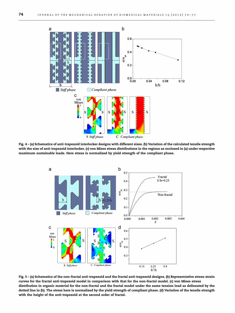
Fig. 4 – (a) Schematics of anti-trapezoid interlocker designs with different sizes. (b) Variation of the calculated tensile strength
with the size of anti-trapezoid interlocker. (c) von Mises stress distributions in the regions as enclosed in (a) under respective
maximum sustainable loads. Here stress is normalized by yield strength of the compliant phase.
Fig. 5 – (a) Schematics of the non-fractal anti-trapezoid and the fractal anti-trapezoid designs. (b) Representative stress-strain
curves for the fractal anti-trapezoid model in comparison with that for the non-fractal model. (c) von Mises stress
distribution in organic material for the non-fractal and the fractal model under the same tension load as delineated by the
dotted line in (b). The stress here is normalized by the yield strength of compliant phase. (d) Variation of the tensile strength
with the height of the anti-trapezoid at the second order of fractal.
j o u r n a l o f t h e m e c h a n i c a l b e h a v i o r o f b i o m e d i c a l m a t e r i a l s 1 5 ( 2 0 1 2 ) 7 0 – 7 774

Fig. 6 – Comparison of strengthening effect between anti-
trapezoid and saw-tooth designs (a) before and (b) after the
incorporation of structural hierarchy. For the cases studied
in (b), h/b¼0.038.
j o u r n a l o f t h e m e c h a n i c a l b e h a v i o r o f b i o m e d i c a l m a t e r i a l s 1 5 ( 2 0 1 2 ) 7 0 – 7 7 75
between the stiff and compliant phases in the lateral direction
becomes loose. Under external loading, lateral unlocking of two
phases will happen easily, giving rise to lower tensile strength of
the composites. Among the cases we considered, the highest
tensile strength is achieved when the shoulder width is taken
as 0.5h.
We proceeded further to study the effect of the anti-
trapezoid size on the tensile strength. Based on the discus-
sions above, we adopted the ratio w/h¼0.5. By varying the
anti-trapezoid height h (Fig. 4a), the effect of anti-trapezoid
size on tensile strength was investigated. Fig. 4b shows the
variation of the normalized tensile strength with the normal-
ized height h/b, where b stands for the width of the unit cell
as denoted in Fig. 4a. Within the range we studied (0.011rh/
br0.11), the smaller the joint size, the higher the tensile
strength. The maximum strength, which reaches as high as
49% of the ideal strength spb, is obtained when h/b¼0.011.
Such behavior of the tensile strength may be understood by
observing the stress and deformation at the critical
moments. Tensile yielding of the composites occurs either
due to interfacial separation or yielding of the compliant
material. Fig. 4c shows the stress distribution of all models at
their maximum stress states. It can be seen that no obvious
unlocking happens in these three cases. For the model with
large anti-trapezoid size, only a small portion of compliant
matrix yields and thereby the load-bearing capacities of
the component materials have not been fully utilized. With
decreasing interlocker size, the stress distribution in the
compliant layer tends to be more homogeneous and a
majority of compliant materials yield simultaneously, result-
ing in an increase in tensile strength of the composites. Here,
we achieved half of the theoretical tensile strength just by
interlocker size which is about 1/100 of the unit cell width.
Based on the trend shown in Fig. 4b, it is believed that even
higher tensile strength can be achieved with finer interlock-
ers, which would incur much higher computational cost and
therefore has not been attempted.
Inspired by the hieratical interlocking structures observed
on the interfaces in biomaterials, we investigated the effect of
hierarchy of interlocking structure on the tensile strength.
Based on the anti-trapezoid model mentioned above, we
created a self-similar (or fractal) anti-trapezoid model, as
shown in Fig. 5a. For comparison, the hierarchy was intro-
duced in such a way that the volume fraction of compliant/
stiff materials remains unchanged. Tensile strength was
explored for cases with various size ratios of h’/h, where h’ is
the height of the anti-trapezoid at the second order of fractal.
Fig. 5b shows the calculated stress–strain curve for the fractal
interlocker design with h’/h¼0.25 in comparison to that of the
corresponding non-fractal case. It can be seen that the tensile
strength can be enhanced by 57% by introducing structural
hierarchy on the interlocker. Fig. 5c shows the comparison of
the von Mises stress field for the fractal and non-fractal cases
under the same tensile load. It can be seen that the plastic
zone of the non-fractal case is much larger than that of the
fractal case under the same loading, implying that the fractal
structure can sustain higher loading than the non-fractal one.
The variation of the tensile strength with the ratio of h’/h is
shown in Fig. 5d. From the cases we studied, it can be seen
that larger h’ results in higher tensile strength.
3.2. Strengthening effects of the saw-tooth design
Besides the anti-trapezoid design discussed above, we also
considered the saw-tooth interlocker design (see Fig. 6),
which is also often observed in nature (Krauss et al., 2009;
Saunders, 1995). In order to make a comparison with the anti-
trapezoid case, we took the volume fraction of the stiff
materials F¼60% and the normalized teeth width w/h¼0.5
respectively. Fig. 6a shows calculated tensile strength of the
saw-tooth design as a function of the normalized tooth
height h/b. Like the anti-trapezoid case, Fig. 6a suggests that
the saw-tooth design with lower tooth height facilitates
higher tensile strength. In addition, the saw-tooth design
would provide even higher tensile strength in comparison to
the anti-trapezoid design with the same height. Likewise, the
effect of structural hierarchy was also investigated for the
saw-tooth design. As expected, structural hierarchy promotes

j o u r n a l o f t h e m e c h a n i c a l b e h a v i o r o f b i o m e d i c a l m a t e r i a l s 1 5 ( 2 0 1 2 ) 7 0 – 7 776
the tensile strength of the saw-tooth design as well, as shown
in Fig. 6b. In comparison to the anti-trapezoid design, the
saw-tooth design exhibits better strengthening capability no
matter structural hierarchy is present or not. Our computa-
tional results show that fractal saw-tooth interlocking design
can achieve tensile strength as high as 70% of the ideal value.
But this does not mean that saw-tooth design is the optimal
design. Other geometrical designs may exist with ability to
achieve even higher tensile strength.
Fig. 7 – Variation of the strengthening effect with coefficient
of (inter-phase) friction f for the anti-trapezoid design with
w/h¼0.5 and h/b¼0.11.
4. Conclusion and discussion
In this paper, we systematically investigated the interfacial
strengthening strategy for B-and-M composites through geo-
metrically interlocking design. Our results showed that
proper geometrical design of interlocker can effectively
strengthen the mechanical junction between the compliant
and stiff phases in the composites. As the best scenario in
our results, the fractal saw-tooth interlocking design was
found to be able to achieve the tensile strength of the
composites up to 70% of the perfectly bonded case; in
contrast, plain interfaces without any interlocking design
result in zero tensile strength. The present study has mainly
focused on the strengthening effect of interfacial interlocking
design. It should be of equivalent importance to understand
the effect of interfacial interlocking on other key mechanical
properties, including energy dissipation, toughness, impact
response and fatigue failure. For example, our case study also
illustrates introduction of hierarchy into the interlocking
designs would promote the energy dissipation by 20–25%.
Detailed discussion on the other properties would be made in
our future work.
In fact, mechanical interlocking, as a connection mechan-
ism, has been used for a long time even though quantitative
interpretation is little. For instance, prior to the advent of
cement the ancient Chinese architects used the rivet-and-
tenon structures (Fang et al., 2001) to connect the wooden
components (e.g. beams and pillars) to build some of the
ancient historical architectures such as the Forbidden City.
Recently, mechanical interlocking has also been used in the
emerging areas such as biomedical engineering and biomi-
metics. For instance, the connection between bone cement, a
type of man-made material for bone fixation, and the spongy
bone is effectively strengthened by mechanical interlocking
(Mann et al., 1998; Shang et al., 2006). The roughness of
ceramic surfaces was reported to enhance toughness of
artificial nacre through extremely efficient energy dissipation
(Launey et al., 2009). Our results presented in this paper
would be of great value to the improvement of the perfor-
mance of the interlocking designs in these applications.
It should be reemphasized that in our studies, we purposely
excluded other strengthening mechanisms such as the inter-
phase friction and adhesion caused by van der Waals interac-
tions, electrostatic force, and chemical bonding in order to
evaluate the strengthening contribution by interfacial interlock-
ing design solely. If one or some of these mechanisms are taken
into account, even higher strength is expected (Bruck et al.,
2004). For example, if we incorporate the friction between the
stiff and compliant phases in our simulations discussed above,
the variation of the tensile strength with the friction coefficient
is shown in Fig. 7. It is clear that friction helps promote tensile
strength. To achieve even stronger interface, other mechanisms
such as chemical grafting may be needed (Jackson et al., 1990;
Munch et al., 2008). It should be pointed out that strong
stiff/compliant interface may not always be beneficial for the
mechanical performance of B-and-M composites. As we know,
the operation of most toughening mechanisms in B-and-M
composites, such as inter-phase friction and pullout of stiff
phase from compliant phase, entails the failure of the interface
between stiff and compliant phases (Clegg et al., 1990). Interface
with over-high strength (e.g. perfect bonding) would prohibit
the occurrence of these toughening mechanisms, giving rise to
lower toughness of the composites. Therefore, high strength
and high toughness raise conflicting requirements for the
interface strength. There might be an optimal interfacial
strength, by which high strength and high toughness could
coexist in one B-and-M composite as they do in the natural
biomaterials. Exploration of such optimal interfacial strength
would be another topic of our future work.
Acknowledgments
YZ acknowledges the support of China Scholarship Council.
HY would like to acknowledge the support of the Grants for
Newly Recruited Junior Staff at the Hong Kong Polytechnic
University (Grant no.: A-PM24) and the Natural Science
Foundation of China (Grant no.: 11072273). CO acknowledges
the support of the US Army through the MIT Institute for
Soldier Nanotechnologies (Contract no.: DAAD-19-02-D0002),
the Institute for Collaborative Biotechnologies through Grant
no.: W911NF-09-001 from US Army Research Office, and the
National Security Science and Engineering Faculty Fellowship
Program (Grant no.: N00244-09-1-0064). MD acknowledges
the support from the Advanced Materials for Micro and
Nano Systems Programme as well as the Computational
and Systems Biology Programme of the Singapore-MIT
Alliance (SMA).

j o u r n a l o f t h e m e c h a n i c a l b e h a v i o r o f b i o m e d i c a l m a t e r i a l s 1 5 ( 2 0 1 2 ) 7 0 – 7 7 77
r e f e r e n c e s
Bonderer, L.J., Studart, A.R., Gauckler, L.J., 2008. Bioinspireddesign and assembly of platelet reinforced polymer films.Science 319, 1069–1073.
Bruck, H.A., Fowler, G., Gupta, S.K., Valentine, T., 2004. Usinggeometric complexity to enhance the interfacial strengthof heterogeneous structures fabricated in a multi-stage,multi-piece molding process. Experimental Mechanics 44,261–271.
Clegg, W.J., Kendall, K., Alford, N.M., Button, T.W., Birchall, J.D.,1990. A simple way to make tough ceramics. Nature 347,455–457.
Dunlop, J.W.C., Fratzl, P., 2010. Biological composites. AnnualReview of Materials Research 40, 1–24.
Fang, D.P., Iwasaki, S., Yu, M.H., Shen, Q.P., Miyamoto, Y.,Hikosaka, H., 2001. Ancient chinese timber architecture. I:experimental study. Journal of Structural Engineering 127,1348.
Fratzl, P., Jager, I., 2000. Mineralized collagen fibrils: a mechanicalmodel with a staggered arrangement of mineral particles.Biophysical Journal 79, 1737–1746.
Gao, H.J., 2006. Application of fracture mechanics concepts tohierarchical biomechanics of bone and bone-like materials.International Journal of Fracture 138, 101–137.
Gao, H.J., Ji, B.H., Jager, I.L., Arzt, E., Fratzl, P., 2003. Materialsbecome insensitive to flaws at nanoscale: lessons from nat-ure. Proceedings of the National Academy of Sciences of theUnited States of America 100, 5597–5600.
Geckeler, K.E., Rupp, F., Geis-Gerstorfer, J., 1997. Interfaces andinterphases of (bio)materials: definitions, structures, anddynamics. Advanced Materials 9, 513–518.
Hammer, D.A., Tirrell, M., 1996. Biological adhesion at interfaces.Annual Review of Materials Science 26, 651–691.
Han, L., Wang, L., Song, J., Boyce, M.C., Ortiz, C., 2011. Directquantification of the mechanical anisotropy and fracture of anindividual exoskeleton layer via uniaxial compression ofmicropillars. Nano Letters 11, 3868–3874.
Herring, S.W., 2008. Mechanical influences on suture develop-ment and patency. Frontiers of oral biology 12, 41.
Jackson, A.P., Vincent, J.F.V., Turner, R.M., 1990. Comparison ofnacre with other ceramic composites. Journal of MaterialsScience 25, 3173–3178.
Jasinoski, S., Reddy, B., Louw, K., Chinsamy, A., 2010. Mechanics ofcranial sutures using the finite element method. Journal ofBiomechanics 43, 3104–3111.
Ji, B.H., Gao, H.J., 2004. Mechanical properties of nanostructure ofbiological materials. Journal of the Mechanics and Physics ofSolids 52, 1963–1990.
Katti, D.R., Pradhan, S.M., Katti, K.S., 2004. Modeling theorganic–inorganic interfacial nanoasperities in a model bio-nanocomposite, nacre. Reviews on Advanced Materials Science6, 162–168.
Krauss, S., Monsonego-Ornan, E., Zelzer, E., Fratzl, P., Shahar, R.,2009. Mechanical function of a complex three-dimensionalsuture joining the bony elements in the shell of the red-earedslider turtle. Advanced Materials 21, 407–412.
Launey, M.E., Chen, P.Y., McKittrick, J., Ritchie, R.O., 2010. Mechan-istic aspects of the fracture toughness of elk antler bone. ActaBiomaterialia 6, 1505–1514.
Launey, M.E., Munch, E., Alsem, D.H., Barth, H.B., Saiz, E., Tomsia,A.P., Ritchie, R.O., 2009. Designing highly toughened hybrid
composites through nature-inspired hierarchical complexity.Acta Materialia 57, 2919–2932.
Li, Y., Ortiz, C., Boyce, M., 2011. Stiffness and strength of suturejoints in nature. Physical Review E 84, 062904.
Li, Y., Ortiz, C., Boyce, M.C., 2012. Bioinspired, mechanical, deter-ministic fractal model for hierarchical suture joints. PhysicalReview E 85, 031901.
Liu, B., Zhang, L., Gao, H., 2006. Poisson ratio can play a crucialrole in mechanical properties of biocomposites. Mechanics ofMaterials 38, 1128–1142.
Mann, K.A., Allen, M.J., Ayers, D.C., 1998. Pre-yield and post-yieldshear behavior of the cement-bone interface. Journal of Ortho-paedic Research 16, 370–378.
Munch, E., Launey, M.E., Alsem, D.H., Saiz, E., Tomsia, A.P.,Ritchie, R.O., 2008. Tough, bio-inspired hybrid materials.Science 322, 1516–1520.
Nalla, R.K., Kruzic, J.J., Ritchie, R.O., 2004. On the origin of thetoughness of mineralized tissue: microcracking or crack brid-ging? Bone 34, 790–798.
Ortiz, C., Boyce, M.C., 2008. Materials science—bioinspired struc-tural materials. Science 319, 1053–1054.
Podsiadlo, P., Kaushik, A.K., Arruda, E.M., Waas, A.M., Shim, B.S.,Xu, J.D., Nandivada, H., Pumplin, B.G., Lahann, J., Ramamoorthy,A., Kotov, N.A., 2007. Ultrastrong and stiff layered polymernanocomposites. Science 318, 80–83.
Rexer, J., Anderson, E., 1979. Composites with planar reinforcements(flakes, ribbons)—review. Polymer Engineering and Science 19,1–11.
Ritchie, R.O., 2011. The conflicts between strength and toughness.Nature Materials 10, 817–822.
Saunders, W.B., 1995. The ammonoid suture problem: relation-ships between shell and septum thickness and suture com-plexity in Paleozoic ammonoids. Paleobiology 21, 343–355.
Schmidt, D., Shah, D., Giannelis, E.P., 2002. New advances inpolymer/layered silicate nanocomposites. Current Opinion inSolid State and Materials Science 6, 205–212.
Shang, X., Tang, T., Dai, K., 2006. Experimental study on the shearstress of the interface between the bone and the TCP-PMMA.Journal of Medical Biomechanics 21, 111–114.
Tai, K., Dao, M., Suresh, S., Palazoglu, A., Ortiz, C., 2007. Nanoscaleheterogeneity promotes energy dissipation in bone. NatureMaterials 6, 454–462.
Tang, Z.Y., Kotov, N.A., Magonov, S., Ozturk, B., 2003. Nanostruc-tured artificial nacre. Nature Materials 2, 413–U418.
Wang, L., Song, J., Ortiz, C., Boyce, M.C., 2009. Anisotropic designof a multilayered biological exoskeleton. Journal of MaterialsResearch 24, 3477–3494.
Wang, R.Z., Suo, Z., Evans, A.G., Yao, N., Aksay, I.A., 2001.Deformation mechanisms in nacre. Journal of Materials Research16, 2485–2493.
Weiner, S., Nudelman, F., Sone, E., Zaslansky, P., Addadi, L., 2006.Mineralized biological materials: a perspective on interfaces andinterphases designed over millions of years. Biointerphases 1,12–14.
Yao, H.M., Dao, M., Carnelli, D., Tai, K.S., Ortiz, C., 2011. Size-dependent heterogeneity benefits the mechanical perfor-mance of bone. Journal of the Mechanics and Physics of Solids59, 64–74.
Yao, H.M., Dao, M., Imholt, T., Huang, J.M., Wheeler, K., Bonilla, A.,Suresh, S., Ortiz, C., 2010. Protection mechanisms of the iron-plated armor of a deep-sea hydrothermal vent gastropod.Proceedings of the National Academy of Sciences of the UnitedStates of America 107, 987–992.