Embed Size (px)
Citation preview

Bioengineering Techniques for Streambank RestorationA Review of Central European Practices
by
Martin Donat
Watershed Restoration Project Report No. 21995
Watershed Restoration ProgramMinistry of Environment, Lands and Parks
and Ministry of Forests
The formatting and images in this document may vary slightly from the printed version.

Bioengineering Techniques for Streambank RestorationA Review of Central European Practices
by
Martin Donat1
1 c/o o.oe. Umweltakademie, Stockhofstr. 32, A-4020 Linz, Austria Tel. 01143-732-7720-4407;Fax 01143-732-7720-4420
Watershed Restoration Project Report No. 2
1995

PREFACE
This review of bioengineering approaches to streambank and slope stabilization, asapplied in Europe, was produced to assist in the development of the Keogh River system(northern Vancouver Island) as a WRP demonstration watershed for the application ofrehabilitation techniques including streambank or slope stabilization. The techniques areprimarily of application to low gradient smaller streams and gullies typical of those withinthe coastal low-lands, including urban watersheds in the Georgia Basin, but also many ofthe more stable small salmonid nursery streams in the interior of British Columbia.Caution should be exercised by seeking local advice on which native vegetative species touse and by monitoring results on pilot sections. Traditional practices of stream bankstabilization in the Pacific Northwest have employed rip-rap revetment designs, and morerecently “tree retards” or rip-rap combined with geotextiles and re-vegetation. Also, it iscrucial to ensure that stream bank stabilization is coupled with techniques that restore fish-rearing habitat, and this review focuses specifically on erosion control. The B.C. Ministryof Forests’ Land management Handbook No. 18 (1994 edition) provides an instructivechapter (4) on hillslope protection and erosion control including suitable native plantspecies for grass seeding, wattling and staking. This report has been published within theWastershed Restoration Series as a technical reference (versus a procedural manual), but itis also applicable to habitat rehabilitation projects of the Urban Salmon Habitat Program,Salmonid Enhancement Program, Habitat Conservation Fund, and other related initiatives.
Bruce Ward Pat SlaneyFisheries Scientist Acting ManagerFisheries Branch Watershed Restoration Program
Copies are available from:
Watershed Restoration ProgramMinistry of Environment, Lands and Parks2204 Main Mall, University of B.C.Vancouver, B.C. V6T 1Z4

i
ABSTRACT
Donat, M. 1995. Bioengineering techniques for streambank restoration. A review of centralEuropean practices. Province of British Columbia. Ministry of Environment, Lands andParks, and Ministry of Forests. Watershed Restoration Project Report No. 2:86p.
The use of plants for river bank protection and erosion control has a long tradition in Europe.Recently, these old soil conservation and stabilization techniques have been rediscovered andimproved. These biotechnical engineering (bioengineering) techniques are summarized here.Developed by a system of trail and error, most of these techniques are based on long-term practicalexperience. These “soft” engineering practices can provide possibilities to complement, improve orin some cases even replace traditional “hard” river-training constructions, such as placement ofgabions or rock. These also offer a more ecologically acceptable way of bank stabilization that stillcompiles the land use and safety requirements. After a brief introduction to biotechnical engineering,the role of plants in riparian zones, their contributions to bank stability and plant-induced changes toflood run-off are discussed. The main part of this review is a detailed description and discussion ofthe most important biotechnical construction methods in streambank protection and watershedrestoration used in Central Europe. Aspects of maintenance of planted stream banks and an overviewon construction and maintenance costs conclude the report.
ACKNOWLEDGEMENTS
The author sincerely thanks Bruce R. Ward and Pat A. Slaney of the B.C. Ministry ofEnvironment, Lands and Parks, Watershed Restoration Program for giving me the opportunity tointroduce and discuss bioengineering methods used in stream restoration and enhancement in CentralEurope in this report. Additional thanks to Bruce R. Ward and Daiva Zaldokas for their help in theediting process of this review. It intends to offer some new perspectives on the development of riverengineering practices in British Columbia.

ii
Bioengineering Techniques for Streambank Restoration:
A Review of Central European Practices
A. INTRODUCTION .................................................................................................................... 1
A-1. Preface ............................................................................................................................. 1A-2. Biotechnical definitions................................................................................................... 1A-3. Benefits of biotechnical methods .................................................................................... 2
B. THE ROLE OF PLANTS IN RIPARIAN ZONES .................................................................. 4
B-1. Characteristics of riparian vegetation .............................................................................. 4B-2. Contributions of plants to bank (slope) stability ............................................................. 8
B-2.1. Mechanical and hydrological aspects of plants – overview................................ 8B-2.2. Soil reinforcement by plant roots........................................................................ 9
C. CONSTRUCTION METHODS ............................................................................................. 15
C-1. Brush-mattress construction ......................................................................................... 15C-2. Biotechnical constructions including geotextiles .......................................................... 16C-3. Fascines (bush wattles).................................................................................................. 21C-4. Wattle (wicker) fences................................................................................................... 23C-5. Live slope gratings......................................................................................................... 25C-6. Groove and cordon structures........................................................................................ 26
C-6.1. Groove (or rut) structures.................................................................................. 26C-6.2. Cordon construction.......................................................................................... 27
C-7. Layer structures ............................................................................................................. 28C-7.1. Hedge layer construction .................................................................................. 28C-7.2. Brush layer construction ................................................................................... 29C-7.3. Hedge-brush layer construction ........................................................................ 32
C-8. Placing of cuttings, wall joint plantings, vegetated stone walls and rock piles............. 33C-9. Crib wall constructions with branch layering................................................................ 36C-10. Vegetated gabions........................................................................................................ 38C-11. Vegetated palisades...................................................................................................... 39C-12. Branch layers in gullies................................................................................................ 40C-13. Transversal structures: Live ground sills, live bush and comb construction .............. 42C-14. Longitudinal structures ................................................................................................ 45
C-14.1. Groynes............................................................................................................ 45C-14.2. Log brush barrier and branch packings ........................................................... 52
C-15. Reed structures for bank and shore protection............................................................. 56

iii
C-15.1. Reed chump planting, reed rhizome and shoot planting.................................. 56C-15.2. Reed roll constructions (swamp sod rolls) ...................................................... 57
D. MAINTAINANCE OF STREAM BANKS............................................................................ 60
D-1. Introduction ................................................................................................................... 60D-2. General maintenance requirements ............................................................................... 61D-3. Initial care...................................................................................................................... 62D-4. Care and maintenance during plant development.......................................................... 62D-5. Long-term maintenance................................................................................................. 64
D-5.1. Mowing of dams and banks .............................................................................. 64D-5.2. Maintenance of trees and bushes ...................................................................... 69D-5.3 Removing of (other) hydraulic obstacles .......................................................... 71D-5.5. Rodent control................................................................................................... 71
E. CONSTRUCTION AND MAINTENANCE COSTS OF BIOTECHNICAL STRUCTURES............................................................................................................................................... 72
E-1. Introduction ................................................................................................................... 72E-2. Planning and construction costs .................................................................................... 73E-3. Maintenance costs ......................................................................................................... 75E-4. Summary........................................................................................................................ 77
F. REFERENCES ....................................................................................................................... 78
APPENDIX: “COMPOUND STRENGTH” OF ROOTED SOIL............................................... 82

1
Bioengineering Techniques for Streambank Restoration
A Review of Central European Practices
A. INTRODUCTION
A-1. Preface
The use of plants to secure banks along streams, lakes and beaches has a long tradition. Inthe Middle Ages banks of canals in France and the Netherlands were stabilized with willows. Inrivers of the Alps, structures of timber, rocks and plants have been used over the past centuries.Only in the first half of this century, however, have these old methods been rediscovered andimproved with new technical and biological knowledge. Today, there is a variety of biotechnicalmethods available to suit different situations and requirements. Biotechnical engineeringmethods have become part of geotechnical and hydraulic engineering and have helped bridge thegap between classical engineering disciplines, land use management, landscape architecture andbiological sciences.
In this review of Central European bioengineering practices, the different uses of plants inhydraulic and geotechnical engineering design are presented. A comprehensive overview ofbiological, ecological and technical considerations for the use of plants in engineeringconstruction is presented in the next five chapters, including: a brief introduction with generaldefinitions and goals of biotechnical construction methods, the ecological role of riparianvegetation, as well as attempts to quantify the impact of plants on stream hydraulics and bank(slope) stability. The core of this review is a comprehensive overview of the most importantbiotechnical construction methods used in river training and stream enhancement in CentralEurope. Methods, construction procedure, and the major advantages and disadvantages of thesebiotechnical methods are discussed. Suggestions for maintenance and final considerations aboutconstruction and maintenance costs conclude this review.
A.2. Biotechnical definitions
Biotechnical engineering techniques rely on biological knowledge to build geotechnical andhydraulic structures and to secure unstable slopes and banks. Whole plants or their parts are usedas construction materials to secure unstable sites, in combination with other (dead) constructionmaterial. Thus, biotechnical engineering does not replace traditional hydraulic or geotechnicalengineering (e.g. geotextiles, or concrete blocks), but complements and improves other technicalengineering methods.

2
The variety of construction methods can be classified according to purpose, material orconstruction characteristics. However, it is not always easy to distinguish between thesedifferent groups of biotechnical methods and strategies. Such a differentiation is often artificial,as similar techniques, with minor changes, are used in both, a classical geotechnical and riverengineering context. Biotechnical structures for soil stabilization are either point-by-pointsystems (structures of single root stocks), linear systems (structures of rows of root stocks) orcovering systems (surface-covering mattress of plant webbings). To design with any of thesesystems requires an understanding of the mechanisms they exploit in the building process itself.The material used and the purpose of the structure allows the techniques to be classified asfollows:
1. Surface protection methods (covering methods)2. Stabilization methods using live materials3. Methods combining dead and live material4. Supplementary methods5. Support structures using non-living material
Covering methods (1) are used primarily to provide quick surface protection for soilconservation. Securing of deeper soil layers are only secondary. By using a large number ofplants such as grasses and herbs per unit area, the soil surface is protected against erosion.Structures consisting only of live material (2) can improve slope stability and prevent erosion.Under less favourable conditions, support structures of non-living material may be required toaugment constructions made of living materials (3). Under extreme conditions (unfavourablesoil, extreme weather, short growing season), or if a site requires stabilization before live plantscan be used, materials such as timber, concrete, rocks and dead branches may be used as supportconstructions. In very wet sites or drainage areas with difficult access, biotechnical methods cansupport or even replace other methods. Biotechnical drainage systems act by decreasing pore-water pressures, thus avoiding soaking of cohesive soils and prohibiting inner erosion.Supplementary methods (4) are specific and effective methods to facilitate emergence of theclimax vegetation (e.g. plantings of single trees or soil improvement techniques). Thesetechniques are costly, and are therefore restricted in use.
A.3. Benefits of biotechnical methods
In comparison with traditional engineering techniques, the non-technical benefits of plantsare often stressed along with the usual technical advantages. Four general groups of benefits ofbiotechnical methods can be outlined:
1. Technical advantages:- protection against surface erosion- an increase of slope stability by root reinforcement and draining of the soil- protection against rock fall and wind

3
2. Ecological advantages:- regulation of temperature and humidity close to the surface, thus promoting growth- improvement of the soil water regime via interception, evapotranspiration and storage- soil improvement and top soil formation- improvement of and provision for habitat
3. Economic advantages:- reduction of construction and maintenance costs- creation of areas for agricultural and recreational use
4. Aesthetic advantages:- structures fit into the landscape- landscape is more appealing
These advantages make biotechnical techniques a worthwhile consideration in stream and bankrehabilitation. In the following chapters, these advantages are discussed in greater detail.

4
B. THE ROLE OF PLANTS IN RIPARIAN ZONES
B.1. Characteristics of riparian vegetation
Stream ecology requires the viewing of a stream and its surrounding land as a unit. Riparianzones are transitional areas between water and land, ecotones rich with elements of both.Vegetation is a key element in riparian zones that has numerous functions. Briefly, each of thesefunctions are discussed in further detail:
(a) Vegetation regulates the microclimate of streams(b) Vegetation secures banks(c) Riparian vegetation offers terrestrial habitat(d) Vegetation is a food source for aquatic and terrestrial life
(a) Vegetation regulates the microclimate on streams
Trees and bushes shade smaller streams, thus reducing temperature. Stream watertemperature of a creek changes with or without alders along throughout the course of a year(Fig. 1). On small creeks, the canopy can reduce sunlight in summer up to 80%.
Fig. 1: Temperature change of a stream with or without alder canopy cover (revised fromNiemeyer-Lüllwitz et al 1988)

5
Trees and bushes not only have an impact on the stream microclimate, but also inneighbouring areas. Dew formation, precipitation and soil moisture increase in their vicinity,while evapotranspiration and wind speed decrease (Fig. 2). Thus, vegetative cover can regulatesoil climate, stimulate soil activity through increased biomass production and act as a bufferagainst fertilizer and pesticide sprays. Trees and bushes slow down surface run off and filter finematerial (Rickson and Morgan 1988; Saupe 1992).
Fig. 2: Effects of tree and bush cordons on microclimate (revised from Wildermuth 1978)
(b) Vegetation secures banks
Vegetation slows water flow on banks and promotes sedimentation. If bank vegetation isboth flexible and a uniform thicket it can act as a flexible wall against flood flow (Fig. 3).
Fig. 3: Impact of vegetative covers on the distribution of flow velocities (BMLFW 1994)

6
Roots of flexible woody plants such as young willows and alders increase bank stabilization,while stiff or single trees may act like levers and cause progressive damage. Bank stabilizationproperties depend on various aspects such as plant species, age, stream morphology, soil, etc.The increases in slope stability provided by plant roots, as well as the impact of plants on flowcharacteristics are discussed in section B.2 and the appendices in more detail. (For detailedinformation on hydraulic calculations of streams with different vegetative covers see Felkel1960, Scheuerlein 1968, Lindner 1982, Pasche 1984, Rouve 1987, Bertram 1985).
(c) Riparian vegetation as terrestrial habitat
Riparian vegetation provides habitat and can be a food source for both aquatic species andterrestrial wildlife (Fig. 4). This is particularly true for landscapes with intensive land use wherestreams and small strips of vegetation often act as “ecological refuges”.
Fig. 4: Radius of activity (m) of selected wildlife species from vegetated stream banks inCentral Europe (revised from Wildermuth 1978)

7
(d) Vegetation is a food source for aquatic and terrestrial life
In the upper reaches of a stream the main food source is not in-stream primary production,but leaves and other organic material coming from outside the stream (Fig. 5). In larger, slowermoving streams, primary production within the stream becomes increasingly important withstream size, eventually replacing external organic input in the largest streams.
Fig. 5: Food web (functional groups) in a small creek (Donat, 1995)

8
B.2. Contributions of plants to bank (slope) stability
B.2.1. Mechanical and hydrological aspects of plants - overview
The influences of vegetation on slope (bank) stability can be divided into hydrological andmechanical mechanisms:
Hydrological mechanisms:
- interception on foliage (reduces rainfall by adsorption and evaporation)- infiltration capacity increased due to higher ground surface roughness and permeability- transpiration of water-uptake by roots lowers pore-water pressure- desiccation cracking of soil due to transpiration (cracks increase water permeability)
Mechanical mechanisms:
- soil reinforcement by roots increase shear strength- anchoring of topsoil into firm strata (buttressing and arching)- increase of surcharge by vegetation weight (increased normal and downhill forces)- dynamic forces (momentum) caused by wind led into the slope via vegetation (jack effect)- reduced erosion by dense root webs
Mechanisms beneficial to slope stability clearly outnumber adverse influences. Statisticalinvestigations have shown that, on bare slopes (without vegetation), failures occur more oftenthan in comparable slopes in wooded areas. For geotechnical calculations, increases in slopestability by evapotranspiration and other beneficial hydrological mechanisms have to beneglected, as they do not contribute under extreme, critical conditions (e.g. soil pores saturatedwith water). For stability calculations, the prime factor is mechanical soil reinforcement byroots. Depending on climatic conditions and special site requirements, appropriate deep-rootingplants are selected (see section B.2.2.l).
The situation of the critical sliding plane determines whether or not reinforcement by rootshas an influence on slope stability. There are four general cases for sliding planes parallel to thesurface (Fig. 6):
- Type A: A thin surface layer is reinforced, but the roots cannot penetrate the firm rock. Theboundary between the two layers is weakest where sliding can occur.
- Type B: Similar to type A, the plants reinforce the surface layer but also anchor it into cracksof the underlying firm strata.

9
- Type C: A thick surface layer is rooted with a transition zone towards the firm rock layer. Byanchoring the top soil to the denser transition zone with higher shear resistance, slope stabilityincreases.
- Type D: Root stocks “swim” on a deep surface layer and hardly contribute to slope stability.
Fig. 6: Slope classification scheme based on root reinforcement and anchoring (Tsukamotoand Kusakabe, 1984)
B.2.2. Soil reinforcement by plant roots
(a) Root volume characteristics
Growth and quality characteristics of the root system are both genetically fixed and sitedependent. One of the handiest and frequently used measures to express the geneticallydetermined soil-binding capacity of a specific plant root system is the root:shoot-volume ratio(Table 1). The ratio between the volume of rooted soil of a specific plant and the volume itsshoots require has been found to be roughly constant. This enables us to rank the suitability ofplants for a specific site (the higher the ratio the better) and to estimate the contribution of plantsto slope stabilization during plant development.

10
Table 1: Examples for root-shoot-volume ratio for different plant species (Schiechtl, 1973)
Plant species root/shoot volume Plant species root/shoot volume
Salix glabra 2.4 Anus viridis 1.5
Viburnum lantana 2.3 Fraxinus excelsior 1.5
Erica carnea 2.0 Acer pseudoplantanus 1.1
Salix eleagnos 1.8 Populus tremula 1.1
Salix nigricans 1.8 Salix alba 0.5
Salix purpurea 1.5 Populus nigra 0.4
Equisetum arvense 5.5 Festuca ovina 1.1
Rumex scutatus 5.0 Carex flacca 0.6
Petasites paradoxus 1.4 Calamagrostis epig. 0.5
(b) Root stocks characteristics
Although the shoot:root-volume ratio is an important biotechnical indicator, it gives noinformation about the type of the root system (root distribution). According to their geneticallyfixed root systems, plants can be classified as:
(a) Pants with extensive root systems (extensive-rooters): These plants develop a deep-reachingor/and wide-spreading root system, depending on the availability of water and nutrients (e.g.Salices sp., Petasites paradoxus, Epilobium angustifolium, Lathyrus silvestris, Medicago sp.).
(b) Plants with an intensive root system (intensive-rooters): These plants perforate the soilintensively and form sharply limited, shallow root stocks. (e.g. many copse forming grasses likeAchnatherum elatior, Calamagrostis sp., Care sempervirens, rhizome-forming pioneers andgravel-creeping herbs).
(c) Plants with mixed root system (mixed-rooters): Roots of mixed-rooters are wide-spreadingand extensive ranging with an intensive root horizons near the surface (e.g. Saxifraga sp.,Bromus sp., other gravel-covering and gravel-creeping herbs).

11
Although the distinctions between intensive-, mixed and extensive-rooters are general, theyare mainly used for herbaceous plants. For trees and bushes, the general distinctions between thedifferent root types is still valid, but needs some adjustment since wood plants have a secondarythickness growth and modifications in their root system. There is a general distinction betweenthree major groups of trees and bushes based on the shape of the root stock:
(a) Tap-rooters: plants with a deep-reaching, strong, perpendicularly expanding root system (e.g.Juglans regia, Pinus silvestris, Quercus pubescens, Taxus baccata).
(b) Heart-rooters: plants with an uniform, branched, half-spherical root system that form rootsthat explore the soil inclined downwards (e.g. Alnus glutinosa, Crategus monogyna, Larixdecidua, Quercus robur, Salix eleagnos, S. fragilis, S. nigricans, S. pentandra, S. purpurea, Tiliacordata).
(c) Flat-rooters: plants with dominating, sidewards growing, shallow main roots that exploresurface soil layers and from which, with increasing age, vertical roots spring off (e.g. Betulapendula, Picea abies, Pinus mugo, Populus alba, Salix alba, S. aurita, S. caprea, S. cinera, S.daphnoides, S. viminalis, Sambucus nigra, Sorbus aucuparia).
Although the type of root system and its basic characteristics are genetically determined, theactual root distribution and some additional characteristics depend on site conditions. Externalfactors with a possible impact on root growth include
- local soil conditions- altitude and latitude- availability of water and nutrients (i.e., reason for chemo- and hydrotropisms)- climatic factors- growth-restrictions (dense soil layers, layers with toxic substances)- seasonal changes (different vegetative cycles of root and shoot development)
The adjustment to local conditions is easier for plants with a phenotypic plasticity. Twoexamples are:
- Plants with deep-reaching roots on poor, dry sites with adverse conditions root the soil moreeffectively than when the same species is planted on sites rich in nutrients and moisture.
- In reaction to mechanical stress (caused by soil creep, coverage with gravel, erosion, rockfall,skinning snow) several species develop characteristic root formations (“mechanomorphosis”):anchor roots shaped like hooks or claws and supportive shoot- and root-horizons. Shrubs andbushes such as Rubus idaeus, Tussilago farfara, Salices sp. have the ability to form several roothorizons during repeated and frequent covering with gravel.

12
(c) Root strength parameters
The tensile strength of roots depends on the plants species, root diameter, age, site conditions(e.g. moisture) and season. Root tensile strength usually decreases with increasing diameter.Table 2 lists the range of tensile strengths for different groups of plants.
Table 2: Ranges of tensile strength for different groups of plants (Schiechtl, 1973)
Group of plants Average tensile strength
Grasses 5-10 MN/m2
Herbs 3-60 MN/m2
Woody plants 10-70 MN/m2 (max. 160)
The increase in shear strength of soil with increasing biomass content (weight of dry livingroots per soil volume) has been found to be roughly linear (Burkard 1987). After trees andbushes are cut down, the live root mass and the shear resistance decrease rapidly. When a bushlayer has re-established itself, the shear resistance returns to about three quarters of the originalvalue (Bourroughs and Thomas 1977).
(d) Other criteria for the selection of plants
The choice of plants for biotechnical structures does not only depend on root strengthcharacteristics but on factors such as:
- ecological amplitude (aspects of plant-sociology and plant-geography)- succession- propagation- growth qualities (speed and patterns of growth, juvenile growth behaviour), and finally- soil stabilization and anchoring qualities of the root system- physical and chemical soil characteristics- climatic aspects- other biotic aspects (toxicity considerations, etc.)

13
Considering these general plant characteristics only ensures the suitable vegetation materialis selected for a site and a construction method. For example, willows are probably the plantgenus most often used for geotechnical structures. There are large differences in characteristicsand plant requirements between the various willow species (Fig. 7 and 8). Only suitable plantmaterial guarantees a successful structure. The best reference are natural species and conditionsin a specific area.
Fig. 7: Distribution of European willows depending on altitude and soil conditions(Schiechtl and Stern 1994)

14
Fig. 8: Growth characteristics (height, shape) of mature, wild European tree and bushwillows (Schiechtl and Stern 1994)

15
C. CONSTRUCTION METHODS
In the following section the main types of biotechnical methods using woody or wet landplants or their parts are discussed. Surface covering methods such as seeding, hydroseeding, orrhizome plantings of herbaceous plants, as well as supplementary methods will not be dealt withher (for information see Schwab 1991). Biotechnical methods using willows and other woodyplants are especially appropriate for improving existing technical structures. The emphasis ofthis section paper is on construction of biotechnical structures and their use. The majoradvantages and disadvantages of each method are summarized.
C-1. Bush-mattress construction
In brush mattress-constructions (Fig. 9), the slope surface is completely covered with a denselayer of long and large, living branches or rods of sprouting material (usually willows)(notshorter than 1.5 m). The mattress of branches and rods is covered with top soil to facilitaterooting. In particular, the bottom end of the thick branches must be covered with soil, and reachthe water table of the stream. These bottom ends are secured with fascines, poles, woven fencesor rock packings – depending on the characteristics of the steam. Rods and branches are placedperpendicularly or inclined vertically 20°. If the length of the rods or branches is not sufficient tocover the whole slope, rods of the lower layer should overlap with the upper one by at least50 cm. The matting is fastened to the surface every 3/4 to 1 m with a network of wires, rods,fascines or woven fences.
Fig. 9: Brush-mattress structures (Schiechtl and Stern 1994)

16
advantages:- immediately effective after installation- dense root system and thicket developed- flexibility in reparation and protection of river banks- material easily available as structures also serve as a nursery for new plant material
disadvantages:- high demand on material and labour- occasional thinning of thicket necessary- labour intensive
Construction time: Only during dormant seasonCosts: 1 to 5 hours/m2 (depending on material availability and site conditions)Use: erosion control of banks and slopes, improvement of (underlying) riprap, bank repair.
C-2. Biotechnical constructions including geotextiles
Geotextiles within a biotechnical context have been used primarily to stabilize loose top soillayers until the roots of planted vegetation can take over (Table 3). It has been found at pioneersites that geotextiles can also function as a rough supporting and (permanent) reinforcement layerfor the root horizont itself. Use of geotextiles for slope and wall structures, supported by lifecuttings or branch layers has also become common. These combined geotechnical constructionscan replace woven structures, slope gratings, sometimes even rock securing (Fig. 10). They areused if a uniform plane of vegetative covering is desired, particularly when slopes are in dangerof erosion and instability (e.g., steepness >45°, easily weathering and falling rock, stream banks).Geotextile widths (webs) are placed with an overlap of only about 30 cm on each side and arefixed with hooks or pegs every m2.
Geotextiles used for biotechnical constructions are typically made of biodegradable materialssuch as jute, kokos, wood-wool, reed, flax, or synthetic fibres such as cellulose. They only lastuntil sufficient rooting is established. Geotextiles for long-term reinforcement are usually madeof UV-stabilized polypropylen or polyethylen, polyester or polyamids (nylon). Al geotextilesused close to the surface need sufficient resistance against ultraviolet radiation.
Design criteria for, as well as functions of geotextiles are summarized in the tables below(Table 4 to 7). They must meet the conflicting requirements of plants (porous, fine-meshed) andof geotechnics (filter-criteria). Plant growth and the penetration of these textiles by roots orshoots depend on:

17
- characteristics of the geotextile (pore diameter, thickness, structure, etc.),- site conditions (climate, altitude, exposure, precipitation, moisture, nutrients),- plants characteristics.
Following these plant-specific requirements and other general site characteristics, thefollowing parameters may determine the choice of geotextiles:
- slope of area to be secured- soil characteristics- weathering factors until overgrowth occurs- type of vegetation- time of planting- the duration until the development of a root-system occurs- drag-force of water (for hydrotechnical use)
Table 3: Geotextiles used for different biotechnical methods
type of geotextile biotechnical method used
coarse mesh textile (mesh diameter >5 mm) conventional surface seedingstructure mattress (coarse or fine) seeding, hydroseeding
planting of cuttings
fine mesh textile (mesh diameter ca. 2-5 mm) hydroseedingplanting of cuttings
special geotextiles (effective mesh size 0.5-1 mm) hydroseeding
standard fleece (effective mesh size 0.08-0.5 mm) hydroseeding restricted (pre-testsnecessary)
Structure mattresses are three-dimensional webbings of welded synthetic threads (e.g. nylon,mattress thickness: ca. 5-30 mm) which can be filled with (top) soil material or grit (eventuallycombined with bitumen). Plants root in or penetrate through such mattresses easily. Immediatevegetation is necessary for wide mesh systems to ensure a sufficient filter effect and protectionagainst surface erosion.

18
Table 4: Choice of geotextiles according to its use
use of geotextile usual type of geotextile
reinforcement of top soil and rootnetwork
textile, other lattice-like webbings structuremattress
protection against erosion fleece (with textiles), structure mattress
vegetating (standard seeding, hydro-seeding)
textile, structure mattress (use of thick, fine-porous geotextiles limited)
Table 5: Wear requirements for geotextiles
Resistance to wear by … max. reduction in tensile strength (%)
Case 1 Case 2
uv-radiation 5 5
biological influences(microorganisms)
25 5
chemical influences:acids 25 5bases 25 25
Case 1: geotextiles for short-term support of roots and protection of the soil against erosion until plants take over
Case 2: geotextiles for long-term support and erosion control

19
Table 6: Requirements for slopes endangered by erosion due to water or wind
max. efficient pore diameter of textile forsoil type slope angle(°) hydroseeding
immediately t < 2 months t > 2 months
cohesive < 40 (-) (-) (-)
> 40 (-) 4*d85 2*d85
non-cohesive < 35 8*d85a 4*d85 2*d85
> 35 4*d85 2*d85 1*d85
(-) no instruction regarding mesh diameter a time until hydroseeding or until sprouting of sod at standard seeding on the surface respectively
d85 … sieve diameter passed by 85% of the soil material
Table 7: Mechanical criteria for geotextiles
Use of geotextiles criteria
erosion control only tensile strength r>=6.0 kN/m (no punctual fixation)
soil stabilization tensile strength r>=10.0 kN/mexpansion under tension r>=20 %
for all uses minimum permeability k>=10-4 m/s (at normalpressure of 20 kN/m2)

20
Fig. 10: Different types of geotextile constructions with plant material (Donat 1995;Schiechtl and Stern 1992)
advantages:- immediately effectiveness- standardized material and calculation- can be combined with other techniques
disadvantages:- costly (material, labour)- use limited (restrictions for soil material, slope angle, wear, penetration)- limited height of geotextile constructions
Construction time: during dormant season if living branches are introduced; seeding or plantingof rooted material usually done in growing season; living pegs can also be driven in also aftercompletion of constructions.Costs: usually cheaper than other combined biotechnical methodsUse: surface protection (long or short term), wall constructions.

21
C-3. Fascines (bush wattles)
Fascines of sprouting material are placed in ditches (depth: 0.3-0.5 m: width: 0.3-0.5 m).The fascine should consist of at least 5 rods, each with a diameter of at least 1 cm. Fascines usedalong water courses are usually much thicker, as not all rods are bedded in soil or are able tosprout there. Similarly, fascines used for drainage purposes are thicker and placed straight downa slope. Slope fascines need not be bound as tightly (only every 3/4 m) as fascines used inwaterway constructions. The fascines are fixed with pegs (min. length 1/2 m of wood or steel,about 3/4 m apart, perpendicular to the surface). Rather than placing the pegs below the fascine(construction by Hoffmann), they now penetrate the fascine (construction by Käbel), thus savingon fixations. Finally, the ditches are refilled. Most of the fascines, but especially their endsshould be covered with soil.
Fig. 11: Manufacturing of fascines with or without rock core (Lange and Lecher 1993)
Fig. 12: Fascines for slope stabilization (construction pattern see also Fig. 16) (Schiechtland Stern 1992)

22
Fig. 13: Fascine variations for securing bank toes (Donat 1995; Schiechtl and Stern 1994)
Fig. 14: Fascines for drainage purposes (Schiechtl and Stern 1992)

23
advantages:- fast and simple construction- little soil movements- useful for wet slopes or zones- little reparations- promotes development towards climax
disadvantages:- flexible branches and rods necessary- susceptible to rockfall and shearing- little securing of deeper soil layers- labour intensive
Construction time: only possible during dormancyCosts: for geotechnical use: 0.5-1 hours/m; drainage river engineering structures: 1-3 hours/m.Use: Stabilization of top soil layers, slopes of fine material or bank toes, drainage of wet zones;securing of other brush layers (e.g. in sills, layer constructions, branch packings).
C-4. Wattle (wicker) fences
Wooden poles (1 = 100 cm; d = 3-10 cm) or steel pegs are driven into the soil 1 m apart.Between these pegs and poles, shorter (70 cm) poles of living material are driven in, and flexiblestrong rods of sprouting material are woven around them. The ends of the woven rods are struckinto the soil. Each pair of rods must be pressed down after being woven. Three to seven rods areplaced together. Alternatively, prefabricated rods or woven structures fixed on pegs can be used.At least 2/3 of the length of the pegs would be in the soil and their top ends should not stick outmore than 5 cm over the woven portion. The fences are partially covered with soil to enable atleast the bottom rod to root. Fences bedded totally in soil root are better than constructionsabove the surface. These fences can be placed as continuous horizontal rows or as diagonalfences in the shape of a rhombus. Wattle fences are used for securing dams and slope cuttings.They secure the top layer until the area in between is fixed by grasses, forbs, planted trees orbushes that root in deeper layers.

24
Fig. 15: Wattle (wicker) fences (Donat 1995)
Fig. 16: Rhombus construction pattern for woven fences (or fascines)(Pregl 1986)
advantages:- rooted fences retain and stop moving soil, and establish terraces- a flexible and rapid step towards a climax-like vegetation- easily combined with other methods
disadvantages:- high labour and material costs, and continuos control required- securing effect is small- large quantities of flexible branches are required (potential lack of local material)- easily damaged, thus not sufficient for persistent rockfall- frequently washed out when placed on creeks

25
Construction time: Only fences made during the dormant season sprout.Costs: 0.75 - 1.5 hours/meterWhile used extensively in the past, they are rarely constructed any longer because of their highlabour costs and the danger of erosion of fine material from behind the fence along watercourses.Use: Stabilization of top soil layers, slopes of fine material or bank toes, drainage of wet zones;securing of other brush layers (e.g. in sills, layer constructions, branch packings).
C-5. Live slope gratings
Gratings of wooden, metal, plastic or concrete poles (1.5 x 1.5 to 2.0 x 2.0 m) are fixed to theslope surface with living pegs or poles. These sprouting fixations and additional revegetation (byseeding or cuttings) in the grating-fields guarantees a long-term securing of the slope or slippage.Gratings may be built as three-dimensional double gratings: two gratings (as described above)form box-like compartments that are filled with layers of living material and porous soil. Liveslope gratings are used on extremely steep slopes or small slides, endangered by on-goingerosion, where conventional revegetation methods fail.
Fig. 17: Single and double live slope gratings (Donat 1995)

26
advantages:- fixation of top soil at extreme sites and makes revegetation possible- many variations and combinations possible- immediately effective on the surface and deeper- little maintenance
disadvantages:- high labour costs, and high material use (double gratings)- deep-reaching effect only occurs after rooting- usually used for smaller sites (max. height: 15-20 m)
Construction time: during dormant season, if livings material used; seeding is necessary duringgrowth seasonCosts: 2-5 hours/m2
Use: for vegetating and securing extremely steep surfaces (due to slides or side cutting)
C-6. Groove and cordon structures
C-6.1. Groove (or rut) structures
On the front edge of shallow ditches (width: 30-60 cm; depth of a spade), thin fascines ofliving material are fixed with pegs every meter (cf. slope fascine constructions). Behind thesefascines 1-2 small rooted trees or bushes are placed every meter. Then the ditch is refilled withmaterial dug out of the upper terrace and mixed with top soil, compost or a mixture of both (ca.50 1/m). To avoid slope failure by increased water retention, the ditches are not drawnhorizontally but inclined 10-30°, often z-shaped or in a herring-bone pattern. Groove structuresshould not be used on marl and clay soil.
Fig. 18: Goove (rut) constructions with and without additional securing (Donat 1995)

27
advantages:- good combination of water retention and drainage (depending on inclination)- initial and climax vegetation can be combined- moderate maintenance requirements- for reforestation of dry slopes and erosion control
disadvantages:- large amount of top soil required- high labour costs- not suitable for rocky and/or steep slopes
Construction time: only during dormant seasonCosts: 1-3 hours/meterUse: for plane, wet slopes with good growth conditions
C-6.2. Cordon construction
On a 0.5-1.5 m wide terrace, long poles of dead material are planted diagonally and coveredwith branches of conifers. This bedding is covered with about 10 cm of soil. Next, live cuttingsare placed on the terrace (2 to 3 cm apart, diagonally) and afterwards covered with soil. Workstarts at the bottom of a slope and makes its way up as the material dug out for the next ditch fillsup the lower terrace.
Fig. 19: Cordon construction (revised from Schiechtl and Stern 1992)

28
advantages:- use of machinery in shallow or moderately steep areas- good water retention capacity in dry climates- high sliding resistance- root aeration improved by branch layer- useful for steep and wet slopes of clay, also in limestone
disadvantages:- higher water infiltration undesirable on unstable slopes- high labour and material costs- sometimes reparation and fertilization necessary
Construction time: only during dormant seasonCosts: 3-4 hours/meter (most expensive method)Use: stabilization of instable slopes of cohesive and wet material
C-7. Layer structures
Layer structures are mainly used in side cuttings. Their construction is in principle more orless the same: 0.5-2 m wide berms or terraces (in steep terrain about 0.5 m deep ditches) arebuilt, starting from the bottom of a slope working its way up. Each of these terraces should beinclined with 5-10° towards the slope. The terrace lines are either horizontal or inclined up to60° to drain surface water. The berms are 1-3 m apart, depending on the slope and machineryused.
C-7.1. Hedge layer construction
On 0.5-0.75 m wide terraces rooted plants are placed side by side such that after refilling twothirds of their length will be covered with soil and the last third is above the surface. The plantsare covered with a thin layer of straw, bark compost or top soil to ameliorate poor or dry sites.For refilling, the material dug out from the next higher berm is used.Plant material for hedge layers are deciduous woody plants that can be buried and developadventive roots, and preferably 2 to 4 years old. For fast growing species (e.g. Alnus spp.) 2 yearold seedlings are often preferred. The sprout-to-root-ratio as an indicator of soil stabilizationcapacity strongly influences the choice of plant material.

29
Fig. 20: Hedge layer construction (Donat 1995)
advantages:- development towards forest climax accelerated- stabilization occurs immediately after construction
disadvantages:- large amounts of plant material required- high costs- mainly used at favourable locations (loess, gravel soils, sandy and clay soils in favourable
climates) and where willows are not available
Construction time: spring and fallCosts: 1-3 hours/meterUse: slope revegetation and stabilization of fertile soils or where willows cannot be used or arenot available
C-7.2. Brush layer construction
Starting at the slope bottom working upwards, 0.5-2 m wide terraces are dug out. On theinclined (ca 10°) planum branches are placed cross-wise (not parallel) such that only 1/4 mreaches above the surface. That way as much of the branches as possible are covered by soil forrooting, and a mixture of species and root horizons is achieved. The excavation material fromthe next higher terrace fills up the lower one.

30
Brush layers can also be built also during dam construction. The branches placed cross-wiseare longer (2-5 m) and covered with several soil layers till a new packing of plants is brought in.These branch layers provide a deep-reaching slope stabilization that cannot be provided by anyother biotechnical construction. At wet side cuttings terraces are inclined at 15 to 90 degrees toprovide better drainage. The brush layers should be more than 1.5 m (usually 2-3) apart to avoidlocal slope failures.
Variation:
To avoid erosion furrows and to reinforce the edge of the planum, about 1/4 m wide strips ofgeotextiles, roofing felt, boards or plastic foliage are placed below the branches. As this type ofconstruction is more sensitive to rock-fall, it is built starting from the top of the slope working itsway down. Other than that the construction is the same as before.
Fig. 21: Brush layer constructions (on existing slopes and during dam construction) (Donat1995; Schiechtl and Stern 1992)

31
advantages:- simple and fast construction with the deepest reaching maximal stabilization effect of all
construction methods (except hedge-brush layers)- all parts of a plant are used for construction- machinery use make construction simpler and less expensive- fast stabilization of cuts and fills at extreme sites- thick, high bush climax develops- used as a nursery for new plant material at the same time
disadvantages:- not suitable for retaining top soil (except variation method)- difficult to construct in existing slopes- most plant material must be dormant during construction- maintenance costs for pruning bushes- not to be used for slopes with deep top soil cover
Construction time: during dormant seasonCosts: 0.75-2 hours/meterUse: securing of side cuts and soil movements, revegetation of near-surface slides, especiallyused in torrent control and watershed restoration

32
C-7.3. Hedge-brush layer construction
The construction system is the same as for brush layers. However, to diversify the plantmaterial used and improve the success of the construction, some rooted, healthy plants (severalyears old shoots) are used in addition to the brush material and placed 0.5 to 1.0 m. apart on theterraces. Like the brushes, these rooted plants will be covered three quarters of their length withsoil after refilling of the terraces. The adventive root system that develops along the wholelength of the covered sprout parts provides additional fixation of soil material. Similar to brush-layer constructions, irrigation or the addition of top soil is not required, although they maypromote growth. Hedge-brush-layers with or without longitudinal reinforcement strips areprimarily used to secure side cutting slopes, local small slides and landfills.
Fig. 22: Hedge-brush layer constructions (revised from Schiechtl and Stern 1992)
advantages:- same as for brush layers- two stages of re-vegetation by rooted and unrooted material- more technically effective
disadvantages:- not suitable for retaining top soil (except reinforcement variation)- maintenance costs (cutting out of branches)- more difficult to establish on existing slopes

33
Construction time: during dormant seasonCosts: 0.75-2.5 hours/mUse: like brush layer construction, but rooted material allows wider use
C-8. Placing of cuttings, wall joint plantings, vegetated stone walls and rock piles
Two to ten healthy, cuttings per square meter (one to several years old, length: 0.5-1 m,diameter: 1-5 cm) are driven into the soil perpendicular to the surface up to three quarters of theirlength. Injuries to the bark of these cuttings during construction stimulates root-formation. Forjoint plantings, cuttings are placed in dry stone walls or rock-pavings after construction. Theplant loss is about 30 to 50%. For vegetated stone walls and rock piles the sprouting material isbrought in during the construction. The diameter and length of the cuttings is much bigger thanof the plant material used for simple placement cuttings.
Fig. 23: Cuttings (Donat 1995)
Fig. 24: Planting of slope drainage constructions (revised from Schiechtl and stern 1992)

34
Fig. 25: Joint planting of rock pavements and groynes (revised from Schiechtl and Stern1994)

35
Fig. 26: Planting of riprap (Donat 1995; Schiechtl and Stern 1994)
advantages:- inexpensive and fast method- excellent stabilization and aesthetic effect- used to improve existing structures- almost no maintenance- a method of planting in moist slopes for controlling wind, water and avalanches erosion- plant material for vegetated stone walls and rock piles has less requirements regarding shape of
cuttings than other plantings- wall constructions are flexible and can be reused possible if it fails

36
disadvantages:- stabilization occurs only after rooting- construction only possible during dormancy- planting of completed constructions (walls, stone packings, etc.) is often difficult- growth is restricted to certain species- height of wall structures is limited- wall structures labour intensive (other placements are not!)
Construction time: during dormant seasonCosts: 0.05-0.1 hours/cutting, planting of cuttings: 5-7 m2/hour, joint plantings: 2-4m2/hour(including additional work and harvest of cuttings)Use: Vegetation of bare slopes; revegetation of technical structures, support method to drainageconstructions.
C-9. Crib wall constructions with branch layering
Longitudinal elements and cross beams of wood, concrete, steel or plastic material (diameter:10-25 cm) are placed on each other alternately and joined to form a single or double, box-likecrib wall (width: 1-1.5 m). The structure is filled with gravel and soil material, with layers ofliving branches in between at an angle of 10°. The ends of the branches reach about 1/4 m out ofthe crib wall and stick into the native soil material on the other end. The living material offersadditional anchoring, long lasting fixation of soil material and a water pumping effect of thefoliage by evapotranspiration.
Fig. 27: Vegetated crib walls for slope stabilization (revised from Schiechtl and Stern 1992)

37
Fig. 28: Vegetated crib wall for bank protection and restoration (also used for sillstructures) (revised from Schiechtl and Stern 1994)
Fig. 29: Vegetated crib walls from dam-like structures in streams and tributaries (revisedfrom Schiechtl and Stern 1994)
advantages:- short construction time, fast stabilization- simple foundation (slope of foundation important for concrete crib walls)- “elastic” and effective structure for critical points- if planted, aesthetically appealing
disadvantages:- high material costs, especially for prefabricated crib walls (except for wooden crib walls)- durability of lumber limited- choice of filling material is a trade-off between filter criteria and plant requirements- limited construction height

38
Construction time: during dormant seasonCosts: comparable to dry stone walls (except wooden crib walls!)Use: Slope and bank stabilization (toes, side cuts), dam-like structures for slowing downsediment transport in tributaries
C-10. Vegetated gabions
Gabions are rather stiff boxes or flexible rolls of close-meshed wire filled with coarse gravel.Between gabion boxes and within them, living branches are introduced to root in both the gabionand the surrounding soil. If gabions could be displaced by mechanical forces, they are fixed withdeep-reaching metal poles. Combinations of gabions of different shape and dimensions areeasily possible. Similar to other structures, the decision which soil material should be used isalways a trade-off between filter criteria and requirements of the vegetation.
Fig. 30: Vegetated gabions (revised from Schiechtl and Stern 1992)
advantages:- fast, simple and common construction method- elastic structure with multi-purpose use, can be combined with other structures- used for unstable slopes endangered by erosion, especially along streams or in debris areas- no danger of water impoundment, used also for wet sites with fine soil material

39
disadvantages:- gravel and rocks necessary (trade-off between plant-and filter requirements)- vegetating after construction of the gabion is difficult- height restriction- gabions without vegetation or relatively smooth surfaces act as “guide-rails for water” if used
for securing of stream banks
Construction time: during dormant season (later vegetating hardly possible)Costs: inexpensiveUse: like crib walls (C-9), especially where debris available
C-11. Vegetated palisades
Living, uniform stakes of live material are driven into the soil (one third of their length) sideby side to form a palisade. The top ends are cut plane and tied to a horizontal (living or dead)pole that ties in the ground at both sides of the gully. Pallisades are used to promote depositionin V-shaped gullies and rehabilitation in fine soils (clay, sand, loess, loam).
Fig. 31: Vegetated palisades (Schiechtl and Stern 1992)

40
advantages:- quickly and easily built- immediately effective, usually grows well- filter effect- evapotranspiration reduces pore water pressure
disadvantages:- limited width (about 6m) and length (2-4 m)- availability of material restricted (long, straight poles)- only for restricted water and debris flow
Construction time: during dormant seasonCosts: cheap if material at site is availableUse: reduce slope in gullies and tributaries, encourage deposition of sediments especially in finesoils
C-12. Branch layers in gullies
Live branches are placed in gullies in a fish-bone pattern with their tops up. When livingbranches are lacking, conifer branches can be used (which will not sprout). This branch mattressis fixed every 2 m with horizontal cross-pieces (poles) that bind in on both sides of the gully.The branches are covered by soil material to encourage sprouting. Branch layers are used forrehabilitation of gullies to stop progressive erosion. These ditches with or without permanentrun-off may be up to 8 m wide and a maximum of 3 m deep.
Fig. 32: Branch layers in gullies (Donat 1995)

41
advantages:- continued effectiveness (live plants)- usually no maintenance- succession easily introduced- particularly suitable for shallow gullies
disadvantages:- construction with live material slightly more expensive than dead branches- not suitable for severe bed movement (only for moderate and/or periodic transport)
Construction time: only during dormant seasonCosts: relatively cheap if branches are at handUse: up to 3 m deep gullies with permanent or intermittent water flow and sediment transport;against progressive erosion

42
C-13. Transversal structures: Live ground sills, live brush and comb construction
For live bush ground sills cuttings are placed in the fugues of a ground ramp. If thesecuttings are planted only in the stream bed they are called live brush and comb constructions.For another variation, shallow ditches (1/4 to 1/2 m deep) are dug out, living brushes (1 to 1.5 mlong) are placed crosswise, in flow direction with their thicker end in the ditch. The branchesform a dense brush without any gaps to avoid local erosion later on. The branches are coveredwith some fine material to promote rooting and are secured by rocks or pegs (live brush groundsills), live or rock-filled fascines (live fascine ground sills) or gabions (live gabion ground sills).Then the branches are covered 1/2 or 2/3 of their length with bed material.
The sill construction (especially the live fascines) extends at least 1.0-1.5 m on each side intothe stream banks and is secured there. The root of the sill in the banks is planted in addition totechnical reinforcement with cuttings. The downstream side needs extra securing with largerocks and live branches that brake the energy of the water in case of an overflow. Single ordouble fascine constructions are common and can be packed with additional rock and branchmaterial, then reinforced with pegs (every 0.5 m) and steel ropes, if necessary. Fascines sills aremore stable than regular brush sills. A combination of woven fences and fascines or fences andbrushes is also possible, although they are not very persistent. Immediately downstreams of sillsbanks must be secured with dense brush mattresses (wired down).
Fig. 33: Different types of sills (revised from Schiechtl and Stern 1994)

43
Fig. 34: Fascine sills (Donat 1995)
Fig. 35: Block-brush sill (revised from Schiechtl and Stern 1994)

44
Fig. 36: Crib wall ramp (revised from Schiechtl and Stern 1994)
advantages:- simple, fast, and rather cheap construction- many variations and combinations of sills with other methods possible- provides structuring of stream bed, especially water line- promotes sedimentation- resistant (up to 150 N/M2), recovers after damage- maintenance simple
disadvantages:- limited to smaller gullies and ditches with flush floods- not to be used in torrents with heavy bed load- reinforcement is necessary (depending on the flow characteristics)- not very stable (only for low land streams and upper tributaries to torrents)- usually in streams or vadis not wider than 5 m
Construction time: during dormant season at low water flowCosts: cheap construction techniqueUse: slow down sediment flow in tributaries to torrents, stabilize bed of small creeks

45
C-14. Longitudinal structures
Longitudinal construction methods encompass single or a sequence of local structure alongstream banks (e.g. groynes, structures for repairing local bank failures), and secondly linear (orlongitudinal) structures. This second group of methods uses mainly grass species (e.g. Carex,Phragmites, Phalaris, Typha) instead of the willows normally used for biotechnical constructions.
C-14.1. Groynes
Groynes are transversal structures extending from the stream banks into the stream to securethe banks by redirecting the flow and transforming flow energy. While linear longitudinalstructures secure banks on the whole length, groynes only limit stream courses (wider than 10 m)locally. They are either built inclined (repelling), declined (attracting) or rectangular (deflecting)to the flow, and vary considerably with stream characteristics and the material used.
Fig. 37: Construction principles of groynes (Ehrengruber 1989, revised)
Fig. 38: Basic groyne patterns (Ehrengruber 1989, revised)

46
Declined (attracting) groynes (pointing in flow direction; β = ca. 45°) are rare, because theyact like sills when subjected to overflow during floods and can cause damage on the banks.Inclined (repelling) groynes point against the flow direction (angle α = usually 60-85°), directingthe flow towards the middle of the stream (even during floods) and thus acting like weirs. Ifgroynes are built on both sides of a stream, their heads (tips) are placed opposite each other,otherwise the flow swings in the areas between the groynes.
Fig. 39: Impacts of groynes on stream bed morphology (Kern 1994, revised)
The length of groynes depends on stream width, required hydraulic capacity, the availablematerial, and the purpose of the structure. Short groynes require smaller distances in betweenthan longer ones. If they are too short, other continuous, longitudinal structures or bankprotections are cheaper and more effective. For diversifying stream habitat, a length of up to 1/3of the stream width has proven useful. For bank protection, the correlation between the lengthof, and distance between groynes are discussed below.
Fig. 40: Flow characteristics between groynes (Lange and Lecher 1993, revised)

47
Groynes that reach above water level at medium or low flow cause two types of eddies thatpromote the formation of potholes near the head and deposition of fine material in the interface.The separation beam runs at an angle β of about 6°-15° into the area between groynes (Langerand Lecher 1989, Aulitzky 1990). Similar to length considerations, estimates of the distancebetween groynes depends on their purpose and overall structural concept:
a. sequence of singular groynes:
If groynes function on a one by one basis, the separation beam should hit the next groyne inthe middle of its length.The distance d of these groynes can be estimated as
d = f * 1 * sin (α - β)
d … distance between groynesl … length of groynesα … angle of groyneβ … angle of separation beam (6-15°)f … factor
For bank securing: 4.5 to 4.78 (commonly used estimates)1 to 2 (Duhm 1946)2.5 (for redirecting flow)f*1 = 0.25 to 1 times stream widthIn bends, on outside: f*1 = up to 0.5 times stream width
For restructuring: 5 to 7 times medium stream width (Wesche 1985)5 to 10 times medium stream width (Frauendorfer 1985)
Fig. 41: Flow characteristics between groynes (Lange and Lecher 1993, revised)
b. sequence of interdependent groynes:
If a sequence of groynes should act as composite structure instead of a sequence of singlestructures, they should be positioned at such a distance so that the main flow (beam) does not hitthe next groyne, but rather the back flow of its eddy. In such sequences the potholes behind the

48
first groyne is deeper than behind the following ones. Thus, the first groyne needs extrasecuring. Estimates are done for the bed forming water flow.
Fig. 42: Graphical estimation of bed forming water level of streams (Lange and Lecher1993, revised)
The groyne head needs special securing: in riprap groynes the largest single rock must beplaced at the tip and be founded in the natural pavement of the stream bottom. The level of thecrest of groynes depends on their function: If groynes are built to regulate low water flow, thecrest is at the low water mark. For bank protection purposes, the crest is usually at mediumwater level or at the level of the bed-forming flow (see above). Higher groynes are used torestructure banks. The crest should be secured to avoid damages during floods.
Groynes are sloped upstream 1:2 to 1:3 and downstream 1:3 to 1:4. The slope of their headtowards the middle of the stream varies (usually between 1:4 to 1:10). The crest is slopedtowards the banks (1:10 to 1:100) and the structure secured there wide and deep enough.
Groynes can be made of sheet walls (steel, steel-concrete, wood), gabions, pallisades,fascines (with or without rock fillings), rock packings, concrete elements (e.g. tripods), crib wallstructures or a combination of these. The actual choice of material and structural design dependsmainly on the kind of material available at the specific site. Biotechnical engineering introducesplants in these structures above the mid-water level. In addition, cuttings are introduced betweenthe blocks. If potholes are to be prevented, additional live brush, cuttings or reed are placed onthe downstream side beneath the mid-water level to help brake the flow. The interface betweenthe groynes can be filled with comb-structures made of live brushes or cuttings to promotesedimentation.
Two main types of groynes are commonly used: box-shaped and riprap. Box-shaped groynesare cribwall-like structures of timber or steel, rock and live plant material. Geotextiles are to

49
keep fine material in place to enable plants to sprout. Rocks for riprap groynes can be eithertipped or placed. Placed riprap reduces the amount of rock needed and forms a more reliablestatic structure.
Groynes reduce both the cross-sectional area of a stream and the hydraulic capacity, as wellas slow down the mean flow. The Manning-Strickler coefficient kst is reduced in average by 5-15% (Bechteler and Vollmers 1988). As groynes direct the main flow into the middle of astream, they reduce bank erosion and promote sedimentation (especially hook- or T-shapedgroynes). They are used to stabilize or restore banks and redirect the flow to diversify streamhabitats.
Fig. 43: Riprap groynes (Lowe 1992)
50
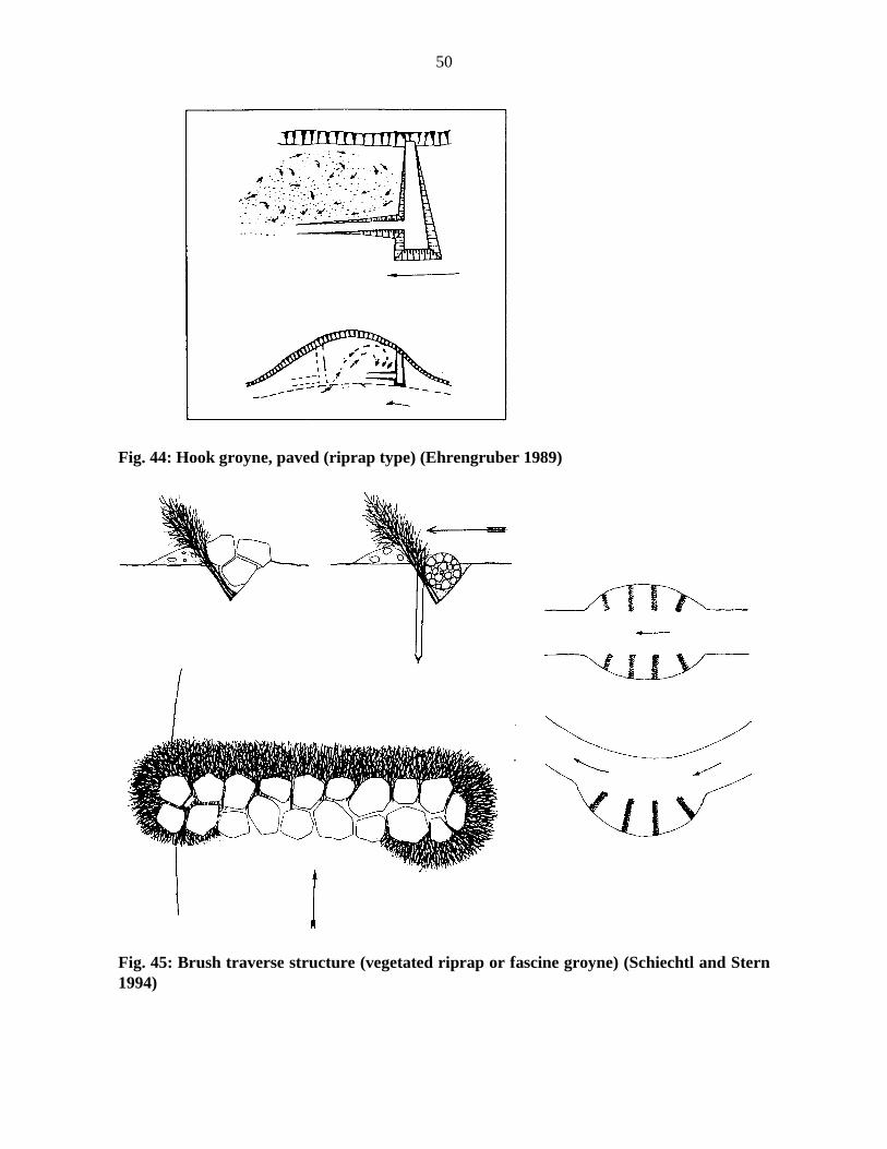
Fig. 44: Hook groyne, paved (riprap type) (Ehrengruber 1989)
Fig. 45: Brush traverse structure (vegetated riprap or fascine groyne) (Schiechtl and Stern1994)

51
Fig. 46: Wooden (box) groyne (Waltl 1948)
advantages:- simple, traditional, very resistant, and immediately effective construction- directs flow, diversifies choriotops of a stream and promotes habitat heterogeneity- requires little maintenance- reinforcement and later changes are possible- numerous variations and combinations with other structures are possible
disadvantages:- can be constructed only during dormancy- minimum width of streams is 10 m (in narrow streams only for diversification of alignment)- not all variations are suitable for mountain creeks (reinforcement necessary)- cross-sectional flow and eddies can’t cause bank damage during overflow (cf. declined
groynes)
Construction time: during low flow, usually during dormant seasonCosts: cheaper than continuous riprapUse: securing of banks, redirecting water flow, encourage diversification of stream morphology

52
C-14.2. Log brush barrier and branch packings
Log brush barriers combine several biotechnical methods to the restore more severe bankdamage. Beginning at the top and proceeding in the flow direction, a log brush barrier is erected.Then, the future water line is marked with wooden stakes (2-3 m apart). In both, the area markedby the stakes and the present bank, big dead branches and small trees are laid perpendicular tothe flow direction, with their thick ends towards the banks. Their tips are to reach 1/2 to 3/4 mover the stake line into the stream. The thickness of this bottom layer depends on the waterdepth at the site.
Next shorter live branches are set into the stream bed, inclined towards the middle of thestream. For stability reasons, the branches should form a very dense and deep reaching brushnear the stakes. This branch mattress is weighted down with bigger rocks every 1 to 1.5 m.Perpendicular to these first branches and parallel to the future shore line live branches (inclinedin flow direction) form a second layer. If there is a lack of live material, the branches can formrows with dead branches or bed material in between. This second brush layer is secured withrocks like the first. The first part of the structure (where the bank failures starts) must becarefully secured with rocks. Both brush layers together should reach about 1 m above the lowwater level. The remainder of the damaged banks should be covered with a brush mattress toprevent further erosion.
Larger bank failures do not need to be filled with log brush barriers completely. It issufficient to secure the first quarter with this construction and encourage sedimentation in the restwith brush sills every 4 m with brush-comb structures occurring in between.
Fig. 47: Log brush barriers for large bank failures (Schiechtl and Stern 1994)
53
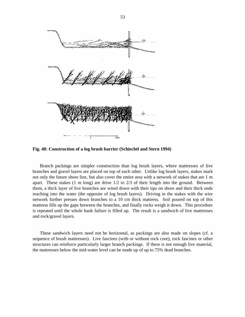
Fig. 48: Construction of a log brush barrier (Schiechtl and Stern 1994)
Branch packings are simpler construction than log brush layers, where mattresses of livebranches and gravel layers are placed on top of each other. Unlike log brush layers, stakes marknot only the future shore line, but also cover the entire area with a network of stakes that are 1 mapart. These stakes (1 m long) are drive 1/2 to 2/3 of their length into the ground. Betweenthem, a thick layer of live branches are wired down with their tips on shore and their thick endsreaching into the water (the opposite of log brush layers). Driving in the stakes with the wirenetwork further presses down branches to a 10 cm thick mattress. Soil poured on top of thismattress fills up the gaps between the branches, and finally rocks weigh it down. This procedureis repeated until the whole bank failure is filled up. The result is a sandwich of live mattressesand rock/gravel layers.
These sandwich layers need not be horizontal, as packings are also made on slopes (cf. asequence of brush mattresses). Live fascines (with or without rock core), rock fascines or otherstructures can reinforce particularly larger branch packings. If there is not enough live material,the mattresses below the mid-water level can be made up of up to 75% dead branches.

54
Fig. 49: Branch packings (BMLFW 1993; Donat 1995; Schiechtl and Stern 1994, revised)

55
advantages:- immediately effective restoration of bank failures with increasing effectiveness over time- prevents progressive erosion, promotes siltation and restructures water and shore line- used in fast running streams with variable flow of water and bed load- aesthetically appealing- can be combined with other methods
disadvantages:- higher labour costs- large amounts of live material needed- only up to 3m water depth- built only during dormancy
Construction time: during dormant seasonCosts: medium, about 25-50% of the costs for hard methods (e.g. riprap)For branch packings: 5-10 hours/m (1 m high, 4 m wide)Use: restoration of bank failures

56
C-15. Reed structures for bank and shore protection
C-15.1. Reed chump planting, reed rhizome and shoot planting
For reed structures, ditches or holes are dug out. Reed mace, reed, and rushes should beplaced a bit (10 to 15 cm) below the mid-water mark in summer, with sedges and other swampplants a bit above that level. These ditches or holes can also be spared in existing riprap or otherbank protection structures. Root chumps of reed, their rhizomes or shoots (Phragmitescommunis) and other swamp plants are placed in a ditch or holes along the stream banks or lakeshore. For shoot plantings, 3 to 5 shoots are stuck into the ground every 0.25 to 0.5 m using adrill. The shoots are introduced shallow enough that the top ends remain close to the surface andadventive roots can form at the joints.
For rhizome and chump constructions, at least 30x30x30 cm big roots stocks or rhizomebundles are dug out. Roots (rhizomes) and surrounding soil are wrapped in decomposabletextiles (e.g. jute) and the young shoots are protected against damage during transport. Thechumps in the textiles are placed side by side about 0.5 m from the water line. The plantedshoots or the placed chumps are covered with gravel and sand, then secured with a few rocks.The roots must reach fertile soil for the rhizomes to spread. In riprap structures sand, soil andfine gravel must be filled in the prefabricated ditches or holes to enable sprouting. Young,healthy reed haulms, about 1 m long (with only leaves) are cut off close to the surface. Thevulnerable haulms are transported bundled and wrapped in textiles to the construction site.
Fig. 50: Reed constructions along shores and banks of slow flowing streams (Schiechtl andStern 1994, revised)

57
advantages:- simple and cheap construction- propagation easy in silty-sandy soil- tolerant species (except in shadow)- natural feature on lakes, ponds, canals and streams with slow flow
disadvantages:- construction possible only during a short time of the year- transportation costs (weight)- no immediate protection; not for sites with direct wave impacts- difficult to control growth- intolerant of shady sites
Construction time: root stocks and rhizomes usually during dormancy, before sprouting in spring(March/April); for fast replanting all year long;Shoot plantings only beginning of May until mid JuneCosts: 1-3 hour/m2
Use: revegetation and protection of shores of lakes and slow flowing streams
C-15.2. Reed roll constructions (swamp sod rolls)
Stakes (1-1.5 m long, 1-1.5 m apart) are driven into the ground along the mid-water mark insummer, until only 30 cm reach above the water. Behind this line, a ditch (0.5 m deep, 0.5 mwide) is dug out and secured with boards, if necessary. In this slot about 1.5 m wide mesh wireis placed for the roll. The gap between the roll and the ditch wall is plugged by the materialfalling through the mesh during filling. The fill is a mixture of medium and coarse gravel withrests of reed chumps. If the mesh is covered with branches first, the bottom fifth can be filledwith material dug out earlier. The top fifth consists of reed chumps. After filling the mesh wireit is pulled together to form a roll. The boards on the walls of the ditch are removed, the gapsrefilled and the stakes are driven in to match the crest of the roll. The completed roll should stick5-10 cm out of the water. For bigger bank failures gravel fascines or riprap with additional brushlayers can act as a foundation of reed rolls.

58
Fig. 51: Reed roll constructions (Donat 1995; Schiechtl and Stern 1994, revised)

59
advantages:- most stable reed construction- almost no maintenance- immediate protection after construction- resistant to water pollution
disadvantages:- higher costs (labour!) than simple reed plantings- possible construction time limited
Construction time: during dormant season; especially early springCosts: 4-6 hours/mUse: revegetation and protection of banks of lakes or slow flowing streams

60
D. MAINTAINANCE OF STREAM BANKS
D-1. Introduction
In cultivated landscapes, streams and their tributaries are remainders of former naturalsystems. However, even such an apparently natural water course is usually altered by changes inland use in its immediate vicinity, as well as in the entire watershed. Streams in a cultivatedlandscape require care and maintenance. This is particularly true for streams re-structured andrestored from channels formerly degraded by land use requirements and designed following onlytechnical standards. Important aspects for the structural quality of natural reaches of streamsinclude
- the unity of the stream and riparian zone- linking of different biotops, reaches and corridors- stream bed dynamics (dynamics of water flow and sediment transportation)- diversity of substrates, choriotops, structures and vegetation- unique patterns of (land) use in different watersheds.
River training works, as technical answers to land use conflicts, often restrict streams to acertain (modified) channel. That reduces potential stream development and cuts down onmorphological and structural stream quality. Ecological improvement of such altered reaches areoften restricted to measures on the waterline or in the immediate riparian zone. Biotechnicalmethods are examples for more biologically sensitive approaches to stream bank protection anddesign, where these methods are also acceptable from an engineering point of view.Nevertheless, they are methods to help secure banks and technical structures and, with somevariations, maintain a certain “status quo”.
While the principal goal of maintenance in such altered stream systems is usually to maintaincertain technical conditions, it can also be a tool to influence and improve the ecological qualityof reaches and diversify habitats. Thus, maintenance plays a key role in the development ofdiverse, semi-natural systems in an increasingly cultivated landscape.
Maintenance measures often try compromises between technical and safety requirements andthe long-term need to guarantee a certain minimum of “ecological functioning” of streams. Non-recurring and recurring measures to meet technical, economic and ecological goals in specificareas or on specific reaches are prescribed stream maintenance plans. Type, technique, timing,frequency, and duration of specific measures to reach a certain set quality goal are discussed andlisted in these reports.
61
Overly detailed maintenance plans have proven not to be practical and incur high costs.Short prescriptions and a regular training of the people doing the maintenance work arecommonly regarded to be most effective. The following section discusses some of theconsiderations regarding maintenance of riparian vegetation only. Although a distinctionbetween stream bed, riparian zone and adjacent land is not always clear, nor even always useful,the main focus of the following section is on maintenance measures in connection with thebiotechnical methods discussed earlier.
If stream bank management or other maintenance measure are at stake, then in all situationsthe prime question to be asked is: “Is a certain measure in this specific situation reallynecessary?” This question is probably the best and single most economically efficient guide tohelp decide which methods should be used, where, and to what extend. This question should bein our minds when reading through the following and all other sections.
D-2. General maintenance requirements
River training constructions, with or without plants, need maintenance. Maintenance ofplants in general and biotechnical methods specifically depend not only on technicalrequirements, but include biological aspects of plant development and ecological considerationsof plant stand as habitats for wildlife. Biotechnical structures usually contribute little to slope(bank) stability immediately after construction, but increasingly does so as plants develop.Maintenance supports and facilitates this development, and is most important when siteconditions are most extreme. Three periods of care and maintenance can be distinguishedaccording to varying intensities of care and changing needs of the plants:
- initial care (during and immediately after construction) which gives plant development a goodstart
- care and maintenance during development (2-5 vegetation periods)- long-term maintenance.

62
D-3. Initial care
Care during and immediately after construction depends on the goals of initial plantdevelopment. Standards for different types of plantings have been developed and therequirements are briefly listed below. Fertilization, irrigation, soil cultivation and soilimprovement (see discussion in D-4) can help meet these standards.
Table 8: General contract requirements for completed plantings (after DIN 18918)
Type of planting Requirements
seeding and seed mats(herbaceous plants)
uniform stand of grass and herbs with 50% averagecovering rate
seeding of woody plants uniform distribution of swelled seeds and mulchmaterial
sods, mulch material uniform already rooted turf layer (cannot be lifted up)
plantings of trees and bushes drop-out rate < 30%, construction goal has still to be met
living parts of plants(branches, rods, rootstocks, rhizomes)
fascines, brush layers, hedge and hedge-brush layers,wattling: 5 sprouts/m in average, but at least 2sprout/m
bush mattresses: 10 sprouts/m2 in average, but at least5 sprouts/m2
cuttings: at least 2/3 sprouting (uniformly distributed)
D-4. Care and maintenance during plant development
Biotechnical structures tend to accelerate plant succession, thereby establishing some sort ofclimax vegetation in a short period of time. This explains why biotechnical methods requiremore care and maintenance in their early stages than later on. How much work they requiredepends on the type of vegetation to be established and the construction method used. Care andmaintenance during plant development typically includes activities such as:

63
(a) Fertilization
Sites where biotechnical structures are used are often poor in plant nutrients and top soil. Topromote plant development, fertilization has repeatedly proven successful, especially on raw soil.On pioneer stands it promotes a much faster closing of the plant cover, which in return reducesthe risk of erosion. Mineralized fertilizers, manure, compost and cuttings are commonly used.The amount, combination and timing of fertilizers is plant, site and time specific, and should bedetailed in a fertilization plan.
(b) Irrigation
In moderate climatic zones irrigation should only be used to sludge the root stocks of newplantings, or to assist during droughts. Overly intensive irrigation jeopardizes the developmentof a wide-spreading root-system. On the other hand, in arid zones, or areas with very drysummers, may require irrigation to ensure successful growth.
(c) Soil cultivation and soil improvement
Loosening of soil and (mechanical) weed control promote plant development, particularly atthe beginning. A 10-20 cm thick mulch layer of rotting material (especially litter, straw, grassand weed cuttings) can regulate temperature and humidity close to the soil surface, and improvesoil activity. In areas with rodent problems the litter layer must be removed before winter starts.
(d) Mowing
Mowing is not necessary, but if it is done once a year it stimulates the growth of sprouts androots and accelerates the arrival of low grasses and herbs. Long-term strategies of mowing arediscussed in section D-5.1.
(e) Care for trees and bushes
Woody plants may require cutting in the first 2 years to improve their health and shape.Bushes with a single main stem are cut to produce several main shoots. High stem trees andsingle woody shoots may require support by fastening them to pegs for the first 3-5 years.
(f) Plant protection and pest control
Protection of plants against plant pests (fungi) and animal pests (insects) should be donewithout chemicals. Damage by wildlife may require chemical and mechanical protection(fences, wiring).

64
Table 9: Timetable for care and maintenance during plant development (Schiechtl andStern 1994)
Type of maintenance Timing
repairing of lawn March – June
irrigation, soil cultivation, fertilization, mowing, mechanicalpest control, mulching, fences, fastening to pegs
May – September
protection against mechanical damage by wildlife September – December
re-planting of dead-loss October – April
cut-back of trees and bushes to rejuvenate them and to reducepioneer vegetation, reducing undergrowth
December – March
removing undesired natural growth (bushes, trees) all year around
D-5. Long-term maintenance
While biotechnical structures require intensive care during early development, maintenanceremains extensive later on. In general, herbaceous plants require more care than woodyvegetation. Methods and timing of maintenance depend on the technical, ecological andaesthetic goals to be met. Other goals to be considered are the further use of these plantcommunities as plantations to obtain more live material for new biotechnical structures, and thediversification of plant-monocultures. A technically and ecologically sensitive maintenance ofgrass and shrub covers, and the care of woody vegetation are the primary aspects discussed in thefollowing subsections.
D-5.1. Mowing of dams and banks
The maintenance of grass and shrub covers is the most costly and intensive on banks anddams in moderate climates. Aside from ecological aspects, such as species diversity, purelytechnical reasons justify mowing stream banks. These technical arguments include:

65
- Mowing helps maintain the required hydraulic capacity for flood events. Banks with nomaintenance narrow the profile by favouring bush and tree growth.
- Woody vegetation not only narrows the profile by its shoots, but also promotes sedimentation,particularly at the bottom of banks.
- Frequent mowing strengthens the root system, increases the density of growth and resistanceto erosion by water and ice. Lack of maintenance increases erosion by thinning the herbaceousundergrowth cover.
- Lack of maintenance creates favourable conditions for rodents.
Ecological values are often in contrast with these technical requirements. An exception isperhaps the argument that specific mowing promotes and later ensures meadows rich in species,an element of ecological diversification in a cultivated landscape. The following list summarizesmeasures and timing of mowing to meet certain ecological goals (Table 10). These strategies arethe first steps towards changing dull grass-covered banks and dams into more diverse ecologicalhabitats without jeopardizing technical requirements.
Table 10: Mowing of dams and banks – measures and timing to meet specific ecologicalgoals
Goal Measures Timing
promotion and maintenanceof flowers on poor site
mowing 1-2 times/year;material has to be removed
end of June till September/October(1)
promotion of specific plantspecies (e.g. orchids)
mowing 1-2 times/year;material has to be removed
only after seeds are ripe
promotion and maintenanceof flowers and securingbiotops for birds, smallmammals and insects insummer
1/3 of the meadows remainuntreated over the summer,mowing once a year, materialhas to be removed
mowing at the end ofSeptember/ October

66
promotion and maintenanceof flowers and securing foodfor birds, small mammals andinsects in winter
1/3 of the meadows remainuncut over winter, mowingonce a year, material has tobe removed
mowing in early spring
removing of undesired plantspecies
mowing of patches, ifnecessary
during flowering, materialhas to be removed and placedseparately
establishing a riparian zoneof reed and sedges
* reed blade plantings 3-5 reed blades (1=1m)planted every 0.25-0.5 m upto half of their length into theground
beginning of May until midJune
* root bale plantings reed or sedge chumps biggerthan 30/30/30 cm dug out andreplanted
during dormant season beforesprouting; when transportedcarefully until mid or end ofApril
minimizing impact on waterfowl (breeding), insects andfish (especially cyprinids)and diversifying flora
selective mowing of reachesor only parts of the crosssection(2)
in fall (usually before midSeptember)
bank protection by reed; reedhabitat for water fowl, insectsand fish
usually no mowing(3) orselective mowing(2)
if at all before mid September
promotion and maintenanceof perennials and shrub edges
mowing reach by reach every2 years, half of the areashould be left untouched;material has to be removed
in fall (end of September untilend of October)
promotion and maintenanceof herbaceous stream edges
mowing reach by reach every2 to 3 years, 2/3 of the areashould be left untouchedevery time; material has to beremoved
in fall (end of September untilend of October) or spring(March)

67
re-establishing a dense grasscover
closing local failures byseeding or sods; on water-facing dam shoulder mowingone to several times a year,on the land-facing shoulderoccasionally
during growth season
(1) … Mowing frequency depends on growth conditions (usually twice a year between June andOctober).
(2) … The less used areas of the profile above the reed zone often have a diverse flora and donot need to be always mowed, nor everywhere. If hydraulic considerations require earliermowing, reaches of 10 to 100 m should be left untouched, or mowing should occur only on oneside. These “isles” enable plants to produce seeds, spare nesting areas and stands of rare plants.This compromise should not cause hydraulic difficulties. If at all, mowing should be done in fallto minimize the impact on water fowl (breeding), insects and fish (especially cyprinides).
(3) … Bank protection and ecological considerations argue against mowing of reeds. Ifhydraulic reasons require cutting on creeks wider than 2 m, it should not be done before mid-September so as to maintain important habitat for water fowl, insects, and fish. On smallercreeks short reaches or even one side of the profile should remain unmowed.
In side channels, flood retention and retardation basins, sand and gravel catchments, andchannel enlargements, hydraulic engineering considerations hardly require mowing. In areas withwoody plants no mowing is necessary. The primary reasons why mowed grass should beremoved from the banks include:
* to avoid matting of grass (which would favour rodents)* mowed grass can impair water flow and causes oxygen reduction in the water* to avoid fertilization of poor sites that are habitats for rare plants species.
The mowed grass can be spread in wooded reaches, where it improves soil conditions andcannot be swept away.
Mowing machines with beaters or suction devices should be avoided, as they decimate smallanimals and make it difficult to transport the material off the site. Extensive grazing of sheep

68
on flat banks, on dams or in forelands has been found to be successful for the maintenance ofgrass covers under certain conditions:
* where there are no more than 10 sheep per hectare* grazing only occurs on very flat dams or banks.
Extensive grazing removes grass, makes the new growth stronger, disturbs moles, and makeseconomic sense. Sheep grazing can be restricted to areas above the reed zone if bird breedingand plant seed selection is not jeopardized. Grazing by cattle must always be avoided, as theirweight destroys the grass sods and induces progressive erosion.

69
D-5.2. Maintenance of trees and bushes
Trees and bushes are the dominant elements of natural riparian zones. They secure banks,provide shadow, protect against wind, reduce summer temperature increases of and oxygendecreases in the stream water, reduce the growth of algae and other submerged plants, provideshelter for wildlife, and are the dominant elements of landscape aesthectics especially incultivated areas. These functions describe the different ecological aspects that should beincluded in management plans of woody riparian vegetation. Ecological demands must bereconciled with technical and safety requirements. Some aspects have been addressed in D-5.1.General rules of thumb on how to deal with woody vegetation are:
* Trees and bushes (or parts of them) that are unstable or an obstacle to run-off must beremoved.
* Gaps in the belt of trees and bushes must be closed by new plantings (danger of gap erosionand pot-hole formation).
* Where hydraulic considerations restrict woody vegetation, certain tree and bush species (e.g.willows, alders) must be cut back every 5-15 years to enable them to sprout again.
Planting trees and bushes on dams have been, and, to a lesser extent, still are a source ofconflict between engineers and biologists. Larger plants can be able to reduce dam stability bymechanically loosening dam layers, penetrating parts of the core and increasing waterpermeability in their root zone. However, previous experience generally encourages planting ofbushes, sometimes also trees on dams under certain conditions:
* On the land-facing shoulder of dams, plantings with bushes and trees are only possible if thecovering depth is large enough that roots remain outside the core or the effective static zone ofthe dam and do not harm them. Oversized dams can bear woody plants, but usually not others.If necessary, the static filling of a dam must be complemented by a design filling.
* On the land-facing shoulder of the dam there should not be single trees, but rather thickets(groups of younger trees and bushes). A thicket of woody plants is less endangered by wind thansingle tree (lever effect). While strict general maintenance rules of dams require a protectionstrip (2-5 m) on the toe of the dam which should be mowed several times in summer, the moremoderate approach above is founded on practical experience. Even under conservativeconsideration, woody plants are acceptable in certain reaches, if the depth of the dam cover layeris deep enough to bear roots and the short reaches of the dam crest are elevated to avoid overflowduring floods.

70
* On the dam shoulder facing water woody plants are particularly applicable on berms andflatter parts of the shoulder outside the minimum cross sectional profile. Small trees withrestricted rooting radius are acceptable at the toe, and, proceeding up the dam, immediatelyfollowed by bushes. A strip of woody plants at foreland and the toe of the dam must not create asecondary flow channel behind it that increases erosion of the dam toe. The height of bushesshould gradually decrease going up the slope and give place to a zone of herbaceous plants. Astrip of grass (ca. 1 m) should run on each side of the dam crest road.
* Old, singular trees, undercut root stocks, branches that endanger service roads and otherhazards must be removed.
Table 11: Measures and timing of maintenance for woody vegetation
Type of woody vegetation Measures Timing
new plantings planting in frost-free periods of thedormant season (Novembertill May)
mulching with straw andpieces of tree bark
during planting in dormantseason
mowing and othermaintenance
June till August
juvenile stand mowing around them once ayear
March
stable trees and bushesalong banks
cutting to a trunk thatsprouts again, depending onspecies composition andflood run-off reach by reachevery 5-15 years
winter

71
D-5.3. Removing of (other) hydraulic obstacles
Other than dredging, removal of woody debris, broken-down trees and other obstacles canimprove hydraulic conditions of a reach. These obstacles are deposited by floods and should beremoved from the stream profile. Woody plants that impede water flow should be cut back (seeD-5.2). Proactively, trees that are in danger of falling, stranded root stocks or dead wood shouldbe removed from the banks where dam (bank) safety is at stake. Otherwise the ecologicalfunctions of dead wood for species in the water and onshore should prevail and debris shouldremain, despite certain aesthetic objections.
Formation of potholes, undercutting of banks and damage by rodents are the most frequentreasons for local bank failures that frequently become apparent after flood events. If bed loadregime, adjacent land use and position of technical structures (e.g. roads, bridges, houses) are notrelevant, these damages should be left untouched, thus creating new zones so plant successioncan start all over again. Otherwise, these local failures must be repaired immediately. In manycases repairing with biotechnical methods can be a sufficient remedy.
D-5.5. Rodent control
Muskrats and other rodents dig tunnels and holes into stream banks and are responsible forthe heavy damage that occurs during flood events. Damage caused by rats and mice tends tooccur particularly in heavily polluted streams and when mowed grass remains on the banks.When such damage is spotted, the holes are dug up and carefully refilled. When legal, therodents are often hunted.
The first steps of rodent control are to maintain good water quality and remove mowed grass.Planting of bushes and trees has also been found to be helpful. The shadow provided by a closedcanopy of woody plants reduces the growth of submerged plants, which in turn reduces the foodsource for muskrats.

72
E. CONSTRUCTION AND MAINTENANCE COSTS OF BIOTECHNICALSTRUCTURES
E-1. Introduction
Although construction of biotechnical structures more work, the overall building andmaintenance costs of reaches secured by methods using woody vegetation have proven to becheaper than comparable conventional standard profile constructions (Anselm 1976; Schiechtl1982; Tönsemann 1983; Dahl 1984; Anselm 1984). Unfortunately, outlining absolute prices ofvarious biotechnical structures and their maintenance will not be helpful here for several reasons:(1) most of the reported work on costs is about 10 years old, and so prices do not includeinflation or changes of wages since then; (2) more recent reports only cover some financialaspects that, all in all, paint no different picture; (3) absolute prices would neglect the differentwage and price systems in Central Europe and Western Canada. To avoid these problems withabsolute prices, the following references are offered:
* average construction time required for different methods: the single largest cost of abiotechnical structure is construction time, so this point should be addressed first. Costs forplanning and supervision, material used and machinery vary with availability, size of a project,and region.
* average maintenance costs are offered in average percentages of the overall maintenancecosts. Although changes in efficiency and wages may have occurred over time, this briefsummary offers some initial references.
Ecological, social and other costs or benefits are not included in this review. These aspects,however, must be part of an overall assessment and evaluation of river training works and streammanagement strategies.

73
E-2. Planning and construction costs
Costs for planning and supervision of the construction (including surveying, negotiationswith land owners, etc.) are usually 10-20% of the overall costs:
7 – 15% planning phase (first concepts, alternatives, evaluation, final concept)3 – 7% approval phase (until the final completion of the maps)3 – 7% realization phase (invitation for tenders, supervision of construction, accounting)
Construction costs vary. For comparisons the average required construction times for differentbiotechnical structures are listed in Table 12. They include the time necessary to obtain the livematerial and prefabricate elements (e.g. fascines). Knowing the appropriate wages, as well as thecosts for machinery and materials, buildings costs of different methods in various regions can beestimated.
Table 12: Average construction time required for different biotechnical structures
Structure average time required
Brush-mattress 1-5 hrs/m2
Geotextile structures (?) cheaper than other combined biotechnicalmethods
Fascines (bush wattles):geotechnical fascinesdrainage or river engineering fascines
0.5-1 hr/m1-3 hrs/m
Wattle (wicker) fences 0.75-1.5 hrs/m
Live slope gratings 2-5 hrs/m2
Groove and cordon structures:Groove (or rut)Cordon
1-3 hrs/m3-4 hrs/m

74
Layer structures:Hedge layerBrush layerHedge-brush layer
1-3 hrs/m0.75-2 hrs/m0.75-2.5 hrs/m
Cuttings:Planting of cuttingsJoint plantings
0.05-0.1 hr/cutting5-7 m2/hr2-4 m2/hr
Crib wall with branch layering (?) comparable to dry stone wall
Vegetated gabions (?) inexpensive
Vegetated palisades (?) cheap if material is available
Branch layering in gullies (?) relatively cheap if branches are at hand
Transversal structures (live ground sills, livebush sills, comb constructions)
(?) cheap construction technique
Longitudinal structures:GroynesLog brush barrier and branch packing
(?) cheaper than continuous riprap(?) about 25-50% of the costs of hardmethods (e.g. riprap)
Reed structures for bank and shore protection:Reed chumps / Reed rhizome / reed shootplantingsReed roll constructions 1-3 hrs/m2
4-6 hrs/m
An increase in construction costs are typically incurred when:
* the necessary land is either expensive or unavailable* physical constraints (e.g. buildings, roads) require expensive securing* recreational considerations must be made (profile design, hiking and biking paths, stair cases,
etc)* technical buildings have to be included in the overall design
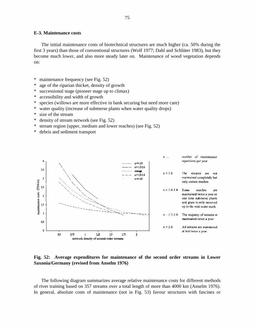
75
E-3. Maintenance costs
The initial maintenance costs of biotechnical structures are much higher (ca. 50% during thefirst 3 years) than those of conventional structures (Wolf 1977; Dahl and Schlüter 1983), but theybecome much lower, and also more steady later on. Maintenance of wood vegetation dependson:
* maintenance frequency (see Fig. 52)* age of the riparian thicket, density of growth* successional stage (pioneer stage up to climax)* accessibility and width of growth* species (willows are more effective in bank securing but need more care)* water quality (increase of submerse plants when water quality drops)* size of the stream* density of stream network (see Fig. 52)* stream region (upper, medium and lower reaches) (see Fig. 52)* debris and sediment transport
Fig. 52: Average expenditures for maintenance of the second order streams in LowerSaxonia/Germany (revised from Anselm 1976)
The following diagram summarizes average relative maintenance costs for different methodsof river training based on 357 streams over a total length of more than 4000 km (Anselm 1976).In general, absolute costs of maintenance (not in Fig. 53) favour structures with fascines or

76
woody vegetation in general over other (including conventional) bank protection methods. Morerecent investigations of some of these aspects support the general rule that, if hydraulic andsafety requirements are met, natural and semi-natural stream management approaches arealtogether cheaper than purely technical river training work.
* “mowing” = mowing and removing of submerse plants* “pest control”* “dredging”* “cut-back thicket” = cutting of trees and bushes back to stock, thinning* “flood damages” = repairing of damages after floods* “others” = transporting material and debris off-site, maintenance of buildings
Fig. 53: Average relative maintenance costs for different bank structures (revised fromAnselm 1976)

77
E.4. Summary
Changes in stream alignment and profile usually have a major impact on construction costs.Costs of the land and groundworks, eventually combined with costs for recreational facilitiesdrive prices up for construction streams. If streams are kept semi-natural, measures againsterosion on the banks and lowering of the stream bed incur the highest costs. The cheapestsolution is to give a stream enough space within set-back dikes. Land use requirements oftenfavour the second cheapest solution: a combination of bed stabilization and longitudinal bankprotection methods. Riprap combined with reed and bush structures are the preferred, andcheapest, heavy-duty construction methods to secure banks when necessary. Costs of plants canbe reduced by building up plantations for the plant material needed. Not all areas need to beseeded, but can be left to natural succession, especially if construction timing follows theripening cycles of naturally distributed seeds.
However, the main point remains to secure only those areas that are endangered by erosion(e.g. the outside bank in bends) with appropriate structures, and not the entire reach. The moreconventional or biotechnical bank securing that is planned, the more expensive the project willbe. Reducing costly structures and starting restoration work in the watersheds (e.g. retarding ofrun-off, erosion control) may free the money necessary to buy up land along streams and providespace for a semi-natural system.

78
F. REFERENCES
ASCE (American Society of Civil Engineers). 1949. Hyrdology handbook. ASCE Manuals ofEngineering Practice No.28. New York, NY.
Aulitzky, H. 1990 MS. Vorläufige Studienblätter zu der Vorlesung Wildbach- undLawienenverbauung. Insitut für Wildbach- und Lawienenverbauung, Universität fürBodenkultur, Vienna, 562p.
Anselm, H. 1976. Analyse der Ausbauverfahren, Schäden und Unterhaltungskosten vonGewässern. Mitteilungen des Instituts für Wasserwirtschaft, Hydrologie undLandwirtschaftlichen Wasserbau, TU Hannover, Report 36:11-191.
Anselm, H. 1984. Verringerung der Ausgaben der Gewässerunterhaltung durch Gewässerpflege.Zeitschrift für Kulturtechnik und Flurbereinigung 25:113-121.
Barker, D.H. 1986. Enhancement of slope stability by vegetation. Ground Engineering19(3):11-15.
Bertram, J.U. 1985. Über den Abfluβ in Trapezgerinnen mit extremer Böschungsrauhigkeit.Leichtwiβ-Institut für Wasserbau der TU Braunschweig, Report 86:1-214.
BMLFW (Bundesministerium für Land- und Forstwirtschaft). 1994. Schutzwasserbau –Gewässerbetreuung – gkologic. Grundlagen für Wasserbauliche Maβnahmen an Flieβgewässern.Vienna.
Bourroughs, E.R. and B.R. Thomas. 1977. Declining root strength in Douglas-fir after felling asa factor in slope stability. Research Paper INT-90, Intermountain Forest and Range ExperimentStation, U.S. Forest Service, Utah, U.S.A.
Burkard, A.M. 1987. Festigkeitsfragen im Grünverbau. Schweizer Ingenieur und Architekt17:461-465.
Chowan, W.L. 1956. Estimating hydraulic roughness coefficients. Agricultural Engineering37:473-475.
Cummins, K.W. and M.J. Klug. 1979. Feeding ecology of stream invertebrates. Ann. Rev. Ecol.Syst. 10:147-172.
Dahl, H.-J. 1984. Zehn Jahre Versuchsstrecke für ingenieurbiologische Ufersicherungsmaβ-nahmen an der Oberaller. Wasser und Boden 3:103-106.
DIN (Deutsche Industrie Norm) 18918. Vegetationstechnik im Landschaftsbau.Ingenieurbiologische Sicherungsbauweisen. Sicherung durch Ansaaten, Bepflanzungen, Bau-weisen mit lebenden und nicht lebenden Stoffen und Bauteilen, kombinierte Bauweisen. Berlin.

79
Donat, M. 1995 MS. Gewässer als Lebensraum. o.ö. Umweltakademie, Linz, 98p.
Donaukraft. 1994. Landschaftsökologische Instandhaltung der Donau. Workshop 22.6.1994,Greifenstein, Proceedings. 78p.
Duhm, J. 1946. Wasserbau, 1. Teil, Der Fluβbau. Verlag G. Fromme, Vienna.
DVWK (Deutscher Verband für Wasserwirtschaft und Kulturbau e.V.). 1984. ÖkologischeAspekte bei Ausbau und Unterhaltung von Flieβgewässern, Merkblätter zur Wasserwirtschaft204, Verlag Paul Parey, Hamburg-Berlin.
DVWK (Deutscher Verband für Wasserwirtschaft und Kulturbau e.V.). 1988. Grundlagen dernaturnahen Regelung bestehender Gewässer. Forbildung 13, Seminar No. 28. Bonn.
DVWK (Deutscher Verband für Wasserwirtschaft und Kulturbau e.V.). 1990. Uferstreifen andFlieβgewässern. Schriften No. 90. 345p.
Ehrengruber, C. 1989. Aspekte des naturnahen Fluβbaus bei Buhnen. Master’s thesis, Universitätfür Bodenkultur, Vienna.
Einstein, H.A. 1934. Der hydraulische und Profilradius. Schweiz. Bauzeitung 103(8):89-91.
Felkel, K. 1960. Gemessene Abflüsse in Gerinnen mit Weidenbewuchs. Report (Mitteilungsblatt)of the Bundesanstalt für Wasserbau, Karlsruhe, 15:34-54.
Frauendorfer, R. 1985. Revitalisierungsmöglichkeiten am Melkfluβ. Master’s thesis, Universitätfur Bodenkultur, Vienna.
Gray, H.G. 1978. Role of woody vegetation in reinforcing soils and stabilizing slopes.Proceedings of the Symposium on Soil Reinforcement and Stabilizing Techniques, Sydney,Australia.
Gray, H.G., and A.T. Leiser. 1982. Biotechnical Slope Protection and Erosion Control. VanNostrand Reinhold Company Inc., New York, NY.
Gray, D.H., and H. Ohashi. 1983. Mechanics of fibre reinforcement in sand. Journal of theGeotechnical Engineering Division, ASCE, 109(3):335-353.
Gray, H.G., and W.F. Megaham. 1981. Forest Vegetation Removal and Slope Stability in theIdaho Batholith. Intermountain Forest and Range Experiment Station, Ogden, Utah, ResearchPaper INT-271.
Greenway, D.R. 1987. Vegetation and slope stability. Pages 187-230 in M.G. Anderson and K.S.Richards, editors. Slope stability. Wiley Publishers, Edmonton, Alberta.
80
Horton, R.E. 1933. Separate Roughness Coefficients for Channel Bottom and Sides. EngineeringNews-Record 22: 652-653.
Kern, K. 1994. Grundlagen naturnaher Flieβgewässergestaltung. GeomorphologischeEntwicklung von Flieβgewässern. Springer Verlag, Berlin.
Lange, G. and K. Lecher. 1993. Gewässerregelung und Gewässerpflege. Naturnaher Ausbau undUnterhaltung von Flieβgewässern. Paul Parey Verlag, Hamburg, Berlin.
Lindner, K. 1982 Der Strömungswiderstand von Pfanzenbestanden. Leichtweiβ-Institut fürWasserbau der TU Braunschweig, Report No. 75:1-235.
Lowe, S. 1992. Fish habitat enhancement structures. Typical structure designs. AlbertaEngironmental Protection, Water Resources Management Services, Technical Services andMonitoring Division, River Engineering Branch, Edmonton, Alberta. 32p.
Niemeyer-Lüllwitz, A., D. Popp, J.A. Winkler and H. Zucchi. 1988. Rettet die Bäche. Natur &Umwelt Verlags GmbH, München.
Pasche, E. 1984. Turbulenzmechanismen in naturnahen Flieβgewässern und die Möglichkeitenihrer mathematischen Erfassung. PhD thesis, Rheinisch-Westfählische Technische HochschuleAachen.
Pregl, O. 1986. Handbuch der Geotechnik. Böschungen, volume 10. Universität für Bodenkultur,Vienna. 362p.
Rickert, K. 1986. Der Einfluβ von Gehölz auf die Lichtverhältnisse und das Abfluβverhalten inFlieβgewässern. Institut für Wasserwirtschaft, Hydrologie und landwirtschaftlichen Wasserbauder Universität Hannover, Report No. 61: 1-216.
Rickson, R.J. and R.P.C. Morgan. 1988. Approaches to modelling the effects of vegetation onsoil erosion. Proceedings of the EEC Workshop on Erosion Assessment for the EEC : Methodsand Models, Brussels, Belgium, 237-253.
Rouve, G. 1987. Hydraulische Probleme beim naturnahen Gewässerausbau. Forschungsberichtder Deutschen Forschungsgemeinschaft. VCH-Verlag, Weinheim.
Saupe, G. 1992. Wirkung von Konturgrasstreifen zur Erosionsbekämpfung unterPraxisbedingungen. Zeitschrift für Kulturtechnik und Landentwicklung 33, 150-162.
Scheuerlein, H. 1968. Der Rauhgerinneabfluβ. Versuchsanstalt für Wasserbau, TechnischeHochschule Munchen, Report 14: 1-124.
Schiechtl, H.M. 1973. Sicherungsabeiten im Landschaftsbau. Verlag G.D.W. Callwey, Munich.

81
Schiechtl, H.M. 1982. Pflanzenausfall, Pflanzenbeschaffung, Pflege, Kosten. Ökologie vonFlieβgewässern. Institut für Landschaftswasserbau, TU Wien, Report No. 3:189-216.
Schiechtl, H.M., und R. Stern 1992. Handbuch für naturnahen Erdbau. Eine Anleitung füringenieurbiologische Bauweisen. Österr. Agrarverlag, Vienna.
Schiechtl, H.M., und R. Stern. 1994. Handbuch für naturnahen Wasserbau. Eine Anleitung füringenieurbiologische Bauweisen. Österr. Agrarverlag, Vienna.
Schleicher, F. 1955. Taschenbuch für Bauingenieure. volume2, Springer Verlag, Berlin.
Schwab, J.W. 1991. Forest road deactivation and hillslope revegetation. Pages 167-205 in BCMinistry of Forests. A guide for management of landslide-prone terrain in the Pacific Northwest.Land Management Handbook No. 18, Victoria, B.C.
Tönsmann, F. 1983. Kostenuntersuchungen verschiedener Ausbaukonzepte im naturnahenWasserbau. 7. DVWK-Fortbildungslehrgang Gewässerausbau – Gerinnestabilität. Darmstadt.
Tsukamoto, Y. and O. Kusakabe. 1984. Vegetation influences on debris slope occurances onsteep slopes in Japan. Proceedings of the Symposium on the Effect of Forest Land Use onErosion and Slope Stability, Hawaii, U.S.A.
USSCS (U.S. Soil Conservation Service). 1970. Irrigation Requirements. USDA TechnicalRelease No.21, U.S. Government Printing Office, Washington, D.C.
USSCS (U.S. Soil Conservation Service). 1972. Hydrology. National Engineering Handbook.USDA, Section 4, U.S. Government Printing Office, Washington D.C.
USGS (U.S. Geological Survey). 1967. Roughness Characteristics of Natural Channels.Geological Survey Water-Supplementary Paper 1849. U.S. Government Printing Office,Washington, D.C.
Waltl, A. 1948. Der natürliche Wasserbau an Flüssen und Bächen. Publication Series of theProvincial Government of Upper Austria, Linz, No. 3:1-144.
Wesche, T.A. 1985. Stream channel modifications and reclamations Structures to enhance fishhabitat. in J. Gore, editor. The restoration of rivers and streams. Butterworth Publishers,Stoneham, MA.
Wildermuth, H. 1978. Natur als Aufgabe. Schweizerischer Bund für Naturschutz (Eigenverlag).Basel.
Wolf, H. 1977. Naturnaher Gewässerausbau – Erfahrungen und Beispiele aus Baden-Württemberg. Veröffentlichungen Naturschutz und Landschaftspflege baden-Württemberg No.46.

82
Appendix
“COMPOUND STRENGTH” OF ROOTED SOIL
The soil stabilization effect of plant roots is based on two components: (1) by frictionbetween the soil particles that transfer shear stresses from the soil to the root reinforcementsystem, and (2) by soil arches that build up between cylindrical soil units that are reinforced byroots (root stock-soil elements) and stabilize areas that are not rooted. Shear increase in rootedsoil is based on the model of a “compound strength” of a material that consists of fibres ofrelatively high strength and adhesion to a matrix of lower tensile strength. Most geotechnicalmodels express the increase in shear strength of rooted soil as an increase in cohesion exclusivelybased on the anchoring effect of plant roots. Rarely do such models take into account an increaseof the angle of inner friction due to biologically changed soil properties.
Biotechnical reinforcement occurs in relatively shallow soil layers. The rooting depths ofherbaceous plants is less than 0.5 m, that of trees and bushes less than 3-5 m. Therefore, normalstress is small and an increase in surcharge (surface load of the vegetative cover and the storedwater) is almost negligible. In this range of normal stress the Coulomb approximation of theshear curve differs considerably from the Mohr envelope curve, and the angle of internal frictionchanges quickly (Fig. 55).
Fig. 55: Mohr and Coulomb shear curve

83
The Mohr curve should therefore be used for quantifications of plant root effects on soilshear resistance, since it is more accurate than the Coulomb curve in the range of small normalstresses. There are two ways to describe the Mohr curve: (1) approximations (curve or polygon)that best fits with the test results, or (2) analytical approaches such as the following equation(Pregl 1986):
φ = a + b*log(e0/e) + c*log(σ/σb) (Equ. 1)
φ … shear angle = angle between x-axis and the line from point zero of the coordinate systemto the point on the shear curve. It is not the angle of internal friction (rad)
e … present void ratioe0 … initial void ratio = reference void ratioσ … present normal stress (kN.m-2)σb … reference normal stress (freely chosen: 10 kN.m-2)a,b,c … material specific constants
For soils without true cohesion (no particle cementation by pore water pressure) “a” is zero,for rock material “a” is greater than zero. The shear strength τ at a certain normal stress σ iscalculated as:
tan φ = τ / σ (Equ. 2)
τ = σ *tan φ (Equ. 3)
The increase in shear strength by roots “∆τ” is the plant- and soil-specific verticaldisplacement of the Mohr curve (Fig. 56).
Fig. 56: Shear curves with and without plant root reinforcement

84
“∆τ” is not constant, but decreases with depth, and is zero in soil horizons without rootreinforcement. An increase in cohesion due to soil suction under unsaturated soil waterconditions is only temporary and should not be considered. The modified equation for shearresistance of a soil with root reinforcement is:
τ = ∆τ + σ *tan φ (Equ. 4)
τ … shear strength (kN.m-2)∆τ … root reinforcement effect (kN.m-2)σ … normal stress (kN.m-2)φ … shear angle (°)
φ is the shear angle, and not the angle of internal friction Φ(See Fig. 57)
Fig. 57: Shear angle and angle of inner friction
“∆τ” depends on:
- the tensile strength of the roots- the soil material- the friction between root surface and soil material
To obtain the final Mohr curve for rooted soil, “∆τ” has to be calculated for a several depths(normal stresses) with the prevailing angle of internal friction and root ratio.

85
Theoretical model for shear strength increases due to plant roots
Roots that contribute to an increase of shear strength must cross the sliding plan. Bydisplacement of the soil within the shear zone, tensile stress is mobilized in the roots. The rootsact like anchors. Root stress components tangential to the sliding plane are shear forces. Stresscomponents in a right angle to the shear surface increase the normal stress in the sliding plane. Itis assumed that the roots are anchored sufficiently on both sides of the sliding plane so thatfailure is caused by rupture of the root and not by pulling them out from the soil. Furtherassumptions are: (1) the root is in a right angle to the sliding plane before shearing, (2) the tensilestrength is completey mobilized, (3) the roots do not change the angle of internal friction of thesoil. Under these conditions, the increase in shear strength (as an increase of cohesion c) is:
∆τr = tr*(cos θ *tan Φ + sin θ) (Equ. 5)
tr = Tr*(Ar/A) = ∑ ((Tr,i*ni*ai)/A) (Equ. 6)
tr … tensile strength of the roots per unit area of the sliding plane (kN.m-2)Tr … average tensile strength of the roots (kN.m-2)Ar/A .. area ratio occupied by roots (m2.m-2)Tr,i … average tensile strength of the roots of the diameter class i (kN.m-2)ni … average number of roots of the diameter class i per unit areaai … average cross section area of roots of the diameter class i (m2)A … cross section area (m2)θ … angle of shear distortion (°)
The distortion angle θ depends on the thickness of the shear zone and the shear displacementwhen approaching the maximum shear strength (θ usually between 40° to 70°). As Φ is between25° and 40°, the term (cos θ *tan Φ + sin θ) is in the range from 1.0 to 1.3 (most probably 1.15).
∆τr = 1.15 * tr (Equ. 7)
To be able to attribute the shear failure to root rupture, the minimum anchoring length of theroots on both sides of the sliding plane has to be
Lmin>(Tr*dr)/(2*τ'r) (Equ. 8)
Lmin … minimum anchoring length (m)Tr … tensile strength of the roots (kN)dr … diameter of the roots (m)τ'r … shear strength between root and surrounding soil (kN.m-2)
= maximum bond stress or pull-out resistance between root and soil.

86
This simple estimation bases the increase in shear strength on the average tensile strength Tr
of the roots and the area ration Ar/A. To be on the safe side, despite of assumptions such asconstant root properties or a full mobilization of the shear strength of different root diameters atthe same extension, the tensile strength is usually assumed sufficiently low. While thecontribution of roots to shear strength increases should vary with their angle to the shear plane,experimental results have shown that purely random positioned fibres produce approximately thesame increase in shear strength as fibres perpendicular to the shear plane do (Gray and Ohashi,1983). Therefore, the simple, theoretical model based on perpendicular roots (fibres) issufficiently accurate.


![Cyanobacteria (Blue-green Algae) in Our Waters · Manual of water supply practices, 1st ed. [M57]. Bentrup, G., and J.C. Hoag. 1998. The practical streambank bioengineering guide:](https://img.pdfslide.net/doc/110x75/5ec7a2f57967e92432075426/cyanobacteria-blue-green-algae-in-our-waters-manual-of-water-supply-practices.jpg)