Embed Size (px)
Citation preview

Biological Safety Cabinet
Class II A2
BSC-11IIA2-X
BSC-13IIA2-X
BSC-15IIA2-X
USER MANUAL
Hagavish st. Israel 58817 Tel: 972 3 5595252, Fax: 972 3 5594529 [email protected]
MRC.10.16
Thank you very much for purchasing our class II A2 biological safety
cabinet.
Please read the “Operating Instructions” and “Warranty” before
operating this unit to assure proper operation. After reading these
documents, be sure to store them securely together with the “Warranty”
at a hand place for future reference.
Warning: Before operating the unit, be sure to read carefully and
fully understand important warnings in the operating instructions.

2
CONTENT
1. Unpacking, Installation, Debugging ..................................................................................................3
1.1 Unpacking ........................................................................................................................................3
1.2 Accessories checking .......................................................................................................................6
1.3 Installation conditions and using environment ................................................................................7
1.4 Installation........................................................................................................................................8
1.5 Check after installation finished ....................................................................................................13
2. User Instructions ..............................................................................................................................14
2.1 Functions........................................................................................................................................14
2.2 Product structure ............................................................................................................................17
2.3 Control panel..................................................................................................................................22
2.4 Remote Control &Foot switch .......................................................................................................24
2.5 Instructions for Operation ..............................................................................................................25
2.6 Daily maintenance .........................................................................................................................27
2.7 Methods and procedures for disinfection ......................................................................................29
2.8 Replacement parts list ...................................................................................................................30
2.9 Wiring diagram ..............................................................................................................................33
3. Trouble shooting and Labels............................................................................................................35
3.1 Common faults & solution.............................................................................................................35
3.2 Label Description...........................................................................................................................40
4. Warranty ..........................................................................................................................................43

3
1. Unpacking, Installation, Debugging Please firstly check if packing box is in good condition. If the packing box is damaged, please take
photos.
1.1 Unpacking
Choose the proper unpacking method according to the actual situation.
For wooden box:
1) Method 1 Necessary tools for unpacking: Electric drill with hexagon dead M8
Picture 1
2) Method 2 Use M8 Wrench to unpack

4
Picture 2
Rapid unpacking diagram (Picture 3). Disassemble the screws shown in the below Picture, then
move the wooden pieces to right and left.
Picture 3

5
For carton box:
Using ordinary scissors to cut packing tape, take off the package cover, then move up the paper box
body.
Picture 4

6
1.2 Accessories checking
Refer to the packing list and check the accessories.
Packing list (BSC‐11/13/15IIA2‐X) Items Model Position Quantity
Main Body Wooden box 1unit
UV Lamp (T6 30W) BSC‐11IIA2‐X
BSC‐13IIA2‐X 1pc
UV Lamp (T6 40W) BSC‐15IIA2‐X
Top or back of main body
1pc
Base Stand Placed in two carton boxe 1set
BSC‐11IIA2‐X
BSC‐13IIA2‐X
1pc Fuse (10A)
BSC‐15IIA2‐X 3pcs
Fuse (5A) 1pc
Remote control (including battery) 1pc
Keys 2pc
User manual 1pc
Test report 1pc
Quality certification card
Placed in a transparent
plastic bag
1pc
Power cord 1pc
Foot switch 1pc
Drain Valve 1set
Stainless steel hex cylinder head bolt M10×55 3pcs
Stainless steel flat washer10 3pcs
Stainless steel spring washer 10 3pcs
Inner hexagon wrench 1pc
Big rubber gasket 1pc
Small rubber gasket 1pc
Front window tubular motor control rod 1pc
Buckle stopper (white)
Placed in the carton
accessory box
7pcs

7
1 .3 Installation conditions and using environment
To avoid disturbances to the safety cabinet and its operator, follow the following guidelines, while
determining a suitable location for the cabinet:
a. The distance from the plane of the aperture to any circulation space should be at least 1000 mm,
so as to preserve a zone undisturbed by anyone other than the operator.
b. Biological safety cabinets should be placed in a position where there should be no opposing wall
(or other obstruction likely to affect the airflow) within 2000 mm of the front aperture.
c. Safety cabinets should not be installed in positions where they are likely to be affected by other
items or equipment. In particular the distance to the aperture of an opposing safety cabinet, fume
cupboard, or the edge of a local exhaust ventilation outlet should not be less than 3000 mm.
d. Any room air supply diffuser should not be within 1500 mm of the front aperture.
e. Doorways should not be within 1500 mm of the aperture or within 1000 mm of the side of the safety cabinet.
f. The position of a safety cabinet should satisfy the spatial requirements (e.g. vision, lighting and convenience of access) of the operator and personnel working nearby. When a cabinet is installed on a bench top, the leading edge should be flush with or slightly overhanging the edge of the bench top.
Working environment:
(1) Only is suitable for indoor;
(2) Ambient temperature: 15OC~35OC;
(3) Relative Humidity: ≤75%;
(4) Atmospheric pressure range: 70 kPa~106 kPa;
(5) Electrical parameters: Consistent with the rated voltage of the biosafety cabinet (See 2.1.5
technical parameter performance index);
(6) Power supply need to be grounded; (Judging method: testing the fire wire and the zero line of the
power supply with multimeter, the fire wire to ground voltage should be grid voltage and the zero
line to ground voltage should be 0, otherwise the power supply ground is bad).
(7) Test the voltage stability before using, if the voltage is unstable, should use the voltage regulator,
otherwise the control panel and transformer may be easily damaged.

8
1.4 Installation
a. Remove all the package materials;
b. Inspect the surface of main body to make sure whether there is scratch, deformation or
uncorrelated things;
c. Move the whole device to the final installation location;
The base stand will be packed at back of main body, please take it out before installation. DO NOT
INVERT, DISASSEMBLE OR TITILE THE CABINET during transportation.
d. The base stand assembly
Referring to Picture 5 assemble the base stand.
Note: The base mounting bolts are fixed to the base stand. When install the base stand, except the 4
bolts marked with red circle in Picture 5, please remove the other bolts and install.
Remove the M10×55 Hexagon socket head screws, Buckle plug, M10 Stainless steel flat washer, M10
Stainless steel spring washer, M10 Stainless steel cap nuts, referring to Picture 5 assembled base,
firmly fastening requirements.

9
e. Connect base stand and main body
Refer to Picture 6, 7 to connect base stand and main body.
Picture 6
Aligned the mounting holes on the bottom of the cabinet side with the locating bolts, slow down the
cabinet on the mounting base.

10
Picture 7
Take out the M10*55 Hexagon socket head screws, Flat washer 10, Spring washer 10 from the
accessory box, and fasten tightly according to Picture 7.
f. Installation of Drain valve

11
Picture 1
1. Drain valve connecter
2. Shim (Inner diameter*outer diameter*thicknessΦ20*Φ28*2mm)
3. Safety cabinet bottom installation holes
4. Ball coupling fastening nut
5. Rubber gasket (Inner diameter*outer diameter*thicknessΦ13*Φ19*2mm)
6. Drain valve
Take out drain valve coupling, shim, Ball nut, Rubber gasket, Drain valve, assembling from up to
down as Picture 8 illustrated.
g. Adjustment of Footmaster Caster
Picture 2
Clockwise rotate caster’ red part to low down the base feet and the height of the cabinet. Low down
all four casters can move the cabinet position. Counterclockwise rotate casters’ red part can rise the
base leg and height of cabinet. Raise all four casters can at same time can fix the cabinet. Adjust the
four Foot -masters makes the cabinet stable.

12
h. Foot Switch
Picture 3
Install Foot Switch as Picture 10. It’s socket is at the left top, connect the plug.
i. Installation of Water and Gas Tap(Optional)
Picture 4
1. Fastening Nut
2. Stainless Steel Water and Gas Taps
Take out fastening nuts , water and gas taps, installing as Picture 11.
13
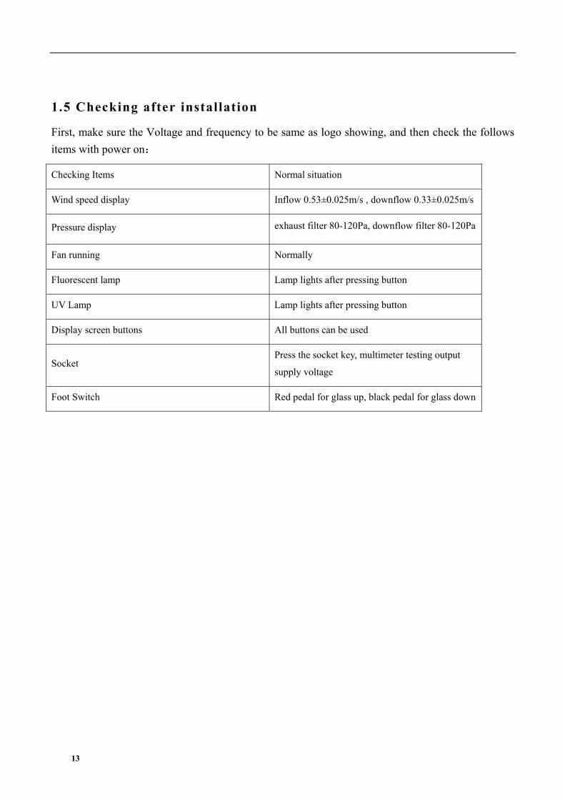
1.5 Checking after installation
First, make sure the Voltage and frequency to be same as logo showing, and then check the follows
items with power on:
Checking Items Normal situation
Wind speed display Inflow 0.53±0.025m/s , downflow 0.33±0.025m/s
Pressure display exhaust filter 80-120Pa, downflow filter 80-120Pa
Fan running Normally
Fluorescent lamp Lamp lights after pressing button
UV Lamp Lamp lights after pressing button
Display screen buttons All buttons can be used
Socket Press the socket key, multimeter testing output
supply voltage
Foot Switch Red pedal for glass up, black pedal for glass down

14
2. User Instructions2.1 Functions
2.1.1 Product Concept
This products belong to Class II A2 biological safety cabinet which fully meet the requirement of US
standard ANSI/NSF49:2002, European standard EN12469:2000, biological safety cabinet is a kind
of negative pressure filtration system for protecting operator, the laboratory environment and work
materials, the front opening which air flow inward have protection function for operator, the filtered
laminar flow generated by vertical HEPA can protect work materials, what’s more, the polluted air
flow become pure after processed by HEPA(ULPA) filter. When it’s used in microbiology
experiment environment filled with volatile or toxic chemical and radionuclide, suitable exhaust
hood in function have to be linked.
2.1.2 Application Range
Biological Safety Cabinet is necessary equipment in the laboratory in the search of microbiology,
biomedical, DNA recombinant, animal experiment, and biological products, especially in the
occasion that operator need to adopt protective measure, such as medical and health, pharmacy,
medical research. Our equipment provides a safety working environment which don’t have bacterial
and dust in the process of bacterial culture.
2.1.3 Working theory/Air flow pattern and protected area
Picture 5
2.1.4 Protected objects
Biological safety cabinets (BSCs) are designed to protect the operator, the laboratory environment

15
and work materials from exposure to infectious aerosols and splashes that may be generated when
manipulating materials containing infectious agents, such as primary cultures, stocks and diagnostic
specimens.
2.1.5 TECHNICAL PARAMETERS
Model
Parameters BSC-11IIA2-X BSC-13IIA2-X BSC-15IIA2-X
Product Standard Meet US standard ANSI/NSF49:2002, European standard EN12469:2000
Standard
Power Supply AC 220V±10% 110V±10%
Frequency 50 Hz 60Hz
External Size(W*D*H) 1100×750×2250 mm 1300×750×2250 mm 1500×750×2250 mm
Working Zone
Size(W*D*H) 940×600×660 mm 1150×600×660 mm 1350×600×660 mm
Consumption 760W 800W 900W
Total Airflow Volume 360m3/h 440m3/h 500m3/h
UV Lamp Consumption 30W 30W 40W
Fluorescent lamp
Consumption 21W*2 21W*2 28W*2
Downflow Velocity 0.33±0.025m/s
Inflow Velocity 0.53±0.025m/s
HEAP Filter 99.999%(Diameter: 0.3μm)
Noise EN12469 ≤58dB / NSF49≤61dB
Notes: (1) Electric consumption power including power which operation area needs to load (Loading
no more than 500W)
(2) Our company has right for changing the products, if we need to change and re-design,
please forgive us for not notifying you.
16
2.1.6 Performance Index
1) Biological safety functions
Personnel protection, microbial colony count ≤5CFU;
Sample protection, microbial colony count ≤5CFU;
Cross contamination protection, microbial colony count ≤2CFU.
2) Leak-proof Cabinet
If cabinet pressurized to 500Pa, the pressure should be no less than 450 Pa after 30 min.
3) Integrity of HEPA Filter
Scan and detect the HEPA filter, the leakage rate at any point should not be >0.01%.
4) Vibration amplitude
The net vibration amplitude between frequency 10Hz and 10KHz is no more than 5μm(rms).
5) Illumination
The average illumination is no less than 650 lux, max illumination is no less than 1000lux.
6) Mechanical performance
Structure design is reasonable, high quality materials are adopted for the cabinet.
It can resist shape global deformation caused by external force.
The working surface will not occur permanent deformation when weight put reaching 23kg.
7) Electrical properties
The voltage increases to 1390V(AC) in 5s and keep for another 5s without breakdown.
Grounding resistance ≤0.1Ω

17
2.2 Product structure
2.2.1 Structural composition of BSC-11IIA2-X
Picture 6
1. Footmaster Caster
2. Fluorescent Lamp
3. Nameplate
4. Tube motor
5. Fuse socket
6. General power fuse socket
7. Power socket
8. UV lamp
9. Control panel
10. Power supply lock
11. Water-proof socket
12. Front window
13. Inflow grid

18
2.2.2 Structural composition of BSC-13IIA2-X
Picture 7
1. Footmaster Caster
2. Fluorescent Lamp
3. Nameplate
4. Tube motor
5. Fuse socket
6. General power fuse socket
7. Power socket
8. UV lamp
9. Control panel
10. Power supply lock
11. Water-proof socket
12. Front window
13. Inflow grid

19
2.2.3 Structural composition of BSC-15IIA2-X
Picture 15
1. Footmaster Caster
2. Nameplate
3. Power socket
4. General power fuse socket
5. Fuse socket
6. Blower fuse tube socket
7. Tube motor
8. UV lamp
9. Power supply lock
10. Fluorescent Lamp
11. Water-proof socket
12. Control panel
13. Front window
14. Inflow grid
2.2.4 Structure introduction
1) Driving System of Front Window
Driving system consists of tube motor, front window, hauling sash and position switch.
2) Air Filtration System

20
Air Filtration System is the most important system of BSC. It consists of blower, supply filter and
exhaust filter. The function of Air Filtration System is transferring filtered air to work area, ensure
the down flow velocity, and keep Class 100 cleanness of work area.
3) UV Light
UV lamp is inside work area. So UV lamp can well sterilize all space of work area. Emission of
253.7 nanometers can ensure most efficient decontamination.
4) Fluorescent Light
The BSC is equipped with straight tube type energy-saving fluorescent lamp. It can make sure
average illumination inside work area which meets standard requirements.
5) Air pipe
Air pipe is the ventage of differential pressure sensor.
The air pipe should not be blocked and please do not hang anything on the pipes,
otherwise it will effect wind speed and pressure.
6) Power lock
When the power cord is connected to main power, switch the key for power lock, then the equipment
is powered on.
7) Water proof Socket
Waterproof Sockets are located on the right side of the work area, which can be controlled by
SOCKET button.
(1) Please make sure the total load of sockets should be ≤ 500W;
(2) Fuse protector:(see Picture 27)

21
The equipment is equipped with main power fuse, waterproof socket fuse and fan fuse (only for
BSC-15IIA2-X). They are located near the power cord’s outlet. Fuse label is corresponding to the
relevant specifications. Please refer to 3.2.
8) LCD Display(Liquid Crystal Display)
Picture 8
Large LCD display indicates detailed key parameters, it is real-time display to reflect the equipment
working condition, such as effective working state of the filter, which is more intuitive. (Please refer
to 2.3)
9) Control of Front Window
Front window is motorized. It could be controlled in 3 ways including by remote control, foot switch
and control panel.
10) Structure
a) Biological Safety Cabinet’s both sides and back area are negative pressure air channel. And
the negative pressure keeps work area away from contamination.
b) Cabinet body is built of 1.2mm cold-rolled steel with anti-powder coating. Strong and steady.
c) Work area is fully made of 304 stainless steel which looks beautiful and with corrosion
resistance performance.
d) Base stand is made of cold-rolled steel with anti-powder coating.
e) Soft touch type control panel, easy to handle and beautiful appearance.

22
2.3 Control panel
Picture 9

23
a) LCD Screen
The working status of the equipment and operation can be seen on the LCD screen.
b) Soft touch button.
BSC’s main functions could be executed by touch-buttons. User can operate the BSC either by
pressing the buttons on control panel or using the remote control. There are totally 8 common button
on control panel.
: The power button
: To control fluorescent lamp
: To control UV lamp.(It works only after front window fully closed.)
: To control blower working status. (It will not work when front window is fully
closed.)
: To control socket power status.
: Press MUTE button to stop voice prompt
: Press UP button, glass window will raise.
: Press Down button, glass window will fall down.
Clock Adjustment:
Turn the power key, so machine is in standby state.
Press the light button, and then press the power button for 5 seconds. Then you see the state of clock
adjustment after a buzzer alarm.
Firstly, minute position is flashing, press UP and DOWN to adjust to present time. Then press the
MUTE button switching to hour position and adjust to present time. After that, press the light button
first, and press the power button for about 5 seconds. Data will be saved after a buzzer alarm.

24
2.4 Remote Control &Foot switch
2.4.1 Remote control
It is inconvenient for the users to operate from a distance. Small & light remote control is flexibly to
be used to control all the functions of the cabinet in a distance ≤6m, 30° range. The operator can
even carry it with themselves during experiment for convenience.
This remote control adopt specific chip which is featured with good anti-jamming performance,
longer control distance and high control precision.
Picture 10
Buttons of Remote Control:
1. Power (POWER)
2. Reservation Time (SUB)
3. Timer (INSTALL TIMER)
4. Confirm (CONFIRM)
5. Cancel (CANCEL)
6. Turn up (+)
7. Turn down (-)
8. Fan (FAN)
9. UV (UV)
10. Illumination (LIGHT)
11. Socket (SOCKET)
12. Mute (MUTE)
13. Front window up (UP)
14. Front window down (DOWN)
Remote Control
A. Reservation Time (SUB)
a. Connect power, open power lock, and press the reservation timing button (SUB);
b. Adjust the time (minutes) by “+” or “-” button. Press the confirmation button (CONFIRM) to
confirm; and then adjust other minutes and hours position data in the same way;
c. After the time is confirmed, the corresponding display lamp lights by selecting the function
buttons (such as UV);

25
d. Press the POWER button again, the reservation function starts. Reserved time starts count
down. The corresponding setting function starts when the time counts down to zero.
B. Timer (INSTALL TIMER)
a. Connect power, open power lock, press button (POWER), the corresponding display lamp
lights by selecting the function buttons (such as UV);
b. Press button (INSTALL TIMER), adjust the time (minutes) by “+” or “-” button. Press button
(CONFIRM) to confirm; and then adjust other minutes and hours position data in the same
way;
c. After the time is confirmed, the Timer function starts. When the time counts down to zero, all
the functions will be off, the cabinet will be in standby mode.
C. Application of Reservation Time
Biological safety cabinet is equipped with special UV lamp. When turning on or turning off the
cabinet, sterilization time of UV lamp should be at least 30 minutes. In order to save the waiting time
of turning on or turning off the cabinet, we develop reservation time function. It realizes function of
automatic turning on or turning off the cabinet after the sterilization finished. Reservation time
setting range is from 0 to 99 hours and 59 minutes. This function helps operators to save time and
improve efficiency.
2.4.2 The use of foot switch
Picture 11
Press the left red switch by foot, front window goes up, press the right black switch, front window
goes down.
2.5 Instructions for Operation
2.5.1 Normal Operation Notice
(1) Make sure input voltage is correct and stable. The rated load of main power socket
should be higher than cabinet consumption. Plug must be well grounded.
(2) In order to avoid air turbulence, the operator should slightly move his arms during
experiment. Hands should stay inside the working area at least 1 minute before
operating. In order to decrease the times of arms moving into and out of the working
area, prepare all the necessary items inside the cabinet before starting experiment;

26
(3) Moving principles of different samples inside cabinet: When two or more samples need
to be moved, be sure that low-polluting samples move to high-polluting samples.
Movement of items should also follow the principles of slow-moving.
(4) Samples placed in parallel: Samples should be placed in the cabinet parallel to avoid
cross-contamination between samples and blocking back air grille.
(5) In order to avoid samples being sucked into the negative passage or the blower, do not
place soft and slight samples (for example: soft tissue) on the surface during
experiment;
(6) The weight of items placed in the cabinet should be no more than 23Kg/25×25cm2;
(7) Avoid vibration: avoid using vibration equipment (eg centrifuges, vortex oscillator, etc.)
inside the cabinet. Vibration would cause lower cleanliness of operating area and affect
operator protection.
(8) No flame: No flame is allowed inside the cabinet. Using of fire will lead to airflow
disorder, and filter damage. If sterilization is required during the experiment, infrared
sterilizer is highly recommended.
(9) HEPA filter life: With the usage time increasing, dust and bacteria accumulate inside
HEPA filter. Filter Resistance is getting bigger, when it reaches the maximum point,
there will be audible and visual alarm. Please replace new HEPA filter, otherwise it will
affect the safety performance of the equipment. The used filter should be processed as
medical waste.
(10) There is a negative passage surrounding the work area, which is sealed strictly in the
factory. The operator is not allowed to remove or loose screws of those parts. If
necessary, please contact service personal.
(11) Front Grille is used for air intake and drain. Do not block it, otherwise it will affect
airflow. Armrest is recommended to solve this problem and reducing the operator's
wrist fatigue.
(12) Long-term use of biological safety cabinets will inevitably cause pollution (e.g. HEPA
filters, corner cabinets, etc.). In order to sterilize thoroughly every 500 hours, formalin
(formaldehyde) fumigation sterilizer is recommended. After sterilization, neutralize
formaldehyde gas with ammonium hydrogen carbonate. Make sure no sterilization gas
escapes during the whole process.
(13) The maximum storage period is one year. If the period is more than one year,
performance test should be done .

27
Serious declaration: we will take no responsibility for risks caused by improper
operation and man-made damages!
2.5.2 Operation Process
a. Connect the same power reply, as required of equipment
b. Open the power lock, LCD display lights up and alarm rings at the same time, then the machine
enters to standby status. Waiting for the operator to input button to use it.
c. Press POWER button, then the following functions are available: Fluorescent lamp. UV lamp, Fan,
Mute, Sockets, Front window up and down, Reservation timing
When front window is closed and fluorescent light is off, then press the UV button to
select the sterilization function.
d. Before doing experiment, please sterilize the cabinet for more than 30 minutes by UV lamp.
(1) For safety of eyes and skin, people should leave room during the UV sterilization.
(2)UV lamp intensity should be tested regularly. If there is no test conditions, it should be
replace when the UV timer on the display indicate the working time reaches to 1000 hours.
e. Please move the front window at 200mm height from the work table, turn on the fan, make sure
the experiment should be started after fan working for at least half an hour.
For operating safety, please put testing materials inside the cabinet in advance, and keep
the front window at 200mm height from the work table during operation.
After finishing the experiment, please move the front window down to the bottom, and make sure to
sterilize the cabinet by UV lamp for 30 minutes before turning off the cabinet.
2.6. Dai ly maintenance
Because the operating time will directly affect the judgment of maintenance needs, we recommend
the user keep a detailed record of operating time for reference.
When doing maintenance, please pay attention to cut off the power, so as to avoid electric
shock!
2.6.1 Preparations before maintenance
Soap, hot water or warm water, a soft cotton cloth, dry cloth or towel, medical alcohol or other

28
disinfectants, 100 dilution of household bleach, abrasive household cleaners, sterile water
2.6.2 Clean the cabinet surface
1) Clean the operating area surface
Wipe the entire surface with a soft cotton cloth or towel soaked with concentrated liquid soap, then
wipe up the soap with another cotton cloth or towel soaked with clean hot or warm water, and then
wipe the surface with a dry cotton cloth or towel rapidly.
For the contaminated or dirty work surface or sump., use 70% medical alcohol or other disinfectant
to wipe.
Disinfectants used for wiping should not damage 304 stainless steel.
2) Clean the external surface and front window.
Use soft cotton cloth or towel to wipe the surface with non-abrasive household cleanser.
2.6.3 Overall maintenance period
We suggest comprehensive maintenance period is one year or 1000 working hours.
2.6.4 Maintenance methods
a. Disinfect and clean operating area;
b. Clean the external surface and front window around the operating area;
c. Check the various functions of equipment;
d. Record this maintenance result
1) Monthly maintenance
a. Clean the the external surface and front window.
b. Wipe the working table, inner wall surface of operating area (excluding the wind distributing grid
of operating area) and the inner surface of glass door with 70﹪ medical alcohol or household
bleach diluted 1:100 (i.e, 0.05% sodium hypochlorite). Then wipe again with sterile water in
order to eliminate the rest chlorine.
c. Check the various functions of equipment;
d. Record this maintenance result;
2) Annual maintenance
a. Check the two conveyor belts of front window drive unit, and ensure that their tightness is
coincident.
b. Check the UV lamp and fluorescent lamps.
c. Apply for testing the overall performance of cabinet on an annual basis to ensure the

29
performance safety. User is responsible for testing costs.
d. Record this maintenance result.
2.6.5 Storage conditions
Safety cabinet should be stored in a relative humidity no more than 75%, the temperature is below
40, in the warehouse with good ventilation performance, no acid, no alkali and no other corrosive
gases, storage period shall not exceed one year, safety cabinet for more than a year needs to
unpacked and checked. Only the tested and qualified safety cabinet can be sold.
2.7 Methods and procedures for disinfection
Details in the After-sale service manual
Disinfection is necessary when any contaminated part of the biosafety cabinet needed for routine
maintenance, replacement filters, and performance testing, etc. Before doing certification test and gas
sterilization, all internal working surface and the exposed outer surface should be disinfected with a
suitable disinfectant.

30
2.8 Replacement parts l ist
BSC-11IIA2-X replacement parts list
Number Name Specification
AAQ01 Fuse 10A
AAQ02 Fuse 5A
AAQ03 Lamp holder T8 LG13-01A
AAQ04 Lamp holder T5 LG05-01A
AAQ05 UV Lamp T6 30W
AAQ06 Fluorescent Lamp T5 21W
AAQ07 UV lamp ballast 1*TL8-30W
AAQ08 Fluorescent lamp ballasts 2*TL5-28W
AAQ09 Upper filter (Exhaust filter) 800*420*69mm
AAQ10 Lower filter (Supply filter) 925*470*69mm
AAQ11 Fan FS133Q
AAQ12 Control panel
LCD control board (strong circuit board,
weak circuit board, display screen)
AAQ13 Remote control (with battery)
AAQ14 Key selection button YJ139(LA38, LA39)
AAQ15 Glass 1034*730*6.38mm
AAQ16 Foot switch

31
BSC-13IIA2-X Replacement parts list
No. Designation Standard
AAP01 Fuse 10A
AAP02 Fuse 5A
AAP03 lamp holder T8 LG13-01A
AAP04 lamp holder T5 LG05-01A
AAP05 UV Lamp T6 30W
AAP06 Fluorescent lamp T5 21W
AAP07 UV lamp ballast 1*TL8-30W
AAP08 Fluorescent lamp ballast 2*TL5-28W
AAP09 Upper filter (Exhaust filter) 850*420*69mm
AAP10 Downflow filter (Supply filter) 1190*470*69mm
AAP11 Fan FH355A
AAP12 Control panel
LCD control board (strong circuit board,
weak circuit board, display screen)
AAP13 Remote control (with battery)
AAP14 Key selection button LA42Y2P-20B
AAP15 Glass 1237*730*6.38mm
AAP16 Foot switch

32
BSC-15IIA2-X Replacement parts list
No Designation Standard
AAJ01 Fuse 10A
AAJ02 Fuse 5A
AAJ03 Lamp holder T8 LG13-01A
AAJ04 Lamp holder T5 LG05-01A
AAJ05 UV Lamp T6 40W
AAJ06 Fluorescent Lamp T5 28W
AAJ07 UV lamp ballast 1*TL8-36W
AAJ08 Fluorescent lamp ballasts 2*TL5-28W
AAJ09 Upper filter (Exhaust filter) 920*420*69mm
AAJ10 Downflow filter (Supply filter) 1380*470*69mm
AAJ11 Fan DZAE9/9-4
AAJ12 Control panel
LCD control board (strong circuit board,
weak circuit board, display screen)
AAJ13 Remote control (with battery)
AAJ14 Key selection button LA42Y2P-20B
AAJ15 Glass 1419*720*6.38mm
AAJ16 Foot switch

33
2.9 Wiring diagram
BSC-11IIA2-X Wiring diagram/BSC-13IIA2-X Wiring diagram
12
34
56
78
A B C D
87
65
43
21
DCBA
DOOR MOTOR
MCUGND
down
up
WINDOW L
DOWN FAN
TRANS-IN
DOOR OPEN DETECTION
UV
WINDOW H
LIGHT UVSOCKET
12V/0.5A
HLCtrl
DOOR MOTOR
UV LA
MP
UV BALLAST
FUSE3
5A
SOCKET
RED(Φ1)
YELLOW GREEN(Φ1.0)
BLUE(Φ0.5)
BLACK(Φ0.5)
RED(Φ0.5)
WHITE(Φ0.5)
RED(Φ0.5)
GREEN(Φ1)
BLACK(Φ1)
RED(Φ1)
WHITE(Φ0.5)
BLACK(Φ0.5)
WHITE(Φ0.5)
BLACK(Φ0.5)
BLUE(Φ0.5)
YELLOW(Φ0.5)
BLUE(Φ0.5)
YELLOW(Φ0.5)
BLUE(Φ1.0)
BLUE(Φ1)
BROWN(Φ1)
YELLOW(Φ1)
DOWNUPDOWN-FAN
BLUE(Φ1)
YELLOW GREEN(Φ1.0)
LCDEIGHT CORE CABLE
ANJIANSPEAK
SPEAKER
BROWN(Φ1.0)
SIXTEEN CORE CABLE
NN
L
LN
LN
EX-FAN
LN LN LN LN
TRANS-OUT
POWER
FUSE2
10ALN
BROWN(Φ1.0)
YELLOW GREEN(Φ1.0)
POWER LOCK
BLUE(Φ1.0)
BLACK(Φ1)
BLUE(Φ1)
BLUE(Φ1)
BLUE(Φ1)
LAMP
LAMP
RED(Φ0.5)
SOCKETYELLOW GREEN(Φ1.0) RED(Φ1)
1234567
BLACK(Φ0.5)
220V/50Hz
LIGHT BALLAST
BLACK(Φ0.5)
8
RED(Φ0.5)
FOOT SWITCH UP
FOOT SWITCH DOWN
BLUE(Φ0.5)
BLACK(Φ0.5)
RED(Φ0.5)
WindowFoot
1
2
3
H
GND
VCC
T
T&H SEN
SOR
WAVE FILTER

34
BSC-15IIA2-X Wiring diagram
12
34
56
78
A B C D
87
65
43
21
DCBA
DOOR MOTOR
MCU
GND
down
up
WINDOW L
DOWN FAN
TRANS-IN
DOOR OPEN DETECTION
UV
WINDOW H
LIGHT UVSOCKET
12V/0.5A
HLCtrl
DOOR MOTOR
UV LA
MP
UV BALLAST
FUSE3
5A
SOCKET
RED(Φ1)
YELLOW GREEN(Φ1.0)
BLUE(Φ0.5)
BLACK(Φ0.5)
RED(Φ0.5)
WHITE(Φ0.5)
RED(Φ0.5)
GREEN(Φ1)
BLACK(Φ1)
RED(Φ1)
WHITE(Φ0.5)
BLACK(Φ0.5)
WHITE(Φ0.5)
BLACK(Φ0.5)
BLUE(Φ0.5)
YELLOW(Φ0.5)
BLUE(Φ0.5)
YELLOW(Φ0.5)
BLUE(Φ1.0)
BLUE(Φ1)
BROWN(Φ1)
YELLOW(Φ1)
DOWNUPDOWN-FAN
BLUE(Φ1)
YELLOW GREEN(Φ1.0)
LCDEIGHT CORE CABLE
ANJIANSPEAK
SPEAKER
BROWN(Φ1.0)
SIXTEEN CORE CABLE
NN
L
LN
LN
EX-FAN
LN LN LN LN
TRANS-OUT
POWER
FUSE2
10ALN
BROWN(Φ1.0)
YELLOW GREEN(Φ1.0)
POWER LOCK
BLUE(Φ1.0)
BLACK(Φ1)
BLUE(Φ1)
BLUE(Φ
1)
BLUE(Φ1)
LAMP
LAMP
RED(Φ0.5)
SOCKETYELLOW GREEN(Φ1.0) RED(Φ1)
1234567
BLACK(Φ0.5)
220V/50Hz
LIGHT BALLAST
BLACK(Φ0.5)
8
RED(Φ0.5)
FOOT SWITCH UP
FOOT SWITCH DOWN
BLUE(Φ0.5)
BLACK(Φ0.5)
RED(Φ0.5)
WindowFoot
1
2
3
H
GND
VCC
T
T&H SEN
SOR
WAVE FILTER
FUSE4
10A

35
3. Trouble shooting and Labels3.1 Common faults & solution
3.1.1 Warning and reminder
Digital display of pressure difference, digital velocity display, audible and visual alarm system.
1) Over safety height alarm for front window
There will be audio and visual alarm when front window is lifting over safety height. Same time
LCD display will twinkle exclamation mark. Then just adjust the height of the front window.(Front
window height setting value is 200mm).
2) HEPA filter pressure difference alarm
There will be audio and visual alarm if pressure of air supply filter or exhaust filter can’t meet
present value, at the same time LCD display will twinkle exclamation mark. Remind the operator to
replace the filter immediately to protect the operator’s safety.
3) Velocity fluctuation alarm
There will be audio and visual alarm if the inflow velocity and down flow velocity below 20% of the
standard value, namely, inflow velocity below 0.42m/s, down flow velocity below 0.26m/s, at the
same time LCD display will twinkle exclamation mark to remind the operator pay attention.

36
3.1.2 Trouble shooting
Please confirm whether the power is connected or not, whether the power cord is obvious damaged
or not, whether the fuse is good or not, and whether the power locks are in the open state or not
before the fault diagnosis.
Faults Check parts Measures
Lamp holder Tube and lamp holder is connected securely
Circuit Check circuit
fluorescent tube Change it
Ballast Change it
Fluorescent lamp doesn’t
work
Control panel Change it
Front window, fluorescent lamp and
blower
Check the front window, fluorescent lamp and the blower is
open or not.
Lamp holder Tube and lamp holder is connected securely.
Circuit Check circuit
UV lamp Change it
Micro Switch Check if Micro Switch is broken
UV lamp doesn’t work
Control panel Change it
Make sure the power connects well and the fuse is well
Check if the button is broken
Make sure the connecting wire is connected well Button doesn’t work Control panel
Change control panel
Front window Front window is open or not, blower works only when the
front window is open
Micro Switch Check if Micro Switch is broken or works fine
Blower If blower is broken, change it
Circuit Check circuit
Blower doesn’t work
Control panel Change it
Socket fuse Check if socket fuse is broken
Socket Check if socket is broken
No electricity in socket
Circuit Check circuit

37
Control panel Change it
Gas circuit Check whether gas circuit has dropped, is broken, or jammed Pressure or air speed
displayed incorrectly Control panel Change it
Circuit Check circuit
Motor of front window Check front window motor
Transmission part Check transmission connection and lead rail
Front window doesn’t work
Control panel change it
Circuit Check circuitFoot switch doesn’t work
Control panel Change it
Remote control Check if the Remote control is broken or not, and if there’s
Connection cable Check whether main control panel and display board is Remote control doesn’t
work
Control panel Change it
Power supply Check power supply connects well
Power wire Check whether power wire has obvious damage
Fuse Check if the fuse is good
Power key Check if power key is open, is broken or not
Transformer Check whether the transformer works normally
No electricity in equipment
Control panel Change it
Connection winding displacement Connection winding displacement
Display screen Display screen Display doesn’t work
Control panel Control panel
Micro switch Check whether the micro switch is good, and it works
Circuit Check whether connection circuit of micro switch is good. No alarm
Control panel Change it

38
NOTES
(1) The above electrical parts must be operated by a qualified electrician in safety conditions
(cutting off power supply). The other parts are not allowed to remove; otherwise the user
should take responsibility by them;
(2) When failures are not occur, and the operator can’t solve, please notify our maintenance
department immediately. For your safety, please do not maintain equipment by yourself;
(3) The maintenance of this equipment is undertaken by trained and recognized technicians;
(4) If you need to order parts, contact the agent or our technical service department, and please
indicate the model and serial number of the cabinet purchased.
3.1.3 Simple accessories replacement
1) Replace the fuse
Socket, fan fuse (only BSC-15IIA2-X has fan fuse) are located in the top operation panel. When
replace them, turn off the power and disconnect plug, use a Phillips screwdriver counterclockwise
pressing screwed fuse holder, remove the fuse out and replace a new fuse, and then clockwise
pressing screwed fuse holder; FireWire fuse is located in the side of the cabinet operation panel, take
out of the fuse holder using a slotted screwdriver and replace with a new fuse, and then press it back
Picture 22
2) Replace fluorescent light
When replacing lights, make sure that the power is off, open the operation panel like shown in
Picture 23, use the control panel support frame (fixed in the inside position of the control panel as
shown), then like Picture 24 shown screwing the tube 90°, take the correspondence type of lamp, put
it to the lamp holder and screw 90 °to the right position.

39
Picture 23
Picture 24
3) Replace the UV lamp
UV lamp should be replaced regularly according to the frequency of use, when using UV lamps
reach to the time of 600 hours, we recommend to replace the lamp. When replacing, first make sure
the power is off, and then screw the bulb 90 ° and take it off , then take the correspondence type of
lamp, and put it to the lamp holder and and screw 90 ° in reverse direction. After replacing the UV
lamp, it needs to keep pressing the button of UV for about five seconds when the machine stays
standby.

40
Picture 25
3.2 Label Description
1)Biological hazard label (Picture 26)
2)Fuse label (Picture 27)
Picture 27
Note:
a.10A power fuse label
b. Operating area 5A socket fuse labels
c.10A blower fuse label (for BSC-15IIA2-X)

41
3)Ground label
4)Glass door super elevation warning label
5)UV lamp alarm label
6)Load requirements label
7)Exhaust filter upstream label

42
8) Downflow filter upstream label

43
4. Warranty1) Warranty is 12 months from EX-factory date (excluding consumable accessories, UV and
Fluorescent lamp, fuse).
2) We will take no responsibility for risks caused by improper operation and man-made damages.
3) After the expiration of warranty, our company is also responsible for repairs, but thecorresponding maintenance cost should be charged.
4) Life time of biosafety cabinet is 8 years from production date on the label.
5) We can provide equipment drawings and necessary technical data for maintenance companies orpersonnel trained by our company.
Warranty declaration: One-year Warranty, Life-long Maintenance