Embed Size (px)
Citation preview
BIOMASS GASIFICATION FOR THE PRODUCTION OF SNG:A PRACTICAL ROUTE THROUGH AVAILABLE AND NEW TECHNOLOGIES
R. Domenichini – Director Power Division Foster Wheeler Italiana
Gasification Technology Conference, November 2010 – Washington (USA) © 2010 FOSTER WHEELER. All rights reserved.

Biomass Gasification for the production of SNG
TOPICS
• Why Biomass Gasification? Why SNG?
• Foster Wheeler CFB Gasification Experience
• Biomass Gasification and Syngas Purification
• Methanation
2© 2010 FOSTER WHEELER. All rights reserved.
• Methanation
• Preliminary Economic Evaluation
• Conclusions
Biomass Gasification for the production of SNG
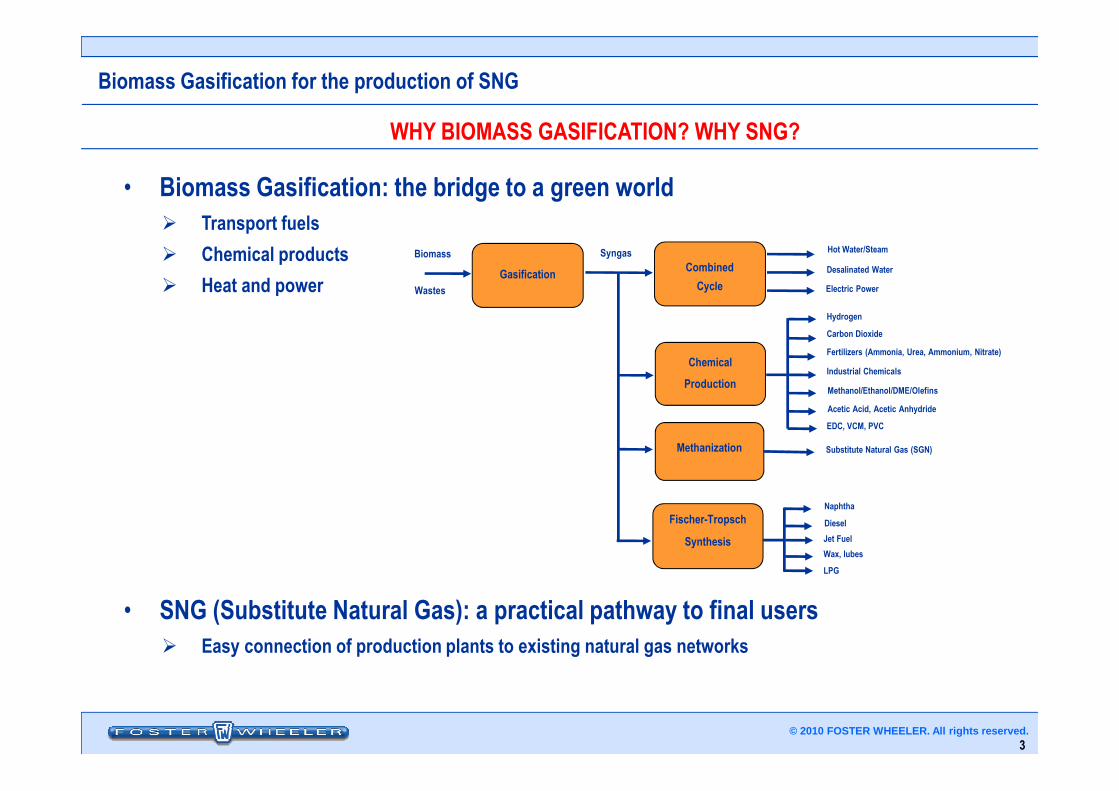
WHY BIOMASS GASIFICATION? WHY SNG?
• Biomass Gasification: the bridge to a green world� Transport fuels
� Chemical products
� Heat and powerCombined
Cycle
Chemical
Production
Hot Water/Steam
Desalinated Water
Electric Power
Hydrogen
Industrial Chemicals
Methanol/Ethanol/DME/Olefins
Fertilizers (Ammonia, Urea, Ammonium, Nitrate)
Carbon Dioxide
SyngasBiomass
Wastes
Gasification
3© 2010 FOSTER WHEELER. All rights reserved.
• SNG (Substitute Natural Gas): a practical pathway to final users� Easy connection of production plants to existing natural gas networks
Methanization
Fischer-Tropsch
Synthesis
Substitute Natural Gas (SGN)
Naphtha
Diesel
Jet Fuel
LPG
Wax, lubes
Acetic Acid, Acetic Anhydride
EDC, VCM, PVC
Biomass Gasification for the production of SNG
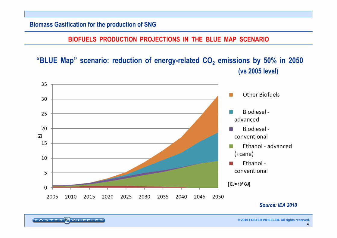
BIOFUELS PRODUCTION PROJECTIONS IN THE BLUE MAP SCENARIO
“BLUE Map” scenario: reduction of energy-related CO2 emissions by 50% in 2050(vs 2005 level)
4© 2010 FOSTER WHEELER. All rights reserved.
Source: IEA 2010
[[[[ EJ= 109 GJ]]]]
Biomass Gasification for the production of SNG
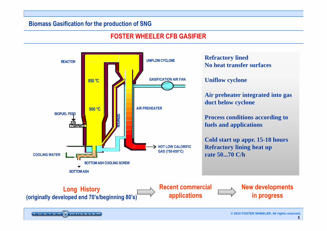
FOSTER WHEELER CFB GASIFIER
Refractory linedNo heat transfer surfaces
Uniflow cyclone
Air preheater integrated into gas duct below cyclone
Process conditions according to
850 °C
900 °C
UNIFLOWCYCLONE
BIOFUEL FEED
REACTOR
AIR PREHEATER
EG
GASIFICATION AIR FAN
5© 2010 FOSTER WHEELER. All rights reserved.
Process conditions according to fuels and applications
Cold start up appr. 15-18 hoursRefractory lining heat uprate 50...70 C/h
BOTTOMASHCOOLINGSCREW
HOT LOW CALORIFICGAS (750-650°C)
BIOFUEL FEED
BOTTOMASH
COOLING WATER
RETU
RNLE
G
Long History(originally developed end 70’s/beginning 80’s)
Recent commercialapplications
New developmentsin progress
Biomass Gasification for the production of SNG
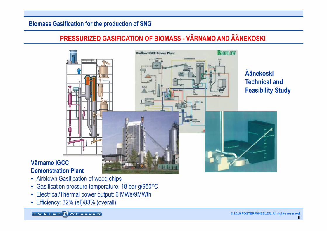
PRESSURIZED GASIFICATION OF BIOMASS - VÄRNAMO AND ÄÄNEKOSKI
ÄänekoskiTechnical and Feasibility Study
6© 2010 FOSTER WHEELER. All rights reserved.
Värnamo IGCC Demonstration Plant• Airblown Gasification of wood chips
• Gasification pressure temperature: 18 bar g/950°C
• Electrical/Thermal power output: 6 MWe/9MWth
• Efficiency: 32% (el)/83% (overall)
Biomass Gasification for the production of SNG
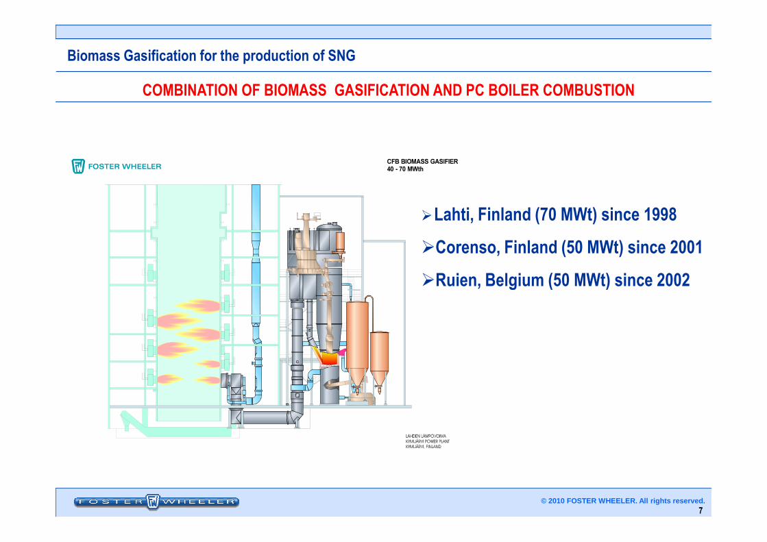
COMBINATION OF BIOMASS GASIFICATION AND PC BOILER COMBUSTION
�Lahti, Finland (70 MWt) since 1998
�Corenso, Finland (50 MWt) since 2001
�Ruien, Belgium (50 MWt) since 2002
7© 2010 FOSTER WHEELER. All rights reserved.
�Ruien, Belgium (50 MWt) since 2002
Biomass Gasification for the production of SNG
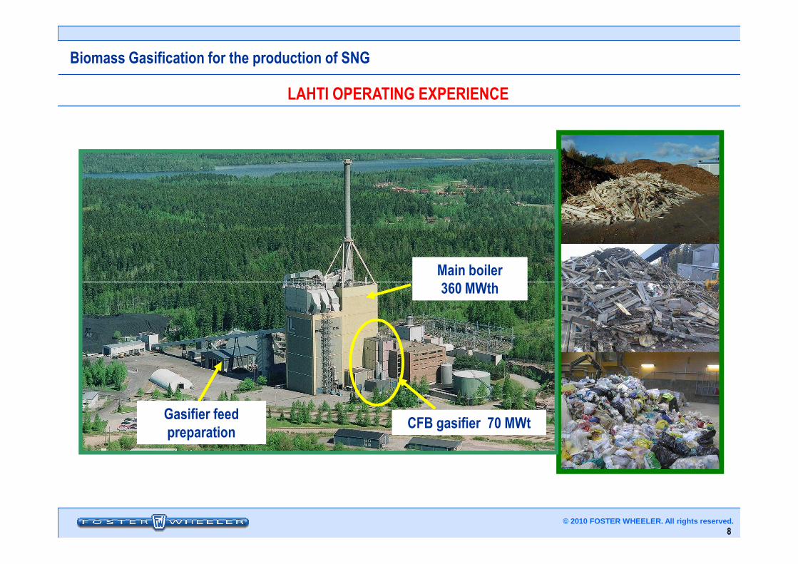
LAHTI OPERATING EXPERIENCE
Main boiler360 MWth
8© 2010 FOSTER WHEELER. All rights reserved.
CFB gasifier 70 MWt
360 MWth
Gasifier feed preparation
Biomass Gasification for the production of SNG
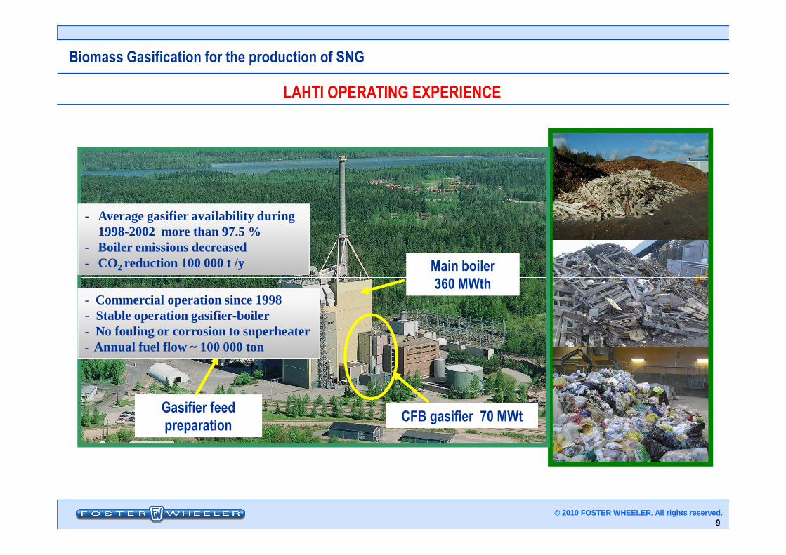
LAHTI OPERATING EXPERIENCE
Main boiler360 MWth
- Average gasifier availability during1998-2002 more than 97.5 %
- Boiler emissions decreased - CO2 reduction 100 000 t /y
9© 2010 FOSTER WHEELER. All rights reserved.
CFB gasifier 70 MWt
360 MWth
Gasifier feed preparation
- Commercial operation since 1998- Stable operation gasifier-boiler- No fouling or corrosion to superheater- Annual fuel flow ~ 100 000 ton
Biomass Gasification for the production of SNG
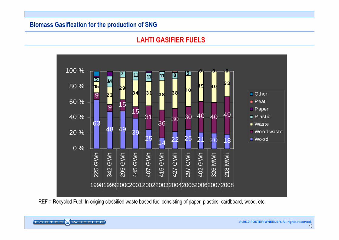
LAHTI GASIFIER FUELS
63
9
9 1515
3136
30 30 40 40 49
15
2329
34 31 38 38 4039 40
335 14
7 11 11 11 8 5 0 0 0
40 %
60 %
80 %
100 %
Other
Peat
Paper
Plastic
10© 2010 FOSTER WHEELER. All rights reserved.
REF = Recycled Fuel; In-origing classified waste based fuel consisting of paper, plastics, cardboard, wood, etc.
6348 49 39
2514 22 25 21 20 18
3136
30 30 40
0 %
20 %
40 %
225
GW
h
342
GW
h
295
GW
h
445
GW
h
407
GW
h
415
GW
h
427
GW
h
297
GW
h
402
GW
h
326
MW
h
218
MW
h
19981999200020012002200320042005200620072008
Waste
Wood waste
Wood
Biomass Gasification for the production of SNG
COMBINATION OF BIOMASS GASIFICATION AND PC BOILER COMBUSTION
• Lower environmental emissions
• Better fuel flexibility
• Possibility to use local fuel (biomass, REF, plastics, etc.) resources in high efficiency steam cycle (say 120 bar, 540°C vs 40 barg, 400°C)
• Low investment and operation costs
11© 2010 FOSTER WHEELER. All rights reserved.
• Low investment and operation costs
• Utilization of existing power plant capacity
• Only small modifications to the main boiler
• High plant availability: gasification unavailability does not cause a power output reduction.
Biomass Gasification for the production of SNG
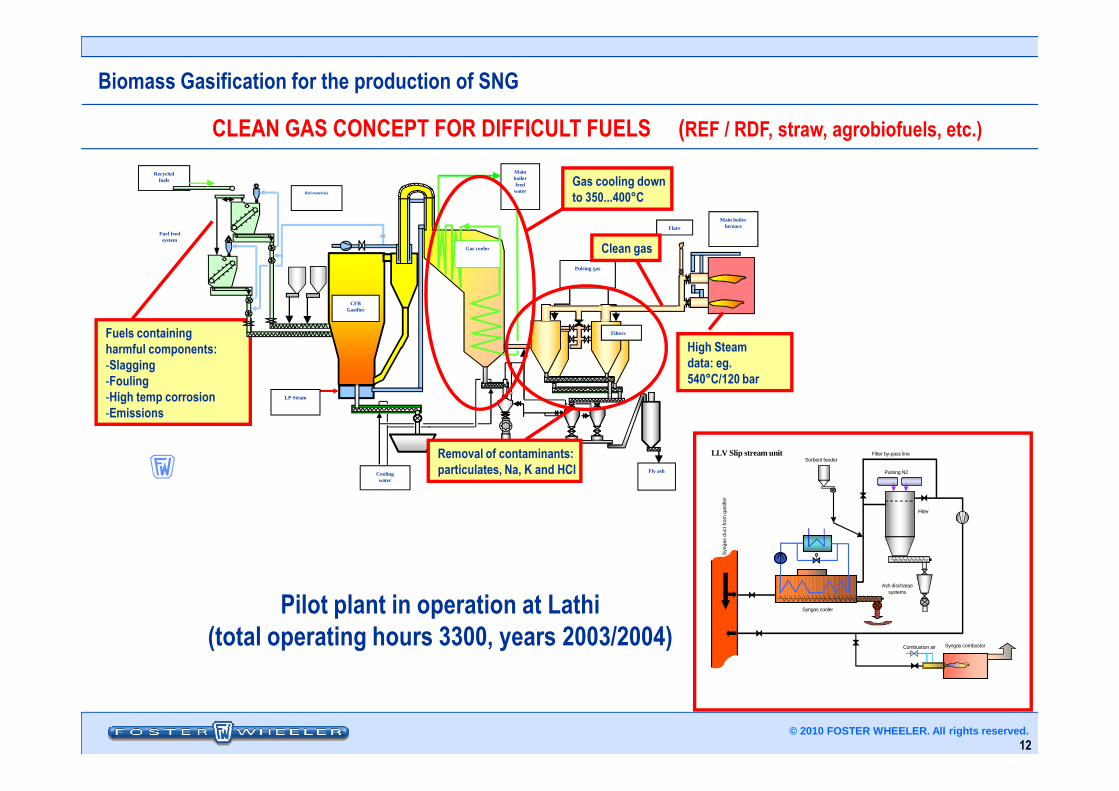
CLEAN GAS CONCEPT FOR DIFFICULT FUELS (REF / RDF, straw, agrobiofuels, etc.)
Fuels containing harmful components:-Slagging-Fouling-High temp corrosion
Main boiler feed
water
Main boiler furnace
Recycled fuels
CFB Gasifier
Pulsing gas
Flare
LP Steam
Filters
Bed materials
Gas cooler
Fuel feed system
Clean gas
Gas cooling downto 350...400°C
High Steamdata: eg.540°C/120 bar
12© 2010 FOSTER WHEELER. All rights reserved.
-High temp corrosion-Emissions
Cooling water
LP Steam
Fly ash
Removal of contaminants:particulates, Na, K and HCl
Pilot plant in operation at Lathi (total operating hours 3300, years 2003/2004)
Pulsing N2
Sorbent feeder
Syn
gas
duct
from
gas
ifier
Syngas cooler
Filter
Syngas combustor
LLV Slip stream unit
Combustion air
Ash discharge systems
Filter by-pass line
Biomass Gasification for the production of SNG
FUTURE APPLICATIONS: ULTRA CLEAN GAS DEVELOPMENT FINNISH APPROACH
PHASE 1 - UCG Development Program / 2004 – 2006• Targeted to optimize the gasification process and gas conditioning&cleaning process to
meet the requirements for the Fischer-Tropsch fuels, SNG and other synthesis gasutilization technologies
• Led by VTT; other partners FWE Oy, Neste Oil, Vapo, Andritz, Technical University ofHelsinki, StoraEnso, UPM, M-Real, Metsä-Botnia, PVO
• Testing performed by VTT with various test facilities (pressurized and atmospheric)
PHASE 2 - Long term industrial demonstrations
13© 2010 FOSTER WHEELER. All rights reserved.
PHASE 2 - Long term industrial demonstrations
• NSE-FWEOy testing going on in Varkaus, Finland (2009-2011) with VTT as the main R&Dpartner
ULTRA CLEAN GAS CONCEPT
• Optimised pressurised oxygen-steam fluidised-bed gasification process (FW scope)• Wide range of feedstocks: woody biomass, agrobiomass, peat, waste derived fuels• Optimised gas reforming, dirty shift and ultra cleanup• Liquid biofuel production integrated to pulp and paper industries
Biomass Gasification for the production of SNG
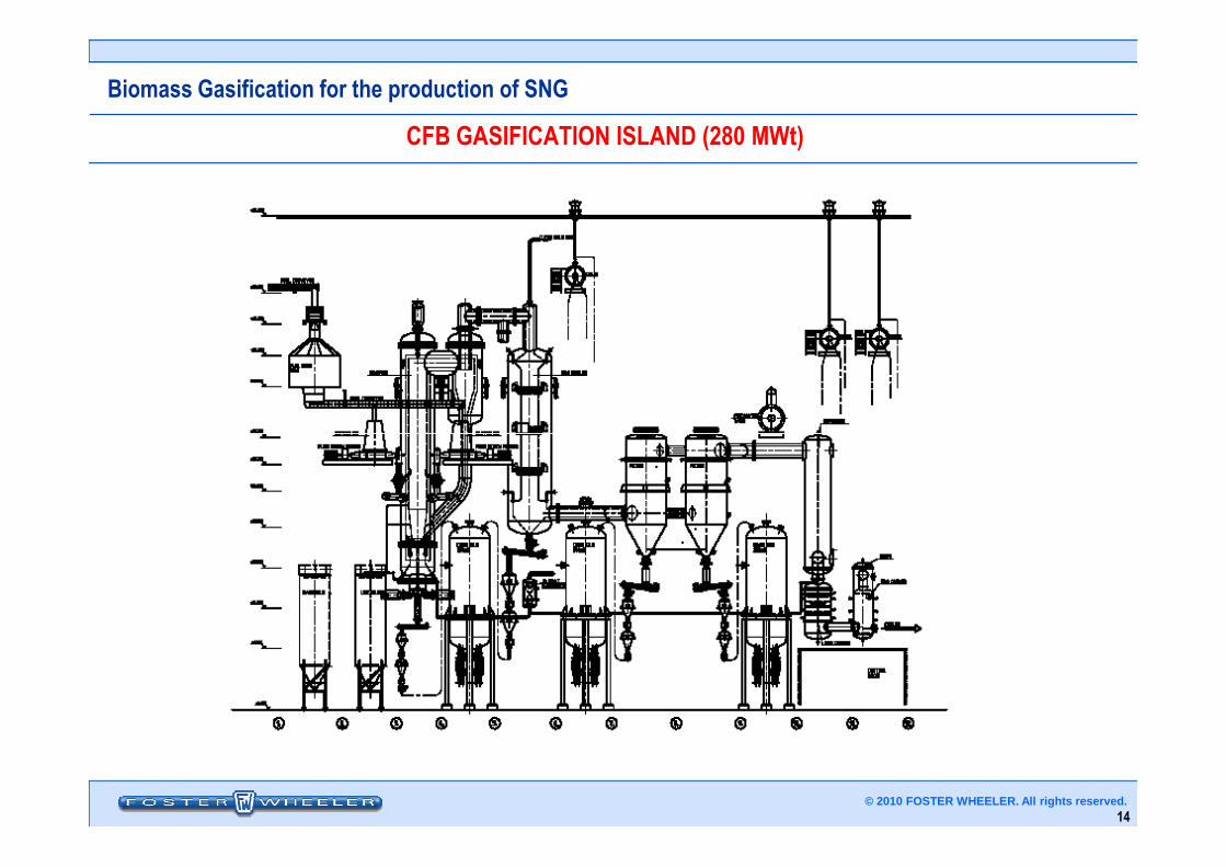
CFB GASIFICATION ISLAND (280 MWt)
14© 2010 FOSTER WHEELER. All rights reserved.
Biomass Gasification for the production of SNG
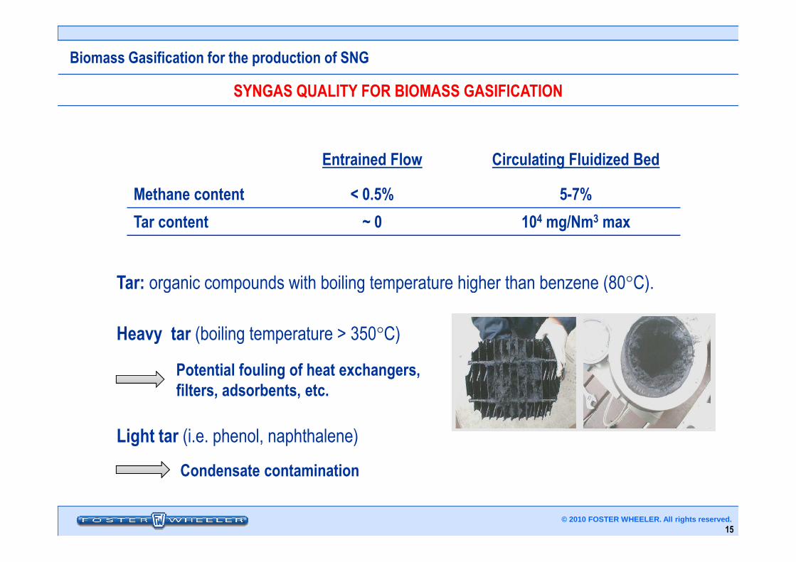
SYNGAS QUALITY FOR BIOMASS GASIFICATION
Tar: organic compounds with boiling temperature higher than benzene (80°C).
Entrained Flow Circulating Fluidized Bed
Methane content < 0.5% 5-7%
Tar content ~ 0 104 mg/Nm3 max
15© 2010 FOSTER WHEELER. All rights reserved.
Tar: organic compounds with boiling temperature higher than benzene (80°C).
Heavy tar (boiling temperature > 350°C)
Light tar (i.e. phenol, naphthalene)
Condensate contamination
Potential fouling of heat exchangers, filters, adsorbents, etc.
Biomass Gasification for the production of SNG
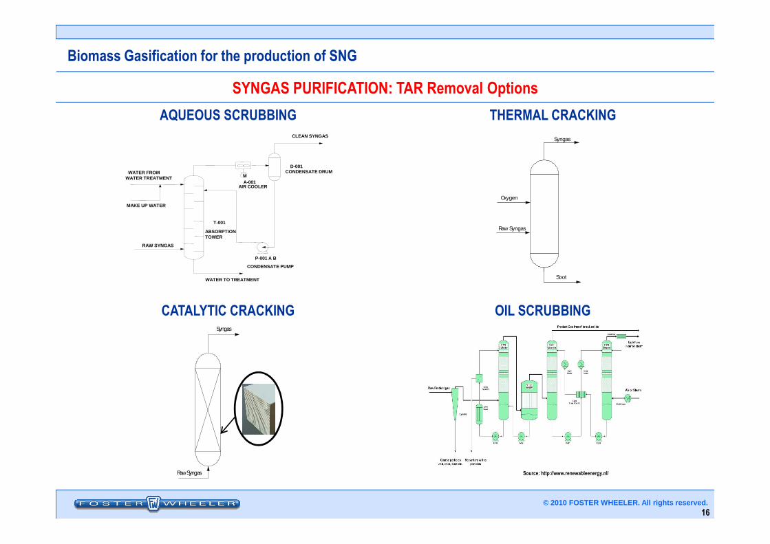
M
P-001 A B
T-001
ABSORPTION TOWER
CONDENSATE PUMP
A-001AIR COOLER
D-001CONDENSATE DRUM
RAW SYNGAS
WATER FROMWATER TREATMENT
CLEAN SYNGAS
MAKE UP WATER
SYNGAS PURIFICATION: TAR Removal Options
Raw Syngas
Syngas
Oxygen
THERMAL CRACKINGAQUEOUS SCRUBBING
16© 2010 FOSTER WHEELER. All rights reserved.
WATER TO TREATMENT
Raw Syngas
Syngas
Soot
Source: http://www.renewableenergy.nl/
CATALYTIC CRACKING OIL SCRUBBING
Biomass Gasification for the production of SNG
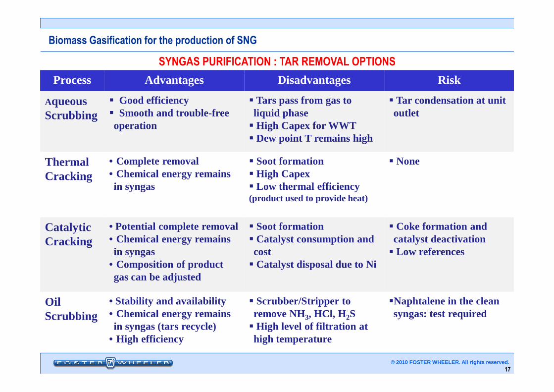
Process Advantages Disadvantages Risk
Aqueous Scrubbing
� Good efficiency� Smooth and trouble-free operation
� Tars pass from gas to liquid phase� High Capex for WWT� Dew point T remains high
� Tar condensation at unit outlet
Thermal Cracking
• Complete removal• Chemical energy remains in syngas
� Soot formation� High Capex� Low thermal efficiency (product used to provide heat)
� None
SYNGAS PURIFICATION : TAR REMOVAL OPTIONS
17© 2010 FOSTER WHEELER. All rights reserved.
(product used to provide heat)
Catalytic Cracking
• Potential complete removal• Chemical energy remains in syngas
• Composition of product gas can be adjusted
� Soot formation� Catalyst consumption and cost� Catalyst disposal due to Ni
� Coke formation andcatalyst deactivation� Low references
Oil Scrubbing
• Stability and availability• Chemical energy remains in syngas (tars recycle)
• High efficiency
� Scrubber/Stripper to remove NH3, HCl, H2S� High level of filtration at high temperature
�Naphtalene in the clean syngas: test required
Biomass Gasification for the production of SNG
Shift and Acid Gas Removal
Syngas composition adjusted by partial shift to facilitate methanation
Physical washing to remove sulphur, followed by adsorption and guard reactorMethanation catalysts require a very low (a few ppb) sulphur content
Benzene/Toluene less than 5 ppm
SYNGAS PURIFICATION AND METHANATION
18© 2010 FOSTER WHEELER. All rights reserved.
Benzene/Toluene less than 5 ppm
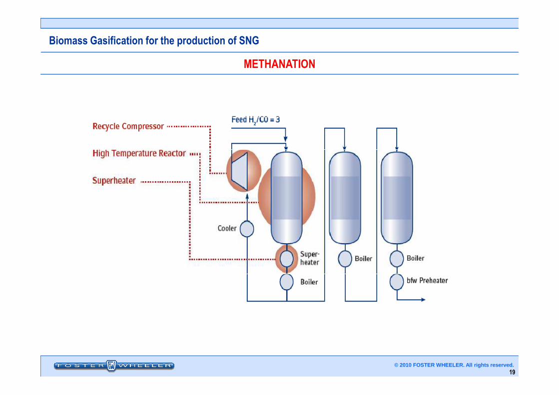
Methanation
CO + 3H2 ⇒⇒⇒⇒ CH4 + H2O
Highly exothermic reaction : 3 to 4 fixed bed catalytic/adiabatic intercooled reactors
Biomass Gasification for the production of SNG
METHANATION
19© 2010 FOSTER WHEELER. All rights reserved.
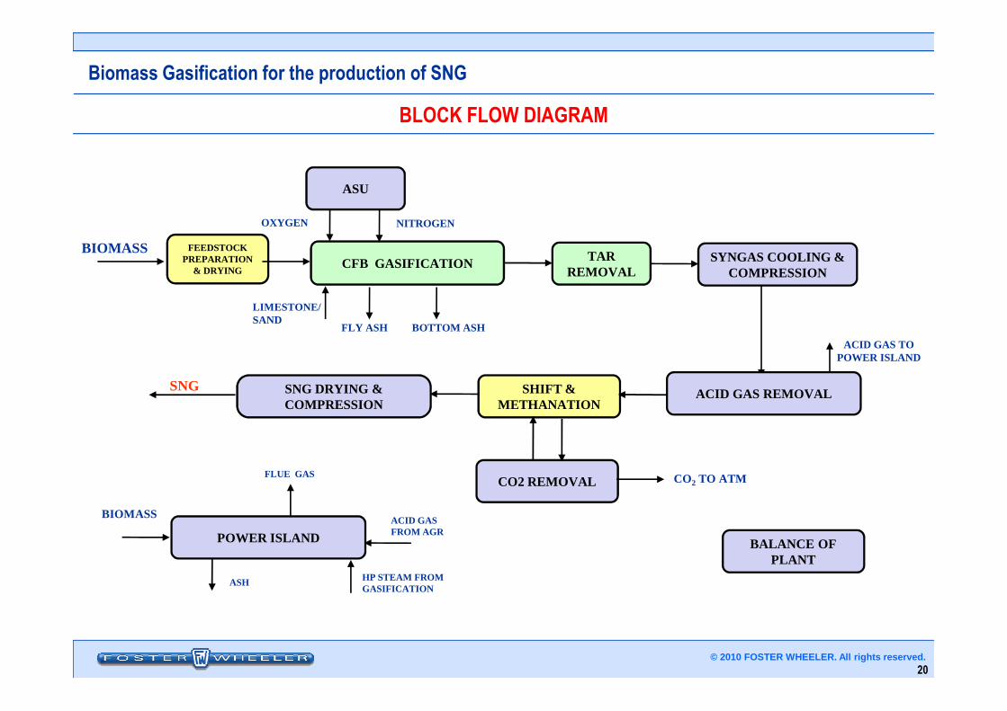
Biomass Gasification for the production of SNG
BLOCK FLOW DIAGRAM
ASU
OXYGEN NITROGEN
FEEDSTOCK PREPARATION
& DRYING
BIOMASSCFB GASIFICATION TAR
REMOVALSYNGAS COOLING &
COMPRESSION
LIMESTONE/SAND
FLY ASH BOTTOM ASH
ACID GAS TO POWER ISLAND
20© 2010 FOSTER WHEELER. All rights reserved.
SNG SNG DRYING & COMPRESSION
SHIFT & METHANATION
POWER ISLAND
CO2 REMOVAL CO2 TO ATM
BALANCE OF PLANT
POWER ISLAND
BIOMASS
ASH HP STEAM FROM GASIFICATION
FLUE GAS
ACID GAS FROM AGR
ACID GAS REMOVAL
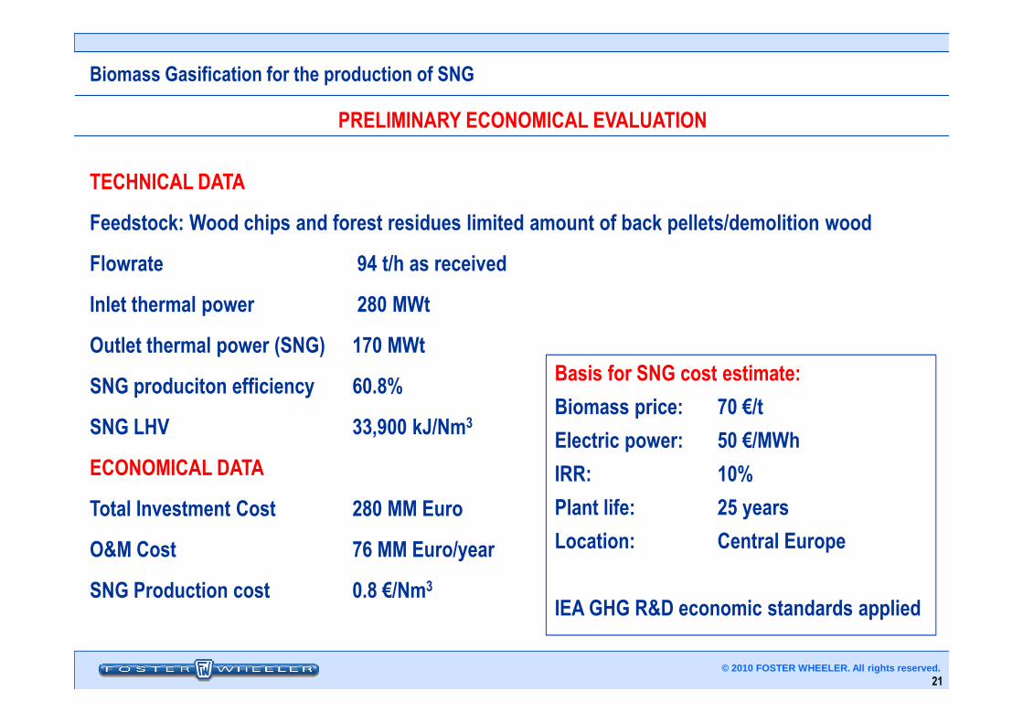
Biomass Gasification for the production of SNG
PRELIMINARY ECONOMICAL EVALUATION
TECHNICAL DATA
Feedstock: Wood chips and forest residues limited amount of back pellets/demolition wood
Flowrate 94 t/h as received
Inlet thermal power 280 MWt
Outlet thermal power (SNG) 170 MWtBasis for SNG cost estimate:
21© 2010 FOSTER WHEELER. All rights reserved.
SNG produciton efficiency 60.8%
SNG LHV 33,900 kJ/Nm3
ECONOMICAL DATA
Total Investment Cost 280 MM Euro
O&M Cost 76 MM Euro/year
SNG Production cost 0.8 €/Nm3
Basis for SNG cost estimate:
Biomass price: 70 €/t
Electric power: 50 €/MWh
IRR: 10%
Plant life: 25 years
Location: Central Europe
IEA GHG R&D economic standards applied
Biomass Gasification for the production of SNG
• The economical evaluation shows that investment fundings, tariff incentivesand/or Carbon taxation are required to make such projects economically viable
• CFB biomass gasification in association with syngas purification and SNGproduction is a promising technology, expected to demonstrate high thermalefficiency, good CAPEX and OPEX in comparison with competing technologies
CONCLUSIONS
22© 2010 FOSTER WHEELER. All rights reserved.
• Some applied technologies need to reach a complete technical maturity:numerous R&D&D activities, also supported by National and European funds, arein progress
• Foster Wheeler is strongly committed to develop and demonstrate both the CFBbiomass gasification and the SNG technology
• Foster Wheeler has developed a SNG production technology together with SüdChemie (a major catalyst supplier).
THANK YOUTHANK YOU
www.fwc.comwww.fosterwheeler.it
Gasification Technology Conference, November 2010 – Washington (USA) © 2010 FOSTER WHEELER. All rights reserved.