Embed Size (px)
Citation preview

Biomass Boiler System Sizing Tool User Manual Version 6.8 3 July 2013
Biomass Heat Accelerator
Biomass Boiler System Sizing Tool
User Manual
Version 6.8 3 July 2013

Biomass Boiler System Sizing Tool User Manual Version 6.8 3 July 2013
Disclaimer The following terms and conditions apply to the Carbon Trust Biomass Decision Support Tool, and are in addition to those generally applicable to the Carbon Trust website. However, in the event of any inconsistency between the provisions of the terms and conditions of the website and those of this tool, the terms and conditions pertaining to this tool shall take precedence.
• This design tool for biomass heating systems has been developed by the Carbon Trust in collaboration with The University of Strathclyde and the Campbell Palmer Partnership Limited, using funding from the Carbon Trust, as a decision support-tool for those investigating and/or specifying biomass heating systems.
• Users of this tool should refer to the detailed guidance within this Manual before use.
• The tool is intended primarily for customers of the Carbon Trust, typically UK businesses and public sector organisations.
• Permission is granted for informational, non-profitable and personal use (including in the course of business) and provided that you do not remove, adapt, alter or obscure any of the information, content or notices (such as copyright and other proprietary notices) contained in the tool. You may not (without the prior written permission of the Carbon Trust or in accordance with the Copyright, Designs and Patents Act 1988) copy, reproduce, republish, store in any medium (including in any other website), make available, whether free of charge or at cost, to the public, or otherwise use the tool (including, but not limited to, "caching" any part of it) for access by third parties or "mirroring" any part of it in any way except for informational, non-profitable and personal use (including in the course of business). Any other use of the tool requires the prior written permission of the Carbon Trust;
• The tool is maintained by The University of Strathclyde; whilst steps have been taken by the University of Strathclyde to ensure that the input data behind it, the algorithms which operate within it and its overall functionality are accurate and reliable, this cannot be guaranteed. The Carbon Trust, its agents, contractors, and sub-contractors, and the University of Strathclyde, its agents, contractors and sub-contractors give no warranty (either express or implied) and make no representation as to its accuracy and accept no liability in any way whatsoever for any omissions or errors contained within it nor for any losses incurred (either direct or indirect) as a result of its use. Any person or organisation using this tool should satisfy themselves as to the validity of any outputs derived from it.

Biomass Boiler System Sizing Tool User Manual Version 6.8 3 July 2013
Contents
Introduction ...................................................................................... 1
Key Features ...................................................................................... 2
Prior Knowledge .................................................................................. 2
1 Using the Tool ................................................................................. 4
1.1 Getting Started ........................................................................... 5
1.1.1 Opening the Tool & Enabling the Macros ................................................... 5
1.1.2 Structure of the Tool .......................................................................... 5
1.1.3 User Inputs on the Main Interface Page ..................................................... 7
1.1.4 Navigating the Tool ............................................................................ 7
1.1.5 Saving the Results .............................................................................. 7
1.2 Demand Module .......................................................................... 8
1.2.1 Specifying a Building ........................................................................... 8
1.2.2 Selecting Options for Non-domestic buildings ........................................... 10 1.2.2.1 Detailed Building Simulation Program, or Heat Meter Measurements. ................... 11 1.2.2.2 Monthly Fuel Bill .................................................................................. 13 1.2.2.3 Embedded Heat Demand Calculator ........................................................... 16 1.2.2.4 Review Results in the Demand Input Sheet ................................................... 21
1.2.3 Selecting Options for a Swimming Pool ................................................... 22
1.2.4 Selecting Options for a Glass House ....................................................... 25
1.2.5 Selecting Options for a Housing Estate .................................................... 28
1.2.6 Reviewing and Editing Building Specifications ........................................... 30
1.3 Financial Inputs ......................................................................... 32
1.4 Biomass Fuel Type ..................................................................... 33
1.4.1 Fuel Data Input - Woodchip ................................................................. 34
1.4.2 Fuel Data Input – Wood Pellets ............................................................. 35
1.5 Biomass Boiler Sizing .................................................................. 36
1.5.1 Inputs .......................................................................................... 37
1.5.2 Warning Messages: ........................................................................... 39
1.5.3 Biomass Boiler System Sizing Results Part I, and Thermal Storage Vessel ........... 42 1.5.3.1 Sizing with a minimum buffer vessel .......................................................... 42 1.5.3.2 Sizing using a thermal store .................................................................... 44 1.5.3.3 Reducing the size of the thermal store ....................................................... 46
1.6 Capital Costs Specification ........................................................... 48
1.7 Biomass Storage ........................................................................ 49
1.8 Biomass Boiler System Sizing Results Part II ....................................... 50
1.9 Financial Analysis and Reporting Module ........................................... 52
2 Underlying Algorithms, Assumptions and Formulae ................................. 54
2.1 Project Location User Input on Main Interface Page .............................. 55
2.2 Demand Module ........................................................................ 55

Biomass Boiler System Sizing Tool User Manual Version 6.8 3 July 2013
2.2.1 Overview ...................................................................................... 55
2.2.2 Heat demand calculations for non-domestic buildings ................................. 56
2.2.2.1 Nomenclature ..................................................................................... 56 2.2.2.2 Scaling Procedure ................................................................................ 57 2.2.2.3 Heat demand from building simulation program, or heat meter measurement data ... 58 2.2.2.4 Heat demand from monthly fuel bill .......................................................... 59 2.2.2.5 Embedded heat demand calculator – non-domestic buildings ............................. 60 2.2.2.6 Ground temperature beneath building ........................................................ 61
2.2.3 Embedded heat demand calculator for glasshouses ..................................... 61
2.2.4 Embedded heat demand calculator for swimming pools ............................... 61
2.2.5 Embedded heat demand calculator for housing estates ................................ 63
2.3 Biomass Fuel & Storage Modules ..................................................... 65
2.3.1 Woodchip Fuels ............................................................................... 65 2.3.1.1 Calorific Value .................................................................................... 65 2.3.1.2 Bulk Density ....................................................................................... 65
2.3.2 Wood Pellet Fuels ............................................................................ 65
2.3.3 Biomass Storage .............................................................................. 65
2.4 Biomass Boiler Module ................................................................. 66
2.4.1 Boiler Sizing Module ......................................................................... 66 2.4.1.1 Buffer Vessels and Thermal Stores ............................................................. 66 2.4.1.2 Minimum Buffer Vessel Sizes and Turndown Ratios for Automatic boilers ............... 67 2.4.1.3 Turndown Ratios for Manual Ignition Boilers ................................................. 68 2.4.1.4 Fuel Consumption of Manual Boilers in Slumber (Kindling) Mode .......................... 68 2.4.1.5 CO2 Emission Factors and Calorific Values of Fuels ......................................... 69 2.4.1.6 Pound Sterling/Euro Exchange Rate ........................................................... 69
2.4.2 Calculation of the Percentage of Heat Energy from Biomass .......................... 69 2.4.2.1 Calculation of the Percentage of Heat Energy from Biomass for the Minimum Buffer Vessel Size and Auxiliary Boiler Sizing .................................................................... 70 2.4.2.2 Calculation of the Percentage of Heat Energy from Biomass for the Optimum Combination of Biomass Boiler and Thermal Store, and Auxiliary Boiler Sizing ..................... 70
2.4.3 Biomass Boiler Results for Different Options ............................................. 71 2.4.3.1 Creation of Sizing Graph ........................................................................ 71 2.4.3.2 Creation of Annual Load Duration Curve ...................................................... 71
2.5 Financial Analysis & Reporting ....................................................... 71
2.5.1 Financial Analysis ............................................................................ 71
2.5.1.1 Pound Sterling/Euro Exchange Rate ........................................................... 71 2.5.1.2 Biomass Boiler System Cost Formula .......................................................... 72 2.5.1.3 Heat loss calculation, and plant room space requirement. ................................ 73 2.5.1.4 Calculation of Fossil Fuel Boiler Costs ......................................................... 74 2.5.1.5 Calculation of Electrical Consumption of Boiler Ancillary Equipment .................... 75
2.5.2 The Report .................................................................................... 76
2.6 Glossary .................................................................................. 76
Appendix 1 - Guidance on Flue Sizing....................................................... 77

Biomass Boiler System Sizing Tool User Manual Version 6.8 3 July 2013
List of Tables Table 1: Building characteristics for inbuilt profile generation. ............................................... 10 Table 2 Boiler Selection Warning Messages ....................................................................... 40 Table 3 Factors for simplified outside temperature profile .................................................... 61 Table 4 Minimum and maximum temperatures for outside temperature bins ............................... 62 Table 5 Heat recovery efficiencies ................................................................................. 63 Table 6 Floor areas of house types ................................................................................. 63 Table 7 Ventilation rates of house types .......................................................................... 63 Table 8 U-values of house constructions, W/m2K ................................................................ 63 Table 9 Equations for Buffer Vessel Sizing, and Turndown Ratios for Automatic Ignition Boilers ......... 67 Table 10 Turndown Ratios for Manual Ignition Boilers ........................................................... 68 Table 11 Typical Slumber Mode Fuel Consumption ............................................................... 68 Table 12: Calorific values and CO2 emissions of fuels. .......................................................... 69 Table 13: Biomass boiler system cost breakdown. ............................................................... 73 Table 14: Auxiliary and back up boiler cost calculation. ........................................................ 74 Table 15 Electrical Consumption of Boiler System Components................................................ 75
List of Figures Figure 1 Financial Analysis and Report ............................................................................. 53 Figure 2: Typical ESP-r generated profile ......................................................................... 57 Figure 3 Calculation of demand from building simulation program, or heat meter data. .................. 58 Figure 4: Calculation of demand from fuel bill data. ............................................................ 59 Figure 5: Calculation of demand using embedded method. .................................................... 60 Figure 6: Biomass boiler and buffer vessel piping schematic. .................................................. 66 Figure 7: Biomass boiler and thermal store piping schematic. ................................................. 66 Figure 8: Typical design day head demand profile, and boiler size. .......................................... 69 Figure 9: Sizing of thermal store and auxiliary boiler. .......................................................... 70 Figure 10: Capital cost ranges for a biomass boiler system. .................................................... 72

Biomass Boiler System Sizing Tool User Manual 1 Version 6.8 3 July 2013
Introduction
The biomass boiler system sizing tool has been designed for both building services design engineers and biomass system installers. The purpose of this manual is to provide both types of users with sufficient information to enable them to use the tool. However, a minimum level of prior knowledge on both building heat load calculations and biomass systems is required in order to understand how to use the tool, and the prior knowledge required is detailed in the next section. Before reading this manual the user should review the definitions given in the glossary at the end of the manual.
The rationale for development of this tool was to provide users who possess limited information about a potential biomass heating project with the means to make an initial feasibility assessment. The tool will provide the user with some quantitative guidance relating to their project, making reasonable assumptions about those aspects that may not yet be subject to detailed design consideration. A more detailed feasibility study should be undertaken by qualified professionals before completing a final system specification, and certainly before making financial commitments. This tool is intended to provide such professionals with a starting point for the key issues to be considered, relating to relative boiler size, thermal store capacity, and auxiliary boiler requirements.
This tool was designed for the pre-feasibility assessment of biomass boiler systems rated between 50kW and 3MW. This was for a number of reasons:
• The Tool is not intended for use in domestic applications;
• The cost calculation formula embedded within the tool is based on an analysis of boilers within this size range; and
• Most public sector and commercial applications are within this size range.
Should the tool be used to assist with the evaluation of biomass systems outside this size range it may not produce sufficiently accurate results.
The tool is a Microsoft Excel workbook, and will run in Excel 2007 or later. The workbook contains macros which will need to be enabled before it can be used. How to do this is described in the section Getting Started – Opening the Tool & Enabling the Macros.
There are hundreds of manufacturers of biomass boiler systems in Europe with differences, small and large, in boiler products reflecting differences in both proprietary design and in design and operating philosophy. Similarly, there are many variations in hydraulic configurations and control systems among manufacturers, and between products from the same manufacturer. In developing the Biomass Boiler System Sizing Tool it has been necessary to make assumptions about system design and operation because both of these are implicit in the calculations carried out by the Tool. It was decided to focus on two different operating strategies against which the sizing of a biomass boiler, associated buffer vessel and/or thermal storage, and auxiliary boiler could be undertaken.
Both the Minimum Buffer Vessel strategy and the Optimum Biomass Boiler/Thermal Store strategy are associated with implicit hydraulic configurations and control strategies which are described in Part 2 of this Manual. The user should take care to ensure that the results produced by the Tool are appropriate to any manufacturer’s system they may be considering, and if not they should adjust the recommended sizings produced by the Tool accordingly.
Users should also interpret the outputs from this tool with a degree of pragmatism. The calculated size of thermal store can be very large, and consideration should be given to the space and loading issues of incorporating such storage vessels on site. The tool includes a variation of the Optimum Biomass Boiler/Thermal Store strategy that allows an upper limit to be placed on the size of the thermal store, in case space and loading capacity are limited.

Biomass Boiler System Sizing Tool User Manual 2 Version 6.8 3 July 2013
Key Features • The tool calculates the heat demand and fuel consumption of a biomass heating system, and
compares it with a reference (existing) fossil fuel fired or electric heating system.
• A wide range of biomass boiler types can be specified, and the tool will guide the user on suitable combinations, including the system’s match for efficient summer load operation.
• The tool includes a capital cost estimator, for the main system components. The user can use their own values if preferred.
• A financial analysis of the project is carried out, including the effect of the Renewable Heat Incentive, and results presented in tabular and summary report formats.
• Heat demand is calculated using one of several methods; data can be input from a detailed building simulation program, from heat meter measurement data, or from fuel bills. Alternatively, the tool can calculate demands based on details of the building.
• The heat demands of housing estates and non-domestic buildings can be calculated, as well as those of swimming pools and glasshouses.
• If a district heat network exists, or is being installed, the distribution losses are accounted for.
• Detailed fuel properties can be specified for wood chip or wood pellet fuels
• The user may specify a system with a buffer vessel (for system overheat protection) or a thermal storage vessel (to reduce boiler size and improve system efficiency across all load conditions). The tool accounts for plant room space cost, and heat losses associated with a thermal storage vessel.
• An auxiliary boiler may be specified to cope with peak loads, or for backup.
• A graphical display assists the user in choosing an optimum combination of biomass boiler and thermal store to meet their requirements, and different options can be easily compared.
• The required size of biomass fuel store can be determined, with several typical types being available for selection.
Prior Knowledge The user requires a certain level of prior knowledge about heat load calculations in buildings, biomass systems, biomass fuels and fossil fuels.
Biomass Boiler Systems
The user is expected to be familiar with the following aspects of biomass boiler systems:
• Types of stokers: underfed auger, overfed auger and hydraulic ram;
• Types of grates: underfed stokers, stoker burners & moving grates;
• Safety devices: rotary valves & flap valves;
• Boiler ceramic linings: the wetter the biomass the greater the quantity and coverage of ceramic lining in a boiler's combustion chamber;
• Fuel extraction/silos: walking floors & rotating scraper extractors, & hopper bottom silos for pellets.

Biomass Boiler System Sizing Tool User Manual 3 Version 6.8 3 July 2013
Building Heat Load Calculations
The user is expected to be familiar with the following aspects of heat load calculations for buildings as assumptions are given in relation to these aspects in the following sections:
• External and internal design temperatures;
• Degree days;
• U-values;
• The concept of lightweight, mediumweight and heavyweight buildings;
• Casual gains: people gains, lighting gains and equipment gains;
• Heat gains from insolation;
• Ventilation requirements for different activities;
• Hot water demands for different building types.
Biomass Fuels
The user requires knowledge of the specifications for both wood chip and wood pellet fuels.
Fossil Fuelled Systems
The user requires an understanding of how the efficiency of fossil fuel boilers has improved over time and the likely efficiency of any existing boiler based on its age, type and condition.

Biomass Boiler System Sizing Tool User Manual 4 Version 6.8 3 July 2013
1 Using the Tool

Biomass Boiler System Sizing Tool User Manual 5 Version 6.8 3 July 2013
1.1 Getting Started
1.1.1 Opening the Tool & Enabling the Macros
When you download the tool, save it in a suitable folder on your PC. It is a Microsoft Excel 2007 workbook with macros (.xlsm). You may change the name of the workbook to suit your project. When saving the tool, save it with file extension {.xlsm}. Due to the complexity of the tool, we are not able to support its use with earlier versions of Excel.
The file size of the un-zipped workbook is less than 10Mb. Although it should open and run on most modern PCs, ensure that you have sufficient free memory (RAM). We recommend at least 1Mb, and more if you have several other applications running simultaneously.
Ensure that the first two digits of the version of the tool you are using correspond to the version number stated on the cover page of this manual. The version number of the tool appears on the main interface sheet when you open the tool.
The Excel workbook contains macros. Macros are code modules that carry out certain functions within the tool and require to be enabled for correct functioning of the tool. For security reasons, Microsoft Excel does not allow such code modules to run automatically. As the user of your PC, you have to determine that the code came from a trusted source. There are several ways of enabling macros, and the method you choose will depend on which Microsoft operating system you have installed on your PC, and your current security settings. The following is general advice, and in case of difficulty you should seek assistance from an IT expert.
When you open the tool, there will either be an Options or an Enable button in your toolbar area to enable macros.
To avoid having to enable macros every time you open the workbook, you can self sign the macros on your PC. Essentially, the process is to create a Digital Certificate on your PC, save this in a trusted certificates folder, then self-sign the macro code in the workbook (Hint: click Developer/Visual Basic/Tools/Digital Signature). Use your Excel Help facility to find out the details of how to do this with your operating system.
You can then change your security level to “disable all macros except digitally signed macros” (or similar depending on your operating system). Use your computer’s Help function to find out how to alter your security setting. Then close and re-open the tool.
It is always possible to set your security to the lowest setting “Enable all Macros”. This is not advisable as you will be vulnerable to attack by malicious codes that might be embedded in macro code modules in other Microsoft Office documents (Word, Powerpoint, etc). Another option may be to save the tool in a “Trusted” folder on your PC. If in doubt seek the advice of an IT expert for further advice that will allow you to run the macros at a higher security setting.
1.1.2 Structure of the Tool
The Biomass Boiler System Sizing Tool comprises a series of linked modules which lead the user through the process of entering building data through to the production of a final report. The main modules are displayed on the Tool’s main interface page, shown below.

Biomass Boiler System Sizing Tool User Manual 6 Version 6.8 3 July 2013
Throughout the tool, enter input data in the white boxes. This may be by selecting a value in a drop down menu, or simply typing a value in the box. In general, every white box should contain a value. A blank box is interpreted as a zero value in Excel, and this may result in some calculations producing an error value, or failure of macros to function correctly. When the tool is first opened many results cells will contain error values; this is normal, as most of the input cells will be empty.

Biomass Boiler System Sizing Tool User Manual 7 Version 6.8 3 July 2013
1.1.3 User Inputs on the Main Interface Page
The first task on opening the tool is to enter your project information.
Project Information: The project information is used as the heading and identifying information for the Report produced at the end of the Tool. The Project Information area can be used to assist the User to identify different Reports produced for the same project. For example the User may wish to run a number of variations by entering different information each time the Tool is run. As a minimum the User must select a “Project Location”. The available locations are Belfast, Birmingham, Cardiff, Edinburgh, Glasgow, London, Manchester and Plymouth. The project location is used in the calculation of heat demand so the location with the closest climate to that of the actual location should be chosen, this not necessarily being the closest geographical location.
1.1.4 Navigating the Tool
Navigation buttons at the bottom of most worksheets of the tool allow the user to navigate forwards (red arrow at bottom right of page) and backwards (red arrow at bottom left of page), according to the sequence shown on the main interface (with a few exceptions). This sequence has been determined to result in a logical order of data entry, but a “Return to Main Interface” button is available top right on most sheets, and from there, any module may be selected. The navigation buttons can be identified by the appearance of a ‘hand’ symbol when the cursor is moved over a navigation button.
1.1.5 Saving the Results
Results can be saved at any time,as an Excel file, with file extension {.xlsm}. It is recommended good practice to do so periodically, using “Save As”, and to update the filename each time the tool is saved, incorporating a date or version number in the filename text. In this way, intermediate calculations are not lost and, if an input error is made, it is easy to go back to a previously saved version.
On occasion, the user will be directed to press a “Save” or “Update” button within the tool. After doing so, wait a few seconds for the command to complete execution.
Typical Worksheet
Back button Forward button
Return to Main Interface

Biomass Boiler System Sizing Tool User Manual 8 Version 6.8 3 July 2013
1.2 Demand Module
1.2.1 Specifying a Building
In order to calculate the capacity of the biomass boiler, auxiliary boiler, and buffer vessel or thermal store, the Tool needs to estimate the hourly profile of heat demand in a day. The tool will also estimate the annual heat demand, including the proportion that is serviced by the biomass boiler.
The Demand Module provides several ways of specifying buildings, for a variety of different building types. When you click on the Demand Module button, you will see a sheet that shows a summary of heat demands for up to 10 different building specifications. When first selecting this sheet, only one building specification input selection box will be visible. For each building specification, the user can select from four different input modes, allowing users to input energy and buildings data. The four input options are:
• Data from a detailed building simulation program
• Heat meter measurement data
• Data from fuel bills
• An embedded demand calculator requiring the input of detailed building data
The first three options allow the user to specify a non-domestic type of building, and assume that the user already has information to hand about the building’s heat demand.
The fourth option, the Embedded Demand Calculator, allows the user to specify:
• A non-domestic building
• A swimming pool
• A glass house
• A housing estate (domestic)
In these cases, it is assumed that the user has no demand data from any other source, and the tool has to estimate this based on user inputs about the building or houses.

Biomass Boiler System Sizing Tool User Manual 9 Version 6.8 3 July 2013
The user should enter the number of building specifications he intends to input to the tool. Use the up arrow to increase the number. You may have to wait a moment for the sheet to update. For example, if the user has two non-domestic buildings, and a swimming pool, then 3 specifications should be requested, using the up arrow. If the user has one non-domestic building, two glasshouses, and a housing estate, then 4 should be selected. Note that a housing estate is counted as one building specification, even though a number of houses of different types may be specified within a housing estate. Note that only one housing estate can be specified. Before entering any of the demand input modules, the user should give each building specification a meaningful name, replacing the default Building 1, Building 2, etc.
It is also possible to select the number of identical buildings of each type. So, for example, if the user has specified a building as a hospital ward block, and the project has three such identical blocks on site, the user can enter 3. The only effect of this selection is to multiply the design day and annual heat demands for one building by the figure entered.
It will often be the case, when a biomass boiler system serves several buildings, and especially a housing estate, that a district heat distribution system will be included as part of the project. The user may specify the continuous distribution network power losses. This will be expressed as a percentage of the peak total demand on the winter design day, for all the buildings specified within the tool.
Building Heat Demand Inputs
No of building specifications
2 Continuous distribution network power losses: 0.0% of peak load = 0.0 kW
Building name Office
Number of buildings of this type
1
Building name Office2
Number of buildings of this type
2
Total heating energy required
Average heat demand at design day: kW
Energy demand at design day: kWh
Annual energy demand: kWh
248
5,950
194,467
Proceed Save Retrieve
Proceed Save Retrieve
Peak load, 486
0.0
100.0
200.0
300.0
400.0
500.0
600.0
0:00 2:00 4:00 6:00 8:00 10:00 12:00 14:00 16:00 18:00 20:00 22:00
Lo
ad
(k
W)
Time (h)
Hourly load profile at design day
Total demand
Peak load
Off ice
Off ice2
Return to Main Interface
Demand Data Source
Detailed Building Simulation Program
Heat meter measurement
Monthly fuel bill
Embedded demand calculator
Demand Data Source
Detailed Building Simulation Program
Heat meter measurement
Monthly fuel bill
Embedded monthly demand calculator
Fuel bill

Biomass Boiler System Sizing Tool User Manual 10 Version 6.8 3 July 2013
1.2.2 Selecting Options for Non-domestic buildings
The demand profile for non-domestic buildings may be user defined, or an inbuilt profile may be selected within the embedded demand calculator. Irrespective of this, in order to estimate the annual heat demand, the tool uses inbuilt profiles and a weather data frequency distribution for the chosen Project Location. The following building characteristics are required (with typical values shown as a guide):
Low/Light/Short Medium/Long High/Heavy/Continuous
Building thermal mass
Little/no exposed thermal mass at internal surfaces
Substantial exposed thermal mass, at internal surfaces, eg floor
Exposed thermal mass on floor and walls, partitions
Area of glazing 15% of wall façade 30% of wall façade 60% of wall façade
Level of insulation U-value around 0.7, single glazed
U-value around 0.35, double glazed (Part L 2002)
U-value around 0.25, low-e double glazed (Part L 2005)
Level of occupancy 8:00 - 18:00hrs
5 days / week.
7:00 – 23:00 hrs
7 days / week.
Continuous
Table 1: Building characteristics for inbuilt profile generation. As described above, any of the input options for a building specification may be selected for a non-domestic building, within the Building Heat Demand Inputs sheet. A detailed description of the input pages for non-domestic buildings follows.

Biomass Boiler System Sizing Tool User Manual 11 Version 6.8 3 July 2013
1.2.2.1 Detailed Building Simulation Program, or Heat Meter Measurements.
If you already have a dynamic model of your building in one of the many building simulation tools, then you can use this to generate some of the input data required by the Sizing Tool. Alternatively you may have the same data from actual heat meter measurements.
From the Building Heat Demand Inputs sheet, select Detailed Building Simulation Program, or Heat meter measurement, and click the Proceed button.
Depending on which option you select, a page similar to that below will appear. The data required are:
Heating design temperature: Enter the external temperature for the day for which the design day load profile was generated / measured.
Building Characteristics: As previously described. Drop down menus allow the values to be selected.
24 hourly values of heat demand (load) for the design day: The data required is the heat demand, or heat delivered to the building load. Obtain this data by running a simulation for the coldest day of the year. You should include all internal heat gains, ventilation losses, and domestic hot water load. In the case of metered data, enter the 24 hourly metered demands that correspond to the coldest day, or a day that represents your design condition.
Total building floor area and occupancy: Enter the values required.
Proceed Save Retrieve
Demand Data Source
Detailed Building Simulation Program
Heat meter measurement
Monthly fuel bill
Embedded demand calculator
Fuel bill
Biomass Boiler System Sizing Tool User Manual 12 Version 6.8 3 July 2013
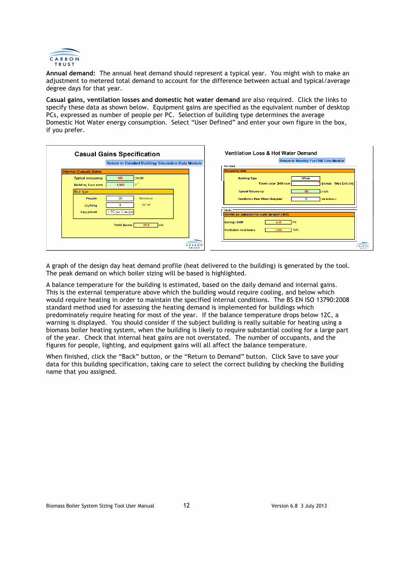
Annual demand: The annual heat demand should represent a typical year. You might wish to make an adjustment to metered total demand to account for the difference between actual and typical/average degree days for that year.
Casual gains, ventilation losses and domestic hot water demand are also required. Click the links to specify these data as shown below. Equipment gains are specified as the equivalent number of desktop PCs, expressed as number of people per PC. Selection of building type determines the average Domestic Hot Water energy consumption. Select “User Defined” and enter your own figure in the box, if you prefer.
A graph of the design day heat demand profile (heat delivered to the building) is generated by the tool. The peak demand on which boiler sizing will be based is highlighted.
A balance temperature for the building is estimated, based on the daily demand and internal gains. This is the external temperature above which the building would require cooling, and below which would require heating in order to maintain the specified internal conditions. The BS EN ISO 13790:2008 standard method used for assessing the heating demand is implemented for buildings which predominately require heating for most of the year. If the balance temperature drops below 12C, a warning is displayed. You should consider if the subject building is really suitable for heating using a biomass boiler heating system, when the building is likely to require substantial cooling for a large part of the year. Check that internal heat gains are not overstated. The number of occupants, and the figures for people, lighting, and equipment gains will all affect the balance temperature.
When finished, click the “Back” button, or the “Return to Demand” button. Click Save to save your data for this building specification, taking care to select the correct building by checking the Building name that you assigned.

Biomass Boiler System Sizing Tool User Manual 13 Version 6.8 3 July 2013
1.2.2.2 Fuel Bill
In this case, the user does not have a daily demand profile, but can estimate the actual building demand based on fuel bill data for the coldest day of the year. From the Building Heat Demand Inputs sheet, select Fuel bill, and click the Proceed button. A sheet similar to that below will appear.
From meter readings or fuel delivery information, estimate the fuel consumption on the coldest day in the year. Readings should be for total fuel consumption, including domestic hot water, but not including electrical loads like lighting, small power, etc. Note that for this option, the primary fuel consumed is specified, unlike all other options where building heat demand (heat delivered to the building) is specified. The data required are:
Calendar year for which data is applicable: Enter the year.
Degree days in the coldest day of the calendar year for which the fuel data is available: Use the www.vesma.com website to find the degree days in your area corresponding to that day of the year entered above. This allows the tool to adjust the coldest day heat demand to a demand for the design day, at the outside temperature that you specify.
Insert total fuel energy consumption for the coldest day: This is the total fuel use for heating for the coldest day and must be entered in kWh.
Annual fuel energy use: This is the total fuel use for heating for the specified calendar year and must be entered in kWh.
Existing boiler efficiency: A realistic figure for the existing boiler’s seasonal efficiency should be chosen. This is required to convert fuel use into heat demand. A good indication can be obtained from CIBSE Guide B, figure 1.4 which shows fossil fuel boiler seasonal efficiency versus average boiler load for different fossil fuel boiler types.
Heating design temperature: Enter the outside temperature for the day for which the design day load profile was generated / measured.
Desired internal temperature: Enter the temperature during the occupied period.
Building Characteristics: As previously described. Drop down menus allow the values to be selected.
Total building floor area and occupancy: Enter the values required.
Casual gains, ventilation losses and domestic hot water demand are also required. Click the links to specify these data. A graph of the design day heat demand profile is output by the tool. The peak demand on which boiler sizing will be based is highlighted.

Biomass Boiler System Sizing Tool User Manual 14 Version 6.8 3 July 2013
1
As with the previous demand input method, a balance temperature for the building is estimated, based on the design day demand and internal gains. If the balance temperature drops below 12C, a warning is displayed. You should consider if the subject building is really suitable for heating using a biomass boiler heating system, when the building is likely to require substantial cooling for a large part of the year. Check that internal heat gains are not overstated. The number of occupants, and the figures for people, lighting, and equipment gains will all affect the balance temperature.

Biomass Boiler System Sizing Tool User Manual 15 Version 6.8 3 July 2013
When finished, click the “Back” button, or the “Return to Demand” button. The Building Heat Demand Inputs sheet will reappear. Click Save to save your data for this building specification, taking care to select the correct building by checking the Building name that you assigned.

Biomass Boiler System Sizing Tool User Manual 16 Version 6.8 3 July 2013
1.2.2.3 Embedded Heat Demand Calculator
If no other heat demand data is available, use the Embedded Calculator which will estimate annual heat demand, and select an inbuilt design day heat demand profile according to the user inputs. The annual heat demand is calculated by multiplying heat demands for a series of temperature bins, calculated using a simple energy balance method similar to the BS EN ISO 13790:2008 standard approach, by the frequency of occurrence of each temperature. This requires some basic building geometric, fabric, solar, occupancy, and casual gain properties to be entered. As with the other heat demand options, the thermal characteristics also require to be entered, in order to select the most appropriate heat demand profile.
Important: The data must describe a building with a heating demand at most times of the year. The BS EN ISO 13790:2008 method will fail (erroneous demand data will result) if a building is described that essentially needs to be cooled. A balance temperature will be calculated (see below) to assist in making this assessment.
From the Building Heat Demand Inputs sheet, select Embedded demand calculator, and click the Proceed button.
A window will open allowing you to select from the different building specifications types available. Select Non-domestic Building, and Click the Continue button.
A new sheet will open, with several input areas which will now be described.
Select Building Type
Click here to continue
Building Type
Non-domestic Building
Swimming Pool
Glass House
Housing Estate

Biomass Boiler System Sizing Tool User Manual 17 Version 6.8 3 July 2013
The data required in the first two boxes are:
Internal temperature: Enter the temperature during the occupied period.
Building thermal mass: As previously described. A drop down menu allows the value to be selected.
Outdoor design temperature: Enter the external temperature for the day to which the design day load profile applies.
Overall Building Dimensions: Insert the total area of first, second and third floors, and floor heights. If there are more than three floors, the third floor area should be specified as the total area of the remaining floors, and the height should be the total height of these floors.
Embedded Heat Demand Calculator
Building name: HQ office
Scotland W
Site location
oC
Overall building dimensions
First floor Volume (m3)
Area (m2) 2,400 3 7,200
Second floor
Area (m2) 2,400 3 7,200
Third and other floors
Area (m2) 2,400 3 7,200
Building floor area 7,200 Total 21,600
Height(m)
Height(m)
Internal temperature (oC) 21.0
Height(m)
Building thermal
mass
LightweightGlasgow
Outdoor design
temperature-3
Building Info

Biomass Boiler System Sizing Tool User Manual 18 Version 6.8 3 July 2013
Fabric Heat Loss:
Areas and U-values of doors, windows, rooflights, walls and roof: Enter values as appropriate, starting with the walls. The wall and window areas specified are the total wall and window areas for all floors on each façade. When you enter the areas of doors and windows, the openings in each wall and the resulting net wall areas are automatically calculated.
Ground Floor and Roof: Enter the U-values of the Ground Floor (between occupied area and ground) and the Roof.
Fabric heat lossGross Area Openings area Net Area (m2) U value Heat losses
m² m² m² W/m2K W/K
Door 1 5 3.00 15
Door 2 5 3.00 15
Window 1 240 3.00 643
Window 2 90 3.00 241
Window 3 240 3.00 643
Window 4 90 3.00 241
Window 5 0
Window 6 0
Rooflights 0
Ground floor 2,400 1.00 2400
0
Wall 1 (contains Window 1 and Door 1) 720 245 475 1.00 475
Wall 2 (contans Window 2 and Door 2) 270 95 175 1.00 175
Wall 3 (contains Window 3) 720 240 480 1.00 480
Wall 4 (contains Window 4) 270 90 180 1.00 180
Wall 5 (contains Window 5) 0 0 0
Wall 6 (contains Window 6) 0 0 0
Roof 2,400 0 2,400 1.00 2400
0
Total area 6780
Fabric heat loss coeff 7,908 W/K

Biomass Boiler System Sizing Tool User Manual 19 Version 6.8 3 July 2013
Average Occupancy: Enter the average occupancy the during occupied period.
Ventilation rate when occupied: Enter the required ventilation rate. Note that in older ‘leaky’ buildings this rate may need to be increased to represent the actual ventilation rate. A too low value may suggest a building that requires cooling in summer to avoid overheating. The tool is not designed to cater for this.
Building type: Used here for the calculation of the DHW load. Select from drop down menu. You may select “User defined”, in which case an additional input box will appear. Enter the DHW consumption in litres / person / day.
As a sanity check, review the reported values of building heat loss coefficient (W/K), average thermal transmittance (W/m2K) and hot water demands, and satisfy yourself that the values are sensible.
Building occupancy Ventilation losses
Average occupancy 500 people Air flow 6.0 m³/s
Ventilation rate when occupied 12 litre/s/person
Building type Offices
Ventilation heat losses coeff 7,236 W/K
extra ventilation heat loss coeff 3618 W/K
Building heat losses Hot water demand (HWD)
Heat loss coefficient 15,144 W/K Average HWD 21 kW
Thermal transmitance 2.1 W/m²K Average energy consumption 14,875 kWh (month)

Biomass Boiler System Sizing Tool User Manual 20 Version 6.8 3 July 2013
Solar gains: On the right hand side of the sheet, input the orientation, shading, total area on façade, inclination from horizontal, type of glazing, and frame type. Use the drop down menus where provided.
Internal (Casual) gains:
Enter the heat gain per person, lighting load in W per m2, and the equipment load, expressed as number of PCs per person.
Building characteristics: Enter the remaining building characteristics using the drop down menus.
Building Balance Temperature
As before, a balance temperature for the building is shown. If the balance temperature drops below 12C, a warning is displayed. You should consider if the subject building is really suitable for heating using a biomass boiler heating system, when the building is likely to require substantial cooling for a large part of the year. Check that you have entered realistic values for insulation of walls and windows, and that internal heat gains are not overstated.
Solar gainsIrradiance data
N >80% 0.3 90 90 Double glazed (air or argon filled) 0.76 PVC-U 0.7
S >80% 0.3 240 90 Double glazed (air or argon filled) 0.76 PVC-U 0.7
E >80% 0.3 90 90 Double glazed (air or argon filled) 0.76 PVC-U 0.7
W >80% 0.3 240 90 Double glazed (air or argon filled) 0.76 PVC-U 0.7
E 80% - 60% 0.54 90 Triple glazed (air or argon filled) 0.68 Wood 0.7
SW 80% - 60% 0.54 90 Double glazed (Low-E, soft coat) 0.63 Wood 0.7
S 80% - 60% 0.54 90 Single glazed 0.85 Metal.thermal break 0.8
SE 80% - 60% 0.54 90 Triple glazed (air or argon filled) 0.68 Wood 0.7
E 80% - 60% 0.54 90 Window with secondare glazing 0.76 Metal 0.8
NE 80% - 60% 0.54 90 Triple glazed (Low-E, hard coat) 0.64 PVC-U 0.7
E 80% - 60% 0.54 90 Triple glazed (High-E, soft coat) 0.57 Wood 0.7
W 80% - 60% 0.54 90 Double glazed (air or argon filled) 0.76 Metal 0.8
Check Areas!
Total solar heat gains: W
Total solar heat gains after utilization factor: W
Internal (Casual) gains (W)
W/person 45,000
W/m2 28,800
25,000
98,800
Total internal gains after utilization factor: kW
Equipment
4
1 PC per 4 people
Gain type Use
People
Lighting
90
1,924
% of façade
permanently
shaded by
obstacles
Inclination
from
horizontal
Type of glazing
Total
glazing area
on façade
(m2)
Total gains
(W)
Orientation Frame type
89
2,131
Glasgow

Biomass Boiler System Sizing Tool User Manual 21 Version 6.8 3 July 2013
Various parameters output by the BS EN ISO 13790:2008 calculation are displayed. The sheet also shows the calculated design day and annual heat demands, and the design day profile, according to the user selections.
When finished, click the “Back” button, or the “Return to Demand” button. The “Select Building Type” window will be displayed. Click the “Back” button again, to return to the Heat Demand Inputs sheet. Click Save to save your data for this building specification, taking care to select the correct building by checking the Building name that you assigned.
1.2.2.4 Review Results in the Demand Input Sheet
The design day heat demand profile for the building that has just been specified will be shown on the graph, along with the profiles for any other building specifications input, and a total profile for all buildings so far specified. The average heat demand on the design day, the total energy demand on the design day, and the annual energy demand are all shown to the right of the graph. These figures include any distribution network losses that have been specified.
Before proceeding to specify another building, it is important to click the Save button for the building just specified. This will save all the input data for that building, for later editing using the Retrieve button.
It is vital that the user Saves a building specification before proceeding to specify another building. Failure to do this may result in the loss of the data, which will then need to be completely re-entered.
In the example below, two buildings have been specified, with one of each type.
Total heating energy required Hourly demand profile
Average heat demand at design day: kW Building thermal mass
Level of insulation
Energy demand at design day: kWh Area of glazing
Level of occupany
Annual energy demand: kWh Heating days a week
Time
Balance temperature:oC 00:00
WARNING: Low Balance Temperature – See Manual for Information 01:00
02:00
03:00
04:00
05:00
06:00
07:00
08:00
09:00
10:00
11:00
12:00
13:00
14:00
15:00
16:00
17:00
18:00
19:00
20:00
21:00
22:00
23:00
454
0
0
0
Medium
0
Load (kW)
0
Long
Medium
Lightweight
402
353
5
321
427
317
371
19
318
335
326
322
418
319
14.3
392
319
387
327
326,200
6,467
339
269
Peak Load, 453.8
0.0
50.0
100.0
150.0
200.0
250.0
300.0
350.0
400.0
450.0
500.0
Lo
ad
(kW
)
Time
Hourly load profile at design day
Off ice
Peak Load

Biomass Boiler System Sizing Tool User Manual 22 Version 6.8 3 July 2013
1.2.3 Selecting Options for a Swimming Pool
From the Building Heat Demand Inputs sheet, select Embedded monthly demand calculator for the next building to be specified, and click the Proceed button.
In the Select Building Type window, select Swimming Pool, and click Continue.
An Embedded Calculator sheet will open for specifying a Swimming Pool. Many of the inputs will be similar to those for a non-domestic building, but a few are unique to the definition of a swimming pool.
Building Heat Demand Inputs
No of building specifications
2 Continuous distribution network power losses: 0.0% of peak load = 0.0 kW
Building name Office
Number of buildings of this type
1
Building name Office2
Number of buildings of this type
2
Total heating energy required
Average heat demand at design day: kW
Energy demand at design day: kWh
Annual energy demand: kWh
248
5,950
194,467
Proceed Save Retrieve
Proceed Save Retrieve
Peak load, 486
0.0
100.0
200.0
300.0
400.0
500.0
600.0
0:00 2:00 4:00 6:00 8:00 10:00 12:00 14:00 16:00 18:00 20:00 22:00
Lo
ad
(k
W)
Time (h)
Hourly load profile at design day
Total demand
Peak load
Off ice
Off ice2
Return to Main Interface
Demand Data Source
Detailed Building Simulation Program
Heat meter measurement
Monthly fuel bill
Embedded demand calculator
Demand Data Source
Detailed Building Simulation Program
Heat meter measurement
Monthly fuel bill
Embedded monthly demand calculator
Proceed Save Retrieve
Demand Data Source
Detailed Building Simulation Program
Heat meter measurement
Monthly fuel bill
Embedded monthly demand calculator
Select Building Type
Click here to continue
Building Type
Non-domestic Building
Swimming Pool
Glass House
Housing Estate
Fuel bill
Fuel bill
Fuel bill

Biomass Boiler System Sizing Tool User Manual 23 Version 6.8 3 July 2013
The data required in the first two boxes are:
Type of Pool: Enter the pool type from the drop down menu. A typical pool water temperature based on this selection is displayed to the right. The Pool hall will operate at a temperature 1K above this. The rate of pool hall ventilation is also based on the selection. The options are:
Type of pool Pool water temp. C Ventilation l/s/m2
Hotel/school 28 10
Private leisure 29 10
Public pool (no water features) 29 10
Leisure pool (few water features) 29 14
Leisure pool (many water features) 29 18
Olympic pool 27 8
The pool hall relative humidity is assumed to be 60% for all pool types.
Is a pool cover used outside operating hours?: This is strongly recommended, to reduce evaporative loss from the pool surface. Select Yes or No from the drop down menu.
Operating hours per day: If the pool is typically used only during the working day, select Short. If the pool is often opened into the evening, then select Long.
Ground insulation: modern pools will be insulated to reduce heat loss from the pool water into the ground. This insulation should extend under the pool surround to the external walls. If the pool is insulated in this way, select Yes, otherwise select No.
Heating days a week: Select 5 or 7 from the drop-down menu.
Outdoor design temperature: Enter the external temperature for the day to which the design day load profile applies.
Pool Length and Width: Insert the length and width of the actual pool. For odd shaped pools, enter values here that equate to the same pool area. If there is more than one pool, enter values that equate to the total area of all pools.
Pool Hall area and height: Enter values for the overall pool hall floor area and average height.

Biomass Boiler System Sizing Tool User Manual 24 Version 6.8 3 July 2013
Fabric heat loss of pool hall: the data to be input is exactly the same as for a non-domestic building (see section 1.2.2.3).
Occupancy: Enter the average number of bathers during the operating hours.
Ventilation rate outside operating hours: Enter “Ventilation off”, or 50% or 100% of the ventilation rate during operating hours.
Type of Heat Recovery System: There are four options:
• No heat recovery. The ventilation air is heated to the pool hall temperature, and 100% extracted to outside, with no heat recovery. This option will result in a very high heat demand.
• Run-around coil: Heat is transferred via a heat exchanger in the extract duct to a water circulation loop, connected to a second heat exchanger in the intake duct. This will recover some of the sensible heat and, during colder weather, some of the latent heat in the exhaust air stream.
• Air to air heat exchanger: This will transfer heat directly from the exhaust air to the intake air, via a heat exchanger, usually of the parallel plate type. This is somewhat more efficient than a run-around coil.
• Heat pump dehumidifier: A heat pump system will transfer a high proportion of the sensible and latent heat from the exhaust air to the intake air, and may also contribute to pool heating. This is by far the most efficient option for a pool hall.
Solar gains: as for fabric losses, the input data is the same as for non-domestic buildings (section 1.2.2.3)
A breakdown of the average heat losses on the design day are shown. Domestic Hot Water demand is based on 2.3 kWh/bather. The user may decide to re-visit some selections based on this feedback.
Occupancy, ventilation and heat recovery
Average number of bathers 20 people
Ventilation rate outside operating hours Ventilation off
Type of Heat Recovery System Heat pump dehumidifier
Heat loss breakdown and DHW
Pool water heat demand (occupied) 35.8 kW
Pool water heat demand (unoccupied) 11.2 kW
Ventilation heat demand (occupied) 23.9 kW
Ventilation heat demand (unoccupied) 8.3 kW
Fabric heat demand 64.4 kW
DHW demand (occupied) 46.0 kW
Total heating energy required Hourly demand profile
Average heat demand at design day: kW Time
0 00:00
Energy demand at design day: kWh 0 01:00
0 02:00
Annual energy demand: kWh 0 03:00
0 04:00
0 05:00
0 06:00
1 07:00
1 08:00
1 09:00
1 10:00
1 11:00
1 12:00
1 13:00
1 14:00
1 15:00
1 16:00
1 17:00
1 18:00
1 19:00
1 20:00
1 21:00
1 22:00
0 23:00
84
84
84
169
168
168
141 Load (kW)
84
84
931,700
169
170
169
168
168
170
171
84
170
168
84
169
169
84
169
3,377
171
Peak Load, 171.0
0.0
20.0
40.0
60.0
80.0
100.0
120.0
140.0
160.0
180.0
Lo
ad
(kW
)
Time
Hourly load profile at design day
UPDATE

Biomass Boiler System Sizing Tool User Manual 25 Version 6.8 3 July 2013
As for the non-domestic input sheet, the design day profile is displayed, along with a summary box showing the average design day heat demand, the total heat demand on the design day, and the annual energy demand. Click the “UPDATE” button to ensure that the latest calculated annual results are displayed.
When finished, click the “Back” button, or the “Return to Demand” button. The “Select Building Type” window will be displayed. Click the “Back” button again, to return to the Heat Demand Inputs sheet. Click Save to save your data for this building specification, taking care to select the correct building by checking the Building name that you assigned.
The design day heat demand profile for the swimming pool will be shown on the graph, along with the profiles for any other building specifications input, and a total profile for all buildings so far specified.
1.2.4 Selecting Options for a Glass House
From the Building Heat Demand Inputs sheet, select Embedded monthly demand calculator for the next building to be specified, and click the Proceed button.
In the Select Building Type window, select Glass House, and click Continue.
An Embedded demand calculator sheet will open for specifying a Glass House.
Proceed Save Retrieve
Demand Data Source
Detailed Building Simulation Program
Heat meter measurement
Monthly fuel bill
Embedded monthly demand calculator
Select Building Type
Click here to continue
Building Type
Non-domestic Building
Swimming Pool
Glass House
Housing Estate
Fuel bill

Biomass Boiler System Sizing Tool User Manual 26 Version 6.8 3 July 2013
Type of Glasshouse: There are four options to select from. These are:
• Small – typically a small nursery or for winter protection of plants in an estate.
• Commercial – a glass house covering a large area, used for commercial growing of plants, fruit and veg.
• Victorian – high ceilings, often open to the public for display purposes.
• Orangery – designed for growing fruit trees, with a solid brick wall to the north.
Select the option that most closely represents your glasshouse.
Internal temperature: Select 10C, 15C, 20C or 25C average internal temperature that the heating system would be designed to maintain in winter. Irrigation rate: This input will determine the evaporation rate that the heating system will have to
maintain. The irrigation rates that can be selected are:
Tropical: 1.0 litre/m2/hr Temperate: 0.3 litre/m2/hr Arid: 0.005 litre/m2/hr
The user may enter their own user defined value, in litre/m2/hr.
Glasshouse dimensions: input the total floor area and average roof height of the glass house.
Solar gains: input the orientation, shading, total area and inclination from horizontal. Use the drop down menus where provided. Glass house designs can be quite complex, with multiple ridges for example. Space is provided for up to ten glass descriptions, but several glazed areas can be approximated by a single glass specification. In the example shown, all the roof glazing is described as a single area, with zero degree inclination. Single glazed horticultural glass is assumed throughout.
Wall heat loss and ventilation rate: specify the areas of walls and their U-values. Note that walls and windows are specified as separate fabric elements; windows are not contained within walls as for non-domestic buildings. Specify the ventilation rate as air changes per hour. The range of possible ventilation rates is high, and depends on the age of the structure, the quality of construction, and how well the glass house has been maintained. For example, a modern commercial glass house, or small glass house, where doors and windows are closed in winter, will have an air change rate of 1-2 ac/h, whereas an old, poorly maintained Victorian glass house could have a ventilation rate as high as 8 ac/h.
In a similar manner to other input sheets, a summary of heat demands is displayed, along with a graph and table showing the design day profile. Click the “UPDATE” button to ensure that the latest calculated annual results are displayed.

Biomass Boiler System Sizing Tool User Manual 27 Version 6.8 3 July 2013
Glass House Demand CalculatorName: Glasshouse
Glasshouse general information
Scotl
and Site location Glasgow Orangery
15 oC -3oC
Irrigation rate Temperate
0.1 litre/m2/hr
Glasshouse dimensions:
Floor area: 250 m2Average height: 3 m
Solar gainsGlasgow
OrientationTotal glazing
area (m2)
Window1 S <20% 1 150 90
Window 2 E <20% 1 15 90
Window 3 W <20% 1 15 90
Window 4 W <20% 1 250 0
Window 5 E <20% 1 0
Window 6 SW 80% - 60% 0.54 90
Window 7 S 80% - 60% 0.54 90
Window 8 SE 80% - 60% 0.54 90
Window 9 E 80% - 60% 0.54 90
Window10 NE 80% - 60% 0.54 90
Window 11 E 80% - 60% 0.54 90
Window 12 W 80% - 60% 0.54 90
Check Areas!
Total solar heat gains: kW
Total solar heat gains after utilization factor: kW
Glasshouse wall heat loss Ventilation lossesArea U value Heat losses
m² W/m2K W/K Ventilation rate 2.0 ach
Wall 1 60 1.80 108
Wall 2 0
Wall 3 0 Ventilation heat losses coeff 503 W/K
Wall 4 0 9.045
Wall 5 0 Total wall and window heat lossWall 6 0
Window heat loss 45.7 kW
Window 430 5.90 2537
Wall heat loss 1.9 kW
2645
Total heating energy required Hourly demand profile
Average heat demand at design day: 48 kW Time
00:00
Energy demand at design day: 1,159 kWh 01:00
02:00
Annual energy demand: 67,717 kWh 03:00
04:00
05:00
06:00
07:00
08:00
09:00
10:00
11:00
12:00
13:00
14:00
15:00
16:00
17:00
18:00
19:00
20:00
21:00
22:00
23:00
Internal
temperature
Percentage
permanently
shaded by
obstacles
Inclination
from
horizontal
(degree)
10.4
8.4
47
46
46
44
40
Type of glasshouse
Outdoor design temperature
50
51
52
51
51
51
50
47
45
49
48
44
Load (kW)
Warning: The outdoor
temperature is greater
than the internal
temperature!
51
51
52
48
47
50
49
0.0
10.0
20.0
30.0
40.0
50.0
60.0
Lo
ad
(kW
)
Time
Hourly load profile at design day
Return to Demand
UPDATE

Biomass Boiler System Sizing Tool User Manual 28 Version 6.8 3 July 2013
When finished, click the “Back” button, or the “Return to Demand” button. The “Select Building Type” window will be displayed. Click the “Back” button again, to return to the Heat Demand Inputs sheet. Click Save to save your data for this building specification, taking care to select the correct building by checking the Building name that you assigned.
The design day heat demand profile for the glass house will be shown on the graph, along with the profiles for any other building specifications input, and a total profile for all buildings so far specified.
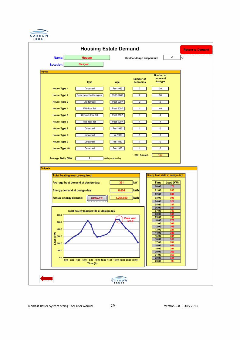
1.2.5 Selecting Options for a Housing Estate
From the Building Heat Demand Inputs sheet, select Embedded monthly demand calculator for the next building to be specified, and click the Proceed button.
In the Select Building Type window, select Housing Estate, and click Continue.
An Embedded demand calculator sheet will open for specifying a Housing Estate.
Outdoor design temperature: input the outdoor design temperature.
Inputs: Up to 10 house specification can be input. For each house specification, the following inputs are required-
Type: Eight types are available; select from the drop-down menu.
Age: Four age bands are available. The age band determines the likely insulation levels, given the building regulations in force at that time.
Number of bedrooms: This input determines the total house floor area, and the DHW requirement.
Number of houses of this type: This specifies the number of houses defined by the inputs for this type.
An average domestic hot water consumption input specifies the kWh/person/day consumed for DHW use.
In a similar manner to other input sheets, a summary of heat demands is displayed, along with a graph and table showing the design day profile. This profile is the aggregate profile for all the houses specified on the housing estate. Click the Update button to ensure that the latest calculated annual results are displayed.
The occupancy profile used for each house is based on that underlying the government’s Standard Assessment Procedure (SAP). To avoid unrealistically high peak loads that would occur if all houses were assumed to follow the exact same heating profile, an element of demand diversity has been introduced; the demands for each hour of the design day have been distributed normally around the demand hour, with the spread increasing with number of houses. The reduction in peak demand for a large (>100) houses is around 33%.
Proceed Save Retrieve
Demand Data Source
Detailed Building Simulation Program
Heat meter measurement
Monthly fuel bill
Embedded monthly demand calculator
Select Building Type
Click here to continue
Building Type
Non-domestic Building
Swimming Pool
Glass House
Housing Estate
Fuel bill
Biomass Boiler System Sizing Tool User Manual 29 Version 6.8 3 July 2013
Name: Outdoor design temperatureoC
Location:
Inputs
House Type 1 Detached Pre 1983
House Type 2 Semi-detached bunglow 1983-2002
House Type 3 Mid-terrace Post 2007
House Type 4 Mid-floor flat Post 2007
House Type 5 Ground-floor flat Post 2007
House Type 6 Top-floor flat Post 2007
House Type 7 Detached Pre 1983
House Type 8 Detached Pre 1983
House Type 9 Detached Pre 1983
House Type 10 Detached Pre 1983
Total houses
2 kWh/person/day
Outputs
Total heating energy required
Average heat demand at design day: kW Time
00:00
Energy demand at design day: kWh 01:00
02:00
Annual energy demand: kWh 03:00
04:00
05:00
06:00
07:00
08:00
09:00
10:00
11:00
12:00
13:00
14:00
15:00
16:00
17:00
18:00
19:00
20:00
21:00
22:00
23:00
100
Average Daily DHW:
0
464
356
337
327
306
282
749
309
304
273
190
Houses
Housing Estate Demand
Number of
bedrooms
3
Number of
houses of
this type
20
AgeType
-3
Glasgow
1 0
1 0
1
531
2 30
2 2
Load (kW)
Hourly load data at design day
1 40
4
1 4
1
245
1 0
361
8,664
1,255,983
178
344
93
369
397
347
531
741
334
338
321
Peak load, 536.9
0.0
100.0
200.0
300.0
400.0
500.0
600.0
0:00 2:00 4:00 6:00 8:00 10:00 12:00 14:00 16:00 18:00 20:00 22:00
Lo
ad
(k
W)
Time (h)
Total hourly load profile at design day
Return to Demand
UPDATE

Biomass Boiler System Sizing Tool User Manual 30 Version 6.8 3 July 2013
When finished, click the “Back” button, or the “Return to Demand” button. The “Select Building Type” window will be displayed. Click the “Back” button again, to return to the Heat Demand Inputs sheet. Click Save to save your data for this building specification, taking care to select the correct building by checking the Building name that you assigned.
The design day heat demand profile for the housing estate will be shown on the graph, along with the profiles for any other building specifications input, and a total profile for all buildings so far specified.
1.2.6 Reviewing and Editing Building Specifications
After entering all Building specifications, the continuous network distribution losses may be entered as a percentage of the peak load (heat demand). This is because the distribution system is sized based on the peak load that it is required to handle, and therefore pipework losses will be a function of the peak load.
To edit the input data for any Building Specification, click on the Retrieve button corresponding to the specified building, and the tool will open the input data sheet corresponding to the selected building, ready for editing. Don’t forget to Save any changes to the correct Building specification after returning to the Building Heat Demand Inputs sheet. Data may be edited at any time by returning to the Demand Module from anywhere within the tool.
Below is an example showing six building specifications. Three are for non-domestic buildings, and one each for a Swimming Pool, Glass house and Housing Estate. District heat system losses have been entered as 1.0% of peak load.

Biomass Boiler System Sizing Tool User Manual 31 Version 6.8 3 July 2013
When satisfied with the building inputs, click on the forward button, or Return to the Main Interface and select Financial Inputs.
Building Heat Demand Inputs
No of building specifications
6 Continuous distribution network power losses: 1.0% of peak load = 17.1 kW
Building name Office DBS
Number of buildings of this type
1
Building name Office MFB
Number of buildings of this type
1
Building name OfficeEMDC
Number of buildings of this type
1
Building name Pool
Number of buildings of this type
1
Building name Conservatory
Number of buildings of this type
1
Building name Housing
Number of buildings of this type
1
Total heating energy required
Average heat demand at design day: kW
Energy demand at design day: kWh
Annual energy demand: kWh
1,223
29,351
3,522,765
Proceed Save Retrieve
Proceed
Proceed
Proceed
Proceed
Proceed Save Retrieve
Save Retrieve
Save Retrieve
Save Retrieve
Save Retrieve
Peak load, 1,813
0.0
200.0
400.0
600.0
800.0
1000.0
1200.0
1400.0
1600.0
1800.0
2000.0
0:00 2:00 4:00 6:00 8:00 10:00 12:00 14:00 16:00 18:00 20:00 22:00
Lo
ad
(kW
)
Time (h)
Hourly load profile at design day
Total demand
Peak load
Of f ice DBS
Of f ice MFB
Of f iceEMDC
Pool
Conservatory
Housing
Return to Main Interface
Demand Data Source
Detailed Building Simulation Program
Heat meter measurement
Monthly fuel bill
Embedded demand calculator
Demand Data Source
Detailed Building Simulation Program
Heat meter measurement
Monthly fuel bill
Embedded monthly demand calculator
Demand Data Source
Detailed Building Simulation Program
Heat meter measurement
Monthly fuel bill
Embedded monthly demand calculator
Demand Data Source
Detailed Building Simulation Program
Heat meter measurement
Monthly fuel bill
Embedded monthly demand calculator
Demand Data Source
Detailed Building Simulation Program
Heat meter measurement
Monthly fuel bill
Embedded monthly demand calculator
Demand Data Source
Detailed Building Simulation Program
Heat meter measurement
Monthly fuel bill
Embedded monthly demand calculator
Fuel bill
Fuel bill
Fuel bill
Fuel bill
Fuel bill
Fuel bill

Biomass Boiler System Sizing Tool User Manual 32 Version 6.8 3 July 2013
1.3 Financial Inputs
The financial input page allows the user to input non-biomass system and other project specific capital cost information, for example, grants and annual inflation rates.
Enter Start Year for Project: The year entered here is the base year for Net Present Value (NPV) and Internal Rate of Return (IRR) in the report.
Buffer Vessel/Thermal Storage Cost: An analysis of buffer vessel and thermal store costs carried out for the Carbon Trust produced a mean cost of thermal storage of £1.10 per litre. However, as considerable variations in the cost of thermal storage are possible, the user is able to insert their own figure here.
Non-Biomass System Capital Cost: The costs of other elements of a new system can be included here, e.g. district heating mains or the conversion of buildings to wet heating.
Capital Grant: Any available capital grant should be input here. A capital grant from a public sector source is mutually exclusive with the Renewable Heat Incentive. Should the user wish to accept a grant from a public sector source, after entering the value of the grant the user should click on 'View and adjust RHI rates' and set the User Defined rates in all of the User Defined cells to zero.
Enhanced Capital Allowance: If the project is eligible for an Enhanced Capital allowance (ECA) an estimate of that should be inserted here.
Contingency Sum: If desired, a contingency capital cost can be input here.
Renewable Heat Incentive: The Renewable Heat Incentive (RHI) subsidy was introduced on March 2011, and is applicable to all new installations. The tariffs used in the tool are as published in the RHI document at www.decc.gov.uk/rhi. The tool automatically calculates the positive contribution to cash flow, year on year, as a result of receipt of the RHI, based on the boiler size and annual heat demand calculated by the tool. The RHI rates will be inflated annually by OFGEM based on the Retail Price Index (RPI), and the user should check that the current rates are
being used in the tool. The user can check that the RHI rates are up-to-date by clicking on “View and adjust RHI rates”. The user can define new rates if necessary, or, if disqualified from receipt of RHI (e.g. due to receipt of a capital grant from a public sector source), set the values to zero.
Specify Relevant Financial Parameters
Enter Start Year for Project 2012
Buffer Vessel/Thermal Storage Cost 1.10 £/litre
Non-Biomass System Capital Cost 100,000 £
Capital Grant (see section 1.3 of User Manual) £
Enhanced Capital Allowance £
Contingency Sum £
Renewable Heat Incentive
Annual Maintenance Cost3.0%
of capital cost of boiler
+ feed mechanism
Annual Insurance Cost 1.0% of total capital cost
Saving from Carbon Reduction Commitment 0.00 £ per tonne CO2 saved
Discount Rate 8.0% for NPV Calculation
Reference Fuel Cost Inflation Rate 5.0%
Biomass Fuel Cost Inflation Rate 1.0%
Auxiliary Fuel Cost Inflation Rate 5.0%
Annual Maintenance Cost Inflation Rate 1.0%
Annual Insurance Cost Inflation Rate 1.0%
€/£ exchange rate 1.12
RPI Inflation Rate 1.0%
View and adjust RHI rates

Biomass Boiler System Sizing Tool User Manual 33 Version 6.8 3 July 2013
Annual Maintenance Cost: Insert the annual maintenance cost of the biomass boiler and fuel handling system as advised by the biomass boiler supplier. This figure is usually in the range 1% - 4% of the capital cost of the biomass boiler and fuel handling system.
Annual Insurance Cost: Additional insurance is frequently required for a biomass system and a figure, expressed as a percentage of the total capital cost, can be inserted here.
Saving from Carbon Reduction Commitment: This figure represents the avoided cost of CO2 saved under the scheme. Currently the figure is £12 per tonne of CO2.
Discount Rate: This is the discount rate required for the NPV calculation.
Reference Fuel Cost Inflation Rate, Biomass Fuel Cost Inflation Rate, Auxiliary Fuel Cost Inflation Rate, Annual Maintenance Cost Inflation Rate and Annual Insurance Cost Inflation Rate: These cells allow the user to input annual inflation rates for all these costs, the data being used in the IRR and NPV calculations for the report.
€/£ Exchange Rate: The algorithm used to calculate biomass boiler system costs requires the current exchange rate to be input.
RPI Inflation Rate: The renewable heat incentive rates are expected to increase in line with the Retail Price Index. An estimate of RPI inflation rate should be inserted to cover the duration of the project payback period.
1.4 Biomass Fuel Type The biomass fuel modules comprise:
• Woodchip fuel data input sheet
• Wood pellet fuel data input sheet The fuel type is selected either by proceeding directly from the main interface sheet to the Biomass Fuel Module, which brings up the screen shown below, or on the Biomass Boiler System Sizing sheet: selecting the fuel type in one location alters the selection in the other location.
Select Biomass Fuel Type
Click here to continue
Biomass Type
Wood Chip
Wood Pellet

Biomass Boiler System Sizing Tool User Manual 34 Version 6.8 3 July 2013
1.4.1 Fuel Data Input - Woodchip
The following have drop-down boxes with selections to be made:
Moisture content: Select the desired fuel moisture content Kind of Wood: Select hardwood or softwood Ash Content: Select the fuel’s ash content as advised by the fuel supplier Fuel Price: Select the fuel price per tonne, per tonne delivered or per kWh
A warning will be displayed if the fuel moisture content is 40% or higher.
Click the heading box (shaded orange) and a menu will appear. If fuel price is inclusive of delivery select “Price per tonne delivered” or “Price per kWh”. If the fuel price is exclusive of delivery select “Price per tonne” and the transportation entries boxes will appear; insert a price per tonne, a transportation cost per tonne per mile and the distance from the fuel supplier. Note that fuel prices here (and throughout the tool) are specified in pounds (not pence).
Default values for the net calorific value of dry wood and dry bulk density are used in the calculations. These values can be overwritten by selecting Kind of Wood as “Other”, and inserting values in the areas below the main fuel input box.
The Tool allows for the comparison of fuel from up to 3 different suppliers (or 3 types of fuel from one supplier), shown as Woodchip 1, Woodchip 2 & Woodchip 3. The Woodchip 1 selection is in bold type to remind the user that it is the values entered in this line which are used in subsequent fuel use and fuel cost calculations.
Fuel Data - Woodchip
as
receivedkg/m3 kWh/m3 kWh/kg
Woodchip1 M30 Soft Wood 1.05 279 945 3.4 95
30
Woodchip2 M30 Soft Wood 1.05 279 945 3.4 110
30
Woodchip3 M40 Soft Wood 0.9 325 914 2.8 105
40
*The elevated moisture content may cause storage problems - decompositionThe values for "woodchip 1" are used in subsequent calculations and the financial analysis
Soft Wood - 18.5 Hard Wood - 19.5 Soft Wood - 195 Hard Wood - 260
Woodchip1 Woodchip2 Woodchip2 WoodChip3
14.00 14.00 250 250
*When dealing with the fuel supplier, following the CEN/TS 14961:2005, the specifications of the fuel properties are given as below
M20 20 A0.7 Ash content ≤ 0.7% 0.7
M30 30 A1.5 Ash content ≤ 1.5% 1.5
M40 40 A3.0 Ash content ≤ 3.0% 3
M55 55 6
M65 65 10
NOTES: Fuel storage
can be sized after sizing
the boiler.
0.028
Moisture
content*Kind of wood
Ash content (%) Fuel density Total cost
dry basis MJ/kg £ per kWh
Net Calorific value Price per
tonne
delivered
Transport cost
per tonne per
mile (£)
Distance
(Miles)
A1.5 12.2
1.5
0.032
1.5
A1.5 12.2
Suitable for storage
0.037
1.5
A1.5 10.1
Moisture ≤ 40%
Limited for storageMoisture ≤ 55%
Moisture ≤ 65%
Moisture (M) Ash content (dry basis)
Moisture ≤ 20% Dried
Moisture ≤ 30%
Source: Smith, K.R.; Kaltschmitt, M.; Thrän, D. 2001 "Renewable Energy from
Biomass"
Woodchip1
Source:UBET Unified Bioenergy Terminology
Default net calorific value (LHV) for dry wood taken is (MJ/kg) Default dry bulk density (kg/m3)
Other Values Other Values
WoodChip3
14.00 2500.000
0.010
0.020
0.030
0.040
Woodchip1 Woodchip2 Woodchip3
Total Cost (£ per kWh)
Return to Main Interface

Biomass Boiler System Sizing Tool User Manual 35 Version 6.8 3 July 2013
1.4.2 Fuel Data Input – Wood Pellets
The following have drop-down boxes with selections to be made:
Moisture content: Select the desired fuel moisture content Ash Content: Select the fuel’s ash content as advised by the fuel supplier
Insert a delivered price per tonne or per kWh (click on the orange box to change between tonnes and kWh).
Default values for the net calorific value of dry wood and dry bulk density are used in the calculations. These are the values published in “Physical Characterisation and chemical composition of densified biomass fuels with regard to their combustion behaviour.” Published in: Proceedings of the 1st World Conference on Pellets. These values can be overwritten in the areas below the main fuel input box. Simply type in your own values in the white boxes, and they will be used in preference to the defaults.
The Tool allows for the comparison of fuel from up to 3 different suppliers (or 3 types of fuel from one supplier), shown as Pellet 1, Pellet 2 & Pellet 3. The Pellet 1 selection is in bold type to remind the user that it is the values entered in this line which are used in subsequent fuel use and fuel cost calculations.

Biomass Boiler System Sizing Tool User Manual 36 Version 6.8 3 July 2013
1.5 Biomass Boiler Sizing
The Biomass Boiler Module is at the heart of the software. It is an interactive module allowing the user to assess system performance against different fuel types and two different operating strategies. The core of the module is a Macro which calculates the boiler, auxiliary boiler and buffer vessel or thermal storage sizes, displaying the results graphically for the user to examine.
There are six steps involved in boiler system sizing. These are arranged in logical order, but there is nothing to prevent the user skipping a step, or returning to a previous step, especially after the first run through the tool. Make sure however that all input boxes are filled. The six steps are now summarised, and more detailed instructions for entering the required data follow in the next section.
1. Inputs: here the type of biomass boiler, auxiliary boiler and reference boiler are specified, with some parameters on which the sizing will be based. Fuel costs are also specified, so that annual energy costs may be calculated. At this stage, the user selects a system sizing strategy to be evaluated:
• Sizing based on minimum buffer vessel size (for boiler protection)
• Sizing based on optimum boiler and thermal store combination
• Sizing based on optimum boiler and thermal store combination, but with a limit on the maximum thermal store size.
2. Sizing Results Part I: A range of boiler and thermal store sizes are evaluated, and the user can choose a particular size combination, based on capital cost, energy cost, or any other relevant criteria.
The user can then save selected results in a table from which side-by-side comparisons can be made of the key features of each selected option.
3. Thermal Storage Vessel: The dimensions and number of thermal storage vessels can be determined iteratively, taking into account such constraints as boiler house roof height. It is also possible to position the thermal storage vessels outside the boiler house, thereby reducing the cost of additional plant room space. It may be convenient to position the vessel horizontally rather than vertically. By adjusting these dimensions, storage vessel volume can be specified to match the volume required according to the latest size combination selected at the previous step. Note that the dimensions are external dimensions, i.e. for the fully insulated vessel. The annual energy calculations will take account of the heat loss from the storage vessels, and the boiler house capital cost that is calculated later will allow for the additional floor space required to accommodate them, in the case that they are selected to be located internally.
After dimensioning the thermal storage vessel, the user should go back and re-run the strategy. Otherwise, the results in the Sizing Results Part I sheet will not reflect the heat losses and plant room costs associated with the thermal store.
Note that the capacity of vessel required is equal to the sum of the thermal store and minimum buffer vessel calculated by the tool, and displayed in the table in Sizing Results Part 1. If sizing is based on Minimum Buffer Vessel, the user may skip this step, as the heat losses from a well insulated vessel will be negligible, compared to the boiler output. The tool makes a standard allowance for plant room space and cost for a minimum buffer vessel, and ignores any data on this sheet.
4. Capital Costs Specification: Having made a system selection, the user then has an opportunity to view and make changes to the capital costs generated by the tool.
5. Fuel Storage Module: Based on the fuel requirements of the chosen boiler selection, the fuel storage type and size can be determined.

Biomass Boiler System Sizing Tool User Manual 37 Version 6.8 3 July 2013
6. Sizing Results Part II: The final step is to view a summary of the boiler system component sizes and a side-by-side comparison of fuel, electricity and CO2 emissions for the biomass and auxiliary boilers, and the comparative reference boiler.
At this point the user can go back to any stage and revise his assumptions, alter the equipment sizes, or try a different strategy.
In any case, it is advisable to return to step 2: Sizing Results Part I for each strategy run, as some of the data included in the comparison table is affected by the thermal storage inputs, capital cost additions, and fuel storage selection. It is important to reset the required boiler size in the Sizing Results Part I sheet before saving, or re-saving a particular results combination, and reviewing changes to the thermal store size, capital costs and the Sizing Results Part II.
By iterating around this area of the tool, the user should arrive at the optimum solution for a project.
1.5.1 Inputs
Biomass boiler system parameters: Select the features relevant to the boiler type being considered for the installation. It may be necessary to check this information with the manufacturer of the boiler it is proposed to use before selecting the data.
The tool has been designed to guide those who are not familiar with the finer details of biomass boiler systems in the selection of realistic combinations of boiler features. The options now described represent the most commonly encountered combinations of features found on biomass boilers. However, the wide range of types of boiler available from numerous manufacturers mean that a particular combination of features from any given manufacturer may not be selectable.
The first selections in this box are used in the calculation of the minimum buffer vessel size required.
Biomass boiler type: Input the boiler type using the drop-down menu. Stoker Burner, Underfed Stoker or Moving Grate can be selected.
Biomass Boiler System Sizing
Specify biomass boiler system parameters Warning: Flue gas recirculation may be required.
Biomass boiler type
Type of fuel feed mechanism
Level of refractory lining
Reference Boiler Information
Fuel consumption in slumber mode Fuel source
Biomass boiler seasonal efficiency % Unit price £ per litre
Biomass boiler flow temperature oC CO2 Factor (if dif ferent from default value)
Circuit return temperature oC Reference boiler burner type Pressure jet25
Days of operation in a year days
Select biomass boiler system sizing strategy
Seasonal efficiency %
Existing district heating network
Specify the size: litre
Other items
Auxiliary boiler data Unit price for electricity £ per kWh
Is auxiliary boiler required for system backup? Yes 1
Minimum back-up boiler size requirement 500 kW
(Notes: Any auxiliary boiler calculated by this tool will be increased to this capacity.)
Fuel type Gasoil
Unit price 0.60 £ per litre
CO2 Factor (if dif ferent from the default value)
Seasonal efficiency 80 %
Auger
Gasoil
80
Manual
0.60
Stoker Burner
Ignition type
High
Typical
Warning: Manual ignition boilers are usually not suitable to supply summer loads. You
may inspect the Annual Load Duration Curve on the Results Part 1 sheet, and modify
your design to optimise the match between the boiler and summer heat demand.You
may opt to switch off the boiler in summer and meet loads from an alternative heat
source.
90
65
240
60
0.12
10,000
No
Click here to define carbon factor
Click here to define carbon factor
Return to Main Interface
Biomass boiler system inputs
Minimum buffer vessel size
Optimum biomass boiler/thermal store combination
Reference boiler inputs
Limit thermal store size

Biomass Boiler System Sizing Tool User Manual 38 Version 6.8 3 July 2013
Type of fuel feed mechanism: There are two possible selections: Ram Stoker and Auger. If Ram Stoker is selected the fuel feed system will comprise a hydraulic ram with a flap valve or lifting gate between the stoker ram and the boiler. This type of fuel feed can only be selected for a Moving Grate type boiler. It is assumed that for auger-fed Stoker Burner and Moving Grate boilers, the auger is always emptied on boiler shut down. It is permissible to leave the fuel in the feed auger of an Underfed Stoker. Auger can be selected for any boiler type.
Level of refractory lining: A high level of refractory lining is required if the boiler is required to burn wood chips with a high moisture content (>40%). If the boiler has a low level of refractory lining, this may remove the need for a buffer vessel into which heat is dissipated on boiler shut down even though boiler efficiency may be improved by the inclusion of a buffer vessel. Select Yes or No.
Ignition type: Boilers are supplied with either an automatic or a manual ignition system. An automatic ignition system will allow the boiler to turn off when there is no demand, and will automatically relight when heat is required. A manual ignition boiler will reduce the fuel feed rate to a minimum sufficient to keep the fire alight on the grate (slumber, or kindling mode). This means that the boiler is always consuming fuel, even when there is no demand for heat. In general, this type of boiler is unsuitable for meeting summer loads (e.g. DHW only). However, if the user proceeds with this selection, the tool will calculate the resulting total fuel consumption, including that used in slumber mode. Select Automatic or Manual.
Fuel consumption in slumber mode: If a manual boiler has been selected, then this input box appears, allowing the user to select the rate of fuel consumption in slumber (or kindling) mode. Manufacturer’s Data (usually a very low figure) or Typical (a more realistic value based on systems observed in practice). See section 2 of this manual for details of formulae used.
Biomass boiler efficiency: Values from 75% to 92% are selectable.
Biomass boiler flow temperature: Values from 81C to 120C are selectable.
Circuit return temperature: Values from 50C to 81C are selectable.
The user should check that the input data in this section represents a valid boiler specification. Although the tool will usually warn the user if an invalid combination of inputs has been specified, it will not always do so, and erroneous results may appear later on.
Select biomass boiler system sizing strategy: Select Minimum buffer vessel size if a buffer vessel is required to avoid overheating on boiler shut down. Select Optimum biomass boiler / thermal store combination if a thermal store is required to allow a reduction in biomass boiler size. Select Limit thermal store size if a thermal store is required to allow a reduction in biomass boiler size, but there is a space limitation that limits the capacity of the thermal store. A box will appear to allow input of the limiting capacity, in litres.
Auxiliary boiler data: The majority of biomass systems are designed with an auxiliary boiler to meet peak loads. The required data on the auxiliary boiler should be entered at this point.
Is an auxiliary boiler required for system backup?: The auxiliary boiler can also be used to provide up to 100% backup to the biomass system. If Yes is selected Minimum back-up boiler size requirement appears and the user should enter the size of the back-up boiler required. This does not prevent the tool from calculating an auxiliary boiler of larger capacity than that specified here, if the tool determines that this is required. If No is selected there is no requirement to enter a back-up boiler size.
Fuel Type: Select the fuel type to be used for the auxiliary boiler from: Natural Gas; LPG; Gasoil; or Kerosene.
Unit Price: Enter the unit price for the fuel type selected in the units which appear to the right of the box.
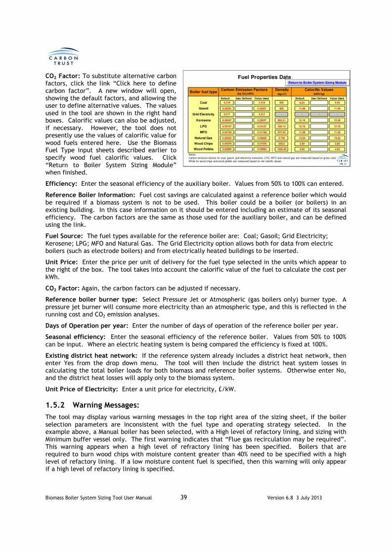
Biomass Boiler System Sizing Tool User Manual 39 Version 6.8 3 July 2013
CO2 Factor: To substitute alternative carbon factors, click the link “Click here to define carbon factor”. A new window will open, showing the default factors, and allowing the user to define alternative values. The values used in the tool are shown in the right hand boxes. Calorific values can also be adjusted, if necessary. However, the tool does not presently use the values of calorific value for wood fuels entered here. Use the Biomass Fuel Type input sheets described earlier to specify wood fuel calorific values. Click “Return to Boiler System Sizing Module” when finished.
Efficiency: Enter the seasonal efficiency of the auxiliary boiler. Values from 50% to 100% can entered.
Reference Boiler Information: Fuel cost savings are calculated against a reference boiler which would be required if a biomass system is not to be used. This boiler could be a boiler (or boilers) in an existing building. In this case information on it should be entered including an estimate of its seasonal efficiency. The carbon factors are the same as those used for the auxiliary boiler, and can be defined using the link.
Fuel Source: The fuel types available for the reference boiler are: Coal; Gasoil; Grid Electricity; Kerosene; LPG; MFO and Natural Gas. The Grid Electricity option allows both for data from electric boilers (such as electrode boilers) and from electrically heated buildings to be inserted.
Unit Price: Enter the price per unit of delivery for the fuel type selected in the units which appear to the right of the box. The tool takes into account the calorific value of the fuel to calculate the cost per kWh.
CO2 Factor: Again, the carbon factors can be adjusted if necessary.
Reference boiler burner type: Select Pressure Jet or Atmospheric (gas boilers only) burner type. A pressure jet burner will consume more electricity than an atmospheric type, and this is reflected in the running cost and CO2 emission analyses.
Days of Operation per year: Enter the number of days of operation of the reference boiler per year.
Seasonal efficiency: Enter the seasonal efficiency of the reference boiler. Values from 50% to 100% can be input. Where an electric heating system is being compared the efficiency is fixed at 100%.
Existing district heat network: If the reference system already includes a district heat network, then enter Yes from the drop down menu. The tool will then include the district heat system losses in calculating the total boiler loads for both biomass and reference boiler systems. Otherwise enter No, and the district heat losses will apply only to the biomass system.
Unit Price of Electricity: Enter a unit price for electricity, £/kW.
1.5.2 Warning Messages:
The tool may display various warning messages in the top right area of the sizing sheet, if the boiler selection parameters are inconsistent with the fuel type and operating strategy selected. In the example above, a Manual boiler has been selected, with a High level of refactory lining, and sizing with Minimum buffer vessel only. The first warning indicates that “Flue gas recirculation may be required”. This warning appears when a high level of refractory lining has been specified. Boilers that are required to burn wood chips with moisture content greater than 40% need to be specified with a high level of refactory lining. If a low moisture content fuel is specified, then this warning will only appear if a high level of refactory lining is specified.
Default User Defined Value Used Default User Defined Value Used
0.318 0.318 850 8.05 8.05
0.32331 0.32331 803 11.89 11.89
0.517 0.517 - - - -
0.29247 0.29247 803.21 12.18 12.18
0.24127 0.24127 508.13 12.75 12.75
0.31108 0.31108 977.50 11.38 11.38
0.20322 0.20322 0.746 13.22 13.22
0.01579 0.01579 250.0 3.89 3.89
0.03895 0.03895 1538.46 4.62 4.62
Notes:
Carbon emission factors for coal, gasoil, grid electricity kerosene, LPG, MFO and natural gas are measured based on gross calorific values;
While for wood chips and wood pellets are measured based on net calorfic values.
Wood Chips
Calorific Values(kg CO2/kWh)
Coal
Gasoil
Kerosene
Grid Electricity
Fuel Properties Data
Density(kg/m3)
Wood Pellets
LPG
MFO
Natural Gas
(kWh/kg)Boiler fuel type
Carbon Emission Factors
Return to Boiler System Sizing Module

Biomass Boiler System Sizing Tool User Manual 40 Version 6.8 3 July 2013
The second warning reminds the user that “Manual ignition boilers are not suitable to supply summer loads.” A manual ignition boiler in slumber mode will consume fuel continuously throughout the summer months, just to service the occasional DHW load. However, the user may continue with this selection, and the tool will calculate fuel use including that consumed during slumber mode in the summer months.
Other warnings may appear, and the table below indicates what causes the warning, and what the user should consider changing to improve the match of the boiler parameters to the other system selections.
Warning Cause Remedy
Flue gas recirculation may be required.
High refactory lining has been specified for a boiler burning dry fuel.
Select Low level of refactory lining, or allow for the additional cost of flue gas recirculation when specifying capital costs.
Automatic ignition not possible, reduce fuel MC to 30% or lower.
Automatic ignition boilers cannot be used with high moisture content wood chips.
Select a manual boiler type, or reduce the fuel moisture content.
Fuel incompatible with boiler. Reduce fuel MC to 30% or lower
High moisture content wood chips are not compatible with Underfed Stokers.
Select a different boiler type, or reduce the fuel moisture content.
Reduce fuel MC to 30% or lower Boilers that are to burn wood chips with high moisture content require a high level of refactory lining.
Select a high level of refactory lining, or reduce the fuel moisture content.
High thermal mass boiler, may be unsuitable to supply summer loads
If a boiler with a high level of refractory lining has no (or minimum) buffer vessel, it will waste a lot of energy during summer operation, as most of the energy stored in the lining on boiler start up will be lost to the flue on shut down.
Select a boiler with a low level of refractory lining, or select an operating strategy that includes a thermal store.
High thermal mass boiler, may be unsuitable to supply summer loads if the thermal store is too small
If a boiler with a high level of refractory lining has too small a thermal store, not all the heat contained within the lining may be recovered on boiler shut down.
Ensure that the thermal store is of sufficient size to recover the heat from the boiler on shut down, or specify a low level of refractory lining.
Manual ignition boilers are usually not suitable to supply summer loads. You may inspect the Annual Load Duration Curve on the Results Part 1 sheet, and modify your design to optimise the match between the boiler and summer heat demand. You may opt to switch off the boiler in summer and meet loads from an alternative heat source.
Self explanatory. Either follow the suggestions given, or change the ignition type to Automatic.
Table 2 Boiler Selection Warning Messages

Biomass Boiler System Sizing Tool User Manual 41 Version 6.8 3 July 2013
The user may choose to ignore any warnings, and continue to size the boiler system based on the chosen selections. The user then needs to analyse the results carefully, and be satisfied that they are not in error.
In the example above, the user may decide to change the boiler type to Automatic, and change the level of refractory lining to Low. The warnings then disappear, as shown below.
The user should now click the red navigation button (forward button) at the bottom right corner (or, return to Main Interface and select Sizing Results Part I.)
Biomass Boiler System Sizing
Specify biomass boiler system parameters 999
Biomass boiler type
Type of fuel feed mechanism
Level of refractory lining
Reference Boiler Information
Fuel consumption in slumber mode Fuel source
Biomass boiler seasonal efficiency % Unit price £ per litre
Biomass boiler flow temperature oC CO2 Factor (if dif ferent from default value)
Circuit return temperature oC Reference boiler burner type Pressure jet25
Days of operation in a year days
Select biomass boiler system sizing strategy
Seasonal efficiency %
Existing district heating network
Specify the size: litre
Other items
Auxiliary boiler data Unit price for electricity £ per kWh
Is auxiliary boiler required for system backup? Yes 1
Minimum back-up boiler size requirement 500 kW
(Notes: Any auxiliary boiler calculated by this tool will be increased to this capacity.)
Fuel type Gasoil
Unit price 0.60 £ per litre
CO2 Factor (if dif ferent from the default value)
Seasonal efficiency 80 %
Auger
Gasoil
80
Automatic
0.60
Stoker Burner
Ignition type
Low
Typical
999
90
65
240
60
0.12
10,000
No
Click here to define carbon factor
Click here to define carbon factor
Return to Main Interface
Biomass boiler system inputs
Minimum buffer vessel size
Optimum biomass boiler/thermal store combination
Reference boiler inputs
Limit thermal store size

Biomass Boiler System Sizing Tool User Manual 42 Version 6.8 3 July 2013
1.5.3 Biomass Boiler System Sizing Results Part I, and Thermal Storage Vessel
1.5.3.1 Sizing with a minimum buffer vessel
The results of running the calculation are shown on the Biomass Boiler System Sizing Results (Part I) page. The three areas of this page are the boiler sizing graph, a boiler size input box, a table where different options can be saved and compared, and an Annual Load Duration Curve. Shown below are example graphs produced with the calculation run for the Minimum Buffer Vessel Option.
At this point the graphs can be examined. The percentage of annual energy from biomass increases as the boiler size increases, so it can be observed that the vast majority of energy can be supplied by a boiler sized at less than half of the peak design day load. The size of the auxiliary boiler decreases as biomass boiler size increases, levelling off if a minimum auxiliary boiler size was specified. The required buffer vessel size increases linearly with biomass boiler size.
The lower graph is an Annual Load Duration Curve. This can be used to assess the suitability of the chosen boiler type and system combination for summer heating. This will be discussed shortly.
Vary biomass boiler rating capacity
Biomass boiler size: 1,411 kW
Percentage of peak load: 80 %
Peak Load at design day (kW): 1,763 kW Sizing Strategy selected:
Biomass boiler size @ 80% of peak load(kW): 1,411 kW
Save the results with different options by pressing the following buttons
Sizing strategy
Percentage of peak load (%) 40 % 34 % 80 %
Biomass boiler capacity (kW) 700 kW 600 kW 115 kW
Minimum buffer vessel size (litre) 0 litre 0 litre 1,000 litre
Thermal store size incl. min buffer vessel (litre) N/A litre 28,100 litre 3,600 litre
Percentage of energy from biomass (%) 90.6 % 89.3 % 99.8 %
Auxiliary boiler size (kW) 1,063 kW 1,163 kW 0 kW
Total system cost (£) 348,900 £ 359,333 £ 88,415 £
Annual fuel cost from biomass (£) 113,983 £ 113,934 £ 6,807 £
Annual fuel cost if use conventional sources (£) 349,461 £ 351,001 £ 12,482 £
Annual cost saving (£) 210,797 £ 208,821 £ 5,656 £
Simple payback (years) 1.7 yrs 1.7 yrs 15.6 yrs
20year IRR N/A % N/A % 33.6 %
20year NPV (£) 5,463,809 £ 5,343,958 £ 190,673 £
Biomass fuel type
Boiler ignition type
Estimated RHI payment (1st Year) 93,405 £ 89,594 £ 9,196 £
Refer to Section 1.5.2 of User Manual for detailed instructions on how
to interpret these results.
Manual Manual Automatic
Wood chips Wood chips Wood pellet
Biomass Boiler System Sizing Results (Part I)
Minimum buffer Optimised Optimised
Option1 Option2
Minimum buffer vessel
Option3
Option 1 Option 2 Option 3
Return to Main Interface
0
500
1,000
1,500
2,000
2,500
3,000
3,500
4,000
4,500
5,000
0%
10%
20%
30%
40%
50%
60%
70%
80%
90%
100%
10% 20% 30% 40% 50% 60% 70%
Vo
lum
e o
f b
uff
er/
Th
erm
al
sto
re (
litr
e)
An
nu
al
% e
nerg
y f
rom
bio
mass
Percentage of peak load (%)
Sizing results
Percentage of energy from biomass
Auxiliary boiler size as a percentage of peak load
Buffer / Thermal store size10 20 30 40 50 60 70 80 %
0%
10%
20%
30%
40%
50%
60%
70%
80%
90%
100%
0 2,000 4,000 6,000 8,000 10,000
Fra
cti
on
al
heati
ng
lo
ad
(%
)
Cumulative hours (hour)
Annual Load Duration CurveFractional Heating Load
Boiler Rating
Boiler Minimum Output

Biomass Boiler System Sizing Tool User Manual 43 Version 6.8 3 July 2013
An operating point can now be chosen to save as an option. If it is decided that 90% of the annual energy should be provided from biomass, from the red curve it can be seen that a biomass boiler sized at 42% of the peak load will provide this. Use the slider to adjust the boiler output (briefly release the slider to see the currently selected percentage of peak load) until a suitable value is selected. It may be that an odd boiler size is displayed (not available from your chosen manufacturer) so adjust the slider until a valid size is shown. This can then be saved as Option 1 by clicking on the Option 1 button, and the left hand side of the page looks like this (the sizing graph does not change).
Now, a summary of the performance of the selected option can be seen in the table. Note that in this case, the thermal store size displays as N/A. This is because we have not yet specified a thermal store, only a minimum buffer vessel.
If the user selects a Manual Ignition boiler, then a buffer vessel is not required, and the tool will enter a value of zero for the buffer vessel size. However, this does not mean that a thermal storage vessel cannot be specified to optimise system efficiency, just that a buffer vessel is not required to protect the boiler against overheating.
Also, observe the Annual Load Duration Curve. This is a cumulative frequency distribution of load, so that any point on the curve of Fractional Heating Load represents the number of hours in the year for which the heating demand will be greater than the value indicated. Also shown are the boiler maximum and minimum firing rates (based on boiler size and turndown ratio). It can be seen that for almost all the year, the load will exceed, or only marginally fall short of the minimum firing rate. This suggests that the choice of system is well suited to summer operation of the system, when only domestic hot water loads and district heat losses, if present, will need to be met. Compare this curve with that shown on the previous page, for a boiler sized at 80% of peak load. This boiler would clearly be oversized for the summer load, even at boiler minimum firing rate, and would likely need to be turned off and the load met using the auxiliary boiler. This becomes more of an issue with a Manual ignition boiler, which runs continually in summer, in slumber mode. If the minimum boiler output cannot be reduced below the load to the right of the Annual Load Duration Curve, when using a Manual ignition boiler, the user should seriously consider changing the selection of ignition type to Automatic.
As a rule of thumb, the user should aim for at least 5,500 hours of annual operation with load above the minimum boiler output.
Vary biomass boiler rating capacity
Biomass boiler size: 750 kW
Percentage of peak load: 43 %
Peak Load at design day (kW): 1,763 kW Sizing Strategy selected:
Biomass boiler size @ 80% of peak load(kW): 1,411 kW
Save the results with different options by pressing the following buttons
Sizing strategy
Percentage of peak load (%) 43 % 34 % 80 %
Biomass boiler capacity (kW) 750 kW 600 kW 115 kW
Minimum buffer vessel size (litre) 2,600 litre 0 litre 1,000 litre
Thermal store size incl. min buffer vessel (litre) N/A litre 28,100 litre 3,600 litre
Percentage of energy from biomass (%) 91.4 % 89.3 % 99.8 %
Auxiliary boiler size (kW) 1,013 kW 1,163 kW 0 kW
Total system cost (£) 477,684 £ 359,333 £ 88,415 £
Annual fuel cost from biomass (£) 114,659 £ 113,934 £ 6,807 £
Annual fuel cost if use conventional sources (£) 375,482 £ 351,001 £ 12,482 £
Annual cost saving (£) 236,615 £ 208,821 £ 5,656 £
Simple payback (years) 2.0 yrs 1.7 yrs 15.6 yrs
20year IRR 741.6 % N/A % 33.6 %
20year NPV (£) 5,795,658 £ 5,343,958 £ 190,673 £
Biomass fuel type
Boiler ignition type
Estimated RHI payment (1st Year) 95,714 £ 89,594 £ 9,196 £
Automatic Manual Automatic
Wood chips Wood chips Wood pellet
Minimum buffer Optimised Optimised
Option1 Option2
Minimum buffer vessel
Option3
Option 1 Option 2 Option 3
10 20 30 40 50 60 70 80 %

Biomass Boiler System Sizing Tool User Manual 44 Version 6.8 3 July 2013
To improve the suitability of a system for summer load operation, the following modifications can be readily investigated using the tool:
• Further reduce boiler size. This is advisable, even at the expense of slightly increased auxiliary boiler use.
• Incorporate a thermal store (see next section) allowing the boiler size (and minimum firing rate) to be reduced, without compromising on maximising utilisation of biomass fuel.
• Choose a boiler with a larger turndown ratio. Stoker burner and underfed stoker boilers with a low level of refractory lining generally have the best turndown ratios.
1.5.3.2 Sizing using a thermal store
To compare the performance of a biomass system designed for optimum performance using a thermal store, the user should press the red navigation button (back button) at the bottom left corner (or, return to Main Interface and select Boiler Sizing Module.) Now the Optimum biomass boiler/thermal store combination should be selected. Press the red navigation button (forward button) at the bottom right corner (or, return to Main Interface and select Sizing Results Part I.)
This returns the user to the Sizing Results Part I sheet, but this time displaying the graphs for the optimum boiler / thermal store solution:
At this point the graphs can again be examined and another operating point chosen to save as an option. It can be seen that 90% of energy from biomass can now be supplied with a boiler sized at 35% of the peak load. The thermal store requirement is, of course, greater than that required for a minimum buffer vessel, and increases in size until a point is reached that the system can meet 100% of demand from biomass. Further increases in boiler size would allow the biomass boiler to meet an increasing proportion of demand directly, so the thermal store size requirement decreases. However, significant issues would now arise due to frequent on/off operation of a very large boiler.
Vary biomass boiler rating capacity
Biomass boiler size: 1,411 kW
Percentage of peak load: 80 %
Peak Load at design day (kW): 1,763 kW Sizing Strategy selected:
Biomass boiler size @ 80% of peak load(kW): 1,411 kW
Save the results with different options by pressing the following buttons
Sizing strategy
Percentage of peak load (%) 43 % 34 % 80 %
Biomass boiler capacity (kW) 750 kW 600 kW 115 kW
Minimum buffer vessel size (litre) 2,600 litre 0 litre 1,000 litre
Thermal store size incl. min buffer vessel (litre) N/A litre 28,100 litre 3,600 litre
Percentage of energy from biomass (%) 91.4 % 89.3 % 99.8 %
Auxiliary boiler size (kW) 1,013 kW 1,163 kW 0 kW
Total system cost (£) 477,684 £ 359,333 £ 88,415 £
Annual fuel cost from biomass (£) 114,659 £ 113,934 £ 6,807 £
Annual fuel cost if use conventional sources (£) 375,482 £ 351,001 £ 12,482 £
Annual cost saving (£) 236,615 £ 208,821 £ 5,656 £
Simple payback (years) 2.0 yrs 1.7 yrs 15.6 yrs
20year IRR 741.6 % N/A % 33.6 %
20year NPV (£) 5,795,658 £ 5,343,958 £ 190,673 £
Biomass fuel type
Boiler ignition type
Estimated RHI payment (1st Year) 95,714 £ 89,594 £ 9,196 £
Increase the thermal store size!
Refer to Section 1.5.2 of User Manual for detailed instructions on how
to interpret these results.
Automatic Manual Automatic
Wood chips Wood chips Wood pellet
Biomass Boiler System Sizing Results (Part I)
Minimum buffer Optimised Optimised
Option1 Option2
Optimum boiler/thermal store
Option3
Option 1 Option 2 Option 3
Return to Main Interface
0
20,000
40,000
60,000
80,000
100,000
120,000
140,000
160,000
0%
10%
20%
30%
40%
50%
60%
70%
80%
90%
100%
10% 20% 30% 40% 50% 60% 70%
Vo
lum
e o
f b
uff
er/
Th
erm
al
sto
re (
litr
e)
An
nu
al
% e
nerg
y f
rom
bio
mass
Percentage of peak load (%)
Sizing results
Percentage of energy from biomass
Auxiliary boiler size as a percentage of peak load
Buffer / Thermal store size10 20 30 40 50 60 70 80 %
0%
10%
20%
30%
40%
50%
60%
70%
80%
90%
100%
0 2,000 4,000 6,000 8,000 10,000
Fra
cti
on
al
heati
ng
lo
ad
(%
)
Cumulative hours (hour)
Annual Load Duration CurveFractional Heating Load
Boiler Rating
Boiler Minimum Output

Biomass Boiler System Sizing Tool User Manual 45 Version 6.8 3 July 2013
If the slide is adjusted so that 34% of peak load appears in the box, and the result saved as Option 2 the left hand side of the page looks like this (again the graphs do not change). Again, 95% of annual energy could be supplied by biomass fuel, but with a much smaller boiler (600kW). A summary of the performance of this option is now displayed in the second column of the table. Note that the Thermal Store size is displayed, and includes the required minimum buffer vessel volume (which has decreased because the boiler is smaller).
However, although the tool has calculated a size for the thermal storage vessel (considerably greater than that required for a minimum buffer vessel) it has not yet taken into account the thermal losses or additional plant room cost to accommodate this vessel. A message usually appears below the graphs to warn the user of this (see above). The user now has to provide some additional information about the thermal storage vessel. Note that the volume includes that required for both the thermal store and the minimum buffer vessel. In practice, these two volumes, though separate from a sizing strategy viewpoint, will be implemented as a single thermal storage system, with appropriate temperature sensors and controls to ensure the buffer vessel function can operate at any time.
At this point, the user should click the forward button, and enter dimensions for the Thermal Storage Vessel. Note that this step is not required when the Minimum Buffer Vessel sizing strategy is being considered.
The number, height and width of the vessel(s) are entered. Also, indicate if the vessel is to be located in the plant room (indoor) or outdoor. This will affect the calculation of heat loss, and the cost of the plant room. Note that the inputs relate to the outer dimensions, including the insulation layer. Input the insulation thickness in mm, and the insulation type.
The aim is to obtain a Specified Tank Water Volume equal to the displayed Required Tank Water Volume. A message is displayed to indicate if the currently specified tank has to be increased, or decreased in size to meet this aim. Note that the water volume required is equal to the sum of the optimum thermal store volume, and the buffer vessel volume. To allow for the fact that vessels may only be manufactured in discrete sizes, the tool allows the vessel to be oversized by up to 15%.
Next, press the back button, and rerun the Optimum Biomass Boiler / Thermal Store strategy (ensure that Optimum biomass / thermal store combination is selected, and click the forward button). Select the 34% (600kW) boiler as before, and resave as option 2. It will be seen that the system cost and annual fuel costs will change, as the cost of the thermal store is now being fully accounted for.
Vary biomass boiler rating capacity
Biomass boiler size: 600 kW
Percentage of peak load: 34 %
Peak Load at design day (kW): 1,763 kW Sizing Strategy selected:
Biomass boiler size @ 80% of peak load(kW): 1,411 kW
Save the results with different options by pressing the following buttons
Sizing strategy
Percentage of peak load (%) 43 % 34 % 80 %
Biomass boiler capacity (kW) 750 kW 600 kW 115 kW
Minimum buffer vessel size (litre) 2,600 litre 2,100 litre 1,000 litre
Thermal store size incl. min buffer vessel (litre) N/A litre 24,900 litre 3,600 litre
Percentage of energy from biomass (%) 91.4 % 87.5 % 99.8 %
Auxiliary boiler size (kW) 1,013 kW 1,163 kW 0 kW
Total system cost (£) 477,684 £ 465,818 £ 88,415 £
Annual fuel cost from biomass (£) 114,659 £ 110,241 £ 6,807 £
Annual fuel cost if use conventional sources (£) 375,482 £ 377,022 £ 12,482 £
Annual cost saving (£) 236,615 £ 231,500 £ 5,656 £
Simple payback (years) 2.0 yrs 2.0 yrs 15.6 yrs
20year IRR 741.6 % 670.9 % 33.6 %
20year NPV (£) 5,795,658 £ 5,595,566 £ 190,673 £
Biomass fuel type
Boiler ignition type
Estimated RHI payment (1st Year) 95,714 £ 89,998 £ 9,196 £
Automatic Automatic Automatic
Wood chips Wood chips Wood pellet
Minimum buffer Optimised Optimised
Option1 Option2
Optimum boiler/thermal store
Option3
Option 1 Option 2 Option 3
10 20 30 40 50 60 70 80 %
Thermal Storage Vessel For Biomass Boiler System
Parameter specification for thermal storage vessels
Number 2
Location Indoor
Position Vertical
Length/Height (l) 4.7 m
Outer diameter of each vessel (do) 2.2 m
Insulation thickness (δ) 100 mm
Insulation type Polyurethane
Volume and heat loss results
Required Tank Volume litre
Specified Tank Water Volume litre
Design Day Heat Loss kWh
Assumptions:
Thermal storage vessel is in cylinder shape.
Heat losses due to radiation and convection are neglected.
24
28274
24900
Return to Main Interface

Biomass Boiler System Sizing Tool User Manual 46 Version 6.8 3 July 2013
At this stage, the Annual Load Duration Curve may be reviewed. The reduction in boiler size will have resulted in fewer hours of operation when the load is less than the minimum boiler size. This particular boiler selection is now very well suited to summer time operation.
1.5.3.3 Reducing the size of the thermal store
The optimum size of thermal store in this case has a total water volume of around 23,000 litres.
Let us suppose that the plant room height is limited, and that we cannot accommodate a vessel capacity greater than 15,000 litres. Press the back button to return to the Biomass Boiler Sizing Sheet, and select the Limit Thermal Store sizing strategy option. Enter a value of 10,000 litres as the maximum thermal store size. Click the forward button to see the results sheet. It can now be seen on the graphs that the thermal store size is limited to 10,000 litres total volume (including the minimum buffer vessel volume).
Vary biomass boiler rating capacity
Biomass boiler size: 430 kW
Percentage of peak load: 36 %
Peak Load at design day (kW): 1,209 kW Sizing Strategy selected:
Biomass boiler size @ 80% of peak load(kW): 967 kW
Save the results with different options by pressing the following buttons
Sizing strategy
Percentage of peak load (%) 36 % 25 % 36 %
Biomass boiler capacity (kW) 430 kW 300 kW 430 kW
Minimum buffer vessel size (litre) 3,500 litre 1,100 litre 1,500 litre
Thermal store size incl. min buffer vessel (litre) N/A litre 14,300 litre 10,000 litre
Percentage of energy from biomass (%) 95.2 % 90.1 % 97.3 %
Auxiliary boiler size (kW) 779 kW 909 kW 779 kW
Total system cost (£) 249,567 £ 216,896 £ 262,913 £
Annual fuel cost from biomass (£) 49,621 £ 47,063 £ 50,801 £
Annual fuel cost if use conventional sources (£) 165,714 £ 166,046 £ 166,046 £
Annual cost saving (£) 110,167 £ 106,707 £ 111,885 £
Simple payback (years) 2.3 yrs 2.0 yrs 2.3 yrs
20year IRR 417.2 % 673.2 % 340.9 %
20year NPV (£) 2,692,791 £ 2,571,928 £ 2,710,728 £
Biomass fuel type
Boiler ignition type
Estimated RHI payment (1st Year) 48,029 £ 43,139 £ 48,093 £
Decrease the thermal store size!
Biomass Boiler System Sizing Results (Part I)
Minimum buffer Optimised Size constrained
Option1 Option2
Limit thermal store size
Option3
Refer to Section 1.5.2 of User Manual for detailed instructions on how
to interpret these results.
Automatic Automatic Automatic
Wood chips Wood chips Wood chips
Option 1 Option 2 Option 3
Return to Main Interface
0
2,000
4,000
6,000
8,000
10,000
12,000
0%
10%
20%
30%
40%
50%
60%
70%
80%
90%
100%
10% 20% 30% 40% 50% 60% 70%
Vo
lum
e o
f b
uff
er/
Th
erm
al
sto
re (
litr
e)
An
nu
al
% e
nerg
y f
rom
bio
mass
Percentage of peak load (%)
Sizing results
Percentage of energy from biomass
Auxiliary boiler size as a percentage of peak load
Buffer / Thermal store size10 20 30 40 50 60 70 80 %
0%
10%
20%
30%
40%
50%
60%
70%
80%
90%
100%
0 70 300 700 1,500 2,500 3,500 4,500 5,500 6,500 7,500 8,500
Fra
cti
on
al
heati
ng
lo
ad
(%
)
Cumulative hours (hour)
Annual Load Duration CurveFractional Heating Load
Boiler Rating
Boiler Minimum Output

Biomass Boiler System Sizing Tool User Manual 47 Version 6.8 3 July 2013
It is no longer possible to meet 95% of the annual energy use from biomass with a 600kW boiler (34% of peak load), due to the thermal store limitation. A boiler sized at 40% of peak load should meet our objective. Select this size (700kW) with the slider, and save as option 3. Note the warning message, informing the user that the thermal storage vessel must be decreased in size. Move forward to the thermal store sizing sheet, and adjust the dimensions to obtain a 15,000 litre store. Click the back button to re-run the “limited thermal store” strategy. Re-adjust the slider to 40% (700kW) and save again as option 3. The costs will now reflect the smaller vessel size.
The user should again review the Annual Load Duration Curve, to ensure that the increase in boiler size has not adversely impacted the suitability of the system for summer operation.
The user could now return to the fuel selection sheet, change the fuel type to Wood Pellets and re-run the calculations (click “Return to Main Interface”, select “Fuel Type Selection”, select “Wood Pellet”, enter cost of wood pellets, click the forward button, select the “Optimum biomass boiler / thermal store combination” sizing strategy, click the forward button, and see the results. If it is desired to examine 95% of energy from biomass using wood pellet fuel, move the slider to 34% (600kW boiler) and save as Option 3 overwriting the previous data in the column. Adjust the thermal store dimensions, and then re-run the strategy. It can be seen that the wood pellet boiler requires a larger buffer vessel, due to the higher calorific value of the fuel, and therefore larger burn-off volume on the grate at boiler shutdown. The payback time is longer, due to the higher cost of wood pellets.
The results displayed in this table are representative of typical results achieved when running the Tool.
Before proceeding, be sure that the boiler size inserted in the Sizing Results Part I sheet above is the size for which a report is required. All subsequent financial calculations will be based on this boiler size.
It is important to note that the calculation macro which generates the graph in the Results Part I sheet inserts a range of values in the boiler size cell, and that this cell will always display the final value of 80% whenever this sheet is selected, because the calculation runs automatically when the sheet is selected. The user needs to change this value to the desired boiler size every time this sheet is selected.
Vary biomass boiler rating capacity
Biomass boiler size: 700 kW
Percentage of peak load: 40 %
Peak Load at design day (kW): 1,763 kW Sizing Strategy selected:
Biomass boiler size @ 80% of peak load(kW): 1,411 kW
Save the results with different options by pressing the following buttons
Sizing strategy
Percentage of peak load (%) 43 % 34 % 40 %
Biomass boiler capacity (kW) 750 kW 600 kW 700 kW
Minimum buffer vessel size (litre) 2,600 litre 2,100 litre 2,500 litre
Thermal store size incl. min buffer vessel (litre) N/A litre 24,900 litre 15,000 litre
Percentage of energy from biomass (%) 91.4 % 87.5 % 91.2 %
Auxiliary boiler size (kW) 1,013 kW 1,163 kW 1,063 kW
Total system cost (£) 477,684 £ 465,818 £ 486,030 £
Annual fuel cost from biomass (£) 114,659 £ 110,241 £ 114,746 £
Annual fuel cost if use conventional sources (£) 375,482 £ 377,022 £ 376,543 £
Annual cost saving (£) 236,615 £ 231,500 £ 236,989 £
Simple payback (years) 2.0 yrs 2.0 yrs 2.1 yrs
20year IRR 741.6 % 670.9 % 614.1 %
20year NPV (£) 5,795,658 £ 5,595,566 £ 5,754,133 £
Biomass fuel type
Boiler ignition type
Estimated RHI payment (1st Year) 95,714 £ 89,998 £ 93,809 £
Automatic Automatic Automatic
Wood chips Wood chips Wood chips
Minimum buffer Optimised Size constrained
Option1 Option2
Limit thermal store size
Option3
Option 1 Option 2 Option 3
10 20 30 40 50 60 70 80 %
Vary biomass boiler rating capacity
Biomass boiler size: 600 kW
Percentage of peak load: 34 %
Peak Load at design day (kW): 1,763 kW Sizing Strategy selected:
Biomass boiler size @ 80% of peak load(kW): 1,411 kW
Save the results with different options by pressing the following buttons
Sizing strategy
Percentage of peak load (%) 43 % 34 % 34 %
Biomass boiler capacity (kW) 750 kW 600 kW 600 kW
Minimum buffer vessel size (litre) 2,600 litre 2,100 litre 5,400 litre
Thermal store size incl. min buffer vessel (litre) N/A litre 24,900 litre 28,200 litre
Percentage of energy from biomass (%) 91.4 % 87.5 % 87.5 %
Auxiliary boiler size (kW) 1,013 kW 1,163 kW 1,163 kW
Total system cost (£) 477,684 £ 465,818 £ 470,383 £
Annual fuel cost from biomass (£) 114,659 £ 110,241 £ 158,960 £
Annual fuel cost if use conventional sources (£) 375,482 £ 377,022 £ 377,042 £
Annual cost saving (£) 236,615 £ 231,500 £ 182,799 £
Simple payback (years) 2.0 yrs 2.0 yrs 2.6 yrs
20year IRR 741.6 % 670.9 % 320.2 %
20year NPV (£) 5,795,658 £ 5,595,566 £ 5,022,630 £
Biomass fuel type
Boiler ignition type
Estimated RHI payment (1st Year) 95,714 £ 89,998 £ 89,998 £
Automatic Automatic Automatic
Wood chips Wood chips Wood pellet
Minimum buffer Optimised Optimised
Option1 Option2
Optimum boiler/thermal store
Option3
Option 1 Option 2 Option 3
10 20 30 40 50 60 70 80 %

Biomass Boiler System Sizing Tool User Manual 48 Version 6.8 3 July 2013
1.6 Capital Costs Specification
It is necessary to confirm the capital cost assumptions, prior to proceeding to the second part of the Sizing Results. From the Thermal Store sheet, click on the lower right red (forward) button to view the Capital Cost Specification sheet.
The system capital cost at the bottom right of the screen is derived from a cost formula prepared for the Carbon Trust from an analysis of a large number of biomass installations, and is described in Part 2 of this manual. The baseline year of this analysis was 2008. The user may wish to inflate capital costs appropriately.
The calculated cost is for a boiler sized as per the figure in the percentage of peak load box on the Results Part I page.
The user may insert alternative costs for each of the items listed down the left hand side. It is designed for installers to insert their own costs to assist with building a quotation, and for other users who may have actual costs for some of these items. A zero cost may be entered in any of the cells, for example, if a piece of equipment is already installed on site.
Where the user has inserted their own costs, the final capital costs column on the right reflects the revised costs for those items and calculates a new system capital cost. This figure then appears in the System Capital Cost box. The Net Capital Cost takes account of additional capital costs, grants and loans on the Financial Inputs sheet.
Biomass Boiler Capital Cost Information
System parts Calculated capital costs User input capital costs Final capital costs
Boiler 116,435 £ £ 116,435 £
Fuel Feed System 15,950 £ £ 15,950 £
Fuel Storage 34,293 £ £ 34,293 £
Boiler House 94,673 £ £ 94,673 £
Buffer/Thermal Storage 31,020 £ £ 31,020 £
Flue 12,760 £ £ 12,760 £
Design, PM & Commissioning 16,748 £ £ 16,748 £
Delivery 5,583 £ £ 5,583 £
Pipework 3,190 £ £ 3,190 £
Electrical & Controls 7,178£ £
7,178£
Auxiliary Boiler fully installed 32,555 £ £ 32,555 £
370,383 £
470,383 £
Capital Costs Specification
Net Capital Cost:
Note: If you have actual costs for any of the items please insert them in the user input capital costs
System Captial Cost:
Return to Main Interface
Biomass Boiler Capital Cost Information
System parts Calculated capital costs User input capital costs Final capital costs
Boiler 116,435 £ 90,000 £ 90,000 £
Fuel Feed System 15,950 £ £ 15,950 £
Fuel Storage 34,293 £ £ 34,293 £
Boiler House 94,673 £ £ 94,673 £
Buffer/Thermal Storage 31,020 £ 25,000 £ 25,000 £
Flue 12,760 £ £ 12,760 £
Design, PM & Commissioning 16,748 £ £ 16,748 £
Delivery 5,583 £ £ 5,583 £
Pipework 3,190 £ £ 3,190 £
Electrical & Controls 7,178£ £
7,178£
Auxiliary Boiler fully installed 32,555 £ £ 32,555 £
337,928 £
437,928 £
Capital Costs Specification
Net Capital Cost:
Note: If you have actual costs for any of the items please insert them in the user input capital costs
System Captial Cost:
Return to Main Interface

Biomass Boiler System Sizing Tool User Manual 49 Version 6.8 3 July 2013
1.7 Biomass Storage
The Biomass Storage sheet allows selections appropriate to the type of fuel selected.
Note: The storage page for pellets is shown. That for wood chips is almost identical.
Biomass type name: Select Woodchip 1, 2 or 3 or Wood Pellet 1, 2 or 3 as appropriate.
How many days storage do you need?: The number of days storage required should be entered. The calculation here assumes that the boiler will be operating continuously for the numbers of days entered. This represents the worst case winter scenario if designing with a minimum buffer vessel or the normal operating scenario if designing with a thermal store. This is explained fully in section 1.5 Biomass Boiler Sizing. The user should check that the fuel storage quantity reported is at least sufficient to accept the fuel supplier’s re-order delivery quantity, plus sufficient emergency capacity in case of delivery delays (due to weather for example).
Storage Option: If Woodchip: Select ‘Square silo sloping floor’ or ‘Walking floor’ if Wood Pellet: Select ‘Square silo sloping floor’, ‘Walking floor’, ‘V-shaped pellet store, or ‘Gravity Hopper’
The slope of a square silo sloping floor must be not more than 15º. A gravity hopper fall angle must be greater than 45º.
Dimensions for the Selected Storage: Enter dimensions for the selected type of storage and compare the calculated Storage Volume with the Required Storage Volume in the box below. Increase or decrease the dimensions of the fuel store until the Storage Volume matches the Required Storage Volume. Messages will appear advising the user to increase or decrease the storage volume as
Biomass Storage
User Inputs
Biomass type name Pellet1
How many days storage do you need at winter design day? 15 days
Storage optionSquare silo sloping
floor
18,000 kWh
Depth/
Height
Width/
DiameterLength
Fall angle
to the horizontal
Exit
diameter
Extractor
angle
Storage
volume
m m m degrees m degrees m 3
Walking floor N/A N/A N/A 0.0
Gravity hopper N/A N/A 0.0
'V' shape pellet store 1 3 4 N/A N/A N/A 3.0
Notes: Please adjust the user inputs for storage dimensions to match the "storage volume" with the "required storage volume".
Suggested Biomass Storage Option
38.6 m3
66.0 tonnes
10,898 £
Storage Capacity
Cost per delivery
Biomass consumption at design day
Dimensions for the Selected Storage
Storage type
Square silo sloping
floor2.4 4.5 N/A 10 44.3
Required Storage Volume
4.5 N/A
Return to Main Interface

Biomass Boiler System Sizing Tool User Manual 50 Version 6.8 3 July 2013
appropriate. The user is of course free to specify a store larger than that calculated by the tool, to allow a reserve in case of winter delivery difficulties, for example.
1.8 Biomass Boiler System Sizing Results Part II
Having selected the system equipment sizes, including the fuel store, and adjusted the capital cost data, the second part of the Sizing Results can now be viewed.
The design day heat demand is shown in the graph (red line), and also the biomass boiler size (blue line), and the likely minimum output, (green line) below which load demand the boiler must switch off.
Biomass boiler size: The recommended boiler size calculated by the software.
Minimum biomass boiler output: Assumes a turndown ratio based on the boiler system selections. For details, see Section 2 of the manual.
Capacity ratio with minimum buffer vessel size: This is a calculated ratio expressed as the capacity of the buffer vessel in litres per kW of biomass boiler rating, and follows logically from the calculation of both biomass boiler and buffer vessel sizes. This figure is included because capacity ratios are frequently quoted by installers and in literature on biomass systems. The capacity of the heating system supplied by the boiler / buffer vessel is not included in this calculation. It is important to note
Biomass boiler size kW Type of storage
Minimum biomass boiler output kW Storage volume m3
Capacity ratio with minimum buffer vessel size litres/kW days
Recommended minimum buffer vessel size litres
Thermal store size required (include minimum buffer vessel size) litres
Annual utilisation factor (as percentage) %
Percentage of heat energy from biomass boiler %
Indicative total capital cost £
Auxiliary boiler size kW
(if minimum buffer vessel size used)
Fuel source selected
Cost (£)
HEATING FUEL
Fuel Wood Pellets Gasoil
Price per kWh (pence per kWh) 4.04 6.28
Annual demand (kWh) 3,599,870 3,599,870
Annual consumption (kWh) 3,938,395 561,443 1,499,946
Annual cost (£) 158,960 35,282 182,799
CO2 factor (tonnes CO2/kWh) 0.000038950 0.00032331
Annual CO2 emitted (tonnes) 153.4 181.5 1604.9
ELECTRICITY
Price per kWh (pence per kWh) 12.0 12.0
Annual consumption (kWh) 25,251 16265 -21,431
Annual cost (£) 3,030 1952 -2,572
CO2 factor (tonnes CO2/kWh) 0.0005170 0.0005170
Annual CO2 emitted (tonnes) 13.1 8.4 -11.1
TOTALS
Annual consumption (kWh) 3,963,645 577,708 1,478,515
Annual cost including RHI (£) 71,992 37,234 270,225
Annual CO2 emitted (tonnes) 166.5 189.9 1583.4
Biomass storage
Square silo sloping floor
15
Biomass Boiler System Sizing Results (Part II)
Biomass boiler system (include thermal store)
600
150 38.6
9 Number of days' storage
under winter design conditions5,400
68.5%
87.5%
437,928
Auxiliary boiler (if applicable)
1163
Gasoil
6.28
5,999,784
GasoilN/A
3,599,870
Energy (kWh)Biomass BoilerAuxiliary Boiler
(if applicable)Reference Boiler
Overall system biomass boiler + auxiliary
boiler
Savings
4,499,838
N/A
28,200
CO2 (tonnes)
109,227
356.4 1939.8
3,599,870
0.00032331
1939.8
377,042
N/A
12.0
N/A
N/A
334.9
194,243
379,452
41,516
4,982
21.5
0.0005170
4,541,353
20,085
2,410
6,019,868
10.4
Peak Load, 1763.21
0.0200.0400.0600.0800.0
1000.01200.01400.01600.01800.02000.0
00:0
0
01:0
0
02:0
0
03:0
0
04:0
0
05:0
0
06:0
0
07:0
0
08:0
0
09:0
0
10:0
0
11:0
0
12:0
0
13:0
0
14:0
0
15:0
0
16:0
0
17:0
0
18:0
0
19:0
0
20:0
0
21:0
0
22:0
0
23:0
0
Po
wer
(kW
)
Time Boiler capacity Boiler min. output Demand at design day Peak Load
Return to Main Interface
Sizing results based on design day load profile
Annual results for biomass boiler system and reference boiler

Biomass Boiler System Sizing Tool User Manual 51 Version 6.8 3 July 2013
that this ratio varies with the temperature difference across the buffer vessel (calculated as the difference between the biomass boiler flow temperature and the circuit return temperature).
Recommended minimum buffer vessel size: Displays the minimum buffer vessel size calculated from the algorithms within the software. These algorithms are described in Part 2 of this manual.
Thermal store size required: If the Optimum sizing strategy was selected, then the calculated volume of thermal storage required is displayed. This figure includes the minimum buffer vessel size shown in the previous box. If the Minimum Buffer Vessel strategy was selected, the box is blank.
Annual utilisation factor: This is the boiler total annual output as a percentage of the number of hours in the year; 8,760hrs, times the boiler capacity.
Percentage of heat energy from biomass boiler: The software calculates the percentage of heat energy which could be provided from the biomass boiler by considering the percentage of the heat load profile which could be met from the biomass system for temperature bins from the outside air temperature entered on the demand sheets up to 14C outside air temperature. A description of this calculation can be found in Part 2 of this manual.
Indicative total capital cost: This figure is obtained from the capital costs calculation.
A summary of the auxiliary boiler size and fuel type, and the fuel store size are provided.
Annual Results for Biomass Boiler System and Reference Boiler: Annual results in terms of energy, costs and CO2 emissions for the operation of the biomass boiler, auxiliary boiler, overall system, and for the reference boiler are tabulated as shown. Note that the annual demands may differ slightly from those shown on the Boiler Heat Demands Inputs sheet. This is due to the adjustment of the annual demands to include losses from the thermal store, and to deduct district heat system losses from the reference boiler demand if the reference system does not include a district heat network. If a manual ignition boiler has been specified, then the fuel consumption during operation in slumber mode is included in the total. The energy and CO2 emissions are displayed for both the fuel use, and for electricity use. The electricity use for the reference boiler is based on this boiler being sized to the peak design day load. This sizing assumption only affects the calculation of electricity consumption.
The total costs of biomass fuel include the effect of the Renewable Heat Incentive (RHI) subsidy. The amount of subsidy is shown in the Report sheet (see next section). The total cost of fuel in this table could be negative if the biomass boiler is operating with a high capacity factor. This is because the total fuel subsidy could be greater than the annual cost of fuel
The energy, cost and CO2 emission savings are also shown.

Biomass Boiler System Sizing Tool User Manual 52 Version 6.8 3 July 2013
1.9 Financial Analysis and Reporting Module The report provides a summary of many of the input values and calculations, and is structured in several sections:
• Title and information on the Project
• Technical Specification
• Energy & CO2 Analysis
• Financial Analysis including a capital cost breakdown, details of grants loans and inflation assumptions, and a Cashflow and Savings analysis for a 20 year period including IRR, NPV and Net Annual savings. Note that these calculations include the income from RHI payments.
Report on Biomass Project for
Project Reference Number
Project name
Site
Prepared by
Company
Date
TECHNICAL SPECIFICATION
Biomass Boiler
Size 110 kW
Type Moving Grate
Ignition Automatic
Efficiency 85%
Fuel feed System Auger
Fuel Wood Pellets
Minimum boiler ouput 37 kW
Buffer Vessel and Thermal Storage
Minimum buffer vessel size 1,100 litres
Capacity ratio 10 litres/kW
Annual energy from biomass 95.9 %
Size of thermal store (incl. min buffer vessel) 23,000 litres
System Temperatures
Flow 95oC
Return 70oC
∆T 25oC
Auxiliary Boiler
Size 377 kW
Fuel Gasoil
Efficiency 80%
Reference Boiler
Fuel Gasoil
Efficiency 60%
Fuel Storage
Number of days storage required 15 days
Storage volume required 6.67 m3
Newtown Council
AB123
New Admin Office
Newtown Redevelopment Area
J. Smith
Ace Heating
10 October 2011
Biomass Report for Newtown Council Page 2
ENERGY & CO2 ANALYSIS
Biomass Boiler System with optimum biomass boiler/thermal store combination
Reference System
Energy Used by Reference Boiler 570,469 kWh
CO2 released by Reference Boiler 182.2 tonnes/year
Biomass System
Energy Used by Biomass Boiler 385,801 kWh
Energy Used by Auxiliary Boiler 22,939 kWh
Annual Biomass Consumed 94 tonnes/year
Annual Savings
Energy Saving 161,728 kWh
CO2 Saving 156.6 tonnes/year
Design Day Load Profile
kW
0
0
0
0
0
429
467
487
447
430
414
396
377
361
357
339
341
348
347
343
339
338
337
20
06:00
05:00
01:00
00:00
07:00
04:00
Time
02:00
03:00
tonnes/year25.6Total CO2 released by Biomass System
(include auxiliary boiler)
23:00
18:00
19:00
22:00
20:00
21:00
08:00
10:00
16:00
17:00
09:00
11:00
12:00
13:00
14:00
15:00

Biomass Boiler System Sizing Tool User Manual 53 Version 6.8 3 July 2013
Figure 1 Financial Analysis and Report
Biomass Report for Newtown Council Page 3
FINANCIAL ANALYSIS
Start Year for Project 2011
Boiler sized to meet 95.9 % energy from biomass
Indicative Range of Capital Costs
Capital Cost 131,727 £
Likely Maximum Capital Cost 171,245 £
Likely Minimum Capital Cost 92,209 £
Capital Cost Breakdown based on Indicative Capital Cost
Boiler 33,926 £
Fuel Feed System 4,647 £
Fuel Storage 9,992 £
Boilerhouse 29,448 £
Buffer Vessel 25,300 £
Flue 3,718 £
Design,PM & Commissioning 4,880 £
Delivery 1,627 £
Pipework 929 £
Electrical & Controls 2,091 £
Auxiliary Boiler 15,168 £
Costs, Grants & Loans
Non-Biomass System Capital Cost 10,000 £
Capital Grant 0 £
Enhanced Capital Allowance 0 £
Contingency Sum 5,000 £
Carbon Trust Zero Interest Loan 0 £
Net Capital Cost 126,727 £
Biomass Fuel Cost (1st Year) 22,883 £
Auxiliary Boiler Fuel Cost (1s t Year) 1,099 £
System Electricity Cost (1s t Year) 1,184 £
Renewable Heat Incentive (1s t Year) 15,291 £
Net Annual Fuel Cost (1s t Year) 9,875
Assumptions
Annual maintenance cost 3.0%
Annual Insurance cost 1.0%
Discount Rate 8.0%
Reference Fuel Cost Inflation Rate 5.0%
Biomass Fuel Cost Inflation Rate 1.0%
Auxiliary Fuel Cost Inflation Rate 5.0%
Annual Maintenance Cost Inflation Rate 1.0%
Annual Insurance Cost Inflation Rate 1.0%
Saving from Carbon Reduction Commitment 12.00 £/tonne CO2 Saved
1,879 £/year
Biomass Report for Newtown Council Page 4
FINANCIAL ANALYSIS - continued
Cashflow & Savings Analysis
13 years
YearCash Flows
(£)
Net Present
value (£)
Net Annual
savings (£)
0 -109,301 37,426
1 36,542 -75,466 39,041
2 38,217 -42,701 40,741
3 39,981 -10,962 42,531
4 41,838 19,790 44,413
5 43,794 49,595 46,394
6 45,852 78,490 48,479
7 48,019 106,508 50,671
8 50,299 133,683 52,978
9 52,698 160,045 55,404
10 55,223 185,624 57,956
11 57,880 210,448 60,640
12 60,675 234,543 63,463
13 63,615 257,934 66,431
14 66,708 280,645 69,553
15 69,962 302,700 72,834
16 73,384 324,120 76,285
17 76,982 344,926 79,913
18 80,767 365,138 83,727
19 84,747 384,775 87,736
20 88,931 403,855 91,951
37%
2%
16%
23%
28%
31%
33%
Simple Payback Period
36%
36%
-22%
35%
Internal Rate
of Return
38%
37%
37%
38%
38%
38%
38%
38%

Biomass Boiler System Sizing Tool User Manual 54 Version 6.8 3 July 2013
2 Underlying Algorithms, Assumptions and Formulae

Biomass Boiler System Sizing Tool User Manual 55 Version 6.8 3 July 2013
2.1 Project Location User Input on Main Interface Page
The user must select a relevant project location, and the available locations are Belfast, Birmingham, Cardiff, Edinburgh, Glasgow, London, Manchester and Plymouth. The project location is used in the calculation of heat demand so the location with the closest climate to that of the actual location should be chosen, this not necessarily being the closest geographical location. The eight locations are those contained in Table 2.3 of CIBSE Guide A 2006 (7th Edition). The frequency of occurrence of daily average temperatures for each location over a range from -3C to +14C was calculated using this data, and a statistical analysis of annual temperature data.
2.2 Demand Module
2.2.1 Overview
In order to calculate the size of biomass boiler system components, the daily profile of hourly heat demand for the building has to be estimated, for a design day. Clearly a profile that does not vary much over the 24 hour period will require less thermal storage to meet peak demand, than one that has very large peaks, e.g. on morning start-up, even though the total daily demand may be no greater. The scope for selecting a larger thermal store and smaller boiler will also be strongly influenced by the shape of this profile, as will the sizing of any auxiliary boiler requirement. Similarly, to estimate the annual energy demand of a particular system combination, the hourly profiles of demand at different times of year will be required.
Ideally, the user could input a complete annual profile of hourly load data for the building. This would require some interfacing between this tool, and, for example, dynamic computer modelling and simulation software for determining building heat loads. Such an interface is out of the scope of this tool. A number of alternative, simple, methods for estimating the building heat demands have been incorporated into this tool.
For non-domestic buildings, and for glass houses, these rely on a database of pilot building heat demand profiles, generated by the ESP-r computer modelling and simulation program, and can be used as the basis to estimate the heat demand profile of any building. For non-domestic buildings, the pilot models are based on a 20m x 10m plan building, 8m high. Three levels of thermal mass, three levels of insulation, three levels of glazing, and three intensities of occupation result in 81 combinations. These 81 models were simulated over a range of outside temperatures from -3C to +14C. So, by entering a few building parameters, and an outside air temperature into the tool, the most appropriate pilot building model is identified, and its heat demand profile is accessed from the database. This profile excludes the effects of internal heat gains, hot water demand, and ventilation load above a minimum infiltration level assumed in the model. The pilot building heat demands then have to be scaled, as the actual building heat demand will be greater, or less, than that of the pilot building. In order to generate an estimate of the profile of heat demand for the design day, for example, the actual design day total net heat demand needs to be known, either from measurement, or detailed simulation software, or based on other calculation methods, e.g. using a method similar to BS EN ISO 13790:2008 standard. This net heat demand is then modified by subtracting the actual building internal heat gains, adding the ventilation load, and subtracting the hot water demand. The result is a gross heat demand comparable to that for the pilot building, at the corresponding design outside air temperature. The ratio of the two gross heat demands is a scaling factor, which can then be used to generate a complete hourly profile for the design day.
A similar method is used for glass houses. Four typical glass house types were modelled, with four different internal temperature setpoints. All glass houses have fabric of mainly glass, and there are no significant casual gains due to occupancy. This results in 16 combinations, which were simulated over a range of outside temperatures from -3C to 20C.
For non-domestic buildings and glass houses, the same technique can be applied to other daily heat demands, in order to calculate heat demand for any outdoor air temperature. The frequency of

Biomass Boiler System Sizing Tool User Manual 56 Version 6.8 3 July 2013
occurrence of heat demands at each outdoor air temperature is used to arrive at an annual heat demand estimate. In the case of non-domestic buildings, if the actual annual heat demand is known, then this final heat demand estimate can be scaled as necessary. This allows for differences in assumptions about the number of days of operation for the building, which may be more or less than that assumed in the simulations.
For swimming pools, the fabric loss can be a relatively small component of the heat demand; considerable heat demand also arises due to the ventilation required to maintain acceptable pool hall humidity levels, and pool heating in order to make up the considerable evaporative loss from the exposed pool surface. Simplified profiles of outside air temperature were estimated based on the maximum and minimum outside air temperatures for any given daily mean, for each of the selectable climate locations. The frequency of occurrence of these average outside temperature profiles were then used to estimate hourly fabric and ventilation losses.
For housing estates, ESP-r models of eight typical housing constructions corresponding to four age ranges were constructed. Properties of the houses were selected based on building regulations in force in each age range. Simulations were then carried out on the resulting 32 house models to calculate annual heat demand. The total floor area of each house was adjusted based on number of bedrooms, and the heat demands simply scaled according to the area ratio, compared to the baseline simulations. Occupancy was also based on the number of bedrooms, so that domestic hot water demand could be estimated.
2.2.2 Heat demand calculations for non-domestic buildings
2.2.2.1 Nomenclature
The following nomenclature is used in the subsequent sections: Gross heat demand Heat demand excluding internal heat gains and ventilation load above a
minimum infiltration level. Net heat demand Heat demand after subtracting internal heat gains (people, lights, equipment)
and adding additional ventilation heat load to Gross heat demand. H Heat demand kWh S Scaling factor = Gross heat demand for actual building / Gross heat demand for
pilot building. Ft Number of days for which bin t heat demand data contributes to annual heat
demand. Suffixes: a Relates to auxiliary boiler b Relates to biomass boiler d Relates to design day. e Relates to heat demand profiles generated for a pilot building by ESP-r dynamic simulation. g Relates to internal heat gains. i Relates to heat demand at hour i. j Relates to average heat demand in month j. n Relates to actual building net heat demand. p Relates to annual heat demand estimate, not scaled to account for actual annual heat demand. t Identity of bin, containing heat demand profile for one day, for an average outside temperature
Tt. v Relates to ventilation heat load. y Relates to annual heat demand. w Relates to hot water demand.

Biomass Boiler System Sizing Tool User Manual 57 Version 6.8 3 July 2013
2.2.2.2 Scaling Procedure
Hei Hour Figure 2: Typical ESP-r generated profile Each of the profile generating and annual energy calculation methods depends on a scaling procedure, to convert the ESP-r generated profile into a profile that fits the user’s actual building. First, the total heat demand for the pilot building is calculated as the sum of the hourly demands: ΣHei = Het total heat demand of pilot building.
where Hei gross heat demand of pilot building at hour i. The hourly net heat demand for the actual building at hour I is given by adding the ventilation load, subtracting the internal heat gains and adding the hot water demand to the scaled heat demand for the pilot building: Hni = S x Hei +Hvi – Hgi + Hwi
The total daily demand of the actual building at outside temperature Tt. is: ΣHni = Ht Therefore, Ht = S x Het + ΣHvi – ΣHgi+ ΣHwi So:
� � �� �∑�� ∑�� � ∑��� �
For annual scaling factor calculation (monthly fuel bill, dynamic building simulation and heat meter demand input methods):
�� �����
Where �� � ∑�� � �� � �� ���

Biomass Boiler System Sizing Tool User Manual 58 Version 6.8 3 July 2013
2.2.2.3 Heat demand from building simulation program, or heat meter measurement data
User inputs:
• Design temperature, Td
• Design day heat demand, Hd
• Hourly profile of demand, Hi profile
• Annual heat demand, Hy
• Internal gains and ventilation rates
• Hd and Hy include DHW heat demand.
• Building characteristics for profile selection. In this case the user inputs a profile for the design day, obtained from a building simulation program, or heat meter measurements. This can be used directly for boiler system sizing. The annual demand is then estimated making use of the ESP-r generated profiles for other outside temperatures, and the user input value of annual heat demand. Figure 3 summarises the procedure.
Figure 3 Calculation of demand from building simulation program, or heat meter data.
User input: Td, Hd, Hd
profile, Hy
Internal gains, ventilation
rates. Hj and Hy include DHW heat demand.
Profile for design day
ESP-r generated profiles and total heat demands Het for pilot building for bins
Tmin<Tt<Tmax
Ft = frequency (days)
of bins.
Boiler, storage,
auxiliary sizing
Profiles for all days
(apply S to Het)Tmin<Tt<Tmax
Calculate annual heat demand scaling
factor
Sy = f(Hy, Hp)
Calculate annual
heat demand
Hp = Σ(Het +Hwi-
Hgi+Hvi)x Ft
Calculate design day
scaling factor
S = f(Hd, Hed)
Apply scaling factor.
Calculate boiler,
auxiliary energy demand for all days
Hbt, Hat
Hb = Sy x Hbt x Ft
Ha = Sy x Hat x Ft
Subtract DHW from,
add gains to, and
subtract ventilation load from Hd
Add DHW profile,
subtract gains, and add ventilation load.

Biomass Boiler System Sizing Tool User Manual 59 Version 6.8 3 July 2013
2.2.2.4 Heat demand from fuel bill
User inputs:
• Design temperature, Td
• Average fuel consumption (from bills) on coldest day, Hj
• Average temperature on coldest day Tj
• Annual heat demand, Hy
• Internal gains and ventilation rates
• Hj and Hy include DHW heat demand.
• Building characteristics for profile selection. In this case the user inputs the demand for the coldest day, and the annual heat demand. In the case of fuel bill data, the tool converts the fuel use to a heat demand figure, based on the calorific value of the delivered fuel. In the case of billing data, this data is also adjusted using degree day input to represent a typical year’s data. There are then two steps to arrive at a design day demand profile. The first step is to adjust the coldest day demand to a design day demand. This is done by selecting the corresponding ESP-r data corresponding to the design temperature, and applying the ratio of these demands to the user input data (after adjusting for DHW, internal gains, and ventilation load). The second step is to apply the scaling procedure described above to the ESP-r generated profile to obtain a demand profile for the design day. After calculating the annual energy demand using this scaling factor, a further adjustment is made to take into account the actual building annual energy demand specified by the user. Figure 4 summarises the procedure.
Figure 4: Calculation of demand from fuel bill data.
User input: Td, Hd, Hd
profile, Hy
Internal gains, ventilation
rates. Hj and Hy include DHW heat demand.
Profile for design day
ESP-r generated profiles and total heat demands Het for pilot building for bins Tmin<Tt<Tmax
Ft = frequency (days)
of bins.
Boiler, storage, auxiliary sizing
Profiles for all days(apply S to Het)
Tmin<Tt<Tmax
Calculate annual
heat demand scaling factorSy = f(Hy, Hp)
Calculate annual heat demand
Hp = Σ(Het +Hwi-
Hgi+Hvi)x Ft
Calculate design day scaling factorS = f(Hd, Hed)
Apply scaling factor. Calculate boiler,
auxiliary energy demand for all daysHbt, Hat
Hb = Sy x Hbt x Ft
Ha = Sy x Hat x Ft
Subtract DHW from, add gains to, and subtract ventilation load from Hd
Add DHW profile, subtract gains, and
add ventilation load.

Biomass Boiler System Sizing Tool User Manual 60 Version 6.8 3 July 2013
2.2.2.5 Embedded heat demand calculator – non-domestic buildings
User inputs:
• Information about the building characteristics for profile selection: thermal mass of building, level of insulation, proportion of façade that is glazed, and occupancy period
• Areas and U-values for external walls, roof, floor, windows, doors.
• Glazing properties
• Outdoor design temperature, Td
• Internal gains and ventilation rates In this case, no user demand data is available for the building, so demands are estimated using a method similar to BS EN ISO 13790:2008 standard, with basic building properties specified by the user. This data is then used to scale the ESP-r generated profiles to obtain profiles for the actual building. Figure 5 summarises the procedure.
Figure 5: Calculation of demand using embedded method.

Biomass Boiler System Sizing Tool User Manual 61 Version 6.8 3 July 2013
2.2.2.6 Ground temperature beneath building
The mean annual ground temperature for each climate location is obtained from the NASA climate data available in the RETSCREEN software www.retscreen.net
2.2.3 Embedded heat demand calculator for glasshouses
The process for calculating the heat demand for glass houses is a simplified version of that used for non-domestic buildings, in that internal gains and domestic hot water do not have to be considered. However, full account is taken of fabric and ventilation losses, and solar gains, as described above. The user inputs are:
• Information about the type of glass house for profile selection: small, Victorian, commercial, orangery.
• Indoor design temperature
• Outdoor design temperature, Td
• Areas for glazing, and areas and U-values for areas of any external walls.
• Orientation and shading of glazing
• Ventilation rate
• Irrigation rate: the quantity of irrigation water can be selected. The U-value for horticultural glass is set at 5.9 W/m2K.
The calculation is then carried out similarly to that described above for non-domestic buildings. It is assumed that all irrigation water supplied has to be evaporated, and the latent heat required to achieve this is added to the heat demand.
2.2.4 Embedded heat demand calculator for swimming pools
Ground floor heat loss is calculated according to the method outlined in CIBSE Guide A, equations 3.20 and 3.21, assuming a wall thickness of 250mm, ground thermal conductivity of 1.5 W/mK (clay) and insulation resistance of 3.125 m2K/W.
A simplified outdoor temperature profile is assumed for each outdoor temperature bin used in the embedded tool as described for non-domestic buildings. The profile is of the form:
Ta=f1*Tmin+f2*Tmax
Where f1 and f2 are given by the following table (CIBSE Guide A 1986):
Hour 00 01 02 03 04 05 06 07 08 09 10 11 12 13 14 15 16 17 18 19 20 21 22 23
f1 0.69 0.78 0.85 0.92 0.96 0.99 1.00 0.96 0.85 0.69 0.50 0.31 0.15 0.04 0.00 0.01 0.04 0.08 0.15 0.22 0.31 0.40 0.50 0.60
f2 0.31 0.22 0.15 0.08 0.04 0.01 0.00 0.04 0.15 0.31 0.50 0.69 0.85 0.96 1.00 0.99 0.96 0.92 0.85 0.78 0.69 0.60 0.50 0.40
Table 3 Factors for simplified outside temperature profile

Biomass Boiler System Sizing Tool User Manual 62 Version 6.8 3 July 2013
The frequency distributions of outside air temperature bins for each climate location are used as previously for non-domestic buildings. The values of Tmin and Tmax, which apply to all climates, have been determined for each outside air temperature bin as:
Table 4 Minimum and maximum temperatures for outside temperature bins
Built-in profiles of heat demand are not used, as the dynamic effects are not considered to be of importance, due to dominant high ventilation rates which impose an instantaneous load on the heating system, and the evaporative loss from the pool, which is assumed to be a relatively steady state process. The equation for outside air temperature is:
The saturation vapour pressure at the pool surface is given by:
��� � 610.78�� ������ !." *17.2694) Pa, where tw is pool water temperature in C.
The saturation vapour pressure of the pool hall air is given by:
��# � 610.78�� �$�$�� !." *17.2694) Pa, where ta is pool hall air temperature in C.
The vapour pressure in the pool hall is given by:
�# � ��#%&�/100 Pa where RH is the relative humidity %.
For an occupied pool, the evaporation rate is given by (Biasin & Krumme):
( � 7.88 ∗ 10*+∗�,-�*,.� � 0.059 kg/m2h for an unoccupied pool (uncovered)
( � 0.118 1.5 ∗ 10*1∗�,-�*,.� ∗ 23� kg/m
2h for an occupied pool
Outside Temperature Bin Tmin Tmax
C C C
-3 -5 -1
-2 -4 0
-1 -3.25 1.25
0 -2.25 2.25
1 -1.5 3.5
2 -0.75 4.75
3 0 6
4 1 7
5 1.75 8.25
6 2.5 9.5
7 3.25 10.75
8 4 12
9 4.75 13.25
10 5.5 14.5
11 6.5 15.5
12 7.25 16.75
13 8 18
14 8.5 19.5
15 9.25 20.75

Biomass Boiler System Sizing Tool User Manual 63 Version 6.8 3 July 2013
Efficiency of various methods of heat recovery are as follows:
Heat recovery method Efficiency % Run-around coil �0.00012 ∗ 5#6 � 0.0024 ∗ 5# 0.367 Air to air plate heat exchanger �0.0002 ∗ 5#6 � 0.004 ∗ 5# 0.611 Heat pump dehumidifier 80
Table 5 Heat recovery efficiencies
2.2.5 Embedded heat demand calculator for housing estates
The number of floors, number of bedrooms, occupancy and floor areas of the house models used are shown in the following table. The baseline heat demands for each house type, as calculated by dynamic simulation, are scaled according to the number of bedrooms specified by the user. The number of occupants is always assumed to be one more than the number of bedrooms. The number of occupants is then used to calculate the domestic hot water heat demand. Table 6 Floor areas of house types
Built Form No. of Floors Number of bedrooms
Occupancy Floor area (m2)
Detached 2 3 4 52x2
Semi-detached 2 2 3 45x2
Mid terrace 2 1 2 39x2
Detached bungalow 1 2 3 90
Semi-detached bungalow
1 2 3 90
Flat top 1 2 3 90
Flat mid 1 2 3 90
Flat ground 1 2 3 90
The details of the construction of the house models used to assemble housing estates are shown in the following tables. Table 7 Ventilation rates of house types
Air change rate ach
pre 1983 1
1983-2002 0.7
2003-2007 0.5
post 2007 0.3
Table 8 U-values of house constructions, W/m2K
U-values pre 1983 1983-2002 2003-2007
post 2007
wall 2 0.6 0.31 0.31
roof 2 0.35 0.16 0.14
floor 0.88 0.46 0.25 0.22
glazing 5.6 3.4 2.1 1.7
door 3 3 2 1.7
The heating control is set to turn heating on from 07:00 to 09:00 and from 16:00 to 23:00 each day. The thermostat setpoint is 21C in the living zone, and 18C in the non-living zone.

Biomass Boiler System Sizing Tool User Manual 64 Version 6.8 3 July 2013
The same heating control profile is used in all houses included in the demand calculation. Simply adding the individual contributions from each house’s 24hr demand profile would result in an unrealistically high peak demand. Work by Marks and Stockwell1 suggest a 33% reduction in peak demand in large populations due to demand diversity to be typical. Each hourly demand is modified by spreading the demand over the previous and following hours following a normal distribution, with
standard deviation equal to 2�1.2 � �*2/669� where n is the number of houses.
1 Marks W.L. & Stockwell D.H. Group Heating Schemes – the prediction of boiler heat load allowing for uncertainties in the heat loss terms. Building Serv Eng Res Technol 1980 1: 185

Biomass Boiler System Sizing Tool User Manual 65 Version 6.8 3 July 2013
2.3 Biomass Fuel & Storage Modules
2.3.1 Woodchip Fuels
2.3.1.1 Calorific Value
The formulae for the calorific value of woodchip fuels used in this Tool have been derived from a fuel calculator developed by EVA, the Austrian Energy Agency. The default calorific values for dry wood of 18.5MJ/kg for softwood and 19.5MJ/kg for hardwood are derived from “Renewable Energy from Biomass” by KR Kaltschmitt and M Thrön 2001.
For softwood woodchips the calorific value is CV = (18.5*(100-MC)-2.442*MC)/100 MJ/kg
For hardwood woodchips the calorific value is CV = (19.5*(100- MC)-2.442* MC)/100 MJ/kg
where MC is the fuel moisture content in percent.
The moisture content and ash content range values are derived from CEN/TS 14961:2005.
2.3.1.2 Bulk Density
The default values for dry bulk density of 195kg/m3 for softwood woodchips and 260kg/m3 for hardwood woodchips are derived from UBET Unified Bioenergy Terminology.
For softwood woodchips the bulk density = 195/((100- MC)/100) kg/m3
For hardwood woodchips the bulk density = 260/((100- MC)/100) kg/m3
where MC is the fuel moisture content in percent.
2.3.2 Wood Pellet Fuels
The user can input the calorific value for dry wood pellets for each of Pellet 1,2 & 3 on the Fuel Data –Pellets sheet. The formula for the calorific value of wood pellets is:
CV = (CVDW *(100-MC)-2.442*MC)/100
where CVDW is the calorific value for dry wood inserted by the user (default value 20MJ/kg) and MC is the fuel moisture content in percent.
2.3.3 Biomass Storage
No assumptions have been made in the construction of the Biomass Storage page.

Biomass Boiler System Sizing Tool User Manual 66 Version 6.8 3 July 2013
2.4 Biomass Boiler Module
2.4.1 Boiler Sizing Module
2.4.1.1 Buffer Vessels and Thermal Stores
When the selection of either minimum buffer vessel or optimum boiler/thermal store is made for the sizing strategy, it implies particular hydraulic configurations and control algorithms. In order for the results indicated by the software to be achieved the systems need to be operated as described below. Biomass Boiler and Buffer Vessel
The typical configuration of a biomass boiler and buffer vessel is shown here 2. The software assumes that the buffer vessel contributes to meeting the peak load on start-up, reducing the energy required from an auxiliary boiler. In order for this to happen Pump 2 must be a variable speed pump sized to draw stored hot water from the buffer vessel as well as the boiler on start-up. Once the buffer vessel has depleted the speed of Pump 2 needs to be reduced to match that of Pump 1.
The majority of systems with a buffer vessel are controlled using a simple on/off control strategy using two temperature sensors as shown here. However, some systems use the progressive control described below for systems with thermal stores.
Figure 6: Biomass boiler and buffer vessel piping schematic. Biomass Boiler and Thermal Store
The typical configuration of a biomass boiler and thermal store is shown here. The software assumes that the biomass boiler operates continuously charging the thermal store at times when the output of the biomass boiler exceeds the load demand, typically overnight when there is no demand from a building.
The majority of systems with a thermal store are controlled using a progressive control strategy using several temperature sensors as shown here. Again, once the buffer vessel has depleted the speed of Pump 2 needs to be reduced to match that of Pump 1.
Figure 7: Biomass boiler and thermal store piping schematic.
2 A description of the operation of buffer vessel and thermal storage systems is beyond the scope of this manual.
Biomass Boiler
Pump 1
BufferVessel
Pump 2
BoilerStart Sensor
BoilerStopSensor
VSD
T1
T5
BiomassBoiler
VSDPump 1
Pump 2
TemperatureSensors
T4
ThermalStore
T2
T3

Biomass Boiler System Sizing Tool User Manual 67 Version 6.8 3 July 2013
2.4.1.2 Minimum Buffer Vessel Sizes and Turndown Ratios for Automatic boilers
The following formulae have been calculated from a detailed analysis of the fuel feed systems, grate systems and refractory linings of biomass boilers, and the results produced appear to consistent with the range of values recommended for each type of boiler. There are significant variations in the sizes of buffer vessels recommended by different manufacturers, and the volumes derived from the formulae below should be used as a guide to the size of buffer vessel likely to be required.
A typical fuel feed configuration is a rotary valve followed by up to 1m of feed auger to the grate, and in these cases the fuel content of the auger is taken into account when calculating the buffer vessel size. This is because it is usual to empty the feed auger on cessation of boiler firing to prevent burn-back along the auger on over-fed stokers, whereas for a boiler with an underfed stoker it is often permissible to leave the underfed auger full of fuel because burn-back rarely occurs downwards. Similarly, if a hydraulic ram stoker is used, or a flap valve is located immediately prior to the grate (as can be found on some over-fed stokers), there will be no fuel prior to the grate and the fuel content of the auger can again be ignored.
The size of minimum buffer vessel will also depend on the level of refractory lining.
The YT in the formulae is the temperature difference across the buffer vessel when charging. It is derived in the software by calculating the difference between the Biomass boiler flow temperature and Circuit return temperature which are inputs on the Biomass Boiler System Sizing page. The results from the formulae are in litres per kW of boiler capacity, where V is the volume of buffer vessel capacity required in litres/kW.
Also shown in the table is the typical turndown ratio for each boiler type.
Fuel Boiler type Fuel feed mechanism
Refractory lining
Buffer Vessel Formula (l/kW)
Turndown
Ratio
Wood chips Stoker burner Augur Low V = 89.17YT-1.0031 3.5:1
Wood chips Stoker burner Augur High V = 120.4YT-1.0015 3:1
Wood chips Moving grate Auger Low V = 202.19YT-0.9982 3:1
Wood chips Moving grate Auger High V = 371.06YT-1.0011 2.5:1
Wood chips Moving grate Ram stoker Low V = 158.27YT-0.997 3:1
Wood chips Moving grate Ram stoker High V = 374.1YT-1.0009 2.5:1
Wood chips Underfed stoker Auger Low V = 57.946YT-1.006 3.5:1
Wood chips Underfed stoker Auger High V = 89.17YT-1.0031 3:1
Pellets Stoker burner Augur Low V = 223.46YT-0.9989 4:1
Pellets Stoker burner Augur High V = 255.64YT-1.0002 3.5:1
Pellets Moving grate Auger Low V = 249.53YT-1.001 3:1
Pellets Moving grate Auger High V = 463.45YT-1.0003 2.5:1
Pellets Moving grate Ram stoker Low V = 124.62YT-0.9991 3:1
Pellets Moving grate Ram stoker High V = 338.1YT-0.9989 2.5:1
Pellets Underfed stoker Auger Low V = 57.946YT-1.006 3.5:1
Pellets Underfed stoker Auger High V = 130.27YT-0.9955 3:1
Table 9 Equations for Buffer Vessel Sizing, and Turndown Ratios for Automatic Ignition Boilers

Biomass Boiler System Sizing Tool User Manual 68 Version 6.8 3 July 2013
2.4.1.3 Turndown Ratios for Manual Ignition Boilers
(Buffer vessels are not required for Manual Ignition boilers.)
Fuel Boiler type Fuel feed mechanism
Refractory lining
Turndown Ratio
Wood chips Stoker burner Augur Low 3.5:1
Wood chips Stoker burner Augur High 3:1
Wood chips Moving grate Auger Low 3:1 Wood chips Moving grate Auger High 2.5:1 (2:1 for MC>40%) Wood chips Moving grate Ram stoker Low 3:1 Wood chips Moving grate Ram stoker High 2.5:1 (2:1 for MC>40%) Wood chips Underfed stoker Auger Low 3.5:1 Wood chips Underfed stoker Auger High 3:1 Pellets Stoker burner Augur Low 4:1
Pellets Stoker burner Augur High 3.5:1 Pellets Moving grate Auger Low 3:1 Pellets Moving grate Auger High 2.5:1 Pellets Moving grate Ram stoker Low 3:1 Pellets Moving grate Ram stoker High 2.5:1 Pellets Underfed stoker Auger Low 3.5:1 Pellets Underfed stoker Auger High 3:1
Table 10 Turndown Ratios for Manual Ignition Boilers
2.4.1.4 Fuel Consumption of Manual Boilers in Slumber (Kindling) Mode
When there is no heat demand, a manual boiler will reduce its firing rate to a low level, sufficient to keep the boiler alight. This is termed Slumber, or Kindling mode. Manufacturers typically claim that their boiler will consume only 0.5% of the boiler power rating whilst in slumber mode. Practical experience suggests that boilers consume rather more than this, typically as shown in this graph.
If the user selects Manufacturer’s data in the slumber mode input box, the tool will assume slumber mode fuel consumption of 0.5% of the boiler power rating. If the user selects Typical, then the tool will select a value according to this graph.
Table 11 Typical Slumber Mode Fuel Consumption
0
0.5
1
1.5
2
2.5
3
3.5
4
4.5
5
0 500 1,000 1,500 2,000 2,500 3,000
% o
f b
oil
er
po
we
r ra
tin
g
Boiler size, kW
Slumber mode fuel consumption

Biomass Boiler System Sizing Tool User Manual 69 Version 6.8 3 July 2013
2.4.1.5 CO2 Emission Factors and Calorific Values of Fuels
The tool uses emission factors and calorific values approved by the Carbon Trust. These will be updated periodically. The following are the values used in this version of the tool. The fossil fuel values are based on the gross (higher) calorific values, whereas the wood chip and wood pellet values are based on the net (lower) calorific values. Note that the tool does not currently use the calorific values listed here for wood fuels. If the user wants to use these values, they should enter them directly on the Biomass Fuel Input sheets.
Fuel
CO2 Factor kg CO2/kWh
Density kg/m
3
Net CV kWh/kg
Coal 0.318 850 8.05
Gasoil 0.32231 803 11.89
Grid Electricity 0.517 - -
Kerosene 0.29247 803.21 12.18
LPG 0.24127 508.13 12.75
MFO 0.31108 977.5 11.38
Natural Gas 0.20322 0.746 13.22
Wood Chips 0.01579 250 3.89
Wood Pellets 0.03895 1,538.46 4.62
Table 12: Calorific values and CO2 emissions of fuels.
2.4.1.6 Pound Sterling/Euro Exchange Rate
See Section 2.5.1.1.
2.4.2 Calculation of the Percentage of Heat Energy from Biomass
Figure 8 indicates a typical design day heat demand profile, showing a biomass boiler that has been sized to meet a fraction of the peak heat demand. Biomass boiler, auxiliary boiler, and buffer vessel / thermal store are all sized based on the design day demand profile. This profile is calculated based on the data supplied in the Demand Module. See section 2.2 Demand Module for a detailed description of Demand Module calculation processes.
The annual heat demand met by the biomass and by the auxiliary boilers is calculated by considering the heat demand profiles for other outside temperatures. These are calculated based on the data supplied in the demand module. Each resulting demand profile is associated with a frequency of occurrence (number of days), depending on the location selected on the Main Interface. These calculations of annual heat demands depend on the system selections made in the Sizing Module.
Figure 8: Typical design day head demand profile, and boiler size.
kW
Hours
Heat
demand Boiler
size

Biomass Boiler System Sizing Tool User Manual 70 Version 6.8 3 July 2013
There are two cases to consider:
a. The user has requested that the tool calculate the minimum buffer vessel size required for boiler protection;
b. The user has requested that the tool calculate optimum biomass boiler and thermal store sizes.
The thermal store is used to allow a given biomass boiler to meet a larger proportion of the annual heat demand.
2.4.2.1 Calculation of the Percentage of Heat Energy from Biomass for the Minimum Buffer
Vessel Size and Auxiliary Boiler Sizing
In this case the tool calculates a buffer vessel size as described in Part 2 – Minimum Buffer Vessel Size. The auxiliary boiler size is then the difference between the biomass boiler capacity and the peak heat demand. The heat demand supplied by the biomass boiler is simply the total heat demand that is less than or equal to the boiler capacity (green shaded area) plus the heat required to top up the buffer vessel (on boiler shut down). The excess demand is met by the auxiliary boiler (red shaded area in the diagram on the previous page), less the capacity of the buffer vessel, which is assumed to meet part of the initial load on boiler start up. The tool repeats this calculation for each of the outside temperature profile bins and then multiplies the heat demands met by biomass boiler and by auxiliary boiler for each bin by the frequency of occurrence of the outside temperature for each bin.
2.4.2.2 Calculation of the Percentage of Heat Energy from Biomass for the Optimum
Combination of Biomass Boiler and Thermal Store, and Auxiliary Boiler Sizing
In this case the tool calculates an optimum combination of biomass boiler and thermal store for a range of biomass boiler sizes that meet from 10% up to 80% of the design day peak demand. The calculation is automatic, and the user can then inspect the graphical output to examine particular combinations of interest in more detail.
For each boiler size, the tool adds up, for each hour, the difference between the boiler capacity and the heat demand, for periods when the boiler capacity exceeds the heat demand (blue shaded area). This represents the residual boiler capacity available to charge up a thermal store. The tool also calculates the difference between the boiler capacity and the heat demand when the boiler capacity is less than the heat demand (red shaded area on diagram on previous page). There are then two possibilities:
1. If the boiler capacity excess is less than the excess heat demand, then the thermal store size will be equal to the boiler capacity excess. In that case, when system starts up, the thermal store will meet the excess demand until the thermal store is exhausted (orange shaded area in Figure 9). There will be insufficient capacity of thermal storage to meet all of the excess demand, so an auxiliary boiler will be required, with its size set to meet the highest excess load after the thermal store is exhausted. The remaining excess demand will then be met by this auxiliary boiler.
Figure 9: Sizing of thermal store and auxiliary boiler.
kW
Hours
Heat
demand
Boiler
sizeDemand met
by auxiliary
boiler
Demand
met by
thermal
store

Biomass Boiler System Sizing Tool User Manual 71 Version 6.8 3 July 2013
2. If the boiler capacity excess is greater than the excess heat demand, then the thermal store size
will be equal to the excess heat demand. In that case, the combination of biomass boiler and thermal store will be sufficient to meet the demand at all times, and an auxiliary boiler is not required.
In both these cases, the tool repeats the calculation for each of the outside temperature profile bins and then multiplies the heat demands met by biomass boiler and by auxiliary boiler for each bin by the frequency of occurrence of the outside temperature for each bin.
Note that the user may request that an auxiliary boiler is required for back-up purposes. This option will not affect the calculations described above.
2.4.3 Biomass Boiler Results for Different Options
2.4.3.1 Creation of Sizing Graph
The graph has been created using a macro which inputs values of biomass boiler size as a percentage of peak load in 5% steps from 10% to 80%. The resulting values are then plotted for:
• Percentage of energy from biomass
• Auxiliary boiler size
• Buffer vessel or thermal storage size (including the buffer vessel volume)
2.4.3.2 Creation of Annual Load Duration Curve
The Annual Load Duration Curve equation is given by Sochinsky as:
Heat load that is exceeded for T hours in year � 1 � �1 � :(;<� ∗ 5=>?=>@AB?=>
where: βmin = ratio of minimum load (DHW + district heat losses) to the peak load, Βm = average load as fraction of maximum load (utilisation factor) The graph is only an approximate representation of the load data entered into the tool. It is a simplified illustration of how load is typically distributed over the year, so that the user can judge the likely performance issues that will result if a boiler is too large to meet the lower loads in summer.
2.5 Financial Analysis & Reporting
2.5.1 Financial Analysis
2.5.1.1 Pound Sterling/Euro Exchange Rate
The vast majority of biomass boilers, their ancillary equipment and fuel feed systems are manufactured in Europe and priced in Euros. At the time the biomass cost formula was derived, and for the preceding several years when the installations analysed to produce the formula were costed, the £/€ exchange rate was in the region of €1.40 to the £. The global financial crisis of 2008/2009 saw this exchange rate drop sharply, so the user has the option to insert a current exchange rate in the Additional data input box on the Biomass Boiler System Sizing page. The biomass boiler system cost formula has been modified on the basis that 50% of the overall system capital cost is from Europe.

Biomass Boiler System Sizing Tool User Manual 72 Version 6.8 3 July 2013
2.5.1.2 Biomass Boiler System Cost Formula
The formula used to calculate the total cost of a biomass system was derived from an analysis of a large number of installed systems ranging in size from 50kW to 3MW. The original formula derived for the Carbon Trust publication CTG012 - Biomass heating: A practical guide for potential users has been modified as described above. The original formula produced the curve shown in Figure 10 which is included within CTG012.
Figure 10: Capital cost ranges for a biomass boiler system.
The modified overall biomass system cost formula used in the software is:
The cost of a biomass system = (BR x 2535.2 x BR-0.2731) x (1 + (1.4 – ER)/2)
where BR = the calculated biomass boiler rating in kW and ER = the £/€ exchange rate input on the Biomass Boiler System Sizing page This formula will be updated by the Carbon Trust at regular intervals.

Biomass Boiler System Sizing Tool User Manual 73 Version 6.8 3 July 2013
The breakdown of costs, prepared for the Carbon Trust, and displayed on the Financial Analysis page and in the Report is as shown in Table 13.
Boiler 39.0%
Fuel Feed System 5.3%
Fuel Storage 11.5%
Boilerhouse 27.3%
Buffer Vessel* 1.6%
Flue 4.3%
Design, Project Management & Commissioning 5.6%
Delivery 1.9%
Pipework 1.1%
Electrical & Control 2.4%
Total 100.0% Table 13: Biomass boiler system cost breakdown.
*In the current version of the tool, the 1.6% proportion of cost for buffer vessel is not included in the system cost. The tool substitutes a cost based on the cost per litre for Buffer Vessel / Thermal Storage on the Financial Inputs sheet, and for thermal stores, adds a cost to account for additional plant room space required based on the floor area derived from the Thermal Store module; see next section.
2.5.1.3 Heat loss calculation, and plant room space requirement.
In the Thermal Storage Vessel for Biomass Boiler System sheet, the user inputs dimensions for the thermal store. These are outer dimensions, including insulation. Based on these inputs the tool calculates the total heat loss from the stored water to ambient, assuming the thermal store temperature to be the maximum boiler output temperature, and the ambient temperature to be either the external temperature, or the external temperature plus ten degrees C, depending on the location of the thermal store; outdoor or indoor. In the indoor case, the minimum plant room temperature is assumed to be 5C.
The heat loss for each vessel is given by: CD � E∙3∙�G@*GH�IH 6J ∙K2LMHM@ N
Where, Qj: heat loss of the j
th thermal store (in W) λ: thermal conductivity of insulation material (in W/m.K) A: surface area of thermal store (in m2) Ti: average temperature of water temperature inside thermal store (in degC) To: average temperature outside thermal store (in degC) Di: inner diameter of thermal store (in m) Do: outer diameter of thermal store (in m)
The plant space requirement for an indoor vessel is based on an area of plan dimensions equal to a square with sides equal to the vessel diameter plus 0.5m for a vertical vessel, or a rectangle with sides equal to the vessel length plus 0.5m, and the diameter plus 0.5m for a horizontal vessel. This area is costed at £850 / m2 and this cost is included in the total system cost.
The values of thermal conductivity for the insulation types are:
Polyurethane 0.02 W/mK Rockwool 0.045 W/mK Glasswool 0.04 W/mK
The above calculations are only carried out for Thermal Stores. Minimum Buffer Vessel sizes are relatively small, so heat losses are negligible, compared to the boiler output.

Biomass Boiler System Sizing Tool User Manual 74 Version 6.8 3 July 2013
2.5.1.4 Calculation of Fossil Fuel Boiler Costs
The capital costs of auxiliary and back-up boilers are calculated from a series of formulae. A leading European boiler manufacturer provided costs for both natural gas and gas-oil fired boilers in the size range 70kW to 3MW (6 boilers in the size range for each fuel). These costs were then increased by 25% to allow for the cost of a flue, and the resulting figures were doubled to represent installed boiler costs. The resulting formulae are shown in Table 14.
Installed Cost (IC) (£)
Natural gas boilers
70kW – 890kW IC = 2,000 + 34.21 x BR
890kW – 3MW IC = 16,000 + 18.82 x BR
Gasoil boilers
70kW – 800kW IC = 5,000 + 22.52 x BR
800kW – 3MW IC = 9,000 + 17.14 x BR
Table 14: Auxiliary and back up boiler cost calculation.

Biomass Boiler System Sizing Tool User Manual 75 Version 6.8 3 July 2013
2.5.1.5 Calculation of Electrical Consumption of Boiler Ancillary Equipment
Biomass and fossil fuel boilers require several items of ancillary equipment, for example, burners, pumps, fuel feed mechanisms, flue particulate removal cyclones. The tool includes an estimation of the energy consumption of these items according to boiler type, for the biomass, auxiliary, and reference boilers. The CO2 emissions due to these consumptions are also accounted for. The table below shows the main assumptions used in carrying out these calculations.
Ancillary Item Electrical Consumption as a Percentage of
Boiler Thermal Rating Pth
Notes
Fuel Store Type & Outfeed Mechanisms Walking Floor (Pushrod hydraulic pack):
Pellets Woodchips
0.12 %
0.17 %
Rotating/Sweeping Arms (Spring Outfeeder): Pellets
Woodchips
(10-5 * FA + 0.0002) % FA = Floor angle (between 0o & 15o as input by user on fuel storage sheets)
(2 * 10-5 * FA + 0.0005) % As above
‘V’ Shaped Fuel Silo - Pellets None
Hopper Bottom Silo - Pellets None
Fuel Feed from Fuel Store to Boiler Conveyor Auger (between fuel store and rotary valve)
0.03%
Rotary Valve or Flap Valve None Consumption insignificant
Boiler feed Auger None Already included in boiler data
Ram Stoker (between fuel store & boiler) 0.15 %
Boilers Biomass Boilers (0.0121 * Pth
-0.1822)% Averaged across many boiler types
Fossil Fuel Boilers 0.05 %
Cyclone Fan Used for boiler sizes >= 400kW only (1.4 * 10
-7 * Pth + 0.0005) %
Boiler Back-end Pump Pth <=2,000kW Pth > 2,000kW
(0.28 - 0.000075 * Pth) % 0.13 %
Table 15 Electrical Consumption of Boiler System Components
1 There is no electrical consumption associated with a hopper bottom silo 2 If ‘Minimum buffer vessel’ is selected the boiler will operate only for the hours
corresponding to the profile type (Short, Long or Continuous + 5 days or 7 days) 3 If ‘Optimum thermal store’ is selected the boiler will operate continuously for the number
of days per year input on the Biomass Boiler System Sizing page.

Biomass Boiler System Sizing Tool User Manual 76 Version 6.8 3 July 2013
2.5.2 The Report
The report contains many of the results calculated by the Tool and already described above. At the end of the Report is a table showing cashflows, Internal rate of Return (IRR), Net Present Value (NPV) and the Net Annual Savings. The NPV and IRR are calculated using Excel functions in the format used by Excel in its examples of how to implement these functions. Each row represents the values of IRR and NPV that would result from a project terminating in the stated year.
2.6 Glossary
Accumulator Tank: Variously used to describe buffer vessels and thermal stores. This term is not used in the software or in this manual in an attempt to clarify the definitions used in the sector.
Auxiliary Boiler: Used to meet the difference in load between the biomass system output and the peak load.
Back-Up Boiler: Used to provide 100% back-up to the biomass system. Usually also functions as an auxiliary boiler
Buffer Vessel: Used to improve system efficiency by capturing residual heat on boiler shut-down. It also has a number of other functions and is usually associated with a particular hydraulic configuration described in this manual
Fuel Consumption: Fuel used by the heating plant. In this tool, the fuel quantity is converted to energy units, kWh, based on the net calorific value.
Heat Demand: Heat required by the building, to be delivered by the heating system. Also referred to as Load, or Delivered Heat. Units are kWh.
Reference Boiler: In the case of replacing a boiler on an existing system the Reference Boiler is the boiler being replaced. In the case of a newbuild system it should be the boiler against which a biomass boiler system is being compared.
Seasonal Efficiency: The average efficiency of a boiler over a year. This will always be lower than the boiler efficiency as measured by a combustion gas analyser
Thermal Store: used to enable a relatively small boiler to provide the majority of the annual energy demand from biomass. It can also function as a buffer vessel and is usually associated with a different hydraulic configuration from that associated with a buffer vessel. This hydraulic configuration is described in this manual

Biomass Boiler System Sizing Tool User Manual 77 Version 6.8 3 July 2013
Appendix 1 - Guidance on Flue Sizing
The chart below provides some general guidance on flue sizing. Manufacturers' recommended minimum flue heights are boiler specific, and the manufacturer must be consulted in every case where the maintenance of a safe negative combustion chamber pressure relies on flue height alone. In all other cases a calculation of flue height to satisfy the requirements of the Local Authority is likely to be required, and must be carried out in accordance with Technical Guidance Note (Dispersion) D1. Where the boiler is not fitted with an induced draught fan the flue height will be the greater of the manufacturer's or Local Authority's requirement.

Biomass Boiler System Sizing Tool User Manual 78 Version 6.8 3 July 2013