Embed Size (px)
Citation preview

RSC Advances
PAPER
Ope
n A
cces
s A
rtic
le. P
ublis
hed
on 0
6 D
ecem
ber
2018
. Dow
nloa
ded
on 2
/26/
2022
4:2
7:53
PM
. T
his
artic
le is
lice
nsed
und
er a
Cre
ativ
e C
omm
ons
Attr
ibut
ion
3.0
Unp
orte
d L
icen
ce.
View Article OnlineView Journal | View Issue
Biomass tar crac
aSchool of Life Science and Food Engin
Laboratory for Biomass Conversion and P
Technology, Huaian, 223003, China. E-m
sina.com; Fax: +86-517-83559216; Tel: +86-bJiangsu Provincial Engineering Laboratory
Industry, National & Local Joint Engineeri
Technology of Rock-salt Resource, Huaiyin
ChinacDivision of New Energy Science and Eng
Engineering, Nanjing University of Science a
Cite this: RSC Adv., 2018, 8, 40873
Received 1st November 2018Accepted 28th November 2018
DOI: 10.1039/c8ra09045a
rsc.li/rsc-advances
This journal is © The Royal Society of C
king and syngas production usingrice husk char-supported nickel catalysts coupledwith microwave heating
Qing Dong, *a Huaju Li,b Shuping Zhang,c Xiangqian Li*a and Wa Zhonga
In the present work, biomass pyrolysis tar cracking and reforming for high quality syngas production using
a rice husk char (RHC)-supported nickel catalyst (Ni/RHC) coupled with microwave heating was
investigated. The Ni/RHC catalyst exhibited a high catalytic performance on tar removal and contributed
well to the production of CO and H2. The conversion efficiency could reach up to 97.3%, and the CO
and H2 yields were 274.0 ml g�1 and 248.9 ml g�1, respectively, at 700 �C, under microwave conditions,
when the nickel loading amount was 10.42 wt% of the support. The tar conversion efficiencies and
syngas yields significantly increased as the cracking temperatures increased from 500 �C to 700 �C and
the nickel loading amount increased from 0 to 10.42 wt%. The Ni/RHC catalysts became more effective
for tar removal and the production of syngas increased under microwave conditions compared to the
results obtained under conventional conditions.
1. Introduction
Syngas (H2 + CO) is a major starting material for the produc-tion of a sequence of platform chemicals and synthetic fuels.1
It can be generated from many sources, including natural gas,coal, biomass and so on. Biomass is acknowledged asa potential source for synthesis gas production because of itsabundance, renewability and cleanness.2 Gasication/pyrolysis is recognized as one of the most effective technolo-gies applied to convert biomass cleanly into syngas. However,biomass tars are normally generated along with the targetproduct during the gasication or pyrolysis process. Biomasstar needs to be removed to avoid damaging and cloggingdownstream pipes or equipment.3 Consequently, it is impor-tant to achieve efficient tar removal for the clean syngasproduction from biomass gasication or pyrolysis.
At present, several technologies, including the physicalmethod,4 thermochemical cracking,5 and catalytic cracking,6
have been extensively tested for biomass tar removal. Amongthese technologies, catalytic cracking is accepted as the tech-nology with the most potential for commercial applications
eering, Jiangsu Provincial Engineering
rocess Integration, Huaiyin Institute of
ail: [email protected]; lixiangq_hyit@
517-83559216
for Advanced Materials of Salt Chemical
ng Research Center for Deep Utilization
Institute of Technology, Huaian, 223003,
ineering, School of Energy and Power
nd Technology, Nanjing 210094, China
hemistry 2018
because of its high reaction rate, relatively mild reactionconditions and production of additional syngas.7 Currently,the application of various types of catalysts, including naturalminerals,8 carbon-based catalysts,9 and metallic catalysts,such as nickel-based catalysts,10 and iron-based catalysts,11 hasbeen reported in the published literature. Among the above-mentioned catalysts, carbon-based catalysts, employed forthe biomass tar cracking/reforming, are becoming the spot-light in the biomass gasication and pyrolysis elds. Carbonmaterials, obtained from biomass pyrolysis/gasication, havealready been proved to exert a positive inuence on biomasstar removal because of their developed pore structure andabundant surface oxygen-containing functional groups.12
Moreover, these carbon materials have a low cost, and can besimply regenerated aer deactivation since part of the coke onthe catalysts can directly be gasied during the tar removal.13
However, the catalytic activity of carbon materials exclusivelyis unsatisfactory compared to some metallic catalysts.14 Inrelation to the catalytic activity and economy, nickel-basedcatalysts were acknowledged as the most potential forbiomass tar cracking/reforming for syngas production.Natural minerals and metal oxides are generally applied as thesupport for the nickel-based catalysts.10,15 It is unfortunate thatthese supports have a relatively high cost and are easilydeactivated due to the generation of carbon deposition.3 Inrecent years, some scientists demonstrated that biochar-supported nickel catalysts could get over the above-mentioned disadvantages and exert a remarkable effect onthe cracking of biomass tars into syngas.7,16 However, all thesestudies were carried out under conventional electrical heatingcondition, where relatively high reaction temperatures (800–
RSC Adv., 2018, 8, 40873–40882 | 40873

RSC Advances Paper
Ope
n A
cces
s A
rtic
le. P
ublis
hed
on 0
6 D
ecem
ber
2018
. Dow
nloa
ded
on 2
/26/
2022
4:2
7:53
PM
. T
his
artic
le is
lice
nsed
und
er a
Cre
ativ
e C
omm
ons
Attr
ibut
ion
3.0
Unp
orte
d L
icen
ce.
View Article Online
900 �C) were generally required for the efficient tar removal,which inevitably results in an adverse cracking condition andmore energy consumption.
In a comparison to the conventional heating methods,microwaves, acting as an internal heat source, can directlyheat the target materials without heating the entire furnace,which saves time and energy.17 Moreover, microwave heatinghas been demonstrated to be much favorable to someheterogeneous catalytic reactions.18 More and more researcheshave been conducted on tar cracking and reforming usingmicrowave heating.19–22 The obtained results showed that thetar conversion and syngas production were more efficientunder microwave condition than under conventional condi-tion when the other reaction conditions were similar. Previouswork reported the inuence of various biochar-supportedmetallic catalysts on the biomass pyrolysis.23 The resultsindicated that the biochar-supported nickel catalyst promotedthe gas production mainly at the expense of the liquid prod-ucts. However, it is unfortunate that the liquid yields were stillmaintained at a high level (about 12 wt%). The effect of theheating method on the catalyst performance was also notinvolved.
To the best of our knowledge, no researches were performedon the employing of the Ni/RHC catalysts for biomass tarremoval coupled with microwave heating. In the present work,ex situ biomass pyrolysis tar cracking and reforming over the Ni/RHC catalyst was investigated under microwave condition usinga two-stage xed bed reactor. The inuences of reactiontemperature and Ni loading amount on biomass tar removalcombined with syngas production were described in detail. Thecatalytic cracking of tar was also carried out under electricheating condition to demonstrate the inuence of heatingmethod on tar removal and syngas production.
2. Experimental section2.1 Materials
The rice husk, harvested from Huaian city, China, was selectedas the feedstock in the present experiments. The shattered ricehusk was sieved and the particles sizes ranging from 20 meshto 40 mesh were used for the present study. The chosenmaterials were then dried for 12 h at 105 �C prior to the tests.Proximate analysis was conducted on the basis of the Amer-ican Society of Testing Materials (ASTM) procedures. Theultimate analysis was conducted using a Vario EL-III ele-mentar (ELEMENTAR Analysensysteme GmbH). The obtainedresults are indicated in Table 1.
Table 1 Proximate and ultimate analyses of RHC (dry basis, wt%)
Proximate analysis Ultimate analysis
Volatile matter Fixed carbon Ash C H N Oa S
64.6 13.02 22.38 40.64 6.1 0.35 30.43 0.1
a Calculated by difference.
40874 | RSC Adv., 2018, 8, 40873–40882
2.2 Catalyst preparation
The same rice husk was applied for the production of the RHCin this work. The particles, with the sizes of 100–200 mesh, werepyrolyzed in a microwave reactor. The detailed description ofthe experimental setup has been presented in the previouswork.23 The rice husk pyrolysis was carried out under microwavecondition. 100 l h�1 of nitrogen was used as the protection gasfor the experiment. The rice husk was heated for 15 min at900 W. The obtained RHC was cooled down to room tempera-ture in the nitrogen atmosphere. The catalysts were preparedvia the incipient wetness method. About 20 g of the obtainedRHC was then impregnated in the nickel nitrate solution, withthe following amounts of nickel nitrate: 0.01 mol, 0.02 mol,0.04mol and 0.06mol, respectively. Then, the RHCs, containingdifferent amounts of nickel nitrate, were dried at 105 �C for12 h. The dried RHCs were then heated in the above-mentionedmicrowave reactor at 800 W in the nitrogen atmosphere for10 min. The obtained Ni/RHC catalysts were used for thepresent work. The catalysts were noted as Ni/RHC-1, Ni/RHC-2,Ni/RHC-4 and Ni/RHC-6, according to the addition amount ofnickel added, respectively.
The textural properties of the catalysts were analyzed byapplying a Micromeritics instrument ASAP 2020. The nitrogenadsorption method at 77 K was employed for the analysis.Brunauer–Emmett–Teller (BET) model was applied to deter-mine the specic surface area. The total pore volume wascalculated via the amount of nitrogen adsorbed at a relativepressure of p/p0 ¼ 0.98. The amounts of the Ni and other metalelement present in the RHC were determined applying induc-tively coupled plasma-optical emission spectra (ICP-OES).Details of the procedure of the ICP-OES analysis have beendescribed in a published report.24 The contents of the oxygen-containing functional groups on the fresh and used catalystswere analyzed using Boehm titration method.25 The Ni/RHCcatalysts, before and aer reactions, were also analyzed withthe help of a D/max 2500VL/PC X-ray diffractometer (XRD) withCu Ka radiation (40 kV, 200 mA) from 10� to 80� with a step of0.02� s�1.
The quantity of the coke deposited on the catalyst was esti-mated with the help of a Perkin Elmer Pyris-1 thermogravi-metric analyzer (TGA). Prior to the TG analysis, the fresh andused catalysts were heated at 500 �C under N2 and H2 atmo-sphere at 200 ml min�1 (H2/N2 ¼ 1 : 9) in the tar crackingreactor to eliminate the effect of the catalyst weight changesgenerated from the formation of NiO. The reduced catalysts byH2 were then subjected to the TG analysis. About 10 mg of thecatalysts was employed in each experiment. The catalysts wereheated from room temperature to 900 �C at 10 �C min�1 underair atmosphere, and then held for about 5 min aer reachingthe desired temperature.
2.3 Experimental apparatus and procedure
Fig. 1 displays the schematic diagram of microwave-assisted tarcracking and reforming. The whole experimental system wasmade up mainly of an electric furnace and a microwave oven.Details of the electric furnace can be found in previous work.9
This journal is © The Royal Society of Chemistry 2018
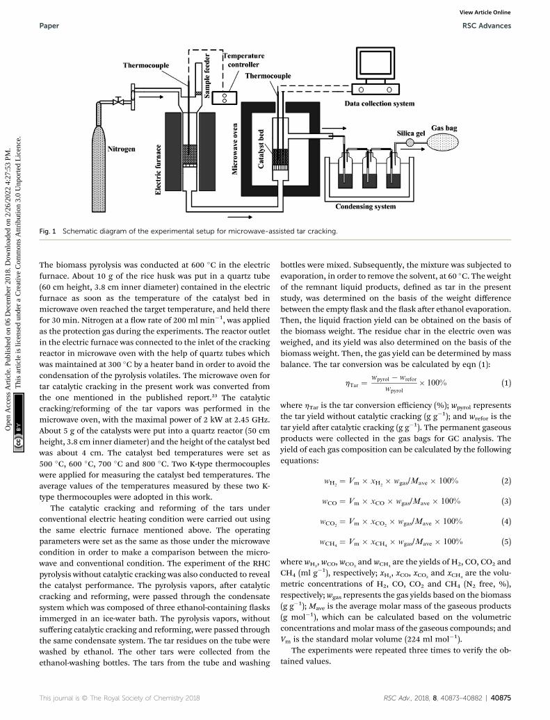
Fig. 1 Schematic diagram of the experimental setup for microwave-assisted tar cracking.
Paper RSC Advances
Ope
n A
cces
s A
rtic
le. P
ublis
hed
on 0
6 D
ecem
ber
2018
. Dow
nloa
ded
on 2
/26/
2022
4:2
7:53
PM
. T
his
artic
le is
lice
nsed
und
er a
Cre
ativ
e C
omm
ons
Attr
ibut
ion
3.0
Unp
orte
d L
icen
ce.
View Article Online
The biomass pyrolysis was conducted at 600 �C in the electricfurnace. About 10 g of the rice husk was put in a quartz tube(60 cm height, 3.8 cm inner diameter) contained in the electricfurnace as soon as the temperature of the catalyst bed inmicrowave oven reached the target temperature, and held therefor 30 min. Nitrogen at a ow rate of 200 ml min�1, was appliedas the protection gas during the experiments. The reactor outletin the electric furnace was connected to the inlet of the crackingreactor in microwave oven with the help of quartz tubes whichwas maintained at 300 �C by a heater band in order to avoid thecondensation of the pyrolysis volatiles. The microwave oven fortar catalytic cracking in the present work was converted fromthe one mentioned in the published report.23 The catalyticcracking/reforming of the tar vapors was performed in themicrowave oven, with the maximal power of 2 kW at 2.45 GHz.About 5 g of the catalysts were put into a quartz reactor (50 cmheight, 3.8 cm inner diameter) and the height of the catalyst bedwas about 4 cm. The catalyst bed temperatures were set as500 �C, 600 �C, 700 �C and 800 �C. Two K-type thermocoupleswere applied for measuring the catalyst bed temperatures. Theaverage values of the temperatures measured by these two K-type thermocouples were adopted in this work.
The catalytic cracking and reforming of the tars underconventional electric heating condition were carried out usingthe same electric furnace mentioned above. The operatingparameters were set as the same as those under the microwavecondition in order to make a comparison between the micro-wave and conventional condition. The experiment of the RHCpyrolysis without catalytic cracking was also conducted to revealthe catalyst performance. The pyrolysis vapors, aer catalyticcracking and reforming, were passed through the condensatesystem which was composed of three ethanol-containing asksimmerged in an ice-water bath. The pyrolysis vapors, withoutsuffering catalytic cracking and reforming, were passed throughthe same condensate system. The tar residues on the tube werewashed by ethanol. The other tars were collected from theethanol-washing bottles. The tars from the tube and washing
This journal is © The Royal Society of Chemistry 2018
bottles were mixed. Subsequently, the mixture was subjected toevaporation, in order to remove the solvent, at 60 �C. The weightof the remnant liquid products, dened as tar in the presentstudy, was determined on the basis of the weight differencebetween the empty ask and the ask aer ethanol evaporation.Then, the liquid fraction yield can be obtained on the basis ofthe biomass weight. The residue char in the electric oven wasweighed, and its yield was also determined on the basis of thebiomass weight. Then, the gas yield can be determined by massbalance. The tar conversion was be calculated by eqn (1):
hTar ¼wpyrol � wrefor
wpyrol
� 100% (1)
where hTar is the tar conversion efficiency (%); wpyrol representsthe tar yield without catalytic cracking (g g�1); and wrefor is thetar yield aer catalytic cracking (g g�1). The permanent gaseousproducts were collected in the gas bags for GC analysis. Theyield of each gas composition can be calculated by the followingequations:
wH2¼ Vm � xH2
� wgas/Mave � 100% (2)
wCO ¼ Vm � xCO � wgas/Mave � 100% (3)
wCO2¼ Vm � xCO2
� wgas/Mave � 100% (4)
wCH4¼ Vm � xCH4
� wgas/Mave � 100% (5)
where wH2, wCO, wCO2
and wCH4are the yields of H2, CO, CO2 and
CH4 (ml g�1), respectively; xH2, xCO, xCO2
and xCH4are the volu-
metric concentrations of H2, CO, CO2 and CH4 (N2 free, %),respectively; wgas represents the gas yields based on the biomass(g g�1); Mave is the average molar mass of the gaseous products(g mol�1), which can be calculated based on the volumetricconcentrations andmolar mass of the gaseous compounds; andVm is the standard molar volume (224 ml mol�1).
The experiments were repeated three times to verify the ob-tained values.
RSC Adv., 2018, 8, 40873–40882 | 40875
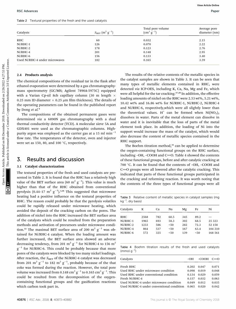
Table 2 Textural properties of the fresh and the used catalysts
Catalysts SBET (m2 g�1)Total pore volume(cm3 g�1)
Average porediameter (nm)
RHC 60 0.032 2.15Ni/RHC-1 126 0.070 2.22Ni/RHC-2 178 0.123 2.76Ni/RHC-4 201 0.148 2.95Ni/RHC-6 156 0.133 3.40Used Ni/RHC-4 under microwaves 182 0.165 3.59
RSC Advances Paper
Ope
n A
cces
s A
rtic
le. P
ublis
hed
on 0
6 D
ecem
ber
2018
. Dow
nloa
ded
on 2
/26/
2022
4:2
7:53
PM
. T
his
artic
le is
lice
nsed
und
er a
Cre
ativ
e C
omm
ons
Attr
ibut
ion
3.0
Unp
orte
d L
icen
ce.
View Article Online
2.4 Products analysis
The chemical compositions of the residual tar in the ask aerethanol evaporation were determined by a gas chromatography-mass spectrometry (GC/MS; Agilent 7890A-5975C) equippedwith a Varian Cp-sil 8cb capillary column (30 m length �0.25 mm ID diameter � 0.25 mm lm thickness). The details ofthe operating parameters can be found in the published reportby Dong et al.9
The compositions of the obtained permanent gases weredetermined via a 6890N gas chromatography with a dualthermal conductivity detector (TCD). A molecular sieve 5A andGDX401 were used as the chromatographic columns. High-purity argon was employed as the carrier gas at a 15 ml min�1
ow rate. The temperatures of the detector, oven and injectorwere set as 150, 80, and 100 �C, respectively.
Table 4 Boehm titration results of the fresh and used catalysts(mmol g�1)
Catalysts –OH –COOH C]O
Fresh RHC 0.202 0.047 0.071Used RHC under microwave condition 0.098 0.019 0.048Used RHC under conventional condition 0.134 0.029 0.059Fresh Ni/RHC-4 0.157 0.032 0.063Used Ni/RHC-4 under microwave condition 0.049 0.012 0.035Used Ni/RHC-4 under conventional condition 0.065 0.020 0.042
Table 3 Relative content of metallic species in catalyst samples (mgkg�1, dry basis)
Catalysts K Ca Na Mg Fe Ni
RHC 2568 782 60.5 345 89.2 —Ni/RHC-1 1965 693 58.3 302 68.5 25 323Ni/RHC-2 1233 586 <50 282 72.3 52 158Ni/RHC-4 864 537 <50 167 63.4 104 210Ni/RHC-6 572 325 <50 139 <50 168 561
3. Results and discussion3.1 Catalyst characterization
The textural properties of the fresh and used catalysts are pre-sented in Table 2. It is found that the RHC has a relatively highvalue of the BET surface area (60 m2 g�1). This value is muchhigher than that of the RHC obtained from conventionalpyrolysis (0.44–17 m2 g�1).3,26 This suggested that microwaveheating had a positive inuence on the textural properties ofRHC. The reason could probably be that the pyrolysis volatilescould be rapidly released under microwave heating, whichavoided the deposit of the cracking carbon on the pores. Theaddition of nickel into the RHC increased the BET surface areaof the catalysts which could be resulted from the preparationmethods and activation of precursors under microwave condi-tion.23 The maximal BET surface area of 200 m2 g�1 was ob-tained for Ni/RHC-4 catalyst. When the loading amount wasfurther increased, the BET surface area showed an adversedecreasing tendency, from 201 m2 g�1 for Ni/RHC-4 to 156 m2
g�1 for Ni/RHC-6. This could be probably because that morepores of the catalysts were blocked by too many nickel loadings.Aer reaction, the SBET of the Ni/RHC-4 catalyst was decreasedfrom 201 m2 g�1 to 182 m2 g�1, probably because of the thatcoke was formed during the reaction. However, the total porevolume was increased from 0.148 cm3 g�1 to 0.165 cm3 g�1. Thiscould be resulted from the decomposition of the oxygen-containing functional groups and the gasication reactionswhich carbon took part in.
40876 | RSC Adv., 2018, 8, 40873–40882
The results of the relative contents of the metallic species inthe catalyst samples are shown in Table 3. It can be seen thatmany types of metallic elements contained in RHC, weredetected via ICP-OES, including K, Ca, Na, Mg and Fe, whichwere all helpful for the tar cracking.27,28 In addition, the effectiveloading amounts of nickel on the RHC were 2.53 wt%, 5.21 wt%,10.42 wt% and 16.86 wt% for Ni/RHC-1, Ni/RHC-2, Ni/RHC-4and Ni/RHC-6, respectively,which were all slightly lower thanthe theoretical values. H+ can be formed when Ni(NO3)2dissolves in water. Parts of the metal element can dissolve inwater and it is inevitable that the loss of parts of the metalelement took place. In addition, the loading of Ni into thesupport would increase the mass of the catalyst, which wouldalso decrease the content of metallic species contained in theRHC support.
The Boehm titration method,25 can be applied to determinethe oxygen-containing functional groups on the RHC surface,including –OH, –COOH and C]O. Table 4 showed the contentsof these functional groups, before and aer catalytic cracking at700 �C. It can be found that the contents of –OH, –COOH andC]O groups were all lowered aer the catalytic cracking. Thisindicated that parts of these functional groups participated inthe cracking and reforming reaction. It was worth noting thatthe contents of the three types of functional groups were all
This journal is © The Royal Society of Chemistry 2018
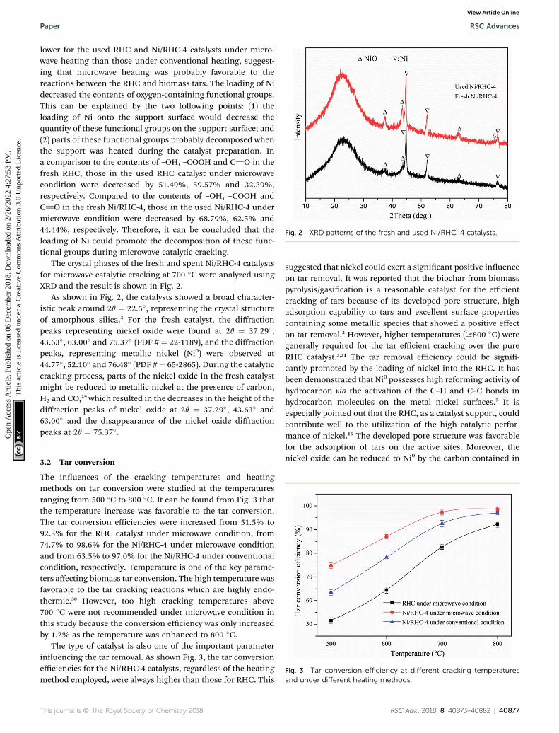
Fig. 2 XRD patterns of the fresh and used Ni/RHC-4 catalysts.
Paper RSC Advances
Ope
n A
cces
s A
rtic
le. P
ublis
hed
on 0
6 D
ecem
ber
2018
. Dow
nloa
ded
on 2
/26/
2022
4:2
7:53
PM
. T
his
artic
le is
lice
nsed
und
er a
Cre
ativ
e C
omm
ons
Attr
ibut
ion
3.0
Unp
orte
d L
icen
ce.
View Article Online
lower for the used RHC and Ni/RHC-4 catalysts under micro-wave heating than those under conventional heating, suggest-ing that microwave heating was probably favorable to thereactions between the RHC and biomass tars. The loading of Nidecreased the contents of oxygen-containing functional groups.This can be explained by the two following points: (1) theloading of Ni onto the support surface would decrease thequantity of these functional groups on the support surface; and(2) parts of these functional groups probably decomposed whenthe support was heated during the catalyst preparation. Ina comparison to the contents of –OH, –COOH and C]O in thefresh RHC, those in the used RHC catalyst under microwavecondition were decreased by 51.49%, 59.57% and 32.39%,respectively. Compared to the contents of –OH, –COOH andC]O in the fresh Ni/RHC-4, those in the used Ni/RHC-4 undermicrowave condition were decreased by 68.79%, 62.5% and44.44%, respectively. Therefore, it can be concluded that theloading of Ni could promote the decomposition of these func-tional groups during microwave catalytic cracking.
The crystal phases of the fresh and spent Ni/RHC-4 catalystsfor microwave catalytic cracking at 700 �C were analyzed usingXRD and the result is shown in Fig. 2.
As shown in Fig. 2, the catalysts showed a broad character-istic peak around 2q ¼ 22.5�, representing the crystal structureof amorphous silica.3 For the fresh catalyst, the diffractionpeaks representing nickel oxide were found at 2q ¼ 37.29�,43.63�, 63.00� and 75.37� (PDF # ¼ 22-1189), and the diffractionpeaks, representing metallic nickel (Ni0) were observed at44.77�, 52.10� and 76.48� (PDF #¼ 65-2865). During the catalyticcracking process, parts of the nickel oxide in the fresh catalystmight be reduced to metallic nickel at the presence of carbon,H2 and CO,29 which resulted in the decreases in the height of thediffraction peaks of nickel oxide at 2q ¼ 37.29�, 43.63� and63.00� and the disappearance of the nickel oxide diffractionpeaks at 2q ¼ 75.37�.
Fig. 3 Tar conversion efficiency at different cracking temperaturesand under different heating methods.
3.2 Tar conversion
The inuences of the cracking temperatures and heatingmethods on tar conversion were studied at the temperaturesranging from 500 �C to 800 �C. It can be found from Fig. 3 thatthe temperature increase was favorable to the tar conversion.The tar conversion efficiencies were increased from 51.5% to92.3% for the RHC catalyst under microwave condition, from74.7% to 98.6% for the Ni/RHC-4 under microwave conditionand from 63.5% to 97.0% for the Ni/RHC-4 under conventionalcondition, respectively. Temperature is one of the key parame-ters affecting biomass tar conversion. The high temperature wasfavorable to the tar cracking reactions which are highly endo-thermic.30 However, too high cracking temperatures above700 �C were not recommended under microwave condition inthis study because the conversion efficiency was only increasedby 1.2% as the temperature was enhanced to 800 �C.
The type of catalyst is also one of the important parameterinuencing the tar removal. As shown Fig. 3, the tar conversionefficiencies for the Ni/RHC-4 catalysts, regardless of the heatingmethod employed, were always higher than those for RHC. This
This journal is © The Royal Society of Chemistry 2018
suggested that nickel could exert a signicant positive inuenceon tar removal. It was reported that the biochar from biomasspyrolysis/gasication is a reasonable catalyst for the efficientcracking of tars because of its developed pore structure, highadsorption capability to tars and excellent surface propertiescontaining some metallic species that showed a positive effecton tar removal.3 However, higher temperatures ($800 �C) weregenerally required for the tar efficient cracking over the pureRHC catalyst.3,31 The tar removal efficiency could be signi-cantly promoted by the loading of nickel into the RHC. It hasbeen demonstrated that Ni0 possesses high reforming activity ofhydrocarbon via the activation of the C–H and C–C bonds inhydrocarbon molecules on the metal nickel surfaces.7 It isespecially pointed out that the RHC, as a catalyst support, couldcontribute well to the utilization of the high catalytic perfor-mance of nickel.16 The developed pore structure was favorablefor the adsorption of tars on the active sites. Moreover, thenickel oxide can be reduced to Ni0 by the carbon contained in
RSC Adv., 2018, 8, 40873–40882 | 40877

Fig. 4 Dependence of the tar conversion efficiency on the nickelloading at 700 �C under microwave condition.
RSC Advances Paper
Ope
n A
cces
s A
rtic
le. P
ublis
hed
on 0
6 D
ecem
ber
2018
. Dow
nloa
ded
on 2
/26/
2022
4:2
7:53
PM
. T
his
artic
le is
lice
nsed
und
er a
Cre
ativ
e C
omm
ons
Attr
ibut
ion
3.0
Unp
orte
d L
icen
ce.
View Article Online
RHC. Therefore, the Ni/RHC catalyst showed a higher catalyticactivity for tar conversion than the pure RHC.
The tar conversion efficiencies for the Ni/RHC-4 catalystssubjected to microwave heating were all higher than thoseunder conventional condition at the same temperatures.Compared to conventional heating, the tar conversion effi-ciencies were increased by 17.8%, 11.3%, 5.1% and 1.6% undermicrowave condition at 500 �C, 600 �C, 700 �C and 800 �C,respectively. However, the difference in the tar removal effi-ciency was decreased as the cracking temperature increased,suggesting that microwave heating could be more effective ontar removal than conventional heating at lower temperatures.Similar results can be found in published reports, in which thedifference between the microwave and conventional pyrolysis ofmicroalgae was also found to be decreased as the pyrolysistemperature increased, in terms of the product yields. Duringthe conventional heating process, the heat ows passedthrough the surfaces into the inside of the samples. In contrast,microwaves can directly generate heat within the catalyst due toits interaction with the samples, which is bound to result in thegeneration of the higher temperatures in the interior of thesamples. In addition, during microwave heating, a lot of smallhotspots have been discovered when carbon materials wereheated by microwaves.32 Whereas the overall temperaturecorresponds to those measured by the thermocouples, thetemperatures in these “hot spots” must be much higher.Therefore, the presence of the hotspots can promote theheterogeneous reactions between the solid catalyst and gases.32
In other words, it is the pseudo-catalytic effect of microwaveheating.33,34 It is worthwhile noting that the tar conversionefficiency reached up to 97.3% at 700 �C and was only slightlyincreased as the temperature increasing to 800 �C, for the Ni/RHC-4 catalyst under microwave condition. The tar conver-sion efficiency at 700 �C under microwave condition was evenhigher than that at 800 �C under conventional condition, alsoindicating that microwave heating was more effective onheterogeneous catalytic reactions.
The dependence of the tar conversion efficiency on the nickelloading amount at 700 �C is presented in Fig. 4. The tarconversion efficiencies were increased from 78.6% to 98.6%with the loading amount increasing from 0 wt% to 16.86 wt%,indicating that the loading amount had a signicant effect inthe tar cracking. This could be probably because that more Ni0
was produced during tar cracking when the content of nickelelement loaded into the support was higher.7 A rapid increase intar removal was found as the Ni loading amount increased from5.21 wt% to 10.42 wt%. However, the tar conversion efficiencyshowed a non-signicant increase as the loading amount wasfurther enhanced from 10.42 wt% to 16.86 wt%. A nickelloading amount that was too high decreased the surface area ofthe catalyst (Table 2). Therefore, the catalyst performance couldbe deteriorated by too much nickel loading.
3.3 Gaseous products
The non-condensable gaseous products consisted mainly of CO,CO2, H2 and CH4. The yield of each composition, depending on
40878 | RSC Adv., 2018, 8, 40873–40882
the cracking temperatures, is presented in Fig. 5. The yields ofCO and H2 were both enhanced as the temperature increasedfrom 500 �C to 800 �C in all operating situations, indicating thathigher cracking temperatures were favorable to the productionof syngas. The CO yields were increased from 105.4 ml g�1 to213.5 ml g�1 for the RHC catalyst under microwave condition,from 163.2 ml g�1 to 286.6 ml g�1 for the Ni/RHC-4 undermicrowave condition and from 127.3 ml g�1 to 261.3 ml g�1 forNi/RHC-4 under conventional condition. The H2 yields wereincreased from 84.3 ml g�1 to 192.9 ml g�1 for the RHC catalystunder microwave condition, 116.9 ml g�1 to 259.0 ml g�1 for Ni/RHC-4 under microwave condition and 98.9 ml g�1 to 217.8 mlg�1 for the Ni/RHC-4 under conventional condition. The volu-metric concentration of the syngas reached up to 74.82% whenthe Ni/RHC-4 catalyst was employed at 700 �C under microwavecondition. The tar cracking and reforming mechanisms couldbe generally expressed by several heterogeneous and homoge-neous reactions (reactions (6)–(13)).13
Tars / C + CnHm + gases (6)
CnHm + nCO2 / 2nCO + (m/2)H2 (7)
CnHm + nH2O / nCO + (n + m/2)H2 (8)
CnHm + 2H2O 4 nCO2 + (2n + m/2)H2 (9)
CH4 + H2O 4 CO + 3H2, DH298 K ¼ +206 kJ mol�1 (10)
CH4 + CO2 4 2CO + 2H2, DH298 K ¼ +247 kJ mol�1 (11)
C + H2O 4 CO + H2, DH298 K ¼ +131 kJ mol�1 (12)
C + 2H2O 4 CO + 2H2, DH298 K ¼ +173 kJ mol�1 (13)
On the basis of the Le Chatelier's principle, higher temper-atures could promote the endothermic reactions. Therefore, it
This journal is © The Royal Society of Chemistry 2018
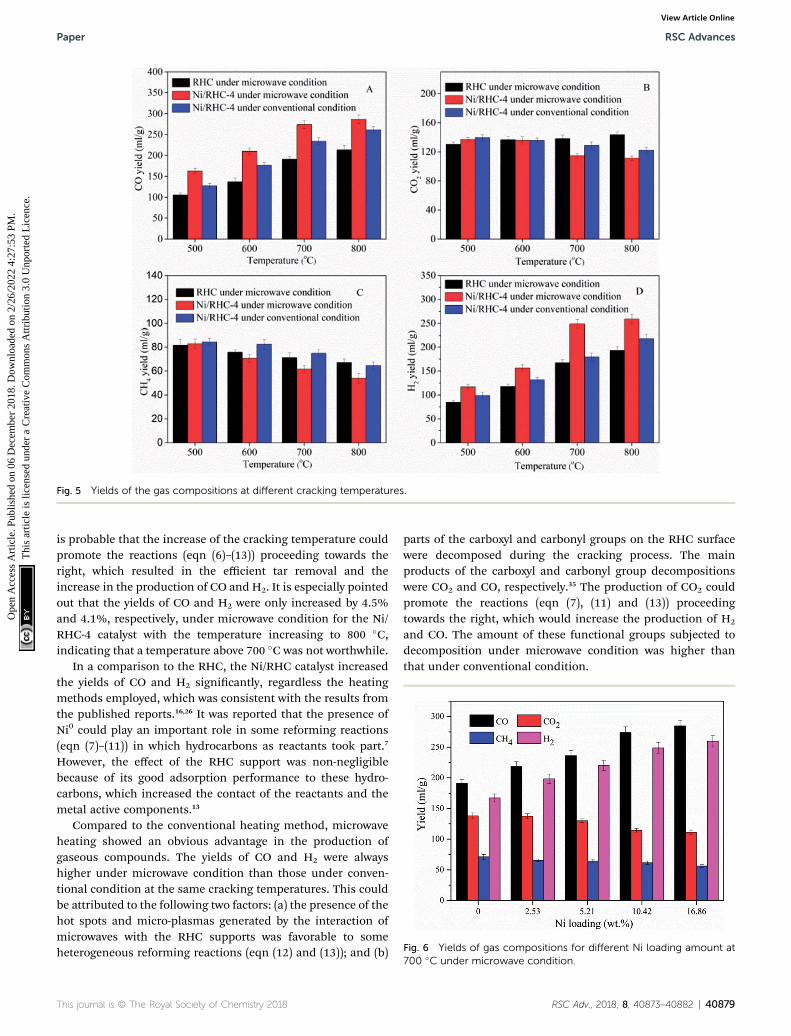
Fig. 6 Yields of gas compositions for different Ni loading amount at�
Fig. 5 Yields of the gas compositions at different cracking temperatures.
Paper RSC Advances
Ope
n A
cces
s A
rtic
le. P
ublis
hed
on 0
6 D
ecem
ber
2018
. Dow
nloa
ded
on 2
/26/
2022
4:2
7:53
PM
. T
his
artic
le is
lice
nsed
und
er a
Cre
ativ
e C
omm
ons
Attr
ibut
ion
3.0
Unp
orte
d L
icen
ce.
View Article Online
is probable that the increase of the cracking temperature couldpromote the reactions (eqn (6)–(13)) proceeding towards theright, which resulted in the efficient tar removal and theincrease in the production of CO and H2. It is especially pointedout that the yields of CO and H2 were only increased by 4.5%and 4.1%, respectively, under microwave condition for the Ni/RHC-4 catalyst with the temperature increasing to 800 �C,indicating that a temperature above 700 �C was not worthwhile.
In a comparison to the RHC, the Ni/RHC catalyst increasedthe yields of CO and H2 signicantly, regardless the heatingmethods employed, which was consistent with the results fromthe published reports.16,26 It was reported that the presence ofNi0 could play an important role in some reforming reactions(eqn (7)–(11)) in which hydrocarbons as reactants took part.7
However, the effect of the RHC support was non-negligiblebecause of its good adsorption performance to these hydro-carbons, which increased the contact of the reactants and themetal active components.13
Compared to the conventional heating method, microwaveheating showed an obvious advantage in the production ofgaseous compounds. The yields of CO and H2 were alwayshigher under microwave condition than those under conven-tional condition at the same cracking temperatures. This couldbe attributed to the following two factors: (a) the presence of thehot spots and micro-plasmas generated by the interaction ofmicrowaves with the RHC supports was favorable to someheterogeneous reforming reactions (eqn (12) and (13)); and (b)
This journal is © The Royal Society of Chemistry 2018
parts of the carboxyl and carbonyl groups on the RHC surfacewere decomposed during the cracking process. The mainproducts of the carboxyl and carbonyl group decompositionswere CO2 and CO, respectively.35 The production of CO2 couldpromote the reactions (eqn (7), (11) and (13)) proceedingtowards the right, which would increase the production of H2
and CO. The amount of these functional groups subjected todecomposition under microwave condition was higher thanthat under conventional condition.
700 C under microwave condition.
RSC Adv., 2018, 8, 40873–40882 | 40879
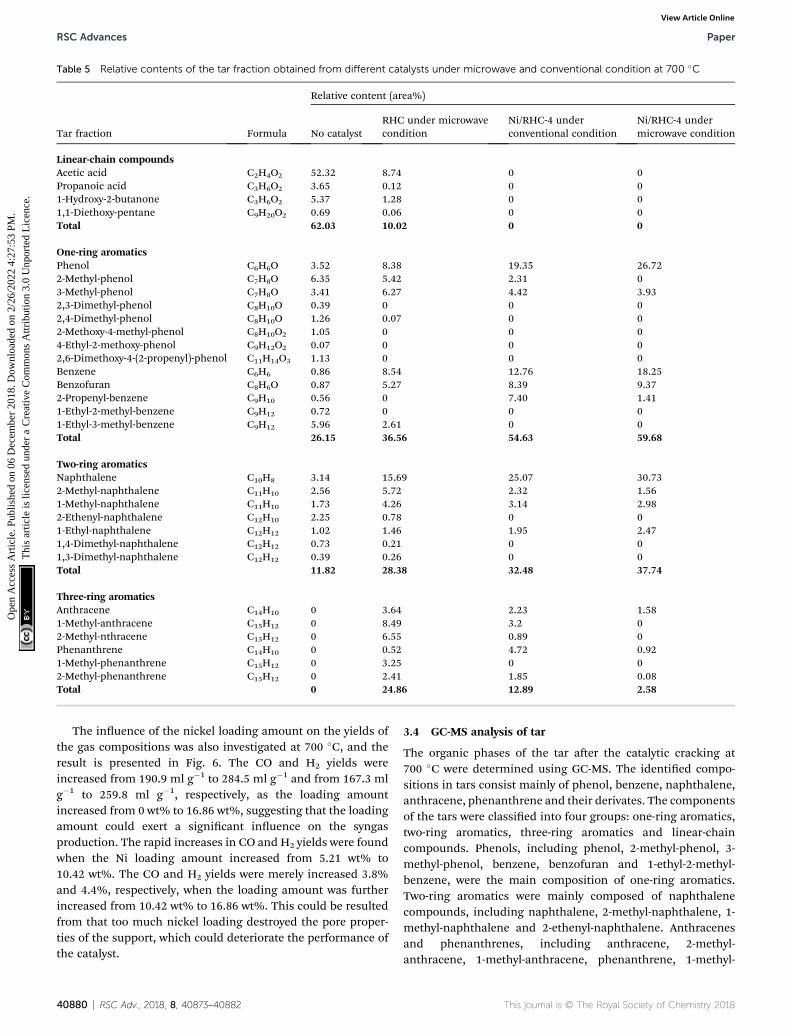
Table 5 Relative contents of the tar fraction obtained from different catalysts under microwave and conventional condition at 700 �C
Tar fraction Formula
Relative content (area%)
No catalystRHC under microwavecondition
Ni/RHC-4 underconventional condition
Ni/RHC-4 undermicrowave condition
Linear-chain compoundsAcetic acid C2H4O2 52.32 8.74 0 0Propanoic acid C3H6O2 3.65 0.12 0 01-Hydroxy-2-butanone C3H6O2 5.37 1.28 0 01,1-Diethoxy-pentane C9H20O2 0.69 0.06 0 0Total 62.03 10.02 0 0
One-ring aromaticsPhenol C6H6O 3.52 8.38 19.35 26.722-Methyl-phenol C7H8O 6.35 5.42 2.31 03-Methyl-phenol C7H8O 3.41 6.27 4.42 3.932,3-Dimethyl-phenol C8H10O 0.39 0 0 02,4-Dimethyl-phenol C8H10O 1.26 0.07 0 02-Methoxy-4-methyl-phenol C8H10O2 1.05 0 0 04-Ethyl-2-methoxy-phenol C9H12O2 0.07 0 0 02,6-Dimethoxy-4-(2-propenyl)-phenol C11H14O3 1.13 0 0 0Benzene C6H6 0.86 8.54 12.76 18.25Benzofuran C8H6O 0.87 5.27 8.39 9.372-Propenyl-benzene C9H10 0.56 0 7.40 1.411-Ethyl-2-methyl-benzene C9H12 0.72 0 0 01-Ethyl-3-methyl-benzene C9H12 5.96 2.61 0 0Total 26.15 36.56 54.63 59.68
Two-ring aromaticsNaphthalene C10H8 3.14 15.69 25.07 30.732-Methyl-naphthalene C11H10 2.56 5.72 2.32 1.561-Methyl-naphthalene C11H10 1.73 4.26 3.14 2.982-Ethenyl-naphthalene C12H10 2.25 0.78 0 01-Ethyl-naphthalene C12H12 1.02 1.46 1.95 2.471,4-Dimethyl-naphthalene C12H12 0.73 0.21 0 01,3-Dimethyl-naphthalene C12H12 0.39 0.26 0 0Total 11.82 28.38 32.48 37.74
Three-ring aromaticsAnthracene C14H10 0 3.64 2.23 1.581-Methyl-anthracene C15H12 0 8.49 3.2 02-Methyl-nthracene C15H12 0 6.55 0.89 0Phenanthrene C14H10 0 0.52 4.72 0.921-Methyl-phenanthrene C15H12 0 3.25 0 02-Methyl-phenanthrene C15H12 0 2.41 1.85 0.08Total 0 24.86 12.89 2.58
RSC Advances Paper
Ope
n A
cces
s A
rtic
le. P
ublis
hed
on 0
6 D
ecem
ber
2018
. Dow
nloa
ded
on 2
/26/
2022
4:2
7:53
PM
. T
his
artic
le is
lice
nsed
und
er a
Cre
ativ
e C
omm
ons
Attr
ibut
ion
3.0
Unp
orte
d L
icen
ce.
View Article Online
The inuence of the nickel loading amount on the yields ofthe gas compositions was also investigated at 700 �C, and theresult is presented in Fig. 6. The CO and H2 yields wereincreased from 190.9 ml g�1 to 284.5 ml g�1 and from 167.3 mlg�1 to 259.8 ml g�1, respectively, as the loading amountincreased from 0 wt% to 16.86 wt%, suggesting that the loadingamount could exert a signicant inuence on the syngasproduction. The rapid increases in CO and H2 yields were foundwhen the Ni loading amount increased from 5.21 wt% to10.42 wt%. The CO and H2 yields were merely increased 3.8%and 4.4%, respectively, when the loading amount was furtherincreased from 10.42 wt% to 16.86 wt%. This could be resultedfrom that too much nickel loading destroyed the pore proper-ties of the support, which could deteriorate the performance ofthe catalyst.
40880 | RSC Adv., 2018, 8, 40873–40882
3.4 GC-MS analysis of tar
The organic phases of the tar aer the catalytic cracking at700 �C were determined using GC-MS. The identied compo-sitions in tars consist mainly of phenol, benzene, naphthalene,anthracene, phenanthrene and their derivates. The componentsof the tars were classied into four groups: one-ring aromatics,two-ring aromatics, three-ring aromatics and linear-chaincompounds. Phenols, including phenol, 2-methyl-phenol, 3-methyl-phenol, benzene, benzofuran and 1-ethyl-2-methyl-benzene, were the main composition of one-ring aromatics.Two-ring aromatics were mainly composed of naphthalenecompounds, including naphthalene, 2-methyl-naphthalene, 1-methyl-naphthalene and 2-ethenyl-naphthalene. Anthracenesand phenanthrenes, including anthracene, 2-methyl-anthracene, 1-methyl-anthracene, phenanthrene, 1-methyl-
This journal is © The Royal Society of Chemistry 2018
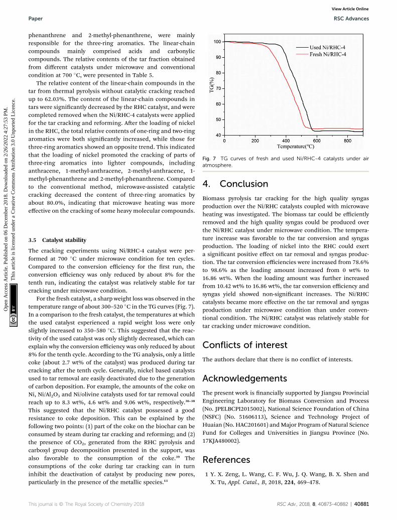
Fig. 7 TG curves of fresh and used Ni/RHC-4 catalysts under airatmosphere.
Paper RSC Advances
Ope
n A
cces
s A
rtic
le. P
ublis
hed
on 0
6 D
ecem
ber
2018
. Dow
nloa
ded
on 2
/26/
2022
4:2
7:53
PM
. T
his
artic
le is
lice
nsed
und
er a
Cre
ativ
e C
omm
ons
Attr
ibut
ion
3.0
Unp
orte
d L
icen
ce.
View Article Online
phenanthrene and 2-methyl-phenanthrene, were mainlyresponsible for the three-ring aromatics. The linear-chaincompounds mainly comprised acids and carbonyliccompounds. The relative contents of the tar fraction obtainedfrom different catalysts under microwave and conventionalcondition at 700 �C, were presented in Table 5.
The relative content of the linear-chain compounds in thetar from thermal pyrolysis without catalytic cracking reachedup to 62.03%. The content of the linear-chain compounds intars were signicantly decreased by the RHC catalyst, and werecompleted removed when the Ni/RHC-4 catalysts were appliedfor the tar cracking and reforming. Aer the loading of nickelin the RHC, the total relative contents of one-ring and two-ringaromatics were both signicantly increased, while those forthree-ring aromatics showed an opposite trend. This indicatedthat the loading of nickel promoted the cracking of parts ofthree-ring aromatics into lighter compounds, includinganthracene, 1-methyl-anthracene, 2-methyl-anthracene, 1-methyl-phenanthrene and 2-methyl-phenanthrene. Comparedto the conventional method, microwave-assisted catalyticcracking decreased the content of three-ring aromatics byabout 80.0%, indicating that microwave heating was moreeffective on the cracking of some heavy molecular compounds.
3.5 Catalyst stability
The cracking experiments using Ni/RHC-4 catalyst were per-formed at 700 �C under microwave condition for ten cycles.Compared to the conversion efficiency for the rst run, theconversion efficiency was only reduced by about 8% for thetenth run, indicating the catalyst was relatively stable for tarcracking under microwave condition.
For the fresh catalyst, a sharp weight loss was observed in thetemperature range of about 300–520 �C in the TG curves (Fig. 7).In a comparison to the fresh catalyst, the temperatures at whichthe used catalyst experienced a rapid weight loss were onlyslightly increased to 350–580 �C. This suggested that the reac-tivity of the used catalyst was only slightly decreased, which canexplain why the conversion efficiency was only reduced by about8% for the tenth cycle. According to the TG analysis, only a littlecoke (about 2.7 wt% of the catalyst) was produced during tarcracking aer the tenth cycle. Generally, nickel based catalystsused to tar removal are easily deactivated due to the generationof carbon deposition. For example, the amounts of the coke onNi, Ni/Al2O3 and Ni/olivine catalysts used for tar removal couldreach up to 8.3 wt%, 4.6 wt% and 9.06 wt%, respectively.36–38
This suggested that the Ni/RHC catalyst possessed a goodresistance to coke deposition. This can be explained by thefollowing two points: (1) part of the coke on the biochar can beconsumed by steam during tar cracking and reforming; and (2)the presence of CO2, generated from the RHC pyrolysis andcarboxyl group decomposition presented in the support, wasalso favorable to the consumption of the coke.39 Theconsumptions of the coke during tar cracking can in turninhibit the deactivation of catalyst by producing new pores,particularly in the presence of the metallic species.13
This journal is © The Royal Society of Chemistry 2018
4. Conclusion
Biomass pyrolysis tar cracking for the high quality syngasproduction over the Ni/RHC catalysts coupled with microwaveheating was investigated. The biomass tar could be efficientlyremoved and the high quality syngas could be produced overthe Ni/RHC catalyst under microwave condition. The tempera-ture increase was favorable to the tar conversion and syngasproduction. The loading of nickel into the RHC could exerta signicant positive effect on tar removal and syngas produc-tion. The tar conversion efficiencies were increased from 78.6%to 98.6% as the loading amount increased from 0 wt% to16.86 wt%. When the loading amount was further increasedfrom 10.42 wt% to 16.86 wt%, the tar conversion efficiency andsyngas yield showed non-signicant increases. The Ni/RHCcatalysts became more effective on the tar removal and syngasproduction under microwave condition than under conven-tional condition. The Ni/RHC catalyst was relatively stable fortar cracking under microwave condition.
Conflicts of interest
The authors declare that there is no conict of interests.
Acknowledgements
The present work is nancially supported by Jiangsu ProvincialEngineering Laboratory for Biomass Conversion and Process(No. JPELBCPI2015002), National Science Foundation of China(NSFC) (No. 51606113), Science and Technology Project ofHuaian (No. HAC201601) andMajor Program of Natural ScienceFund for Colleges and Universities in Jiangsu Province (No.17KJA480002).
References
1 Y. X. Zeng, L. Wang, C. F. Wu, J. Q. Wang, B. X. Shen andX. Tu, Appl. Catal., B, 2018, 224, 469–478.
RSC Adv., 2018, 8, 40873–40882 | 40881
RSC Advances Paper
Ope
n A
cces
s A
rtic
le. P
ublis
hed
on 0
6 D
ecem
ber
2018
. Dow
nloa
ded
on 2
/26/
2022
4:2
7:53
PM
. T
his
artic
le is
lice
nsed
und
er a
Cre
ativ
e C
omm
ons
Attr
ibut
ion
3.0
Unp
orte
d L
icen
ce.
View Article Online
2 M. Shahbaz, S. Yusup, A. Inayat, D. O. Patrick, A. Pratamaand M. Ammar, Bioresour. Technol., 2017, 241, 284–295.
3 F. Guo, X. Li, Y. Liu, K. Peng and C. G. Z. Rao, Energy Convers.Manage., 2018, 167, 81–90.
4 A. Paethanom, S. Nakahara, M. Kobayashi, P. Prawisudhaand K. Yoshikawa, Fuel Process. Technol., 2012, 104, 144–154.
5 L. Fagbemi, L. Khezami and R. Capart, Appl. Energy, 2001, 69,293–306.
6 Z. Min, S. Zhang, P. Yimsiri, Y. Wang, M. Asadullah and C. Li,Fuel, 2013, 106, 858–863.
7 Y. Shen, P. Zhao, Q. Shao, F. Takahashi and K. Yoshikawa,Appl. Energy, 2015, 160, 808–819.
8 G. Guan and X. H. A. Abudula, J. Adv. Catal. Sci. Techno.,2014, 1, 20–28.
9 Q. Dong, H. Li, M. Niu, C. Luo, J. Zhang, B. Qi, X. Li andW. Zhong, Bioresour. Technol., 2018, 266, 284–290.
10 P. Lu, Q. Huang, A. C. Bourtsalas, Y. Chi and J. Yan, WasteBiomass Valorization, 2017, DOI: 10.1007/s12649-017-0044-5.
11 T. Nordgreen, T. Liliedahl and K. Sjostrom, Fuel, 2006, 85,689–694.
12 Q. Dong, M. Niu, D. Bi, W. Liu, X. Gu and C. Lu, Bioresour.Technol., 2018, 256, 145–151.
13 Y. Shen, Renewable Sustainable Energy Rev., 2015, 43, 281–295.
14 K. Qian and A. Kumar, Fuel, 2017, 187, 128–136.15 Z. Zhao, N. Lakshminarayanan, S. L. Swartz, G. B. Arkenberg,
L. G. Felix, R. B. Slimane, C. C. Choi and U. S. Ozkan, Appl.Catal., A, 2015, 489, 42–50.
16 D. Wang, W. Yuan and W. Ji, Appl. Energy, 2011, 88, 1656–1663.
17 Q. Dong and Y. Xiong, Bioresour. Technol., 2014, 171, 127–131.
18 A. De la Hoz, A. Diaz-Ortiz and A. Moreno, Chem. Soc. Rev.,2005, 34, 164–178.
19 K. Shi, J. Yan, X. Luo, E. Lester and T. Wu, Energy Procedia,2017, 142, 1640–1646.
20 A. Warsita, K. A. Al-attab and Z. A. Zainal, Appl. Therm. Eng.,2017, 113, 722–730.
40882 | RSC Adv., 2018, 8, 40873–40882
21 L. Li, Z. Song, X. Zhao, C. Ma, X. Kong and F. Wang, Chem.Eng. J., 2016, 284, 1308–1316.
22 Q. Xie, F. C. Borges, Y. Cheng, Y. Wan, Y. Li, X. Lin, Y. Liu,F. Hussain, P. Chen and R. Ruan, Bioresour. Technol., 2014,156, 291–296.
23 S. Zhang, Q. Dong, L. Zhang and Y. Xiong, Bioresour.Technol., 2015, 191, 17–23.
24 S. Zhang, Q. Dong, L. Zhang, Y. Xiong, X. Liu and S. Zhu,Bioresour. Technol., 2015, 193, 442–448.
25 H. P. Boehm, Carbon, 1994, 32, 759–769.26 Y. Shen, P. Zhao, Q. Shao, D. Ma, F. Takahashi and
K. Yoshikawa, Appl. Catal., B, 2014, 152, 140–151.27 D. Feng, Y. Zhao, Y. Zhang, Z. Zhang and S. Sun, Int. J.
Hydrogen Energy, 2017, 42, 21686–21696.28 Q. Dong, X. Li, Z. Wang, Y. Bi, R. Yang, J. Zhang, H. Luo,
M. Niu, B. Qi and C. Lu, Bioresour. Technol., 2017, 243,755–759.
29 Y. Shen and K. Yoshikawa, Ind. Eng. Chem. Res., 2014, 53,10929–10942.
30 C. C. Xu, J. Donald, E. Byambajav and Y. Ohtsuka, Fuel, 2010,89, 1784–1795.
31 M. Hu, M. Laghari, B. Cui, B. Xiao, B. Zhang and D. Guo,Energy, 2018, 145, 228–273.
32 A. Dominguez, B. Fidalgo, Y. Fernandez, J. J. Pis andJ. A. Menendez, Int. J. Hydrogen Energy, 2007, 32, 4792–4799.
33 Y. Hou, S. Qi, H. You, Z. Huang and Q. Niu, J. Environ.Manage., 2018, 228, 312–318.
34 P. Lestinsky, B. Grycova, A. Martaus and L. Matejova, J. Anal.Appl. Pyrolysis, 2017, 124, 175–179.
35 H. Yang, R. Yan, H. Chen, D. H. Lee and C. Zheng, Fuel, 2007,86, 1781–1788.
36 M. Artetxe, M. A. Nahil, M. Olazar and P. T. Williams, Fuel,2016, 184, 629–636.
37 H. J. Park, S. H. Park, J. M. Sohn, J. Park, J. Jeon, S. ` Kim andY. Park, Bioresour. Technol., 2010, 101, S101–S103.
38 X. Yang, S. Xu, H. Xu, X. Liu and C. Liu, Catal. Commun.,2010, 11, 383–386.
39 J. L. Figueiredo, M. F. R. Pereira, M. M. A. Freitas andJ. J. M. Orfao, Carbon, 1999, 37, 1379–1389.
This journal is © The Royal Society of Chemistry 2018