Embed Size (px)
Citation preview
4
Biomechanical Characteristics of the Bone
Antonia Dalla Pria Bankoff University Of Campinas
Brazil
1. Introduction
The bone tissue is strong and one of the most rigid structures of the body due to its combination of inorganic and organic elements. The minerals calcium and phosphate, together with collagen, constitute the organic element of the bone being responsible for approximately 60 to 70% of the bone tissue. Water constitutes approximately 25 to 30% of the bone tissue weight. (Alberts et al., 1994; Junqueira & Carneiro, 1997, 1999). The bone tissue is a viscous-elastic material whose mechanical properties are affected by its deformation grade. The flexibility properties of the bone are provided by the collagen material of the bone. The collagen content gives the bone the ability to support tense loads. The bone is also a fragile material and its force depends on the load mechanism. The fragility grade of the bone depends on the mineral constituents that give it the ability to support compressive loads. (Alberts. et al., 1994; Junqueira & Carneiro, 1997, 1999). Re-absorption and Bone Deposit - Bone is a highly adaptive material and very sensitive to disuse, immobilization or vigorous activity and high load levels. The bone tissue can be separated and may change its properties and setting in response to the mechanical demand. It was determined at first by the German anatomist, Julius Wolff, that gave us the theory on the bone development named Wolff Law, that says: "Each change in the form and function of a bone or only its function is followed by certain definitive changes in its internal architecture, and secondary changes equally definitive in its external compliance, in accordance to the mathematics law". (Alberts et al., 1994; Junqueira & Carneiro, 1997, 1999).
2. Bone strength and hardness
The behavior of any material under different load conditions is determined by its strength and hardness. When an external force is applied in a bone or in any other material, there is an internal reaction. The strength may be assessed by checking the relation between the load imposed (external force) and the quantity of deformation (internal reaction) that takes place in the material, known as load-deformation curve. (Holtrop, 1975). Anisotropic Characteristics Bone tissue -Is an anisotropic material, indicating that the bone behavior will change depending on the direction of the load application. In general, the bone tissue may lead to higher loads in the longitudinal direction and a lesser quantity of load when applied over the bone surface. The bone is strong to support loads in the longitudinal direction because it is used to receive loads in this direction. (Holtrop, 1975). Viscoelastic Characteristics - The bone is also viscoelastic, which means that it responds differently depending on the speed to which the load is applied and the length of the load.
www.intechopen.com
Human Musculoskeletal Biomechanics
62
Fig. 1.1. This mean section of the proximal tip of the femur shows both the compact bone and the sponge bone. The dense compact bone covers the external part of the bone, going downside in order to form the bone body. The sponge bone is found in the tips and is identified by its truss appearance. Watch for the curvature in the trabeculae, which is formed to support the stresses. Bankoff (2007, p. 122).
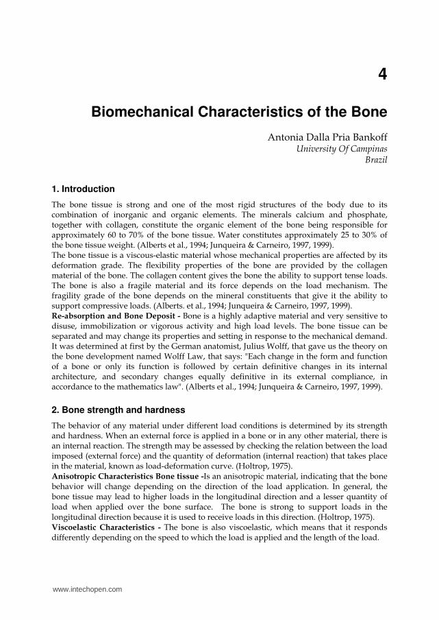
Fig. 1.2. The bone is considered anisotropic because it responds differently when the forces are applied in different directions. (A) The bone can lead to great forces applied in the longitudinal direction. (B) The bone is strong when it leads with forces applied transversally crossing its surface. Bankoff (2007, p. 123).
Trabeculae spongy bone
Compact bone
A
B
A
B
Spongy bone
www.intechopen.com
Biomechanical Characteristics of the Bone
63
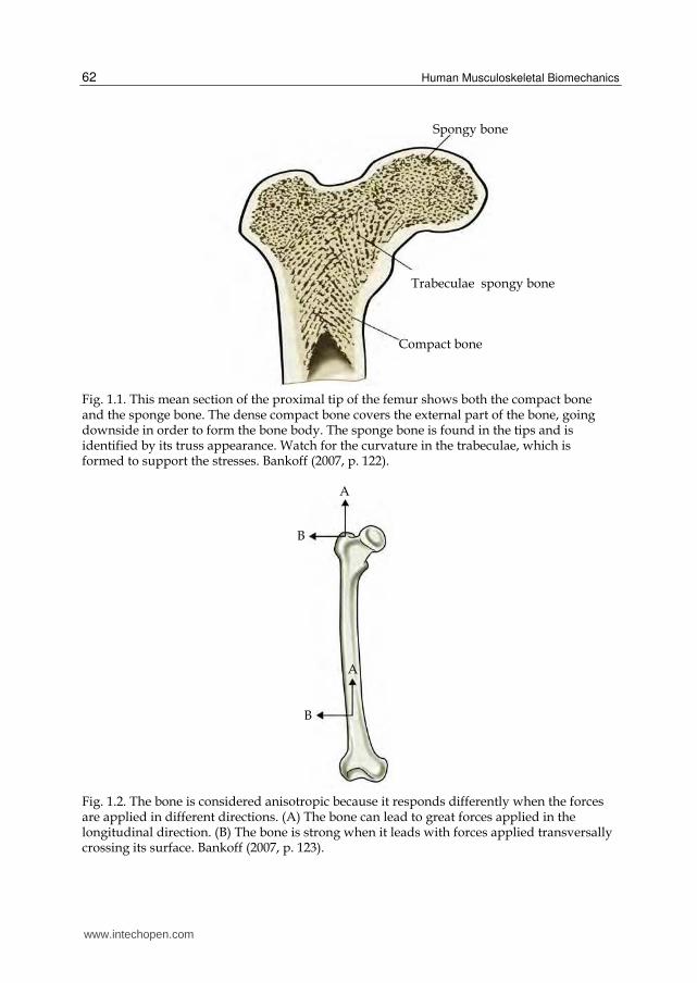
In very fast speeds of load placement, the bone can lead to higher loads before it fails or breaks. As showed in FIGURE 1.3, the bone that receives the load slowly breaks with a load that is approximately half of that it could support if the load was more quickly applied. Elastic Response - When the load is firstly applied, a bone is deformed by a change in the extent or angular format. The bone is deformed up to 3%. This is considered the elastic amplitude of the load-deformation curve because, when the load is removed, the bone is recovered and goes back to the original format or extent. The stress-distension or load-deformation curve is presented in FIGURE 1.4. An exam of this curve may be used in order to determine if a material is hard, flexible, fragile, strong or weak. The curve showed could represent a material that is strong and flexible. (Hay, 1982; Holtrop, 1975). Plastic Response - With the continuous placement of load on the bone tissue, its deformation point is reached, after which the external fibers of the bone tissue will start to cede, experiencing micro-breaks and disconnection of the material within the bone. (Hay, 1982; Holtrop, 1975).
Fig. 1.3. The bone is considered viscoelastic because it responds differently when it receives loads in different speeds. (A) When it receives the load quickly, the bone responds more rigidly, and may handle a higher load before it breaks. (B) When it receives the load slowly, the bone is not so rigid or strong, breaking under lesser loads. Bankoff (2007, p.123 ).
To which we name plastic or non-elastic phase in the load-deformation curve. The bone tissue starts to deform permanently and eventually breaks if the load continues in the non-elastic phase. Thus, when the load is removed, the bone tissue does not retake the original extent and is permanently elongated. (Hay, 1982; Holtrop, 1975; Bankoff, 2007). Strength - The strength of the bone or any other material is defined by the point of failure or by the load sustained before the failure. The strength may also be analyzed in terms of storage of energy, the area under the load-deformation or stress-distension curve. (Hay, 1982; Holtrop, 1975; Bankoff, 2007).
Lo
ad A
B
Deformation
Fracture
Fracture
www.intechopen.com
Human Musculoskeletal Biomechanics
64
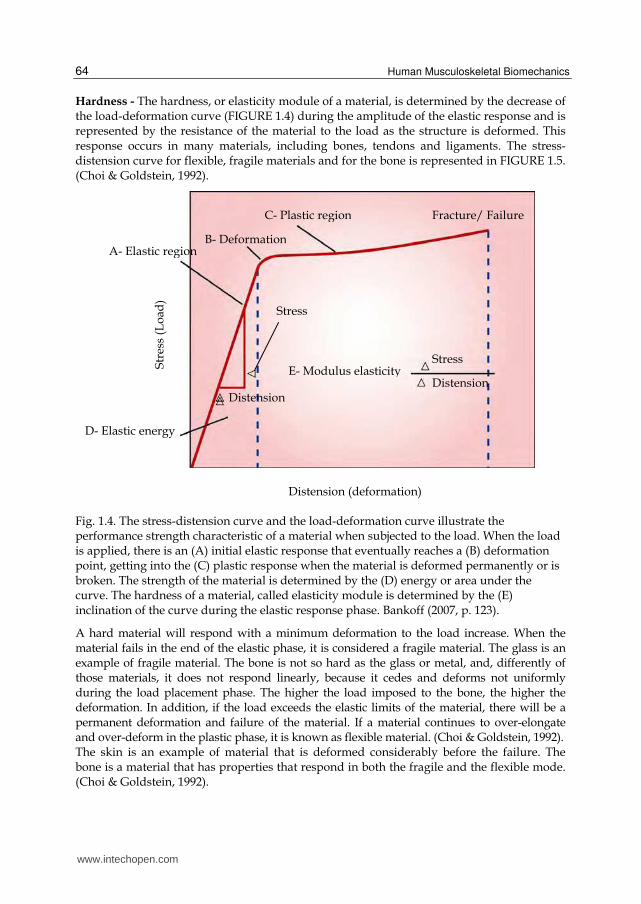
Hardness - The hardness, or elasticity module of a material, is determined by the decrease of the load-deformation curve (FIGURE 1.4) during the amplitude of the elastic response and is represented by the resistance of the material to the load as the structure is deformed. This response occurs in many materials, including bones, tendons and ligaments. The stress-distension curve for flexible, fragile materials and for the bone is represented in FIGURE 1.5. (Choi & Goldstein, 1992).
Fig. 1.4. The stress-distension curve and the load-deformation curve illustrate the performance strength characteristic of a material when subjected to the load. When the load is applied, there is an (A) initial elastic response that eventually reaches a (B) deformation point, getting into the (C) plastic response when the material is deformed permanently or is broken. The strength of the material is determined by the (D) energy or area under the curve. The hardness of a material, called elasticity module is determined by the (E) inclination of the curve during the elastic response phase. Bankoff (2007, p. 123).
A hard material will respond with a minimum deformation to the load increase. When the material fails in the end of the elastic phase, it is considered a fragile material. The glass is an example of fragile material. The bone is not so hard as the glass or metal, and, differently of those materials, it does not respond linearly, because it cedes and deforms not uniformly during the load placement phase. The higher the load imposed to the bone, the higher the deformation. In addition, if the load exceeds the elastic limits of the material, there will be a permanent deformation and failure of the material. If a material continues to over-elongate and over-deform in the plastic phase, it is known as flexible material. (Choi & Goldstein, 1992). The skin is an example of material that is deformed considerably before the failure. The bone is a material that has properties that respond in both the fragile and the flexible mode. (Choi & Goldstein, 1992).
A- Elastic region
D- Elastic energy
Str
ess
(Lo
ad)
B- Deformation
Fracture/ Failure C- Plastic region
E- Modulus elasticityStress
Distension
Distension (deformation)
Stress
Distension
www.intechopen.com
Biomechanical Characteristics of the Bone
65
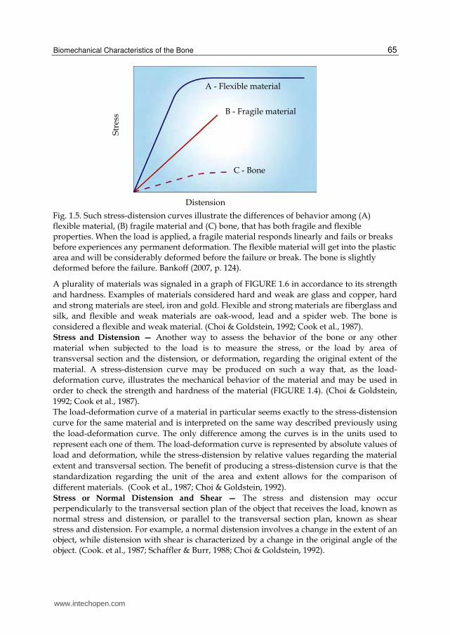
Fig. 1.5. Such stress-distension curves illustrate the differences of behavior among (A) flexible material, (B) fragile material and (C) bone, that has both fragile and flexible properties. When the load is applied, a fragile material responds linearly and fails or breaks before experiences any permanent deformation. The flexible material will get into the plastic area and will be considerably deformed before the failure or break. The bone is slightly deformed before the failure. Bankoff (2007, p. 124).
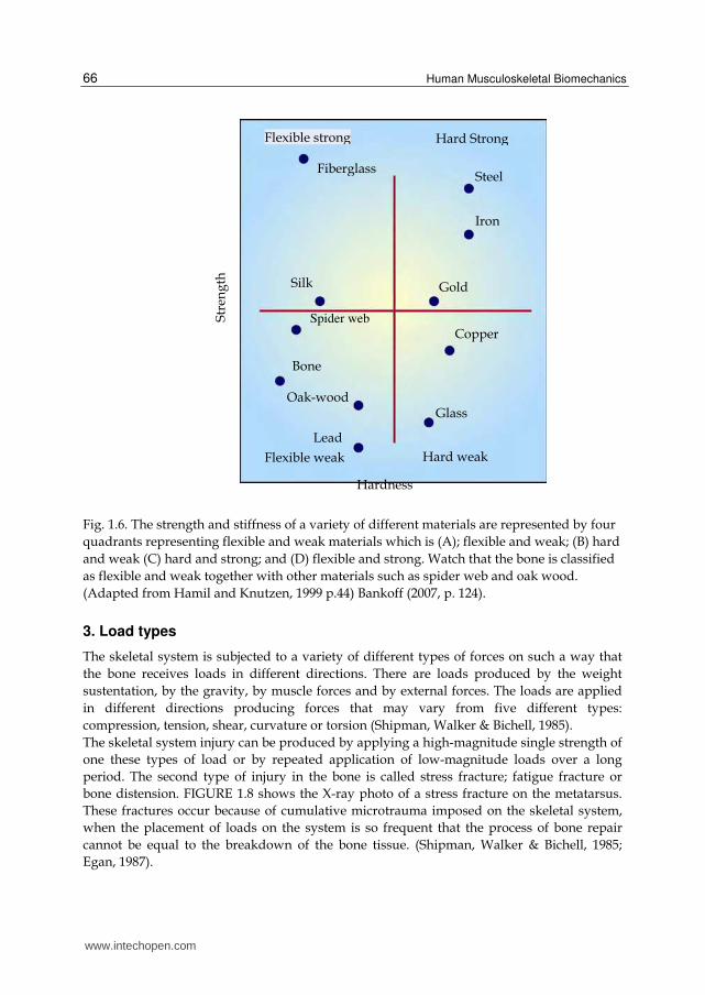
A plurality of materials was signaled in a graph of FIGURE 1.6 in accordance to its strength
and hardness. Examples of materials considered hard and weak are glass and copper, hard
and strong materials are steel, iron and gold. Flexible and strong materials are fiberglass and
silk, and flexible and weak materials are oak-wood, lead and a spider web. The bone is
considered a flexible and weak material. (Choi & Goldstein, 1992; Cook et al., 1987).
Stress and Distension — Another way to assess the behavior of the bone or any other
material when subjected to the load is to measure the stress, or the load by area of
transversal section and the distension, or deformation, regarding the original extent of the
material. A stress-distension curve may be produced on such a way that, as the load-
deformation curve, illustrates the mechanical behavior of the material and may be used in
order to check the strength and hardness of the material (FIGURE 1.4). (Choi & Goldstein,
1992; Cook et al., 1987).
The load-deformation curve of a material in particular seems exactly to the stress-distension
curve for the same material and is interpreted on the same way described previously using
the load-deformation curve. The only difference among the curves is in the units used to
represent each one of them. The load-deformation curve is represented by absolute values of
load and deformation, while the stress-distension by relative values regarding the material
extent and transversal section. The benefit of producing a stress-distension curve is that the
standardization regarding the unit of the area and extent allows for the comparison of
different materials. (Cook et al., 1987; Choi & Goldstein, 1992).
Stress or Normal Distension and Shear — The stress and distension may occur perpendicularly to the transversal section plan of the object that receives the load, known as normal stress and distension, or parallel to the transversal section plan, known as shear stress and distension. For example, a normal distension involves a change in the extent of an object, while distension with shear is characterized by a change in the original angle of the object. (Cook. et al., 1987; Schaffler & Burr, 1988; Choi & Goldstein, 1992).
A - Flexible material
B - Fragile material
C - Bone
Str
ess
Distension
www.intechopen.com
Human Musculoskeletal Biomechanics
66
Fig. 1.6. The strength and stiffness of a variety of different materials are represented by four
quadrants representing flexible and weak materials which is (A); flexible and weak; (B) hard
and weak (C) hard and strong; and (D) flexible and strong. Watch that the bone is classified
as flexible and weak together with other materials such as spider web and oak wood.
(Adapted from Hamil and Knutzen, 1999 p.44) Bankoff (2007, p. 124).
3. Load types
The skeletal system is subjected to a variety of different types of forces on such a way that
the bone receives loads in different directions. There are loads produced by the weight
sustentation, by the gravity, by muscle forces and by external forces. The loads are applied
in different directions producing forces that may vary from five different types:
compression, tension, shear, curvature or torsion (Shipman, Walker & Bichell, 1985).
The skeletal system injury can be produced by applying a high-magnitude single strength of
one these types of load or by repeated application of low-magnitude loads over a long
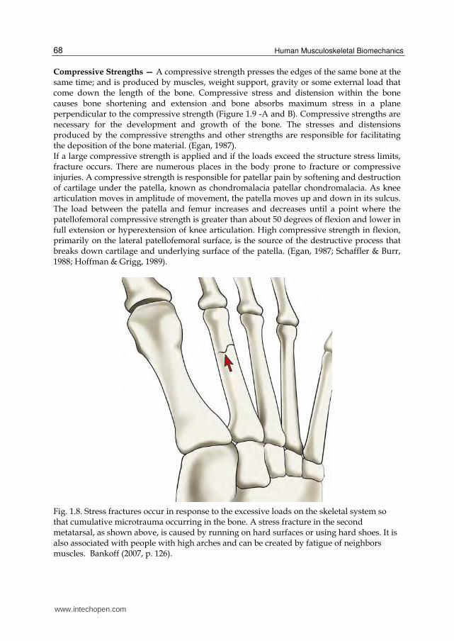
period. The second type of injury in the bone is called stress fracture; fatigue fracture or
bone distension. FIGURE 1.8 shows the X-ray photo of a stress fracture on the metatarsus.
These fractures occur because of cumulative microtrauma imposed on the skeletal system,
when the placement of loads on the system is so frequent that the process of bone repair
cannot be equal to the breakdown of the bone tissue. (Shipman, Walker & Bichell, 1985;
Egan, 1987).
Str
eng
th
Hardness
Fiberglass
Flexible strong Hard Strong
Steel
Iron
Gold
Copper
Glass
Bone
Oak-wood
Lead
Silk
Spider web
Flexible weak Hard weak
www.intechopen.com
Biomechanical Characteristics of the Bone
67
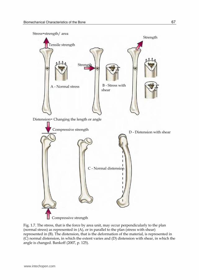
Fig. 1.7. The stress, that is the force by area unit, may occur perpendicularly to the plan (normal stress) as represented in (A), or in parallel to the plan (stress with shear) represented in (B). The distension, that is the deformation of the material, is represented in (C) normal distension, in which the extent varies and (D) distension with shear, in which the angle is changed. Bankoff (2007, p. 125).
Stress=strength/ area
Tensile strength
Strength
A - Normal stress B - Stress with shear
Strength
Compressive strength
Compressive strength
C - Normal distension
D - Distension with shear
Distension= Changing the length or angle
www.intechopen.com
Human Musculoskeletal Biomechanics
68
Compressive Strengths — A compressive strength presses the edges of the same bone at the same time; and is produced by muscles, weight support, gravity or some external load that come down the length of the bone. Compressive stress and distension within the bone causes bone shortening and extension and bone absorbs maximum stress in a plane perpendicular to the compressive strength (Figure 1.9 -A and B). Compressive strengths are necessary for the development and growth of the bone. The stresses and distensions produced by the compressive strengths and other strengths are responsible for facilitating the deposition of the bone material. (Egan, 1987). If a large compressive strength is applied and if the loads exceed the structure stress limits, fracture occurs. There are numerous places in the body prone to fracture or compressive injuries. A compressive strength is responsible for patellar pain by softening and destruction of cartilage under the patella, known as chondromalacia patellar chondromalacia. As knee articulation moves in amplitude of movement, the patella moves up and down in its sulcus. The load between the patella and femur increases and decreases until a point where the patellofemoral compressive strength is greater than about 50 degrees of flexion and lower in full extension or hyperextension of knee articulation. High compressive strength in flexion, primarily on the lateral patellofemoral surface, is the source of the destructive process that breaks down cartilage and underlying surface of the patella. (Egan, 1987; Schaffler & Burr, 1988; Hoffman & Grigg, 1989).
Fig. 1.8. Stress fractures occur in response to the excessive loads on the skeletal system so that cumulative microtrauma occurring in the bone. A stress fracture in the second metatarsal, as shown above, is caused by running on hard surfaces or using hard shoes. It is also associated with people with high arches and can be created by fatigue of neighbors muscles. Bankoff (2007, p. 126).
www.intechopen.com
Biomechanical Characteristics of the Bone
69
Compression is also a source of fractures in the vertebrae. Fractures have been reported in
the cervical area in activities like water sports, gymnastics, wrestling, rugby, ice hockey and
American football. Normally, the cervical spine is slightly extended with a convex curvature
previously, if the head is lowered, the cervical spine is rectified to approximately 30 degrees
of flexion. If strength is applied against the top of the head when you are in this position, the
cervical vertebrae get a load to down in its extension caused by a compressive strength,
creating a dislocation or fracture-dislocation of the vertebral facets. When spearing or
butting (throw of the player by other of the team) with the head in flexion was banned in
American football, the number of cervical spine injuries has been drastically reduced. (Cook
et al., 1987; Fine et al., 1991; Halpbern & Smith, 1991).
There are also reports of compression fractures in lumbar vertebrae of weightlifters,
defenders of American football or gymnasts who had overwhelmed the vertebrae in the
spine being with hyperlordotic or lordotic position. Finally, compression fractures are
common in subjects with osteoporosis. (Matheson et al., 1987; Fine et al., 1991; Halpbern &
Smith, 1991).
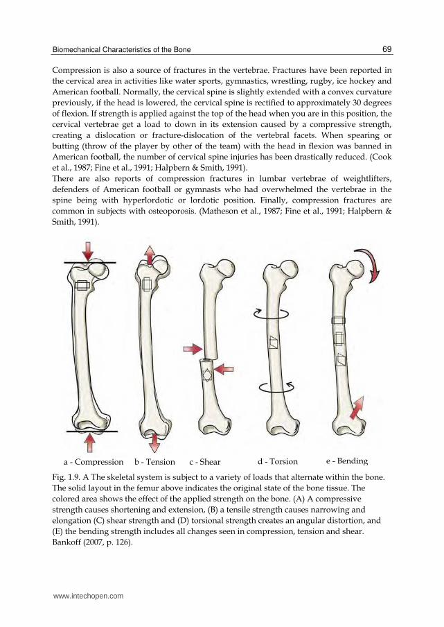
Fig. 1.9. A The skeletal system is subject to a variety of loads that alternate within the bone.
The solid layout in the femur above indicates the original state of the bone tissue. The
colored area shows the effect of the applied strength on the bone. (A) A compressive
strength causes shortening and extension, (B) a tensile strength causes narrowing and
elongation (C) shear strength and (D) torsional strength creates an angular distortion, and
(E) the bending strength includes all changes seen in compression, tension and shear.
Bankoff (2007, p. 126).
a - Compression b - Tension c - Shear d - Torsion e - Bending
www.intechopen.com
Human Musculoskeletal Biomechanics
70
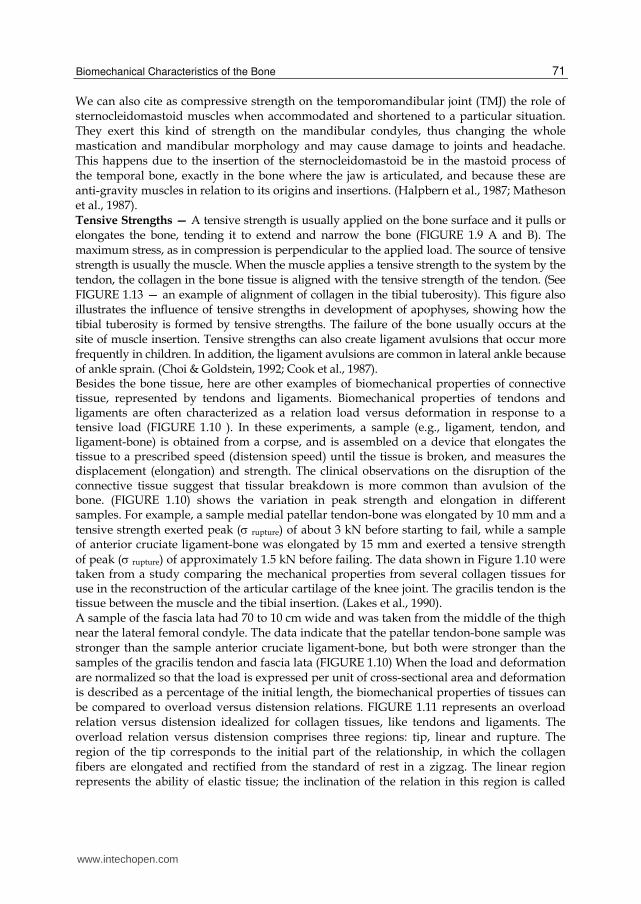
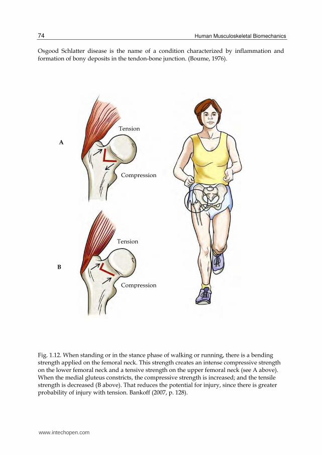
Spondylolysis may occur and a stress fracture of the vertebrae interarticular part. Specific weight lifting that have high incidence of this fracture are the clean and jerk (direct weight lifting from the ground up above the head). It also occurs in gymnasts and is associated with positions of extreme extension of the lumbar vertebrae region. (Matheson et al., 1987). A compressive strength on the hip joint can increase or decrease the potential of femoral neck injury. The hip joint needs to absorb compressive strengths of approximately 3-7 times the body weight during walking. Compressive strengths are over 15 to 20 times the body weight in the jump. In a normal standing posture, the hip joint takes about one third of body weight if the two members are on the ground. This creates large compressive strengths on the lower portion of the femoral neck and a large traction strength or tension on the upper portion of femur neck. FIGURE 1.12 shows how this happens as the body pushes down the femoral head, pushing at the base of the femoral neck and tractioning the top of the femoral neck out while creating a bending (Matheson et al., 1987, Jackson, 1990).
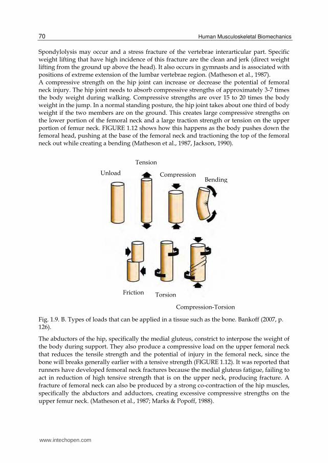
Fig. 1.9. B. Types of loads that can be applied in a tissue such as the bone. Bankoff (2007, p. 126).
The abductors of the hip, specifically the medial gluteus, constrict to interpose the weight of
the body during support. They also produce a compressive load on the upper femoral neck
that reduces the tensile strength and the potential of injury in the femoral neck, since the
bone will breaks generally earlier with a tensive strength (FIGURE 1.12). It was reported that
runners have developed femoral neck fractures because the medial gluteus fatigue, failing to
act in reduction of high tensive strength that is on the upper neck, producing fracture. A
fracture of femoral neck can also be produced by a strong co-contraction of the hip muscles,
specifically the abductors and adductors, creating excessive compressive strengths on the
upper femur neck. (Matheson et al., 1987; Marks & Popoff, 1988).
Unload CompressionBending
Friction Torsion
Compression-Torsion
Tension
www.intechopen.com
Biomechanical Characteristics of the Bone
71
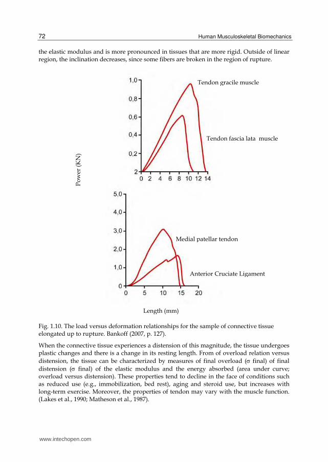
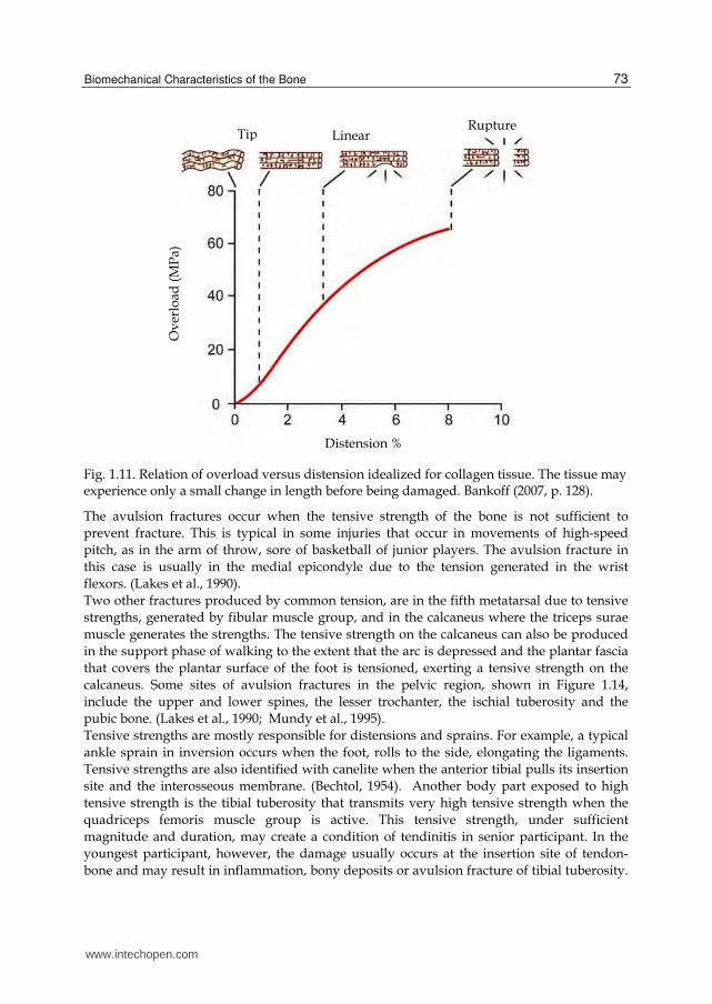
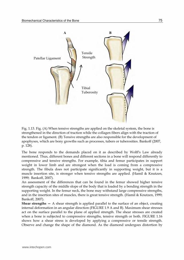
We can also cite as compressive strength on the temporomandibular joint (TMJ) the role of sternocleidomastoid muscles when accommodated and shortened to a particular situation. They exert this kind of strength on the mandibular condyles, thus changing the whole mastication and mandibular morphology and may cause damage to joints and headache. This happens due to the insertion of the sternocleidomastoid be in the mastoid process of the temporal bone, exactly in the bone where the jaw is articulated, and because these are anti-gravity muscles in relation to its origins and insertions. (Halpbern et al., 1987; Matheson et al., 1987). Tensive Strengths — A tensive strength is usually applied on the bone surface and it pulls or elongates the bone, tending it to extend and narrow the bone (FIGURE 1.9 A and B). The maximum stress, as in compression is perpendicular to the applied load. The source of tensive strength is usually the muscle. When the muscle applies a tensive strength to the system by the tendon, the collagen in the bone tissue is aligned with the tensive strength of the tendon. (See FIGURE 1.13 — an example of alignment of collagen in the tibial tuberosity). This figure also illustrates the influence of tensive strengths in development of apophyses, showing how the tibial tuberosity is formed by tensive strengths. The failure of the bone usually occurs at the site of muscle insertion. Tensive strengths can also create ligament avulsions that occur more frequently in children. In addition, the ligament avulsions are common in lateral ankle because of ankle sprain. (Choi & Goldstein, 1992; Cook et al., 1987). Besides the bone tissue, here are other examples of biomechanical properties of connective tissue, represented by tendons and ligaments. Biomechanical properties of tendons and ligaments are often characterized as a relation load versus deformation in response to a tensive load (FIGURE 1.10 ). In these experiments, a sample (e.g., ligament, tendon, and ligament-bone) is obtained from a corpse, and is assembled on a device that elongates the tissue to a prescribed speed (distension speed) until the tissue is broken, and measures the displacement (elongation) and strength. The clinical observations on the disruption of the connective tissue suggest that tissular breakdown is more common than avulsion of the bone. (FIGURE 1.10) shows the variation in peak strength and elongation in different samples. For example, a sample medial patellar tendon-bone was elongated by 10 mm and a tensive strength exerted peak ( rupture) of about 3 kN before starting to fail, while a sample of anterior cruciate ligament-bone was elongated by 15 mm and exerted a tensive strength of peak ( rupture) of approximately 1.5 kN before failing. The data shown in Figure 1.10 were taken from a study comparing the mechanical properties from several collagen tissues for use in the reconstruction of the articular cartilage of the knee joint. The gracilis tendon is the tissue between the muscle and the tibial insertion. (Lakes et al., 1990). A sample of the fascia lata had 70 to 10 cm wide and was taken from the middle of the thigh near the lateral femoral condyle. The data indicate that the patellar tendon-bone sample was stronger than the sample anterior cruciate ligament-bone, but both were stronger than the samples of the gracilis tendon and fascia lata (FIGURE 1.10) When the load and deformation are normalized so that the load is expressed per unit of cross-sectional area and deformation is described as a percentage of the initial length, the biomechanical properties of tissues can be compared to overload versus distension relations. FIGURE 1.11 represents an overload relation versus distension idealized for collagen tissues, like tendons and ligaments. The overload relation versus distension comprises three regions: tip, linear and rupture. The region of the tip corresponds to the initial part of the relationship, in which the collagen fibers are elongated and rectified from the standard of rest in a zigzag. The linear region represents the ability of elastic tissue; the inclination of the relation in this region is called
www.intechopen.com
Human Musculoskeletal Biomechanics
72
the elastic modulus and is more pronounced in tissues that are more rigid. Outside of linear region, the inclination decreases, since some fibers are broken in the region of rupture.
Fig. 1.10. The load versus deformation relationships for the sample of connective tissue elongated up to rupture. Bankoff (2007, p. 127).
When the connective tissue experiences a distension of this magnitude, the tissue undergoes plastic changes and there is a change in its resting length. From of overload relation versus
distension, the tissue can be characterized by measures of final overload ( final) of final
distension ( final) of the elastic modulus and the energy absorbed (area under curve; overload versus distension). These properties tend to decline in the face of conditions such as reduced use (e.g., immobilization, bed rest), aging and steroid use, but increases with long-term exercise. Moreover, the properties of tendon may vary with the muscle function. (Lakes et al., 1990; Matheson et al., 1987).
Tendon fascia lata muscle
Tendon gracile muscle P
ow
er (
KN
)
Medial patellar tendon
Anterior Cruciate Ligament
Length (mm)
www.intechopen.com
Biomechanical Characteristics of the Bone
73
Fig. 1.11. Relation of overload versus distension idealized for collagen tissue. The tissue may experience only a small change in length before being damaged. Bankoff (2007, p. 128).
The avulsion fractures occur when the tensive strength of the bone is not sufficient to
prevent fracture. This is typical in some injuries that occur in movements of high-speed
pitch, as in the arm of throw, sore of basketball of junior players. The avulsion fracture in
this case is usually in the medial epicondyle due to the tension generated in the wrist
flexors. (Lakes et al., 1990).
Two other fractures produced by common tension, are in the fifth metatarsal due to tensive
strengths, generated by fibular muscle group, and in the calcaneus where the triceps surae
muscle generates the strengths. The tensive strength on the calcaneus can also be produced
in the support phase of walking to the extent that the arc is depressed and the plantar fascia
that covers the plantar surface of the foot is tensioned, exerting a tensive strength on the
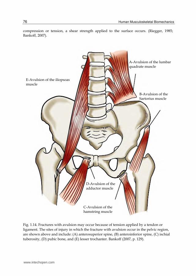
calcaneus. Some sites of avulsion fractures in the pelvic region, shown in Figure 1.14,
include the upper and lower spines, the lesser trochanter, the ischial tuberosity and the
pubic bone. (Lakes et al., 1990; Mundy et al., 1995).
Tensive strengths are mostly responsible for distensions and sprains. For example, a typical
ankle sprain in inversion occurs when the foot, rolls to the side, elongating the ligaments.
Tensive strengths are also identified with canelite when the anterior tibial pulls its insertion
site and the interosseous membrane. (Bechtol, 1954). Another body part exposed to high
tensive strength is the tibial tuberosity that transmits very high tensive strength when the
quadriceps femoris muscle group is active. This tensive strength, under sufficient
magnitude and duration, may create a condition of tendinitis in senior participant. In the
youngest participant, however, the damage usually occurs at the insertion site of tendon-
bone and may result in inflammation, bony deposits or avulsion fracture of tibial tuberosity.
RuptureLinear Tip
Ov
erlo
ad (
MP
a)
Distension %
www.intechopen.com
Human Musculoskeletal Biomechanics
74
Osgood Schlatter disease is the name of a condition characterized by inflammation and
formation of bony deposits in the tendon-bone junction. (Boume, 1976).
Fig. 1.12. When standing or in the stance phase of walking or running, there is a bending strength applied on the femoral neck. This strength creates an intense compressive strength on the lower femoral neck and a tensive strength on the upper femoral neck (see A above). When the medial gluteus constricts, the compressive strength is increased; and the tensile strength is decreased (B above). That reduces the potential for injury, since there is greater probability of injury with tension. Bankoff (2007, p. 128).
Tension
Compression
Tension
Compression
A
B
www.intechopen.com
Biomechanical Characteristics of the Bone
75
Fig. 1.13. Fig. (A) When tensive strengths are applied on the skeletal system, the bone is strengthened in the direction of traction while the collagen fibers align with the traction of the tendon or ligament. (B) Tensive strengths are also responsible for the development of apophyses, which are bony growths such as processes, tubers or tuberosities. Bankoff (2007, p. 128).
The bone responds to the demands placed on it as described by Wolff's Law already mentioned. Thus, different bones and different sections in a bone will respond differently to compressive and tensive strengths. For example, tibia and femur participates in support weight in lower limb and are strongest when the load is coming from a compressive strength. The fibula does not participate significantly in supporting weight, but it is a muscle insertion site, is stronger when tensive strengths are applied. (Hamil & Knutzen, 1999; Bankoff, 2007). An assessment of the differences that can be found in the femur showed higher tensive strength capacity of the middle slope of the body that is loaded by a bending strength in the supporting weight. In the femur neck, the bone may withstand large compressive strengths, and in the insertion sites of muscles, there is great tensive strength. (Hamil & Knutzen, 1999; Bankoff, 2007). Shear strengths — A shear strength is applied parallel to the surface of an object, creating internal deformation in an angular direction (FIGURE 1.9 A and B). Maximum shear stresses act on the surface parallel to the plane of applied strength. The shear stresses are created when a bone is subjected to compressive strengths, tensive strength or both. FIGURE 1.16 shows how a shear stress is developed by applying a compressive or tensile strength. Observe and change the shape of the diamond. As the diamond undergoes distortion by
B A
Patellar Ligament
Tensile Strength
Tibial Tuberosity
www.intechopen.com
Human Musculoskeletal Biomechanics
76
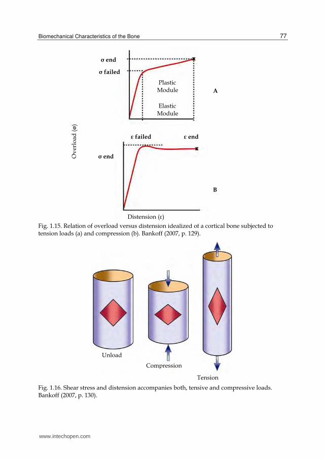
compression or tension, a shear strength applied to the surface occurs. (Riegger, 1985; Bankoff, 2007).
Fig. 1.14. Fractures with avulsion may occur because of tension applied by a tendon or
ligament. The sites of injury in which the fracture with avulsion occur in the pelvic region,
are shown above and include: (A) anterosuperior spine, (B) anteroinferior spine, (C) ischial
tuberosity, (D) pubic bone, and (E) lesser trochanter. Bankoff (2007, p. 129).
A-Avulsion of the lumbar quadrate muscle
B-Avulsion of the Sartorius muscle
D-Avulsion of the adductor muscle
C-Avulsion of the hamstring muscle
E-Avulsion of the iliopsoas muscle
www.intechopen.com
Biomechanical Characteristics of the Bone
77
Fig. 1.15. Relation of overload versus distension idealized of a cortical bone subjected to tension loads (a) and compression (b). Bankoff (2007, p. 129).
Fig. 1.16. Shear stress and distension accompanies both, tensive and compressive loads. Bankoff (2007, p. 130).
Distension (ε)
ε end
Plastic Module
Elastic Module
σ end
σ failed
ε failed
σ end
A
B
Unload
Compression
Tension
Ov
erlo
ad (σ)
www.intechopen.com
Human Musculoskeletal Biomechanics
78
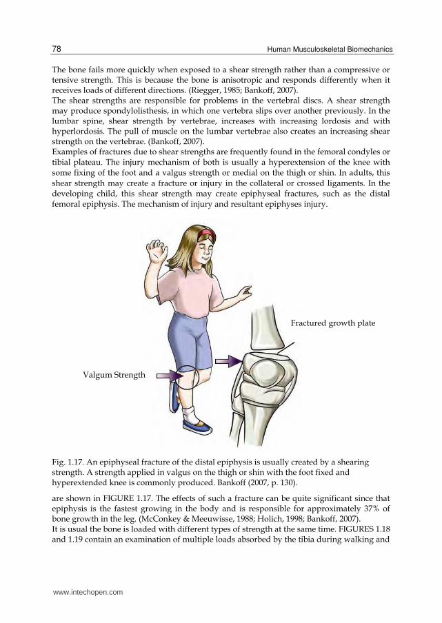
The bone fails more quickly when exposed to a shear strength rather than a compressive or tensive strength. This is because the bone is anisotropic and responds differently when it receives loads of different directions. (Riegger, 1985; Bankoff, 2007). The shear strengths are responsible for problems in the vertebral discs. A shear strength may produce spondylolisthesis, in which one vertebra slips over another previously. In the lumbar spine, shear strength by vertebrae, increases with increasing lordosis and with hyperlordosis. The pull of muscle on the lumbar vertebrae also creates an increasing shear strength on the vertebrae. (Bankoff, 2007). Examples of fractures due to shear strengths are frequently found in the femoral condyles or
tibial plateau. The injury mechanism of both is usually a hyperextension of the knee with
some fixing of the foot and a valgus strength or medial on the thigh or shin. In adults, this
shear strength may create a fracture or injury in the collateral or crossed ligaments. In the
developing child, this shear strength may create epiphyseal fractures, such as the distal
femoral epiphysis. The mechanism of injury and resultant epiphyses injury.
Fig. 1.17. An epiphyseal fracture of the distal epiphysis is usually created by a shearing strength. A strength applied in valgus on the thigh or shin with the foot fixed and hyperextended knee is commonly produced. Bankoff (2007, p. 130).
are shown in FIGURE 1.17. The effects of such a fracture can be quite significant since that epiphysis is the fastest growing in the body and is responsible for approximately 37% of bone growth in the leg. (McConkey & Meeuwisse, 1988; Holich, 1998; Bankoff, 2007). It is usual the bone is loaded with different types of strength at the same time. FIGURES 1.18 and 1.19 contain an examination of multiple loads absorbed by the tibia during walking and
Fractured growth plate
Valgum Strength
www.intechopen.com
Biomechanical Characteristics of the Bone
79
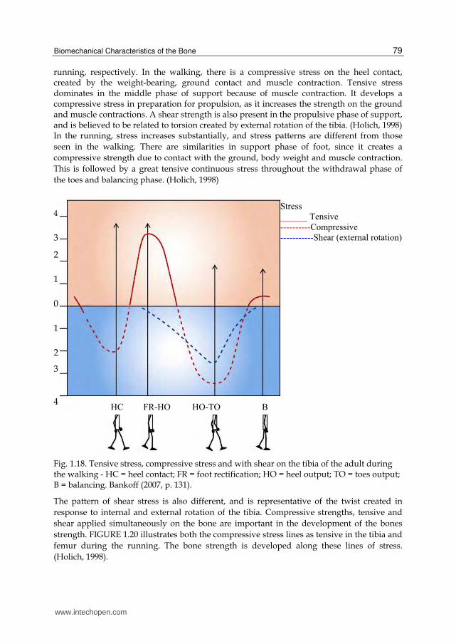
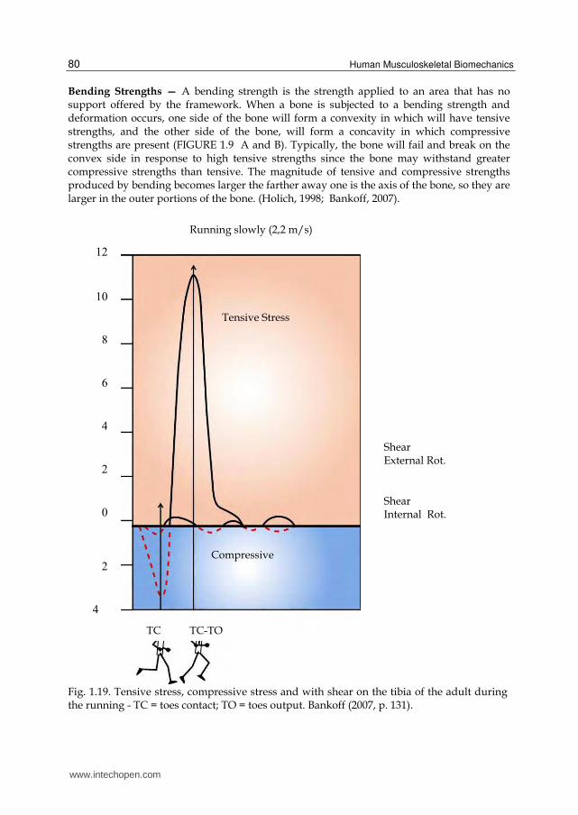
running, respectively. In the walking, there is a compressive stress on the heel contact, created by the weight-bearing, ground contact and muscle contraction. Tensive stress dominates in the middle phase of support because of muscle contraction. It develops a compressive stress in preparation for propulsion, as it increases the strength on the ground and muscle contractions. A shear strength is also present in the propulsive phase of support, and is believed to be related to torsion created by external rotation of the tibia. (Holich, 1998) In the running, stress increases substantially, and stress patterns are different from those
seen in the walking. There are similarities in support phase of foot, since it creates a
compressive strength due to contact with the ground, body weight and muscle contraction.
This is followed by a great tensive continuous stress throughout the withdrawal phase of
the toes and balancing phase. (Holich, 1998)
Fig. 1.18. Tensive stress, compressive stress and with shear on the tibia of the adult during the walking - HC = heel contact; FR = foot rectification; HO = heel output; TO = toes output; B = balancing. Bankoff (2007, p. 131).
The pattern of shear stress is also different, and is representative of the twist created in
response to internal and external rotation of the tibia. Compressive strengths, tensive and
shear applied simultaneously on the bone are important in the development of the bones
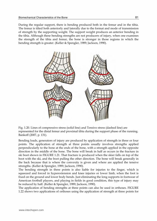
strength. FIGURE 1.20 illustrates both the compressive stress lines as tensive in the tibia and
femur during the running. The bone strength is developed along these lines of stress.
(Holich, 1998).
www.intechopen.com
Human Musculoskeletal Biomechanics
80
Bending Strengths — A bending strength is the strength applied to an area that has no support offered by the framework. When a bone is subjected to a bending strength and deformation occurs, one side of the bone will form a convexity in which will have tensive strengths, and the other side of the bone, will form a concavity in which compressive strengths are present (FIGURE 1.9 A and B). Typically, the bone will fail and break on the convex side in response to high tensive strengths since the bone may withstand greater compressive strengths than tensive. The magnitude of tensive and compressive strengths produced by bending becomes larger the farther away one is the axis of the bone, so they are larger in the outer portions of the bone. (Holich, 1998; Bankoff, 2007).
Fig. 1.19. Tensive stress, compressive stress and with shear on the tibia of the adult during the running - TC = toes contact; TO = toes output. Bankoff (2007, p. 131).
www.intechopen.com
Biomechanical Characteristics of the Bone
81
During the regular support, there is bending produced both in the femur and in the tibia. The femur is tilted both anteriorly and laterally due to the format and mode of transmission of strength by the supporting weight. The support weight produces an anterior bending in the tibia. Although these bending strengths are not producers of injury, when one examines the strength of the tibia and femur, the bone is stronger in those regions in which the bending strength is greater. (Keller & Spengler, 1989; Jackson, 1990).
Fig. 1.20. Lines of compressive stress (solid line) and Tensive stress (dashed line) are represented for the distal femur and proximal tibia during the support phase of the running. Bankoff (2007, p. 131).
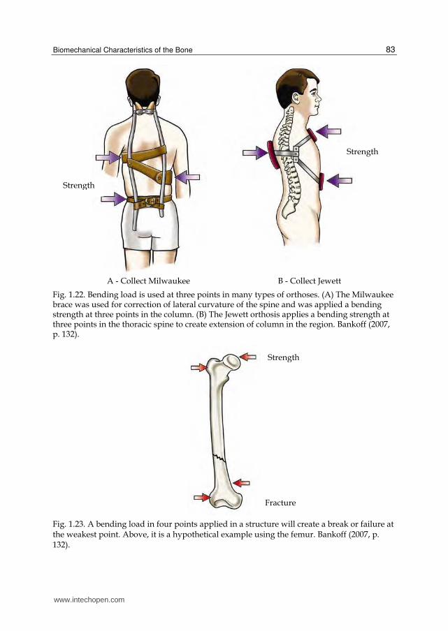
Bending loads, generators of injury are produced by application of strength in three or four points. The application of strength at three points usually involves strengths applied perpendicularly to the bone at the ends of the bone, with a strength applied in the opposite direction in the middle of the bone. The bone will break in half as occurs in the fracture in ski boot shown in FIGURE 1.21. That fracture is produced when the skier falls on top of the boot with the ski, and the boot pulling the other direction. The bone will break generally in the back because that is where the convexity is given and where are applied the tensive strengths. (Keller & Spengler, 1989; Jackson, 1990). The bending strength in three points is also liable for injuries to the finger, which is squeezed and forced in hyperextension and knee injuries or lower limb, when the foot is fixed on the ground and lower body bends. Just eliminating the long supports in footwear of American football players, and playing in fields in good condition, this type of injury may be reduced by half. (Keller & Spengler, 1989; Jackson, 1990). The application of bending strengths at three points can also be used in orthoses. FIGURE 1.22 shows two applications of orthoses using the application of strength at three points for
www.intechopen.com
Human Musculoskeletal Biomechanics
82
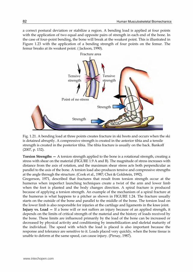
a correct postural deviation or stabilize a region. A bending load is applied at four points with the application of two equal and opposite pairs of strength in each end of the bone. In the case of four-point bending, the bone will break at the weakest point. This is illustrated in Figure 1.23 with the application of a bending strength of four points on the femur. The femur breaks at its weakest point. ( Jackson, 1990).
Fig. 1.21. A bending load at three points creates fracture in ski boots and occurs when the ski is detained abruptly. A compressive strength is created in the anterior tibia and a tensile strength is created in the posterior tibia. The tibia fracture is usually on the back. Bankoff (2007, p. 132).
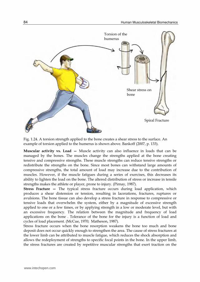
Torsion Strengths — A torsion strength applied to the bone is a rotational strength, creating a stress with shear on the material (FIGURE 1.9 A and B). The magnitude of stress increases with distance from the axis of rotation, and the maximum shear stress acts both perpendicular as parallel to the axis of the bone. A torsion load also produces tensive and compressive strengths at the angle through the structure. (Cook et al., 1987; Choi & Goldstein, 1992). Gregerson, 1971, described that fractures that result from torsion strength occur at the humerus when imperfect launching techniques create a twist of the arm and lower limb when the foot is planted and the body changes direction. A spiral fracture is produced because of applying a torsion strength. An example of the mechanism of a spiral fracture at the humerus is what happens to a pitcher as shown in FIGURE 1.24. The fracture usually starts on the outside of the bone and parallel to the middle of the bone. The torsion load on the lower limb is also responsible for injuries at the cartilage and ligaments in the knee joint. Injury vs. Load — If a bone will or not suffers an injury because of an applied strength, it depends on the limits of critical strength of the material and the history of loads received by the bone. These limits are influenced primarily by the load of the bone can be increased or decreased by physical activity and conditioning by immobilization and skeletal maturity of the individual. The speed with which the load is placed is also important because the response and tolerance are sensitive to it. Loads placed very quickly, when the bone tissue is unable to deform at the same speed, can cause injury. (Pirnay, 1987).
Tensive strength
Fracture area
Tensive strength
Strength
Point of no stress
Strength
www.intechopen.com
Biomechanical Characteristics of the Bone
83
A - Collect Milwaukee B - Collect Jewett
Fig. 1.22. Bending load is used at three points in many types of orthoses. (A) The Milwaukee brace was used for correction of lateral curvature of the spine and was applied a bending strength at three points in the column. (B) The Jewett orthosis applies a bending strength at three points in the thoracic spine to create extension of column in the region. Bankoff (2007, p. 132).
Fig. 1.23. A bending load in four points applied in a structure will create a break or failure at the weakest point. Above, it is a hypothetical example using the femur. Bankoff (2007, p. 132).
Strength
Strength
Strength
Fracture
www.intechopen.com
Human Musculoskeletal Biomechanics
84
Fig. 1.24. A torsion strength applied to the bone creates a shear stress to the surface. An example of torsion applied to the humerus is shown above. Bankoff (2007, p. 133).
Muscular activity vs. Load — Muscle activity can also influence in loads that can be
managed by the bones. The muscles change the strengths applied at the bone creating
tensive and compressive strengths. These muscle strengths can reduce tensive strengths or
redistribute the strengths on the bone. Since most bones can withstand large amounts of
compressive strengths, the total amount of load may increase due to the contribution of
muscles. However, if the muscle fatigues during a series of exercises, this decreases its
ability to lighten the load on the bone. The altered distribution of stress or increase in tensile
strengths makes the athlete or player, prone to injury. (Pirnay, 1987).
Stress Fracture — The typical stress fracture occurs during load application, which produces a shear distension or tension, resulting in lacerations, fractures, ruptures or avulsions. The bone tissue can also develop a stress fracture in response to compressive or tensive loads that overwhelm the system, either by a magnitude of excessive strength applied to one or a few times, or by applying strength in a low or moderate level, but with an excessive frequency. The relation between the magnitude and frequency of load applications on the bone . Tolerance of the bone for the injury is a function of load and cycles of load placement. (McCue, 1970; Matheson, 1987). Stress fracture occurs when the bone resorption weakens the bone too much and bone deposit does not occur quickly enough to strengthen the area. The cause of stress fractures at the lower limb can be attributed to muscle fatigue, which reduces the shock absorption and allows the redeployment of strengths to specific focal points in the bone. In the upper limb, the stress fractures are created by repetitive muscular strengths that exert traction on the
Torsion of the humerus
Shear stress on bone
Spiral Fracture
www.intechopen.com
Biomechanical Characteristics of the Bone
85
bones. This type of fracture responds for 10% of all injuries in athletes. (McCue, 1970; Matheson, 1987).
4. Conclusion
The research in bone biomechanics mentioned in this section contributed to show the importance of this area of study and brought brief discussions on the bone tissue and its incorporation in the biomechanical aspect of human skeletal and locomotor system. The information contained in this study by the authors was a cited research and placed the bone tissue (histology, anatomy, biomechanics and kinesiology) as a material adaptive level of loads.
5. Acknowledgments
To the researchers cited in this section for scientific contributions on bone biomechanical considerations: To the Espaço da Escrita from the University of Campinas for their contribution in the process of translating the text. To the Graduate School of Physical Education in particular to Prof. Antonio Carlos de Moraes. Prof. Dr. Carlos Aparecido Zamai aid in the development and technical preparation of the text.
6. References
Alberts, B. et al. (1994). Molecular biology of the cell. Garland Press, 3rd ed.
Bankoff, A.D.P. (2007). Morfologia e Cinesiologia Aplicada ao Movimento Humano. Editora
Guanabara Koogan, Rio de Janeiro- Brasil.
Bechtol, C.O. (1954). Grip test. J. Bone Joint Surg., 36-A, 820-824.
Boume, G.H. (editor). (1976). The biochemistry and physiology of bone. 2nd ed. 4 vols.
Academic Press.
Choi, K. & Goldstein, S.A. (1992). A comparison of the fatigue behavior of human trabeculae
and cortical bone tissue. Journal Biomechanics, 25: 1371.
Cook, S.D. et al. (1987). Trabeculae bone density and menstrual function in women runners.
The American Journal of Sports Medicine.15: 503.
Egan, J.M. (1987). A constitutive model for the mechanical behavior of soft connective
tissues. Journal of Biomechanics. 20: 681-692.
Fine, K.M.; Vegso, J.J.; Sennett, B., & Torg, J.S. (1991). Prevention of cervical spine injuries in
football. The Physician and Sports Medicine.Vol 19 (10): 54-64.
Gregerson, H.N. (1971). Fractures of the Humerus from Muscular Violence. Acta Orthop.
Scand., 42, 506-512.
Halpbern, B.C., & Smith, A. D. (1991). Catching the cause of low back pain. The Physician
and Sports Medicine. Vol. 19(6): 71079.
Halpbern, B., et al. (1987). High school football injuries: Identifying the risk factors. The
American Journal of Sports Medicine. 15: 316.
www.intechopen.com

Human Musculoskeletal Biomechanics
86
Hamill, J.; & Knutzen, K.M. (1999). Bases biomecânicas do movimento humano. São Paulo:
Manole
Hay, E.D. (editor). (1982). Cell biology of extracellular matrix. Plenum.
Hoffman, A.H.; & Grigg, P. (1989). Measurement of joint capsule tissue loading in the cat
knee using calibrated mechano-receptors. Journal of Biomechanics. 22: 787-791.
Holtrop, M.E. (1975). The ultra structure of bone. Ann Clin Lab Sci, 5:264.
Holick, M.F. (1998). Perspective on the impact of weightlessness on calcium and bone
metabolism. Bone, New York. v.22, n.5, p.105-111.
Jackson, D.L. (1990). Stress fracture of the femur. The Physician and Sports Medicine. v. 9,
(7), pp. 39-44
Junqueira, L.C.; & Carneiro, J. (1999). Histologia básica. 9 ed, Rio de Janeiro: Guanabara
Koogan.
Junqueira, L.C.; & Carneiro, J. (1997). Biologia celular e molecular. 6 ed. Rio de Janeiro:
Guanabara Koogan.
Keller, T.S.; Spengler, D.M. (1989). Regulation of bone stress and strain in the immature and
mature rat femur. Journal of Biomechanics. 22:1115-1127.
Lakes, R.S.; Nakamura, S.; Behiri, J.C. E.; & Bonfield, W. (1990). Fracture mechanics of bone
with short cracks. Journal of Biomechanics. 23:967-975.
Marks Jr, S.C.; & Popoff, S.N. (1988). Bone cell biology the regulation of development
structure, and function in the skeleton. Amer J Anat 183:1.
McConkey, J.P., & Meeuwisse, W. (1988). Tibial plateau fractures in alpine skiing. The
American Journal of Sports Medicine. 16: 159-164.
Matheson, G.O. et al. (1987). Stress fractures in athletes. The American Journal of Sports
Medicine. 15:46-58.
McCue, F.C. (1970). Athletic Injuries of the Proximal Interphalangeal Joint Requiring
Surgical Treatment. J. Bone Joint Surg., 52-A, 937-956.
Mundy, G.R. et al. (1995). The effects of cytokines and growth factors on osteoblastic cells.
Bone. 17:71.
Pirnay, F.M. et al. (1987). Bone mineral contend and physical activity. International Journal
Sport Medicine, 8: 331.
Riegger, C.L. (1985). Mechanical properties of bone. Ln: Orthopaedic and Sports Physical
Therapy. Edited by J.A. Gouldand G.J. Davies. St. Louis, C.V. Mosby Co, 3-49.
Schaffler, M.B.; & Burr, D.B. (1988). Stiffness of compact bone: Effects of porosity and
density. Journal of Biomechanics. 21:13-16.
Shipman, P., Walker, A.; & Bichell, D. (1985). The Human Skeleton. Cambridge, Harvard
University Press.
www.intechopen.com
Human Musculoskeletal BiomechanicsEdited by Dr. Tarun Goswami
ISBN 978-953-307-638-6Hard cover, 244 pagesPublisher InTechPublished online 05, January, 2012Published in print edition January, 2012
InTech EuropeUniversity Campus STeP Ri Slavka Krautzeka 83/A 51000 Rijeka, Croatia Phone: +385 (51) 770 447 Fax: +385 (51) 686 166www.intechopen.com
InTech ChinaUnit 405, Office Block, Hotel Equatorial Shanghai No.65, Yan An Road (West), Shanghai, 200040, China
Phone: +86-21-62489820 Fax: +86-21-62489821
This book covers many aspects of human musculoskeletal biomechanics. As the title represents, aspects offorces, motion, kinetics, kinematics, deformation, stress, and strain are examined for a range of topics such ashuman muscles, skeleton, and vascular biomechanics independently or in the presence of devices. Topicsrange from image processing to interpret range of motion and/or diseases, to subject specifictemporomandibular joint, spinal units, braces to control scoliosis, hand functions, spine anthropometricanalyses along with finite element analyses. Therefore, this book will be valuable to students at introductorylevel to researchers at MS and PhD level searching for science of specific muscle/vascular to skeletalbiomechanics. This book will be an ideal text to keep for graduate students in biomedical engineering since it isavailable for free, students may want to make use of this opportunity. Those that are interested to participatein the future edition of this book, on the same topic, as a contributor please feel free to contact the author.
How to referenceIn order to correctly reference this scholarly work, feel free to copy and paste the following:
Antonia Dalla Pria Bankoff (2012). Biomechanical Characteristics of the Bone, Human MusculoskeletalBiomechanics, Dr. Tarun Goswami (Ed.), ISBN: 978-953-307-638-6, InTech, Available from:http://www.intechopen.com/books/human-musculoskeletal-biomechanics/biomechanical-characteristics-of-the-bone

© 2012 The Author(s). Licensee IntechOpen. This is an open access articledistributed under the terms of the Creative Commons Attribution 3.0License, which permits unrestricted use, distribution, and reproduction inany medium, provided the original work is properly cited.