Embed Size (px)
Citation preview
Research ArticleBiomechanical Effect of Orthodontic Treatment of CanineRetraction by Using Metallic Orthodontic Mini-Implant (OMI)Covered with Various Angles of Revolving Cap
Kuson Tuntiwong,1 Jui-Ting Hsu,1,2 Shih-Guang Yang,3 Jian-Hong Yu ,1,4
and Heng-Li Huang 1,2
1School of Dentistry, China Medical University, Taichung 40402, Taiwan2Department of Bioinformatics and Medical Engineering, Asia University, Taichung 41354, Taiwan3Master Program for Biomedical Engineering, China Medical University, Taichung 40402, Taiwan4Department of Dentistry, China Medical University Hospital, Taichung 40402, Taiwan
Correspondence should be addressed to Jian-Hong Yu; [email protected] Heng-Li Huang; [email protected]
Received 30 March 2021; Accepted 21 June 2021; Published 12 July 2021
Academic Editor: Antonio Pérez-González
Copyright © 2021 Kuson Tuntiwong et al. This is an open access article distributed under the Creative Commons AttributionLicense, which permits unrestricted use, distribution, and reproduction in any medium, provided the original work isproperly cited.
Objective. This study evaluated the biomechanical effects of a metallic orthodontic mini-implant (OMI) covered with various typesof angled revolving cap on the peri-OMI bone and the canine periodontal ligament (PDL) by finite element (FE) analyses.Materialsand Methods. Three-dimensional FE models included comprised cortical bone and cancellous bone of the maxilla, and the OMIswere created. The forces (0.98N) pulled in both the canine hook and the revolving cap, pulling towards each other in bothdirections as loading conditions. The upper surface of the maxilla was fixed as a boundary condition. Results. The bone stresseswere increasing in the models by using OMI covered with a revolving cap as compared with that in the conventional model (inwhich only the OMI was placed). However, no obvious differences in bone stresses were observed among the models withvarious types of angled revolving cap. The minimum principal strain in the canine PDL was highest for condition 180T,followed by condition 180L. However, the maximum differences in the values between each experimental model and theconventional model were around 5%. Conclusion. This study showed no obvious effects in decreasing or increasing stress/strainin bone and PDL by using various types of angled revolving cap covered metallic mini-implant in orthodontic treatment ofcanine retraction.
1. Introduction
Orthodontic treatment is applied in dentistry for malocclu-sion, which includes tooth crowding, protrusion, and spac-ing. Malalignment and crowding are reportedly present inalmost 15% of adolescents, and affected adults can haveextremely irregular incisors [1]. Tooth extraction is oftennecessary for treating malalignment and crowding. Two tis-sues have major effects on orthodontic tooth movement:the periodontal ligament (PDL) and alveolar bone. For casesof Class II or Class I bimaxillary protrusion, normally, theanterior part of the maxillary teeth should be pulled back-
ward and the tooth angulation should be made parallel tothe same tooth.
Most cases of orthodontic treatment first involve premo-lar extraction followed by canine retraction (CR). An anchor-age is required for such treatment, which refers to theresistance to reaction forces provided by other teeth, palate,head, or neck (via extraoral forces) [2], and an orthodonticmini-implant (OMI) is commonly used [3]. The ideal forcefor translating a canine is typically 150–200 gf. The availabil-ity of a reliable anchorage during space closure is importantwhen performing CR after premolar extraction. OMIs aresuitable for facilitating orthodontic tooth movement due to
HindawiApplied Bionics and BiomechanicsVolume 2021, Article ID 9952392, 8 pageshttps://doi.org/10.1155/2021/9952392
their biocompatibility, small size, and placement utility [4, 5].The placement of an OMI between the roots of the maxillarysecond premolar and first molar for retracting a canine isaimed at avoiding forward movement of the posterior seg-ments of the maxillary arch. However, an OMI can only beplaced between teeth with sufficient bone density and rootclearance [4].
One limitation of the maxilla is that the maxillary sinus isan important vital structure. The revolving cap can be usedwith the OMIs and allows forces to be applied to the cap atdiverse angulations and is particularly advantageous sincean OMI cannot be inserted or position changes by an OMIare greatly restricted in many positions close to vital struc-tures. The revolving cap was constructed from a medical-grade plastic (polycarbonate) material.
The mechanics of orthodontic tooth movement due toremodeling were investigated using finite element (FE) anal-ysis [6]. This technique is popular in orthodontics since itcan reveal internal strains and resolve significantly indefi-nite force systems. [7, 8]. Numerous studies have attemptedto improve the modeling of biological structures, with thatof Cattaneo et al. probably the most important for differentPDL assumptions [7]. Those authors found that makingdifferent assumptions about the PDL markedly influencesthe resulting stress in the ligament. However, modelingapproaches are still necessary since in vivo studies remaininsufficient for investigating biomechanical effects such asstress and strain in PDL.
Therefore, this study used computer-aided design (CAD)and FE analysis to evaluate the effects of various loading sys-tems on the maxillary bone and PDL in cases of CR per-formed using a revolving cap. The objectives of this studyalso included determining the effects of applying forces invarious directions by angulating the revolving cap and evalu-ated the maximum and minimum principal strains in themaxillary canine PDL as well as the equivalent (von Mises)stress in the maxillary bones to fully characterize the biome-chanics of orthodontic CR.
2. Materials and Methods
A series of computed tomography images of the maxilla of anorthodontic patient was obtained from the left upper teeth(canine, second premolar, and first molar) and PDL (Soma-
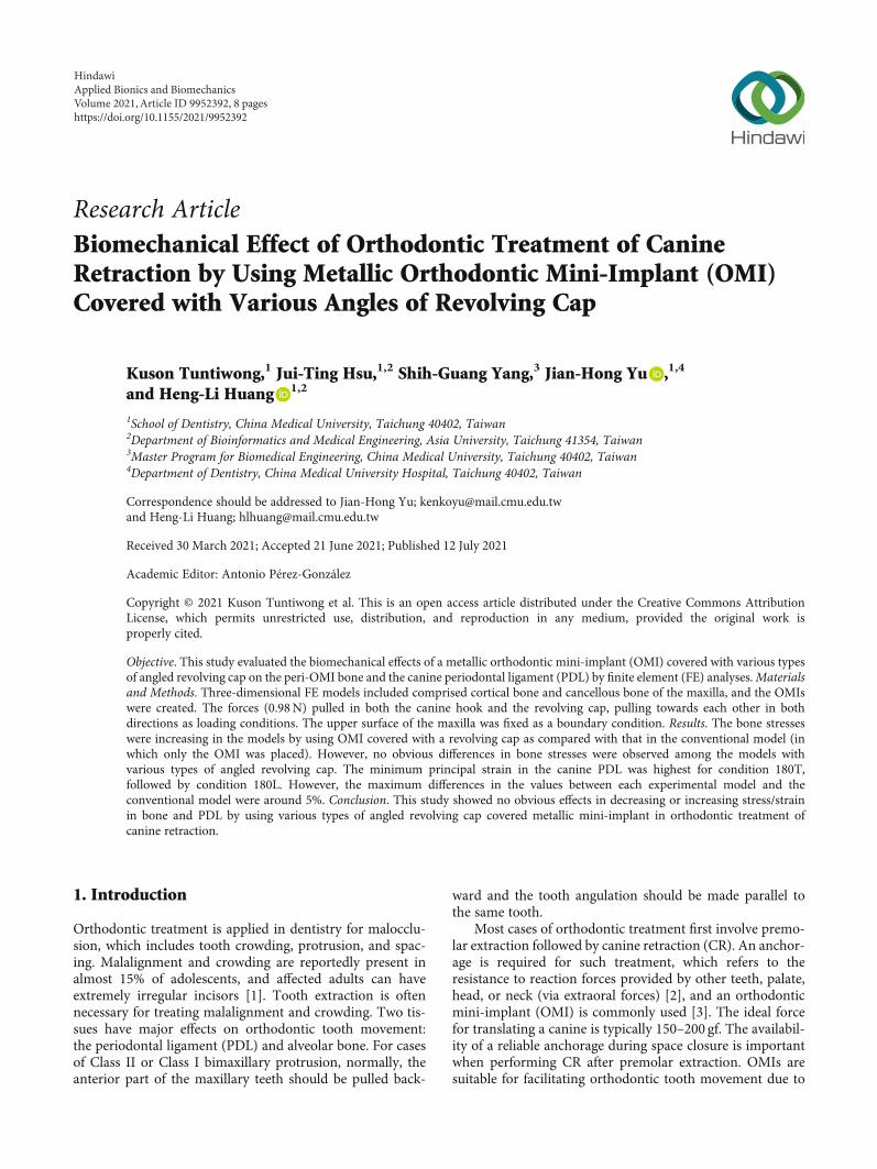
tom Sensation 16, Siemens Medical Solutions, Forchheim,Germany). Adjacent images were separated by 1mm. Thecoordinate data were used by CAD software (SolidWorks2007, SolidWorks, Concord, MA, USA) to generate a three-dimensional solid model of the left maxilla. The PDL tissuewas modeled as a thin enclosure around the dental root withan average thickness of approximately 0.25mm [9](Figure 1). The cortical bone was modeled as being 2mmthick, with underlying cancellous bone. The maxilla was cutin half and had manipulated alveolar sockets, and a modelof the tooth was also created.
A model of a 10mm long OMI with a diameter of 1.6mm was constructed manually using CAD software (Solid-Works 2007). The OMI was angled 60° from the alveolarridge between the roots of the second premolar and the firstmolar on the buccal side, and it was positioned 1mm fromthe PDL. This location eliminated interference from adjacentroots and was based on the local root anatomy. A subtrac-tion operation was performed to create a hole for the OMIin the maxillary model. The 0.018 in standard nontorqued,nonangulated, edgewise orthodontic canine brackets; molartube; OMI; and revolving cap were modeled manually basedon a typical clinical treatment process. The reconstructedmaxilla, canine, second premolar, first molar, PDL, brackets,OMI, and revolving cap were all modeled using CAD soft-ware (SolidWorks 2007) (Table 1).
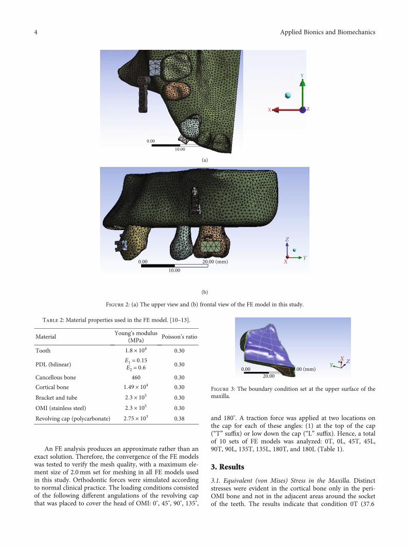
All models were combined using Boolean operations,and files containing the models in IGES format were thenimported into ANSYS Workbench (Swanson Analysis,Huston, PA, USA) to generate the FE model (Figure 2)using 10-node tetrahedral h-elements. Homologous, isotro-pic, and linearly elastic material properties were used forall models except for the PDL, which was included as abilinear elastic material [10–13]. The material propertiesassigned to the FE models are listed in Table 2. In thesimplified model, a 0.98N (100 gf) couple force wasapplied as the loading condition either towards the caninehook or towards the revolving cap (Table 1). The mesio-distal surfaces of the maxilla bone were constrained tozero displacement in the x, y, and z directions as a bound-ary condition. A fixed boundary condition assigned to theupper sectioned surface of the maxillary bone as shown inFigure 3 completed the simulation of natural anatomicconstraints.
X
YZ
(a) (b) (c)
Figure 1: Solid models of the (a) canine, second premolar, and first molar and (b) canine PDL. (c) The PDF was 0.25mm thick.
2 Applied Bionics and Biomechanics
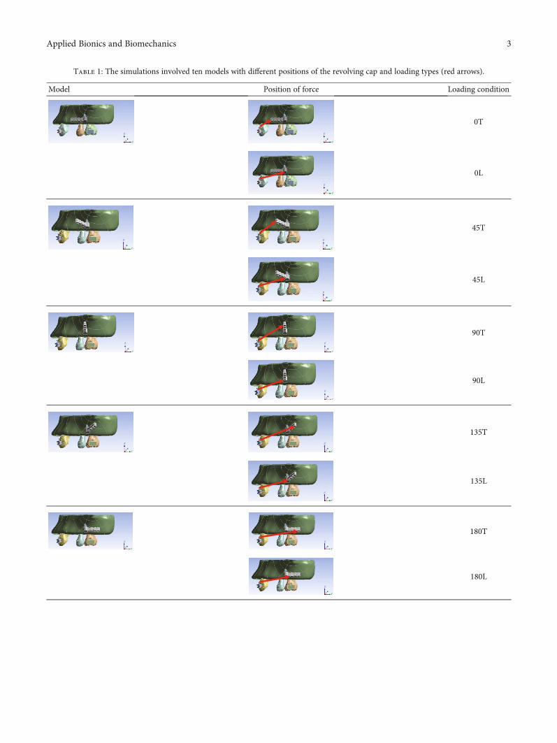
Table 1: The simulations involved ten models with different positions of the revolving cap and loading types (red arrows).
Model Position of force Loading condition
0T
0L
45T
45L
90T
90L
135T
135L
180T
180L
3Applied Bionics and Biomechanics
An FE analysis produces an approximate rather than anexact solution. Therefore, the convergence of the FE modelswas tested to verify the mesh quality, with a maximum ele-ment size of 2.0mm set for meshing in all FE models usedin this study. Orthodontic forces were simulated accordingto normal clinical practice. The loading conditions consistedof the following different angulations of the revolving capthat was placed to cover the head of OMI: 0°, 45°, 90°, 135°,
and 180°. A traction force was applied at two locations onthe cap for each of these angles: (1) at the top of the cap(“T” suffix) or low down the cap (“L” suffix). Hence, a totalof 10 sets of FE models was analyzed: 0T, 0L, 45T, 45L,90T, 90L, 135T, 135L, 180T, and 180L (Table 1).
3. Results
3.1. Equivalent (von Mises) Stress in the Maxilla. Distinctstresses were evident in the cortical bone only in the peri-OMI bone and not in the adjacent areas around the socketof the teeth. The results indicate that condition 0T (37.6
X
0.00
10.00
Y
Z
(a)
X0.0010.00
20.00 (mm) Y
Z
(b)
Figure 2: (a) The upper view and (b) frontal view of the FE model in this study.
Table 2: Material properties used in the FE model. [10–13].
MaterialYoung’s modulus
(MPa)Poisson’s ratio
Tooth 1:8 × 10⁴ 0.30
PDL (bilinear)E1 = 0:15E2 = 0:6 0.30
Cancellous bone 460 0.30
Cortical bone 1:49 × 104 0.30
Bracket and tube 2:3 × 10⁵ 0.30
OMI (stainless steel) 2:3 × 10⁵ 0.30
Revolving cap (polycarbonate) 2:75 × 103 0.38
X
0.0020.00
40.00 (mm)Y
Z
Figure 3: The boundary condition set at the upper surface of themaxilla.
4 Applied Bionics and Biomechanics
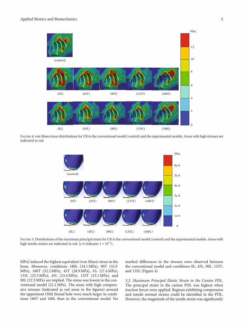
MPa) induced the highest equivalent (vonMises) stress in thebone. Moreover, conditions 180L (34.1MPa), 90T (32.9MPa), 180T (32.2MPa), 45T (28.9MPa), 0 L (27.4MPa),135L (23.5MPa), 45L (23.4MPa), 135T (23.1MPa), and90L (22.5MPa) are implied. The stress was lowest in the con-ventional model (22.1MPa). The areas with high compres-sive stresses (indicated as red areas in the figures) aroundthe uppermost OMI thread hole were much larger in condi-tions 180T and 180L than in the conventional model. No
marked differences in the stresses were observed betweenthe conventional model and conditions 0L, 45L, 90L, 135T,and 135L (Figure 4).
3.2. Maximum Principal Elastic Strain in the Canine PDL.The principal strain in the canine PDL was highest whentraction forces were applied. Regions exhibiting compressiveand tensile normal strains could be identified in the PDL.However, the magnitude of the tensile strain was significantly
(control)
(0T) (45T) (90T) (135T) (180T)
(0L) (45L) (90L) (135L) (180L)
Max.
12
10
8
6
4
2
0
Figure 4: vonMises stress distributions for CR in the conventional model (control) and the experimental models. Areas with high stresses areindicated in red.
(control)
Max
6e-6
5e-6
4e-6
3e-6
2e-6
1e-6
0
(0T) (45T) (90T) (135T) (180T)
(0L) (45L) (90L) (135L) (180L)
Figure 5: Distributions of the maximum principal strain for CR in the conventional model (control) and the experimental models. Areas withhigh tensile strains are indicated in red. (e‐6 indicates 1 ∗ 10−6).
5Applied Bionics and Biomechanics
higher than that of the compressive strain. All dominantprincipal strains were clearly evident at the mesiolabial mar-gin of the PDL, with no marked differences in the strain dis-tribution between the models (Figure 5). The strain was thehighest in condition 0L (14.9μstrain), followed by conditions0T (14.8μstrain), 45L and 90L (14.7μstrain), and 45T, 90T,135T, and 135L (14.6μstrain). The maximum strain in theconventional model was 14.3μstrain. The peak strain waslower in conditions 180L (14.2μstrain) and 180T (13.9μstrain) than in the conventional model. The difference inthe values between each experimental model and the conven-tional model did not exceed 5%.
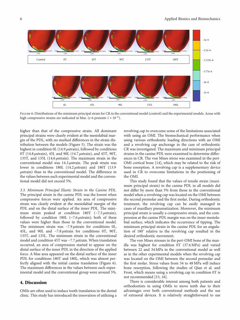
3.3. Minimum Principal Elastic Strain in the Canine PDL.The principal strain in the canine PDL was the lowest whencompressive forces were applied. An area of compressivestrain was clearly evident at the mesiolabial margin of thePDL and on the distal surface of the inner PDL. The mini-mum strain peaked at condition 180T (−7.5μstrain),followed by condition 180L (−7.6μstrain); both of thesevalues were higher than those in the conventional model.The minimum strain was −7.9μstrain for conditions 0L,45L, and 90L and −7.8μstrain for conditions 0T, 90T,135T, and 135L. The minimum strain in the conventionalmodel and condition 45T was −7.7μstrain. When translationoccurred, an area of compression started to appear on thedistal surface of the inner PDL in the direction of the appliedforce. A blue area appeared on the distal surface of the innerPDL for conditions 180T and 180L, which was almost per-fectly aligned with the initial canine translation (Figure 6).The maximum differences in the values between each exper-imental model and the conventional group were around 5%.
4. Discussion
OMIs are often used to induce tooth translation in the dentalclinic. This study has introduced the innovation of utilizing a
revolving cap to overcome some of the limitations associatedwith using an OMI. The biomechanical performance whenusing various orthodontic loading directions with an OMIand a revolving cap anchorage in the case of orthodonticCR was investigated. The maximum and minimum principalstrains in the canine PDL were examined to determine differ-ences in CR. The von Mises stress was examined in the peri-OMI cortical bone [14], which may be related to the risk ofbone resorption. A revolving cap is a supplementary deviceused in CR to overcome limitations in the positioning ofthe OMI.
This study found that the values of tensile strain (maxi-mum principal strain) in the canine PDL in all models didnot differ by more than 5% from those in the conventionalmodel when a revolving cap was located on the OMI betweenthe second premolar and the first molar. During orthodontictreatment, the revolving cap can be easily managed incases of maxillary pneumatization. Moreover, the minimumprincipal strain is usually a compressive strain, and the com-pression at the canine PDL margin was on the inner mesiola-bial surface, which indicates the occurrence of tipping. Theminimum principal strain in the canine PDL for an angula-tion of 180° relative to the revolving cap resulted in thedesired orthodontic movement.
The von Mises stresses in the peri-OMI bone of the max-illa was highest for condition 0T (37.6MPa) and variedbetween 22 and 34MPa in the conventional model as wellas in the other experimental models when the revolving capwas located on the OMI between the second premolar andthe first molar. Stress values from 34 to 48MPa will inducebone resorption, following the studies of Qian et al. andFrost, which means using a revolving cap in condition 0T isnot recommended [15, 16].
There is considerable interest among both patients andorthodontists in using OMIs to move teeth due to theiradvantages over both conventional methods and the useof extraoral devices. It is relatively straightforward to use
Control
0.000 4.000 (mm)2.000
0.000 4.000 (mm)2.000
0.000 4.000 (mm)2.000
0.000 4.000 (mm)2.000
0.000 4.000 (mm)2.000
0.000 4.000 (mm)2.000
0.000 4.000 (mm)2.000
0.000 4.000 (mm)2.000
0.000 4.000 (mm)2.000
0.000 4.000 (mm)2.000
0.000 4.000 (mm)2.000
0T 45T
45L
90T
90L
135T
135L
180T
180L0L
–2e-6
–2.5e-6
–3.125e-6
–3.75e-6
–4e-6
–5e-6
Figure 6: Distributions of the minimum principal strain for CR in the conventional model (control) and the experimental models. Areas withhigh compressive strains are indicated in blue. (e‐6 presents 1 ∗ 10−6).
6 Applied Bionics and Biomechanics
a revolving cap to cover the OMI to facilitate tooth move-ment and hence also the translational mechanics phase oforthodontic treatment. This study showed that coveringmini-implants by a revolving cap increased the peri-OMIbone stress. In addition to the risk of pathologic boneresorption, there is also a possibility of crestal bone resorp-tion based on the high stress values induced in the peri-OMI bone when using the revolving cap under an angula-tion of 0°. This is probably due to the distance from theoriginal force to the revolving cap area, which would resultin higher bone stress. Fortunately, a revolving cap at anangulation of 0° is not used frequently in orthodontictreatments.
This study was subject to a variety of limitations, includ-ing the inherent ones that apply in any modeling study. Amodel can only produce results as accurate as the set ofassumptions that were used to create it, including boundaryconditions, loading conditions, and material properties. Theboundary conditions of the present model included that thetop surface of the maxilla was fixed. The loading conditionsincluded applying load over the revolving cap coveringOMI, which was placed between the second premolar andthe first molar sites. The position of the OMI was set betweenthe root of the second premolar and the first molar. There-fore, the present findings might not apply to other positionsof OMIs and revolving caps.
5. Conclusions
Within the limitations as described above, the findings of thisstudy can be summarized as follows:
(1) No obvious effects in decreasing bone stress wereobserved in all models by using mini-implant(OMI) covered with various angles of the revolvingcap. However, the stress around the top of the OMIthread hole was greatly increased in conditions180T and 180L compared with the conventionalmodel. No obvious differences in the stress in theperi-OMI bone were found between the conventionalmodel and conditions 0L, 45L, 90L, 135T, and 135L
(2) All dominant principal strains were clearly evident atthe mesiolabial margin of the PDL. However, thehighest strain in each experimental model did notdiffer by more than 5% from that in the conventionalmodel. It looks like there are no obvious effects indecreasing or increasing the strain in PDL by usingthe revolving cap in orthodontic treatment of canineretraction
Data Availability
The underlying data can be found through the authors. Any-body who is interested in the data can email the authorsdirectly.
Conflicts of Interest
The authors declare that they have no conflicts of interest.
Authors’ Contributions
Kuson Tuntiwong and Jui-Ting Hsu are equal contributors.
Acknowledgments
This research was supported by the China Medical Univer-sity, Taiwan (CMU109-MF-77).
References
[1] W. Proffit and H. Field, Malocclusion and dentofacial defor-mity in contemporary society, in Contemporary Orthodontics,Mosby, St. Louis, MO, 1993.
[2] D. Roberts-Harry and J. Sandy, “Orthodontics. Part 9: anchor-age control and distal movement,” British Dental Journal,vol. 196, no. 5, pp. 255–263, 2004.
[3] H.-S. Park, S.-M. Bae, H.-M. Kyung, and J.-H. Sung, “Micro-implant anchorage for treatment of skeletal class I bialveolarprotrusion,” Journal of Clinical Orthodontics, vol. 35, no. 7,pp. 417–422, 2001.
[4] H. H. Ammar, P. Ngan, R. J. Crout, V. H. Mucino, and O. M.Mukdadi, “Three-dimensional modeling and finite elementanalysis in treatment planning for orthodontic tooth move-ment,” American Journal of Orthodontics and DentofacialOrthopedics, vol. 139, no. 1, pp. e59–e71, 2011.
[5] M. A. Papadopoulos and F. Tarawneh, “The use of miniscrewimplants for temporary skeletal anchorage in orthodontics: acomprehensive review,” Oral Surgery, Oral Medicine, OralPathology, Oral Radiology, and Endodontics, vol. 103, no. 5,pp. e6–e15, 2007.
[6] S. Mohammed and H. Desai, “Basic concepts of finite elementanalysis and its applications in dentistry: an overview,” Journalof Oral Hygiene & Health, vol. 2, p. 156, 2014.
[7] P. Cattaneo, M. Dalstra, and B. Melsen, “The finite elementmethod: a tool to study orthodontic tooth movement,” Journalof Dental Research, vol. 84, no. 5, pp. 428–433, 2005.
[8] M. Poppe, C. Bourauel, and A. Jäger, “Determination of theelasticity parameters of the human periodontal ligament andthe location of the center of resistance of single-rooted teeth,”Journal of Orofacial Orthopedics, vol. 63, no. 5, pp. 358–370,2002.
[9] E. D. Coolidge, “The thickness of the human periodontalmembrane,” Journal of the American Dental Association(1939), vol. 24, no. 8, pp. 1260–1270, 1937.
[10] Z. Liao, J. Chen, W. Li, M. A. Darendeliler, M. Swain, andQ. Li, “Biomechanical investigation into the role of the peri-odontal ligament in optimising orthodontic force: a finite ele-ment case study,” Archives of Oral Biology, vol. 66, pp. 98–107, 2016.
[11] A. Kawarizadeh, C. Bourauel, and A. Jäger, “Experimental andnumerical determination of initial tooth mobility and materialproperties of the periodontal ligament in rat molar speci-mens,” European Journal of Orthodontics, vol. 25, no. 6,pp. 569–578, 2003.
[12] T.-S. Lin, F.-D. Tsai, C.-Y. Chen, and L.-W. Lin, “Factorialanalysis of variables affecting bone stress adjacent to the ortho-dontic anchorage mini-implant with finite element analysis,”American Journal of Orthodontics and Dentofacial Orthope-dics, vol. 143, no. 2, pp. 182–189, 2013.
[13] M. S. M. Lande, A. Desai, A. Verma, and A. Gaur, “Stress anal-ysis of polycarbonate spur gears for sugarcane juice machine
7Applied Bionics and Biomechanics
using FEA,” International Journal on Recent Technologies inMechanical and Electrical Engineering (IJRMEE), vol. 2,no. 10, pp. 14–19, 2015.
[14] M. Motoyoshi, S. Ueno, K. Okazaki, and N. Shimizu, “Bonestress for a mini-implant close to the roots of adjacent teeth -3D finite element analysis,” International Journal of Oral andMaxillofacial Surgery, vol. 38, no. 4, pp. 363–368, 2009.
[15] L. Qian, M. Todo, Y. Matsushita, and K. Koyano, “Finite ele-ment analysis of bone resorption around dental implant,”Journal of Biomechanical Science and Engineering, vol. 4,no. 3, pp. 365–376, 2009.
[16] H. M. Frost, “Perspectives: bone's mechanical usage windows,”Bone and Mineral, vol. 19, no. 3, pp. 257–271, 1992.
8 Applied Bionics and Biomechanics


![Post-orthodontic retention effectiveness of two types of ... · and fixed retainer bonded only to the lingual surfaces of the lower canines [canine-and-canine retainer])? Analysis](https://img.pdfslide.net/doc/110x75/5fc0cf65e527fc14472449c0/post-orthodontic-retention-effectiveness-of-two-types-of-and-fixed-retainer.jpg)