Embed Size (px)
Citation preview

1
Biomechanical Properties of the Marfan’s Aortic Root and Ascending
Aorta Before and After Personalised External Aortic Root Support
Surgery
S. D. Singha, X. Y. Xu
a,*, J. R. Pepper
b,c, T. Treasure
d, R. H. Mohiaddin
b,c
aDepartment of Chemical Engineering, Imperial College London, South Kensington Campus, London
SW7 2AZ, UK
bRoyal Brompton and Harefield NHS Foundation Trust, Sydney Street, London SW3 6NP, UK
cNational Heart and Lung Institute, Imperial College London, London SW7 2AZ, UK
dClinical Operational Research, University College London, Department of Mathematics, 4 Taviton
Street, London WC1H 0BT, UK
*Corresponding author:
Professor X.Y. Xu
Department of Chemical Engineering
Imperial College London
South Kensington Campus
London SW7 2AZ
Tel: +44 207 594 5588
Fax: +44 207 594 1989
E-mail: [email protected]
2
Abstract
Marfan syndrome is an inherited systemic connective tissue disease which may lead to aortic
root disease causing dilatation, dissection and rupture of the aorta. The standard treatment is a
major operation involving either an artificial valve and aorta or a complex valve repair. More
recently, a personalised external aortic root support (PEARS) has been used to strengthen the
aorta at an earlier stage of the disease avoiding risk of both rupture and major surgery. The
aim of this study was to compare the stress and strain fields of the Marfan aortic root and
ascending aorta before and after insertion of PEARS in order to understand its biomechanical
implications.
Finite element (FE) models were developed using patient-specific aortic geometries
reconstructed from pre and post-PEARS magnetic resonance images in three Marfan patients.
For the post-PEARS model, two scenarios were investigated – a bilayer model where PEARS
and the aortic wall were treated as separate layers, and a single-layer model where PEARS
was incorporated into the aortic wall. The wall and PEARS materials were assumed to be
isotropic, incompressible and linearly elastic. A static load on the inner wall corresponding to
the patients’ pulse pressure was applied.
Results from our FE models with patient-specific geometries show that peak aortic stresses
and displacements before PEARS were located at the sinuses of Valsalva but following
PEARS surgery, these peak values were shifted to the aortic arch, particularly at the interface
between the supported and unsupported aorta. Further studies are required to assess the
statistical significance of these findings and how PEARS compares with the standard
treatment.

3
Keywords: Marfan syndrome; aortic root dilatation; finite element modelling; vascular
prosthetics
1. Introduction
Marfan syndrome (MFS) is a heritable systemic connective tissue disorder with
manifestations in the cardiovascular, ocular and skeletal systems [1]. Cardiovascular
complications of MFS are the major cause of death in patients with this disease [2]. MFS is
linked to mutations in the fibrillin 1 gene (FBN1), which is responsible for the synthesis of
normal fibrillin glycoprotein. This protein is a major component of microfibrils [3]. In MFS,
the structural microfibril abnormalities not only result in inherently weakened aortic
connective tissue, but also in failure of the normal maintenance and repair processes. The
interplay of aortic biomechanics and the abnormal aortic wall connective tissue is conducive
for the formation of aortic aneurysm [4]. Normally, elastic fibres enable the aorta to distend
during the cyclic increase of blood pressure and then recover fully to its original state upon
removal of the pressure load. However, fragmentation of the elastic fibres prevents full
recovery from the cyclic distending pressure. This results in a thinned aortic wall which
exhibits progressive aortic dilatation and decreased distensibility with heightened risks of
aneurysm formation and dissection throughout the length, but mainly at the root [5, 6].
Dilated aortic root in MFS is typically characterised by increases in diameter across the
sinuses of Valsalva and the sinotubular junction with cranial displacement of the origin of the
coronary arteries and often incompetent aortic valve [6]. Currently, for patients with MFS
exhibiting dilating aortic root and ascending aorta, the threshold for intervention has fallen to
between 45 and 50 mm diameter, especially if progressive dilatation is observed [6].

4
Various surgical techniques have been used to repair the dilated aortic root, aorta and the
leaking aortic valve in MFS. The standard surgical approach (known as the Bentall
procedure) is the composite root replacement in which a mechanical prosthetic valve is sewn
into the proximal end of a Dacron tube graft [7]. The diseased aortic root and ascending aorta
are replaced by a tube graft and the coronary ostia anastomosed to the side of the graft.
Another option is the valve sparing root replacement which involves radical excision of the
aortic root down to, but not including, the valve leaflets [8]. This is a more difficult operation
requiring considerable operative skill and judgement [5, 9]. More recently, a less invasive
surgical technique has been pioneered and evaluated [10]. A personalised external aortic root
support (PEARS) (shown in Figure 1) is used to reinforce the ascending aorta while leaving
the native aortic valve intact.
Early clinical results of PEARS indicated that there is no further dilatation of the aortic root
after insertion of the PEARS, although the long term outcome cannot be predicted based on
such early and limited experience [11, 12]. Additionally, the structural status of the aortic
wall after PEARS is uncertain [13]. To address these uncertainties, a macroscopic and
histological evaluation was performed by wrapping polytetrafluoroethylene (PTFE) mesh, as
used for the PEARS, around the carotid artery of sheep [14]. It was shown that the mesh
became incorporated in the periadventitial tissue of the artery and there was a significant
increase in the tensile strength of the carotid artery/mesh composite compared with the
unwrapped carotid artery. One of the concerns associated with implantation of the PEARS is
that the increasing stiffness of the supported aorta will affect the working load of the heart,
mechanics of the valve and arterial pressures [14]. Additionally, the aorta distal to the support
is unprotected and can be vulnerable to dilatation, a limitation shared by the Bentall
procedure [12].

5
The combination of cardiovascular magnetic resonance imaging and finite element (FE)
analysis offer the opportunity for detailed assessment of the biomechanical changes of the
aortic root and ascending aorta before and after insertion of PEARS. Previous FE studies of
the dilated aortic root include work done by [15] to reproduce aortic root pathology for
assessment of aortic valve incompetence Auricchio et al. [15] and Grande-Allen et al. [16] to
determine the mechanisms of aortic valve incompetence by applying radial forces to the root.
However, none of these studies employed patient-specific geometries. One of the most
important components of FE analysis is the selection of an appropriate constitutive model and
the corresponding material properties. So far, several in vivo studies have reported the
distensibility of the Marfan aorta [17-21] but these data do not give any information about the
strength of the tissue. Okamoto et al. [22] determined the mechanical properties of dilated
ascending aorta, particularly in patients with Marfan syndrome and bicuspid aortic valves,
and applied these to a simplified model of the aorta [23]. The present study is not only the
first attempt to evaluate the effects of the PEARS on the biomechanics of the Marfan aorta
using patient-specific data, but also the first attempt at evaluating the biomechanics of the
native Marfan aorta. Data from three patients were acquired before and after implantation of
the PEARS and detailed analysis of stress patterns and displacements were carried out.
2. Methodology
2.1 MR image acquisition
Electrocardiographic-gated MR images of three Marfan patients, before and after
implantation of the PEARS, were acquired from using a 1.5 Tesla scanner (Avanto, Siemens,
Erlangen, Germany). Anatomical images used for segmentation of the aortic root and thoracic
aorta were acquired in diastole, at the same point in the cardiac cycle. The images covered the

6
ascending aorta, aortic arch and proximal descending aorta in three orthogonal planes (see
Table 1 for imaging parameters) and were stored in a Digital Imaging and Communications
in Medicine Data (DICOM) format. The study was approved by the local ethics committee,
and complied with the Declaration of Helsinki.
2.2 Reconstruction of patient-specific ascending aorta
These DICOM images were imported into Mimics® (Materialise, Louvain, Belgium)
segmentation software where a semi-automatic procedure was used for reconstruction. Two-
dimensional (2D) region-growing method was used to detect the aortic lumen by defining
seed-points in the region of interest and the lower and upper grey-level thresholds. The
patient-specific 3D aortic lumen was then reconstructed by stacking 2D contours. The
resulting geometry was smoothed to remove any noise from the surface, which might have
resulted in artificial stress concentrations.
Two models describing the post-PEARS geometry were constructed, as illustrated in Figure
2:
(i) A bilayer model, which was developed to simulate conditions immediately after
insertion of the PEARS. It was assumed that the PEARS lay on the outer surface
of the aortic wall upon its implantation. This was recreated by adding another
layer corresponding to the thickness of PEARS from the aortic root to the base of
the brachiocephalic artery of the pre-PEARS geometries.
(ii) A single-layer model, which was developed to simulate later stages when the PEARS
became integrated into the aortic wall. The post-PEARS MR images were
acquired between one to four years after implantation. From these images it was
very difficult to identify a clear boundary between the aortic wall and the PEARS

7
since the PEARS had become integrated with the outer layers of the wall. Hence,
the integrated wall region was treated as a composite “wall-PEARS”.
2.3 FE modelling strategy
ANSYS® ICEM CFD™ was used to discretise the resulting geometries using hexahedral
elements. Mesh independence tests were performed using mesh sizes of 200 000, 300 000
and 400 000 elements. The differences in terms of peak displacement, peak stress and strain
between the 200 000 element mesh and the 300 000 element mesh were less than 1.5% and
those between the 300 000 and 400 000 element mesh were less than 1.0%. Consequently,
mesh sizes greater than 300 000 were used in this study.
A linear elastic constitutive equation was adopted to describe the aortic wall, assuming it to
be incompressible, homogenous and isotropic. The elastic moduli of the aortic wall and
PEARS were obtained from previously reported experimental data [24, 25]. Based on the
sheep study by Verbrugghe et al. [14], the composite “wall-PEARS” showed approximately
125% increase in stiffness compared with the non-wrapped artery. These properties are
summarised in Table 2, along with the Poisson’s ratio and thickness of the wall. A uniform
wall thickness was assigned owing to limitations in imaging resolution. These were based on
previously reported data for Marfan wall [24] and PEARS [25]. However, for the Marfan
wall-PEARS composite material, a total thickness of 1.5 mm was used to account for
formation of a periarterial fibrotic sheet [14].
The boundary conditions were then applied. These included nodal surface loads and
displacement constraints. A static load corresponding to the patients’ pulse pressure (Table 3)
was applied perpendicular to the inner surface of the aorta. Zero-displacement constraints

8
were set at the proximal aortic root, at the distal ends of the brachiocephalic, common carotid
and left carotid arteries, and in the mid-descending aorta. The ANSYS structural solver
(Ansys Inc., USA) was employed to obtain numerical solutions. Simulations were performed
using a 16.0 GB RAM personal computer with Intel® Core™ i7-2600 3.40 GHz, running
Windows 7 Enterprise.
3. Results
3.1 Anatomical features
Figure 3 illustrates the inner surfaces of the pre-PEARS and post-PEARS aortas
reconstructed from the corresponding MR images. Since the aortic branches were not often
well-defined in these images, they were extended artificially to reduce the end effects. The
descending aorta was also extended artificially for this reason. Additionally, the pre-PEARS
images of Patient 2 resulted in four branches being reconstructed from the aortic arch.
However, this extra branch was not captured clearly in the post-PEARS images of the same
patient therefore it was removed from the pre-PEARS images for comparative purposes. Key
geometric parameters corresponding to the pre- and post-PEARS geometries are given in
Table 3, along with measurements of blood pressure.
3.2 Displacement
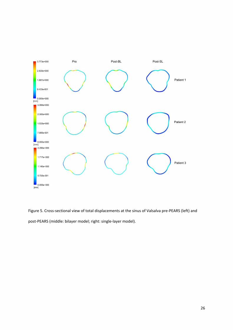
Upon addition of the external support and further integration into the aortic wall, the total
displacement of the aortic wall was significantly reduced, particularly in the aortic root and
sinuses of Valsalva. Figure 4 shows the maximum total displacement in the sinuses, and its
comparison with the displacement in the aortic arch, for each patient in every model. The
post-PEARS bilayer model is seen to have reduced displacements, both in the sinuses and the
aortic arch, when compared to the pre-PEARS models. Cross-sectional views of total

9
displacements in the sinuses of Valsalva are presented in Figure 5, which clearly illustrates
the reduction in displacement upon addition of the PEARS via the bilayer and single-layer
models. In the pre-PEARS and post-PEARS bilayer models, the maximum displacements
were located between the sinuses of Valsalva for Patients 1 and 2. In Patient 3, however, the
maximum displacement was found on the aortic arch. In contrast, the maximum
displacements obtained from the post-PEARS single-layer models were all located distal to
the aortic arch, that is, the location of the maximum displacement shifted from the sinuses to
unsupported regions in and around the aortic arch.
3.3 Stress distribution
In the pre-PEARS geometries, the ascending aorta and aortic arch generally had higher von
Mises stresses than regions distal to the aortic arch, with the peak stresses located between
the sinuses of Valsalva, as seen in Figure 6. In the post-PEARS bilayer models, which
simulate the biomechanical conditions immediately after insertion of the PEARS, similar
patterns were observed with the peak stresses also being located between the sinus for
Patients 1 and 2, but at the interface between the supported and unsupported region for
Patient 3.
The magnitude of the peak stress was significantly larger in the post-PEARS bilayer model
for Patients 1 and 2 but almost the same in Patient 3, as illustrated in Figure 7. In contrast,
the single-layer model had significantly reduced stresses in the sinus of all models while the
peak stresses were located at the interface between the supported and unsupported aorta.
Figure 8 illustrates regions of stress greater than 290 kPa in the post-PEARS single-layer
models for all three patients. Previous studies showed that peak stresses of an aneurysmal

10
aorta were between 290 and 450 kPa [26]. As a conservative comparison to a known
reference value, 290 kPa was chosen to highlight the high stress regions.
4. Discussion
Upon reconstruction, small differences in the shape and orientation of the aorta were
observed. In the post-PEARS images, discrimination of the aortic wall from the PEARS was
difficult, if not impossible, due to integration of the PEARS into the wall. The main purpose
of the PEARS is to provide an additional support for an otherwise weakened structure prone
to progressive dilatation and eventually dissection. In this manner, the PEARS allows the
aorta to expand and recoil without the risk of dilatation. The PTFE mesh used to manufacture
the PEARS is approximately 2.6 times stiffer than the Marfan aortic wall [24, 25]. The
material itself is less stiff than the material generally used (Haemashield, Dacron) to perform
the Bentall or valve-sparing root replacements. The mesh used in the PEARS procedure is
designed so that the hoop strength of the sleeve is greatest at the aorto-ventricular junction
and gradually diminishes towards the aortic arch.
Based on the results obtained, the integration of the PEARS (post-PEARS single-layer
model) showed reductions in the wall displacement of 63%, 68% and 62% in Patients 1, 2
and 3 respectively, in regions in and around the sinuses of Valsalva. These regions are known
to exhibit progressive aortic dilatation and hence, maintaining the aortic diameters stable in
the sinuses is important. However, reduction of the displacement in these areas also
corresponded to the maximum displacement being shifted distally to the aortic arch, near the
intersection between the supported and unsupported aorta. The magnitude of the maximum
displacement was nevertheless significantly smaller than the maximum value observed before
implantation of the PEARS (in the sinus). However, a local analysis showed that the aortic

11
arch was now subjected to increased displacements of 44% and 3% in Patients 1 and 2 and a
reduced displacement of 28% in Patient 3.
One of the concerns about the implantation of the PEARS is the formation of high stress
regions at the unsupported portion of the aorta, a limitation shared with the aortic root
replacement procedure. This study is the first attempt to address and quantify these concerns.
From the stress analysis, peak stresses in the pre-PEARS models were located in the sinuses
of Valsalva. The addition of the PEARS had an immediate effect on this peak stress which
was not only increased significantly (in Patients 1 and 2), but also remained within the
sinuses. Previous multilayer studies of stress distributions across the aorta have shown that
the peak stress concentrates itself in the stiffest layers [27]. Upon integration of the PEARS
into the aortic wall, stresses in the sinuses had reduced, while the peak stress was shifted to
the aortic arch, particularly at the intersection between the supported and unsupported aorta,
with corresponding increases of 183%, 156% and 89% for Patients 1, 2 and 3 respectively.
This highly focal increase in the wall stress could lead to further weakening of the wall at
these locations. Nevertheless, the peak stresses found in all the models presented here were
well below the tensile strength for dilated ascending aortas, which was reported to be
1.18±0.12 MPa in the circumferential direction and 1.21±0.09 MPa in the longitudinal
direction [28]. Another possible consequence of the focal increase in stress at these regions is
aortic remodelling [29]. The ability of the aorta to remodel itself under applied loads and
stresses can result in variation in wall thickness along the aorta.
5. Limitations
There are several limitations associated with the models developed in this study. One of the
most important simplifications in these analyses is the constitutive equation, which describes

12
the structural behaviour of the aortic wall. The aorta is multi-layered, heterogeneous and
anisotropic, and upon loading, it undergoes large deformation and stiffening under increased
pressures. Mechanical testing of samples of excised aortic tissue, healthy and diseased, has
enabled the development of various types of non-linear constitutive relations [30, 31].
However, data on the mechanical properties of the Marfan aorta are limited. The incremental
elastic moduli and distensibility have been measured in vivo and the Marfan aorta is found to
be significantly stiffer than normal aorta [17, 19]. Alternatively, studies by Okamoto et al.
[22, 23] and Auricchio et al. [15] have focused on dilated ascending aorta, using hyperelastic
constitutive formulations to describe the properties of the aorta. However, although these data
are available for dilated aortas, no information is available on the supported (sleeved) Marfan
aorta. Therefore, for comparative reasons, the linear-elastic constitutive formulation was
employed in this study, pending acquisition of more realistic data supported by experimental
studies.
The implications of using a simplified constitutive model were investigated by comparing
results obtained with the linear elastic model and a hyperelastic two-parameter Mooney-
Rivlin model. The pre-PEARS geometry of Patient 1 was used in this analysis. Qualitatively,
the stress and strain distributions were similar. The patterns revealed that the high stress and
strain regions were located at the sinus of Valsalva and the aortic arch in both models.
Quantitatively, there were differences between the two models: the maximum stress in the
sinus was 7% higher with the hyperelastic model while the strain at the same location was
62% lower. Despite these quantitative differences, the pre- and post-PEARS models in the
current study were developed using identical conditions, with differences in only the
geometry (patient-specific) and material properties. Therefore, comparison between the

13
models is still valid, which provides an estimate of the relative differences that could be
expected in vivo as a result of the insertion of the PEARS.
Also, the aortic wall thickness was assumed constant throughout the aorta due to insufficient
spatial resolution of the MRI protocol adopted for in vivo scans, which were acquired in a
clinical context. This is a common assumption adopted by several authors and its influence
on predicted wall stress has been addressed by others [32, 33]. The boundary between the
aortic wall and lumen were crudely visible in some MR images, from which rough estimates
of the thickness were obtained. However, lack of contrast between the aortic wall and lumen
in most images made measurement of the wall thickness along the length of the aorta
impossible.
In this study, the applied load corresponded to the patient’s pulse pressure rather than the
actual pressure, where increases in stress were taken as incremental changes from the
diastolic state. In reality, a zero-stress state does not exist in vivo, however, it was found that
the magnitude of residual stresses were negligible (up to 3 kPa [34]) in comparison with the
aortic root stresses observed at the peak pressure. However, it must be acknowledged that
residual stresses and strains act in homogenising the stress field in the arterial wall and allows
greater compliance [35].
Additional limitations to the current model arise from the boundary conditions employed, one
of which is the application of a uniform static load which corresponds to the patients’ pulse
pressure. However, in reality, this pressure will vary both spatially and temporally. Borghi et
al. [33] found very small differences (0.1% – 3.4%) in the predicted peak wall stress
resulting from fluid-structure interaction simulations (which employ a time-dependent

14
pressure waveform) and static structural analysis. Another boundary condition imposed on
the aortic model was the constraining of the aortic root to zero-displacement to simulate the
tethering to the rest of the aorta. Although this is a common assumption adopted by other
researchers [15, 35, 36] , in reality the ventricular contraction accompanying every heartbeat
results in the motion of the aortic root, which may in turn have a direct influence on the
deformation of the ascending aorta and the stress exerted on the aortic wall [37]. Future
improvements to the model will involve extracting patient-specific aortic root motion from
MR images and applying it as a more realistic boundary condition.
6. Conclusion
This study provides a preliminary biomechanical analysis of the Marfans’ aorta of three
patients having undergone implantation of the PEARS using combined imaging and
computational modelling. Finite element simulations were performed using patient-specific
geometries and pressures (pre- and post-PEARS). The stress and displacement distributions
were investigated to evaluate the effects of the external support on the biomechanics of the
aorta. The results showed that while the support reduced the displacement and stress
distributions in the aortic root, particularly in the sinuses of Valsalva, stresses at the
intersection between the supported and unsupported aorta were increased. Further studies are
required to assess the statistical significance and clinical relevance of these findings.

15
Acknowledgments
The author is grateful to Mr Tal Golesworthy (Extent Ltd, Tewkesbury, UK) for providing
material data of PEARS and CAD models used to produce the PEARS. Shelly Singh is
supported by a PhD scholarship from the Government of the Republic of Trinidad and
Tobago.

16
References
[1] Judge DP, Dietz HC. Marfan's syndrome. The Lancet. 2005;366:1965-76.
[2] Silverman DI, Gray J, Roman MJ, Bridges A, Burton K, Boxer M, et al. Family history of severe
cardiovascular disease in Marfan syndrome is associated with increased aortic diameter and
decreased survival. Journal of the American College of Cardiology. 1995;26:1062-7.
[3] Ramirez F, Dietz HC. Marfan syndrome: from molecular pathogenesis to clinical treatment.
Current opinion in genetics & development. 2007;17:252-8.
[4] Keane MG, Pyeritz RE. Medical management of Marfan syndrome. Circulation. 2008;117:2802-
13.
[5] Dormand H, Mohiaddin RH. Cardiovascular magnetic resonance in Marfan syndrome. Journal of
cardiovascular magnetic resonance : official journal of the Society for Cardiovascular Magnetic
Resonance. 2013;15:33.
[6] Hiratzka LF, Bakris GL, Beckman JA, Bersin RM, Carr VF, Casey DE, Jr., et al. 2010
ACCF/AHA/AATS/ACR/ASA/SCA/SCAI/SIR/STS/SVM guidelines for the diagnosis and management of
patients with Thoracic Aortic Disease: a report of the American College of Cardiology
Foundation/American Heart Association Task Force on Practice Guidelines, American Association for
Thoracic Surgery, American College of Radiology, American Stroke Association, Society of
Cardiovascular Anesthesiologists, Society for Cardiovascular Angiography and Interventions, Society
of Interventional Radiology, Society of Thoracic Surgeons, and Society for Vascular Medicine.
Circulation. 2010;121:e266-369.
[7] Bentall H, De Bono A. A technique for complete replacement of the ascending aorta. Thorax.
1968;23:338-9.
[8] David TE, Feindel CM, Bos J. Repair of the aortic valve in patients with aortic insufficiency and
aortic root aneurysm. The Journal of thoracic and cardiovascular surgery. 1995;109:345-52.
[9] Milewicz DM, Dietz HC, Miller DC. Treatment of Aortic Disease in Patients With Marfan
Syndrome. Circulation. 2005;111:e150-e7.
17
[10] Treasure T, Pepper J, Golesworthy T, Mohiaddin R, Anderson RH. External aortic root support:
NICE guidance. Heart. 2011;98:65-8.
[11] Pepper J, Golesworthy T, Utley M, Chan J, Ganeshalingam S, Lamperth M, et al. Manufacturing
and placing a bespoke support for the Marfan aortic root: description of the method and technical
results and status at one year for the first ten patients. Interactive cardiovascular and thoracic
surgery. 2010;10:360-5.
[12] Pepper J, John Chan K, Gavino J, Golesworthy T, Mohiaddin R, Treasure T. External aortic root
support for Marfan syndrome: early clinical results in the first 20 recipients with a bespoke implant.
Journal of the Royal Society of Medicine. 2010;103:370-5.
[13] Treasure T, Pepper JR. Aortic root surgery in Marfan syndrome. Heart. 2011;97:951-2.
[14] Verbrugghe P, Verbeken E, Pepper J, Treasure T, Meyns B, Meuris B, et al. External aortic root
support: a histological and mechanical study in sheep. Interactive cardiovascular and thoracic
surgery. 2013;17:334-9.
[15] Auricchio F, Conti M, Demertzis S, Morganti S. Finite element analysis of aortic root dilation: a
new procedure to reproduce pathology based on experimental data. Comput Method Biomec.
2011;14:875-82.
[16] Grande-Allen KJ, Cochran RP, Reinhall PG, Kunzelman KS. Mechanisms of aortic valve
incompetence: finite-element modeling of Marfan syndrome. The Journal of thoracic and
cardiovascular surgery. 2001;122:946-54.
[17] Vitarelli A. Aortic Wall Mechanics in the Marfan Syndrome Assessed by Transesophageal Tissue
Doppler Echocardiography. The American Journal of Cardiology. 2006;97:571-7.
[18] Baumgartner D, Baumgartner C, Matyas G, Steinmann B, Loffler-Ragg J, Schermer E, et al.
Diagnostic power of aortic elastic properties in young patients with Marfan syndrome. The Journal of
thoracic and cardiovascular surgery. 2005;129:730-9.
[19] Sonesson B, Hansen F, Lanne T. Abnormal Mechanical-Properties of the Aorta in Marfans-
Syndrome. Eur J Vascular Surg. 1994;8:595-601.

18
[20] Hirata K, Triposkiadis F, Sparks E, Bowen J, Wooley CF, Boudoulas H. The Marfan syndrome:
abnormal aortic elastic properties. Journal of the American College of Cardiology. 1991;18:57-63.
[21] Jeremy RW, Huang H, Hwa J, McCarron H, Hughes CF, Richards JG. Relation between age,
arterial distensibility, and aortic dilatation in the Marfan syndrome. Am J Cardiol. 1994;74:369-73.
[22] Okamoto RJ, Wagenseil JE, DeLong WR, Peterson SJ, Kouchoukos NT, Sundt TM. Mechanical
properties of dilated human ascending aorta. Annals of Biomedical Engineering. 2002;30:624-35.
[23] Okamoto RJ, Xu H, Kouchoukos NT, Moon MR, Sundt TM, 3rd. The influence of mechanical
properties on wall stress and distensibility of the dilated ascending aorta. The Journal of thoracic and
cardiovascular surgery. 2003;126:842-50.
[24] Nathan DP, Xu C, Plappert T, Desjardins B, Gorman JH, 3rd, Bavaria JE, et al. Increased ascending
aortic wall stress in patients with bicuspid aortic valves. Ann Thorac Surg. 2011;92:1384-9.
[25] Weltert L, De Paulis R, Scaffa R, Maselli D, Bellisario A, D'Alessandro S. Re-creation of a sinuslike
graft expansion in Bentall procedure reduces stress at the coronary button anastomoses: A finite
element study. The Journal of thoracic and cardiovascular surgery. 2009;137:1082-7.
[26] Vorp DA, Vande Geest JP. Biomechanical Determinants of Abdominal Aortic Aneurysm Rupture.
Arteriosclerosis, Thrombosis, and Vascular Biology. 2005;25:1558-66.
[27] Gao F, Watanabe M, Matsuzawa T. Stress analysis in a layered aortic arch model under pulsatile
blood flow. Biomedical engineering online. 2006;5:25.
[28] Torii R, Xu XY, El-Hamamsy I, Mohiaddin R, Yacoub MH. Computational biomechanics of the
aortic root. Aswan Heart Centre Science & Practice Series. 2011;16.
[29] Rachev A. Remodelling of Arteries in Response to Changes in their Mechanical Environment. In:
Holzapfel G, Ogden R, editors. CISM Courses and Lectures No 441 International Centre for
Mechanical Sciences: Biomechanics of Soft Tissue in Cardiovascular Systems. New York: Springer-
Verlag Wien 2003.
[30] Holzapfel G, Gasser T, Ogden R. A New Constitutive Framework for Arterial Wall Mechanics and
a Comparative Study of Material Models. Journal of elasticity. 2000;61:1-48.

19
[31] Gasser TC, Ogden RW, Holzapfel GA. Hyperelastic modelling of arterial layers with distributed
collagen fibre orientations. Journal of The Royal Society Interface. 2006;3:15-35.
[32] Scotti CM, Shkolnik AD, Muluk SC, Finol EA. Fluid-structure interaction in abdominal aortic
aneurysms: effects of asymmetry and wall thickness. Biomed Eng Online. 2005;4:64.
[33] Borghi A, Wood NB, Mohiaddin RH, Xu XY. Fluid-solid interaction simulation of flow and stress
pattern in thoracoabdominal aneurysms: A patient-specific study. J Fluid Struct. 2008;24:270-80.
[34] Raghavan ML. Three-Dimensional Finite Element Analysis of Residual Stress in Arteries. Annals
of Biomedical Engineering. 2004;32:257-63.
[35] Conti CA, Votta E, Della Corte A, Del Viscovo L, Bancone C, Cotrufo M, et al. Dynamic finite
element analysis of the aortic root from MRI-derived parameters. Med Eng Phys. 2010;32:212-21.
[36] Grande-Allen KJ, Cochran RP, Reinhall PG, Kunzelman KS. Finite-element analysis of aortic valve-
sparing: Influence of graft shape and stiffness. Ieee T Bio-Med Eng. 2001;48:647-59.
[37] Beller CJ, Labrosse MR, Thubrikar MJ, Robicsek F. Role of Aortic Root Motion in the
Pathogenesis of Aortic Dissection. Circulation. 2004;109:763-9.

20
Table 1. MR Scan parameters of images used for reconstruction
Repetition
time (ms)
Echo
time
(ms)
Flip
angle
(°)
Pixel
size
(mm)
Slice
thickness
(mm)
Interslice
distance
(mm)
Image
frequency
(MHz)
Patient 1 Pre 292.10 1.22 80 1.328 6.0 3 63.67
Post 296.38 1.07 70 0.594 1.5 var. 63.67
Patient 2 Pre 221.00 1.40 90 0.781 0.8 0.8 63.68
Post 251.00 1.45 70 0.625 2.0 2.0 63.68
Patient 3 Pre 338.87 1.22 80 1.328 6.0 3.0 63.68
Post 292.10 1.22 80 1.328 6.0 3.0 63.68

21
Table 2. Material properties used in the finite element models
Marfan wall PEARS Composite
Elastic modulus (kPa) 3000
7800
6750
Poisson’s ratio 0.49 0.35 0.45
Wall thickness (mm) 1.0
0.3 1.5
References [24] [25] [14]
Table 3. Patient data used in this study
Patient 1 Patient 2 Patient 3
Pre Post Pre Post Pre Post
Blood Pressure (mmHg)
Systolic 135 130 110 110 118 110
Diastolic 78 70 60 60 84 70
Pulse 57 60 50 50 34 40
Aortic root diameter (mm) 37.0 38.7 39.4 39.7 39.3 39.2
Ascending aorta (mm) 22.7 22.9 29.3 27.0 29.0 27.0
22
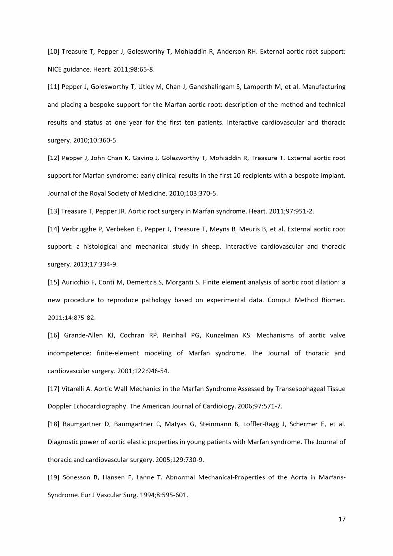
Figure 1. (a) Aortic model wrapped in the personalised external aortic root support (PEARS) which is
manufactured from a medical grade mesh; (b) Magnetic resonance imaging of the aorta before (left)
and after (right) insertion of the PEARS in the first patient.

23
Figure 2. Reconstructed patient-specific aortic geometries (a) pre-PEARS (b) post-PEARS,
immediately after implantation of the PEARS (bi-layer model) and (c) post-PEARS, when the PEARS
have become integrated into the periadvential tissue.

24
Figure 3. Pre-PEARS (left) and post-PEARS (right) luminal surfaces reconstructed from patient-
specific magnetic resonance imaging (MRI) for (a) Patient 1, (b) Patient 2 and (c) Patient 3,
respectively.
.

25
(a)
(b)
Figure 4. Maximum total displacement in the sinus of Valsalva (a) and aortic arch (b) obtained from
the Pre-PEARS, Post-PEARS (bilayer) and Post-PEARS (single-layer) models for Patients 1, 2
and 3.
26
Figure 5. Cross-sectional view of total displacements at the sinus of Valsalva pre-PEARS (left) and
post-PEARS (middle: bilayer model; right: single-layer model).

27
Figure 6. Stress distribution in Patients 1, 2 and 3 (from L-R: pre-PEARS, post-PEARS bilayer and post-
PEARS single-layer)

28
(a)
(b)
Figure 7. Maximum von Mises stress in the sinus of Valsalva (a) and aortic arch (b) obtained from the
Pre-PEARS, Post-PEARS (bilayer) and Post-PEARS (single-layer) models for Patients 1, 2 and 3.

29
Figure 8. Regions of stress greater than 290 kPa in the post-PEARS (single-layer) models for Patients
1, 2 and 3