Embed Size (px)
Citation preview

Biomechanics of Walking and Stair Ascent and Descent
D. Gordon E. Robertson, Ph.D.
Biomechanics, Laboratory,
School of Human Kinetics,
University of Ottawa, Ottawa, CANADA

Quantitative Domains
• Temporal–Phases (stance/swing) and events
(foot-strike, toe-off), stride rate
• Kinematic (motion description)– stride length, velocity, ranges of
motion, acceleration
• Kinetic (causes of motion)– ground reaction forces, joint forces,
moments of force, work, energy and power

Temporal Analysis
• Stride time
• Stride rate = 1/rate
• Stride cadence = 120 x rate (b/min)
• Instrumentation–Photocells and timers
–Videography (1 frame = 1/30 second)
–Metronome

Motion Analysis Tools
EMG
Force platform
Cine or Video camera

Electromyography
Delsys system
Mega system
Noraxon system Bortec system

Kinematic Analysis
• Study of motion without consideration of its causes
• Motion description
• Based on Calculus developed by Newton and Leibnitz
Isaac Newton, 1642-1727

Kinematic Analysis
• Linear position– Ruler, tape measure, optical
• Angular position– Protractor, inclinometer,
goniometer
• Linear acceleration– Accelerometry, videography
• Angular acceleration– Videography
Miniature accelerometers
Manual goniometer
Motion Analysis
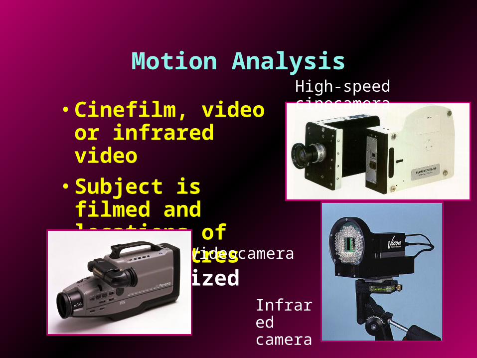
• Cinefilm, video or infrared video
• Subject is filmed and locations of joint centres are digitized
High-speed cinecamera
Videocamera
Infrared camera

Computerized Digitizing (APAS)

Computerized Digitizing (Simi)

Stick Figure Animation
Walking

Kinetic Analysis
Causes of motion
• Forces and moments of force
• Work, energy and power
• Impulse and momentum
• Inverse Dynamics derives forces and moments from kinematics and body segment parameters (mass, centre of gravity, and moment of inertia)

Force Platforms
2 Kistler force platforms
Ground reaction force

Steps for Inverse Dynamics
• Space diagram of the lower extremity

Divide Body into Segments and Make Free-Body Diagrams
• Make free-body diagrams of each segment

Add all Known Forces to FBD
• Weight (W)
• Ground reaction force (Fg)

Apply Newton’s Laws of Motion to Terminal Segment
• Start analysis with terminal segment(s), e.g., foot or hand
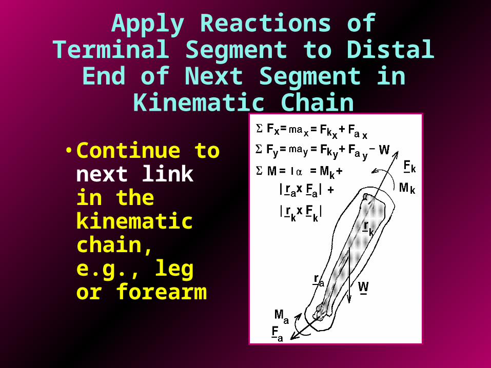
Apply Reactions of Terminal Segment to Distal End of Next Segment in Kinematic Chain
• Continue to next link in the kinematic chain, e.g., leg or forearm

Repeat with Next segment in Chain or Begin with Another Limb
• Repeat until all segments have been considered, e.g., thigh or arm

Joint Power Analysis
0.0 0.1 0.2 0.3 0.4Time (s)
-4000.
-2000.
0.
2000.
-300.
0.
300.
-20.
0.
20.
Pow
er
(W)
Mom
en
t (N
.m)
A
ng
ula
r vel.
(/s
)
SR11BJ
ITO CFS CTO IFS
Extending
Flexing
Extensor
Flexor
Concentric
Eccentric
• compute the net moment of force at the joint
• multiply angular velocity and moment of force to obtain the “moment power”
• this is the power produced by the net moment of force acting across the joint
• it is mainly caused by muscle forces
• compute the angular velocity of the joint

Normal Walking Example
• Female subject
• Laboratory walkway
• Speed was 1.77 m/s
• IFS = ipsilateral foot-strike
• ITO = ipsilateral toe-off
• CFS = contralateral foot-strike
• CTO = contralateral toe-off

Ankle angular velocity, moment of force and power
• Dorsiflexors produce dorsiflexion during swing
• Plantar flexors control dorsiflexion
• Large burst of power by plantar flexors for push-off 0.0 0.2 0.4 0.6 0.8 1.0 1.2
Time (s)
-200
-100
0
100
-100
0
100
-10
0
10
P
ow
er
(W)
Mo
me
nt
(N.m
)
A
ng
. V
el.
(ra
d/s
)
Trial: 2SFN3Ang. velocityMomentPower
CFS ITO IFS CTO CFS ITO
Dorsiflexion
Plantar flexion
Dorsiflexors
Plantar flexors
Concentric
Eccentric

Knee angular velocity, moment of force and power
• Negative work by extensors to control flexion at push-off
• Burst of power to cushion landing
• Negative work by flexors to control extension prior to foot-strike
0.0 0.2 0.4 0.6 0.8 1.0 1.2Time (s)
-200
-100
0
100
-100
0
100
-10
0
10
P
ow
er
(W)
M
om
en
t (N
.m)
A
ng
. V
el.
(ra
d/s
)
Trial: 2SFN3Ang. velocityMomentPower
CFS ITO IFS CTO CFS ITO
Extension
Flexion
Extensors
Flexors
Concentric
Eccentric

Hip angular velocity, moment of force and power
0.0 0.2 0.4 0.6 0.8 1.0 1.2Time (s)
-200
-100
0
100
-100
0
100
-10
0
10
P
ow
er
(W)
Mo
me
nt
(N.m
)
A
ng
. V
el.
(ra
d/s
)
Trial: 2SFN3Ang. velocityMomentPower
CFS ITO IFS CTO CFS ITO
Flexion
Extension
Flexors
Extensors
Concentric
Eccentric
• Positive work by flexors to swing leg
• Positive work by extensors to extend thigh
• Negative work by flexors to control extension

Solid-Ankle, Cushioned Heel (SACH) Prostheses

Stick Figure Animation
Walking with SACH foot

0.0 0.2 0.4 0.6 0.8 1.0 1.2 1.4
Time (s)
-200.
-100.
0.
100.
-100.
0.
100.
-10.
0.
10.
Po
we
r (W
)
Mo
me
nt
(N.m
)
An
gu
lar
ve
l. (
/s)
Ankle angular velocity, moment of force and power of SACH foot prosthesis
• No power produced during push-off
Trial: WB24MH-SAng. velocityNet momentPower
ITO IFS CTO CFS ITO
Dorsiflexing
Plantar flexing
Dorsiflexor
Plantar flexor
Concentric
Eccentric
• Power dissipation during weight acceptance and push-off

FlexFoot Prostheses(Energy Storing)
Recent models
Original model

Stick Figure Animation
Walking with FlexFoot prosthesis

Ankle angular velocity, moment of force and power of FlexFoot prosthesis
• Power returned during push-off
0.0 0.2 0.4 0.6 0.8 1.0 1.2
Time (s)
-500.
-250.
0.
250.
-100.
0.
100.
-10.
0.
10.
Po
we
r (W
)
M
om
en
t (N
.m)
A
ng
ula
r v
el.
(/s
)
Trial: WB13MH-FAng. velocityNet momentPower
ITO IFS CTO CFS ITO
Dorsiflexing
Plantar flexing
Dorsiflexor
Plantar flexor
Concentric
Eccentric

Ankle angular velocity, moment of force and power of person with hemiplegia (stroke side)
• No power during push-off
0.0 0.2 0.4 0.6 0.8
Time (s)
-2000.
-1000.
0.
1000.
-200.
0.
200.
-15.
0.
15.
Po
we
r (W
)
M
om
en
t (N
.m)
A
ng
ula
r ve
l. (
/s)
Trial: WPP14EGAng. vel.Net momentPower
IFS CTO CFS ITO IFS
Dorsiflexing
Plantar flexing
Dorsiflexor
Plantar flexor
Concentric
Eccentric

Ankle angular velocity, moment of force and power of person with hemiplegia (normal side)
• Power at push-off is reduced due to slower gait
0.0 0.2 0.4 0.6 0.8
Time (s)
-2000.
-1000.
0.
1000.
-200.
0.
200.
-15.
0.
15.
P
ow
er
(W)
Mo
me
nt
(N.m
)
An
gu
lar
ve
l. (
/s)
Trial: WPN03EGAng. vel.Net momentPower
IFS CTO CFS ITO IFS
Dorsiflexing
Plantar flexing
Dorsiflexor
Plantar flexor
Concentric
Eccentric
• Negative power is also reduced

Other Gait Patterns
Above-knee Prostheses

Stick Figure Animation
Walking with Terry Fox prosthesis

Support Moment
• Used to quantify stability during stance of gait
• Sum of ankle, knee and hip moments
• Extensors moments are made positive
Msupport = Mankle + Mknee + Mhip
• Should remain positive throughout stance despite loss of function at one or more joints
• Studies have shown that even people with artificial joints produce a positive support moment throughout stance
(Winter, J. Biomech, 13, 923-927, 1980)

Support Moment during Walking
• Support moment is positive throughout stance
• Typically has two peaks one after IFS and one before ITO
0.0 0.2 0.4 0.6 0.8 1.0 1.2Time (seconds)
-200.
-100.
0.
100.
-100.
0.
100.
-100.
0.
100.
-100.
0.
100.
200.
Net
mo
men
ts o
f fo
rce
(N.m
)
Trial: CJWK
IFS CTO CFS ITO
Support moment
Hip extensor
Knee extensor
Ankle extensor• Ankle plantar
flexors are the most important from midstance to toe-off

Laboratory Stairs
• Step height = 24 cm
• Step tread = 30 cm
• Railings = 36 in.
• Height and tread are adjustable
Force platformsForce platforms

Stick Figure Animation
Up One Step from Landing

Up One Step from Landing
• Smaller ankle plantar flexor moment
• Larger than normal knee extensor moment
0.7 0.9 1.1 1.3 1.5 1.7 1.9 2.1 2.3Time (seconds)
-200.
-100.
0.
100.
-100.
0.
100.
-100.
0.
100.
-100.
0.
100.
200.
Net
mo
men
ts o
f fo
rce
(N.m
)
Trial: STLUP7RH
ITO IFS ITO
Support moment
Hip extensor
Knee extensor
Ankle extensor
• Support moment similar to walking

Similarities to Walking
• Double support periods
• Ground reaction forces have double peak
• Cadence similar
• Support moment is similar (always positive with two peaks)
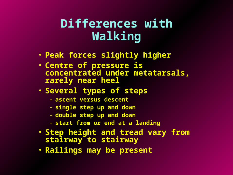
Differences with Walking
• Peak forces slightly higher• Centre of pressure is concentrated under
metatarsals, rarely near heel• Several types of steps
– ascent versus descent– single step up and down– double step up and down– start from or end at a landing
• Step height and tread vary from stairway to stairway
• Railings may be present

Ascent versus Descent
• Descent is more dangerous because if tripping occurs person will fall farther
• Descent is more likely to cause fall since centre of pressure and centre of gravity is closer to edge of stair

Factors Influencing Stability
• Weight
• Size of base of support (hand rails)
• Friction
• Distance from tipping edge
• Height of centre of gravity
• Visual field
• Vestibular system
• Inebriation/drugs
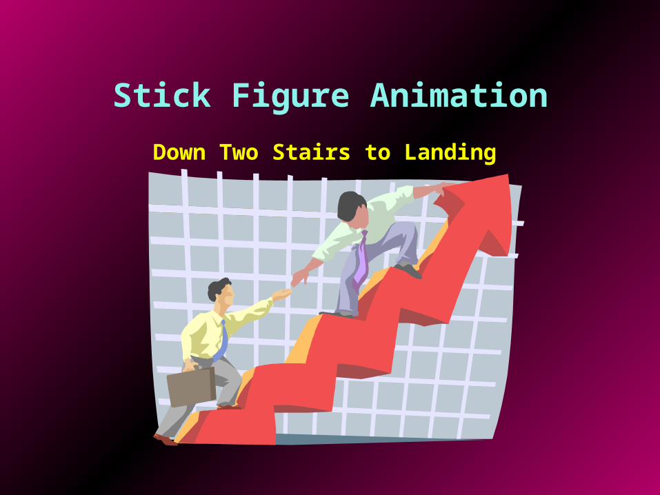
Stick Figure Animation
Down Two Stairs to Landing

Down Two Stairs Forwards
• Larger than normal negative power by ankle plantar flexors after foot-strike (IFS)
0.7 0.9 1.1 1.3 1.5 1.7 1.9 2.1Time (seconds)
-500.
-250.
0.
250.
500.
-250.
0.
250.
-250.
0.
250.
500.
Po
wer
(w
atts
)
Trial: CJRFD
ITO IFS ITO
Hip powers
Knee powers
Ankle powers
• Positive work done after IFS by knee flexors

Possibly Safer Descent
• Descend backwards
• Centre of pressure and centre of gravity are farther from edge of stairs
• If tripping occurs person falls into stairs not down stairs
• Person will be “forced” to use railing
• Problem with seeing next step
• Some people may have problem with neck

Stick Figure Animation
Down Two Steps Backwards

Down Two Stairs Backwards
• No concentric knee power required after IFS
0.5 0.7 0.9 1.1 1.3 1.5 1.7 1.9 2.1Time (seconds)
-500.
-250.
0.
250.
500.
-250.
0.
250.
-250.
0.
250.
500.
Po
wer
(w
atts
)
Trial: CJLBD
ITO IFS ITO
Hip powers
Knee powers
Ankle powers
• Larger than normal negative power by ankle plantar flexors after foot-strike (IFS)
• No push-off power needed from ankle

What’s Next
• Modify rise and tread• At-risk subjects
– Elderly– Infants– Disabled– Distracted– Prostheses– Robots
• Ramps versus stairs– Angle of ramp– Surface friction
• Cambered surfaces

Questions?
Answers?
Comments?