Embed Size (px)
Citation preview

Turk J Elec Engin, VOL.16, NO.3 2008, c© TUBITAK
Biomedical Circuits and Systems Dedicated for
Sensing and Neurostimulation: Case study on Urinary
Bladder dysfunctions
Mohamad SAWAN1, Aguibou BA1, Faycal MOUNAIM1,Jacques CORCOS2, Mostafa ELHILALI2
1Polystim Neurotechnologies Laboratory, Department of Electrical Engineering,Ecole Polytechnique de Montreal, Canada 2900 Edouard Montpetit,
P.O.Box 6079, Station Centre-Ville, Montreal (QC), CANADA H3C 3A7e-mail: [email protected]
2Department of Urology, McGill University, CANADA
Abstract
This paper covers circuits and systems techniques for the construction of high reliability biosensing and
neurostimulation smart medical devices. Such microsystems are dedicated for interconnections through
the peripheral neural systems. Case study related to applications such as bladder control is discussed.
Available electrical neurostimulation techniques for the rehabilitation of urinary bladder functions do not
allow an adequate voiding due to dyssynergia between the bladder and the sphincter. A new implantable
stimulator, built with commercially available electronic components, was designed to overcome these
difficulties. The proposed system performs two types of stimulations: Selective Stimulation for bladder
voiding and Permanent Stimulation to reduce the bladder overactivity symptoms. Also, a fully integrated
extended version of the stimulator is achieved with the additional ability to monitor the electrodes-
nerve contact impedance variations in order to detect electrodes faults or nerve physiology changes. The
implemented full custom device provides a reliable stimulation technique and addresses the lack of features
(programmable parameters, user-friendly interface and waveform flexibility) of the previous stimulation
devices. Experimental results of the fabricated chip confirm its functionality. The microstimulator
generates a wide range of stimuli waveforms with variable parameters and its modular architecture makes
it an expandable multichannel stimulation system.
Key Words: Medical device, Electronic implant, Electrical stimulation, Selective stimulation, Bladder
controller, Detrusor-sphincter dyssynergia, Neurogenic detrusor overactivity, Hyper-reflexia.
1. Introduction
Innovative circuits and systems techniques are required to build advanced smart medical devices (SMD).The high reliability and very low power consumption are among the main criteria that must be givenpriority to implement such implantable and wirelessly controlled microsystems. A typical SMD is composedof several integrated modules to be assembled on a thin substrate providing placement flexibility in thebody [1–3]. Data recording, monitoring of electrodes-tissues interface condition for enhanced safety, and
171

Turk J Elec Engin, VOL.16, NO.3, 2008
for enabling troubleshooting after implantation are needed. In addition, in order to improve controllabilityand observability, bidirectional full-duplex communication canal between external controllers and implantsis required. Regarding the spinal-cord injured patients at the T12 level or higher can lose the control oftheir urinary bladder. These patients become unable to voluntarily evacuate the urine from filled bladdersand often suffer from many complications such as the neurogenic detrusor overactivity (NDO) or detrusorhyperreflexia which is an overactivity of the autonomic nervous system. The overfull bladder sends sensitiveneural signals to the spinal cord where they travel upward until they are blocked by the lesion at the levelof injury. Since these sensitive neural signals cannot reach the brain, the reflex arc stays activated, increasesactivity of the sympathetic portion of the autonomic nervous system and causes spasms. In most cases,incontinence occurs due to NDO or dysfunctions of the bladder neck (urethral insufficiency) [4].
1.1. Electrical stimulation to recover the micturition function.
Several types of Functional Electrical Stimulation (FES) have been introduced in order to recover thevoluntary control of the micturition reflex at different sites of the urinary system. Four main stimulationsites have been investigated: the bladder muscle (detrusor), the pelvic nerves, the spinal cord and the sacral
roots [5–10].
The electrical stimulation of the detrusor did not induce an adequate voiding and the required highamplitude of the stimulation current may cause damages [11, 12]. FES has been applied to the pelvicnerves, but their relation with the pudendal nerves generated a simultaneous excitation of the sphincter andthe detrusor. This phenomenon, known as Detrusor Sphincter Dyssynergia (DSD), induces high detrusorpressure that may eventually lead to incontinence or kidney failure. An alternative solution implyingneurotomy of the pudendal nerve has been proposed but the surgical approach makes this technique lesspopular [10, 13].
The stimulation of the spinal cord has been performed, but using penetrating electrodes may causethe double activation of the bladder and the striated sphincter muscles [14], [15]. The last stimulation site,the sacral roots, is one of the most promising methods, but early conventional stimulation of sacral nervesinduces once again the DSD [11]. Recently, applying specific stimuli that allow overcoming the DSD attractedresearchers attention. In fact, the detrusor and the external sphincter muscles share the sacral nerves ascommon innervation pathways. The autonomic afferent roots stimulate the sacral micturition reflex, whilethe somatic efferent pathways (controlled by the brain) are responsible for the contraction of the external
sphincter [4]. This sacral roots stimulation method is the subject of the present work.
1.2. Sacral roots stimulation techniques
The intermittent stimulation of the sacral roots, also known as post-stimulus voiding, has been describedand largely used in patients [16]. By stimulating the sacral nerves adequately, contractions can be inducedin both the detrusor and the sphincter, but only the striated sphincter muscle is able to relax between thestimuli, thus allowing urine evacuation. The used stimulation pattern consists of intermittent pulse trains(typically, 3 to 6 seconds stimulation and 6 to 9 seconds stop). Good clinical results have been observed, butthis intermittent stimulation method is characterized by a high intravesical pressure and high level of urineresidue that are damageable for the kidneys. Also neurectomy of nerves may be required in most cases [17].
Another sacral nerve stimulation technique is the sphincteric fatigue. In this case, the pudendalnerves are stimulated with high-frequency signals until induction of the sphincteric fatigue. It is followed
172

SAWAN, BA, MOUNAIM, CORCOS, ELHILALI: Biomedical Circuits and Systems Dedicated for...,
by low frequency stimulation of the sacral nerves for voiding. This two-steps technique takes advantage ofthe difference between the contraction and the relaxation periods of the sphincter and the bladder. Even ifthis concept avoids neurectomy, it produces inefficient results comparable to those obtained with patientsfollowing pudendal neurectomy [18, 19].
More than a decade ago, a selective blockage method has been introduced. It is based on the blockagethreshold (or excitation) difference of the A-delta and A-alpha fibers. Multiple types of blockage techniques
have been tried: pudendal nerves collision [20], anodal block by sacral roots stimulation [21], [22], and
pudendal nerves high-frequency blockage [23, 24]. Recently, authors introduced the selective activationtechnique of the small nerves fibers in the sacral roots by combining a cathodic excitation of all fibers anda selective anodic blockage of the large fibers [25, 26]. This technique achieves hyperpolarization of thenerve membrane between the excitation application point and the external urethral sphincter to prevent thepropagation of nerve action potentials toward the sphincter. In fact, the large diameter fibers innervatingthe sphincter having a lower excitation threshold than those with small diameter; this blockage techniqueallows selective activation of the detrusor muscle thus inducing an efficient voiding. More recently, selectivedetrusor muscle activation has been obtained by performing stimulation of the sacral roots with a signalcomposed of two distinctive trains of bipolar-current pulses [27]. This stimulation technique is elaboratedlater in this paper.
1.3. Available implantable stimulators
Few implantable electronic devices were introduced for clinical purposes to address the bladder dysfunctions.Finetech presented in 1985 a triple transcutaneous stimulator generating monophasic stimuli [28]. In 1987,
Physico-Med introduced a monochannel stimulator for urinary retention [29]. In 1997, Medtronic introduceddevices for incontinence treatment and several versions followed. The Medtronic InterStim therapy is largelyused worldwide for both purposes, incontinence and retention [30]. More recently, the Vocare bladder systemintroduced by NeuroControl, which is an updated version of the Finetech stimulator, has been approved forthe North American market [31]. However, this device requires rhizotomies to achieve bladder voiding.
In the past years, several implantable stimulators and their external controllers have been proposedby our research team [32–34]. Multiple stimulation techniques were used for the rehabilitation of voluntarybladder voiding. Recently, we introduced an implantable device which is powered and controlled by a hand-held interface. The implant can deliver combined stimuli in order to selectively stimulate the bladder andthe sphincter [33] as well as a battery powered Permanent stimulation with a long lasting life. Prototypes,made with commercially available electronic components, have been realized and used to conduct chronicstudies on dogs during eight months. By means of selective stimulations using the high frequency blockage,DSD is reduced or even avoided. In addition, the Permanent stimulation demonstrated the feasibility toreduce the NDO [35]. These preliminary good results motivated us to improve our device and to addressthe lack of features such as a wide range of programmable parameters, a user-friendly interface, and thewaveform flexibility. In addition, we proceeded to build a fully integrated version of our stimulation system,to which we added new required features such as the electrode-nerve impedance monitoring.
The remainder of this paper focuses on a description of the FES system which will be given in sectionII. In section III, we present the new miniaturized system, while Section IV describes the experimentalresults. We discuss the obtained results in section V and conclude this work.
173

Turk J Elec Engin, VOL.16, NO.3, 2008
2. Selective and Permanent Neurostimulator
A first version of the Selective and Permanent Neurostimulation System, which was built around off-the-shelf electronic components, is composed of an external controller, an electronic implant, and a bipolar cuffelectrode to interface the implant with one of the sacral nerves.
2.1. The external controller
The external controller has three main features: 1) Power the implant by sending wireless inductive energy,
2) Select stimulation type (Permanent or Selective), and 3) Select the desired parameters (width, frequency
and amplitude). When a Selective stimulation is requested, the implant generates current pulses as longas the inductive link is maintained. For the Permanent low-frequency stimulation, it automatically runswhen the inductive link is interrupted. The external controller includes a user interface composed of fewpush buttons and a LCD. It is based on a finite state machine implemented in a commercially availablemicrocontroller (Figure 1). A power amplifier is used to transcutaneously transfer the needed energy usingan inductive coupling technique to power up the implant. Commands and data are Manchester encoded andsent to the implant with an Amplitude Shift Keying (ASK) modulation of a 20 MHz RF carrier.
����������
�� ��
����� �
�
���
��
�
���� ����� �
���������� �
���
���
���
��� ���� ����
������
���� �������
�������
������
���
���� ������ �� �� �� �
�������
� ��
�������������!��� ���
�����
�� �����������
!��� ��� �����
"#$%&%#���
�������'
( ����� �� )*
( ����� �� )�
�� ����()*
�� ����()�
Figure 1. Block diagram of the stimulation system.
2.2. The implant
The system allows two operation modes for the implant: Selective or Permanent stimuli generation. Eachmode is handled by an independent Stimuli Generator (SG). The block diagram of the implant, shown in
Figure 1, is composed of a data and power recovery block, two SG’s, two bipolar current sources (BCS) anda common switching stage to generate biphasic stimuli. The front-end block allows the demodulation of datasent by the external controller and the recovery of inductive energy to power up the selective stimulationblock. On the other hand, the Permanent Stimuli Generator (PSG) is entirely powered by an embedded
battery without any direct interaction with the external controller. The Selective Stimuli Generator (SSG),
built within a FPGA (Field Programmable Gate Array), contains an internal controller which is in charge
of data decoding and verification using a communication Cyclic Redundancy Check (CRC) technique.
174

SAWAN, BA, MOUNAIM, CORCOS, ELHILALI: Biomedical Circuits and Systems Dedicated for...,
Furthermore, it generates the adequate commands to produce selective stimulation waveforms or transfers tothe PSG the required Permanent stimulation parameters. This PSG is built within a commercially availablemicrocontroller. After reception and verification of the parameters, the PSG generates commands to producelow amplitude stimuli for the Permanent stimulation. Each SG controls its own BCS which contains a digitalto analog converter and an operational amplifier based current source to deliver constant current pulses.
The Selective stimulation technique duplexes high and low frequency (HF & LF) stimuli alternatelyto respectively activate somatic A-alpha fibers, which innervate the sphincter and parasympathetic A-deltafibers innervating the detrusor muscle. Figure 2a shows a typical waveform of this technique. The Permanentstimulation is composed of a train of low-frequency pulses (Figure 2b). Also, biphasic stimuli are applied toavoid accumulation of charges at the electrode-nerve interface.
+��
+��,��
+�-
,�- ,��
.�/
0�� 0���
*1� �2
���
�-
.3/
Figure 2. Stimulation waveforms: (a) Selective stimulation, (b) Permanent stimulation.
Selective stimulation may require high current amplitudes (up to 2 mA over a 1 kohm impedance). Inorder to avoid saturation of the current source with higher nerve impedance, a 5 V DC voltage is regulatedfrom the received inductive energy carried at a frequency of 20 MHz. Special attention has been paid toisolate the battery from the inductive link to avoid any current leakage and consequent battery lifetimedegradation. The dual SG architecture of the implant enrolls two independent stimulation pathways withindependent power supplies. We thus have an implant that can be either a high amplitude bi-frequencySelective stimulator or a low power and low amplitude continuous stimulator.
A prototype of this new microstimulator was built on a printed circuit board (PCB) with commercialintegrated circuits and discrete components. An Actel 40MX04 FPGA and a PIC16F84 Microchip micro-controller were used for the controllers. An 8-bit serial DAC (MAX550A) was selected to drive the currentsources. This DAC occupies less space than equivalent parallel DAC used in previous versions of the implant.The remaining integrated circuits were chosen within the Texas Instruments family of CMOS circuits. Theywere mainly selected for small size factor and low power consumption requirements. Also, the battery is
175

Turk J Elec Engin, VOL.16, NO.3, 2008
a coin type Lithium battery (500 mAh), which should keep the implant operational for more than a yearwith nominal parameters. The inductive link receiving coil is a concentric 3-turn spiral of copper conductorintegrated into the same PCB.
In-circuit programming function of the microcontroller is used to facilitate future updates of themicrocontroller’s code after final assembly of the implant. Connection jumpers were included in the PCBto connect a serial programmer. When assembled, the implant was placed in a test-bench which simulatesintensive use of the microstimulator in all operating modes. Afterwards, the whole circuit was protectedby a triple layer polyurethane coating. This coating is not adapted for medical applications and has to beperfectly dry and free from any solvent before being covered with a biocompatible material. The implantis again submitted to another test-bench in a bath of saline solution at +40 o C. Then it is coated with abiocompatible silicone. To ensure a uniform coating, the microstimulator is placed in a mould where liquidsilicone is injected and then is heated at 65 oC for 6 hours. Figure 3 shows a photograph of the resultingimplant.
Figure 3. Photograph of the implantable stimulator.
2.3. The cuff electrodes
The proposed design is a split-cylinder cuff electrode with shape memory alloy (SMA) armature embedded
inside the cuff wall (Figure 4). The electrode cuff is molded in a biocompatible silicone, and two electrodecontacts are cut from a platinum foil of 25 μm thickness. The leads of electrodes are multi-strands stainlesssteel wires coated with Teflon. For the SMA armature, medical grade NiTi (50.7% Nickel, 49.3% Titanium)wires of 0.1 mm of diameter are used. This structure provides new mechanical properties to the wholeelectrode’s cuff. It enables the electrode self-closing around the nerve during installation and its maintenancein place without requiring additional fixation means such as sutures. SMA electrodes are easy to wrap andto manipulate when kept at low temperature, but they automatically recover their original shape (cylindrical
around the nerve) when heated at body temperature [36].
By applying selective electrical stimulation, the somatic fibers driving the sphincter can be stimulatedwithout causing simultaneous contraction of the bladder; a high-amplitude, low frequency train provokesdetrusor muscle contraction while a low-amplitude, high-frequency train inhibits the external urethralsphincter contraction to allow micturition. This type of blockage maintains the nerves and their motor endsin a refractory state to impede the external sphincter from contracting. This stimulation method allowsbladder evacuation with a low-pressure voiding and low residual urine. It has been shown that the most
176
SAWAN, BA, MOUNAIM, CORCOS, ELHILALI: Biomedical Circuits and Systems Dedicated for...,
efficient blockage frequency was around 600 Hz [27]. Typical bladder (Pves) and urethra (Pura) pressures
as well as electromyography (EMG) activity responses are shown in Figures 5a and 5b.
0����4������4���4�� ��
���4� ��� �4�������'�4�������4���
�������4 33� 4���
(�������4����4��4������4���
Figure 4. The shape memory alloy-based nerve cuff electrode.
.�/
.3/
Figure 5. Typical CMG during: (a) Selective stimulation, (b) Permanent stimulation.
The dual stimulation technique has been validated by off-the-shelf electronic components built ina double face printed circuit board, but it does not allow monitoring of the electrode-tissues contact.Obtained results motivated us to build a fully integrated microstimulator on chip, together with the requiredmeasurement interface.
3. Fully Integrated On Chip Stimulator and Monitor
3.1. Overview of the device
The new fully integrated stimulator and monitor (ISAM) delivers both stimulation types: Selective andPermanent. It also allows generating flexible stimulation patterns, and characterizing the impedance of the
177
Turk J Elec Engin, VOL.16, NO.3, 2008
electrodes-nerve contact. Similar to the previous designed stimulator, the operation mode of the implantis selected by the external controller and the corresponding parameters are transmitted wirelessly. TheSelective stimulation mode and the measurement technique require much more energy than continuousstimulation. Thus they are powered by the external controller. Waveforms generated for all modes are fullyreprogrammable by the means of various parameters (amplitude, frequency, pulse widths, on and off times).
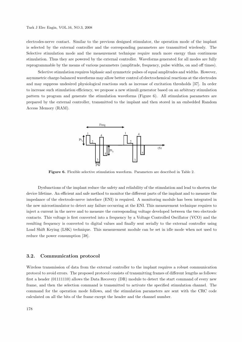
Selective stimulation requires biphasic and symmetric pulses of equal amplitudes and widths. However,asymmetric charge-balanced waveforms may allow better control of electrochemical reactions at the electrodesand may suppress undesired physiological reactions such as increase of excitation thresholds [37]. In orderto increase such stimulation efficiency, we propose a new stimuli generator based on an arbitrary stimulationpattern to program and generate the stimulation waveforms (Figure 6). All stimulation parameters areprepared by the external controller, transmitted to the implant and then stored in an embedded RandomAccess Memory (RAM).
� �2
��*
��"
�-
*
�
%
5
"
*
�
%
5
"
.�/
Figure 6. Flexible selective stimulation waveform. Parameters are described in Table 2.
Dysfunctions of the implant reduce the safety and reliability of the stimulation and lead to shorten thedevice lifetime. An efficient and safe method to monitor the different parts of the implant and to measure theimpedance of the electrode-nerve interface (ENI) is required. A monitoring module has been integrated inthe new microstimulator to detect any failure occurring at the ENI. This measurement technique requires toinject a current in the nerve and to measure the corresponding voltage developed between the two electrodecontacts. This voltage is first converted into a frequency by a Voltage Controlled Oscillator (VCO) and theresulting frequency is converted to digital values and finally sent serially to the external controller usingLoad Shift Keying (LSK) technique. This measurement module can be set in idle mode when not used to
reduce the power consumption [38].
3.2. Communication protocol
Wireless transmission of data from the external controller to the implant requires a robust communicationprotocol to avoid errors. The proposed protocol consists of transmitting frames of different lengths as follows:first a header (01111110) allows the Data Recovery (DR) module to detect the start command of every newframe, and then the selection command is transmitted to activate the specified stimulation channel. Thecommand for the operation mode follows, and the stimulation parameters are sent with the CRC codecalculated on all the bits of the frame except the header and the channel number.
178

SAWAN, BA, MOUNAIM, CORCOS, ELHILALI: Biomedical Circuits and Systems Dedicated for...,
3.3. Architecture of the implantable device
The integrated on chip ISAM is based on an expandable multichannel modular architecture (see Figure 7).This device includes four main blocks. The front-end block of the implant includes a Manchester decoderand a DR module. The Manchester decoder retrieves the binary digits received from the external controller.It recovers a 300 KHz global clock and transfers all remaining data to the DR module. The DR moduledetects the 8-bit header, identifies the channel and decodes the stimulation mode. This is followed by thetransfer of the stimulation parameters to the specified channel. After activation of the channel, the front-endblock remains in a wait state until the system is re-initialized.
��� (���� �� ���� �� ��
6�������� ���� �����
����'���� ������
��0���(7#��8
� ���$��� ���
('���������!��� ��� .(�! */
��3��������
('���������!��� ��� .(�! �/
��3��������
���������('����.�( */
���������('����.�( �/
**
9
**
9
"
(+:
(+:����7��
����
����';��
�� ��
����
Figure 7. Block diagram of the integrated microstimulator.
One of the characteristics of the communication protocol is to introduce stuffing zeros into the frameto avoid six consecutive 1’s other than those of the header. Thus, the system is stopped during a clock cyclefollowing the detection of five consecutive 1’s, but only after the detection of a valid header. A CRC block,based on a polynomial division technique, is used to guarantee the integrity of received parameters. If therest of the polynomial division is equal to zero, the CRC is valid.
After the recovery of the stimulation parameters by the front-end block, the Channel Stimuli Generator(CSG) produces the signals which control the generation of the programmed stimuli. Our system integrates
two Stimulation Channels (SC), which are connected to the front-end block by the same data bus and areactivated selectively by a signal coming from the DR block. Each stimulation channel includes a data registerto store the stimulation mode, the activation signal of the channel coming from the front-end block, and thenumber of points if flexible selective stimulation is used.
The RAM block in each CSG is divided into 32 eight-bit addresses to store all the stimulationparameters, and up to 30 points for the flexible stimulation. The writing operations are controlled bythe front-end block while the reading operations depend exclusively on a Finite State Machine (FSM) whichcontrols the CSG. After detecting the activation signal from the front-end block, the FSM gets the stimulationparameters from the RAM. The outputs are fed to a demultiplexer used as register and which sends theadequate stimulation parameters to the waveform generator block.
Following detection of the stimulation mode and storage of the parameters in the specified RAM, theStimuli Waveform Generator (SWG) starts delivering the stimuli. This SWG, shown in Figure 8, includesseveral building blocks such as frequency dividers, counters, comparators and a FSM. The stimulationparameters are summarized in Table 1. The selective stimulation is composed of two combined bipolar
179

Turk J Elec Engin, VOL.16, NO.3, 2008
waveforms. A High Frequency pulse Width (HFW) and High Frequency Amplitude (HFA) characterize the
first waveform. Each time the Low Frequency Period (LFP) is attained, a pulse is produced with a Low
Frequency Amplitude (LFA) and Low Frequency Width (LFW). The LFP and High Frequency Period (HFP)are generated by counters. For the permanent stimulation, bipolar low frequency waveform is producedduring the on time (Ton). A counter and a comparator are used for the frequency (FREQ) and the Pulse
Width (PW). The stimuli amplitude is directly fed to the SG and during the off-time (Toff), the module isdisabled.
Table 1. Stimulation parameters of the integrated microstimulator.
Type Command Parameters (bits)Permanent 10101010 LFP 8 LFW 8 AMP 8 Ton 4 Toff 4
Impedance measure 11001100 Freq 8 PW 8 AMP 8 Teval 4 Tsetup 4Selective 00001110 LFP 8 HFP 8 LFW 8 HFW 8 LFA 8 HFA 8Flexible 01110000 Nb pt 4 Freq 8 PW 8 Pt 1 8 Pt 2 8 Pt x 8
� �2����������
���!��� ���
(��� �����
0��0���
� �2���������� � �2����
������ ���
!��� ���
��-���'
!��� ���
��
�������� �
��<�
������
����
���
,�-
+�-
,��
+��
,��
+��
0��0���
(+:
���3�
Figure 8. Block diagram of the Stimuli Waveform Generator.
For the flexible selective stimulation, a block is dedicated to the creation of the stimulation pattern.This module receives the eight-bit amplitude, the pulse duration, the stimulation pattern frequency and anactivation signal, which indicates the beginning of stimulation.
When the desired pulse duration is reached, the generation of a new stimulation point is started.When all the points are produced, the block enters a waiting mode. The cycle restarts once the frequencypattern is reached.
A receiving signal allows the detection of RF power presence. The Selective stimulation and theimpedance measurement modes are activated only with the presence of RF power. Thus, in these modes,the state of this signal is checked every clock cycle and the system is automatically re-initialized and awaitsthe stimulation frame if this signal is activated.
180

SAWAN, BA, MOUNAIM, CORCOS, ELHILALI: Biomedical Circuits and Systems Dedicated for...,
3.4. Output stage and measurement module
The output stage of each stimulation channel produces a constant current stimulus depending on the datareceived from the CSG (Figure 9). This output stage features an 8-bit programmable DAC and a wideswing, high output impedance voltage controlled current source. The DAC is based on identical PMOStransistors mounted in series or parallel to deliver to a current mirror the programmed current value; astimulation switching circuit (SSC) dedicated to generate the bipolar stimuli via two pairs of NMOS and
PMOS transistors forming an H structure; a calibration switching circuit (CSC) providing reliable stimulationby the reduction of mismatch errors related to the fabrication process, as well as those related to temperaturevariations.
�0
=0
0���;(�+
0���;>
6*
6�
��
=����
(��3 ����������'��<(� ���.(�(/
��������������'��<(� ���.��(/
6;�� 9�6;����(
6�������� ���� �����
#(7
9
.� ��(�!/
7��
.0��� ��/
Figure 9. Block diagram of the analog Stimulation Channel.
The impedance measurement module is built around a VCO, a FSM, a counter and a parallel to serialconverter. The VCO produces a signal frequency proportional to the monitored voltage from the ENI, andfew cycles of this signal are counted during a period of times fixed by the FSM. The measurement processfirst calibrates the VCO during a setup time (T setup). Next the impedance evaluation period (T eval)starts where low frequency current stimuli are used, then a voltage is measured at the nerve contact. Thisvoltage controls the VCO and the resulting signal is sent back to the front-end block where an impedancedigital value is extracted. This digital value is then serialized and sent to the external controller.
4. Experimental Results
Characterization of the implant consisted of checking the precision of the real stimulation parameterscompared to the programmed ones, but it also implied to check the reliability of the implant duringcommutation between the different operation modes. This guarantees the good management of power toallow a long lifetime of the battery. Tables 2 and 3 present the performances of the implant in Selective andPermanent stimulation modes respectively.
181
Turk J Elec Engin, VOL.16, NO.3, 2008
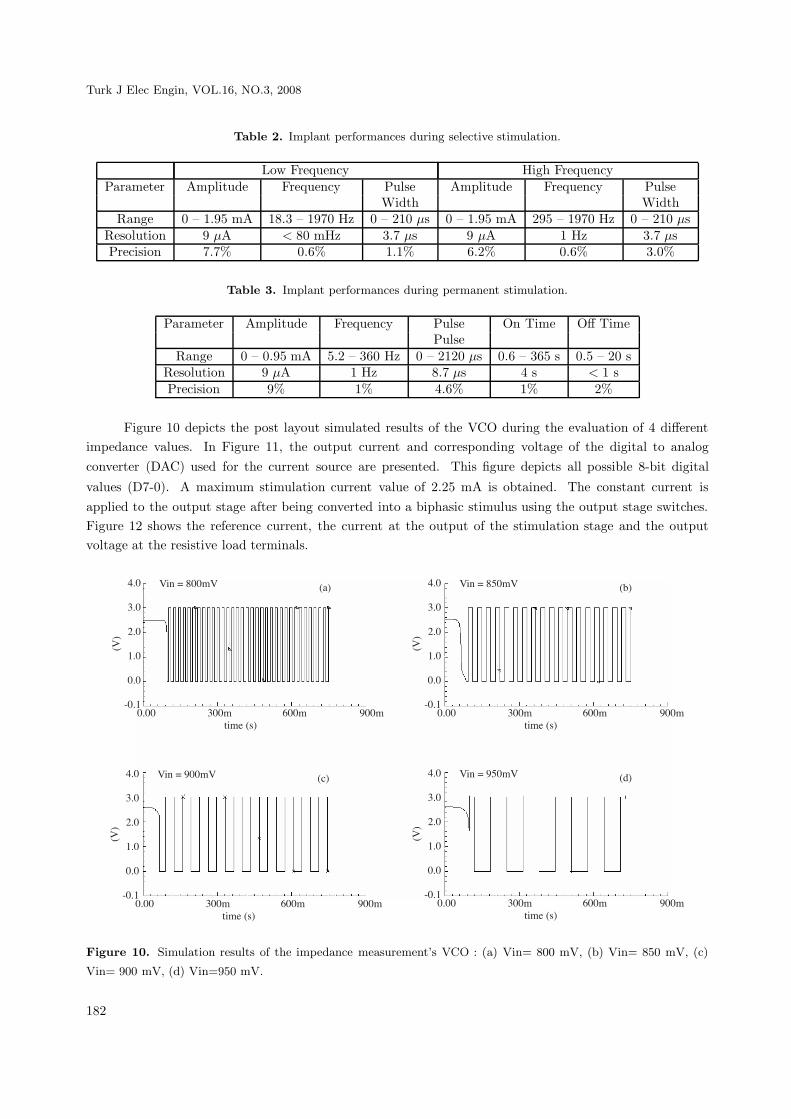
Table 2. Implant performances during selective stimulation.
Low Frequency High FrequencyParameter Amplitude Frequency Pulse Amplitude Frequency Pulse
Width WidthRange 0 – 1.95 mA 18.3 – 1970 Hz 0 – 210 μs 0 – 1.95 mA 295 – 1970 Hz 0 – 210 μs
Resolution 9 μA < 80 mHz 3.7 μs 9 μA 1 Hz 3.7 μsPrecision 7.7% 0.6% 1.1% 6.2% 0.6% 3.0%
Table 3. Implant performances during permanent stimulation.
Parameter Amplitude Frequency Pulse On Time Off TimePulse
Range 0 – 0.95 mA 5.2 – 360 Hz 0 – 2120 μs 0.6 – 365 s 0.5 – 20 sResolution 9 μA 1 Hz 8.7 μs 4 s < 1 sPrecision 9% 1% 4.6% 1% 2%
Figure 10 depicts the post layout simulated results of the VCO during the evaluation of 4 differentimpedance values. In Figure 11, the output current and corresponding voltage of the digital to analogconverter (DAC) used for the current source are presented. This figure depicts all possible 8-bit digital
values (D7-0). A maximum stimulation current value of 2.25 mA is obtained. The constant current isapplied to the output stage after being converted into a biphasic stimulus using the output stage switches.Figure 12 shows the reference current, the current at the output of the stimulation stage and the outputvoltage at the resistive load terminals.
5&?
%&?
�&?
*&?
?&?
$?&*
.#/
?&?? %??� @??� A??�����4.�/
.�/#��4B49??�# 5&?
%&?
�&?
*&?
?&?
$?&*
.#/
?&?? %??� @??� A??�����4.�/
.3/#��4B49"?�#
5&?
%&?
�&?
*&?
?&?
$?&*
.#/
?&?? %??� @??� A??�����4.�/
.�/#��4B4A"?�#5&?
%&?
�&?
*&?
?&?
$?&*
.#/
?&?? %??� @??� A??�����4.�/
.�/#��4B4A??�#
Figure 10. Simulation results of the impedance measurement’s VCO : (a) Vin= 800 mV, (b) Vin= 850 mV, (c)
Vin= 900 mV, (d) Vin=950 mV.
182

SAWAN, BA, MOUNAIM, CORCOS, ELHILALI: Biomedical Circuits and Systems Dedicated for...,
5&?
%&?
�&?
*&?
.#/
*??
%&?
�&?
*&?
?&?
.�/
67�0
�?? %??����4.�/
6���4B4�&�"��
#7�0
.�/
.3/
��������4��(��(4��������
Figure 11. Simulation results of the DAC: (a) Output Voltage, (b) Output current after amplification.
$"@?
$"@"
$"C?
.�/
*&A�
*&9�
*&C
*&@�
.�/
*&???????
*&%%%%%%%
*&%%%%%%%
5&???????
.#/
6 ��4B4"@5�
.�/
6��4B4*&C"��
#��4B4�&@%#.3/
?&? 5&? 9&? *� *@ �?.�/
7���4���<�7���4-����� �
Figure 12. Simulation results of the output stage: (a) Reference current from DAC, (b) Output current after
amplification, (c) Waveform of the applied stimulation voltage.
Figure 13 shows the fabricated chip in a CMOS 0.18 um process, which occupies 4 mm2 . Theexperimental results of the fabricated chip demonstrates its functionality, as shown in Figure 14. Themicrostimulator generates a wide range of stimuli with variable parameters. The high frequency waveformsrange from 294 Hz to 75 KHz, while the low frequency ranges from 4.6 Hz to 1.2 KHz. The VCO frequencygoes from 50 Hz to 300 KHz allowing the detection of short and open circuits. The pulse durations varyfrom 3 μs to 853 μs. Also, up to 32 8-bit values can be stored in the RAM, allowing the generation offlexible stimulation waveforms.
183

Turk J Elec Engin, VOL.16, NO.3, 2008
��<���4�� �
#���<� �<�
���������('����4*
���������('����4�
Figure 13. Chip microphotography of the integrated microstimulator.
(a) (b)
(c)
Figure 14. Measurement results from the integrated microstimulator (a) Selective high and low frequency stimula-
tion, (b) Stimulation with arbitrary pattern, (c) Permanent stimulation with train of pulses.
4.1. Conclusion
We described in this paper functional stimulation systems dedicated to the rehabilitation of the urinaryfunctions. An implant and a new integrated stimulator were described. We presented the experimental results
184
SAWAN, BA, MOUNAIM, CORCOS, ELHILALI: Biomedical Circuits and Systems Dedicated for...,
of the implantable stimulator. The reliability and the real lifetime of the battery of the implant were verifiedin the long run during in-vivo tests. These results were presented in previous works [35]. Experimental resultsof the stimulation strategies and dedicated implantable stimulators confirmed the reliability of the selectivehigh frequency blockage stimulation for long term bladder voiding in paraplegics. Also, the neuromodulationtechnique, based on permanent low frequency and low amplitude current stimulation, appeared to be apromising solution to cure the neurogenic detrusor over activity with no drawback. On the other hand, thedesign and implementation of the integrated microstimulator, by combining multiple stimulation techniqueswith a proven efficiency, address at the same time the requirements that most stimulation systems lack suchas flexibility, reliability and reprogrammability. This microstimulator needs to be validated in a real in-vivoenvironment to validate the results obtained with the previous versions and to confirm that the proposedtechniques constitutes an adequate solution for a complete rehabilitation of the urinary bladder functions.More tests need to be performed regarding power consumption and management. Adequate packagingsolutions will also be a priority.
Acknowledgements
The authors would like to acknowledge the financial support from the Natural Sciences and EngineeringResearch Council of Canada (NSERC), the Canadian Institutes of Health Research (CIHR), and the CanadaResearch Chair on smart medical devices, and the design and fabrication facilities for CMC Microsystems.Thanks are also due to E. Schneider for his contributions to this project.
References
[1] M. Sawan, Y. Hu, J. Coulombe, “Wireless Smart Implants Dedicated to Multichannel Monitoring and Micros-
timulation”, Invited paper in IEEE Circuits and Systems Magazine, Vol. 5, pp. 21-39, 2005.
[2] J. Coulombe, M. Sawan, J. F. Gervais, “A Highly Flexible System for Microstimulation of the Visual Cortex:
Design and Implementation”, IEEE Trans. on Biomedical Circuits & Systems, Vol. 1, No. 4, pp. 258-269,
December 2007.
[3] M. Sawan, “Biomedical Circuits and Systems Dedicated for Sensing and Neurostimulation”, Lecture at ELECO,
Bursa, Turkey, Dec. 2007.
[4] D. Buback, “The use of neuromodulation for treatment of urinary incontinence”, AORN Journal, 73:176-190,
2001.
[5] J. Walter, R. Sidarous, C. J. Robinson, J. S. Wheeler, R. D. Wurster, “Comparison of direct bladder and sacral
nerve stimulation in spinal cats”, Journal of Rehab. Res. and Dev., 29, 2:13-22, 1992.
[6] J. P. Heine, R. A. Schmidt, E. A. Tanagho, “Intraspinal sacral root stimulation for controlled micturition”,
Invest. Urol.,15:78, 1977.
[7] W. E. Bradley, G. W. Timm, S. N. Chou, “A decade of experience with electronic stimulation of the micturition
reflex”, Urol. Int., 26:283, 1971.
[8] H. N. Habib, “Experience and recent contributions in sacral nerve stimulation for both human and animal”, Br.
J. Urol., 39:73, 1967.
185

Turk J Elec Engin, VOL.16, NO.3, 2008
[9] R. A. Schmidt, H. Bruschini, E. A. Tanagho, “Urinary bladder and sphincter responses to stimulation of dorsal
and ventral sacral roots”, Invest. Urol, 16:300, 1979.
[10] A. S. Haleem, F. Boehm, A. D. Legatt, A. Kantrowitz, B. Stone, A. Melman, “Sacral root stimulation for
controlled micturition: Prevention of detrusor-external sphincter dyssynergia by intraoperative identification
and selective section of sacral nerve branches”, Journal of Urol, 149:1607-1612, 1993.
[11] A. Tallala, J. W. Bloom, N. Quang, “FES for Bladder: Direct or indirect Means? ”, PACE, 10:240-245, 1987.
[12] N. J. M. Rijkhoff, H. Wikstra, P. E. V. Van Kerrebroeck, F.M.J. Debruyne, “Urinary bladder control by electrical
stimulation: review of electrical stimulation techniques in spinal cord injury”, Neurourol. Urodynam, 16:39-53,
1997.
[13] B. Holmquist, W.J. Staubitz, “The role of the pudendal nerve in connections with electronic emptying of the
neurogenic cord bladder in dogs”, Journal of Urol., 91:41-54, 1964.
[14] B. S. Nashold, H. Friedman, J. H. Glen, J. H. Grimes, W. F. Barry, R. Avery, “Electromicturition in paraplegia”,
Arch. Surg., 104:195, 1972.
[15] H. Friedman, B. S. Jr. Nashold, J. Grimes, “Electrical Stimulation of the Conus Medullaris in the paraplegic
- A five year review”, In FT hambrecht, JB Reswick (eds): Functionnal electrical stimulation, New York and
Basel: Marcel Dekker, Inc, 173, 1977.
[16] G. S. Brindley, C. S. Polkey, D. N. Rushton, “Sacral anterior root stimulators for bladder control in paraplegia”,
Paraplegia, 20:365, 1982.
[17] G. S. Brindley “An implant to empty the bladder or close the urethra”, Journal of Neurology, Neurosurgery,
and Psychiatry, 40:358-369, 1977.
[18] J. S. Li, M. Hassouna, M. Sawan, F. Duval, M. M. Elhilali, “Long-term effect of sphincteric fatigue during
bladder neurostimulation”, The journal of Urol., 153:238-242, 1995.
[19] M. Sawan, M. Hassouna, J. S. Li, F. Duval, M. M. Elhilali, “Stimulator design and subsequent stimulation
parameter optimization for controlling micturition and reducing urethral resistance”, IEEE Transactions on
Rehabilitation Engineering, 4, 1:39-46, 1996.
[20] J. D. Sweeney, J. T. Mortimer, D. R. Bodner, “Acute animal studies on electrically induced collision block of
pudendal nerve motor activities”, Neurourolog. Urodyn., 8:521, 1989.
[21] G. S. Brindley, M. D. Craggs, “A technique for anodally blocking large nerve fibers through chronically implanted
electrodes, ” J. Neurol. Neurosurg. Psychiatry, 1980, 43:1083.
[22] E. L. Koldewijn, N. J. Rijkhoff, Ph. E. V. Van Kerrebroeck, F. M. J. Debreyne, H. Wijkstra, “Selective sacral
root stimulation for bladder control: Acute experiments in a animal model”, Journal of Urol., 151:1674, 1992.
[23] M. Ishigooka, T. Hashimoto, I. Sasagawa, K. Izumiya, T. Nakada, “Modulation of the urethral pressure by
high-frequency block stimulus in dogs”, Eur. Urol., 25:334, 1994.
[24] H. S. Shaker, L. M. Tu, S. Robin, K. Arabi, M. Hassouna, M. Sawan, M. M. Elhilali, “Reduction of bladder
outlet resistance by selective sacral root stimulation using high-frequency blockade in dogs : An acute study”,
The Journal of Urol., Vol. 160: 901-907, 1998.
[25] N. Accornero, G. Bini, G. L. Lenzi, M. Manfredi, “Selective activation of peripheral nerve fiber groups of different
diameter by triangular shaped stimulus pulses”, Journal Physiol., 273:539-560, 1977.
186

SAWAN, BA, MOUNAIM, CORCOS, ELHILALI: Biomedical Circuits and Systems Dedicated for...,
[26] Z. P. Fang, J. T. Mortimer, “Selective activation of small motor axons by quasitrapezoidal current pulses”, IEEE
Trans. Biomed. Eng., 38:168-174, 1991.
[27] S. Robin, M. Sawan, M. Abdel-Gawad, T.M. Abdel-Baky, M.M. Elhilali, “Implantable stimulation system
dedicated for neural selective stimulation”, Medical & Biological Engineering & Computing Vol. 36, No. 4, pp.
490-492, 1998.
[28] P. Magasi, Z. Simon, “Electrical stimulation of the bladder and gravidity”, Urology International, No. 41:241-
245, 1986.
[29] T. A. Perkins, “Versatile Three-channel stimulation controller for restoration of bladder functions in paraplegia”,
Journal of Biomed. Eng., Vol. 8:268-271, 1986.
[30] ——-, “Interstim therapy for urinary control”, Medtronic Neurological Inc., Minneapolis, 1999.
[31] ——-, “Implantable functional neuromuscular stimulator”, Vocare bladder system, Neurocontrol Corporation,
Ohio, 1998.
[32] K. Arabi, M. Sawan, “Implantable multiprogrammable microstimulator dedicated to bladder control”, Medical
& Biological Engineering & Computing, 34:9-12, 1996.
[33] E. Schneider, A. M. Abdel-Karim, M. Sawan, M. M. Elhilali, “New stimulation strategy to improve the bladder
function in paraplegics: Chronic experiments in dogs”, 23rd IEEE Int. Conf. of Eng. in Medicine and Biology
Society, Istanbul, Turkey, 2001.
[34] S. Boyer, M. Sawan, M. Abdel-Gawad, S. Robin, M. M. Elhilali, “Implantable selective stimulator improve
bladder voiding: design and chronic experiments in dogs”, IEEE Transactions on Rehabilitation Engineering,
8:764-470, 2000.
[35] A. Ba, E. Schneider, A. M. Abdel-Karim, M. Sawan, M. M. Elhilali, “Implantable dual stimulator to recuperate
the bladder functions: Chronic experiments in dogs”, IFESS, Slovenia, 2002.
[36] M. A. Crampon, M. Sawan, V. Brailovski, F. Trochu, “New easy to install nerve cuff electrode using SMA
armature”, Artificial Organs Journal, 23, 5:392-395, 1999.
[37] T. Stiegliz, T. Matal, M. Staemmler, “A modular multichannel stimulator for arbitrary shaped current pulses for
experimental and clinical use in FES”, Proceedings of the 19th International Conference IEEE/EMBS, Illinois,
1997.
[38] C. Donfack, M. Sawan, Y. Savaria, “An implantable measurement technique dedicated to the monitoring of
electrodes-nerve contact in bladder stimulators”, Medical & Biological Engineering & Computing, 38:465-568,
2000.
187