Embed Size (px)
Citation preview
Materials Today � Volume 16, Number 6 � June 2013 RESEARCH
Biomimetic electrospun nanofibrousstructures for tissue engineeringXianfeng Wang1,2, Bin Ding2 and Bingyun Li1,3,*
1Department of Orthopaedics, School of Medicine, West Virginia University, Morgantown, WV 26506, United States2 State Key Laboratory for Modification of Chemical Fibers and Polymer Materials, College of Materials Science and Engineering, Donghua University,Shanghai 201620, China3WVNano Initiative, Morgantown, WV 26506, United States
Biomimetic nanofibrous scaffolds mimicking important features of the native extracellular matrix
provide a promising strategy to restore functions or achieve favorable responses for tissue regeneration.
This review provides a brief overview of current state-of-the-art research designing and using biomimetic
electrospun nanofibers as scaffolds for tissue engineering. It begins with a brief introduction of
electrospinning and nanofibers, with a focus on issues related to the biomimetic design aspects. The
review next focuses on several typical biomimetic nanofibrous structures (e.g. aligned, aligned to
random, spiral, tubular, and sheath membrane) that have great potential for tissue engineering scaffolds,
and describes their fabrication, advantages, and applications in tissue engineering. The review concludes
with perspectives on challenges and future directions for design, fabrication, and utilization of scaffolds
based on electrospun nanofibers.
IntroductionTissue engineering is an emerging interdisciplinary field that
applies biological and engineering principles to develop biological
substitutes that restore, maintain, or improve tissue function [1–
4]. It usually requires a scaffold to provide a transitional three-
dimensional (3D) support for cell migration, attachment, and
proliferation, as well as to provide a vector for delivery of bio-
chemical factors [5,6]. The scaffold should also offer mechanical as
well as biological influences to guide the maturation and integra-
tion of cells to form tissues [7]. Therefore, the major challenge in
tissue engineering is to design and fabricate a suitable scaffold to
fulfill the growing needs of the field.
With increasing understanding of the intricate interactions
between cells and their microenvironment in tissues, more atten-
tion is now focused on the preparation of scaffolds that can imitate
the componential and structural aspects of extracellular matrix
(ECM) to facilitate cell recruiting/seeding, adhesion, proliferation,
differentiation, and neo tissue genesis [3,8,9]. From a structural
perspective, natural ECM consists of various interwoven protein
fibers with diameters ranging from tens to hundreds of nan-
ometers [10]. The nanoscale structure of ECM offers a natural
network of nanofibers to support cells and to present an instructive
background to guide cell behavior [11,12]. Developing scaffolds
that imitate the architecture of tissues at the nanoscale is one of
the major challenges in the field of tissue engineering [13–15]. The
development of nanofibers has greatly improved the scope for
preparing scaffolds that can imitate the architecture of natural
human tissues at the nanoscale [16].
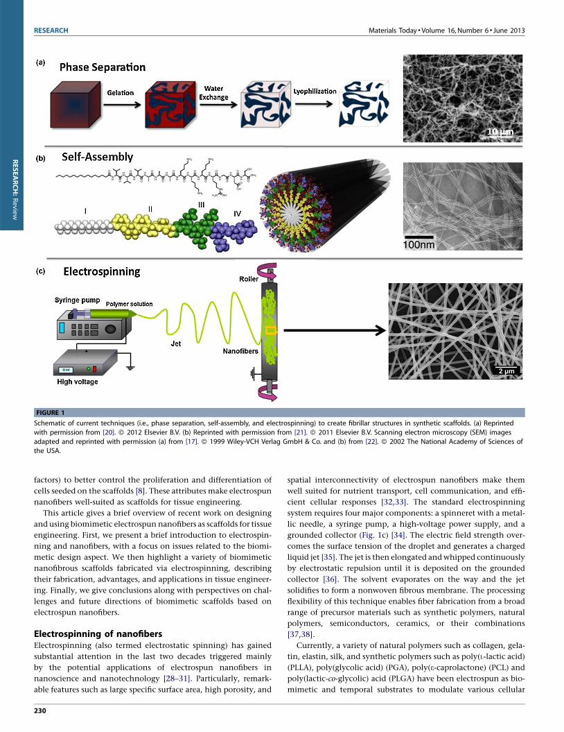
Various processing techniques (e.g. phase separation, self-
assembly, and electrospinning) have been developed to fabricate
nanofibrous scaffolds to be used as ECM substitutes (Fig. 1) [9,17–
22]. Among them, the electrospinning process has attracted sig-
nificant attention because of its ability to generate fibers similar to
the fibrous structures of native ECM (Fig. 1c) and to process a wide
range of materials, as well as the straightforward nature of the
process and its cost-effectiveness [23,24]. The large surface area of
electrospun nanofibers as well as their porous structure favors cell
adhesion, proliferation, migration, and differentiation [25–27]. If
necessary, the nanofibers can be further functionalized via incor-
poration with bioactive species (e.g. enzymes, DNAs, and growth
RESEARCH:Review
*Corresponding author: Li, B. ([email protected])
1369-7021/06� 2013 Elsevier Ltd. http://dx.doi.org/10.1016/j.mattod.2013.06.005 229Open access under CC BY-NC-ND license.
factors) to better control the proliferation and differentiation of
cells seeded on the scaffolds [8]. These attributes make electrospun
nanofibers well-suited as scaffolds for tissue engineering.
This article gives a brief overview of recent work on designing
and using biomimetic electrospun nanofibers as scaffolds for tissue
engineering. First, we present a brief introduction to electrospin-
ning and nanofibers, with a focus on issues related to the biomi-
metic design aspect. We then highlight a variety of biomimetic
nanofibrous scaffolds fabricated via electrospinning, describing
their fabrication, advantages, and applications in tissue engineer-
ing. Finally, we give conclusions along with perspectives on chal-
lenges and future directions of biomimetic scaffolds based on
electrospun nanofibers.
Electrospinning of nanofibersElectrospinning (also termed electrostatic spinning) has gained
substantial attention in the last two decades triggered mainly
by the potential applications of electrospun nanofibers in
nanoscience and nanotechnology [28–31]. Particularly, remark-
able features such as large specific surface area, high porosity, and
spatial interconnectivity of electrospun nanofibers make them
well suited for nutrient transport, cell communication, and effi-
cient cellular responses [32,33]. The standard electrospinning
system requires four major components: a spinneret with a metal-
lic needle, a syringe pump, a high-voltage power supply, and a
grounded collector (Fig. 1c) [34]. The electric field strength over-
comes the surface tension of the droplet and generates a charged
liquid jet [35]. The jet is then elongated and whipped continuously
by electrostatic repulsion until it is deposited on the grounded
collector [36]. The solvent evaporates on the way and the jet
solidifies to form a nonwoven fibrous membrane. The processing
flexibility of this technique enables fiber fabrication from a broad
range of precursor materials such as synthetic polymers, natural
polymers, semiconductors, ceramics, or their combinations
[37,38].
Currently, a variety of natural polymers such as collagen, gela-
tin, elastin, silk, and synthetic polymers such as poly(L-lactic acid)
(PLLA), poly(glycolic acid) (PGA), poly(e-caprolactone) (PCL) and
poly(lactic-co-glycolic) acid (PLGA) have been electrospun as bio-
mimetic and temporal substrates to modulate various cellular
RESEARCH Materials Today � Volume 16, Number 6 � June 2013
[(Figure_1)TD$FIG]
FIGURE 1
Schematic of current techniques (i.e., phase separation, self-assembly, and electrospinning) to create fibrillar structures in synthetic scaffolds. (a) Reprinted
with permission from [20]. � 2012 Elsevier B.V. (b) Reprinted with permission from [21]. � 2011 Elsevier B.V. Scanning electron microscopy (SEM) images
adapted and reprinted with permission (a) from [17]. � 1999 Wiley-VCH Verlag GmbH & Co. and (b) from [22]. � 2002 The National Academy of Sciences ofthe USA.
230
RESEARCH:Review
activities. However, syntheticor naturalpolymer alone cannotmeet
all the requirements for tissue engineering. Syntheticpolymers have
great flexibility in synthesis and modification, but these polymers
lack cell affinity because of their low hydrophilicity and lack of
surface cell recognition sites. Compared with synthetic polymers,
natural polymers provide good biocompatibility but tend to display
poor processing ability and mechanical properties [32]. Therefore, it
is desirable to fabricate composite fibrous membranes comprising
both synthetic polymers for the backbone and natural polymers for
cellular attachment,whichmightpossessnotonly suitablemechan-
ical properties but also a bioactive surface [39].
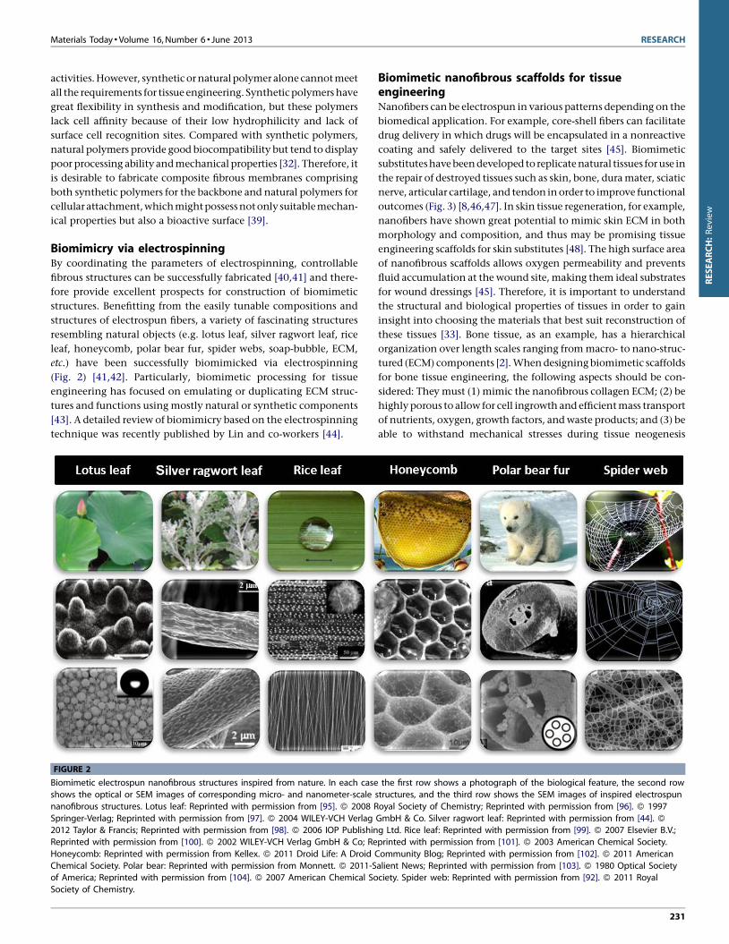
Biomimicry via electrospinningBy coordinating the parameters of electrospinning, controllable
fibrous structures can be successfully fabricated [40,41] and there-
fore provide excellent prospects for construction of biomimetic
structures. Benefitting from the easily tunable compositions and
structures of electrospun fibers, a variety of fascinating structures
resembling natural objects (e.g. lotus leaf, silver ragwort leaf, rice
leaf, honeycomb, polar bear fur, spider webs, soap-bubble, ECM,
etc.) have been successfully biomimicked via electrospinning
(Fig. 2) [41,42]. Particularly, biomimetic processing for tissue
engineering has focused on emulating or duplicating ECM struc-
tures and functions using mostly natural or synthetic components
[43]. A detailed review of biomimicry based on the electrospinning
technique was recently published by Lin and co-workers [44].
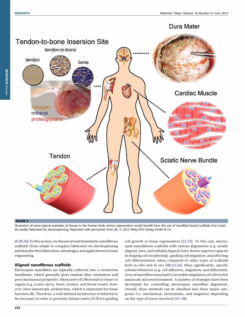
Biomimetic nanofibrous scaffolds for tissueengineeringNanofibers can be electrospun in various patterns depending on the
biomedical application. For example, core-shell fibers can facilitate
drug delivery in which drugs will be encapsulated in a nonreactive
coating and safely delivered to the target sites [45]. Biomimetic
substituteshave beendeveloped toreplicatenatural tissues for use in
the repair of destroyed tissues such as skin, bone, dura mater, sciatic
nerve, articular cartilage, and tendon in order to improve functional
outcomes (Fig. 3) [8,46,47]. In skin tissue regeneration, for example,
nanofibers have shown great potential to mimic skin ECM in both
morphology and composition, and thus may be promising tissue
engineering scaffolds for skin substitutes [48]. The high surface area
of nanofibrous scaffolds allows oxygen permeability and prevents
fluid accumulation at the wound site, making them ideal substrates
for wound dressings [45]. Therefore, it is important to understand
the structural and biological properties of tissues in order to gain
insight into choosing the materials that best suit reconstruction of
these tissues [33]. Bone tissue, as an example, has a hierarchical
organization over length scales ranging from macro- to nano-struc-
tured (ECM) components [2]. When designing biomimetic scaffolds
for bone tissue engineering, the following aspects should be con-
sidered: They must (1) mimic the nanofibrous collagen ECM; (2) be
highly porous to allow for cell ingrowth and efficient mass transport
of nutrients, oxygen, growth factors, and waste products; and (3) be
able to withstand mechanical stresses during tissue neogenesis
Materials Today � Volume 16, Number 6 � June 2013 RESEARCH
[(Figure_2)TD$FIG]
FIGURE 2
Biomimetic electrospun nanofibrous structures inspired from nature. In each case the first row shows a photograph of the biological feature, the second row
shows the optical or SEM images of corresponding micro- and nanometer-scale structures, and the third row shows the SEM images of inspired electrospun
nanofibrous structures. Lotus leaf: Reprinted with permission from [95]. � 2008 Royal Society of Chemistry; Reprinted with permission from [96]. � 1997
Springer-Verlag; Reprinted with permission from [97]. � 2004 WILEY-VCH Verlag GmbH & Co. Silver ragwort leaf: Reprinted with permission from [44]. �2012 Taylor & Francis; Reprinted with permission from [98]. � 2006 IOP Publishing Ltd. Rice leaf: Reprinted with permission from [99]. � 2007 Elsevier B.V.;
Reprinted with permission from [100]. � 2002 WILEY-VCH Verlag GmbH & Co; Reprinted with permission from [101]. � 2003 American Chemical Society.
Honeycomb: Reprinted with permission from Kellex. � 2011 Droid Life: A Droid Community Blog; Reprinted with permission from [102]. � 2011 American
Chemical Society. Polar bear: Reprinted with permission from Monnett. � 2011-Salient News; Reprinted with permission from [103]. � 1980 Optical Societyof America; Reprinted with permission from [104]. � 2007 American Chemical Society. Spider web: Reprinted with permission from [92]. � 2011 Royal
Society of Chemistry.
231
RESEARCH:Review
[9,49,50]. In this section, we discuss several biomimetic nanofibrous
scaffolds (from simple to complex) fabricated via electrospinning
and describe their fabrication, advantages, and applications in tissue
engineering.
Aligned nanofibrous scaffoldsElectrospun nanofibers are typically collected into a nonwoven
membrane, which generally gives random fiber orientation and
poor mechanical properties. Most native ECMs found in tissues or
organs (e.g. sciatic nerve, heart, tendon, and blood vessel), how-
ever, have anisotropic architecture, which is important for tissue
function [8]. Therefore, a well-defined architecture is believed to
be necessary in order to precisely imitate native ECM for guiding
cell growth or tissue regeneration [51,52]. To this end, electro-
spun nanofibrous scaffolds with various alignments (e.g. axially
aligned, yarn, and radially aligned) have shown superior capacity
in shaping cell morphology, guiding cell migration, and affecting
cell differentiation when compared to other types of scaffolds
both in vitro and in vivo [48,53,54]. More significantly, specific
cellular behaviors (e.g. cell adhesion, migration, and differentia-
tion) of nanofibers may lead to favorable adaptation of cells in this
nanoscale microenvironment. A number of strategies have been
developed for controlling electrospun nanofiber alignment.
Overall, these methods can be classified into three major cate-
gories (i.e. mechanical, electrostatic, and magnetic) depending
on the type of forces involved [55–58].
RESEARCH Materials Today � Volume 16, Number 6 � June 2013
[(Figure_3)TD$FIG]
FIGURE 3
Illustration of some typical examples of tissues in the human body whose regeneration would benefit from the use of nanofiber-based scaffolds that could
be readily fabricated by electrospinning. Reprinted with permission from [8]. � 2012 Wiley-VCH Verlag GmbH & Co.
232
RESEARCH:Review
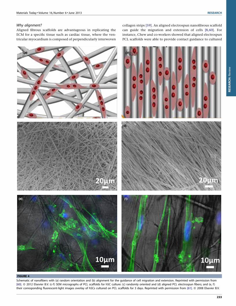
Why alignment?Aligned fibrous scaffolds are advantageous in replicating the
ECM for a specific tissue such as cardiac tissue, where the ven-
tricular myocardium is composed of perpendicularly interwoven
collagen strips [59]. An aligned electrospun nanofibrous scaffold
can guide the migration and extension of cells [8,60]. For
instance, Chew and co-workers showed that aligned electrospun
PCL scaffolds were able to provide contact guidance to cultured
Materials Today � Volume 16, Number 6 � June 2013 RESEARCH
[(Figure_4)TD$FIG]
FIGURE 4
Schematic of nanofibers with (a) random orientation and (b) alignment for the guidance of cell migration and extension. Reprinted with permission from
[60]. � 2012 Elsevier B.V. (c-f ) SEM micrographs of PCL scaffolds for hSC culture: (c) randomly oriented and (d) aligned PCL electrospun fibers; and (e, f )
their corresponding fluorescent-light images overlay of hSCs cultured on PCL scaffolds for 3 days. Reprinted with permission from [61]. � 2008 Elsevier B.V.
233
RESEARCH:Review
human Schwann cells (hSCs), resulting in an elongation and
alignment of cells along the axes of the fibers [61]. As shown
in Fig. 4, the effect of contact guidance provided by the aligned
fibers appeared to be more dramatic than the randomly oriented
fibers. When cultured on aligned fibers, the cytoskeleton and
nuclei align and elongate on the fiber axes. The effect of contact
guidance of aligned electrospun fibers on cell morphological
changes was also evident in other cell types (e.g. neural stem
cell) [62].
Applications of aligned nanofibrous scaffolds in tissueengineeringSignificant efforts have been made in the development of aligned
nanofibrous structures as tissue-engineered scaffolds for bone
[63,64], cartilage [65], dural [53], and other tissues. Natural bone
has significant anisotropic mechanical properties with highly
oriented ECM and bone cells. Therefore, aligned electrospun nano-
fibers show great potential as a bone tissue engineering scaffold. Jose
et al. [63] demonstrated that uniaxially aligned PLGA/hydroxyapa-
tite nanofibrouscomposite membranes could serve as ideal scaffolds
for bone tissue engineering and found that the concentration of
hydroxyapatite in the composites played an important role in the
structure and mechanical behavior of the scaffolds.
Apart from uniaxially aligned nanofibers, some other unique
biomimetic aligned fibrous structures have also been developed for
tissue engineering applications. Electrospun 3D nanofibrous
matrices with high spatial interconnectivity, high porosity, and
controlled alignment have been well studied to direct cell orienta-
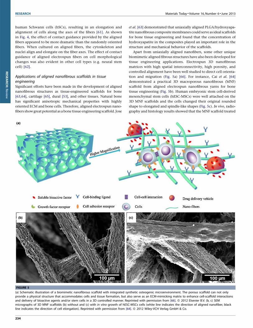
tion and migration (Fig. 5a) [66]. For instance, Cai et al. [64]
demonstrated a practical 3D macroporous nanofibrous (MNF)
scaffold from aligned electrospun nanofibrous yarns for bone
tissue engineering (Fig. 5b). Human embryonic stem cell-derived
mesenchymal stem cells (hESC-MSCs) were well attached on the
3D MNF scaffolds and the cells changed their original rounded
shape to elongated and spindle-like shapes (Fig. 5c). In vivo, radio-
graphy and histology results showed that the MNF scaffold treated
RESEARCH Materials Today � Volume 16, Number 6 � June 2013
[(Figure_5)TD$FIG]
FIGURE 5
(a) Schematic illustration of a biomimetic nanofibrous scaffold with integrated synthetic osteogenic microenvironment. The porous scaffold can not only
provide a physical structure that accommodates cells and tissue formation, but also serve as an ECM-mimicking matrix to enhance cell-scaffold interactions
and delivery of bioactive agents and/or stem cells in a 3D controlled manner. Reprinted with permission from [66]. � 2012 Elsevier B.V. (b, c) SEMmicrographs of 3D MNF scaffolds (b) without and (c) with in vitro growth of hESC-MSCs cells (white line indicates the direction of aligned nanofiber, black
line indicates the direction of cell elongation). Reprinted with permission from [64]. � 2012 Wiley-VCH Verlag GmbH & Co.
234
RESEARCH:Review
bone defect had fine 3D bony tissue formation around the scaffold
as well as inside the scaffold at 6 weeks. This study demonstrated
that the 3D MNF scaffold could provide a structural support for
hESC-MSC growth and guide bone formation, which may help
promote the clinical translation of electrospun nanofibers for
regenerative medicine in the future [64].
To imitate the dura mater and to develop artificial dural sub-
stitutes to promote cell migration from the surrounding tissue to
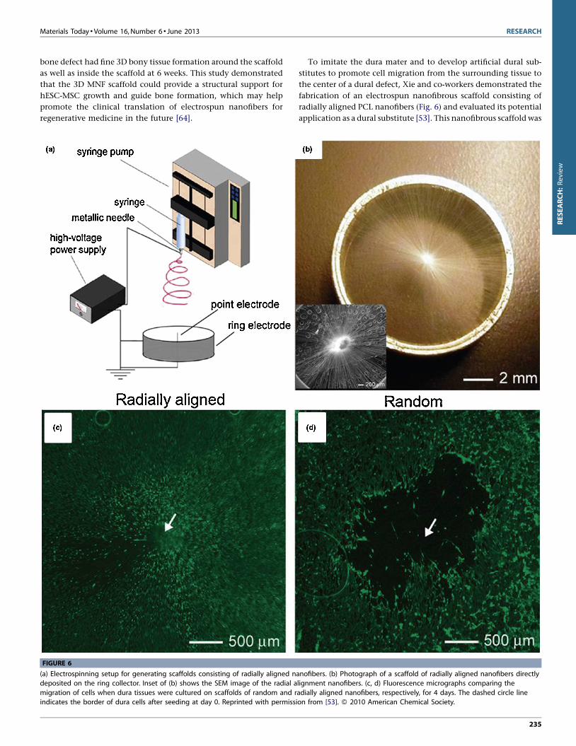
the center of a dural defect, Xie and co-workers demonstrated the
fabrication of an electrospun nanofibrous scaffold consisting of
radially aligned PCL nanofibers (Fig. 6) and evaluated its potential
application as a dural substitute [53]. This nanofibrous scaffold was
Materials Today � Volume 16, Number 6 � June 2013 RESEARCH
[(Figure_6)TD$FIG]
FIGURE 6
(a) Electrospinning setup for generating scaffolds consisting of radially aligned nanofibers. (b) Photograph of a scaffold of radially aligned nanofibers directly
deposited on the ring collector. Inset of (b) shows the SEM image of the radial alignment nanofibers. (c, d) Fluorescence micrographs comparing the
migration of cells when dura tissues were cultured on scaffolds of random and radially aligned nanofibers, respectively, for 4 days. The dashed circle line
indicates the border of dura cells after seeding at day 0. Reprinted with permission from [53]. � 2010 American Chemical Society.
235
RESEARCH:Review
RESEARCH Materials Today � Volume 16, Number 6 � June 2013
[(Figure_7)TD$FIG]
FIGURE 7
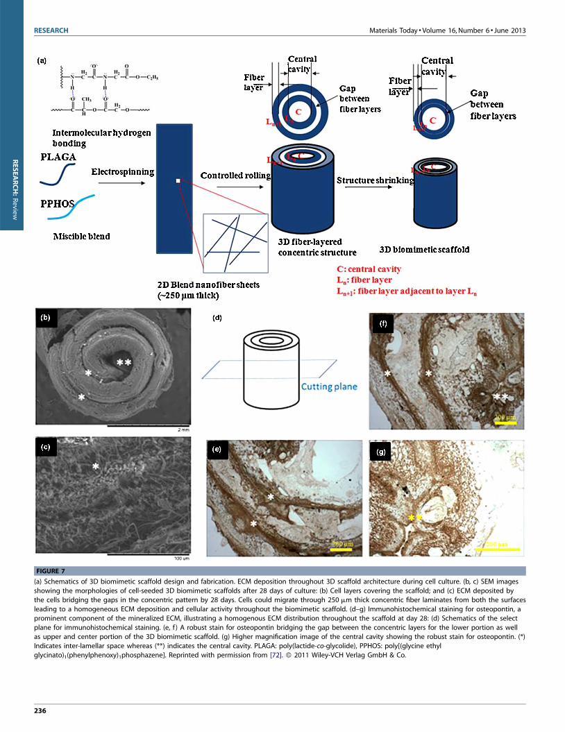
(a) Schematics of 3D biomimetic scaffold design and fabrication. ECM deposition throughout 3D scaffold architecture during cell culture. (b, c) SEM images
showing the morphologies of cell-seeded 3D biomimetic scaffolds after 28 days of culture: (b) Cell layers covering the scaffold; and (c) ECM deposited bythe cells bridging the gaps in the concentric pattern by 28 days. Cells could migrate through 250 mm thick concentric fiber laminates from both the surfaces
leading to a homogeneous ECM deposition and cellular activity throughout the biomimetic scaffold. (d–g) Immunohistochemical staining for osteopontin, a
prominent component of the mineralized ECM, illustrating a homogenous ECM distribution throughout the scaffold at day 28: (d) Schematics of the select
plane for immunohistochemical staining. (e, f ) A robust stain for osteopontin bridging the gap between the concentric layers for the lower portion as wellas upper and center portion of the 3D biomimetic scaffold. (g) Higher magnification image of the central cavity showing the robust stain for osteopontin. (*)
Indicates inter-lamellar space whereas (**) indicates the central cavity. PLAGA: poly(lactide-co-glycolide), PPHOS: poly[(glycine ethyl
glycinato)1(phenylphenoxy)1phosphazene]. Reprinted with permission from [72]. � 2011 Wiley-VCH Verlag GmbH & Co.
236
RESEARCH:Review
prepared by utilizing a collector composed of a central point
electrode and a peripheral ring electrode (Fig. 6a and b). They
demonstrated that this novel class of scaffolds was able to present
nanoscale topographic cues to cultured cells, directing and enhan-
cing their migration from the periphery to the center. As shown in
Fig. 6c, dural fibroblasts stained with fluorescein diacetate (FDA)
migrated from the surrounding tissue along the radially aligned
nanofibers toward the center of the circular scaffold after incuba-
tion for 4 days. In contrast, a void was observed after the same
period of incubation time for a scaffold made of random fibers
(Fig. 6d), indicating a faster migration rate for the cells on radially
aligned nanofibers. Scaffolds based on radially aligned, electro-
spun nanofibers show great potential as artificial dural substitutes
and may be particularly useful as biomedical patches or grafts to
induce wound closure and tissue regeneration.
Aligned to random nanofibrous scaffoldsTendons are the connective tissues that bridge muscle to bone and
allow transmission of forces to produce joint movement [67]. They
are attached to bones across a specialized transitional tissue with
varying structures and compositions. Tendon-related injuries are
among the most common injuries to the body. The clinical repair
of a tendon-to-bone insertion site often fails due to the lack of
regeneration of the complex transitional tissue that normally exits
at the uninjured attachment [8,68]. To imitate the gradients in
composition and structure that exist at the uninjured tendon-to-
bone insertion, Li et al. [69] demonstrated the fabrication of a
gradient of mineral on the surface of a nanofiber-based scaffold,
which could imitate the composition and mechanical function of
the tendon-to-bone insertion site. They also demonstrated the
fabrication of a nanofibrous scaffold with an ‘‘aligned-to-random’’
transition in the same scaffold by utilization of a specially designed
collector, which could imitate the structural organization of col-
lagen fibers at the tendon-to-bone insertion site [67]. Specifically,
the aligned portion could imitate the high level of alignment for
collagen fibers in a normal tendon and the random portion could
recapitulate the less ordered organization of collagen fibers in a
bone. Tendon fibroblasts cultured on such an ‘‘aligned-to-ran-
dom’’ electrospun nanofiber scaffold exhibited highly organized
and haphazardly oriented morphologies on the aligned and ran-
dom portions, respectively. Electrospun nanofiber scaffolds have
been demonstrated as a useful platform for repairing injury at a
tendon-to-bone insertion site. Future work should focus on inves-
tigating the potential of these scaffolds for healing tendon-to-bone
insertion in an in vivo rotator cuff model.
Spiral-structured nanofibrous scaffoldsGiven the pressing clinical need, the market for bone defect recon-
struction-based treatments in orthopedics is growing at a rapid rate
[70]. Current challenges include the engineering of materials that
can match both the mechanical and biological context of real bone
tissue matrix and support the vascularization of large tissue con-
structs [71]. Successful bone regeneration benefits from 3D biore-
sorbable scaffolds that imitate the hierarchical architecture and
mechanical characteristics of native tissue ECM [72,73]. Inspired
by the complex hierarchical structures that enable bone functions,
Deng and co-workers designed and constructed a 3D biomimetic
scaffold by rolling electrospun nanofiber matrices in a concentric
manner with an open central cavity to imitate native bone structu-
rally and mechanically (Fig. 7a) [72]. The fabricated biomimetic
scaffolds provide highly desirable properties for bone regeneration.
Fig. 7b–g shows ECM deposition throughout 3D scaffold architec-
ture during cell culture. Osteoblast cell layers were formed on the
surfaces of biomimetic scaffolds after 28 days of culture (Fig. 7b).
Robust osteoblast matrix deposition was found to bridge the gap
space between the scaffold’s concentric walls as well as on the
nanofiber layers (Fig. 7c), suggesting that the cells were functioning
actively. Moreover, the scaffolds exhibited similar lamellar ECM
organization to that of native bone. The immunohistochemical
staining images shown in Fig. 7e-g demonstrated that robust secre-
tion of osteopontin formed inside the central cavity and the gap
space between laminate layers throughout the scaffold.
Another approach for fabricating biomimetic spiral shaped scaf-
folds involved coating electrospun nanofibers on spiral scaffolds, to
provide a substrate that imitates the native ECM and the essential
contact guidance cues [10,74]. The spiral structure with open geo-
metries, large surface areas, and porosity is helpful for improving
nutrient transport and cell penetration into the scaffolds, which is
otherwise limited in conventional tissue-engineered scaffolds for
large bone defect repair [10]. Compared with other geometries (e.g.
cylindrical and tubular scaffolds), the spiral scaffolds exhibited
improved functional performance when dynamic conditions were
imitated. Moreover, the spiral walls are thinner than the walls of the
tubular and cylindrical scaffolds and are subject to cellular invasion
from both sidesof the wall, and hence, have a greater ratioof interior
to exterior cells than the other scaffolds [74].
Tubular conduit scaffoldsElectrospun nanofibers can be further used to generate scaffolds
with complex architectures such as tubular conduits. Tubular
Materials Today � Volume 16, Number 6 � June 2013 RESEARCH
[(Figure_8)TD$FIG]
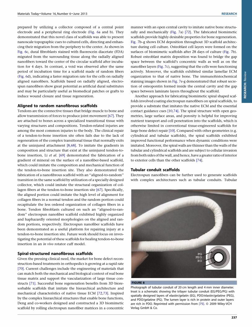
FIGURE 8
Photograph of tubular conduit of 20 cm length and 4 mm inner diameter.Inset is a schematic showing the trilayer tubular conduit (EG/PEG/PG) with
spatially designed layers of elastin/gelatin (EG), PDO/elastin/gelatine (PEG),
and PDO/gelatine (PG). The lumen layer is rich in protein and outer layers
are rich in PDO. Reprinted with permission from [75]. � 2009 Wiley-VCHVerlag GmbH & Co.
237
RESEARCH:Review
RESEARCH Materials Today � Volume 16, Number 6 � June 2013[(Figure_9)TD$FIG]
FIGURE 9
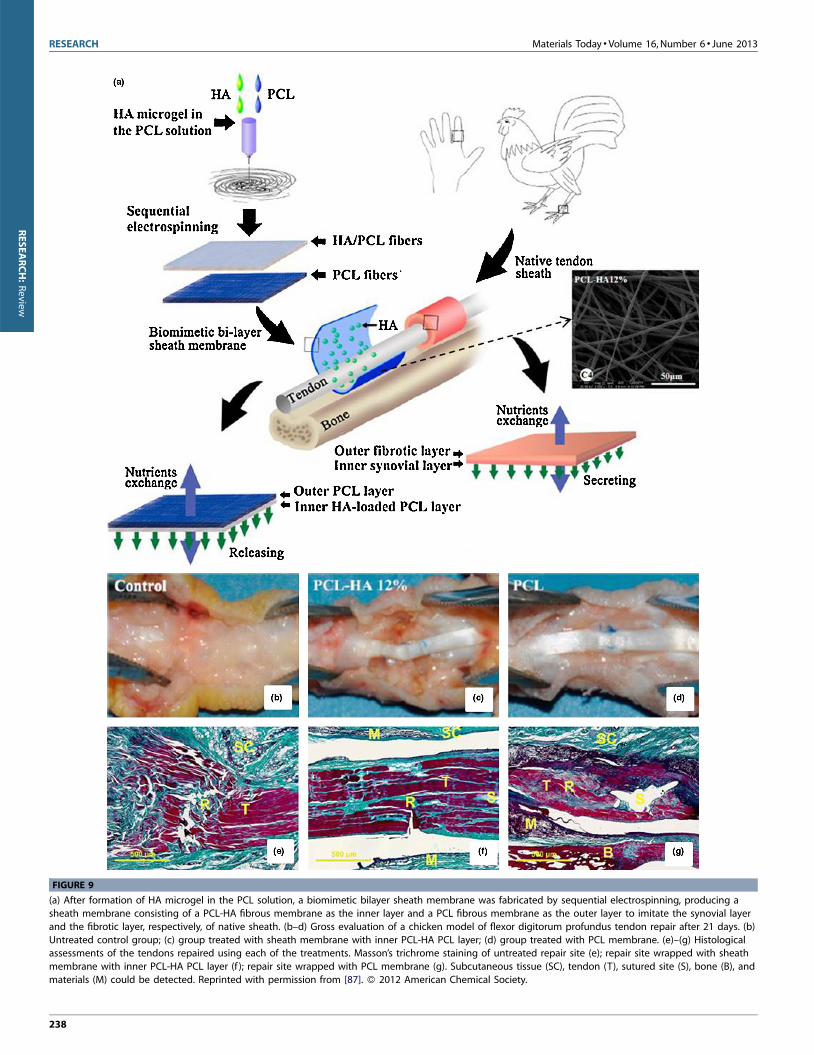
(a) After formation of HA microgel in the PCL solution, a biomimetic bilayer sheath membrane was fabricated by sequential electrospinning, producing asheath membrane consisting of a PCL-HA fibrous membrane as the inner layer and a PCL fibrous membrane as the outer layer to imitate the synovial layer
and the fibrotic layer, respectively, of native sheath. (b–d) Gross evaluation of a chicken model of flexor digitorum profundus tendon repair after 21 days. (b)
Untreated control group; (c) group treated with sheath membrane with inner PCL-HA PCL layer; (d) group treated with PCL membrane. (e)–(g) Histologicalassessments of the tendons repaired using each of the treatments. Masson’s trichrome staining of untreated repair site (e); repair site wrapped with sheath
membrane with inner PCL-HA PCL layer (f ); repair site wrapped with PCL membrane (g). Subcutaneous tissue (SC), tendon (T), sutured site (S), bone (B), and
materials (M) could be detected. Reprinted with permission from [87]. � 2012 American Chemical Society.
238
RESEARCH:Review
conduits comprised of electrospun fibers can be easily fabricated
by collecting nanofibers over a rotating rod of desired diameter
(<5 mm) and length (e.g. �15 cm length for coronary bypass). For
example, a trilayer tubular conduit of 20 cm length and 4 mm
inner diameter was fabricated by sequential electrospinning of
blends of polydioxanone (PDO) and proteins onto a small dia-
meter rod (4 mm), which imitates the complex matrix structure of
native arteries (Fig. 8) [75]. Apart from this one-step molding
process, a tubular conduit can also be prepared by rolling up
electrospun fibrous membranes and securing the edges with sol-
vent, glue, or heating [76]. This strategy allows fabrication of
multilayered conduits with aligned fibers in the inner layer and
random fibers in the outer layer, which could support better
nutrient transport and cell outgrowth without compromising
contact guidance [8].
One of the major applications of electrospun nanofibrous tub-
ular conduits is in vascular tissue regeneration. This is because
electrospun nanofibrous tubular conduits resemble the hollow
structures of vascular or neural tissues. Seamless, nonwoven, bior-
esorbable vascular prosthetics composed of submicron fibers were
fabricated using electrospinning [77], and electrospun collagen
and elastin fibers showed promise in vascular tissue engineering
[77]. While natural polymer grafts offer excellent cell-matrix inter-
actions, they often lack the mechanical properties of synthetic
polymers like PLLA and PGA. When used as a scaffold, these
natural polymers rapidly lose strength and dimensional stability,
due to gelation and rapid hydrolysis in culture media [75]. There-
fore, collagen and elastin-based substances alone are unlikely
candidates for vascular tissue engineering, especially under the
periodically loaded stress field typical of vascular structures [78].
Similarly, while synthetic polymer grafts offer excellent mechan-
ical properties and easily tailored degradation, they often lack the
bioactivity of natural polymers [77]. As such, there has been a great
need to create bioresorbable vascular prosthetics that incorporate
both the strength of synthetics and the bioactivity of natural
polymers. The use of bio-artificial blend nanofibers could be ideal
since they not only imitate the dimensions and compositions of
ECM, but also have good mechanical properties. Stitzel et al. [79]
fabricated tubular scaffolds of electrospun PLGA-collagen-elastin
ternary blend fibers, and achieved adequate mechanical strength
and elasticity and appropriate bioactivities. The electrospinning
process allows control of the grafts’ mechanical and bioactive
properties, which allows for the creation of more dynamic grafts
that can closely imitate the behavior and signaling of a native
artery [80].
Another application of electrospun nanofibrous tubular con-
duits is in nerve repair [76]. When direct suturing of two opposing
nerve stumps during surgery is not feasible, scaffolds are often used
to bridge the damaged nerve gap and to guide nerve regeneration
[81]. The scaffold used in nerve tissue engineering applications
requires optimal guidance effect, mechanical strength, and cellu-
lar compatibility [82]. Electrospun fibrous tubular conduits have
shown potential as scaffolds in nerve regeneration applications, as
their aligned fibers can provide guidance for axonal growth and
the fibrous structure imitates the nerve microenvironment [83]. It
has been reported that electrospun fibers could support oriented
neurite outgrowth and glial cell migration from dorsal root ganglia
explants [84]. In vivo studies indicated that nerve conduits with an
inner layer of aligned fibers led to improved peripheral nerve
regeneration [85]. In vitro investigation showed that, when the
filament size was in the subcellular size range, growth cones could
easily sense the energy differences of different outgrowth direc-
tions. Yao et al. [82] developed a fibrous PCL conduit with aligned
fibers on the interior surface via electrospinning and determined
the optimal fiber diameter in the subcellular size range for neurite
extension and directional growth. Neurite length on aligned
fibers, with fiber diameters of 3.7 � 0.5 mm and 5.9 � 0.9 mm,
was significantly longer than neurite length on randomly oriented
fibers. However, further research should include efforts to design
conduits with a suitable degradation profile and optimized fiber
organization for better guidance of regenerative axon growth [76].
Biomimetic sheath membraneThe membrane-shaped tendon sheath consists of an outer fibrotic
layer and an inner synovial layer. The fibrotic layer prevents
exogenous healing of the tendon as an effective biological barrier
while the synovial layer secretes synovial fluid (e.g. hyaluronic
acid (HA)) to enable tendon gliding [86]. In order to repair damage,
biological replication of the tendon sheath is necessary because it
allows the tendon to glide smoothly within the sheath. To repli-
cate the hierarchical architecture and complex biologic functions
of a native sheath, a biomimetic sheath should consist structurally
of an outer antiadhesion layer and an inner lubricant layer. Liu
et al. [87] fabricated a sheath membrane by sequential electrospin-
ning, producing a biomimetic bilayer sheath membrane consist-
ing of an HA-loaded PCL fibrous membrane as the inner layer and a
PCL fibrous membrane as the outer layer, which imitates a native
sheath (Fig. 9a). Large and severe peritendinous adhesion areas
were found at the repair site in the untreated control group (Fig. 9b
and e). In the tendons treated with biomimetic bilayer sheath
membrane, no formation of adhesions was observed between the
repaired tendons and the peritendinous tissues (Fig. 9c and f).
Although the adhesion area could be separated by blunt dissec-
tion, loose bundles of fibrous tissue were observed in PCL fibrous
membrane treatments (Fig. 9d and g). In vitro and in vivo results
showed that the outer PCL layer could reproduce the antiadhesive
role of the outer fibrotic layer while the inner HA loaded PCL layer
could imitate the biological function of HA secretion to promote
tendon healing and gliding, showing preliminary promise in
promoting tendon gliding and preventing adhesion.
Conclusions and outlookElectrospinning has emerged as an extremely promising method
for the preparation of tissue engineering scaffolds. This technique
offers advantages for the preparation of scaffolds in terms of
resembling the fibrillar structures of ECM, large surface areas, ease
of functionalization, and controllable mechanical properties, all of
which may lead to improvements in the ability to provide a true
biomimetic microenvironment to the developing tissue. Yet
important issues regarding its application in tissue engineering,
such as achievement of in-depth penetration of cells into scaffolds
and control of pore sizes, biomechanical properties, and solvent
toxicity still need further investigation [32]. Here, we reviewed the
utilization of the electrospinning approach to design and fabricate
nanofibrous materials that can be used as biomimetic scaffolds for
tissue engineering.
Materials Today � Volume 16, Number 6 � June 2013 RESEARCH
239
RESEARCH:Review
Despite recent advances toward the development of biomimetic
nanofibrous scaffolds for tissue engineering applications, several
challenges still remain. Generally, electrospun nanofibers were
collected as two-dimensional nonwoven, which limits their appli-
cations in 3D tissues. Therefore, one challenge that must be
addressed is the complexity of creating 3D porous scaffolds of a
clinically relevant 3D shape [88,89]. Fortunately, several attempts
have emerged that promise to bridge the gap, for instance, tubular
and spiral-structured nanofibrous scaffolds have been fabricated by
combining electrospinning with some additive manufacturing
technologies, which provide a potential solution to solve this
problem. It was recently reported that tissue-mimicking 3D porous
scaffolds could be developed by the alternate stacking of cells and
thin nanofiber substrate through a layer-by-layer approach [90]. It is
expected that the approach can be applied to 3D skin and bone
structures [33]. Additionally, it is crucial to develop a strategy
capable of producing fibers with a diameter identical to that of
native ECM fibers (a diameter less than 100 nm, preferably in the
range of 10–50 nm) while maintaining high porosity for cell infil-
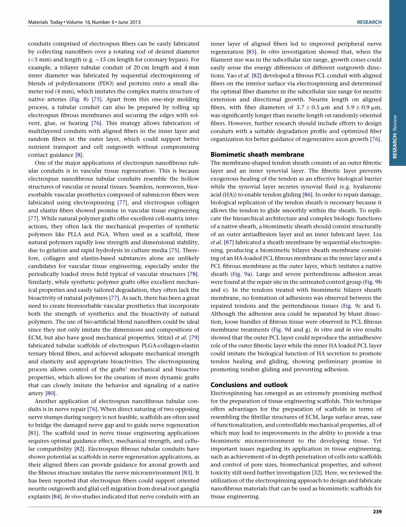
tration and migration [8]. The novel electro-spinning/netting (ESN)
technique [91–94] overcomes the bottleneck problem of electro-
spinning and offers a versatile method for generating spider-web-
like nano-nets with ultrafine fiber diameter (less than 50 nm) while
maintaining high porosity (Fig. 10), which make nano-nets optimal
candidates for the fabrication of tissue-engineering scaffolds.
Although many challenges remain, electrospinning exhibited
great potential in the fabrication of fibrous scaffolds with con-
trollable compositions and structures, enabling scientists from
various disciplines to design and generate novel scaffolds incor-
porating various biomimetic characteristics at genetic, molecular,
and nanometer scales [3]. We envision a continuous expansion of
the electrospinning approach in biomimetic scaffold design in the
coming decades, which will stimulate further research and
advances in the exciting field of tissue engineering.
AcknowledgementsWe acknowledge financial support from the West Virginia Higher
Education Policy Commission/Division of Science Research, NSF,
and AO Foundation (Project S-13-15L was supported by the AO
Foundation). We thank Suzanne Danley for proofreading.
References
1 T. Dvir, et al. Nat. Nanotechnol. 6 (2011) 13.
2 M.M. Stevens, J.H. George, Science 310 (2005) 1135.
3 P.X. Ma, Adv. Drug Deliv. Rev. 60 (2008) 184.
4 Y.P. Li, et al. Angew. Chem. Int. Ed. 51 (2012) 2864.
5 X.H. Zhang, et al. Adv. Drug Deliv. Rev. 61 (2009) 988.
6 J. Du, et al. Biomaterials 32 (2011) 5427.
7 J.A. Du, K.J. Yarema, Adv. Drug Deliv. Rev. 62 (2010) 671.
8 W. Liu, et al. Adv. Health. Mater. 1 (2012) 10.
9 J.M. Holzwarth, P.X. Ma, Biomaterials 32 (2011) 9622.
10 J.P. Wang, et al. J. Biomed. Mater. Res. Part A 93A (2010) 753.
11 S. Liao, et al. Biomed. Mater. 1 (2006) R45.
12 B.B. Jiang, et al. Biomacromolecules 11 (2010) 3630.
13 L.G. Griffith, G. Naughton, Science 295 (2002) 1009.
14 M. Goldberg, et al. J. Biomater. Sci. Polym. Ed. 18 (2007) 241.
15 Y.P. Li, et al. ACS Nano 6 (2012) 9485.
16 R. Vasita, D.S. Katti, Int. J. Nanomed. 1 (2006) 15.
17 P.X. Ma, R.Y. Zhang, J. Biomed. Mater. Res. 46 (1999) 60.
18 T.C. Holmes, et al. Proc. Natl. Acad. Sci. U. S. A. 97 (2000) 6728.
19 X.H. Liu, et al. Nat. Mater. 10 (2011) 398.
20 R.J. Wade, J.A. Burdick, Mater. Today 15 (2012) 454.
21 J.B. Matson, et al. Curr. Opin. Solid State Mater. Sci. 15 (2011) 225.
22 J.D. Hartgerink, et al. Proc. Natl. Acad. Sci. U. S. A. 99 (2002) 5133.
23 W.J. Li, et al. J. Biomed. Mater. Res. 60 (2002) 613.
24 N. Bhardwaj, S.C. Kundu, Biotechnol. Adv. 28 (2010) 325.
25 S.R. Bhattarai, et al. Biomaterials 25 (2004) 2595.
26 J. Shi, et al. ACS Appl. Mater. Interfaces 2 (2010) 1025.
27 H.R. Pant, et al. Colloid Surf. B: Biointerfaces 88 (2011) 587.
28 S. Ramakrishna, et al. Mater. Today 9 (2006) 40.
29 J. Liu, et al. Small 5 (2009) 536.
30 H. Fong, et al. Polymer 40 (1999) 4585.
31 D. Li, Y.N. Xia, Adv. Mater. 16 (2004) 1151.
32 S. Agarwal, et al. Adv. Mater. 21 (2009) 3343.
33 J.H. Jang, et al. Adv. Drug Deliv. Rev. 61 (2009) 1065.
34 Z.M. Huang, et al. Compos. Sci. Technol. 63 (2003) 2223.
35 M.M. Hohman, et al. Phys. Fluids 13 (2001) 2201.
36 A.L. Yarin, et al. J. Appl. Phys. 89 (2001) 3018.
37 M. Bognitzki, et al. Adv. Mater. 13 (2001) 70.
38 A. Greiner, J.H. Wendorff, Angew. Chem. Int. Ed. 46 (2007) 5670.
39 B.D. Ulery, et al. J. Polym. Sci. Pt. B: Polym. Phys. 49 (2011) 832.
40 B. Ding, et al. Mater. Today 13 (2010) 16.
41 X.F. Wang, et al. Nano Today 6 (2011) 510.
42 P. Roach, et al. Soft Matter 4 (2008) 224.
43 R. Chen, J.A. Hunt, J. Mater. Chem. 17 (2007) 3974.
44 J.Y. Lin, et al. Crit. Rev. Solid State Mater. Sci. 37 (2012) 94.
45 V.J. Reddy, et al. Wound Repair Regen. 21 (2013) 1.
46 J. Wang, X. Yu, Acta Biomater. 6 (2010) 3004.
47 T.B.L. Nguyen, B.T. Lee, J. Biomater. Appl. 27 (2012) 255.
48 C.Y. Huang, et al. Biomaterials 33 (2012) 1791.
49 M.M. Stevens, Mater. Today 11 (2008) 18.
50 M. Deng, et al. IEEE Trans. Nanobiosci. 11 (2012) 3.
51 T.G. Kim, et al. Adv. Funct. Mater. 22 (2012) 2446.
52 F. Yang, et al. Biomaterials 26 (2005) 2603.
53 J. Xie, et al. ACS Nano 4 (2010) 5027.
54 L.S. Wan, Z.K. Xu, J. Biomed. Mater. Res. A 89 (2009) 168.
55 D. Li, et al. Adv. Mater. 16 (2004) 361.
56 D. Yang, et al. Adv. Mater. 19 (2007) 3702.
57 J.A. Matthews, et al. Biomacromolecules 3 (2002) 232.
58 W.E. Teo, S. Ramakrishna, Nanotechnology 17 (2006) R89.
59 G.C. Engelmayr, et al. Nat. Mater. 7 (2008) 1003.
60 M. Chen, et al. Acta Biomater. 9 (2013) 5562.
61 S.Y. Chew, et al. Biomaterials 29 (2008) 653.
62 L. He, et al. Acta Biomater. 6 (2010) 2960.
63 M.V. Jose, et al. Acta Biomater. 5 (2009) 305.
64 Y.Z. Cai, et al. J. Biomed. Mater. Res. A 100 (2012) 1187.
65 J.P. Chen, C.H. Su, Acta Biomater. 7 (2011) 234.
66 Z.P. Zhang, et al. Adv. Drug Deliv. Rev. 64 (2012) 1129.
67 J.W. Xie, et al. Nanoscale 2 (2010) 923.
68 L.E. Richardson, et al. Trends Biotechnol. 25 (2007) 409.
RESEARCH Materials Today � Volume 16, Number 6 � June 2013
[(Figure_10)TD$FIG]
FIGURE 10
SEM image of nano-fiber/net fabricated by ESN technique comprising
common electrospun nanofibers and spider-web-like nano-nets. Reprinted
with permission from [93]. � 2010 IOP Publishing Ltd.
240
RESEARCH:Review
69 X.R. Li, et al. Nano Lett. 9 (2009) 2763.
70 B.B. Jiang, B.Y. Li, J. Biomed. Mater. Res. B 88B (2009) 332.
71 B.Y. Li, et al. Biomaterials 30 (2009) 2552.
72 M. Deng, et al. Adv. Funct. Mater. 21 (2011) 2641.
73 J.H. Lee, et al. Biomaterials 33 (2012) 999.
74 C.M. Valmikinathan, et al. Mater. Sci. Eng. C: Mater. Biol. Appl. 31 (2011) 22.
75 V. Thomas, et al. Biotechnol. Bioeng. 104 (2009) 1025.
76 J.W. Xie, et al. Nanoscale 2 (2010) 35.
77 S.A. Sell, G.L. Bowlin, J. Mater. Chem. 18 (2008) 260.
78 S.J. Lee, et al. J. Biomed. Mater. Res. A 83A (2007) 999.
79 J. Stitzel, et al. Biomaterials 27 (2006) 1088.
80 S. Agarwal, et al. Polymer 49 (2008) 5603.
81 C.A. Bashur, et al. Biomaterials 27 (2006) 5681.
82 L. Yao, et al. J. Biomed. Mater. Res. B 90B (2009) 483.
83 L.M.Y. Yu, et al. Mater. Today 11 (2008) 36.
84 E. Schnell, et al. Biomaterials 28 (2007) 3012.
85 S.Y. Chew, et al. Adv. Funct. Mater. 17 (2007) 1288.
86 P. Sharma, N. Maffulli, J. Bone Joint Surg. Am. 87A (2005) 187.
87 S. Liu, et al. Biomacromolecules 13 (2012) 3611.
88 J.M. Holzwarth, P.X. Ma, J. Mater. Chem. 21 (2011) 10243.
89 H.J. Wang, C.A. van Blitterswijk, Biomaterials 31 (2010) 4322.
90 X.C. Yang, et al. Tissue Eng. A 15 (2009) 945.
91 X.F. Wang, et al. Nanoscale 3 (2011) 911.
92 B. Ding, et al. J. Mater. Chem. 21 (2011) 12784.
93 X.F. Wang, et al. Nanotechnology 21 (2010) 055502.
94 N.A.M. Barakat, et al. Polymer 50 (2009) 4389.
95 X. Zhang, et al. J. Mater. Chem. 18 (2008) 621.
96 W. Barthlott, C. Neinhuis, Planta 202 (1997) 1.
97 L. Jiang, et al. Angew. Chem. Int. Ed. 43 (2004) 4338.
98 Y. Miyauchi, et al. Nanotechnology 17 (2006) 5151.
99 Z.G. Guo, W.M. Liu, Plant Sci. 172 (2007) 1103.
100 L. Feng, et al. Adv. Mater. 14 (2002) 1857.
101 D. Li, et al. Nano Lett. 3 (2003) 1167.
102 G.D. Yan, et al. Langmuir 27 (2011) 4285.
103 R.E. Grojean, et al. Appl. Optics 19 (1980) 339.
104 Y. Zhao, et al. J. Am. Chem. Soc. 129 (2007) 764.
Materials Today � Volume 16, Number 6 � June 2013 RESEARCH
241
RESEARCH:Review


![DOI: Biomimetic Collagen Nanofibrous · crystallization in purely inorganic systems can also yield so-called ‘‘biomorphs’’ that resemble those of biomater-ials.[38,39] In](https://img.pdfslide.net/doc/110x75/5fd1d7ff5d387f1be83480e0/doi-biomimetic-collagen-crystallization-in-purely-inorganic-systems-can-also-yield.jpg)