Embed Size (px)
Citation preview

Hannard et al., Sci. Robot. 6, eabf9710 (2021) 11 August 2021
S C I E N C E R O B O T I C S | R E S E A R C H A R T I C L E
1 of 9
B I O M I M E T I C S
Segmentations in fins enable large morphing amplitudes combined with high flexural stiffness for fish-inspired robotic materialsFlorent Hannard1,2, Mohammad Mirkhalaf1,3, Abtin Ameri1, Francois Barthelat1,4*
Fish fins do not contain muscles, yet fish can change their shape with high precision and speed to produce large and complex hydrodynamic forces—a combination of high morphing efficiency and high flexural stiffness that is rare in modern morphing and robotic materials. These “flexo-morphing” capabilities are rare in modern morphing and robotic materials. The thin rays that stiffen the fins and transmit actuation include mineral segments, a promi-nent feature whose mechanics and function are not fully understood. Here, we use mechanical modeling and me-chanical testing on 3D-printed ray models to show that the function of the segmentation is to provide combinations of high flexural stiffness and high morphing amplitude that are critical to the performance of the fins and would not be possible with rays made of a continuous material. Fish fin–inspired designs that combine very soft materials and very stiff segments can provide robotic materials with large morphing amplitudes and strong grasping forces.
INTRODUCTIONFish fins from Actinopterygii (ray-finned fish) “probably represent the most elaborate and refined adaption to efficient interaction with water that has ever evolved” (1). They do not contain muscles, yet fish can change the orientation and the shape of their fins to generate powerful hydrodynamic forces in three dimensions (Fig. 1A) (1, 2). Individual fish fins are composed of a few dozen slender bony rays connected by collagen fibrils and covered with skin (Fig. 1B). The rays have a diameter in the order of ~500 m with a tapered profile and an aspect ratio >100 (Fig. 1, C and D) (3, 4). Each ray is com-posed of two parallel mineralized layers called hemitrichs. The hemitrichs are fused at the end of the ray (5), while along the ray, they are connected by collagen fibrils embedded in a ground gel-like substance that also contains the cells and the vascular system necessary for growth and repair (“core” region; Fig. 1, B and E) (6). This construction is such that push/pull forces at the base generate shear deformations in the core region, which in turn induce flexural deformations along the entire length of the ray (Fig. 1B) (6–8). The forces needed to “morph” individual rays are small: A 1-mm deflec-tion on a typical ~50-mm-long ray only requires a pair of forces in the order of 0.01 mN (6). However, rays are also stiff under external transverse loads, which is critical to sustain large hydrodynamic forces without collapsing. A 1-mm flexural deflection requires a transverse force in the order of 1 mN (8)—100 times the base actuation force needed for the same deflection.
This combination of high flexural stiffness and high morphing efficiency is superior to state-of-the-art engineering morphing materials, which are either very compliant to achieve large shape changes (metamaterials, elastomers, and hydrogels) or very stiff but with large actuation forces for small changes in shape (piezo-actuated sandwich beams). This conflict of properties, illustrated in Fig. 1F,
prevents a wider application of engineered morphing materials in aerospace, robotics, and other smart structures. In particular, soft robotic grippers are good candidates for delicate grasping and soft manipulation of deformable, fragile, and even time-varying objects (9, 10) without the need for complex feedback systems (11–13). For example, a fish fin–inspired soft robotic material invented in 1997 by L. Kniese and patented by EvoLogics GmbH Berlin (14) can change its shape when loaded mechanically, which found a variety of applications. This design has been commercially available for soft grippers since 2016 [Festo’s FinGrippers (9)]. However, these fin ray–inspired fingers provide a relatively small grasping force com-pared with the gripper input force due to their low rigidity (9), which is typical of a general challenge in soft robotics: Softness enables dexterity, but stiffening is required to increase the forces transferred to the environment when necessary (15). Natural fish fins on the other hand combine the best of both worlds with high morphing efficiency and flexural stiffness, a performance made possible by a finely tuned synergy between the properties of the constituents and the structure of the rays. The morphology of fin rays, such as their thickness and length, influences their flexural stiffness and curva-ture (16, 17). A prominent feature of the hemitrichs is their segmen-tation into ~1-mm-long bony segments connected by collagenous joints that act as flexural hinges (18). This segmentation, prominent and universal in ray-finned fish, has been described in the past as a feature that decreases flexural stiffness of fin rays (19, 20), but its exact function is not known. Mechanical models have ignored seg-mentation and assumed homogenized properties for the hemitrichs (7, 8) [except for the Geerlink and Videler model (6)]. Segmentation could be a way to increase the compliance of the hemitrichs to achieve the flexibility required for morphing, yet there are other, more direct ways to control stiffness in homogeneous structures: partial but uniform mineralization as seen in teleost fish bones (21) or fish scales (22) or cartilaginous tissues as in shark fins (23, 24). Other possible functions for the segmentation of the hemitrichs may be related to growth and regeneration (25, 26), damage tolerance (27), or hydrodynamic performance (28). Here, we explored an alternative hypothesis: Segmentation is key to achieving the combination of high morphing efficiency and high flexural stiffness in fish fins.
1Department of Mechanical Engineering, McGill University, 817 Sherbrooke Street West, Montreal, QC H3A 2K6, Canada. 2Institute of Mechanics, Materials, and Civil Engineering, UCLouvain, Louvain-la-Neuve, Belgium. 3School of Aerospace, Me-chanical and Mechatronic Engineering, University of Sydney, NSW 2006, Australia. 4Department of Mechanical Engineering, University of Colorado, 427 UCB, 1111 Engineering Dr, Boulder, CO 80309, USA.*Corresponding author. Email: [email protected]
Copyright © 2021 The Authors, some rights reserved; exclusive licensee American Association for the Advancement of Science. No claim to original U.S. Government Works
at UN
IV O
F C
OLO
RA
DO
LIBR
AR
IES
on August 14, 2021
http://robotics.sciencemag.org/
Dow
nloaded from

Hannard et al., Sci. Robot. 6, eabf9710 (2021) 11 August 2021
S C I E N C E R O B O T I C S | R E S E A R C H A R T I C L E
2 of 9
RESULTSIndividual rays: Morphing and flexural stiffnessTo explore the hypothesis stated above, we started with a two- dimensional (2D) model for an individual ray (Fig. 2A) consisting of a compliant core (the collagenous fin membrane) sandwiched between two stiff beams (hemitrichs). The individual ray has a length L and a width w, and consists of a compliant collagenous core (thickness tc and shear modulus Gc; Fig. 2A) sandwiched between two stiff beams (hemitrichs) fused at the end of the ray. The hemi-trichs are assumed to be homogeneous for this first part of the model, with a modulus Eh, thickness th, cross-sectional area Ah, and second moment of inertia Ih. The neutral axes of each of the two hemitrichs are at a distance h apart (h = th + tc; Fig. 2A). For this study, we fo-cused on the effects of segmentation, and we excluded other mor-phological features such as the tapering toward the distal end of the ray and the 3D structure of the ray (see fig. S5). This simplification allows the analysis to show the effects of segmentation on the flexural stiffness and morphing response of the ray. The base of the ray may transmit push/pull actuation forces to the individual hemitrichs, which induce shear deformation in the core region and flexural de-formations of the ray. Considering the neutral axis of each individual hemitrich was a convenient way to capture the flexural component
of their deformation and stresses. As part of a multilayered system in flexure, the hemitrich also carried large compressive or tensile axial forces generated by the overall flexure of the ray (fig. S1).
Assuming small deformations and linear elasticity for the bony and core layers and combining equations from kinematics, deform-ation, and local stress equilibrium in the core and in the hemitrichs (see Supplementary Materials), the governing equation for the shearing displacement of the core u (as a function of the curvilinear distance s along the ray, where s = 0 is at the base of the ray) along the ray is
d 3 u ─ ds 3
= C 2 ─ h 2
du ─ ds with C 2 = 1 ─ 2 G c ─ E h h ─ t c [ 4wh ─ A h + wh 3 ─ I h ] (1)
Three critical features differentiate this model from existing me-chanical models on the morphing (6, 8) or flexural deformation (29) of individual rays: (i) In addition to flexural deformations, the hemitrichs may elongate or contract from axial stresses; (ii) the con-tributions from flexural deformations (term wh 3 _ I h ) and axial deforma-tions (term 4wh _ A h ) are completely decoupled; and (iii) the model does not explicitly specify how the flexural stiffness EhIh and the axial stiffness EhAh are generated. Our model therefore provides a general
Fig. 1. Key features in individual fin rays. (A) Fish can change the shape and effective surface of their fins from actuation by base muscles. (B) Cross section of a fin showing the bony rays and surrounding softer tissues [inspired from (4)]. (C) An individual ray from a fish fin harvested from Atlantic salmon (Salmo salar) can be “morphed” by applying push/pull forces manually. (D) Micro–computed tomography (micro-CT) scans of a caudal fin ray from Atlantic salmon in rest position and actuated position. The hemitrichs “glide” on one another from the base actuation, which induces flexural deformations. (E) Schematic of this mechanism. (F) Fish fins combine high morphing efficiency and high stiffness from external loads, two properties that are mutually exclusive in engineering morphing materials.
at UN
IV O
F C
OLO
RA
DO
LIBR
AR
IES
on August 14, 2021
http://robotics.sciencemag.org/
Dow
nloaded from

Hannard et al., Sci. Robot. 6, eabf9710 (2021) 11 August 2021
S C I E N C E R O B O T I C S | R E S E A R C H A R T I C L E
3 of 9
approach that offers many design options as to how to create and decouple these two stiffness terms.
The governing Eq. 1 accepts a general solution of the form
u(s) ─ h = A cosh ( C s ─ h ) + B sinh ( C s ─ h ) + D (2)
Constants A, B, and D must be determined from the type of loading, from boundary conditions, and from the end condition [in this report, we focused on the fused end where u(L) = 0]. In the “morphing problem” (Fig. 2B), a pair of forces F0 is applied at the base of the fin, which deforms the core region in shear and progressively translates into flexural deflections over part of or the entire length of the ray. We introduce a “morphing length” Lm that provides the characteristic length over which morphing takes place, which can be determined from the exact morphing solution (see section S1)
L m ─ L = tanh(CL / h) ─ CL / h (3)
If the core is too stiff and/or the ray is too slender (high CL/h), the flexural deformation is concentrated near the base of the ray, and the ray simply “hinges” at the base (Fig. 2B). In contrast, if CL/h is small, then shape morphing occurs along the entire length of the ray, which is the desired response. A natural way to achieve small CL/h is to use a core material that is much more compliant than the hemitrichs (Gc << Eh; Eq. 1), as seen in natural fish fins. Equation 1 can also be solved for the cantilever beam problem with a transverse end force P (Fig. 2C). Figure 2D shows an interesting example ob-tained by superposition, where the deflection from P is fully cancelled by applying a pair of actuation forces F0 at the base, effectively endowing the ray with an infinite stiffness.
These solutions were obtained within the assumptions of linear elasticity and small deformations. Large deformations and rotation may induce geometrical nonlinearities that we did not consider in our equations. To assess the limits of our linear model, we used finite element analysis (FEA) of rays of various dimensions and composi-tions (see section S2). These comparisons reveal that, for geometries and material properties representative of slender rays, our linear model is valid up to actuation displacements of at least u0/h ~ 0.25 and tip deflection from cantilever loading of at least d/h ~ 1. An important objective of the model was to explore how individual rays simultaneously achieve morphing efficiency (high morphing de-flection m for the least amount of force F0; Fig. 2B) and flexural stiffness (small deflection d for the highest force P; Fig. 2C). To this end, we computed a nondimensional morphing compliance Q* and a nondimensional flexural stiffness S*, which in the case where CL/h ≪ 1 and Ahh2 ≫ 4Ih [typical of lightweight sandwich materials (30); see section S1 for details] are written
⎧
⎪
⎨ ⎪
⎩
Q * = E h m w ─ F 0 ≈ wh 3 ─ 4 I h ( L ─ h )
2
S * = P ─ E h w d = 3 ─ 2 A h ─ wh ( h ─ L ) 3 (4)
Equation 4 defines two nondimensional performance indices Q* and S*, for morphing and stiffness, respectively. These performance indices include the effect of material properties (Eh and Gc) and ge-ometry (L, h, Ah, and Ih) in a condensed fashion that allows the visualization of the “flexo-morphing” performance of the ray on simple maps (presented below). Equation 4 shows that the morphing efficiency Q* is maximized for low flexural stiffness of the hemitrichs
Fig. 2. Mechanical model for individual rays. (A) A 2D model showing dimensions and properties. (B) Typical deflections from applying actuation forces on a ray with relatively stiff core (high CL/h), where deformation concentrates near the base, and on a ray with relatively compliant core (low CL/h), where morphing is uniform along the ray (reaction moments at the base are not shown). (C) Typical deflection from a transverse force P. (D) Example of a deformed ray subjected to an end force P, where the deflection is cancelled by applying actuation forces at the base, thus producing a ray with an infinite apparent flexural stiffness. at U
NIV
OF
CO
LOR
AD
O LIB
RA
RIE
S on A
ugust 14, 2021http://robotics.sciencem
ag.org/D
ownloaded from

Hannard et al., Sci. Robot. 6, eabf9710 (2021) 11 August 2021
S C I E N C E R O B O T I C S | R E S E A R C H A R T I C L E
4 of 9
Ih/wh3, while the flexural stiffness S* is maximized for high axial stiffness of the hemitrichs Ah/wh. This represents a design contra-diction, because for continuous hemitrichs, Ih and Ah are tied, and one cannot increase one without increasing the other. More specif-ically, Ih and Ah are tied through the size and geometry of the cross section by Ih = Ah
2, where is a nondimensional geometrical factor (for regular shapes with aspect ratio from 0.1 to 10, is between 0.01 and 1; Fig. 3A). To illustrate this point, we computed Q* and S* for a wide range of parameters (0.5 < tc/h < 0.9, 10−4 < Gc/Eh < 10−1) with square cross section for the hemitrichs and fixed L/h = 10. The results are displayed on the S*-Q* map on Fig. 3B. Ray designs that require low actuation forces for morphing (low Ah and Ih) deform easily from external loads; on the other hand, stiffer ray designs (high Ah and Ih) will require high forces to morph. This design con-traction is typical of the main limitation (Fig. 1F) of current engi-neering morphing materials (other geometries for the cross section lead to the same conclusions). The best combinations of S* and Q* (Pareto front) are obtained for a combination of thick core and thin hemitrichs (tc /h = 0.9), which is consistent with the construction of natural rays in fish.
Segmented hemitrichsWe hypothesized that segmented hemitrichs can produce combina-tions of Ah and Ih that are not possible with continuous hemitrichs, thereby expanding the flexo-morphing capability of the ray. There are several ways to create mechanical segmentations along a beam (for example, joints made of softer materials or mechanical articu-lations). For simplicity, we generated segments by constricting the hemitrichs at regular intervals (Fig. 4A). The key parameters for the segmentation are the relative segment length l/h, the relative hinge length d/l, and the relative hinge thickness = tj /th, where th = h-tc is the thickness of the individual hemitrichs. We now consider the effects of introducing segmentation on the axial and flexural stiff-ness. We first assumed that when the segmented beam is subjected to axial or flexural deformation, the axial and flexural deformations are uniform in the hinges and uniform in the thicker segments. The axial and flexural stiffness for the segmented beam are then written
⎧
⎪ ⎨
⎪
⎩ S a (seg) = 1 ─ (1 / − 1 ) d / l + 1 S a (cont)
S f
(seg) = 1 ─────────── (1 / 3 − 1 ) d / l + 1
S f (cont)
(5)
where
⎧
⎪ ⎨
⎪
⎩ S a (cont) = E h A h ─ L
S f
(cont) = 3 E h I h ─ L 3
(6)
are the axial stiffness and the flexural stiffness of a continuous beam, with Ah = wth and Ih = wth
3/12 for a rectangular cross section (with thickness th and width w). To validate these assumptions and Eq. 5, we performed finite element analysis (FEA) on segmented beams. The mesh was refined until the solution (e.g., actuation force and the deflection curves) did not change with further mesh refinement. Nor-malized axial stiffness and flexural stiffness (i.e., stiffness of segmented beam/stiffness for continuous beam) are plotted in Fig. 4B for differ-ent values of segmentation parameter but with hinge length kept constant (i.e., d/l = 0.3). The analytical models are in good agreement with the FE results. The axial stiffness is slightly overestimated with Eq. 4, especially for smaller values of parameter . This is likely due to an increase of the stress concentration with thinner hinges—an effect that the analytical model did not capture. We also verified this model with flexural experiments on 3D-printed beams (the 3D printing and testing procedure are described below). The experiments were in good agreement with the models (Fig. 4A).
A key feature of the segmentation is that the flexural stiffness re-duces at a much faster rate than the axial stiffness by making the hinges thinner (reducing ). This is due to the cubic power on the term in Eq. 5. As a result, it becomes possible to design segmented beams with a high equivalent axial stiffness (EhAh)eq and a low equivalent flexural stiff-ness (EhIh)eq, which is highly desirable to achieve high morphing com-pliance and high flexural stiffness simultaneously (Eq. 4). Another way to highlight this effect is to compute the effective cross-sectional area and the effective second moment of inertia for the segmented beam
Fig. 3. Limitation of continuous cross sections and implications on morphing/stiffness combinations. (A) For continuous hemitrichs, the cross section Ah and the second moment of inertia Ih are tied by a relationship of the form Ih = Ah
2 with 0.01 < < 1 for common geometries. (B) Because of this constraint, morphing efficiency Q* and flexural stiffness S* are mutually exclusive (“Flexo-morphing” map obtained from the mechanical model over a wide range of parameters).
at UN
IV O
F C
OLO
RA
DO
LIBR
AR
IES
on August 14, 2021
http://robotics.sciencemag.org/
Dow
nloaded from
Hannard et al., Sci. Robot. 6, eabf9710 (2021) 11 August 2021
S C I E N C E R O B O T I C S | R E S E A R C H A R T I C L E
5 of 9
Fig. 4. Segmented hemitrichs. (A) Key dimensions: Segmentation is introduced by constricting the hemitrichs at regular intervals. (B) Axial stiffness and flexural stiffness as functions of the relative thickness of the hinge and fixed hinge length d/l = 0.3. The predictions from Eq. 6 are shown together with predictions from finite elements and experiments on 3D-printed segmented beams. Both axial and flexural stiffness decrease when the thickness of the hinge is decreased, but—and this is key—they do so at different rates. (C) (Ih)eq-(Ah)eq map for beams with a square cross section, showing how segmentation allows for combinations of axial stiffness and flexural stiffness that are not accessible with continuous designs.
Fig. 5. Effects of segmentation. (A) Q*-S* map for continuous and segmented designs, with material properties kept constant for hemitrichs and core. (B) Examples of improvements for fixed ray flexural stiffness, for fixed morphing efficiency, and for simultaneous improvements. (C) Q*-S* map for continuous and segmented designs, with material properties free. This additional degree of freedom in the design further enhances segmented designs. (D) Examples of improvements obtained from (C).
at UN
IV O
F C
OLO
RA
DO
LIBR
AR
IES
on August 14, 2021
http://robotics.sciencemag.org/
Dow
nloaded from
Hannard et al., Sci. Robot. 6, eabf9710 (2021) 11 August 2021
S C I E N C E R O B O T I C S | R E S E A R C H A R T I C L E
6 of 9
( A h ) eq = A h ─ (1 / − 1 ) d / l + 1
( I h ) eq = I h ───────────
(1 / 3 − 1 ) d / l + 1 (7)
Figure 4C shows a map of (Ih)eq-(Ah)eq for a continuous beam of square cross section and for segmented beams with the same thick-ness. The segmented design opens access to regions of the maps that maximize flexo-morphing performance (near the lower right cor-ner), forbidden for continuous designs (Fig. 3A). To assess the im-pact of segmentation on the performance of the ray, we considered designs with L/h = 10 and fixed material properties Gc /Eh = 10−3. Figure 5A shows that segmentation with d/l = 0.2 and 0.1 < < 0.9 leads to substantially higher combinations of flexural stiffness and morphing efficiency (red region) that are not accessible with rays based on continuous hemitrichs (black line). Figure 5B shows ex-amples of designs improved by segmentation. The figure highlights how the simple, continuous design a can be improved by segmentation (i) to increase the morphing compliance while maintaining flexural stiffness (design b), (ii) to increase flexural stiffness while maintaining morphing compliance (design c), or (iii) to increase both (design d). Figure 5 (A and B) shows that for the case where the material proper-ties of the core and hemitrichs are fixed (Gc/Eh = 10−3), segment-ation improves S* and Q* by a factor of 1.5 to 3.7. Opening up the design space and considering the properties for the core and
hemitrichs that can be optimized within the range 10−4 < Gc/Eh < 10−1 (Fig. 5, C and D) lead to even greater improvements when segment-ation is introduced: S* and Q* increase by a factor of 2.5 to 11.5.
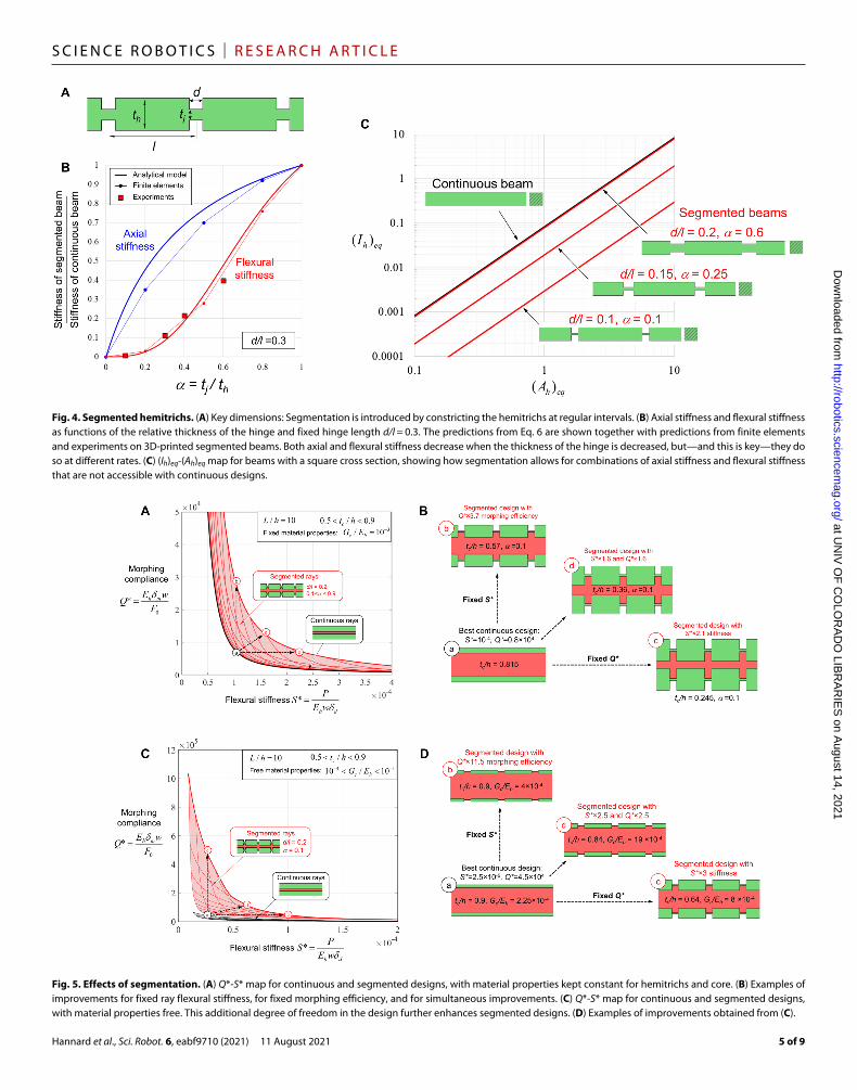
3D printing and testingWe verified the effects of segmentation using 3D printing and min-iaturized mechanical testing (details in Materials and Methods). All 3D-printed rays fabricated and tested in this study had the same length (L = 30 mm) and the same width (w = 3 mm), but the height, thickness, and segmentation geometry were varied to achieve dif-ferent combinations of flexural stiffness and morphing properties. For the continuous designs, we varied the thickness of the hemi-trichs th and the effective thickness of the ray h (Fig. 6B) to achieve a wide range of mechanical responses and morphing length Lm/L in the range from 0.2 to 0.6 (Eq. 6). For the segmented cases, we fixed d/l = 0.35 and varied from 0.15 to 0.6 (Fig. 6B), which produced morphing lengths Lm/L in the range 0.8 to 0.9 (higher than for the continuous case). For each 3D-printed ray, we performed (i) a flex-ural test (Fig. 6C), where a transverse displacement was imposed at the end of the ray while both sides of the base were clamped, and (ii) an actuation test (Fig. 6D), where an axial displacement was imposed on one side of the base, while the other was clamped (details in Materials and Methods).
Figure 7A shows all the experimental results on an S-Q map. The continuous rays produced different combinations of S and Q, which
Fig. 6. Fabrication and testing of 3D-printed rays. (A) Fabrication steps: 3D printing, infiltration with silicone, and release from pillars. (B) Continuous and segmented design for the 3D-printed rays. (C) A typical response from a cantilever deflection test. (D) A typical response from a morphing test. For all tests, we stayed in the linear regime.
at UN
IV O
F C
OLO
RA
DO
LIBR
AR
IES
on August 14, 2021
http://robotics.sciencemag.org/
Dow
nloaded from
Hannard et al., Sci. Robot. 6, eabf9710 (2021) 11 August 2021
S C I E N C E R O B O T I C S | R E S E A R C H A R T I C L E
7 of 9
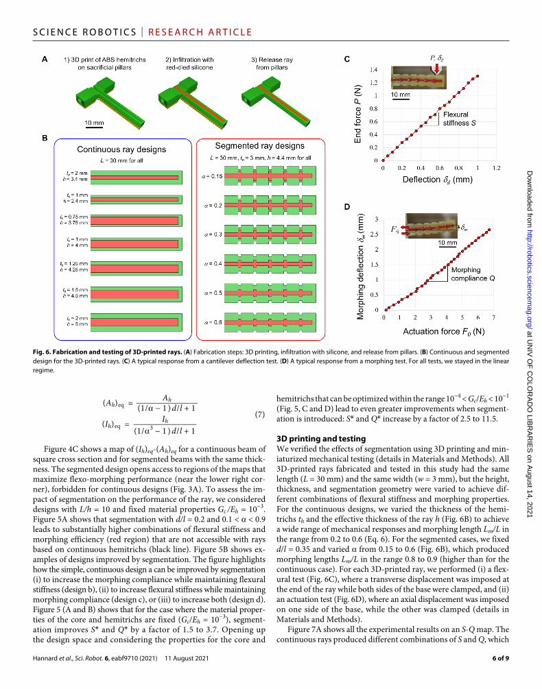
all fell on the trend predicted by our model. Designs with thicker rays (large h and large th) were the stiffest (high S), but they also required higher forces to morph (low Q). In contrast, thinner rays (low h and th) were much easier to morph (high Q) but also had low flexural stiffness S. Figure 7A also shows that the 3D-printed de-signs with segmented rays produced substantially higher combina-tions of S and Q, greatly expanding flexo-morphing performance of this morphing structure. For example, consider the continuous ray design a on Fig. 7 (A and B). Design a is relatively stiff in flexion because of its thick hemitrichs, but it also has a low morphing com-pliance. Enriching this design with segmentation can be done while maintaining the same high flexural stiffness, which leads to design c. Design c has thicker hemitrichs overall, but its morphing compli-ance Q is about four times higher than design a (that is, the force required to achieve the same morphing deformation is four times smaller, as shown in Fig. 7C). Alternately, one can consider design b, a continuous design that is “easy” to morph but that has a low flexural stiffness because of thin hemitrichs. Enriching design b with seg-mentation can be done by maintaining the same morphing compli-ance, leading to design c, which is about four times stiffer in flexion
compared with design b. Furthermore, we note that the agreement between our models and the experiments is good, which suggests that these models can be used to design and optimize ray-like morphing robotic materials.
Application to natural finsLast, we applied our models using typi-cal dimensions and properties of natural fish fins, to estimate how much stiffness and morphing compliance is gained by segmentation. We used dimensions that were estimated from micro–computed tomography images of individual rays (Fig. 8A) and with material properties represent ative of the hemitrich (10−1 < Eh < 10 GPa) and representative of the softer collagenous core material (10−3 < Gc < 10−1 MPa) (8). Figure 8B shows that segmentation leads to much higher combinations of flexural stiffness S and morphing efficiency Q compared with hypothetical continuous fin rays with the same dimensions. In addition, the values predicted by our model for seg-mented rays are within the range of experimental data for flexural stiffness [S ~ 10−3 N/mm; (8)] and morphing compliance [Q ~ 105 mm/N; (6)].
DISCUSSIONFish fins are useful mechanical systems and a rich source of inspiration for new designs in underwater propulsion (31), morphing robotic elements with high grasping forces (32), medical devices (33), or morphing flight surfaces that
can carry large aerodynamic forces for aerospace applications (34). The models and experiments on 3D- printed rays presented here show that segmentation of individual hemitrichs leads to combinations of high morphing efficiency and high flexural stiffness of the rays (high “flexo-morphing” capability) that are not accessible with continuous designs. Segmented designs therefore enable large amplitude with high grasping force, combined with tunable stiffness and capacity to adapt to the grasping of complex objects. An interesting question is the effect of the length of the individual segments. Variation in flexural stiffness of natural fin rays has been associated with different segmentation pat-terns (19, 20). For example, fin rays are stiffer for longer segments rel-ative to the total length of the fin ray (17). Fish fins that seem to play similar functional roles, such as the pectoral and caudal fins of acti-nopterygian fishes, have fin rays with similar morphology and flexural stiffness (19). These observations suggest that the relative length of these segments is governed by specific functional requirements (19), which we strongly suspect can be explained by mechanics (35).
Our models also established additional critical rules for op-timal flexural stiffness/morphing combinations: two to three orders of magnitude in stiffness contrast between the core and the
Fig. 7. Mechanical testing of continuous and segmented 3D-printed rays. (A) Experimental S-Q map (flexural stiffness. morphing compliance map) for continuous and segmented designs. The segmented designs reach combi-nations of high stiffness and high morphing that are not accessible with continuous designs. Model predictions are also shown. Error bars indicate the worst-case total error associated with the resolution of the load cell and the im-ages. (B) Three of the designs that were fabricated and tested. (C) Zoomed- in version of the S-Q map that shows, using designs a, b, and c as examples, how segmentation can increase both flexural stiffness and morphing compli-ance. (D) Flexural tests that illustrate that, while morphing compliance is greatly increased from designs a to c, high flexural stiffness is maintained. Flexural stiffness can be improved substantially from design b to c while maintaining the same high morphing compliance.
at UN
IV O
F C
OLO
RA
DO
LIBR
AR
IES
on August 14, 2021
http://robotics.sciencemag.org/
Dow
nloaded from

Hannard et al., Sci. Robot. 6, eabf9710 (2021) 11 August 2021
S C I E N C E R O B O T I C S | R E S E A R C H A R T I C L E
8 of 9
bony hemitrichs and thin hemitrichs relative to the core thickness. Both of these features are observed in natural fish fins. Natural evo-lution has therefore produced an elegant solution that allows fish fins to carry large hydrodynamic forces without collapsing and allows the fish to morph its fins with minimal muscular effort.
The theoretical model and 3D-printed models presented here are essentially two-dimensional and streamlined in terms of geometry and materials properties in order to focus on the effects of segment-ation. Natural rays however display many more morphological fea-tures that could also be incorporated in the design of bioinspired morphing elements. For example, the flexo-morphing capability could be further improved by tapering of the individual rays (3, 8). Indeed, Alben and McGee (29) already showed that tapered fin add stiffness under a distributed transverse load (such as that due to fluid pressure forces), whereas tapering of the ray was shown to be a simple way to increase its morphing length (6). On the other hand, designs with uniform thickness maintain high stiffness all the way to the tip, which may be more useful for configurations such as grasping, where the collapse of the tip from localized end forces must be prevented. The effects of the full 3D architecture of the ray and the crescent shape of the bony segments (fig. S5) could also be con-sidered in future models because they already have been shown to contribute to the flexibility of the fin ray (20). Of interest are the three-dimensional morphing response, stiffness, and stability of the rays (isolated or as part of an entire fin) subjected to complex three- dimensional hydrodynamic forces. In addition, the length of the segment decreases toward the end of the ray (19, 26), possibly creating a gradient in flexural and morphing properties that can improve the overall flexo-morphing capability of the ray. In this report, we also restricted our models and experiments to the linear range of struc-tural response. Natural fin rays undergo large deflections and are made of collagenous materials that undergo large strains (shear strain >100% in the core) with pronounced nonlinearities in material re-sponse. Geometrical and material nonlinearities certainly contribute to the performance of the fins, and their effects would deserve further attention (36). We expect that the benefits of segment ation should
carry over from the linear regimes to the nonlinear regimes, but ad-ditional modeling and experiments would be needed to confirm this.
The 3D-printed rays fabricated and tested here were mainly used to prove that segmentation is a simple but efficient way to achieve combinations of high flexural stiffness and high morphing amplitude, which is important for soft robotics applications. These 3D-printed models can, however, also serve as a proof of concept for segmented robotic grabbers. Future work could further expand the function-ality of these morphing devices by incorporating vacuum-actuated suckers (10), pads with electroadhesion functionality (37) to manu-facture a fin ray–inspired gripper, the coactivation of multiple ac-tuators to produce 3D trajectories (38), or stiffness gradients to minimize stress concentrations and delay failures at the interfaces between stiff and soft elements (39). Future studies should also in-clude experiments and modeling on natural rays, which present special challenges—including effects of hydration, rate dependence, complex material responses, variations in structure, and mechani-cal responses across species, across specimens of the same species, and also across different fins on the same specimen.
MATERIALS AND METHODS3D printing of synthetic raysThe hemitrichs were first printed on a high-resolution direct light projector (DLP) 3D printer (Micro HiRes, EnvisionTEC GmbH, Germany) on sacrificial pillars (Fig. 6A). The DLP printing method allows for high structural resolution, and the parts fabricated are fully dense and perfectly isotropic, so that direct quantitative comparison can be made between models and experiments on the 3D-printed parts. We verified experimentally that the as-printed acrylonitrile butadiene styrene (ABS) photopolymer used for the hemitrichs was isotropic, with a measured elastic modulus Eh = 1.5 GPa. The interstice between the hemitrichs was then filled with silicone mixed with a red dye for easier visualization. The measured shear modulus of the fully cured silicone was Gc = 0.55 MPa. Once the silicone was fully cured, the ray was carefully released by severing the sacrificial pillars.
Fig. 8. Effect of segmentation on a natural fin ray from Atlantic salmon (Salmo salar) estimated using our model. (A) Micro-CT reconstructed images of a ray taken from the caudal fin. The main geometrical parameters estimated from this image are shown. (B) Estimated S-Q map for the natural ray, which has segmented designs. The flexomorphing capability of the natural ray is much higher than a ray with the same dimensions and materials but made of continuous hemitrichs.
at UN
IV O
F C
OLO
RA
DO
LIBR
AR
IES
on August 14, 2021
http://robotics.sciencemag.org/
Dow
nloaded from

Hannard et al., Sci. Robot. 6, eabf9710 (2021) 11 August 2021
S C I E N C E R O B O T I C S | R E S E A R C H A R T I C L E
9 of 9
Mechanical testing of synthetic raysThe tests were performed using motorized micromanipulators (Sutter Instrument, CA, USA) (40) at rates in the order of 0.1 mm/s for all tests. This “quasi-static” rate was chosen to minimize viscoelastic and inertial effects and to allow for high-resolution image capture at regular intervals. Forces were measured using miniature resistive load cells [1-kg capacity, (41)], and the displacements were obtained from optical images. The slope from the flexural tests was used as a measure of flexural stiffness S, and the slope from the morphing tests served as a measure of the morphing compliance Q (Fig. 6, C and D). We chose a range of displacement and loads that ensured linear re-sponses and no damage to the rays; i.e., the deflection imposed within the linear limits was established from the FEA models (see section S2), loading and unloading paths were identical, and the measured force-deflection responses were linear.
SUPPLEMENTARY MATERIALSrobotics.sciencemag.org/cgi/content/full/6/57/eabf9710/DC1Sections S1 to S3Figs. S1 to S4Movies S1 to S3
REFERENCES AND NOTES 1. J. J. Videler, Fish Swimming (Springer Netherlands, 1993). 2. G. V. Lauder, Fish locomotion: Recent advances and new directions. Annu. Rev. Mar. Sci. 7,
521–545 (2015). 3. B. R. Aiello, A. R. Hardy, C. Cherian, A. M. Olsen, C. P. Orsbon, M. E. Hale, M. W. Westneat, A
comparison of pectoral fin ray morphology and its impact on fin ray flexural stiffness in labriform swimmers. J. Morphol. 279, 1031–1044 (2018).
4. J. Becerra, G. S. Montes, S. R. R. Bexiga, L. C. U. Junqueira, Structure of the tail fin in teleosts. Cell Tissue Res. 230, 127–137 (1983).
5. H. J. Haas, Studies on mechanisms of joint and bone formation in the skeleton rays of fish fins. Dev. Biol. 5, 1–34 (1962).
6. P. J. Geerlink, J. J. Videler, The relation between structure and bending properties of teleost fin rays. Neth. J. Zool. 37, 59–80 (1986).
7. C. W. McCutchen, The trout tail fin: A self-cambering hydrofoil. J. Biomech. 3, 271–281 (1970). 8. S. Alben, P. G. Madden, G. V. Lauder, The mechanics of active fin-shape control
in ray-finned fishes. J. R. Soc. Interface 4, 243–256 (2007). 9. X. Shan, L. Birglen, Modeling and analysis of soft robotic fingers using the fin ray effect.
Int. J. Robot. Res. 39, 1686–1705 (2020). 10. Z. Xie, A. G. Domel, N. An, C. Green, Z. Gong, T. Wang, E. M. Knubben, J. C. Weaver,
K. Bertoldi, L. Wen, Octopus arm-inspired tapered soft actuators with suckers for improved grasping. Soft Robot. 7, 639–648 (2020).
11. J. Shintake, V. Cacucciolo, D. Floreano, H. Shea, Soft robotic grippers. Adv. Mater. 30, 1707035 (2018).
12. N. Kellaris, V. Gopaluni Venkata, G. M. Smith, S. K. Mitchell, C. Keplinger, Peano-HASEL actuators: Muscle-mimetic, electrohydraulic transducers that linearly contract on activation. Sci. Robot. 3, eaar3276 (2018).
13. A. Rafsanjani, K. Bertoldi, A. R. Studart, Programming soft robots with flexible mechanical metamaterials. Sci. Robot. 4, eaav7874 (2019).
14. L. Kniese, Load carrying element with flexible outer skin. European Patent Office EP1040999A2 (1999).
15. M. Manti, V. Cacucciolo, M. Cianchetti, Stiffening in soft robotics: A review of the state of the art. IEEE Robot. Autom. Mag. 23, 93–106 (2016).
16. N. K. Taft, G. V. Lauder, P. G. A. Madden, Functional regionalization of the pectoral fin of the benthic longhorn sculpin during station holding and swimming. J. Zool. 276, 159–167 (2008).
17. N. K. Taft, B. N. Taft, Functional implications of morphological specializations among the pectoral fin rays of the benthic longhorn sculpin. J. Exp. Biol. 215, 2703–2710 (2012).
18. T. A. Stewart, J. B. Lemberg, N. K. Taft, I. Yoo, E. B. Daeschler, N. H. Shubin, Fin ray patterns at the fin-to-limb transition. Proc. Natl. Acad. Sci. U.S.A. 117, 1612–1620 (2020).
19. N. K. Taft, B. N. Taft, H. Henck, T. Mehner, Variation in flexural stiffness of the lepidotrichia within and among the soft fins of yellow perch under different preservation techniques. J. Morphol. 279, 1045–1057 (2018).
20. N. K. Taft, Functional implications of variation in pectoral fin ray morphology between fishes with different patterns of pectoral fin use. J. Morphol. 272, 1144–1152 (2011).
21. J. D. Currey, Mechanical properties and adaptations of some less familiar bony tissues. J. Mech. Behav. Biomed. Mater. 3, 357–372 (2010).
22. D. Zhu, C. F. Ortega, R. Motamedi, L. Szewciw, F. Vernerey, F. Barthelat, Structure and mechanical performance of a "modern" fish scale. Adv. Eng. Mater. 14, B185–B194 (2012).
23. A. M. R. Maia, C. A. D. Wilga, G. V. Lauder, Biomechanics of locomotion in sharks, rays, and chimaeras, in Biology of Sharks and Their Relatives, 2nd Edition, J. C. Carrier, J. A. Musick, M. R. Heithaus, Eds. (CRC Press-Taylor & Francis Group, 2012), pp. 125–151.
24. R. Seidel, A. K. Jayasankar, M. N. Dean, The multiscale architecture of tessellated cartilage and its relation to function. J. Fish Biol. 98, 942–955 (2020).
25. C. Pfefferli, A. Jaźwińska, The art of fin regeneration in zebrafish. Regeneration 2, 72–83 (2015).
26. A.-G. Rolland-Lagan, M. Paquette, V. Tweedle, M.-A. Akimenko, Morphogen-based simulation model of ray growth and joint patterning during fin development and regeneration. Development 139, 1188–1197 (2012).
27. C. J. Schulte, C. Allen, S. J. England, J. L. Juárez-Morales, K. E. Lewis, Evx1 is required for joint formation in zebrafish fin dermoskeleton. Dev. Dyn. 240, 1240–1248 (2011).
28. B. E. Flammang, S. Alben, P. G. A. Madden, G. V. Lauder, Functional morphology of the fin rays of teleost fishes. J. Morphol. 274, 1044–1059 (2013).
29. S. Alben, R. L. McGee, Optimizing a fin ray for stiffness. J. Mech. Phys. Solids 58, 656–664 (2010).
30. H. G. Allen, Sandwich beams, in Analysis and Design of Structural Sandwich Panels, H. G. Allen, Ed. (The Commonwealth and International Library: Structures and Solid Body Mechanics Division, Pergamon, 1969), pp. 8–47.
31. C. J. Esposito, J. L. Tangorra, B. E. Flammang, G. V. Lauder, A robotic fish caudal fin: Effects of stiffness and motor program on locomotor performance. J. Exp. Biol. 215, 56–67 (2012).
32. S. Kim, C. Laschi, B. Trimmer, Soft robotics: A bioinspired evolution in robotics. Trends Biotechnol. 31, 287–294 (2013).
33. L. Blanc, A. Delchambre, P. Lambert, Flexible medical devices: Review of controllable stiffness solutions. Actuators 6, 23 (2017).
34. S. Barbarino, O. Bilgen, R. M. Ajaj, M. I. Friswell, D. J. Inman, A review of morphing aircraft. J. Intell. Mater. Syst. Struct. 22, 823–877 (2011).
35. T. N. Sullivan, M. A. Meyers, E. Arzt, Scaling of bird wings and feathers for efficient flight. Sci. Adv. 5, eaat4269 (2019).
36. K. Nguyen, N. Yu, M. M. Bandi, M. Venkadesan, S. Mandre, Curvature-induced stiffening of a fish fin. J. R. Soc. Interface 14, 20170247 (2017).
37. R. Chen, R. Song, Z. Zhang, L. Bai, F. Liu, P. Jiang, D. Sindersberger, G. J. Monkman, J. Guo, Bio-inspired shape-adaptive soft robotic grippers augmented with electroadhesion functionality. Soft Robot. 6, 701–712 (2019).
38. M. A. Robertson, J. Paik, New soft robots really suck: Vacuum-powered systems empower diverse capabilities. Sci. Robot. 2, eaan6357 (2017).
39. N. W. Bartlett, M. T. Tolley, J. T. B. Overvelde, J. C. Weaver, B. Mosadegh, K. Bertoldi, G. M. Whitesides, R. J. Wood, A 3D-printed, functionally graded soft robot powered by combustion. Science 349, 161–165 (2015).
40. S. Instrument, Solo Micromanipulator (2019); www.sutter.com/MICROMANIPULATION/solo_frame.html [accessed 7 April 2020].
41. L. Sensor, REB7 Universal Sub Miniature Load Cell (2019); www.loadstarsensors.com/reb7-universal-sub-miniature-load-cell.html [accessed 15 June 2020].
Acknowledgments: We thank Y. Xiao (Centre for Bone and Periodontal Research) for assistance with the micro-CT scans. Funding: This work was supported by a Discovery Grant from the Natural Sciences and Engineering Research Council of Canada. M.M. was partially supported by a McGill Engineering Doctoral Award from the Faculty of Engineering. A.A. was supported by a Summer Undergraduate Research in Engineering Award from the Faculty of Engineering at McGill. Author contributions: F.B. and M.M. contributed to the initiating idea. F.B., M.M., and F.H. contributed to the mechanical models. F.H., M.M., and A.A. designed the fabrication protocol and contributed to the fabrication of 3D-printed ray models. F.H. and F.B. designed the custom testing setup. F.H., M.M., and A.A. performed miniaturized mechanical testing. F.B., F.H., and M.M. analyzed the experimental results, prepared the figures, and wrote the manuscript. All authors commented on the manuscript. Competing interests: The authors declare that they have no competing interests. Data and materials availability: All data needed to evaluate the conclusions in the paper are present in the main manuscript and/or the Supplementary Materials.
Submitted 9 December 2020Accepted 19 July 2021Published 11 August 202110.1126/scirobotics.abf9710
Citation: F. Hannard, M. Mirkhalaf, A. Ameri, F. Barthelat, Segmentations in fins enable large morphing amplitudes combined with high flexural stiffness for fish-inspired robotic materials. Sci. Robot. 6, eabf9710 (2021).
at UN
IV O
F C
OLO
RA
DO
LIBR
AR
IES
on August 14, 2021
http://robotics.sciencemag.org/
Dow
nloaded from


![Biomimetics Report Final Version[1]](https://img.pdfslide.net/doc/110x75/5556b28dd8b42a9c798b546e/biomimetics-report-final-version1.jpg)