Embed Size (px)
Citation preview
1
Wing
Airfoil selection
• Aerodynamic characteristics (Kmax, CLmax, stall characteristics)
• Structural reasons;

2
Airfoil geometry
Airfoil geometry
Leading edge
Trailing edge
Chord
Camber line
Maximum thickness
Maximum camberMaximum
thickness position Maximum camber
position

3
Angle of attack definition
V∞
AoA
Stall
AoA=0°
AoA=10°
AoA=15°
AoA=20°
Separation point
4
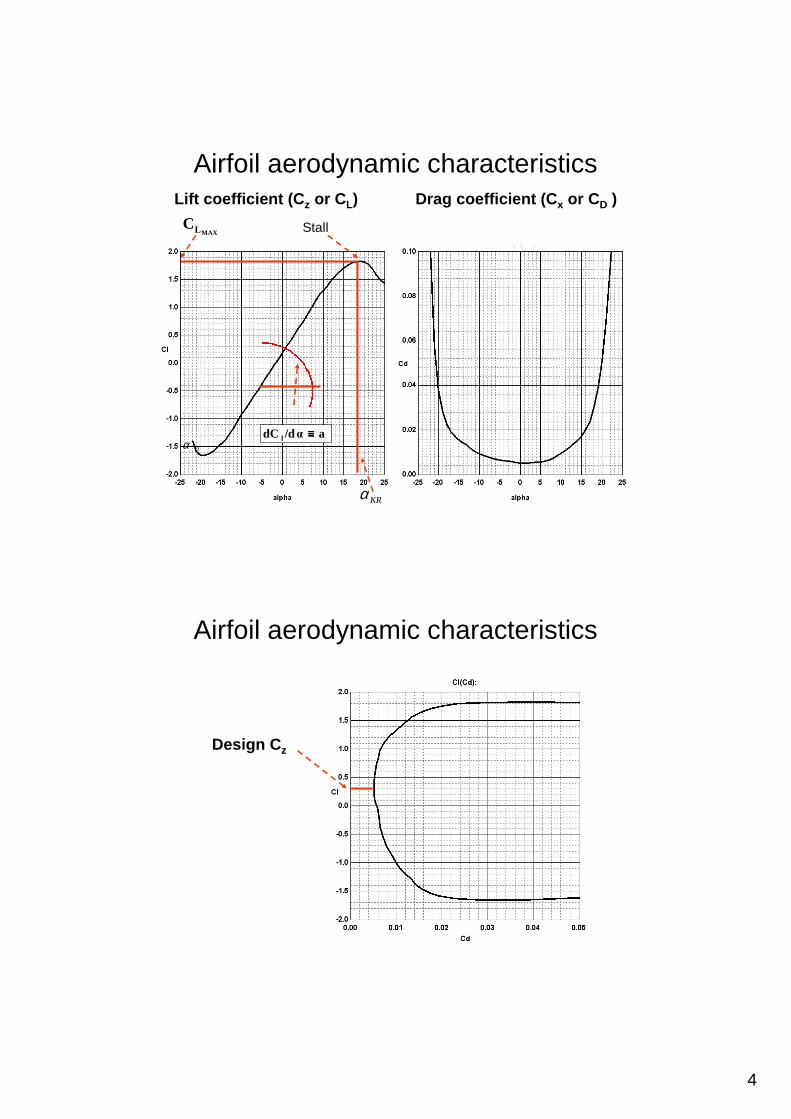
Airfoil aerodynamic characteristics
a/dαdC l ≡≡≡≡0α
KRα
MAXLC
Drag coefficient (C x or CD )Lift coefficient (C z or CL)
Stall
Airfoil aerodynamic characteristics
Design C z

5
Airfoil aerodynamic characteristicsPower factor(Cz
3 / Cx2 lub C z
1,5 /Cx)Gliding ratio (C z / Cx)
Airfoil aerodynamic characteristicsPitching moment coefficient C m
Derivative dCm/dCzis an indicator of stability.
It is negative for stable aeroplanesand positive for unstable aeroplanes.

6
Maximum thickness – t/c
Maximum thickness - t
Chord - c
Effect of airfoil thickness on lift coefficient
6%
8%
10%
12%
14%
16%
18%
20%

7
Effect of airfoil thickness on lift coefficient
Effect of airfoil thickness on drag coefficient
6%
8%
10%
12%
14%
16%
18%
20%

8
Effect of airfoil thickness on gliding ratio
6%
8%
10%
12%
14%
16%
18%
20%
Effect of airfoil thickness on power factor
6%
8%
10%
12%
14%
16%
18%
20%

9
CamberCamber line
Maximum camber
Effect of airfoil camber on lift coefficient
0%
0,5%
1%
1,5%
2%
2,5%
3%
3,5%

10
Effect of airfoil camber on drag coefficient
0%
0,5%
1%
1,5%
2%
2,5%
3%
3,5%
Effect of airfoil camber on gliding ratio
0%
0,5%
1%
1,5%
2%
2,5%
3%
3,5%

11
Effect of airfoil camber on power factor
0%
0,5%
1%
1,5%
2%
2,5%
3%
3,5%
Effect of airfoil camber on moment coefficient
0%
0,5%
1%
1,5%
2%
2,5%
3%
3,5%

12
Position of maximum thickness
Maximum thickness
Position of maximum thickness
Boundary layer development
laminar turbulent
separated
transition
separation
13
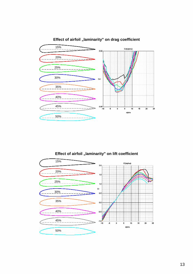
Effect of airfoil „laminarity” on drag coefficient
15%
20%
25%
30%
35%
40%
45%
50%
Effect of airfoil „laminarity” on lift coefficient
15%
20%
25%
30%
35%
40%
45%
50%

14
Effect of camber line shape on moment coefficient
35%
2°
4°
6°
28%
22%
15%
0°
Effect of camber line shape on gliding ratio
35%
2%
4%
6%
28%
22%
15%
0%
15
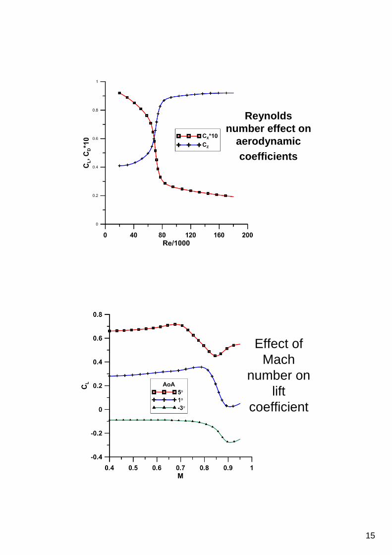
Reynolds number effect on
aerodynamic coefficients
Effect of Mach
number on lift
coefficient
16
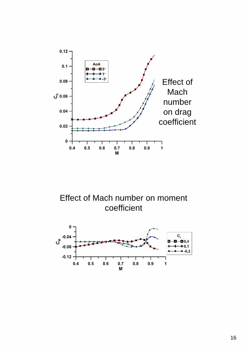
Effect of Mach
number on drag
coefficient
Effect of Mach number on moment coefficient

17
Critical Mach number
Historical values of an aeroplane airfoil thickness as a function of Mach number

18
Critical Mach number
Critical Mach number

19
Airfoil selectionCalculate Reynolds number for design airspeed
Re>3 000 000 3 000 000>Re>500 000 500 000>Re
Wortmann catalogue„StuttgarterProfilkatalog” Vol.1 i 2
Selig catalogue„Summary of low speed airfoil data” Vol.1-3„Airfoils at low speeds”
Calculate Mach number for maximum airspeed
Mmax<0,75
Mmax>0,75
Abbot catalogue „Theory of the wing section”, raport NACA 824, NASA TN D-7428
Supercritical airfoil eg. NASA SC(2) 714NASA TM X-1109NASA TM X-2977NASA TP 2969
Airfoil selection
Calculate Reynolds number for design airspeed
Find characteristics for Re des i Mdes
Calculate C L for design airspeed
Compare C D for C Ldes of available airfoils and select few best airfoils
Compare C Lmax of selected airfoils
Compare stall character of selected airfoils
Compare C M of selected airfoils
Select an airfoil with a combination of above featur es best suiting to the aeroplane mission

20
Remaining wing features
• Wing incidence;• Mean aerodynamic chord mac, • Wing area (reference area) S;• Wing span b;• Wing aspect ratio A;• Wing dihedral;• Wing sweep angle (leading edge ΛLE,
quarter chord Λc/4);• Taper ratio λ;• Geometrical and aerodynamic twist;• Winglets• Leading edges extensions;
c
Wing incidence angle
An angle between root chord and fuselage longitudinal axis
21
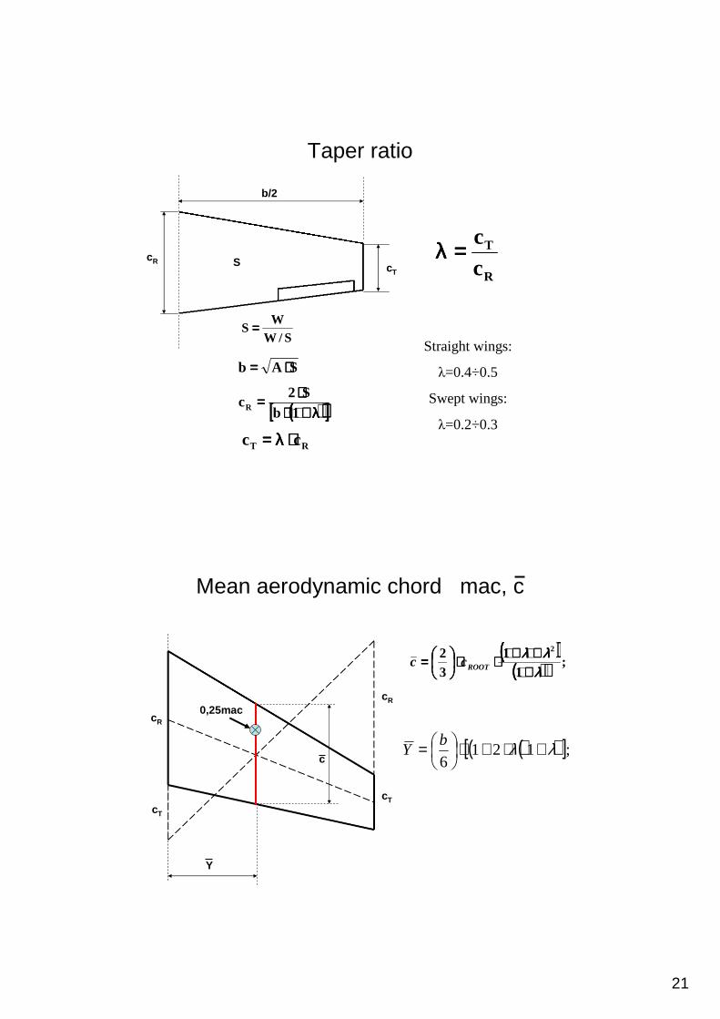
Taper ratio
S/WW
S ====
SAb ⋅⋅⋅⋅====
(((( ))))[[[[ ]]]]λλλλ++++⋅⋅⋅⋅⋅⋅⋅⋅====
1bS2
cR
R
T
cc====λλλλ
Straight wings:
λ=0.4÷0.5
Swept wings:
λ=0.2÷0.3
cT
cR
b/2
S
RT cc ⋅⋅⋅⋅λλλλ====
Mean aerodynamic chord mac, c
(((( ))))(((( )))) ;1
132 2
λλλλλλλλλλλλ
++++++++++++⋅⋅⋅⋅⋅⋅⋅⋅
==== ROOTcc
( )( )[ ];1216
λλ +⋅+⋅
= bY
cR
cT
cT
cR
c
Y
0,25mac

22
Vortices generated by a wing
Vortices generated by a wing and effect of aspect ratio on drag coefficient
Sb
A2
====eA
CCC
2L
0DD ⋅⋅⋅⋅⋅⋅⋅⋅ππππ++++====

23
Effect of aspect ratio (A, AR) on lift coefficient
Sb
A2
====
Helmbolt equation
2
2
ll
lL
ACC
ACC
++++
ππππ++++
ππππ
⋅⋅⋅⋅====αααααααα
αααααααα
Wing dihedral angle φ – an angle between chords’ plane and horizontal plane
ϕϕϕϕ
Wing dihedral
b1 b2
b3
b4
b3<b1=b2<b4
-5 ÷ 0-5 ÷ 00 ÷ 5Supersonic swept
-5÷-2-2 ÷ 23 ÷ 7Subsonic swept
0 ÷ 22 ÷ 45 ÷ 7Unswept
highmidlow
Wing position

24
Wing sweep c/t4/cLE ,, ΛΛΛΛΛΛΛΛΛΛΛΛ
ΛΛΛΛLEΛΛΛΛc/4
Line connecting quarter chords along the wing span
(((( )))) (((( ))))[[[[ ]]]]λλλλ++++⋅⋅⋅⋅λλλλ−−−−++++ΛΛΛΛ====ΛΛΛΛ 1A/1tantan 4/cLE
Wing sweep
Wing sweep reduces effective Mach number.
ΛΛΛΛLE
ΛΛΛΛt/c
M
Meff=M∞cos(ΛΛΛΛLE)
Mkryt~1/cosm(ΛΛΛΛLE)
qeff=q∞cos2(ΛΛΛΛLE)
W~tan2(ΛΛΛΛLE)
McosΛΛΛΛLE

25
Wing sweep effect on dCL/dα
(((( )))) (((( ))))
ββββΛΛΛΛ++++⋅⋅⋅⋅ββββ⋅⋅⋅⋅++++++++
⋅⋅⋅⋅ππππ⋅⋅⋅⋅====αααα
2c/t
22
L
tan1A42
A2d
dC
2effM1 −−−−====ββββ
LEeff cosMM ΛΛΛΛ==== ∞∞∞∞
Wing sweep effect on separation

26
Wing sweep at supersonic speeds
Winglets

27
Wing twist
Geometric twist
Aerodynamic twist
Wing twist
Geometric twist
Aerodynamic twist
28
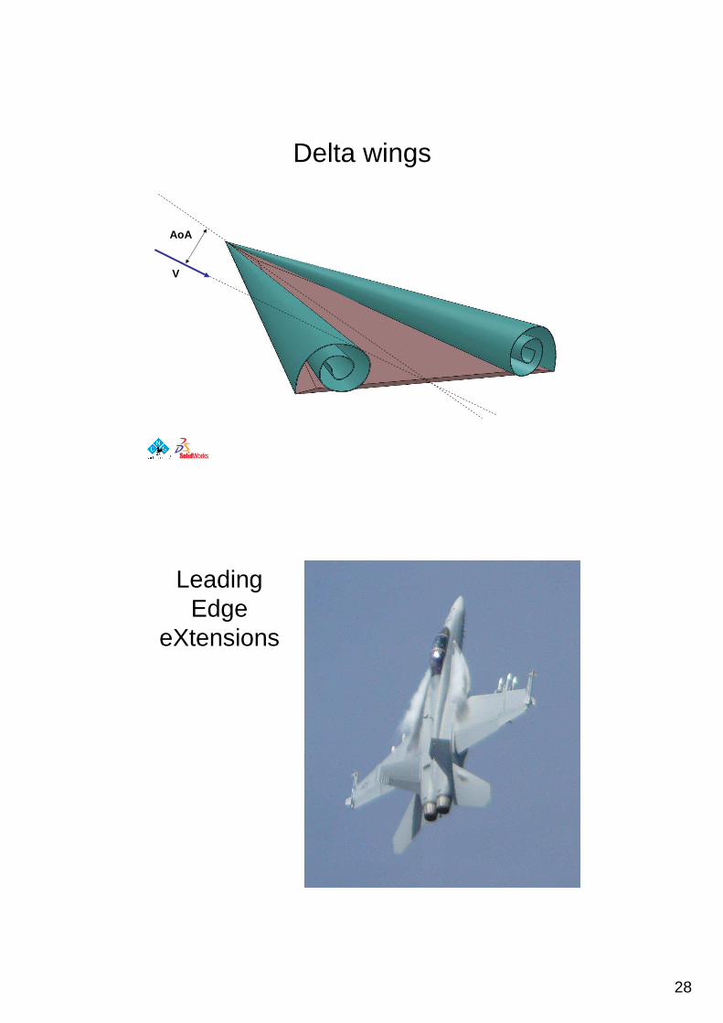
Delta wings
AoA
V
Leading Edge
eXtensions

29
LEX effect on lift coefficient
Vortex generators RAF Museum Hendon

30