Embed Size (px)
Citation preview

BIRKETT WB SERIES SAFETY RELIEF VALVES
© 2017 Emerson. All Rights Reserved.
Spring loaded safety relief valves with a full lift and full nozzle to relieve excess pressure safely in a variety of process vessels
FEATURES
• Full nozzle, full lift provides high discharge coefficients and high capacities.
• Broad selection of valve types: conventional or bellows for gas or liquid service enables optimum valve selection.
• Wide range of materials provides solutions for any application.
• Lightweight construction reduces handling and shipping costs and benefits offshore service.
• Seat leakage integrity minimizes fugitive emissions.
• Interchangeable parts enable simple modification from gas to liquid and conventional to bellows.
• In-situ testing capability reduces maintenance costs.
• Reduced number of parts minimizes inventory and reduces maintenance costs.
• Valves conform to API 526 pressure/temperature ranges, orifice areas and dimensions.
• Extensive accessory range enables valves to be adapted to meet specific code and application requirements.
• Optional cleaning for cryogenic and oxygen services available.
GENERAL APPLICATION
The WB series is designed to relieve excess pressure safely in pumps, pipe work, tanks, calorifiers, gas and oil separators and other process vessels. Models are available for gas, steam, vapor and liquid applications.
TECHNICAL DATA
Materials: Carbon steel, stainless steelSizes: 1” x 2” to 8” x 10” (DN 25 to
DN 200)Connections Flanged ANSI 150# to
2500# RF or RTJPressure: Up to 6000 psig (414 barg)Temperature range: -450°F to 1000°F
(-268°C to 538°C)
Emerson.com/FinalControl VCTDS-03791-EN 18/01

2
Typical liquid relief valve disc
BIRKETT WB SERIES SAFETY RELIEF VALVESOVERVIEW
MODEL OPTIONS
The WB Series is available in four different valve types to suit differing service requirements:WB400 - conventional gas type.WB300 - bellows gas type.WB200 - conventional liquid type.WB100 - bellows liquid type.
TYPICAL LIQUID RELIEF VALVE DISC
CONVENTIONAL SAFETY RELIEF VALVES
These valves can be used on systems where the discharge is relatively simple. The pressure in the discharge system can be atmospheric, at a constant level or where it may build up to a maximum of 10% of the set pressure. When a constant back pressure exists, the valve should be set at the differential pressure.
BELLOWS SAFETY RELIEF VALVES
WB Series bellows valves are statically balanced and can be used on more complex discharge systems such as common discharge manifolds and flares where several valves may discharge. These types of system create a variable superimposed back pressure. The balanced bellows unit cancels out the effects of variable back pressure on the valve’s set pressure.
Gas and vapor serviceThe gas/vapor disc can be distinguished by a flat underside, unlike the cone profile of the liquid disc.
Liquid serviceValves operating on liquid service require a modified design to cope with the differing dynamics of flowing liquids.
A contoured plug disc is used to minimize the initial flow rate, eliminating any potential inlet pressure drops due to excessive valve lift. The valve will simmer until sufficient pressure is available to generate lift. Once this has occurred, the lift will stabilise to suit the flow and pressure conditions required. This avoids the problem of ‘chatter’; the rapid opening and closing of the valve which can have a damaging effect on the disc and nozzle causing the valve to leak.
Standards and approvalsQuality standard: ISO 9001:2008Boiler and pressure vessels: ASME VIII PED 97/23/ECMechanical Engineering Directive: ATEX 94/9/ECSizing and selection: API 520: Part 1 ISO 4126Dimensions: API 526Leakage rates: API 527Flange ratings: ANSI B16.5

3
1. Valves can be supplied suitable for application of ‘in-situ’ set pressure verification devices.2. Wide accessories range to comply with international codes and suit system requirements.3. High performance springs designed specifically to guarantee set point repeatability.4. Optional auxiliary back-up piston for balanced bellows valves ensures fail-safe operation
should bellows fail.5. Guiding components material selection, self aligning disc and spindle pivot point,
ensure correct alignment and no galling of guiding surfaces.6. Bellows ensures correct valve performance under difficult back pressure conditions.7. Specific gas and liquid trim designs give stable operation and eliminate the damaging effect
of chatter.8. Choice of nozzle and disc materials and superior lapping techniques provides seat tightness
to API 527/ASME VIII.9. Valve reseating pressure (blow down) can be adjusted simply to suit special or specific
performance requirements.10. Carefully located and securely attached nozzle design avoids transmission of pipe stresses
to the nozzle/disc mating surfaces.11. Standardized dimensions to API 526 allow confident pipework layout detailing.
BIRKETT WB SERIES SAFETY RELIEF VALVESFEATURES
6. Bellows (not shown)
9. Adjustable blow down
8. Seat integrity
11. API 526 face to face dimensions
7. Trim
10. Nozzle design
5. Guiding
2. Accessories
4. Bellows back up piston (not shown)
1. Insitu testing
3. High performance springs

4
BIRKETT WB SERIES SAFETY RELIEF VALVESOPERATION
PRINCIPLE OF OPERATION
Safety relief valves use a spring force to hold a disc against a nozzle. Under normal system operating pressure, the valve will remain closed as the spring force is greater than the inlet system pressure force. The valve opens when the system pressure force becomes greater than the closing force of the spring.
The WB Series are designed to have a short simmer, open rapidly to full lift position and then re-seat at a controlled shut off pressure.
This is demonstrated in the graph below, which shows the valve action and corresponding pressure at the valve inlet.
POPPING AND BLOWDOWN
The difference between the set pressure and the re-seating pressure is known as blowdown.The valve’s opening and closing characteristics can be controlled by the adjustment of a blowdown ring, as its position affects the shape and volume of the huddling chamber. When the blowdown ring is adjusted to its top position, the exit area from the huddling chamber is restricted to its minimum. The valve will pop distinctly with a short simmer and long blowdown. When it is in its lowest position there is a maximum exit area from the huddling chamber and the valve will have a longer simmer with a shorter blowdown. The blowdown ring can be positioned between these two extremes to give the required performance but it is usually factory set to achieve re-seating 7-10% below set pressure.
Popping pressureSet pressure
Pressure
Overpressure
Blowdown
Re-seat pressure
Stage 1 Stage 2 Stage 3 Stage 4
Set point Popping point Full lift position Re-seat point
Simmer
Lift
Spring force
System pressure force

5
BIRKETT WB SERIES SAFETY RELIEF VALVESOPERATION
LIFT CYCLE
Stage 1 - ClosedInlet pressure < set pressure
Inlet pressure is below the set pressure. The valve is closed and there is no flow through the valve.
Huddling chamber
Reaction hood
Exit area
Blowdown ringInlet
Stage 2 - SimmeringInlet pressure is = > set pressure and < popping pressure
Inlet pressure increases to set pressure. At this point, the spring force and system pressure force are equal; a further rise in inlet pressure will then begin to lift the disc slightly. A small amount of fluid is released into the huddling chamber (the valve simmers). The system fluid is now acting on a larger area inside the huddling chamber.
Stage 3 - Popping and openingInlet pressure = > popping pressure, valve fully open
The inlet pressure acting on a larger area produces a significant force to accelerate the opening. A combination of this pressure force, the kinetic energy from the fluid within the nozzle and the deflection force of the fluid flow turning through the reaction hood is transformed into disc lifting force. The valve pops open at < 5% overpressure and the valve reaches the full open position at 110% of set pressure, in accordance with international codes.
Stage 4 - ReseatingInlet pressure falls to re-seating pressure
As system pressure starts to fall, the force from the spring begins to close the valve. Typically, the system pressure falls between 5-10% below the valve set pressure at which point the spring force accelerates the valve disc to re-seat the valve.
6
BIRKETT WB SERIES SAFETY RELIEF VALVESOPERATION
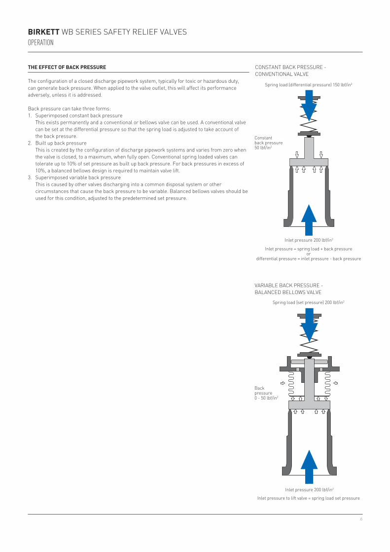
THE EFFECT OF BACK PRESSURE
The configuration of a closed discharge pipework system, typically for toxic or hazardous duty, can generate back pressure. When applied to the valve outlet, this will affect its performance adversely, unless it is addressed.
Back pressure can take three forms:1. Superimposed constant back pressure This exists permanently and a conventional or bellows valve can be used. A conventional valve
can be set at the differential pressure so that the spring load is adjusted to take account of the back pressure.
2. Built up back pressure This is created by the configuration of discharge pipework systems and varies from zero when
the valve is closed, to a maximum, when fully open. Conventional spring loaded valves can tolerate up to 10% of set pressure as built up back pressure. For back pressures in excess of 10%, a balanced bellows design is required to maintain valve lift.
3. Superimposed variable back pressure This is caused by other valves discharging into a common disposal system or other
circumstances that cause the back pressure to be variable. Balanced bellows valves should be used for this condition, adjusted to the predetermined set pressure.
CONSTANT BACK PRESSURE - CONVENTIONAL VALVE
VARIABLE BACK PRESSURE - BALANCED BELLOWS VALVE
Spring load (differential pressure) 150 lbf/in2
Spring load (set pressure) 200 lbf/in2
Constant back pressure 50 lbf/in2
Inlet pressure 200 lbf/in2
Back pressure 0 - 50 lbf/in2
Inlet pressure = spring load + back pressure or
differential pressure = inlet pressure - back pressure
Inlet pressure 200 lbf/in2
Inlet pressure to lift valve = spring load set pressure

7
BIRKETT WB SERIES SAFETY RELIEF VALVESMATERIALS OF CONSTRUCTION
PARTS LISTItem Part Carbon steel Stainless steel1 Body SA 216-WCB CARB ST SA 351-CF8M ST ST2 Casing SA 216-WCB CARB ST SA 351-CF8M ST ST3 Cap SA 216-WCB CARB ST SA 351-CF8M ST ST4* Nozzle 316 ST ST 316 ST ST5* Disc 316 ST ST 316 ST ST6* Disc holder ASTM A479-316L ASTM A479-316L8 Blowdown ring SA 351-CF8M ST ST SA 351-CF8M ST ST9 Guide assy CARBON ST/17-4 ST ST 316L/17-4 ST ST10* Spindle ASTM A479-431 ASTM A479-43111 Lower spring plate ASTM A108-1021/Ni PLT ASTM A479-43112 Adjusting screw ASTM A479-410 ASTM A479-41013 Locking nut ASTM A108-1021 ASTM A479-316L14 Setting screw ASTM A479-431 ASTM A479-43115 Setting screw rod ASTM A479-316L ASTM A479-316L18 Stud SA 193-B7 CR/MOL ST SA 193-B8T ST ST19 Nut SA 194-2H CARB ST SA 194-8T ST ST22* Spring Carbon steel ASTM A313-31627* Body gasket ST-706 ST-70628* Cap gasket ST-706 ST-70629* Set screw gasket ST-706 ST-70631* Ball AISI 440C ST ST AISI 440C ST ST32 Upper spring plate ASTM A108-1021/Ni PLT ASTM A479-43133 Data plate 321 ST ST 321 ST ST34 Hammer drive screw Electro brassed ST ASTM A479-316L35 Grooved pin ASTM A479-431 ASTM A479-43142 Drain plug HTS HOLO-KROME ASTM A479-316L80* Circlip ASTM A313-316 ASTM A313-316 * Recommended spares
WB 400 - CONVENTIONAL GAS TYPE(up to and including class 600)

8
BIRKETT WB SERIES SAFETY RELIEF VALVESMATERIALS OF CONSTRUCTION
PARTS LISTItem Part Carbon steel Stainless steel1 Body SA 216-WCB CARB ST SA 351-CF8M ST ST2 Casing SA 216-WCB CARB ST SA 351-CF8M ST ST3 Cap SA 216-WCB CARB ST SA 351-CF8M ST ST4* Nozzle 316 ST ST 316 ST ST5* Disc 316 ST ST 316 ST ST6* Disc holder Included in item 23 Included in item 238 Blowdown ring SA 351-CF8M ST ST SA 351-CF8M ST ST9 Guide Assy CARBON ST/17-4 ST ST 316 L/17-4 ST ST10* Spindle ASTM A479-431 ASTM A479-43111 Lower spring plate ASTM A108-1021/Ni PLT ASTM A479-43112 Adjusting screw ASTM A479-410 ASTM A479-41013 Locking nut ASTM A108-1021 ASTM A479-316L14 Setting screw ASTM A479-431 ASTM A479-43115 Set screw rod ASTM A479-316L ASTM A479-316L18 Stud SA 193-B7 CR/MOL ST SA 193-B8T ST ST19 Nut SA 194-2H CARB ST SA 194-8T ST ST22* Spring Carbon steel ASTM A313-31623* Bellows assembly ASTM A479-316L/SA240-316L ASTM A479-316L/SA240-316L27* Body gasket ST-706 ST-70628* Cap gasket ST-706 ST-70629* Set screw gasket ST-706 ST-70631* Ball AISI 440C ST ST AISI 440C ST ST32 Upper spring plate ASTM A108-1021/Ni PLT ASTM A479 43133 Data plate 321 ST ST 321 ST ST34 Hammer drive screw Electro brassed ST ASTM A479-316L35 Grooved pin ASTM A479-431 ASTM A479-43142 Drain plug HTS holo-krome ASTM A479-316L80* Circlip ASTM A313-316 ASTM A313-316 * Recommended spares
WB 300 - BALANCED BELLOWS GAS TYPE(up to and including class 600)
9
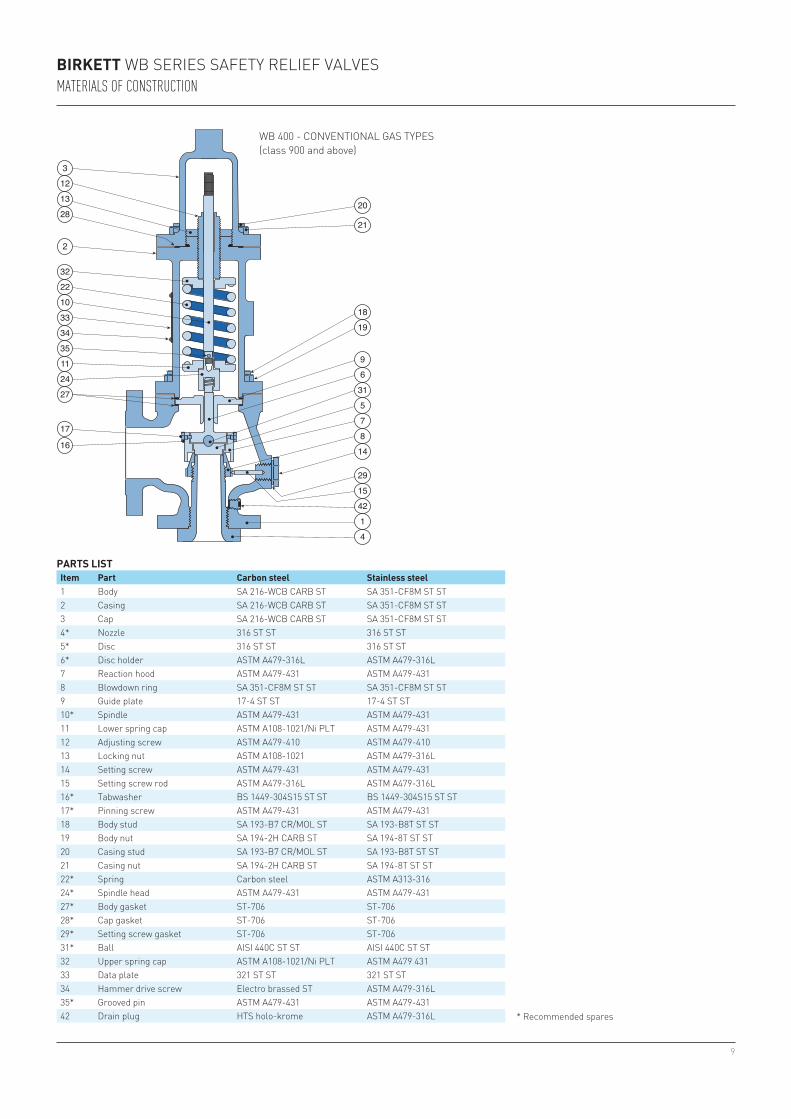
BIRKETT WB SERIES SAFETY RELIEF VALVESMATERIALS OF CONSTRUCTION
PARTS LISTItem Part Carbon steel Stainless steel1 Body SA 216-WCB CARB ST SA 351-CF8M ST ST2 Casing SA 216-WCB CARB ST SA 351-CF8M ST ST3 Cap SA 216-WCB CARB ST SA 351-CF8M ST ST4* Nozzle 316 ST ST 316 ST ST5* Disc 316 ST ST 316 ST ST6* Disc holder ASTM A479-316L ASTM A479-316L7 Reaction hood ASTM A479-431 ASTM A479-4318 Blowdown ring SA 351-CF8M ST ST SA 351-CF8M ST ST9 Guide plate 17-4 ST ST 17-4 ST ST10* Spindle ASTM A479-431 ASTM A479-43111 Lower spring cap ASTM A108-1021/Ni PLT ASTM A479-43112 Adjusting screw ASTM A479-410 ASTM A479-41013 Locking nut ASTM A108-1021 ASTM A479-316L14 Setting screw ASTM A479-431 ASTM A479-43115 Setting screw rod ASTM A479-316L ASTM A479-316L16* Tabwasher BS 1449-304S15 ST ST BS 1449-304S15 ST ST17* Pinning screw ASTM A479-431 ASTM A479-43118 Body stud SA 193-B7 CR/MOL ST SA 193-B8T ST ST19 Body nut SA 194-2H CARB ST SA 194-8T ST ST20 Casing stud SA 193-B7 CR/MOL ST SA 193-B8T ST ST21 Casing nut SA 194-2H CARB ST SA 194-8T ST ST22* Spring Carbon steel ASTM A313-31624* Spindle head ASTM A479-431 ASTM A479-43127* Body gasket ST-706 ST-70628* Cap gasket ST-706 ST-70629* Setting screw gasket ST-706 ST-70631* Ball AISI 440C ST ST AISI 440C ST ST32 Upper spring cap ASTM A108-1021/Ni PLT ASTM A479 43133 Data plate 321 ST ST 321 ST ST34 Hammer drive screw Electro brassed ST ASTM A479-316L35* Grooved pin ASTM A479-431 ASTM A479-43142 Drain plug HTS holo-krome ASTM A479-316L
WB 400 - CONVENTIONAL GAS TYPES(class 900 and above)
* Recommended spares
10
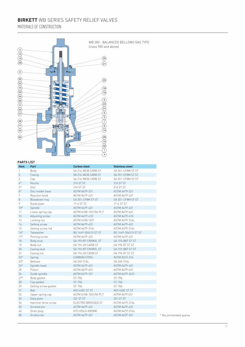
BIRKETT WB SERIES SAFETY RELIEF VALVESMATERIALS OF CONSTRUCTION
PARTS LISTItem Part Carbon steel Stainless steel1 Body SA 216-WCB CARB ST SA 351-CF8M ST ST2 Casing SA 216-WCB CARB ST SA 351-CF8M ST ST3 Cap SA 216-WCB CARB ST SA 351-CF8M ST ST4* Nozzle 316 ST ST 316 ST ST5* Disc 316 ST ST 316 ST ST6* Disc holder base ASTM A479-321 ASTM A479-3217 Reaction hood ASTM A479-431 ASTM A479-4318 Blowdown ring SA 351-CF8M ST ST SA 351-CF8M ST ST9 Guide plate 17-4 ST ST 17-4 ST ST10* Spindle ASTM A479-431 ASTM A479-43111 Lower spring cap ASTM A108-1021/Ni PLT ASTM A479-43112 Adjusting screw ASTM A479-410 ASTM A479-41013 Locking nut ASTM A108-1021 ASTM A479-316L14 Setting screw ASTM A479-431 ASTM A479-43115 Setting screw rod ASTM A479-316L ASTM A479-316L16* Tabwasher BS 1449-304S15 ST ST BS 1449-304S15 ST ST17* Pinning screw ASTM A479-431 ASTM A479-43118 Body stud SA 193-B7 CR/MOL ST SA 193-B8T ST ST19 Body nut SA 194-2H CARB ST SA 194-8T ST ST20 Casing stud SA 193-B7 CR/MOL ST SA 193-B8T ST ST21 Casing nut SA 194-2H CARB ST SA 194-8T ST ST22* Spring CARBON STEEL ASTM A313-31623* Bellows SA 240-316L SA 240-316L24* Spindle head ASTM A479-431 ASTM A479-43125 Piston ASTM A479-431 ASTM A479-43126 Guide spindle ASTM A479-321 ASTM A479-343127* Body gasket ST-706 ST-70628 Cap gasket ST-706 ST-70629 Setting screw gasket ST-706 ST-70631 Ball AISI 440C ST ST AISI 440C ST ST32 Upper spring cap ASTM A108-1021/Ni PLT ASTM A479 43133 Data plate 321 ST ST 321 ST ST34 Hammer drive screw ELECTRO BRASSED ST ASTM A479-316L35 Grooved pin ASTM A479-431 ASTM A479-43142 Drain plug HTS HOLO-KROME ASTM A479-316L50 Grubscrew ASTM A479-321 ASTM A479-321
WB 300 - BALANCED BELLOWS GAS TYPE(class 900 and above)
* Recommended spares
11
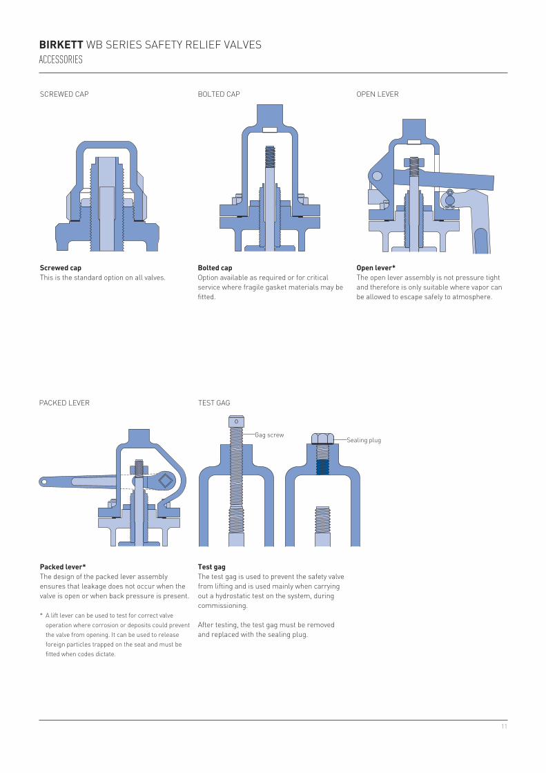
BIRKETT WB SERIES SAFETY RELIEF VALVESACCESSORIES
Screwed capThis is the standard option on all valves.
SCREWED CAP
PACKED LEVER
BOLTED CAP OPEN LEVER
TEST GAG
Gag screwSealing plug
Packed lever*The design of the packed lever assembly ensures that leakage does not occur when the valve is open or when back pressure is present.
* A lift lever can be used to test for correct valve operation where corrosion or deposits could prevent the valve from opening. It can be used to release foreign particles trapped on the seat and must be fitted when codes dictate.
Bolted capOption available as required or for critical service where fragile gasket materials may be fitted.
Open lever*The open lever assembly is not pressure tight and therefore is only suitable where vapor can be allowed to escape safely to atmosphere.
Test gagThe test gag is used to prevent the safety valve from lifting and is used mainly when carrying out a hydrostatic test on the system, during commissioning.
After testing, the test gag must be removed and replaced with the sealing plug.

12
BIRKETT WB SERIES SAFETY RELIEF VALVESACCESSORIES
Ferrule (government ring)A ferrule, sometimes known as a government ring, is a collar fitted beneath the head of the pressure adjusting screw. Some authorities will require a ferrule to be fitted to prevent unauthorized interference with the set pressure.
FERRULE STEAM JACKET
AUXILIARY BACK-UP PISTON
Ferrule
SOFT SEAT
Steam jacketSome process media can solidify or form crystals if they cool within the system. The medium within the valve nozzle is not in the flow path and therefore can cool. The valve may not lift should the medium solidify, crystallise or if sublimation of vapor was to occur within the nozzle.
The steam jacket is designed to keep the process medium hot, helping to maximize plant safety. It has both an inlet and outlet so that low pressure steam can be passed through the jacket, keeping the valve hot. This allows the valve to stay operational, enabling it to relieve pressure successfully should an overpressure situation occur.
The steam jacket is manufactured from material that is compatible with the valve body and the connections to the jacket can be either flanged or screwed.
Auxiliary back-up pistonA potentially dangerous situation can arise if the bellows fails. The back pressure causes an ‘out-of-balance’ condition which may cause:
1. Increase in set pressure.2. Decrease in flow capacity.3. Increase in re-seat pressure.
Soft seatAn O-ring seal offers maximum seat tightness, over and above that of the standard metal-to-metal seats. A wide range of seal materials is available including FKM, Nitrile, Kalrez and PTFE.
Specify a soft seat for high integrity seat leakage.
Specifying bellows valves with an auxiliary back-up piston ensures these do not occur. The piston has the same effective diameter as the failed bellows, so any effect of the back pressure increasing the set pressure is counteracted by an upward thrust of the piston. The WB 300 valve incorporates the auxiliary back-up piston as standard in all pressure classes 900 and above and as an optional feature for class 600 and below.
Specify the auxiliary back-up piston to ensure absolute safety.

13
SELECTION GUIDEExample: 4 L 6 H 1 2 1 1 1 2 BModel1 1" 4 4"1.5 1½" 6 6"2 2" 8 8"3 3"Orifice designation D to T Outlet diameter2 2" 6 6"3 3" 8 8"4 4" 10 10"DesignH ANSI 150, 300 and 600 / ANSI 900, 1500 and 2500Valve type1 Liquid bellows2 Liquid conventional3 Vapor bellows4 Vapor conventionalANSI flange rating (inlet x outlet)1 150 x 150 5 900 x 3002 300 x 150 6 1500 x 1503 600 x 150 7 1500 x 3004 900 x 150 8 2500 x 300O SpecialFlange face1 ANSI RF x RF2 ANSI RTJ inlet x RFO SpecialBody material1 Carbon steel WCB 5 Carbon steel low temperature LCB2 Carbon steel WCB NACE 6 Bronze3 Stainless steel CF8M NACE 8 Carbon steel WC6 - 0.5% Moly4 Stainless steel CF8M 9 Hastelloy BO SpecialSpring material1 Carbon steel A Aluminum coated CS2 Stainless steel 316 N Stainless steel PH 17/46 Tungsten alloy Q Stainless steel PH 17/4 NACE9 Hastelloy B T Aluminum coated tungstenO Special Z Inconel X750Trim material nozzle and disc1 Stainless steel PH 17/4 5 Stainless steel 316 stellited2 Stainless steel 316 6 Monel3 Aluminum bronze / Monel 7 Stainless steel 3044 Hastelloy B O SpecialAccessoriesB Auxiliary back-up piston M Open leverC Bolted cap P Packed leverD Screwed cap R Soft seatF Ferrule (Government ring) S Special featureG Test gag 3 WB300 bellowsH* High pressure
* In some instances when both high pressures and alloy springs are required, the ‘H’ needs adding to accessories.
BIRKETT WB SERIES SAFETY RELIEF VALVESSELECTION

14
Neither Emerson, Emerson Automation Solutions, nor any of their affiliated entities assumes responsibility for the selection, use or maintenance of any product. Responsibility for proper selection, use, and maintenance of any product remains solely with the purchaser and end user.
Emerson Automation Solutions, Emerson and the Emerson logo are trademarks and service marks of Emerson Electric Co. All other marks are the property of their respective owners.
The contents of this publication are presented for informational purposes only, and while every effort has been made to ensure their accuracy, they are not to be construed as warranties or guarantees, express or implied, regarding the products or services described herein or their use or applicability. All sales are governed by our terms and conditions, which are available upon request. We reserve the right to modify or improve the designs or specifications of such products at any time without notice.
Emerson.com/FinalControl