Embed Size (px)
Citation preview
BISHOP CREEK HYDROELECTRIC SYSTEM BISHOP CREEK BISHOP VICINITY INYO COUNTY CALIFORNIA
HAER No. CA-145
4-£oHV,
PHOTOGRAPHS
WRITTEN HISTORICAL AND DESCRIPTIVE DATA
HISTORIC AMERICAN ENGINEERING RECORD NATIONAL PARK SERVICE
WESTERN REGION DEPARTMENT OF THE INTERIOR
SAN FRANCISCO, CALIFORNIA 94107
HISTORIC AMERICAN ENGINEERING RECORD
Bishop Creek Hydroelectric System Bishop Creek Bishop Vicinity Inyo County California
HAER No. CA-145
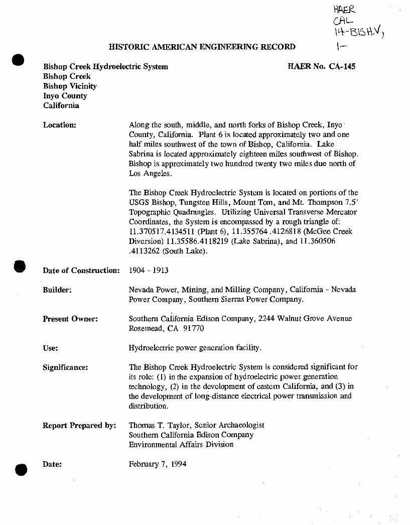
Location: Along the south, middle, and north forks of Bishop Creek, Inyo County, California. Plant 6 is located approximately two and one half miles southwest of the town of Bishop, California. Lake Sabrina is located approximately eighteen miles southwest of Bishop. Bishop is approximately two hundred twenty two miles due north of Los Angeles.
The Bishop Creek Hydroelectric System is located on portions of the USGS Bishop, Tungsten Hills, Mount Tom, and Mt. Thompson 7.5' Topographic Quadrangles. Utilizing Universal Transverse Mercator Coordinates, the System is encompassed by a rough triangle of: 11.370517.4134511 (Plant 6), 11.355764 .4126818 (McGee Creek Diversion) 11.35586.4118219 (Lake Sabrina), and 11.360506 .4113262 (South Lake).
Date of Construction: 1904 - 1913
Builder:
Present Owner:
Use:
Significance:
Report Prepared by:
Nevada Power, Mining, and Milling Company, California - Nevada Power Company, Southern Sierras Power Company.
Southern California Edison Company, 2244 Walnut Grove Avenue Rosemead, CA 91770
Hydroelectric power generation facility.
The Bishop Creek Hydroelectric System is considered significant for its role: (1) in the expansion of hydroelectric power generation technology, (2) in the development of eastern California, and (3) in the development of long-distance electrical power transmission and distribution.
Thomas T. Taylor, Senior Archaeologist Southern California Edison Company Environmental Affairs Division
Date: February 7, 1994
BISHOP CREEK HYDROELECTRIC SYSTEM BISHOP CREEK BISHOP VICINITY INYO COUNTY CALIFORNIA
HAER No. CA-145 (Page 2)
PARTI DESCRIPTION OF THE BISHOP CREEK SYSTEM
Basic Components of Hydroelectric Systems
The use of falling water to operate wheels and produce mechanical energy dates back at least four centuries. Until the nineteenth century, water power was essentially the only practical power source for operating large-scale industrial machines, other than draft animal and human energies. With the advent of the Industrial Revolution in the eighteenth century came the development of steam, the internal combustion engine, and the harnessing of electrical energy. The first electrical generator was perfected in 1867, and by the 1880s electrical energy was being experimentally transmitted significant distances, both in Europe and the United States. During the last decade of the nineteenth century and the first quarter of the twentieth century, details of electrical generation and transmission were perfected and demonstrated, and electricity was established as the power of choice. Numerous power-generating systems were established to exploit the demand. In the western United States, falling water, used effectively for hydraulic mining since the mid-nineteenth century, was the obvious early energy choice to drive electrical generators. Hydroelectric power remains one of the most cost-efficient means of energy available.
There are two basic types of hydroelectric systems. One, low-head hydro, uses a large volume or mass of water falling a relatively short distance, or head, to turn a reaction, or screw- shaped turbine. These types are prevalent in the eastern United States where water volumes are high and topography is relatively low. The other, high-head hydro, exploits lower water volumes and greater topographic relief to drop water longer distances, sometimes as much as several thousand feet, to turn a impulse or bucketed-wheel turbine. The Bishop Creek System utilizes the high-head technology.
Location and Setting of the Bishop Creek System
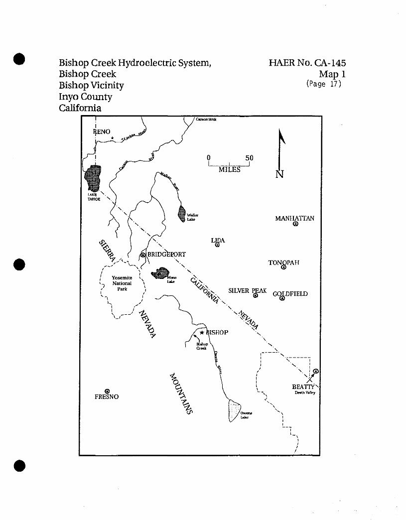
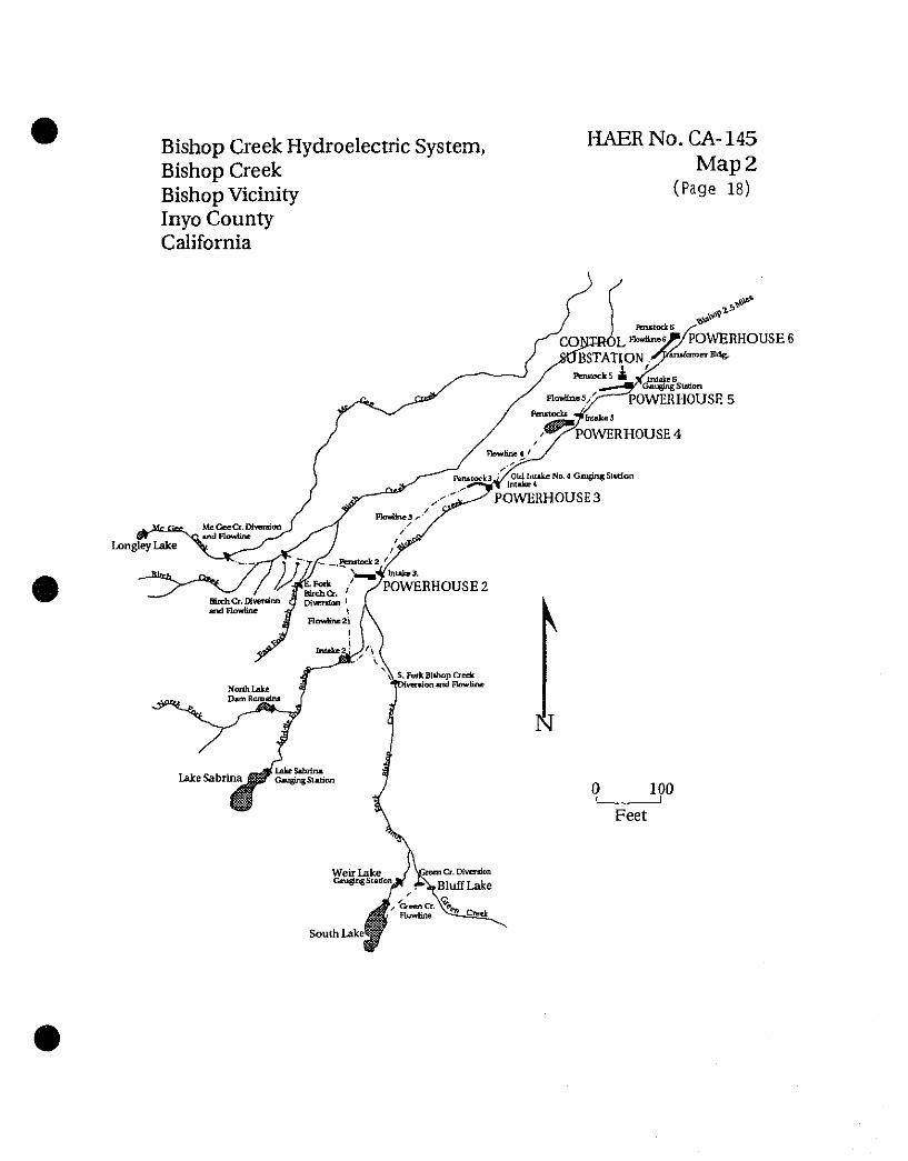
The Bishop Creek Hydroelectric System consists of five sets of independent, high-head, impulse water wheel, electrical power-generating sub-systems (plants) established at various elevations along the south, middle, and north forks of Bishop Creek on the eastern slopes of the Sierra Nevada Mountains, Inyo County, California (Map 1). System structures include five powerhouses, one control station, two gauging stations, ten flowlines, ten intakes, seven penstocks, four diversions, four reservoirs, four dams, worker housing, and other associated support buildings. Plant 6, the furthest down-stream System facility, is located approximately two and one half miles southwest of the town of Bishop, California. Lake Sabrina, the most distant System reservoir, is located approximately eighteen miles southwest of Bishop. Bishop
BISHOP CREEK HYDROELECTRIC SYSTEM BISHOP CREEK BISHOP VICINITY INYO COUNTY CALIFORNIA
HAER No. CA-145 (Page 3)
is approximately two hundred twenty two miles due north of Los Angeles. Map 2 shows the Bishop Creek System layout. Photograph 145-1 shows a 1994 aerial view of Bishop Creek looking west towards the Sierra Nevada Mountains; photograph 145-2 shows a 1994 aerial view of Bishop Creek looking northeast towards Owens Valley and the White Mountains, with South Lake in the foreground.
From near the 13,000 foot plus crest of the Sierra Nevada Mountains, the bed of Bishop Creek and its upper tributaries drop over 4,000 vertical feet over a horizontal distance of 14 miles to the floor of Owens Valley. For most of is length Bishop Creek flows in steep-sided canyons exhibiting the classical glacial-formed U shape. The north wall of the canyon is composed of a glacial moraine which forms a natural, almost continuous ridge paralleling the creek. In the lower course, additional local relief has been created through stream dissection of the moraine from relatively recent fluvial erosion. Except for the Sierra summit, which receives substantial precipitation, the majority of the Bishop Creek watershed falls within the arid, Sierra Nevada rain shadow.
•
This geography was exploited to create the high head Bishop Creek System by utilizing the relatively steep terrain and even topography left by Pleistocene glacial action. Bishop Creek is a run-of-the-river type system whereby stream water is diverted at various points, transported through flowlines at a gradient far less than the stream channel, and ultimately dropped this elevational distance through penstocks, or pressure pipes, down to the impulse wheels in the powerhouses. The glacial moraine of the Bishop Canyon north wall, a perfect base upon which to build flowlines, was exploited for this purpose for Plants 2, 3 and 4. Plants 5 and 6, located below Bishop Canyon, rely on the natural gradient of the large alluvial fan emanating from Bishop Canyon for their head. The reservoirs on the Bishop Creek South and Middle Forks were built to regulate flow, rather than to create head.
The headwaters of the South Fork of Bishop Creek are confined in Bluff Lake and South (Hillside) Lake. Lake Sabrina impounds water from the Middle Fork of Bishop Creek, and Longley Lake collects a portion of the McGee Creek flow that is diverted into the Bishop Creek System. These reservoirs all collect and store snow-melt from the high Sierra crest, keeping it ready for release when needed. Thus, water stored during high flow, which is usually during winter and spring, can be released during summer and fall low-flow periods.
Waters from Green Creek and Bluff Lake are diverted to South Lake on the South Fork of Bishop Creek. From the South Fork Dam to Coates Meadow (a distance of seven and one half miles), the stream travels the natural channel toward its confluence with the Middle Fork. The South Fork Bishop Creek dam and flowline diverts a portion of this water from Coates
BISHOP CREEK HYDROELECTRIC SYSTEM BISHOP CREEK BISHOP VICINITY INYO COUNTY CALIFORNIA
HAER No. CA-145 (Page 4)
Meadow around the east end of Table Mountain into a stabilizing reservoir (Intake 2). Water from Lake Sabrina follows the natural channel from the dam outlet into Intake 2 (a distance of approximately four miles). Waters from Birch and McGee creeks enter the system below Intake 2.
From this point on, the water transportation pattern is repeated from plant to plant: water is taken from an intake or equalizing pond and transported via flowlines and penstock to the next plant. In this way, the water of Bishop Creek is used five times on its journey down the steep canyon to the edge of Owens Valley. From Intake 2 to the tailrace at Plant 6 the water drops 3,590 feet (Fowler 1923:777). After leaving Plant 6, the water is used for irrigation before final disposition into Owens River. Photograph 145-3 shows the repeat pattern of the flowlines in this 1994 view looking northeast towards Plant 2. Plant 2 flowline can be seen at photo-left running near the crest of the glacial moraine before connecting with the penstock to Plant 2; the Plant 3 flowline can be seen departing Plant 2 at photo-center and proceeding in an arc down canyon towards Plant 3.
For most of its history, Bishop Creek was a fairly remote place, and as initially conceived, the electrical generators of the Bishop Creek System required the constant presence of operators. The need for large operator/maintenance crews coupled with the remote location led to the development of communities of worker housing around the plants. By the 1960s, two things occurred that portended irretrievable changes to the character of worker life on the Bishop Creek System. First, in 1965-66 a new two lane all weather highway (new Highway 168) was constructed between Bishop and Lake Sabrina. Old Highway 168 (the County Road) was the through access road for the Bishop Creek Hydroelectric System; it passed directly through the community of worker housing and operating headquarters surrounding Plant 4. Sections of this road, especially those between Plants 3 and 4, were one lane with no turnouts. The new Highway 168 is an all-weather two lane road with wide shoulders and minimal curves that completely bypasses the treacherous parts of the old road between Plants 3 and 4. This new road provides a much quicker and safer commute between the town of Bishop and the Bishop Creek facilities, and prompted many of the System workers to relocate to Bishop where schools, shopping and other "urban" amenities were available. Also about this time, measures to enable a more automated System operation were initiated; these changes would eventually lead to the 1994 Eastern Automation Project. The new road and the move toward automation combined to eliminate the need for worker housing at the powerhouses, and in 1978-79 houses at Plants 2, 3, and 5 were removed. A substantial community of worker housing is still present at Plant 4 along with most of the System operations headquarters offices and support facilities. A smaller community of worker housing is present at Control Station, and a single home is present at Plant 6.
BISHOP CREEK HYDROELECTRIC SYSTEM BISHOP CREEK BISHOP VICINITY INYO COUNTY CALIFORNIA
HAER No. CA-145 (Page 5)
Although numerous additions, modifications, and deletions of ancillary structures have occurred, the Bishop Creek System looks and operates much as it did in 1913 when the last powerhouse (Plant 6) was completed. Some modification to the exterior appearance of several of the powerhouses, and replacement of the original wood-stave flowlines has also occurred.
The visual character of the System owes much to the dramatic backdrop of the eastern Sierra Nevada Mountains and the glaciated terrain of Bishop Creek. The System itself is less visible to the visiting public because most the more interesting buildings are nestled down in the canyon adjacent to Bishop Creek and have been bypassed by the new highway. Nevertheless, the System is now an integral part of the local landscape, and remains today an useful power generation contributor to the Southern California market.
Description of the Main Facilities of the Bishop Creek System
The Bishop Creek System operates under Federal Energy Regulatory Commission license number 1394. Boundaries of the System as contained in the license are:
1. Area around Plant 6 in E. 1/2 of S. 1/4 of Section 9, T. 7 S., R. 32 E., M.D.M.
2. Boundary approximately on hundred feet on either side of No. 6 flowline and penstock in Sections 9, 16, and 17, T. 7 S., R. 32 E., M.D.M.
3. Area around Plant 5 and Control Station in SE. 1/4 of Section 17, T. 7 S., R. 32 E., M.D.M.
4. Boundary approximately one hundred feet on either side of No. 5 flowline and penstocks in Sections 17, 19, and 20, T. 7 S., R. 32 E., M.D.M.
5. Area around Plant 4 in N. l/2ofSE. 1/4 of Section 19, T. 7 S., R. 32 E., M.D.M.
6. Boundary approximately one hundred feet on either side of No. 4 flowline and penstocks in Sections 30 and 19, T. 7 S., R. 32 R, and Sections 25 and 36, T.7S., R. 31 E., M.D.M.
7. Area around Plant 3 in NW. 1/4 of NW. 1/4 of Section 36, T. 7 S., R. 31 E., M.D.M.
BISHOP CREEK HYDROELECTRIC SYSTEM BISHOP CREEK BISHOP VICINITY INYO COUNTY CALIFORNIA
HAER No. CA-145 (Page 6)
•
8. Boundary approximately one hundred feet either side of No. 3 flowline and penstock in Sections 34, 35, and 36, T. 7 S., R. 31 E., M.D.M.
9. Area around Plant 2 in N. 1/2 of NE. 1/4 of Section 9, T. 8 S., R. 31 E., M.D.M.
10. Boundary approximately one hundred feet on either side of No. 2 flowline and penstock in Sections 9 and 16, T. 8 S., R. 31 E., M.D.M.
11. Area around Intake No. 2 in S. 1/2 of SW. 1/4 of Section 16 and NW. 1/4 of NW. 1/4 of Section 21, T. 8S., R. 31 E., M.D.M.
12. Boundary approximately fifty feet on either side of South Fork Diversion flowline in Sections 16, 21, and 22, T. 8 S., R. 31 E., M.D.M.
13. Area around South Lake and Weir Lake in Sections 11, 14, 15, and 22, T. 9 S., R. 31 E., M.D.M.
14. Boundary approximately seventy five feet on either side of Green Creek flowline in Sections 11 and 14, T. 9 S., R. 31 E., M.D.M.
15. Area around Sabrina Lake in Section 31, T. 8 S., R. 31 E., and Sections 5 and 6, T. 9 S., R. 31 E., M.D.M.
16. Boundary approximately fifty feet on either side of Birch Creek West flowline in Sections 4, 5, 6, and 9, T. 8 S., R. 31 E., M.D.M.
17. Boundary approximately fifty feet on either side of Birch Creek East flowline in Sections 5 and 8, T. 8 S., R. 31 E., M.D.M.
18. Boundary approximately fifty feet on either side of McGee Creek flowline in Sections 1 and 12, T. 8 S., R. 30 E., and Sections 6 and 7, T. 8S.,R. 31 E., M.D.M. Area around Longley Lake in Section 2, T. 8 S., R. 30 E., M.D.M.
The original layout and subsequent evolution for each Plant site is briefly described below:
Plant 6. Plant 6 was constructed by the Southern Sierras Power Company. It is the furthest down-stream of the Bishop Creek plants and was the last built (1913). Originally constructed in the Mission Revival style (photograph 145-6-1), the Plant 6 powerhouse is rectangular-in-
BISHOP CREEK HYDROELECTRIC SYSTEM BISHOP CREEK BISHOP VICINITY INYO COUNTY CALIFORNIA
HAER No. CA-145 (Page 7)
plan, one and one-half story, reinforced concrete structure housing two water wheels and a single generator. It is unique in the Bishop Creek System in that it is set up to operate with a very low head: water falls only 260 feet before striking the impulse wheels.
The site of this plant was originally owned by the Andy Cashbaugh family, who were cattle ranchers. In 1865, the Cashbaugh family constructed the Standard Flouring Mill near this location. In 1897, the mill and the Cashbaugh family residence were purchased by the Alexander Kilpatrick family. When Kilpatrick died in 1909, the residence and mill were sold, presumably to the Bishop Power and Light Company, who built and operated the first hydroelectric powerplant on Bishop Creek. This first powerhouse was located at about the site of Plant 6. In 1911, the Southern Sierras Power company purchased the old Kilpatrick mill property which included land and water rights. Southern Sierras made plans to construct Plant 6 nearby, and decided to continue to use the old residence for employees working at the powerhouse.
The Plant 6 powerhouse was extensively rebuilt after a fire in March 1938. The original Mission Style curvilinear end wall parapet caps were eliminated during the 1938 remodeling and rebuilt in the present style.
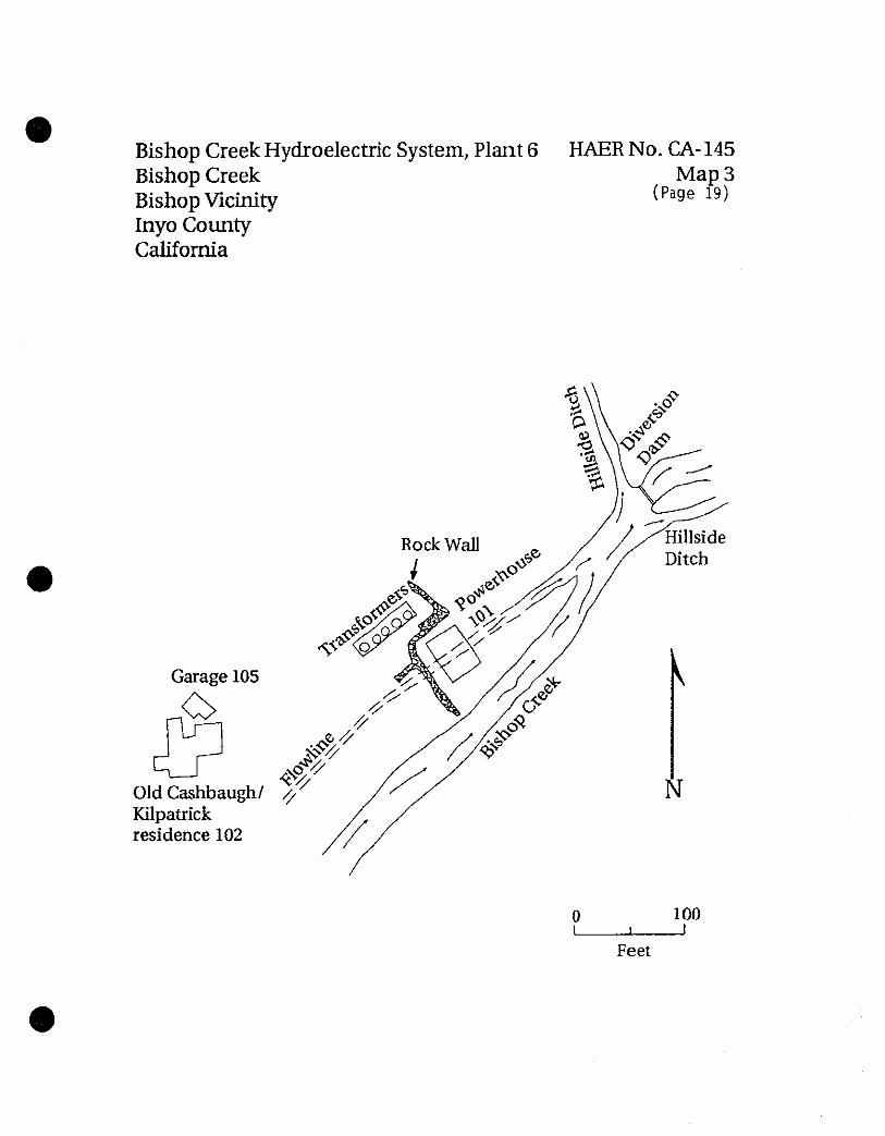
Map 3 shows the Plant 6 layout. Elements of the Historic District present at Plant 6 in 1994 are the Plant 6 powerhouse (Building 101), a small utility building on the east side of the Plant, the old Cashbaugh-Kilpatrick residence (Building 102), a garage associated with the residence (Building 105), and stone retaining walls around the powerhouse and circuit breakers. A small orchard and fenced sheep grazing plot adjoins the residence. The surrounding countryside is undeveloped and vegetated in Native species.
Photograph 145-6-2 shows a 1994 aerial view of the Plant 6 complex looking west; the powerhouse is at photo-center and the old Cashbaugh-Kilpatrick residence is adjacent. Photograph 145-6-3 shows a ground-level view looking west at the Plant 6 powerhouse with the old Cashbaugh-Kilpatrick residence in the background. Photograph 145-6-4 shows a ground-level view looking east at the old Cashbaugh-Kilpatrick residence with the powerhouse in the right background.
Plant 5. Plant 5 was constructed by the Nevada-California Power Company in 1907. It was the second generating plant built on the Bishop Creek System, and is located on the stream between Plants 4 and 6. Built in the Utilitarian/Early 20th Century Industrial style, Plant 5 is the only powerhouse structure on the System constructed with a steel framework. (All other plant structures utilized reinforced concrete for basic wall support). Plant 5 is rectangular-in-
•
BISHOP CREEK HYDROELECTRIC SYSTEM HAER No. CA-145 (Page 8) BISHOP CREEK BISHOP VICINITY INYO COUNTY CALIFORNIA
plan with a steeply pitched roof and roof monitor. The exterior walls axe composed of corrugated sheet-metal. A 19 foot by 38 foot shed-roofed addition was built in 1919. The powerhouse contains two water wheels and two generators.
In March 1912, Plant 5 was sold to the Southern Sierras Power Company. This company was created to finance the other developments of the Bishop Creek Hydroelectric System needed to transmit power to Southern California.
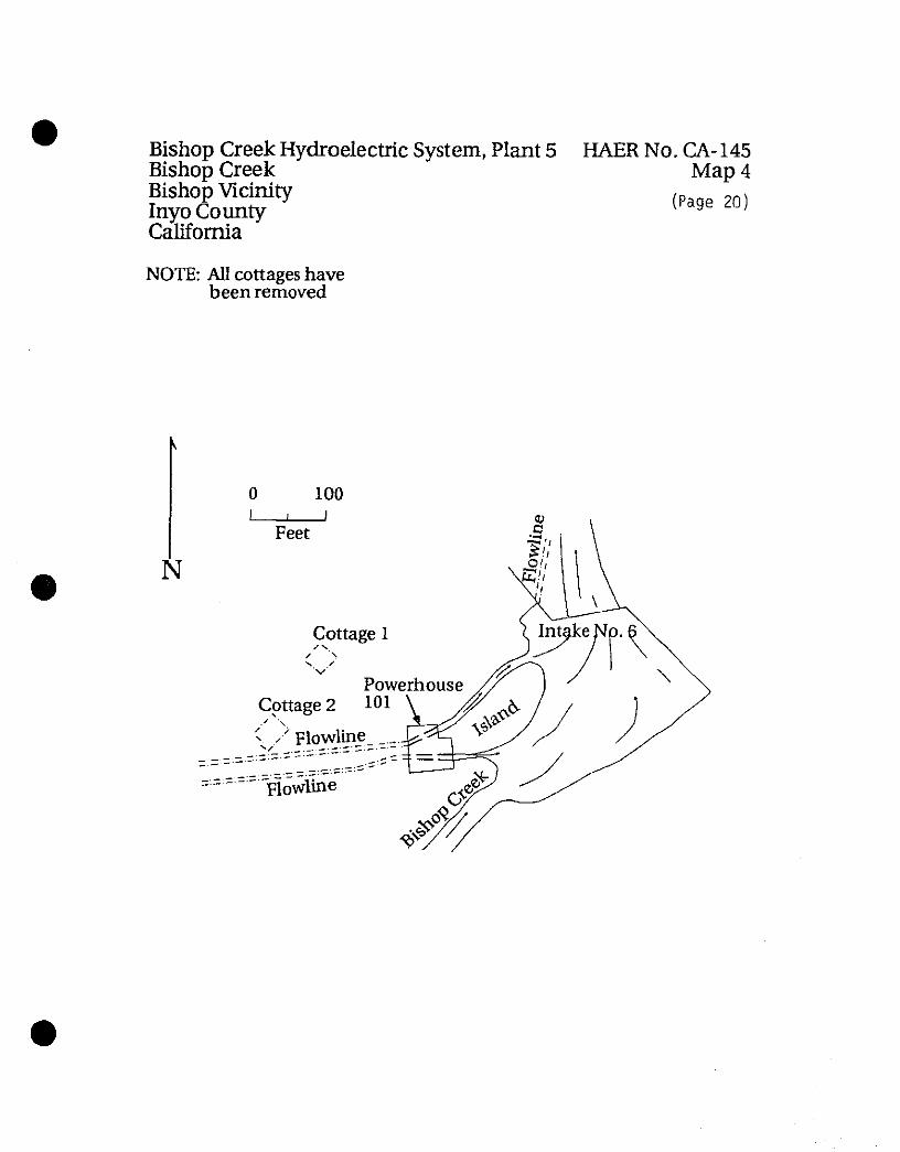
Map 4 shows the layout of the Plant 5 complex. At one time, the Plant 5 complex consisted of the powerhouse (Building 101) and two worker cottages. The cottages were located adjacent to the powerhouse on the northwest side. They were removed in the late 1970s. Stone retaining walls define the former location of these structures. Other than the nearby Control Station, the landscape surrounding Plant 5 is undeveloped and vegetated in Native species.
Photograph 145-5-1 is a ca. 1950 view of the powerhouse north side elevation and one of the two tailraces. The 1919 shed addition to the powerhouse shows prominently, as does the original three phase outdoor transformer. Photograph 145-5-2 is a 1994 view west at the Plant 5 powerhouse looking across the Plant 6 intake. Stone retaining walls visible behind the powerhouse delineate the former cottage locations. Photograph 145-5-3 is a 1994 aerial view to the east showing Plant 5 on the right adjacent to Bishop Creek; at photo-center is the Control Station complex.
Control Station. Prior to 1918, Bishop Creek Plants 2, 3, and 4 were operated by the Nevada- California Power Company who serviced the Nevada mining districts; Plants 5 and 6 were operated by the Southern Sierras Power Company, delivering power to Southern California. These two companies produced power at slightly different voltages, which meant they could not easily tie into each other. During this initial period, Control Station was the operational headquarters for the Southern Sierras Power Company facilities. After 1918, the two systems were permanently interconnected and a new, larger Control Station was built to manage the power resources of the combined System.
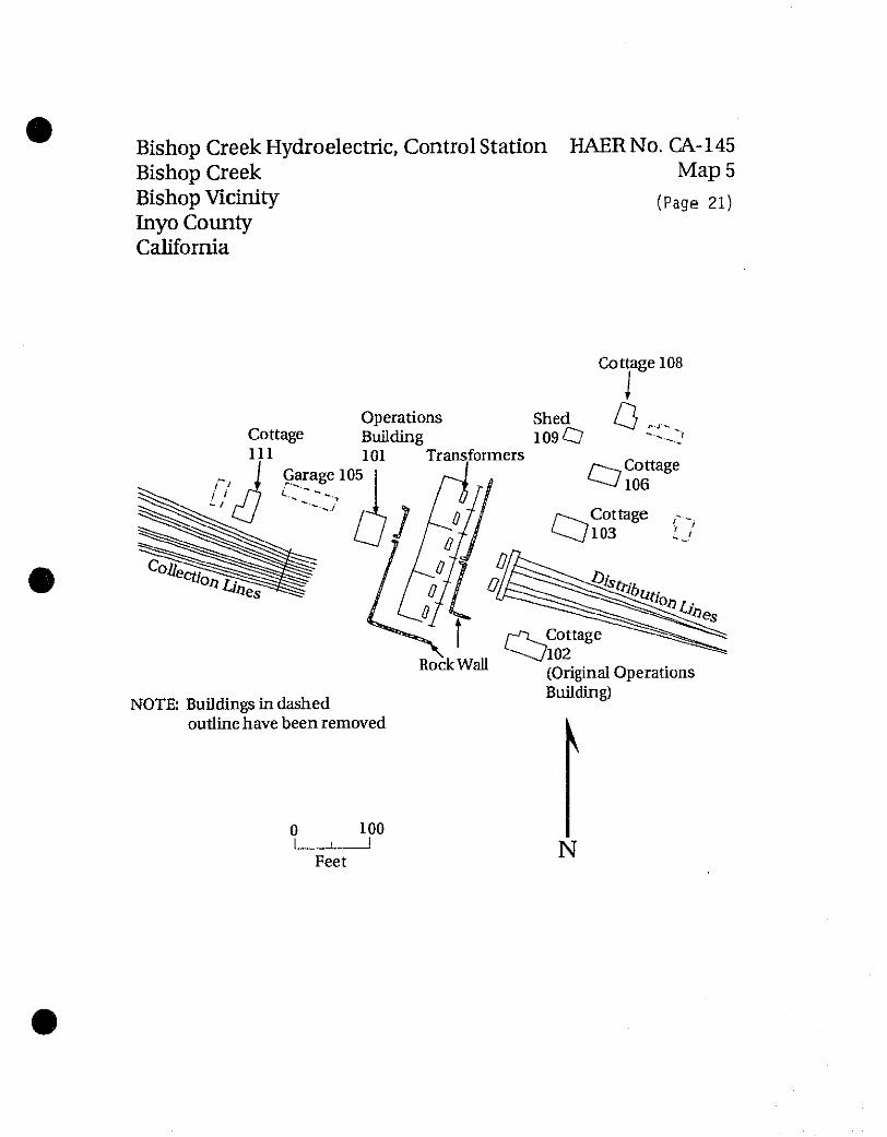
Control Station initially consisted of an operations building, a substation and switching equipment, and six cottages. When the new Control Station was built in 1919, the old operations building was converted to a worker residence. Edison drawings show that after 1923, Control Station consisted of the new Control building, a substation and switching equipment, and five worker residences distributed differently than before; this layout is show on Map 5.
BISHOP CREEK HYDROELECTRIC SYSTEM BISHOP CREEK BISHOP VICINITY INYO COUNTY CALIFORNIA
HAER No. CA-145 (Page 9)
In February 1994, Control Station consisted of the operations building (building 101), houses 102 (the original operation building), 103, 106, 108, and 111, and a garage (building 109). A garage (building 105) was removed in January 1994; this structure was a non-contributing element of the Historic District. Both the original operations building (building 102) and the present operations building (building 101) were built in the Mission Revival style. After building 102 was converted to a residence, the front hipped-roof porch was enclosed, and the north side elevation was modified by the addition of a small shed structure. Houses 103 and 106 are built in the Craftsman Bungalow style; house 108 is built in the Period Revival style; and house 111 is built in a style with Utilitarian/Craftsman influences. Beyond the immediate Control Station area, and other than the nearby Plant 5, the landscape is undeveloped and vegetated in Native species.
Photograph 145-1-1 is a ca. 1959 view of the 1919 Control Station operations building (building 101); the view is of the front, or east end facade. The building in the left background no longer exists, and that location is taken by switchracks. Photograph 145-1-2 is a 1994 southern view of the operations building, a 1980s construction telecommunications building adjacent west of the operations building, and (right background) cottage 111 (presently used as the hydrographer's office). Photograph 145-1-3 is a 1994 view to the southwest down the row of worker residences on the east side of Control Station; from right to left, the cottages are 108, 106, 103, and 102. Switchracks are visible behind the cottages. Photograph 145-1-4 is a 1994 view to the west showing the front of the Control Station complex; right to left, cottages 106, 103 and 102 are visible.
Plant 4. Constructed in 1904-05 by the Nevada Power, Mining and Milling Company, Plant 4 was the first of the Bishop Creek System. It has functioned from the outset as the operational headquarters of the System with the largest assortment of support buildings and the largest community of worker housing.
The Plant 4 powerhouse is built in the Utilitarian/Early 20th Century Industrial style. This structure is one and one-half stories, originally L-shaped in plan, built of reinforced concrete with steel roof trusses housing two generators and two water wheels. A monitor runs the length of the steeply-pitched roof. Two additional generating units were added shortly after construction, and in 1908 the building was expanded into a T-shape by an extension which housed additional transformers and a fifth water wheel and generator. A shed-roof addition and a flat-roofed addition were added between 1913 and 1928. These additions were expanded again in 1965.
BISHOP CREEK HYDROELECTRIC SYSTEM HAER No. CA-145 (Page 10) BISHOP CREEK BISHOP VICINITY INYO COUNTY CALIFORNIA
An overall chronology of the Plant 4 complex is difficult to construct because this place has been the site of intensive change. Residential and support structures have been built, rebuilt, removed, and others brought in. A total of forty one buildings were present at Plant 4 in 1994.
The recreation hall (originally the electrical substation structure), two vaults (lightning arrester building and meter house), and a valve house date to 1907. A garage used originally as a stave warehouse dates to around 1900. Four of the residential buildings date at least in part to 1909; seven are late 1920s construction. Most of the residential structures have been modified several times, and one was moved from another location. The present administration building was built in 1959; five other support buildings date from the 1950s as do most of the garages. Two support buildings were constructed in the 1980s, and two others were 1907 structures that were moved to their present location and then completely rebuilt in the 1970s.
Architectural styles of the residential structures at Plant 4 suggest at least two periods of construction. Cottages 102, 103, 104, 105, 106, 113, and 114 are built in the Craftsman Bungalow style; cottages 115, 116, 117, 121, and 122 are built in the Period Revival style. Other architectural styles of contributing structures include Utilitarian/Early 20th Century Industrial (recreation hall [former electrical substation], building 109), Utilitarian (transformer vault [former meter house], building 126; valve house, building 127; and the fire hydrant house, building 128), Simplified Mission Revival (lightning arrestor vault, building 125), Late 19th Century Utilitarian (garage [former stave warehouse], building 130), and Utilitarian/Craftsman Influence (storage shed [former stave warehouse], building 135).
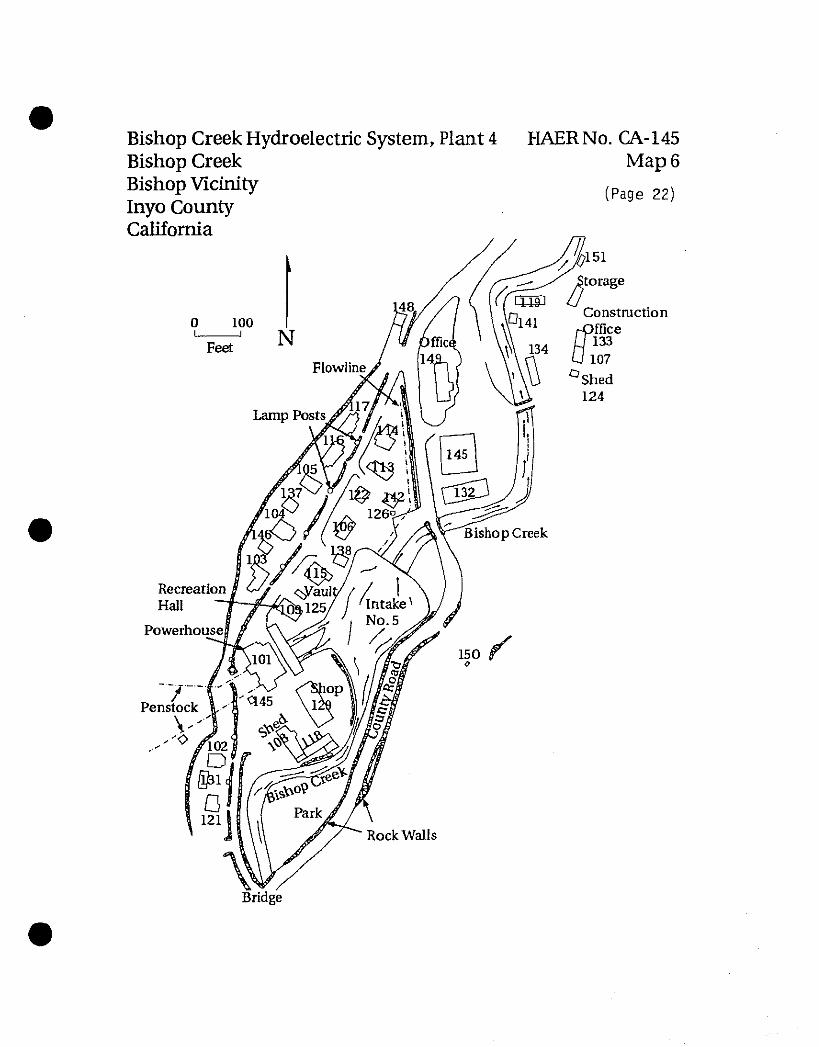
Plant 4 is situated in a wider spot in the lower reaches of the narrow Bishop Creek Canyon. Because of the confined space, the plant layout is elongated northeast/southwest along Bishop Creek, as shown in photograph 145-4-1 (a 1994 aerial view), and on Map 6. Most of the modern support buildings are located in the northeast quarter of the complex; a 1951 vintage shop building and two sheds (ca. 1927 and 1917) are located adjacent to the powerhouse on the south side. The powerhouse sits in the southwestern third of the complex. The residences and other buildings are distributed along both sides of a main northeast/southwest trending street which runs behind the powerhouse. Stone retaining walls define the west side of this street and contain the slope behind the houses on the west side. South of the powerhouse, residences occupy only the western side of the street which is bordered on the east in this area by Bishop Creek. South of the powerhouse, a small park occupies the triangle formed by Bishop Creek and the Old County Road which passes between the support building in the north and the residential community on its way to Plant 3 (photograph 145-4-2).
BISHOP CREEK HYDROELECTRIC SYSTEM HAER No. CA-145 (Page 11) BISHOP CREEK BISHOP VICINITY INYO COUNTY CALIFORNIA
Distinctive landscape features of the Plant 4 complex include leveling of the site and construction of terraces for the residential housing, and lawns and gardens around the residences. These are shown in photograph 145-4-3, a 1994 view to the southwest from the north end of the main residential street. Three stone wall designs are present. One type uses large quantities of exposed concrete with raised and tooled mortar joints between small exposures of rubble stone, such as that shown in photograph 145-4-4 (cottage 115 at left photo-center). Another retaining wall type has relatively uniform mortar joints using flat-faced rubble stone carefully broken and fitted together, such as that shown on the left side of photograph 145-4-5 lining the bank of Bishop Creek as it passes under the County Road bridge at the southern end of the residential area. The third type uses a facing of rounded river cobblestones. The main residential street has a uniform street-lighting system running along the western retaining wall (seen in photographs 145-4-4 and 145-4-5). The light structures consist of pedestal-mounted globe lights mounted on five-foot tall square shafts finished with rough stucco. The head of the shaft is covered by a square-based metal casting. The light fixtures appear to be predominately fabricated from wrought iron which incorporates curved metal straps with an iron base featuring simulated hand-forged spike heads. An internally lit, large globe of white opaque glass is the source of light. The retaining walls and street-light fixtures complement the powerhouse and residential buildings, and help to integrate the facility.
Photograph 145-4-6 show Bishop Creek and cottages 121 and 102, and garage 131 at photo- center. Photograph 145-4-7 shows (left to right) cottages 104, 105, 116, 117, and 115. Photograph 145-4-8 shows the Plant 4 complex from the eastern ridge; the powerhouse and residential area are in the left center, the operations buildings are in the center and right.
A ca. 1909 photograph of the Plant 4 complex is shown in photograph 145-4-9. In addition to the powerhouse and substation building (later the recreation hall), cottages 102, 104, and 105 are visible. A distinctive element of the early Plant 4 complex was the club house (photograph 145-4-10 and 145-4-11), located at the southern end of the residential area near the County Road bridge. This building was later modified by the addition of a second story (photograph 145-4-11), and eventually removed altogether. The lot where it stood is presently vacant.
Plant 3. Plant 3 was built by the Southern Sierras Power Company in 1913. It was the fourth plant put into operation in the System (plants 2, 4, and 5 preceded).
At one time, the Plant 3 complex was comprised of five cottages, two garages, a duplex (apartment building), the powerhouse, and a battery house. Map 7 shows the layout of this
BISHOP CREEK HYDROELECTRIC SYSTEM HAER No. CA-145 (Page 12) BISHOP CREEK BISHOP VICINITY INYO COUNTY CALIFORNIA
arrangement. The powerhouse and the battery house remain in operation. The other structures were removed in 1978 and 1979.
The powerhouse and the battery house were both built in 1913 utilizing the Mission Revival style. The powerhouse is a two-story reinforced-concrete structure housing three water wheels/generator assemblies. It was modified in 1954 by construction of a one story addition housing the control room. The battery house was originally a water valve house that served in conjunction with the penstocks. It was divided into two rooms before 1922, one continuing to serve as the valve house and the other a a shop room. The valve was removed in 1937 and in 1939 the shop was converted to a battery room.
Like Plants 4 and 2, Plant 3 is nestled next to Bishop Creek deep in the canyon. Other that the facilities associated with the System and Highway 168, no development is present in this area. The landscape is vegetated in the transitional native species typical of the eastern slopes of the Sierra Nevada Mountains.
Photograph 145-3-1 shows a view of the Plant 3 powerhouse in 1959; cottages 1 and 2 are visible behind the trees at photo-left. Photograph 145-3-2 is a 1994 repeat of the same view shown in photograph 145-3-1. Photograph 145-3-3 is a 1994 aerial view of Plant 3 from the same direction as photographs 145-3-1 and 145-3-2.
Plant 2.
Plant 2 was built by the Nevada-California Power Company in 1908. It was the third power plant to be built in the Bishop Creek System, having been preceded by Plants 4 and 5. It is the furthest plant on the System upstream and the highest in elevation (7,099 feet).
Four structures comprise the present Plant 2 complex. The powerhouse (building 101) and transformer house (building 106) were both built in 1908 utilizing the Mission Revival style. The powerhouse is a two-story reinforced concrete structure housing three water wheels and generators; a one story addition to the powerhouse was built in 1927 in style with the main building. Numerous fenestration changes have been applied to the powerhouse and transformer building over the years. In the powerhouse building, these changes left openings with dimensions generally consistent with the original. In the transformer building, the changes have primarily taken the form of closing up original door and window openings. A small asbestos-shingled shed (building 107), built in 1910, and a relatively modern garage (building 111) complete the Plant 2 complex.
BISHOP CREEK HYDROELECTRIC SYSTEM HAER No. CA-145 (Page 13) BISHOP CREEK BISHOP VICINITY INYO COUNTY CALIFORNIA
Four cottages once were associated with the complex. Map 8 shows the early Plant 2 layout. Photographs 145-2-4 and 145-2-5 with views west of pre-1970 age show the complex with the cottages. A large orchard comprised the landscaping associated with cottage 4 south of the powerhouse. Extensive stone retaining walls remain from the former residential areas. These cottages were removed in 1978-79.
Photograph 145-2-6 is a 1994 repeat of photograph 145-2-5; the absence of the diamond- shaped windows on the transformer building is especially noticeable. Photograph 145-2-1 is an aerial view of the narrow Plant 2 canyon context. Photograph 145-2-2 is an aerial view from the opposite angle from photograph 145-2-1; the Plant 3 flowline is clearly visible departing Plant 2. Photograph 145-2-3 is a view looking up the Plant 3 flowline toward Plant 2. This section of flowline is the last remaining of wood-stave construction (the other flowlines have been converted to metal); the ice hanging from the flowline are frozen leaks.
PART n. HISTORICAL CONTEXT - DEVELOPMENT OF THE BISHOP CREEK SYSTEM AND THE ELECTRIC POWER MARKETS OF WESTERN NEVADA AND SOUTHEASTERN CALIFORNIA
Word of the discovery of economic minerals at Tonopah and Goldfield in western Nevada drew numerous fortune seekers including, in 1904, Loren B. Curtis, an hydraulic engineer, and Charles M. Hobbs, a former official of the Denver and Rio Grande Railway. Curtis and Hobbs had come for the mineral prospects, but realized that the economic boom could not continue without adequate power (Myers 1983:69). Although the locally owned and operated Tonopah Light and Power Company and Goldfield Electric Light and Power Company had generated electricity by the burning of fuels, their power was too expensive and unreliable. Curtis and Hobbs recognized the potential market for hydroelectric power and identified Bishop Creek as the best location for the generators.
The Nevada Power, Mining and Milling Company was incorporated on 24 December 1904. Construction began on the first power plant (Plant 4) in January 1905. A contract for delivery of power was signed with the Combination Mines Company in May 1905. By August 1905 water rights had been secured from the Hillside Water Company, and on 19 September 1905 hydroelectric power was delivered to Goldfield Substation, and two days later to Tonopah.
System additions were undertaken in 1906-07 after new ore discoveries in Manhattan, Bullfrog, and Rhyolite, Nevada portended an expanding power market. These included an enlarged South Lake, a new reservoir on the Middle Fork Bishop Creek (Lake Sabrina), a new transmission line to Tonopah and Goldfield, a new general office in Goldfield, and expansion
BISHOP CREEK HYDROELECTRIC SYSTEM HAER No. CA-145 (Page 14) BISHOP CREEK BISHOP VICINITY INYO COUNTY CALIFORNIA
of Plant 4. In addition, the Nevada Power, Mining and Milling Company reorganized as the Nevada-California Power Company, and all capital stock of Hillside Water Company was purchased in order to guarantee adequate water supplies for electric power generation and permit the construction of additional plants along the course of Bishop Creek.
In 1908-09, the Nevada-California Power Company purchased the assets of the Bishop Light and Power Company and the capital stock of the Rhyolite Light, Heat and Power Company. Another unit was added to the Plant 4 powerhouse, and Plant 2 (1908) and Plant 5 (1909) were constructed. The existing facilities were now capable of producing twice the power for which there was a market.
In 1910, the Nevada-California Power Company decided to diversify their market by expanding into Southern California. In June 1911, the Southern Sierras Power Company was formed for this purpose. It purchased and operated the equipment installed at Plant 5, and began construction on a transmission line from Plant 5 to San Bernardino, California. Also in 1911, Plant 3 was built by the Nevada-California Power Company.
In 1913, the Southern Sierras Power Company completed construction of Plant 6 on lands downstream from Plant 5 and the System was essentially complete. (Plant 1 was to have been built at the present site of the Plant 2 intake, but the plant was never built because of the vulnerability of the site to avalanches). The combined power from the Bishop Creek System was now 24,350 kw.
In 1914, the Nevada-California Electric Corporation was formed as a holding company for the associated companies. In addition to the Nevada-California Power Company and the Southern Sierras Power Company, the associated companies included the Sierras Construction Company, the Corona Gas and Electric Company, the Bishop Light and Power Company, the Interstate Telegraph Company, the Hillside Water Company, the Elsinore Electric Light Company, and the Barstow Utilities Company.
Bishop Creek Plants 2, 3, and 4 were operated by the Nevada-California Power Company who serviced the Nevada mining districts; Plants 5 and 6 were operated by the Southern Sierras Power Company, delivering power to Southern California. Prior to 1918, these two companies produced power at slightly different voltages, which meant they could not easily tie into each other. During this initial period, Control Station was the operational headquarters for the Southern Sierras Power Company facilities. After 1918, the two systems were permanently interconnected and a new, larger Control Station was built to manage the power resources of the combined System.

BISHOP CREEK HYDROELECTRIC SYSTEM HAER No. CA-145 (Page 15) BISHOP CREEK BISHOP VICINITY INYO COUNTY CALIFORNIA
In 1936, the Nevada-California Electric Corporation reorganized as an operating company and changed its name to the California Electric Power Company, or CalElectric. CalElectric was absorbed by the Southern California Edison Company in a merger/takeover in 1964.
The Bishop Creek System is significant for its position in the expansion of hydroelectric generation technology, its role in the development of southeastern California, and the development of long-distance power transmission and distribution. The System is credited with several early long-distance transmission records. In 1905, a high-voltage power line was put into operation between Bishop Creek and Tonopah and Goldfield, Nevada, a distance of 118 miles (Poole 1914:1045). In 1912, the "Tower Line/' built from Plant 5 to San Bernardino, a distance of 239 miles (another record), was completed and put into operation. The Tower Line's access road also became significant by greatly reducing automobile travel time across the western Mojave Desert; it became first a county road and finally federal Highway 395. Southern Sierras also won the contract to supply power for the construction of Hoover Dam (Boulder Dam) on the Colorado River in 1931, and constructed a new transmission line for this purpose. The Bishop Creek System contributed vitally to the success of the Tonopah and Goldfield mining ventures and the overall economic independence of eastern Nevada. And, along with the associated companies, Bishop Creek provided power to run large-scale ice producing machines in San Bernardino, Coachella, and Imperial Valleys. The ice was used to preserve farm products on their way to market, which greatly facilitated agricultural expansion in Coachella and Imperial Valleys.
PART m. PROJECT INFORMATION
Southern California Edison is undertaking the Eastern Automation Project, an endeavor designed to fully automate the small hydroelectric powerplants in Edison's Southern Hydro Division and provide for their remote operation. One element of that Project is the construction of a new operations building at Control Station. Although none of the contributing structures in the Bishop Creek Historic District will be directly affected by this new building, its presence will alter the historic context at Control Station. Mitigation for this impact is documentation of the Control Station context. This documentation effort was also viewed as an opportunity to capture the present historic context at plants 2, 3, 4, 5, and 6.
This work is especially timely because the improved access between the Bishop Creek facilities and the town of Bishop coupled with the changing manner in which the Bishop Creek System operates is inexorably moving Edison away from providing company housing. Already, company housing has been removed from Plants 2, 3 and 5, and only Plant 4 has a substantial
BISHOP CREEK HYDROELECTRIC SYSTEM HAER No. CA-145 (Page 16) BISHOP CREEK BISHOP VICINITY INYO COUNTY CALIFORNIA
community. It is anticipated that within the next ten years or so, company housing on the Bishop Creek System along with an associated way of life will disappear altogether.
PART IV. SOURCES OF INFORMATION
Primarily two documents were relied upon for the information in this record: Diamond et al. (1988), and Clerico and Koval (1986). These are exhaustive studies prepared for the Bishop Creek Hydroelectric System relicense application pending before the Federal Energy Regulatory Commission.
Clerico, Robert, and Ana Beth Koval 1986 An Architectural and Historical Evaluation of Structures Associated with the Bishop
Creek Hydroelectric Power System, Inyo County, California. Report to the Southern California Edison Company. Silver City, NV: Intermountain Research, Inc.
Diamond, Valerie H., Stephen G. Helmich, and Robert A. Hicks 1988 Evaluation of the Historic Resources of the Bishop Creek System. Report to the
Southern California Edison Company. Fair Oaks, CA: Theodoratus Cultural Research, Inc.
Fowler, Frederick Hall 1923 Hydroelectric Power Systems of California. United States Geological Survey, Water
Supply Paper No. 493. Washington, D.C.: Government Printing Office.
Myers, William A. 1983 Iron Men and Copper Wires: A Centennial History of the Southern California Edison
Company. Glendale: Trans-Anglo Books.
Poole, C. O. 1914 Hydroelectric Development on Bishop Creek, Cal.—VII. Electrical World, November
28, pp. 1045-47.
Bishop Creek Hydroelectric System, Bishop Creek Bishop Vicinity Inyo County California
HAERNo.CA-145 Map 1
(Page 17)
Canon Sink
50
MILES N
MANHATTAN ©
% LIDA *
% ( ^BRIDGEgORT
■ i , Yosemite ^N l-j National i
Park )
Mono Lake
% ®Qj^ SILVER £
TONOPAH
.DFIELD
© FRESNO
Bishop Creek Hydroelectric System, Bishop Creek Bishop Vicinity Inyo County California
HAERNo.CA-145 Map 2
(Page 18)
Penstocks CQpZROL a°*a™J,M/POWERHOUSE 6
Pennock5 &
Longley Lake
South Lake
Bishop Creek Hydroelectric System, Plant 6 Bishop Creek Bishop Vicinity Inyo County California
HAERNo.CA-145 Map 3
(Page 19)
Garage 105
Old Cashbaugh/ // Kilpatrick residence 102
«'
100
Feet
Bishop Creek Hydroelectric System, Plant 5 Bishop Creek Bishop Vicinity Inyo County California
HAERNo.CA-145 Map 4
(Page 20)
NOTE: All cottages have been removed
N
100 _l
Feet
Cottage 1 • \
Powerhouse Cottage 2 101
\ / Flowline _.=
""Flowfine
Bishop Creek Hydroelectric, Control Station HAERNo. CA-145 Bishop Creek Map 5 Bishop Vicinity (Page 2i) Inyo County California
Cottage 108
Operations Shed CJj r Cottage Building 109 O C^' 111 101 Transformers „ ^
n I Garage 105 ^ g ^Cottage
NOTE: Buildings in dashed outline have been removed
100
/-^Cottage r
Rock Wall (Original Operations Building)
V
Feet N
Bishop Creek Hydroelectric System, Plant 4 HAER No. CA-145 Bishop Creek Bishop Vicinity Inyo County California
Map 6
(Page 22)
Flowline
Lamp Posts
13£
Bishop Creek
Recreation Hall
Rock Walls
151
to rage
Construction rQffice
U 107 Shed 124
Bridge
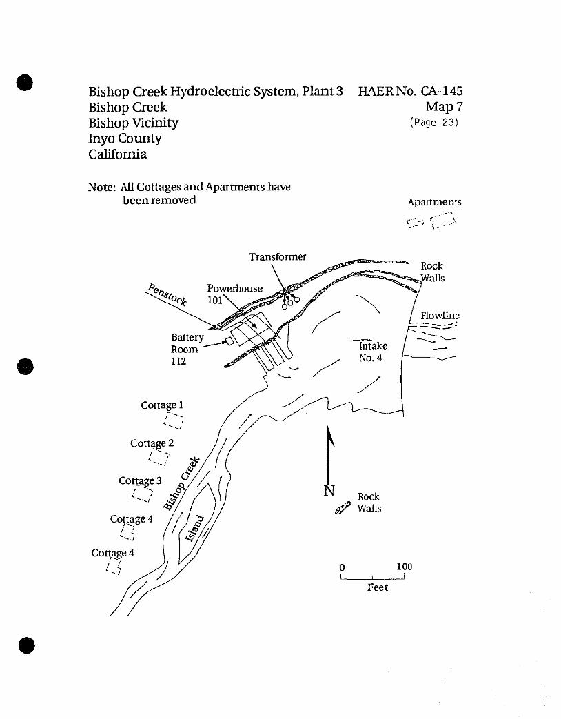
Bishop Creek Hydroelectric System, Plant 3 HAERNo. CA-145 Bishop Creek Map 7 Bishop Vicinity (Page 23) Inyo County California
Note: All Cottages and Apartments have been removed Apartments
Transformer
Rock jf Walls
Rock Walls
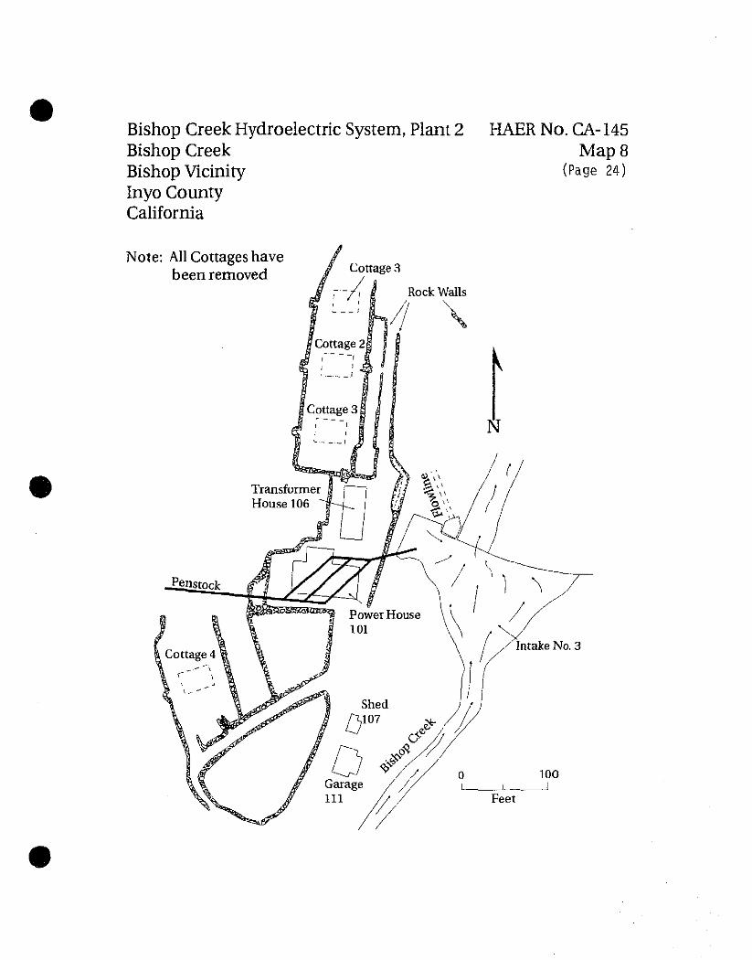
Bishop Creek Hydroelectric System, Plant 2 Bishop Creek Bishop Vicinity Inyo County California
HAERNo.CA-145 Map 8
(Page 24)
Note: All Cottages have been removed