Embed Size (px)
DESCRIPTION
service manual
Citation preview

SERVICE MANUAL
2010.052010.05Ver. 1.0Ver. 1.0

TRADEMARKSKONICA MINOLTA and the KONICA MINOLTA logo are trademarks or registered trademarks of KONICA MINOLTA HOLDINGS, INC.bizhub and PageScope are trademarks or registered trademarks of KONICA MINOLTABUSINESS TECHNOLOGIES, INC.Apple and Macintosh are trademarks of Apple Inc., registered in the United States and other countries.PCL is either a trademark or a registered trademark of Hewlett-Packard Company in the United States and other countries.Windows Vista is either a registered trademark or a trademark of Microsoft Corporation in the United States and/or other countries.Microsoft, Windows, Windows Server and Internet Explorer are registered trademarks of Microsoft Corporation in the United States and/or other countries.Linux is a registered trademark of Linus Torvalds in the United States and other countries.PostScript and PostScript3 are either registered trademarks or trademarks of Adobe Systems Incorporated in the United States and/or other countries.ENERGY STAR is a U.S. registered mark.Citrix and MetaFrame are registered trademarks of Citrix Systems, Inc. in the United States.Intel, Intel Xeon and Pentium are trademarks or registered trademarks of Intel Corporation.AMD, AMD Athlon, AMD Opteron and combinations thereof, are trademarks of Advanced Micro Devices, Inc.PictBridge is a trademark.Each company whose software title is mentioned in this manual has a Software License Agreement specific to its proprietary programs.All other trademarks are the property of their respective owners.The Fuji Xerox 4024 II is a registered trademark of Fuji Xerox.The Proprinter XL is a registered trademark of IBM.The FX-850 is a registered trademark of Epson.
© Copyright KONICAMINOLTA 2010
All rights reserved.No part of this publication may be reproduced in any form or by any means without permission in writing from the publisher.All other product and company names mentioned in this manual are trademarks or registered trademarks of their respective holders.Specifications are subject to change without notice.
i Confidential
PREFACE
This service manual contains basic information required for after-sales service of the Laser Multi-Function Center (hereinafter referred to as "the machine"). This information is vital to the service personnel to maintain the high printing quality and performance of the machine.
This service manual covers the bizhub 20 machines.
This manual consists of the following chapters:
CHAPTER 1: SPECIFICATIONSProvides specifications of each model, which enables you to make a comparison of the different models.
CHAPTER 2: THEORY OF OPERATIONGives an overview of the printing mechanisms as well as the sensors, actuators, and control electronics. It aids in understanding the basic principles of operations as well as locating defects for troubleshooting.
CHAPTER 3: ERROR INDICATION AND TROUBLESHOOTINGDetails of error messages and codes that the incorporated self-diagnostic function of the machine will display if any error or malfunction occurs. If any error message appears, refer to this chapter to find which parts should be checked or replaced.
The latter half of this chapter provides sample problems that could occur in the main sections of the machine and related troubleshooting procedures.
CHAPTER 4: PERIODICAL MAINTENANCEDetails of consumable parts and periodical maintenance parts. This chapter also covers procedures for disassembling and assembling periodical maintenance parts.
CHAPTER 5: DISASSEMBLY/REASSEMBLYDetails of procedures for disassembling and assembling of the machine together with related notes. The disassembly order flow provided enables you to see at a glance the quickest way to get to parts involved.
At the start of a disassembly job, you can check the disassembly order flow that guides you through a shortcut to get to the object parts.
This chapter also covers screw tightening torques and lubrication points to which the specified lubrications should be applied during assembly jobs.
CHAPTER 6: SERVICE FUNCTIONSDescribes the maintenance mode which is exclusively designed for the purpose of checking the settings and adjustments using the keys on the panel.
This chapter also covers hidden function menus, which activate settings and functions or reset the parts life.
CHAPTER 7: CIRCUIT DIAGRAMS, WIRING DIAGRAMProvides the Circuit Diagrams and Wiring diagram for the connections of the PCBs.
ii Confidential
APPENDIX 1: WORKER SWITCH (WSW)
APPENDIX 2: DELETION OF USER SETTING INFORMATION, etc.Provides instructions on how to delete such as user setting information recorded in the machine.
APPENDIX 3: SCREW CATALOGUE
APPENDIX 4: REFERENCES
APPENDIX 5: GLOSSARY
Information in this manual is subject to change due to improvement or redesign of the product.
A thorough understanding of this machine, based on information in this service manual, is required for maintaining its print quality performance and for improving the practical ability to find the cause of problems.
iii Confidential
REGULATION
For Europe and Other countriesRadio interference (220 to 240 volt model only)This machine follows EN55022 (CISPR Publication 22)/Class B.
Before you use this product, make sure that you use one of the following interface cables.
(1) A shielded parallel interface cable with twisted-pair conductors and that it is marked IEEE 1284 compliant.
(2) A USB cable.
The cable must not be more than 2 meters long.
IEC 60825-1 specification (220 to 240 volt model only)This machine is a Class 1 laser product as defined in IEC 60825-1 specifications. The label shown below is attached in countries where it is needed.
This machine has a Class 3B laser diode which produces invisible laser radiation in the laser unit. You should not open the laser unit under any circumstances.
CautionUse of controls or adjustments or performance of procedures other than those specified in this manual may result in hazardous radiation exposure.
For Finland and SwedenLUOKAN 1 LASERLAITEKLASS 1 LASER APPARAT
Varoitus!Laitteen käyttäminen muulla kuin tässä käyttöohjeessa mainitulla tavalla saattaa altistaa käyttäjän turvallisuusluokan 1 ylittävälle näkymättömälle lasersäteilylle.
VarningOm apparaten används på annat sätt än i denna Bruksanvisning specificerats, kan användaren utsättas för osynlig laserstrålning, som överskrider gränsen för laserklass 1.
CLASS 1 LASER PRODUCTLASER KLASSE 1 PRODUKTPRODUCTO LASER DE CLASE 1
iv Confidential
Internal laser radiation
Maximum radiation power: 5 mW
Wave length: 770 - 810 nm
Laser class: Class 3B
EU Directive 2002/96/EC and EN50419(European Union only)
This equipment is marked with the above recycling symbol. It means that at the end of the life of the equipment you must dispose of it separately at an appropriate collection point and not place it in the normal domestic unsorted waste stream. This will benefit the environment for all. (European Union only)
v Confidential
For USA and CanadaFederal Communications Commission (FCC) Declaration of Conformity (For USA)
Responsible Party: KONICA MINOLTA BUSINESS SOLUTIONS U.S.A., INC.100 Williams DriveRamsey, NJ 07446Phone: 201-825-4000
declares, that the products
Product name: bizhub 20
complies with Part 15 of the FCC Rules. Operation is subject to the following two conditions: (1) This device may not cause harmful interference, and (2) this device must accept any interference received, including interference that may cause undesired operation.
This equipment has been tested and found to comply with the limits for a Class B digital device, pursuant to Part 15 of the FCC Rules. These limits are designed to provide reasonable protection against harmful interference in a residential installation. This equipment generates, uses, and can radiate radio frequency energy and, if not installed and used in accordance with the instructions, may cause harmful interference to radio communications. However, there is no guarantee that interference will not occur in a particular installation. If this equipment does cause harmful interference to radio or television reception, which can be determined by turning the equipment off and on, the user is encouraged to try to correct the interference by one or more of the following measures:
• Reorient or relocate the receiving antenna.
• Increase the separation between the equipment and receiver.
• Connect the equipment into an outlet on a circuit different from that to which the receiver is connected.
• Consult the dealer or an experienced radio/TV technician for help.
ImportantA shielded interface cable should be used to ensure compliance with the limits for a Class B digital device. Changes or modifications not expressly approved by KONICAMINOLTA could void the user's authority to operate the equipment.
vi Confidential
Industry Canada Compliance Statement (For Canada)This Class B digital apparatus complies with Canadian ICES-003.
Cet appareil numérique de la classe B est conforme à la norme NMB-003 du Canada.
Laser Safety (110 to 120 volt model only)This machine is certified as a Class 1 laser product under the U.S. Department of Health and Human Services (DHHS) Radiation Performance Standard according to the Radiation Control for Health and Safety Act of 1968. This means that the machine does not produce hazardous laser radiation.
Since radiation emitted inside the machine is completely confined within protective housings and external covers, the laser beam cannot escape from the machine during any phase of user operation.
FDA Regulations (110 to 120 volt model only)The U.S. Food and Drug Administration (FDA) has implemented regulations for laser products manufactured on and after August 2, 1976. Compliance is mandatory for products marketed in the United States. The following label on the back of the machine indicates compliance with the FDA regulations and must be attached to laser products marketed in the United States.
Internal laser radiationMaximum radiation power: 5 mW
Wave length: 770 - 810 nm
Laser class: Class 3B
COMPLIES WITH 21CFR 1040.10 AND 1040.11 EXCEPT FOR DEVIATIONS PURSUANT TO LASER NOTICE NO.50, DATED JUNE 24, 2007.
vii Confidential
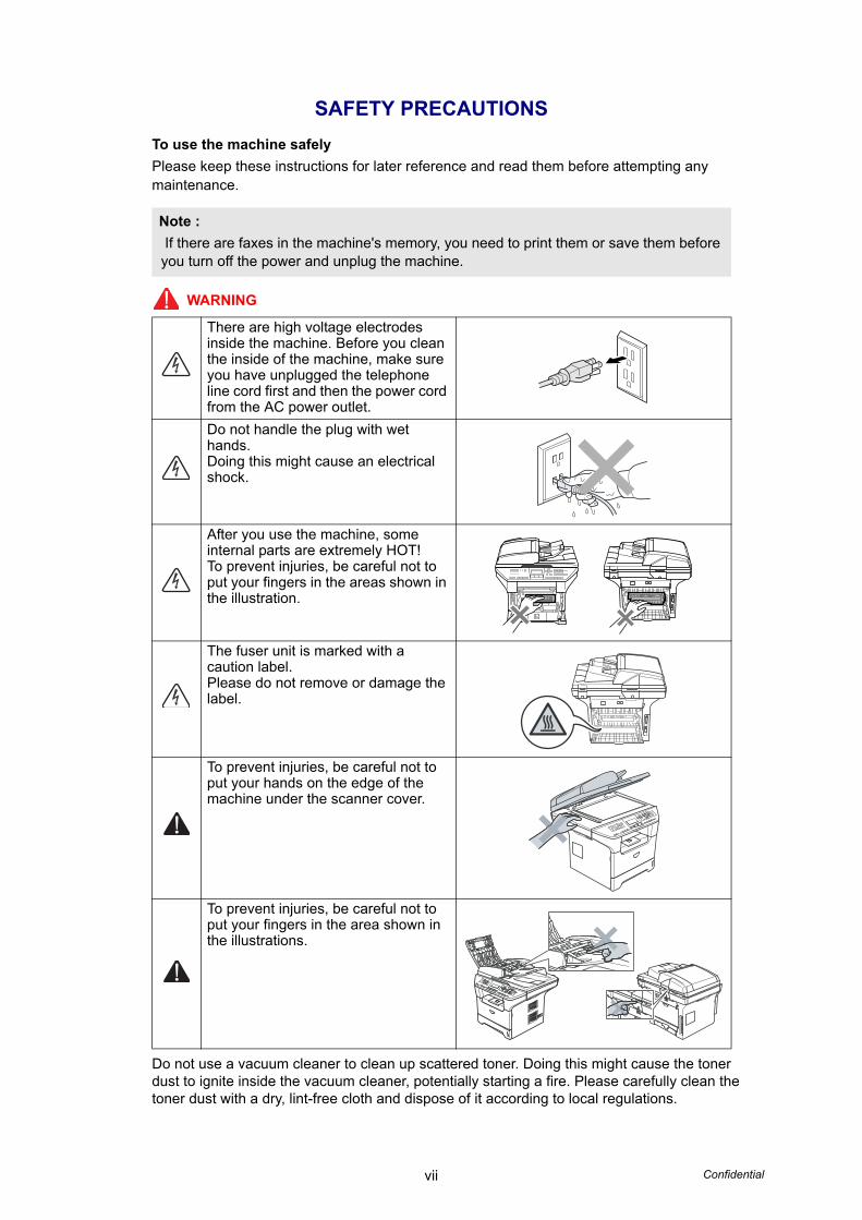
SAFETY PRECAUTIONSTo use the machine safelyPlease keep these instructions for later reference and read them before attempting any maintenance.
WARNING
Do not use a vacuum cleaner to clean up scattered toner. Doing this might cause the toner dust to ignite inside the vacuum cleaner, potentially starting a fire. Please carefully clean the toner dust with a dry, lint-free cloth and dispose of it according to local regulations.
Note : If there are faxes in the machine's memory, you need to print them or save them before you turn off the power and unplug the machine.
There are high voltage electrodes inside the machine. Before you clean the inside of the machine, make sure you have unplugged the telephone line cord first and then the power cord from the AC power outlet.Do not handle the plug with wet hands.Doing this might cause an electrical shock.
After you use the machine, some internal parts are extremely HOT!To prevent injuries, be careful not to put your fingers in the areas shown in the illustration.
The fuser unit is marked with a caution label.Please do not remove or damage the label.
To prevent injuries, be careful not to put your hands on the edge of the machine under the scanner cover.
To prevent injuries, be careful not to put your fingers in the area shown in the illustrations.
viii Confidential
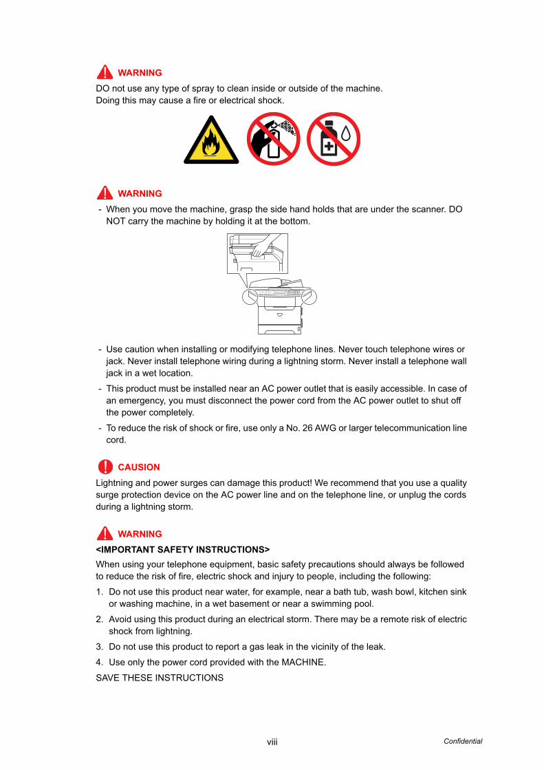
WARNINGDO not use any type of spray to clean inside or outside of the machine.Doing this may cause a fire or electrical shock.
WARNING- When you move the machine, grasp the side hand holds that are under the scanner. DO
NOT carry the machine by holding it at the bottom.
- Use caution when installing or modifying telephone lines. Never touch telephone wires or jack. Never install telephone wiring during a lightning storm. Never install a telephone wall jack in a wet location.
- This product must be installed near an AC power outlet that is easily accessible. In case of an emergency, you must disconnect the power cord from the AC power outlet to shut off the power completely.
- To reduce the risk of shock or fire, use only a No. 26 AWG or larger telecommunication line cord.
CAUSIONLightning and power surges can damage this product! We recommend that you use a quality surge protection device on the AC power line and on the telephone line, or unplug the cords during a lightning storm.
WARNING<IMPORTANT SAFETY INSTRUCTIONS>When using your telephone equipment, basic safety precautions should always be followed to reduce the risk of fire, electric shock and injury to people, including the following:
1. Do not use this product near water, for example, near a bath tub, wash bowl, kitchen sink or washing machine, in a wet basement or near a swimming pool.
2. Avoid using this product during an electrical storm. There may be a remote risk of electric shock from lightning.
3. Do not use this product to report a gas leak in the vicinity of the leak.
4. Use only the power cord provided with the MACHINE.
SAVE THESE INSTRUCTIONS
ix Confidential
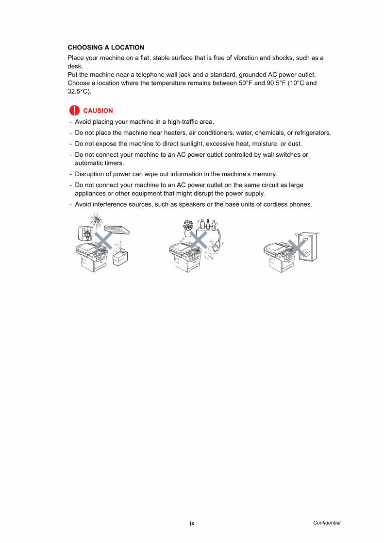
CHOOSING A LOCATIONPlace your machine on a flat, stable surface that is free of vibration and shocks, such as a desk.Put the machine near a telephone wall jack and a standard, grounded AC power outlet.Choose a location where the temperature remains between 50°F and 90.5°F (10°C and 32.5°C).
CAUSION- Avoid placing your machine in a high-traffic area.
- Do not place the machine near heaters, air conditioners, water, chemicals, or refrigerators.
- Do not expose the machine to direct sunlight, excessive heat, moisture, or dust.
- Do not connect your machine to an AC power outlet controlled by wall switches or automatic timers.
- Disruption of power can wipe out information in the machine’s memory.
- Do not connect your machine to an AC power outlet on the same circuit as large appliances or other equipment that might disrupt the power supply.
- Avoid interference sources, such as speakers or the base units of cordless phones.

CHAPTER 1SPECIFICATIONS
Confidential
CHAPTER 1 SPECIFICATIONS
This chapter lists the specifications of each model, which enables you to make a comparison of different models.
CONTENTS1. COMPONENTS.............................................................................................................1-1
2. SPECIFICATIONS LIST ................................................................................................1-2
2.1 Printing ..................................................................................................................1-2
2.2 Functions ...............................................................................................................1-3
2.3 Electronics and Mechanics....................................................................................1-6
2.4 Network Connectivity.............................................................................................1-7
2.5 Service Information................................................................................................1-8
2.6 Paper .....................................................................................................................1-9
2.6.1 Paper handling ...........................................................................................1-9
2.6.2 Media specifications .................................................................................1-10
2.6.3 Type and size of paper ............................................................................. 1-11
2.7 Printable Area......................................................................................................1-13
2.8 Print Speeds with Various Settings......................................................................1-19
2.9 Telephone............................................................................................................1-20
2.10 Fax.......................................................................................................................1-21
2.11 List/Report ...........................................................................................................1-23
2.12 Copy ....................................................................................................................1-24
2.13 Document Scanner..............................................................................................1-25
2.14 USB Host.............................................................................................................1-25
1-1 Confidential
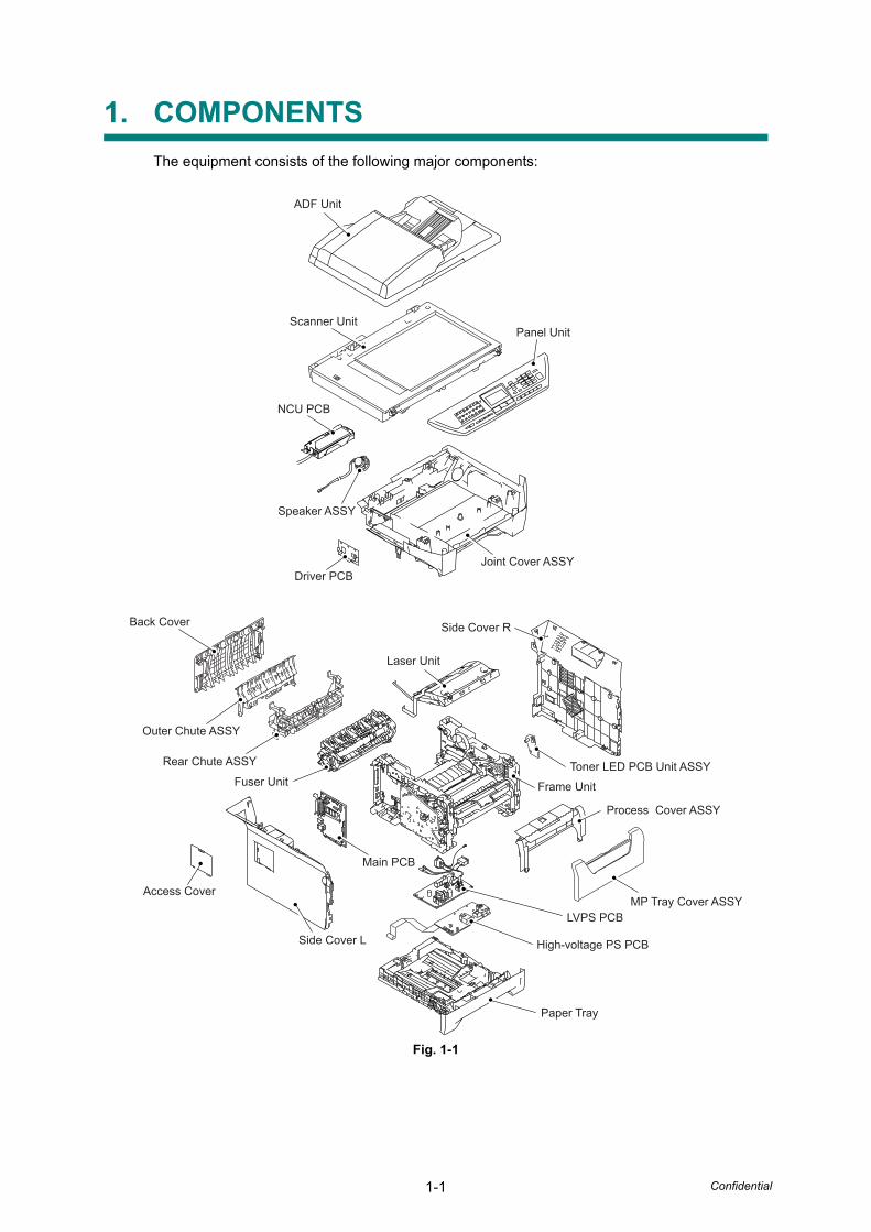
1. COMPONENTSThe equipment consists of the following major components:
Fig. 1-1
Driver PCBJoint Cover ASSY
NCU PCB
Scanner Unit
ADF Unit
Panel Unit
Speaker ASSY
Back Cover
Outer Chute ASSY
Rear Chute ASSY
Fuser Unit
Main PCB
Access Cover
Side Cover L
Side Cover R
Laser Unit
Toner LED PCB Unit ASSY
Paper Tray
High-voltage PS PCB
LVPS PCBMP Tray Cover ASSY
Process Cover ASSY
Frame Unit
1-2 Confidential
2. SPECIFICATIONS LIST
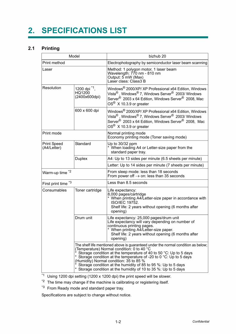
2.1 Printing
*1 Using 1200 dpi setting (1200 x 1200 dpi) the print speed will be slower.*2 The time may change if the machine is calibrating or registering itself.*3 From Ready mode and standard paper tray.
Specifications are subject to change without notice.
Model bizhub 20Print method Electrophotography by semiconductor laser beam scanningLaser Method: 1 polygon motor, 1 laser beam
Wavelength: 770 nm - 810 nmOutput: 5 mW (Max)Laser class: Class3 B
Resolution 1200 dpi *1, HQ1200 (2400x600dpi)
Windows® 2000/XP/ XP Professional x64 Edition, Windows Vista® , Windows® 7, Windows Server® 2003/ Windows Server® 2003 x 64 Edition, Windows Server® 2008, Mac OS® X 10.3.9 or greater
600 x 600 dpi Windows® 2000/XP/ XP Professional x64 Edition, Windows Vista® , Windows® 7, Windows Server® 2003/ Windows Server® 2003 x 64 Edition, Windows Server® 2008, Mac OS® X 10.3.9 or greater
Print mode Normal printing modeEconomy printing mode (Toner saving mode)
Print Speed(A4/Letter)
Standard Up to 30/32 ppm* When loading A4 or Letter-size paper from the
standard paper tray.Duplex A4: Up to 13 sides per minute (6.5 sheets per minute)
Letter: Up to 14 sides per minute (7 sheets per minute)
Warm-up time *2 From sleep mode: less than 18 secondsFrom power off → on: less than 35 seconds
First print time *3 Less than 8.5 seconds
Consumables Toner cartridge Life expectancy:8,000 pages/cartridge* When printing A4/Letter-size paper in accordance with
ISO/IEC 19752.Shelf life: 2 years without opening (6 months after opening)
Drum unit Life expectancy: 25,000 pages/drum unitLife expectancy will vary depending on number of continuous printing pages.* When printing A4/Letter-size paper.
Shelf life: 2 years without opening (6 months after opening)
The shelf life mentioned above is guaranteed under the normal condition as below;(Temperature) Normal condition: 0 to 40 °C* Storage condition at the temperature of 40 to 50 °C: Up to 5 days* Storage condition at the temperature of -20 to 0 °C: Up to 5 days(Humidity) Normal condition: 35 to 85 %* Storage condition at the humidity of 85 to 95 %: Up to 5 days* Storage condition at the humidity of 10 to 35 %: Up to 5 days
1-3 Confidential
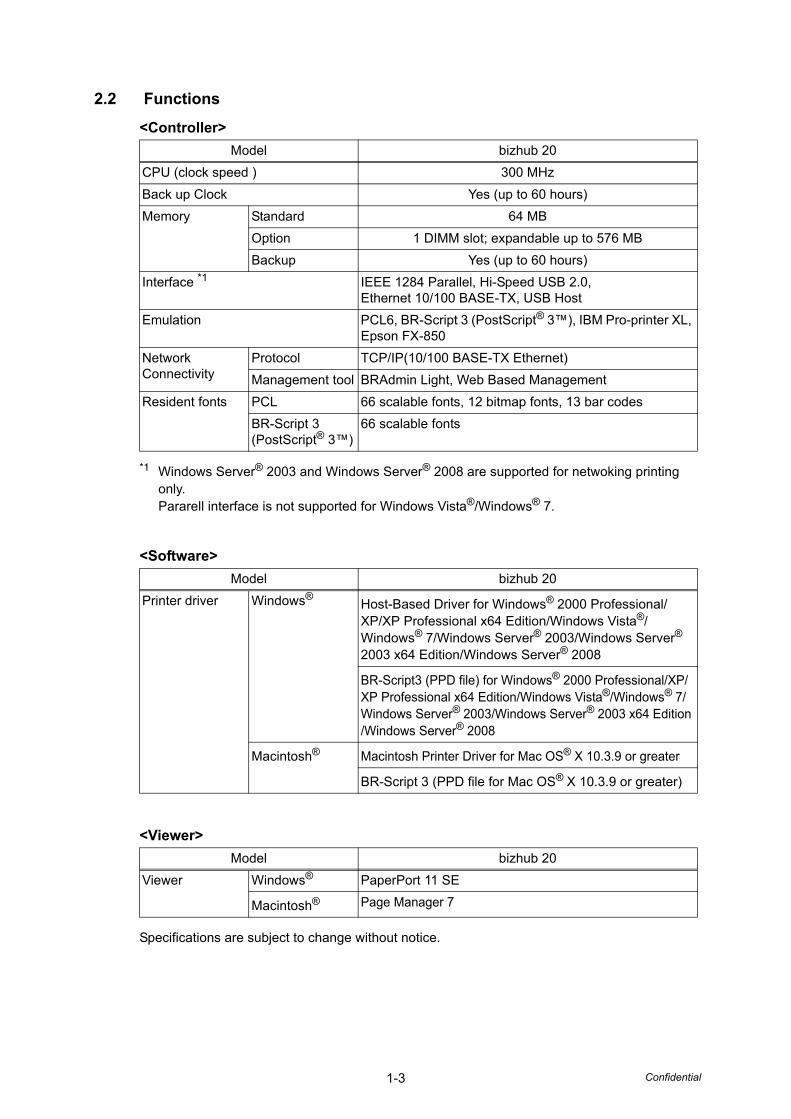
2.2 Functions
<Controller>
*1 Windows Server® 2003 and Windows Server® 2008 are supported for netwoking printing only.Pararell interface is not supported for Windows Vista®/Windows® 7.
<Software>
<Viewer>
Specifications are subject to change without notice.
Model bizhub 20CPU (clock speed ) 300 MHzBack up Clock Yes (up to 60 hours)Memory Standard 64 MB
Option 1 DIMM slot; expandable up to 576 MBBackup Yes (up to 60 hours)
Interface *1 IEEE 1284 Parallel, Hi-Speed USB 2.0, Ethernet 10/100 BASE-TX, USB Host
Emulation PCL6, BR-Script 3 (PostScript® 3™), IBM Pro-printer XL, Epson FX-850
Network Connectivity
Protocol TCP/IP(10/100 BASE-TX Ethernet)Management tool BRAdmin Light, Web Based Management
Resident fonts PCL 66 scalable fonts, 12 bitmap fonts, 13 bar codesBR-Script 3 (PostScript® 3™)
66 scalable fonts
Model bizhub 20Printer driver Windows®
Host-Based Driver for Windows® 2000 Professional/XP/XP Professional x64 Edition/Windows Vista®/Windows® 7/Windows Server® 2003/Windows Server® 2003 x64 Edition/Windows Server® 2008
BR-Script3 (PPD file) for Windows® 2000 Professional/XP/XP Professional x64 Edition/Windows Vista®/Windows® 7/Windows Server® 2003/Windows Server® 2003 x64 Edition /Windows Server® 2008
Macintosh® Macintosh Printer Driver for Mac OS® X 10.3.9 or greater
BR-Script 3 (PPD file for Mac OS® X 10.3.9 or greater)
Model bizhub 20Viewer Windows® PaperPort 11 SE
Macintosh® Page Manager 7
1-4 Confidential
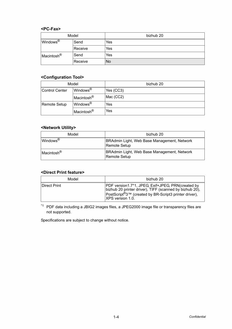
<PC-Fax>
<Configuration Tool>
<Network Utility>
<Direct Print feature>
*1 PDF data including a JBIG2 images files, a JPEG2000 image file or transparency files are not supported.
Specifications are subject to change without notice.
Model bizhub 20Windows® Send Yes
Receive Yes
Macintosh® Send YesReceive No
Model bizhub 20Control Center Windows® Yes (CC3)
Macintosh® Mac (CC2)
Remote Setup Windows® Yes
Macintosh® Yes
Model bizhub 20Windows® BRAdmin Light, Web Base Management, Network
Remote Setup
Macintosh® BRAdmin Light, Web Base Management, Network Remote Setup
Model bizhub 20Direct Print PDF version1.7*1, JPEG, Exif+JPEG, PRN(created by
bizhub 20 printer driver), TIFF (scanned by bizhub 20), PostScript®3™ (created by BR-Script3 printer driver), XPS version 1.0.
1-5 Confidential
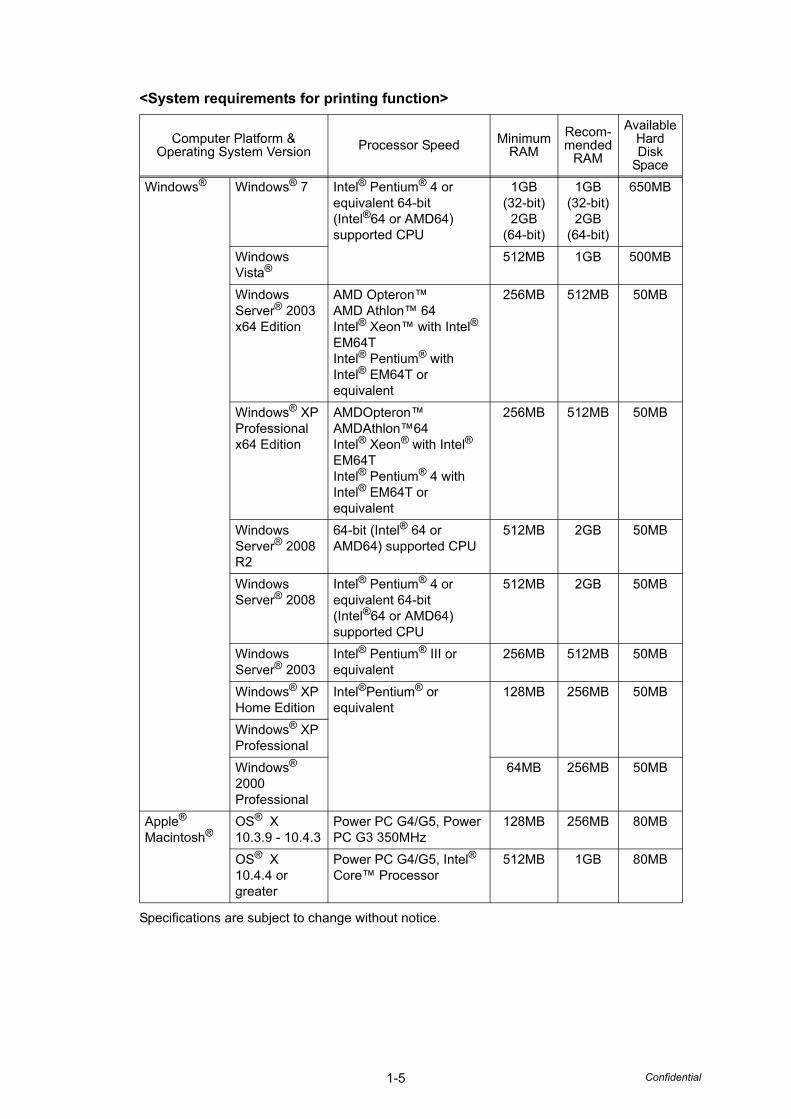
<System requirements for printing function>
Specifications are subject to change without notice.
Computer Platform & Operating System Version Processor Speed Minimum
RAMRecom-mended
RAM
Available Hard Disk
SpaceWindows® Windows® 7 Intel® Pentium® 4 or
equivalent 64-bit (Intel®64 or AMD64) supported CPU
1GB (32-bit)
2GB (64-bit)
1GB (32-bit)
2GB (64-bit)
650MB
Windows Vista®
512MB 1GB 500MB
Windows Server® 2003 x64 Edition
AMD Opteron™AMD Athlon™ 64Intel® Xeon™ with Intel® EM64TIntel® Pentium® with Intel® EM64T or equivalent
256MB 512MB 50MB
Windows® XP Professional x64 Edition
AMDOpteron™ AMDAthlon™64Intel® Xeon® with Intel® EM64TIntel® Pentium® 4 with Intel® EM64T or equivalent
256MB 512MB 50MB
Windows Server® 2008 R2
64-bit (Intel® 64 or AMD64) supported CPU
512MB 2GB 50MB
Windows Server® 2008
Intel® Pentium® 4 or equivalent 64-bit (Intel®64 or AMD64) supported CPU
512MB 2GB 50MB
Windows Server® 2003
Intel® Pentium® III or equivalent
256MB 512MB 50MB
Windows® XP Home Edition
Intel®Pentium® or equivalent
128MB 256MB 50MB
Windows® XP ProfessionalWindows® 2000 Professional
64MB 256MB 50MB
Apple®
Macintosh®OS® X10.3.9 - 10.4.3
Power PC G4/G5, Power PC G3 350MHz
128MB 256MB 80MB
OS® X10.4.4 orgreater
Power PC G4/G5, Intel® Core™ Processor
512MB 1GB 80MB
1-6 Confidential
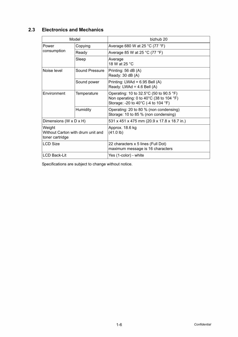
2.3 Electronics and Mechanics
Specifications are subject to change without notice.
Model bizhub 20Power consumption
Copying Average 680 W at 25 °C (77 °F)Ready Average 85 W at 25 °C (77 °F)Sleep Average
18 W at 25 °CNoise level Sound Pressure Printing: 56 dB (A)
Ready: 30 dB (A)Sound power Printing: LWAd = 6.95 Bell (A)
Ready: LWAd = 4.6 Bell (A)Environment Temperature Operating: 10 to 32.5°C (50 to 90.5 °F)
Non operating: 0 to 40°C (38 to 104 °F)Storage: -20 to 40°C (-4 to 104 °F)
Humidity Operating: 20 to 80 % (non condensing)Storage: 10 to 85 % (non condensing)
Dimensions (W x D x H) 531 x 451 x 475 mm (20.9 x 17.8 x 18.7 in.)WeightWithout Carton with drum unit and toner cartridge
Approx. 18.6 kg (41.0 lb)
LCD Size 22 characters x 5 lines (Full Dot)maximum message is 16 characters
LCD Back-Lit Yes (1-color) - white
1-7 Confidential
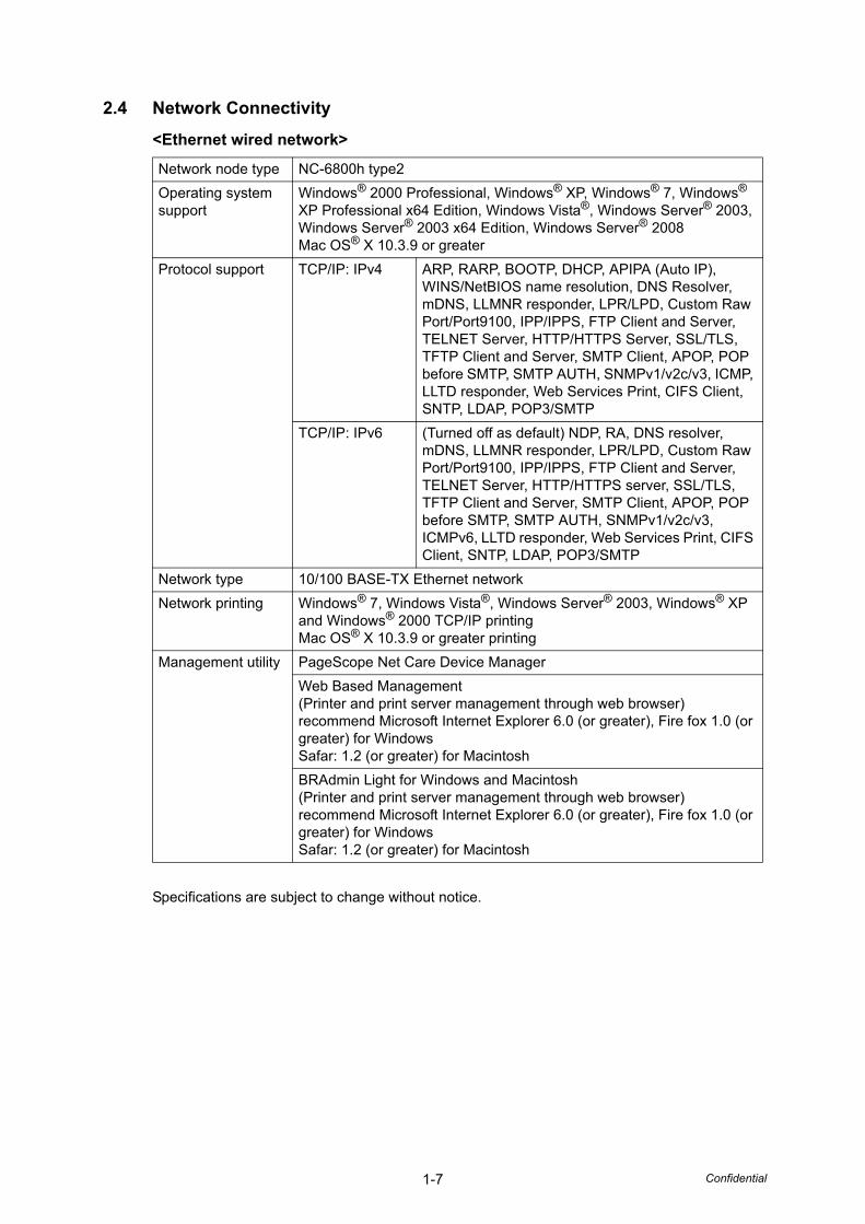
2.4 Network Connectivity
<Ethernet wired network>
Specifications are subject to change without notice.
Network node type NC-6800h type2Operating system support
Windows® 2000 Professional, Windows® XP, Windows® 7, Windows® XP Professional x64 Edition, Windows Vista®, Windows Server® 2003, Windows Server® 2003 x64 Edition, Windows Server® 2008Mac OS® X 10.3.9 or greater
Protocol support TCP/IP: IPv4 ARP, RARP, BOOTP, DHCP, APIPA (Auto IP), WINS/NetBIOS name resolution, DNS Resolver, mDNS, LLMNR responder, LPR/LPD, Custom Raw Port/Port9100, IPP/IPPS, FTP Client and Server, TELNET Server, HTTP/HTTPS Server, SSL/TLS, TFTP Client and Server, SMTP Client, APOP, POP before SMTP, SMTP AUTH, SNMPv1/v2c/v3, ICMP, LLTD responder, Web Services Print, CIFS Client, SNTP, LDAP, POP3/SMTP
TCP/IP: IPv6 (Turned off as default) NDP, RA, DNS resolver, mDNS, LLMNR responder, LPR/LPD, Custom Raw Port/Port9100, IPP/IPPS, FTP Client and Server, TELNET Server, HTTP/HTTPS server, SSL/TLS, TFTP Client and Server, SMTP Client, APOP, POP before SMTP, SMTP AUTH, SNMPv1/v2c/v3, ICMPv6, LLTD responder, Web Services Print, CIFS Client, SNTP, LDAP, POP3/SMTP
Network type 10/100 BASE-TX Ethernet networkNetwork printing Windows® 7, Windows Vista®, Windows Server® 2003, Windows® XP
and Windows® 2000 TCP/IP printingMac OS® X 10.3.9 or greater printing
Management utility PageScope Net Care Device ManagerWeb Based Management(Printer and print server management through web browser)recommend Microsoft Internet Explorer 6.0 (or greater), Fire fox 1.0 (or greater) for WindowsSafar: 1.2 (or greater) for MacintoshBRAdmin Light for Windows and Macintosh(Printer and print server management through web browser)recommend Microsoft Internet Explorer 6.0 (or greater), Fire fox 1.0 (or greater) for WindowsSafar: 1.2 (or greater) for Macintosh
1-8 Confidential
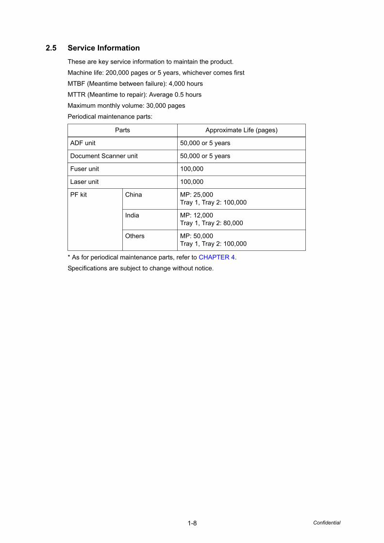
2.5 Service InformationThese are key service information to maintain the product.
Machine life: 200,000 pages or 5 years, whichever comes first
MTBF (Meantime between failure): 4,000 hours
MTTR (Meantime to repair): Average 0.5 hours
Maximum monthly volume: 30,000 pages
Periodical maintenance parts:
* As for periodical maintenance parts, refer to CHAPTER 4.
Specifications are subject to change without notice.
Parts Approximate Life (pages)
ADF unit 50,000 or 5 years
Document Scanner unit 50,000 or 5 years
Fuser unit 100,000
Laser unit 100,000
PF kit China MP: 25,000Tray 1, Tray 2: 100,000
India MP: 12,000Tray 1, Tray 2: 80,000
Others MP: 50,000Tray 1, Tray 2: 100,000
1-9 Confidential
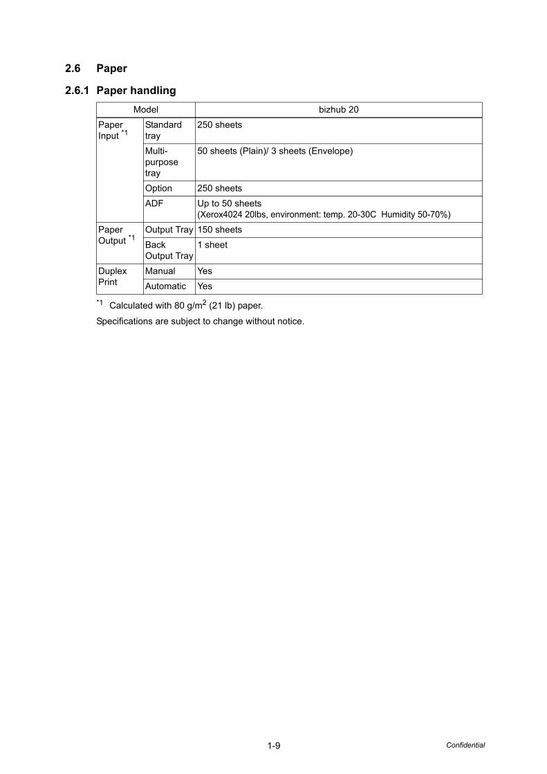
2.6 Paper
2.6.1 Paper handling
*1 Calculated with 80 g/m2 (21 lb) paper.
Specifications are subject to change without notice.
Model bizhub 20Paper Input *1
Standard tray
250 sheets
Multi-purpose tray
50 sheets (Plain)/ 3 sheets (Envelope)
Option 250 sheetsADF Up to 50 sheets
(Xerox4024 20lbs, environment: temp. 20-30C Humidity 50-70%)Paper Output *1
Output Tray 150 sheetsBack Output Tray
1 sheet
Duplex Print
Manual YesAutomatic Yes
1-10 Confidential
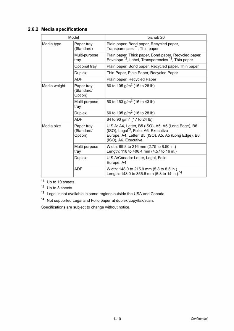
2.6.2 Media specifications
*1 Up to 10 sheets.*2 Up to 3 sheets.*3 Legal is not available in some regions outside the USA and Canada.*4 Not supported Legal and Folio paper at duplex copy/fax/scan.
Specifications are subject to change without notice.
Model bizhub 20Media type Paper tray
(Standard)Plain paper, Bond paper, Recycled paper, Transparencies *1, Thin paper
Multi-purpose tray
Plain paper, Thick paper, Bond paper, Recycled paper, Envelope *2, Label, Transparencies *1, Thin paper
Optional tray Plain paper, Bond paper, Recycled paper, Thin paperDuplex Thin Paper, Plain Paper, Recycled PaperADF Plain paper, Recycled Paper
Media weight Paper tray (Standard/Option)
60 to 105 g/m2 (16 to 28 lb)
Multi-purpose tray
60 to 163 g/m2 (16 to 43 lb)
Duplex 60 to 105 g/m2 (16 to 28 lb)ADF 64 to 90 g/m2 (17 to 24 lb)
Media size Paper tray (Standard/Option)
U.S.A: A4, Letter, B5 (ISO), A5, A5 (Long Edge), B6 (ISO), Legal*3, Folio, A6, ExecutiveEurope: A4, Letter, B5 (ISO), A5, A5 (Long Edge), B6 (ISO), A6, Executive
Multi-purpose tray
Width: 69.8 to 216 mm (2.75 to 8.50 in.)Length: 116 to 406.4 mm (4.57 to 16 in.)
Duplex U.S.A/Canada: Letter, Legal, FolioEurope: A4
ADF Width: 148.0 to 215.9 mm (5.8 to 8.5 in.)Length: 148.0 to 355.6 mm (5.8 to 14 in.) *4
1-11 Confidential
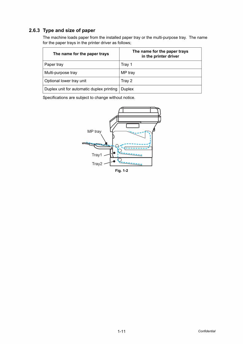
2.6.3 Type and size of paperThe machine loads paper from the installed paper tray or the multi-purpose tray. The name for the paper trays in the printer driver as follows;
Specifications are subject to change without notice.
Fig. 1-2
The name for the paper trays The name for the paper trays in the printer driver
Paper tray Tray 1
Multi-purpose tray MP tray
Optional lower tray unit Tray 2
Duplex unit for automatic duplex printing Duplex
Tray1
MP tray
Tray2
1-12 Confidential
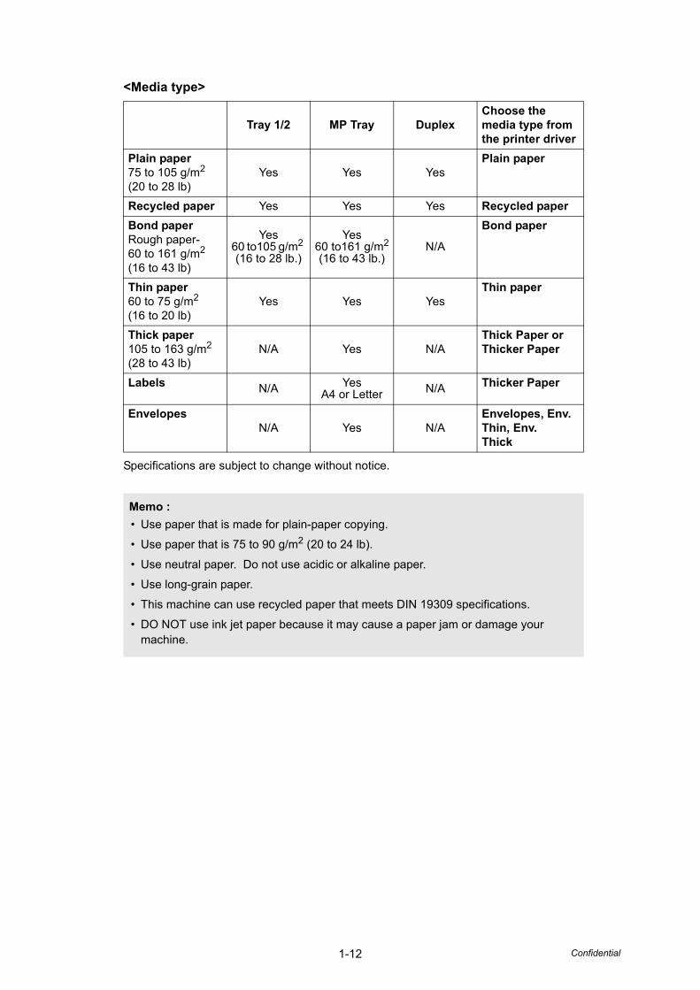
<Media type>
Specifications are subject to change without notice.
Tray 1/2 MP Tray DuplexChoose the media type from the printer driver
Plain paper75 to 105 g/m2
(20 to 28 lb)Yes Yes Yes
Plain paper
Recycled paper Yes Yes Yes Recycled paperBond paperRough paper-60 to 161 g/m2 (16 to 43 lb)
Yes60 to105 g/m2 (16 to 28 lb.)
Yes60 to161 g/m2
(16 to 43 lb.)N/A
Bond paper
Thin paper60 to 75 g/m2 (16 to 20 lb)
Yes Yes YesThin paper
Thick paper105 to 163 g/m2 (28 to 43 lb)
N/A Yes N/AThick Paper or Thicker Paper
Labels N/A YesA4 or Letter N/A Thicker Paper
EnvelopesN/A Yes N/A
Envelopes, Env. Thin, Env. Thick
Memo :• Use paper that is made for plain-paper copying.
• Use paper that is 75 to 90 g/m2 (20 to 24 lb).
• Use neutral paper. Do not use acidic or alkaline paper.
• Use long-grain paper.
• This machine can use recycled paper that meets DIN 19309 specifications.
• DO NOT use ink jet paper because it may cause a paper jam or damage your machine.
1-13 Confidential
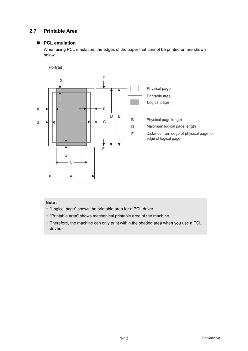
2.7 Printable Area
PCL emulationWhen using PCL emulation, the edges of the paper that cannot be printed on are shown below.
Note :• "Logical page" shows the printable area for a PCL driver.
• "Printable area" shows mechanical printable area of the machine.
• Therefore, the machine can only print within the shaded area when you use a PCL driver.
Portrait
A
B
C
D
E
F
GF
G
E
G G
Physical page
Printable areaLogical page
B Physical page length
D Maximum logical page length
F Distance from edge of physical page toedge of logical page
1-14 Confidential
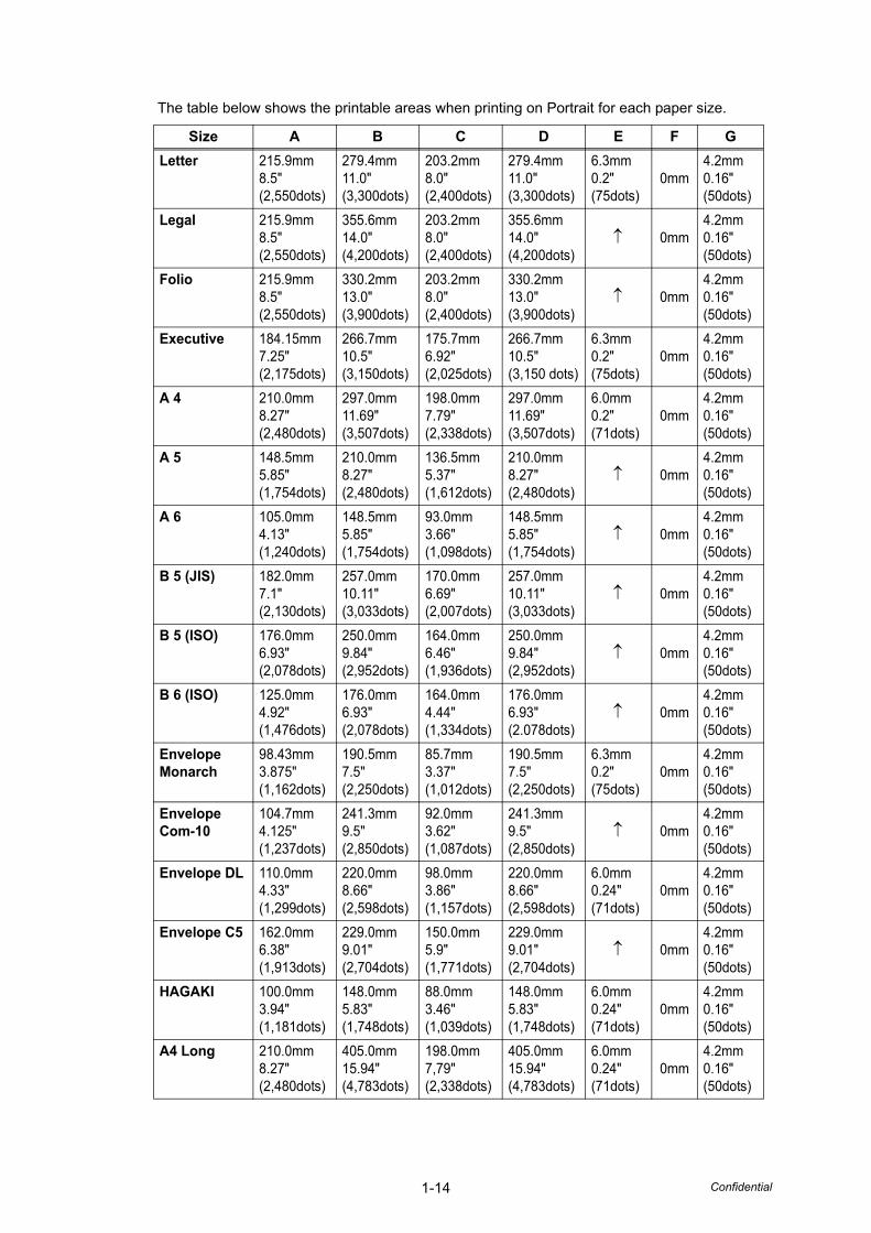
The table below shows the printable areas when printing on Portrait for each paper size.
Size A B C D E F GLetter 215.9mm
8.5"(2,550dots)
279.4mm11.0"(3,300dots)
203.2mm8.0"(2,400dots)
279.4mm11.0"(3,300dots)
6.3mm0.2"(75dots)
0mm4.2mm0.16"(50dots)
Legal 215.9mm8.5"(2,550dots)
355.6mm14.0"(4,200dots)
203.2mm8.0"(2,400dots)
355.6mm14.0"(4,200dots)
↑ 0mm4.2mm0.16"(50dots)
Folio 215.9mm8.5"(2,550dots)
330.2mm13.0"(3,900dots)
203.2mm8.0"(2,400dots)
330.2mm13.0"(3,900dots)
↑ 0mm4.2mm0.16"(50dots)
Executive 184.15mm7.25"(2,175dots)
266.7mm10.5"(3,150dots)
175.7mm6.92"(2,025dots)
266.7mm10.5"(3,150 dots)
6.3mm0.2"(75dots)
0mm4.2mm0.16"(50dots)
A 4 210.0mm8.27"(2,480dots)
297.0mm11.69"(3,507dots)
198.0mm7.79"(2,338dots)
297.0mm11.69"(3,507dots)
6.0mm0.2"(71dots)
0mm4.2mm0.16"(50dots)
A 5 148.5mm5.85"(1,754dots)
210.0mm8.27"(2,480dots)
136.5mm5.37"(1,612dots)
210.0mm8.27"(2,480dots)
↑ 0mm4.2mm0.16"(50dots)
A 6 105.0mm4.13"(1,240dots)
148.5mm5.85"(1,754dots)
93.0mm3.66"(1,098dots)
148.5mm5.85"(1,754dots)
↑ 0mm4.2mm0.16"(50dots)
B 5 (JIS) 182.0mm7.1"(2,130dots)
257.0mm10.11"(3,033dots)
170.0mm6.69"(2,007dots)
257.0mm10.11"(3,033dots)
↑ 0mm4.2mm0.16"(50dots)
B 5 (ISO) 176.0mm6.93"(2,078dots)
250.0mm9.84"(2,952dots)
164.0mm6.46"(1,936dots)
250.0mm9.84"(2,952dots)
↑ 0mm4.2mm0.16"(50dots)
B 6 (ISO) 125.0mm4.92"(1,476dots)
176.0mm6.93"(2,078dots)
164.0mm4.44"(1,334dots)
176.0mm6.93"(2.078dots)
↑ 0mm4.2mm0.16"(50dots)
Envelope Monarch
98.43mm3.875"(1,162dots)
190.5mm7.5"(2,250dots)
85.7mm3.37"(1,012dots)
190.5mm7.5"(2,250dots)
6.3mm0.2"(75dots)
0mm4.2mm0.16"(50dots)
Envelope Com-10
104.7mm4.125"(1,237dots)
241.3mm9.5"(2,850dots)
92.0mm3.62"(1,087dots)
241.3mm9.5"(2,850dots)
↑ 0mm4.2mm0.16"(50dots)
Envelope DL 110.0mm4.33"(1,299dots)
220.0mm8.66"(2,598dots)
98.0mm3.86"(1,157dots)
220.0mm8.66"(2,598dots)
6.0mm0.24"(71dots)
0mm4.2mm0.16"(50dots)
Envelope C5 162.0mm6.38"(1,913dots)
229.0mm9.01"(2,704dots)
150.0mm5.9"(1,771dots)
229.0mm9.01"(2,704dots)
↑ 0mm4.2mm0.16"(50dots)
HAGAKI 100.0mm3.94"(1,181dots)
148.0mm5.83"(1,748dots)
88.0mm3.46"(1,039dots)
148.0mm5.83"(1,748dots)
6.0mm0.24"(71dots)
0mm4.2mm0.16"(50dots)
A4 Long 210.0mm8.27"(2,480dots)
405.0mm15.94"(4,783dots)
198.0mm7,79"(2,338dots)
405.0mm15.94"(4,783dots)
6.0mm0.24"(71dots)
0mm4.2mm0.16"(50dots)
1-15 Confidential
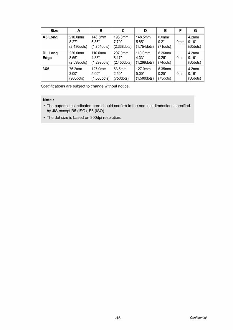
Specifications are subject to change without notice.
A5 Long 210.0mm8.27"(2,480dots)
148.5mm5.85"(1,754dots)
198.0mm7.79"(2,338dots)
148.5mm5.85"(1,754dots)
6.0mm0.2"(71dots)
0mm4.2mm0.16"(50dots)
DL Long Edge
220.0mm8.66"(2,598dots)
110.0mm4.33"(1,299dots)
207.0mm8.17"(2,450dots)
110.0mm4.33"(1,299dots)
6.26mm0.25"(74dots)
0mm4.2mm0.16"(50dots)
3X5 76.2mm3.00"(900dots)
127.0mm5.00"(1,500dots)
63.5mm2.50"(750dots)
127.0mm5.00"(1,500dots)
6.35mm0.25"(75dots)
0mm4.2mm0.16"(50dots)
Note :• The paper sizes indicated here should confirm to the nominal dimensions specified
by JIS except B5 (ISO), B6 (ISO).
• The dot size is based on 300dpi resolution.
Size A B C D E F G
1-16 Confidential
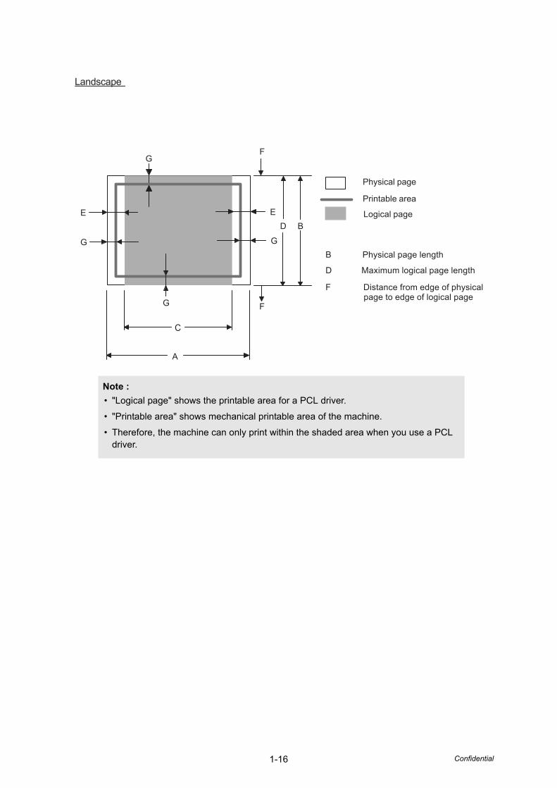
Note :• "Logical page" shows the printable area for a PCL driver.
• "Printable area" shows mechanical printable area of the machine.
• Therefore, the machine can only print within the shaded area when you use a PCL driver.
Landscape
A
B
C
DE
F
GF
G
E
G G
Physical page
Printable area
Logical page
B Physical page length
D Maximum logical page length
F Distance from edge of physical page to edge of logical page
1-17 Confidential
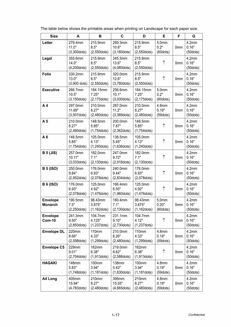
The table below shows the printable areas when printing on Landscape for each paper size.
Size A B C D E F GLetter 279.4mm
11.0"(3,300dots)
215.9mm8.5"(2,550dots)
269.3mm10.6"(3,180dots)
215.9mm8.5"(2,550dots)
5.0mm0.2"(60dots)
0mm4.2mm0.16"(50dots)
Legal 355.6mm14.0"(4,200dots)
215.9mm8.5"(2,550dots)
345.5mm13.6"(4,080dots)
215.9mm8.5"(2,550dots)
↑ 0mm4.2mm0.16"(50dots)
Folio 330.2mm13.0"(3,900 dots)
215.9mm8.5"(2,550dots)
320.0mm12.6"(3,780dots)
215.9mm8.5"(2,550dots)
↑ 0mm4.2mm0.16"(50dots)
Executive 266.7mm10.5"(3,150dots)
184.15mm7.25"(2,175dots)
256.6mm10.1"(3,030dots)
184.15mm7.25"(2,175dots)
5.0mm0.2"(60dots)
0mm4.2mm0.16"(50dots)
A 4 297.0mm11.69"(3,507dots)
210.0mm8.27"(2,480dots)
287.0mm11.2"(3,389dots)
210.0mm8.27"(2,480dots)
4.8mm0.19"(59dots)
0mm4.2mm0.16"(50dots)
A 5 210.0mm8.27"(2,480dots)
148.5mm5.85"(1,754dots)
200.0mm7.87"(2,362dots)
148.5mm5.85"(1,754dots)
↑ 0mm4.2mm0.16"(50dots)
A 6 148.5mm5.85"(1,754dots)
105.0mm4.13"(1,240dots)
138.5mm5.45"(1,636dots)
105.0mm4.13"(1,240dots)
↑ 0mm4.2mm0.16"(50dots)
B 5 (JIS) 257.0mm10.11"(3,033dots)
182.0mm7.1"(2,130dots)
247.0mm9.72"(2,916dots)
182.0mm7.1"(2,130dots)
↑ 0mm4.2mm0.16"(50dots)
B 5 (ISO) 250.0mm9.84"(2,952dots)
176.0mm6.93"(2,078dots)
240.0mm9.44"(2,834dots)
176.0mm6.93"(2,078dots)
↑ 0mm4.2mm0.16"(50dots)
B 6 (ISO) 176.0mm6.93"(2,078dots)
125.0mm4.92"(1,476dots)
166.4mm6.55"(1,960dots)
125.0mm4.92"(1,476dots)
↑ 0mm4.2mm0.16"(50dots)
Envelope Monarch
190.5mm7.5"(2,250dots)
98.43mm3.875"(1,162dots)
180.4mm7.1"(2,130dots)
98.43mm3.875"(1,162dots)
5.0mm0.20"(60dots)
0mm4.2mm0.16"(50dots)
Envelope Com-10
241.3mm9.50"(2,850dots)
104.7mm4.125"(1,237dots)
231.1mm9.10"(2,730dots)
104.7mm4.12"(1,237dots)
↑ 0mm4.2mm0.16"(50dots)
Envelope DL 220mm8.66"(2,598dots)
110mm4.33"(1,299dots)
210.0mm8.26"(2,480dots)
110mm4.33"(1,299dots)
4.8mm0.19"(59dots)
0mm4.2mm0.16"(50dots)
Envelope C5 229mm9.01"(2,704dots)
162mm6.38"(1,913dots)
219.0mm8.62"(2,586dots)
162mm6.38"(1,913dots)
↑ 0mm4.2mm0.16"(50dots)
HAGAKI 148mm5.83"(1,748dots)
100mm3.94"(1,181dots)
138mm5.43"(1,630dots)
100mm3.94"(1,181dots)
4.8mm0.19"(59dots)
0mm4.2mm0.16"(50dots)
A4 Long 405mm15.94"(4,783dots)
210mm8.27"(2,480dots)
395mm15.55"(4,665dots)
210mm8.27"(2,480dots)
4.8mm0.19"(59dots)
0mm4.2mm0.16"(50dots)
1-18 Confidential
Specifications are subject to change without notice.
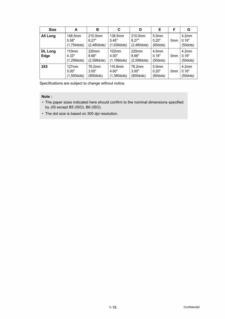
A5 Long 148.5mm5.58"(1,754dots)
210.0mm8.27"(2,480dots)
138.5mm5.45"(1,636dots)
210.0mm8.27"(2,480dots)
5.0mm0.20"(60dots)
0mm4.2mm0.16"(50dots)
DL Long Edge
110mm4.33"(1,299dots)
220mm8.66"(2,598dots)
102mm4.00"(1,199dots)
220mm8.66"(2,598dots)
4.0mm0.16"(50dots)
0mm4.2mm0.16"(50dots)
3X5 127mm5.00"(1,500dots)
76.2mm3.00"(900dots)
116.8mm4.60"(1,380dots)
76.2mm3.00"(900dots)
5.0mm0.20"(60dots)
0mm4.2mm0.16"(50dots)
Note :• The paper sizes indicated here should confirm to the nominal dimensions specified
by JIS except B5 (ISO), B6 (ISO).
• The dot size is based on 300 dpi resolution.
Size A B C D E F G
1-19 Confidential
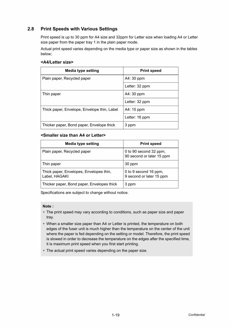
2.8 Print Speeds with Various SettingsPrint speed is up to 30 ppm for A4 size and 32ppm for Letter size when loading A4 or Letter size paper from the paper tray 1 in the plain paper mode.
Actual print speed varies depending on the media type or paper size as shown in the tables below;
<A4/Letter size>
<Smaller size than A4 or Letter>
Specifications are subject to change without notice.
Media type setting Print speed
Plain paper, Recycled paper A4: 30 ppm
Letter: 32 ppm
Thin paper A4: 30 ppm
Letter: 32 ppm
Thick paper, Envelope, Envelope thin, Label A4: 15 ppm
Letter: 16 ppm
Thicker paper, Bond paper, Envelope thick 3 ppm
Media type setting Print speed
Plain paper, Recycled paper 0 to 90 second 32 ppm,90 second or later 15 ppm
Thin paper 30 ppm
Thick paper, Envelopes, Envelopes thin, Label, HAGAKI
0 to 9 second 16 ppm,9 second or later 15 ppm
Thicker paper, Bond paper, Envelopes thick 3 ppm
Note :• The print speed may vary according to conditions, such as paper size and paper
tray.
• When a smaller size paper than A4 or Letter is printed, the temperature on both edges of the fuser unit is much higher than the temperature on the center of the unit where the paper is fed depending on the setting or model. Therefore, the print speed is slowed in order to decrease the temperature on the edges after the specified time, it is maximum print speed when you first start printing.
• The actual print speed varies depending on the paper size.
1-20 Confidential
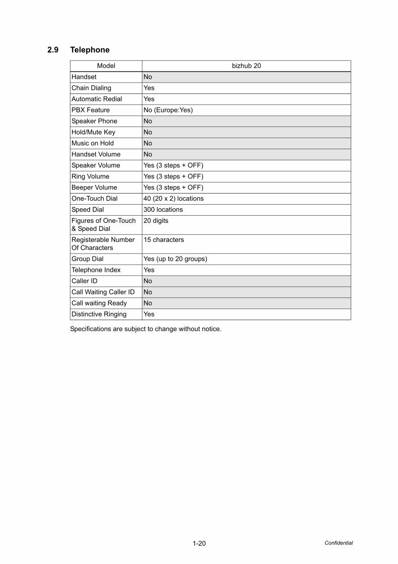
2.9 Telephone
Specifications are subject to change without notice.
Model bizhub 20Handset NoChain Dialing YesAutomatic Redial YesPBX Feature No (Europe:Yes)Speaker Phone NoHold/Mute Key NoMusic on Hold NoHandset Volume NoSpeaker Volume Yes (3 steps + OFF)Ring Volume Yes (3 steps + OFF)Beeper Volume Yes (3 steps + OFF)One-Touch Dial 40 (20 x 2) locationsSpeed Dial 300 locationsFigures of One-Touch & Speed Dial
20 digits
Registerable Number Of Characters
15 characters
Group Dial Yes (up to 20 groups)Telephone Index YesCaller ID NoCall Waiting Caller ID NoCall waiting Ready NoDistinctive Ringing Yes
1-21 Confidential
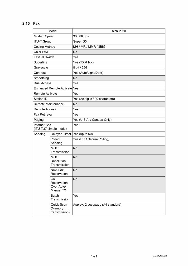
2.10 Fax
Model bizhub 20Modem Speed 33.600 bpsITU-T Group Super G3Coding Method MH / MR / MMR / JBIGColor FAX NoFax/Tel Switch YesSuperfine Yes (TX & RX)Grayscale 8 bit / 256Contrast Yes (Auto/Light/Dark)Smoothing NoDual Access YesEnhanced Remote Activate YesRemote Activate YesStation ID Yes (20 digits / 20 characters)Remote Maintenance NoRemote Access YesFax Retrieval YesPaging Yes (U.S.A. / Canada Only)Internet FAX (ITU T.37 simple mode)
Yes
Sending Delayed Timer Yes (up to 50)Polled Sending
Yes (EUR Secure Polling)
Multi Transmission
No
Multi Resolution Transmission
No
Next-Fax Reservation
No
Call Reservation Over Auto/Manual TX
No
Batch Transmission
Yes
Quick-Scan(Memory transmission)
Approx. 2 sec./page (A4 standard)
1-22 Confidential
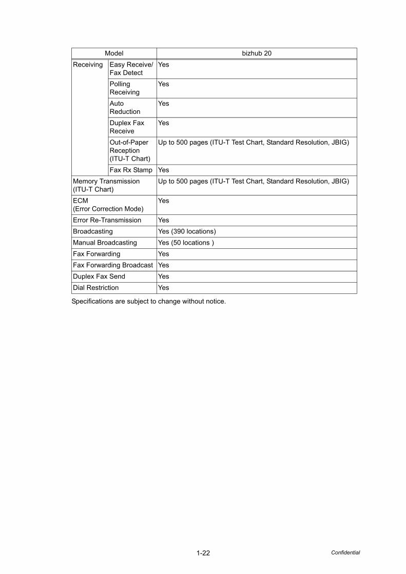
Specifications are subject to change without notice.
Receiving Easy Receive/Fax Detect
Yes
Polling Receiving
Yes
Auto Reduction
Yes
Duplex Fax Receive
Yes
Out-of-Paper Reception(ITU-T Chart)
Up to 500 pages (ITU-T Test Chart, Standard Resolution, JBIG)
Fax Rx Stamp YesMemory Transmission (ITU-T Chart)
Up to 500 pages (ITU-T Test Chart, Standard Resolution, JBIG)
ECM(Error Correction Mode)
Yes
Error Re-Transmission YesBroadcasting Yes (390 locations)Manual Broadcasting Yes (50 locations )Fax Forwarding YesFax Forwarding Broadcast YesDuplex Fax Send YesDial Restriction Yes
Model bizhub 20
1-23 Confidential
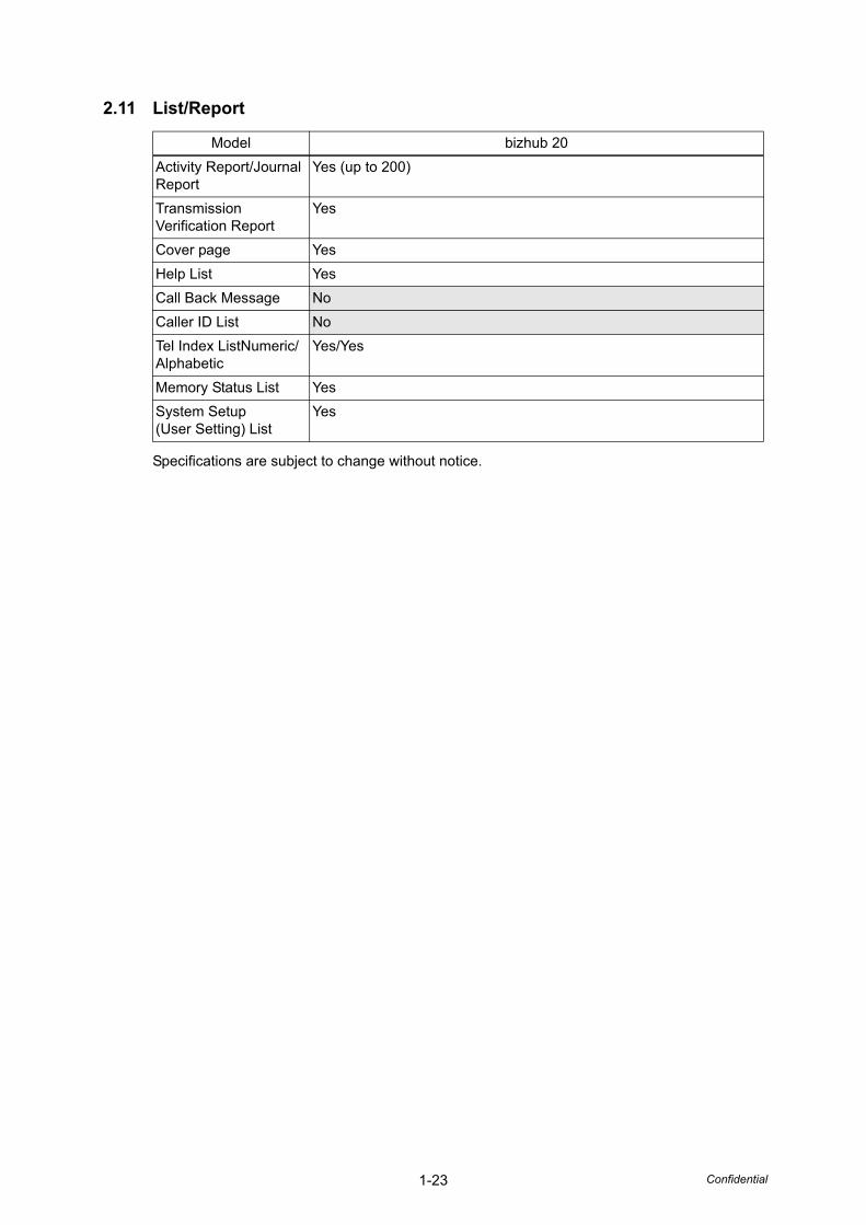
2.11 List/Report
Specifications are subject to change without notice.
Model bizhub 20Activity Report/Journal Report
Yes (up to 200)
Transmission Verification Report
Yes
Cover page YesHelp List YesCall Back Message NoCaller ID List NoTel Index ListNumeric/ Alphabetic
Yes/Yes
Memory Status List YesSystem Setup(User Setting) List
Yes
1-24 Confidential
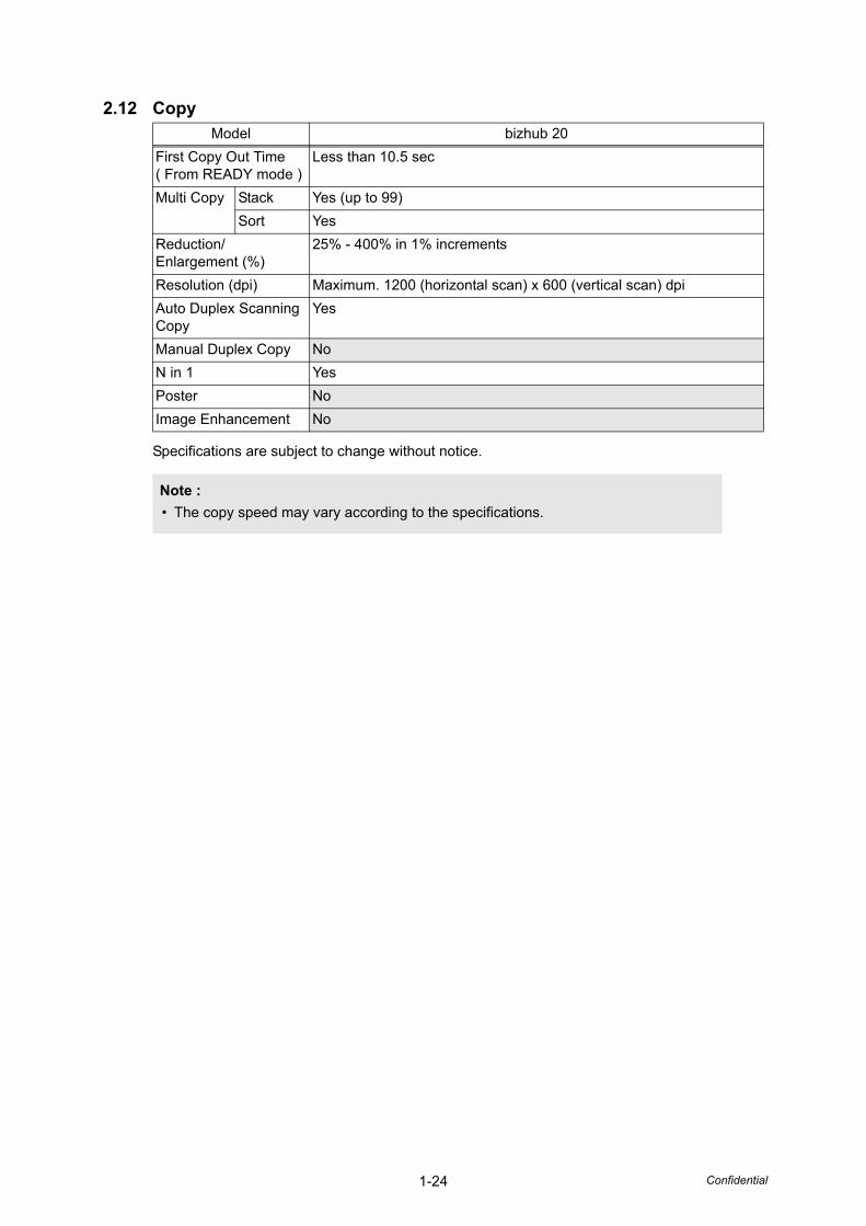
2.12 Copy
Specifications are subject to change without notice.
Model bizhub 20First Copy Out Time ( From READY mode )
Less than 10.5 sec
Multi Copy Stack Yes (up to 99)Sort Yes
Reduction/Enlargement (%)
25% - 400% in 1% increments
Resolution (dpi) Maximum. 1200 (horizontal scan) x 600 (vertical scan) dpiAuto Duplex Scanning Copy
Yes
Manual Duplex Copy NoN in 1 YesPoster NoImage Enhancement No
Note :• The copy speed may vary according to the specifications.
1-25 Confidential
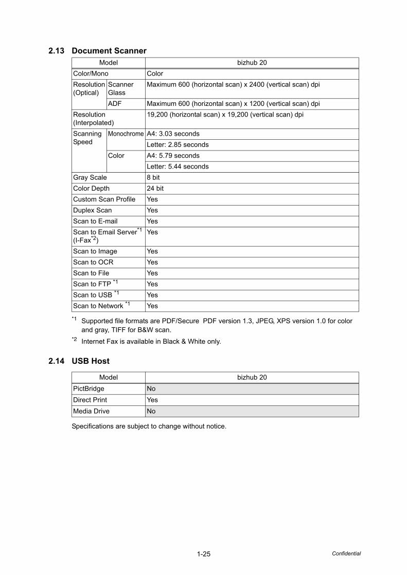
2.13 Document Scanner
*1 Supported file formats are PDF/Secure PDF version 1.3, JPEG, XPS version 1.0 for color and gray, TIFF for B&W scan.
*2 Internet Fax is available in Black & White only.
2.14 USB Host
Specifications are subject to change without notice.
Model bizhub 20Color/Mono ColorResolution(Optical)
Scanner Glass
Maximum 600 (horizontal scan) x 2400 (vertical scan) dpi
ADF Maximum 600 (horizontal scan) x 1200 (vertical scan) dpiResolution (Interpolated)
19,200 (horizontal scan) x 19,200 (vertical scan) dpi
Scanning Speed
Monochrome A4: 3.03 secondsLetter: 2.85 seconds
Color A4: 5.79 secondsLetter: 5.44 seconds
Gray Scale 8 bitColor Depth 24 bitCustom Scan Profile YesDuplex Scan YesScan to E-mail YesScan to Email Server*1 (I-Fax*2)
Yes
Scan to Image YesScan to OCR YesScan to File YesScan to FTP *1 YesScan to USB *1 YesScan to Network *1 Yes
Model bizhub 20PictBridge NoDirect Print YesMedia Drive No

Confidential
CHAPTER 2THEORY OF OPERATION
Confidential
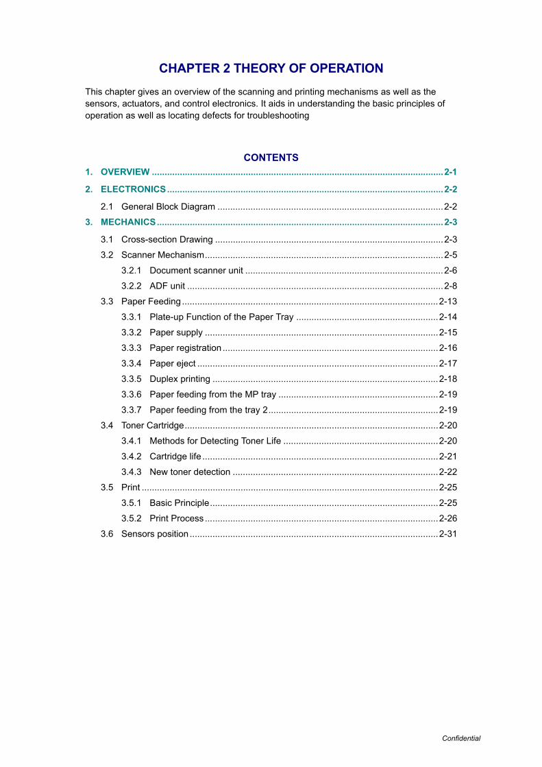
CHAPTER 2 THEORY OF OPERATION
This chapter gives an overview of the scanning and printing mechanisms as well as the sensors, actuators, and control electronics. It aids in understanding the basic principles of operation as well as locating defects for troubleshooting
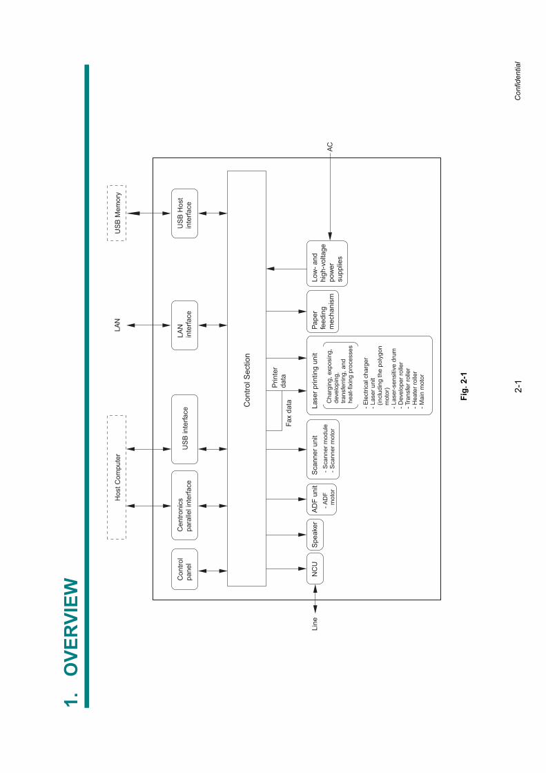
CONTENTS1. OVERVIEW ...................................................................................................................2-1
2. ELECTRONICS.............................................................................................................2-2
2.1 General Block Diagram .........................................................................................2-2
3. MECHANICS.................................................................................................................2-3
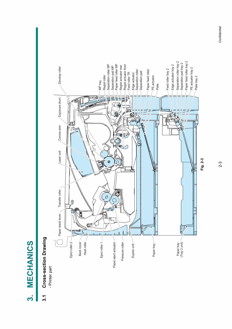
3.1 Cross-section Drawing ..........................................................................................2-3
3.2 Scanner Mechanism..............................................................................................2-5
3.2.1 Document scanner unit ..............................................................................2-6
3.2.2 ADF unit .....................................................................................................2-8
3.3 Paper Feeding .....................................................................................................2-13
3.3.1 Plate-up Function of the Paper Tray ........................................................2-14
3.3.2 Paper supply ............................................................................................2-15
3.3.3 Paper registration .....................................................................................2-16
3.3.4 Paper eject ...............................................................................................2-17
3.3.5 Duplex printing .........................................................................................2-18
3.3.6 Paper feeding from the MP tray ...............................................................2-19
3.3.7 Paper feeding from the tray 2...................................................................2-19
3.4 Toner Cartridge....................................................................................................2-20
3.4.1 Methods for Detecting Toner Life .............................................................2-20
3.4.2 Cartridge life .............................................................................................2-21
3.4.3 New toner detection .................................................................................2-22
3.5 Print .....................................................................................................................2-25
3.5.1 Basic Principle..........................................................................................2-25
3.5.2 Print Process ............................................................................................2-26
3.6 Sensors position ..................................................................................................2-31
2-1
Confidential
1.O
VER
VIEW
Fig.
2-1
Con
trol S
ectio
n
Cen
troni
cspa
ralle
l int
erfa
ceU
SB
inte
rface
Hos
t Com
pute
rU
SB
Mem
ory
Con
trol
pane
lLA
Nin
terfa
ceU
SB
Hos
tin
terfa
ce
Prin
ter
data
Fax
data
Low
- and
high
-vol
tage
pow
ersu
pplie
sAC
LAN
Pape
rfe
edin
gm
echa
nism
Lase
r prin
ting
unit
Cha
rgin
g, e
xpos
ing,
deve
lopi
ng,
trans
ferr
ing,
and
heat
-fixi
ng p
roce
sses
- Ele
ctric
al c
harg
er- L
aser
uni
t (
incl
udin
g th
e po
lygo
n m
otor
)- L
aser
-sen
sitiv
e dr
um- D
evel
oper
rolle
r- T
rans
fer r
olle
r- H
eate
r rol
ler
- Mai
n m
otor
Sca
nner
uni
tA
DF
unit
NC
ULi
neS
peak
er- S
cann
er m
odul
e- S
cann
er m
otor
- AD
F m
otor
2-2 Confidential
2. ELECTRONICS
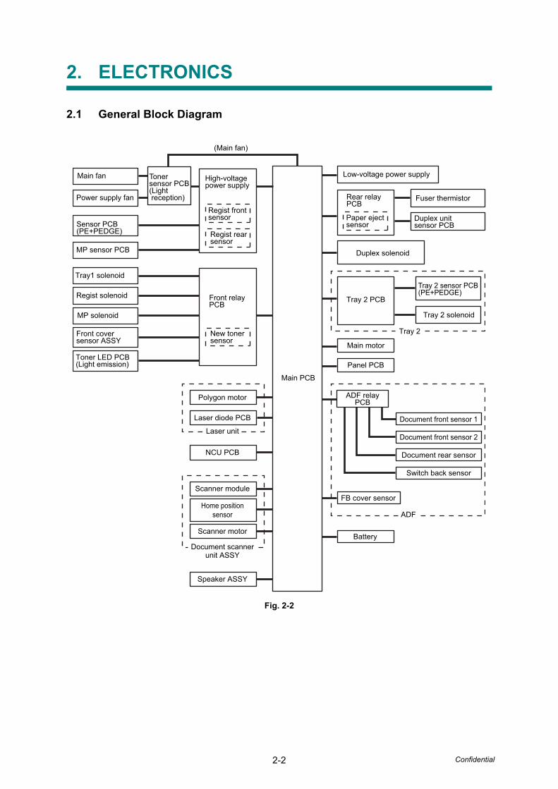
2.1 General Block Diagram
Fig. 2-2
High-voltagepower supply
Low-voltage power supply
Fuser thermistor
Main PCB
Regist frontsensor
Main fan
Tray 2 sensor PCB(PE+PEDGE)
Regist rearsensor
Tonersensor PCB(Light reception)
(Main fan)
Toner LED PCB(Light emission)
Power supply fan
Front cover sensor ASSY
MP sensor PCB
Tray1 solenoid
Regist solenoid
Main motor
Panel PCB
Duplex solenoid
Duplex unit sensor PCB
MP solenoid Tray 2 solenoid
Front relayPCB
New tonersensor
Rear relayPCB
Paper ejectsensor
Tray 2 PCB
Tray 2
Polygon motor
Laser diode PCB
Sensor PCB(PE+PEDGE)
Document front sensor 1
Document front sensor 2
Document rear sensor
Switch back sensor
Document scannerunit ASSY
ADF
Laser unit
ADF relayPCB
Battery
NCU PCB
Speaker ASSY
Scanner motor
Scanner module
Home positionsensor
FB cover sensor
2-3
Confidential
3.M
ECH
AN
ICS
3.1
Cro
ss-s
ectio
n D
raw
ing
- Prin
ter p
art
Fig.
2-3
MP
Dup
lex
unit
Expo
sure
dru
mC
oron
a w
ireLa
ser u
nit
Ejec
t rol
ler 2
Hea
t rol
ler
Pape
r eje
ct a
ctua
tor
Pres
sure
rolle
r
Back
cov
er
Tran
sfer
rolle
rPa
per s
tack
leve
r
Pape
r tra
y
Pape
r tra
y (T
ray
2 un
it)
Pape
r fee
d ro
ller M
P
Sepa
ratio
n ro
ller M
P
Pape
r fee
d ro
ller
Sepa
ratio
n ro
ller
Reg
ist a
ctua
tor f
ront
Reg
ist a
ctua
tor r
ear
PE a
ctua
tor
Feed
rolle
r TR
Sepa
ratio
n ro
ller t
ray
2
Feed
rolle
r tra
y 2
Pape
r fee
d ro
ller t
ray
2
Edge
act
uato
r
Plat
e
Sepa
ratio
n pa
d
Sepa
ratio
n pa
d M
P
MP
tray
Reg
ist r
olle
r
Dev
elop
rolle
r
Plat
e tra
y 2
Sepa
ratio
n pa
d tra
y 2
PE a
ctua
tor t
ray
2
Edge
act
uato
r tra
y 2
Ejec
t rol
ler 1
2-4
Confidential
- AD
F pa
rt
Fig.
2-4
Gui
de S
haft
CC
D d
rive
belt
Pul
ley
AS
SY
Doc
umen
t fro
nt s
enso
r 1
Doc
umen
t fro
nt s
enso
r act
uato
r 2
Doc
umen
t fro
nt s
enso
r act
uato
r 1
Pic
k-up
rolle
r
Eje
ct ro
ller
Sep
arat
ion
rolle
r
Doc
umen
t fro
nt s
enso
r 2
Pap
er fe
ed
rolle
r 1
Sw
itch
back
rolle
r AS
SY
Flap
C
Flap
A
Flap
B
Sw
itch
back
se
nsor
act
uato
r
Pap
er fe
ed ro
ller 4
Sw
itch
back
se
nsor
Pap
er fe
ed ro
ller 2
Doc
umen
t rea
r sen
sor
Doc
umen
t rea
r se
nsor
act
uato
r
Pap
er fe
ed
rolle
r 3
Hom
e po
sitio
n se
nsor
CC
D m
odul
e
2-5 Confidential
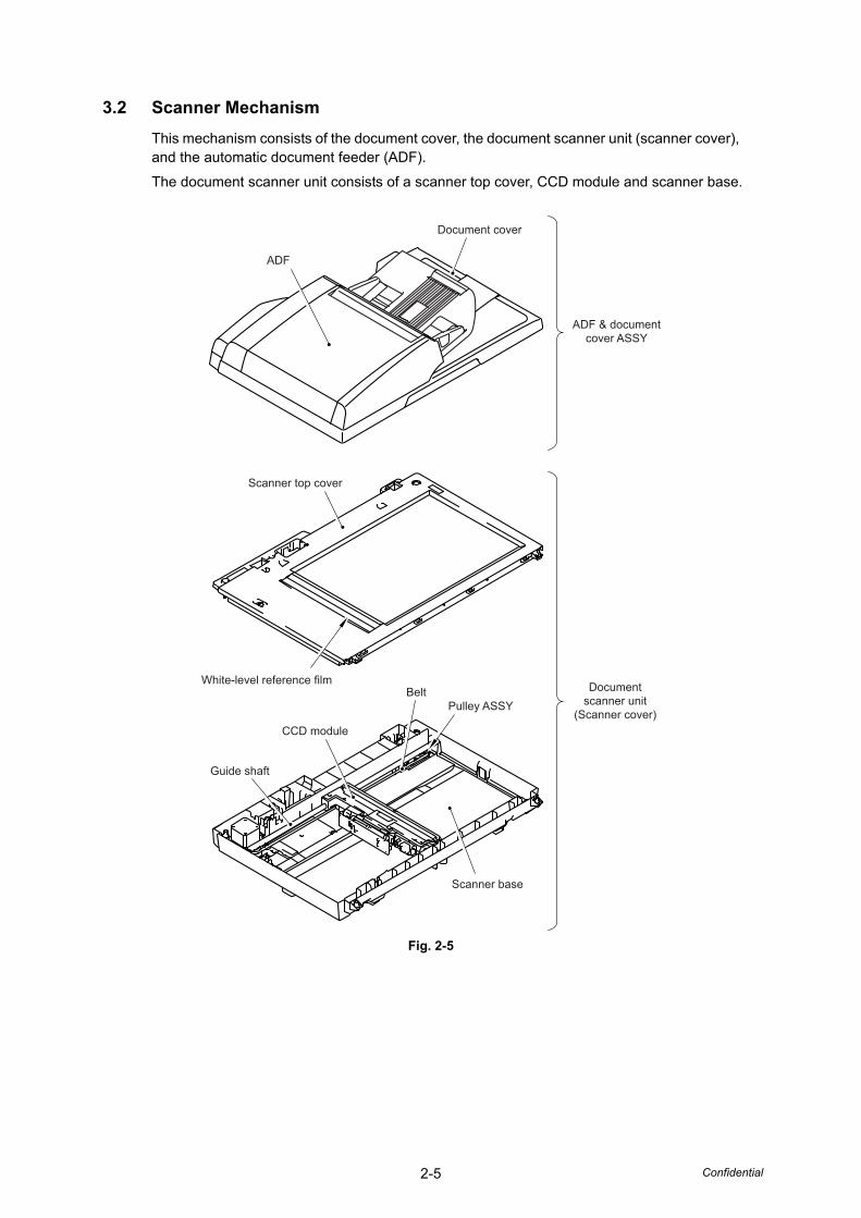
3.2 Scanner MechanismThis mechanism consists of the document cover, the document scanner unit (scanner cover), and the automatic document feeder (ADF).
The document scanner unit consists of a scanner top cover, CCD module and scanner base.
Fig. 2-5
ADF
Scanner top cover
White-level reference film
CCD module
Guide shaft
Scanner base
Pulley ASSYBelt
Document cover
ADF & documentcover ASSY
Documentscanner unit
(Scanner cover)
2-6 Confidential
3.2.1 Document scanner unitThe document scanner unit is equipment which scans the paper using the scanner module. This machine prints the scanning data (copy) or sends data as FAX (FAX transmission).
There are two kinds of scanning method of the document scanner unit. One is operation to scan with the document scanner unit, the paper is placed on the document glass, the scanner module moves under the document glass, and it scans the paper, and the other one is operation to scan in cooperation with the ADF unit, scan the paper which has been sent over the immovable scanner module.
1. CCD unitThe CCD unit includes the charge coupled device (CCD) sensor (Resolution of horizontal scanning: Max 600dpi, color scanning). The fluorescent lamp lights the document, and the reflection from the scanned image data is transferred to the lens by the mirror. The lens reduces the scanned data so that the image is generated on the CCD.
2. Driving of the scanner moduleThe scanner module is supported by the guide shaft and assembled on the drive belt. When the scanner motor is rotated clockwise, the scanner module on the drive belt scans the document while sliding to the right hand side. In this case, the CCD unit has the capacity to scan at 2,400dpi resolution of sub scanning.
3. Scanner module home position detection (FB home position detection)The scanner module is configured at the FB home position to determine the scanning position of the sub scanning direction. Based on the home position, the position performing the white level compensation or the scan lock other than the scanning position is configured.
The FB home position is detected when the scanner module intercepts the home position sensor in the left side of the inside of the document scanner unit.
4. White level compensationWhenever the variation of the scanner module by scanner module, the correction of the time degradation and the value of the while color scans, in order to make them not different.
The white level compensation keeps a fixed value of the white color by scanning the white-level reference film inside the document scanner unit with the scanner module.
5. Function of scanner lock leverThe scanner lock lever works to fix the CCD unit to protect the machine from the damage by moving CCD unit during transportation.
2-7 Confidential
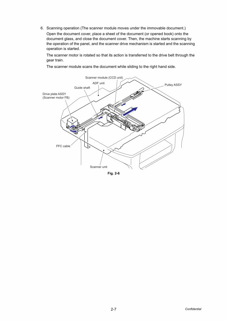
6. Scanning operation (The scanner module moves under the immovable document.)Open the document cover, place a sheet of the document (or opened book) onto the document glass, and close the document cover. Then, the machine starts scanning by the operation of the panel, and the scanner drive mechanism is started and the scanning operation is started.
The scanner motor is rotated so that its action is transferred to the drive belt through the gear train.
The scanner module scans the document while sliding to the right hand side.
Fig. 2-6
Pulley ASSY
Scanner module (CCD unit)
ADF unitGuide shaft
Drive plate ASSY(Scanner motor FB)
FFC cable
Scanner unit
2-8 Confidential
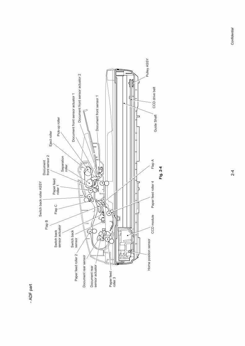
3.2.2 ADF unitThe ADF unit is equipment which sends one document or the document for every plurality to the ADF scanning part of the document scanner unit, and performs continuation scanning. As for the ADF of this machine, the duplex scanning is also possible.Performance of the ADF
- The number of maximum capacity: Up to 50 sheets.
- Maximum resolution: Up to 600dpi
- Maximum scanning speed:32 pages/minute (Letter size) (Simplex scanning)14 pages/minute (Letter size) (7 sheets/minute) (Duplex scanning)
- Maximum input media size (Simplex): Width 215.9mm, Length 355.6mm
- Minimum input media size (Simplex): Width 148.0mm, Length 148.0mm
- Maximum input media size (Duplex): Width 215.9mm, Length 297.0mm
- Minimum input media size (Duplex): Width 148.0mm, Length 148.0mm
1. Function of each roller- Pick-up roller
Send the document from on the ADF into the ADF.- Separation roller
Separate the sent document one by one.- Paper feed roller 1, 2, 3, 4
Send the document.- Switch back roller ASSY
When the duplex scanning, this motor is rotated by contraries, draws the sent out document to the inside of ADF again.
- Eject rollerEject the document.
2. Function of each sensor- Document front sensor 1
Detects whether the document is set in the ADF.- Document front sensor 2
Detects whether the document is sent by the separation roller.- Document rear sensor
Detect the timing of the scanning start of the document.- Switch back sensor
When the duplex scanning, detect the timing of the reversing of the switch back roller by the document passed.
- Document cover open sensorDetects whether the document cover is opened or not. Even if the document is set into the ADF, the machine starts scanning the document glass ignoring the ADF.
2-9 Confidential
3. Function of each motor/solenoid- ADF motor
Driving source of overall ADF.- Paper feed solenoid
The paper feed solenoid disable pick-up roller and separation roller while the machine is taking action scanning to prevent the next document from being drawn into the ADF.
- Switch back solenoidSwitches the direction of rotation of the switch back roller ASSY.
- Document eject sensorWhen the duplex scanning, detects whether the document is ejected.
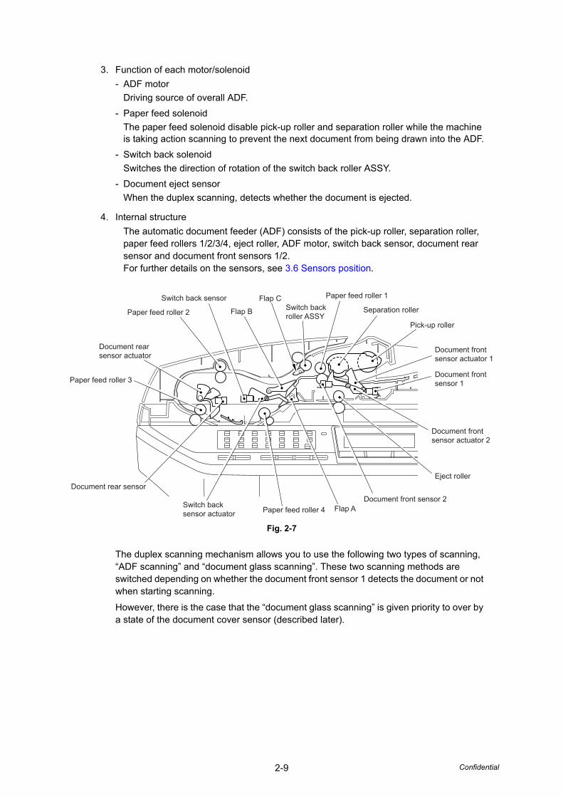
4. Internal structureThe automatic document feeder (ADF) consists of the pick-up roller, separation roller, paper feed rollers 1/2/3/4, eject roller, ADF motor, switch back sensor, document rear sensor and document front sensors 1/2.For further details on the sensors, see 3.6 Sensors position.
Fig. 2-7
The duplex scanning mechanism allows you to use the following two types of scanning, “ADF scanning” and “document glass scanning”. These two scanning methods are switched depending on whether the document front sensor 1 detects the document or not when starting scanning.
However, there is the case that the “document glass scanning” is given priority to over by a state of the document cover sensor (described later).
Switch back sensor
Paper feed roller 2
Document rear sensor actuator
Paper feed roller 3
Document rear sensor
Switch back sensor actuator Paper feed roller 4 Flap A
Document front sensor 2
Eject roller
Document frontsensor actuator 2
Document frontsensor 1
Document frontsensor actuator 1
Pick-up roller
Separation roller
Paper feed roller 1Switch backroller ASSY
Flap C
Flap B
2-10 Confidential
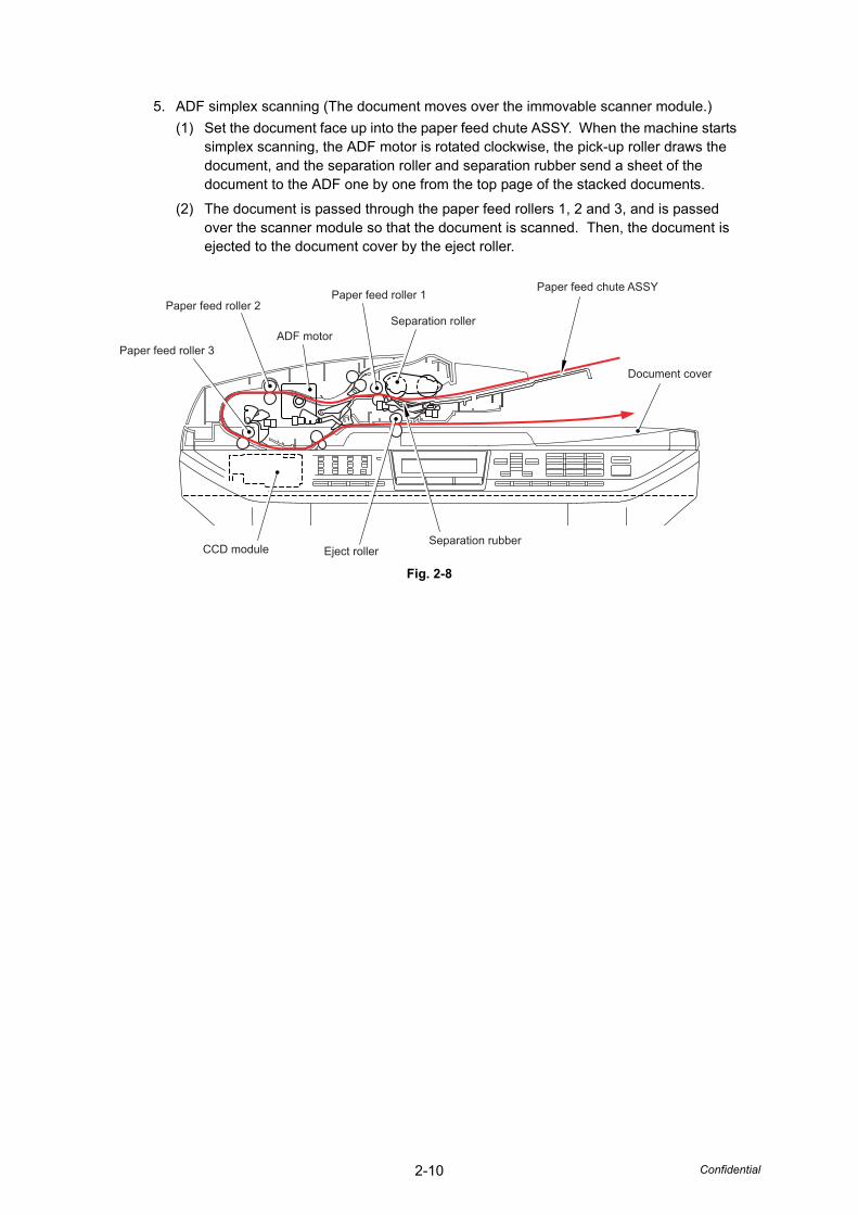
5. ADF simplex scanning (The document moves over the immovable scanner module.)(1) Set the document face up into the paper feed chute ASSY. When the machine starts
simplex scanning, the ADF motor is rotated clockwise, the pick-up roller draws the document, and the separation roller and separation rubber send a sheet of the document to the ADF one by one from the top page of the stacked documents.
(2) The document is passed through the paper feed rollers 1, 2 and 3, and is passed over the scanner module so that the document is scanned. Then, the document is ejected to the document cover by the eject roller.
Fig. 2-8
Document cover
Paper feed chute ASSY
Separation roller
Paper feed roller 1
ADF motor
Paper feed roller 2
Paper feed roller 3
CCD module Eject rollerSeparation rubber
2-11 Confidential
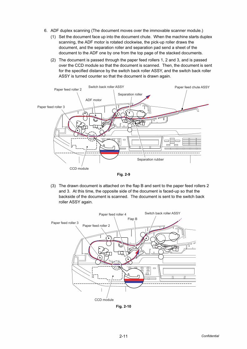
6. ADF duplex scanning (The document moves over the immovable scanner module.)(1) Set the document face up into the document chute. When the machine starts duplex
scanning, the ADF motor is rotated clockwise, the pick-up roller draws the document, and the separation roller and separation pad send a sheet of the document to the ADF one by one from the top page of the stacked documents.
(2) The document is passed through the paper feed rollers 1, 2 and 3, and is passed over the CCD module so that the document is scanned. Then, the document is sent for the specified distance by the switch back roller ASSY, and the switch back roller ASSY is turned counter so that the document is drawn again.
Fig. 2-9
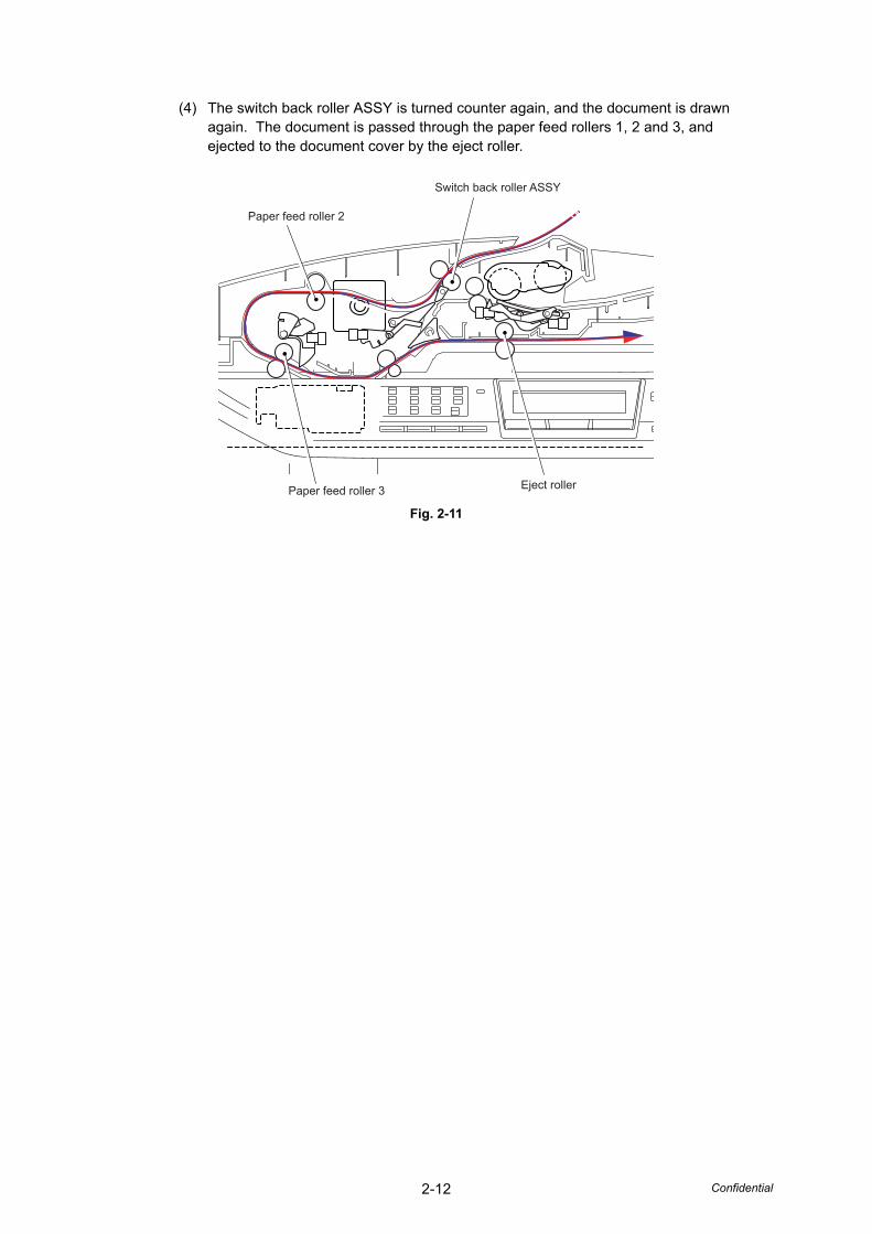
(3) The drawn document is attached on the flap B and sent to the paper feed rollers 2 and 3. At this time, the opposite side of the document is faced-up so that the backside of the document is scanned. The document is sent to the switch back roller ASSY again.
Fig. 2-10
Paper feed chute ASSY
Separation rubber
CCD module
Paper feed roller 3
Paper feed roller 2Switch back roller ASSY
ADF motor
Separation roller
Switch back roller ASSY
Flap BPaper feed roller 4
Paper feed roller 2Paper feed roller 3
CCD module
2-12 Confidential
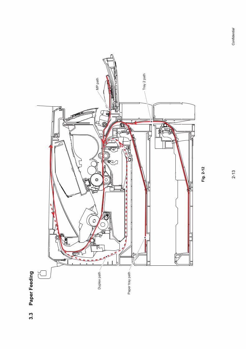
(4) The switch back roller ASSY is turned counter again, and the document is drawn again. The document is passed through the paper feed rollers 1, 2 and 3, and ejected to the document cover by the eject roller.
Fig. 2-11
Switch back roller ASSY
Paper feed roller 2
Paper feed roller 3 Eject roller
2-13
Confidential
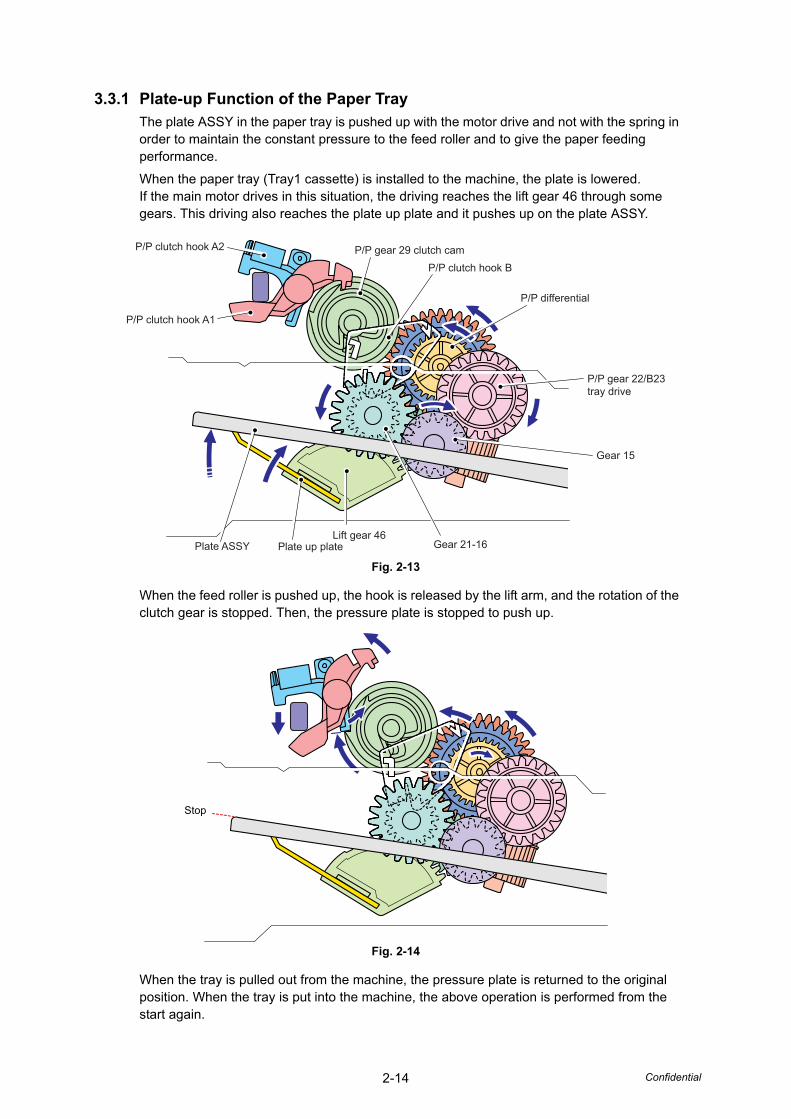
3.3
Pape
r Fee
ding
Fig.
2-1
2
Tray
2 p
ath
Dup
lex
path
MP
path
Pap
er tr
ay p
ath
2-14 Confidential
3.3.1 Plate-up Function of the Paper TrayThe plate ASSY in the paper tray is pushed up with the motor drive and not with the spring in order to maintain the constant pressure to the feed roller and to give the paper feeding performance.
When the paper tray (Tray1 cassette) is installed to the machine, the plate is lowered. If the main motor drives in this situation, the driving reaches the lift gear 46 through some gears. This driving also reaches the plate up plate and it pushes up on the plate ASSY.
Fig. 2-13
When the feed roller is pushed up, the hook is released by the lift arm, and the rotation of the clutch gear is stopped. Then, the pressure plate is stopped to push up.
Fig. 2-14
When the tray is pulled out from the machine, the pressure plate is returned to the original position. When the tray is put into the machine, the above operation is performed from the start again.
Lift gear 46Gear 21-16
Gear 15
P/P gear 22/B23tray drive
P/P clutch hook B
Plate up platePlate ASSY
P/P differential
P/P gear 29 clutch camP/P clutch hook A2
P/P clutch hook A1
Stop
2-15 Confidential
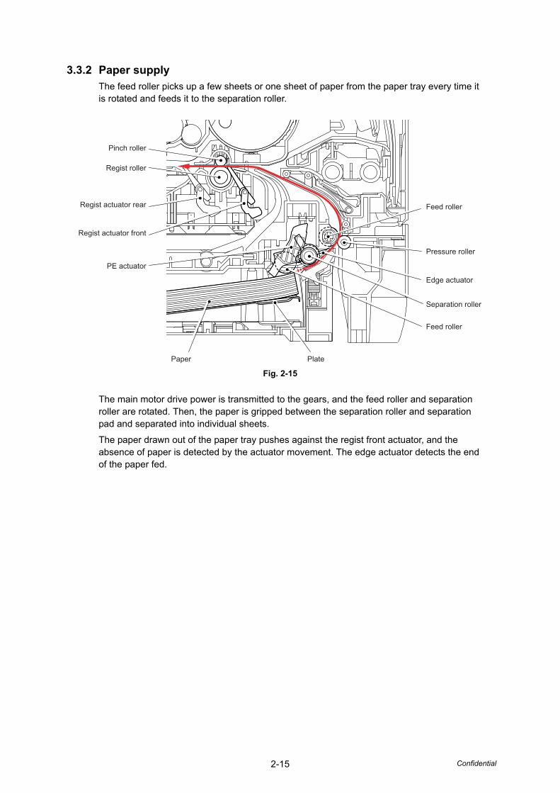
3.3.2 Paper supplyThe feed roller picks up a few sheets or one sheet of paper from the paper tray every time it is rotated and feeds it to the separation roller.
Fig. 2-15
The main motor drive power is transmitted to the gears, and the feed roller and separation roller are rotated. Then, the paper is gripped between the separation roller and separation pad and separated into individual sheets.
The paper drawn out of the paper tray pushes against the regist front actuator, and the absence of paper is detected by the actuator movement. The edge actuator detects the end of the paper fed.
Feed roller
Separation roller
Feed roller
Pressure roller
Edge actuator
PlatePaper
PE actuator
Regist roller
Regist actuator front
Regist actuator rear
Pinch roller
2-16 Confidential
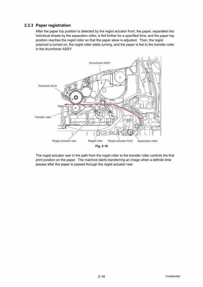
3.3.3 Paper registrationAfter the paper top position is detected by the regist actuator front, the paper, separated into individual sheets by the separation roller, is fed further for a specified time, and the paper top position reaches the regist roller so that the paper skew is adjusted. Then, the regist solenoid is turned on, the regist roller starts turning, and the paper is fed to the transfer roller in the drum/toner ASSY.
Fig. 2-16
The regist actuator rear in the path from the regist roller to the transfer roller controls the first print position on the paper. The machine starts transferring an image when a definite time passes after the paper is passed through the regist actuator rear.
Regist actuator front Separation rollerRegist actuator rear Regist roller
Drum/toner ASSY
Transfer roller
Exposure drum
2-17 Confidential
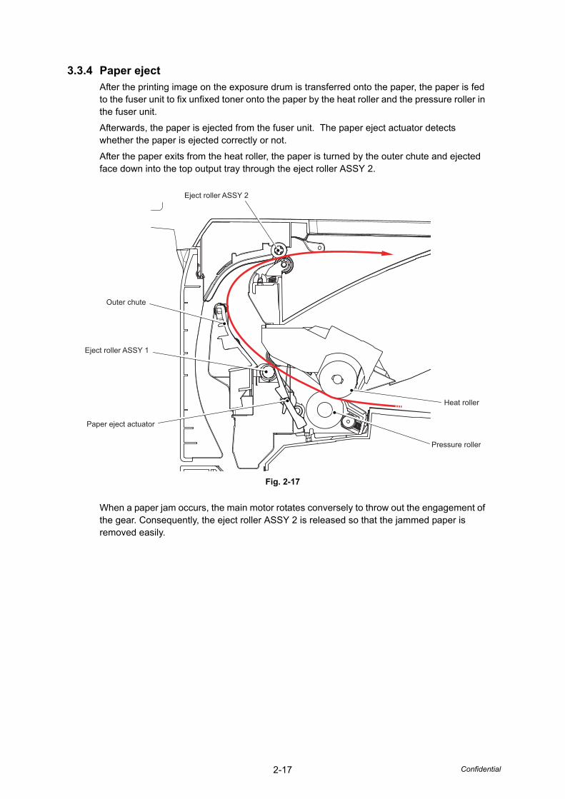
3.3.4 Paper ejectAfter the printing image on the exposure drum is transferred onto the paper, the paper is fed to the fuser unit to fix unfixed toner onto the paper by the heat roller and the pressure roller in the fuser unit.
Afterwards, the paper is ejected from the fuser unit. The paper eject actuator detects whether the paper is ejected correctly or not.
After the paper exits from the heat roller, the paper is turned by the outer chute and ejected face down into the top output tray through the eject roller ASSY 2.
Fig. 2-17
When a paper jam occurs, the main motor rotates conversely to throw out the engagement of the gear. Consequently, the eject roller ASSY 2 is released so that the jammed paper is removed easily.
Eject roller ASSY 2
Pressure roller
Heat roller
Outer chute
Eject roller ASSY 1
Paper eject actuator
2-18 Confidential
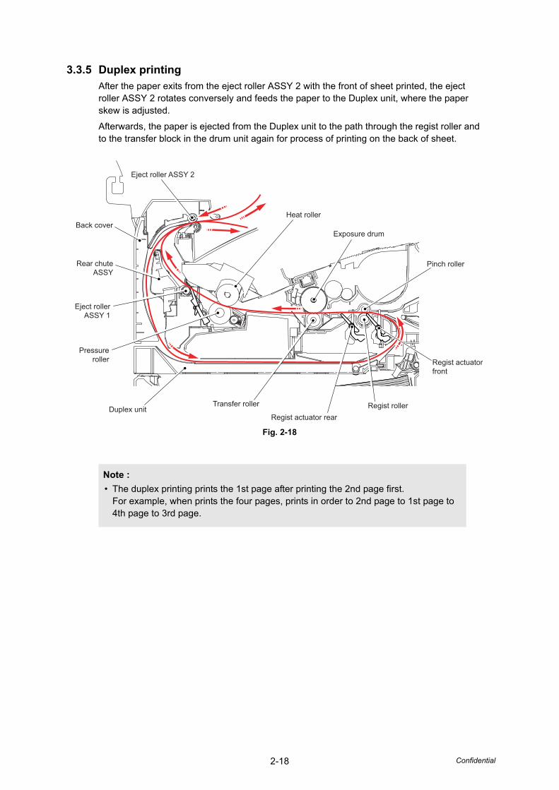
3.3.5 Duplex printingAfter the paper exits from the eject roller ASSY 2 with the front of sheet printed, the eject roller ASSY 2 rotates conversely and feeds the paper to the Duplex unit, where the paper skew is adjusted.
Afterwards, the paper is ejected from the Duplex unit to the path through the regist roller and to the transfer block in the drum unit again for process of printing on the back of sheet.
Fig. 2-18
Note :• The duplex printing prints the 1st page after printing the 2nd page first.
For example, when prints the four pages, prints in order to 2nd page to 1st page to 4th page to 3rd page.
Regist roller
Eject roller ASSY 2
Pressureroller
Eject rollerASSY 1
Heat roller
Exposure drum
Pinch roller
Regist actuatorfront
Duplex unitRegist actuator rear
Transfer roller
Rear chuteASSY
Back cover
2-19 Confidential
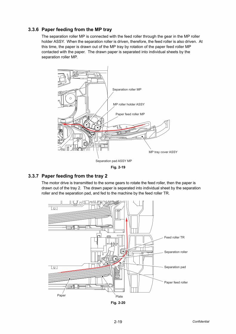
3.3.6 Paper feeding from the MP trayThe separation roller MP is connected with the feed roller through the gear in the MP roller holder ASSY. When the separation roller is driven, therefore, the feed roller is also driven. At this time, the paper is drawn out of the MP tray by rotation of the paper feed roller MP contacted with the paper. The drawn paper is separated into individual sheets by the separation roller MP.
Fig. 2-19
3.3.7 Paper feeding from the tray 2The motor drive is transmitted to the some gears to rotate the feed roller, then the paper is drawn out of the tray 2. The drawn paper is separated into individual sheet by the separation roller and the separation pad, and fed to the machine by the feed roller TR.
Fig. 2-20
Separation roller MP
Paper feed roller MP
MP roller holder ASSY
MP tray cover ASSY
Separation pad ASSY MP
Feed roller TR
Separation roller
Separation pad
Paper feed roller
PlatePaper
2-20 Confidential
3.4 Toner Cartridge
3.4.1 Methods for Detecting Toner LifeWhen the machine detects the toner life end, "Replace Toner" is displayed. The toner life is displayed through the following two ways. First, such indication is displayed when detection is performed by the toner sensor; second, it is displayed at the time when a cumulative rotation of the develop roller reaches its upper limit.
(1) Detection by the toner sensor
The low amount of toner remaining can be detected by checking the imperviousness to light of the toner in the cartridge by means of the transmissive photosensor.
(2) Detection by means of rotation rates of the develop roller reached its upper limit
The machine counts the accumulated number of the rotations for the develop roller.
2-21 Confidential
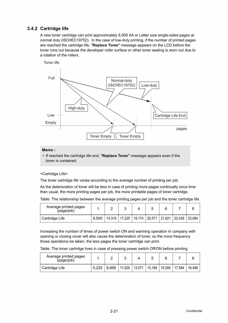
3.4.2 Cartridge lifeA new toner cartridge can print approximately 8,000 A4 or Letter size single-sided pages at normal duty (ISO/IEC19752). In the case of low-duty printing, if the number of printed pages are reached the cartridge life, "Replace Toner" message appears on the LCD before the toner runs out because the developer roller surface or other toner sealing is worn out due to a rotation of the rollers.
<Cartridge Life>
The toner cartridge life varies according to the average number of printing per job.
As the deterioration of toner will be less in case of printing more pages continually once time than usual, the more printing pages per job, the more printable pages of toner cartridge.
Increasing the number of times of power switch ON and warming operation in company with opening or closing cover will also cause the deterioration of toner, so the more frequency those operations be taken, the less pages the toner cartridge can print.
Memo :• If reached the cartridge life end, "Replace Toner" message appears even if the
toner is contained.
Table: The relationship between the average printing pages per job and the toner cartridge life
Average printed pages(page/job) 1 2 3 4 5 6 7 8
Cartridge Life 9,500 14,315 17,225 19,174 20,571 21,621 22,439 23,094
Table: The toner cartridge lives in case of pressing power switch Off/ON before printing.
Average printed pages(page/job) 1 2 3 4 5 6 7 8
Cartridge Life 5,225 8,856 11,526 13,571 15,189 16,500 17,584 18,496
Toner life
Full
Low
Emptypages
Cartridge Life End
Toner EmptyToner Empty
Low-duty
High-duty
Normal-duty(ISO/IEC19752)
2-22 Confidential
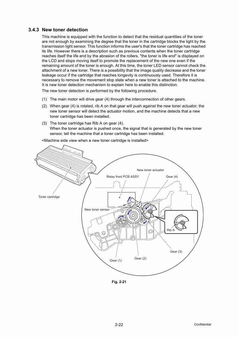
3.4.3 New toner detectionThis machine is equipped with the function to detect that the residual quantities of the toner are not enough by examining the degree that the toner in the cartridge blocks the light by the transmission light sensor. This function informs the user's that the toner cartridge has reached its life. However there is a description such as previous contents when the toner cartridge reaches itself the life end by the abrasion of the rollers, "the toner is life end" is displayed on the LCD and stops moving itself to promote the replacement of the new one even if the remaining amount of the toner is enough. At this time, the toner LED sensor cannot check the attachment of a new toner. There is a possibility that the image quality decrease and the toner leakage occur if the cartridge that reaches longevity is continuously used. Therefore it is necessary to remove the movement stop state when a new toner is attached to the machine. It is new toner detection mechanism to explain here to enable this distinction.The new toner detection is performed by the following procedure.
(1) The main motor will drive gear (4) through the interconnection of other gears.
(2) When gear (4) is rotated, rib A on that gear will push against the new toner actuator; the new toner sensor will detect the actuator motion, and the machine detects that a new toner cartridge has been installed.
(3) The toner cartridge has Rib A on gear (4). When the toner actuator is pushed once, the signal that is generated by the new toner sensor, tell the machine that a toner cartridge has been installed.
<Machine side view when a new toner cartridge is installed>
Fig. 2-21
Gear (4)
Gear (3)
Rib A
Gear (1)Gear (2)
New toner actuator
New toner sensor
Toner cartridge
Relay front PCB ASSY

2-23 Confidential
When the new toner detection machanism detects that the toner cartridge is replaced with a new one, the developing bias voltage is initialized at the same time.
The toner used for the machine has a property that print density is light first and gradually darker in the course of usage. The developing bias controls the toner property so that the print density is constant from first to last.
To obtain a print result of a constant density all the time, the machine counts the number of print pages immediately after the toner cartridge is replaced and changes the bias voltage according to the accumulated number of prints with the toner cartridge.
The bias voltage is changed with the steps described below:
(1) When the new toner sensor detects that the toner cartridge is replaced with a new (full) one, the developing bias is set to 400V (initialized).
(2) After that, the bias voltage is stepped down according to the number of prints. Ultimately, the bias voltage is approximately 300V.
<When a new toner cartridge is inserted after "Replace Toner" is displayed>
Corresponding counter, Setting value Operation
Counter of toner cartridge changes +1
Page counter for toner cartridge Reset (0)
Coverage for toner cartridge Reset (0)
Developing bias voltage Reset (Initial setting)
[Used toner amount]
[Density][Voltage]
[Used toner amount]
[Density][Voltage]
Bias voltage
Toner property Actual control
Print density
Bias voltage
Print density
2-24 Confidential
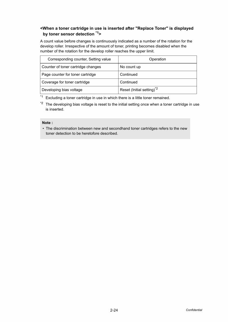
<When a toner cartridge in use is inserted after "Replace Toner" is displayed by toner sensor detection *1>
A count value before changes is continuously indicated as a number of the rotation for the develop roller. Irrespective of the amount of toner, printing becomes disabled when the number of the rotation for the develop roller reaches the upper limit.
*1 Excluding a toner cartridge in use in which there is a little toner remained.*2 The developing bias voltage is reset to the initial setting once when a toner cartridge in use
is inserted.
Corresponding counter, Setting value Operation
Counter of toner cartridge changes No count up
Page counter for toner cartridge Continued
Coverage for toner cartridge Continued
Developing bias voltage Reset (Initial setting)*2
Note :• The discrimination between new and secondhand toner cartridges refers to the new
toner detection to be heretofore described.
2-25 Confidential
3.5 Print
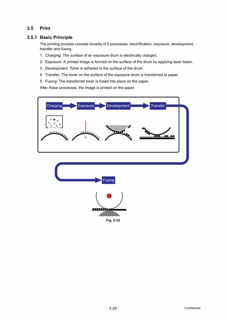
3.5.1 Basic PrincipleThe printing process consists broadly of 5 processes: electrification, exposure, development, transfer and fusing.
1. Charging: The surface of an exposure drum is electrically charged.
2. Exposure: A printed image is formed on the surface of the drum by applying laser beam.
3. Development: Toner is adhered to the surface of the drum.
4. Transfer: The toner on the surface of the exposure drum is transferred to paper.
5. Fusing: The transferred toner is fused into place on the paper.
After these processes, the image is printed on the paper.
Fig. 2-22
Charging Exposure Development Transfer
Fusing
2-26 Confidential
3.5.2 Print Process
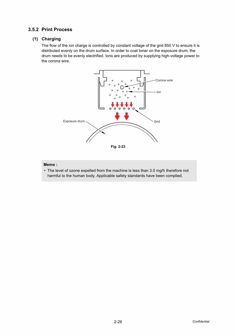
(1) ChargingThe flow of the ion charge is controlled by constant voltage of the grid 850 V to ensure it is distributed evenly on the drum surface. In order to coat toner on the exposure drum, the drum needs to be evenly electrified. Ions are produced by supplying high-voltage power to the corona wire.
Fig. 2-23
Memo :• The level of ozone expelled from the machine is less than 3.0 mg/h therefore not
harmful to the human body. Applicable safety standards have been complied.
Corona wire
Ion
GridExposure drum
2-27 Confidential
(2) ExposureThe laser beam radiated from a laser diode inside the laser unit is concentrated into a constant width by a slit in the CO lens cell and then reflected by a polygon mirror rotating at high speed. The evenly charged exposure drum is irradiated with reflected light and exposed. Surface potential is lowered by such exposure and a printed image is formed.
Fig. 2-24
CO lens Laser diode
Laser unit
Exposure drum
Polygon mirror
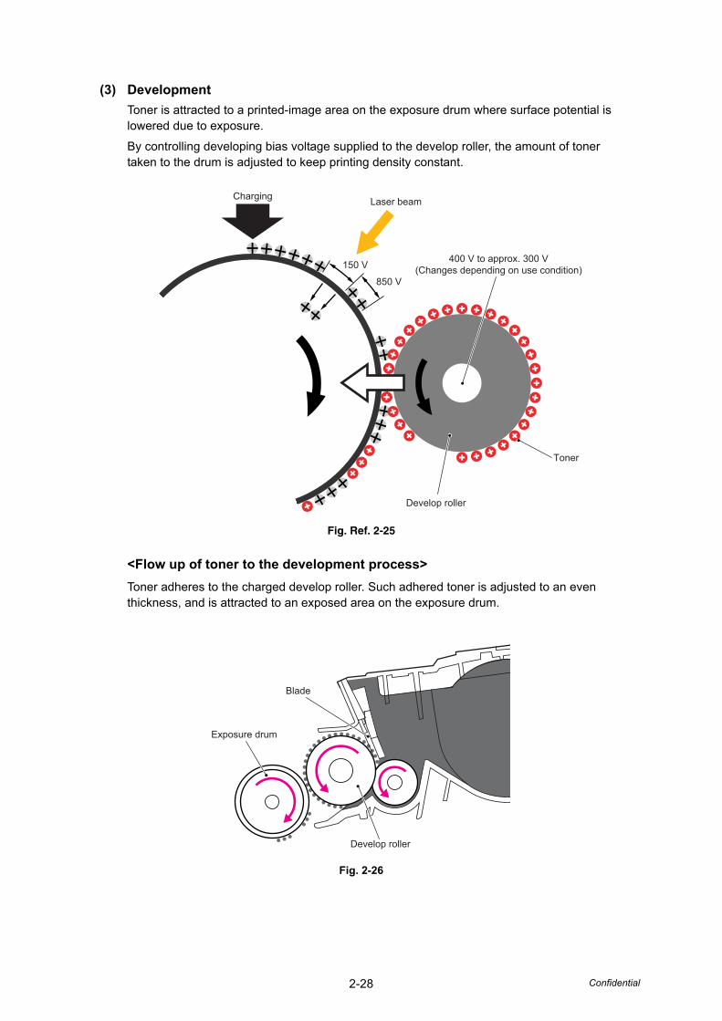
2-28 Confidential
(3) DevelopmentToner is attracted to a printed-image area on the exposure drum where surface potential is lowered due to exposure.
By controlling developing bias voltage supplied to the develop roller, the amount of toner taken to the drum is adjusted to keep printing density constant.
Fig. Ref. 2-25
<Flow up of toner to the development process>Toner adheres to the charged develop roller. Such adhered toner is adjusted to an even thickness, and is attracted to an exposed area on the exposure drum.
Fig. 2-26
Charging
400 V to approx. 300 V(Changes depending on use condition)
Toner
Develop roller
Laser beam
150 V
850 V
Blade
Exposure drum
Develop roller
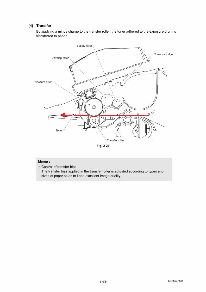
2-29 Confidential
(4) TransferBy applying a minus charge to the transfer roller, the toner adhered to the exposure drum is transferred to paper.
Fig. 2-27
Memo :• Control of transfer bias
The transfer bias applied in the transfer roller is adjusted according to types and sizes of paper so as to keep excellent image quality.
Exposure drum
Transfer roller
Toner
Develop roller
Supply roller
Toner cartridge
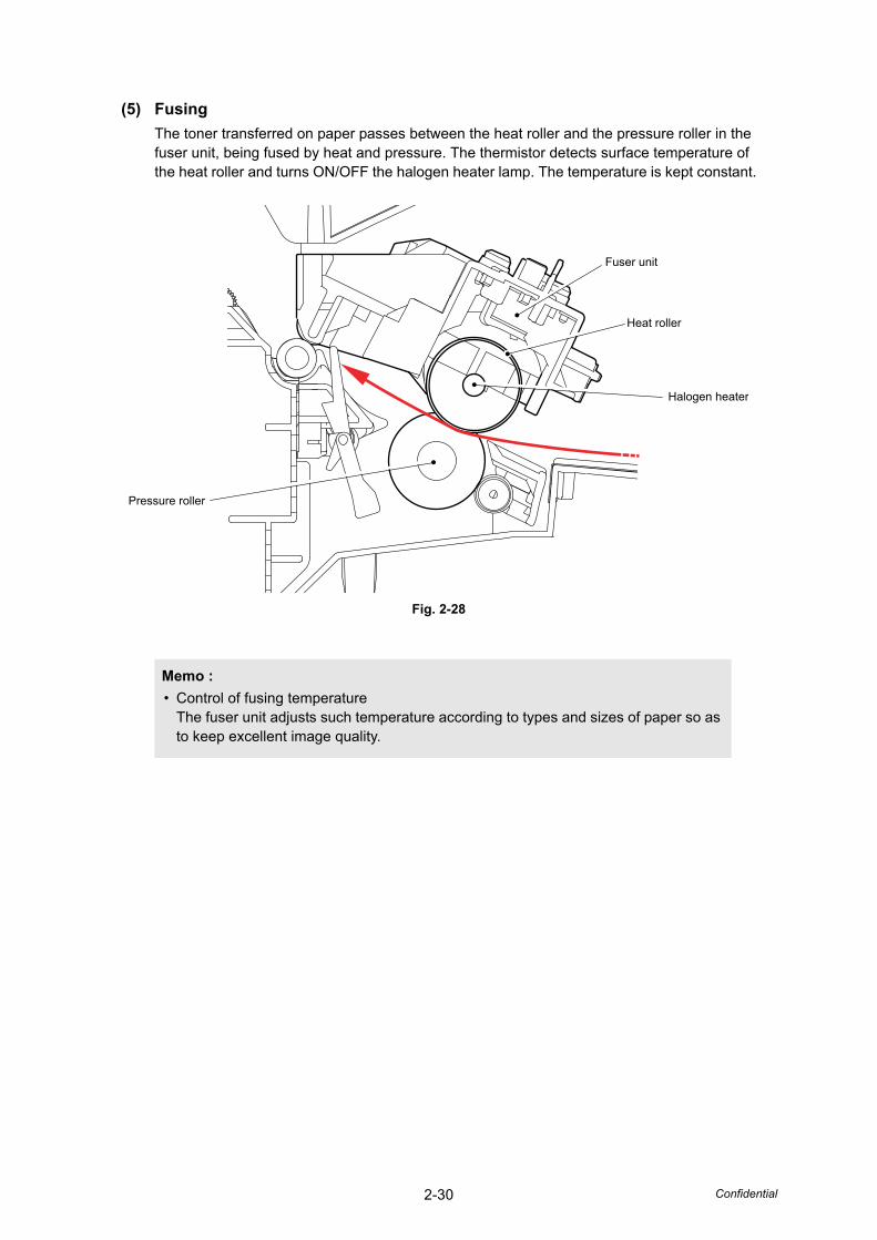
2-30 Confidential
(5) FusingThe toner transferred on paper passes between the heat roller and the pressure roller in the fuser unit, being fused by heat and pressure. The thermistor detects surface temperature of the heat roller and turns ON/OFF the halogen heater lamp. The temperature is kept constant.
Fig. 2-28
Memo :• Control of fusing temperature
The fuser unit adjusts such temperature according to types and sizes of paper so as to keep excellent image quality.
Fuser unit
Heat roller
Halogen heater
Pressure roller
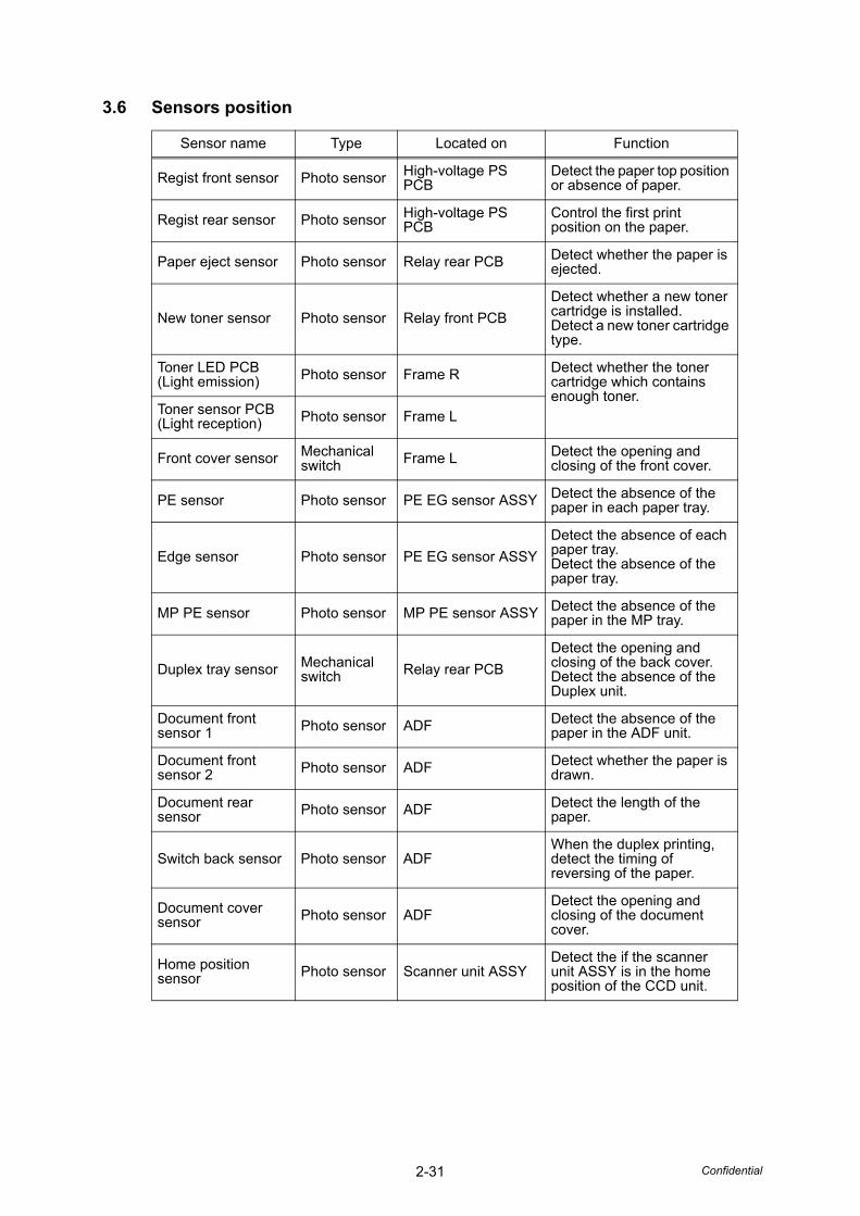
2-31 Confidential
3.6 Sensors position
Sensor name Type Located on Function
Regist front sensor Photo sensor High-voltage PS PCB
Detect the paper top position or absence of paper.
Regist rear sensor Photo sensor High-voltage PS PCB
Control the first print position on the paper.
Paper eject sensor Photo sensor Relay rear PCB Detect whether the paper is ejected.
New toner sensor Photo sensor Relay front PCBDetect whether a new toner cartridge is installed.Detect a new toner cartridge type.
Toner LED PCB(Light emission) Photo sensor Frame R Detect whether the toner
cartridge which contains enough toner.
Toner sensor PCB(Light reception) Photo sensor Frame L
Front cover sensor Mechanical switch Frame L Detect the opening and
closing of the front cover.
PE sensor Photo sensor PE EG sensor ASSY Detect the absence of the paper in each paper tray.
Edge sensor Photo sensor PE EG sensor ASSYDetect the absence of each paper tray.Detect the absence of thepaper tray.
MP PE sensor Photo sensor MP PE sensor ASSY Detect the absence of the paper in the MP tray.
Duplex tray sensor Mechanical switch Relay rear PCB
Detect the opening and closing of the back cover.Detect the absence of the Duplex unit.
Document front sensor 1 Photo sensor ADF Detect the absence of the
paper in the ADF unit.
Document front sensor 2 Photo sensor ADF Detect whether the paper is
drawn.
Document rear sensor Photo sensor ADF Detect the length of the
paper.
Switch back sensor Photo sensor ADFWhen the duplex printing, detect the timing of reversing of the paper.
Document cover sensor Photo sensor ADF
Detect the opening and closing of the document cover.
Home position sensor Photo sensor Scanner unit ASSY
Detect the if the scanner unit ASSY is in the home position of the CCD unit.
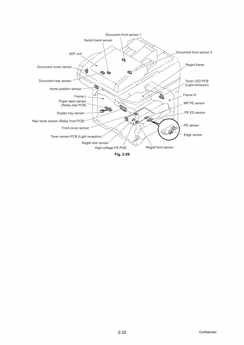
2-32 Confidential
Fig. 2-29
Document front sensor 1
Regist front sensor
Edge sensor
PE sensor
PE EG sensor
MP PE sensor
Frame R
Toner LED PCB(Light emission)
Regist frame
Document front sensor 2
Switch back sensor
ADF unit
Document cover sensor
Document rear sensor
Home position sensor
Frame LPaper eject sensor
(Relay rear PCB)
Duplex tray sensor
New toner sensor (Relay front PCB)
Front cover sensor
Toner sensor PCB (Light reception)
Regist rear sensorHigh-voltage PS PCB

CHAPTER 3ERROR INDICATION AND
TROUBLESHOOTING
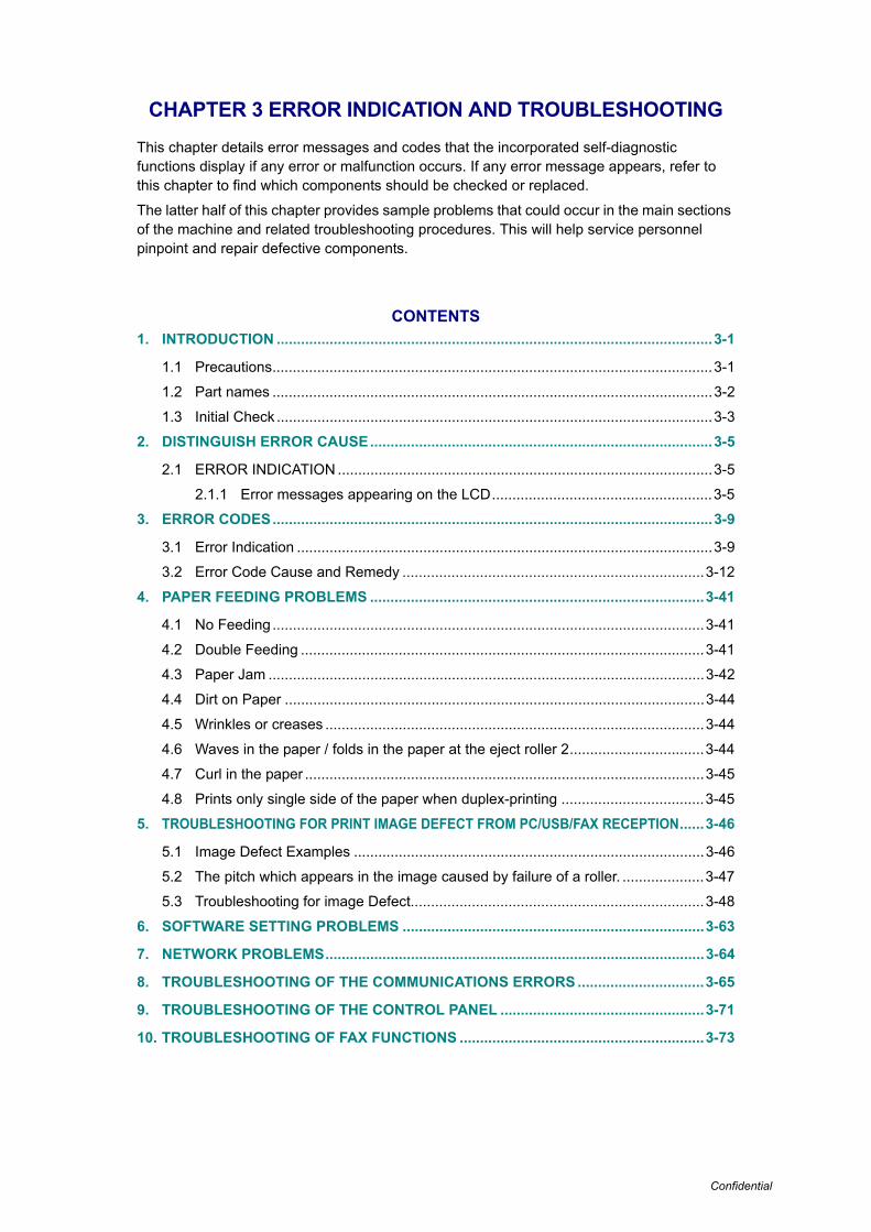
Confidential
CHAPTER 3 ERROR INDICATION AND TROUBLESHOOTING
This chapter details error messages and codes that the incorporated self-diagnostic functions display if any error or malfunction occurs. If any error message appears, refer to this chapter to find which components should be checked or replaced.
The latter half of this chapter provides sample problems that could occur in the main sections of the machine and related troubleshooting procedures. This will help service personnel pinpoint and repair defective components.
CONTENTS1. INTRODUCTION ...........................................................................................................3-1
1.1 Precautions............................................................................................................3-1
1.2 Part names ............................................................................................................3-2
1.3 Initial Check ...........................................................................................................3-3
2. DISTINGUISH ERROR CAUSE....................................................................................3-5
2.1 ERROR INDICATION ............................................................................................3-5
2.1.1 Error messages appearing on the LCD......................................................3-5
3. ERROR CODES............................................................................................................3-9
3.1 Error Indication ......................................................................................................3-9
3.2 Error Code Cause and Remedy ..........................................................................3-12
4. PAPER FEEDING PROBLEMS ..................................................................................3-41
4.1 No Feeding ..........................................................................................................3-41
4.2 Double Feeding ...................................................................................................3-41
4.3 Paper Jam ...........................................................................................................3-42
4.4 Dirt on Paper .......................................................................................................3-44
4.5 Wrinkles or creases .............................................................................................3-44
4.6 Waves in the paper / folds in the paper at the eject roller 2.................................3-44
4.7 Curl in the paper ..................................................................................................3-45
4.8 Prints only single side of the paper when duplex-printing ...................................3-45
5. TROUBLESHOOTING FOR PRINT IMAGE DEFECT FROM PC/USB/FAX RECEPTION......3-46
5.1 Image Defect Examples ......................................................................................3-46
5.2 The pitch which appears in the image caused by failure of a roller. ....................3-47
5.3 Troubleshooting for image Defect........................................................................3-48
6. SOFTWARE SETTING PROBLEMS ..........................................................................3-63
7. NETWORK PROBLEMS.............................................................................................3-64
8. TROUBLESHOOTING OF THE COMMUNICATIONS ERRORS ...............................3-65
9. TROUBLESHOOTING OF THE CONTROL PANEL ..................................................3-71
10. TROUBLESHOOTING OF FAX FUNCTIONS ............................................................3-73

Confidential
11. DOCUMENT FEEDING PROBLEMS..........................................................................3-77
11.1 No Feeding ..........................................................................................................3-77
11.2 Double Feeding ...................................................................................................3-78
11.3 Paper Jam ...........................................................................................................3-78
11.4 Wrinkles...............................................................................................................3-80
12. SCANNING IMAGE DEFECT TROUBLESHOOTING................................................3-81
12.1 Image Defect Examples ......................................................................................3-81
12.2 Troubleshooting Image Defect ............................................................................3-81
13. OTHERS PROBLEMS ................................................................................................3-85
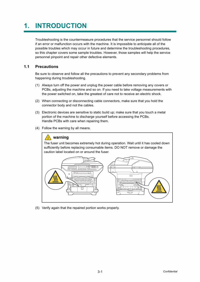
3-1 Confidential
1. INTRODUCTION
Troubleshooting is the countermeasure procedures that the service personnel should follow if an error or malfunction occurs with the machine. It is impossible to anticipate all of the possible troubles which may occur in future and determine the troubleshooting procedures, so this chapter covers some sample troubles. However, those samples will help the service personnel pinpoint and repair other defective elements.
1.1 PrecautionsBe sure to observe and follow all the precautions to prevent any secondary problems from happening during troubleshooting.
(1) Always turn off the power and unplug the power cable before removing any covers or PCBs, adjusting the machine and so on. If you need to take voltage measurements with the power switched on, take the greatest of care not to receive an electric shock.
(2) When connecting or disconnecting cable connectors, make sure that you hold the connector body and not the cables.
(3) Electronic devices are sensitive to static build up; make sure that you touch a metal portion of the machine to discharge yourself before accessing the PCBs.Handle PCBs with care when repairing them.
(4) Follow the warning by all means.
(5) Verify again that the repaired portion works properly.
warningThe fuser unit becomes extremely hot during operation. Wait until it has cooled down sufficiently before replacing consumable items. DO NOT remove or damage the caution label located on or around the fuser.
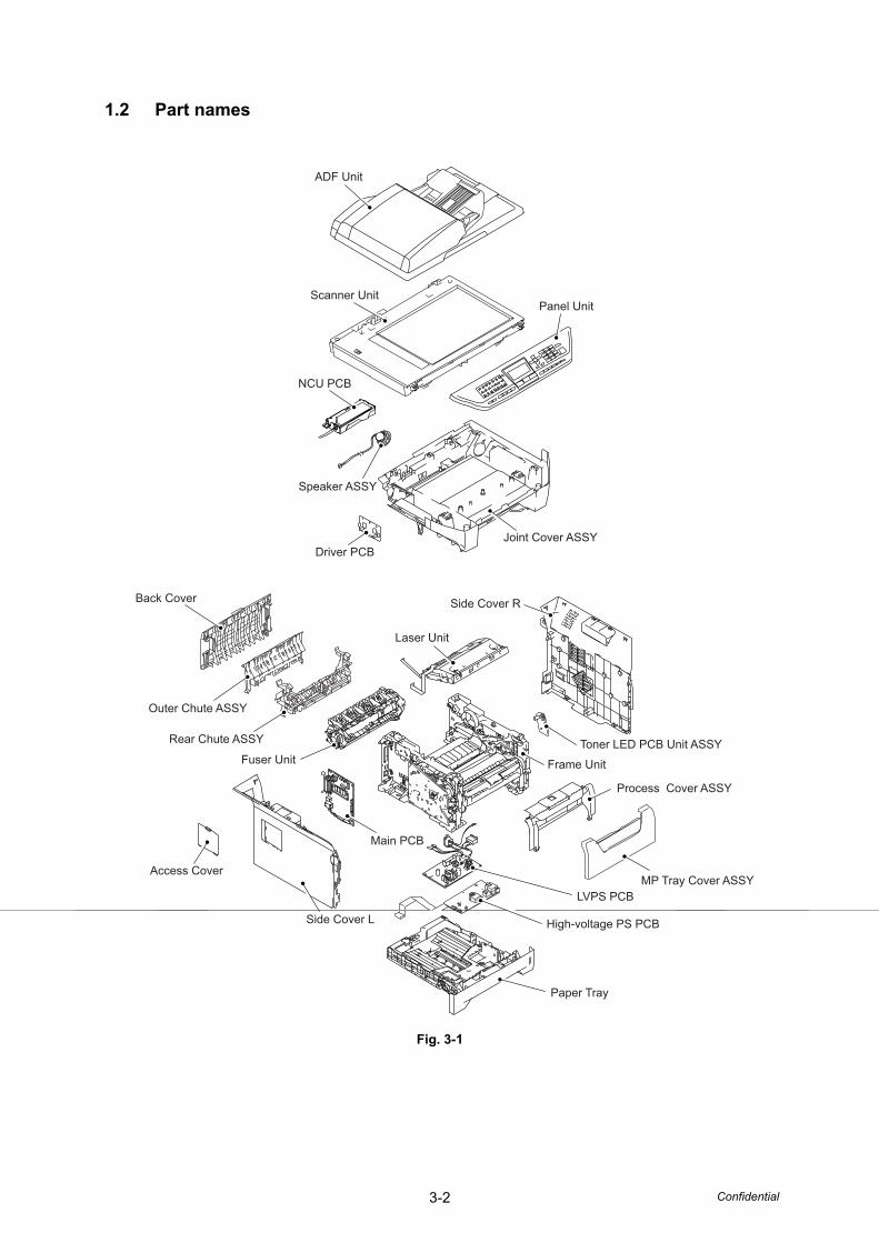
3-2 Confidential
1.2 Part names
Fig. 3-1
Driver PCBJoint Cover ASSY
NCU PCB
Scanner Unit
ADF Unit
Panel Unit
Speaker ASSY
Back Cover
Outer Chute ASSY
Rear Chute ASSY
Fuser Unit
Main PCB
Access Cover
Side Cover L
Side Cover R
Laser Unit
Toner LED PCB Unit ASSY
Paper Tray
High-voltage PS PCB
LVPS PCBMP Tray Cover ASSY
Process Cover ASSY
Frame Unit
3-3 Confidential
1.3 Initial CheckCheck the following items before attempting to repair the machine.
■ Operating Environment
(1) Put your machine on a flat, stable surface such as a desk that is free of vibration and shocks.
(2) Use the machine in a well-ventilated room; use the machine within the following ranges of temperature and humidity: temperature between 10°C and 32.5°C (50°F to 90.5°F), and the relative humidity is maintained between 20% and 80%.
(3) The machine is not exposed to direct sunlight, excessive heat, moisture, or dust.
■ Power Supply
(1) The AC input power supply described on the rating plate of the machine should be within ±10% of the rated voltage.
(2) The AC input power supply is within the regulated value.
(3) The cables and harnesses are connected correctly.
(4) The fuses are not blown.
■ Paper
(1) A recommended type of paper is being used. (Refer to "2.6.2 Media specifications" in Chapter 1.)
(2) The paper is not damp.
(3) The paper is not short-grained paper or acid paper.
■ Consumable Parts
(1) The drum unit (including the toner cartridge) is installed correctly.
■ Others
(1) Condensation
When the machine is moved from a cold place into a warm room, condensation may occur inside the machine, causing various problems as listed below.
• Condensation on the optical surfaces such as the scanner window, lenses, the reflection mirror and the protection glass may cause the print image to be light.
• If the exposure drum is cold, the electrical resistance of the photosensitive layer is increased, making it impossible to obtain the correct contrast when printing.
• Condensation on the charge unit may cause corona charge leakage.
• Condensation on the plate and separation pad may cause paper feed failures.
If condensation has occurred, activate the Drum condensation countermeasure mode.( "5.3 Drum condensation countermeasure mode" in Chapter 6.)
If the drum unit is unpacked soon after it is moved from a cold place to a warm room, condensation may occur inside the unit which may cause incorrect images. Instruct the end user to allow the unit to come to room temperature before unpacking it. This will take one or two hours.

3-4 Confidential
(2) Cleaning
Use a soft dry cloth.
warningDO NOT use flammable substances such as alcohol, benzine, thinner or any type of spray to clean the inside or outside of the machine. Doing this may cause a fire or electrical shock.
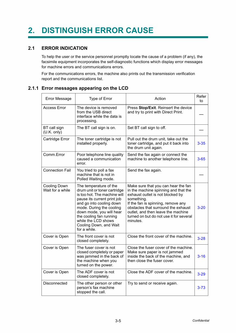
3-5 Confidential
2. DISTINGUISH ERROR CAUSE
2.1 ERROR INDICATIONTo help the user or the service personnel promptly locate the cause of a problem (if any), the facsimile equipment incorporates the self-diagnostic functions which display error messages for machine errors and communications errors.
For the communications errors, the machine also prints out the transmission verification report and the communications list.
2.1.1 Error messages appearing on the LCD
Error Message Type of Error Action Refer to
Access Error The device is removed from the USB direct interface while the data is processing.
Press Stop/Exit. Reinsert the device and try to print with Direct Print. -
BT call sign(U.K. only)
The BT call sign is on. Set BT call sign to off. -
Cartridge Error The toner cartridge is not installed properly.
Pull out the drum unit, take out the toner cartridge, and put it back into the drum unit again.
3-35
Comm.Error Poor telephone line quality caused a communication error.
Send the fax again or connect the machine to another telephone line. 3-65
Connection Fail You tried to poll a fax machine that is not in Polled Waiting mode.
Send the fax again.-
Cooling Down Wait for a while
The temperature of the drum unit or toner cartridge is too hot. The machine will pause its current print job and go into cooling down mode. During the cooling down mode, you will hear the cooling fan running while the LCD shows Cooling Down, and Wait for a while.
Make sure that you can hear the fan in the machine spinning and that the exhaust outlet is not blocked by something.If the fan is spinning, remove any obstacles that surround the exhaust outlet, and then leave the machine turned on but do not use it for several minutes.
3-20
Cover is Open The front cover is not closed completely.
Close the front cover of the machine. 3-28
Cover is Open The fuser cover is not closed completely or paper was jammed in the back of the machine when you turned on the power.
Close the fuser cover of the machine.Make sure paper is not jammed inside the back of the machine, and then close the fuser cover.
3-16
Cover is Open The ADF cover is not closed completely.
Close the ADF cover of the machine. 3-29
Disconnected The other person or other person’s fax machine stopped the call.
Try to send or receive again.3-73
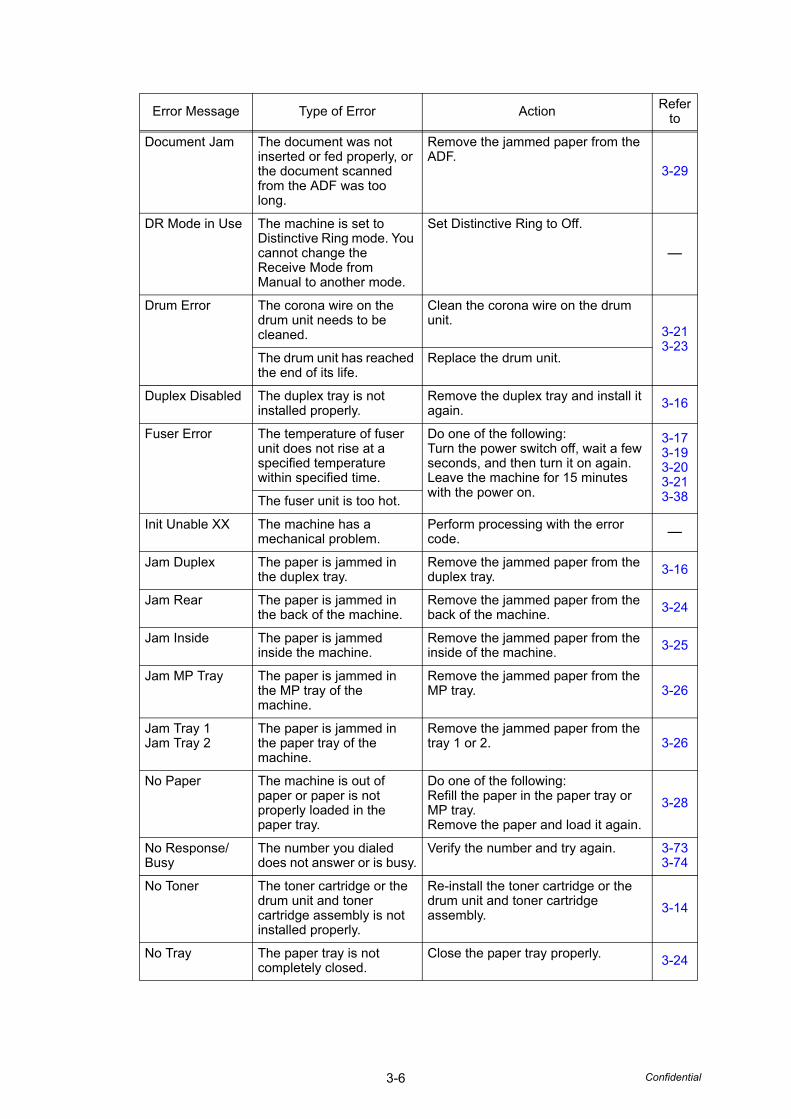
3-6 Confidential
Document Jam The document was not inserted or fed properly, or the document scanned from the ADF was too long.
Remove the jammed paper from the ADF.
3-29
DR Mode in Use The machine is set to Distinctive Ring mode. You cannot change the Receive Mode from Manual to another mode.
Set Distinctive Ring to Off.
-
Drum Error The corona wire on the drum unit needs to be cleaned.
Clean the corona wire on the drum unit.
3-213-23
The drum unit has reached the end of its life.
Replace the drum unit.
Duplex Disabled The duplex tray is not installed properly.
Remove the duplex tray and install it again. 3-16
Fuser Error The temperature of fuser unit does not rise at a specified temperature within specified time.
Do one of the following:Turn the power switch off, wait a few seconds, and then turn it on again. Leave the machine for 15 minutes with the power on.
3-173-193-203-213-38The fuser unit is too hot.
Init Unable XX The machine has a mechanical problem.
Perform processing with the error code. -
Jam Duplex The paper is jammed in the duplex tray.
Remove the jammed paper from the duplex tray. 3-16
Jam Rear The paper is jammed in the back of the machine.
Remove the jammed paper from the back of the machine. 3-24
Jam Inside The paper is jammed inside the machine.
Remove the jammed paper from the inside of the machine. 3-25
Jam MP Tray The paper is jammed in the MP tray of the machine.
Remove the jammed paper from the MP tray. 3-26
Jam Tray 1Jam Tray 2
The paper is jammed in the paper tray of the machine.
Remove the jammed paper from the tray 1 or 2. 3-26
No Paper The machine is out of paper or paper is not properly loaded in the paper tray.
Do one of the following:Refill the paper in the paper tray or MP tray.Remove the paper and load it again.
3-28
No Response/Busy
The number you dialed does not answer or is busy.
Verify the number and try again. 3-733-74
No Toner The toner cartridge or the drum unit and toner cartridge assembly is not installed properly.
Re-install the toner cartridge or the drum unit and toner cartridge assembly. 3-14
No Tray The paper tray is not completely closed.
Close the paper tray properly. 3-24
Error Message Type of Error Action Refer to
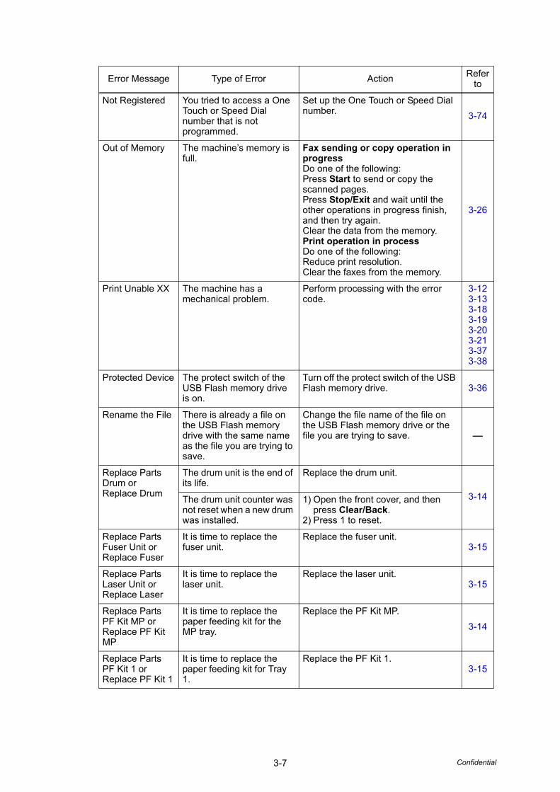
3-7 Confidential
Not Registered You tried to access a One Touch or Speed Dial number that is not programmed.
Set up the One Touch or Speed Dial number. 3-74
Out of Memory The machine’s memory is full.
Fax sending or copy operation inprogressDo one of the following:Press Start to send or copy the scanned pages.Press Stop/Exit and wait until the other operations in progress finish, and then try again.Clear the data from the memory.Print operation in processDo one of the following:Reduce print resolution.Clear the faxes from the memory.
3-26
Print Unable XX The machine has a mechanical problem.
Perform processing with the error code.
3-123-133-183-193-203-213-373-38
Protected Device The protect switch of the USB Flash memory drive is on.
Turn off the protect switch of the USB Flash memory drive. 3-36
Rename the File There is already a file on the USB Flash memory drive with the same name as the file you are trying to save.
Change the file name of the file on the USB Flash memory drive or the file you are trying to save. -
Replace Parts Drum or Replace Drum
The drum unit is the end of its life.
Replace the drum unit.
3-14The drum unit counter was not reset when a new drum was installed.
1) Open the front cover, and then press Clear/Back.
2) Press 1 to reset.
Replace Parts Fuser Unit or Replace Fuser
It is time to replace the fuser unit.
Replace the fuser unit.3-15
Replace Parts Laser Unit or Replace Laser
It is time to replace the laser unit.
Replace the laser unit.3-15
Replace Parts PF Kit MP or Replace PF Kit MP
It is time to replace the paper feeding kit for the MP tray.
Replace the PF Kit MP.3-14
Replace Parts PF Kit 1 or Replace PF Kit 1
It is time to replace the paper feeding kit for Tray 1.
Replace the PF Kit 1.3-15
Error Message Type of Error Action Refer to
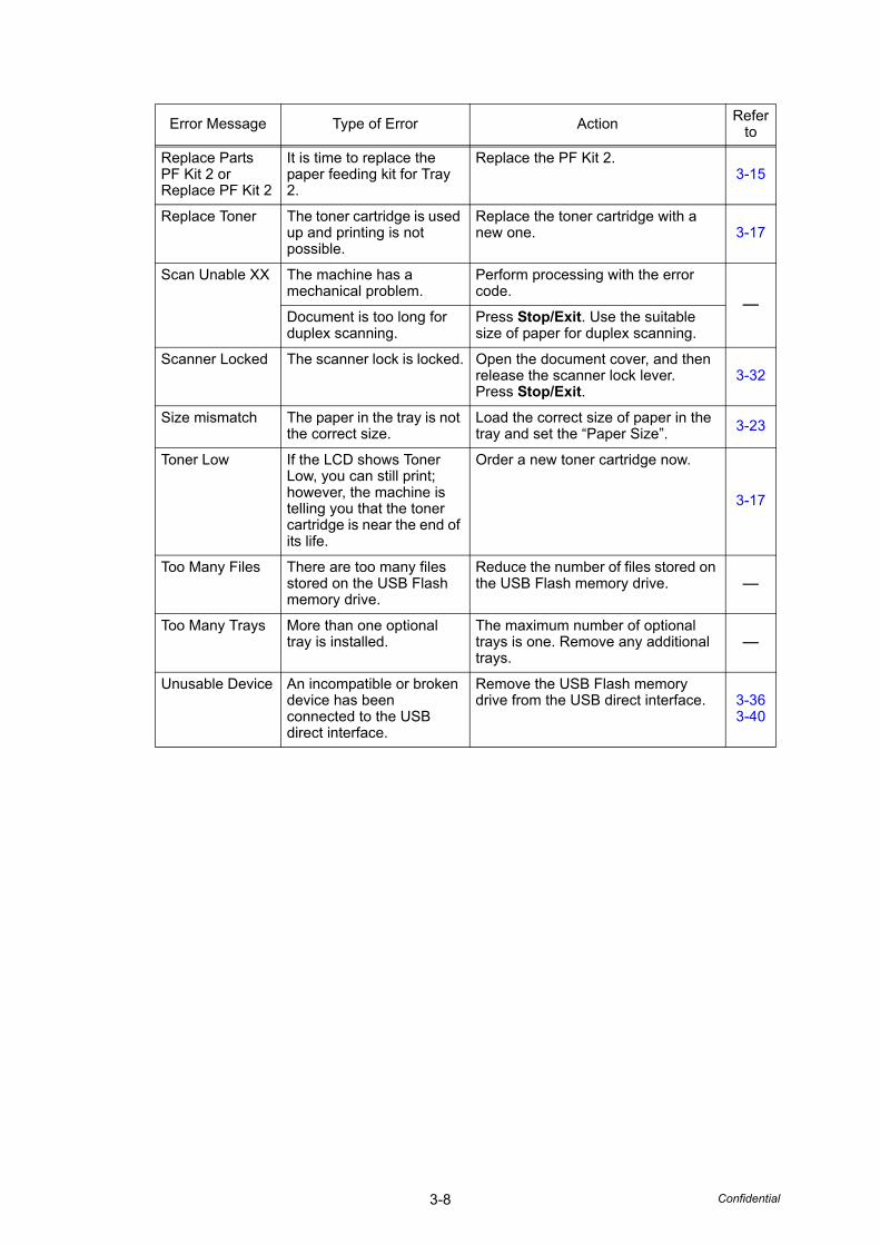
3-8 Confidential
Replace Parts PF Kit 2 or Replace PF Kit 2
It is time to replace the paper feeding kit for Tray 2.
Replace the PF Kit 2.3-15
Replace Toner The toner cartridge is used up and printing is not possible.
Replace the toner cartridge with a new one. 3-17
Scan Unable XX The machine has a mechanical problem.
Perform processing with the error code.
-Document is too long for duplex scanning.
Press Stop/Exit. Use the suitable size of paper for duplex scanning.
Scanner Locked The scanner lock is locked. Open the document cover, and then release the scanner lock lever.Press Stop/Exit.
3-32
Size mismatch The paper in the tray is not the correct size.
Load the correct size of paper in the tray and set the “Paper Size”. 3-23
Toner Low If the LCD shows Toner Low, you can still print; however, the machine is telling you that the toner cartridge is near the end of its life.
Order a new toner cartridge now.
3-17
Too Many Files There are too many files stored on the USB Flash memory drive.
Reduce the number of files stored on the USB Flash memory drive. -
Too Many Trays More than one optional tray is installed.
The maximum number of optional trays is one. Remove any additional trays.
-
Unusable Device An incompatible or broken device has been connected to the USB direct interface.
Remove the USB Flash memory drive from the USB direct interface. 3-36
3-40
Error Message Type of Error Action Refer to
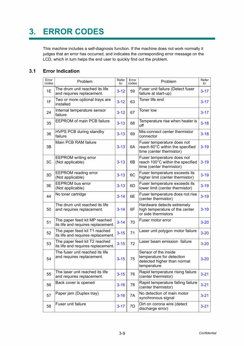
3-9 Confidential
3. ERROR CODES
This machine includes a self-diagnosis function. If the machine does not work normally it judges that an error has occurred, and indicates the corresponding error message on the LCD, which in turn helps the end user to quickly find out the problem.
3.1 Error IndicationError codes Problem Refer
to:Error codes Problem Refer
to:
1E The drum unit reached its life and requires replacement. 3-12 59 Fuser unit failure (Detect fuser
failure at start-up) 3-17
1F Two or more optional trays are installed 3-12 63 Toner life end 3-17
24 Internal temperature sensor failure 3-12 67 Toner low 3-17
35 EEPROM of main PCB failure 3-13 68 Temperature rise when heater is off 3-18
36 HVPS PCB during standby failure 3-13 69 Mis-connect center thermistor
connector 3-18
3BMain PCB RAM failure
3-13 6AFuser temperature does not reach 60°C within the specified time (center thermistor)
3-19
3CEEPROM writing error(Not applicable) 3-13 6B
Fuser temperature does not reach 100°C within the specified time (center thermistor)
3-19
3D EEPROM reading error(Not applicable) 3-13 6C Fuser temperature exceeds its
higher limit (center thermistor) 3-19
3E EEPROM bus error(Not applicable) 3-13 6D Fuser temperature exceeds its
lower limit (center thermistor) 3-19
44 No toner cartridge 3-14 6E Fuser temperature does not rise (center thermistor) 3-19
50The drum unit reached its life and requires replacement. 3-14 6F
Hardware detects extremely high temperature of the center or side thermistors
3-19
51 The paper feed kit MP reached its life and requires replacement. 3-14 70 Fuser motor error 3-20
52 The paper feed kit T1 reached its life and requires replacement. 3-15 71 Laser unit polygon motor failure 3-20
53 The paper feed kit T2 reached its life and requires replacement. 3-15 72 Laser beam emission failure 3-20
54The fuser unit reached its life and requires replacement. 3-15 75
Sensor of the inside temperature for detection detected higher than normal temperature
3-20
55 The laser unit reached its life and requires replacement. 3-15 76 Rapid temperature rising failure
(center thermistor) 3-21
56 Back cover is opened 3-16 78 Rapid temperature falling failure(center thermistor) 3-21
57 Paper jam (Duplex tray) 3-16 7A No detection of main motor synchronous signal 3-21
58 Fuser unit failure 3-17 7D Dirt on corona wire (detect discharge error) 3-21
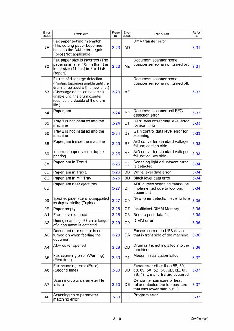
3-10 Confidential
Error codes Problem Refer
to:Error codes Problem Refer
to:
7FFax paper setting mismatch (The setting paper becomes besides the A4/Letter/Legal/Folio) (Not applicable)
3-23 ADDMA transfer error
3-31
80Fax paper size is incorrect (The paper is smaller 10mm than the letter size (11inch) in Fax List/Report)
3-23 AEDocument scanner home position sensor is not turned on. 3-31
83
Failure of discharge detection(Printing becomes unable until the drum is replaced with a new one.)(Discharge detection becomes unable until the drum counter reaches the double of the drum life.)
3-23 AF
Document scanner home position sensor is not turned off.
3-32
84 Paper jam 3-24 B0 Document scanner unit FFC detection error 3-32
85 Tray 1 is not installed into the machine 3-24 B1 Dark level offset data level error
for scanning 3-33
86 Tray 2 is not installed into the machine 3-24 B2 Gain control data level error for
scanning 3-33
88 Paper jam inside the machine 3-25 B7 A/D converter standard voltage failure; at High side 3-33
89 Incorrect paper size in duplex printing 3-25 B8 A/D converter standard voltage
failure; at Low side 3-33
8A Paper jam in Tray 1 3-26 B9 Scanning light adjustment error is detected 3-34
8B Paper jam in Tray 2 3-26 BB White level data error 3-348C Paper jam in MP Tray 3-26 BD Black level data error 3-34
8DPaper jam near eject tray
3-27 BFADF duplex scanning cannot be implemented due to too long document
3-34
99 Specified paper size is not supported for duplex printing (Duplex) 3-27 C0 New toner detection lever failure 3-35
9F Paper empty 3-28 C7 Insufficient DIMM Memory 3-35A1 Front cover opened 3-28 C8 Secure print data full 3-35
A2 During scanning, 90 cm or longer of a document is detected 3-29 C9 DIMM error 3-36
A3Document rear sensor is not turned on when feeding the document
3-29 CAExcess current to USB device that is front side of the machine 3-36
A4 ADF cover opened 3-29 CD Drum unit is not installed into the machine 3-36
A5 Fax scanning error (Warning)(First time) 3-30 D1 Modem initialization failed 3-37
A6Fax scanning error (Error) (Second time) 3-30 DD
Fuser error other than 58, 59, 68, 69, 6A, 6B, 6C, 6D, 6E, 6F, 76, 78, DE and E2 are occurred
3-37
A7Scanning color parameter file failure 3-30 DE
Central temperature of heat roller detected the temperature that was lower than 60°C)
3-37
A8 Scanning color parameter matching error 3-30 E0 Program error 3-37

3-11 Confidential
Error codes Problem Refer
to:Error codes Problem Refer
to:
E1 Main PCB failure 3-38 EF LVPS PCB failure 3-39
E2 Central temperature of heat roller exceeds 280°C 3-38 F8 Battery connection error 3-39
E6 EEPROM error 3-38 F9 EEPROM customizing code error 3-39
EB The data reading error for E2PROM 3-38 FF Excess current to USB HOST
PCB error 3-40
EC Fuser fan failure 3-39
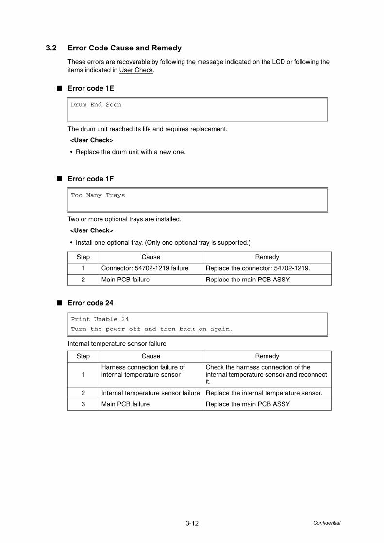
3-12 Confidential
3.2 Error Code Cause and RemedyThese errors are recoverable by following the message indicated on the LCD or following the items indicated in User Check.
■ Error code 1E
The drum unit reached its life and requires replacement.
■ Error code 1F
Two or more optional trays are installed.
■ Error code 24
Internal temperature sensor failure
Drum End Soon
<User Check>
• Replace the drum unit with a new one.
Too Many Trays
<User Check>
• Install one optional tray. (Only one optional tray is supported.)
Step Cause Remedy
1 Connector: 54702-1219 failure Replace the connector: 54702-1219.
2 Main PCB failure Replace the main PCB ASSY.
Print Unable 24
Turn the power off and then back on again.
Step Cause Remedy
1Harness connection failure of internal temperature sensor
Check the harness connection of the internal temperature sensor and reconnect it.
2 Internal temperature sensor failure Replace the internal temperature sensor.
3 Main PCB failure Replace the main PCB ASSY.
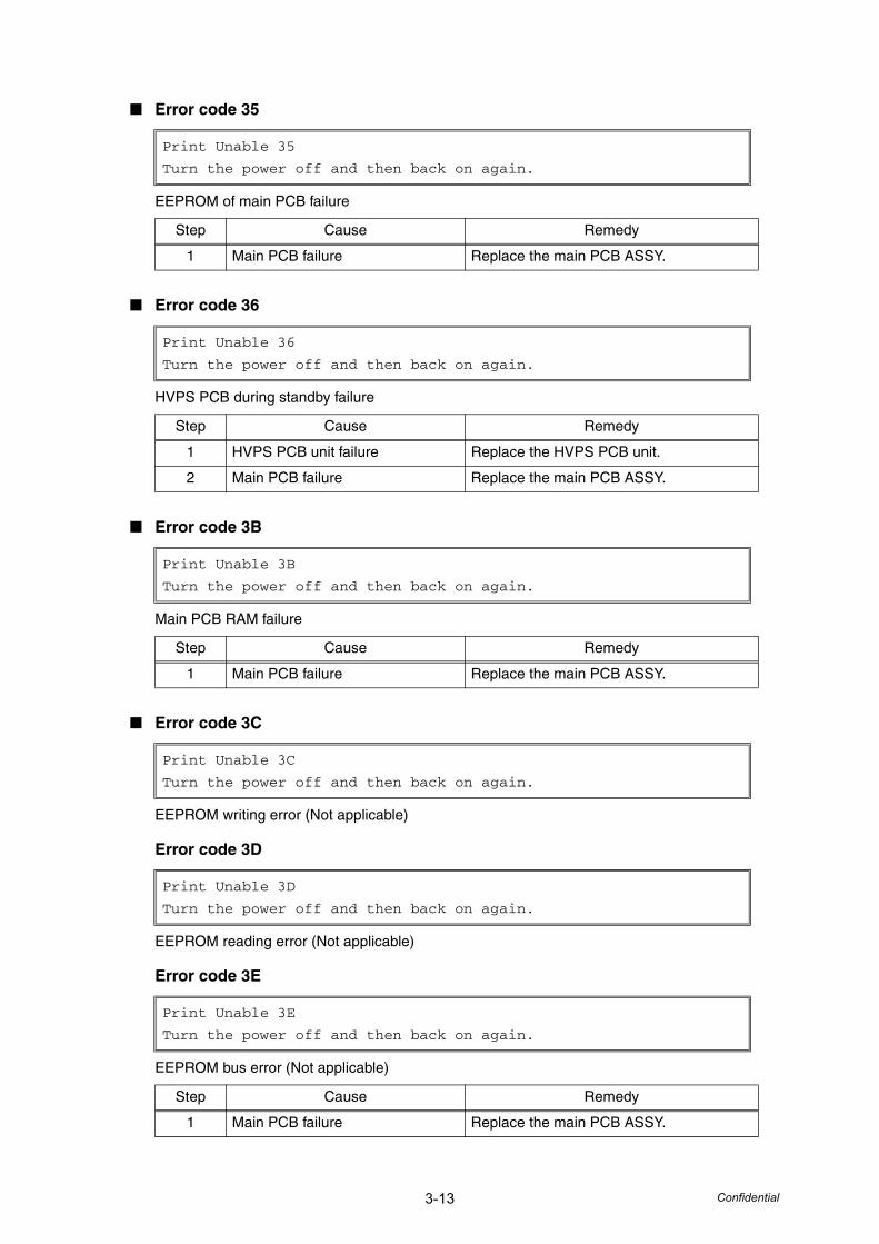
3-13 Confidential
■ Error code 35
EEPROM of main PCB failure
■ Error code 36
HVPS PCB during standby failure
■ Error code 3B
Main PCB RAM failure
■ Error code 3C
EEPROM writing error (Not applicable)
Error code 3D
EEPROM reading error (Not applicable)
Error code 3E
EEPROM bus error (Not applicable)
Print Unable 35
Turn the power off and then back on again.
Step Cause Remedy
1 Main PCB failure Replace the main PCB ASSY.
Print Unable 36
Turn the power off and then back on again.
Step Cause Remedy
1 HVPS PCB unit failure Replace the HVPS PCB unit.
2 Main PCB failure Replace the main PCB ASSY.
Print Unable 3B
Turn the power off and then back on again.
Step Cause Remedy
1 Main PCB failure Replace the main PCB ASSY.
Print Unable 3C
Turn the power off and then back on again.
Print Unable 3D
Turn the power off and then back on again.
Print Unable 3E
Turn the power off and then back on again.
Step Cause Remedy
1 Main PCB failure Replace the main PCB ASSY.
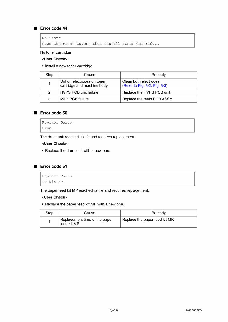
3-14 Confidential
■ Error code 44
No toner cartridge
■ Error code 50
The drum unit reached its life and requires replacement.
■ Error code 51
The paper feed kit MP reached its life and requires replacement.
No Toner
Open the Front Cover, then install Toner Cartridge.
<User Check>
• Install a new toner cartridge.
Step Cause Remedy
1 Dirt on electrodes on toner cartridge and machine body
Clean both electrodes.(Refer to Fig. 3-2, Fig. 3-3)
2 HVPS PCB unit failure Replace the HVPS PCB unit.
3 Main PCB failure Replace the main PCB ASSY.
Replace Parts
Drum
<User Check>
• Replace the drum unit with a new one.
Replace Parts
PF Kit MP
<User Check>
• Replace the paper feed kit MP with a new one.
Step Cause Remedy
1 Replacement time of the paper feed kit MP
Replace the paper feed kit MP.
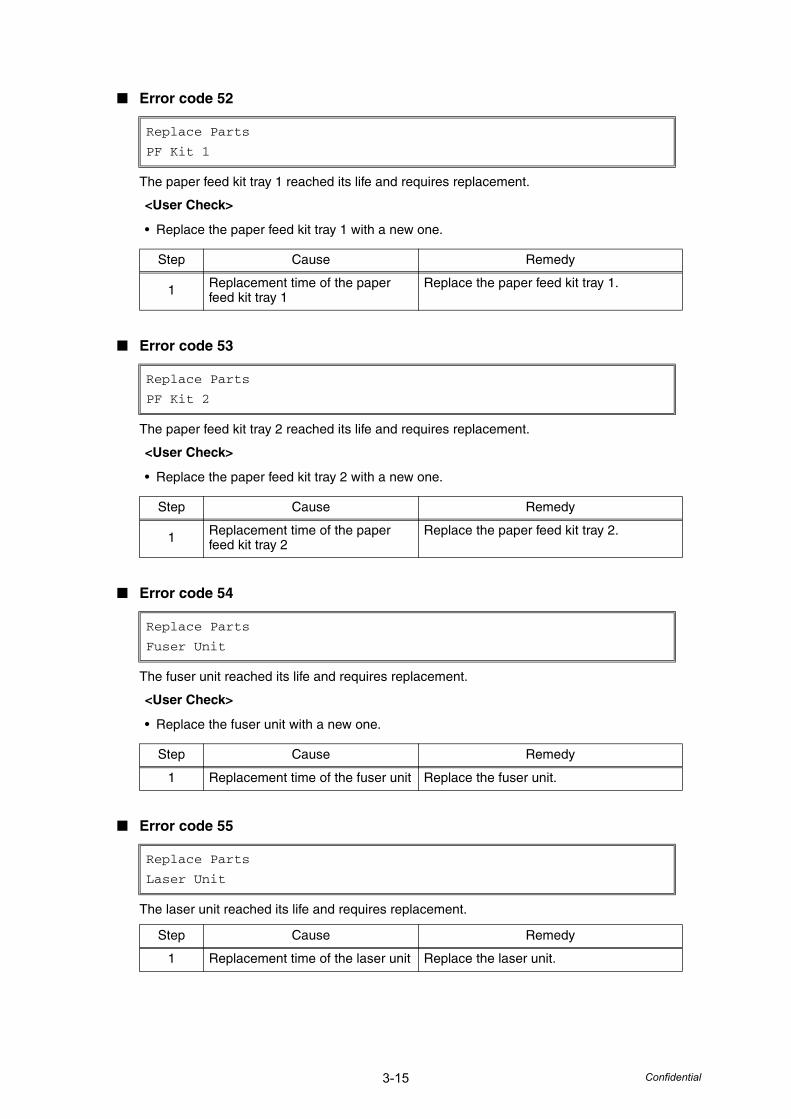
3-15 Confidential
■ Error code 52
The paper feed kit tray 1 reached its life and requires replacement.
■ Error code 53
The paper feed kit tray 2 reached its life and requires replacement.
■ Error code 54
The fuser unit reached its life and requires replacement.
■ Error code 55
The laser unit reached its life and requires replacement.
Replace Parts
PF Kit 1
<User Check>
• Replace the paper feed kit tray 1 with a new one.
Step Cause Remedy
1 Replacement time of the paper feed kit tray 1
Replace the paper feed kit tray 1.
Replace Parts
PF Kit 2
<User Check>
• Replace the paper feed kit tray 2 with a new one.
Step Cause Remedy
1 Replacement time of the paper feed kit tray 2
Replace the paper feed kit tray 2.
Replace Parts
Fuser Unit
<User Check>
• Replace the fuser unit with a new one.
Step Cause Remedy
1 Replacement time of the fuser unit Replace the fuser unit.
Replace Parts
Laser Unit
Step Cause Remedy
1 Replacement time of the laser unit Replace the laser unit.
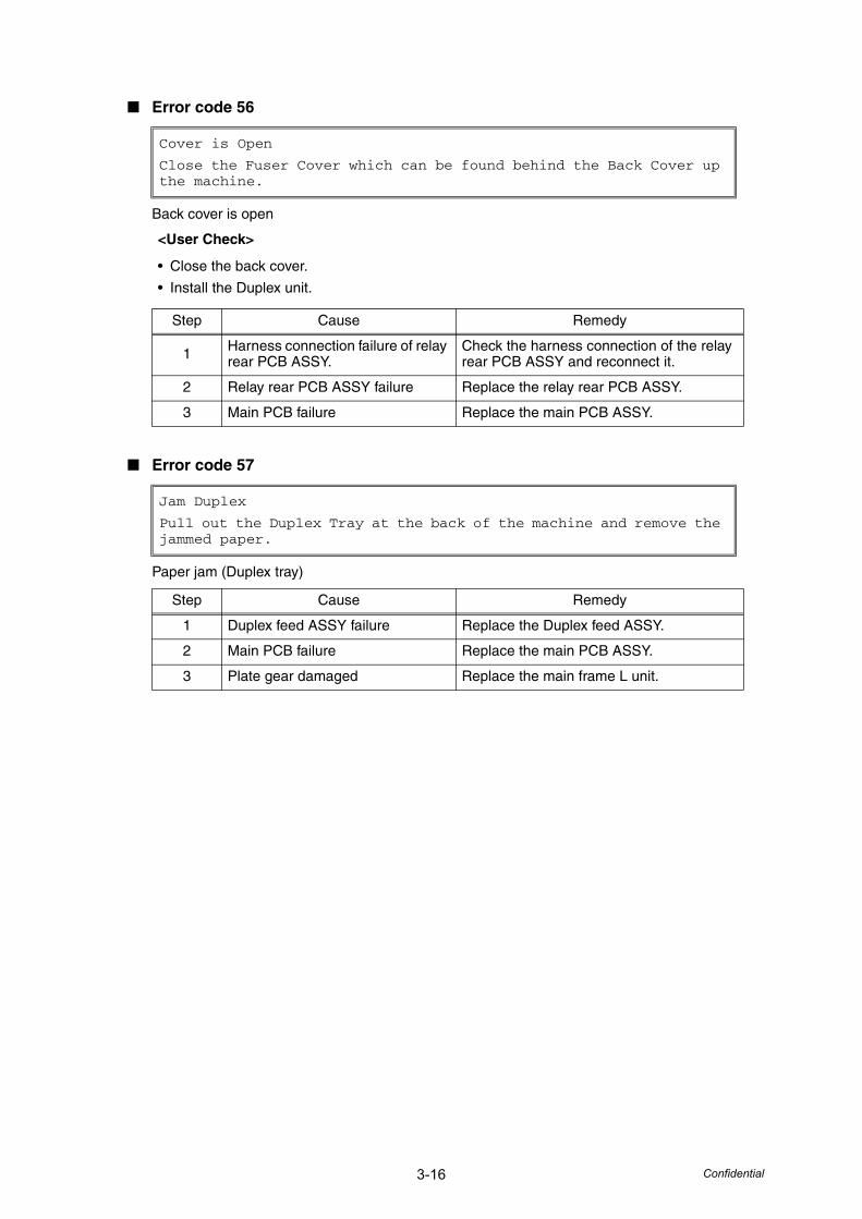
3-16 Confidential
■ Error code 56
Back cover is open
■ Error code 57
Paper jam (Duplex tray)
Cover is Open
Close the Fuser Cover which can be found behind the Back Cover up the machine.
<User Check>
• Close the back cover.
• Install the Duplex unit.
Step Cause Remedy
1 Harness connection failure of relay rear PCB ASSY.
Check the harness connection of the relay rear PCB ASSY and reconnect it.
2 Relay rear PCB ASSY failure Replace the relay rear PCB ASSY.
3 Main PCB failure Replace the main PCB ASSY.
Jam Duplex
Pull out the Duplex Tray at the back of the machine and remove the jammed paper.
Step Cause Remedy
1 Duplex feed ASSY failure Replace the Duplex feed ASSY.
2 Main PCB failure Replace the main PCB ASSY.
3 Plate gear damaged Replace the main frame L unit.
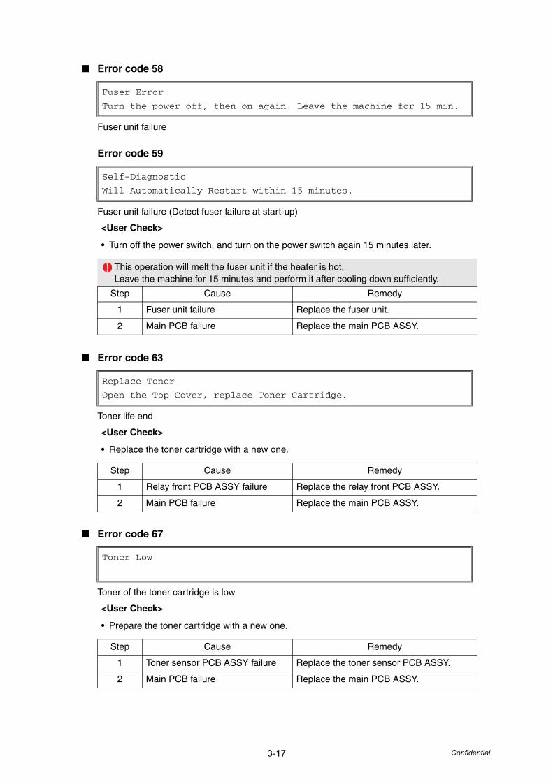
3-17 Confidential
■ Error code 58
Fuser unit failure
Error code 59
Fuser unit failure (Detect fuser failure at start-up)
■ Error code 63
Toner life end
■ Error code 67
Toner of the toner cartridge is low
Fuser Error
Turn the power off, then on again. Leave the machine for 15 min.
Self-Diagnostic
Will Automatically Restart within 15 minutes.
<User Check>
• Turn off the power switch, and turn on the power switch again 15 minutes later.
This operation will melt the fuser unit if the heater is hot. Leave the machine for 15 minutes and perform it after cooling down sufficiently.
Step Cause Remedy
1 Fuser unit failure Replace the fuser unit.
2 Main PCB failure Replace the main PCB ASSY.
Replace Toner
Open the Top Cover, replace Toner Cartridge.
<User Check>
• Replace the toner cartridge with a new one.
Step Cause Remedy
1 Relay front PCB ASSY failure Replace the relay front PCB ASSY.
2 Main PCB failure Replace the main PCB ASSY.
Toner Low
<User Check>
• Prepare the toner cartridge with a new one.
Step Cause Remedy
1 Toner sensor PCB ASSY failure Replace the toner sensor PCB ASSY.
2 Main PCB failure Replace the main PCB ASSY.
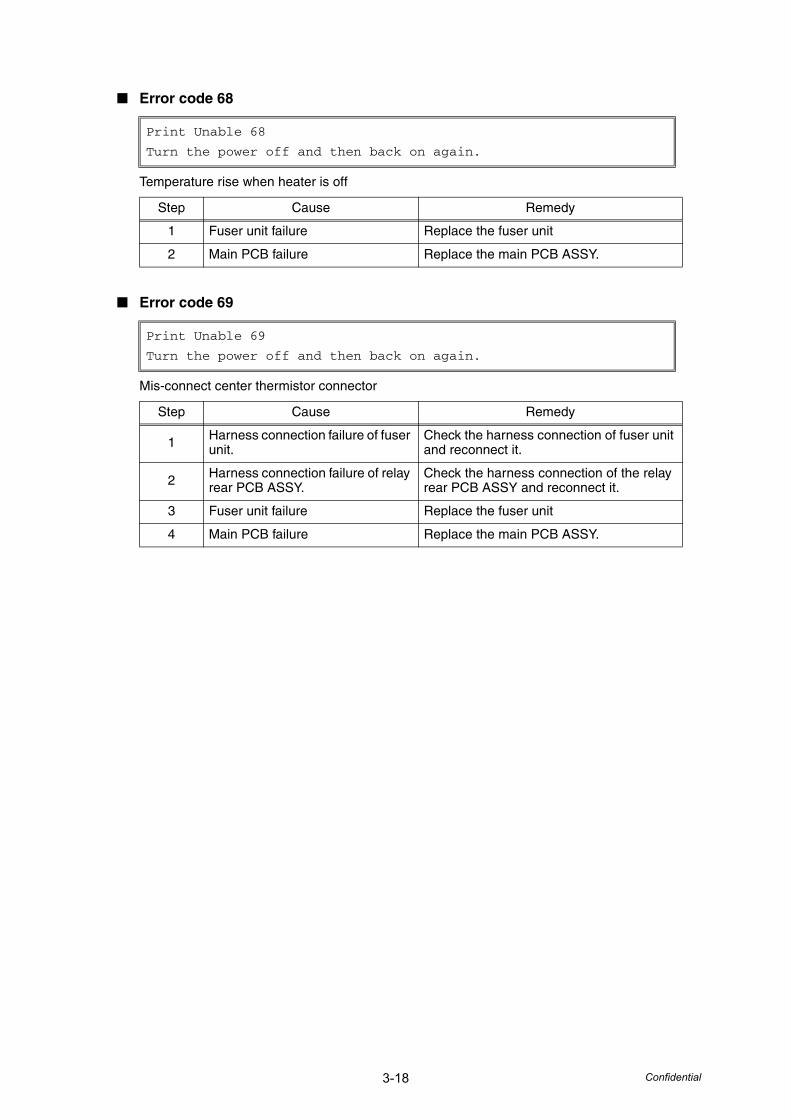
3-18 Confidential
■ Error code 68
Temperature rise when heater is off
■ Error code 69
Mis-connect center thermistor connector
Print Unable 68
Turn the power off and then back on again.
Step Cause Remedy
1 Fuser unit failure Replace the fuser unit
2 Main PCB failure Replace the main PCB ASSY.
Print Unable 69
Turn the power off and then back on again.
Step Cause Remedy
1 Harness connection failure of fuser unit.
Check the harness connection of fuser unit and reconnect it.
2 Harness connection failure of relay rear PCB ASSY.
Check the harness connection of the relay rear PCB ASSY and reconnect it.
3 Fuser unit failure Replace the fuser unit
4 Main PCB failure Replace the main PCB ASSY.
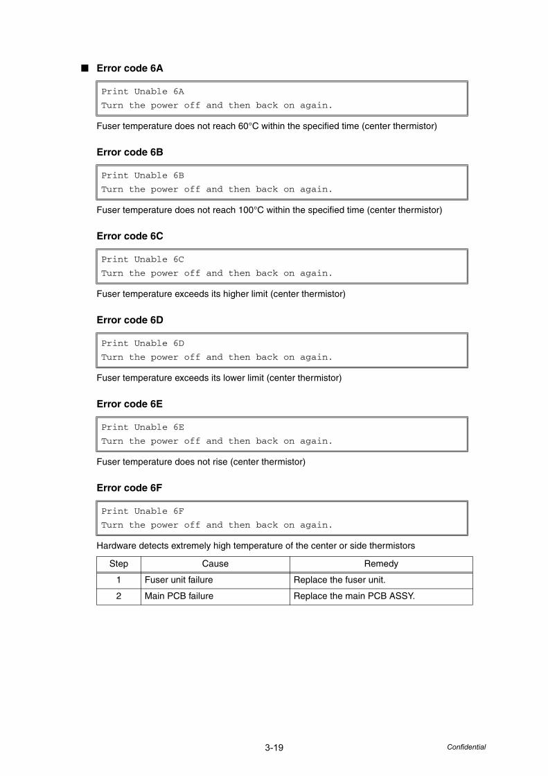
3-19 Confidential
■ Error code 6A
Fuser temperature does not reach 60°C within the specified time (center thermistor)
Error code 6B
Fuser temperature does not reach 100°C within the specified time (center thermistor)
Error code 6C
Fuser temperature exceeds its higher limit (center thermistor)
Error code 6D
Fuser temperature exceeds its lower limit (center thermistor)
Error code 6E
Fuser temperature does not rise (center thermistor)
Error code 6F
Hardware detects extremely high temperature of the center or side thermistors
Print Unable 6A
Turn the power off and then back on again.
Print Unable 6B
Turn the power off and then back on again.
Print Unable 6C
Turn the power off and then back on again.
Print Unable 6D
Turn the power off and then back on again.
Print Unable 6E
Turn the power off and then back on again.
Print Unable 6F
Turn the power off and then back on again.
Step Cause Remedy
1 Fuser unit failure Replace the fuser unit.
2 Main PCB failure Replace the main PCB ASSY.
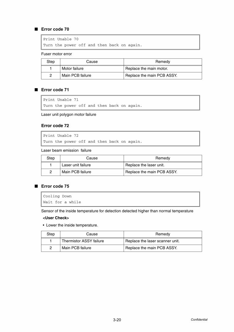
3-20 Confidential
■ Error code 70
Fuser motor error
■ Error code 71
Laser unit polygon motor failure
Error code 72
Laser beam emission failure
■ Error code 75
Sensor of the inside temperature for detection detected higher than normal temperature
Print Unable 70
Turn the power off and then back on again.
Step Cause Remedy
1 Motor failure Replace the main motor.
2 Main PCB failure Replace the main PCB ASSY.
Print Unable 71
Turn the power off and then back on again.
Print Unable 72
Turn the power off and then back on again.
Step Cause Remedy
1 Laser unit failure Replace the laser unit.
2 Main PCB failure Replace the main PCB ASSY.
Cooling Down
Wait for a while
<User Check>
• Lower the inside temperature.
Step Cause Remedy
1 Thermistor ASSY failure Replace the laser scanner unit.
2 Main PCB failure Replace the main PCB ASSY.
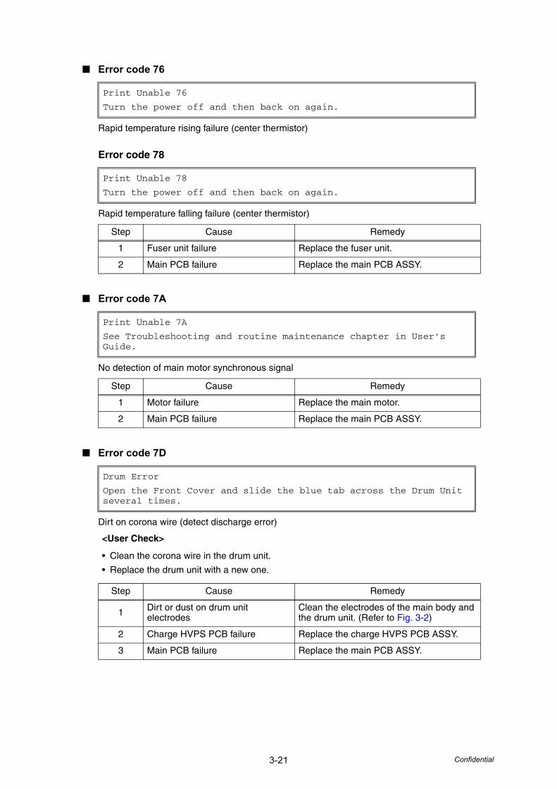
3-21 Confidential
■ Error code 76
Rapid temperature rising failure (center thermistor)
Error code 78
Rapid temperature falling failure (center thermistor)
■ Error code 7A
No detection of main motor synchronous signal
■ Error code 7D
Dirt on corona wire (detect discharge error)
Print Unable 76
Turn the power off and then back on again.
Print Unable 78
Turn the power off and then back on again.
Step Cause Remedy
1 Fuser unit failure Replace the fuser unit.
2 Main PCB failure Replace the main PCB ASSY.
Print Unable 7A
See Troubleshooting and routine maintenance chapter in User's Guide.
Step Cause Remedy
1 Motor failure Replace the main motor.
2 Main PCB failure Replace the main PCB ASSY.
Drum Error
Open the Front Cover and slide the blue tab across the Drum Unit several times.
<User Check>
• Clean the corona wire in the drum unit.
• Replace the drum unit with a new one.
Step Cause Remedy
1 Dirt or dust on drum unit electrodes
Clean the electrodes of the main body and the drum unit. (Refer to Fig. 3-2)
2 Charge HVPS PCB failure Replace the charge HVPS PCB ASSY.
3 Main PCB failure Replace the main PCB ASSY.
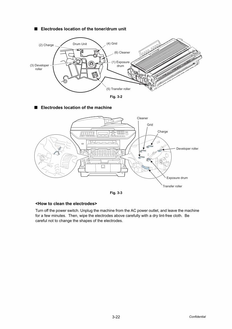
3-22 Confidential
■ Electrodes location of the toner/drum unit
Fig. 3-2
■ Electrodes location of the machine
Fig. 3-3
<How to clean the electrodes>Turn off the power switch. Unplug the machine from the AC power outlet, and leave the machine for a few minutes. Then, wipe the electrodes above carefully with a dry lint-free cloth. Be careful not to change the shapes of the electrodes.
Drum Unit (4) Grid
(6) Cleaner
(2) Charge
(3) Developer roller
(5) Transfer roller
(1) Exposure drum
Developer roller
Charge
Grid
Cleaner
Transfer roller
Exposure drum
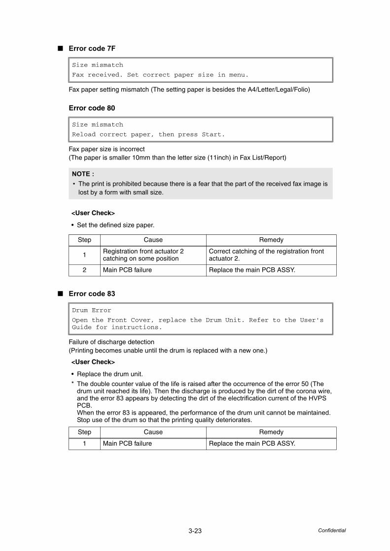
3-23 Confidential
■ Error code 7F
Fax paper setting mismatch (The setting paper is besides the A4/Letter/Legal/Folio)
Error code 80
Fax paper size is incorrect (The paper is smaller 10mm than the letter size (11inch) in Fax List/Report)
■ Error code 83
Failure of discharge detection(Printing becomes unable until the drum is replaced with a new one.)
Size mismatch
Fax received. Set correct paper size in menu.
Size mismatch
Reload correct paper, then press Start.
NOTE :• The print is prohibited because there is a fear that the part of the received fax image is
lost by a form with small size.
<User Check>
• Set the defined size paper.
Step Cause Remedy
1 Registration front actuator 2 catching on some position
Correct catching of the registration front actuator 2.
2 Main PCB failure Replace the main PCB ASSY.
Drum Error
Open the Front Cover, replace the Drum Unit. Refer to the User's Guide for instructions.
<User Check>
• Replace the drum unit.
* The double counter value of the life is raised after the occurrence of the error 50 (The drum unit reached its life). Then the discharge is produced by the dirt of the corona wire, and the error 83 appears by detecting the dirt of the electrification current of the HVPS PCB.When the error 83 is appeared, the performance of the drum unit cannot be maintained. Stop use of the drum so that the printing quality deteriorates.
Step Cause Remedy
1 Main PCB failure Replace the main PCB ASSY.
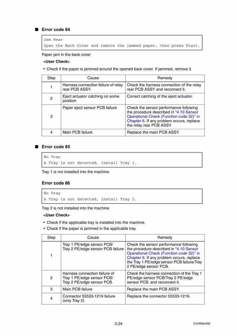
3-24 Confidential
■ Error code 84
Paper jam in the back cover
■ Error code 85
Tray 1 is not installed into the machine
Error code 86
Tray 2 is not installed into the machine
Jam Rear
Open the Back Cover and remove the jammed paper, then press Start.
<User Check>
• Check if the paper is jammed around the opened back cover. If jammed, remove it.
Step Cause Remedy
1 Harness connection failure of relay rear PCB ASSY.
Check the harness connection of the relay rear PCB ASSY and reconnect it.
2 Eject actuator catching on some position
Correct catching of the eject actuator.
3
Paper eject sensor PCB failure Check the sensor performance following the procedure described in "4.10 Sensor Operational Check (Function code 32)" in Chapter 6. If any problem occurs, replace the relay rear PCB ASSY.
4 Main PCB failure Replace the main PCB ASSY.
No Tray
A Tray is not detected, install Tray 1.
No Tray
A Tray is not detected, install Tray 2.
<User Check>
• Check if the applicable tray is installed into the machine.
• Check if the paper is jammed in the applicable tray.
Step Cause Remedy
1
Tray 1 PE/edge sensor PCB/Tray 2 PE/edge sensor PCB failure
Check the sensor performance following the procedure described in "4.10 Sensor Operational Check (Function code 32)" in Chapter 6. If any problem occurs, replace the Tray 1 PE/edge sensor PCB failure/Tray 2 PE/edge sensor PCB.
2Harness connection failure of Tray 1 PE/edge sensor PCB/Tray 2 PE/edge sensor PCB.
Check the harness connection of the Tray 1 PE/edge sensor PCB/Tray 2 PE/edge sensor PCB. and reconnect it.
3 Main PCB failure Replace the main PCB ASSY.
4 Connector 55533-1219 failure (only Tray 2)
Replace the connector 55533-1219.
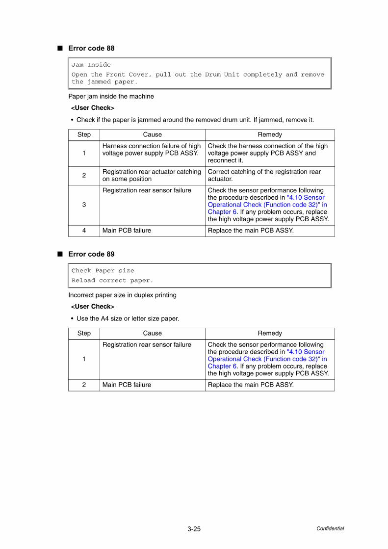
3-25 Confidential
■ Error code 88
Paper jam inside the machine
■ Error code 89
Incorrect paper size in duplex printing
Jam Inside
Open the Front Cover, pull out the Drum Unit completely and remove the jammed paper.
<User Check>
• Check if the paper is jammed around the removed drum unit. If jammed, remove it.
Step Cause Remedy
1Harness connection failure of high voltage power supply PCB ASSY.
Check the harness connection of the high voltage power supply PCB ASSY and reconnect it.
2 Registration rear actuator catching on some position
Correct catching of the registration rear actuator.
3
Registration rear sensor failure Check the sensor performance following the procedure described in "4.10 Sensor Operational Check (Function code 32)" in Chapter 6. If any problem occurs, replace the high voltage power supply PCB ASSY.
4 Main PCB failure Replace the main PCB ASSY.
Check Paper size
Reload correct paper.
<User Check>
• Use the A4 size or letter size paper.
Step Cause Remedy
1
Registration rear sensor failure Check the sensor performance following the procedure described in "4.10 Sensor Operational Check (Function code 32)" in Chapter 6. If any problem occurs, replace the high voltage power supply PCB ASSY.
2 Main PCB failure Replace the main PCB ASSY.
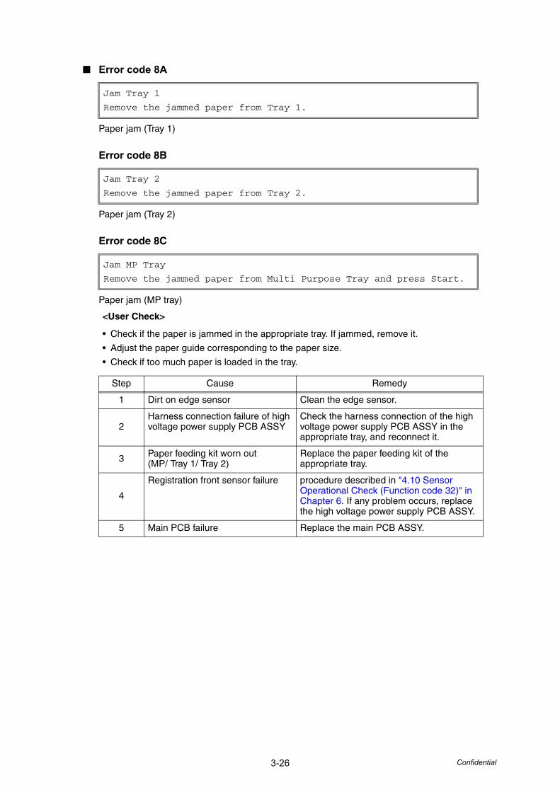
3-26 Confidential
■ Error code 8A
Paper jam (Tray 1)
Error code 8B
Paper jam (Tray 2)
Error code 8C
Paper jam (MP tray)
Jam Tray 1
Remove the jammed paper from Tray 1.
Jam Tray 2
Remove the jammed paper from Tray 2.
Jam MP Tray
Remove the jammed paper from Multi Purpose Tray and press Start.
<User Check>
• Check if the paper is jammed in the appropriate tray. If jammed, remove it.
• Adjust the paper guide corresponding to the paper size.
• Check if too much paper is loaded in the tray.
Step Cause Remedy
1 Dirt on edge sensor Clean the edge sensor.
2Harness connection failure of high voltage power supply PCB ASSY
Check the harness connection of the high voltage power supply PCB ASSY in the appropriate tray, and reconnect it.
3 Paper feeding kit worn out(MP/ Tray 1/ Tray 2)
Replace the paper feeding kit of the appropriate tray.
4
Registration front sensor failure procedure described in "4.10 Sensor Operational Check (Function code 32)" in Chapter 6. If any problem occurs, replace the high voltage power supply PCB ASSY.
5 Main PCB failure Replace the main PCB ASSY.
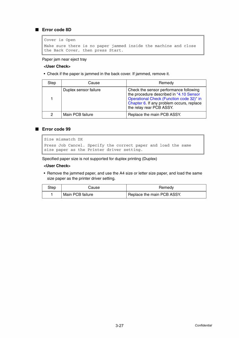
3-27 Confidential
■ Error code 8D
Paper jam near eject tray
■ Error code 99
Specified paper size is not supported for duplex printing (Duplex)
Cover is Open
Make sure there is no paper jammed inside the machine and close the Back Cover, then press Start.
<User Check>
• Check if the paper is jammed in the back cover. If jammed, remove it.
Step Cause Remedy
1
Duplex sensor failure Check the sensor performance following the procedure described in "4.10 Sensor Operational Check (Function code 32)" in Chapter 6. If any problem occurs, replace the relay rear PCB ASSY.
2 Main PCB failure Replace the main PCB ASSY.
Size mismatch DX
Press Job Cancel. Specify the correct paper and load the same size paper as the Printer driver setting.
<User Check>
• Remove the jammed paper, and use the A4 size or letter size paper, and load the same size paper as the printer driver setting.
Step Cause Remedy
1 Main PCB failure Replace the main PCB ASSY.
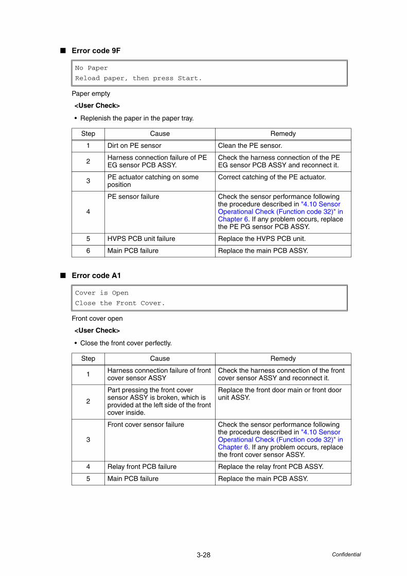
3-28 Confidential
■ Error code 9F
Paper empty
■ Error code A1
Front cover open
No Paper
Reload paper, then press Start.
<User Check>
• Replenish the paper in the paper tray.
Step Cause Remedy
1 Dirt on PE sensor Clean the PE sensor.
2 Harness connection failure of PE EG sensor PCB ASSY.
Check the harness connection of the PE EG sensor PCB ASSY and reconnect it.
3 PE actuator catching on some position
Correct catching of the PE actuator.
4
PE sensor failure Check the sensor performance following the procedure described in "4.10 Sensor Operational Check (Function code 32)" in Chapter 6. If any problem occurs, replace the PE PG sensor PCB ASSY.
5 HVPS PCB unit failure Replace the HVPS PCB unit.
6 Main PCB failure Replace the main PCB ASSY.
Cover is Open
Close the Front Cover.
<User Check>
• Close the front cover perfectly.
Step Cause Remedy
1 Harness connection failure of front cover sensor ASSY
Check the harness connection of the front cover sensor ASSY and reconnect it.
2
Part pressing the front cover sensor ASSY is broken, which is provided at the left side of the front cover inside.
Replace the front door main or front door unit ASSY.
3
Front cover sensor failure Check the sensor performance following the procedure described in "4.10 Sensor Operational Check (Function code 32)" in Chapter 6. If any problem occurs, replace the front cover sensor ASSY.
4 Relay front PCB failure Replace the relay front PCB ASSY.
5 Main PCB failure Replace the main PCB ASSY.
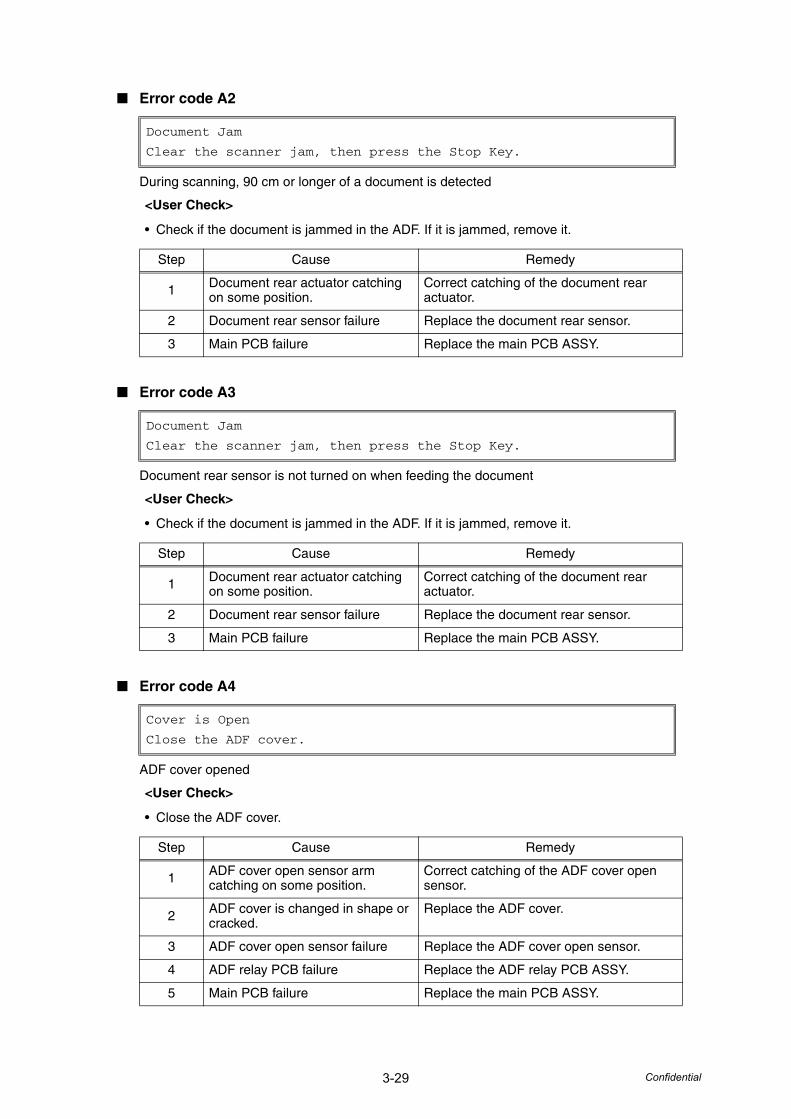
3-29 Confidential
■ Error code A2
During scanning, 90 cm or longer of a document is detected
■ Error code A3
Document rear sensor is not turned on when feeding the document
■ Error code A4
ADF cover opened
Document Jam
Clear the scanner jam, then press the Stop Key.
<User Check>
• Check if the document is jammed in the ADF. If it is jammed, remove it.
Step Cause Remedy
1 Document rear actuator catching on some position.
Correct catching of the document rear actuator.
2 Document rear sensor failure Replace the document rear sensor.
3 Main PCB failure Replace the main PCB ASSY.
Cover is Open
Close the ADF cover.
<User Check>
• Close the ADF cover.
Step Cause Remedy
1 ADF cover open sensor arm catching on some position.
Correct catching of the ADF cover open sensor.
2 ADF cover is changed in shape or cracked.
Replace the ADF cover.
3 ADF cover open sensor failure Replace the ADF cover open sensor.
4 ADF relay PCB failure Replace the ADF relay PCB ASSY.
5 Main PCB failure Replace the main PCB ASSY.
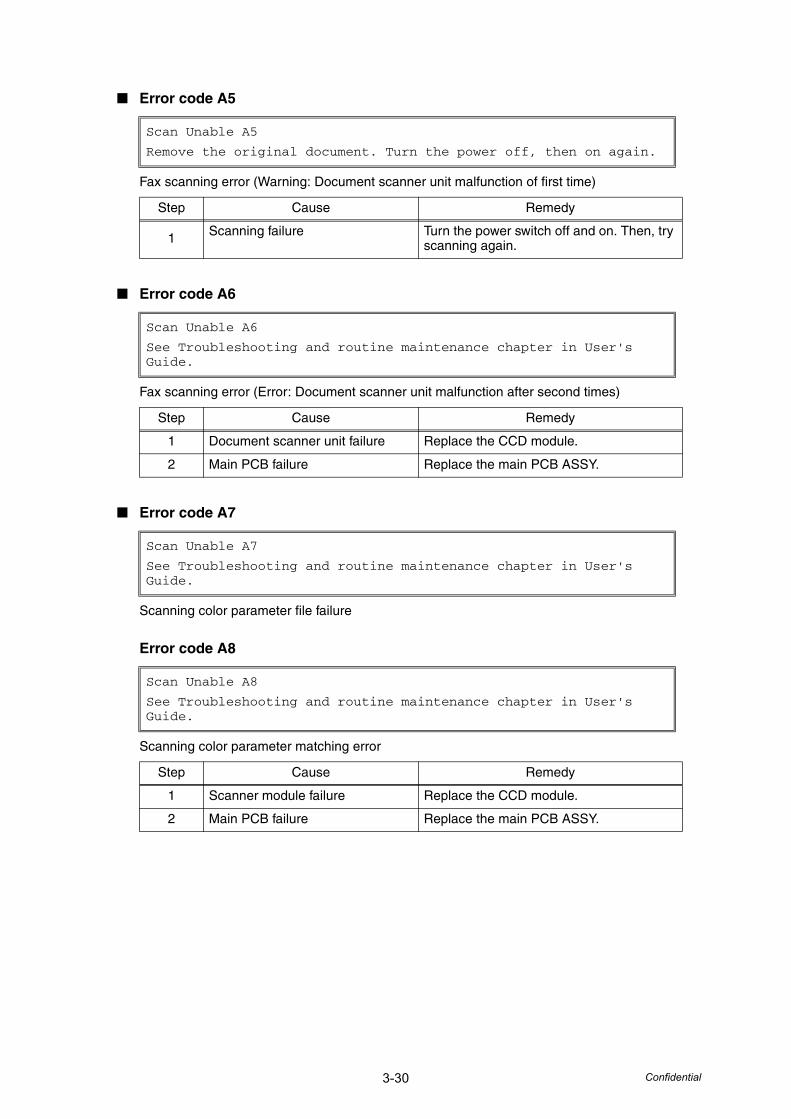
3-30 Confidential
■ Error code A5
Fax scanning error (Warning: Document scanner unit malfunction of first time)
■ Error code A6
Fax scanning error (Error: Document scanner unit malfunction after second times)
■ Error code A7
Scanning color parameter file failure
Error code A8
Scanning color parameter matching error
Scan Unable A5
Remove the original document. Turn the power off, then on again.
Step Cause Remedy
1 Scanning failure Turn the power switch off and on. Then, try scanning again.
Scan Unable A6
See Troubleshooting and routine maintenance chapter in User's Guide.
Step Cause Remedy
1 Document scanner unit failure Replace the CCD module.
2 Main PCB failure Replace the main PCB ASSY.
Scan Unable A7
See Troubleshooting and routine maintenance chapter in User's Guide.
Scan Unable A8
See Troubleshooting and routine maintenance chapter in User's Guide.
Step Cause Remedy
1 Scanner module failure Replace the CCD module.
2 Main PCB failure Replace the main PCB ASSY.
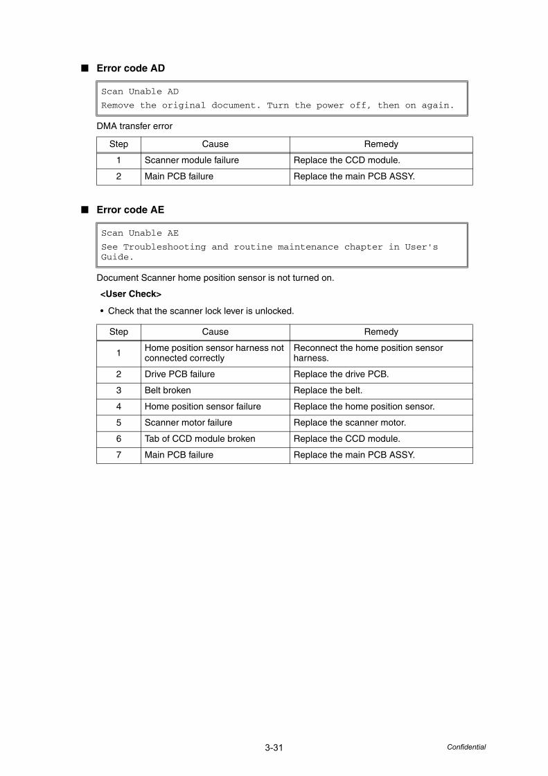
3-31 Confidential
■ Error code AD
DMA transfer error
■ Error code AE
Document Scanner home position sensor is not turned on.
Scan Unable AD
Remove the original document. Turn the power off, then on again.
Step Cause Remedy
1 Scanner module failure Replace the CCD module.
2 Main PCB failure Replace the main PCB ASSY.
Scan Unable AE
See Troubleshooting and routine maintenance chapter in User's Guide.
<User Check>
• Check that the scanner lock lever is unlocked.
Step Cause Remedy
1 Home position sensor harness not connected correctly
Reconnect the home position sensor harness.
2 Drive PCB failure Replace the drive PCB.
3 Belt broken Replace the belt.
4 Home position sensor failure Replace the home position sensor.
5 Scanner motor failure Replace the scanner motor.
6 Tab of CCD module broken Replace the CCD module.
7 Main PCB failure Replace the main PCB ASSY.
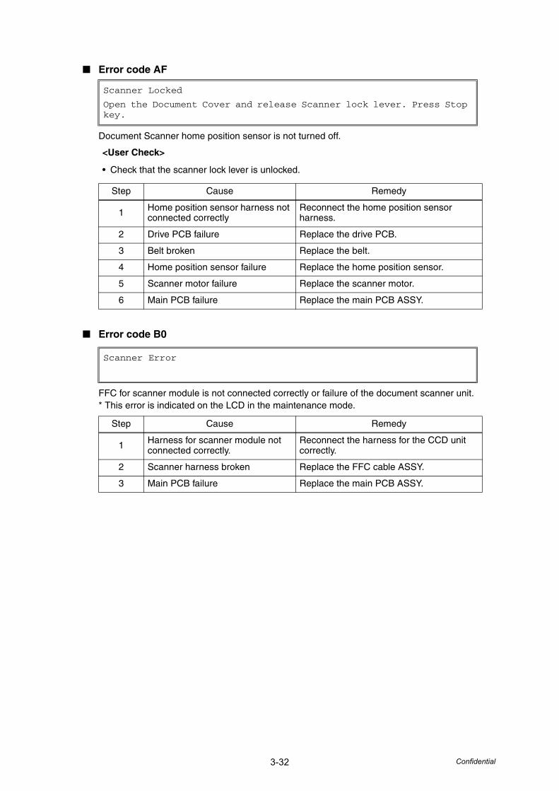
3-32 Confidential
■ Error code AF
Document Scanner home position sensor is not turned off.
■ Error code B0
FFC for scanner module is not connected correctly or failure of the document scanner unit.* This error is indicated on the LCD in the maintenance mode.
Scanner Locked
Open the Document Cover and release Scanner lock lever. Press Stop key.
<User Check>
• Check that the scanner lock lever is unlocked.
Step Cause Remedy
1 Home position sensor harness not connected correctly
Reconnect the home position sensor harness.
2 Drive PCB failure Replace the drive PCB.
3 Belt broken Replace the belt.
4 Home position sensor failure Replace the home position sensor.
5 Scanner motor failure Replace the scanner motor.
6 Main PCB failure Replace the main PCB ASSY.
Scanner Error
Step Cause Remedy
1 Harness for scanner module not connected correctly.
Reconnect the harness for the CCD unit correctly.
2 Scanner harness broken Replace the FFC cable ASSY.
3 Main PCB failure Replace the main PCB ASSY.
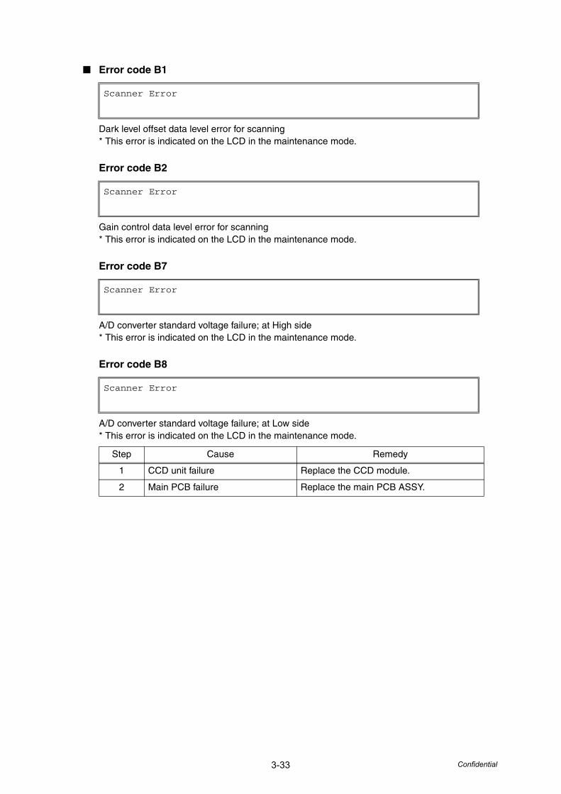
3-33 Confidential
■ Error code B1
Dark level offset data level error for scanning* This error is indicated on the LCD in the maintenance mode.
Error code B2
Gain control data level error for scanning* This error is indicated on the LCD in the maintenance mode.
Error code B7
A/D converter standard voltage failure; at High side* This error is indicated on the LCD in the maintenance mode.
Error code B8
A/D converter standard voltage failure; at Low side* This error is indicated on the LCD in the maintenance mode.
Scanner Error
Scanner Error
Scanner Error
Scanner Error
Step Cause Remedy
1 CCD unit failure Replace the CCD module.
2 Main PCB failure Replace the main PCB ASSY.
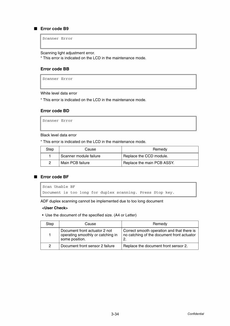
3-34 Confidential
■ Error code B9
Scanning light adjustment error.* This error is indicated on the LCD in the maintenance mode.
Error code BB
White level data error
* This error is indicated on the LCD in the maintenance mode.
Error code BD
Black level data error
* This error is indicated on the LCD in the maintenance mode.
■ Error code BF
ADF duplex scanning cannot be implemented due to too long document
Scanner Error
Scanner Error
Scanner Error
Step Cause Remedy
1 Scanner module failure Replace the CCD module.
2 Main PCB failure Replace the main PCB ASSY.
Scan Unable BF
Document is too long for duplex scanning. Press Stop key.
<User Check>
• Use the document of the specified size. (A4 or Letter)
Step Cause Remedy
1Document front actuator 2 not operating smoothly or catching in some position.
Correct smooth operation and that there is no catching of the document front actuator 2.
2 Document front sensor 2 failure Replace the document front sensor 2.
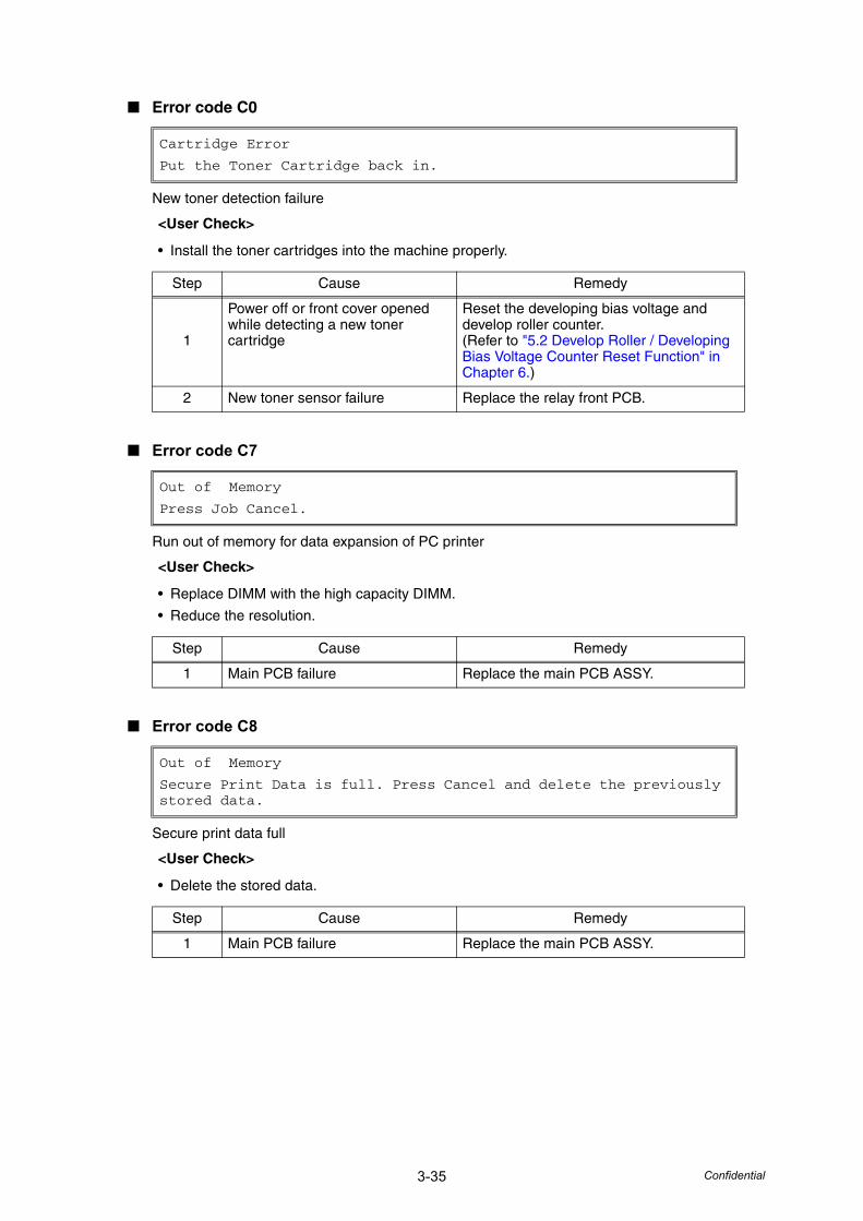
3-35 Confidential
■ Error code C0
New toner detection failure
■ Error code C7
Run out of memory for data expansion of PC printer
■ Error code C8
Secure print data full
Cartridge Error
Put the Toner Cartridge back in.
<User Check>
• Install the toner cartridges into the machine properly.
Step Cause Remedy
1
Power off or front cover opened while detecting a new toner cartridge
Reset the developing bias voltage and develop roller counter.(Refer to "5.2 Develop Roller / Developing Bias Voltage Counter Reset Function" in Chapter 6.)
2 New toner sensor failure Replace the relay front PCB.
Out of Memory
Press Job Cancel.
<User Check>
• Replace DIMM with the high capacity DIMM.
• Reduce the resolution.
Step Cause Remedy
1 Main PCB failure Replace the main PCB ASSY.
Out of Memory
Secure Print Data is full. Press Cancel and delete the previously stored data.
<User Check>
• Delete the stored data.
Step Cause Remedy
1 Main PCB failure Replace the main PCB ASSY.
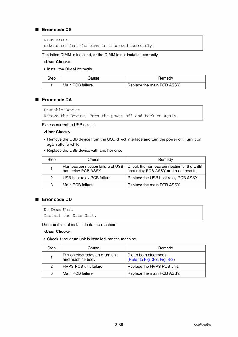
3-36 Confidential
■ Error code C9
The failed DIMM is installed, or the DIMM is not installed correctly.
■ Error code CA
Excess current to USB device
■ Error code CD
Drum unit is not installed into the machine
DIMM Error
Make sure that the DIMM is inserted correctly.
<User Check>
• Install the DIMM correctly.
Step Cause Remedy
1 Main PCB failure Replace the main PCB ASSY.
Unusable Device
Remove the Device. Turn the power off and back on again.
<User Check>
• Remove the USB device from the USB direct interface and turn the power off. Turn it on again after a while.
• Replace the USB device with another one.
Step Cause Remedy
1 Harness connection failure of USB host relay PCB ASSY
Check the harness connection of the USB host relay PCB ASSY and reconnect it.
2 USB host relay PCB failure Replace the USB host relay PCB ASSY.
3 Main PCB failure Replace the main PCB ASSY.
No Drum Unit
Install the Drum Unit.
<User Check>
• Check if the drum unit is installed into the machine.
Step Cause Remedy
1 Dirt on electrodes on drum unit and machine body
Clean both electrodes.(Refer to Fig. 3-2, Fig. 3-3)
2 HVPS PCB unit failure Replace the HVPS PCB unit.
3 Main PCB failure Replace the main PCB ASSY.
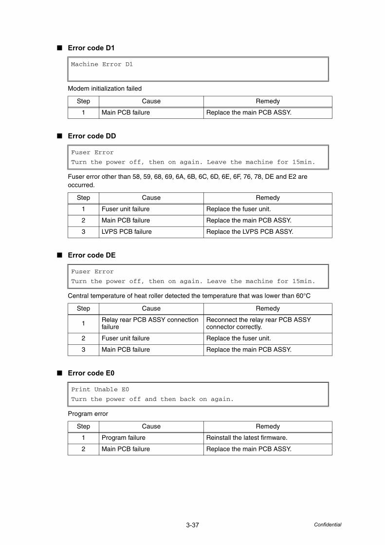
3-37 Confidential
■ Error code D1
Modem initialization failed
■ Error code DD
Fuser error other than 58, 59, 68, 69, 6A, 6B, 6C, 6D, 6E, 6F, 76, 78, DE and E2 are occurred.
■ Error code DE
Central temperature of heat roller detected the temperature that was lower than 60°C
■ Error code E0
Program error
Machine Error D1
Step Cause Remedy
1 Main PCB failure Replace the main PCB ASSY.
Fuser Error
Turn the power off, then on again. Leave the machine for 15min.
Step Cause Remedy
1 Fuser unit failure Replace the fuser unit.
2 Main PCB failure Replace the main PCB ASSY.
3 LVPS PCB failure Replace the LVPS PCB ASSY.
Fuser Error
Turn the power off, then on again. Leave the machine for 15min.
Step Cause Remedy
1 Relay rear PCB ASSY connection failure
Reconnect the relay rear PCB ASSY connector correctly.
2 Fuser unit failure Replace the fuser unit.
3 Main PCB failure Replace the main PCB ASSY.
Print Unable E0
Turn the power off and then back on again.
Step Cause Remedy
1 Program failure Reinstall the latest firmware.
2 Main PCB failure Replace the main PCB ASSY.
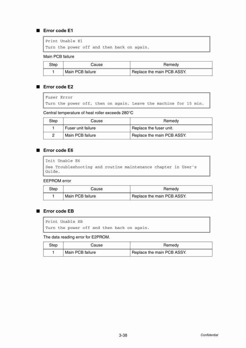
3-38 Confidential
■ Error code E1
Main PCB failure
■ Error code E2
Central temperature of heat roller exceeds 280°C
■ Error code E6
EEPROM error
■ Error code EB
The data reading error for E2PROM.
Print Unable E1
Turn the power off and then back on again.
Step Cause Remedy
1 Main PCB failure Replace the main PCB ASSY.
Fuser Error
Turn the power off, then on again. Leave the machine for 15 min.
Step Cause Remedy
1 Fuser unit failure Replace the fuser unit.
2 Main PCB failure Replace the main PCB ASSY.
Init Unable E6
See Troubleshooting and routine maintenance chapter in User's Guide.
Step Cause Remedy
1 Main PCB failure Replace the main PCB ASSY.
Print Unable EB
Turn the power off and then back on again.
Step Cause Remedy
1 Main PCB failure Replace the main PCB ASSY.
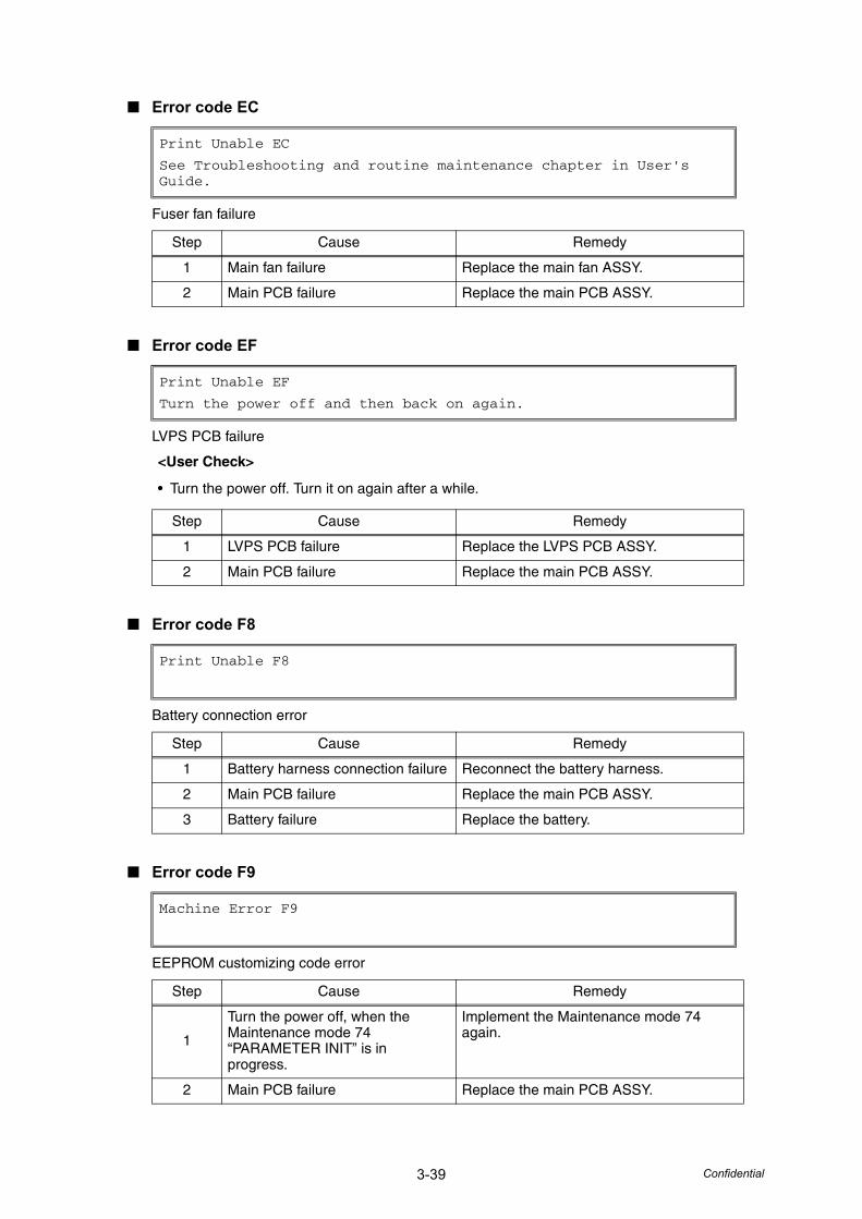
3-39 Confidential
■ Error code EC
Fuser fan failure
■ Error code EF
LVPS PCB failure
■ Error code F8
Battery connection error
■ Error code F9
EEPROM customizing code error
Print Unable EC
See Troubleshooting and routine maintenance chapter in User's Guide.
Step Cause Remedy
1 Main fan failure Replace the main fan ASSY.
2 Main PCB failure Replace the main PCB ASSY.
Print Unable EF
Turn the power off and then back on again.
<User Check>
• Turn the power off. Turn it on again after a while.
Step Cause Remedy
1 LVPS PCB failure Replace the LVPS PCB ASSY.
2 Main PCB failure Replace the main PCB ASSY.
Print Unable F8
Step Cause Remedy
1 Battery harness connection failure Reconnect the battery harness.
2 Main PCB failure Replace the main PCB ASSY.
3 Battery failure Replace the battery.
Machine Error F9
Step Cause Remedy
1
Turn the power off, when the Maintenance mode 74 “PARAMETER INIT” is in progress.
Implement the Maintenance mode 74 again.
2 Main PCB failure Replace the main PCB ASSY.

3-40 Confidential
■ Error code FF
Excess current to USB HOST PCB ASSY error
Unusable Device
Remove the Device. Turn the power off and back on again.
Step Cause Remedy
1 USB HOST PCB failure Replace the USB HOST PCB ASSY.
2 Main PCB failure Replace the main PCB ASSY.
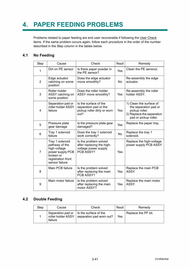
3-41 Confidential
4. PAPER FEEDING PROBLEMS
Problems related to paper feeding are end user recoverable if following the User Check items. If the same problem occurs again, follow each procedure in the order of the number described in the Step column in the tables below.
4.1 No Feeding
4.2 Double Feeding
Step Cause Check Result Remedy
1 Dirt on PE sensor Is there paper powder in the PE sensor? Yes Clean the PE sensnor.
2Edge actuator catching on some position
Does the edge actuator move smoothly? No
Re-assembly the edge actuator.
3Roller holder ASSY catching on some position
Does the roller holder ASSY move smoothly? Yes
Re-assembly the roller holder ASSY.
4
Separation pad or roller holder ASSY failure
Is the surface of the separation pad or the pickup roller dirty or worn out?
Yes
1) Clean the surface of the separation pad or pickup roller.
2) Replace the separation pad or pickup roller.
5 Pressure plate gear damage
Is the pressure plate gear damaged? Yes Replace the paper tray.
6 Tray 1 solenoid failure
Does the tray 1 solenoid work correctly? No Replace the tray 1
solenoid.
7
Tray 1 solenoid pathway of the high-voltage power supply PCB broken or registration front sensor failure
Is the problem solved after replacing the high-voltage power supply PCB ASSY? Yes
Replace the high-voltage power supply PCB ASSY.
8Main PCB failure Is the problem solved
after replacing the main PCB ASSY?
YesReplace the main PCB ASSY.
9Main motor failure Is the problem solved
after replacing the main motor ASSY?
YesReplace the main motor ASSY.
Step Cause Check Result Remedy
1Separation pad or roller holder ASSY failure
Is the surface of the separation pad worn out? Yes
Replace the PF kit.
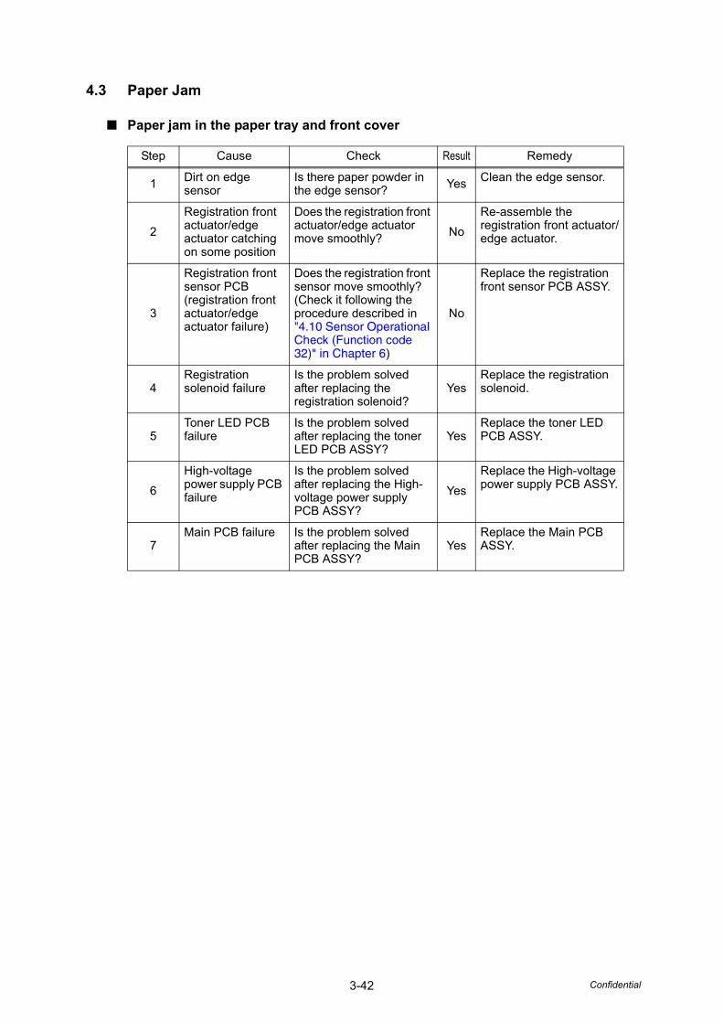
3-42 Confidential
4.3 Paper Jam
■ Paper jam in the paper tray and front cover
Step Cause Check Result Remedy
1 Dirt on edge sensor
Is there paper powder in the edge sensor? Yes Clean the edge sensor.
2Registration front actuator/edge actuator catching on some position
Does the registration front actuator/edge actuator move smoothly? No
Re-assemble the registration front actuator/edge actuator.
3
Registration front sensor PCB (registration front actuator/edge actuator failure)
Does the registration front sensor move smoothly? (Check it following the procedure described in "4.10 Sensor Operational Check (Function code 32)" in Chapter 6)
No
Replace the registration front sensor PCB ASSY.
4Registration solenoid failure
Is the problem solved after replacing the registration solenoid?
YesReplace the registration solenoid.
5Toner LED PCB failure
Is the problem solved after replacing the toner LED PCB ASSY?
YesReplace the toner LED PCB ASSY.
6High-voltage power supply PCB failure
Is the problem solved after replacing the High-voltage power supply PCB ASSY?
YesReplace the High-voltage power supply PCB ASSY.
7Main PCB failure Is the problem solved
after replacing the Main PCB ASSY?
YesReplace the Main PCB ASSY.
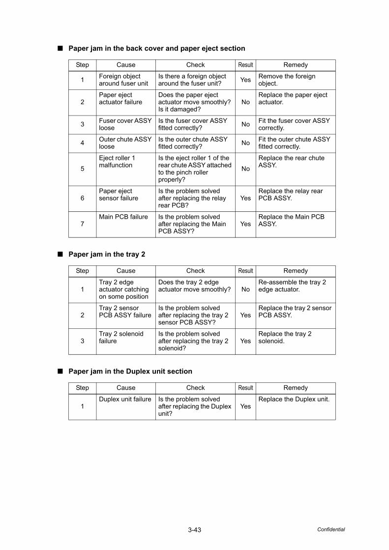
3-43 Confidential
■ Paper jam in the back cover and paper eject section
■ Paper jam in the tray 2
■ Paper jam in the Duplex unit section
Step Cause Check Result Remedy
1 Foreign object around fuser unit
Is there a foreign object around the fuser unit? Yes Remove the foreign
object.
2Paper eject actuator failure
Does the paper eject actuator move smoothly? Is it damaged?
NoReplace the paper eject actuator.
3 Fuser cover ASSY loose
Is the fuser cover ASSY fitted correctly? No Fit the fuser cover ASSY
correctly.
4 Outer chute ASSY loose
Is the outer chute ASSY fitted correctly? No Fit the outer chute ASSY
fitted correctly.
5Eject roller 1 malfunction
Is the eject roller 1 of the rear chute ASSY attached to the pinch roller properly?
NoReplace the rear chute ASSY.
6Paper eject sensor failure
Is the problem solved after replacing the relay rear PCB?
YesReplace the relay rear PCB ASSY.
7Main PCB failure Is the problem solved
after replacing the Main PCB ASSY?
YesReplace the Main PCB ASSY.
Step Cause Check Result Remedy
1Tray 2 edge actuator catching on some position
Does the tray 2 edge actuator move smoothly? No
Re-assemble the tray 2 edge actuator.
2Tray 2 sensor PCB ASSY failure
Is the problem solved after replacing the tray 2 sensor PCB ASSY?
YesReplace the tray 2 sensor PCB ASSY.
3Tray 2 solenoid failure
Is the problem solved after replacing the tray 2 solenoid?
YesReplace the tray 2 solenoid.
Step Cause Check Result Remedy
1Duplex unit failure Is the problem solved
after replacing the Duplex unit?
YesReplace the Duplex unit.
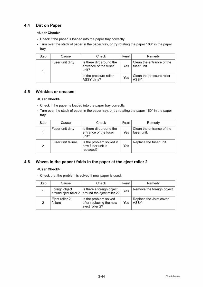
3-44 Confidential
4.4 Dirt on Paper
4.5 Wrinkles or creases
4.6 Waves in the paper / folds in the paper at the eject roller 2
<User Check>
- Check if the paper is loaded into the paper tray correctly.- Turn over the stack of paper in the paper tray, or try rotating the paper 180° in the paper
tray.
Step Cause Check Result Remedy
1
Fuser unit dirty Is there dirt around the entrance of the fuser unit?
YesClean the entrance of the fuser unit.
Is the pressure roller ASSY dirty? Yes Clean the pressure roller
ASSY.
<User Check>
- Check if the paper is loaded into the paper tray correctly.- Turn over the stack of paper in the paper tray, or try rotating the paper 180° in the paper
tray.
Step Cause Check Result Remedy
1Fuser unit dirty Is there dirt around the
entrance of the fuser unit?
YesClean the entrance of the fuser unit.
2Fuser unit failure Is the problem solved if
new fuser unit is replaced?
YesReplace the fuser unit.
<User Check>
- Check that the problem is solved if new paper is used.
Step Cause Check Result Remedy
1 Foreign object around eject roller 2
Is there a foreign object around the eject roller 2? Yes Remove the foreign object.
2Eject roller 2 failure
Is the problem solved after replacing the new eject roller 2?
YesReplace the Joint cover ASSY.
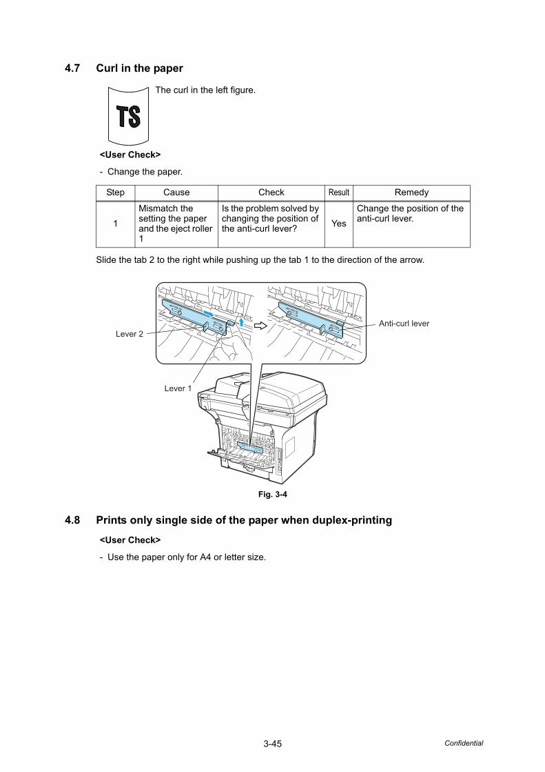
3-45 Confidential
4.7 Curl in the paper
Slide the tab 2 to the right while pushing up the tab 1 to the direction of the arrow.
Fig. 3-4
4.8 Prints only single side of the paper when duplex-printing
The curl in the left figure.
<User Check>
- Change the paper.
Step Cause Check Result Remedy
1Mismatch the setting the paper and the eject roller 1
Is the problem solved by changing the position of the anti-curl lever? Yes
Change the position of the anti-curl lever.
<User Check>
- Use the paper only for A4 or letter size.
Lever 2Anti-curl lever
Lever 1
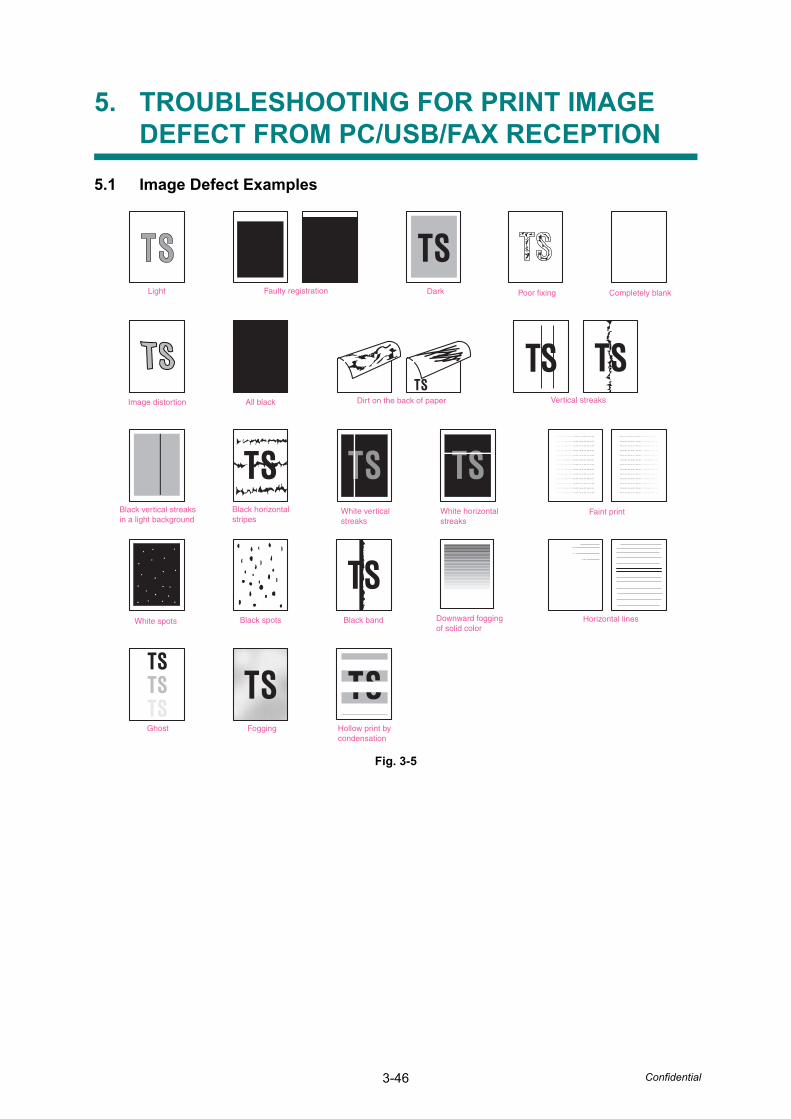
3-46 Confidential
5. TROUBLESHOOTING FOR PRINT IMAGE DEFECT FROM PC/USB/FAX RECEPTION
5.1 Image Defect Examples
Fig. 3-5
Light Poor fixing
Dirt on the back of paper
White verticalstreaks
Faint print
Black spots Downward foggingof solid color
Horizontal lines
Ghost Fogging
Black bandWhite spots
White horizontalstreaks
Vertical streaks
Black vertical streaksin a light background
Black horizontalstripes
Completely blank
Image distortion All black
Faulty registration Dark
Hollow print by condensation
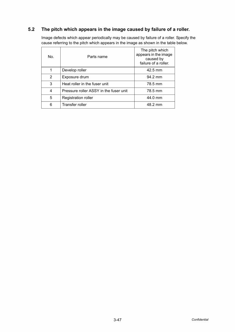
3-47 Confidential
5.2 The pitch which appears in the image caused by failure of a roller.Image defects which appear periodically may be caused by failure of a roller. Specify the cause referring to the pitch which appears in the image as shown in the table below.
No. Parts nameThe pitch which
appears in the image caused by
failure of a roller.
1 Develop roller 42.5 mm
2 Exposure drum 94.2 mm
3 Heat roller in the fuser unit 78.5 mm
4 Pressure roller ASSY in the fuser unit 78.5 mm
5 Registration roller 44.0 mm
6 Transfer roller 48.2 mm
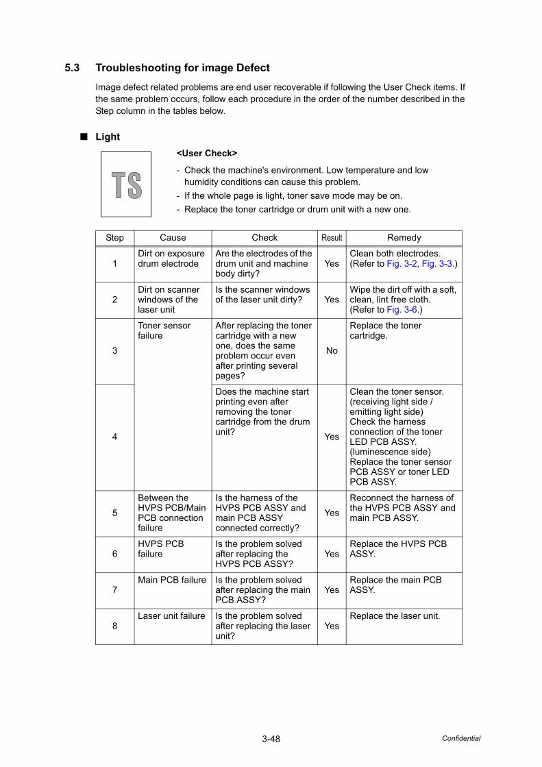
3-48 Confidential
5.3 Troubleshooting for image DefectImage defect related problems are end user recoverable if following the User Check items. If the same problem occurs, follow each procedure in the order of the number described in the Step column in the tables below.
■ Light<User Check>
- Check the machine's environment. Low temperature and low humidity conditions can cause this problem.
- If the whole page is light, toner save mode may be on.- Replace the toner cartridge or drum unit with a new one.
Step Cause Check Result Remedy
1Dirt on exposure drum electrode
Are the electrodes of the drum unit and machine body dirty?
YesClean both electrodes.(Refer to Fig. 3-2, Fig. 3-3.)
2Dirt on scanner windows of the laser unit
Is the scanner windows of the laser unit dirty? Yes
Wipe the dirt off with a soft, clean, lint free cloth.(Refer to Fig. 3-6.)
3
Toner sensor failure
After replacing the toner cartridge with a new one, does the same problem occur even after printing several pages?
No
Replace the toner cartridge.
4
Does the machine start printing even after removing the toner cartridge from the drum unit? Yes
Clean the toner sensor. (receiving light side / emitting light side)Check the harness connection of the toner LED PCB ASSY. (luminescence side)Replace the toner sensor PCB ASSY or toner LED PCB ASSY.
5Between the HVPS PCB/Main PCB connection failure
Is the harness of the HVPS PCB ASSY and main PCB ASSY connected correctly?
YesReconnect the harness of the HVPS PCB ASSY and main PCB ASSY.
6HVPS PCB failure
Is the problem solved after replacing the HVPS PCB ASSY?
YesReplace the HVPS PCB ASSY.
7Main PCB failure Is the problem solved
after replacing the main PCB ASSY?
YesReplace the main PCB ASSY.
8Laser unit failure Is the problem solved
after replacing the laser unit?
YesReplace the laser unit.
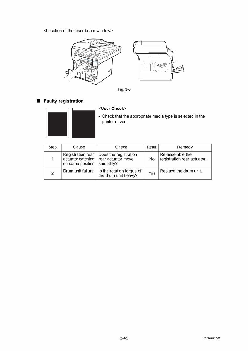
3-49 Confidential
<Location of the leser beam window>
Fig. 3-6
■ Faulty registration<User Check>
- Check that the appropriate media type is selected in the printer driver.
Step Cause Check Result Remedy
1Registration rear actuator catching on some position
Does the registration rear actuator move smoothly?
NoRe-assemble the registration rear actuator.
2 Drum unit failure Is the rotation torque of the drum unit heavy? Yes Replace the drum unit.
3-50 Confidential
■ Dark<User Check>
- Check the machine's environment. High temperature and high humidity conditions can cause this problem.
- Replace the drum unit with a new one.- Replace the toner cartridge with a new one.
Step Cause Check Result Remedy
1 Drum unit electrode dirty
Is the electrode of the drum unit dirty? Yes Clean the electrode.
2Drum unit failure Is the problem solved
after replacing the drum unit?
YesReplace the drum unit.
3Developing bias malfunciton
Is the problem solved after reseting the developer roller counter?
YesReset the developer roller counter.
4HVPS PCB failure
Is the problem solved after replacing the HVPS PCB ASSY?
YesReplace the HVPS PCB ASSY.
5Main PCB failure Is the problem solved
after replacing the main PCB ASSY?
YesReplace the main PCB ASSY.
3-51 Confidential
■ Poor fixing<User Check>
- Replace the drum unit with a new one.- Replace the toner cartridge with a new one.
Step Cause Check Result Remedy
1Low pressure of pressure roller in the fuser unit
Is the problem solved by changing the position of the anti-curl lever?
YesChange the position of the anti-curl lever.
2Fuser unit failure Is the problem solved
after replacing the fuser unit?
YesReplace the fuser unit.
3
Toner sensor failure
Is the "Toner life End" message indicated on the LCD after replacing the current toner cartridge with an empty one?
No
Replace the toner sensor.
4HVPS PCB failure
Is the problem solved after replacing the HVPS PCB ASSY?
YesReplace the HVPS PCB ASSY.
5Main PCB failure Is the problem solved
after replacing the main PCB ASSY?
YesReplace the main PCB ASSY.
6Low-voltage power supply PCB failure
Is the problem solved after replacing the LVPS PCB unit?
YesReplace the LVPS PCB unit.
3-52 Confidential
■ Completely blank
■ Image distortion
<User Check>
- Replace the drum unit with a new one.- Replace the toner cartridge with a new one.
Step Cause Check Result Remedy
1Developing bias voltage conduction failure
Are the electrodes on the drum unit and machine body dirty? Yes
Clean both electrodes.(Refer to Fig. 3-2, Fig. 3-3.)
2Scanner harness of the laser unit connection failure
Is the scanner harness of the laser unit connected securely? No
Reconnect the scanner harness of the laser unit.
3Laser unit failure Is the problem solved
after replacing the laser unit?
YesReplace the laser unit.
4HVPS PCB failure
Is the problem solved after replacing the HVPS PCB ASSY?
YesReplace the HVPS PCB ASSY.
5Main PCB failure Is the problem solved
after replacing the main PCB ASSY?
YesReplace the main PCB ASSY.
Step Cause Check Result Remedy
1
Laser unit not assembled correctly
Is the laser unit assembled into the machine securely? (Check if there is no gap.)
No
Assemble the laser unit correctly and secure the screw.
2
Incorrect radiation angle of scanner diode of laser unit.Scanner motor rotation failure
Is the problem solved after replacing the laser unit? Yes
Replace the laser unit.
3Main PCB failure Is the problem solved
after replacing the main PCB ASSY?
YesReplace the main PCB ASSY.
3-53 Confidential
■ All black
Step Cause Check Result Remedy
1Corona wire failure
Are the electrodes on the drum unit and machine body dirty?
YesClean both electrodes.(Refer to Fig. 3-2, Fig. 3-3.)
2 Is the corona wire damaged? Yes Replace the drum unit.
3Scanner harness of the laser unit connection failure
Is the scanner harness of the laser unit connected securely? No
Reconnect the scanner harness of the laser unit.
4FG harness ASSY connection failure
Is the FG harness ASSY between the laser unit and main PCB ASSY connected securely?
NoReconnect the FG harness ASSY between the laser unit and main PCB ASSY securely.
5HVPS PCB failure
Is the problem solved after replacing the HVPS PCB ASSY?
YesReplace the HVPS PCB ASSY.
6Main PCB failure Is the problem solved
after replacing the main PCB ASSY?
YesReplace the main PCB ASSY.
7Laser unit failure Is the problem solved
after replacing the laser unit?
YesReplace the laser unit.
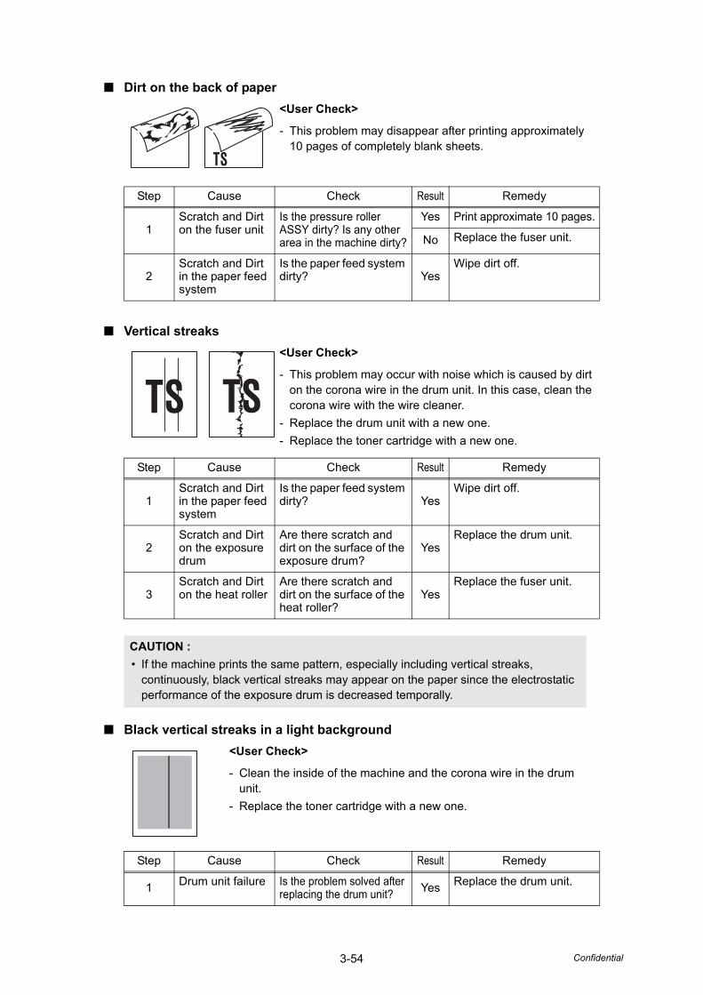
3-54 Confidential
■ Dirt on the back of paper
■ Vertical streaks
■ Black vertical streaks in a light background
<User Check>
- This problem may disappear after printing approximately 10 pages of completely blank sheets.
Step Cause Check Result Remedy
1Scratch and Dirt on the fuser unit
Is the pressure roller ASSY dirty? Is any other area in the machine dirty?
Yes Print approximate 10 pages.
No Replace the fuser unit.
2Scratch and Dirt in the paper feed system
Is the paper feed system dirty? Yes
Wipe dirt off.
<User Check>
- This problem may occur with noise which is caused by dirt on the corona wire in the drum unit. In this case, clean the corona wire with the wire cleaner.
- Replace the drum unit with a new one.- Replace the toner cartridge with a new one.
Step Cause Check Result Remedy
1Scratch and Dirt in the paper feed system
Is the paper feed system dirty? Yes
Wipe dirt off.
2Scratch and Dirt on the exposure drum
Are there scratch and dirt on the surface of the exposure drum?
YesReplace the drum unit.
3Scratch and Dirt on the heat roller
Are there scratch and dirt on the surface of the heat roller?
YesReplace the fuser unit.
CAUTION :• If the machine prints the same pattern, especially including vertical streaks,
continuously, black vertical streaks may appear on the paper since the electrostatic performance of the exposure drum is decreased temporally.
<User Check>
- Clean the inside of the machine and the corona wire in the drum unit.
- Replace the toner cartridge with a new one.
Step Cause Check Result Remedy
1 Drum unit failure Is the problem solved after replacing the drum unit? Yes Replace the drum unit.
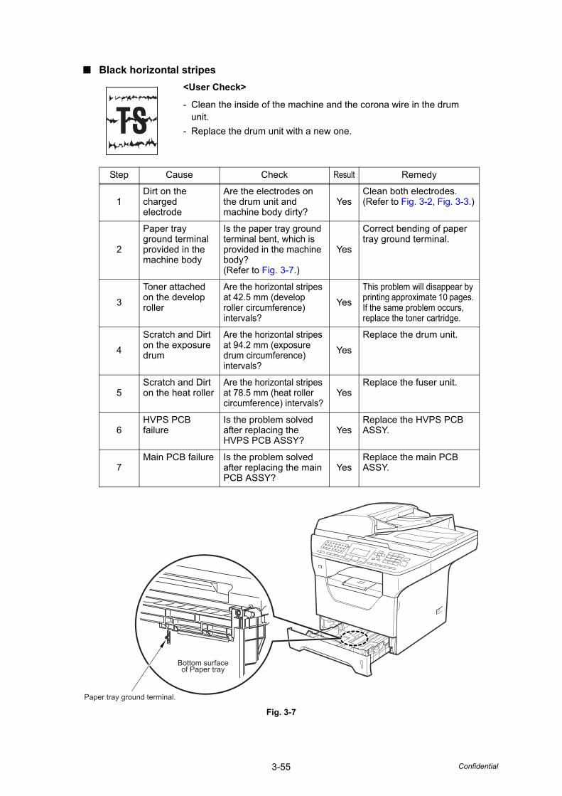
3-55 Confidential
■ Black horizontal stripes
Fig. 3-7
<User Check>
- Clean the inside of the machine and the corona wire in the drum unit.
- Replace the drum unit with a new one.
Step Cause Check Result Remedy
1Dirt on the charged electrode
Are the electrodes on the drum unit and machine body dirty?
YesClean both electrodes.(Refer to Fig. 3-2, Fig. 3-3.)
2
Paper tray ground terminal provided in the machine body
Is the paper tray ground terminal bent, which is provided in the machine body? (Refer to Fig. 3-7.)
Yes
Correct bending of paper tray ground terminal.
3Toner attached on the develop roller
Are the horizontal stripes at 42.5 mm (develop roller circumference) intervals?
YesThis problem will disappear by printing approximate 10 pages. If the same problem occurs, replace the toner cartridge.
4Scratch and Dirt on the exposure drum
Are the horizontal stripes at 94.2 mm (exposure drum circumference) intervals?
YesReplace the drum unit.
5Scratch and Dirt on the heat roller
Are the horizontal stripes at 78.5 mm (heat roller circumference) intervals?
YesReplace the fuser unit.
6HVPS PCB failure
Is the problem solved after replacing the HVPS PCB ASSY?
YesReplace the HVPS PCB ASSY.
7Main PCB failure Is the problem solved
after replacing the main PCB ASSY?
YesReplace the main PCB ASSY.
Bottom surfaceof Paper tray
Paper tray ground terminal.
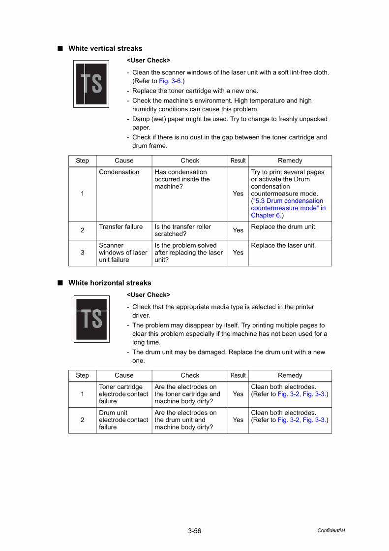
3-56 Confidential
■ White vertical streaks
■ White horizontal streaks
<User Check>
- Clean the scanner windows of the laser unit with a soft lint-free cloth.(Refer to Fig. 3-6.)
- Replace the toner cartridge with a new one.- Check the machine’s environment. High temperature and high
humidity conditions can cause this problem.- Damp (wet) paper might be used. Try to change to freshly unpacked
paper.- Check if there is no dust in the gap between the toner cartridge and
drum frame.
Step Cause Check Result Remedy
1
Condensation Has condensation occurred inside the machine?
Yes
Try to print several pages or activate the Drum condensation countermeasure mode.("5.3 Drum condensation countermeasure mode" in Chapter 6.)
2 Transfer failure Is the transfer roller scratched? Yes Replace the drum unit.
3Scanner windows of laser unit failure
Is the problem solved after replacing the laser unit?
YesReplace the laser unit.
<User Check>
- Check that the appropriate media type is selected in the printer driver.
- The problem may disappear by itself. Try printing multiple pages to clear this problem especially if the machine has not been used for a long time.
- The drum unit may be damaged. Replace the drum unit with a new one.
Step Cause Check Result Remedy
1Toner cartridge electrode contact failure
Are the electrodes on the toner cartridge and machine body dirty?
YesClean both electrodes. (Refer to Fig. 3-2, Fig. 3-3.)
2Drum unit electrode contact failure
Are the electrodes on the drum unit and machine body dirty?
YesClean both electrodes. (Refer to Fig. 3-2, Fig. 3-3.)
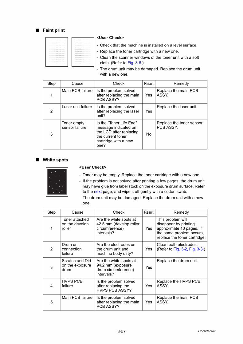
3-57 Confidential
■ Faint print
■ White spots
<User Check>
- Check that the machine is installed on a level surface.- Replace the toner cartridge with a new one.- Clean the scanner windows of the toner unit with a soft
cloth. (Refer to Fig. 3-6.)- The drum unit may be damaged. Replace the drum unit
with a new one.
Step Cause Check Result Remedy
1Main PCB failure Is the problem solved
after replacing the main PCB ASSY?
YesReplace the main PCB ASSY.
2Laser unit failure Is the problem solved
after replacing the laser unit?
YesReplace the laser unit.
3
Toner empty sensor failure
Is the "Toner Life End" message indicated on the LCD after replacing the current toner cartridge with a new one?
No
Replace the toner sensor PCB ASSY.
<User Check>
- Toner may be empty. Replace the toner cartridge with a new one.- If the problem is not solved after printing a few pages, the drum unit
may have glue from label stock on the exposure drum surface. Refer to the next page, and wipe it off gently with a cotton swab.
- The drum unit may be damaged. Replace the drum unit with a new one.
Step Cause Check Result Remedy
1
Toner attached on the develop roller
Are the white spots at 42.5 mm (develop roller circumference) intervals?
Yes
This problem will disappear by printing approximate 10 pages. If the same problem occurs, replace the toner cartridge.
2Drum unit connection failure
Are the electrodes on the drum unit and machine body dirty?
YesClean both electrodes. (Refer to Fig. 3-2, Fig. 3-3.)
3Scratch and Dirt on the exposure drum
Are the white spots at 94.2 mm (exposure drum circumference) intervals?
YesReplace the drum unit.
4HVPS PCB failure
Is the problem solved after replacing the HVPS PCB ASSY?
YesReplace the HVPS PCB ASSY.
5Main PCB failure Is the problem solved
after replacing the main PCB ASSY?
YesReplace the main PCB ASSY.
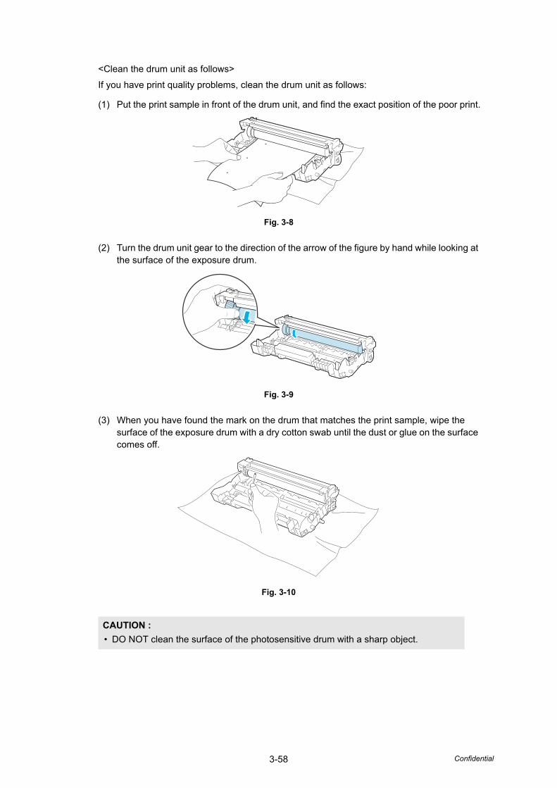
3-58 Confidential
<Clean the drum unit as follows>
If you have print quality problems, clean the drum unit as follows:
(1) Put the print sample in front of the drum unit, and find the exact position of the poor print.
Fig. 3-8
(2) Turn the drum unit gear to the direction of the arrow of the figure by hand while looking at the surface of the exposure drum.
Fig. 3-9
(3) When you have found the mark on the drum that matches the print sample, wipe the surface of the exposure drum with a dry cotton swab until the dust or glue on the surface comes off.
Fig. 3-10
CAUTION :• DO NOT clean the surface of the photosensitive drum with a sharp object.
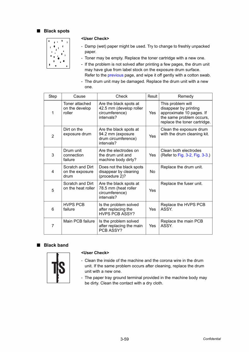
3-59 Confidential
■ Black spots
■ Black band
<User Check>
- Damp (wet) paper might be used. Try to change to freshly unpacked paper.
- Toner may be empty. Replace the toner cartridge with a new one.- If the problem is not solved after printing a few pages, the drum unit
may have glue from label stock on the exposure drum surface.Refer to the previous page, and wipe it off gently with a cotton swab.
- The drum unit may be damaged. Replace the drum unit with a new one.
Step Cause Check Result Remedy
1
Toner attached on the develop roller
Are the black spots at 42.5 mm (develop roller circumference) intervals?
Yes
This problem will disappear by printing approximate 10 pages. If the same problem occurs, replace the toner cartridge.
2Dirt on the exposure drum
Are the black spots at 94.2 mm (exposure drum circumference) intervals?
YesClean the exposure drum with the drum cleaning kit.
3Drum unit connection failure
Are the electrodes on the drum unit and machine body dirty?
YesClean both electrodes (Refer to Fig. 3-2, Fig. 3-3.)
4Scratch and Dirt on the exposure drum
Does not the black spots disappear by cleaning (procedure 2)?
NoReplace the drum unit.
5Scratch and Dirt on the heat roller
Are the black spots at 78.5 mm (heat roller circumference) intervals?
YesReplace the fuser unit.
6HVPS PCB failure
Is the problem solved after replacing the HVPS PCB ASSY?
YesReplace the HVPS PCB ASSY.
7Main PCB failure Is the problem solved
after replacing the main PCB ASSY?
YesReplace the main PCB ASSY.
<User Check>
- Clean the inside of the machine and the corona wire in the drum unit. If the same problem occurs after cleaning, replace the drum unit with a new one.
- The paper tray ground terminal provided in the machine body may be dirty. Clean the contact with a dry cloth.
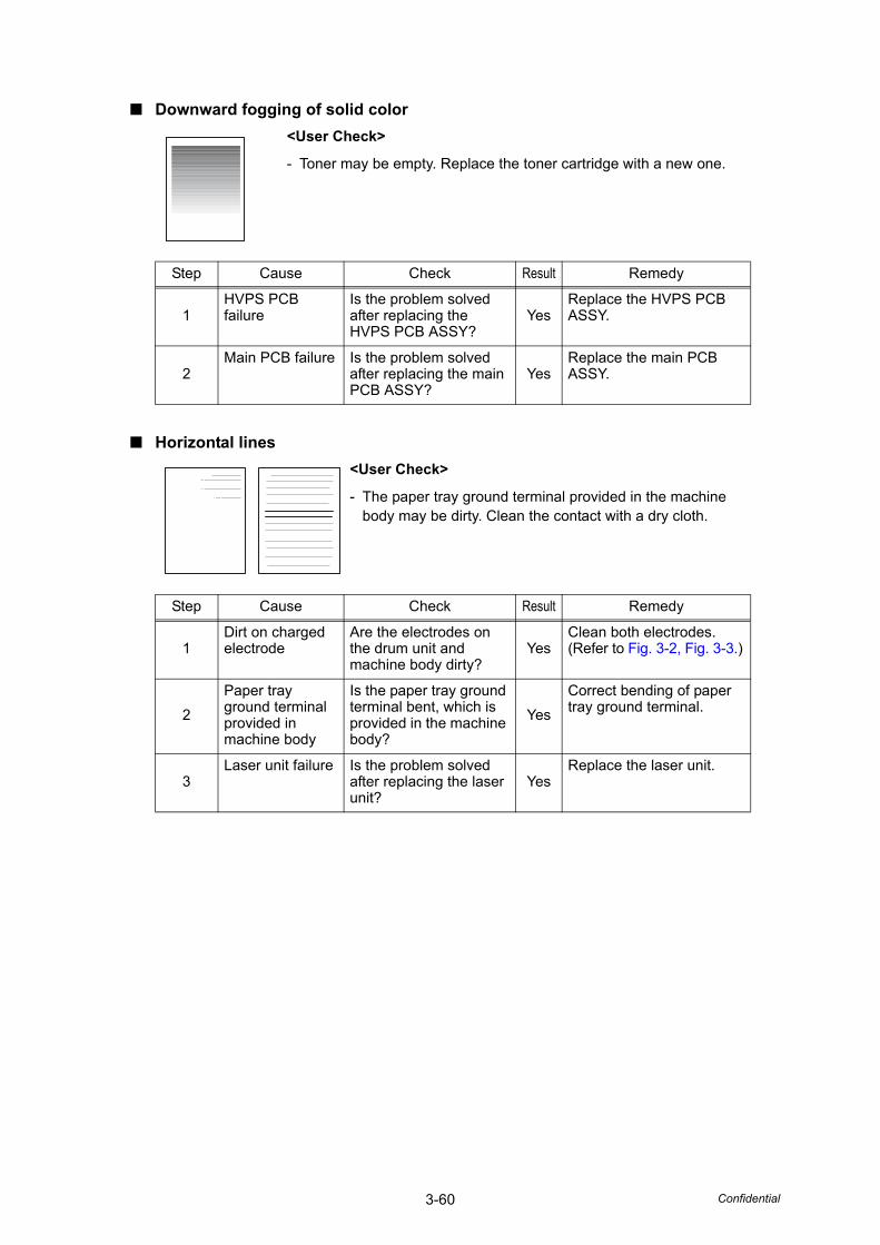
3-60 Confidential
■ Downward fogging of solid color
■ Horizontal lines
<User Check>
- Toner may be empty. Replace the toner cartridge with a new one.
Step Cause Check Result Remedy
1HVPS PCB failure
Is the problem solved after replacing the HVPS PCB ASSY?
YesReplace the HVPS PCB ASSY.
2Main PCB failure Is the problem solved
after replacing the main PCB ASSY?
YesReplace the main PCB ASSY.
<User Check>
- The paper tray ground terminal provided in the machine body may be dirty. Clean the contact with a dry cloth.
Step Cause Check Result Remedy
1Dirt on charged electrode
Are the electrodes on the drum unit and machine body dirty?
YesClean both electrodes. (Refer to Fig. 3-2, Fig. 3-3.)
2Paper tray ground terminal provided in machine body
Is the paper tray ground terminal bent, which is provided in the machine body?
YesCorrect bending of paper tray ground terminal.
3Laser unit failure Is the problem solved
after replacing the laser unit?
YesReplace the laser unit.
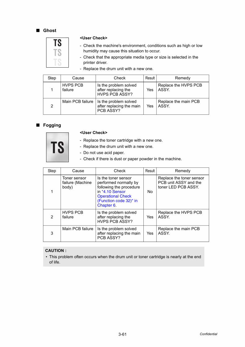
3-61 Confidential
■ Ghost
■ Fogging
<User Check>
- Check the machine's environment, conditions such as high or low humidity may cause this situation to occur.
- Check that the appropriate media type or size is selected in the printer driver.
- Replace the drum unit with a new one.
Step Cause Check Result Remedy
1HVPS PCB failure
Is the problem solved after replacing the HVPS PCB ASSY?
YesReplace the HVPS PCB ASSY.
2Main PCB failure Is the problem solved
after replacing the main PCB ASSY?
YesReplace the main PCB ASSY.
<User Check>
- Replace the toner cartridge with a new one.- Replace the drum unit with a new one.- Do not use acid paper.- Check if there is dust or paper powder in the machine.
Step Cause Check Result Remedy
1
Toner sensor failure (Machine body)
Is the toner sensor performed normally by following the procedure in "4.10 Sensor Operational Check (Function code 32)" in Chapter 6.
No
Replace the toner sensor PCB unit ASSY and the toner LED PCB ASSY.
2HVPS PCB failure
Is the problem solved after replacing the HVPS PCB ASSY?
YesReplace the HVPS PCB ASSY.
3Main PCB failure Is the problem solved
after replacing the main PCB ASSY?
YesReplace the main PCB ASSY.
CAUTION :• This problem often occurs when the drum unit or toner cartridge is nearly at the end
of life.
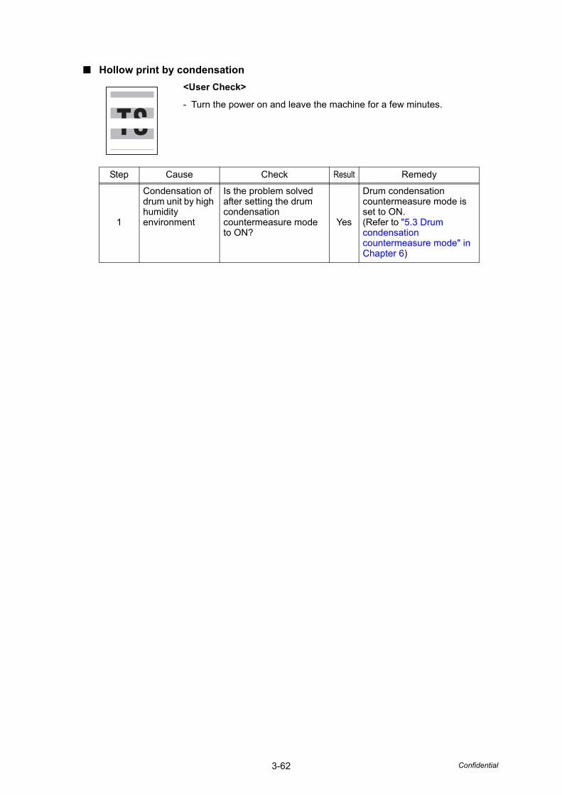
3-62 Confidential
■ Hollow print by condensation<User Check>
- Turn the power on and leave the machine for a few minutes.
Step Cause Check Result Remedy
1
Condensation of drum unit by high humidity environment
Is the problem solved after setting the drum condensation countermeasure mode to ON?
Yes
Drum condensation countermeasure mode is set to ON.(Refer to "5.3 Drum condensation countermeasure mode" in Chapter 6)
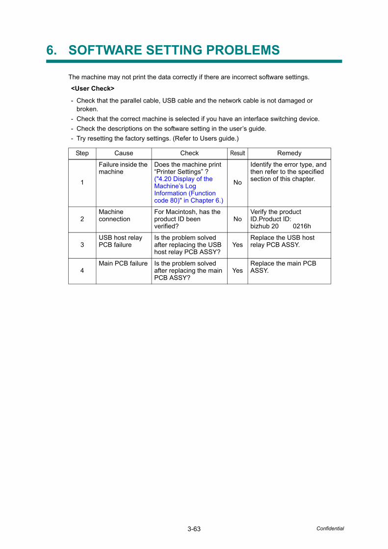
3-63 Confidential
6. SOFTWARE SETTING PROBLEMS
The machine may not print the data correctly if there are incorrect software settings.
<User Check>
- Check that the parallel cable, USB cable and the network cable is not damaged or broken.
- Check that the correct machine is selected if you have an interface switching device.- Check the descriptions on the software setting in the user’s guide.- Try resetting the factory settings. (Refer to Users guide.)
Step Cause Check Result Remedy
1
Failure inside the machine
Does the machine print “Printer Settings” ? ("4.20 Display of the Machine’s Log Information (Function code 80)" in Chapter 6.)
No
Identify the error type, and then refer to the specified section of this chapter.
2Machine connection
For Macintosh, has the product ID been verified?
NoVerify the product ID.Product ID:bizhub 20 0216h
3USB host relayPCB failure
Is the problem solved after replacing the USB host relay PCB ASSY?
YesReplace the USB host relay PCB ASSY.
4Main PCB failure Is the problem solved
after replacing the main PCB ASSY?
YesReplace the main PCB ASSY.

3-64 Confidential
7. NETWORK PROBLEMS
<User Check>
- Check the descriptions in the network user’s guide.- Try resetting the factory settings.
Step Cause Check Result Remedy
1Main PCB failure Is the problem solved
after replacing the main PCB ASSY?
YesReplace the main PCB ASSY.
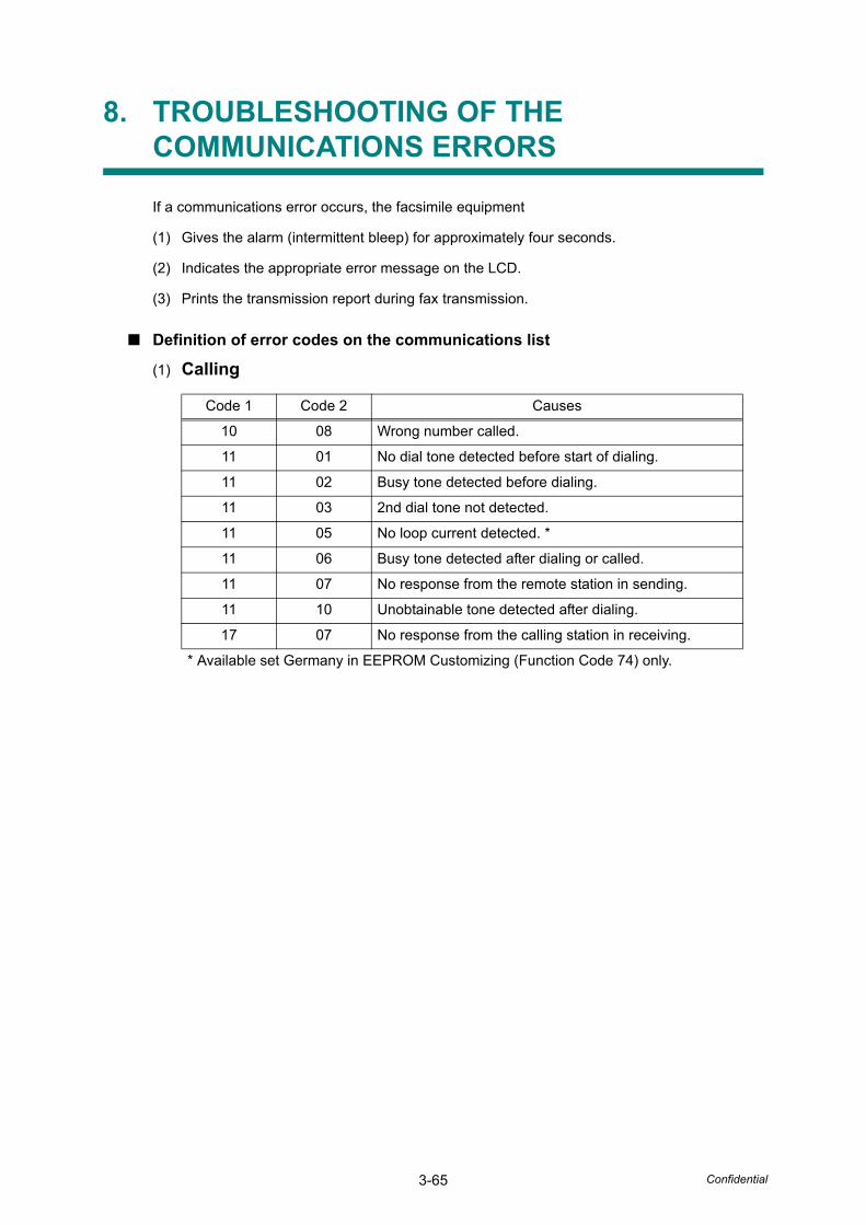
3-65 Confidential
8. TROUBLESHOOTING OF THE COMMUNICATIONS ERRORS
If a communications error occurs, the facsimile equipment
(1) Gives the alarm (intermittent bleep) for approximately four seconds.
(2) Indicates the appropriate error message on the LCD.
(3) Prints the transmission report during fax transmission.
■ Definition of error codes on the communications list
(1) Calling
Code 1 Code 2 Causes
10 08 Wrong number called.
11 01 No dial tone detected before start of dialing.
11 02 Busy tone detected before dialing.
11 03 2nd dial tone not detected.
11 05 No loop current detected. *
11 06 Busy tone detected after dialing or called.
11 07 No response from the remote station in sending.
11 10 Unobtainable tone detected after dialing.
17 07 No response from the calling station in receiving.
* Available set Germany in EEPROM Customizing (Function Code 74) only.
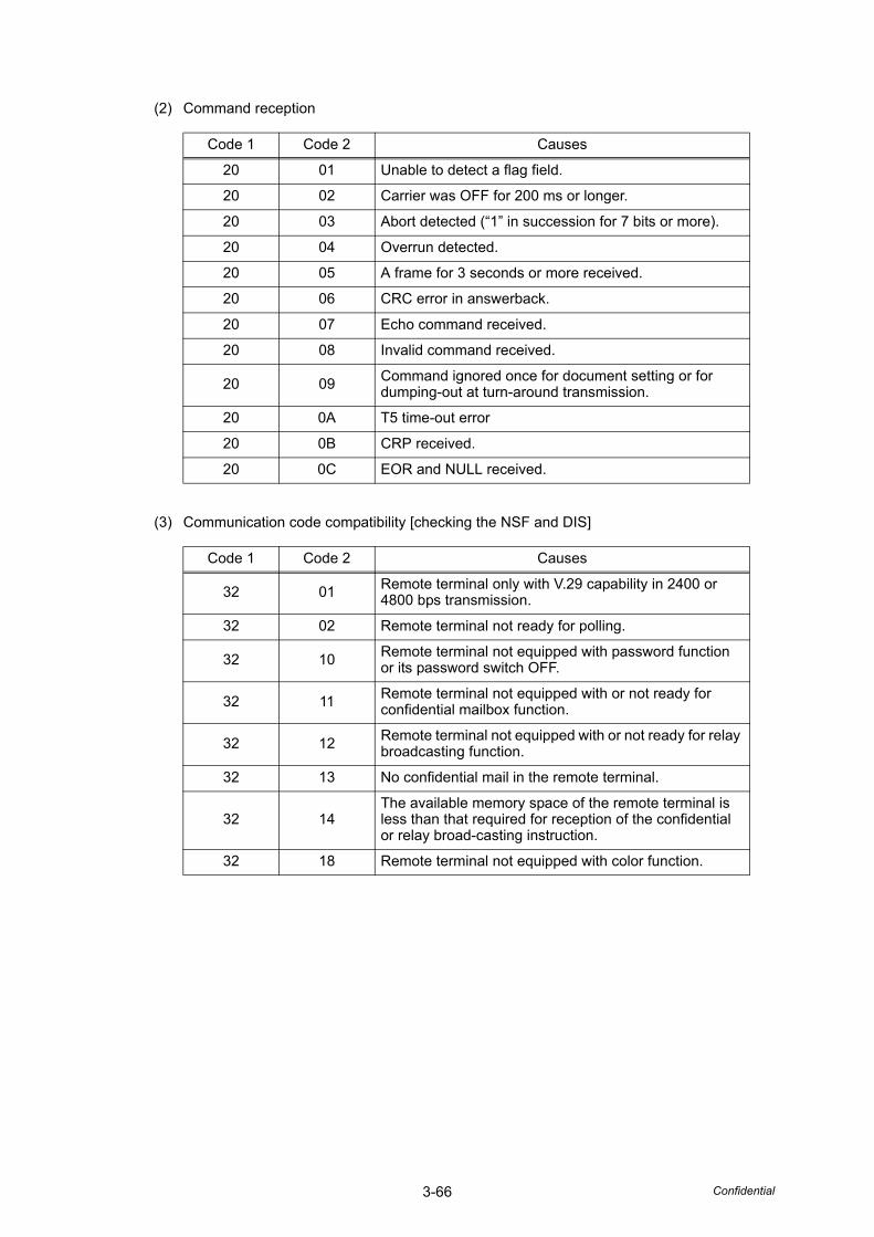
3-66 Confidential
(2) Command reception
(3) Communication code compatibility [checking the NSF and DIS]
Code 1 Code 2 Causes
20 01 Unable to detect a flag field.
20 02 Carrier was OFF for 200 ms or longer.
20 03 Abort detected (“1” in succession for 7 bits or more).
20 04 Overrun detected.
20 05 A frame for 3 seconds or more received.
20 06 CRC error in answerback.
20 07 Echo command received.
20 08 Invalid command received.
20 09 Command ignored once for document setting or for dumping-out at turn-around transmission.
20 0A T5 time-out error
20 0B CRP received.
20 0C EOR and NULL received.
Code 1 Code 2 Causes
32 01 Remote terminal only with V.29 capability in 2400 or 4800 bps transmission.
32 02 Remote terminal not ready for polling.
32 10 Remote terminal not equipped with password function or its password switch OFF.
32 11 Remote terminal not equipped with or not ready for confidential mailbox function.
32 12 Remote terminal not equipped with or not ready for relay broadcasting function.
32 13 No confidential mail in the remote terminal.
32 14The available memory space of the remote terminal is less than that required for reception of the confidential or relay broad-casting instruction.
32 18 Remote terminal not equipped with color function.
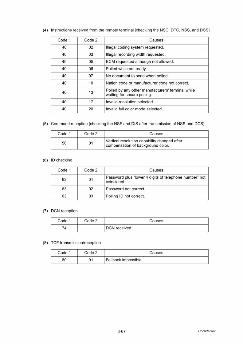
3-67 Confidential
(4) Instructions received from the remote terminal [checking the NSC, DTC, NSS, and DCS]
(5) Command reception [checking the NSF and DIS after transmission of NSS and DCS]
(6) ID checking
(7) DCN reception
(8) TCF transmission/reception
Code 1 Code 2 Causes
40 02 Illegal coding system requested.
40 03 Illegal recording width requested.
40 05 ECM requested although not allowed.
40 06 Polled while not ready.
40 07 No document to send when polled.
40 10 Nation code or manufacturer code not correct.
40 13 Polled by any other manufacturers' terminal while waiting for secure polling.
40 17 Invalid resolution selected.
40 20 Invalid full color mode selected.
Code 1 Code 2 Causes
50 01 Vertical resolution capability changed after compensation of background color.
Code 1 Code 2 Causes
63 01 Password plus “lower 4 digits of telephone number” notcoincident.
63 02 Password not correct.
63 03 Polling ID not correct.
Code 1 Code 2 Causes
74 DCN received.
Code 1 Code 2 Causes
80 01 Fallback impossible.
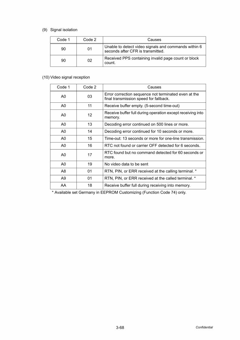
3-68 Confidential
(9) Signal isolation
(10) Video signal reception
Code 1 Code 2 Causes
90 01 Unable to detect video signals and commands within 6 seconds after CFR is transmitted.
90 02 Received PPS containing invalid page count or block count.
Code 1 Code 2 Causes
A0 03 Error correction sequence not terminated even at the final transmission speed for fallback.
A0 11 Receive buffer empty. (5-second time-out)
A0 12 Receive buffer full during operation except receiving into memory.
A0 13 Decoding error continued on 500 lines or more.
A0 14 Decoding error continued for 10 seconds or more.
A0 15 Time-out: 13 seconds or more for one-line transmission.
A0 16 RTC not found or carrier OFF detected for 6 seconds.
A0 17 RTC found but no command detected for 60 seconds or more.
A0 19 No video data to be sent
A8 01 RTN, PIN, or ERR received at the calling terminal. *
A9 01 RTN, PIN, or ERR received at the called terminal. *
AA 18 Receive buffer full during receiving into memory.
* Available set Germany in EEPROM Customizing (Function Code 74) only.
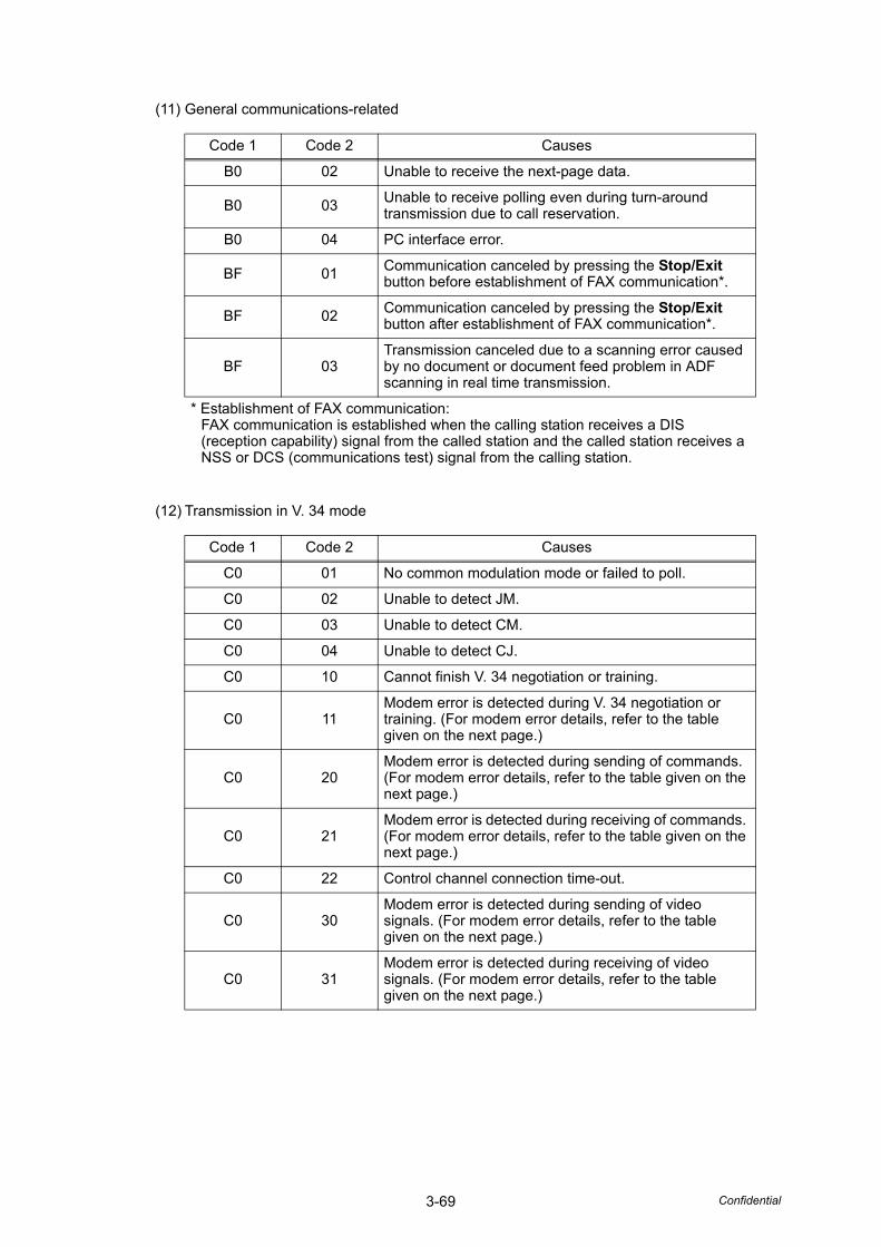
3-69 Confidential
(11) General communications-related
(12) Transmission in V. 34 mode
Code 1 Code 2 Causes
B0 02 Unable to receive the next-page data.
B0 03 Unable to receive polling even during turn-around transmission due to call reservation.
B0 04 PC interface error.
BF 01 Communication canceled by pressing the Stop/Exit button before establishment of FAX communication*.
BF 02 Communication canceled by pressing the Stop/Exit button after establishment of FAX communication*.
BF 03Transmission canceled due to a scanning error caused by no document or document feed problem in ADF scanning in real time transmission.
* Establishment of FAX communication:FAX communication is established when the calling station receives a DIS (reception capability) signal from the called station and the called station receives a NSS or DCS (communications test) signal from the calling station.
Code 1 Code 2 Causes
C0 01 No common modulation mode or failed to poll.
C0 02 Unable to detect JM.
C0 03 Unable to detect CM.
C0 04 Unable to detect CJ.
C0 10 Cannot finish V. 34 negotiation or training.
C0 11Modem error is detected during V. 34 negotiation or training. (For modem error details, refer to the table given on the next page.)
C0 20Modem error is detected during sending of commands. (For modem error details, refer to the table given on the next page.)
C0 21Modem error is detected during receiving of commands. (For modem error details, refer to the table given on the next page.)
C0 22 Control channel connection time-out.
C0 30Modem error is detected during sending of video signals. (For modem error details, refer to the table given on the next page.)
C0 31Modem error is detected during receiving of video signals. (For modem error details, refer to the table given on the next page.)

3-70 Confidential
(13) Maintenance mode
(14) Machine error
Code 1 Code 2 Causes
E0 01 Failed to detect 1300 Hz signal in burn-in operation.
E0 02 Failed to detect PB signals in burn-in operation.
Code 1 Code 2 Causes
FF X X Machine error(For X X, refer to "2.1 ERROR INDICATION")
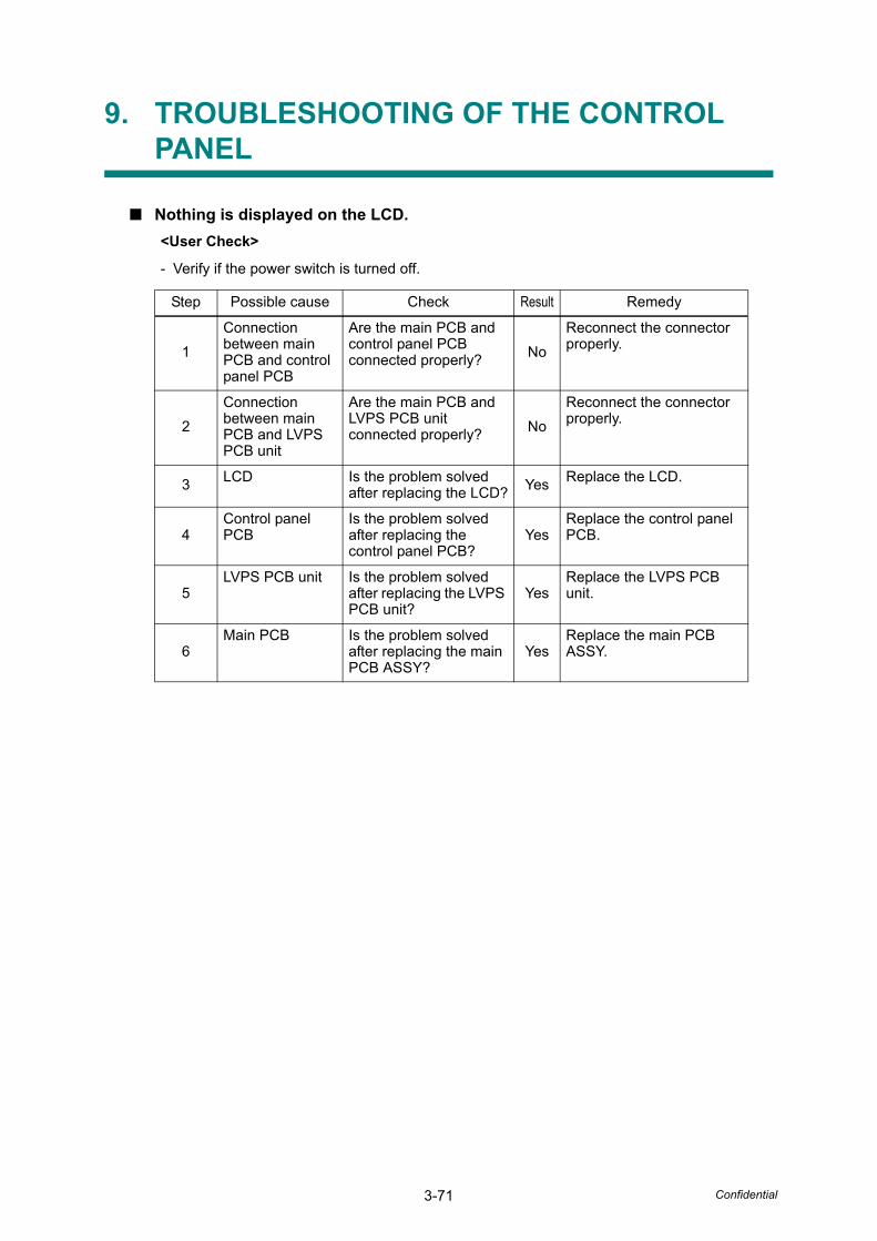
3-71 Confidential
9. TROUBLESHOOTING OF THE CONTROL PANEL
■ Nothing is displayed on the LCD.<User Check>
- Verify if the power switch is turned off.
Step Possible cause Check Result Remedy
1Connection between main PCB and control panel PCB
Are the main PCB and control panel PCB connected properly? No
Reconnect the connector properly.
2Connection between main PCB and LVPS PCB unit
Are the main PCB and LVPS PCB unit connected properly? No
Reconnect the connector properly.
3 LCD Is the problem solved after replacing the LCD? Yes Replace the LCD.
4Control panel PCB
Is the problem solved after replacing the control panel PCB?
YesReplace the control panel PCB.
5LVPS PCB unit Is the problem solved
after replacing the LVPS PCB unit?
YesReplace the LVPS PCB unit.
6Main PCB Is the problem solved
after replacing the main PCB ASSY?
YesReplace the main PCB ASSY.
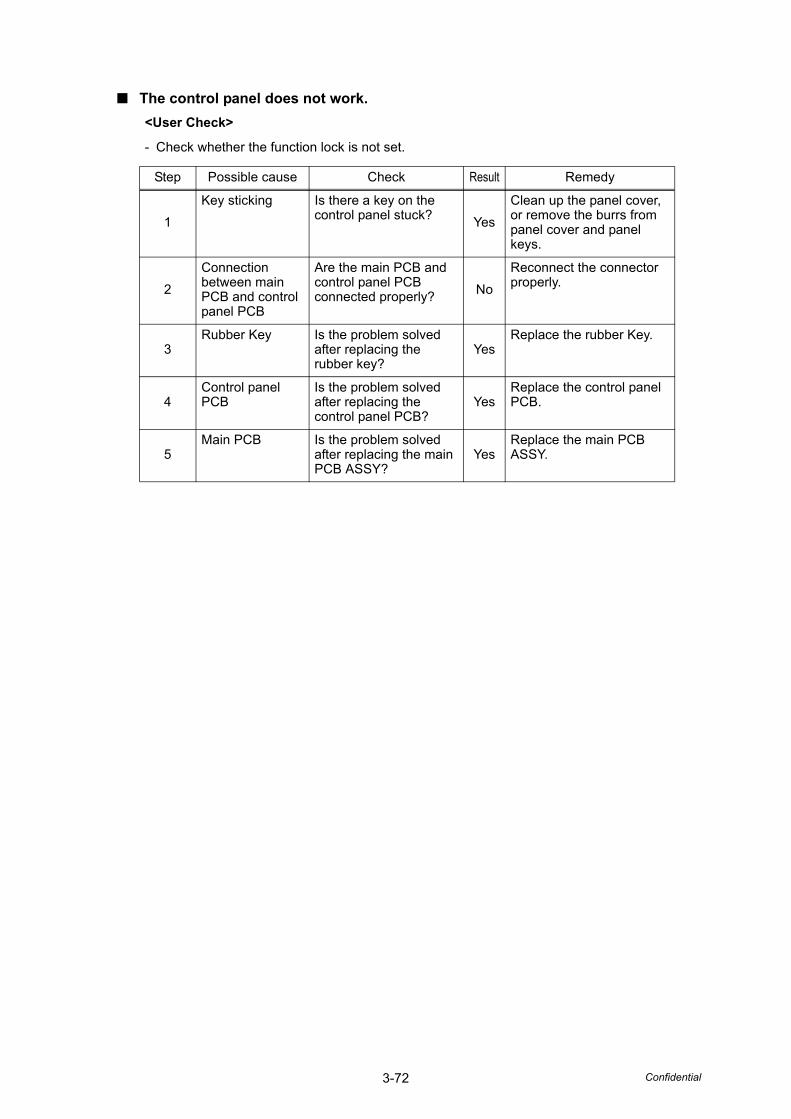
3-72 Confidential
■ The control panel does not work.<User Check>
- Check whether the function lock is not set.
Step Possible cause Check Result Remedy
1Key sticking Is there a key on the
control panel stuck? YesClean up the panel cover, or remove the burrs from panel cover and panel keys.
2Connection between main PCB and control panel PCB
Are the main PCB and control panel PCB connected properly? No
Reconnect the connector properly.
3Rubber Key Is the problem solved
after replacing the rubber key?
YesReplace the rubber Key.
4Control panel PCB
Is the problem solved after replacing the control panel PCB?
YesReplace the control panel PCB.
5Main PCB Is the problem solved
after replacing the main PCB ASSY?
YesReplace the main PCB ASSY.
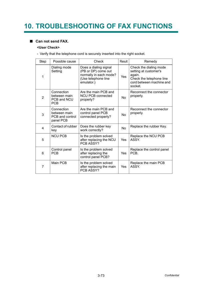
3-73 Confidential
10. TROUBLESHOOTING OF FAX FUNCTIONS
■ Can not send FAX. <User Check>
- Verify that the telephone cord is securely inserted into the right socket.
Step Possible cause Check Result Remedy
1
Dialing mode Setting
Does a dialing signal (PB or DP) come out normally in each mode? (Use telephone line emulator.)
Yes
Check the dialing mode setting at customer's again.Check the telephone line cord between machine and socket.
2Connection between main PCB and NCU PCB
Are the main PCB and NCU PCB connected properly? No
Reconnect the connector properly.
3Connection between main PCB and control panel PCB
Are the main PCB and control panel PCB connected properly? No
Reconnect the connector properly.
4 Contact of rubber key
Does the rubber key work correctly? No Replace the rubber Key.
5NCU PCB Is the problem solved
after replacing the NCU PCB ASSY?
YesReplace the NCU PCB ASSY.
6Control panel PCB
Is the problem solved after replacing the control panel PCB?
YesReplace the control panel PCB.
7Main PCB Is the problem solved
after replacing the main PCB ASSY?
YesReplace the main PCB ASSY.
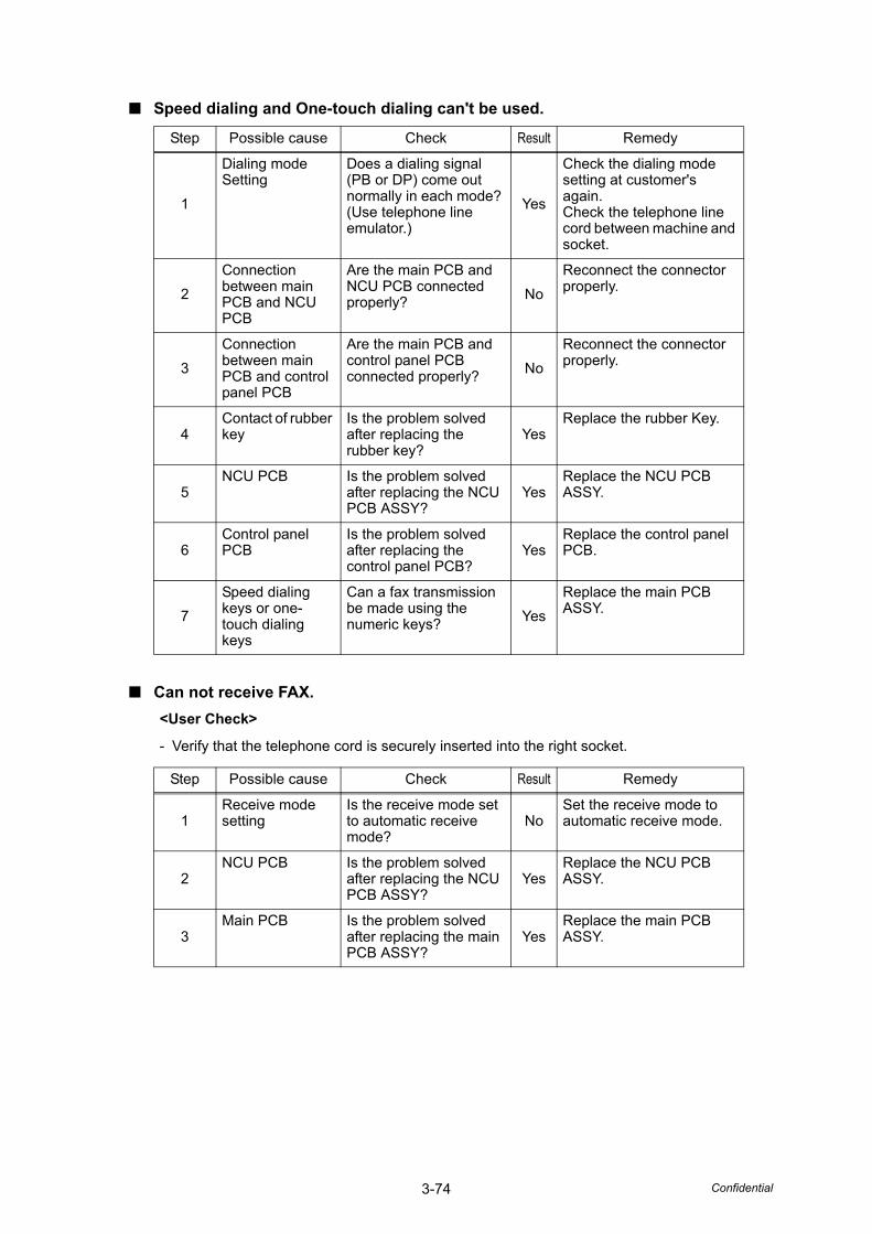
3-74 Confidential
■ Speed dialing and One-touch dialing can't be used.
■ Can not receive FAX.
Step Possible cause Check Result Remedy
1
Dialing mode Setting
Does a dialing signal (PB or DP) come out normally in each mode? (Use telephone line emulator.)
Yes
Check the dialing mode setting at customer's again.Check the telephone line cord between machine and socket.
2Connection between main PCB and NCU PCB
Are the main PCB and NCU PCB connected properly? No
Reconnect the connector properly.
3Connection between main PCB and control panel PCB
Are the main PCB and control panel PCB connected properly? No
Reconnect the connector properly.
4Contact of rubber key
Is the problem solved after replacing the rubber key?
YesReplace the rubber Key.
5NCU PCB Is the problem solved
after replacing the NCU PCB ASSY?
YesReplace the NCU PCB ASSY.
6Control panel PCB
Is the problem solved after replacing the control panel PCB?
YesReplace the control panel PCB.
7Speed dialing keys or one-touch dialing keys
Can a fax transmission be made using the numeric keys? Yes
Replace the main PCB ASSY.
<User Check>
- Verify that the telephone cord is securely inserted into the right socket.
Step Possible cause Check Result Remedy
1Receive mode setting
Is the receive mode set to automatic receive mode?
NoSet the receive mode to automatic receive mode.
2NCU PCB Is the problem solved
after replacing the NCU PCB ASSY?
YesReplace the NCU PCB ASSY.
3Main PCB Is the problem solved
after replacing the main PCB ASSY?
YesReplace the main PCB ASSY.
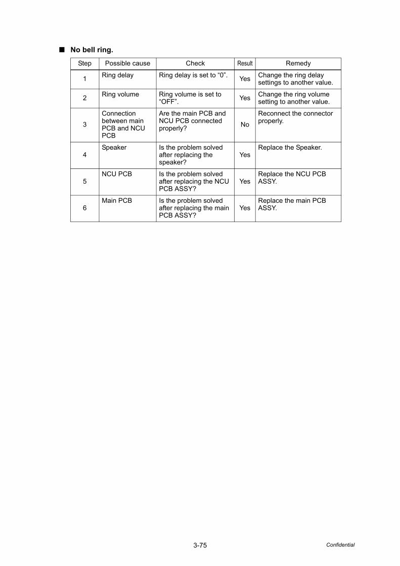
3-75 Confidential
■ No bell ring.
Step Possible cause Check Result Remedy
1 Ring delay Ring delay is set to “0”. Yes Change the ring delay settings to another value.
2 Ring volume Ring volume is set to “OFF”. Yes Change the ring volume
setting to another value.
3Connection between main PCB and NCU PCB
Are the main PCB and NCU PCB connected properly? No
Reconnect the connector properly.
4Speaker Is the problem solved
after replacing the speaker?
YesReplace the Speaker.
5NCU PCB Is the problem solved
after replacing the NCU PCB ASSY?
YesReplace the NCU PCB ASSY.
6Main PCB Is the problem solved
after replacing the main PCB ASSY?
YesReplace the main PCB ASSY.
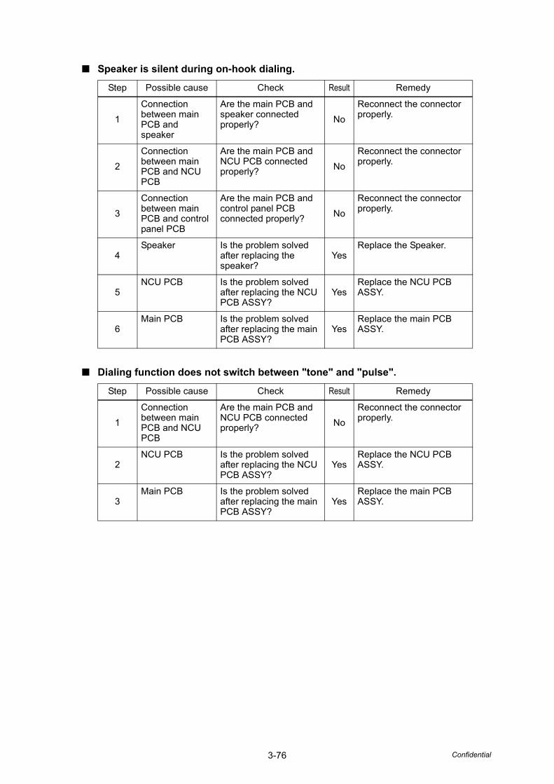
3-76 Confidential
■ Speaker is silent during on-hook dialing.
■ Dialing function does not switch between "tone" and "pulse".
Step Possible cause Check Result Remedy
1Connection between main PCB and speaker
Are the main PCB and speaker connected properly? No
Reconnect the connector properly.
2Connection between main PCB and NCU PCB
Are the main PCB and NCU PCB connected properly? No
Reconnect the connector properly.
3Connection between main PCB and control panel PCB
Are the main PCB and control panel PCB connected properly? No
Reconnect the connector properly.
4Speaker Is the problem solved
after replacing the speaker?
YesReplace the Speaker.
5NCU PCB Is the problem solved
after replacing the NCU PCB ASSY?
YesReplace the NCU PCB ASSY.
6Main PCB Is the problem solved
after replacing the main PCB ASSY?
YesReplace the main PCB ASSY.
Step Possible cause Check Result Remedy
1Connection between main PCB and NCU PCB
Are the main PCB and NCU PCB connected properly? No
Reconnect the connector properly.
2NCU PCB Is the problem solved
after replacing the NCU PCB ASSY?
YesReplace the NCU PCB ASSY.
3Main PCB Is the problem solved
after replacing the main PCB ASSY?
YesReplace the main PCB ASSY.
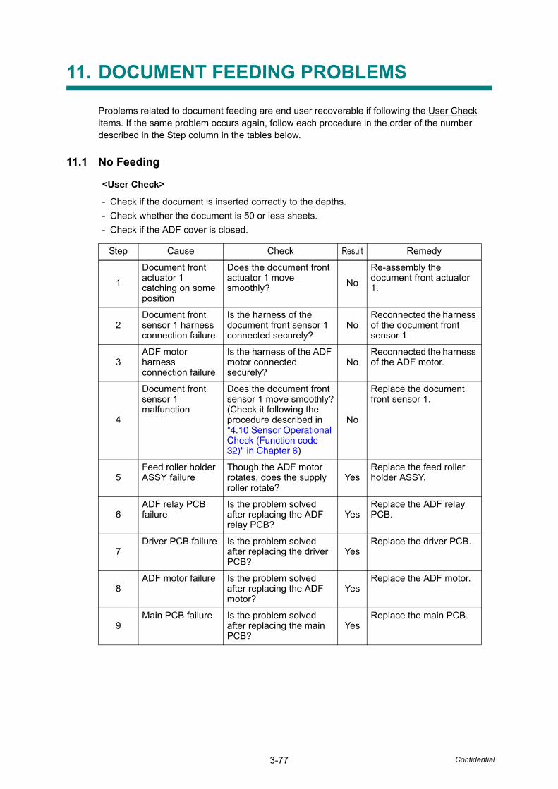
3-77 Confidential
11. DOCUMENT FEEDING PROBLEMS
Problems related to document feeding are end user recoverable if following the User Check items. If the same problem occurs again, follow each procedure in the order of the number described in the Step column in the tables below.
11.1 No Feeding
<User Check>
- Check if the document is inserted correctly to the depths.- Check whether the document is 50 or less sheets.- Check if the ADF cover is closed.
Step Cause Check Result Remedy
1Document front actuator 1 catching on some position
Does the document front actuator 1 move smoothly? No
Re-assembly the document front actuator 1.
2Document front sensor 1 harness connection failure
Is the harness of the document front sensor 1 connected securely?
NoReconnected the harness of the document front sensor 1.
3ADF motor harness connection failure
Is the harness of the ADF motor connected securely?
NoReconnected the harness of the ADF motor.
4
Document front sensor 1 malfunction
Does the document front sensor 1 move smoothly?(Check it following the procedure described in "4.10 Sensor Operational Check (Function code 32)" in Chapter 6)
No
Replace the document front sensor 1.
5Feed roller holder ASSY failure
Though the ADF motor rotates, does the supply roller rotate?
YesReplace the feed roller holder ASSY.
6ADF relay PCB failure
Is the problem solved after replacing the ADF relay PCB?
YesReplace the ADF relay PCB.
7Driver PCB failure Is the problem solved
after replacing the driver PCB?
YesReplace the driver PCB.
8ADF motor failure Is the problem solved
after replacing the ADF motor?
YesReplace the ADF motor.
9Main PCB failure Is the problem solved
after replacing the main PCB?
YesReplace the main PCB.
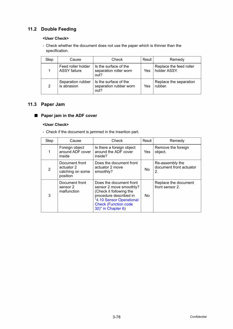
3-78 Confidential
11.2 Double Feeding
11.3 Paper Jam
■ Paper jam in the ADF cover
<User Check>
- Check whether the document does not use the paper which is thinner than the specification.
Step Cause Check Result Remedy
1Feed roller holder ASSY failure
Is the surface of the separation roller worn out?
YesReplace the feed roller holder ASSY.
2Separation rubber is abrasion
Is the surface of the separation rubber worn out?
YesReplace the separation rubber.
<User Check>
- Check if the document is jammed in the insertion part.
Step Cause Check Result Remedy
1Foreign object around ADF cover inside
Is there a foreign object around the ADF cover inside?
YesRemove the foreign object.
2Document front actuator 2 catching on some position
Does the document front actuator 2 move smoothly? No
Re-assembly the document front actuator 2.
3
Document front sensor 2 malfunction
Does the document front sensor 2 move smoothly?(Check it following the procedure described in "4.10 Sensor Operational Check (Function code 32)" in Chapter 6)
No
Replace the document front sensor 2.
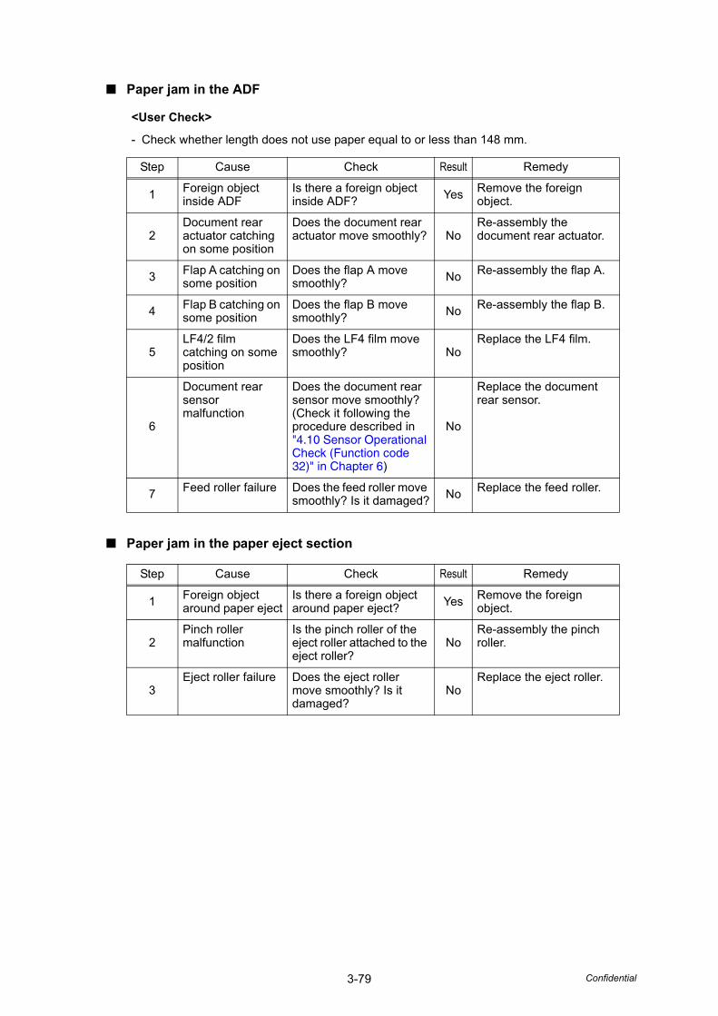
3-79 Confidential
■ Paper jam in the ADF
■ Paper jam in the paper eject section
<User Check>
- Check whether length does not use paper equal to or less than 148 mm.
Step Cause Check Result Remedy
1 Foreign object inside ADF
Is there a foreign object inside ADF? Yes Remove the foreign
object.
2Document rear actuator catching on some position
Does the document rear actuator move smoothly? No
Re-assembly the document rear actuator.
3 Flap A catching on some position
Does the flap A move smoothly? No Re-assembly the flap A.
4 Flap B catching on some position
Does the flap B move smoothly? No Re-assembly the flap B.
5LF4/2 film catching on some position
Does the LF4 film move smoothly? No
Replace the LF4 film.
6
Document rear sensor malfunction
Does the document rear sensor move smoothly?(Check it following the procedure described in "4.10 Sensor Operational Check (Function code 32)" in Chapter 6)
No
Replace the document rear sensor.
7 Feed roller failure Does the feed roller move smoothly? Is it damaged? No Replace the feed roller.
Step Cause Check Result Remedy
1 Foreign object around paper eject
Is there a foreign object around paper eject? Yes Remove the foreign
object.
2Pinch roller malfunction
Is the pinch roller of the eject roller attached to the eject roller?
NoRe-assembly the pinch roller.
3Eject roller failure Does the eject roller
move smoothly? Is it damaged?
NoReplace the eject roller.
3-80 Confidential
■ Paper jam at the duplex scanning
11.4 Wrinkles
<User Check>
- Use the A4 or Letter size.- Use the document without warpage.- Use the document which is not so too thin. (thickness of paper)
Step Cause Check Result Remedy
1 Foreign object inside ADF
Is there a foreign object inside ADF? Yes Remove the foreign
object.
2Switch back sensor actuator catching on some position
Does the switch back sensor actuator move smoothly? No
Re-assembly the switch back sensor actuator.
3 Each flap catching on some position
Does the each flap move smoothly? No Re-assembly the flap.
4
Switch back sensor malfunction
Does the switch back sensor move smoothly?(Check it following the procedure described in "4.10 Sensor Operational Check (Function code 32)" in Chapter 6)
No
Replace the switch back sensor.
5 Flap A failure Does the flap A move smoothly? Is it damaged? No Replace the flap A.
6Switch back solenoid ASSY failure
Does the switch back solenoid ASSY move smoothly?
NoReplace the switch back solenoid ASSY.
7Switch back roller failure
Does the switch back roller move smoothly? Is it damaged?
NoReplace the switch back roller.
<User Check>
- Check if the document is loaded into the ADF correctly.- Check whether the document guide matches the document size.- Check whether the document does not curl.
Step Cause Check Result Remedy
1Feed roller positioning section failure
Is each feed roller attached correctly section?(Check the feed roller position in Page 5-61)
NoRe-assembly each feed roller to the correctly section.
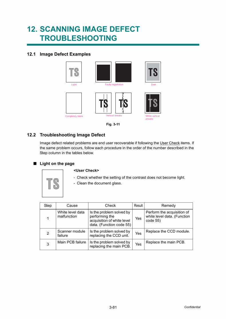
3-81 Confidential
12. SCANNING IMAGE DEFECT TROUBLESHOOTING
12.1 Image Defect Examples
Fig. 3-11
12.2 Troubleshooting Image DefectImage defect related problems are end user recoverable if following the User Check items. If the same problem occurs, follow each procedure in the order of the number described in the Step column in the tables below.
■ Light on the page<User Check>
- Check whether the setting of the contrast does not become light.- Clean the document glass.
Step Cause Check Result Remedy
1White level data malfunction
Is the problem solved by performing the acquisition of white level data. (Function code 55)
YesPerform the acquisition of white level data. (Function code 55)
2 Scanner module failure
Is the problem solved by replacing the CCD unit. Yes Replace the CCD module.
3 Main PCB failure Is the problem solved by replacing the main PCB. Yes Replace the main PCB.
Light
White verticalstreaks
Vertical streaksCompletely blank
Faulty registration Dark
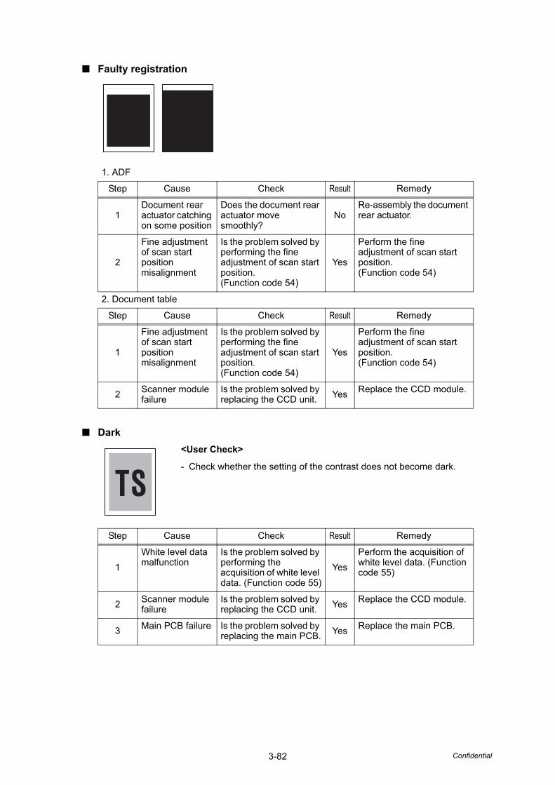
3-82 Confidential
■ Faulty registration
■ Dark
1. ADF
Step Cause Check Result Remedy
1Document rear actuator catching on some position
Does the document rear actuator move smoothly?
NoRe-assembly the document rear actuator.
2
Fine adjustment of scan start position misalignment
Is the problem solved by performing the fine adjustment of scan start position. (Function code 54)
Yes
Perform the fine adjustment of scan start position. (Function code 54)
2. Document table
Step Cause Check Result Remedy
1
Fine adjustment of scan start position misalignment
Is the problem solved by performing the fine adjustment of scan start position. (Function code 54)
Yes
Perform the fine adjustment of scan start position. (Function code 54)
2 Scanner module failure
Is the problem solved by replacing the CCD unit. Yes Replace the CCD module.
<User Check>
- Check whether the setting of the contrast does not become dark.
Step Cause Check Result Remedy
1White level data malfunction
Is the problem solved by performing the acquisition of white level data. (Function code 55)
YesPerform the acquisition of white level data. (Function code 55)
2 Scanner module failure
Is the problem solved by replacing the CCD unit. Yes Replace the CCD module.
3 Main PCB failure Is the problem solved by replacing the main PCB. Yes Replace the main PCB.
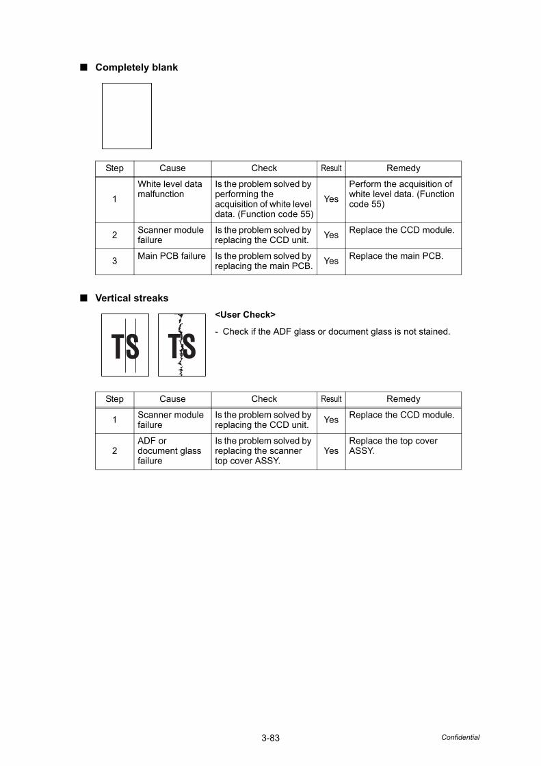
3-83 Confidential
■ Completely blank
■ Vertical streaks
Step Cause Check Result Remedy
1White level data malfunction
Is the problem solved by performing the acquisition of white level data. (Function code 55)
YesPerform the acquisition of white level data. (Function code 55)
2 Scanner module failure
Is the problem solved by replacing the CCD unit. Yes Replace the CCD module.
3 Main PCB failure Is the problem solved by replacing the main PCB. Yes Replace the main PCB.
<User Check>
- Check if the ADF glass or document glass is not stained.
Step Cause Check Result Remedy
1 Scanner module failure
Is the problem solved by replacing the CCD unit. Yes Replace the CCD module.
2ADF or document glass failure
Is the problem solved by replacing the scanner top cover ASSY.
YesReplace the top cover ASSY.
3-84 Confidential
■ White vertical streaks<User Check>
- Check if the ADF glass or document glass is not stained.
Step Cause Check Result Remedy
1 Scanner module failure
Is the problem solved by replacing the CCD unit. Yes Replace the CCD module.
2ADF or document glass failure
Is the problem solved by replacing the scanner top cover ASSY.
YesReplace the top cover ASSY.
3-85 Confidential
13. OTHERS PROBLEMS
■ The machine is not turned on, or the LCD indication does not appear.
■ The fan does not work.
Step Cause Check Result Remedy
1Harness connection failure of LCD panel PCB
Is the harness of the LCD panel PCB ASSY connected correctly? No
Reconnect the LCD panel PCB ASSY harness.
2LCD panel PCB failure
Is the problem solved after replacing the LCD panel PCB ASSY?
YesReplace the LCD panel PCB ASSY.
3LCD panel failure Is the problem solved
after replacing the LCD panel ASSY?
YesReplace the LCD panel ASSY.
4Low-voltage power supply failure
Is the problem solved after replacing the LVPS PCB unit?
YesReplace the LVPS PCB unit.
5Main PCB Is the problem solved
after replacing the main PCB ASSY?
YesReplace the main PCB ASSY.
(Verify the position of each fan referring to "4.19 Operational Check of Fans (Function code 78)" in Chapter 6.)
Step Cause Check Result Remedy
1Harness connection failure of the appropriate fan
Is the harness of the appropriate fan connected correctly? No
Reconnect the harness of the appropriate fan correctly.
2Charge HVPS PCB failure
Is the problem solved after replacing the charge HVPS PCB ASSY?
YesReplace the charge HVPS PCB ASSY. Replace the fuser unit fan (FU) and air intake fan (AIR).
3Low-voltage power supply failure
Is the problem solved after replacing the LVPS PCB unit?
YesReplace the LVPS PCB unit. Replace the LVPS fan (PS).
4Main PCB Is the problem solved
after replacing the main PCB ASSY?
YesReplace the main PCB ASSY.
3-86 Confidential
■ Pickup function of paper tray does not work.
■ The new toner is not detected.
■ Printing from Macintosh applications fails.
■ USB direct printing does not work.
Step Cause Remedy
1 Lift arm catching on some position Re-assemble the lift arm.
2 Pickup roller holder ASSY catching on some position
Re-assemble the pickup roller holder ASSY catching on some position.
3 Roller holder ASSY failure Replace the roller holder ASSY.
4 Main motor failure Replace the main motor.
5 Pressure plate drive cam failure Replace the frame L.
6 Main PCB ASSY failure Replace the main PCB ASSY.
Step Cause Remedy
1 New toner actuator not operating smoothly or catching.
Make sure correct movement of the new toner actuator.
2 New toner actuator damaged Replace the drum unit.
3 Main PCB failure Replace the main PCB ASSY.
4 Toner sensor (TE/NEW) failure Replace the relay front PCB ASSY (TE/NEW).
<User Check>
- Check that the printer driver which, is supplied with the product, is installed in Library/ Printers, and that the print queue is created.
- Check the connecting end on the printer browser. It must be matched with the connecting end which is actually connected.
Step Possible cause Check Result Remedy
1
Failure inside the machine
Does the machine print test pattern? (Check it following the procedure described in "4.5 Test Pattern 1 (Function code 09)" in Chapter 6.)
No
Identify the error type, and then refer to the specified section of this chapter.
2Breakage of main PCB
Does the machine make a print using a correct PC and a USB cable?
NoReplace the main PCB ASSY.
Step Cause Remedy
1 USB host PCB failure Replace the USB host PCB.
2 Main PCB failure Replace the main PCB ASSY.

Confidential
CHAPTER 4PERIODICAL MAINTENANCE

Confidential
CHAPTER 4 PERIODICAL MAINTENANCE
CONTENTS1. PERIODICAL MAINTENANCE PARTS ........................................................................4-1
1.1 Periodical Maintenance Parts................................................................................4-2
1.2 Procedures to Replace Periodical Maintenance Parts ..........................................4-3
1.2.1 Fuser unit and laser unit.............................................................................4-3
1.2.2 Paper feeding kit for tray 1, 2 ...................................................................4-30
1.2.3 Paper feeding kit for MP tray....................................................................4-36
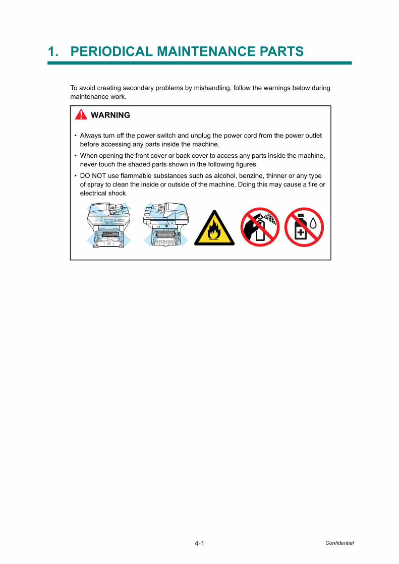
4-1 Confidential
1. PERIODICAL MAINTENANCE PARTS
To avoid creating secondary problems by mishandling, follow the warnings below during maintenance work.
WARNING
• Always turn off the power switch and unplug the power cord from the power outlet before accessing any parts inside the machine.
• When opening the front cover or back cover to access any parts inside the machine, never touch the shaded parts shown in the following figures.
• DO NOT use flammable substances such as alcohol, benzine, thinner or any type of spray to clean the inside or outside of the machine. Doing this may cause a fire or electrical shock.
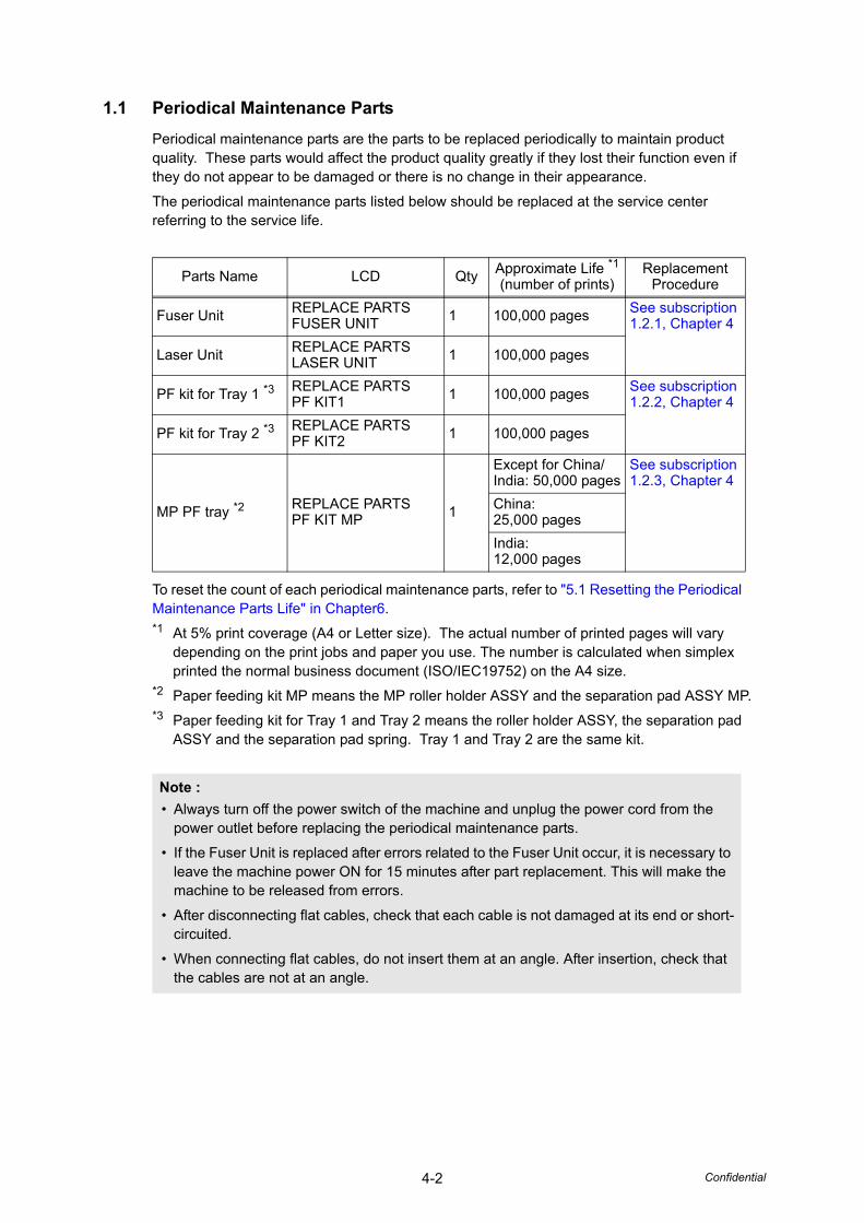
4-2 Confidential
1.1 Periodical Maintenance PartsPeriodical maintenance parts are the parts to be replaced periodically to maintain product quality. These parts would affect the product quality greatly if they lost their function even if they do not appear to be damaged or there is no change in their appearance.
The periodical maintenance parts listed below should be replaced at the service center referring to the service life.
To reset the count of each periodical maintenance parts, refer to "5.1 Resetting the Periodical Maintenance Parts Life" in Chapter6.*1 At 5% print coverage (A4 or Letter size). The actual number of printed pages will vary
depending on the print jobs and paper you use. The number is calculated when simplex printed the normal business document (ISO/IEC19752) on the A4 size.
*2 Paper feeding kit MP means the MP roller holder ASSY and the separation pad ASSY MP.*3 Paper feeding kit for Tray 1 and Tray 2 means the roller holder ASSY, the separation pad
ASSY and the separation pad spring. Tray 1 and Tray 2 are the same kit.
Parts Name LCD Qty Approximate Life *1(number of prints)
ReplacementProcedure
Fuser Unit REPLACE PARTS FUSER UNIT 1 100,000 pages See subscription
1.2.1, Chapter 4
Laser Unit REPLACE PARTS LASER UNIT 1 100,000 pages
PF kit for Tray 1 *3 REPLACE PARTS PF KIT1 1 100,000 pages See subscription
1.2.2, Chapter 4
PF kit for Tray 2 *3 REPLACE PARTS PF KIT2 1 100,000 pages
MP PF tray *2 REPLACE PARTSPF KIT MP 1
Except for China/India: 50,000 pages
See subscription 1.2.3, Chapter 4
China:25,000 pagesIndia:12,000 pages
Note :• Always turn off the power switch of the machine and unplug the power cord from the
power outlet before replacing the periodical maintenance parts.
• If the Fuser Unit is replaced after errors related to the Fuser Unit occur, it is necessary to leave the machine power ON for 15 minutes after part replacement. This will make the machine to be released from errors.
• After disconnecting flat cables, check that each cable is not damaged at its end or short-circuited.
• When connecting flat cables, do not insert them at an angle. After insertion, check that the cables are not at an angle.
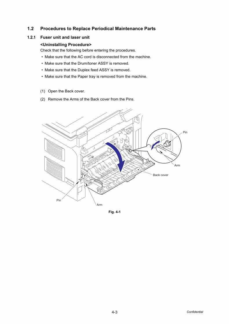
4-3 Confidential
1.2 Procedures to Replace Periodical Maintenance Parts
1.2.1 Fuser unit and laser unit<Uninstalling Procedure>Check that the following before entering the procedures.
• Make sure that the AC cord is disconnected from the machine.
• Make sure that the Drum/toner ASSY is removed.
• Make sure that the Duplex feed ASSY is removed.
• Make sure that the Paper tray is removed from the machine.
(1) Open the Back cover.
(2) Remove the Arms of the Back cover from the Pins.
Fig. 4-1
Back cover
Pin
Arm
ArmPin
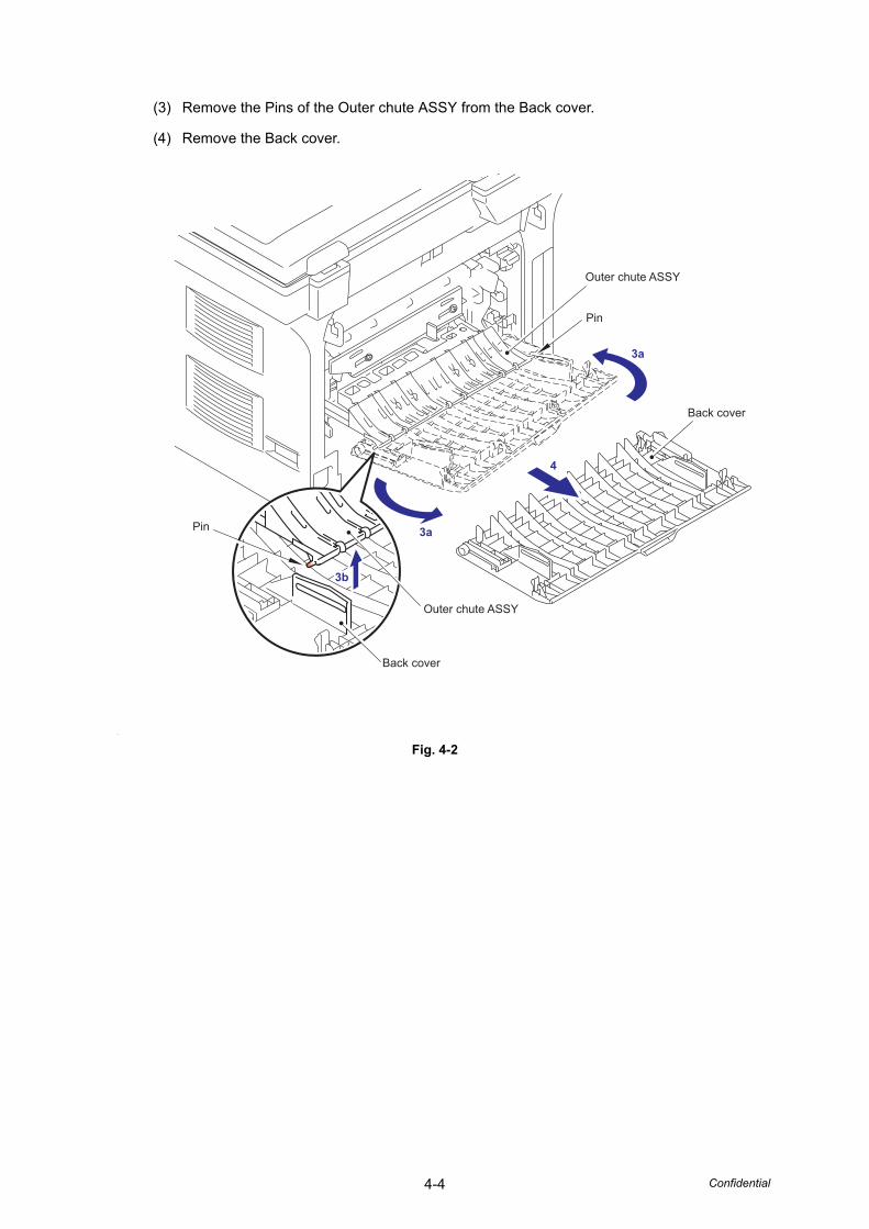
4-4 Confidential
(3) Remove the Pins of the Outer chute ASSY from the Back cover.
(4) Remove the Back cover.
Fig. 4-2
3a
3a
3b
4
Pin
Pin
Back cover
Back cover
Outer chute ASSY
Outer chute ASSY
3b
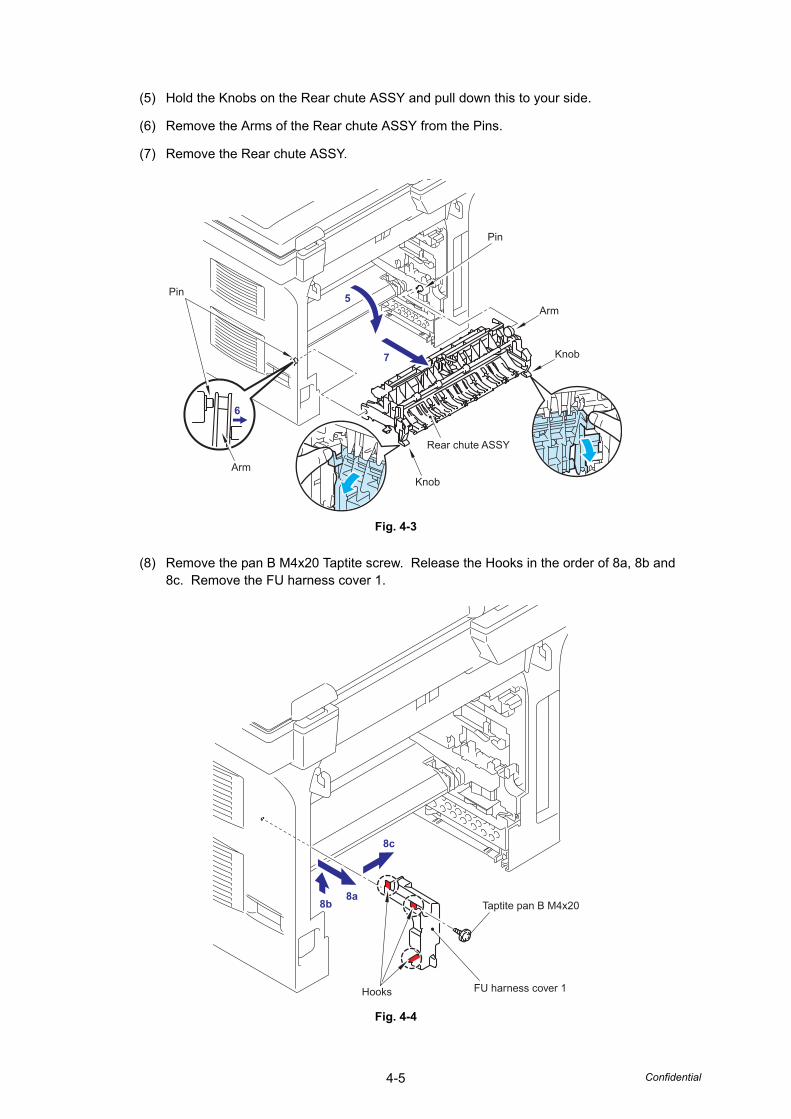
4-5 Confidential
(5) Hold the Knobs on the Rear chute ASSY and pull down this to your side.
(6) Remove the Arms of the Rear chute ASSY from the Pins.
(7) Remove the Rear chute ASSY.
Fig. 4-3
(8) Remove the pan B M4x20 Taptite screw. Release the Hooks in the order of 8a, 8b and 8c. Remove the FU harness cover 1.
Fig. 4-4
Pin
Pin
Knob
Arm
ArmKnob
Rear chute ASSY
5
6
7
Hooks FU harness cover 1
Taptite pan B M4x208b8a
8c
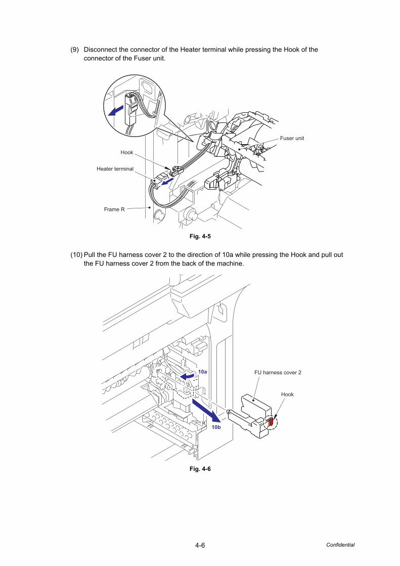
4-6 Confidential
(9) Disconnect the connector of the Heater terminal while pressing the Hook of the connector of the Fuser unit.
Fig. 4-5
(10) Pull the FU harness cover 2 to the direction of 10a while pressing the Hook and pull out the FU harness cover 2 from the back of the machine.
Fig. 4-6
Hook
Frame R
Heater terminal
Fuser unit
Hook
FU harness cover 23a
3b
10a
10b
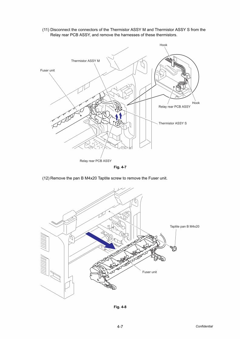
4-7 Confidential
(11) Disconnect the connectors of the Thermistor ASSY M and Thermistor ASSY S from the Relay rear PCB ASSY, and remove the harnesses of these thermistors.
Fig. 4-7
(12) Remove the pan B M4x20 Taptite screw to remove the Fuser unit.
Fig. 4-8
Thermistor ASSY S
Thermistor ASSY M
Fuser unit
Relay rear PCB ASSY
Relay rear PCB ASSYHook
Hook
Taptite pan B M4x20
Fuser unit
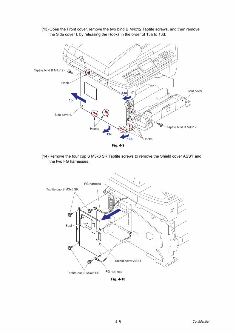
4-8 Confidential
(13) Open the Front cover, remove the two bind B M4x12 Taptite screws, and then remove the Side cover L by releasing the Hooks in the order of 13a to 13d.
Fig. 4-9
(14) Remove the four cup S M3x6 SR Taptite screws to remove the Shield cover ASSY and the two FG harnesses.
Fig. 4-10
Taptite bind B M4x12
Taptite bind B M4x12
Front cover
Hooks
Hooks
Hook
Side cover L
13a
13b
13d
13c
Taptite cup S M3x6 SR
Taptite cup S M3x6 SR FG harness
FG harness
Seal
Shield cover ASSY
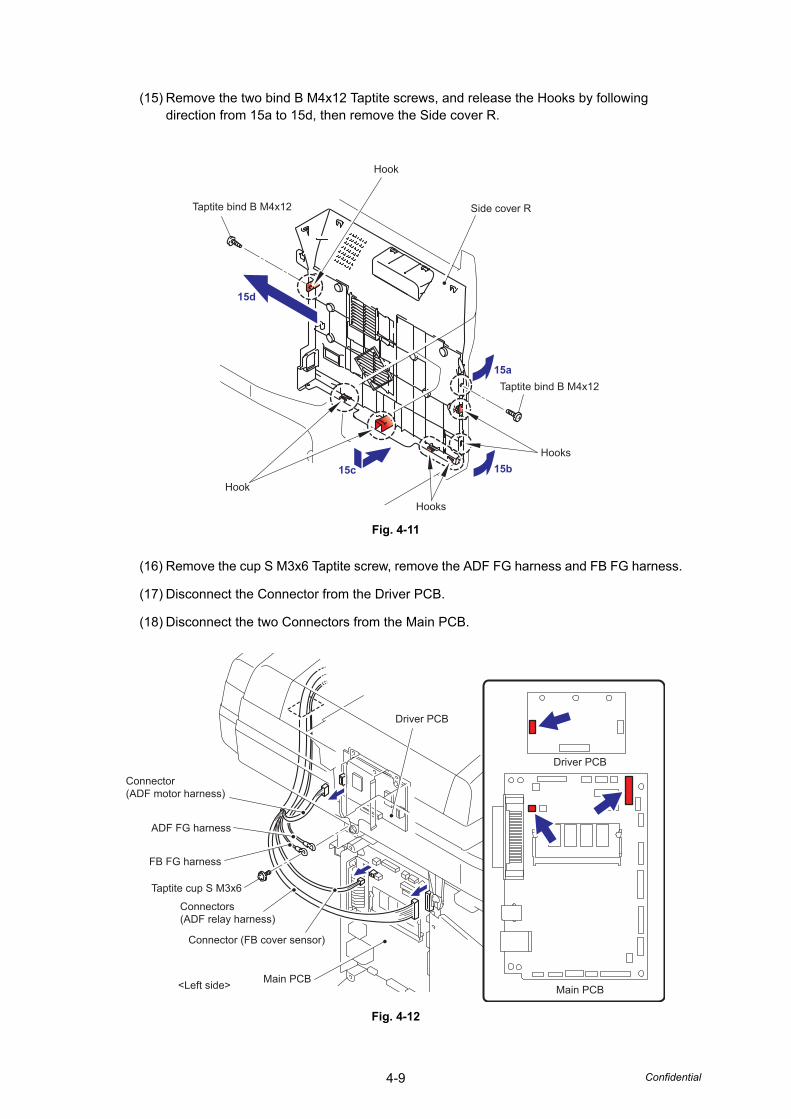
4-9 Confidential
(15) Remove the two bind B M4x12 Taptite screws, and release the Hooks by following direction from 15a to 15d, then remove the Side cover R.
Fig. 4-11
(16) Remove the cup S M3x6 Taptite screw, remove the ADF FG harness and FB FG harness.
(17) Disconnect the Connector from the Driver PCB.
(18) Disconnect the two Connectors from the Main PCB.
Fig. 4-12
Taptite bind B M4x12
Hook
Hooks
Hooks
Side cover R
Hook
Taptite bind B M4x12
15d
15c 15b
15a
Driver PCB
Main PCBMain PCB
Driver PCB
<Left side>
Connector(ADF motor harness)
Connectors(ADF relay harness)
Connector (FB cover sensor)
FB FG harness
Taptite cup S M3x6
ADF FG harness
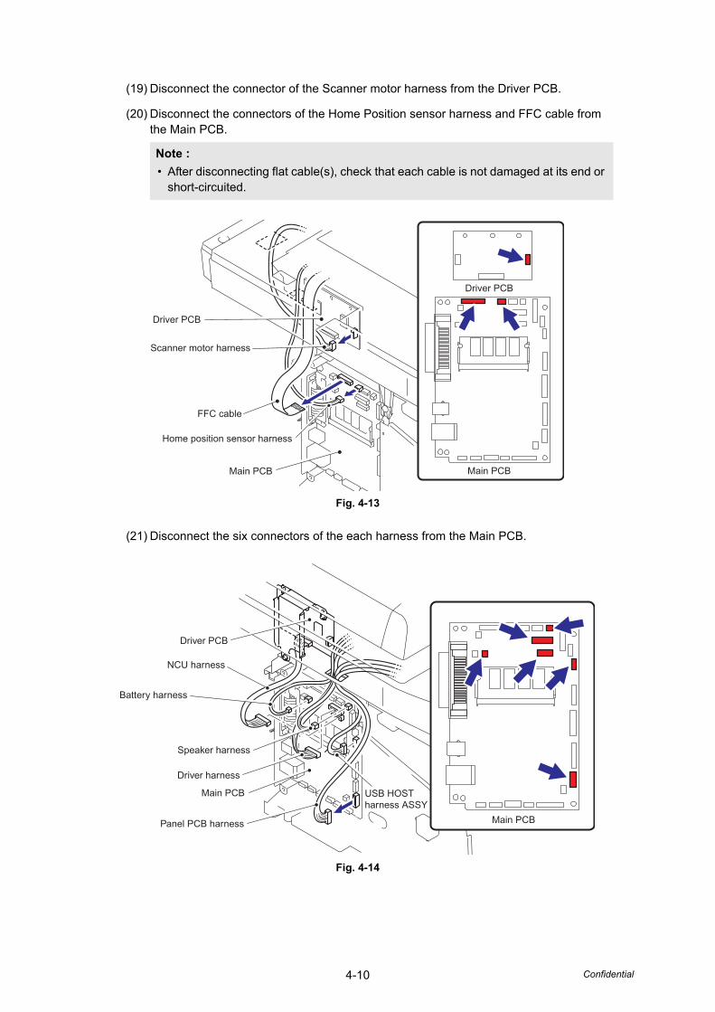
4-10 Confidential
(19) Disconnect the connector of the Scanner motor harness from the Driver PCB.
(20) Disconnect the connectors of the Home Position sensor harness and FFC cable from the Main PCB.
Fig. 4-13
(21) Disconnect the six connectors of the each harness from the Main PCB.
Fig. 4-14
Note :• After disconnecting flat cable(s), check that each cable is not damaged at its end or
short-circuited.
Driver PCB
Driver PCB
Scanner motor harness
FFC cable
Home position sensor harness
Main PCB Main PCB
Driver PCB
Battery harness
Speaker harness
NCU harness
USB HOSTharness ASSY
Driver harness
Panel PCB harness
Main PCB
Main PCB
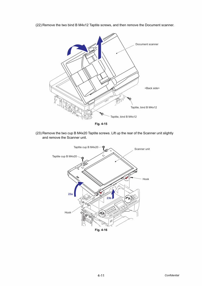
4-11 Confidential
(22) Remove the two bind B M4x12 Taptite screws, and then remove the Document scanner.
Fig. 4-15
(23) Remove the two cup B M4x20 Taptite screws. Lift up the rear of the Scanner unit slightly and remove the Scanner unit.
Fig. 4-16
Document scanner
Taptite, bind B M4x12
<Back side>
Taptite, bind B M4x12
Scanner unitTaptite cup B M4x20
Taptite cup B M4x20
23a
23b
Hook
Hook
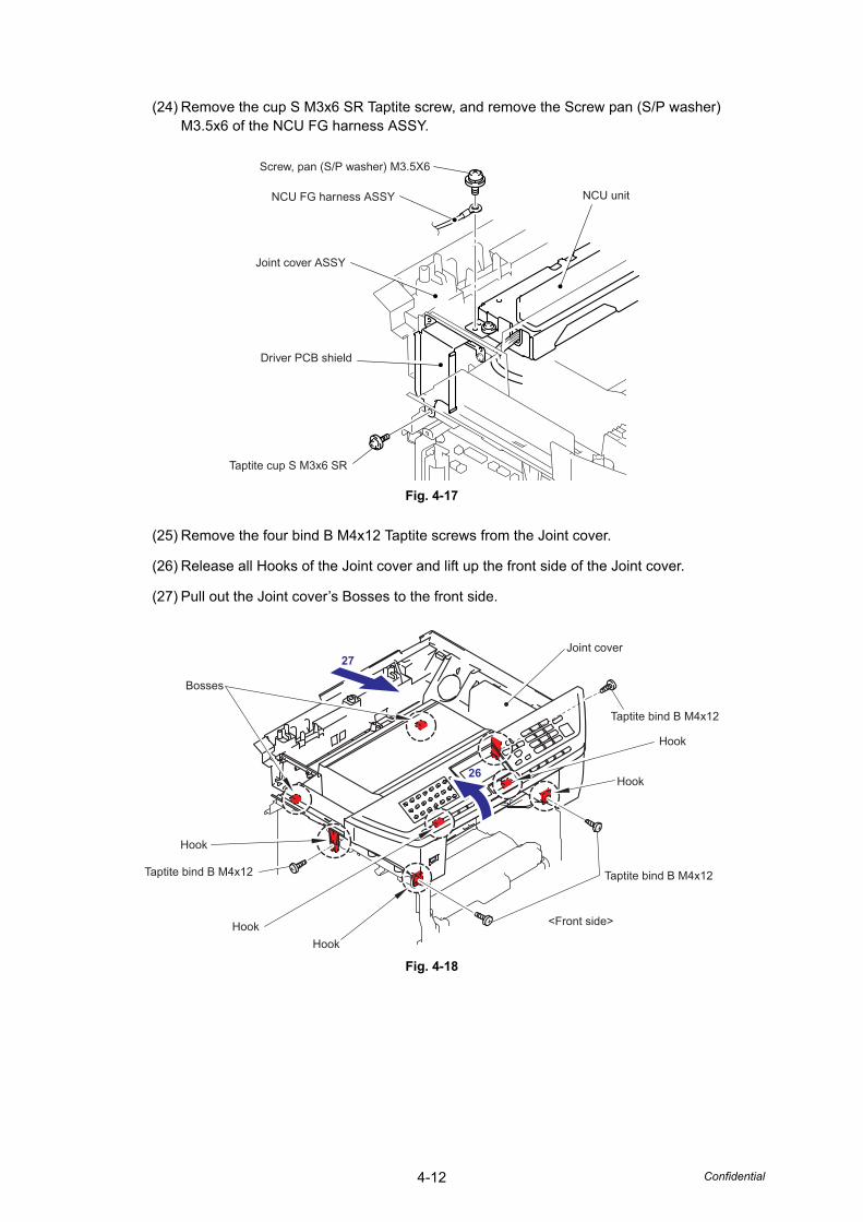
4-12 Confidential
(24) Remove the cup S M3x6 SR Taptite screw, and remove the Screw pan (S/P washer) M3.5x6 of the NCU FG harness ASSY.
Fig. 4-17
(25) Remove the four bind B M4x12 Taptite screws from the Joint cover.
(26) Release all Hooks of the Joint cover and lift up the front side of the Joint cover.
(27) Pull out the Joint cover’s Bosses to the front side.
Fig. 4-18
Screw, pan (S/P washer) M3.5X6
NCU FG harness ASSY NCU unit
Joint cover ASSY
Driver PCB shield
Taptite cup S M3x6 SR
5
Taptite bind B M4x12
Taptite bind B M4x12
Taptite bind B M4x12
<Front side>
Hook
Bosses
Hook
Hook
HookHook
Joint cover 27
26
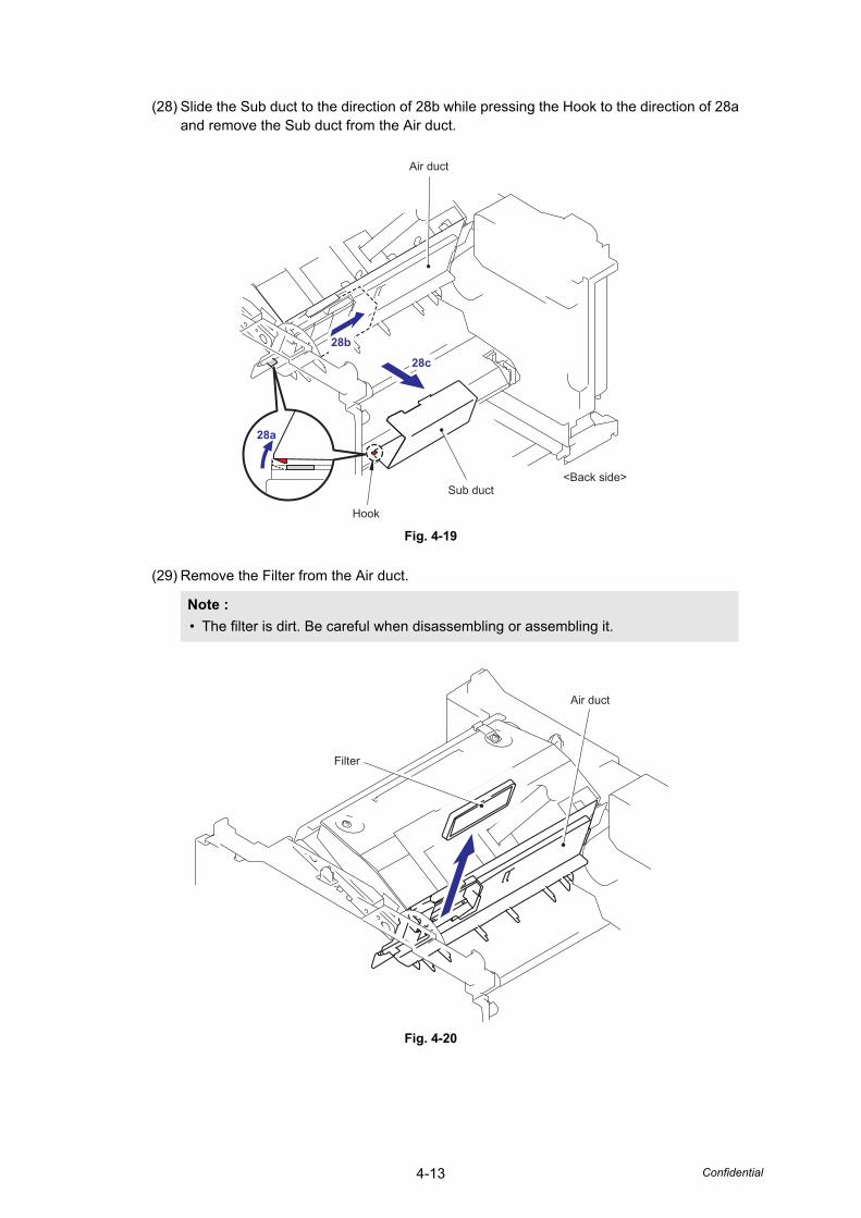
4-13 Confidential
(28) Slide the Sub duct to the direction of 28b while pressing the Hook to the direction of 28a and remove the Sub duct from the Air duct.
Fig. 4-19
(29) Remove the Filter from the Air duct.
Fig. 4-20
Note :• The filter is dirt. Be careful when disassembling or assembling it.
Air duct
Hook
Sub duct<Back side>
28a
28b
28c
Air duct
Filter
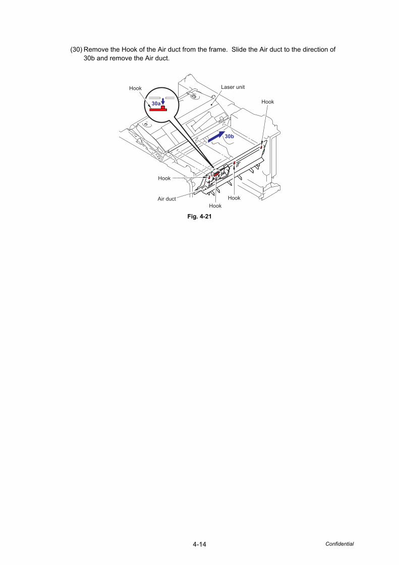
4-14 Confidential
(30) Remove the Hook of the Air duct from the frame. Slide the Air duct to the direction of 30b and remove the Air duct.
Fig. 4-21
Hook
Hook
HookHook
Hook
Laser unit
Air duct
30b
30a
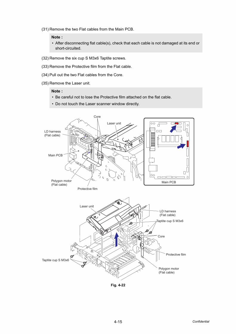
4-15 Confidential
(31) Remove the two Flat cables from the Main PCB.
(32) Remove the six cup S M3x6 Taptite screws.
(33) Remove the Protective film from the Flat cable.
(34) Pull out the two Flat cables from the Core.
(35) Remove the Laser unit.
Fig. 4-22
Note :• After disconnecting flat cable(s), check that each cable is not damaged at its end or
short-circuited.
Note :• Be careful not to lose the Protective film attached on the flat cable.
• Do not touch the Laser scanner window directly.
Taptite cup S M3x6
Polygon motor(Flat cable)
LD harness(Flat cable)
Core
Protective film
Laser unit
Taptite cup S M3x6
Core
LD harness(Flat cable)
Protective film
Main PCB
Main PCB
Polygon motor(Flat cable)
Laser unit
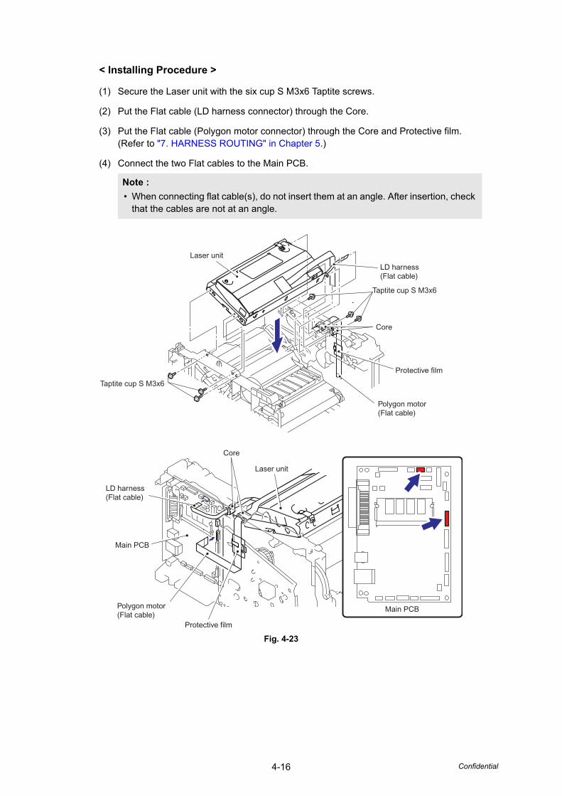
4-16 Confidential
< Installing Procedure >
(1) Secure the Laser unit with the six cup S M3x6 Taptite screws.
(2) Put the Flat cable (LD harness connector) through the Core.
(3) Put the Flat cable (Polygon motor connector) through the Core and Protective film.(Refer to "7. HARNESS ROUTING" in Chapter 5.)
(4) Connect the two Flat cables to the Main PCB.
Fig. 4-23
Note :• When connecting flat cable(s), do not insert them at an angle. After insertion, check
that the cables are not at an angle.
Taptite cup S M3x6
Polygon motor(Flat cable)
LD harness(Flat cable)
Core
Protective film
Laser unit
Taptite cup S M3x6
Core
LD harness(Flat cable)
Protective film
Main PCB
Main PCB
Polygon motor(Flat cable)
Laser unit
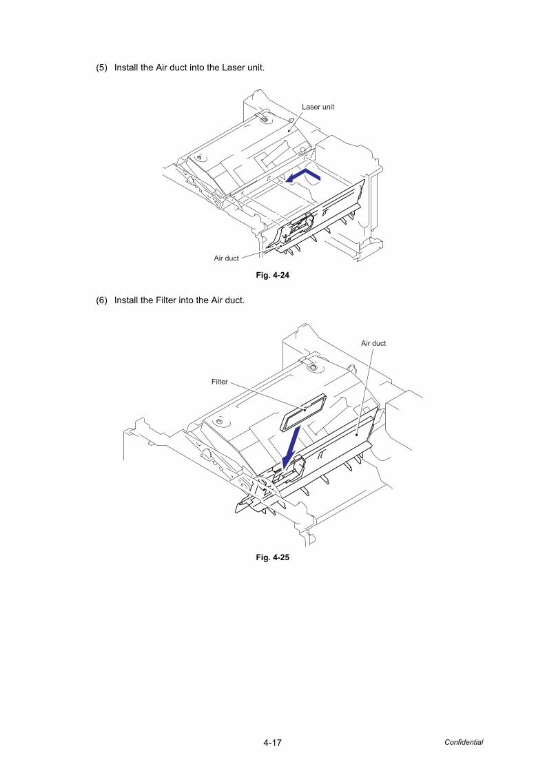
4-17 Confidential
(5) Install the Air duct into the Laser unit.
Fig. 4-24
(6) Install the Filter into the Air duct.
Fig. 4-25
Laser unit
Air duct
Air duct
Filter
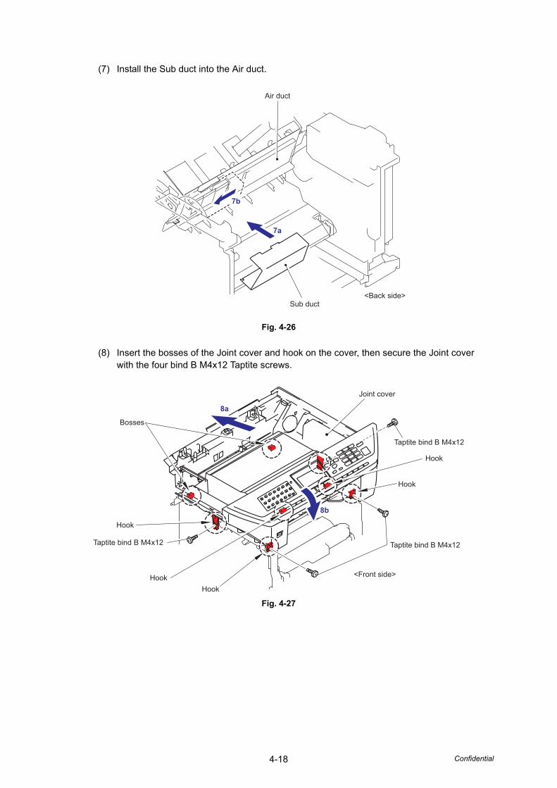
4-18 Confidential
(7) Install the Sub duct into the Air duct.
Fig. 4-26
(8) Insert the bosses of the Joint cover and hook on the cover, then secure the Joint cover with the four bind B M4x12 Taptite screws.
Fig. 4-27
Air duct
Sub duct<Back side>
7b
7a
5
8a
8b
Taptite bind B M4x12
Taptite bind B M4x12
Taptite bind B M4x12
<Front side>
Hook
Bosses
Hook
Hook
HookHook
Joint cover

4-19 Confidential
(9) Secure the Screw pan (S/P washer) M3.5x6 of the NCU FG harness ASSY.
(10) Secure the cup S M3x6 SR Taptite screw.
Fig. 4-28
(11) Catch the Hooks of the Scanner unit into the Joint cover and secure the Scanner unit with the two cup B M4x20 Taptite screws.
Fig. 4-29
Screw, pan (S/P washer) M3.5X6
NCU FG harness ASSY NCU unit
Joint cover ASSY
Driver PCB shield
Taptite cup S M3x6 SR
11b
11a
Scanner unitTaptite cup B M4x20
Taptite cup B M4x20
Hook
Hook
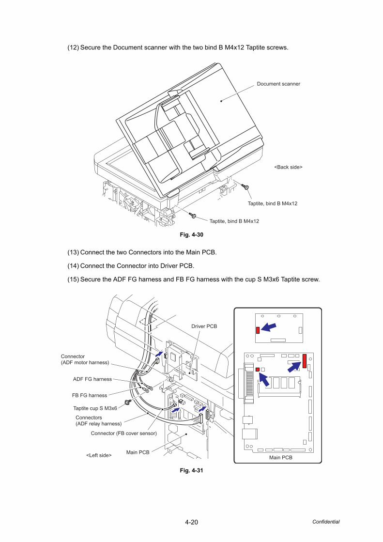
4-20 Confidential
(12) Secure the Document scanner with the two bind B M4x12 Taptite screws.
Fig. 4-30
(13) Connect the two Connectors into the Main PCB.
(14) Connect the Connector into Driver PCB.
(15) Secure the ADF FG harness and FB FG harness with the cup S M3x6 Taptite screw.
Fig. 4-31
Document scanner
Taptite, bind B M4x12
<Back side>
Taptite, bind B M4x12
Driver PCB
Main PCBMain PCB<Left side>
Connector(ADF motor harness)
Connectors(ADF relay harness)
Connector (FB cover sensor)
FB FG harness
Taptite cup S M3x6
ADF FG harness
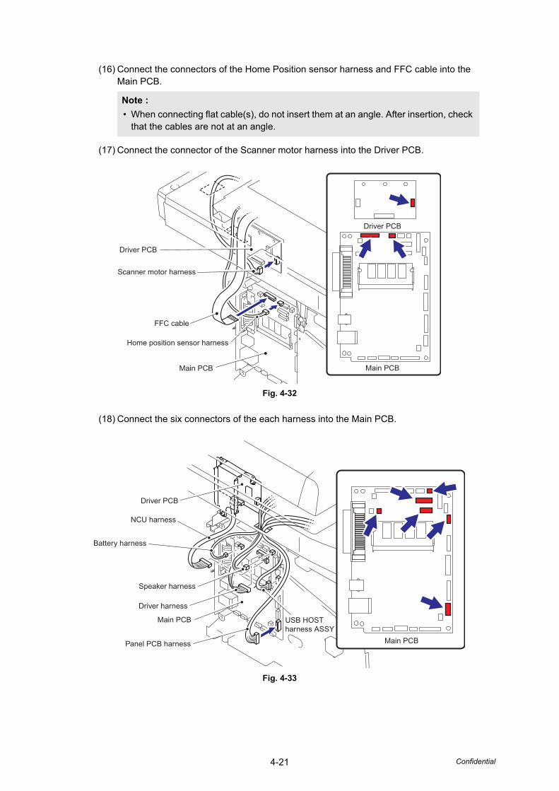
4-21 Confidential
(16) Connect the connectors of the Home Position sensor harness and FFC cable into the Main PCB.
(17) Connect the connector of the Scanner motor harness into the Driver PCB.
Fig. 4-32
(18) Connect the six connectors of the each harness into the Main PCB.
Fig. 4-33
Note :• When connecting flat cable(s), do not insert them at an angle. After insertion, check
that the cables are not at an angle.
Driver PCB
Driver PCB
Scanner motor harness
FFC cable
Home position sensor harness
Main PCB Main PCB
Driver PCB
Battery harness
Speaker harness
NCU harness
USB HOSTharness ASSY
Driver harness
Panel PCB harness
Main PCB
Main PCB
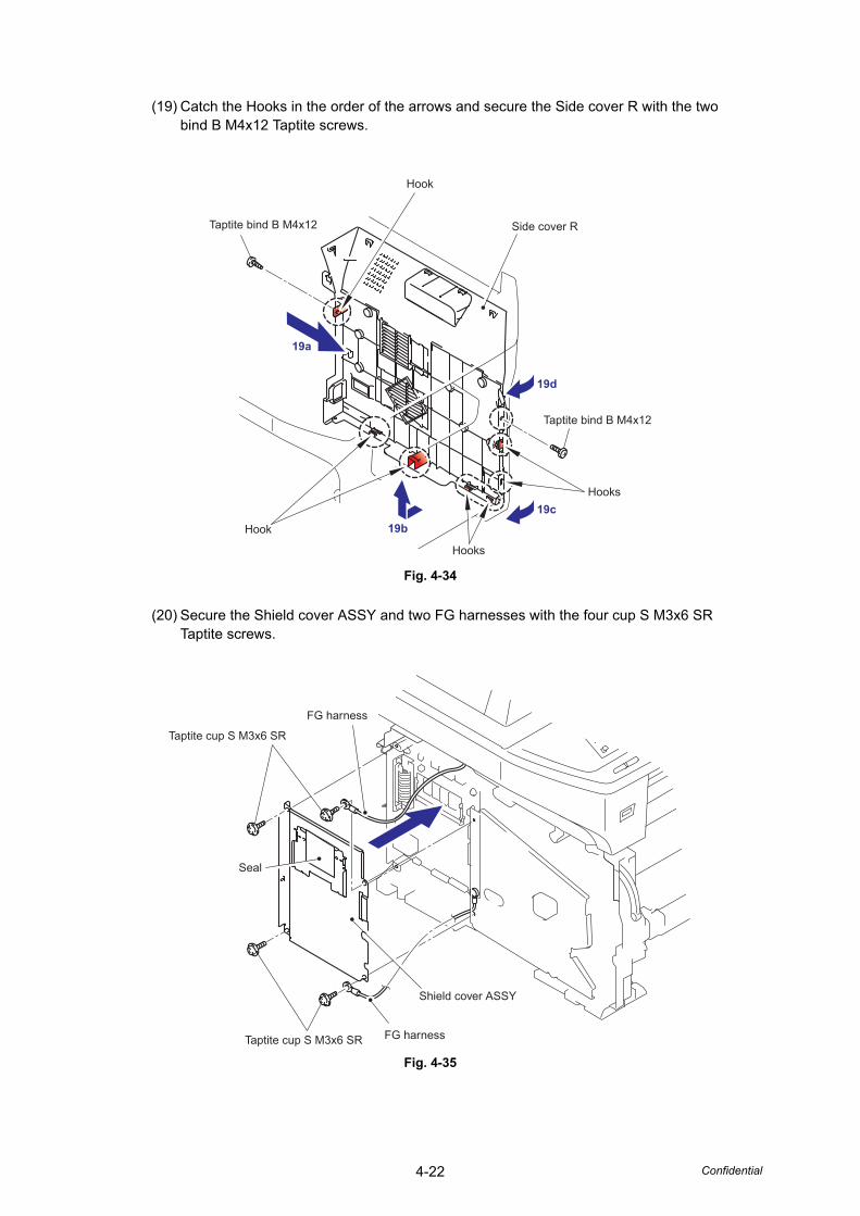
4-22 Confidential
(19) Catch the Hooks in the order of the arrows and secure the Side cover R with the two bind B M4x12 Taptite screws.
Fig. 4-34
(20) Secure the Shield cover ASSY and two FG harnesses with the four cup S M3x6 SR Taptite screws.
Fig. 4-35
19a
19b19c
19d
Taptite bind B M4x12
Hook
Hooks
Hooks
Side cover R
Hook
Taptite bind B M4x12
Taptite cup S M3x6 SR
Taptite cup S M3x6 SR FG harness
FG harness
Seal
Shield cover ASSY
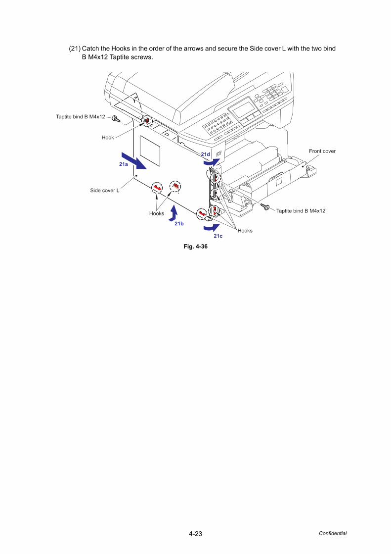
4-23 Confidential
(21) Catch the Hooks in the order of the arrows and secure the Side cover L with the two bind B M4x12 Taptite screws.
Fig. 4-36
21d
21c
21a
21b
Taptite bind B M4x12
Taptite bind B M4x12
Front cover
Hooks
Hooks
Hook
Side cover L
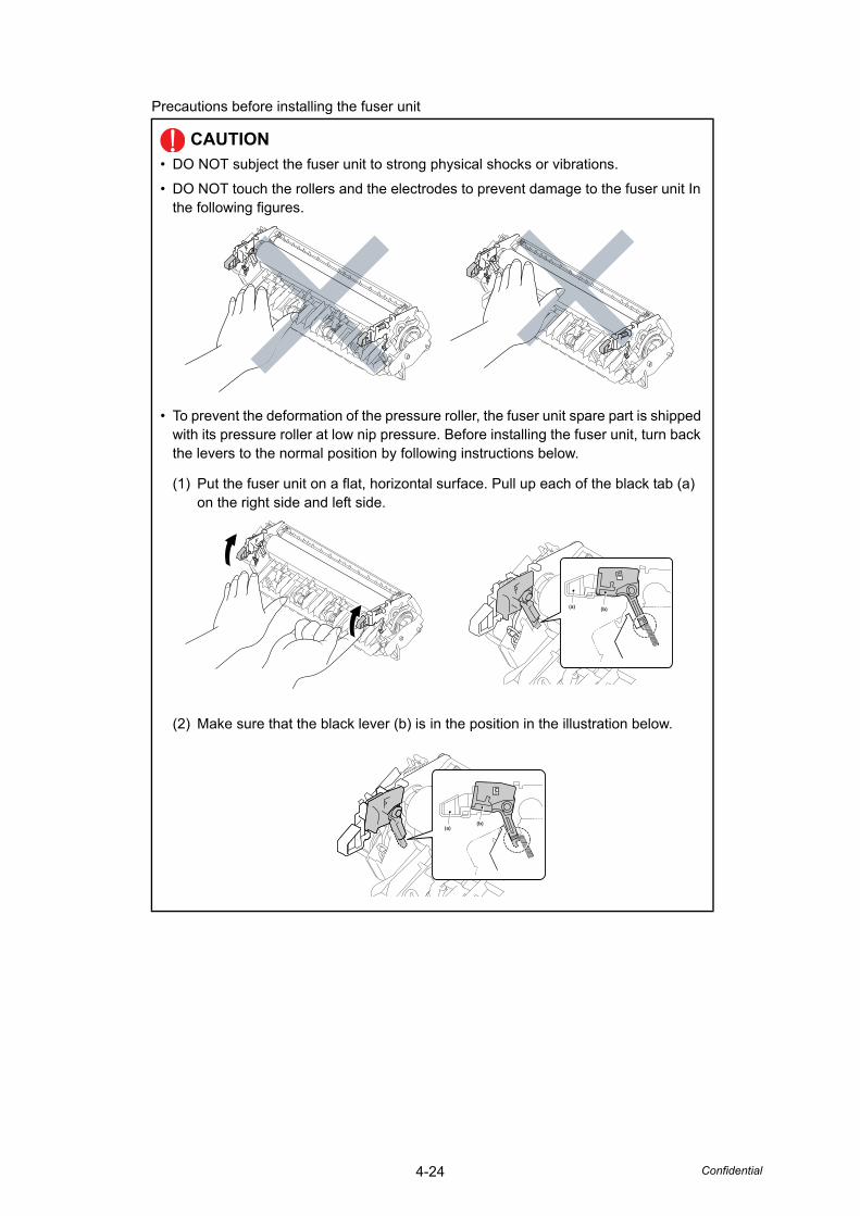
4-24 Confidential
Precautions before installing the fuser unit
CAUTION• DO NOT subject the fuser unit to strong physical shocks or vibrations.
• DO NOT touch the rollers and the electrodes to prevent damage to the fuser unit In the following figures.
• To prevent the deformation of the pressure roller, the fuser unit spare part is shipped with its pressure roller at low nip pressure. Before installing the fuser unit, turn back the levers to the normal position by following instructions below.
(1) Put the fuser unit on a flat, horizontal surface. Pull up each of the black tab (a) on the right side and left side.
(2) Make sure that the black lever (b) is in the position in the illustration below.
(a) (b)
(a)(b)
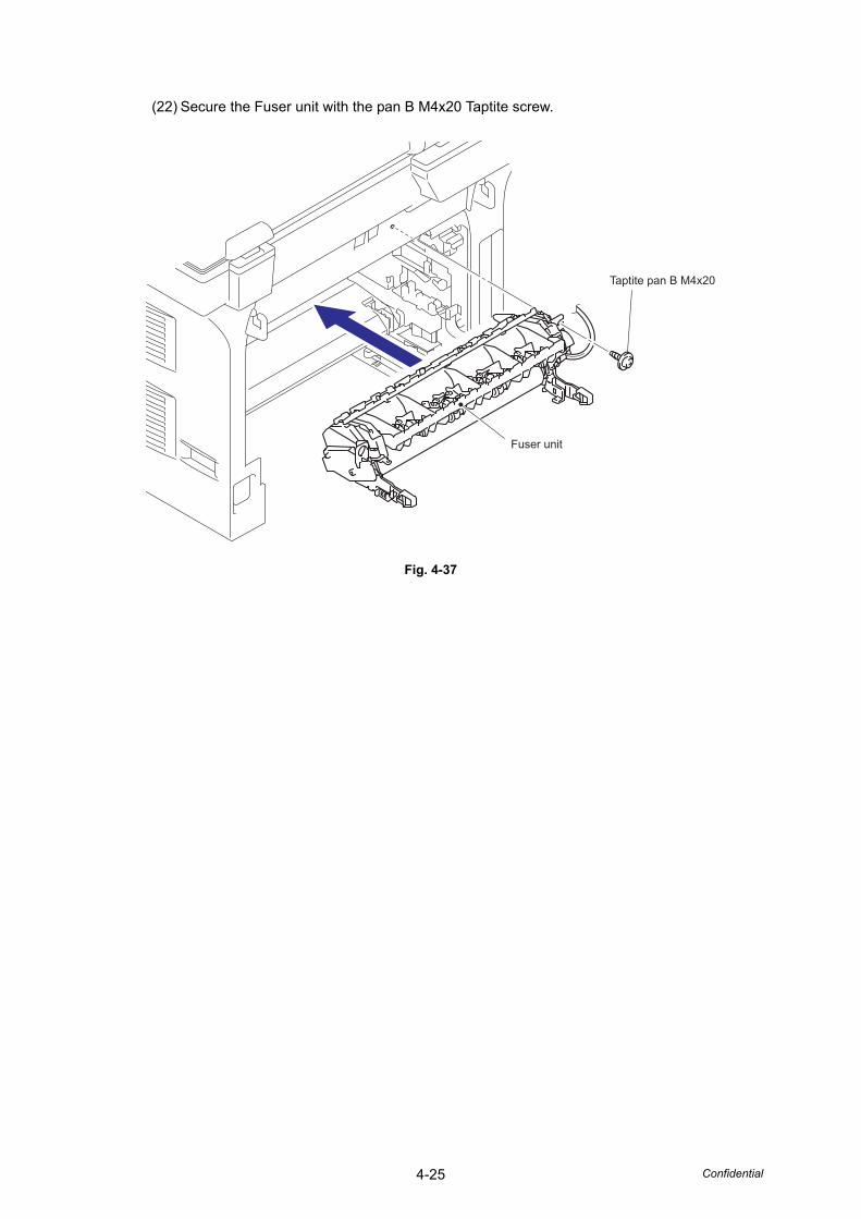
4-25 Confidential
(22) Secure the Fuser unit with the pan B M4x20 Taptite screw.
Fig. 4-37
Taptite pan B M4x20
Fuser unit
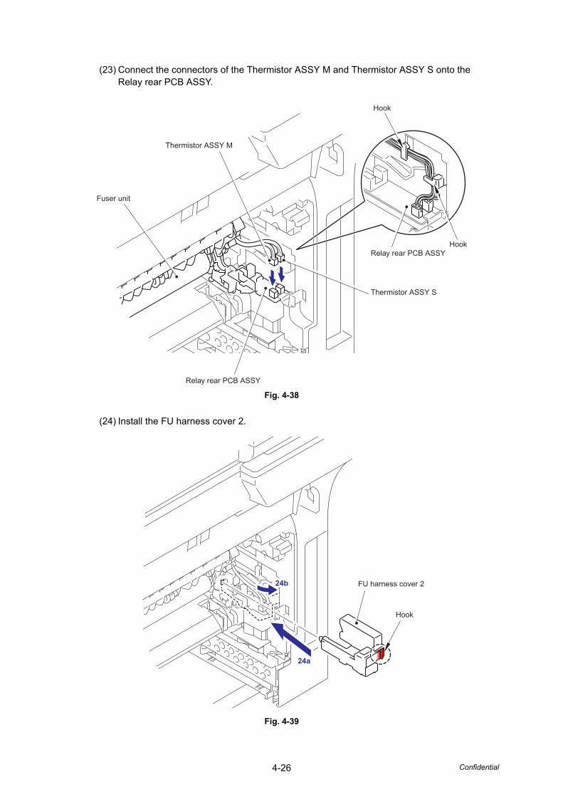
4-26 Confidential
(23) Connect the connectors of the Thermistor ASSY M and Thermistor ASSY S onto the Relay rear PCB ASSY.
Fig. 4-38
(24) Install the FU harness cover 2.
Fig. 4-39
Thermistor ASSY S
Thermistor ASSY M
Fuser unit
Relay rear PCB ASSY
Relay rear PCB ASSYHook
Hook
3a
3b
24b
24a
Hook
FU harness cover 2
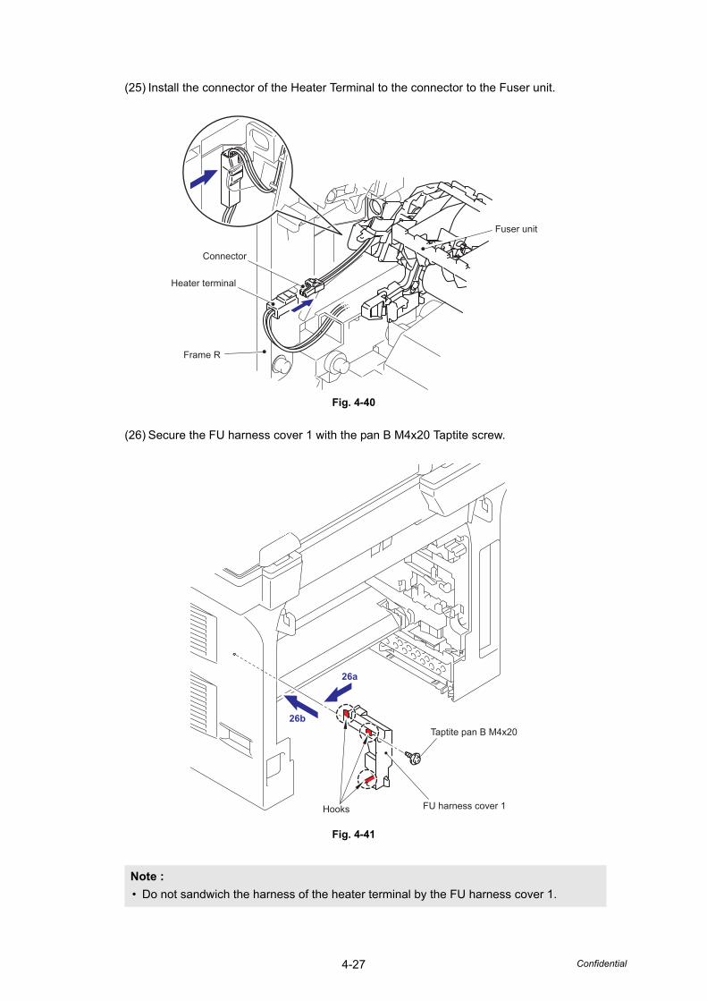
4-27 Confidential
(25) Install the connector of the Heater Terminal to the connector to the Fuser unit.
Fig. 4-40
(26) Secure the FU harness cover 1 with the pan B M4x20 Taptite screw.
Fig. 4-41
Note :• Do not sandwich the harness of the heater terminal by the FU harness cover 1.
Connector
Frame R
Heater terminal
Fuser unit
26b
26a
Hooks FU harness cover 1
Taptite pan B M4x20
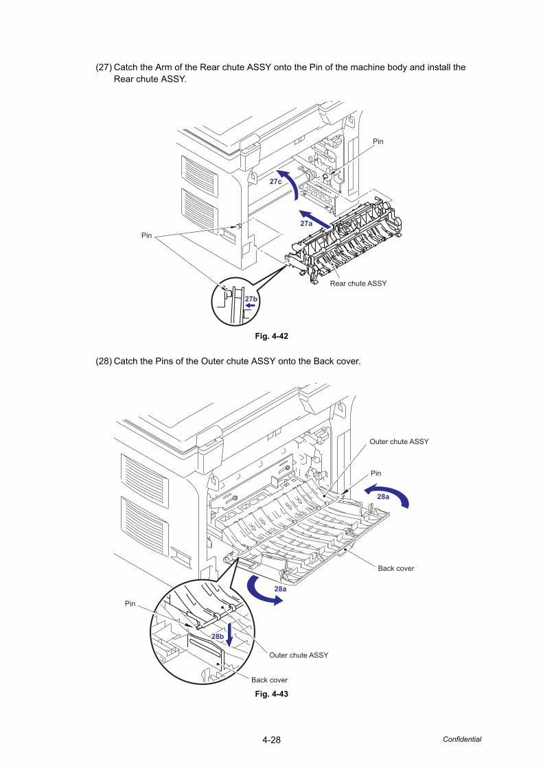
4-28 Confidential
(27) Catch the Arm of the Rear chute ASSY onto the Pin of the machine body and install the Rear chute ASSY.
Fig. 4-42
(28) Catch the Pins of the Outer chute ASSY onto the Back cover.
Fig. 4-43
27c
27b
27aPin
Pin
Rear chute ASSY
28a
28a
Pin
Pin
Back cover
Back cover
Outer chute ASSY
Outer chute ASSY
29b28b
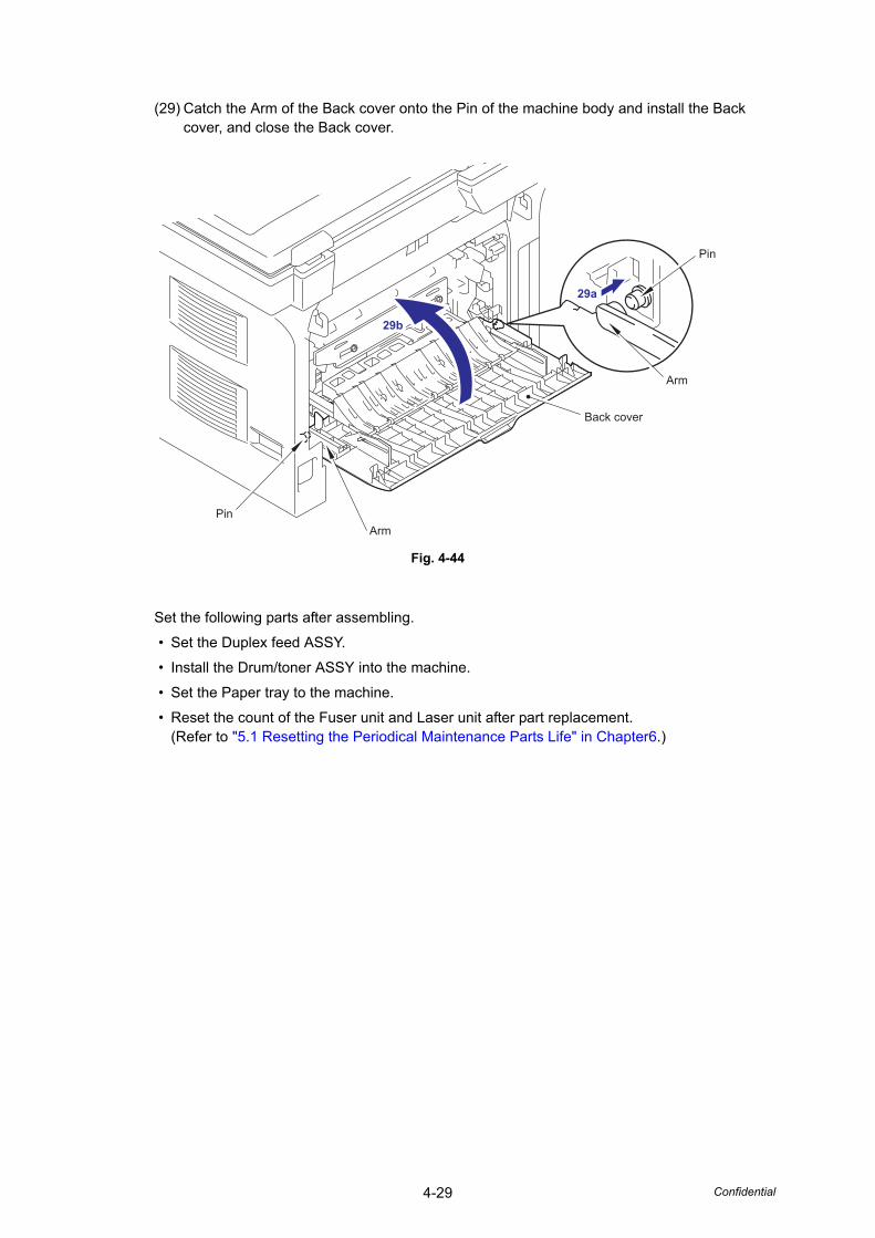
4-29 Confidential
(29) Catch the Arm of the Back cover onto the Pin of the machine body and install the Back cover, and close the Back cover.
Fig. 4-44
Set the following parts after assembling.
• Set the Duplex feed ASSY.
• Install the Drum/toner ASSY into the machine.
• Set the Paper tray to the machine.
• Reset the count of the Fuser unit and Laser unit after part replacement.(Refer to "5.1 Resetting the Periodical Maintenance Parts Life" in Chapter6.)
29b
29a
Back cover
Pin
Arm
ArmPin
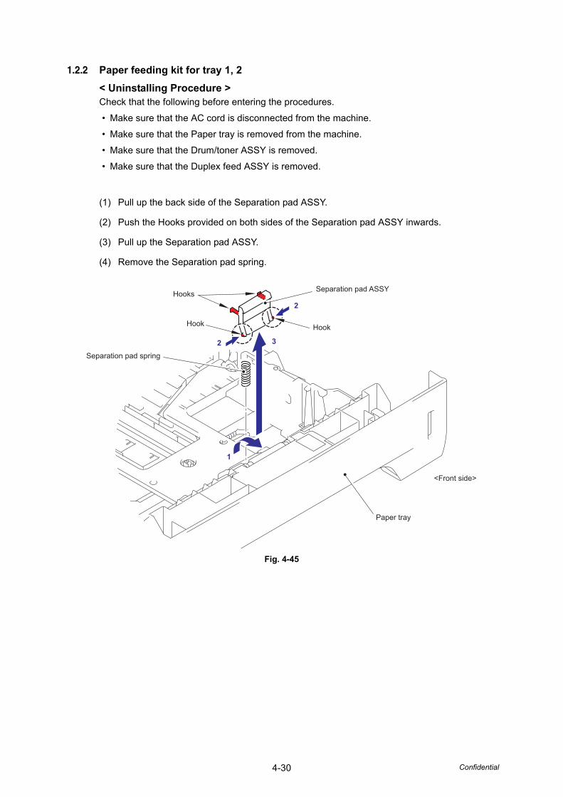
4-30 Confidential
1.2.2 Paper feeding kit for tray 1, 2< Uninstalling Procedure >Check that the following before entering the procedures.
• Make sure that the AC cord is disconnected from the machine.
• Make sure that the Paper tray is removed from the machine.
• Make sure that the Drum/toner ASSY is removed.
• Make sure that the Duplex feed ASSY is removed.
(1) Pull up the back side of the Separation pad ASSY.
(2) Push the Hooks provided on both sides of the Separation pad ASSY inwards.
(3) Pull up the Separation pad ASSY.
(4) Remove the Separation pad spring.
Fig. 4-45
Separation pad ASSYHooks
Hook
Separation pad spring
Hook
Paper tray
<Front side>
2
3
1
2
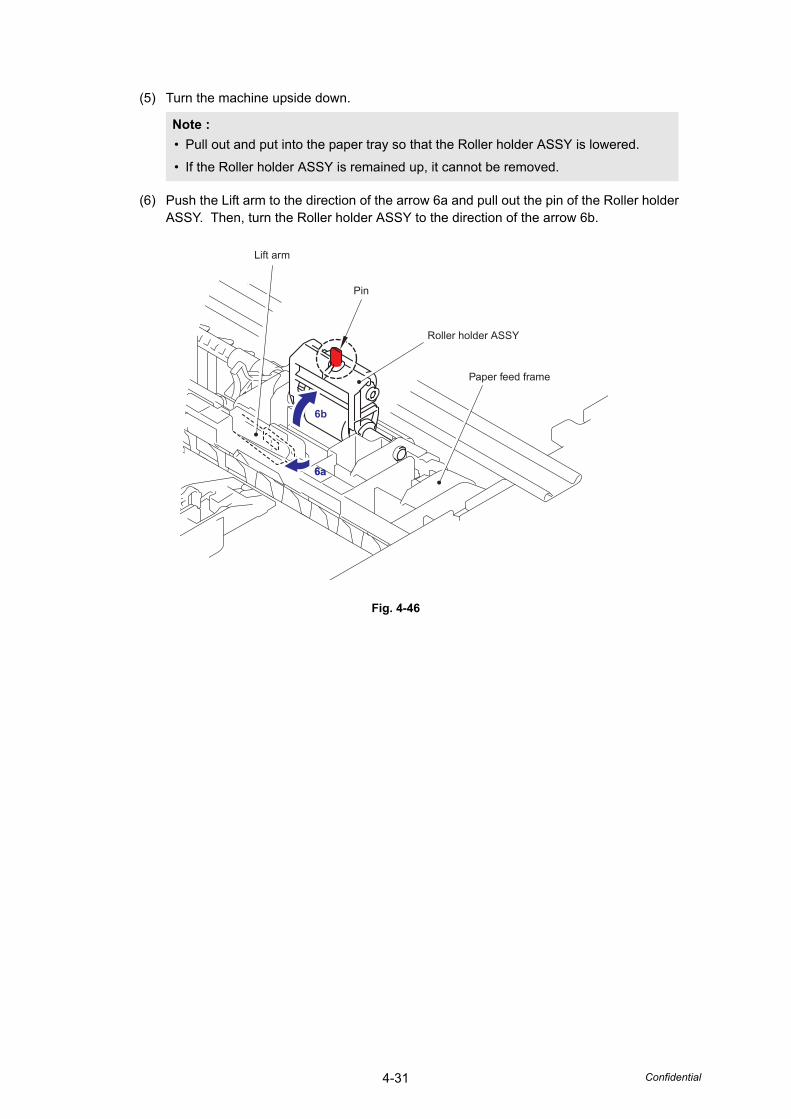
4-31 Confidential
(5) Turn the machine upside down.
(6) Push the Lift arm to the direction of the arrow 6a and pull out the pin of the Roller holder ASSY. Then, turn the Roller holder ASSY to the direction of the arrow 6b.
Fig. 4-46
Note :• Pull out and put into the paper tray so that the Roller holder ASSY is lowered.
• If the Roller holder ASSY is remained up, it cannot be removed.
Lift arm
Pin
Roller holder ASSY
6b
Paper feed frame
6a6a
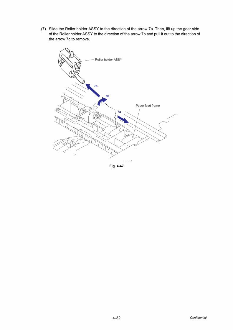
4-32 Confidential
(7) Slide the Roller holder ASSY to the direction of the arrow 7a. Then, lift up the gear side of the Roller holder ASSY to the direction of the arrow 7b and pull it out to the direction of the arrow 7c to remove.
Fig. 4-47
7c
7b
7a
Roller holder ASSY
Paper feed frame
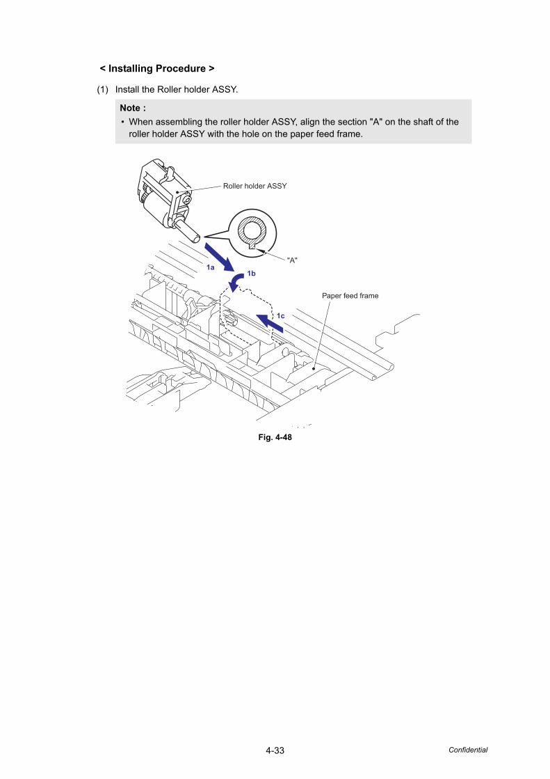
4-33 Confidential
< Installing Procedure >
(1) Install the Roller holder ASSY.
Fig. 4-48
Note :• When assembling the roller holder ASSY, align the section "A" on the shaft of the
roller holder ASSY with the hole on the paper feed frame.
1c
1b1a
Roller holder ASSY
"A"
Paper feed frame
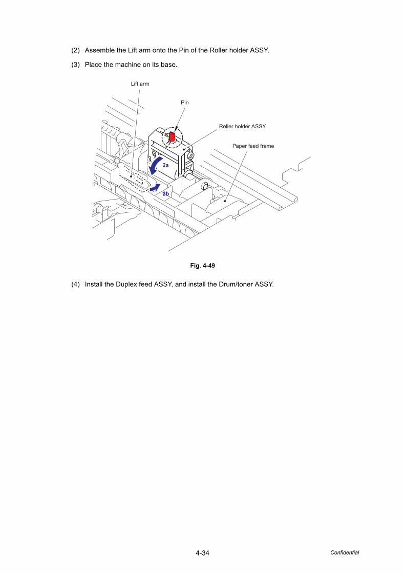
4-34 Confidential
(2) Assemble the Lift arm onto the Pin of the Roller holder ASSY.
(3) Place the machine on its base.
Fig. 4-49
(4) Install the Duplex feed ASSY, and install the Drum/toner ASSY.
2a
Lift arm
Pin
Roller holder ASSY
Paper feed frame
2b2b
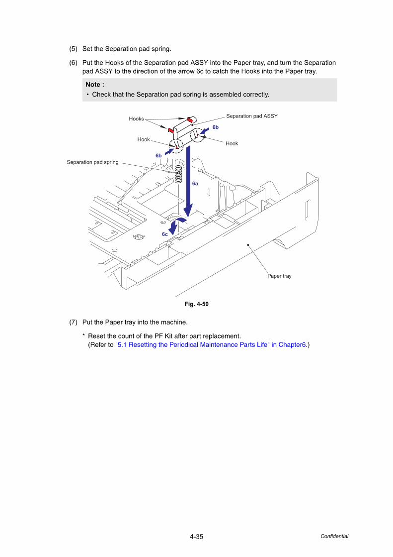
4-35 Confidential
(5) Set the Separation pad spring.
(6) Put the Hooks of the Separation pad ASSY into the Paper tray, and turn the Separation pad ASSY to the direction of the arrow 6c to catch the Hooks into the Paper tray.
Fig. 4-50
(7) Put the Paper tray into the machine.
* Reset the count of the PF Kit after part replacement.(Refer to "5.1 Resetting the Periodical Maintenance Parts Life" in Chapter6.)
Note :• Check that the Separation pad spring is assembled correctly.
6b
6a
6c
6b
Hooks
HookHook
Separation pad ASSY
Separation pad spring
Paper tray
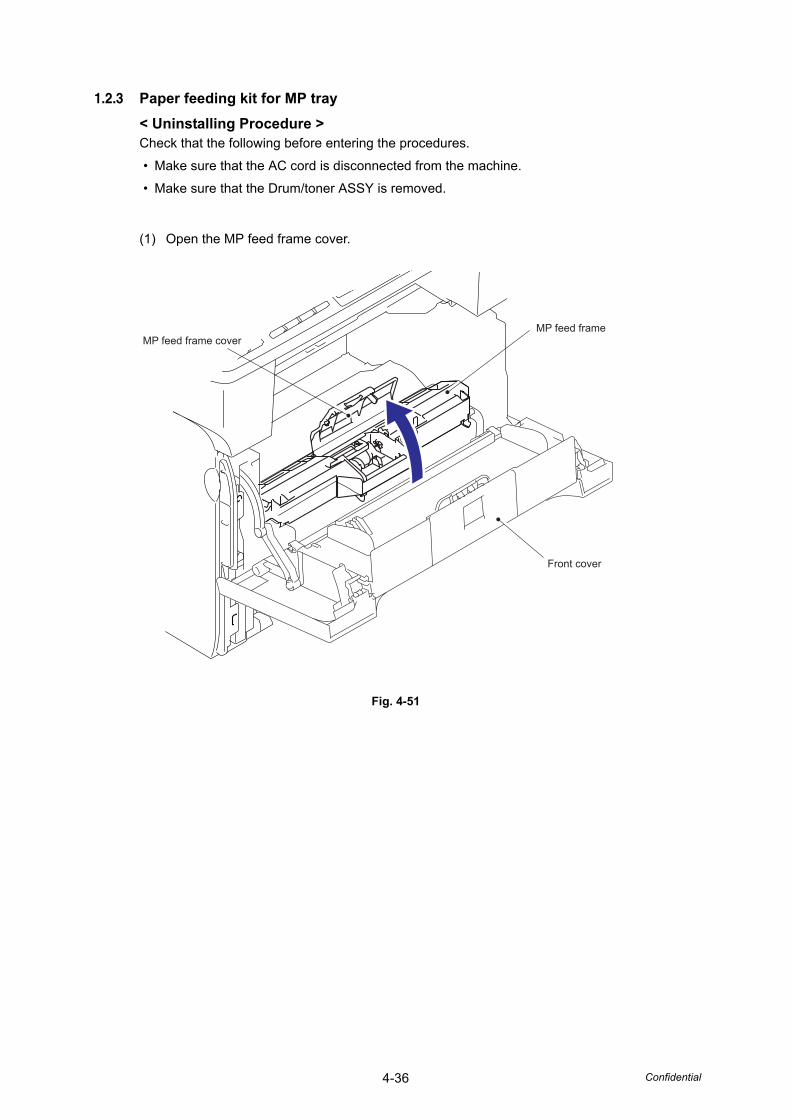
4-36 Confidential
1.2.3 Paper feeding kit for MP tray< Uninstalling Procedure >Check that the following before entering the procedures.
• Make sure that the AC cord is disconnected from the machine.
• Make sure that the Drum/toner ASSY is removed.
(1) Open the MP feed frame cover.
Fig. 4-51
MP feed frameMP feed frame cover
Front cover
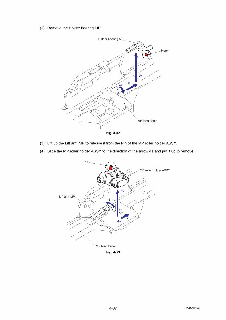
4-37 Confidential
(2) Remove the Holder bearing MP.
Fig. 4-52
(3) Lift up the Lift arm MP to release it from the Pin of the MP roller holder ASSY.
(4) Slide the MP roller holder ASSY to the direction of the arrow 4a and put it up to remove.
Fig. 4-53
2a 2b
2c
MP feed frame
Hook
Holder bearing MP
4a
3
4b
Pin
Lift arm MP
MP feed frame
MP roller holder ASSY
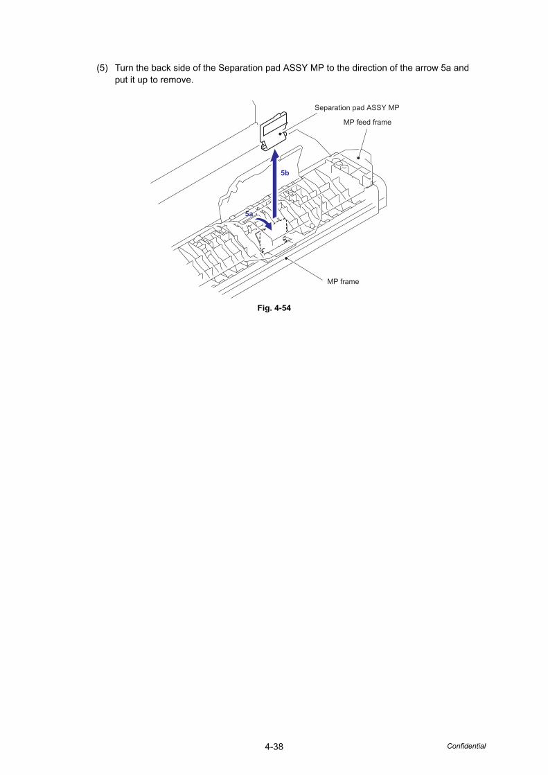
4-38 Confidential
(5) Turn the back side of the Separation pad ASSY MP to the direction of the arrow 5a and put it up to remove.
Fig. 4-54
5b
Separation pad ASSY MP
MP feed frame
MP frame
5a5a
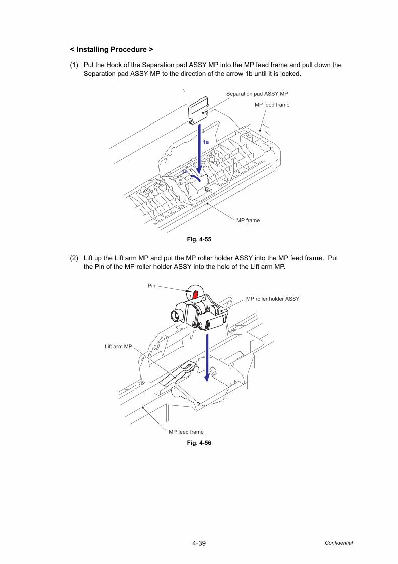
4-39 Confidential
< Installing Procedure >
(1) Put the Hook of the Separation pad ASSY MP into the MP feed frame and pull down the Separation pad ASSY MP to the direction of the arrow 1b until it is locked.
Fig. 4-55
(2) Lift up the Lift arm MP and put the MP roller holder ASSY into the MP feed frame. Put the Pin of the MP roller holder ASSY into the hole of the Lift arm MP.
Fig. 4-56
1a
MP feed frame
MP frame
Separation pad ASSY MP
1b1b
MP feed frame
Lift arm MP
MP roller holder ASSY
Pin
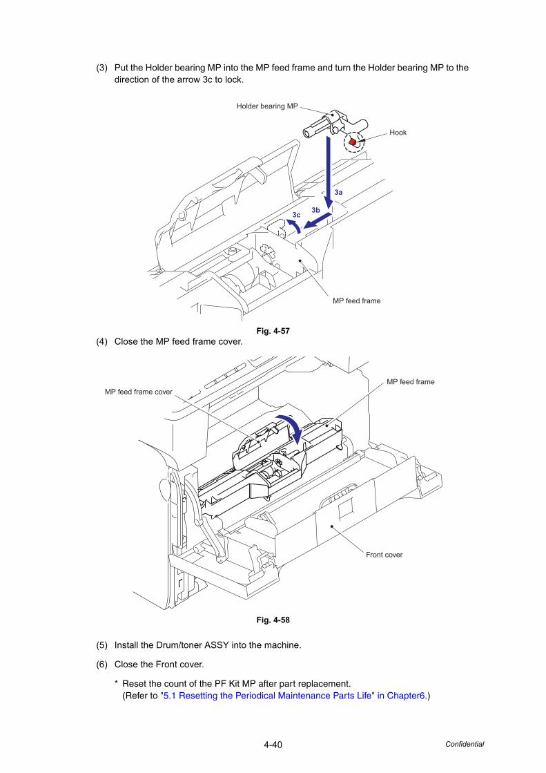
4-40 Confidential
(3) Put the Holder bearing MP into the MP feed frame and turn the Holder bearing MP to the direction of the arrow 3c to lock.
Fig. 4-57(4) Close the MP feed frame cover.
Fig. 4-58
(5) Install the Drum/toner ASSY into the machine.
(6) Close the Front cover.
* Reset the count of the PF Kit MP after part replacement.(Refer to "5.1 Resetting the Periodical Maintenance Parts Life" in Chapter6.)
3a
3b3c
MP feed frame
Holder bearing MP
Hook
Front cover
MP feed frameMP feed frame cover

CHAPTER 5DISASSEMBLY/REASSEMBLY
Confidential
CHAPTER 5 DISASSEMBLY/REASSEMBLY
This chapter details procedures for disassembling and reassembling the machine together with related notes. The disassembly order flow provided enables you to see at a glance the quickest way to get to component(s) involved.
At the start of a disassembly job, you check the disassembly order flow that guides you through a shortcut to the object components.
This chapter also covers screw tightening torques and lubrication points to which the specified lubricants should be applied during reassembly jobs.
CONTENTS1. SAFETY PRECAUTIONS .............................................................................................5-1
2. TRANSFERRING RECEIVED FAX DATA ....................................................................5-2
3. SCREW TORQUE LIST ................................................................................................5-4
4. LUBRICATION ..............................................................................................................5-7
6. GEAR LAYOUT DRAWING ..........................................................................................5-9
7. HARNESS ROUTING..................................................................................................5-12
8. DISASSEMBLY FLOW CHART..................................................................................5-29
9. DISASSEMBLY PROCEDURE ...................................................................................5-31
9.1 Paper Tray .........................................................................................................5-32
9.2 Back Cover ........................................................................................................5-35
9.3 Rear Chute ASSY ..............................................................................................5-37
9.4 Fuser Unit ..........................................................................................................5-39
9.5 Tray MP ASSY...................................................................................................5-43
9.6 MP Tray Cover ASSY / Process Cover ASSY / Emblem cover .........................5-44
9.7 Access Cover / Side Cover L .............................................................................5-48
9.8 ADF Unit ............................................................................................................5-49
9.8.1 ADF Unit......................................................................................................5-49
9.8.2 Hinge Arm R................................................................................................5-51
9.8.3 Hinge Base R ..............................................................................................5-51
9.8.4 Hinge ASSY L .............................................................................................5-52
9.8.5 ADF Cover ASSY........................................................................................5-52
9.8.6 ADF Side Cover F .......................................................................................5-53
9.8.7 ADF Side Cover R.......................................................................................5-53
9.8.8 ADF Chute ASSY........................................................................................5-54
9.8.9 Sub Chute ASSY / SX Chute ......................................................................5-56
9.8.10 Exit Chute Cover ASSY...............................................................................5-56
9.8.11 Earth Spring.................................................................................................5-57
9.8.12 PF Roller Holder ASSY ...............................................................................5-58
9.8.13 LF Roller 1 ASSY ........................................................................................5-59
9.8.14 Switch Back Roller ASSY............................................................................5-60
Confidential
9.8.15 ADF Motor ...................................................................................................5-62
9.8.16 Switch Back Solenoid ASSY .......................................................................5-63
9.8.17 PF Solenoid ASSY ......................................................................................5-63
9.8.18 ADF Relay PCB...........................................................................................5-64
9.8.19 Paper Feed Chute ASSY ............................................................................5-65
9.8.20 Document Front Actuator 1 / Document Front Sensor 1 .............................5-66
9.8.21 Document Front Actuator 2 / Document Front Sensor 2 .............................5-67
9.8.22 ADF Film / Spring Plate ADF Front A ASSY /Separation Rubber / Rubber Holder / Separation Spring ............................5-68
9.8.23 Pressure Roller / LF Spring .........................................................................5-69
9.8.24 LF Roller 2 ASSY ........................................................................................5-70
9.8.25 Document Exit Roller ASSY ........................................................................5-71
9.8.26 LF Roller 3 ASSY ........................................................................................5-72
9.8.27 LF Roller 4 ASSY ........................................................................................5-73
9.8.28 Flap A ASSY / Flap A ..................................................................................5-74
9.8.29 Document Hold / Document Hold Spring.....................................................5-75
9.8.30 Upper Main Chute ASSY / Lower Main Chute ASSY..................................5-75
9.8.31 Document Rear Actuator / Document Rear Sensor ....................................5-77
9.8.32 Flap B ..........................................................................................................5-78
9.8.33 Actuator Switch Back / Switch Back Sensor ...............................................5-79
9.8.34 Document Eject Tray ...................................................................................5-80
9.8.35 Document Cover Sensor .............................................................................5-80
9.8.36 Eject Roller B4.............................................................................................5-81
9.8.37 Pressure Roller............................................................................................5-82
9.9 Panel Cover ASSY.............................................................................................5-83
9.9.1 Panel Cover ASSY ......................................................................................5-839.10 Scanner Unit ASSY............................................................................................5-84
9.10.1 Scanner Unit ASSY.....................................................................................5-849.10.2 Top Cover ASSY .........................................................................................5-859.10.3 Lock Lever B / Lock Lever ASSY ................................................................5-869.10.4 CCD Module................................................................................................5-869.10.5 FFC Cable ASSY ........................................................................................5-889.10.6 Scanner Motor FB .......................................................................................5-899.10.7 Pulley ASSY................................................................................................5-909.10.8 Home Position Sensor.................................................................................5-90
9.11 Panel Unit ..........................................................................................................5-91
9.11.1 Panel Unit....................................................................................................5-919.11.2 Panel PCB ASSY ........................................................................................5-939.11.3 Printed Rubber Key .....................................................................................5-959.11.4 LCD Cover / Backlight Module / LCD ..........................................................5-96
Confidential
9.12 NCU PCB ASSY ................................................................................................5-97
9.13 Speaker ASSY .................................................................................................5-100
9.14 Driver PCB .......................................................................................................5-101
9.15 USB HOST PCB ASSY....................................................................................5-103
9.16 Side Cover R....................................................................................................5-105
9.17 Battery..............................................................................................................5-106
9.18 Joint Cover ASSY ............................................................................................5-107
9.19 Main PCB.........................................................................................................5-108
9.20 Gear Plate Calking ASSY / Develop Joint / Main Motor ASSY........................ 5-110
9.21 Main Shield Plate ASSY .................................................................................. 5-112
9.22 Relay Rear PCB ASSY / tray 2 Connector ...................................................... 5-1159.23 Relay Front PCB ASSY ................................................................................... 5-1179.24 Drive Release Link........................................................................................... 5-1189.25 MP Solenoid ASSY .......................................................................................... 5-1199.26 Tray 1 Solenoid ASSY .....................................................................................5-1209.27 Toner Sensor PCB ASSY.................................................................................5-1219.28 Register Solenoid ASSY ..................................................................................5-1229.29 Ejector Solenoid ASSY ....................................................................................5-1229.30 Front Cover Sensor ASSY ...............................................................................5-1239.31 New Toner Actuator .........................................................................................5-1239.32 Gear 17/20/23 ..................................................................................................5-1249.33 Thermistor ASSY .............................................................................................5-1269.34 Filter .................................................................................................................5-1279.35 Laser Unit.........................................................................................................5-1289.36 LVPS PCB Unit ................................................................................................5-1299.37 High-Voltage PS PCB ASSY............................................................................5-1339.38 Toner LED PCB Unit ASSY..............................................................................5-1359.39 Fan Motor 60 Unit ............................................................................................5-1369.40 Fan Motor 60 Unit LV .......................................................................................5-1379.41 FRAME L ASSY...............................................................................................5-1389.42 MP Unit ............................................................................................................5-1419.43 Regist Actuator Rear / Regist Actuator Spring.................................................5-1479.44 Regist Actuator Front / Regist Actuator Spring ................................................5-1499.45 Roller Holder ASSY .........................................................................................5-1509.46 PE Actuator / Edge Actuator / Edge Actuator Spring .......................................5-1519.47 PE EG Sensor ASSY .......................................................................................5-153
Confidential
10. DISASSEMBLY PROCEDURE OPTIONAL LOWER TRAY (PF-P10) .....................5-15510.1 Paper Tray .......................................................................................................5-15510.2 Tray 2 Front Cover ASSY ................................................................................5-15810.3 Tray 2 Rear Cover............................................................................................5-15910.4 Tray 2 Side Cover L .........................................................................................5-16010.5 Tray 2 Side Cover R.........................................................................................5-16110.6 tray 2 PCB ASSY .............................................................................................5-16210.7 Connector: 55533-1219 ...................................................................................5-16310.8 Connector: 54702-1219 ...................................................................................5-16310.9 Gear 24 tray 2 ..................................................................................................5-16410.10 Collar 6.............................................................................................................5-16510.11 Tray 2 Solenoid ASSY .....................................................................................5-16910.12 Roller Holder ASSY .........................................................................................5-16910.13 Edge Actuator Spring .......................................................................................5-17010.14 PE Actuator / Edge Actuator ............................................................................5-17110.15 Tray 2 Sensor PCB ASSY................................................................................5-172
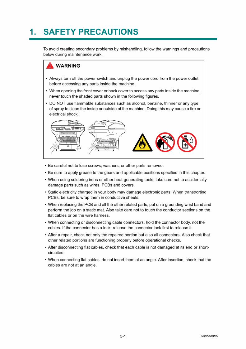
5-1 Confidential
1. SAFETY PRECAUTIONS
To avoid creating secondary problems by mishandling, follow the warnings and precautions below during maintenance work.
• Be careful not to lose screws, washers, or other parts removed.
• Be sure to apply grease to the gears and applicable positions specified in this chapter.
• When using soldering irons or other heat-generating tools, take care not to accidentally damage parts such as wires, PCBs and covers.
• Static electricity charged in your body may damage electronic parts. When transporting PCBs, be sure to wrap them in conductive sheets.
• When replacing the PCB and all the other related parts, put on a grounding wrist band and perform the job on a static mat. Also take care not to touch the conductor sections on the flat cables or on the wire harness.
• When connecting or disconnecting cable connectors, hold the connector body, not the cables. If the connector has a lock, release the connector lock first to release it.
• After a repair, check not only the repaired portion but also all connectors. Also check that other related portions are functioning properly before operational checks.
• After disconnecting flat cables, check that each cable is not damaged at its end or short-circuited.
• When connecting flat cables, do not insert them at an angle. After insertion, check that the cables are not at an angle.
WARNING
• Always turn off the power switch and unplug the power cord from the power outlet before accessing any parts inside the machine.
• When opening the front cover or back cover to access any parts inside the machine, never touch the shaded parts shown in the following figures.
• DO NOT use flammable substances such as alcohol, benzine, thinner or any type of spray to clean the inside or outside of the machine. Doing this may cause a fire or electrical shock.
5-2 Confidential
2. TRANSFERRING RECEIVED FAX DATA
When the machine at the user site requires to be repaired, unplugging the power cord from the wall socket for sending the machine for repair will lose received FAX data if unprinted and left in the machine.
To prevent such data loss, the service personnel should instruct end users (e.g., by telephone) to transfer data to another facsimile machine using the procedure below.
■ Operating Procedure
(1) Connect the machine to be repaired (that has received data in the memory) to the telephone line.
(2) Switch the machine on.
(3) Press the [Menu], [Start], [Menu] and [ ] buttons in this order.
The "MAINTENANCE 06" appears on the LCD.
(4) Call up the "MAINTENANCE 53" using the [ ] and [ ] buttons and press the [OK] button.
The "FAX TRANSFER" appears on the LCD.
(5) To check the number of received files, press the [1] key.
The "1.NO. OF JOBS" appears on the LCD.
Press the [OK] button, and the number of received files appears, just as "NO. OF. JOBS: 10."
Press the [Stop/Exit] button, and the “FAX TRANSFER” appears on the LCD.
(6) To transfer the activity report only, press the [2] key.
The "2.ACTIVITY" appears.
To transfer received files together with the activity report, press the [3] key.
The "3.DOCUMENTS" appears. Note that if there is no received file, the "NO DOCUMENTS" appears.
To transfer the communication list for the latest communication, press the [4] key.
The "4.COM.LIST (NEW)" appears.
To transfer the communication list for last three errors, press the [5] key.
The "5.COM.LIST (ERR3)" appears.
Note: • The number of files that can be transferred at a time is 99. To transfer 100 files or more,
carry out the following procedure more than one time.
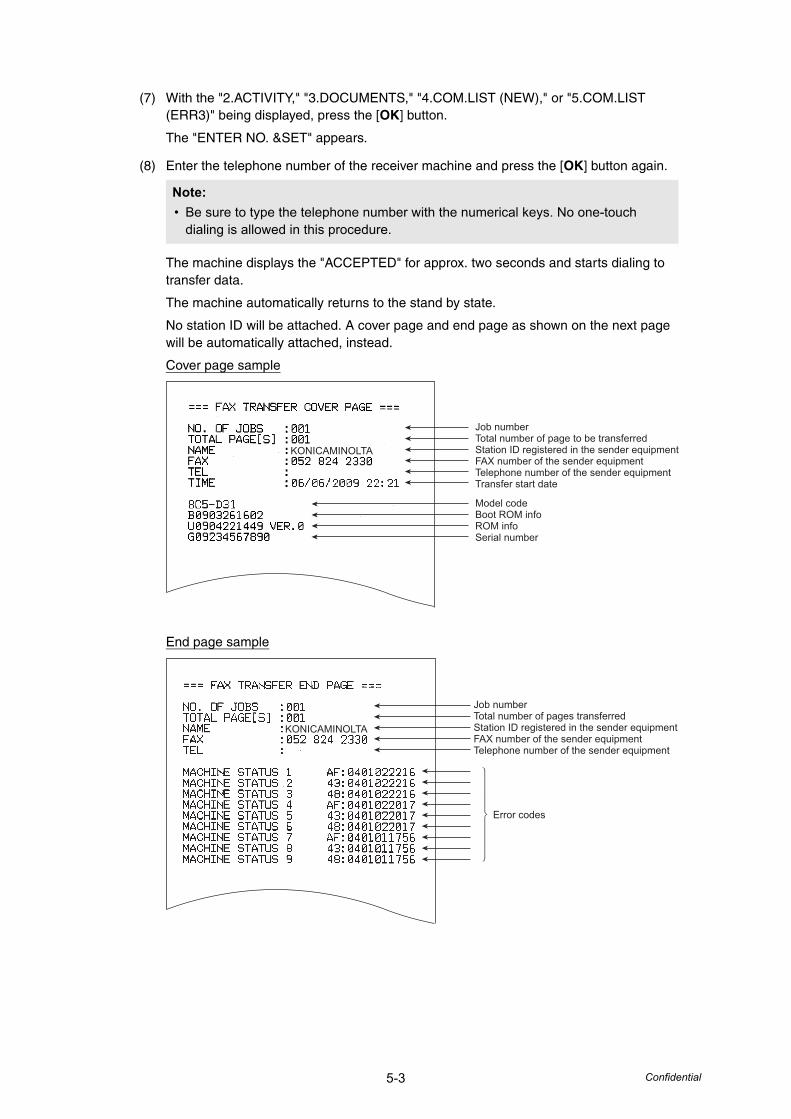
5-3 Confidential
(7) With the "2.ACTIVITY," "3.DOCUMENTS," "4.COM.LIST (NEW)," or "5.COM.LIST (ERR3)" being displayed, press the [OK] button.
The "ENTER NO. &SET" appears.
(8) Enter the telephone number of the receiver machine and press the [OK] button again.
The machine displays the "ACCEPTED" for approx. two seconds and starts dialing to transfer data.
The machine automatically returns to the stand by state.
No station ID will be attached. A cover page and end page as shown on the next page will be automatically attached, instead.
Cover page sample
End page sample
Note: • Be sure to type the telephone number with the numerical keys. No one-touch
dialing is allowed in this procedure.
KONICAMINOLTA
Model codeBoot ROM infoROM infoSerial number
Job numberTotal number of page to be transferredStation ID registered in the sender equipmentFAX number of the sender equipmentTelephone number of the sender equipmentTransfer start date
Error codes
Job numberTotal number of pages transferredStation ID registered in the sender equipmentFAX number of the sender equipmentTelephone number of the sender equipment
KONICAMINOLTA
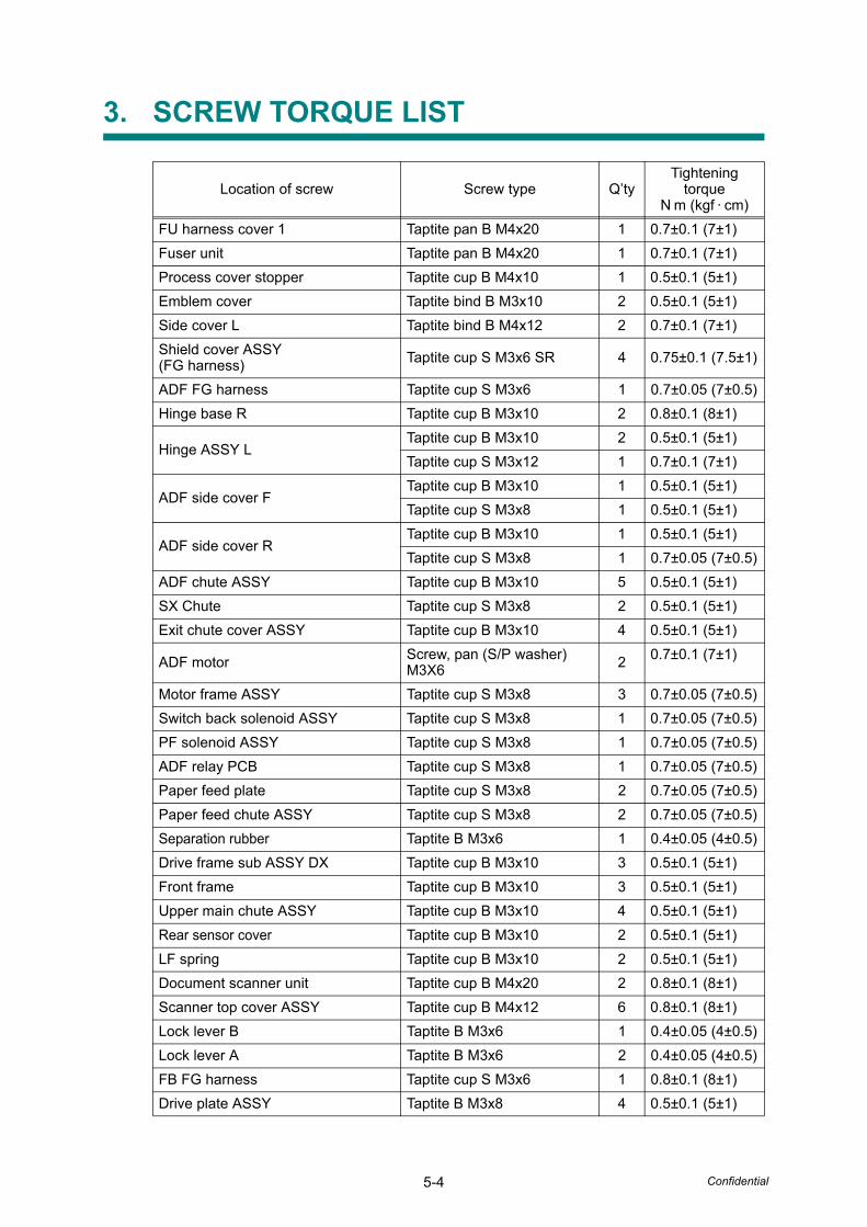
5-4 Confidential
3. SCREW TORQUE LIST
Location of screw Screw type Q’tyTightening
torqueN m (kgf · cm)
FU harness cover 1 Taptite pan B M4x20 1 0.7±0.1 (7±1)Fuser unit Taptite pan B M4x20 1 0.7±0.1 (7±1)Process cover stopper Taptite cup B M4x10 1 0.5±0.1 (5±1)Emblem cover Taptite bind B M3x10 2 0.5±0.1 (5±1)Side cover L Taptite bind B M4x12 2 0.7±0.1 (7±1)Shield cover ASSY(FG harness) Taptite cup S M3x6 SR 4 0.75±0.1 (7.5±1)
ADF FG harness Taptite cup S M3x6 1 0.7±0.05 (7±0.5)Hinge base R Taptite cup B M3x10 2 0.8±0.1 (8±1)
Hinge ASSY LTaptite cup B M3x10 2 0.5±0.1 (5±1)Taptite cup S M3x12 1 0.7±0.1 (7±1)
ADF side cover FTaptite cup B M3x10 1 0.5±0.1 (5±1)Taptite cup S M3x8 1 0.5±0.1 (5±1)
ADF side cover RTaptite cup B M3x10 1 0.5±0.1 (5±1)Taptite cup S M3x8 1 0.7±0.05 (7±0.5)
ADF chute ASSY Taptite cup B M3x10 5 0.5±0.1 (5±1)SX Chute Taptite cup S M3x8 2 0.5±0.1 (5±1)Exit chute cover ASSY Taptite cup B M3x10 4 0.5±0.1 (5±1)
ADF motor Screw, pan (S/P washer) M3X6 2 0.7±0.1 (7±1)
Motor frame ASSY Taptite cup S M3x8 3 0.7±0.05 (7±0.5)Switch back solenoid ASSY Taptite cup S M3x8 1 0.7±0.05 (7±0.5)PF solenoid ASSY Taptite cup S M3x8 1 0.7±0.05 (7±0.5)ADF relay PCB Taptite cup S M3x8 1 0.7±0.05 (7±0.5)Paper feed plate Taptite cup S M3x8 2 0.7±0.05 (7±0.5)Paper feed chute ASSY Taptite cup S M3x8 2 0.7±0.05 (7±0.5)Separation rubber Taptite B M3x6 1 0.4±0.05 (4±0.5)Drive frame sub ASSY DX Taptite cup B M3x10 3 0.5±0.1 (5±1)Front frame Taptite cup B M3x10 3 0.5±0.1 (5±1)Upper main chute ASSY Taptite cup B M3x10 4 0.5±0.1 (5±1)Rear sensor cover Taptite cup B M3x10 2 0.5±0.1 (5±1)LF spring Taptite cup B M3x10 2 0.5±0.1 (5±1)Document scanner unit Taptite cup B M4x20 2 0.8±0.1 (8±1)Scanner top cover ASSY Taptite cup B M4x12 6 0.8±0.1 (8±1)Lock lever B Taptite B M3x6 1 0.4±0.05 (4±0.5)Lock lever A Taptite B M3x6 2 0.4±0.05 (4±0.5)FB FG harness Taptite cup S M3x6 1 0.8±0.1 (8±1)Drive plate ASSY Taptite B M3x8 4 0.5±0.1 (5±1)
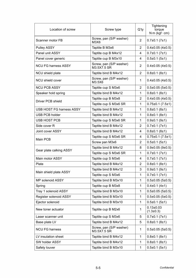
5-5 Confidential
Scanner motor FB Screw, pan (S/P washer) M3X6 2 0.7±0.1 (7±1)
Pulley ASSY Taptite B M3x6 2 0.4±0.05 (4±0.5)Panel unit ASSY Taptite cup B M4x12 4 0.7±0.1 (7±1)Panel cover generic Taptite cup B M3x10 4 0.5±0.1 (5±1)
NCU FG harness ASSY Screw, pan (S/P washer) M3.5X7.5 SR 2 0.4±0.05 (4±0.5)
NCU shield plate Taptite bind B M4x12 2 0.8±0.1 (8±1)
NCU shield cover Screw, pan (S/P washer) M3.5X6 1 0.4±0.05 (4±0.5)
NCU PCB ASSY Taptite cup S M3x6 2 0.5±0.05 (5±0.5)Speaker hold spring Taptite bind B M4x12 1 0.8±0.1 (8±1)
Driver PCB shieldTaptite cup B M3x8 2 0.4±0.05 (4±0.5)Taptite cup S M3x6 SR 1 0.75±0.1 (7.5±1)
USB HOST FG harness ASSY Taptite bind B M4x12 1 0.8±0.1 (8±1)USB PCB holder Taptite bind B M4x12 1 0.8±0.1 (8±1)USB HOST PCB Taptite cup S M3x6 SR 1 0.9±0.1 (9±1)Side cover R Taptite bind B M4x12 2 0.7±0.1 (7±1)Joint cover ASSY Taptite bind B M4x12 4 0.8±0.1 (8±1)
Main PCBTaptite cup S M3x6 SR 4 0.75±0.1 (7.5±1)Screw pan M3x6 2 0.5±0.1 (5±1)
Gear plate calking ASSYTaptite bind B M4x12 8 0.9±0.05 (9±0.5)Taptite cup S M3x6 SR 1 0.7±0.1 (7±1)
Main motor ASSY Taptite cup S M3x6 4 0.7±0.1 (7±1)Plate Taptite bind B M4x12 2 0.8±0.1 (8±1)
Main shield plate ASSYTaptite bind B M4x12 3 0.9±0.1 (9±1)Taptite cup S M3x6 1 0.7±0.1 (7±1)
MP solenoid ASSY Taptite bind B M3x10 1 0.5±0.05 (5±0.5)Spring Taptite cup B M3x8 1 0.4±0.1 (4±1)Tray 1 solenoid ASSY Taptite bind B M3x10 1 0.5±0.05 (5±0.5)Register solenoid ASSY Taptite bind B M3x10 1 0.5±0.05 (5±0.5)Ejector solenoid Taptite bind B M3x10 1 0.5±0.1 (5±1)
New toner actuator Taptite cup B M2x6 1 0.13±0.03 (1.3±0.3)
Laser scanner unit Taptite cup S M3x6 5 0.7±0.1 (7±1)Base plate LV Taptite bind B M4x12 5 0.8±0.1 (8±1)
NCU FG harness Screw, pan (S/P washer) M3.5X7.5 SR 1 0.5±0.05 (5±0.5)
LV insulation sheet Taptite bind B M4x12 1 0.8±0.1 (8±1)SW holder ASSY Taptite bind B M4x12 1 0.8±0.1 (8±1)Safety louver Taptite bind B M3x10 1 0.5±0.1 (5±1)
Location of screw Screw type Q’tyTightening
torqueN m (kgf · cm)

5-6 Confidential
Base plate HV Taptite bind B M4x12 4 0.8±0.1 (8±1)HV insulation sheet Taptite bind B M4x12 1 0.8±0.1 (8±1)High-voltage PS PCB ASSY Taptite bind B M4x12 1 0.8±0.1 (8±1)Toner LED PCB unit ASSY Taptite pan B M3x8 1 0.5±0.1 (5±1)Frame L Taptite bind B M4x12 4 0.8±0.1 (8±1)(Under bar) Taptite bind B M4x12 2 0.7±0.1 (7±1)MP feed frame Taptite bind B M3x8 2 0.5±0.1 (5±1)MP PE sensor ASSY Taptite bind B M3x8 1 0.5±0.1 (5±1)Feed frame Taptite bind B M4x12 2 0.7±0.1 (7±1)PE EG sensor ASSY Taptite bind B M3x8 1 0.5±0.1 (5±1)
Location of screw Screw type Q’tyTightening
torqueN m (kgf · cm)
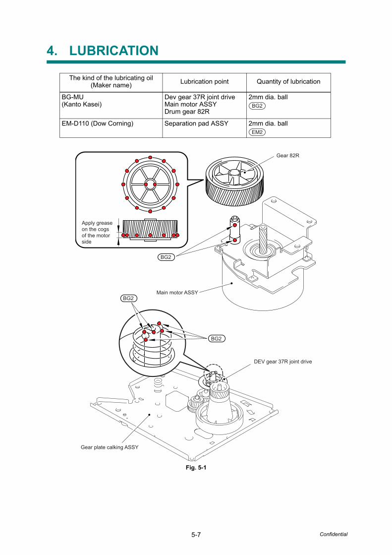
5-7 Confidential
4. LUBRICATION
Fig. 5-1
The kind of the lubricating oil(Maker name) Lubrication point Quantity of lubrication
BG-MU (Kanto Kasei)
Dev gear 37R joint driveMain motor ASSYDrum gear 82R
2mm dia. ball
EM-D110 (Dow Corning) Separation pad ASSY 2mm dia. ball
BG2
EM2
Apply grease on the cogs of the motor side
Main motor ASSY
Gear 82R
BG2
BG2
BG2
DEV gear 37R joint drive
Gear plate calking ASSY
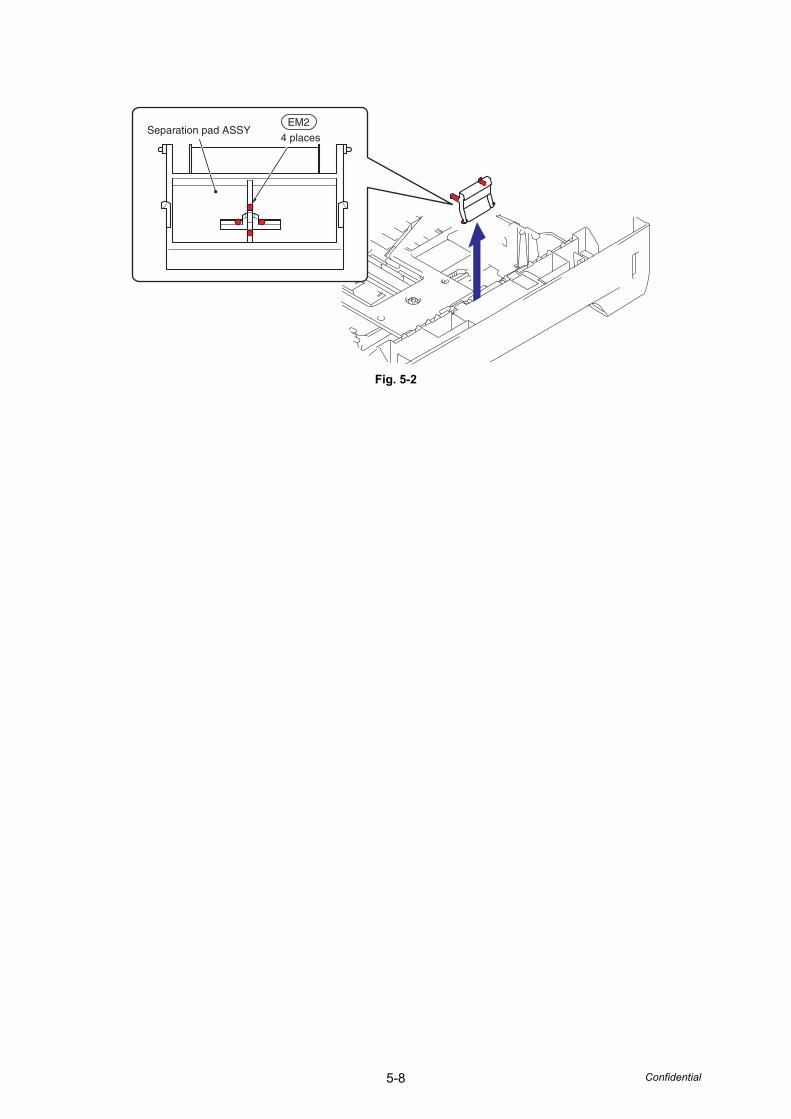
5-8 Confidential
Fig. 5-2
EM2
4 placesSeparation pad ASSY
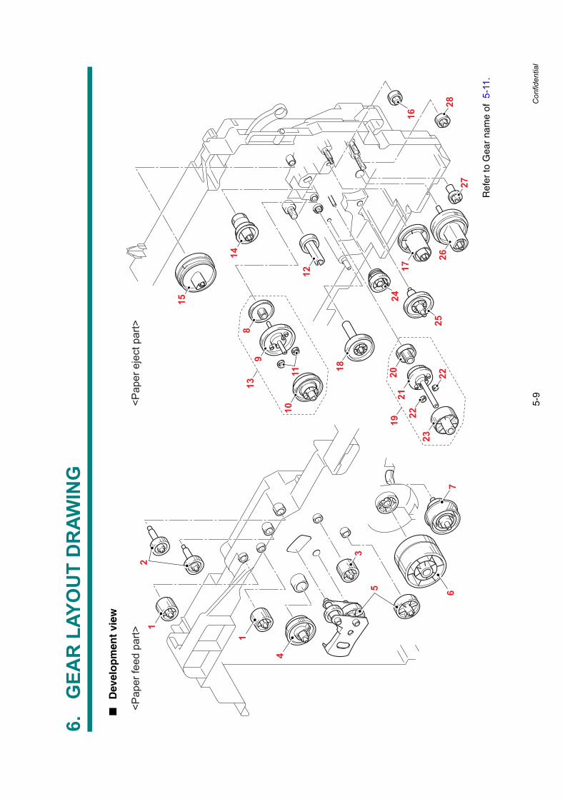
5-9
Confidential
6.G
EAR
LAY
OU
T D
RAW
ING
■D
evel
op
men
t vi
ew
Ref
er to
Gea
r na
me
of 5
-11.
14
15
89
1110
17
26
18
12
19
13
2021
2223
2827
22
24
25
16
2
1
1
4
653
7
<Pap
er fe
ed p
art>
<Pap
er e
ject
par
t>
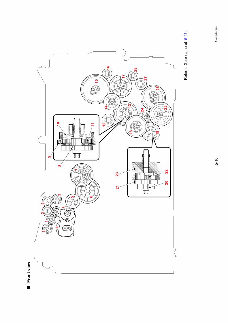
5-10
Confidential
■F
ron
t vi
ew
Ref
er to
Gea
r na
me
of 5
-11.
27
28
17
16
15
14 13
12
18 1926
2524
2321
8
9
1110
2220
11
22
35
5
4
6
7

5-11
Confidential
■G
ear
nam
e
1-
EJE
CTO
R G
EA
R 1
615
-M
P G
EA
R 5
5/60
SE
CTO
R
2-
IDLE
GE
AR
16B
16A
32P
PP
17 #
#G
EA
R 1
7 (w
hite
)
3-
EJE
CTO
R G
EA
R 1
617
-F
EE
DE
R G
EA
R 4
8
4-
EJE
CT
GE
AR
28
SE
CTO
R18
-D
X G
EA
R 2
7/68
L
5-
EJE
CTO
R G
EA
R 2
219
-P
/P D
IFF
ER
EN
TIA
L
6A
32P
PP
0U #
#F
US
ER
GE
AR
39R
H/R
DR
IVE
20-
P/P
GE
AR
17
CE
NT
ER
7-
FU
SE
R G
EA
R 1
7/63
R P
EN
DU
LUM
21-
P/P
GE
AR
32C
AR
RIE
R
8-
RE
GIS
TE
R G
EA
R 2
1 C
EN
TE
R22
-P
/P G
EA
R 1
5 P
LAN
ETA
RY
9-
RE
GIS
TE
R G
EA
R 4
8 C
AR
RIE
R23
-P
/P G
EA
R 1
47/3
7 IN
TE
RN
AL
10-
RE
GIS
TE
R G
EA
R 1
59/4
3 IN
TE
RN
AL
24-
P/P
GE
AR
29
CLU
TC
H C
AM
11-
RE
GIS
TOR
GE
AR
19
PLA
NE
TAR
Y25
-T
1 G
EA
R 3
1/47
12-
GE
AR
23
26-
T1
GE
AR
50/
45 S
EC
TOR
13-
RE
GIS
TE
R D
IFF
ER
EN
TIA
L27
A32
P P
P16
##
GE
AR
20
14-
FE
ED
ER
GE
AR
21/
31 P
EN
DU
LUM
28-
GE
AR
17
(bla
ck)
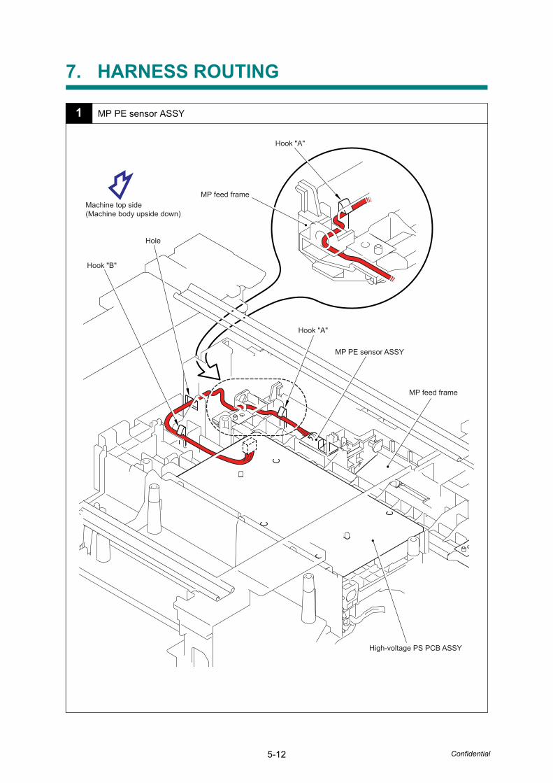
5-12 Confidential
7. HARNESS ROUTING
1 MP PE sensor ASSY
High-voltage PS PCB ASSY
Hook "B"
MP feed frame
MP feed frame
Hole
Hook "A"
Hook "A"
Machine top side(Machine body upside down)
MP PE sensor ASSY
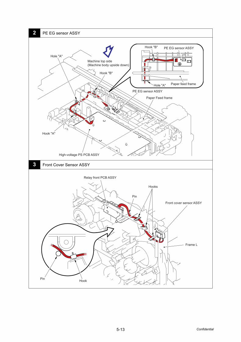
5-13 Confidential
2 PE EG sensor ASSY
3 Front Cover Sensor ASSY
PE EG sensor ASSY
Paper feed frame
Hook "B"
Hole "A"
PE EG sensor ASSY
Paper Feed frame
High-voltage PS PCB ASSY
Hook "A"
Hole "A"Machine top side(Machine body upside down)
Hook "B"
Front cover sensor ASSY
Relay front PCB ASSY
Hooks
Frame L
Pin
HookPin
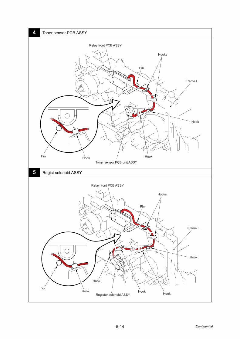
5-14 Confidential
4 Toner sensor PCB ASSY
5 Regist solenoid ASSY
Toner sensor PCB unit ASSY
Relay front PCB ASSY
Hooks
Hook
Hook
Frame L
HookPin
Pin
Register solenoid ASSY
Frame L
Relay front PCB ASSY
Hooks
Hook
HookHook
Hook
Hook
Pin
Pin
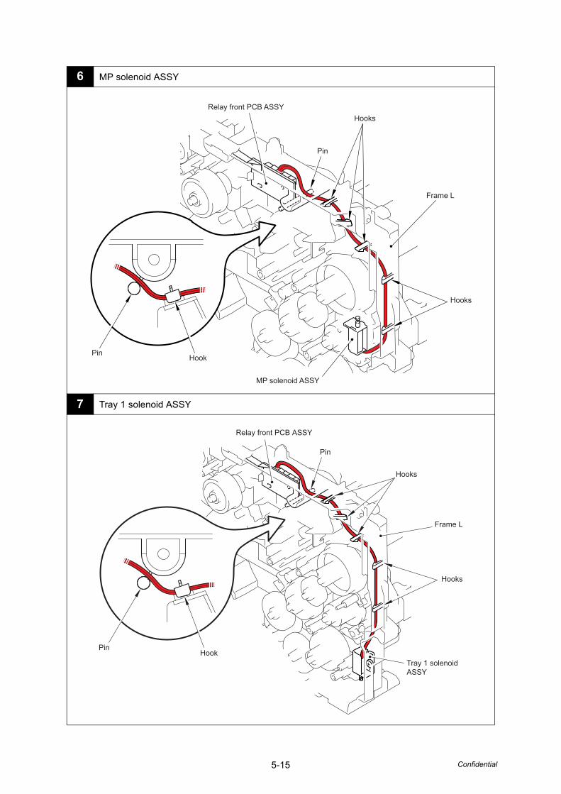
5-15 Confidential
6 MP solenoid ASSY
7 Tray 1 solenoid ASSY
Relay front PCB ASSY
MP solenoid ASSY
Frame L
Hook
Hooks
Hooks
Pin
Pin
Tray 1 solenoid ASSY
Relay front PCB ASSY
Frame L
Hooks
Hooks
Hook
Pin
Pin
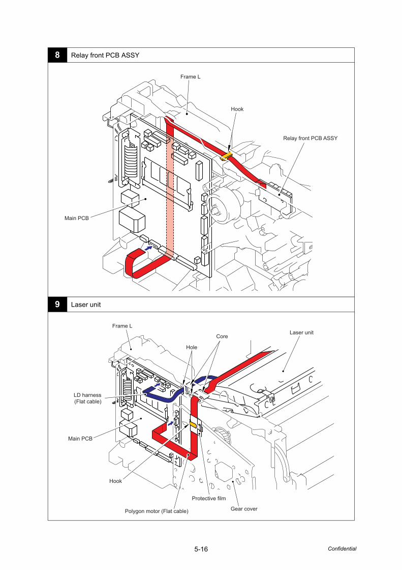
5-16 Confidential
8 Relay front PCB ASSY
9 Laser unit
Relay front PCB ASSY
Main PCB
Hook
Frame L
Laser unitFrame L
Hole
Core
Hook
Gear cover
Main PCB
Polygon motor (Flat cable)
Protective film
LD harness(Flat cable)
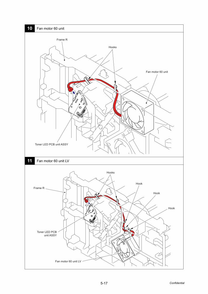
5-17 Confidential
10 Fan motor 60 unit
11 Fan motor 60 unit LV
Frame R
Hooks
Fan motor 60 unit
Toner LED PCB unit ASSY
Frame R
Hooks
Hook
Hook
Hook
Fan motor 60 unit LV
Toner LED PCBunit ASSY
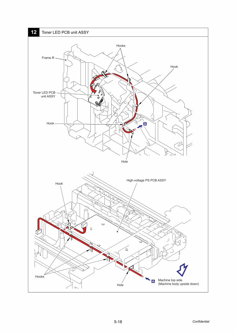
5-18 Confidential
12 Toner LED PCB unit ASSY
Frame R
Hooks
Hook
Hook
Hole
Toner LED PCBunit ASSY
Machine top side(Machine body upside down)
High-voltage PS PCB ASSYHook
Hooks
Hole
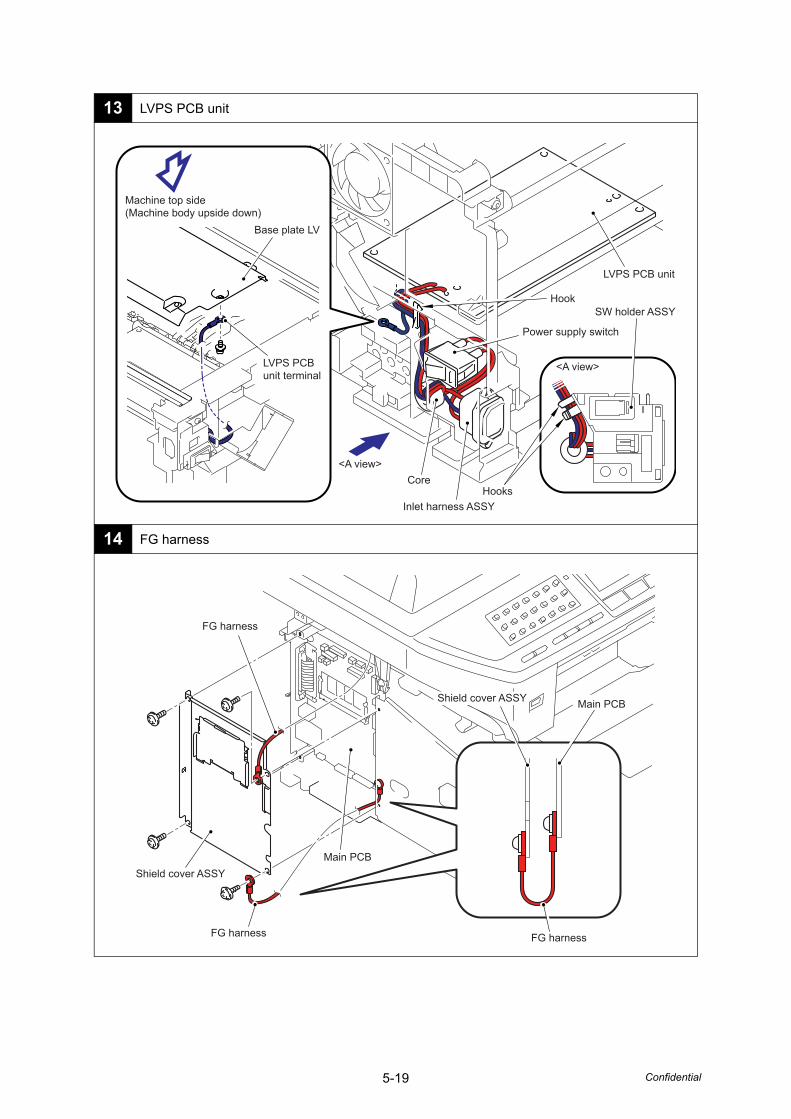
5-19 Confidential
13 LVPS PCB unit
14 FG harness
LVPS PCB unit
Inlet harness ASSY
Power supply switch
Hook
HooksCore
<A view>
<A view>
SW holder ASSY
LVPS PCBunit terminal
Base plate LV
Machine top side(Machine body upside down)
Shield cover ASSY
Shield cover ASSY
FG harness
FG harness
FG harness
Main PCB
Main PCB
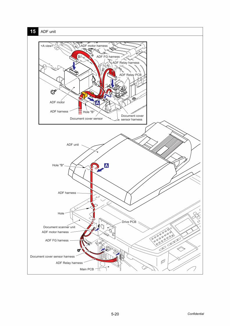
5-20 Confidential
15 ADF unit
Hole "B"
Hole "B"
Hole
ADF Relay PCB
ADF unit
ADF harness
ADF harness
ADF motor harness
ADF motor harness
ADF motor
ADF FG harness
ADF FG harness
ADF Relay harness
ADF Relay harness
Drive PCB
Document cover sensor harness
Document coversensor harnessDocument cover sensor
Document scanner unit
Main PCB
<A view>
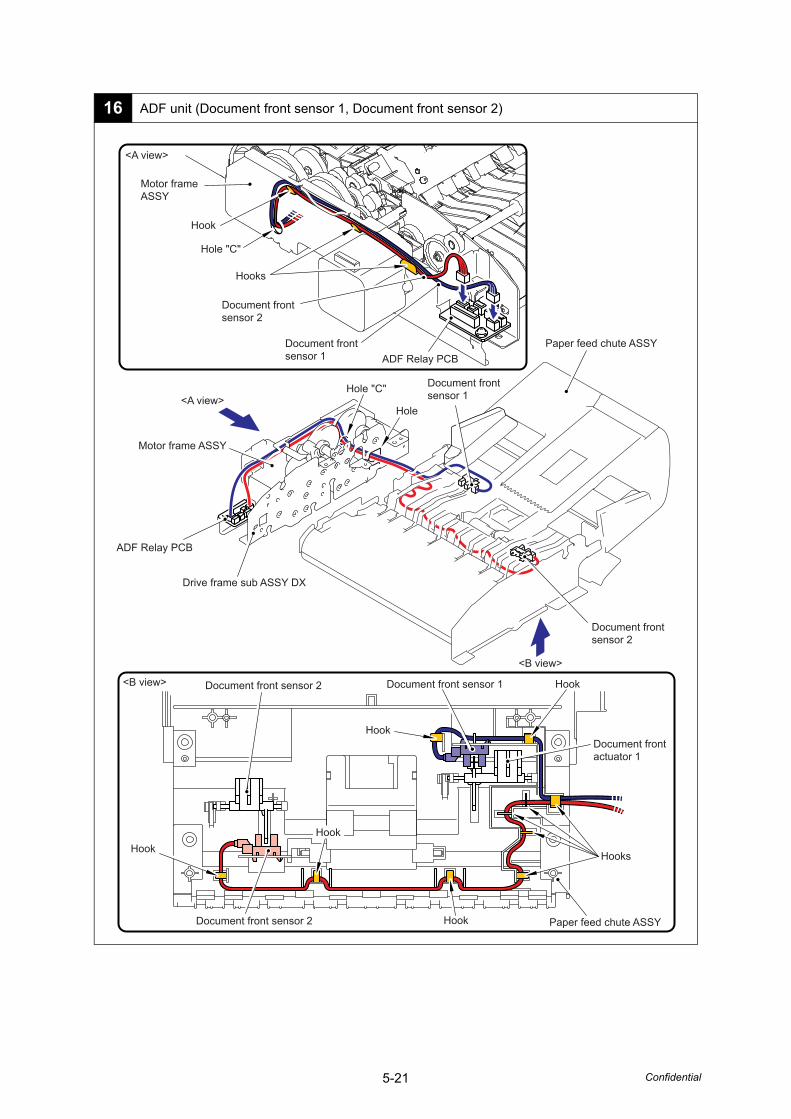
5-21 Confidential
16 ADF unit (Document front sensor 1, Document front sensor 2)
Document front sensor 1
Document front sensor 2
Document frontsensor 1
Document frontsensor 2
Document frontsensor 2
Document frontsensor 1
Document frontactuator 1
Paper feed chute ASSY
Document front sensor 2
Hole "C"
Hole "C"
Hole
Hook
Hooks
Hook
Hook
Hook
Hook
HooksHook
Paper feed chute ASSY
ADF Relay PCB
Drive frame sub ASSY DX
Motor frameASSY
Motor frame ASSY
ADF Relay PCB
<A view>
<A view>
<B view>
<B view>
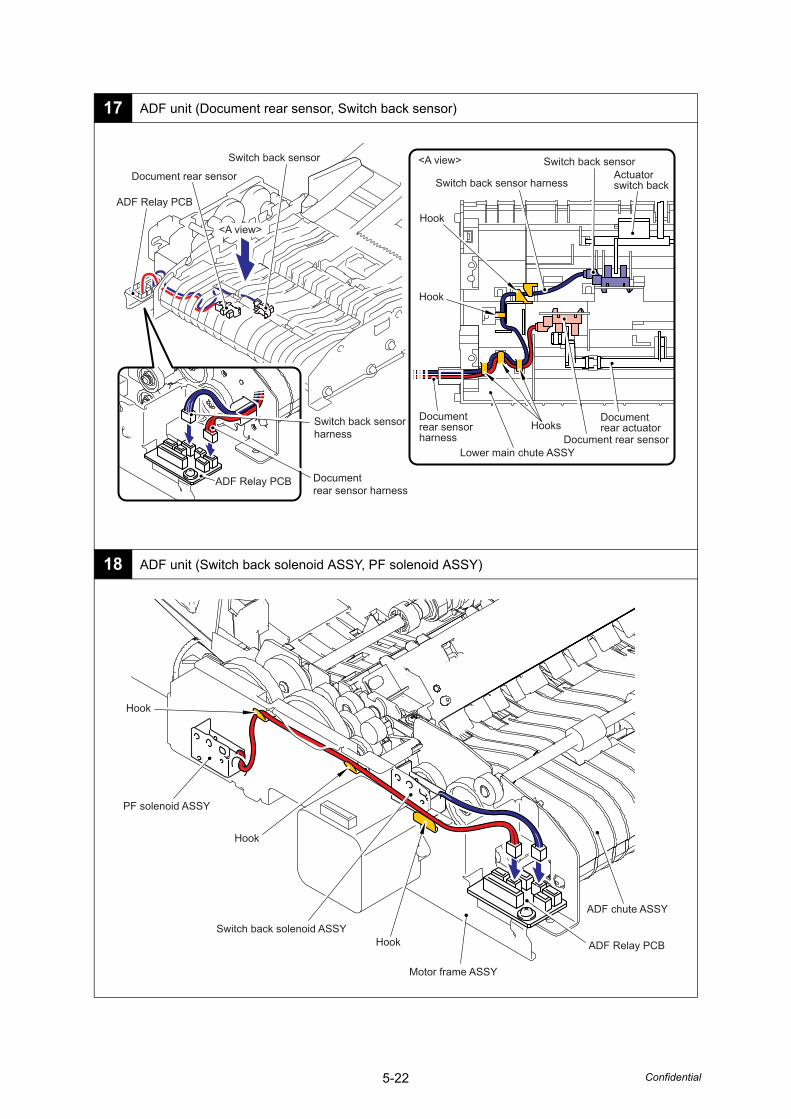
5-22 Confidential
17 ADF unit (Document rear sensor, Switch back sensor)
18 ADF unit (Switch back solenoid ASSY, PF solenoid ASSY)
Documentrear actuator
Actuatorswitch back
Lower main chute ASSY
Hook
Hooks
HookADF Relay PCB
ADF Relay PCB
<A view>
<A view>Document rear sensor
Switch back sensor
Document rear sensor
Documentrear sensor harness
Documentrear sensorharness
Switch back sensor
Switch back sensorharness
Switch back sensor harness
ADF chute ASSY
Hook
Hook
HookSwitch back solenoid ASSY
PF solenoid ASSY
ADF Relay PCB
Motor frame ASSY
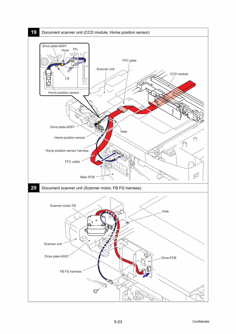
5-23 Confidential
19 Document scanner unit (CCD module, Home position sensor)
20 Document scanner unit (Scanner motor, FB FG harness)
Main PCB
CCD module
FFC cable
Home position sensor
Home position sensor
Drive plate ASSY
Drive plate ASSY
Home position sensor harness
FFC plate
Hole
Scanner unit
Hook Pin
Lib
Drive plate ASSY Drive PCB
Scanner unit
Scanner motor FB
FB FG harness
Hole
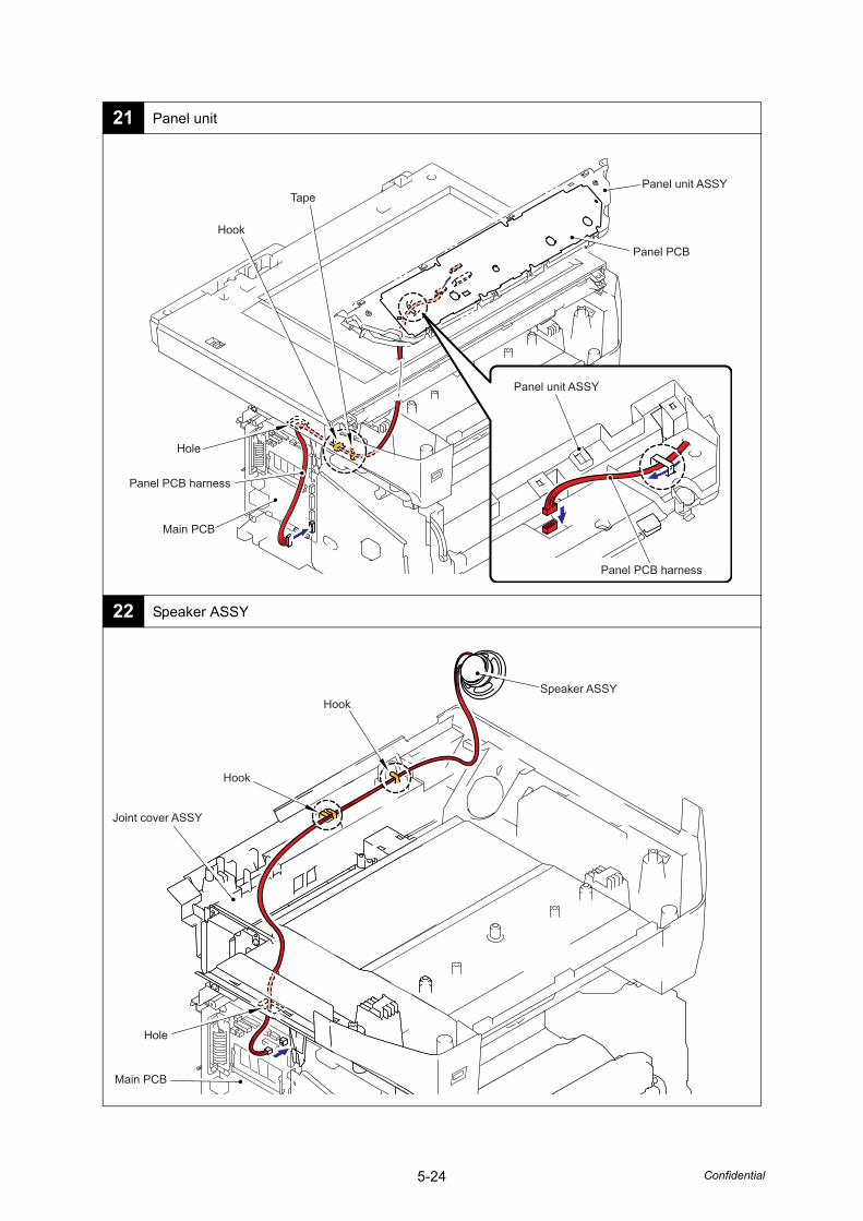
5-24 Confidential
21 Panel unit
22 Speaker ASSY
Panel unit ASSY
Panel PCB
Panel unit ASSY
Panel PCB harness
Panel PCB harness
Main PCB
Hole
Hook
Tape
Joint cover ASSY
HookSpeaker ASSY
Hook
Main PCB
Hole
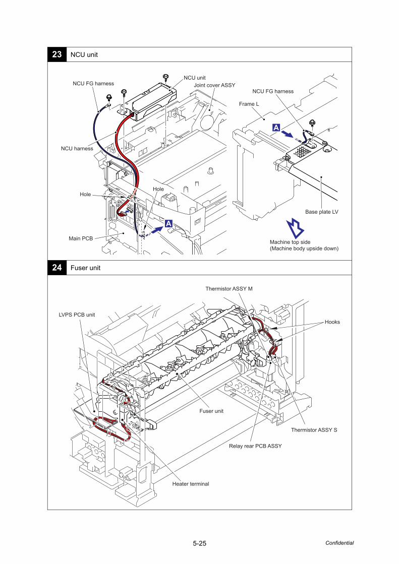
5-25 Confidential
23 NCU unit
24 Fuser unit
NCU FG harnessNCU FG harness
Base plate LV
NCU harness
NCU unit
HoleHole
Joint cover ASSY
Frame L
Main PCBMachine top side(Machine body upside down)
Hooks
Fuser unit
Thermistor ASSY S
Thermistor ASSY M
Relay rear PCB ASSY
LVPS PCB unit
Heater terminal
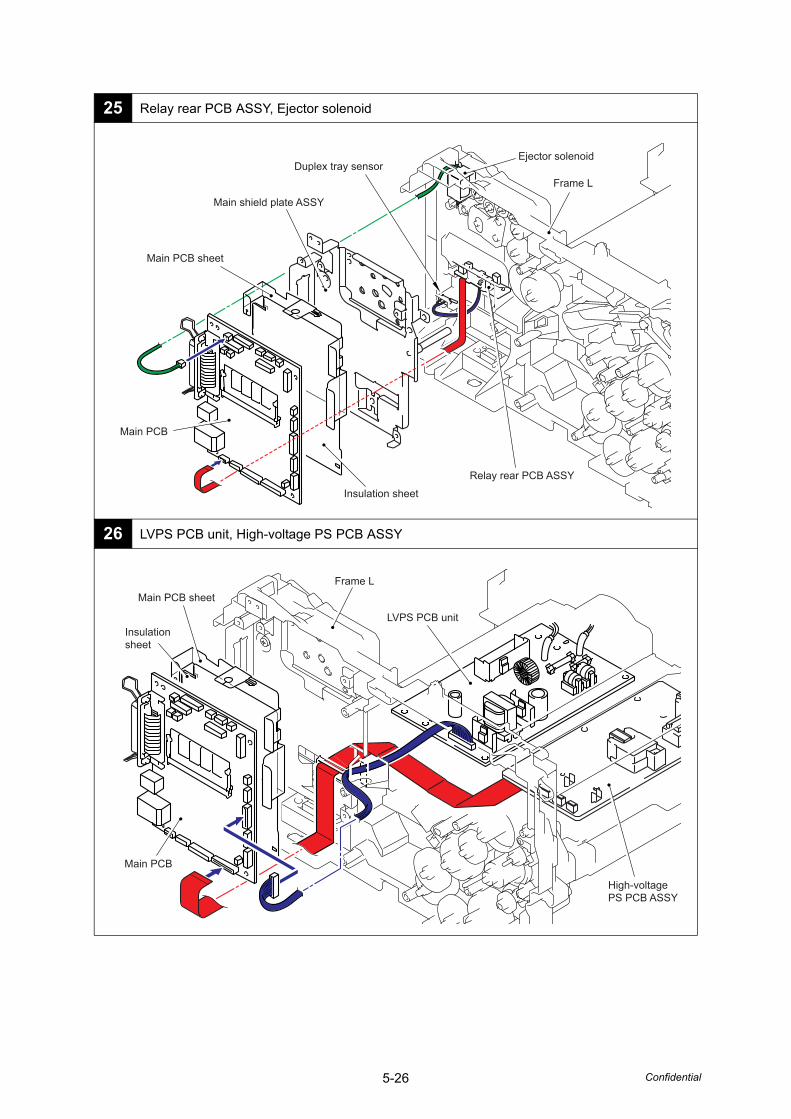
5-26 Confidential
25 Relay rear PCB ASSY, Ejector solenoid
26 LVPS PCB unit, High-voltage PS PCB ASSY
Main shield plate ASSY
Relay rear PCB ASSY
Insulation sheet
Duplex tray sensor
Main PCB sheet
Frame L
Ejector solenoid
Main PCB
Insulationsheet
Main PCB sheet
Main PCB
Frame L
LVPS PCB unit
High-voltagePS PCB ASSY
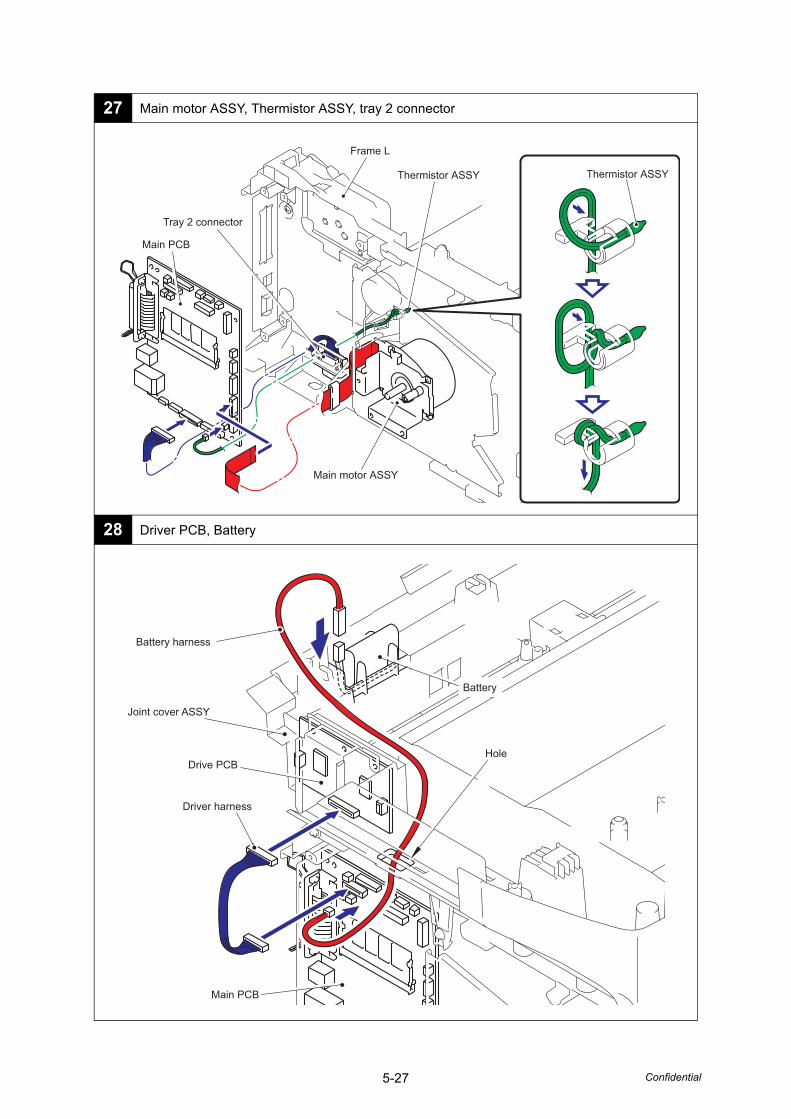
5-27 Confidential
27 Main motor ASSY, Thermistor ASSY, tray 2 connector
28 Driver PCB, Battery
Frame L
Thermistor ASSY Thermistor ASSY
Main motor ASSY
Tray 2 connector
Main PCB
Main PCB
Drive PCB
Joint cover ASSY
Driver harness
Battery harness
Battery
Hole
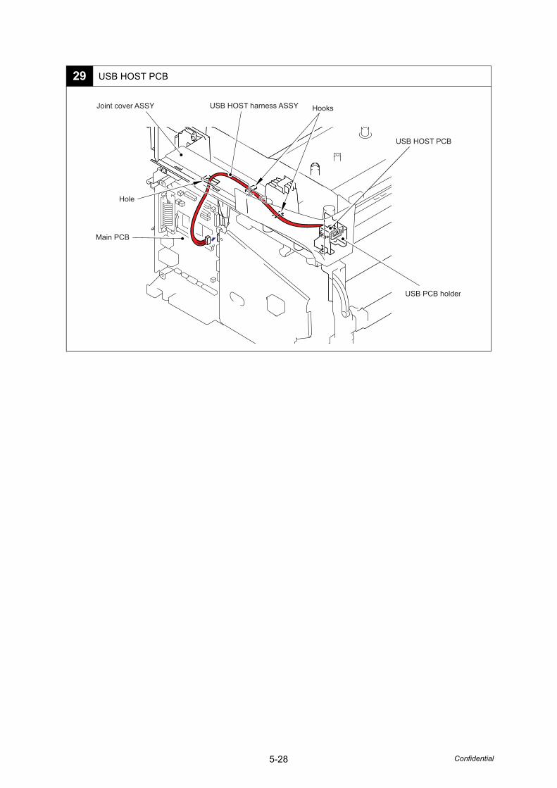
5-28 Confidential
29 USB HOST PCB
Joint cover ASSY USB HOST harness ASSY Hooks
Main PCB
USB PCB holder
USB HOST PCB
Hole
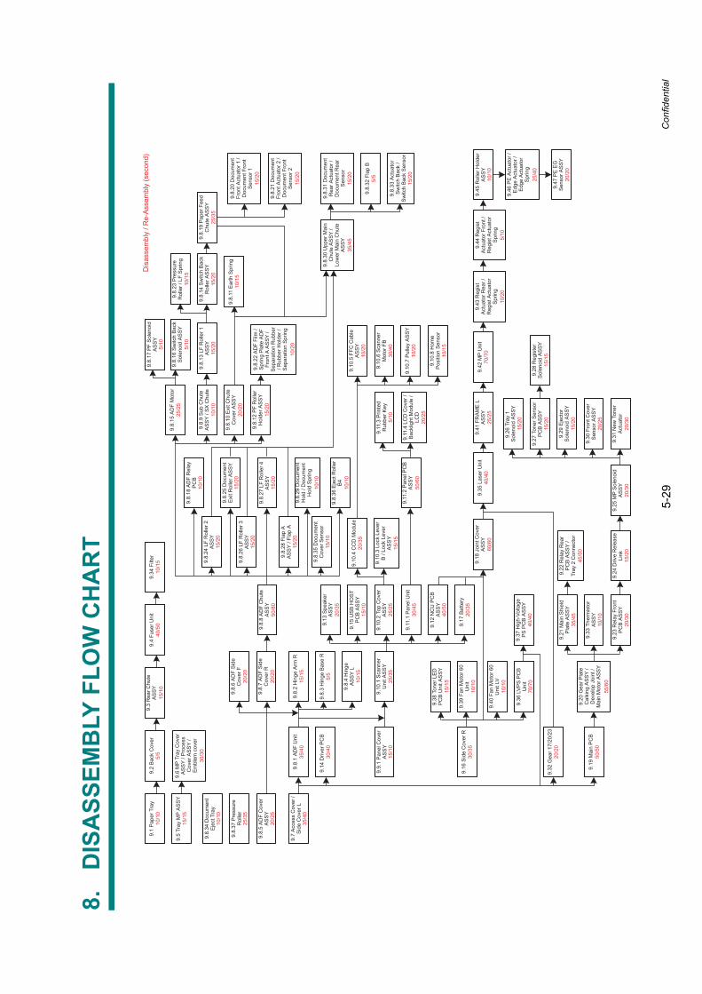
5-29
Confidential
8.D
ISA
SSEM
BLY
FLO
W C
HA
RT
Dis
asse
mbl
y / R
e-A
ssem
bly
(sec
ond)
35/4
545
/50
70/7
0
25/4
0
50/6
0
30/4
0
35/4
5
9.3
Rea
r Chu
teA
SS
Y9.
4 Fu
ser U
nit
9.1
Pap
er T
ray
10/1
09.
2 B
ack
Cov
er9.
34 F
ilter
9.5
Tray
MP
AS
SY
15/1
59.
6 M
P Tr
ay C
over
AS
SY
/ Pro
cess
Cov
er A
SS
Y /
Em
blem
cov
er
9.8.
37 P
ress
ure
Rol
ler
9.8.
34 D
ocum
ent
Eje
ct T
ray
10/1
0
9.8.
5 A
DF
Cov
erA
SS
Y9.
8.7
AD
F S
ide
Cov
er R
9.8.
6 A
DF
Sid
eC
over
F
9.7
Acc
ess
Cov
er /
Sid
e C
over
L9.
8.1
AD
F U
nit
9.14
Driv
er P
CB
9.9.
1 P
anel
Cov
erA
SS
Y9.
10.1
Sca
nner
Uni
t AS
SY
9.8.
2 H
inge
Arm
R15
/15
9.8.
4 H
inge
AS
SY
L
9.8.
3 H
inge
Bas
e R
9.17
Bat
tery
9.12
NC
U P
CB
AS
SY
9.11
.1 P
anel
Uni
t
9.10
.2 T
op C
over
AS
SY
9.15
US
B H
OS
TP
CB
AS
SY
9.13
Spe
aker
AS
SY
9.16
Sid
e C
over
R
9.38
Ton
er L
ED
PC
B U
nit A
SS
Y15
/15
9.39
Fan
Mot
or 6
0U
nit
10/1
0
9.40
Fan
Mot
or 6
0U
nit L
V10
/10
9.36
LV
PS
PC
BU
nit
9.37
Hig
h-Vo
ltage
PS
PC
B A
SS
Y
9.32
Gea
r 17/
20/2
3
9.19
Mai
n P
CB
50/5
0
9.18
Joi
nt C
over
AS
SY
9.20
Gea
r Pla
teC
alki
ng A
SS
Y /
Dev
elop
Joi
nt /
Mai
n M
otor
AS
SY
9.21
Mai
n S
hiel
dP
late
AS
SY
9.23
Rel
ay F
ront
PC
B A
SS
Y
9.33
The
rmis
tor
AS
SY
10/1
0
9.22
Rel
ay R
ear
PC
B A
SS
Y /
Tray
2 C
onne
ctor
9.24
Driv
e R
elea
seLi
nk15
/20
9.25
MP
Sol
enoi
dA
SS
Y
9.26
Tra
y 1
Sol
enoi
d A
SS
Y15
/20
15/2
0
15/2
0
9.27
Ton
er S
enso
rP
CB
AS
SY
9.29
Eje
ctor
Sol
enoi
d A
SS
Y
9.28
Reg
iste
rS
olen
oid
AS
SY
15/1
5
9.30
Fro
nt C
over
Sen
sor A
SS
Y
9.31
New
Ton
erA
ctua
tor
9.35
Las
er U
nit
9.41
FR
AM
E L
AS
SY
9.42
MP
Uni
t9.
43 R
egis
tA
ctua
tor R
ear /
Reg
ist A
ctua
tor
Spr
ing
9.44
Reg
ist
Act
uato
r Fro
nt /
Reg
ist A
ctua
tor
Spr
ing
9.45
Rol
ler H
olde
rA
SS
Y10
/10
9.46
PE
Act
uato
r /E
dge
Act
uato
r /E
dge
Act
uato
rS
prin
g
9.47
PE
EG
Sen
sor A
SS
Y
9.11
.2 P
anel
PC
BA
SS
Y9.
11.4
LC
D C
over
/B
ackl
ight
Mod
ule
/LC
D
9.11
.3 P
rinte
dR
ubbe
r Key
9.10
.3 L
ock
Leve
rB
/ Lo
ck L
ever
AS
SY
15/1
5
9.10
.4 C
CD
Mod
ule
9.10
.8 H
ome
Pos
ition
Sen
sor
9.10
.6 S
cann
erM
otor
FB
9.10
.5 F
FC C
able
AS
SY
9.10
.7 P
ulle
y A
SS
Y
9.8.
8 A
DF
Chu
teA
SS
Y
9.8.
36 E
ject
Rol
ler
B4
10/1
0
9.8.
35 D
ocum
ent
Cov
er S
enso
r
9.8.
29 D
ocum
ent
Hol
d / D
ocum
ent
Hol
d S
prin
g10
/10
9.8.
28 F
lap
AA
SS
Y / F
lap
A15
/20
9.8.
27 L
F R
olle
r 4A
SS
Y15
/20
9.8.
26 L
F R
olle
r 3A
SS
Y15
/20
9.8.
25 D
ocum
ent
Exi
t Rol
ler A
SS
Y15
/20
9.8.
24 L
F R
olle
r 2A
SS
Y15
/20
9.8.
30 U
pper
Mai
nC
hute
AS
SY
/Lo
wer
Mai
n C
hute
AS
SY
9.8.
31 D
ocum
ent
Rea
r Act
uato
r /D
ocum
ent R
ear
Sen
sor
15/2
0
9.8.
33 A
ctua
tor
Sw
itch
Bac
k /
Sw
itch
Bac
k S
enso
r15
/20
9.8.
18 A
DF
Rel
ayP
CB
10/1
0
9.8.
15 A
DF
Mot
or
9.8.
17 P
F S
olen
oid
AS
SY
9.8.
16 S
witc
h B
ack
Sol
enoi
d A
SS
Y
9.8.
9 S
ub C
hute
AS
SY
/ SX
Chu
te10
/10
9.8.
13 L
F R
olle
r 1A
SS
Y15
/20
9.8.
23 P
ress
ure
Rol
ler /
LF
Spr
ing
9.8.
14 S
witc
h B
ack
Rol
ler A
SS
Y15
/20
9.8.
19 P
aper
Fee
dC
hute
AS
SY
9.8.
12 P
F R
olle
rH
olde
r AS
SY
9.8.
10 E
xit C
hute
Cov
er A
SS
Y9.
8.11
Ear
th S
prin
g
9.8.
22 A
DF
Film
/S
prin
g P
late
AD
FFr
ont A
AS
SY
/S
epar
atio
n R
ubbe
r/ R
ubbe
r Hol
der /
Sep
arat
ion
Spr
ing
9.8.
20 D
ocum
ent
Fron
t Act
uato
r 1 /
Doc
umen
t Fro
ntS
enso
r 115
/20
9.8.
21 D
ocum
ent
Fron
t Act
uato
r 2 /
Doc
umen
t Fro
ntS
enso
r 215
/20
9.8.
32 F
lap
B
15/1
0
15/1
0
15/1
0
15/1
0
5/5
5/5
20/2
0
20/2
0
20/2
0
20/2
0
20/2
0
5/5
40/5
0
40/5
0
20/3
020
/30
20/3
0
10/1
5
10/1
5
10/1
5
10/1
5
10/1
5
5/10
5/10
5/10
5/10
55/6
020
/25
20/2
5
20/2
5
25/2
5
25/2
5
25/2
5
30/3
0
40/4
070
/70
60/6
040
/40
25/3
5
25/3
5
10/2
0
10/2
0
10/2
0
10/2
0
15/2
0
25/3
5
35/4
035
/40
20/3
5
20/3
5
50/8
0
30/4
0
20/3
5
30/4
5
30/3
5
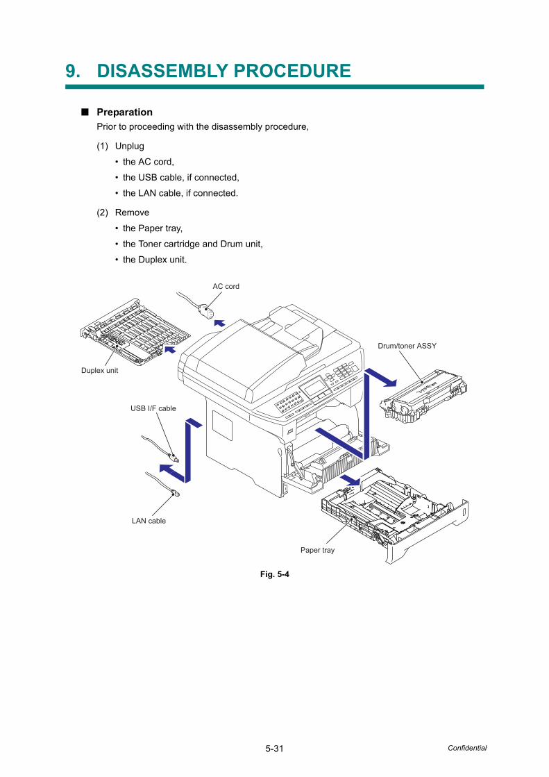
5-31 Confidential
9. DISASSEMBLY PROCEDURE
■ PreparationPrior to proceeding with the disassembly procedure,
(1) Unplug
• the AC cord,
• the USB cable, if connected,
• the LAN cable, if connected.
(2) Remove
• the Paper tray,
• the Toner cartridge and Drum unit,
• the Duplex unit.
Fig. 5-4
Duplex unit
Paper tray
Drum/toner ASSY
AC cord
USB I/F cable
LAN cable
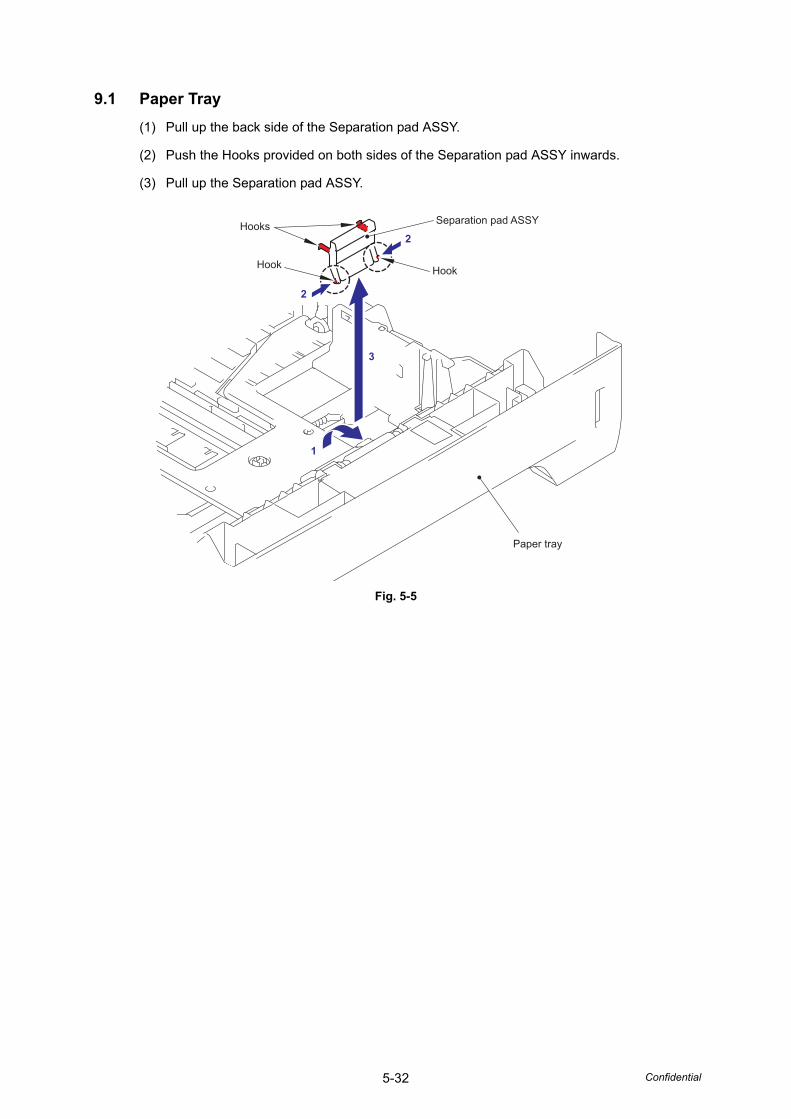
5-32 Confidential
9.1 Paper Tray (1) Pull up the back side of the Separation pad ASSY.
(2) Push the Hooks provided on both sides of the Separation pad ASSY inwards.
(3) Pull up the Separation pad ASSY.
Fig. 5-5
Separation pad ASSY
Hook
Hooks
Hook
1
3
2
2
Paper tray
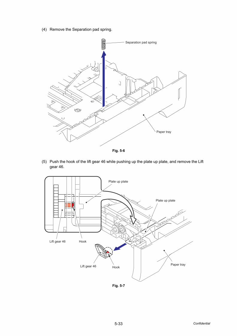
5-33 Confidential
(4) Remove the Separation pad spring.
Fig. 5-6
(5) Push the hook of the lift gear 46 while pushing up the plate up plate, and remove the Lift gear 46.
Fig. 5-7
Paper tray
Separation pad spring
Hook
Hook
Paper tray
Plate up plate
Plate up plate
Lift gear 46
Lift gear 46
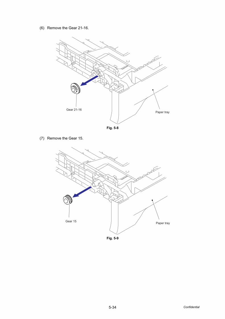
5-34 Confidential
(6) Remove the Gear 21-16.
Fig. 5-8
(7) Remove the Gear 15.
Fig. 5-9
Paper trayGear 21-16
Paper trayGear 15
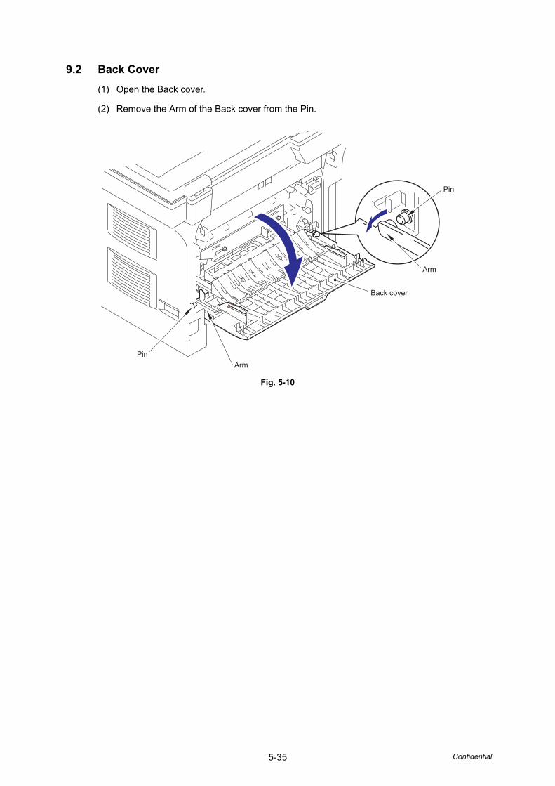
5-35 Confidential
9.2 Back Cover (1) Open the Back cover.
(2) Remove the Arm of the Back cover from the Pin.
Fig. 5-10
Back cover
Pin
Arm
ArmPin
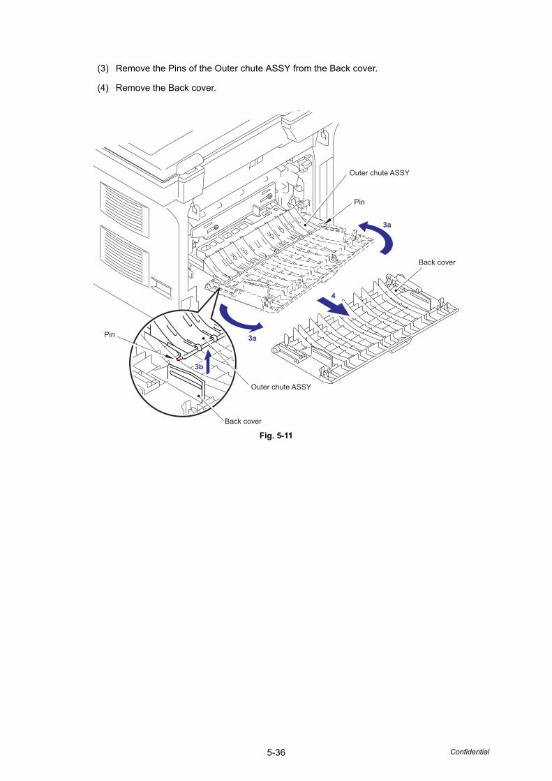
5-36 Confidential
(3) Remove the Pins of the Outer chute ASSY from the Back cover.
(4) Remove the Back cover.
Fig. 5-11
3a
3a
3b
4
Pin
Pin
Back cover
Back cover
Outer chute ASSY
Outer chute ASSY
3b
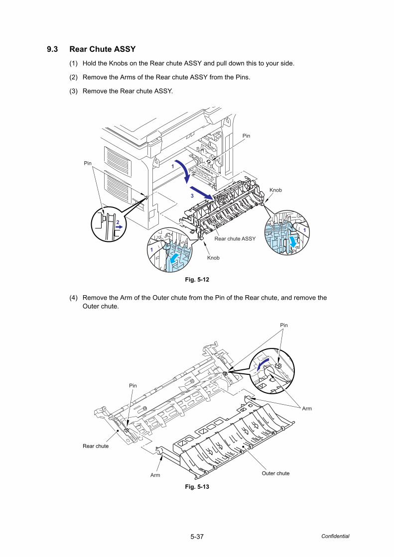
5-37 Confidential
9.3 Rear Chute ASSY(1) Hold the Knobs on the Rear chute ASSY and pull down this to your side.
(2) Remove the Arms of the Rear chute ASSY from the Pins.
(3) Remove the Rear chute ASSY.
Fig. 5-12
(4) Remove the Arm of the Outer chute from the Pin of the Rear chute, and remove the Outer chute.
Fig. 5-13
1
1
1
2
3
Pin
Pin
Knob
Knob
Rear chute ASSY
Arm
Pin
Pin
Arm
Outer chute
Rear chute
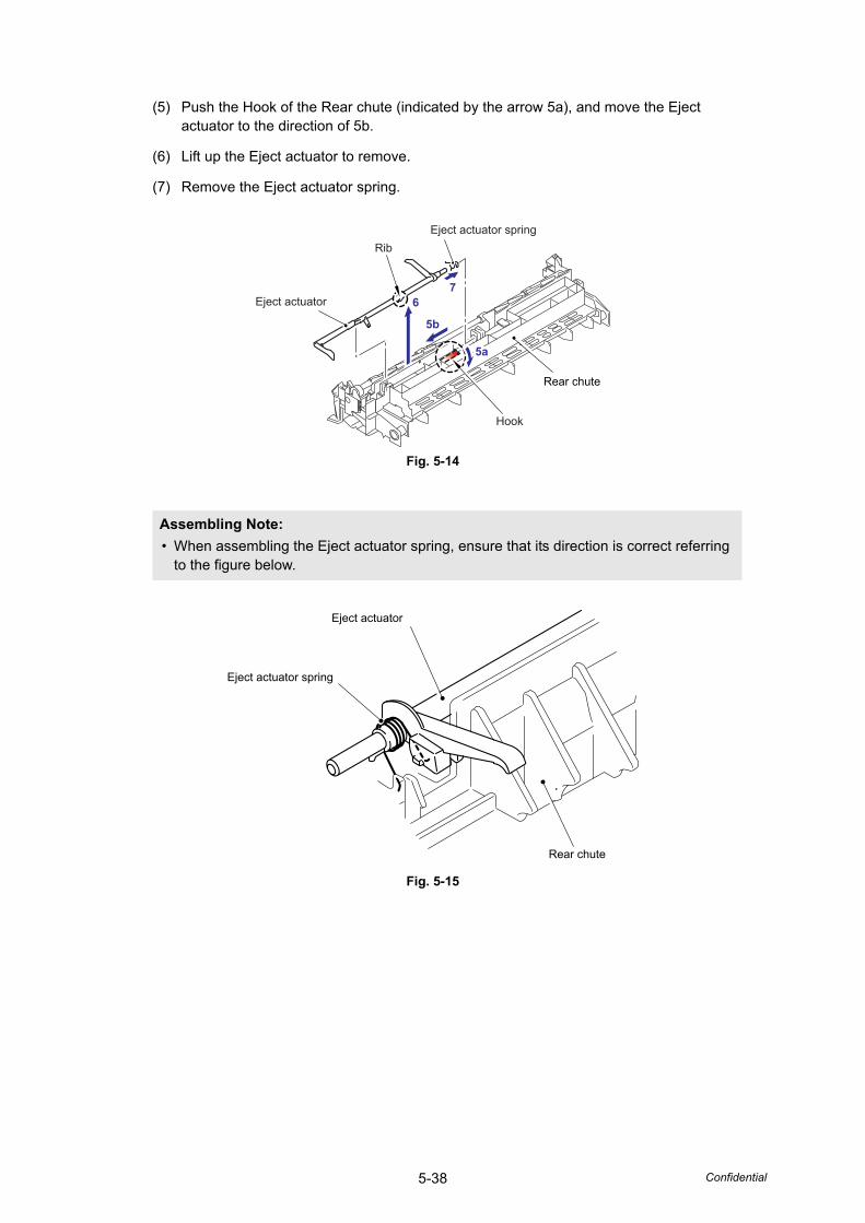
5-38 Confidential
(5) Push the Hook of the Rear chute (indicated by the arrow 5a), and move the Eject actuator to the direction of 5b.
(6) Lift up the Eject actuator to remove.
(7) Remove the Eject actuator spring.
Fig. 5-14
Fig. 5-15
Assembling Note: • When assembling the Eject actuator spring, ensure that its direction is correct referring
to the figure below.
Eject actuator
RibEject actuator spring
Hook
Rear chute
67
5b
5a5a
Eject actuator
Eject actuator spring
Rear chute
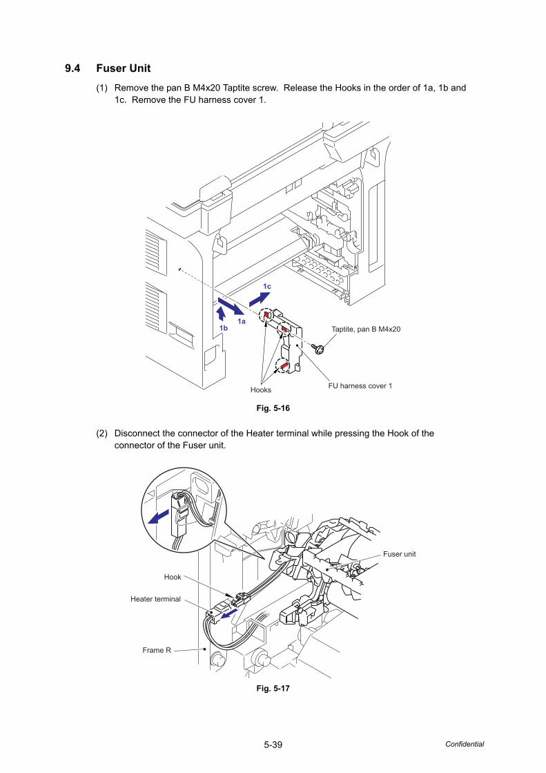
5-39 Confidential
9.4 Fuser Unit(1) Remove the pan B M4x20 Taptite screw. Release the Hooks in the order of 1a, 1b and
1c. Remove the FU harness cover 1.
Fig. 5-16
(2) Disconnect the connector of the Heater terminal while pressing the Hook of the connector of the Fuser unit.
Fig. 5-17
1b1a
1c
Hooks FU harness cover 1
Taptite, pan B M4x20
Hook
Frame R
Fuser unit
Heater terminal
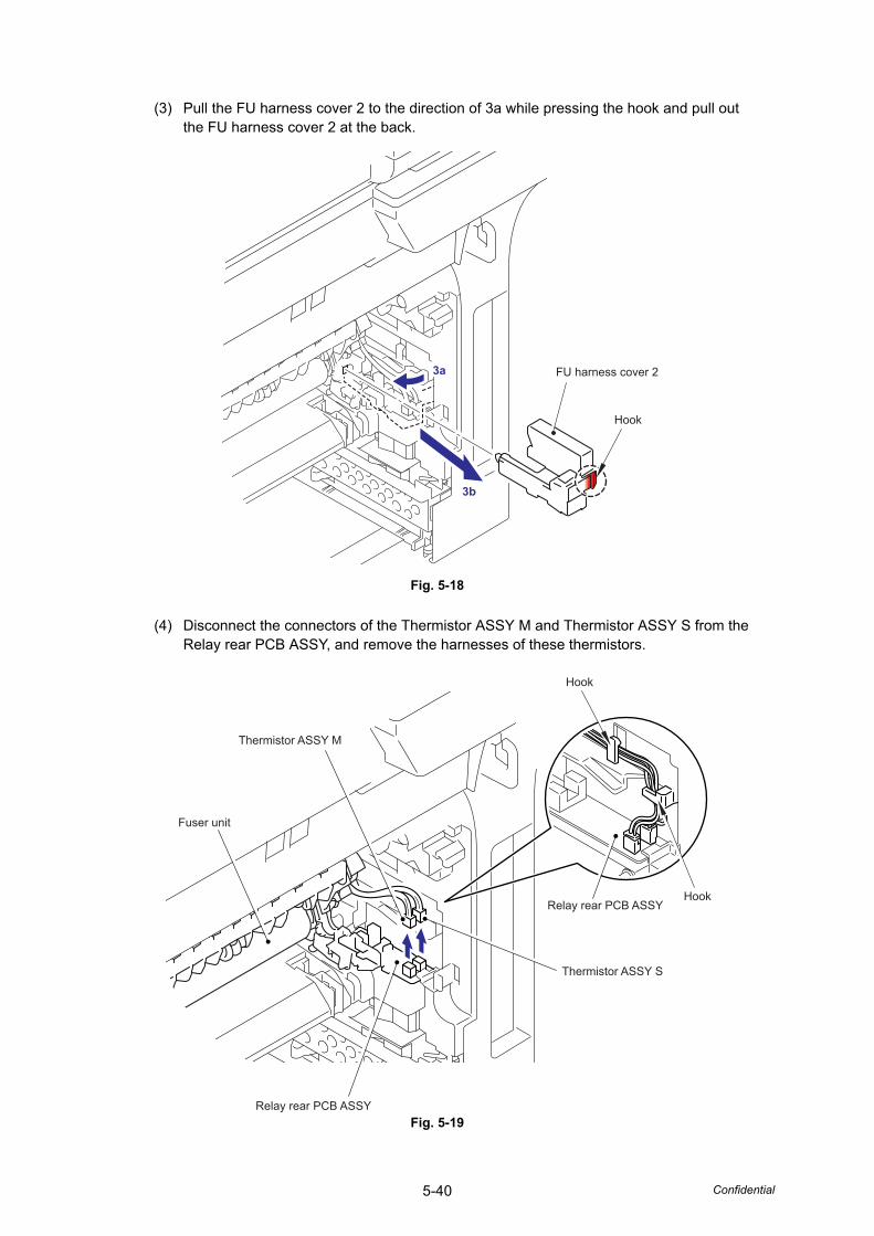
5-40 Confidential
(3) Pull the FU harness cover 2 to the direction of 3a while pressing the hook and pull out the FU harness cover 2 at the back.
Fig. 5-18
(4) Disconnect the connectors of the Thermistor ASSY M and Thermistor ASSY S from the Relay rear PCB ASSY, and remove the harnesses of these thermistors.
Fig. 5-19
Hook
FU harness cover 23a
3b
3a
3b
Thermistor ASSY S
Thermistor ASSY M
Fuser unit
Hook
Hook
Relay rear PCB ASSY
Relay rear PCB ASSY
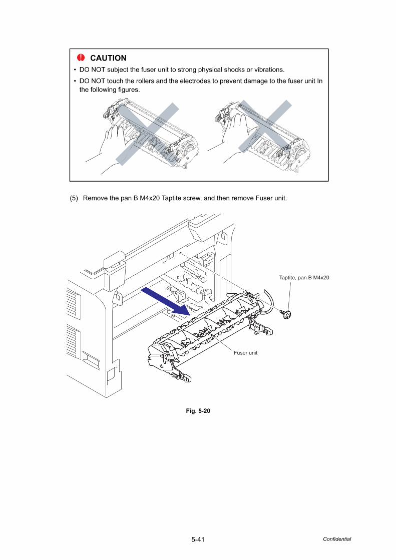
5-41 Confidential
(5) Remove the pan B M4x20 Taptite screw, and then remove Fuser unit.
Fig. 5-20
CAUTION• DO NOT subject the fuser unit to strong physical shocks or vibrations.
• DO NOT touch the rollers and the electrodes to prevent damage to the fuser unit In the following figures.
Taptite, pan B M4x20
Fuser unit
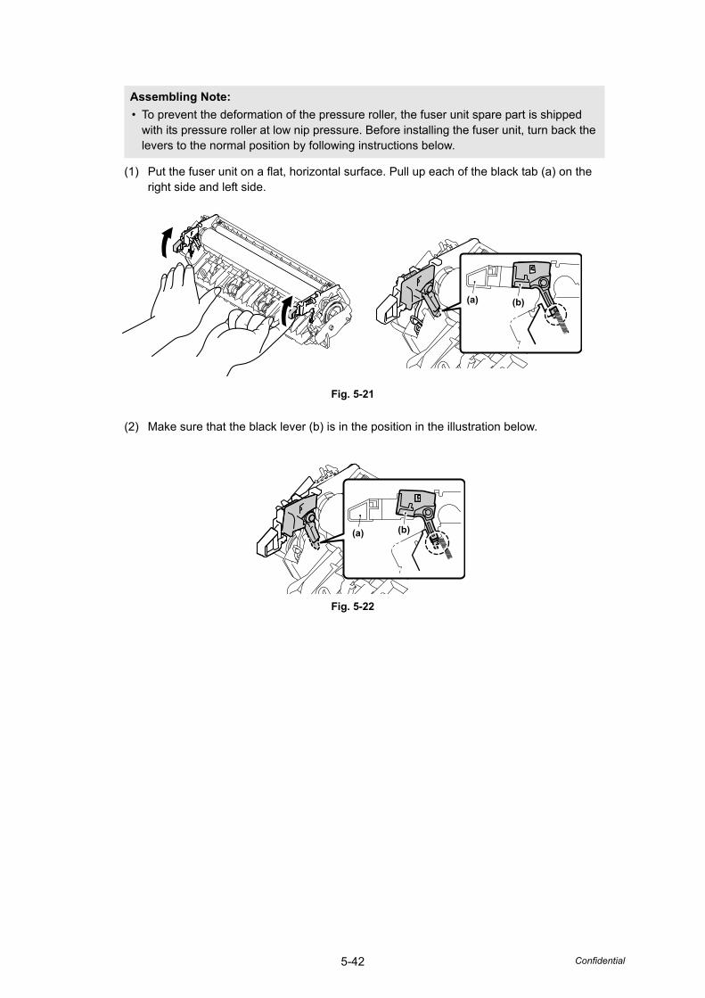
5-42 Confidential
(1) Put the fuser unit on a flat, horizontal surface. Pull up each of the black tab (a) on the right side and left side.
Fig. 5-21
(2) Make sure that the black lever (b) is in the position in the illustration below.
Fig. 5-22
Assembling Note: • To prevent the deformation of the pressure roller, the fuser unit spare part is shipped
with its pressure roller at low nip pressure. Before installing the fuser unit, turn back the levers to the normal position by following instructions below.
(a) (b)
(a) (b)
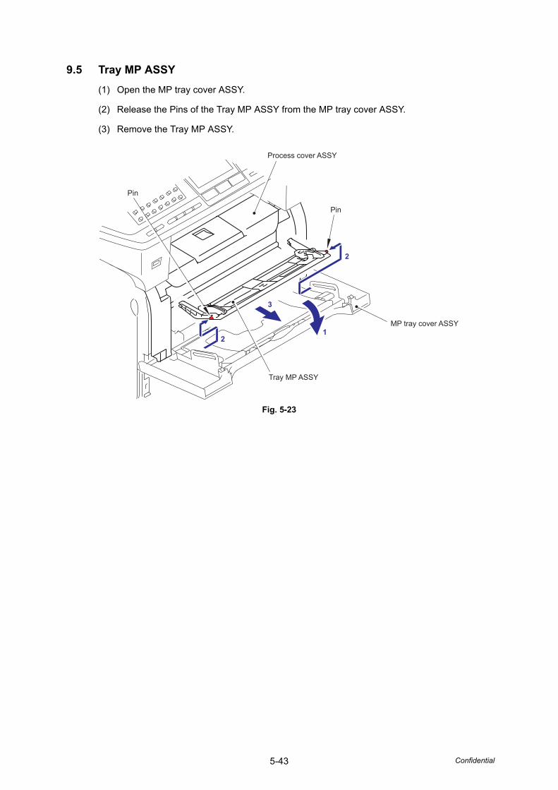
5-43 Confidential
9.5 Tray MP ASSY(1) Open the MP tray cover ASSY.
(2) Release the Pins of the Tray MP ASSY from the MP tray cover ASSY.
(3) Remove the Tray MP ASSY.
Fig. 5-23
2
2
1
3
Process cover ASSY
Pin
Tray MP ASSY
MP tray cover ASSY
Pin
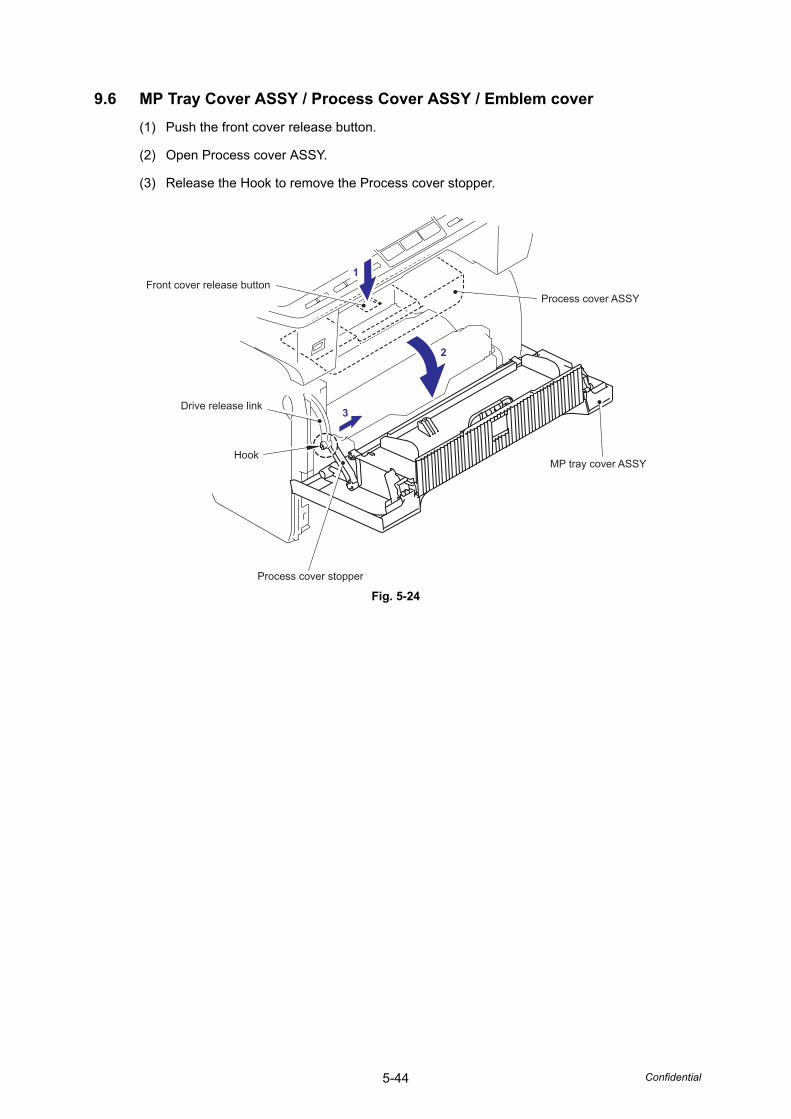
5-44 Confidential
9.6 MP Tray Cover ASSY / Process Cover ASSY / Emblem cover(1) Push the front cover release button.
(2) Open Process cover ASSY.
(3) Release the Hook to remove the Process cover stopper.
Fig. 5-24
2
1
3
Process cover ASSY
MP tray cover ASSY
Process cover stopper
Drive release link
Front cover release button
Hook
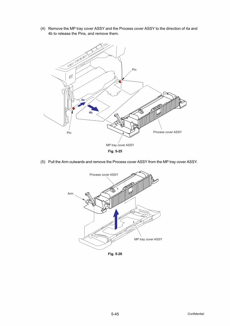
5-45 Confidential
(4) Remove the MP tray cover ASSY and the Process cover ASSY to the direction of 4a and 4b to release the Pins, and remove them.
Fig. 5-25
(5) Pull the Arm outwards and remove the Process cover ASSY from the MP tray cover ASSY.
Fig. 5-26
4b
4a
Pin
Pin Process cover ASSY
MP tray cover ASSY
Process cover ASSY
Arm
MP tray cover ASSY
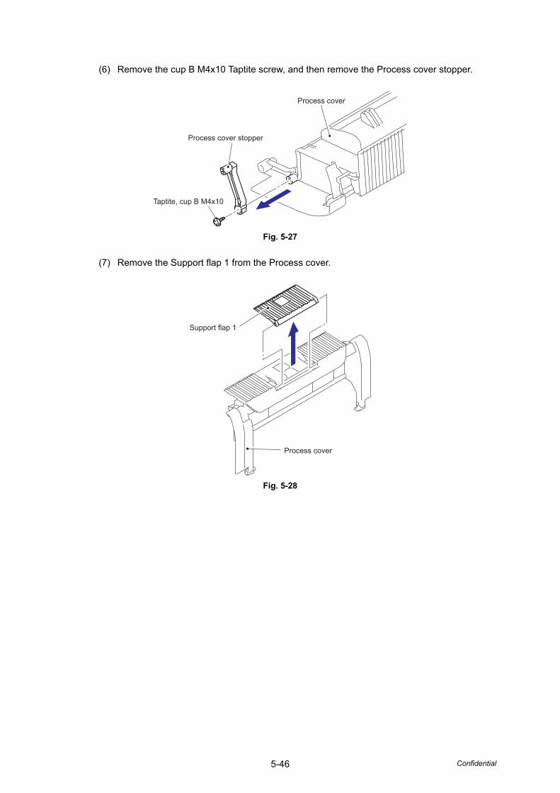
5-46 Confidential
(6) Remove the cup B M4x10 Taptite screw, and then remove the Process cover stopper.
Fig. 5-27
(7) Remove the Support flap 1 from the Process cover.
Fig. 5-28
Process cover
Process cover stopper
Taptite, cup B M4x10
Support flap 1
Process cover
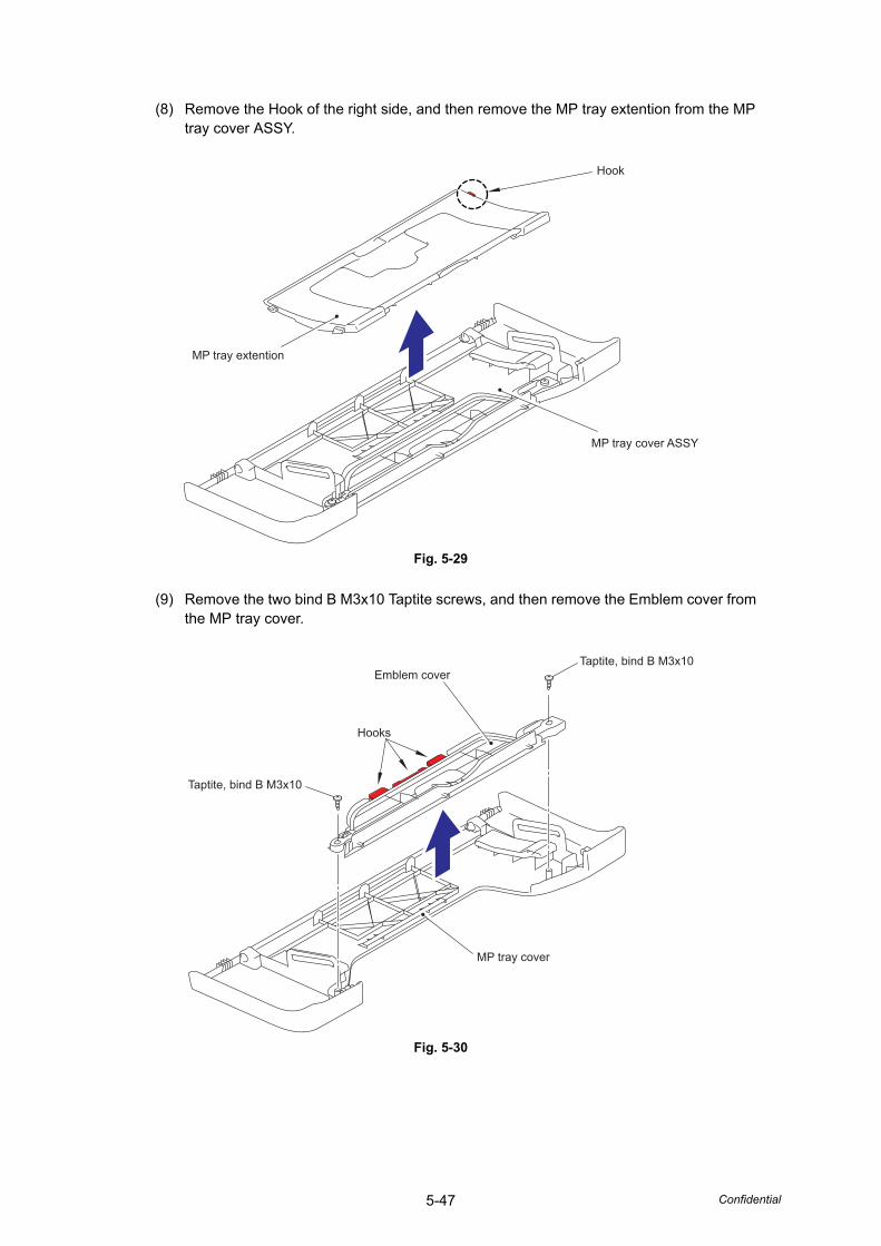
5-47 Confidential
(8) Remove the Hook of the right side, and then remove the MP tray extention from the MP tray cover ASSY.
Fig. 5-29
(9) Remove the two bind B M3x10 Taptite screws, and then remove the Emblem cover from the MP tray cover.
Fig. 5-30
MP tray cover ASSY
MP tray extention
Hook
Taptite, bind B M3x10
Taptite, bind B M3x10
MP tray cover
Emblem cover
Hooks
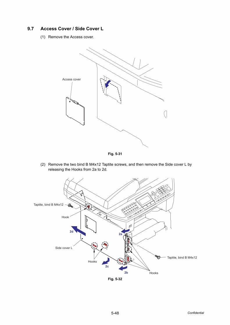
5-48 Confidential
9.7 Access Cover / Side Cover L(1) Remove the Access cover.
Fig. 5-31
(2) Remove the two bind B M4x12 Taptite screws, and then remove the Side cover L by releasing the Hooks from 2a to 2d.
Fig. 5-32
Access cover
2b
2a
2c
2d
Taptite, bind B M4x12
Hook
Hooks
Hooks
Side cover L
Taptite, bind B M4x12
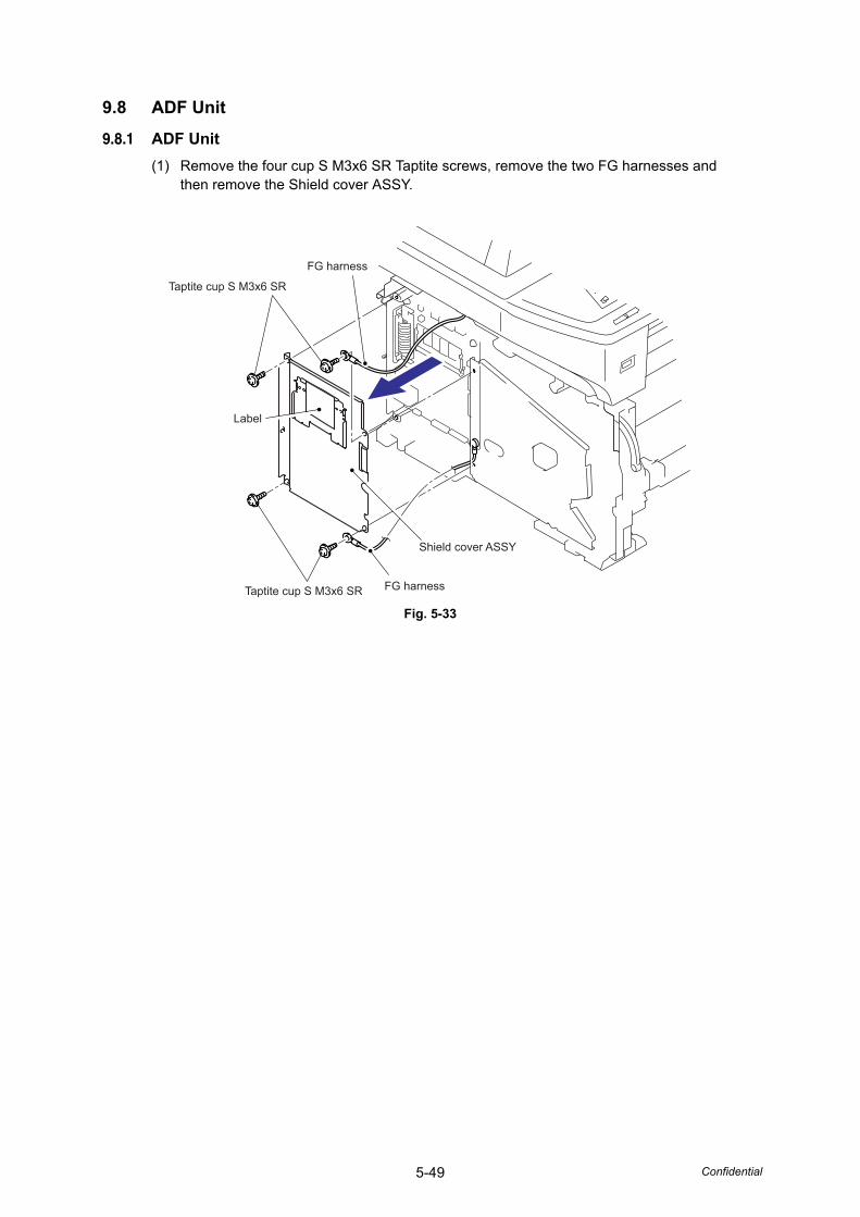
5-49 Confidential
9.8 ADF Unit
9.8.1 ADF Unit(1) Remove the four cup S M3x6 SR Taptite screws, remove the two FG harnesses and
then remove the Shield cover ASSY.
Fig. 5-33
Taptite cup S M3x6 SR
Taptite cup S M3x6 SR FG harness
FG harness
Label
Shield cover ASSY
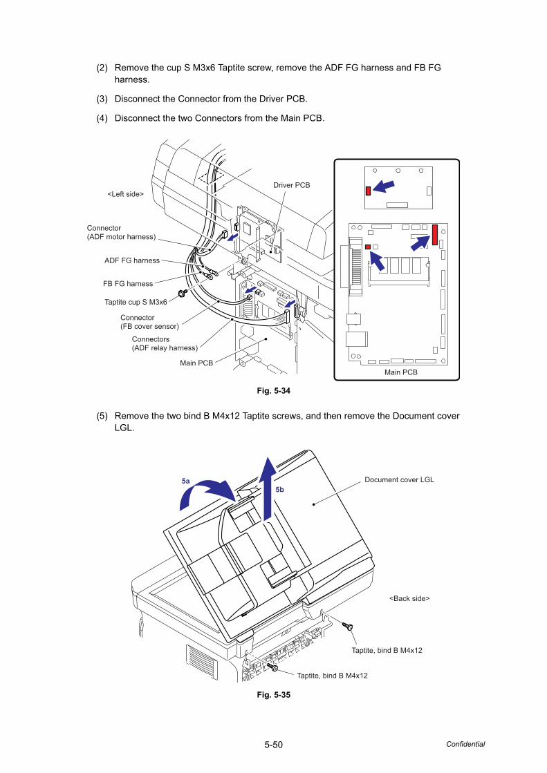
5-50 Confidential
(2) Remove the cup S M3x6 Taptite screw, remove the ADF FG harness and FB FG harness.
(3) Disconnect the Connector from the Driver PCB.
(4) Disconnect the two Connectors from the Main PCB.
Fig. 5-34
(5) Remove the two bind B M4x12 Taptite screws, and then remove the Document cover LGL.
Fig. 5-35
Driver PCB
Main PCBMain PCB
<Left side>
Connector(ADF motor harness)
Connectors(ADF relay harness)
Connector(FB cover sensor)
FB FG harness
Taptite cup S M3x6
ADF FG harness
Document cover LGL
Taptite, bind B M4x12
<Back side>
Taptite, bind B M4x12
5a5b
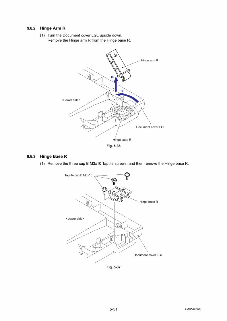
5-51 Confidential
9.8.2 Hinge Arm R(1) Turn the Document cover LGL upside down.
Remove the Hinge arm R from the Hinge base R.
Fig. 5-36
9.8.3 Hinge Base R(1) Remove the three cup B M3x10 Taptite screws, and then remove the Hinge base R.
Fig. 5-37
<Lower side>
Hinge arm R
Hinge base R
Document cover LGL
1b
1a
Taptite cup B M3x10
Hinge base R
Document cover LGL
<Lower side>
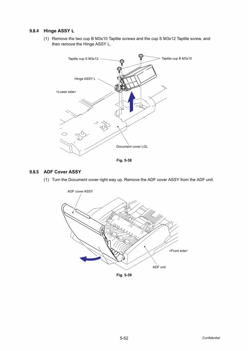
5-52 Confidential
9.8.4 Hinge ASSY L(1) Remove the two cup B M3x10 Taptite screws and the cup S M3x12 Taptite screw, and
then remove the Hinge ASSY L.
Fig. 5-38
9.8.5 ADF Cover ASSY(1) Turn the Document cover right way up. Remove the ADF cover ASSY from the ADF unit.
Fig. 5-39
Taptite cup S M3x12 Taptite cup B M3x10
Hinge ASSY L
Document cover LGL
<Lower side>
ADF cover ASSY
ADF unit
<Front side>
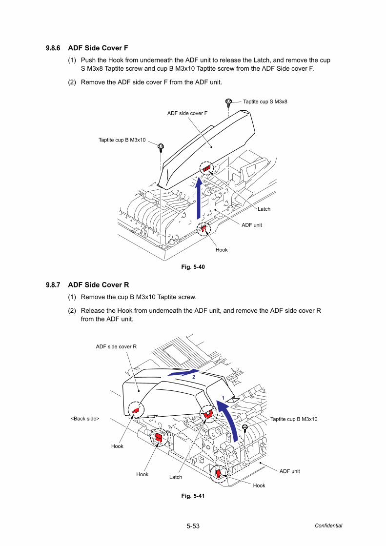
5-53 Confidential
9.8.6 ADF Side Cover F(1) Push the Hook from underneath the ADF unit to release the Latch, and remove the cup
S M3x8 Taptite screw and cup B M3x10 Taptite screw from the ADF Side cover F.
(2) Remove the ADF side cover F from the ADF unit.
Fig. 5-40
9.8.7 ADF Side Cover R(1) Remove the cup B M3x10 Taptite screw.
(2) Release the Hook from underneath the ADF unit, and remove the ADF side cover R from the ADF unit.
Fig. 5-41
Taptite cup S M3x8
Taptite cup B M3x10
ADF side cover F
ADF unit
Latch
Hook
ADF side cover R
1
2
ADF unit
Hook
Hook
Hook
<Back side>
Latch
Taptite cup B M3x10
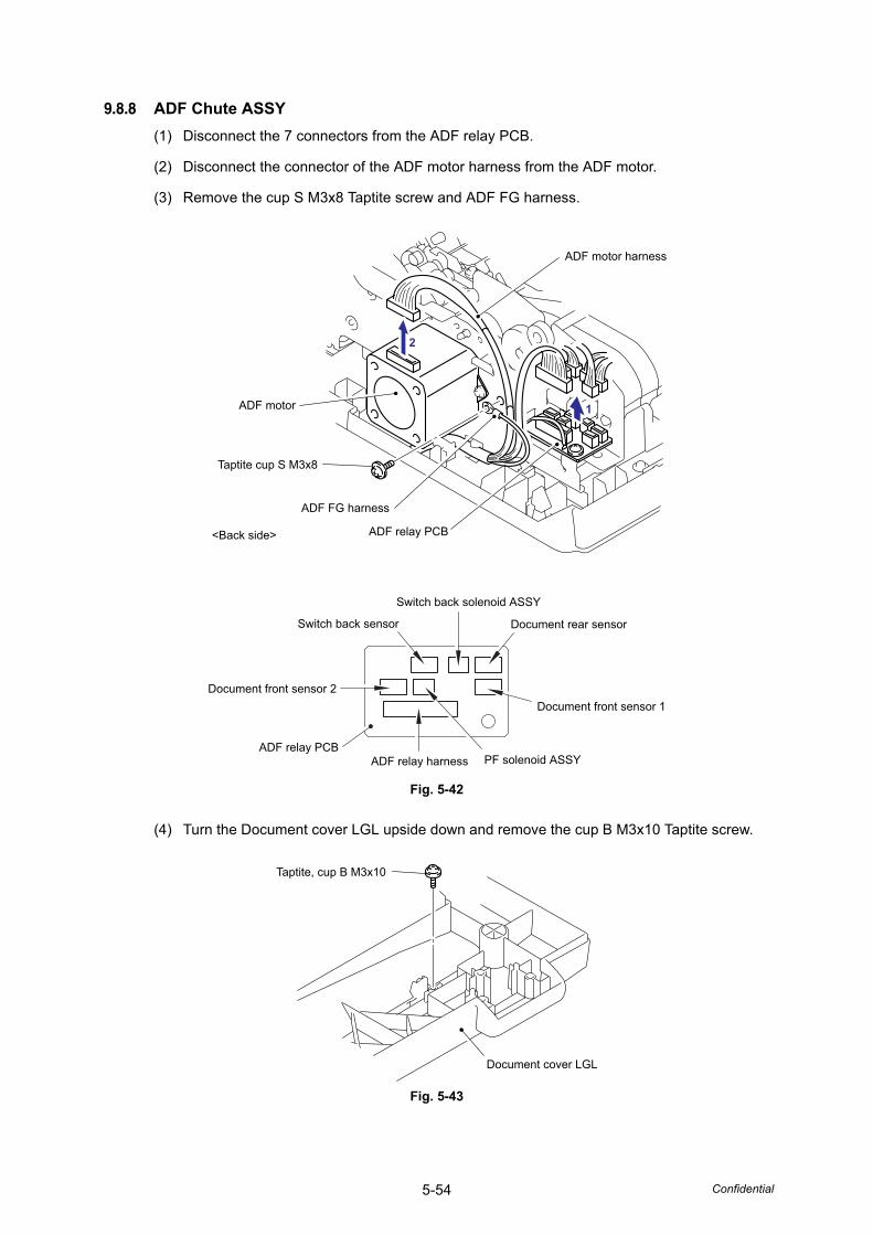
5-54 Confidential
9.8.8 ADF Chute ASSY(1) Disconnect the 7 connectors from the ADF relay PCB.
(2) Disconnect the connector of the ADF motor harness from the ADF motor.
(3) Remove the cup S M3x8 Taptite screw and ADF FG harness.
Fig. 5-42
(4) Turn the Document cover LGL upside down and remove the cup B M3x10 Taptite screw.
Fig. 5-43
ADF motor harness
ADF motor
<Back side>
1
2
ADF FG harness
ADF relay PCB
Taptite cup S M3x8
Switch back solenoid ASSY
ADF relay harness PF solenoid ASSY
Document rear sensor
Document front sensor 1
Switch back sensor
ADF relay PCB
Document front sensor 2
Taptite, cup B M3x10
Document cover LGL
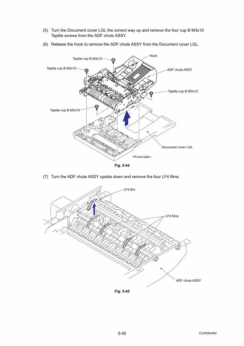
5-55 Confidential
(5) Turn the Document cover LGL the correct way up and remove the four cup B M3x10 Taptite screws from the ADF chute ASSY.
(6) Release the hook to remove the ADF chute ASSY from the Document cover LGL.
Fig. 5-44
(7) Turn the ADF chute ASSY upside down and remove the four LF4 films.
Fig. 5-45
Taptite cup B M3x10
Taptite cup B M3x10
Document cover LGL
<Front side>
ADF chute ASSY
Hook
Taptite cup B M3x10
Taptite cup B M3x10
LF4 film
LF4 films
ADF chute ASSY

5-56 Confidential
9.8.9 Sub Chute ASSY / SX Chute(1) Remove the two cup S M3x8 Taptite screws.
(2) Remove the Sub chute ASSY or SX chute from the ADF chute ASSY.
Fig. 5-46
9.8.10 Exit Chute Cover ASSY(1) Turn the ADF chute ASSY upside down and remove the four cup B M3x10 Taptite
screws.
(2) Remove the Exit chute cover ASSY from the ADF chute ASSY.
Fig. 5-47
Taptite cup S M3x8
ADF chute ASSYTaptite cup S M3x8
<Front side>
Sub chute ASSY or SX chute
Taptite cup B M3x10
Exit chute cover ASSY
ADF chute ASSY
<Front side>
Taptite cup B M3x10
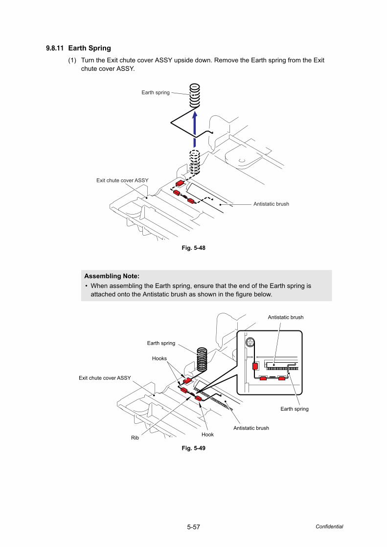
5-57 Confidential
9.8.11 Earth Spring(1) Turn the Exit chute cover ASSY upside down. Remove the Earth spring from the Exit
chute cover ASSY.
Fig. 5-48
Fig. 5-49
Assembling Note: • When assembling the Earth spring, ensure that the end of the Earth spring is
attached onto the Antistatic brush as shown in the figure below.
Earth spring
Antistatic brush
Exit chute cover ASSY
Antistatic brush
Antistatic brush
Earth spring
Earth spring
Hooks
Hook
Exit chute cover ASSY
Rib
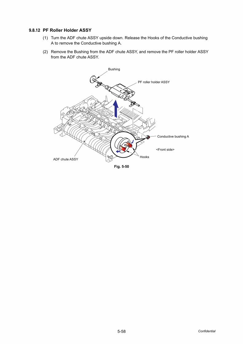
5-58 Confidential
9.8.12 PF Roller Holder ASSY(1) Turn the ADF chute ASSY upside down. Release the Hooks of the Conductive bushing
A to remove the Conductive bushing A.
(2) Remove the Bushing from the ADF chute ASSY, and remove the PF roller holder ASSY from the ADF chute ASSY.
Fig. 5-50
Bushing
PF roller holder ASSY
Conductive bushing A
<Front side>
HooksADF chute ASSY
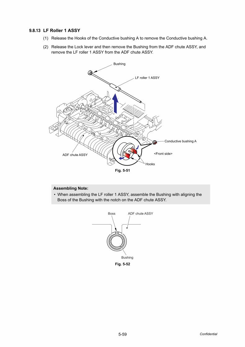
5-59 Confidential
9.8.13 LF Roller 1 ASSY(1) Release the Hooks of the Conductive bushing A to remove the Conductive bushing A.
(2) Release the Lock lever and then remove the Bushing from the ADF chute ASSY, and remove the LF roller 1 ASSY from the ADF chute ASSY.
Fig. 5-51
Fig. 5-52
Assembling Note: • When assembling the LF roller 1 ASSY, assemble the Bushing with aligning the
Boss of the Bushing with the notch on the ADF chute ASSY.
Hooks
Bushing
LF roller 1 ASSY
ADF chute ASSY
Conductive bushing A
<Front side>
Boss ADF chute ASSY
Bushing
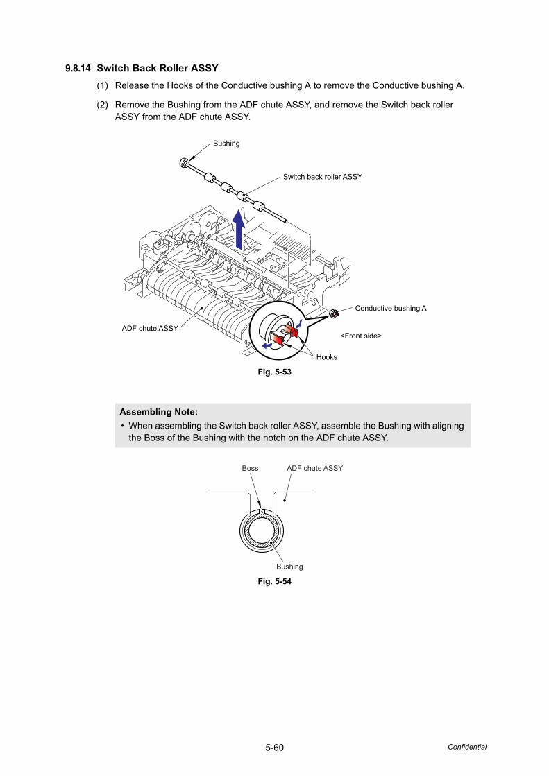
5-60 Confidential
9.8.14 Switch Back Roller ASSY(1) Release the Hooks of the Conductive bushing A to remove the Conductive bushing A.
(2) Remove the Bushing from the ADF chute ASSY, and remove the Switch back roller ASSY from the ADF chute ASSY.
Fig. 5-53
Fig. 5-54
Assembling Note: • When assembling the Switch back roller ASSY, assemble the Bushing with aligning
the Boss of the Bushing with the notch on the ADF chute ASSY.
Bushing
Switch back roller ASSY
Conductive bushing A
<Front side>
Hooks
ADF chute ASSY
Boss ADF chute ASSY
Bushing
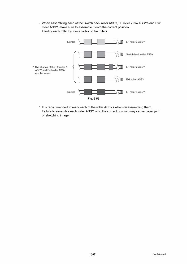
5-61 Confidential
• When assembling each of the Switch back roller ASSY, LF roller 2/3/4 ASSYs and Exit roller ASSY, make sure to assemble it onto the correct position. Identify each roller by four shades of the rollers.
Fig. 5-55
* It is recommended to mark each of the roller ASSYs when disassembling them.Failure to assemble each roller ASSY onto the correct position may cause paper jam or stretching image.
Lighter
* The shades of the LF roller 2 ASSY and Exit roller ASSY are the same.
LF roller 3 ASSY
Switch back roller ASSY
LF roller 2 ASSY
Exit roller ASSY
LF roller 4 ASSYDarker
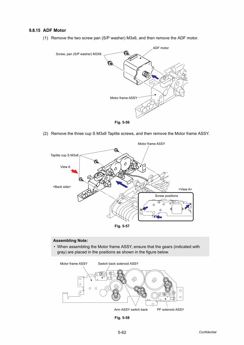
5-62 Confidential
9.8.15 ADF Motor(1) Remove the two screw pan (S/P washer) M3x6, and then remove the ADF motor.
Fig. 5-56
(2) Remove the three cup S M3x8 Taptite screws, and then remove the Motor frame ASSY.
Fig. 5-57
Fig. 5-58
Assembling Note: • When assembling the Motor frame ASSY, ensure that the gears (indicated with
gray) are placed in the positions as shown in the figure below.
Screw, pan (S/P washer) M3X6
Motor frame ASSY
ADF motor
View A
Motor frame ASSY
Taptite cup S M3x8
Screw positions
<View A><Back side>
Motor frame ASSY Switch back solenoid ASSY
PF solenoid ASSYArm ASSY switch back
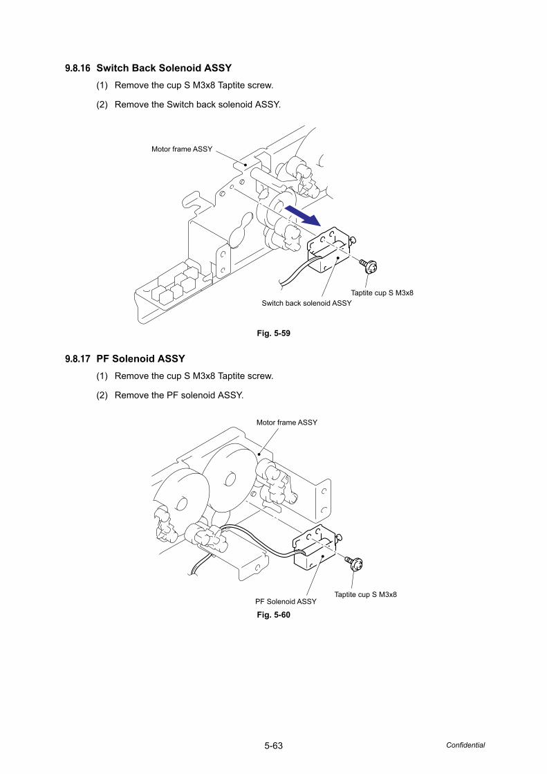
5-63 Confidential
9.8.16 Switch Back Solenoid ASSY(1) Remove the cup S M3x8 Taptite screw.
(2) Remove the Switch back solenoid ASSY.
Fig. 5-59
9.8.17 PF Solenoid ASSY(1) Remove the cup S M3x8 Taptite screw.
(2) Remove the PF solenoid ASSY.
Fig. 5-60
Motor frame ASSY
Switch back solenoid ASSYTaptite cup S M3x8
Motor frame ASSY
PF Solenoid ASSYTaptite cup S M3x8
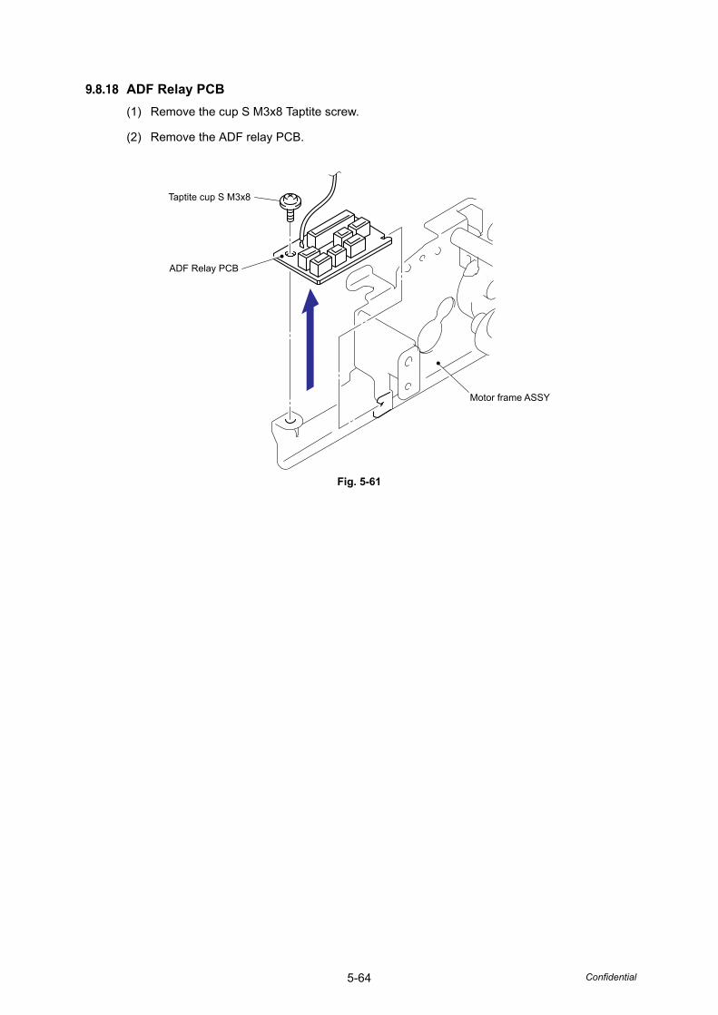
5-64 Confidential
9.8.18 ADF Relay PCB(1) Remove the cup S M3x8 Taptite screw.
(2) Remove the ADF relay PCB.
Fig. 5-61
ADF Relay PCB
Motor frame ASSY
Taptite cup S M3x8
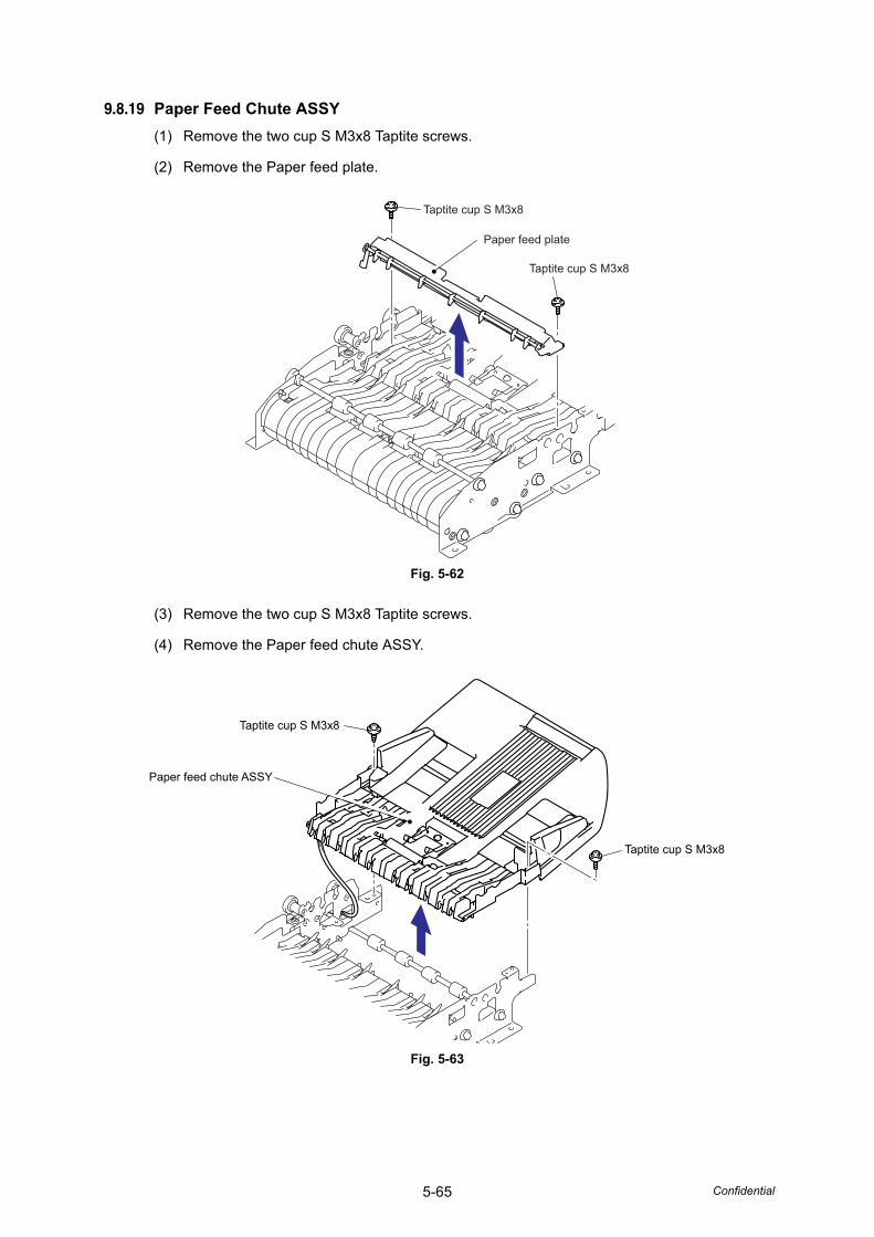
5-65 Confidential
9.8.19 Paper Feed Chute ASSY(1) Remove the two cup S M3x8 Taptite screws.
(2) Remove the Paper feed plate.
Fig. 5-62
(3) Remove the two cup S M3x8 Taptite screws.
(4) Remove the Paper feed chute ASSY.
Fig. 5-63
Taptite cup S M3x8
Taptite cup S M3x8
Paper feed plate
Taptite cup S M3x8
Taptite cup S M3x8
Paper feed chute ASSY
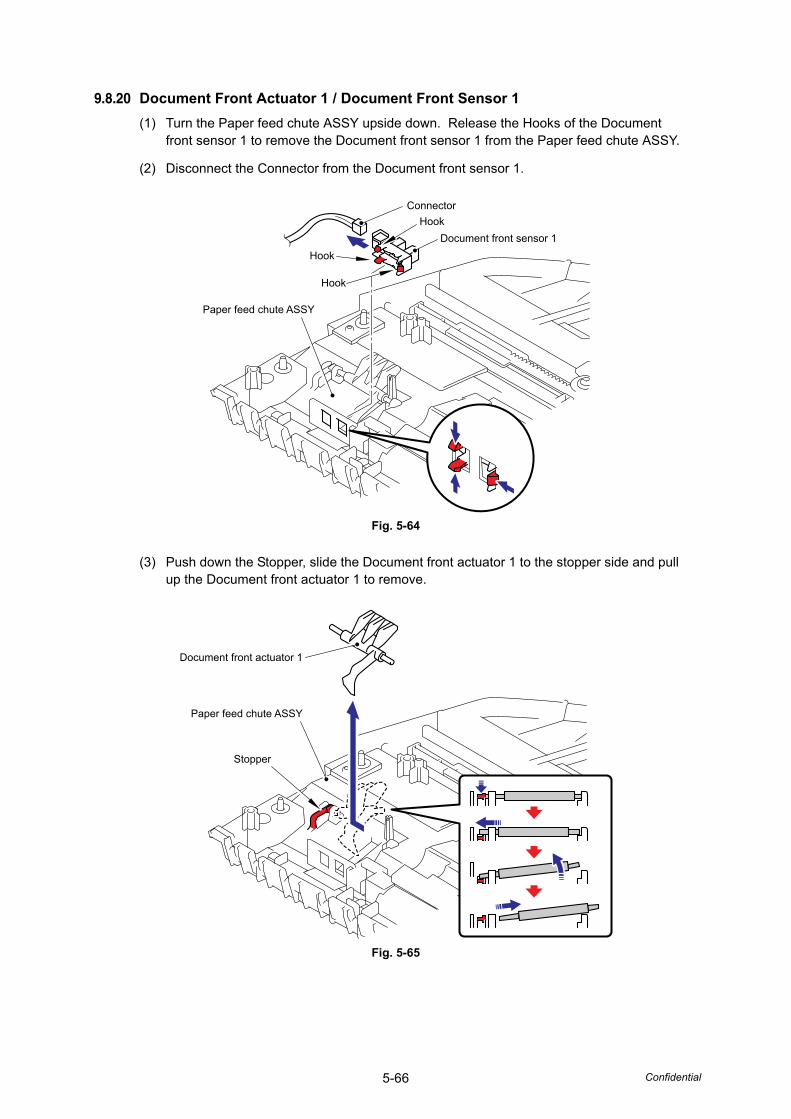
5-66 Confidential
9.8.20 Document Front Actuator 1 / Document Front Sensor 1(1) Turn the Paper feed chute ASSY upside down. Release the Hooks of the Document
front sensor 1 to remove the Document front sensor 1 from the Paper feed chute ASSY.
(2) Disconnect the Connector from the Document front sensor 1.
Fig. 5-64
(3) Push down the Stopper, slide the Document front actuator 1 to the stopper side and pull up the Document front actuator 1 to remove.
Fig. 5-65
ConnectorHook
Hook
Hook
Paper feed chute ASSY
Document front sensor 1
Document front actuator 1
Paper feed chute ASSY
Stopper
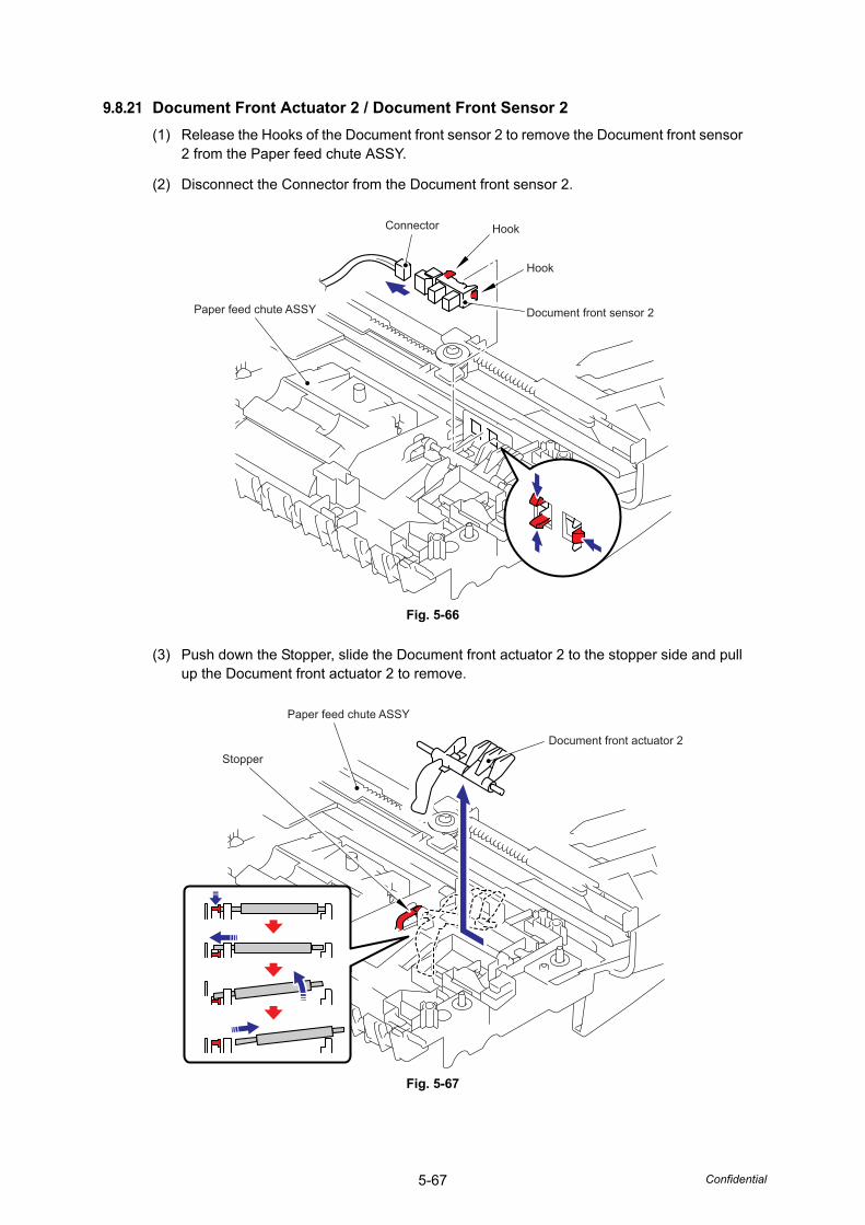
5-67 Confidential
9.8.21 Document Front Actuator 2 / Document Front Sensor 2(1) Release the Hooks of the Document front sensor 2 to remove the Document front sensor
2 from the Paper feed chute ASSY.
(2) Disconnect the Connector from the Document front sensor 2.
Fig. 5-66
(3) Push down the Stopper, slide the Document front actuator 2 to the stopper side and pull up the Document front actuator 2 to remove.
Fig. 5-67
Connector
Paper feed chute ASSY
Hook
Hook
Document front sensor 2
Stopper
Paper feed chute ASSY
Document front actuator 2
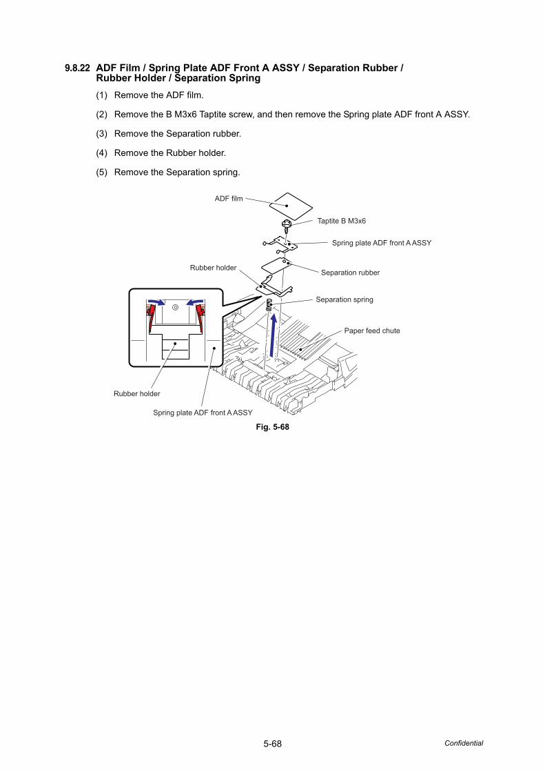
5-68 Confidential
9.8.22 ADF Film / Spring Plate ADF Front A ASSY / Separation Rubber /Rubber Holder / Separation Spring(1) Remove the ADF film.
(2) Remove the B M3x6 Taptite screw, and then remove the Spring plate ADF front A ASSY.
(3) Remove the Separation rubber.
(4) Remove the Rubber holder.
(5) Remove the Separation spring.
Fig. 5-68
ADF film
Rubber holder
Rubber holder
Taptite B M3x6
Spring plate ADF front A ASSY
Spring plate ADF front A ASSY
Separation rubber
Separation spring
Paper feed chute
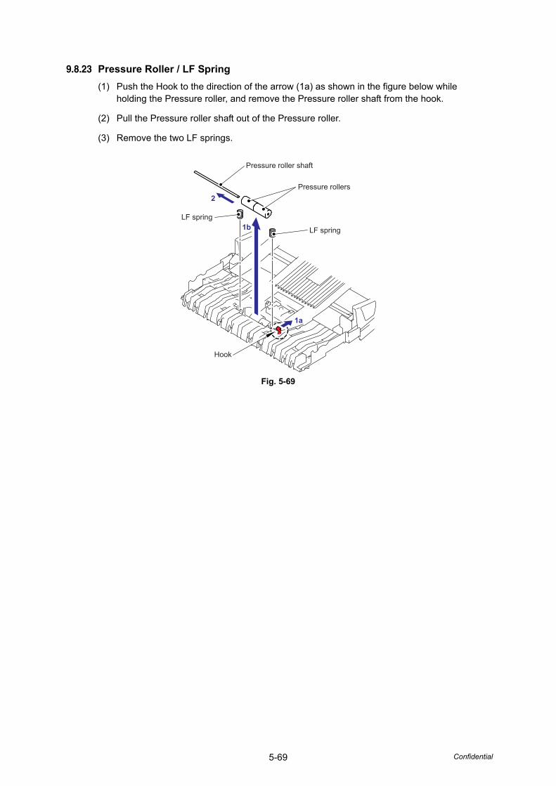
5-69 Confidential
9.8.23 Pressure Roller / LF Spring(1) Push the Hook to the direction of the arrow (1a) as shown in the figure below while
holding the Pressure roller, and remove the Pressure roller shaft from the hook.
(2) Pull the Pressure roller shaft out of the Pressure roller.
(3) Remove the two LF springs.
Fig. 5-69
Pressure roller shaft
Pressure rollers
LF spring
LF spring
Hook
2
1a
1b
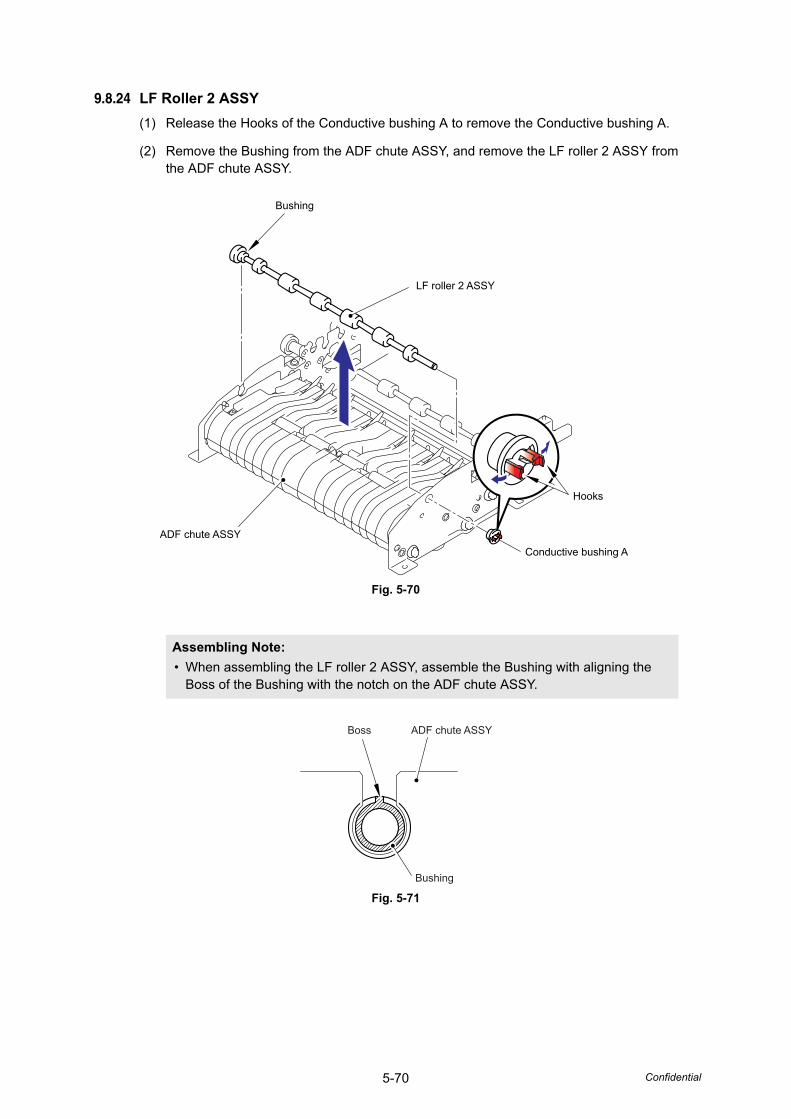
5-70 Confidential
9.8.24 LF Roller 2 ASSY(1) Release the Hooks of the Conductive bushing A to remove the Conductive bushing A.
(2) Remove the Bushing from the ADF chute ASSY, and remove the LF roller 2 ASSY from the ADF chute ASSY.
Fig. 5-70
Fig. 5-71
Assembling Note: • When assembling the LF roller 2 ASSY, assemble the Bushing with aligning the
Boss of the Bushing with the notch on the ADF chute ASSY.
Bushing
LF roller 2 ASSY
Hooks
Conductive bushing AADF chute ASSY
Boss ADF chute ASSY
Bushing
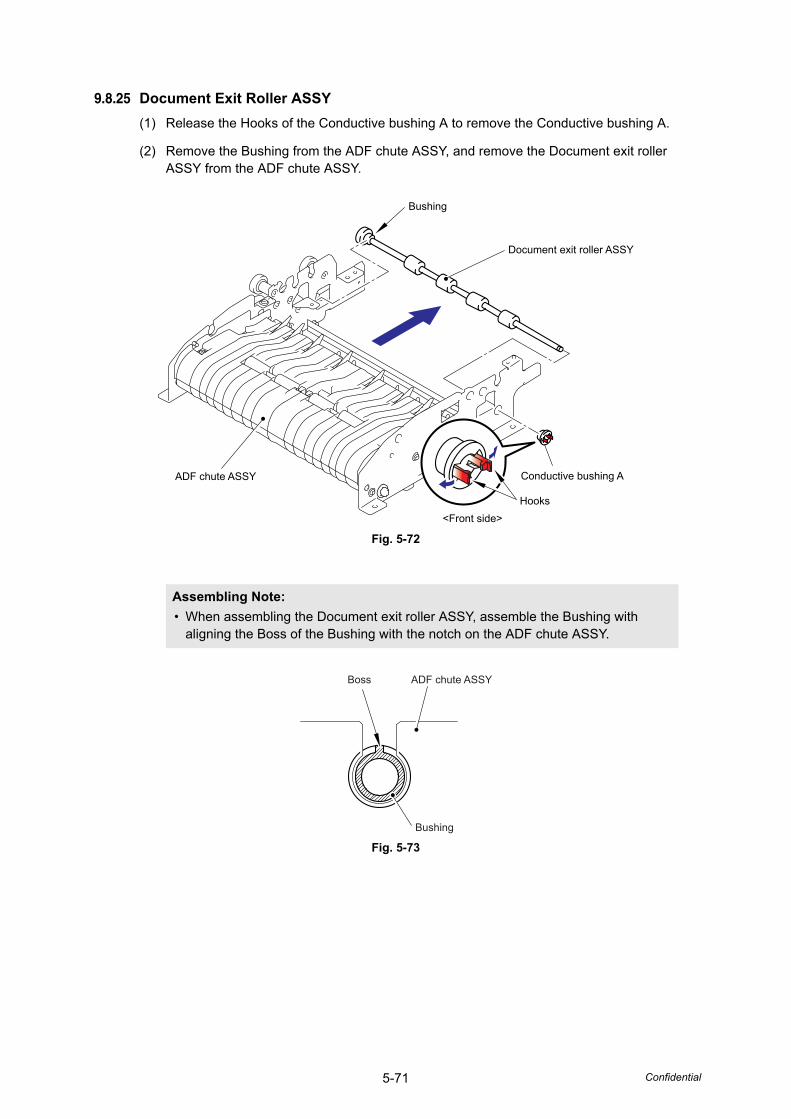
5-71 Confidential
9.8.25 Document Exit Roller ASSY(1) Release the Hooks of the Conductive bushing A to remove the Conductive bushing A.
(2) Remove the Bushing from the ADF chute ASSY, and remove the Document exit roller ASSY from the ADF chute ASSY.
Fig. 5-72
Fig. 5-73
Assembling Note: • When assembling the Document exit roller ASSY, assemble the Bushing with
aligning the Boss of the Bushing with the notch on the ADF chute ASSY.
Bushing
Document exit roller ASSY
Conductive bushing A
Hooks<Front side>
ADF chute ASSY
Boss ADF chute ASSY
Bushing
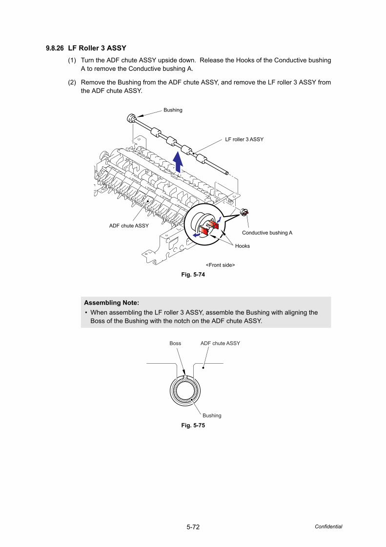
5-72 Confidential
9.8.26 LF Roller 3 ASSY(1) Turn the ADF chute ASSY upside down. Release the Hooks of the Conductive bushing
A to remove the Conductive bushing A.
(2) Remove the Bushing from the ADF chute ASSY, and remove the LF roller 3 ASSY from the ADF chute ASSY.
Fig. 5-74
Fig. 5-75
Assembling Note: • When assembling the LF roller 3 ASSY, assemble the Bushing with aligning the
Boss of the Bushing with the notch on the ADF chute ASSY.
Bushing
LF roller 3 ASSY
ADF chute ASSYConductive bushing A
Hooks
<Front side>
Boss ADF chute ASSY
Bushing
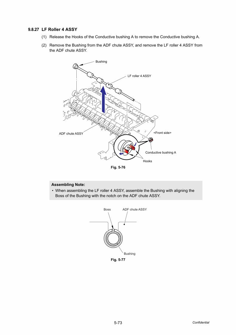
5-73 Confidential
9.8.27 LF Roller 4 ASSY(1) Release the Hooks of the Conductive bushing A to remove the Conductive bushing A.
(2) Remove the Bushing from the ADF chute ASSY, and remove the LF roller 4 ASSY from the ADF chute ASSY.
Fig. 5-76
Fig. 5-77
Assembling Note: • When assembling the LF roller 4 ASSY, assemble the Bushing with aligning the
Boss of the Bushing with the notch on the ADF chute ASSY.
Bushing
LF roller 4 ASSY
Conductive bushing A
<Front side>
Hooks
ADF chute ASSY
Boss ADF chute ASSY
Bushing
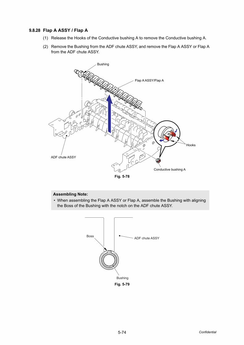
5-74 Confidential
9.8.28 Flap A ASSY / Flap A(1) Release the Hooks of the Conductive bushing A to remove the Conductive bushing A.
(2) Remove the Bushing from the ADF chute ASSY, and remove the Flap A ASSY or Flap A from the ADF chute ASSY.
Fig. 5-78
Fig. 5-79
Assembling Note: • When assembling the Flap A ASSY or Flap A, assemble the Bushing with aligning
the Boss of the Bushing with the notch on the ADF chute ASSY.
Bushing
Flap A ASSY/Flap A
Hooks
Conductive bushing A
ADF chute ASSY
ADF chute ASSYBoss
Bushing
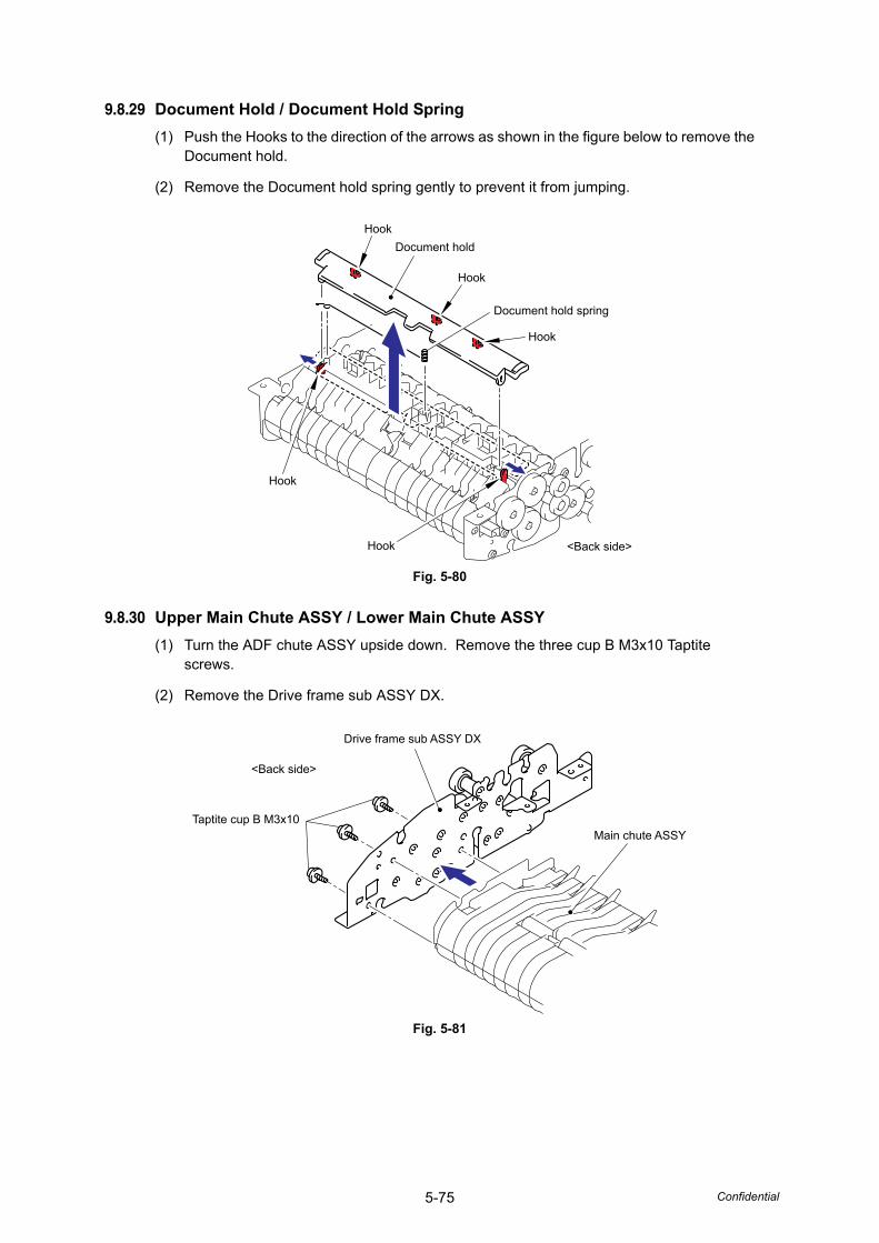
5-75 Confidential
9.8.29 Document Hold / Document Hold Spring(1) Push the Hooks to the direction of the arrows as shown in the figure below to remove the
Document hold.
(2) Remove the Document hold spring gently to prevent it from jumping.
Fig. 5-80
9.8.30 Upper Main Chute ASSY / Lower Main Chute ASSY(1) Turn the ADF chute ASSY upside down. Remove the three cup B M3x10 Taptite
screws.
(2) Remove the Drive frame sub ASSY DX.
Fig. 5-81
Hook
Hook
Document hold
Document hold spring
Hook
<Back side>
Hook
Hook
Drive frame sub ASSY DX
Taptite cup B M3x10
<Back side>
Main chute ASSY
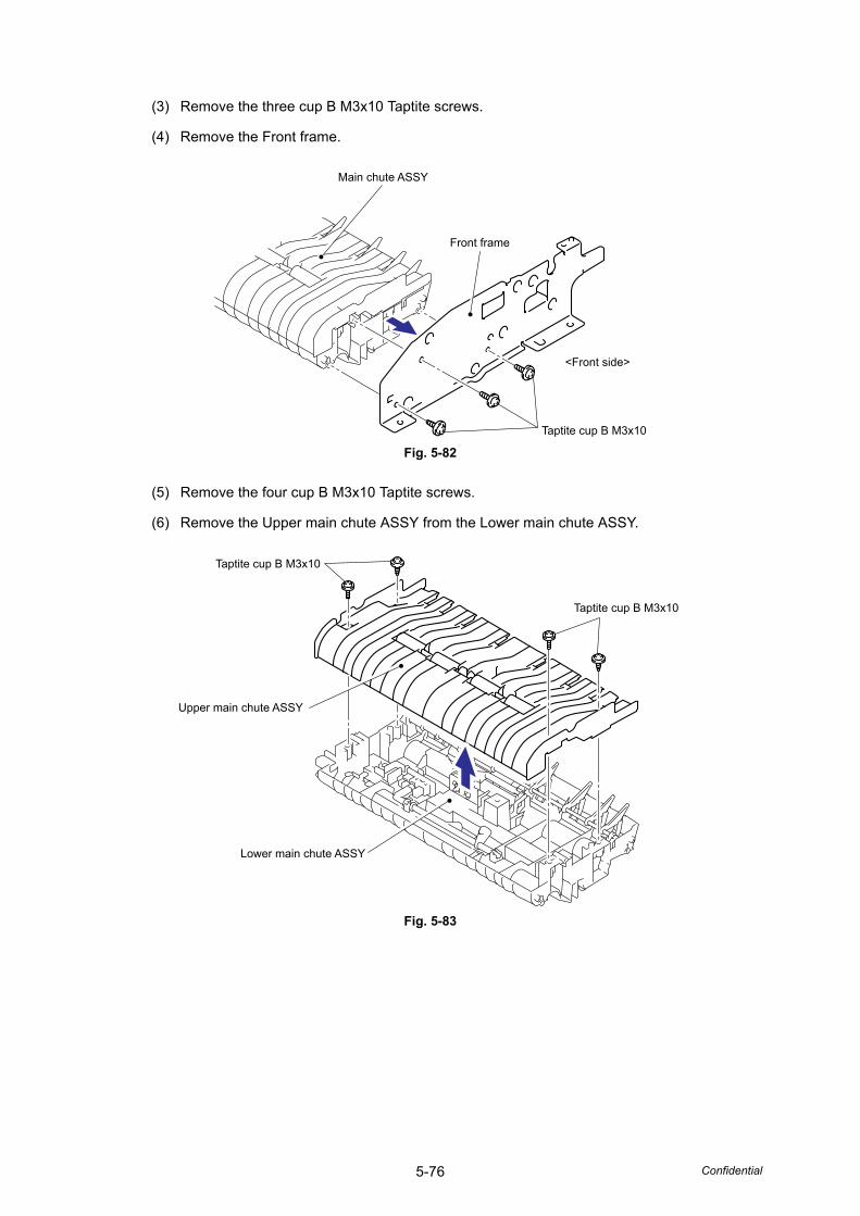
5-76 Confidential
(3) Remove the three cup B M3x10 Taptite screws.
(4) Remove the Front frame.
Fig. 5-82
(5) Remove the four cup B M3x10 Taptite screws.
(6) Remove the Upper main chute ASSY from the Lower main chute ASSY.
Fig. 5-83
Taptite cup B M3x10
Front frame
Main chute ASSY
<Front side>
Taptite cup B M3x10
Taptite cup B M3x10
Upper main chute ASSY
Lower main chute ASSY
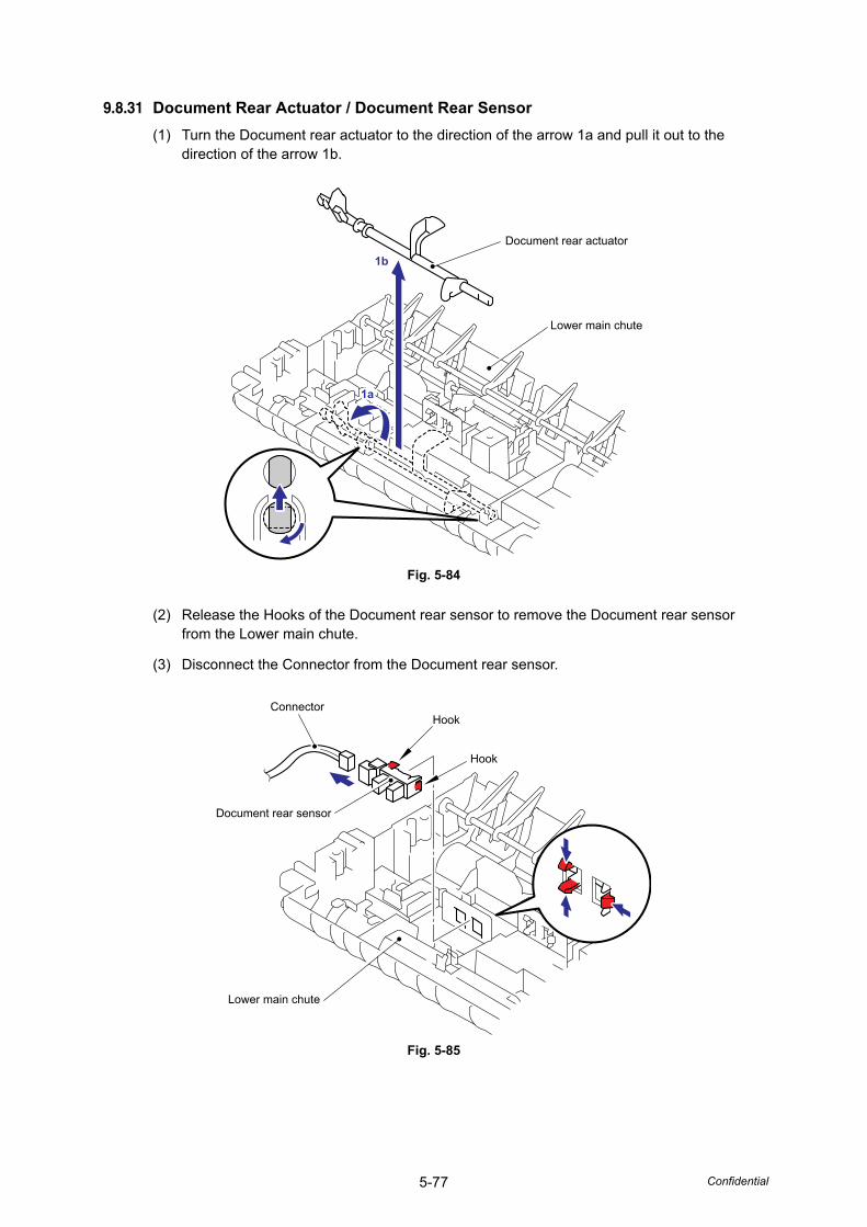
5-77 Confidential
9.8.31 Document Rear Actuator / Document Rear Sensor(1) Turn the Document rear actuator to the direction of the arrow 1a and pull it out to the
direction of the arrow 1b.
Fig. 5-84
(2) Release the Hooks of the Document rear sensor to remove the Document rear sensor from the Lower main chute.
(3) Disconnect the Connector from the Document rear sensor.
Fig. 5-85
Document rear actuator
Lower main chute
1b
1a1a
ConnectorHook
Hook
Document rear sensor
Lower main chute
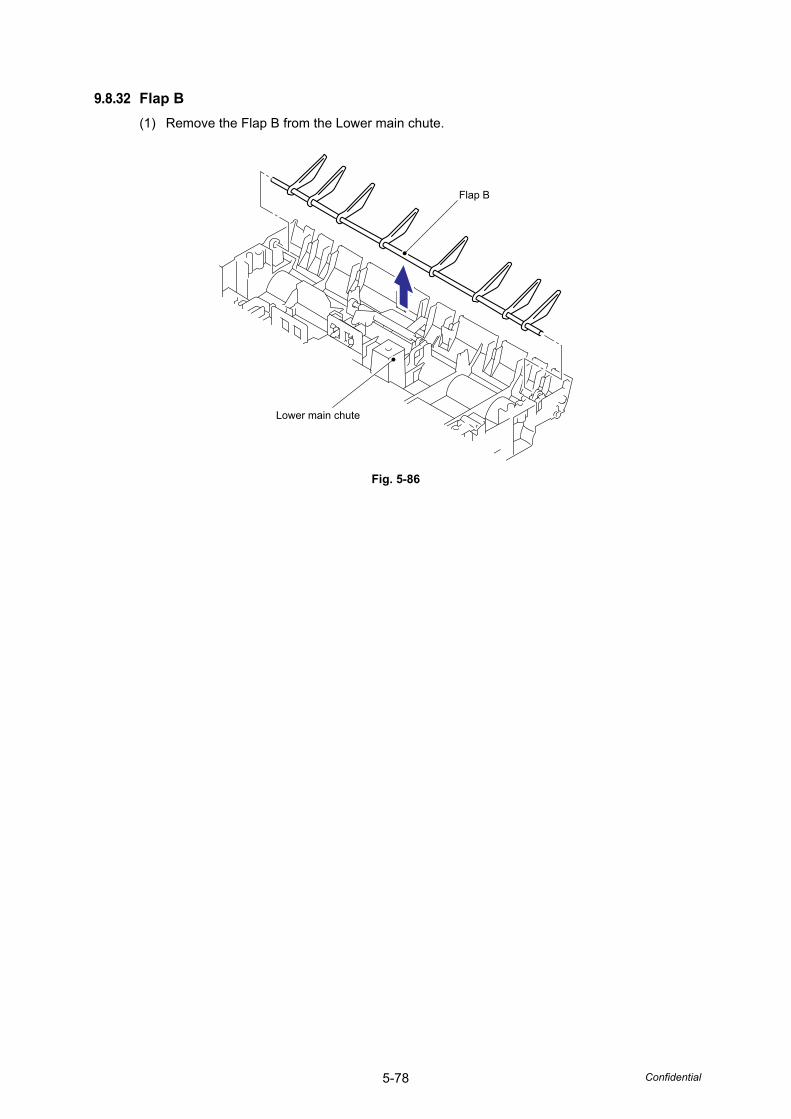
5-78 Confidential
9.8.32 Flap B(1) Remove the Flap B from the Lower main chute.
Fig. 5-86
Flap B
Lower main chute
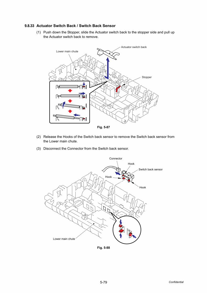
5-79 Confidential
9.8.33 Actuator Switch Back / Switch Back Sensor(1) Push down the Stopper, slide the Actuator switch back to the stopper side and pull up
the Actuator switch back to remove.
Fig. 5-87
(2) Release the Hooks of the Switch back sensor to remove the Switch back sensor from the Lower main chute.
(3) Disconnect the Connector from the Switch back sensor.
Fig. 5-88
Lower main chuteActuator switch back
Stopper
Connector
Hook
Hook
Switch back sensor
Lower main chute
Hook
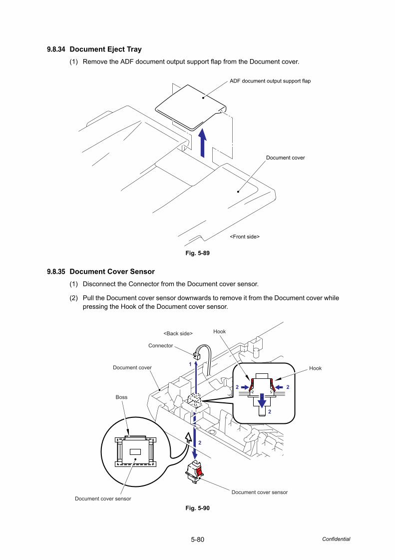
5-80 Confidential
9.8.34 Document Eject Tray(1) Remove the ADF document output support flap from the Document cover.
Fig. 5-89
9.8.35 Document Cover Sensor(1) Disconnect the Connector from the Document cover sensor.
(2) Pull the Document cover sensor downwards to remove it from the Document cover while pressing the Hook of the Document cover sensor.
Fig. 5-90
ADF document output support flap
Document cover
<Front side>
Hook
Hook
Connector
Document cover
Boss
Document cover sensorDocument cover sensor
2 2
2
2
1
<Back side>
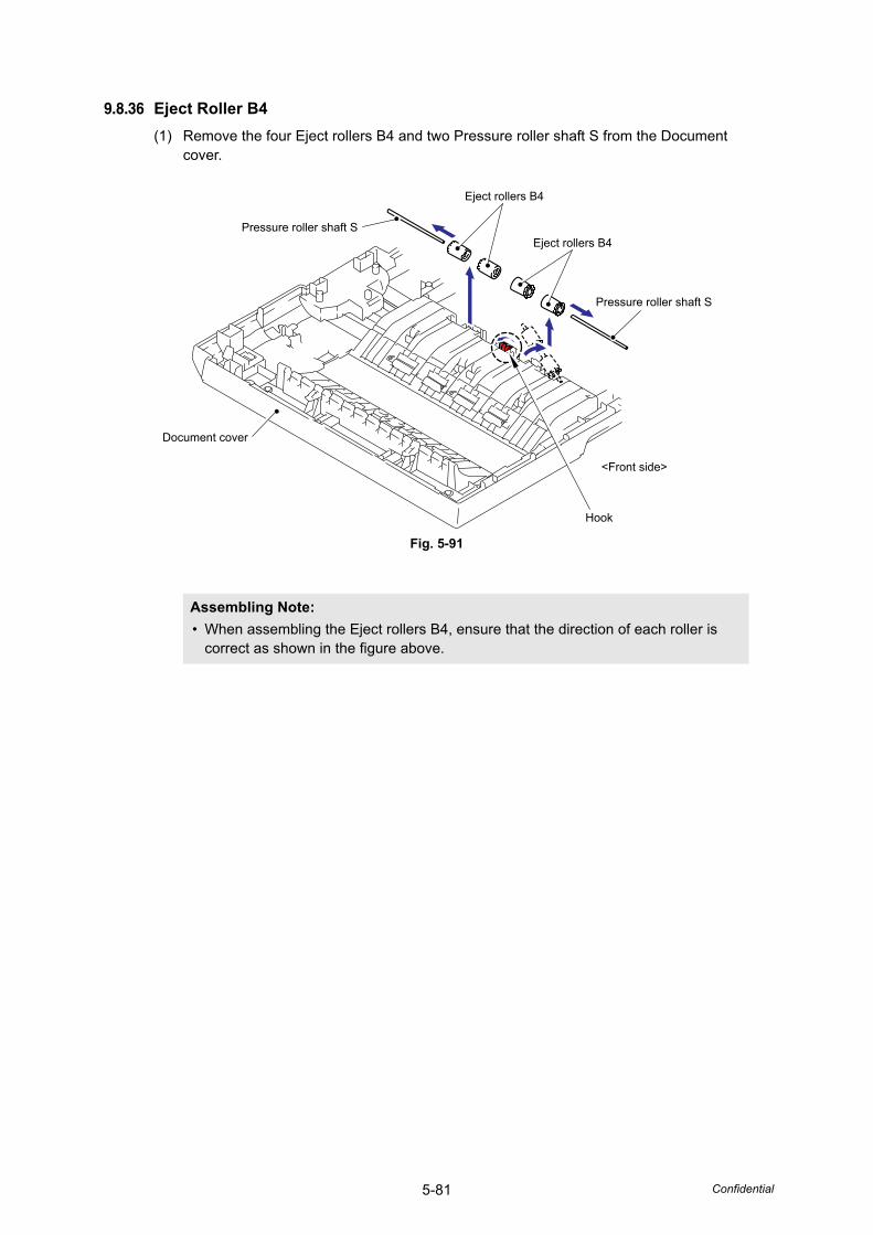
5-81 Confidential
9.8.36 Eject Roller B4(1) Remove the four Eject rollers B4 and two Pressure roller shaft S from the Document
cover.
Fig. 5-91
Assembling Note: • When assembling the Eject rollers B4, ensure that the direction of each roller is
correct as shown in the figure above.
Eject rollers B4
Eject rollers B4
Pressure roller shaft S
Hook
<Front side>
Pressure roller shaft S
Document cover
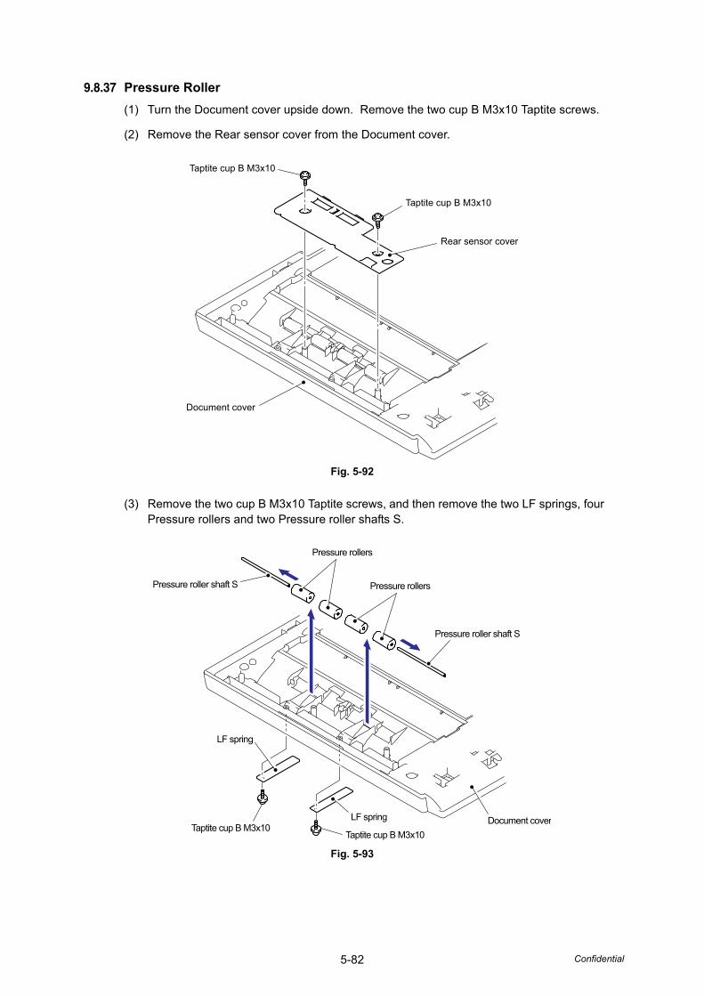
5-82 Confidential
9.8.37 Pressure Roller(1) Turn the Document cover upside down. Remove the two cup B M3x10 Taptite screws.
(2) Remove the Rear sensor cover from the Document cover.
Fig. 5-92
(3) Remove the two cup B M3x10 Taptite screws, and then remove the two LF springs, four Pressure rollers and two Pressure roller shafts S.
Fig. 5-93
Taptite cup B M3x10
Taptite cup B M3x10
Document cover
Rear sensor cover
Pressure rollers
Pressure rollers
Pressure roller shaft S
Document coverTaptite cup B M3x10
LF spring
LF spring
Taptite cup B M3x10
Pressure roller shaft S
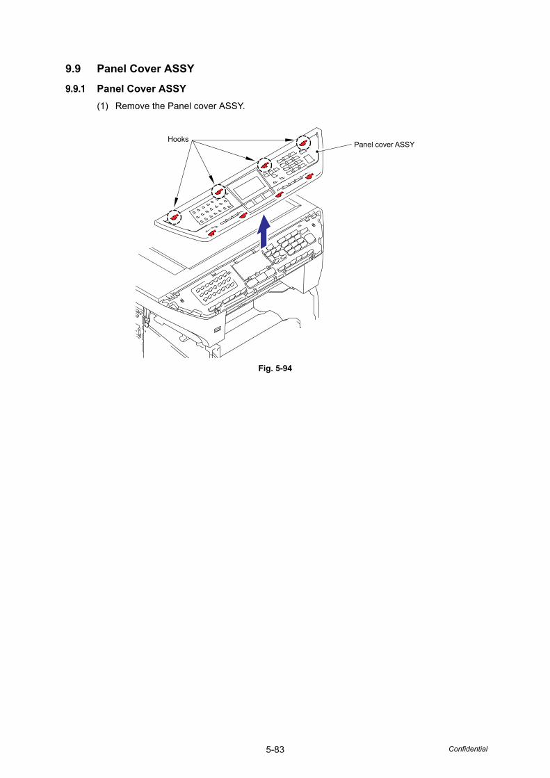
5-83 Confidential
9.9 Panel Cover ASSY
9.9.1 Panel Cover ASSY(1) Remove the Panel cover ASSY.
Fig. 5-94
HooksPanel cover ASSY
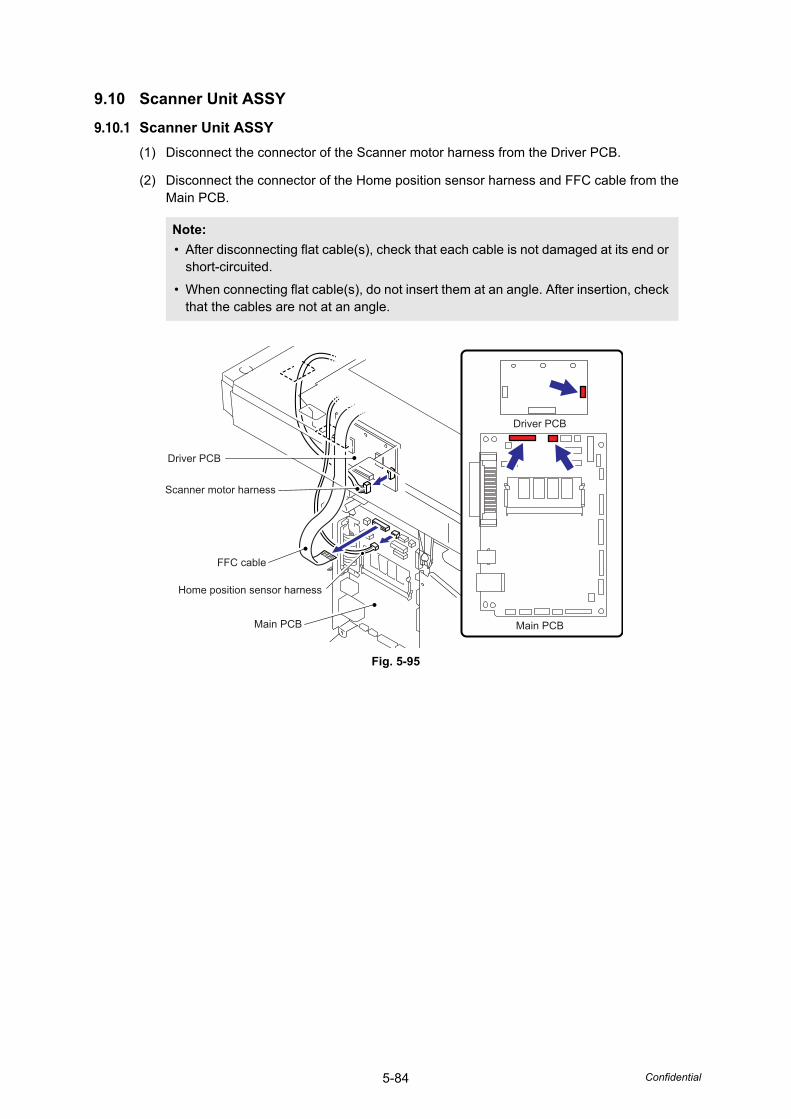
5-84 Confidential
9.10 Scanner Unit ASSY
9.10.1 Scanner Unit ASSY(1) Disconnect the connector of the Scanner motor harness from the Driver PCB.
(2) Disconnect the connector of the Home position sensor harness and FFC cable from the Main PCB.
Fig. 5-95
Note: • After disconnecting flat cable(s), check that each cable is not damaged at its end or
short-circuited.
• When connecting flat cable(s), do not insert them at an angle. After insertion, check that the cables are not at an angle.
Driver PCB
Driver PCB
Scanner motor harness
Main PCB Main PCB
FFC cable
Home position sensor harness
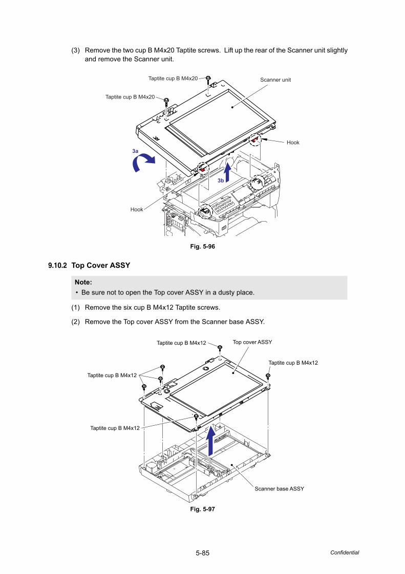
5-85 Confidential
(3) Remove the two cup B M4x20 Taptite screws. Lift up the rear of the Scanner unit slightly and remove the Scanner unit.
Fig. 5-96
9.10.2 Top Cover ASSY
(1) Remove the six cup B M4x12 Taptite screws.
(2) Remove the Top cover ASSY from the Scanner base ASSY.
Fig. 5-97
Note: • Be sure not to open the Top cover ASSY in a dusty place.
3a
3b
Scanner unitTaptite cup B M4x20
Taptite cup B M4x20
Hook
Hook
Taptite cup B M4x12
Taptite cup B M4x12
Top cover ASSY
Scanner base ASSY
Taptite cup B M4x12
Taptite cup B M4x12
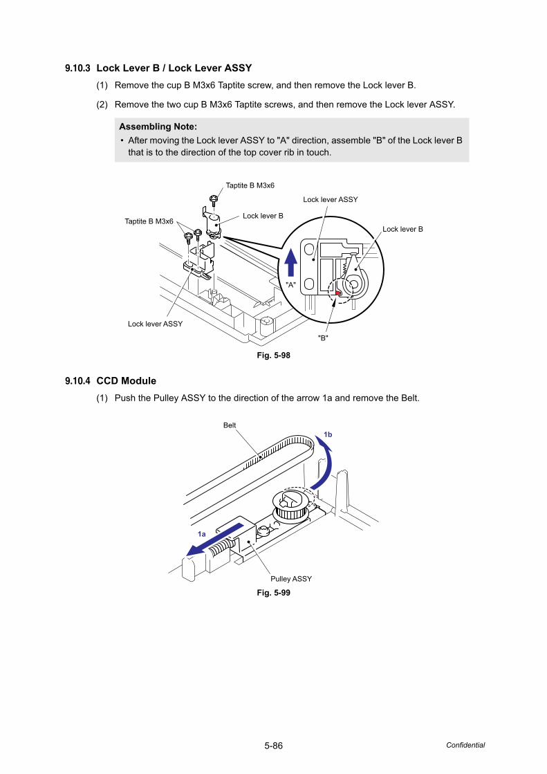
5-86 Confidential
9.10.3 Lock Lever B / Lock Lever ASSY(1) Remove the cup B M3x6 Taptite screw, and then remove the Lock lever B.
(2) Remove the two cup B M3x6 Taptite screws, and then remove the Lock lever ASSY.
Fig. 5-98
9.10.4 CCD Module(1) Push the Pulley ASSY to the direction of the arrow 1a and remove the Belt.
Fig. 5-99
Assembling Note: • After moving the Lock lever ASSY to "A" direction, assemble "B" of the Lock lever B
that is to the direction of the top cover rib in touch.
Taptite B M3x6
Taptite B M3x6
Lock lever ASSY
Lock lever ASSY
Lock lever B
Lock lever B
"A"
"B"
Belt
1a
1b
Pulley ASSY
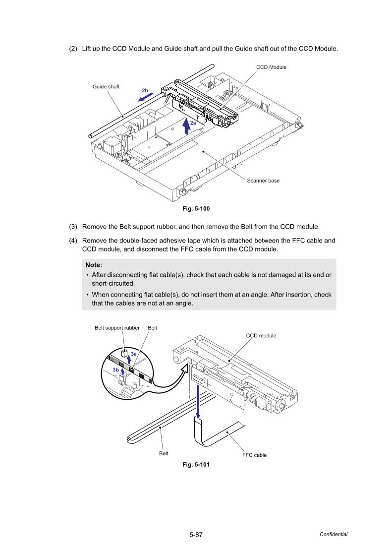
5-87 Confidential
(2) Lift up the CCD Module and Guide shaft and pull the Guide shaft out of the CCD Module.
Fig. 5-100
(3) Remove the Belt support rubber, and then remove the Belt from the CCD module.
(4) Remove the double-faced adhesive tape which is attached between the FFC cable and CCD module, and disconnect the FFC cable from the CCD module.
Fig. 5-101
Note: • After disconnecting flat cable(s), check that each cable is not damaged at its end or
short-circuited.
• When connecting flat cable(s), do not insert them at an angle. After insertion, check that the cables are not at an angle.
2b
2a
Guide shaft
CCD Module
Scanner base
Belt support rubber
3a
3b
Belt
Belt
CCD module
FFC cable
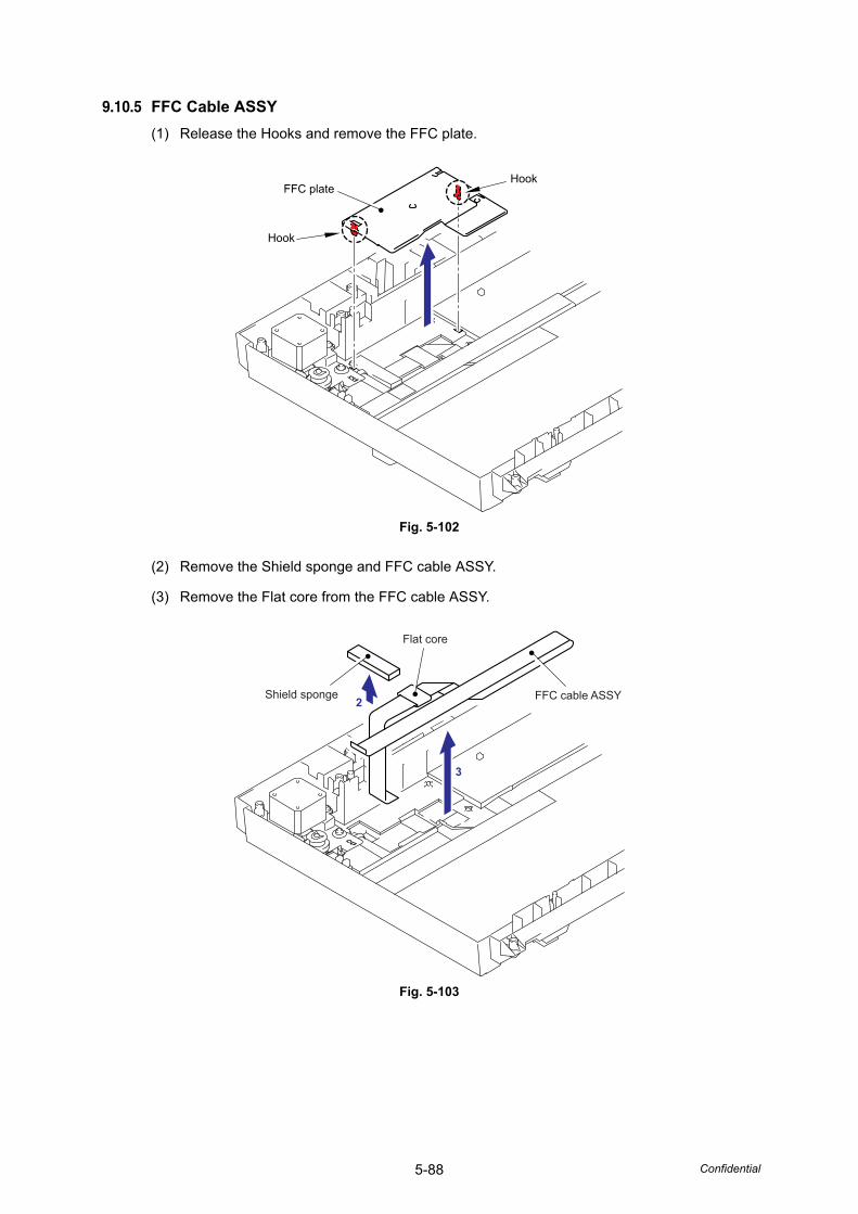
5-88 Confidential
9.10.5 FFC Cable ASSY(1) Release the Hooks and remove the FFC plate.
Fig. 5-102
(2) Remove the Shield sponge and FFC cable ASSY.
(3) Remove the Flat core from the FFC cable ASSY.
Fig. 5-103
Hook
Hook
FFC plate
2
3
Shield sponge
Flat core
FFC cable ASSY
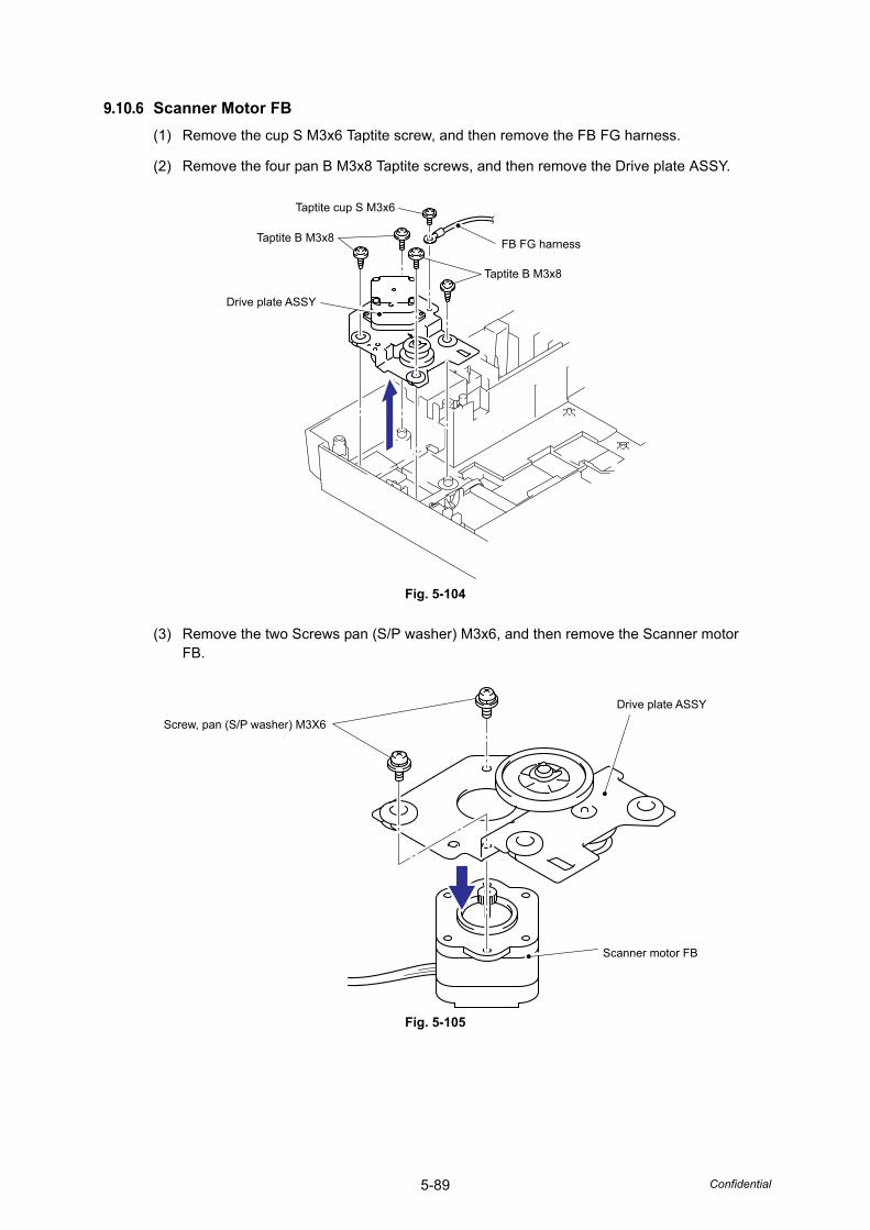
5-89 Confidential
9.10.6 Scanner Motor FB(1) Remove the cup S M3x6 Taptite screw, and then remove the FB FG harness.
(2) Remove the four pan B M3x8 Taptite screws, and then remove the Drive plate ASSY.
Fig. 5-104
(3) Remove the two Screws pan (S/P washer) M3x6, and then remove the Scanner motor FB.
Fig. 5-105
Taptite cup S M3x6
Taptite B M3x8
Drive plate ASSY
Taptite B M3x8
FB FG harness
Drive plate ASSY
Screw, pan (S/P washer) M3X6
Scanner motor FB
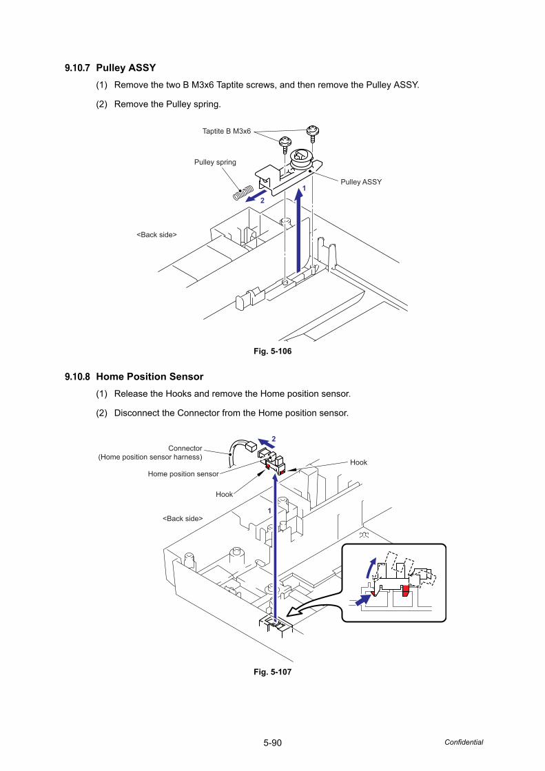
5-90 Confidential
9.10.7 Pulley ASSY(1) Remove the two B M3x6 Taptite screws, and then remove the Pulley ASSY.
(2) Remove the Pulley spring.
Fig. 5-106
9.10.8 Home Position Sensor(1) Release the Hooks and remove the Home position sensor.
(2) Disconnect the Connector from the Home position sensor.
Fig. 5-107
Pulley ASSY
Pulley spring
12
<Back side>
Taptite B M3x6
2
1
Connector(Home position sensor harness)
Home position sensor
Hook
Hook
<Back side>
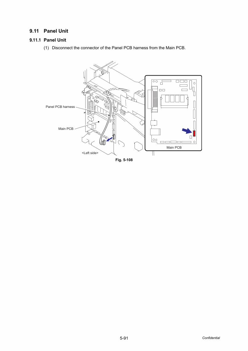
5-91 Confidential
9.11 Panel Unit
9.11.1 Panel Unit(1) Disconnect the connector of the Panel PCB harness from the Main PCB.
Fig. 5-108
Main PCB<Left side>
Main PCB
Panel PCB harness
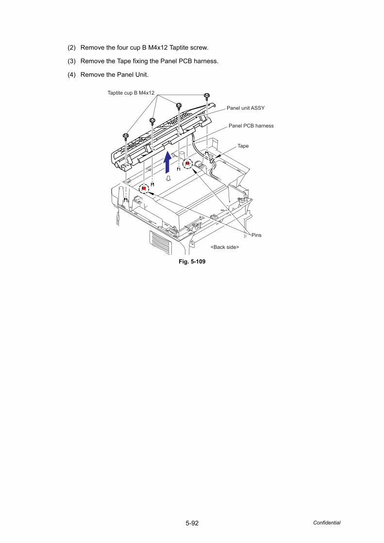
5-92 Confidential
(2) Remove the four cup B M4x12 Taptite screw.
(3) Remove the Tape fixing the Panel PCB harness.
(4) Remove the Panel Unit.
Fig. 5-109
Tape
Pins
Panel unit ASSY
Panel PCB harness
<Back side>
Taptite cup B M4x12
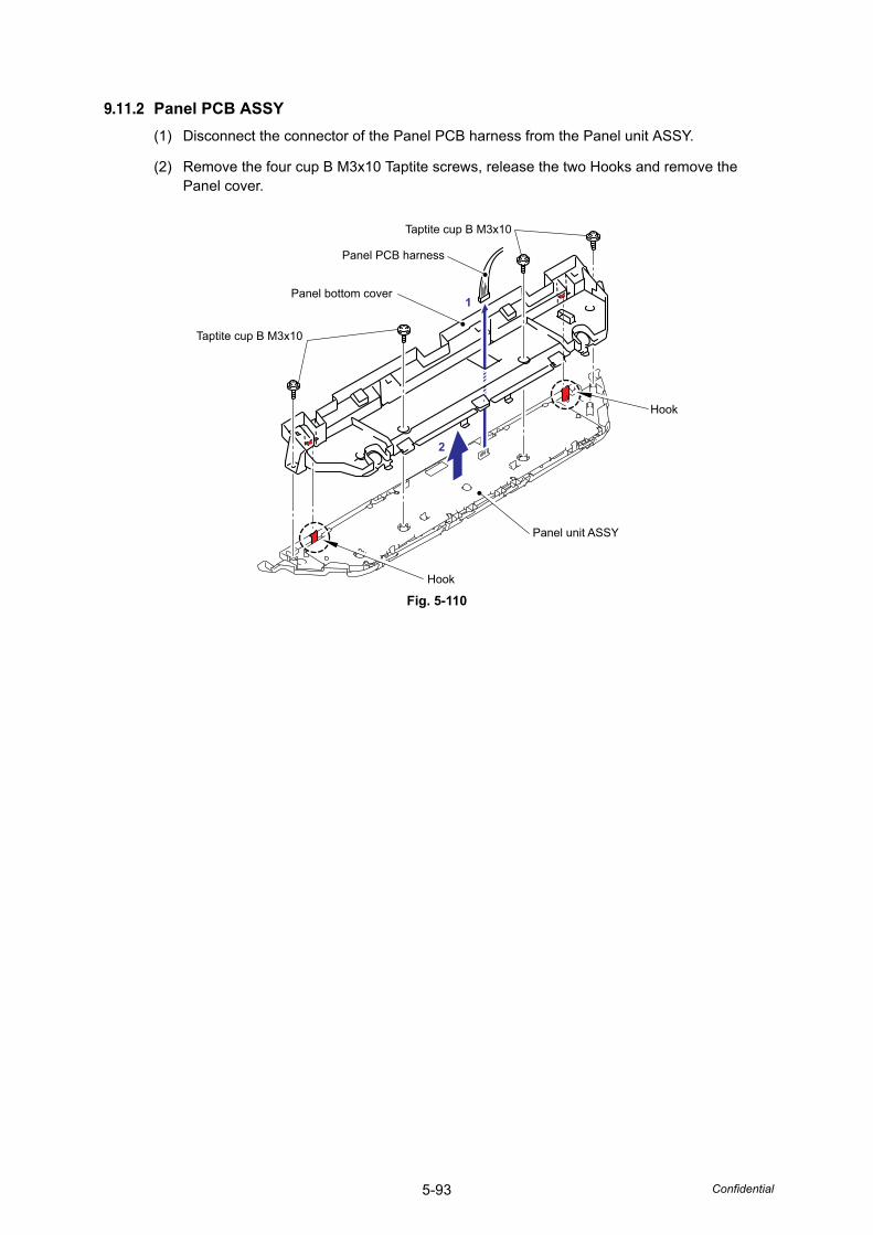
5-93 Confidential
9.11.2 Panel PCB ASSY(1) Disconnect the connector of the Panel PCB harness from the Panel unit ASSY.
(2) Remove the four cup B M3x10 Taptite screws, release the two Hooks and remove the Panel cover.
Fig. 5-110Hook
Hook
Panel unit ASSY
Panel PCB harness
Taptite cup B M3x10
Panel bottom cover
Taptite cup B M3x10
1
2
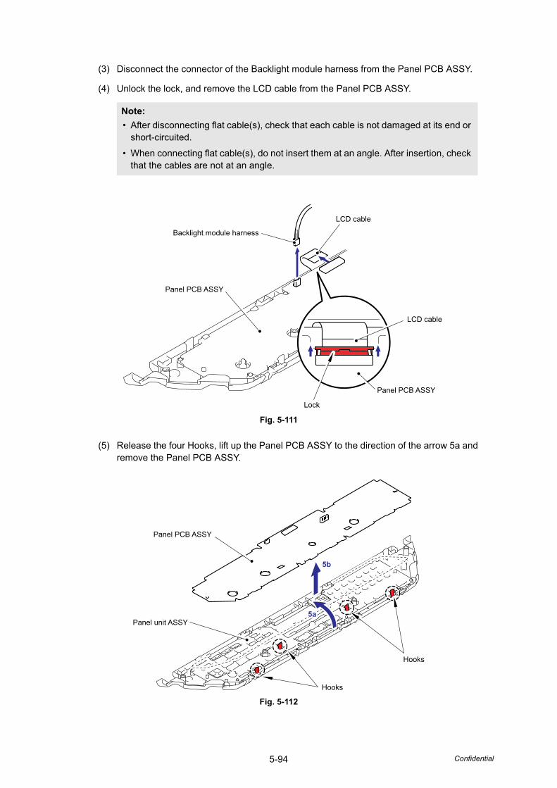
5-94 Confidential
(3) Disconnect the connector of the Backlight module harness from the Panel PCB ASSY.
(4) Unlock the lock, and remove the LCD cable from the Panel PCB ASSY.
Fig. 5-111
(5) Release the four Hooks, lift up the Panel PCB ASSY to the direction of the arrow 5a and remove the Panel PCB ASSY.
Fig. 5-112
Note: • After disconnecting flat cable(s), check that each cable is not damaged at its end or
short-circuited.
• When connecting flat cable(s), do not insert them at an angle. After insertion, check that the cables are not at an angle.
Backlight module harness
Panel PCB ASSY
Panel PCB ASSY
Lock
LCD cable
LCD cable
Panel PCB ASSY
Panel unit ASSY
Hooks
5b
Hooks
4a5a
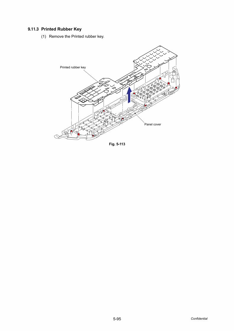
5-95 Confidential
9.11.3 Printed Rubber Key(1) Remove the Printed rubber key.
Fig. 5-113
Printed rubber key
Panel cover
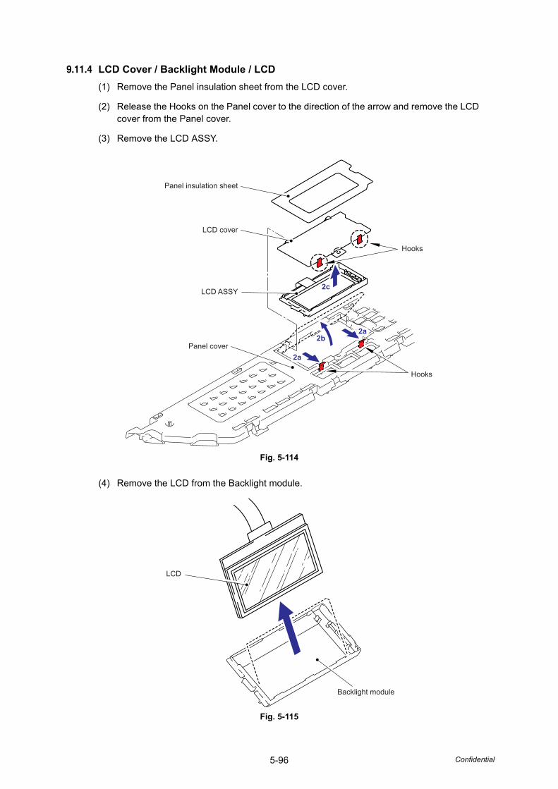
5-96 Confidential
9.11.4 LCD Cover / Backlight Module / LCD(1) Remove the Panel insulation sheet from the LCD cover.
(2) Release the Hooks on the Panel cover to the direction of the arrow and remove the LCD cover from the Panel cover.
(3) Remove the LCD ASSY.
Fig. 5-114
(4) Remove the LCD from the Backlight module.
Fig. 5-115
2a
2a2b
2c
2a
2a
Hooks
Hooks
Panel cover
LCD ASSY
LCD cover
Panel insulation sheet
LCD
Backlight module
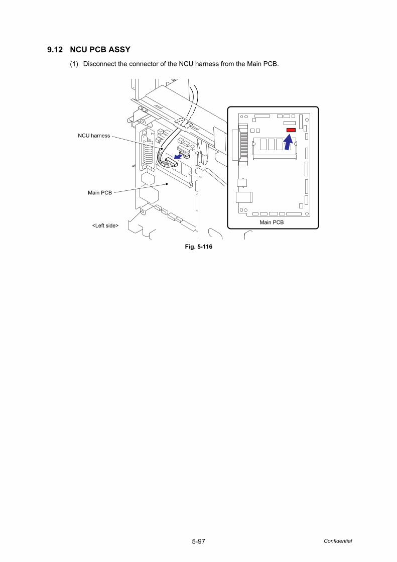
5-97 Confidential
9.12 NCU PCB ASSY(1) Disconnect the connector of the NCU harness from the Main PCB.
Fig. 5-116
NCU harness
Main PCB
Main PCB<Left side>
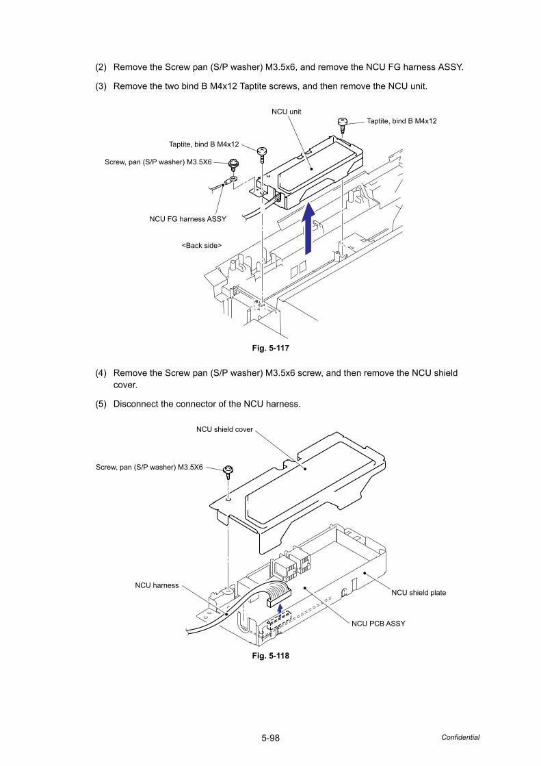
5-98 Confidential
(2) Remove the Screw pan (S/P washer) M3.5x6, and remove the NCU FG harness ASSY.
(3) Remove the two bind B M4x12 Taptite screws, and then remove the NCU unit.
Fig. 5-117
(4) Remove the Screw pan (S/P washer) M3.5x6 screw, and then remove the NCU shield cover.
(5) Disconnect the connector of the NCU harness.
Fig. 5-118
NCU unitTaptite, bind B M4x12
Taptite, bind B M4x12
Screw, pan (S/P washer) M3.5X6
NCU FG harness ASSY
<Back side>
NCU shield cover
Screw, pan (S/P washer) M3.5X6
NCU harness
NCU PCB ASSY
NCU shield plate
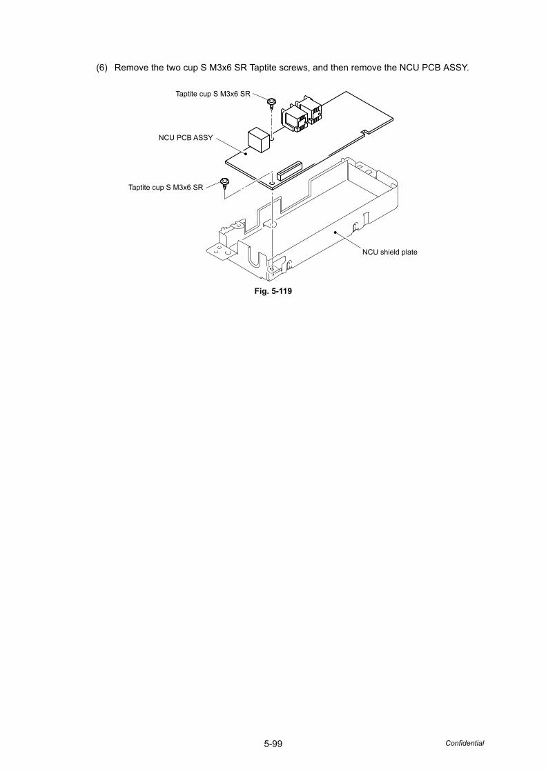
5-99 Confidential
(6) Remove the two cup S M3x6 SR Taptite screws, and then remove the NCU PCB ASSY.
Fig. 5-119
Taptite cup S M3x6 SR
Taptite cup S M3x6 SR
NCU PCB ASSY
NCU shield plate
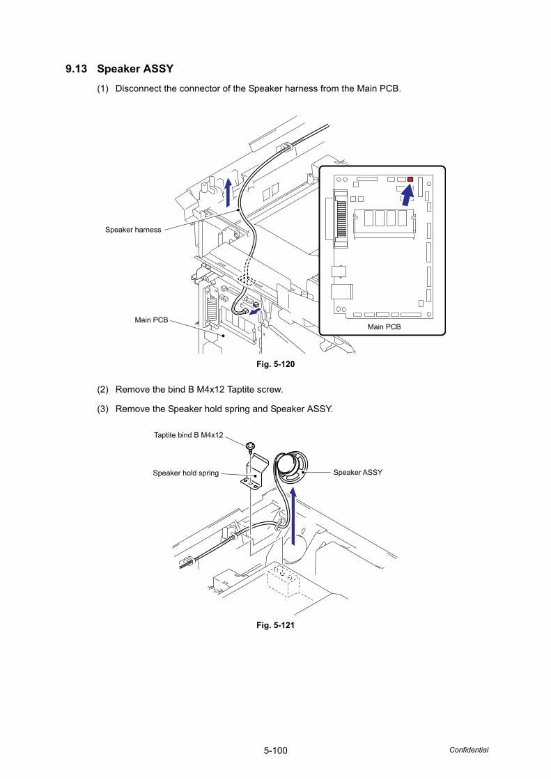
5-100 Confidential
9.13 Speaker ASSY(1) Disconnect the connector of the Speaker harness from the Main PCB.
Fig. 5-120
(2) Remove the bind B M4x12 Taptite screw.
(3) Remove the Speaker hold spring and Speaker ASSY.
Fig. 5-121
Speaker harness
Main PCBMain PCB
Speaker ASSYSpeaker hold spring
Taptite bind B M4x12
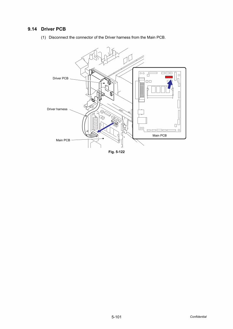
5-101 Confidential
9.14 Driver PCB(1) Disconnect the connector of the Driver harness from the Main PCB.
Fig. 5-122
Driver PCB
Driver harness
Main PCBMain PCB
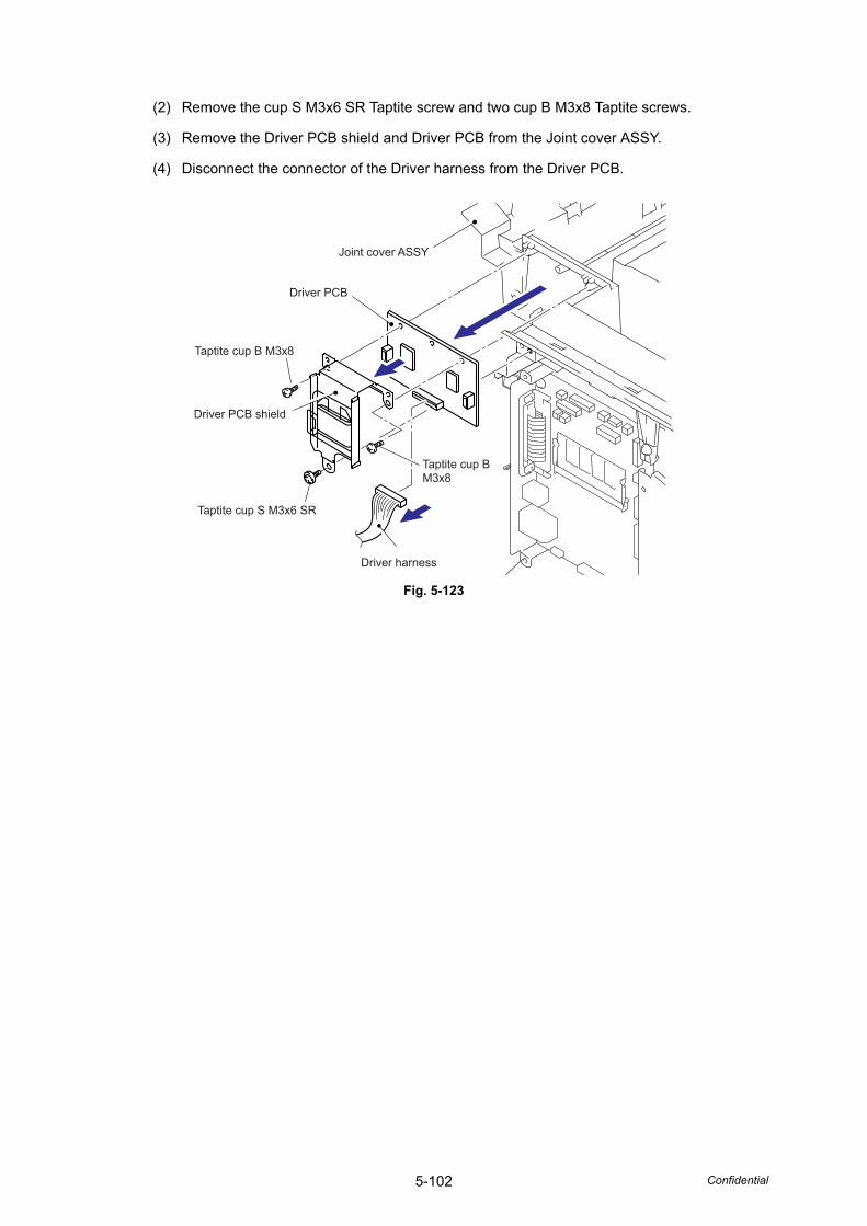
5-102 Confidential
(2) Remove the cup S M3x6 SR Taptite screw and two cup B M3x8 Taptite screws.
(3) Remove the Driver PCB shield and Driver PCB from the Joint cover ASSY.
(4) Disconnect the connector of the Driver harness from the Driver PCB.
Fig. 5-123
Joint cover ASSY
Driver PCB
Driver PCB shield
Taptite cup B M3x8
Taptite cup S M3x6 SR
Taptite cup BM3x8
Driver harness
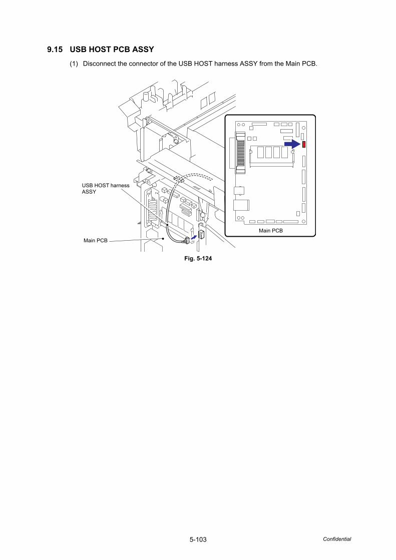
5-103 Confidential
9.15 USB HOST PCB ASSY(1) Disconnect the connector of the USB HOST harness ASSY from the Main PCB.
Fig. 5-124
Main PCB
USB HOST harnessASSY
Main PCB
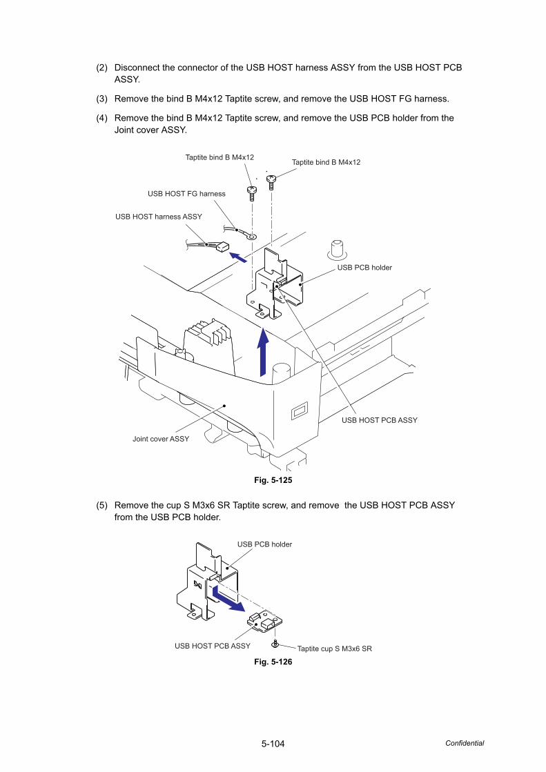
5-104 Confidential
(2) Disconnect the connector of the USB HOST harness ASSY from the USB HOST PCB ASSY.
(3) Remove the bind B M4x12 Taptite screw, and remove the USB HOST FG harness.
(4) Remove the bind B M4x12 Taptite screw, and remove the USB PCB holder from the Joint cover ASSY.
Fig. 5-125
(5) Remove the cup S M3x6 SR Taptite screw, and remove the USB HOST PCB ASSY from the USB PCB holder.
Fig. 5-126
Joint cover ASSY
USB HOST FG harness
USB HOST harness ASSY
USB PCB holder
USB HOST PCB ASSY
Taptite bind B M4x12Taptite bind B M4x12
USB HOST PCB ASSY
USB PCB holder
Taptite cup S M3x6 SR
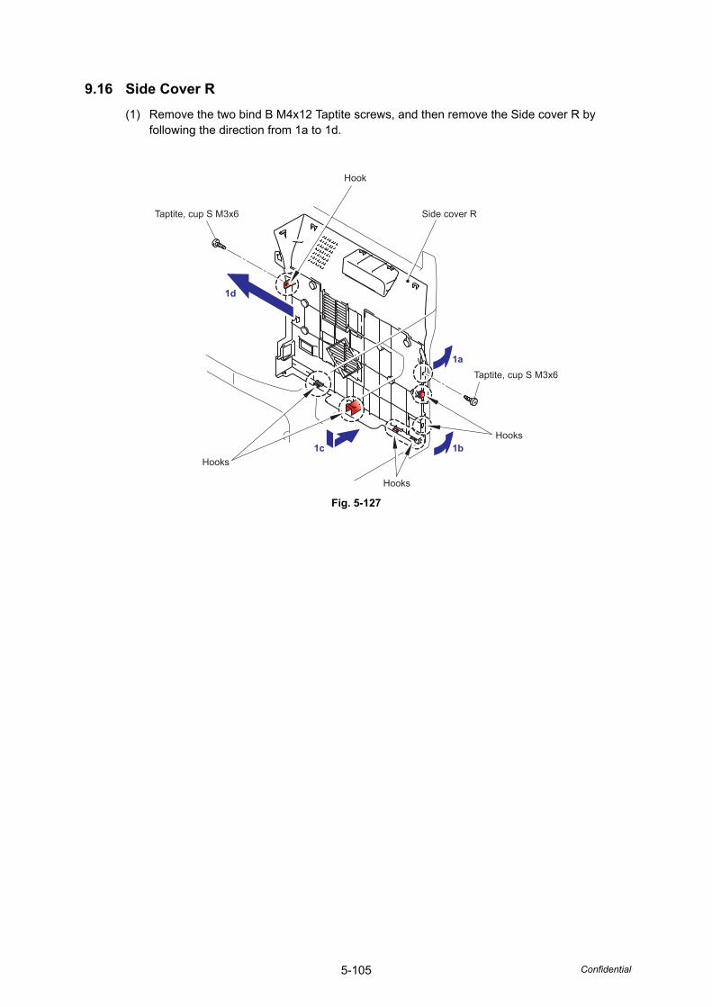
5-105 Confidential
9.16 Side Cover R(1) Remove the two bind B M4x12 Taptite screws, and then remove the Side cover R by
following the direction from 1a to 1d.
Fig. 5-127
1d
1c 1b
1a
Taptite, cup S M3x6
Taptite, cup S M3x6
Hook
Hooks
Hooks
Hooks
Side cover R

5-106 Confidential
9.17 Battery(1) Remove the Battery.
(2) Disconnect the connector of the Battery.
(3) Disconnect the connector of the Battery harness from the Main PCB, and then remove the Battery harness.
Fig. 5-128
DANGER• Never disassemble or recharge the battery.• Never dispose of the battery in fire.
WARNING• There is a danger of explosion if the battery is incorrectly replaced.• When replacing the battery, use the spare part authorized by Konica Minolta.• Batteries used should be disposed of in accordance with the local codes and
regulations.
GEFAHR• Die Batterie niemals zerlegen oder wieder aufladen.• Die Batterie niemals durch Verbrennen entsorgen.
WARNUNG• Wenn die Batterie inkorrekt ausgewechselt wird, besteht Explosionsgefahr.
Main PCB
Main PCB
Battery harness
2
1
3
Battery
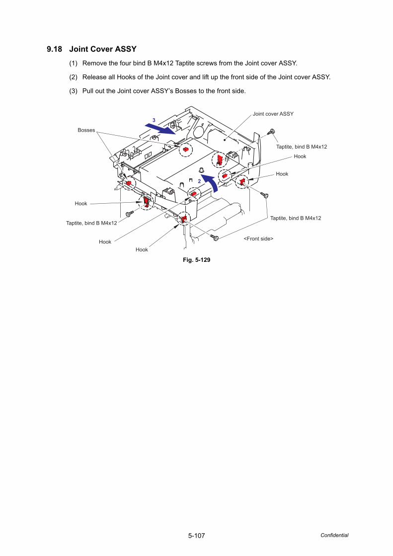
5-107 Confidential
9.18 Joint Cover ASSY(1) Remove the four bind B M4x12 Taptite screws from the Joint cover ASSY.
(2) Release all Hooks of the Joint cover and lift up the front side of the Joint cover ASSY.
(3) Pull out the Joint cover ASSY’s Bosses to the front side.
Fig. 5-129
3
<Front side>
2
Hook
Joint cover ASSY
Taptite, bind B M4x12
Taptite, bind B M4x12
Taptite, bind B M4x12
Hook
HookHook
Hook
Bosses
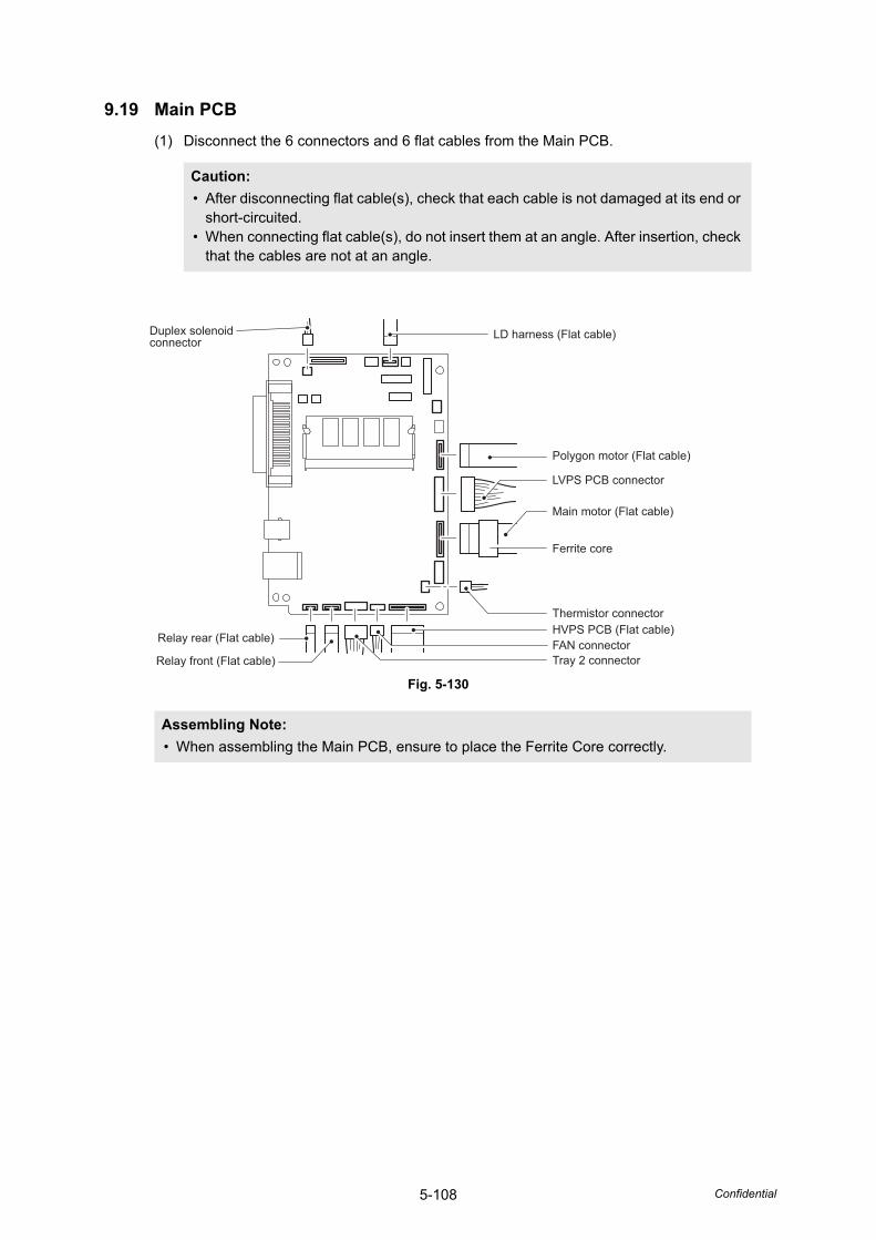
5-108 Confidential
9.19 Main PCB(1) Disconnect the 6 connectors and 6 flat cables from the Main PCB.
Fig. 5-130
Caution: • After disconnecting flat cable(s), check that each cable is not damaged at its end or
short-circuited.• When connecting flat cable(s), do not insert them at an angle. After insertion, check
that the cables are not at an angle.
Assembling Note: • When assembling the Main PCB, ensure to place the Ferrite Core correctly.
Duplex solenoid connector
Tray 2 connectorFAN connectorHVPS PCB (Flat cable)Thermistor connector
Main motor (Flat cable)
LVPS PCB connector
Polygon motor (Flat cable)
LD harness (Flat cable)
Ferrite core
Relay rear (Flat cable)
Relay front (Flat cable)
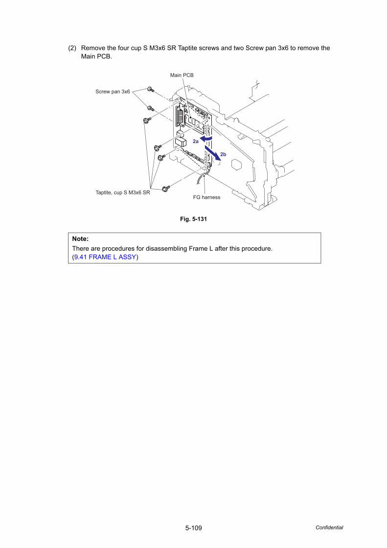
5-109 Confidential
(2) Remove the four cup S M3x6 SR Taptite screws and two Screw pan 3x6 to remove the Main PCB.
Fig. 5-131
Note:There are procedures for disassembling Frame L after this procedure.(9.41 FRAME L ASSY)
2a
2b
Main PCB
Taptite, cup S M3x6 SRFG harness
Screw pan 3x6
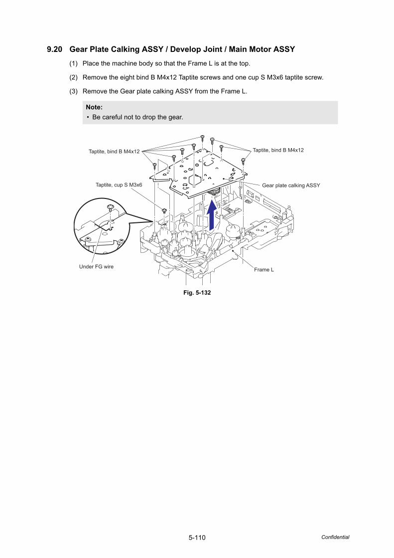
5-110 Confidential
9.20 Gear Plate Calking ASSY / Develop Joint / Main Motor ASSY(1) Place the machine body so that the Frame L is at the top.
(2) Remove the eight bind B M4x12 Taptite screws and one cup S M3x6 taptite screw.
(3) Remove the Gear plate calking ASSY from the Frame L.
Fig. 5-132
Note: • Be careful not to drop the gear.
Taptite, bind B M4x12 Taptite, bind B M4x12
Taptite, cup S M3x6
Under FG wire
Gear plate calking ASSY
Frame L
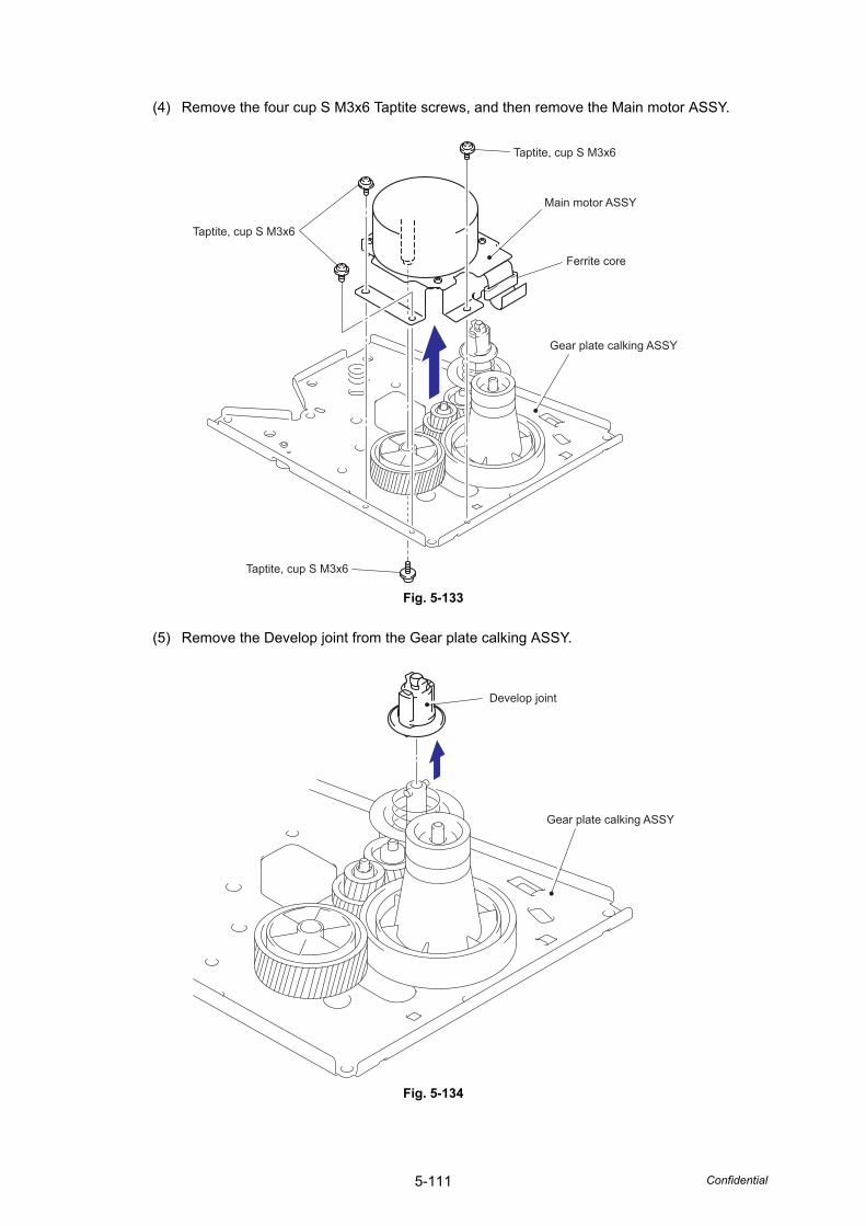
5-111 Confidential
(4) Remove the four cup S M3x6 Taptite screws, and then remove the Main motor ASSY.
Fig. 5-133
(5) Remove the Develop joint from the Gear plate calking ASSY.
Fig. 5-134
Taptite, cup S M3x6
Ferrite core
Main motor ASSY
Gear plate calking ASSY
Taptite, cup S M3x6
Taptite, cup S M3x6
Develop joint
Gear plate calking ASSY
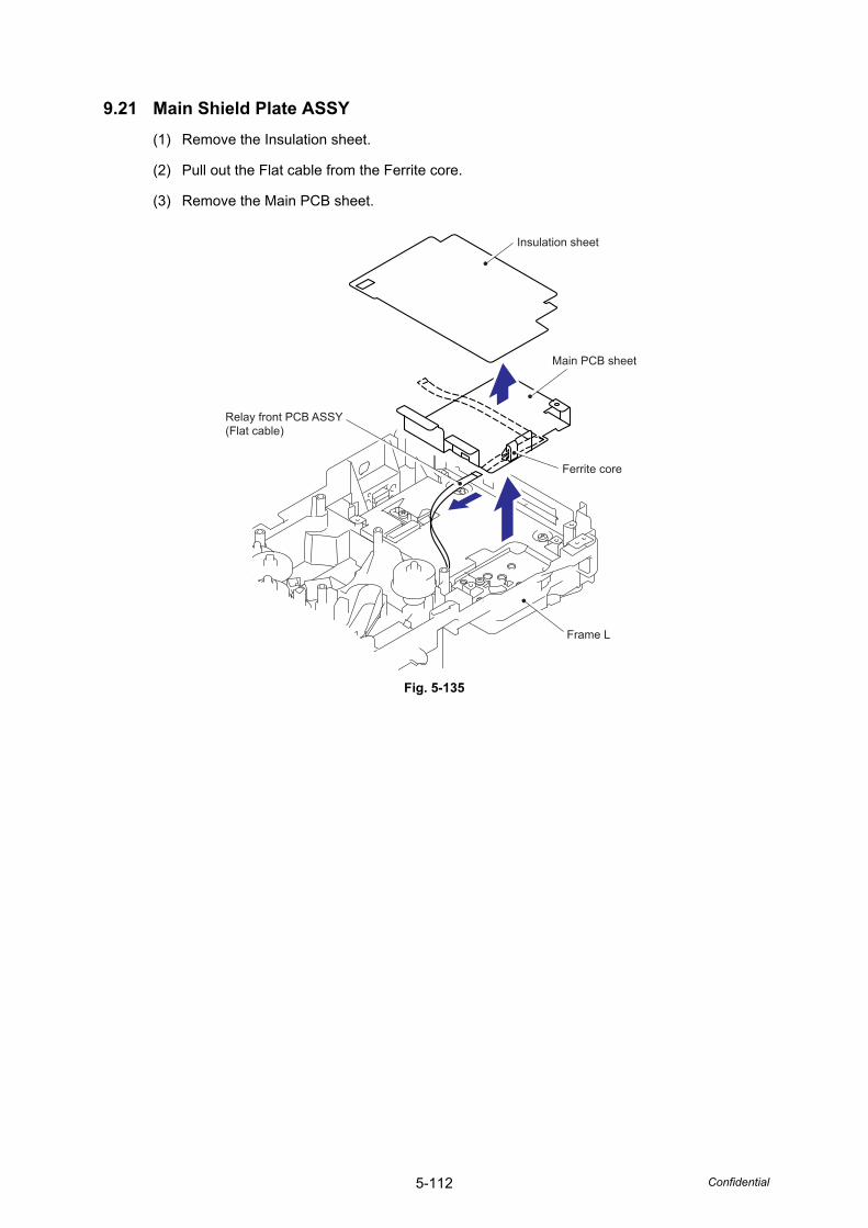
5-112 Confidential
9.21 Main Shield Plate ASSY(1) Remove the Insulation sheet.
(2) Pull out the Flat cable from the Ferrite core.
(3) Remove the Main PCB sheet.
Fig. 5-135
Insulation sheet
Relay front PCB ASSY(Flat cable)
Ferrite core
Frame L
Main PCB sheet
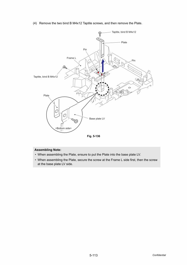
5-113 Confidential
(4) Remove the two bind B M4x12 Taptite screws, and then remove the Plate.
Fig. 5-136
Assembling Note: • When assembling the Plate, ensure to put the Plate into the base plate LV.
• When assembling the Plate, secure the screw at the Frame L side first, then the screw at the base plate LV side.
Taptite, bind B M4x12
Taptite, bind B M4x12
Frame L
Plate
Plate
Base plate LV
Pin
Pin
<Bottom side>
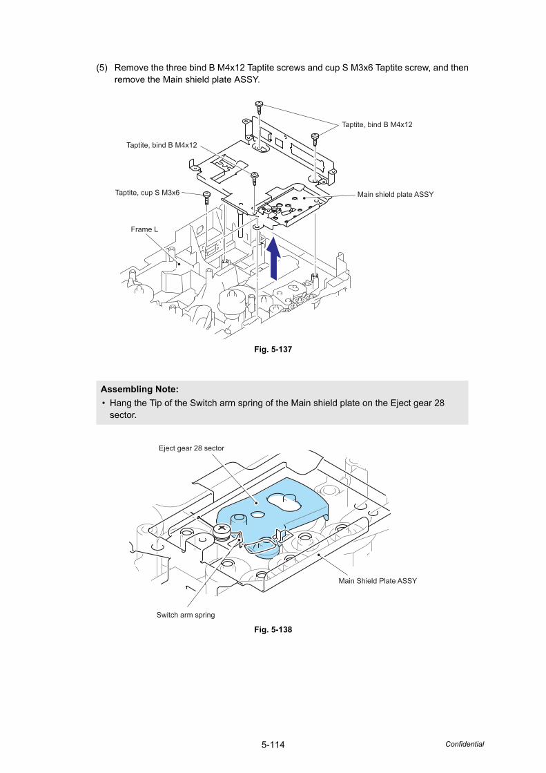
5-114 Confidential
(5) Remove the three bind B M4x12 Taptite screws and cup S M3x6 Taptite screw, and then remove the Main shield plate ASSY.
Fig. 5-137
Fig. 5-138
Assembling Note: • Hang the Tip of the Switch arm spring of the Main shield plate on the Eject gear 28
sector.
Taptite, bind B M4x12
Main shield plate ASSY
Taptite, bind B M4x12
Taptite, cup S M3x6
Frame L
Main Shield Plate ASSY
Eject gear 28 sector
Switch arm spring
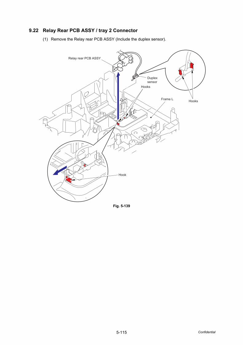
5-115 Confidential
9.22 Relay Rear PCB ASSY / tray 2 Connector(1) Remove the Relay rear PCB ASSY (Include the duplex sensor).
Fig. 5-139
Hooks
Hooks
Hook
Relay rear PCB ASSY
Frame L
Duplex sensor
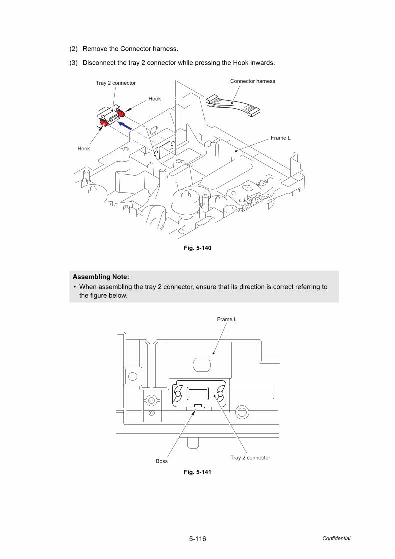
5-116 Confidential
(2) Remove the Connector harness.
(3) Disconnect the tray 2 connector while pressing the Hook inwards.
Fig. 5-140
Fig. 5-141
Assembling Note: • When assembling the tray 2 connector, ensure that its direction is correct referring to
the figure below.
Connector harness
Frame L
Hook
Tray 2 connector
Hook
Frame L
Tray 2 connectorBoss
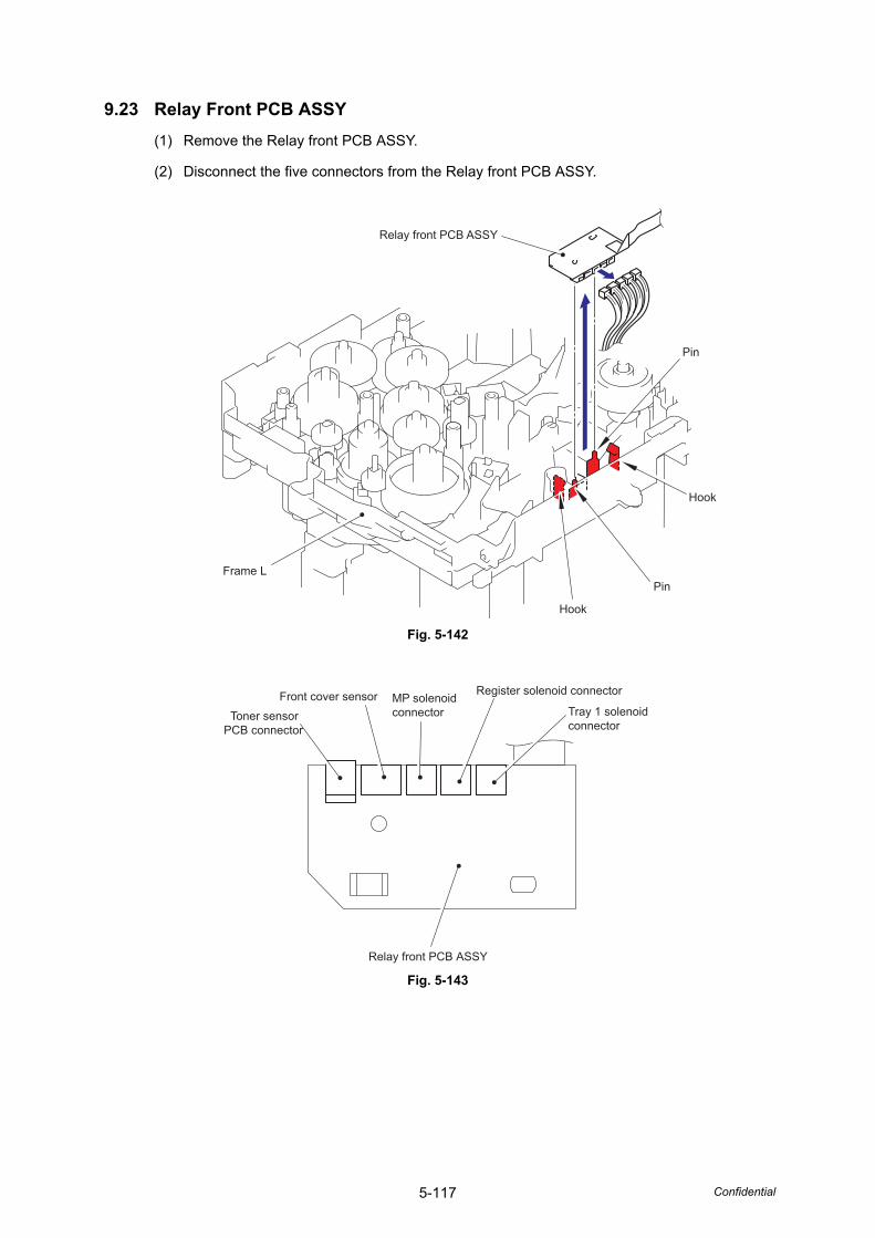
5-117 Confidential
9.23 Relay Front PCB ASSY(1) Remove the Relay front PCB ASSY.
(2) Disconnect the five connectors from the Relay front PCB ASSY.
Fig. 5-142
Fig. 5-143
Pin
Pin
Hook
Hook
Frame L
Relay front PCB ASSY
Tray 1 solenoid connector
Register solenoid connectorMP solenoid connector
Relay front PCB ASSY
Front cover sensorToner sensor
PCB connector
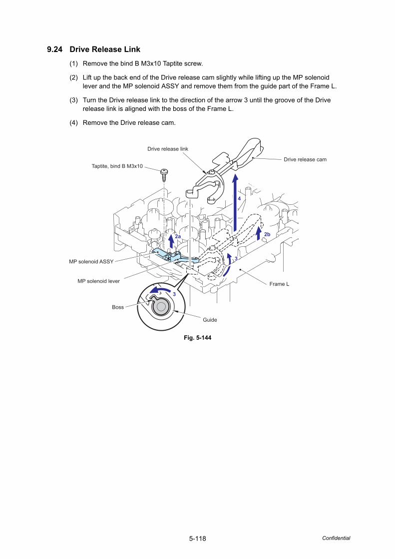
5-118 Confidential
9.24 Drive Release Link(1) Remove the bind B M3x10 Taptite screw.
(2) Lift up the back end of the Drive release cam slightly while lifting up the MP solenoid lever and the MP solenoid ASSY and remove them from the guide part of the Frame L.
(3) Turn the Drive release link to the direction of the arrow 3 until the groove of the Drive release link is aligned with the boss of the Frame L.
(4) Remove the Drive release cam.
Fig. 5-144
Drive release cam
Drive release link
Frame L
Guide
Boss
MP solenoid ASSY
Taptite, bind B M3x10
MP solenoid lever
2a 2b
4
3
3
2a 2b
4
3
3
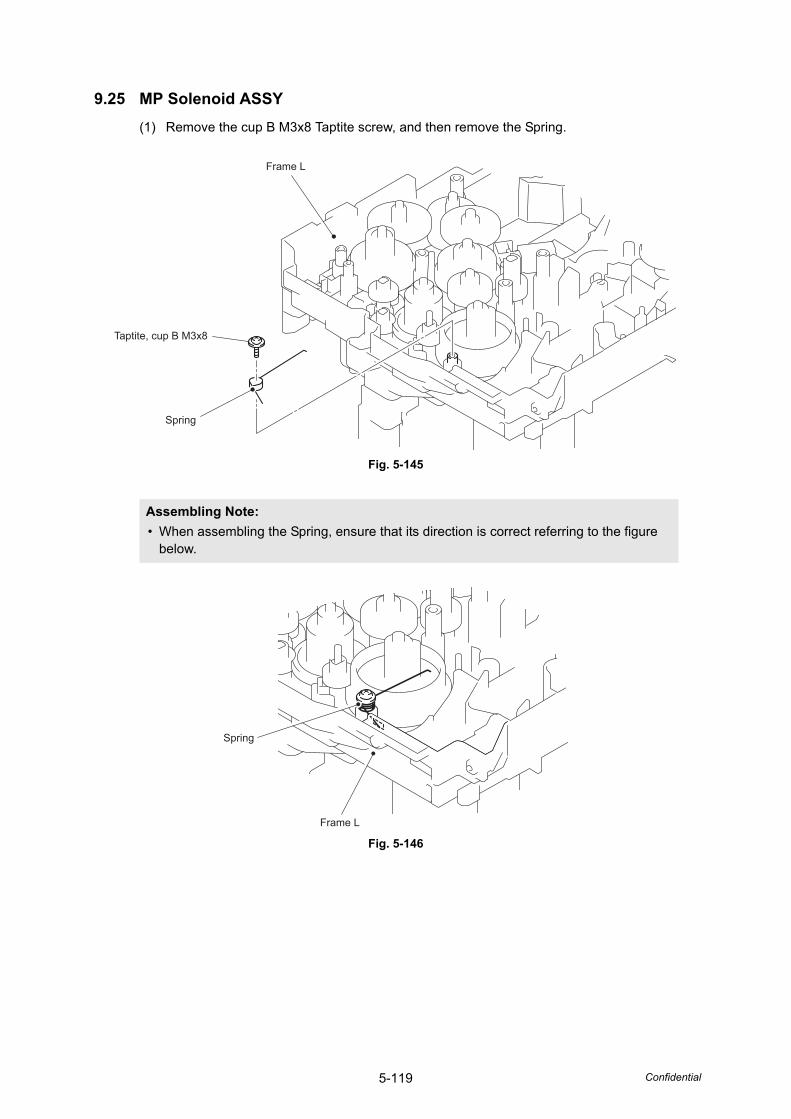
5-119 Confidential
9.25 MP Solenoid ASSY(1) Remove the cup B M3x8 Taptite screw, and then remove the Spring.
Fig. 5-145
Fig. 5-146
Assembling Note: • When assembling the Spring, ensure that its direction is correct referring to the figure
below.
Frame L
Taptite, cup B M3x8
Spring
Frame L
Spring
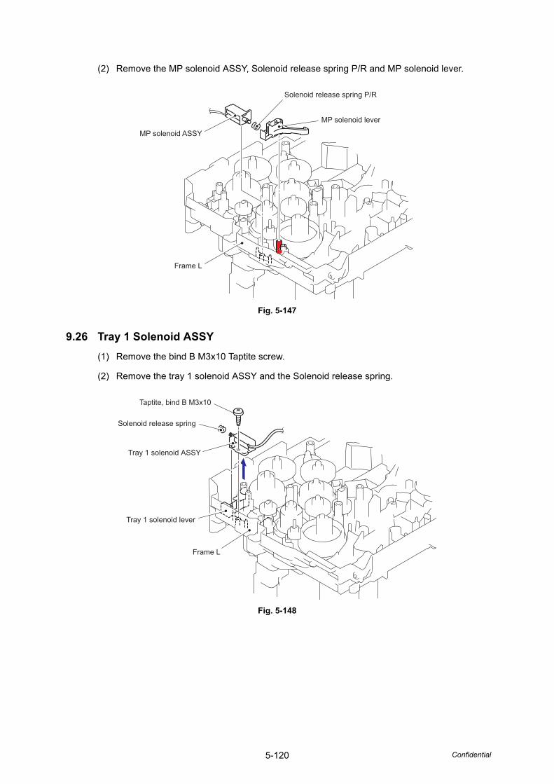
5-120 Confidential
(2) Remove the MP solenoid ASSY, Solenoid release spring P/R and MP solenoid lever.
Fig. 5-147
9.26 Tray 1 Solenoid ASSY(1) Remove the bind B M3x10 Taptite screw.
(2) Remove the tray 1 solenoid ASSY and the Solenoid release spring.
Fig. 5-148
MP solenoid ASSY
Solenoid release spring P/R
MP solenoid lever
Frame L
Taptite, bind B M3x10
Solenoid release spring
Tray 1 solenoid ASSY
Tray 1 solenoid lever
Frame L
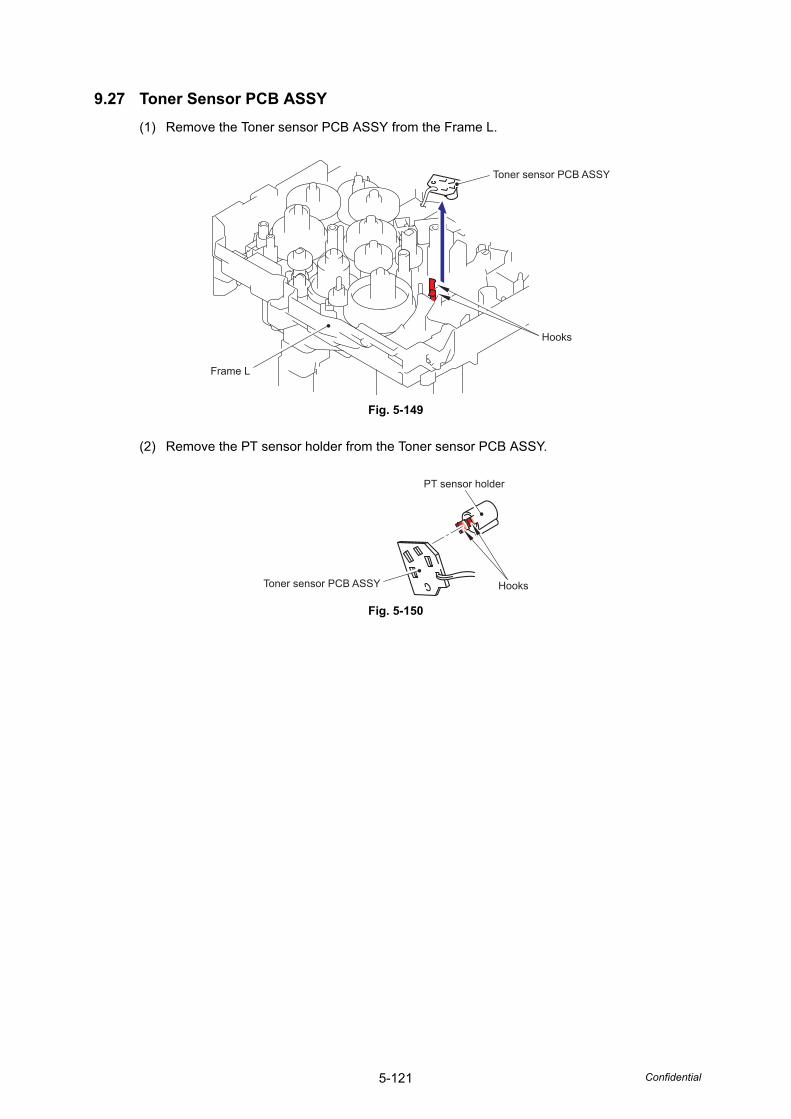
5-121 Confidential
9.27 Toner Sensor PCB ASSY(1) Remove the Toner sensor PCB ASSY from the Frame L.
Fig. 5-149
(2) Remove the PT sensor holder from the Toner sensor PCB ASSY.
Fig. 5-150
Frame L
Toner sensor PCB ASSY
Hooks
PT sensor holder
HooksToner sensor PCB ASSY
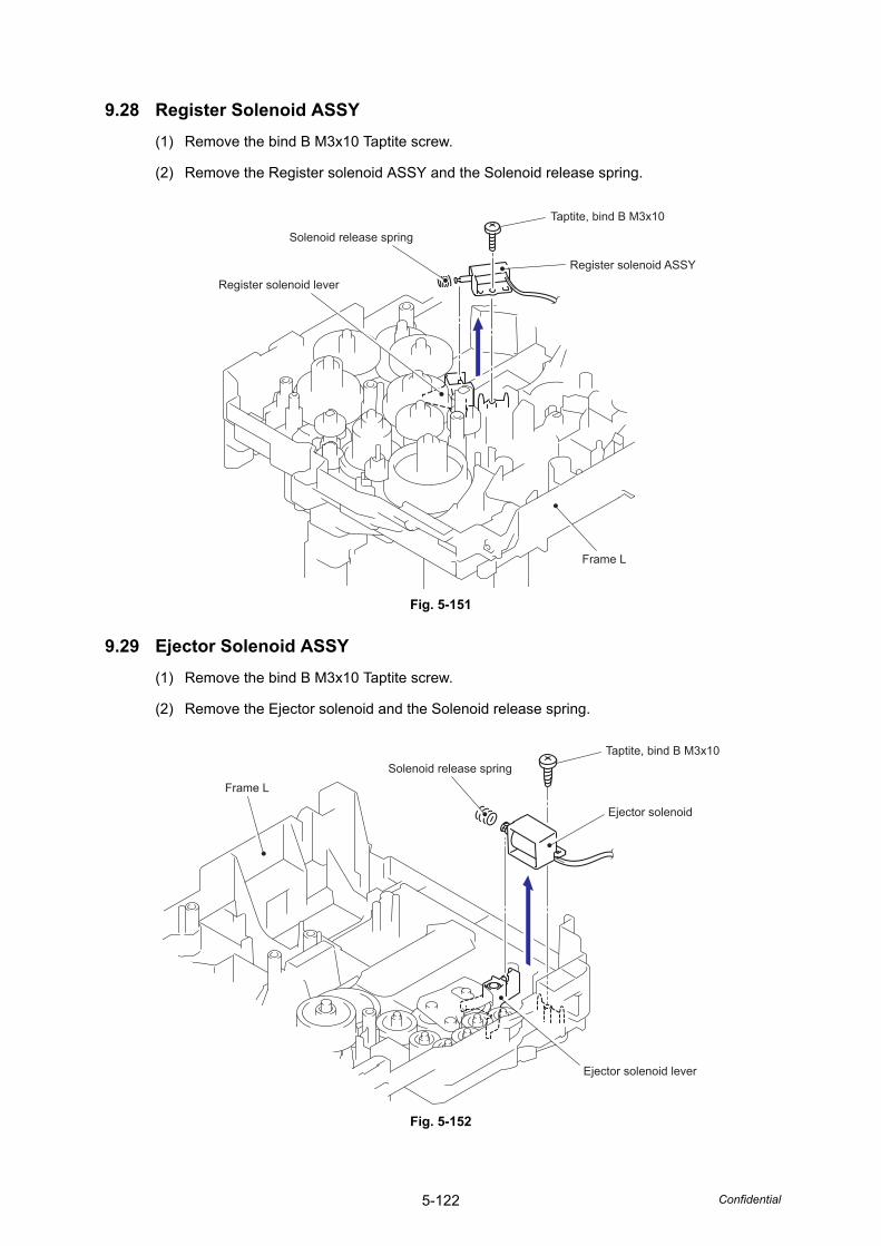
5-122 Confidential
9.28 Register Solenoid ASSY(1) Remove the bind B M3x10 Taptite screw.
(2) Remove the Register solenoid ASSY and the Solenoid release spring.
Fig. 5-151
9.29 Ejector Solenoid ASSY(1) Remove the bind B M3x10 Taptite screw.
(2) Remove the Ejector solenoid and the Solenoid release spring.
Fig. 5-152
Solenoid release spring
Taptite, bind B M3x10
Register solenoid ASSY
Frame L
Register solenoid lever
Taptite, bind B M3x10
Ejector solenoid
Ejector solenoid lever
Solenoid release springFrame L
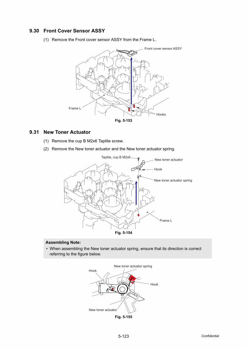
5-123 Confidential
9.30 Front Cover Sensor ASSY(1) Remove the Front cover sensor ASSY from the Frame L.
Fig. 5-153
9.31 New Toner Actuator(1) Remove the cup B M2x6 Taptite screw.
(2) Remove the New toner actuator and the New toner actuator spring.
Fig. 5-154
Fig. 5-155
Assembling Note: • When assembling the New toner actuator spring, ensure that its direction is correct
referring to the figure below.
Frame L
Front cover sensor ASSY
Hooks
Frame L
New toner actuator spring
New toner actuatorTaptite, cup B M2x6
Hook
New toner actuator spring
New toner actuator
Hook
Hook
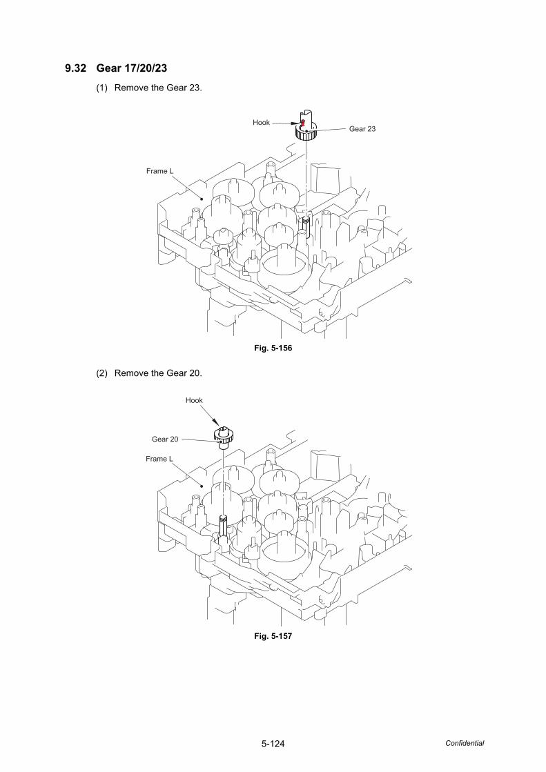
5-124 Confidential
9.32 Gear 17/20/23(1) Remove the Gear 23.
Fig. 5-156
(2) Remove the Gear 20.
Fig. 5-157
Frame L
HookGear 23
Frame L
Gear 20
Hook
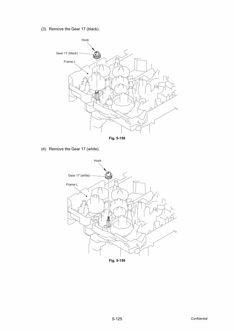
5-125 Confidential
(3) Remove the Gear 17 (black).
Fig. 5-158
(4) Remove the Gear 17 (white).
Fig. 5-159
Frame L
Gear 17 (black)
Hook
Frame L
Gear 17 (white)
Hook
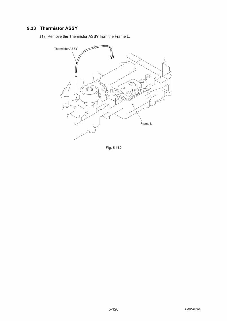
5-126 Confidential
9.33 Thermistor ASSY(1) Remove the Thermistor ASSY from the Frame L.
Fig. 5-160
Frame L
Thermistor ASSY
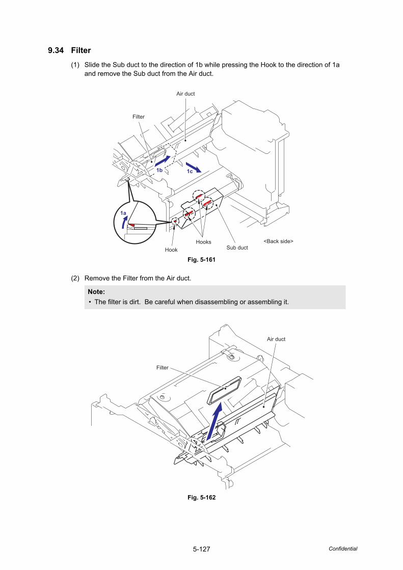
5-127 Confidential
9.34 Filter(1) Slide the Sub duct to the direction of 1b while pressing the Hook to the direction of 1a
and remove the Sub duct from the Air duct.
Fig. 5-161
(2) Remove the Filter from the Air duct.
Fig. 5-162
Note: • The filter is dirt. Be careful when disassembling or assembling it.
1a
1b 1c
Air duct
Filter
HookHooks
Sub duct<Back side>
Air duct
Filter
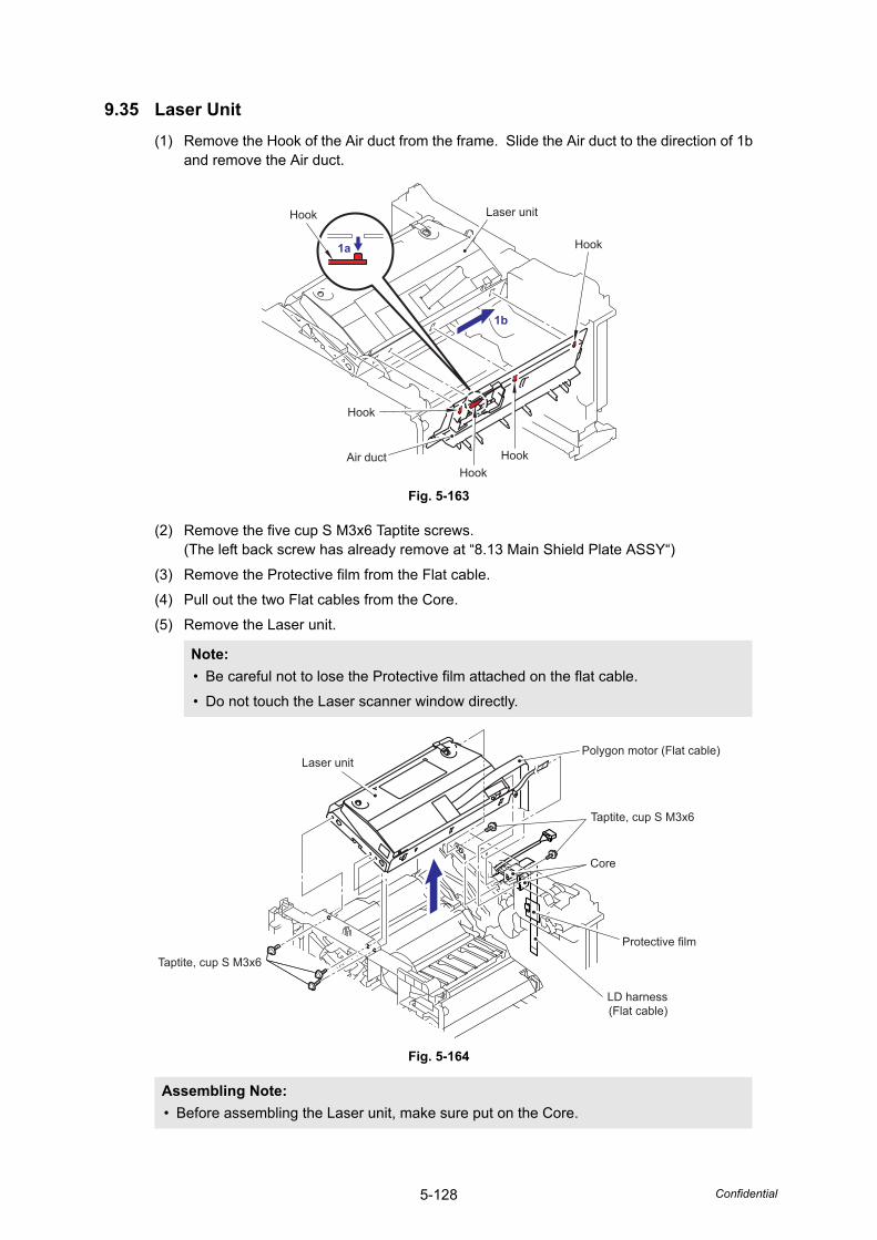
5-128 Confidential
9.35 Laser Unit(1) Remove the Hook of the Air duct from the frame. Slide the Air duct to the direction of 1b
and remove the Air duct.
Fig. 5-163
(2) Remove the five cup S M3x6 Taptite screws.(The left back screw has already remove at “8.13 Main Shield Plate ASSY“)
(3) Remove the Protective film from the Flat cable.
(4) Pull out the two Flat cables from the Core.
(5) Remove the Laser unit.
Fig. 5-164
Note: • Be careful not to lose the Protective film attached on the flat cable.
• Do not touch the Laser scanner window directly.
Assembling Note: • Before assembling the Laser unit, make sure put on the Core.
Hook
Hook
HookHook
Hook
Laser unit
Air duct
1b
1a
Taptite, cup S M3x6
Core
Protective film
Laser unit
Taptite, cup S M3x6
Polygon motor (Flat cable)
LD harness(Flat cable)
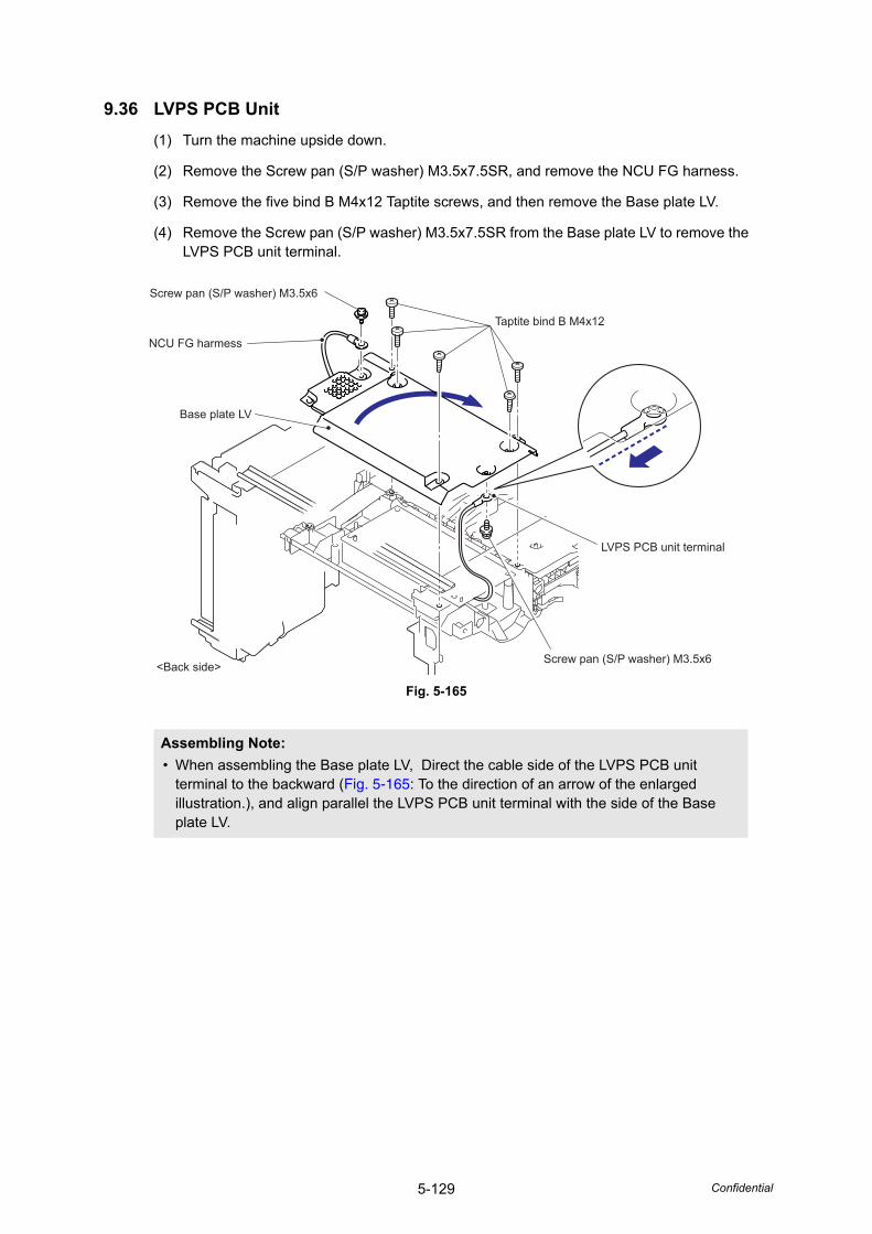
5-129 Confidential
9.36 LVPS PCB Unit(1) Turn the machine upside down.
(2) Remove the Screw pan (S/P washer) M3.5x7.5SR, and remove the NCU FG harness.
(3) Remove the five bind B M4x12 Taptite screws, and then remove the Base plate LV.
(4) Remove the Screw pan (S/P washer) M3.5x7.5SR from the Base plate LV to remove the LVPS PCB unit terminal.
Fig. 5-165
Assembling Note: • When assembling the Base plate LV, Direct the cable side of the LVPS PCB unit
terminal to the backward (Fig. 5-165: To the direction of an arrow of the enlarged illustration.), and align parallel the LVPS PCB unit terminal with the side of the Base plate LV.
LVPS PCB unit terminal
Screw pan (S/P washer) M3.5x6
Screw pan (S/P washer) M3.5x6
Taptite bind B M4x12
Base plate LV
<Back side>
NCU FG harmess
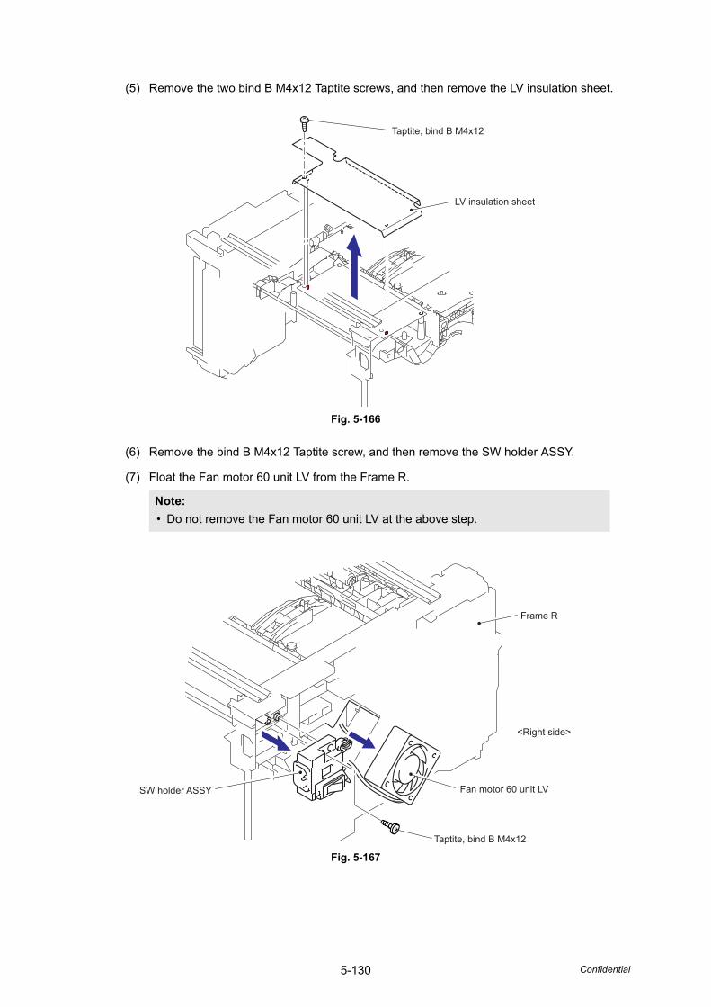
5-130 Confidential
(5) Remove the two bind B M4x12 Taptite screws, and then remove the LV insulation sheet.
Fig. 5-166
(6) Remove the bind B M4x12 Taptite screw, and then remove the SW holder ASSY.
(7) Float the Fan motor 60 unit LV from the Frame R.
Fig. 5-167
Note: • Do not remove the Fan motor 60 unit LV at the above step.
LV insulation sheet
Taptite, bind B M4x12
Frame R
Fan motor 60 unit LV
<Right side>
Taptite, bind B M4x12
SW holder ASSY
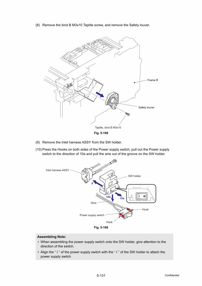
5-131 Confidential
(8) Remove the bind B M3x10 Taptite screw, and remove the Safety louver.
Fig. 5-168
(9) Remove the Inlet harness ASSY from the SW holder.
(10) Press the Hooks on both sides of the Power supply switch, pull out the Power supply switch to the direction of 10a and pull the wire out of the groove on the SW holder.
Fig. 5-169
Assembling Note: • When assembling the power supply switch onto the SW holder, give attention to the
direction of the switch.
• Align the “ I ” of the power supply switch with the “ I ” of the SW holder to attach the power supply switch
Safety louver
Frame R
Taptite, bind B M3x10
Inlet harness ASSY
Power supply switch
Wire
Hook
Hook
SW holder
9
10b 10a
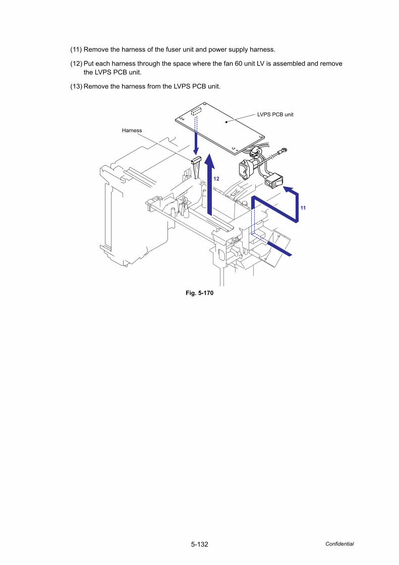
5-132 Confidential
(11) Remove the harness of the fuser unit and power supply harness.
(12) Put each harness through the space where the fan 60 unit LV is assembled and remove the LVPS PCB unit.
(13) Remove the harness from the LVPS PCB unit.
Fig. 5-170
11
12
LVPS PCB unit
Harness
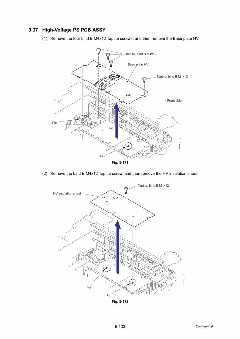
5-133 Confidential
9.37 High-Voltage PS PCB ASSY(1) Remove the four bind B M4x12 Taptite screws, and then remove the Base plate HV.
Fig. 5-171
(2) Remove the bind B M4x12 Taptite screw, and then remove the HV insulation sheet.
Fig. 5-172
Taptite, bind B M4x12
Taptite, bind B M4x12
<Front side>
Base plate HV
Pin
Pin
Taptite, bind B M4x12
HV insulation sheet
Pin
Pin
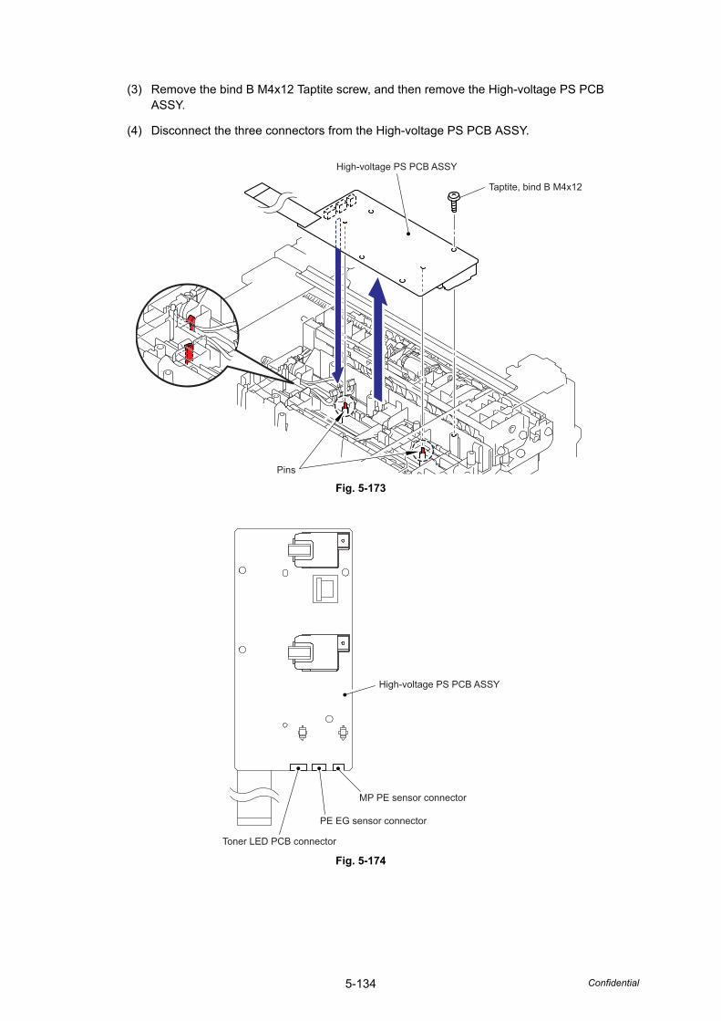
5-134 Confidential
(3) Remove the bind B M4x12 Taptite screw, and then remove the High-voltage PS PCB ASSY.
(4) Disconnect the three connectors from the High-voltage PS PCB ASSY.
Fig. 5-173
Fig. 5-174
High-voltage PS PCB ASSY
Taptite, bind B M4x12
Pins
High-voltage PS PCB ASSY
PE EG sensor connector
MP PE sensor connector
Toner LED PCB connector
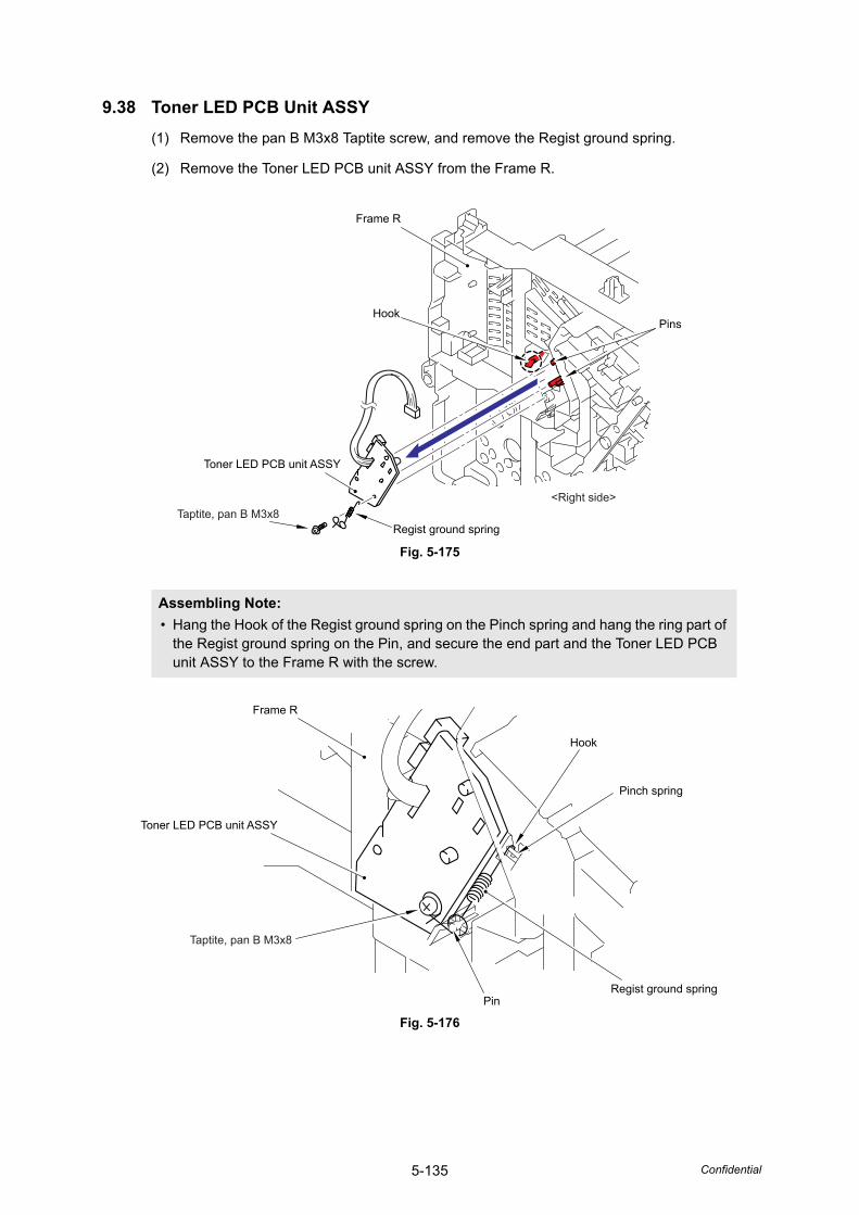
5-135 Confidential
9.38 Toner LED PCB Unit ASSY(1) Remove the pan B M3x8 Taptite screw, and remove the Regist ground spring.
(2) Remove the Toner LED PCB unit ASSY from the Frame R.
Fig. 5-175
Fig. 5-176
Assembling Note: • Hang the Hook of the Regist ground spring on the Pinch spring and hang the ring part of
the Regist ground spring on the Pin, and secure the end part and the Toner LED PCB unit ASSY to the Frame R with the screw.
Regist ground springTaptite, pan B M3x8
Toner LED PCB unit ASSY
HookPins
Frame R
<Right side>
Taptite, pan B M3x8
Toner LED PCB unit ASSY
Pinch spring
Hook
PinRegist ground spring
Frame R
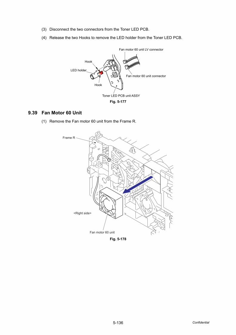
5-136 Confidential
(3) Disconnect the two connectors from the Toner LED PCB.
(4) Release the two Hooks to remove the LED holder from the Toner LED PCB.
Fig. 5-177
9.39 Fan Motor 60 Unit(1) Remove the Fan motor 60 unit from the Frame R.
Fig. 5-178
Hook
Hook
Toner LED PCB unit ASSY
LED holder
Fan motor 60 unit LV connector
Fan motor 60 unit connector
<Right side>
Fan motor 60 unit
Frame R
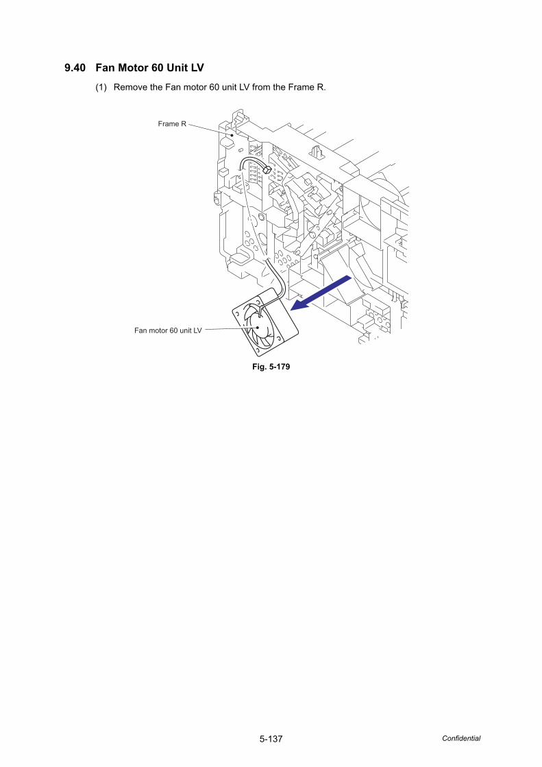
5-137 Confidential
9.40 Fan Motor 60 Unit LV(1) Remove the Fan motor 60 unit LV from the Frame R.
Fig. 5-179
Frame R
Fan motor 60 unit LV
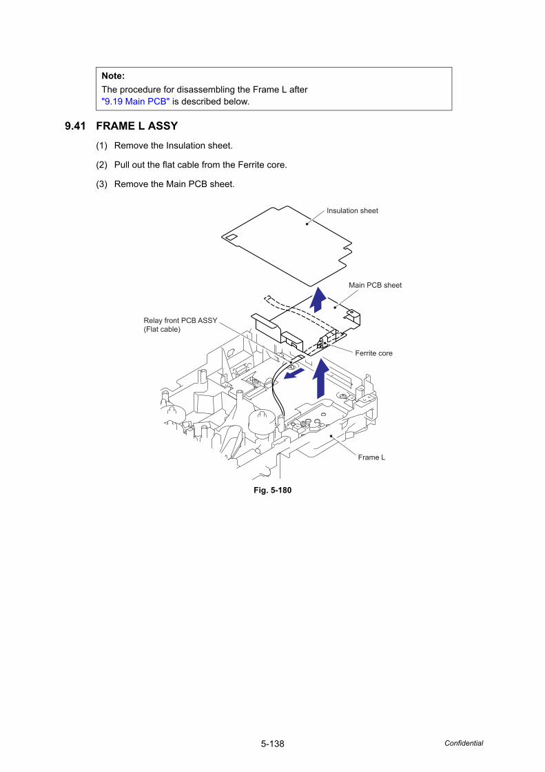
5-138 Confidential
9.41 FRAME L ASSY(1) Remove the Insulation sheet.
(2) Pull out the flat cable from the Ferrite core.
(3) Remove the Main PCB sheet.
Fig. 5-180
Note:The procedure for disassembling the Frame L after "9.19 Main PCB" is described below.
Insulation sheet
Relay front PCB ASSY(Flat cable)
Ferrite core
Frame L
Main PCB sheet
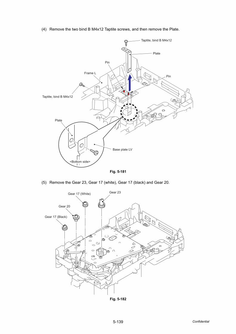
5-139 Confidential
(4) Remove the two bind B M4x12 Taptite screws, and then remove the Plate.
Fig. 5-181
(5) Remove the Gear 23, Gear 17 (white), Gear 17 (black) and Gear 20.
Fig. 5-182
Taptite, bind B M4x12
Taptite, bind B M4x12
Frame L
Plate
Plate
Base plate LV
Pin
Pin
<Bottom side>
Gear 17 (Black)
Gear 20
Gear 17 (White) Gear 23
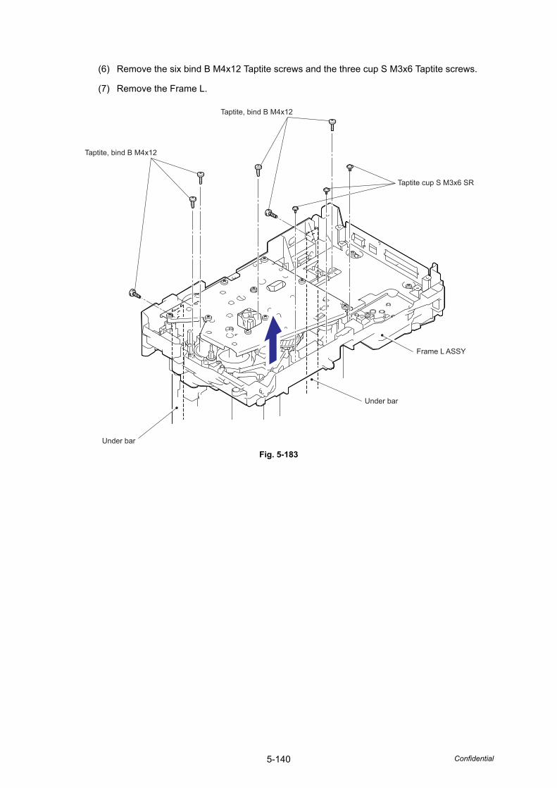
5-140 Confidential
(6) Remove the six bind B M4x12 Taptite screws and the three cup S M3x6 Taptite screws.
(7) Remove the Frame L.
Fig. 5-183
Taptite, bind B M4x12
Taptite, bind B M4x12
Taptite cup S M3x6 SR
Under bar
Under bar
Frame L ASSY
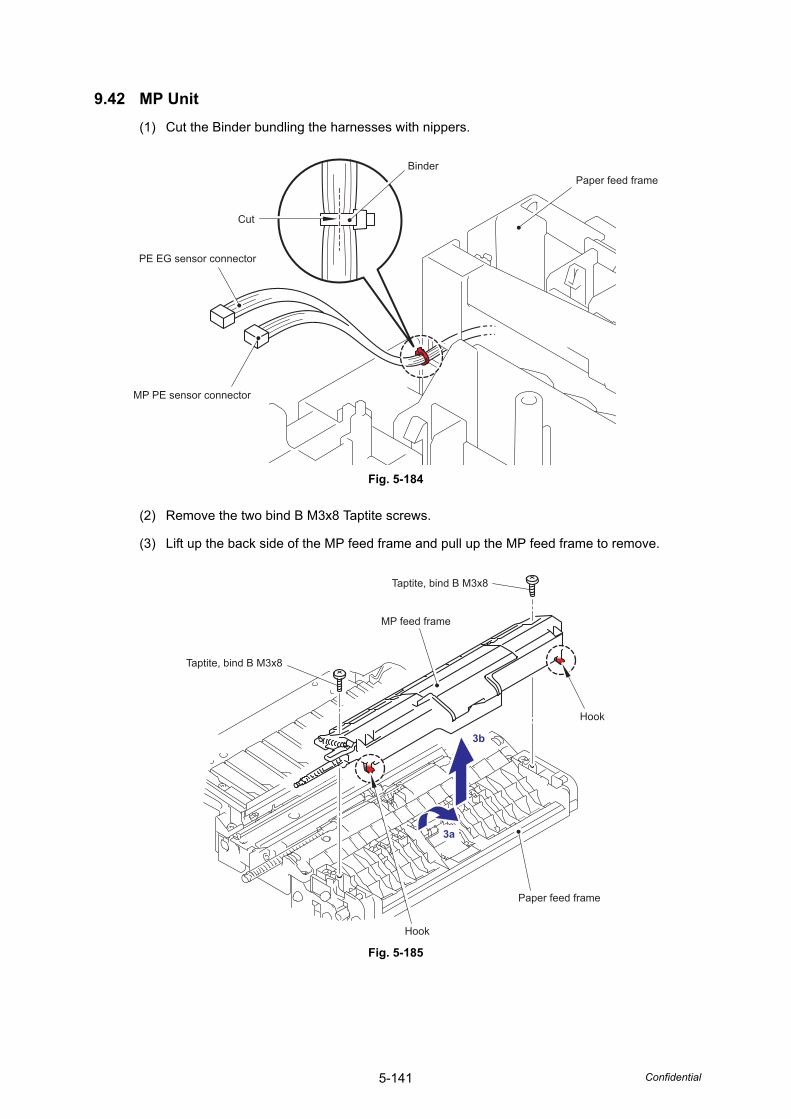
5-141 Confidential
9.42 MP Unit(1) Cut the Binder bundling the harnesses with nippers.
Fig. 5-184
(2) Remove the two bind B M3x8 Taptite screws.
(3) Lift up the back side of the MP feed frame and pull up the MP feed frame to remove.
Fig. 5-185
BinderPaper feed frame
Cut
MP PE sensor connector
PE EG sensor connector
Hook
Hook
Paper feed frame
Taptite, bind B M3x8
MP feed frame
3b
3a
Taptite, bind B M3x8
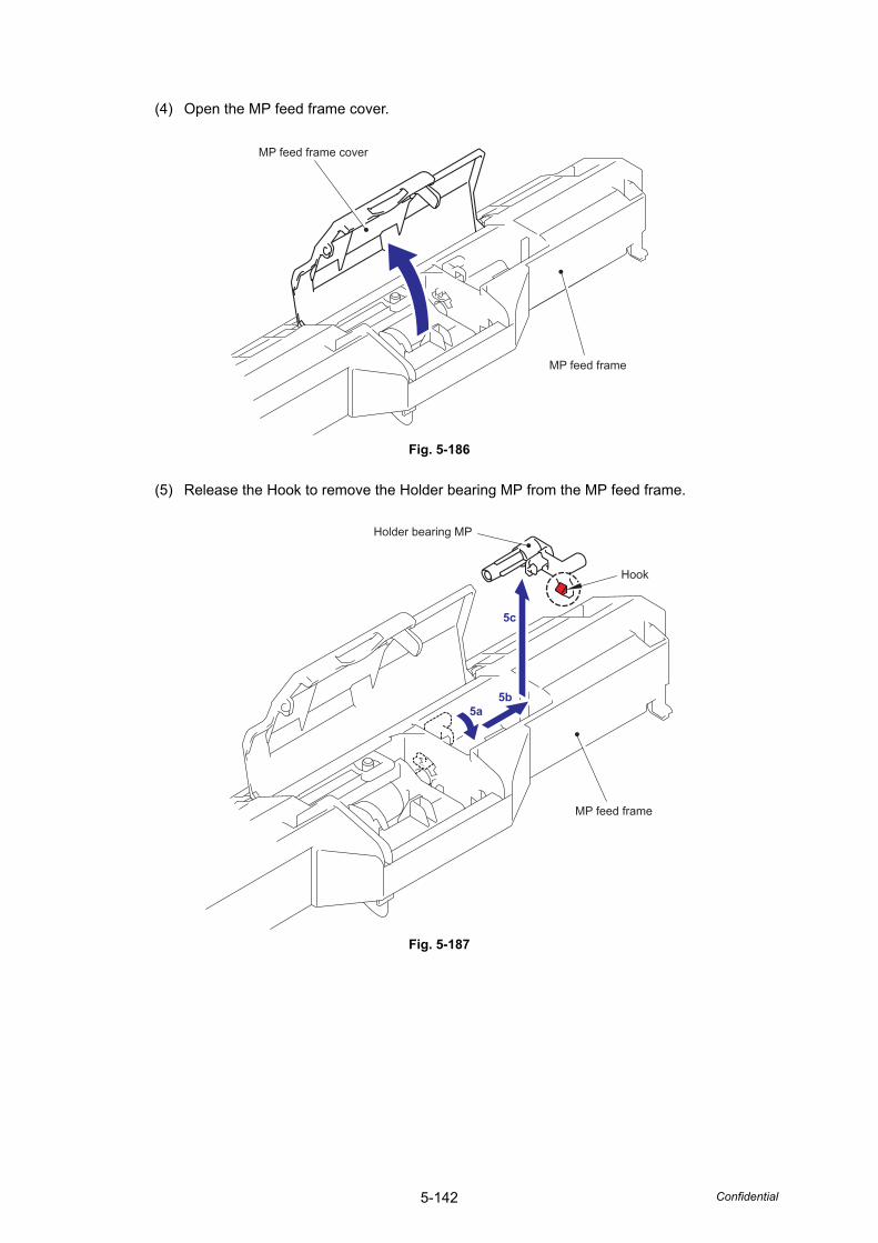
5-142 Confidential
(4) Open the MP feed frame cover.
Fig. 5-186
(5) Release the Hook to remove the Holder bearing MP from the MP feed frame.
Fig. 5-187
MP feed frame cover
MP feed frame
Hook
Holder bearing MP
MP feed frame
5c
5b5a
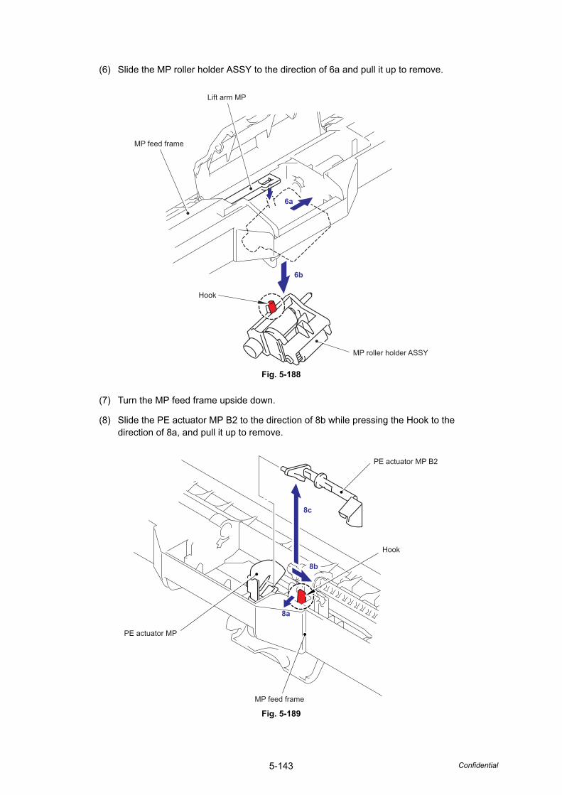
5-143 Confidential
(6) Slide the MP roller holder ASSY to the direction of 6a and pull it up to remove.
Fig. 5-188
(7) Turn the MP feed frame upside down.
(8) Slide the PE actuator MP B2 to the direction of 8b while pressing the Hook to the direction of 8a, and pull it up to remove.
Fig. 5-189
Hook
Lift arm MP
MP roller holder ASSY
MP feed frame
6a
6b
PE actuator MP B2
Hook
MP feed frame
PE actuator MP
8b
8c
8a
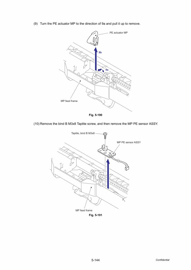
5-144 Confidential
(9) Turn the PE actuator MP to the direction of 9a and pull it up to remove.
Fig. 5-190
(10) Remove the bind B M3x8 Taptite screw, and then remove the MP PE sensor ASSY.
Fig. 5-191
MP feed frame
PE actuator MP
9b
9a
MP PE sensor ASSY
Taptite, bind B M3x8
MP feed frame
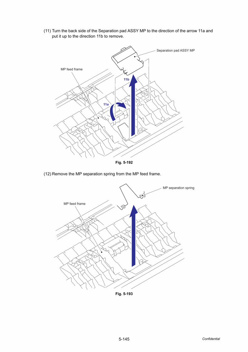
5-145 Confidential
(11) Turn the back side of the Separation pad ASSY MP to the direction of the arrow 11a and put it up to the direction 11b to remove.
Fig. 5-192
(12) Remove the MP separation spring from the MP feed frame.
Fig. 5-193
MP feed frame
Separation pad ASSY MP
11b
11a
MP feed frame
MP separation spring
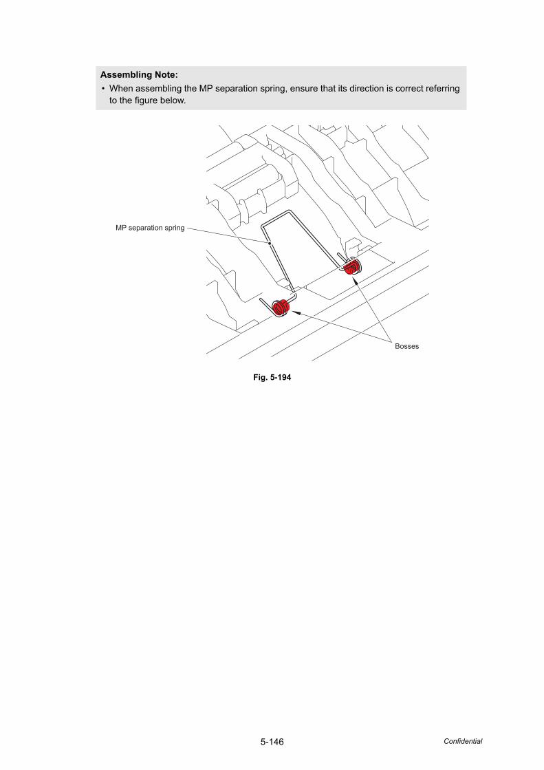
5-146 Confidential
Fig. 5-194
Assembling Note: • When assembling the MP separation spring, ensure that its direction is correct referring
to the figure below.
Bosses
MP separation spring
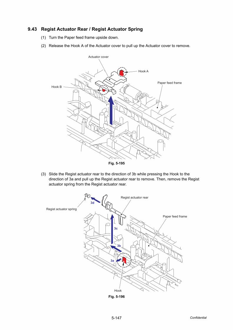
5-147 Confidential
9.43 Regist Actuator Rear / Regist Actuator Spring(1) Turn the Paper feed frame upside down.
(2) Release the Hook A of the Actuator cover to pull up the Actuator cover to remove.
Fig. 5-195
(3) Slide the Regist actuator rear to the direction of 3b while pressing the Hook to the direction of 3a and pull up the Regist actuator rear to remove. Then, remove the Regist actuator spring from the Regist actuator rear.
Fig. 5-196
Hook A
Paper feed frame
Actuator cover
Hook B
Hook
Regist actuator rear
Paper feed frame
3b
3a
3c
3d
Regist actuator spring
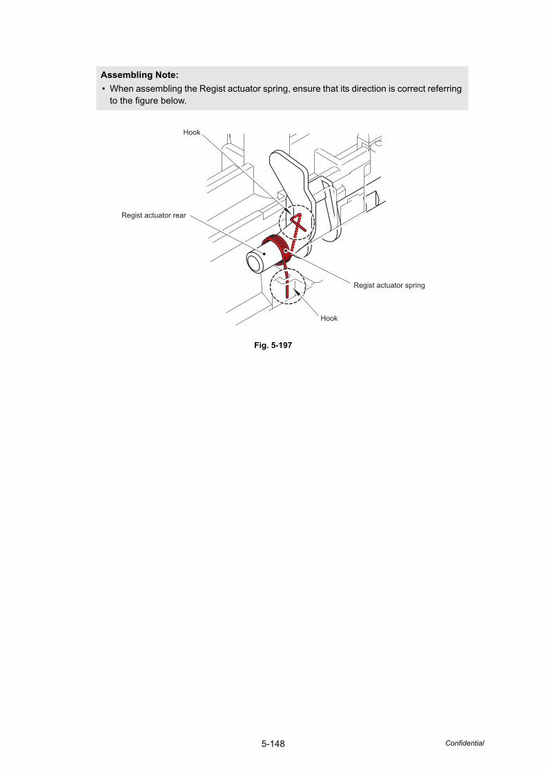
5-148 Confidential
Fig. 5-197
Assembling Note: • When assembling the Regist actuator spring, ensure that its direction is correct referring
to the figure below.
Hook
Regist actuator spring
Hook
Regist actuator rear
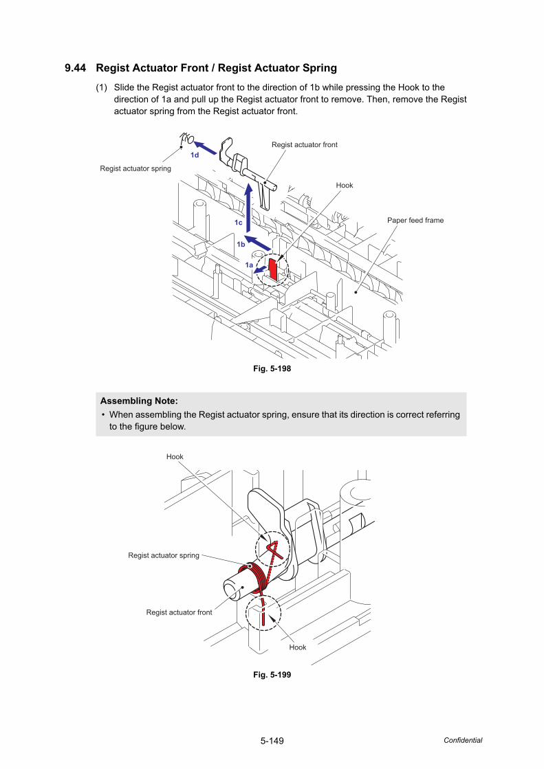
5-149 Confidential
9.44 Regist Actuator Front / Regist Actuator Spring(1) Slide the Regist actuator front to the direction of 1b while pressing the Hook to the
direction of 1a and pull up the Regist actuator front to remove. Then, remove the Regist actuator spring from the Regist actuator front.
Fig. 5-198
Fig. 5-199
Assembling Note: • When assembling the Regist actuator spring, ensure that its direction is correct referring
to the figure below.
Hook
Paper feed frame
Regist actuator front1d
1c
1b
1a
Regist actuator spring
Hook
Regist actuator spring
Hook
Regist actuator front
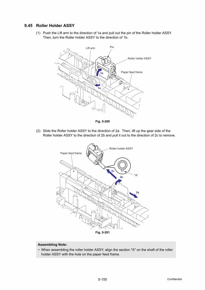
5-150 Confidential
9.45 Roller Holder ASSY(1) Push the Lift arm to the direction of 1a and pull out the pin of the Roller holder ASSY.
Then, turn the Roller holder ASSY to the direction of 1b.
Fig. 5-200
(2) Slide the Roller holder ASSY to the direction of 2a. Then, lift up the gear side of the Roller holder ASSY to the direction of 2b and pull it out to the direction of 2c to remove.
Fig. 5-201
Assembling Note: • When assembling the roller holder ASSY, align the section "A" on the shaft of the roller
holder ASSY with the hole on the paper feed frame.
Roller holder ASSY
1a
1b
Lift arm Pin
Paper feed frame
Roller holder ASSY
"A"2b
2a
2c
Paper feed frame
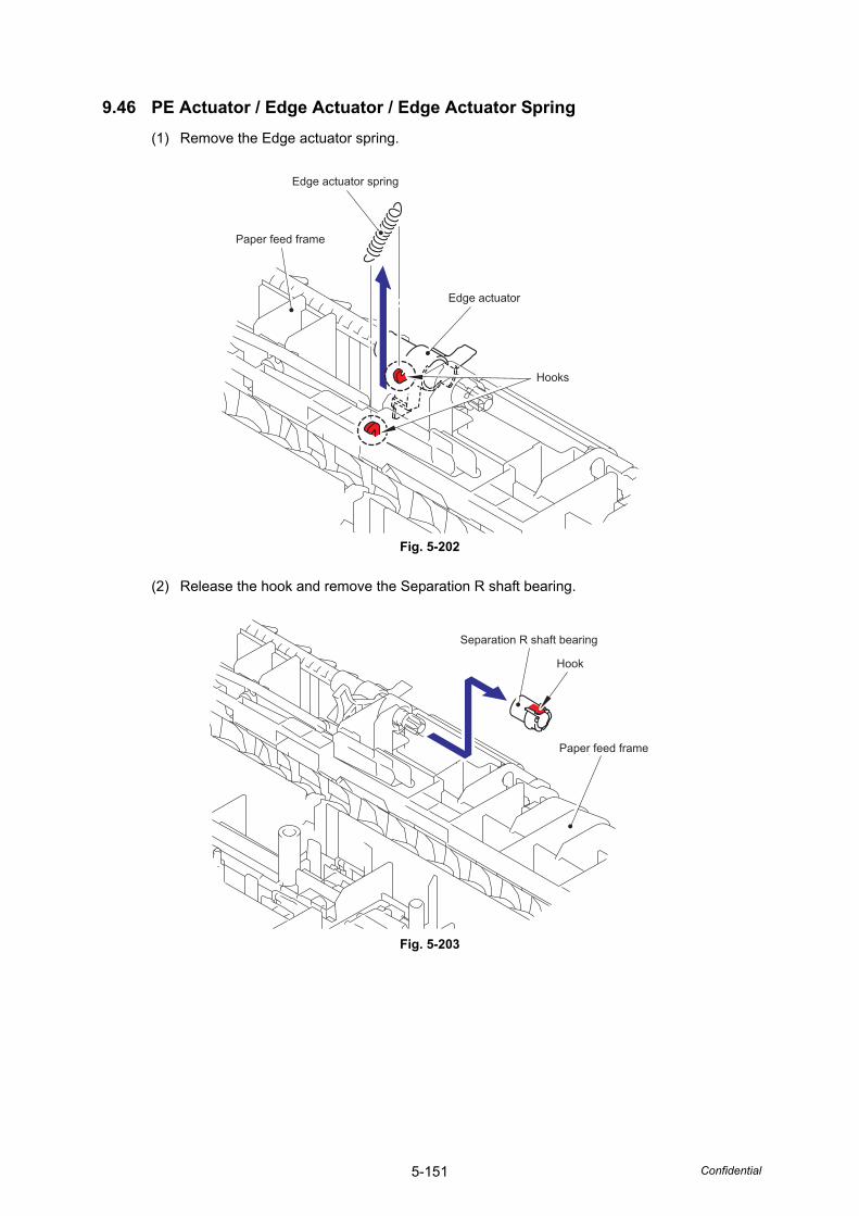
5-151 Confidential
9.46 PE Actuator / Edge Actuator / Edge Actuator Spring(1) Remove the Edge actuator spring.
Fig. 5-202
(2) Release the hook and remove the Separation R shaft bearing.
Fig. 5-203
Hooks
Edge actuator
Edge actuator spring
Paper feed frame
Hook
Paper feed frame
Separation R shaft bearing
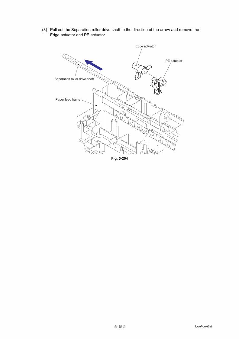
5-152 Confidential
(3) Pull out the Separation roller drive shaft to the direction of the arrow and remove the Edge actuator and PE actuator.
Fig. 5-204
PE actuator
Edge actuator
Separation roller drive shaft
Paper feed frame
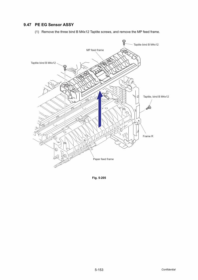
5-153 Confidential
9.47 PE EG Sensor ASSY(1) Remove the three bind B M4x12 Taptite screws, and remove the MP feed frame.
Fig. 5-205
Paper feed frame
Frame R
MP feed frame
Taptite bind B M4x12
Taptite bind B M4x12
Taptite, bind B M4x12
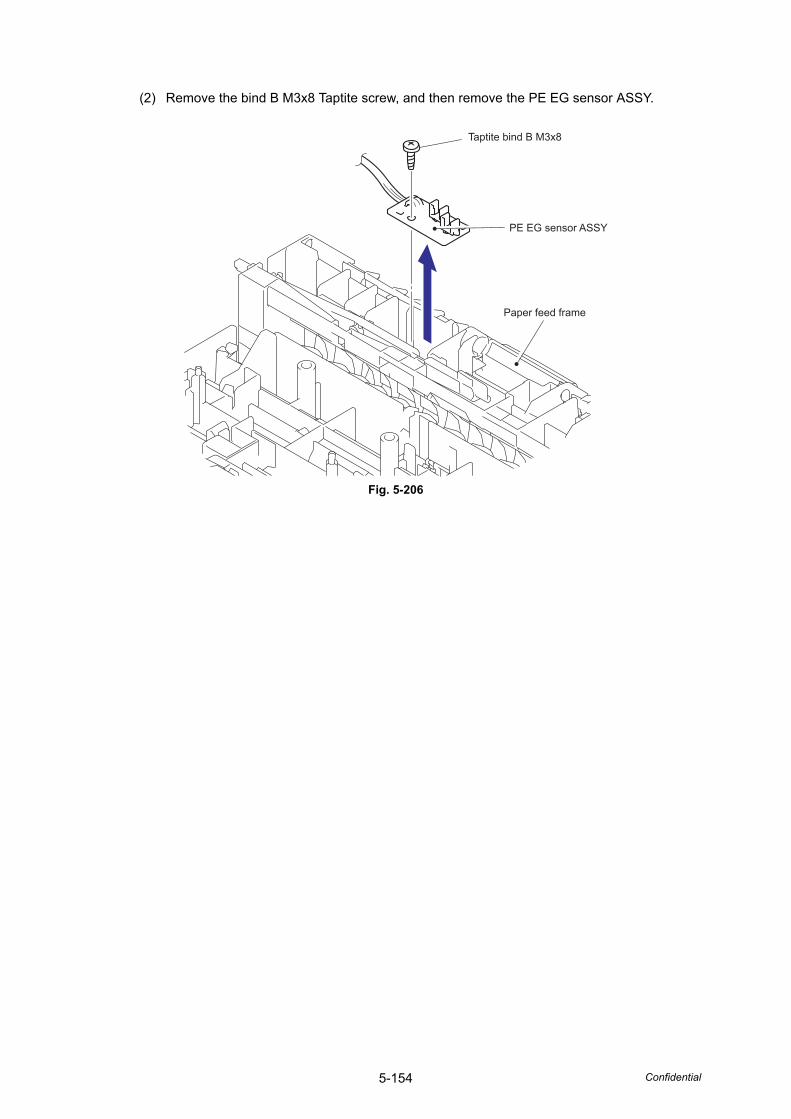
5-154 Confidential
(2) Remove the bind B M3x8 Taptite screw, and then remove the PE EG sensor ASSY.
Fig. 5-206
Paper feed frame
Taptite bind B M3x8
PE EG sensor ASSY
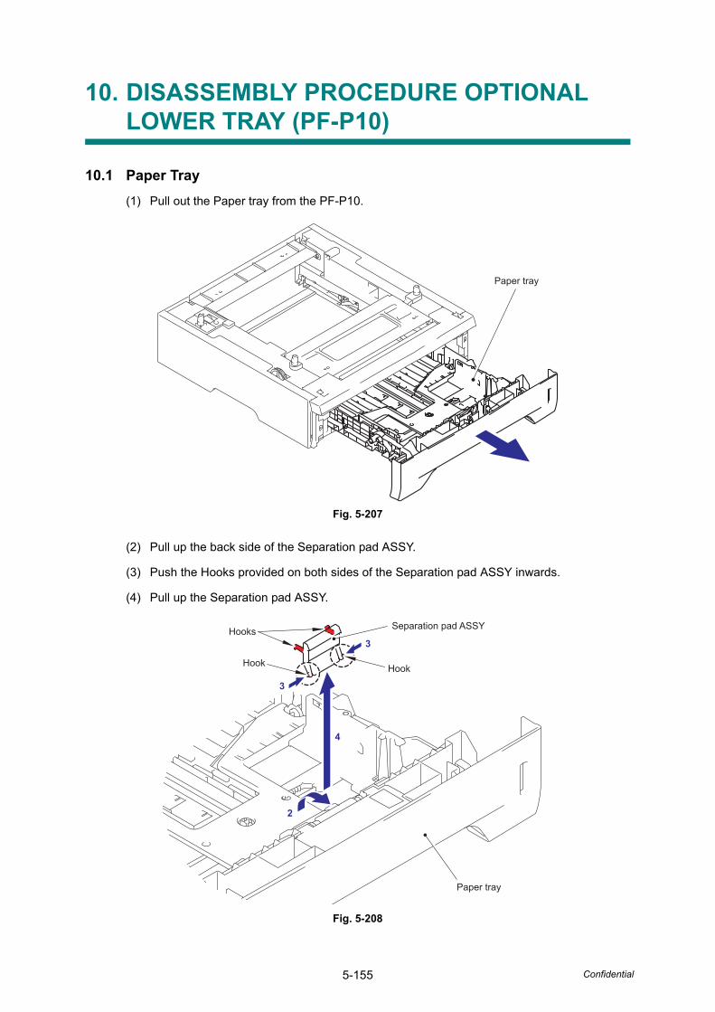
5-155 Confidential
10. DISASSEMBLY PROCEDURE OPTIONAL LOWER TRAY (PF-P10)
10.1 Paper Tray(1) Pull out the Paper tray from the PF-P10.
Fig. 5-207
(2) Pull up the back side of the Separation pad ASSY.
(3) Push the Hooks provided on both sides of the Separation pad ASSY inwards.
(4) Pull up the Separation pad ASSY.
Fig. 5-208
Paper tray
Paper tray
Hook
Hooks
Hook
Separation pad ASSY
3
3
4
2
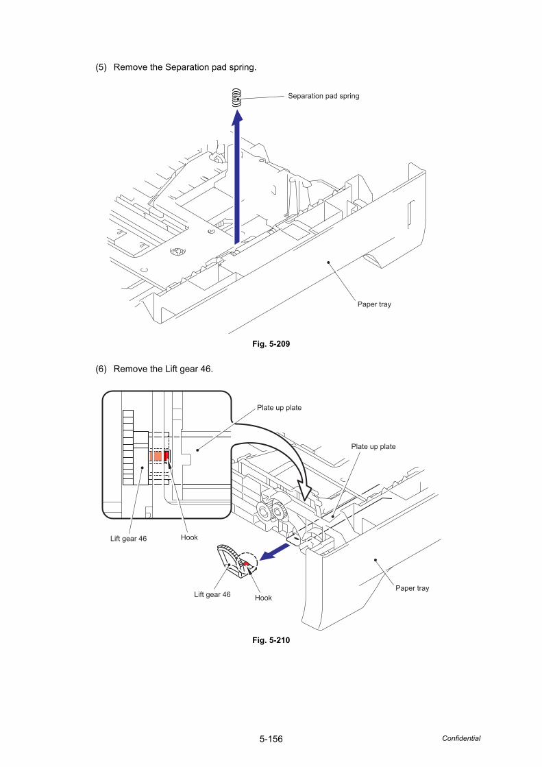
5-156 Confidential
(5) Remove the Separation pad spring.
Fig. 5-209
(6) Remove the Lift gear 46.
Fig. 5-210
Paper tray
Separation pad spring
Paper tray
Plate up plate
Plate up plate
Hook
HookLift gear 46
Lift gear 46
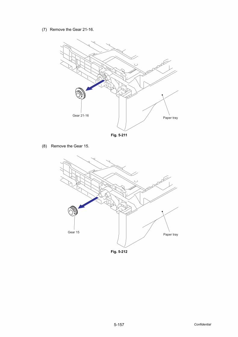
5-157 Confidential
(7) Remove the Gear 21-16.
Fig. 5-211
(8) Remove the Gear 15.
Fig. 5-212
Paper trayGear 21-16
Paper trayGear 15
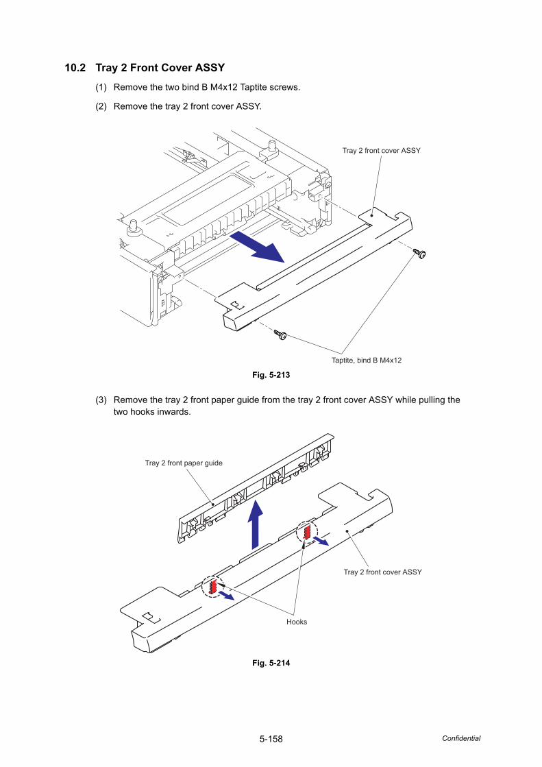
5-158 Confidential
10.2 Tray 2 Front Cover ASSY(1) Remove the two bind B M4x12 Taptite screws.
(2) Remove the tray 2 front cover ASSY.
Fig. 5-213
(3) Remove the tray 2 front paper guide from the tray 2 front cover ASSY while pulling the two hooks inwards.
Fig. 5-214
Taptite, bind B M4x12
Tray 2 front cover ASSY
Tray 2 front cover ASSY
Hooks
Tray 2 front paper guide
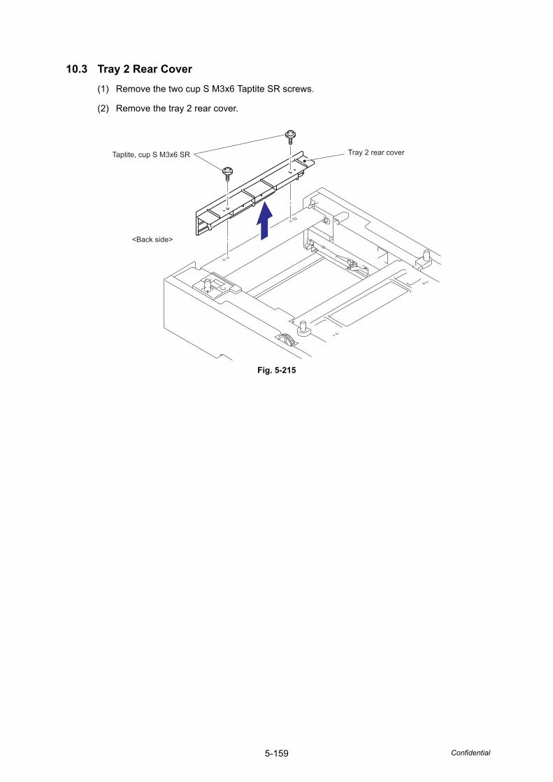
5-159 Confidential
10.3 Tray 2 Rear Cover(1) Remove the two cup S M3x6 Taptite SR screws.
(2) Remove the tray 2 rear cover.
Fig. 5-215
Tray 2 rear coverTaptite, cup S M3x6 SR
<Back side>
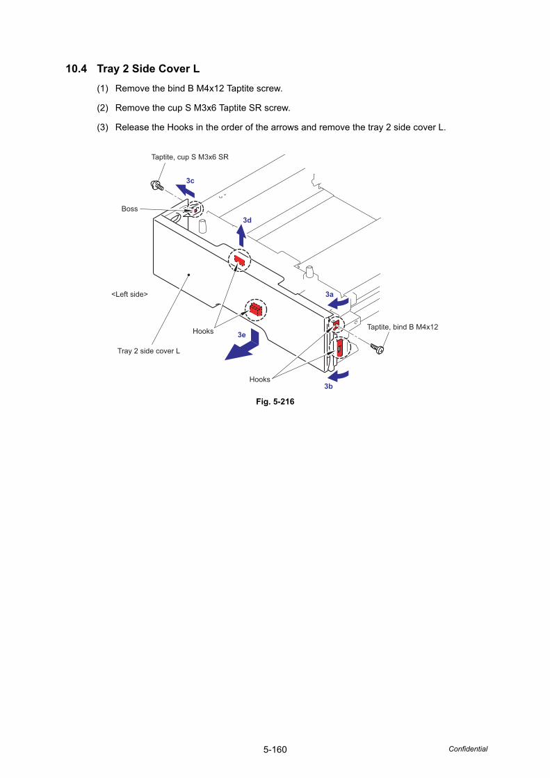
5-160 Confidential
10.4 Tray 2 Side Cover L(1) Remove the bind B M4x12 Taptite screw.
(2) Remove the cup S M3x6 Taptite SR screw.
(3) Release the Hooks in the order of the arrows and remove the tray 2 side cover L.
Fig. 5-216
Hooks
<Left side>
Hooks
Boss
Tray 2 side cover L
Taptite, bind B M4x12
Taptite, cup S M3x6 SR
3a
3b
3e
3d
3c
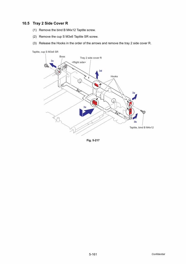
5-161 Confidential
10.5 Tray 2 Side Cover R(1) Remove the bind B M4x12 Taptite screw.
(2) Remove the cup S M3x6 Taptite SR screw.
(3) Release the Hooks in the order of the arrows and remove the tray 2 side cover R.
Fig. 5-217
<Right side>
Hooks
Boss Tray 2 side cover R
Taptite, bind B M4x12
Taptite, cup S M3x6 SR
3d
3c
3e
3b
3a
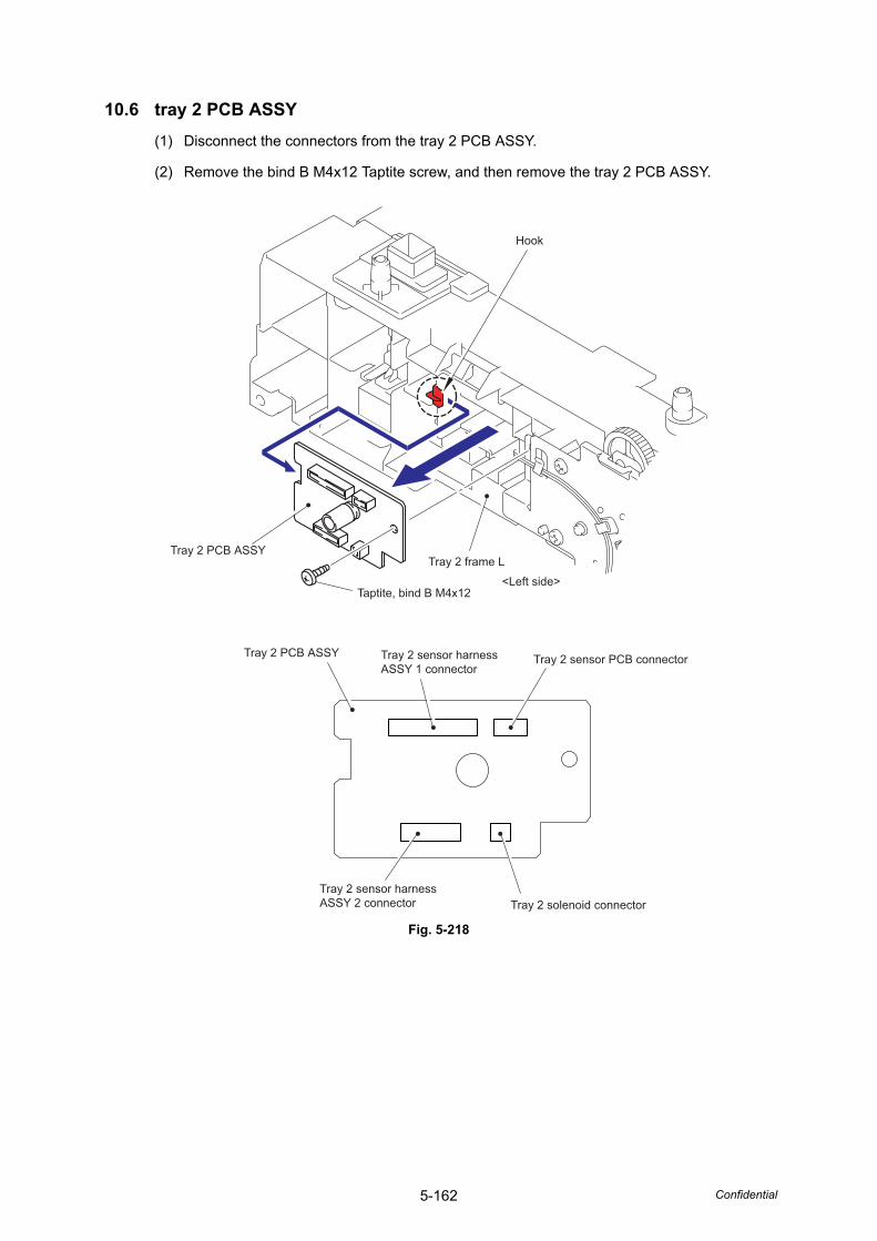
5-162 Confidential
10.6 tray 2 PCB ASSY(1) Disconnect the connectors from the tray 2 PCB ASSY.
(2) Remove the bind B M4x12 Taptite screw, and then remove the tray 2 PCB ASSY.
Fig. 5-218
<Left side>
Hook
Tray 2 PCB ASSYTray 2 frame L
Taptite, bind B M4x12
Tray 2 sensor PCB connector
Tray 2 solenoid connector
Tray 2 PCB ASSY Tray 2 sensor harness ASSY 1 connector
Tray 2 sensor harness ASSY 2 connector
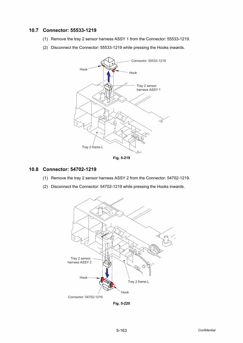
5-163 Confidential
10.7 Connector: 55533-1219(1) Remove the tray 2 sensor harness ASSY 1 from the Connector: 55533-1219.
(2) Disconnect the Connector: 55533-1219 while pressing the Hooks inwards.
Fig. 5-219
10.8 Connector: 54702-1219(1) Remove the tray 2 sensor harness ASSY 2 from the Connector: 54702-1219.
(2) Disconnect the Connector: 54702-1219 while pressing the Hooks inwards.
Fig. 5-220
HookHook
Tray 2 frame L
Tray 2 sensor harness ASSY 1
Connector: 55533-1219
Hook
HookTray 2 frame L
Tray 2 sensor harness ASSY 2
Connector: 54702-1219
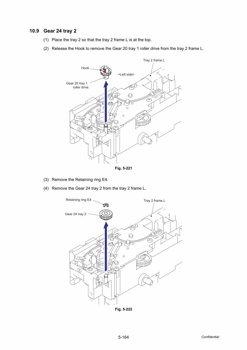
5-164 Confidential
10.9 Gear 24 tray 2(1) Place the tray 2 so that the tray 2 frame L is at the top.
(2) Release the Hook to remove the Gear 20 tray 1 roller drive from the tray 2 frame L.
Fig. 5-221
(3) Remove the Retaining ring E4.
(4) Remove the Gear 24 tray 2 from the tray 2 frame L.
Fig. 5-222
<Left side>
Hook
Gear 20 tray 1 roller drive
Tray 2 frame L
Retaining ring E4
Gear 24 tray 2
Tray 2 frame L
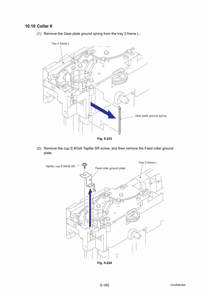
5-165 Confidential
10.10 Collar 6(1) Remove the Gear plate ground spring from the tray 2 frame L.
Fig. 5-223
(2) Remove the cup S M3x6 Taptite SR screw, and then remove the Feed roller ground plate.
Fig. 5-224
Gear plate ground spring
Tray 2 frame L
Taptite, cup S M3x6 SRTray 2 frame L
Feed roller ground plate
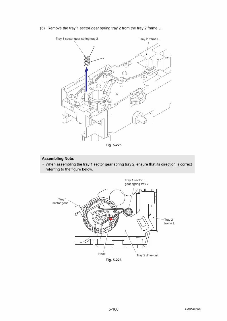
5-166 Confidential
(3) Remove the tray 1 sector gear spring tray 2 from the tray 2 frame L.
Fig. 5-225
Fig. 5-226
Assembling Note: • When assembling the tray 1 sector gear spring tray 2, ensure that its direction is correct
referring to the figure below.
Tray 2 frame LTray 1 sector gear spring tray 2
Tray 1 sector gear
Tray 1 sector gear spring tray 2
Tray 2 frame L
Tray 2 drive unitHook
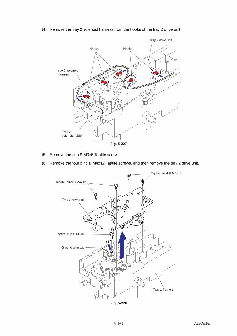
5-167 Confidential
(4) Remove the tray 2 solenoid harness from the hooks of the tray 2 drive unit.
Fig. 5-227
(5) Remove the cup S M3x6 Taptite screw.
(6) Remove the four bind B M4x12 Taptite screws, and then remove the tray 2 drive unit.
Fig. 5-228
Hooks
Tray 2 drive unit
Hooks
tray 2 solenoid harness
Tray 2 solenoid ASSY
Taptite, bind B M4x12
Taptite, bind B M4x12
Taptite, cup S M3x6
Tray 2 drive unit
Tray 2 frame L
Ground wire top
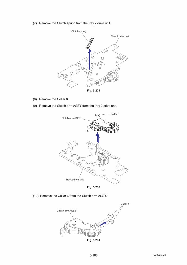
5-168 Confidential
(7) Remove the Clutch spring from the tray 2 drive unit.
Fig. 5-229
(8) Remove the Collar 6.
(9) Remove the Clutch arm ASSY from the tray 2 drive unit.
Fig. 5-230
(10) Remove the Collar 6 from the Clutch arm ASSY.
Fig. 5-231
Tray 2 drive unit
Clutch spring
Clutch arm ASSY
Tray 2 drive unit
Collar 6
Clutch arm ASSY
Collar 6
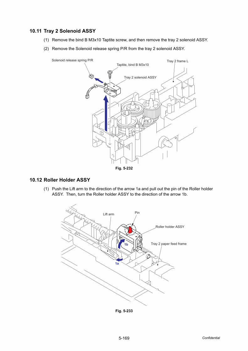
5-169 Confidential
10.11 Tray 2 Solenoid ASSY(1) Remove the bind B M3x10 Taptite screw, and then remove the tray 2 solenoid ASSY.
(2) Remove the Solenoid release spring P/R from the tray 2 solenoid ASSY.
Fig. 5-232
10.12 Roller Holder ASSY(1) Push the Lift arm to the direction of the arrow 1a and pull out the pin of the Roller holder
ASSY. Then, turn the Roller holder ASSY to the direction of the arrow 1b.
Fig. 5-233
Solenoid release spring P/RTaptite, bind B M3x10
Tray 2 solenoid ASSY
Tray 2 frame L
Lift arm Pin
Roller holder ASSY
Tray 2 paper feed frame1b
1a
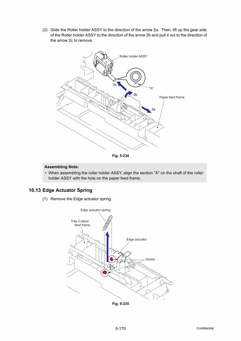
5-170 Confidential
(2) Slide the Roller holder ASSY to the direction of the arrow 2a. Then, lift up the gear side of the Roller holder ASSY to the direction of the arrow 2b and pull it out to the direction of the arrow 2c to remove.
Fig. 5-234
10.13 Edge Actuator Spring(1) Remove the Edge actuator spring.
Fig. 5-235
Assembling Note: • When assembling the roller holder ASSY, align the section "A" on the shaft of the roller
holder ASSY with the hole on the paper feed frame.
Roller holder ASSY
"A"
2a
2b
2c
Paper feed frame
Edge actuator spring
Edge actuator
Hooks
Tray 2 paper feed frame
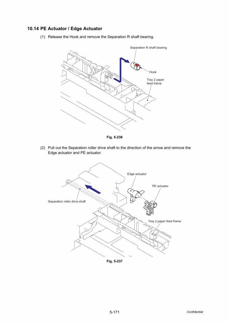
5-171 Confidential
10.14 PE Actuator / Edge Actuator(1) Release the Hook and remove the Separation R shaft bearing.
Fig. 5-236
(2) Pull out the Separation roller drive shaft to the direction of the arrow and remove the Edge actuator and PE actuator.
Fig. 5-237
Separation R shaft bearing
Hook
Tray 2 paper feed frame
Edge actuator
Separation roller drive shaft
PE actuator
Tray 2 paper feed frame
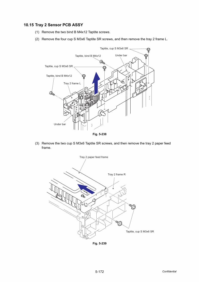
5-172 Confidential
10.15 Tray 2 Sensor PCB ASSY(1) Remove the two bind B M4x12 Taptite screws.
(2) Remove the four cup S M3x6 Taptite SR screws, and then remove the tray 2 frame L.
Fig. 5-238
(3) Remove the two cup S M3x6 Taptite SR screws, and then remove the tray 2 paper feed frame.
Fig. 5-239
Taptite, cup S M3x6 SR
Taptite, cup S M3x6 SR
Under bar
Under bar
Tray 2 frame L
Taptite, bind B M4x12
Taptite, bind B M4x12
Tray 2 paper feed frame
Tray 2 frame R
Taptite, cup S M3x6 SR
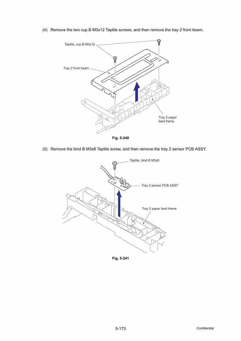
5-173 Confidential
(4) Remove the two cup B M3x12 Taptite screws, and then remove the tray 2 front beam.
Fig. 5-240
(5) Remove the bind B M3x8 Taptite screw, and then remove the tray 2 sensor PCB ASSY.
Fig. 5-241
Taptite, cup B M3x12
Tray 2 front beam
Tray 2 paper feed frame
Taptite, bind B M3x8
Tray 2 sensor PCB ASSY
Tray 2 paper feed frame

CHAPTER 6SERVICE MODE
Confidential
CHAPTER 6 SERVICE FUNCTIONS
The maintenance mode is exclusively designed for the purpose of checks, settings and adjustments using the buttons on the control panel or open/close of the front cover. You can perform operational checks of panel PCB, sensors, perform a print test, display the log information or error codes.
CONTENTS1. ENTRY INTO THE MAINTENANCE MODE..................................................................6-1
2. LIST OF MAINTENANCE-MODE FUNCTIONS ...........................................................6-2
3. USER-ACCESS TO THE MAINTENANCE MODE .......................................................6-3
4. DETAILED DESCRIPTION OF MAINTENANCE-MODE FUNCTIONS........................6-4
4.1 EEPROM Parameter Initialization (Function code 01/91) .....................................6-4
4.2 Printout of Scanning Compensation Data (Function code 05) ..............................6-5
4.3 Placement of Document Scanner Unit in Position for Transportation (Function code 06).................................................................................................6-8
4.4 ADF Performance Test (Function code 08) ...........................................................6-8
4.5 Test Pattern 1 (Function code 09) .........................................................................6-9
4.6 Firmware Switch Setting and Printout .................................................................6-10
4.6.1 Firmware switch setting (Function code 10).............................................6-10
4.6.2 Printout of firmware switch data (Function code 11) ................................6-14
4.7 Operation Check of LCD (Function code 12) ......................................................6-15
4.8 Operational Check of Control Panel Button (Function code 13)..........................6-16
4.9 ROM Version Check (Function code 25) .............................................................6-17
4.10 Sensor Operational Check (Function code 32) ...................................................6-18
4.11 PC Print Function (Function code 43) .................................................................6-20
4.12 Switching the USB Setting (Function code 45)....................................................6-23
4.13 EEPROM Customizing (User-accessible) (Function code 52) ............................6-24
4.14 Received Data Transfer Function (Function code 53) .........................................6-25
4.15 Fine Adjustment of Scan Start/End Positions (Function code 54) .......................6-27
4.16 Acquisition of White Level Data and CCD Scanner Area Setting (Function code 55)............................................6-29
4.17 Paper Feeding and Ejecting Test (Function code 67)..........................................6-31
4.18 EEPROM Customizing (Function code 74) .........................................................6-31
4.19 Operational Check of Fans (Function code 78)...................................................6-33
4.20 Display of the Machine’s Log Information (Function code 80).............................6-34
4.21 Error Code Indication (Function code 82)............................................................6-36
4.22 Output of Transmission Log to the Telephone Line (Function code 87) ..............6-36
4.23 Counter Reset After Replacing the Fuser Unit,Laser Unit and Paper Feed Kit (Function code 88) .............................................6-37
4.24 Maintenance Mode Finish (Function code 99) ....................................................6-37

Confidential
5. OTHER SERVICE FUNCTIONS .................................................................................6-38
5.1 Resetting the Periodical Maintenance Parts Life.................................................6-38
5.2 Develop Roller / Developing Bias Voltage Counter Reset Function ....................6-40
5.3 Drum condensation countermeasure mode ........................................................6-41
5.4 Unlocking and Clearing the Password of the Function Lock / Setting Lock ........6-41
5.5 Clearing the Data of the Secure Print..................................................................6-41
6-1 Confidential
1. ENTRY INTO THE MAINTENANCE MODE
Press the [Menu], [Start] ,and [ ] button four times quickly in this order to make the machine enter the maintenance mode.
The machine beeps for approx. one second and displays " " on the LCD, indicating that it is placed in the initial stage of the maintenance mode, a mode in which the machine is ready to accept entry from the buttons.
To select one of the maintenance-mode functions listed in "2. LIST OF MAINTENANCE-MODE FUNCTIONS", press the [ ] button or [ ] button to display any function code on the LCD. Then press the [OK] button.(The details of each maintenance-mode function are described in "4. DETAILED DESCRIPTION OF MAINTENANCE-MODE FUNCTIONS".)
Note:• To exit from the maintenance mode and switch to standby, press the [9] key twice in
the initial stage of the maintenance mode.
• Pressing the [Stop/Exit] button after entering only one digit restores the machine to the initial stage of the maintenance mode.
• If an invalid function code is entered, the machine resumes the initial stage of the maintenance mode.
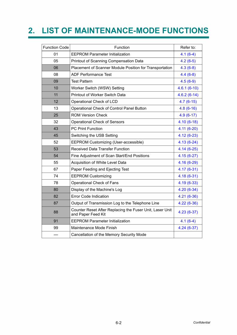
6-2 Confidential
2. LIST OF MAINTENANCE-MODE FUNCTIONS
Function Code Function Refer to:
01 EEPROM Parameter Initialization 4.1 (6-4)
05 Printout of Scanning Compensation Data 4.2 (6-5)
06 Placement of Scanner Module Position for Transportation 4.3 (6-8)
08 ADF Performance Test 4.4 (6-8)
09 Test Pattern 4.5 (6-9)
10 Worker Switch (WSW) Setting 4.6.1 (6-10)
11 Printout of Worker Switch Data 4.6.2 (6-14)
12 Operational Check of LCD 4.7 (6-15)
13 Operational Check of Control Panel Button 4.8 (6-16)
25 ROM Version Check 4.9 (6-17)
32 Operational Check of Sensors 4.10 (6-18)
43 PC Print Function 4.11 (6-20)
45 Switching the USB Setting 4.12 (6-23)
52 EEPROM Customizing (User-accessible) 4.13 (6-24)
53 Received Data Transfer Function 4.14 (6-25)
54 Fine Adjustment of Scan Start/End Positions 4.15 (6-27)
55 Acquisition of White Level Data 4.16 (6-29)
67 Paper Feeding and Ejecting Test 4.17 (6-31)
74 EEPROM Customizing 4.18 (6-31)
78 Operational Check of Fans 4.19 (6-33)
80 Display of the Machine's Log 4.20 (6-34)
82 Error Code Indication 4.21 (6-36)
87 Output of Transmission Log to the Telephone Line 4.22 (6-36)
88 Counter Reset After Replacing the Fuser Unit, Laser Unit and Paper Feed Kit 4.23 (6-37)
91 EEPROM Parameter Initialization 4.1 (6-4)
99 Maintenance Mode Finish 4.24 (6-37)
- Cancellation of the Memory Security Mode
6-3 Confidential
3. USER-ACCESS TO THE MAINTENANCE MODE
Basically, the maintenance-mode functions listed on the previous page should be accessed by service personnel only. However, you can allow end users to access some of these under the guidance of service personnel (e.g., by telephone).
The user-accessible functions (codes 06, 09, 10, 11, 12, 25, 45, 53, 54, 80, 82, 87 and 88) are shaded in the table given on the previous page. Function code 10 accesses the firmware switches, each of which has eight selectors. You should not allow end users to access all of those selectors, but you can allow them to access user-accessible selectors which are shaded in the firmware switch tables in APPENDIX 1.
The service personnel should instruct end users to follow the procedure given below.
(1) Press the [Menu], [Start], [Menu], and [ ] buttons in this order.The "MAINTENANCE 10" appears on the LCD.
(2) Press the [ ] button or [ ] button several times to display the desired maintenance code on the LCD.Then press the [OK] button.
(3) To switch the machine back to the standby state, press the [Stop/Exit] button. When each of the user-accessible functions is completed, the machine automatically returns to the standby state.
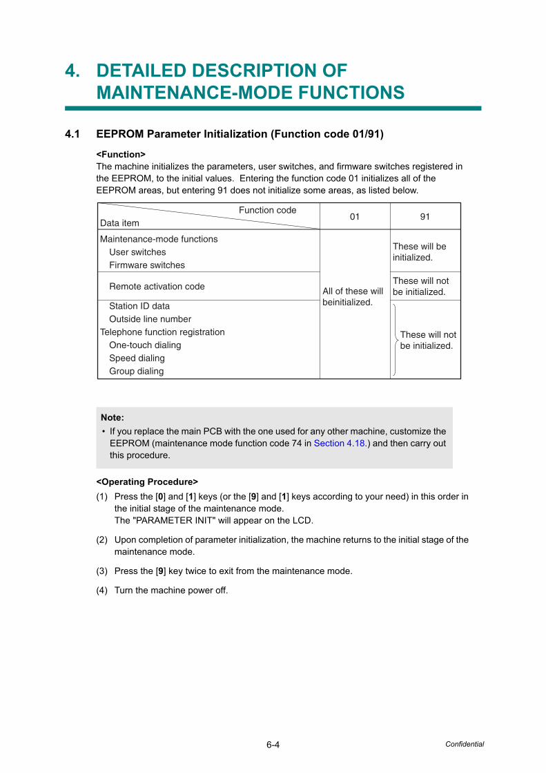
6-4 Confidential
4. DETAILED DESCRIPTION OF MAINTENANCE-MODE FUNCTIONS
4.1 EEPROM Parameter Initialization (Function code 01/91)
<Function>The machine initializes the parameters, user switches, and firmware switches registered in the EEPROM, to the initial values. Entering the function code 01 initializes all of the EEPROM areas, but entering 91 does not initialize some areas, as listed below.
<Operating Procedure>(1) Press the [0] and [1] keys (or the [9] and [1] keys according to your need) in this order in
the initial stage of the maintenance mode.The "PARAMETER INIT" will appear on the LCD.
(2) Upon completion of parameter initialization, the machine returns to the initial stage of the maintenance mode.
(3) Press the [9] key twice to exit from the maintenance mode.
(4) Turn the machine power off.
Note:• If you replace the main PCB with the one used for any other machine, customize the
EEPROM (maintenance mode function code 74 in Section 4.18.) and then carry out this procedure.
Function codeData item
01 91
Maintenance-mode functionsUser switchesFirmware switches
Remote activation code
Station ID dataOutside line number
Telephone function registrationOne-touch dialingSpeed dialingGroup dialing
All of these will beinitialized.
These will be initialized.
These will not be initialized.
These will not be initialized.
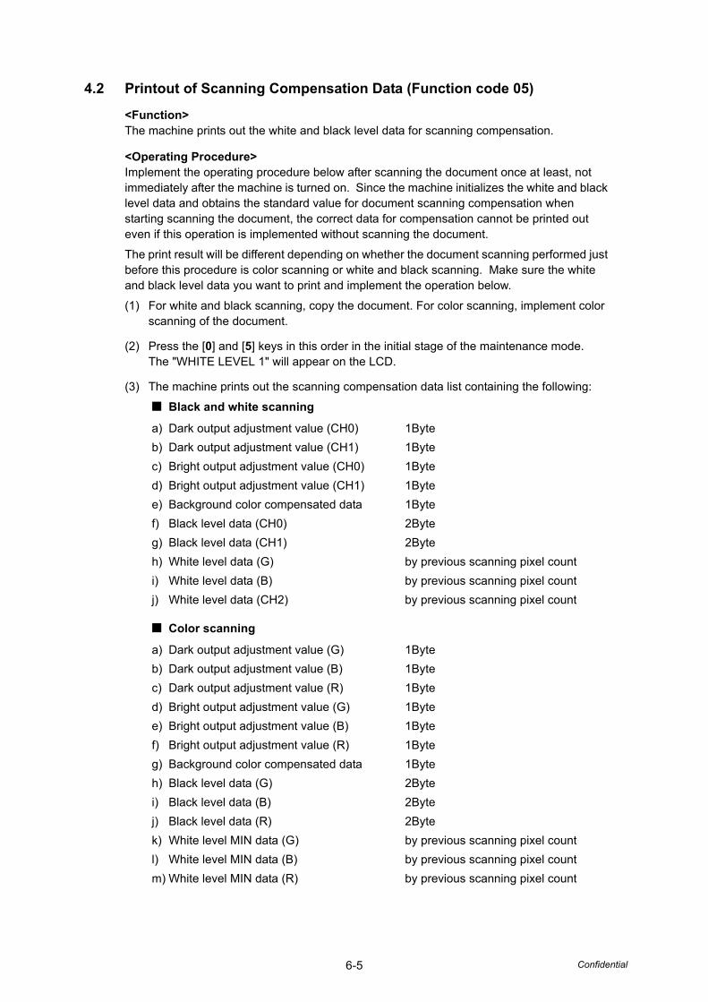
6-5 Confidential
4.2 Printout of Scanning Compensation Data (Function code 05)
<Function>The machine prints out the white and black level data for scanning compensation.
<Operating Procedure>Implement the operating procedure below after scanning the document once at least, not immediately after the machine is turned on. Since the machine initializes the white and black level data and obtains the standard value for document scanning compensation when starting scanning the document, the correct data for compensation cannot be printed out even if this operation is implemented without scanning the document.
The print result will be different depending on whether the document scanning performed just before this procedure is color scanning or white and black scanning. Make sure the white and black level data you want to print and implement the operation below.
(1) For white and black scanning, copy the document. For color scanning, implement color scanning of the document.
(2) Press the [0] and [5] keys in this order in the initial stage of the maintenance mode.The "WHITE LEVEL 1" will appear on the LCD.
(3) The machine prints out the scanning compensation data list containing the following:
■ Black and white scanning
■ Color scanning
a) Dark output adjustment value (CH0) 1Byteb) Dark output adjustment value (CH1) 1Bytec) Bright output adjustment value (CH0) 1Byted) Bright output adjustment value (CH1) 1Bytee) Background color compensated data 1Bytef) Black level data (CH0) 2Byteg) Black level data (CH1) 2Byteh) White level data (G) by previous scanning pixel counti) White level data (B) by previous scanning pixel countj) White level data (CH2) by previous scanning pixel count
a) Dark output adjustment value (G) 1Byteb) Dark output adjustment value (B) 1Bytec) Dark output adjustment value (R) 1Byted) Bright output adjustment value (G) 1Bytee) Bright output adjustment value (B) 1Bytef) Bright output adjustment value (R) 1Byteg) Background color compensated data 1Byteh) Black level data (G) 2Bytei) Black level data (B) 2Bytej) Black level data (R) 2Bytek) White level MIN data (G) by previous scanning pixel countl) White level MIN data (B) by previous scanning pixel countm) White level MIN data (R) by previous scanning pixel count
6-6 Confidential
(4) Upon completion of printing of the compensation data list, the machine returns to the initial stage of the maintenance mode.
■ For white and black scanning
Fig. 6-1
Note:• If any data is abnormal, its code will be printed in inline style.
6-7 Confidential
■ For color scanning
Fig. 6-2
6-8 Confidential
4.3 Placement of Document Scanner Unit in Position for Transportation (Function code 06)
<Function>This function is to move the document scanner unit in position for transportation located at the left end.When you fix the FAX equipment and check its operation, you need to perform this function right before packing and shipping it.
<Operating Procedure>
(1) Press the [0] and [6] keys in this order in the initial stage of the maintenance mode.The CCD unit moves to the designated position for transportation located at the left end. The "MAINTENANCE 06" is displayed until the CCD unit is placed in position.When the CCD unit is placed in the position, the "PLEASE SCAN LOCK" appears on the LCD.
(2) Open the document cover, and lock the scanner lock lever at the rear left of the document scanner unit. When the scanner lock lever is locked, the "SCAN LOCKED" appears. To terminate this operation, press the [Stop/Exit] button. The machine returns to the initial stage of the maintenance mode. The machine will be unable to scan after this operation until switch OFF/ON is pressed or the "Function 99" is performed.
4.4 ADF Performance Test (Function code 08)
<Function>The machine counts the documents fed by the automatic document feeder (ADF) and displays the count on the LCD for checking the ADF performance.
<Operating Procedure>(1) Set documents. (Allowable up to the ADF capacity.)
The "DOC. READY" will appear on the LCD.
(2) Press the [0] and [8] keys in this order.Press the [ ] or [ ] buttons so that the "[ ]: DX, [ ]: SX" is displayed on the LCD.While counting the documents, the machine feeds them in and out, displaying the current count on the LCD as shown below.
(3) Press the [Stop/Exit] button, then the operation of the above will finish and return the machine to the initial stage of the maintenance mode.
Note:• Please instruct end users to perform this function if possible before packing and
shipping their FAX equipment to a sales agent or a service dealer for the purpose of repair. (For the procedure to allow users to perform maintenance modes, please see Section 3.)
ADF CHECK P.01
Current count (1st page in this example)
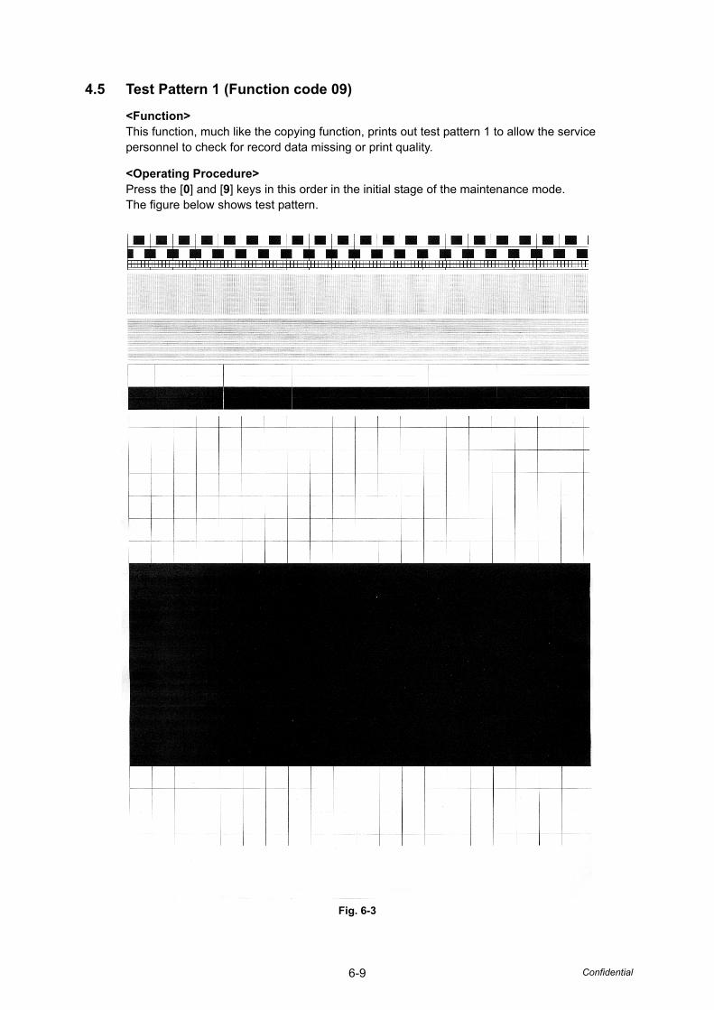
6-9 Confidential
4.5 Test Pattern 1 (Function code 09)
<Function>This function, much like the copying function, prints out test pattern 1 to allow the service personnel to check for record data missing or print quality.
<Operating Procedure>Press the [0] and [9] keys in this order in the initial stage of the maintenance mode.The figure below shows test pattern.
Fig. 6-3
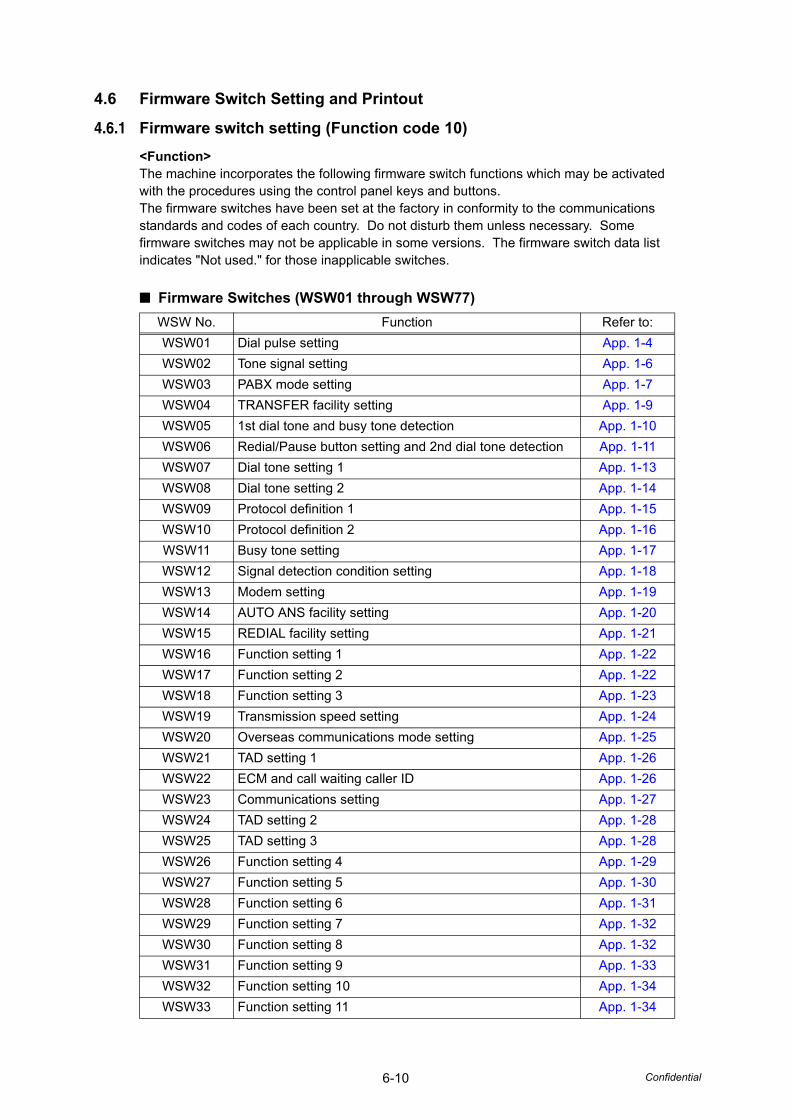
6-10 Confidential
4.6 Firmware Switch Setting and Printout
4.6.1 Firmware switch setting (Function code 10)<Function>The machine incorporates the following firmware switch functions which may be activated with the procedures using the control panel keys and buttons.The firmware switches have been set at the factory in conformity to the communications standards and codes of each country. Do not disturb them unless necessary. Some firmware switches may not be applicable in some versions. The firmware switch data list indicates "Not used." for those inapplicable switches.
■ Firmware Switches (WSW01 through WSW77)WSW No. Function Refer to:WSW01 Dial pulse setting App. 1-4WSW02 Tone signal setting App. 1-6WSW03 PABX mode setting App. 1-7WSW04 TRANSFER facility setting App. 1-9WSW05 1st dial tone and busy tone detection App. 1-10WSW06 Redial/Pause button setting and 2nd dial tone detection App. 1-11WSW07 Dial tone setting 1 App. 1-13WSW08 Dial tone setting 2 App. 1-14WSW09 Protocol definition 1 App. 1-15WSW10 Protocol definition 2 App. 1-16WSW11 Busy tone setting App. 1-17WSW12 Signal detection condition setting App. 1-18WSW13 Modem setting App. 1-19WSW14 AUTO ANS facility setting App. 1-20WSW15 REDIAL facility setting App. 1-21WSW16 Function setting 1 App. 1-22WSW17 Function setting 2 App. 1-22WSW18 Function setting 3 App. 1-23WSW19 Transmission speed setting App. 1-24WSW20 Overseas communications mode setting App. 1-25WSW21 TAD setting 1 App. 1-26WSW22 ECM and call waiting caller ID App. 1-26WSW23 Communications setting App. 1-27WSW24 TAD setting 2 App. 1-28WSW25 TAD setting 3 App. 1-28WSW26 Function setting 4 App. 1-29WSW27 Function setting 5 App. 1-30WSW28 Function setting 6 App. 1-31WSW29 Function setting 7 App. 1-32WSW30 Function setting 8 App. 1-32WSW31 Function setting 9 App. 1-33WSW32 Function setting 10 App. 1-34WSW33 Function setting 11 App. 1-34
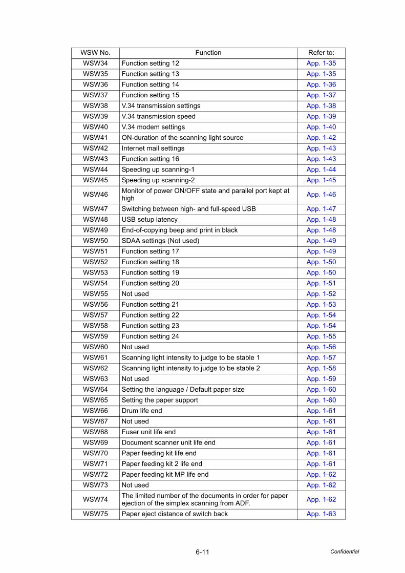
6-11 Confidential
WSW34 Function setting 12 App. 1-35WSW35 Function setting 13 App. 1-35WSW36 Function setting 14 App. 1-36WSW37 Function setting 15 App. 1-37WSW38 V.34 transmission settings App. 1-38WSW39 V.34 transmission speed App. 1-39WSW40 V.34 modem settings App. 1-40WSW41 ON-duration of the scanning light source App. 1-42WSW42 Internet mail settings App. 1-43WSW43 Function setting 16 App. 1-43WSW44 Speeding up scanning-1 App. 1-44WSW45 Speeding up scanning-2 App. 1-45
WSW46 Monitor of power ON/OFF state and parallel port kept at high App. 1-46
WSW47 Switching between high- and full-speed USB App. 1-47WSW48 USB setup latency App. 1-48WSW49 End-of-copying beep and print in black App. 1-48WSW50 SDAA settings (Not used) App. 1-49WSW51 Function setting 17 App. 1-49WSW52 Function setting 18 App. 1-50WSW53 Function setting 19 App. 1-50WSW54 Function setting 20 App. 1-51WSW55 Not used App. 1-52WSW56 Function setting 21 App. 1-53WSW57 Function setting 22 App. 1-54WSW58 Function setting 23 App. 1-54WSW59 Function setting 24 App. 1-55WSW60 Not used App. 1-56WSW61 Scanning light intensity to judge to be stable 1 App. 1-57WSW62 Scanning light intensity to judge to be stable 2 App. 1-58WSW63 Not used App. 1-59WSW64 Setting the language / Default paper size App. 1-60WSW65 Setting the paper support App. 1-60WSW66 Drum life end App. 1-61WSW67 Not used App. 1-61WSW68 Fuser unit life end App. 1-61WSW69 Document scanner unit life end App. 1-61WSW70 Paper feeding kit life end App. 1-61WSW71 Paper feeding kit 2 life end App. 1-61WSW72 Paper feeding kit MP life end App. 1-62WSW73 Not used App. 1-62
WSW74 The limited number of the documents in order for paper ejection of the simplex scanning from ADF. App. 1-62
WSW75 Paper eject distance of switch back App. 1-63
WSW No. Function Refer to:

6-12 Confidential
WSW76 The limited number of the documents in reverse for paper ejection of the simplex scanning from ADF. App. 1-64
WSW77 The limited number of the documents in reverse for paper ejection of the duplex scanning from ADF. App. 1-64
WSW No. Function Refer to:
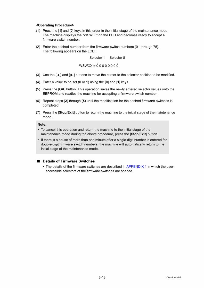
6-13 Confidential
<Operating Procedure>(1) Press the [1] and [0] keys in this order in the initial stage of the maintenance mode.
The machine displays the "WSW00" on the LCD and becomes ready to accept a firmware switch number.
(2) Enter the desired number from the firmware switch numbers (01 through 75).The following appears on the LCD:
(3) Use the [ ] and [ ] buttons to move the cursor to the selector position to be modified.
(4) Enter a value to be set (0 or 1) using the [0] and [1] keys.
(5) Press the [OK] button. This operation saves the newly entered selector values onto the EEPROM and readies the machine for accepting a firmware switch number.
(6) Repeat steps (2) through (5) until the modification for the desired firmware switches is completed.
(7) Press the [Stop/Exit] button to return the machine to the initial stage of the maintenance mode.
■ Details of Firmware Switches• The details of the firmware switches are described in APPENDIX 1 in which the user-
accessible selectors of the firmware switches are shaded.
Note:• To cancel this operation and return the machine to the initial stage of the
maintenance mode during the above procedure, press the [Stop/Exit] button.
• If there is a pause of more than one minute after a single-digit number is entered for double-digit firmware switch numbers, the machine will automatically return to the initial stage of the maintenance mode.
Selector 1 Selector 8
WSWXX = 0 0 0 0 0 0 0 0
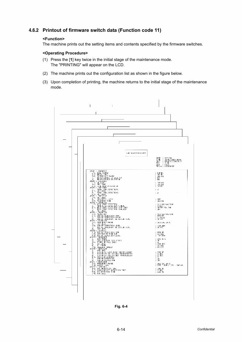
6-14 Confidential
4.6.2 Printout of firmware switch data (Function code 11)<Function>The machine prints out the setting items and contents specified by the firmware switches.
<Operating Procedure>(1) Press the [1] key twice in the initial stage of the maintenance mode.
The "PRINTING" will appear on the LCD.
(2) The machine prints out the configuration list as shown in the figure below.
(3) Upon completion of printing, the machine returns to the initial stage of the maintenance mode.
Fig. 6-4
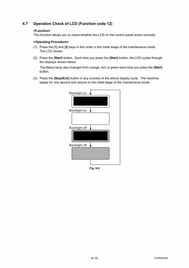
6-15 Confidential
4.7 Operation Check of LCD (Function code 12)
<Function>This function allows you to check whether the LCD on the control panel works normally.
<Operating Procedure>(1) Press the [1] and [2] keys in this order in the initial stage of the maintenance mode.
The LCD shows.
(2) Press the [Start] button. Each time you press the [Start] button, the LCD cycles through the displays shown below.
The Status lamp also changes from orange, red, to green each time you press the [Start] button.
(3) Press the [Stop/Exit] button in any process of the above display cycle. The machine beeps for one second and returns to the initial stage of the maintenance mode.
Fig. 6-5
Backlight on
Backlight on
Backlight off
Backlight off
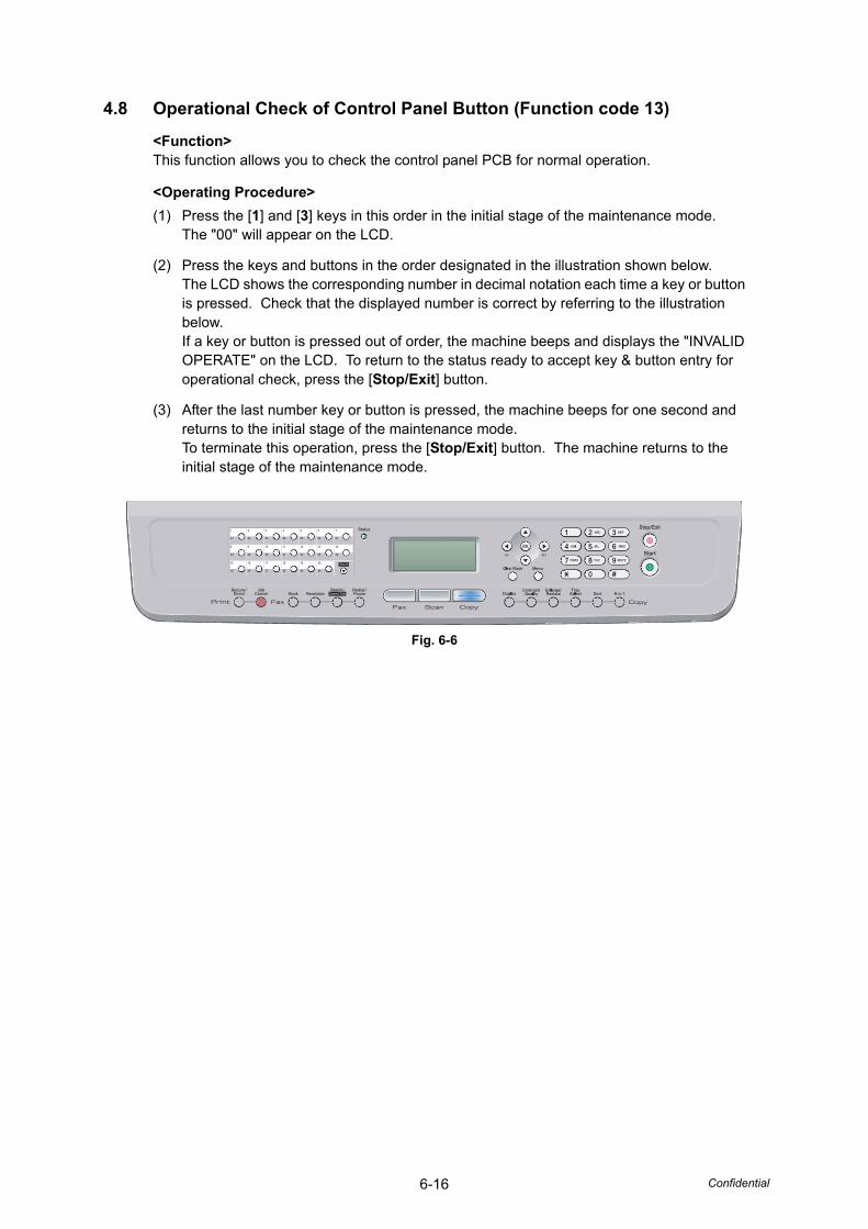
6-16 Confidential
4.8 Operational Check of Control Panel Button (Function code 13)
<Function>This function allows you to check the control panel PCB for normal operation.
<Operating Procedure>(1) Press the [1] and [3] keys in this order in the initial stage of the maintenance mode.
The "00" will appear on the LCD.
(2) Press the keys and buttons in the order designated in the illustration shown below.The LCD shows the corresponding number in decimal notation each time a key or button is pressed. Check that the displayed number is correct by referring to the illustration below.If a key or button is pressed out of order, the machine beeps and displays the "INVALID OPERATE" on the LCD. To return to the status ready to accept key & button entry for operational check, press the [Stop/Exit] button.
(3) After the last number key or button is pressed, the machine beeps for one second and returns to the initial stage of the maintenance mode.To terminate this operation, press the [Stop/Exit] button. The machine returns to the initial stage of the maintenance mode.
Fig. 6-6
6-17 Confidential
4.9 ROM Version Check (Function code 25)
<Function>This function allows you to check the management information of the software programs such as version information, check sum.
<Operating Procedure>(1) Press the [2] key and [5] key in this order in the initial stage of the maintenance mode.
The machine displays each of terms described below on the LCD.
(2) Press the [ ] or [ ] button to check the next term.
*1 I-FAX firmware version does not display on the LCD, if you have not downloaded the I-FAX.
*2 In the case of the model without Demo data, the “D·········· : ····” displayed on the LCD.
*3 To perform the ROM Check Sum, press the [OK] button during the "ROM Check Sum" is displayed on the LCD. If the calculation result of the check sum is correct, "ROM Check Sum OK" will be displayed on the LCD, otherwise "ROM Check Sum NG" will be displayed on the LCD.
• How to display the check sum informationTerms displayed with “*” have the check sum information as well. Press the [OK] button when its version information is displayed on the LCD. Press the [OK] button again to go back to the version information display. Press the [ ] or [ ] buttons to check the next term.
(3) To terminate this operation, press the [Stop/Exit] button. The machine beeps for one second and returns to the initial stage of the maintenance mode.
LCD Description
TOTAL: Ver A* Main firmware version information (Revision information)
PCL : Ver1.00* Sub firmware (PCL/PS) version information (ROM size)
NET : Ver1.00 Network version information
PANEL : A08103015 Panel firmware version information
i0802312359: 1234* *1 I-FAX firmware version information
B0808071049:5708* Boot program creation date & check sum information
U0812271600:7B0A* Main firmware creation date & check sum information
D0812312359: 1234* *2 Demo program creation date & check sum information
P0812271602:BD40* Sub firmware (PCL/PS) creation date & check sum information
ROM Check Sum *3 Calculate the check sum information of the main and PCL and display the “OK” if right.
Note:• Even if you press the [OK] button when each version information of Engine,
Network and Panel is displayed on the LCD, you cannot check the check sum information.
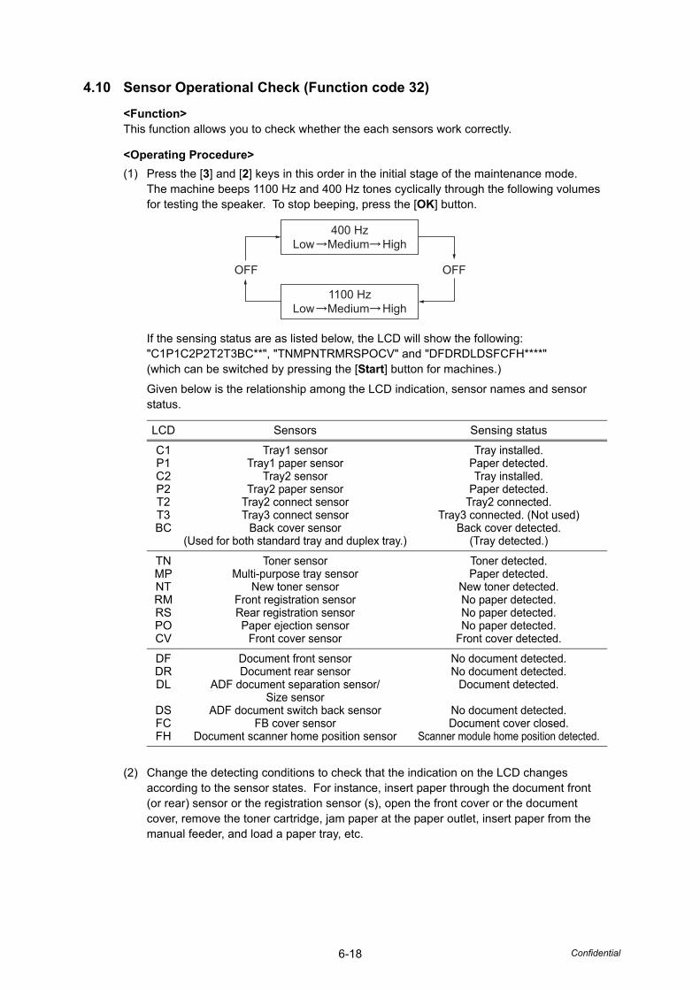
6-18 Confidential
4.10 Sensor Operational Check (Function code 32)
<Function>This function allows you to check whether the each sensors work correctly.
<Operating Procedure>(1) Press the [3] and [2] keys in this order in the initial stage of the maintenance mode.
The machine beeps 1100 Hz and 400 Hz tones cyclically through the following volumes for testing the speaker. To stop beeping, press the [OK] button.
If the sensing status are as listed below, the LCD will show the following:"C1P1C2P2T2T3BC**", "TNMPNTRMRSPOCV" and "DFDRDLDSFCFH****" (which can be switched by pressing the [Start] button for machines.)
Given below is the relationship among the LCD indication, sensor names and sensor status.
(2) Change the detecting conditions to check that the indication on the LCD changes according to the sensor states. For instance, insert paper through the document front (or rear) sensor or the registration sensor (s), open the front cover or the document cover, remove the toner cartridge, jam paper at the paper outlet, insert paper from the manual feeder, and load a paper tray, etc.
LCD Sensors Sensing status
C1P1C2P2T2T3BC
Tray1 sensorTray1 paper sensor
Tray2 sensorTray2 paper sensor
Tray2 connect sensorTray3 connect sensor
Back cover sensor(Used for both standard tray and duplex tray.)
Tray installed.Paper detected.Tray installed.
Paper detected.Tray2 connected.
Tray3 connected. (Not used)Back cover detected.
(Tray detected.)
TNMPNTRMRSPOCV
Toner sensorMulti-purpose tray sensor
New toner sensorFront registration sensorRear registration sensorPaper ejection sensor
Front cover sensor
Toner detected.Paper detected.
New toner detected.No paper detected.No paper detected.No paper detected.
Front cover detected.
DFDRDL
DSFCFH
Document front sensor Document rear sensor
ADF document separation sensor/Size sensor
ADF document switch back sensorFB cover sensor
Document scanner home position sensor
No document detected.No document detected.
Document detected.
No document detected.Document cover closed.
Scanner module home position detected.
400 HzLow Medium High
OFF OFF
1100 HzLow Medium High
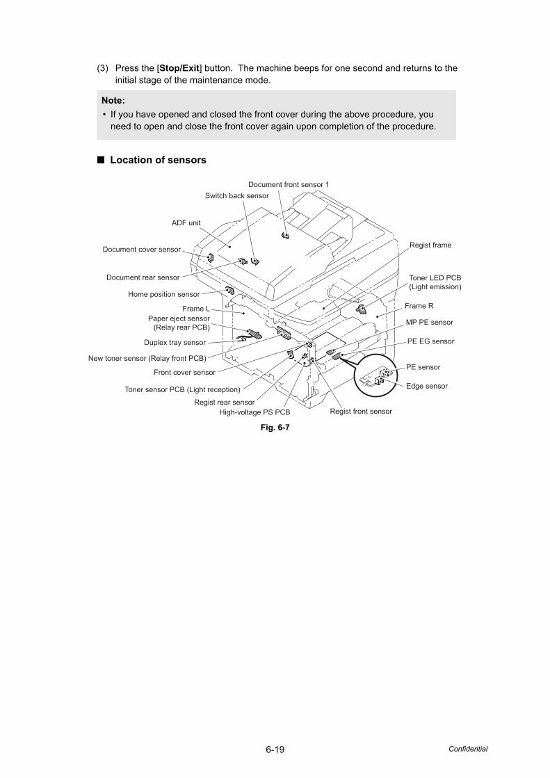
6-19 Confidential
(3) Press the [Stop/Exit] button. The machine beeps for one second and returns to the initial stage of the maintenance mode.
■ Location of sensors
Fig. 6-7
Note:• If you have opened and closed the front cover during the above procedure, you
need to open and close the front cover again upon completion of the procedure.
Document front sensor 1
Regist front sensor
Edge sensor
PE sensor
PE EG sensor
MP PE sensor
Frame R
Toner LED PCB(Light emission)
Regist frame
Switch back sensor
ADF unit
Document cover sensor
Document rear sensor
Home position sensor
Frame LPaper eject sensor
(Relay rear PCB)
Duplex tray sensor
New toner sensor (Relay front PCB)
Front cover sensor
Toner sensor PCB (Light reception)
Regist rear sensorHigh-voltage PS PCB
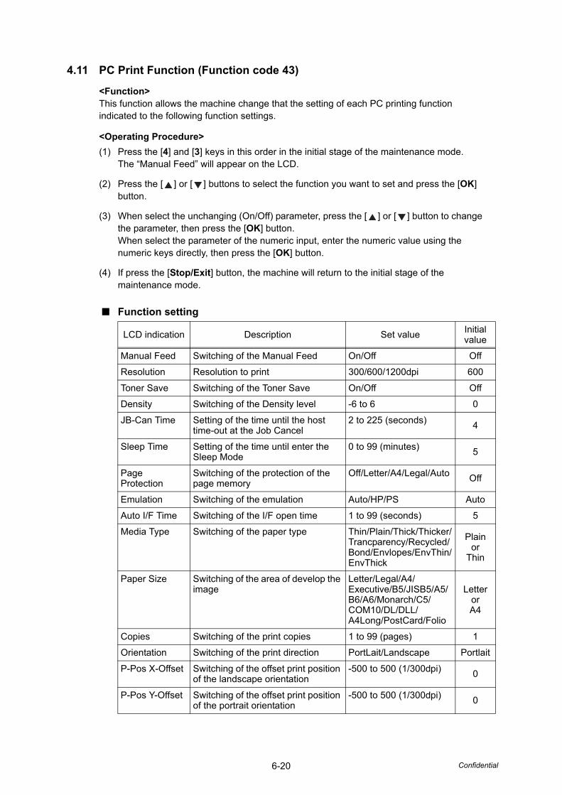
6-20 Confidential
4.11 PC Print Function (Function code 43)
<Function>This function allows the machine change that the setting of each PC printing function indicated to the following function settings.
<Operating Procedure>(1) Press the [4] and [3] keys in this order in the initial stage of the maintenance mode.
The “Manual Feed” will appear on the LCD.
(2) Press the [ ] or [ ] buttons to select the function you want to set and press the [OK] button.
(3) When select the unchanging (On/Off) parameter, press the [ ] or [ ] button to change the parameter, then press the [OK] button.When select the parameter of the numeric input, enter the numeric value using the numeric keys directly, then press the [OK] button.
(4) If press the [Stop/Exit] button, the machine will return to the initial stage of the maintenance mode.
■ Function setting
LCD indication Description Set value Initialvalue
Manual Feed Switching of the Manual Feed On/Off Off
Resolution Resolution to print 300/600/1200dpi 600
Toner Save Switching of the Toner Save On/Off Off
Density Switching of the Density level -6 to 6 0
JB-Can Time Setting of the time until the host time-out at the Job Cancel
2 to 225 (seconds) 4
Sleep Time Setting of the time until enter the Sleep Mode
0 to 99 (minutes) 5
Page Protection
Switching of the protection of the page memory
Off/Letter/A4/Legal/Auto Off
Emulation Switching of the emulation Auto/HP/PS Auto
Auto I/F Time Switching of the I/F open time 1 to 99 (seconds) 5
Media Type Switching of the paper type Thin/Plain/Thick/Thicker/Trancparency/Recycled/Bond/Envlopes/EnvThin/EnvThick
Plainor
Thin
Paper Size Switching of the area of develop the image
Letter/Legal/A4/Executive/B5/JISB5/A5/B6/A6/Monarch/C5/COM10/DL/DLL/A4Long/PostCard/Folio
LetterorA4
Copies Switching of the print copies 1 to 99 (pages) 1
Orientation Switching of the print direction PortLait/Landscape Portlait
P-Pos X-Offset Switching of the offset print position of the landscape orientation
-500 to 500 (1/300dpi) 0
P-Pos Y-Offset Switching of the offset print position of the portrait orientation
-500 to 500 (1/300dpi) 0
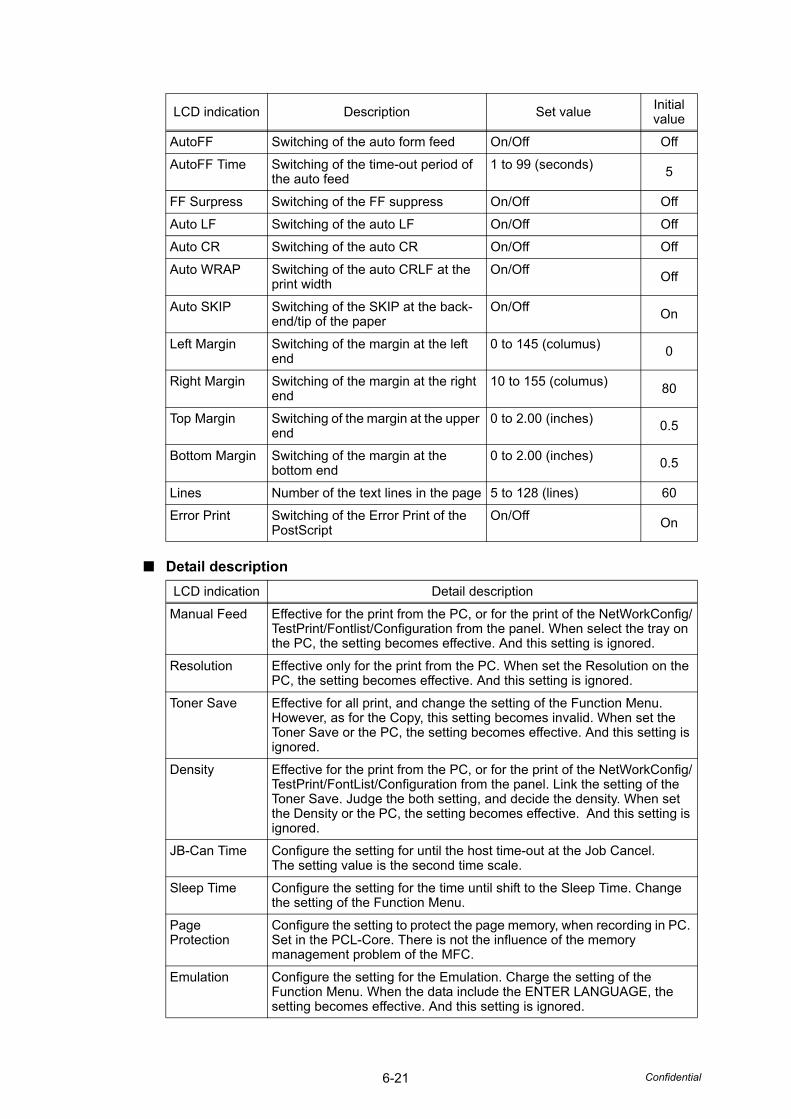
6-21 Confidential
■ Detail description
AutoFF Switching of the auto form feed On/Off Off
AutoFF Time Switching of the time-out period of the auto feed
1 to 99 (seconds) 5
FF Surpress Switching of the FF suppress On/Off Off
Auto LF Switching of the auto LF On/Off Off
Auto CR Switching of the auto CR On/Off Off
Auto WRAP Switching of the auto CRLF at the print width
On/Off Off
Auto SKIP Switching of the SKIP at the back-end/tip of the paper
On/Off On
Left Margin Switching of the margin at the left end
0 to 145 (columus) 0
Right Margin Switching of the margin at the right end
10 to 155 (columus) 80
Top Margin Switching of the margin at the upper end
0 to 2.00 (inches) 0.5
Bottom Margin Switching of the margin at the bottom end
0 to 2.00 (inches) 0.5
Lines Number of the text lines in the page 5 to 128 (lines) 60
Error Print Switching of the Error Print of the PostScript
On/Off On
LCD indication Detail description
Manual Feed Effective for the print from the PC, or for the print of the NetWorkConfig/TestPrint/Fontlist/Configuration from the panel. When select the tray on the PC, the setting becomes effective. And this setting is ignored.
Resolution Effective only for the print from the PC. When set the Resolution on the PC, the setting becomes effective. And this setting is ignored.
Toner Save Effective for all print, and change the setting of the Function Menu. However, as for the Copy, this setting becomes invalid. When set the Toner Save or the PC, the setting becomes effective. And this setting is ignored.
Density Effective for the print from the PC, or for the print of the NetWorkConfig/TestPrint/FontList/Configuration from the panel. Link the setting of the Toner Save. Judge the both setting, and decide the density. When set the Density or the PC, the setting becomes effective. And this setting is ignored.
JB-Can Time Configure the setting for until the host time-out at the Job Cancel.The setting value is the second time scale.
Sleep Time Configure the setting for the time until shift to the Sleep Time. Change the setting of the Function Menu.
Page Protection
Configure the setting to protect the page memory, when recording in PC. Set in the PCL-Core. There is not the influence of the memory management problem of the MFC.
Emulation Configure the setting for the Emulation. Charge the setting of the Function Menu. When the data include the ENTER LANGUAGE, the setting becomes effective. And this setting is ignored.
LCD indication Description Set value Initialvalue

6-22 Confidential
Auto I/F Time Configure the setting for the interface open time. The function is in the PC-Print. When the PC-Scan/Remote-SetUp works on the way, the setting becomes invalid.
Media Type Effective for the print from the PC. When set the type of the paper on the PC, the setting becomes effective. And this setting is ignored. The default value is the Plain.
Paper Size Switching of the area of develop the image. Does not set the Paper Size of the Menu, set the drawing size of the PC-Print. When set the size of the paper on the PC, the setting becomes effective. And this setting is ignored. The default value is different by the country setting. US is the Letter, and others are the A4.
Copies Effective for the print from the PC. When set the number of the copies on the PC, the setting becomes effective. And this setting is ignored.
Orientation Configure the switching for the print direction. Effective for the print from the PC.
P-Pos X-Offset Configure the setting for the offset print position of the landscape orientation. Effective for the print from the PC. When set the X-Offset on the PC, the setting becomes effective. And this setting is ignored.
P-Pos Y-Offset Configure the setting for the offset print position of the portrait orientation. Effective for the print from the PC. When set the Y-Offset on the PC, the setting becomes effective. And this setting is ignored.
AutoFF Configure the setting for the ON/OFF of the Auto Form Feed. Effective for the print from the PC.
AutoFF Time Configure the setting for the Time Out, when the Auto Form Feed is ON.
FF Surpress Configure the setting for the skip of the blank page. Effective for the print from the PC. The blank data in the Copy/Fax cannot be turned ON/OFF in this setting.
Auto LF Configure the setting for the auto line feed.
Auto CR Configure the setting for the auto Carriage Return.
Auto WRAP Configure the setting for the auto CRLF at the print width.
Auto SKIP Configure the setting for the skip at the back-end/tip of the paper and add the blank space.
Left Margin Configure the setting for the column space at the left end.
Right Margin Configure the setting for the column space at the right end.
Top Margin Configure the setting for the space at the upper end.
Bottom Margin Configure the setting for the space at the bottom end.
Lines Configure the setting for the number of the lines in the PCL.
Error Print Configure the setting for the Error Print of the BR-Script 3.
LCD indication Detail description
6-23 Confidential
4.12 Switching the USB Setting (Function code 45)
<Function>If a Vista supported PC connect with a USB device by USB full-speed 2.0, the PC's operation system may be unable to recognize the serial number of the USB device depending on the PC and the USB device. In that case, the virtual printing port for USB will increase continually whenever the PC connects to the USB device. This function can solve the problem by switching the return value of serial number to "0".
• USBNo.=ON: Return to the serial number of the machine.
• USBNo.=OFF: Return to the "0".
<Operating Procedure>(1) Press the [4] and [5] keys in this order in the initial stage of the maintenance mode.
The “USBNo.=ON” will appear on the LCD.
(2) Press the [OK] button. and select the “USBNo. = ON” or “USBNo. = OFF” by pressing the [ ] or [ ] button. And press the [OK] or [Start] button. The machine beeps for approx. one second, and return to the initial stage of the maintenance mode.
6-24 Confidential
4.13 EEPROM Customizing (User-accessible) (Function code 52)
<Function>This function allows users to customize the EEPROM settings such as language, function settings or worker switch settings.
<Operating Procedure>(1) Press the [Menu], [Start] and [Menu] buttons in this order in the ready state.
The “0” will appear on the LCD.
(2) Press the [5] and [2] keys in this order.The “Set Country” will appear on the LCD, and the country name will appear on the LCD.
(3) Press the [ ] or [ ] button to display the country name where the machine is used. Press the [OK] button while the country name is being indicated.
(4) The “1.Yes, 2.No” will appear on the LCD. Press the [1] key when it is good in the displayed country.The EEPROM is customized, and the machine returns to the ready state.Press the [2] key when it is mistake in the displayed country. Return to the procedure (3) and enter the country again.
Note:• This function is applicable Europe model only.
6-25 Confidential
4.14 Received Data Transfer Function (Function code 53)
<Function>This function transfers received FAX data to another machine. It is useful when the machine cannot print received data due to the printing mechanism being defective.
<Operating Procedure>(1) Press the [5] and [3] keys in this order in the initial stage of the maintenance mode.
The “FAX TRANSFER” appears on the LCD.
(2) To check the number of received files, press the [1] key.The “1.NO. OF JOBS” appears on the LCD. Press the [OK] button, and the number of received files appears, just as “NO. OF. JOBS: 10.”
(3) To transfer the activity report only, press the [2] key.The “2.ACTIVITY” appears.To transfer received files (together with the activity report), press the [3] key.The “3.DOCUMENTS” appears. Note that if there is no received file, the “NO DOCUMENTS” appears.
(4) To transfer the communication list for the latest communication, press the [4] key.The “4.COM.LIST (NEW)” appears.To transfer the communication list for last three errors, press the [5] key.The “5.COM.LIST (ERR3)” appears.
(5) With the “2.ACTIVITY,” “3.DOCUMENTS,” “4.COM.LIST (NEW),” or “5.COM.LIST(ERR3)” being displayed, press the [OK] button.The “ENTER NO. & SET” appears.
(6) Enter the telephone number of the receiver machine and press the [OK] button again.
Note:• The number of files that can be transferred at a time is 99. To transfer 100 files or
more, carry out the following procedure more than one time.
Note:• Be sure to type the telephone number with the numerical buttons. No one-touch
dialing is allowed in this procedure. The machine displays the “ACCEPTED” for approx. two seconds and starts dialing to transfer data.No station ID will be attached. A cover page and end page as shown on the next page will be automatically attached, instead.
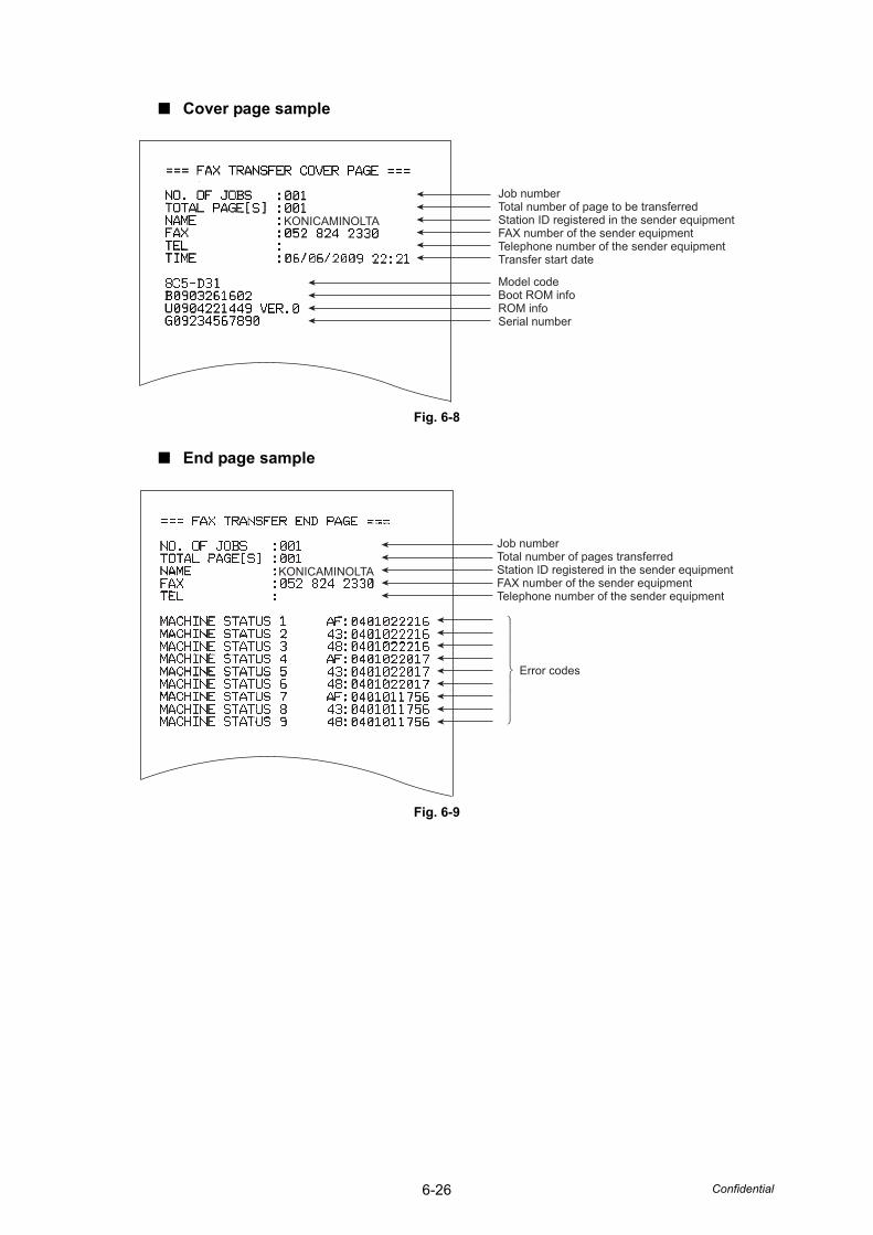
6-26 Confidential
■ Cover page sample
Fig. 6-8
■ End page sample
Fig. 6-9
KONICAMINOLTA
Model codeBoot ROM infoROM infoSerial number
Job numberTotal number of page to be transferredStation ID registered in the sender equipmentFAX number of the sender equipmentTelephone number of the sender equipmentTransfer start date
Error codes
Job numberTotal number of pages transferredStation ID registered in the sender equipmentFAX number of the sender equipmentTelephone number of the sender equipment
KONICAMINOLTA
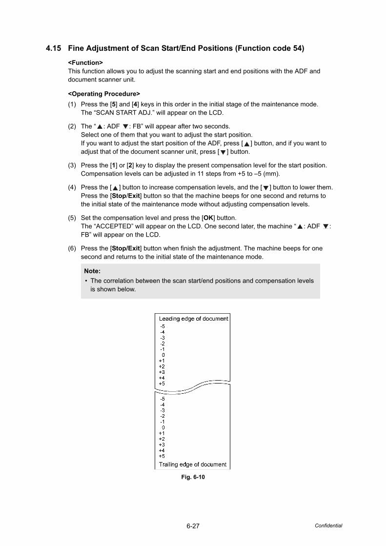
6-27 Confidential
4.15 Fine Adjustment of Scan Start/End Positions (Function code 54)
<Function>This function allows you to adjust the scanning start and end positions with the ADF and document scanner unit.
<Operating Procedure>(1) Press the [5] and [4] keys in this order in the initial stage of the maintenance mode.
The “SCAN START ADJ.” will appear on the LCD.
(2) The “ : ADF : FB” will appear after two seconds.Select one of them that you want to adjust the start position.If you want to adjust the start position of the ADF, press [ ] button, and if you want to adjust that of the document scanner unit, press [ ] button.
(3) Press the [1] or [2] key to display the present compensation level for the start position.Compensation levels can be adjusted in 11 steps from +5 to –5 (mm).
(4) Press the [ ] button to increase compensation levels, and the [ ] button to lower them.Press the [Stop/Exit] button so that the machine beeps for one second and returns to the initial state of the maintenance mode without adjusting compensation levels.
(5) Set the compensation level and press the [OK] button.The “ACCEPTED” will appear on the LCD. One second later, the machine “ : ADF : FB” will appear on the LCD.
(6) Press the [Stop/Exit] button when finish the adjustment. The machine beeps for one second and returns to the initial state of the maintenance mode.
Fig. 6-10
Note:• The correlation between the scan start/end positions and compensation levels
is shown below.
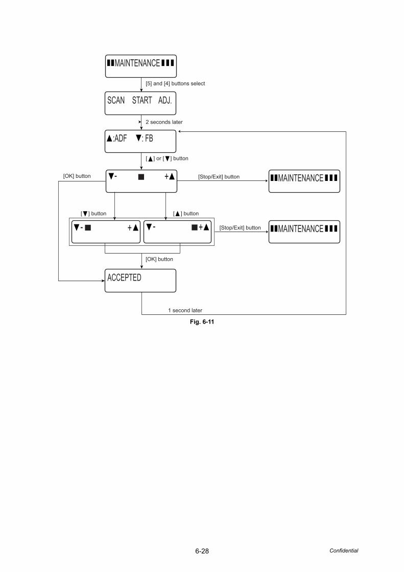
6-28 Confidential
Fig. 6-11
MAINTENANCE
ACCEPTED
:ADF : FB
SCAN START ADJ.
+-
+- +-
MAINTENANCE
MAINTENANCE
[5] and [4] buttons select
[Stop/Exit] button
[Stop/Exit] button
[ ] or [ ] button
[OK] button
[OK] button
1 second later
2 seconds later
[ ] button [ ] button
6-29 Confidential
4.16 Acquisition of White Level Data and CCD Scanner Area Setting(Function code 55)
<Function>This function allows the machine to obtain white level data for the scanner module and save it together with the scanner module area into the EEPROM on the main PCB.
<Operating Procedure>(1) Press the [5] key twice in the initial stage of the maintenance mode.
"PRESS START" will appear on the LCD.
(2) Press [START] button, then "SCANNER AREA START" will appear on the LCD.
(3) When setting of the scanner area is completed, a 4-digit number will appear on the LCD.(e.g., 4723)
* If you press the [Stop/Exit] button at this point, the machine will beep for one second and return to the initial stage of the maintenance mode.
Enter the input data value of a 5-digit number based on the 4-digit number to be displayed referring to the table below. (e.g., 4723 → 47247)
(4) The machine saves the magnification compensation setting value into the EEPROM, and then it beeps for one second and returns to the initial stage of the maintenance mode.
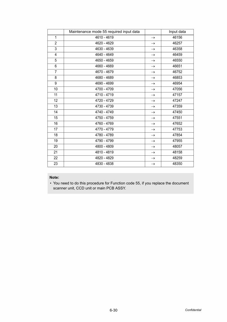
6-30 Confidential
Maintenance mode 55 required input data Input data1 4610 - 4619 → 461562 4620 - 4629 → 462573 4630 - 4639 → 463584 4640 - 4649 → 464595 4650 - 4659 → 465506 4660 - 4669 → 466517 4670 - 4679 → 467528 4680 - 4689 → 468539 4690 - 4699 → 46954
10 4700 - 4709 → 4705611 4710 - 4719 → 4715712 4720 - 4729 → 4724713 4730 - 4739 → 4735914 4740 - 4749 → 4745015 4750 - 4759 → 4755116 4760 - 4769 → 4765217 4770 - 4779 → 4775318 4780 - 4789 → 4785419 4790 - 4799 → 4795520 4800 - 4809 → 4805721 4810 - 4819 → 4815822 4820 - 4829 → 4825923 4830 - 4838 → 48350
Note:• You need to do this procedure for Function code 55, if you replace the document
scanner unit, CCD unit or main PCB ASSY.
6-31 Confidential
4.17 Paper Feeding and Ejecting Test (Function code 67)
<Function>This function allows you to check that a sheet of paper is fed and ejected correctly by printing the grid pattern on a page, whose interval is 1cm.
<Operating Procedure>(1) Press the [6] and [7] keys in this order in the initial stage of the maintenance mode.
(2) The “SELECT A4” will appear on the LCD. Select the paper size by using [ ] [ ] button. Press the [OK] button.
(3) The “SELECT: TRAY1” will appear on the LCD. Select the paper tray by using [ ] [ ] button. Press the [OK] button.
(4) The “PAPER DEED TEST” will appear on the LCD. The test printing is started, and the grid pattern is printed.
(5) Press the [Stop/Exit] button so that machine stops printing. Then the machine returns to the initial stage of the maintenance mode.
4.18 EEPROM Customizing (Function code 74)
<Function>This function allows you to customize the EEPROM according to language, function settings, and worker switch settings.
<Operating Procedure>(1) Press the [7] and [4] keys in this order in the initial stage of the maintenance mode.
The current customizing code appears.
(2) Enter the desired customizing code 4 digit numbers listed on next page (e.g., bizhub 20 (UK): 0304). The newly entered code appears.
(3) Press the [Start] button.The machine saves the setting and displays the “PARAMETER INIT” on the LCD. The machine beeps for one second and returns to the initial stage of the maintenance mode.
If you press the [Stop/Exit] button or no buttons are pressed for one minute in the above procedure, the machine stops the procedure, beeps for one second and returns to the initial stage of the maintenance mode.The modification of the setting data is not saved in this case.
Note:• In the case that the front cover is opened, or that there is no paper in the tray during
test printing, the test printing is stopped.
Note:• If you replace the main PCB, be sure to carry out this procedure.
Note:• The machine does not work properly when an incorrect code is entered.
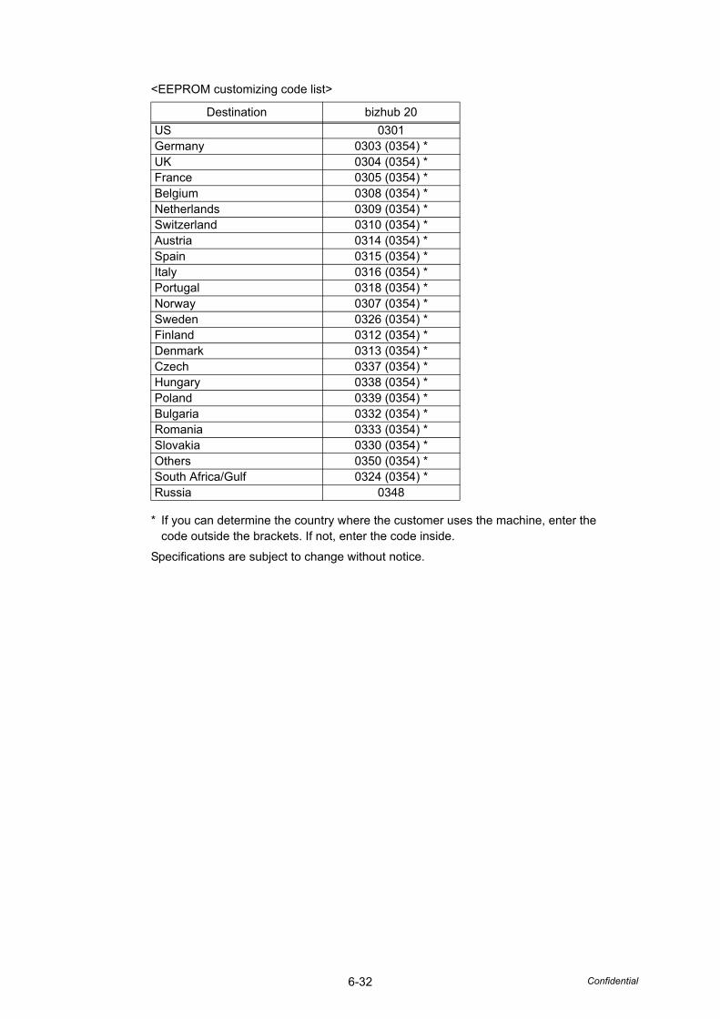
6-32 Confidential
<EEPROM customizing code list>
* If you can determine the country where the customer uses the machine, enter the code outside the brackets. If not, enter the code inside.
Specifications are subject to change without notice.
Destination bizhub 20US 0301Germany 0303 (0354) *UK 0304 (0354) *France 0305 (0354) *Belgium 0308 (0354) *Netherlands 0309 (0354) *Switzerland 0310 (0354) *Austria 0314 (0354) *Spain 0315 (0354) *Italy 0316 (0354) *Portugal 0318 (0354) *Norway 0307 (0354) *Sweden 0326 (0354) *Finland 0312 (0354) *Denmark 0313 (0354) *Czech 0337 (0354) *Hungary 0338 (0354) *Poland 0339 (0354) *Bulgaria 0332 (0354) *Romania 0333 (0354) *Slovakia 0330 (0354) *Others 0350 (0354) *South Africa/Gulf 0324 (0354) *Russia 0348
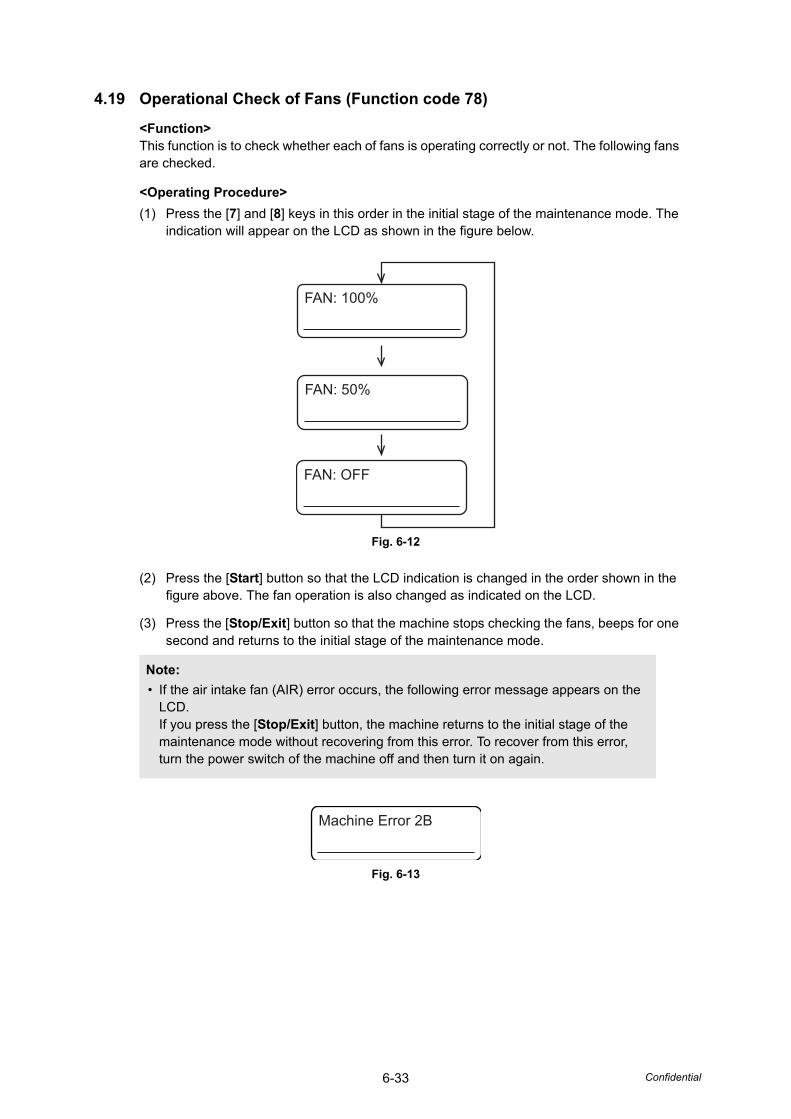
6-33 Confidential
4.19 Operational Check of Fans (Function code 78)
<Function>This function is to check whether each of fans is operating correctly or not. The following fans are checked.
<Operating Procedure>(1) Press the [7] and [8] keys in this order in the initial stage of the maintenance mode. The
indication will appear on the LCD as shown in the figure below.
Fig. 6-12
(2) Press the [Start] button so that the LCD indication is changed in the order shown in the figure above. The fan operation is also changed as indicated on the LCD.
(3) Press the [Stop/Exit] button so that the machine stops checking the fans, beeps for one second and returns to the initial stage of the maintenance mode.
Fig. 6-13
Note:• If the air intake fan (AIR) error occurs, the following error message appears on the
LCD.If you press the [Stop/Exit] button, the machine returns to the initial stage of the maintenance mode without recovering from this error. To recover from this error, turn the power switch of the machine off and then turn it on again.
FAN: 100%
FAN: 50%
FAN: OFF
Machine Error 2B
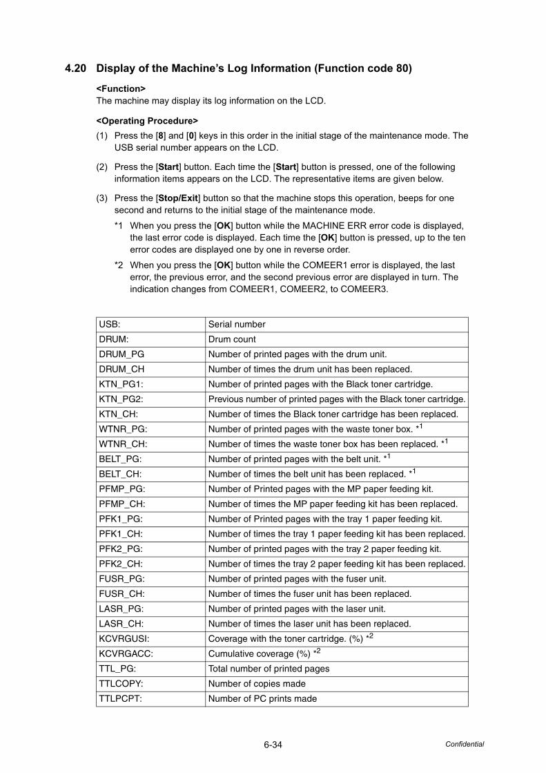
6-34 Confidential
4.20 Display of the Machine’s Log Information (Function code 80)
<Function>The machine may display its log information on the LCD.
<Operating Procedure>(1) Press the [8] and [0] keys in this order in the initial stage of the maintenance mode. The
USB serial number appears on the LCD.
(2) Press the [Start] button. Each time the [Start] button is pressed, one of the following information items appears on the LCD. The representative items are given below.
(3) Press the [Stop/Exit] button so that the machine stops this operation, beeps for one second and returns to the initial stage of the maintenance mode.
*1 When you press the [OK] button while the MACHINE ERR error code is displayed, the last error code is displayed. Each time the [OK] button is pressed, up to the ten error codes are displayed one by one in reverse order.
*2 When you press the [OK] button while the COMEER1 error is displayed, the last error, the previous error, and the second previous error are displayed in turn. The indication changes from COMEER1, COMEER2, to COMEER3.
USB: Serial number
DRUM: Drum count
DRUM_PG Number of printed pages with the drum unit.
DRUM_CH Number of times the drum unit has been replaced.
KTN_PG1: Number of printed pages with the Black toner cartridge.
KTN_PG2: Previous number of printed pages with the Black toner cartridge.
KTN_CH: Number of times the Black toner cartridge has been replaced.
WTNR_PG: Number of printed pages with the waste toner box. *1
WTNR_CH: Number of times the waste toner box has been replaced. *1
BELT_PG: Number of printed pages with the belt unit. *1
BELT_CH: Number of times the belt unit has been replaced. *1
PFMP_PG: Number of Printed pages with the MP paper feeding kit.
PFMP_CH: Number of times the MP paper feeding kit has been replaced.
PFK1_PG: Number of Printed pages with the tray 1 paper feeding kit.
PFK1_CH: Number of times the tray 1 paper feeding kit has been replaced.
PFK2_PG: Number of printed pages with the tray 2 paper feeding kit.
PFK2_CH: Number of times the tray 2 paper feeding kit has been replaced.
FUSR_PG: Number of printed pages with the fuser unit.
FUSR_CH: Number of times the fuser unit has been replaced.
LASR_PG: Number of printed pages with the laser unit.
LASR_CH: Number of times the laser unit has been replaced.
KCVRGUSI: Coverage with the toner cartridge. (%) *2
KCVRGACC: Cumulative coverage (%) *2
TTL_PG: Total number of printed pages
TTLCOPY: Number of copies made
TTLPCPT: Number of PC prints made
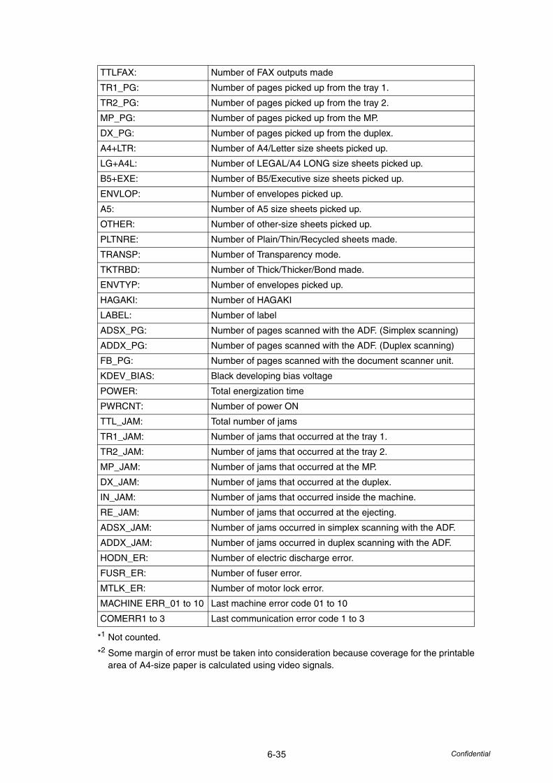
6-35 Confidential
*1 Not counted.
*2 Some margin of error must be taken into consideration because coverage for the printable area of A4-size paper is calculated using video signals.
TTLFAX: Number of FAX outputs made
TR1_PG: Number of pages picked up from the tray 1.
TR2_PG: Number of pages picked up from the tray 2.
MP_PG: Number of pages picked up from the MP.
DX_PG: Number of pages picked up from the duplex.
A4+LTR: Number of A4/Letter size sheets picked up.
LG+A4L: Number of LEGAL/A4 LONG size sheets picked up.
B5+EXE: Number of B5/Executive size sheets picked up.
ENVLOP: Number of envelopes picked up.
A5: Number of A5 size sheets picked up.
OTHER: Number of other-size sheets picked up.
PLTNRE: Number of Plain/Thin/Recycled sheets made.
TRANSP: Number of Transparency mode.
TKTRBD: Number of Thick/Thicker/Bond made.
ENVTYP: Number of envelopes picked up.
HAGAKI: Number of HAGAKI
LABEL: Number of label
ADSX_PG: Number of pages scanned with the ADF. (Simplex scanning)
ADDX_PG: Number of pages scanned with the ADF. (Duplex scanning)
FB_PG: Number of pages scanned with the document scanner unit.
KDEV_BIAS: Black developing bias voltage
POWER: Total energization time
PWRCNT: Number of power ON
TTL_JAM: Total number of jams
TR1_JAM: Number of jams that occurred at the tray 1.
TR2_JAM: Number of jams that occurred at the tray 2.
MP_JAM: Number of jams that occurred at the MP.
DX_JAM: Number of jams that occurred at the duplex.
IN_JAM: Number of jams that occurred inside the machine.
RE_JAM: Number of jams that occurred at the ejecting.
ADSX_JAM: Number of jams occurred in simplex scanning with the ADF.
ADDX_JAM: Number of jams occurred in duplex scanning with the ADF.
HODN_ER: Number of electric discharge error.
FUSR_ER: Number of fuser error.
MTLK_ER: Number of motor lock error.
MACHINE ERR_01 to 10 Last machine error code 01 to 10
COMERR1 to 3 Last communication error code 1 to 3
6-36 Confidential
4.21 Error Code Indication (Function code 82)
<Function>This function displays an error code of the machine on the LCD.
<Operating Procedure>(1) Press the [8] and [2] keys in this order in the initial stage of the maintenance mode.
The machine displays “MACHINE ERROR X X” on the LCD.
(2) Press the [Stop/Exit] button. The machine beeps for one second and returns to the initial stage of the maintenance mode.
4.22 Output of Transmission Log to the Telephone Line (Function code 87)
<Function>This function outputs the transmission log (that the machine has stored about the latest transmission) to the telephone line. It allows the service personnel to receive the transmission log of the user's machine at a remote location and use it for analyzing problems arising in the user's machine.
<Operating Procedure>(1) If the user's machine has a transmission-related problem, call the user's machine at a
remote location from your machine.
(2) If the line is connected, have the user perform the following:
1) Hook up to the external phone.
2) Press the [Menu], [Start], [Menu] buttons in this order.
3) Press the [8] and [7] keys.The above operation makes the user's machine send CNG to your machine for sending the transmission log.
(3) If you hear the CNG sent from the user's machine, press the [Start] button of your machine.Your machine will start to receive the transmission log from the user's machine.
6-37 Confidential
4.23 Counter Reset After Replacing the Fuser Unit,Laser Unit and Paper Feed Kit (Function code 88)
<Function>The number of replacement is increased by one, and the warning indication “Replace ***” is cleared, with implementing this operation after replacing the fuser unit, laser unit and paper feed Kit (MP, T1, T2).
<Operating Procedure>(1) Press the [8] and [8] keys in this order in the initial stage of the maintenance mode.
(2) The LCD shows the “Reset Laser Unit”.
(3) Press the [ ] or [ ] button to select the item you want to reset. The LCD shows.“Reset-Laser Unit”“Reset PF-KIT T2”“Reset PF-KIT T1”“Reset PF-KIT MP”“Reset-Fuser Unit”
(4) Press the [OK] or [Start] button, then “ *** OK?” will appear on the LCD.
(5) OK: Press the [Start] button to reset the counter of the selected part and returns the operating procedure (2) mode.
NG: Press the [ ] button to return the operating procedure (2) mode. Then select again the part which you want to reset by using [ ] button or [ ] button.
4.24 Maintenance Mode Finish (Function code 99)
<Function>Finish the maintenance mode.
<Operating Procedure>(1) Press the [9] key twice in the initial stage of the maintenance mode.
(2) The maintenance mode is finished, and the machine returns to the standby status.
6-38 Confidential
5. OTHER SERVICE FUNCTIONS
5.1 Resetting the Periodical Maintenance Parts Life
■ Resetting the Life Counter of the Fuser Unit
<Function>This function allows you to reset the page counter of the fuser unit and increase the number of replacement times by one.
<Operating Procedure>
(1) Press the [3] and [9] keys at the same time in the ready state.The “Reset Menu” will appear on the LCD.
(2) Press the [ ] button a few times to select “Fuser”.
(3) Press the [OK] button. The “1. Reset / 2. Exit” will appear on the LCD.
(4) Press the [1] key when resetting the life counter of the fuser unit. Press the [2] key if not resetting.
(5) The “Accepted” will appear on the LCD if pressing the [1] key. The page counter of the fuser unit is reset, and the number of replacement times is increased by one. Then, the machine returns to the ready state. If pressing the [2] key, the machine do not reset the page counter and the “Fuser” will appear on the LCD.
■ Resetting the Life Counter of the Drum Unit
<Function>This function allows you to reset the page counter of the drum unit and increase the number of replacement times by one.
<Operating Procedure>
(1) Press the [3] and [9] keys at the same time in the ready state.The “Reset Menu” will appear on the LCD.
(2) Press the [ ] button a few times to select “Drum”.
(3) Press the [OK] button. The “1. Reset / 2. Exit” will appear on the LCD.
(4) Press the [1] key when resetting the life counter of the drum unit. Press the [2] key if not resetting.
(5) The “Accepted” will appear on the LCD if pressing the [1] key. The page counter of the drum unit is reset, and the number of replacement times is increased by one. Then, the machine returns to the ready state. If pressing the [2] key, the machine do not reset the page counter and the “Drum” will appear on the LCD.
6-39 Confidential
■ Resetting the Life Counter of the Paper Feeding Kit
<Function>This function allows you to reset the page counter of the paper feeding kit (1 or 2) and increase the number of replacement times by one.
<Operating Procedure>
(1) Press the [3] and [9] keys at the same time in the ready state.The “Reset Menu” will appear on the LCD.
(2) Press the [ ] button a few times to select “PF Kit 1” or “PF Kit 2”.
(3) Press the [OK] button. The “1. Reset / 2. Exit” will appear on the LCD.
(4) Press the [1] key when resetting the life counter of the paper feeding kit. Press the [2] key if not resetting.
(5) The “Accepted” will appear on the LCD if pressing the [1] key. The page counter of the paper feeding kit is reset, and the number of replacement times is increased by one. Then, the machine returns to the ready state. If pressing the [2] key, the machine do not reset the page counter and the “PF Kit 1” or “PF Kit 2” will appear on the LCD.
■ Resetting the Life Counter of the MP Paper Feeding Kit
<Function>This function allows you to reset the page counter of the MP paper feeding kit and increase the number of replacement times by one.
<Operating Procedure>
(1) Press the [3] and [9] keys at the same time in the ready state.The “Reset Menu” will appear on the LCD.
(2) Press the [ ] button a few times to select “PF Kit MP”.
(3) Press the [OK] button. The “1. Reset / 2. Exit” will appear on the LCD.
(4) Press the [1] key when resetting the life counter of the MP paper feeding kit. Press the [2] key if not resetting.
(5) The “Accepted” will appear on the LCD if pressing the [1] key. The page counter of the MP paper feeding kit is reset, and the number of replacement times is increased by one. Then, the machine returns to the ready state. If pressing the [2] key, the machine do not reset the page counter and the “PF Kit MP” will appear on the LCD.
6-40 Confidential
■ Resetting the Life Counter of the Laser Unit
<Function>This function allows you to reset the page counter of the laser unit and increase the number of replacement times by one.
<Operating Procedure>
(1) Press the [3] and [9] keys at the same time in the ready state.The “Reset Menu” will appear on the LCD.
(2) Press the [ ] button a few times to select “Laser”.
(3) Press the [OK] button. The “1. Reset / 2. Exit” will appear on the LCD.
(4) Press the [1] key when resetting the life counter of the laser unit. Press the [2] key if not resetting.
(5) The “Accepted” will appear on the LCD if pressing the [1] key. The page counter of the laser unit is reset, and the number of replacement times is increased by one. Then, the machine returns to the ready state. If pressing the [2] key, the machine do not reset the page counter and the “Laser” will appear on the LCD.
5.2 Develop Roller / Developing Bias Voltage Counter Reset Function Since print density is likely to become darker as the toner gets older, the developing bias is lowered by degrees (bias voltage is reduced) according to the number of develop roller rotations so that an almost fixed density can be maintained from the beginning to the end. The developing bias voltage can be verified in the display of log information (Function code 80).
In the case that the toner cartridge is replaced with a new one, the develop roller counter and developing bias voltage are reset at the same time. This function allows you to reset these manually.
<Operating Procedure>
(1) Press the [Clear/Back] button while the front cover is being opened.
(2) The “Replace Drum ?” “1. Yes 2. No” will appear on the LCD. If resetting the counter, press the [1] key. If not, press the [2] key.
(3) Press the [*], [0] and [0] key in this order, the counter will reset and "Accepted" will appear on the LCD.
(4) The machine returns to the status that the front cover is opened.
Panel Operation Function
Pressing the [Clear/Back] button while the front cover is being opened.
Menus of the develop roller counter reset
Note:• If there is no operation for 60 seconds or more, the machine automatically
deactives the develop roller / developing bias voltage counter reset function. The “Cover is Open Close the Front Cover” will appear on the LCD. Then, the machine returns to the ready state.

6-41 Confidential
5.3 Drum condensation countermeasure modeThe printing spots may occur with the condensation of the surface of the drum in the high humidity environment. When the drum condensation countermeasure mode is set to ON to follow the procedure described below, you can remedy the condensation of the surface of the drum in drying by heat of the fuser unit.
<Operating Procedure>
(1) Open the front cover.
(2) Press the [Enlarge/Reduce] button. The LCD shows the “LONG WARMUP MODE 1. On 2. Off ”
(3) Select the “ON” or “OFF” by pressing the [1] or [2] button, and press the [OK] button.The LCD shows the “Accepted”, and the machine returns to the standby status.
5.4 Unlocking and Clearing the Password of the Function Lock / Setting Lock
■ How to clear the passwordThe user's can not clear the password that registered by operation of the panel. Perform the following procedures to clear the registered password.
<Operating Procedure>
(1) Press the [Menu], [#], [2], [7], [9], [0] and [0] button in this order in the ready state.The “0” will appear on the LCD.
(2) The registered password is cleared, and the machine returns to the ready state.
5.5 Clearing the Data of the Secure PrintIf forgot the password of the Secure Print, turn the power switch off and then turn it on again to clear the printing data.

Confidential
CHAPTER 7CIRCUIT DIAGRAMS, WIRING DIAGRAM

Confidential
CHAPTER 7 CIRCUIT DIAGRAMS, WIRING DIAGRAM
This chapter provides the circuit diagrams of the High-voltage power supply PCB, LVPS PCB and NCU PCB and the wiring diagrams that help you understand the connections between PCBs.
CONTENTS1. CIRCUIT DIAGRAMS....................................................................................................7-1
2. WIRING DIAGRAM .......................................................................................................7-7
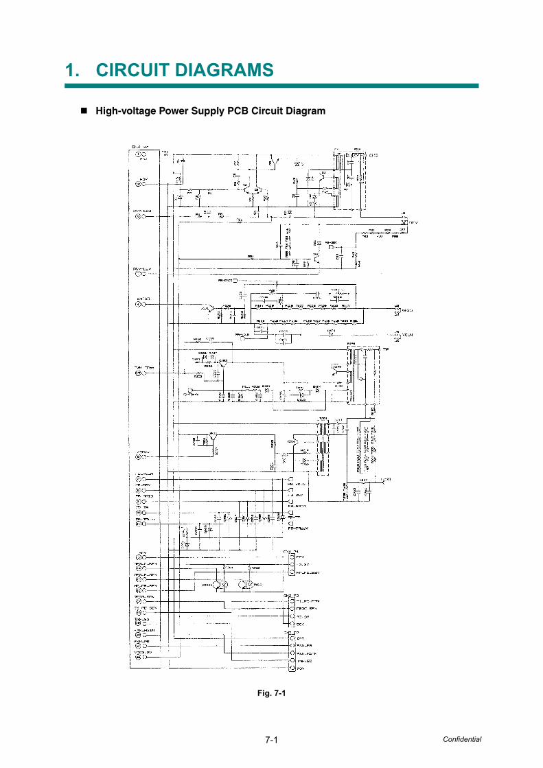
7-1 Confidential
1. CIRCUIT DIAGRAMS
High-voltage Power Supply PCB Circuit Diagram
Fig. 7-1
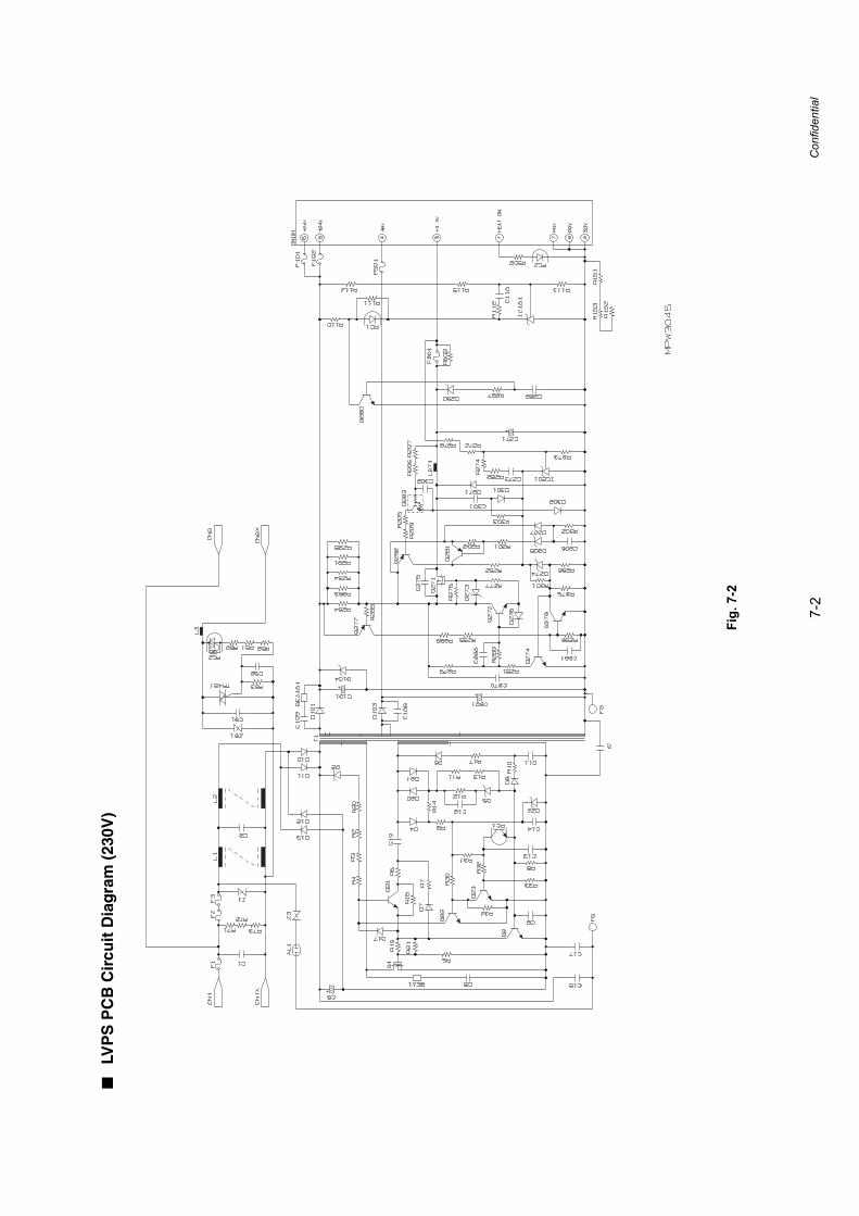
7-2
Confidential
■LV
PS
PC
B C
ircu
it D
iag
ram
(23
0V)
Fig.
7-2
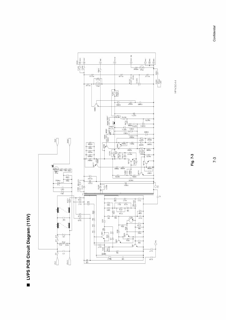
7-3
Confidential
■LV
PS
PC
B C
ircu
it D
iag
ram
(11
5V)
Fig.
7-3
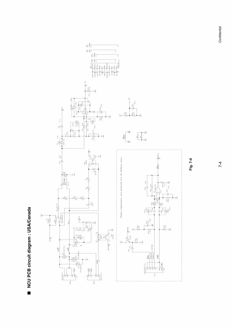
7-4
Confidential
■N
CU
PC
B c
ircu
it d
iag
ram
: U
SA
/Can
ada
Fig.
7-4
+
+-
+
+
+-
R27
4.7k
C16
C470
6.3V
+5V
REF
C4
C103
GND
U1
BA10358
6 57
GND
6B
TELSL
@C17
C104
@R21
24k
@C14
C471
@R15
150k
REF
R23
3.3k
GND
@C15 C104
C7
C104
C5
C2.2
50V
@C9
C221
@C10
C471
@R8
510
@R19
2.7k
@R17
150k
GND
R16
100k
6B
RL1
@R13
3.3k
R25
620
REF
GND
R18
620
@C18C221
GND
@R24
2.7k
@C6C10
+5V
C8
C104
R28
100k
R14
100k
R10
2.7k
C19
C222
U1
BA10358
4
2 31
8
@C12C101
GND
@R9
150
REF
R12
100k
@R22
24k
D7
1SS120
PH2
TLP320
AK1
AK2 E
C
@C3
C10
35V
@PH1
PS2533-1
A K
EC
D3
1SS120
R7
100
2W
GND
D5
RA-242M-C6
R6
6.2k
@D1
ERA15-04
D4
RA-351M-V6-2
@D2S1ZB60
A1
-A2
+
@R11202W
R2 24k
FG
6BCI
GND
+24V
R5
6.2k
C1 C474
250V
PH3
TLP421
A
K
EC
@T1
BT-17
GND
R4
6.2k
6BSL
R11
4.3k
5A
SL
GND
2C
TELRL
2A
CML
2B
PLS5B
RL1
+24V3D
TELSL
2C
TELOFF
4B
CI
+5V
@J3
285D-D440J-111
1XX
2XX
3XX
4XX
5GND
6GND
+5V
@Q1
C5395
C
B
E
6B
TELOFF
6B
CML
GND
6BTELRL @R20
100
@C13 C470
10V
GND
+5V
GND
FG
6CPLS
J2
R41-4910-A
3XX
4XX
7FG
8FG J1
R41-4910-A
3XX
4XX
7FG
8FG
NC
NC
NC
NC
C11
C101
L8
L1
L3
L2
@L4
@L7
@L6
@L5
C2
C102
P1
B11B-PH-K-S
1PLS
2RL1
3SL
4+5V
5TELOFF
6GND
7CI
8CML
9+24V
10TELSL
11TELRL
NC
SW1
A5X-24E-908
1212
11 7
R3 24k
D6
RA-242M-C6
C102
C104
C103 C104
C104 C104
C101
C104
JW1
JW2
GND
GND
JW3
JW4
+
+
(LINE)
(EXT)
(H.S)
FB
US
CAN
FB
US
SF
CAN
SF
These components are mounted for SF Models only.
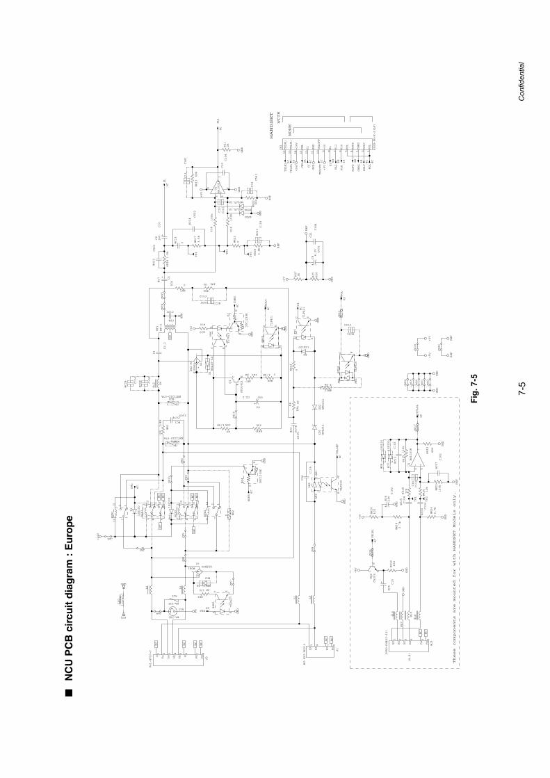
7-5
Confidential
■N
CU
PC
B c
ircu
it d
iag
ram
: E
uro
pe
Fig.
7-5
+
+-
+
+
+
+
+-
@R3
120 2W
@D3
ERA15-04
@C2
C474
250V
R6
39k
1W
PH3
TLP421
A K
EC
PH2
TLP320
CE
AK2
AK1
D1
1SS120
D6
1SS120
@PH1
TLP627
A K
EC
@R31
20k
C4
C2.2 50V
ZD2
MTZJ12
ZD1
MTZJ12
@R7
1202W
@R8
01/4W
@ZNR1ENC121D-07A
AL2
RA-242
@DB1S1ZB60
A1
-A2
+
@Q4
DTC123EK
C
B
E
PH6
TLP421
A K
EC
DB2
S1ZB60 A1
-
A2
+
D5ERA15-04
@C7 C1
50V
6CPLS
6CCI
6CTELOFF
6C
CML
FG1
GND
GND
GND
FG
GND
GND
GND
+24V
6C
RDPS
R9
10k1/4W
Q1
KTD1411
C
B
E
@CR1
9112
10
8
435
@D4
1SS120
@CR2
9112
10
8
435
C24
C102
@PH5
TLP421
A K
EC
GND
6CADLC
@C29 C153
@C28 C153
@SW2
1212
11 7@SW1
1212
11 7
@R2
0
J1
MJ-62J-RD315 3
XX
4XX
7FG
8FG
J2
R41-4910-C
1S
2Ta
3La
4Lb
5Tb
6E
7FG
8FG
@T1
BT-6
NC
NC
NC
NC
NC
NC
GND
@R17
3.9k
@R13
68k
R11
2k
@R181.5k
6CSL
R14
100k
U1
BA10358
4
2 31
8
C18
C561
R16
100k
GND
C10C104
+5V
C11
C561
@C22
C563
6C
RL1
REF
C9
C10
16V
@C14
C822
@R22
68k
4C
CI
GND
6B
RL1
3C
TELOFF
+24V
+5V
2C
TELRL
2A
CML
6B
SL3D
TELSL
1B
PLS
4B
CHRG
2B
RDPS
R25
820
C8
C470
6.3V
GND
R27
1k
+5V
REF
C13
C101
GND
@C5C10
6C
TELSL
@C12
C102
@R28
2.7k
@D7
1SS120
@C20 C104
@R21
120k
@D8
1SS120
@R15
120k
NC
@R10
150
GND
REF
@C6
C100
16V
NC
@C17
C102
GND
6CTELRL
@R29
100
GND
U1
BA10358
6 57
C16
C101
@R24
2.7k
@R20 12k
@C15
C104
@Q2
C5395
C
B
E
@J3
285D-D440J-111
1XX
2XX
3XX
4XX
5FG
6FG
@R19
12k
GND
@R12
680
+5V
+5V
+5V
R30
470
6CCHRG
GND
Q3
DTC123EK
C
B
E
4C
ADLC
C3
C2.2
L10
L4
L5
L1
@L6
@L7
@L9
@L8
REF
@R26
3.9k
@C23C103
GND
@ZD3
MTZJ5.1B @ZD4
MTZJ5.1B
C21
C104
@D2ENC121D-07A
@R4
39k1W
TP2
TP1
TP3
NC
TP4
@R23
0@C19
0
TP5
C26
C105
AL1
RA-311
@L2 JW
@C27
C332
250V
@R5
0
NC
NC
NC
NC
NC
NC
@R1
100
1/4W @C1
C474250V
@R33
0
@R32
3.9k
@PH4
TLP620
AK1
AK2
EC
GND
@C25
C104
CN1
B16B-PH-K-S(LF)
1POL
2ADLC
3CHRG
4RDPS
5POL
6PLS
7RL1
8SL
9+5V
10TELOFF
11GND
12CI
13CML
14+24V
15TELSL
16TELRL
4C
POL
6DPOL
L3
+5V
GND
JW20
JW19
GND
JW22
JW23
REF
REF
JW18
JW12
JW21
+5V
JW2
JW3
JW4
JW5
JW6
JW7
JW8
JW9
JW10
JW11
JW1
JW14
JW15
JW13
JW16
JW17
+
(H.S)
WITH
NONE
These components are mounted for with HANDSET Models only.
HANDSET
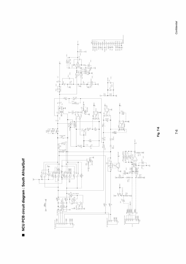
7-6
Confidential
■N
CU
PC
B c
ircu
it d
iag
ram
: S
ou
th A
fric
a/G
ulf
Fig.
7-6
+
+
+-
+
+
+
+
+-
@R3
120 2W
@D3
ERA15-04
@C2
C474
250V
R6
39k
1W
PH3
TLP421
A K
EC
PH2
TLP320(F)C
E
AK2
AK1
D1
1SS120
D6
1SS120
@PH1
TLP627(F)
A K
EC
@R31
20k
C4
C2.2 50V
ZD2
MTZJ12
ZD1
MTZJ12
@R7
1202W
@R8
JW
@ZNR1ENC121D-07A
@AL2
RA-242M-C6
@DB1S1ZB60-7101
A1
-A2
+
@Q4
DTC123EK
C
B
E
PH6
TLP421
A K
EC
DB2
S1ZB60-7101 A1
-
A2
+
D5ERA15-04
@C7 C1
50V
6CPLS
6CCI
6CTELOFF
6C
CML
FG1
GND
GND
GND
FG
GND
GND
GND
+24V
6C
RDPS
R9
10k1/4W
Q1
KTD1411/P
C
B
E
@CR1
9112
10
8
435
@D4
1SS120
@CR2
9112
10
8
435
C24
C102
@PH5
TLP421
A K
EC
GND
6CADLC
@C29 C153
@C28 C153
@SW2
1212
11 7@SW1
1212
11 7
@R2
JW
J1
MJ-62J-RD315(LF)
3XX
4XX
7FG
8FG
J2
MJ-66J-RD315(LF)
1S
2Ta
3La
4Lb
5Tb
6E
7FG
8FG
@T1
BT-6 A(EX-16)
NC
NC
NC
NC
NC
NC
GND
@R17
3.9k
@R13
68k
R11
2k
@R181.5k
6CSL
R14
100k
U1
BA10358
4
2 31
8
C18
C561
R16
100k
GND
C10
C104
+5V
C11
C561
@C22
C563
6C
RL1
REF
C9
C10
16V
@C14
C822
@R22
68k
4C
CI
GND
6B
RL1
3C
TELOFF
+24V
+5V
2C
TELRL
2A
CML
6B
SL3D
TELSL
1B
PLS
4B
CHRG
2B
RDPS
R25
820
C8
C470
6.3V
GND
R27
1k
+5V
REF
@C13
C101
GND
@C5C10
6C
TELSL
@C12
C102
@R28
2.7k
@D7
1SS120
@C20 C104
@R21
0
@D8
1SS120
@R15
0
NC
@R10
150
GND
REF
@C6
C470
10V
NC
@C17
C102
GND
6CTELRL
@R29
100
GND
U1
BA10358
6 57
@C16
C101
@R24
2.7k
@R20 10k
@C15
C104
@Q2
C5395-T112-E F
C
B
E
@J3
MJ-44J-RD315(LF)
1XX
2XX
3XX
4XX
5FG
6FG
@R19
10k
GND
@R12
680
+5V
+5V
+5V
R30
470
6CCHRG
GND
Q3
DTC123EK
C
B
E
4C
ADLC
C3
C2.2
L10
@L4
SBT
@L5
SBT
L1
JW
@L6
@L7 @L9
@L8
REF
@R26
3.9k
@C23C103
GND
@ZD3
MTZJ5.1B @ZD4
MTZJ5.1B
C21
C104
@D2ERZV07D470
@R4
39k1W
TP2
TP1
TP3
NC
TP4
@R23
0@C19
0
TP5
C26
C105
@AL1
RA-311M-V6-Y-2@L2 JW
@C27
C332
250V
@R5
4.7k
NC
NC
NC
NC
NC
NC
@R1
100
1/4W @C1
C474250V
@R33
0
@R32
3.9k
@PH4
TLP620
AK1
AK2
EC
GND
@C25
C104
CN1
B16B-PH-K-S(LF)
1POL
2ADLC
3CHRG
4RDPS
5POL
6PLS
7RL1
8SL
9+5V
10TELOFF
11GND
12CI
13CML
14+24V
15TELSL
16TELRL
4C
POL
6DPOL
L3
JW
@AL3
P3100
(H.S)
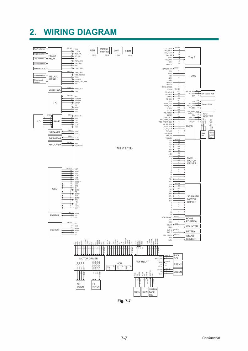
7-7 Confidential
2. WIRING DIAGRAM
Fig. 7-7
Main PCB
LANParallelInterface
CN19 CN9
PH2
CN
22-13
-7 -10
+5V
-5-4-3-2-1
GIJI
CH
RG
RD
PS
PLS
SL
IGND
RL1
RL2/P
OL
TELO
FFV
CC
5
J2LINE
J1EX
T
I24V
-6
CP
-8
Tray2_DET1Tray2_PEDG
+24V
+24V
24VRET
+24V
ZERO_CROSS
VCC24FB_VCLN
Tray2_PE+3.3V
Tray2_SOL
24VRET
S0V+3.3V
+8V
PWM_DEV
T1_PE_SEN
GRIDCFB_DEV
S0V
/TRCV
FB_TRCCV
PWN_TRCC
PWM_CHG
FB_TR
24RET
+24V-8
CN14-9
RELAY_FRONT
REG_SOLMP_SOL+5V
PNEW_SEN
-6-5
-4
-4-3
-7
-11
-9
+24V
Duplex_SOLCN29-2
-1
T1_SOL
TNR_SENS0V
F_COV_SEN
-3-2
-1
CN5-6-5
THM_EDGETHM_CENTERVDD3PO_SEN
-2-1
Duplex_UNIT_SENS0V
BD-7
CN314-8
LD
LD_MONPWNENBLDFALF+5VDATAGND+5VI
FB_GRID
LT2_DET2
FAN_MAIN
MP_PE_SENPEDG_SEN
TNRLED
HU+
REG_REAR_SEN
HV+HU-
HV-
+5VS0V
UU
V
W
HU+HU-
HV+HV-
HW-HW+
+5VS0V
UUVV
WW
FG+FG-
VOG
CCD24VAGND
SH
J3Hand
set
USB
CN13
DIMM
CN18
RELAY_REAR
-4-3
-6-5
-2-1
RESET_NRXDTXDGND+3.3V+5VI
-4-3
CN7-6-5
-2-1
Duplex_SOL
CN3-8
-6-5-4
-7
-3-2-1
Tray 2
CN16-9
-6-5-4
-7
-3-2-1
-8
CN1-22
-18-17-16
-19
-15-14-13
-21-20
-12
-8-7-6
-9
-5-4-3
-11
-2-1
-10
-18-17-16
CN10-19
-15-14-13-12
-8-7-6
-9
-5-4-3
-11
-2-1
-10
LVPS
HEATERONN1
24VRET
HVPS
REG_FRONT_SEN
P1-3
-3-2-1
-2-1
-1-2
-4-3
FAN_PSVCC3.3V
MAINMOTORDRIVER
HW+HW-
U
VV
WW
CN17-14-13-12
-8-7-6
-9
-5-4-3
-11
-2-1
+3.3V
SEN_FBHOMEGND
CN32-3-2-1
-10
SCANNER MOTORDRIVER
-12
S0VC
IC
ML
VC
C24
CN33-20
-7
-10
-5-4-3-2-1
-6
-8
-11
-9
-13
-17-16-15
-18-19
-14
-12
NCU
-7 CN
28-10
-5-4-3-2-1
DP
SE
N1
BS
SO
L2G
ND
DP
SE
N2
+24VB
SS
OL1
-6 -8 -9
GN
DR
SE
NFS
EN
+3.3V
ADF RELAY
CCD
PH1DGND
RSDGND
DGND
SW2SW1
VOB
AE
NA
0
+24VP
0V
NC
+5VP
0VBB
-7 -10
-5-4-3-2-1 -6 -8 -11
-9 -13
CN
26-15-14
-12
MOTOR DRIVER
EN
A1
DE
CAY
STBA
B B
PW
M0
PW
M1
AGND
AGNDVOR
VOUT1VOUT2
CN30-2-1SPEAKER
+3.3VSTHM
CN6-2-1THERMISTOR
GNDFB_COVER
CN24-2-1FB-COVER
+24VCOUNT CN8-2
-1
HOMEPOSITION
COUNTER
BAT_PBAT_N CN23-2
-1 BATTRY
GNDSEN_STACK CN20-3
-2-1
STACKSENSOR+3.3V
CN
2-4-3-2-1 C
N1-4
-3-2-1
FB_O
UT A _
ADFMOTOR
FBMOTOR
-2-1
FSEN
FB_O
UT A
FB_O
UT B
FB_O
UT B_
+3.3V
FSE
N0V
AD
F_OU
T AA
DF_O
UT A
AD
F_OU
T BA
DF_O
UT B _ _
CN
2-3
-2-1
RSEN
+3.3V
RS
EN0V
CN
4-2-1
SWITCHBACKSOL
SB
_SO
L+24V
CN
3-3
-2-1
FSEN2
+3.3V
FSEN2
0V
CN2-3
-2-1
SBSEN
+3.3V
SBSEN
0V
CN5-2-1
PICKSOLPICK_SOL
+24V
CN3-3
FGGNDDATA-DATA++5VFG
-4-3
CN21-6-5
-2-1
USB HOST
DATA++5VFG
-2-1
MAIN FAN
PANEL-4-3
CN3-6-5
-2-1
LCD
CN2-3
MP_RE_SENVCC3.3V
S0V
P2-4S0VVCC3.3V
FAN_MAINFAN_PS
FAN_MAIN_LOCK
P0VTNRLED
T1_SENPEDG_SEN
P3-5
Duplex unit sensor
Fuser thermistor
Tray1 solenoid
Regist solenoid
MP solenoid
Cover sensor
Toner LED PCB
MP sensor PCB
Sensor PCB
Tonersensor PCB
CN
1-3-2-1
FAN
_LOC
K
24_RE
TFA
N_M
AIN
Mainfan
CN
2-2-1
FAN
_PS
24_RE
T
Powersupplyfan

APPENDIX 1WORKER SWITCH (WSW)This appendix describes the functions of the Firmware switches. Use the Firmware switch to match the environmental conditions if the machine malfunctions due to mismatching.
Confidential
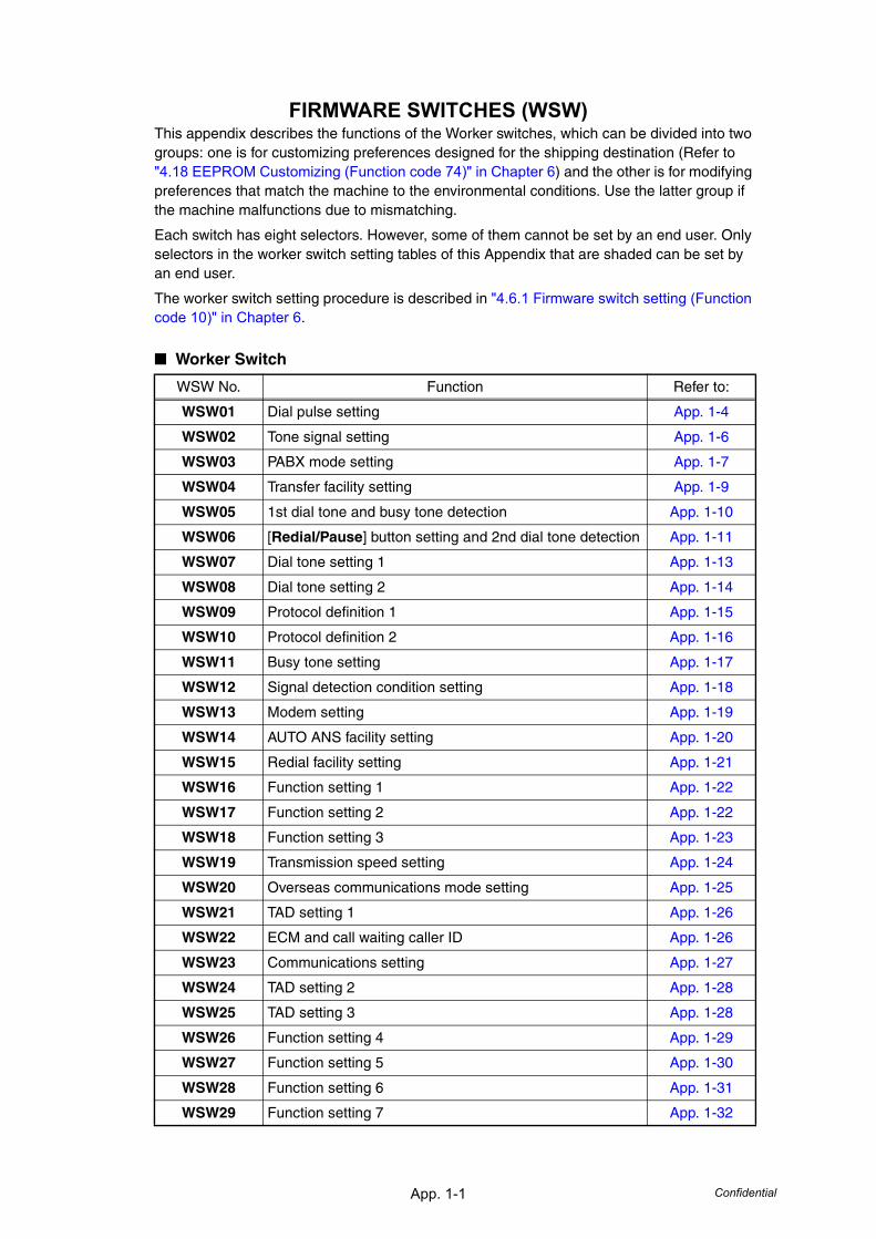
App. 1-1 Confidential
FIRMWARE SWITCHES (WSW)This appendix describes the functions of the Worker switches, which can be divided into two groups: one is for customizing preferences designed for the shipping destination (Refer to "4.18 EEPROM Customizing (Function code 74)" in Chapter 6) and the other is for modifying preferences that match the machine to the environmental conditions. Use the latter group if the machine malfunctions due to mismatching.
Each switch has eight selectors. However, some of them cannot be set by an end user. Only selectors in the worker switch setting tables of this Appendix that are shaded can be set by an end user.
The worker switch setting procedure is described in "4.6.1 Firmware switch setting (Function code 10)" in Chapter 6.
■ Worker Switch
WSW No. Function Refer to:
WSW01 Dial pulse setting App. 1-4
WSW02 Tone signal setting App. 1-6
WSW03 PABX mode setting App. 1-7
WSW04 Transfer facility setting App. 1-9
WSW05 1st dial tone and busy tone detection App. 1-10
WSW06 [Redial/Pause] button setting and 2nd dial tone detection App. 1-11
WSW07 Dial tone setting 1 App. 1-13
WSW08 Dial tone setting 2 App. 1-14
WSW09 Protocol definition 1 App. 1-15
WSW10 Protocol definition 2 App. 1-16
WSW11 Busy tone setting App. 1-17
WSW12 Signal detection condition setting App. 1-18
WSW13 Modem setting App. 1-19
WSW14 AUTO ANS facility setting App. 1-20
WSW15 Redial facility setting App. 1-21
WSW16 Function setting 1 App. 1-22
WSW17 Function setting 2 App. 1-22
WSW18 Function setting 3 App. 1-23
WSW19 Transmission speed setting App. 1-24
WSW20 Overseas communications mode setting App. 1-25
WSW21 TAD setting 1 App. 1-26
WSW22 ECM and call waiting caller ID App. 1-26
WSW23 Communications setting App. 1-27
WSW24 TAD setting 2 App. 1-28
WSW25 TAD setting 3 App. 1-28
WSW26 Function setting 4 App. 1-29
WSW27 Function setting 5 App. 1-30
WSW28 Function setting 6 App. 1-31
WSW29 Function setting 7 App. 1-32
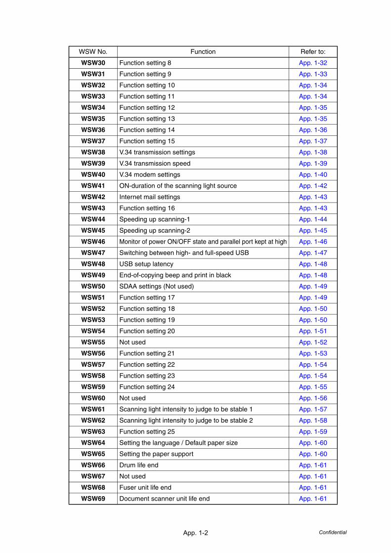
App. 1-2 Confidential
WSW30 Function setting 8 App. 1-32
WSW31 Function setting 9 App. 1-33
WSW32 Function setting 10 App. 1-34
WSW33 Function setting 11 App. 1-34
WSW34 Function setting 12 App. 1-35
WSW35 Function setting 13 App. 1-35
WSW36 Function setting 14 App. 1-36
WSW37 Function setting 15 App. 1-37
WSW38 V.34 transmission settings App. 1-38
WSW39 V.34 transmission speed App. 1-39
WSW40 V.34 modem settings App. 1-40
WSW41 ON-duration of the scanning light source App. 1-42
WSW42 Internet mail settings App. 1-43
WSW43 Function setting 16 App. 1-43
WSW44 Speeding up scanning-1 App. 1-44
WSW45 Speeding up scanning-2 App. 1-45
WSW46 Monitor of power ON/OFF state and parallel port kept at high App. 1-46
WSW47 Switching between high- and full-speed USB App. 1-47
WSW48 USB setup latency App. 1-48
WSW49 End-of-copying beep and print in black App. 1-48
WSW50 SDAA settings (Not used) App. 1-49
WSW51 Function setting 17 App. 1-49
WSW52 Function setting 18 App. 1-50
WSW53 Function setting 19 App. 1-50
WSW54 Function setting 20 App. 1-51
WSW55 Not used App. 1-52
WSW56 Function setting 21 App. 1-53
WSW57 Function setting 22 App. 1-54
WSW58 Function setting 23 App. 1-54
WSW59 Function setting 24 App. 1-55
WSW60 Not used App. 1-56
WSW61 Scanning light intensity to judge to be stable 1 App. 1-57
WSW62 Scanning light intensity to judge to be stable 2 App. 1-58
WSW63 Function setting 25 App. 1-59
WSW64 Setting the language / Default paper size App. 1-60
WSW65 Setting the paper support App. 1-60
WSW66 Drum life end App. 1-61
WSW67 Not used App. 1-61
WSW68 Fuser unit life end App. 1-61
WSW69 Document scanner unit life end App. 1-61
WSW No. Function Refer to:

App. 1-3 Confidential
WSW70 Paper feeding kit life end App. 1-61
WSW71 Paper feeding kit 2 life end App. 1-61
WSW72 Paper feeding kit MP life end App. 1-62
WSW73 Not used App. 1-62
WSW74 Not used App. 1-62
WSW75 Paper ejecting distance of the switch back App. 1-63
WSW76 The limited number of the documents in reverse for paper ejection of the simplex scanning from ADF App. 1-64
WSW77 The limited number of the documents in reverse for paper ejection of the duplex scanning from ADF App. 1-64
WSW No. Function Refer to:
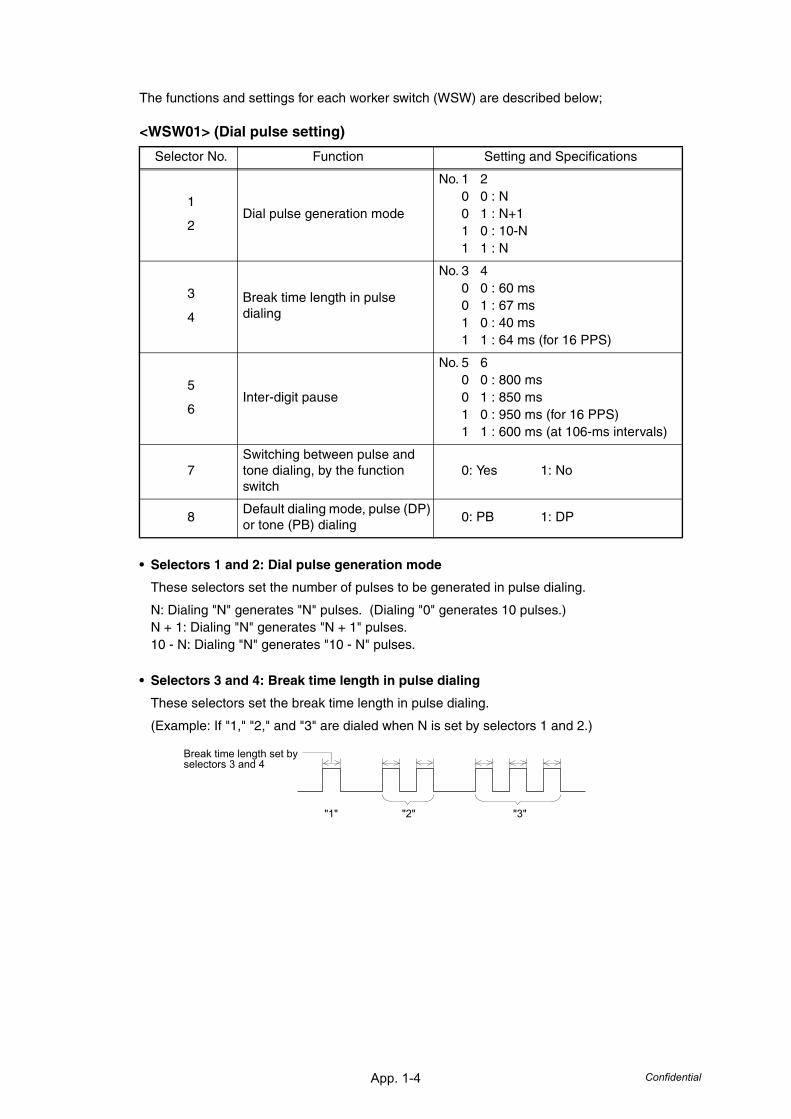
App. 1-4 Confidential
The functions and settings for each worker switch (WSW) are described below;
<WSW01> (Dial pulse setting)
• Selectors 1 and 2: Dial pulse generation mode
These selectors set the number of pulses to be generated in pulse dialing.
N: Dialing "N" generates "N" pulses. (Dialing "0" generates 10 pulses.)N + 1: Dialing "N" generates "N + 1" pulses.10 - N: Dialing "N" generates "10 - N" pulses.
• Selectors 3 and 4: Break time length in pulse dialing
These selectors set the break time length in pulse dialing.
(Example: If "1," "2," and "3" are dialed when N is set by selectors 1 and 2.)
Selector No. Function Setting and Specifications
1
2Dial pulse generation mode
No. 1 20 0 : N0 1 : N+11 0 : 10-N1 1 : N
3
4
Break time length in pulse dialing
No. 3 40 0 : 60 ms0 1 : 67 ms1 0 : 40 ms 1 1 : 64 ms (for 16 PPS)
5
6Inter-digit pause
No. 5 60 0 : 800 ms0 1 : 850 ms1 0 : 950 ms (for 16 PPS)1 1 : 600 ms (at 106-ms intervals)
7Switching between pulse and tone dialing, by the function switch
0: Yes 1: No
8Default dialing mode, pulse (DP) or tone (PB) dialing
0: PB 1: DP
"1" "2" "3"
Break time length set by selectors 3 and 4
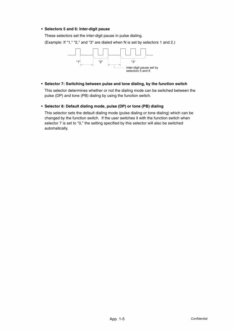
App. 1-5 Confidential
• Selectors 5 and 6: Inter-digit pause
These selectors set the inter-digit pause in pulse dialing.
(Example: If "1," "2," and "3" are dialed when N is set by selectors 1 and 2.)
• Selector 7: Switching between pulse and tone dialing, by the function switch
This selector determines whether or not the dialing mode can be switched between the pulse (DP) and tone (PB) dialing by using the function switch.
• Selector 8: Default dialing mode, pulse (DP) or tone (PB) dialing
This selector sets the default dialing mode (pulse dialing or tone dialing) which can be changed by the function switch. If the user switches it with the function switch when selector 7 is set to "0," the setting specified by this selector will also be switched automatically.
"1" "2" "3"
Inter-digit pause set by selectors 5 and 6
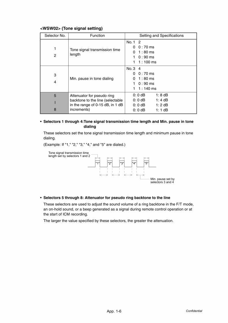
App. 1-6 Confidential
<WSW02> (Tone signal setting)
• Selectors 1 through 4:Tone signal transmission time length and Min. pause in tone dialing
These selectors set the tone signal transmission time length and minimum pause in tone dialing.
(Example: If "1," "2," "3," "4," and "5" are dialed.)
• Selectors 5 through 8: Attenuator for pseudo ring backtone to the line
These selectors are used to adjust the sound volume of a ring backtone in the F/T mode, an on-hold sound, or a beep generated as a signal during remote control operation or at the start of ICM recording.
The larger the value specified by these selectors, the greater the attenuation.
Selector No. Function Setting and Specifications
1
2
Tone signal transmission time length
No. 1 20 0 : 70 ms0 1 : 80 ms1 0 : 90 ms1 1 : 100 ms
3
4Min. pause in tone dialing
No. 3 40 0 : 70 ms0 1 : 80 ms1 0 : 90 ms1 1 : 140 ms
5
I
8
Attenuator for pseudo ring backtone to the line (selectable in the range of 0-15 dB, in 1 dB increments)
0: 0 dB 1: 8 dB0: 0 dB 1: 4 dB0: 0 dB 1: 2 dB0: 0 dB 1: 1 dB
"1" "2" "3" "4" "5"
Min. pause set by selectors 3 and 4
Tone signal transmission time length set by selectors 1 and 2
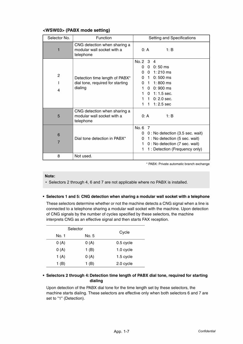
App. 1-7 Confidential
<WSW03> (PABX mode setting)
* PABX: Private automatic branch exchange
• Selectors 1 and 5: CNG detection when sharing a modular wall socket with a telephone
These selectors determine whether or not the machine detects a CNG signal when a line is connected to a telephone sharing a modular wall socket with the machine. Upon detection of CNG signals by the number of cycles specified by these selectors, the machine interprets CNG as an effective signal and then starts FAX reception.
• Selectors 2 through 4:Detection time length of PABX dial tone, required for starting dialing
Upon detection of the PABX dial tone for the time length set by these selectors, the machine starts dialing. These selectors are effective only when both selectors 6 and 7 are set to "1" (Detection).
Selector No. Function Setting and Specifications
1CNG detection when sharing a modular wall socket with a telephone
0: A 1: B
2
I
4
Detection time length of PABX* dial tone, required for starting dialing
No. 2 3 40 0 0: 50 ms0 0 1: 210 ms0 1 0: 500 ms0 1 1: 800 ms1 0 0: 900 ms1 0 1: 1.5 sec.1 1 0: 2.0 sec.1 1 1: 2.5 sec
5CNG detection when sharing a modular wall socket with a telephone
0: A 1: B
6
7Dial tone detection in PABX*
No. 6 70 0 : No detection (3.5 sec. wait)0 1 : No detection (5 sec. wait)1 0 : No detection (7 sec. wait)1 1 : Detection (Frequency only)
8 Not used.
Note:• Selectors 2 through 4, 6 and 7 are not applicable where no PABX is installed.
SelectorCycle
No. 1 No. 5
0 (A) 0 (A) 0.5 cycle
0 (A) 1 (B) 1.0 cycle
1 (A) 0 (A) 1.5 cycle
1 (B) 1 (B) 2.0 cycle

App. 1-8 Confidential
• Selectors 6 and 7: Dial tone detection in PABX*
These selectors activate or deactivate the dial tone detection function which detects a dial tone when a line is connected to the PABX.
Setting both of these selectors to "1" activates the dial tone detection function so that the machine starts dialing upon detection of a dial tone when a line is connected.
Other setting combinations deactivate the dial tone detection function so that the machine starts dialing after the specified WAIT (3.5, 5.0, or 7.0 sec.) without detection of a dial tone when a line is connected.
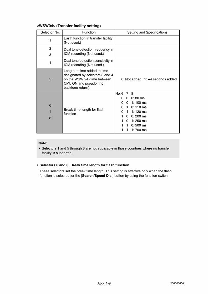
App. 1-9 Confidential
<WSW04> (Transfer facility setting)
• Selectors 6 and 8: Break time length for flash function
These selectors set the break time length. This setting is effective only when the flash function is selected for the [Search/Speed Dial] button by using the function switch.
Selector No. Function Setting and Specifications
1Earth function in transfer facility (Not used.)
2
3
Dual tone detection frequency in ICM recording (Not used.)
4Dual tone detection sensitivity in ICM recording (Not used.)
5
Length of time added to time designated by selectors 3 and 4 on the WSW 24 (time between CML ON and pseudo ring backtone return).
0: Not added 1: +4 seconds added
6
I
8
Break time length for flash function
No. 6 7 80 0 0: 80 ms0 0 1: 100 ms0 1 0: 110 ms0 1 1: 120 ms1 0 0: 200 ms1 0 1: 250 ms1 1 0: 500 ms1 1 1: 700 ms
Note:• Selectors 1 and 5 through 8 are not applicable in those countries where no transfer
facility is supported.
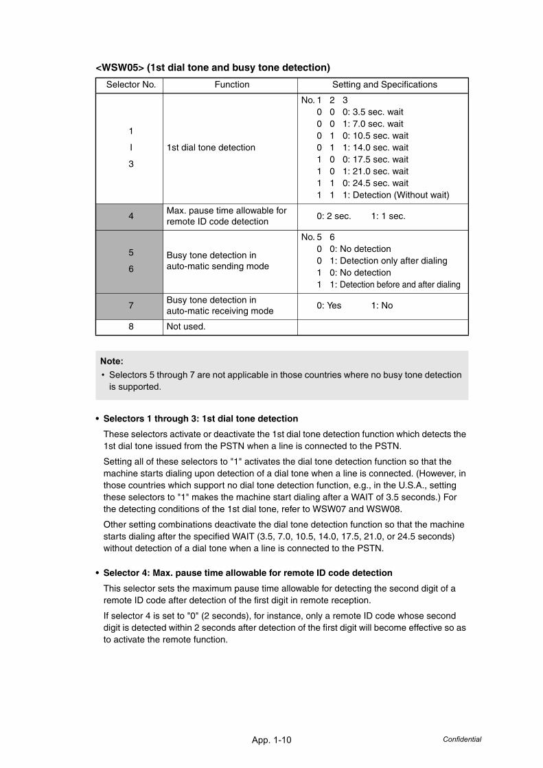
App. 1-10 Confidential
<WSW05> (1st dial tone and busy tone detection)
• Selectors 1 through 3: 1st dial tone detection
These selectors activate or deactivate the 1st dial tone detection function which detects the 1st dial tone issued from the PSTN when a line is connected to the PSTN.
Setting all of these selectors to "1" activates the dial tone detection function so that the machine starts dialing upon detection of a dial tone when a line is connected. (However, in those countries which support no dial tone detection function, e.g., in the U.S.A., setting these selectors to "1" makes the machine start dialing after a WAIT of 3.5 seconds.) For the detecting conditions of the 1st dial tone, refer to WSW07 and WSW08.
Other setting combinations deactivate the dial tone detection function so that the machine starts dialing after the specified WAIT (3.5, 7.0, 10.5, 14.0, 17.5, 21.0, or 24.5 seconds) without detection of a dial tone when a line is connected to the PSTN.
• Selector 4: Max. pause time allowable for remote ID code detection
This selector sets the maximum pause time allowable for detecting the second digit of a remote ID code after detection of the first digit in remote reception.
If selector 4 is set to "0" (2 seconds), for instance, only a remote ID code whose second digit is detected within 2 seconds after detection of the first digit will become effective so as to activate the remote function.
Selector No. Function Setting and Specifications
1
I
3
1st dial tone detection
No. 1 2 30 0 0: 3.5 sec. wait0 0 1: 7.0 sec. wait0 1 0: 10.5 sec. wait0 1 1: 14.0 sec. wait1 0 0: 17.5 sec. wait1 0 1: 21.0 sec. wait1 1 0: 24.5 sec. wait1 1 1: Detection (Without wait)
4Max. pause time allowable for remote ID code detection
0: 2 sec. 1: 1 sec.
5
6
Busy tone detection in auto-matic sending mode
No. 5 60 0: No detection0 1: Detection only after dialing1 0: No detection1 1: Detection before and after dialing
7Busy tone detection in auto-matic receiving mode
0: Yes 1: No
8 Not used.
Note:• Selectors 5 through 7 are not applicable in those countries where no busy tone detection
is supported.
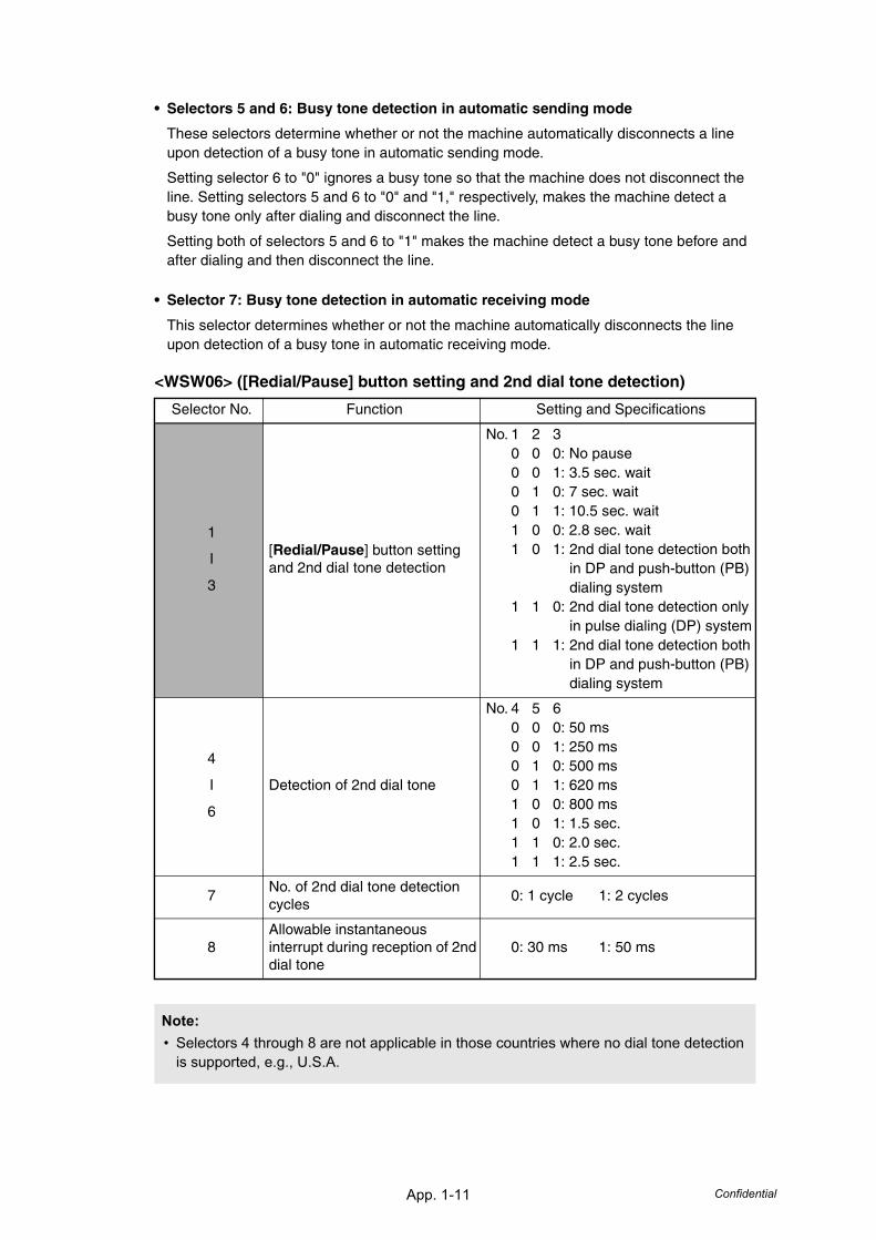
App. 1-11 Confidential
• Selectors 5 and 6: Busy tone detection in automatic sending mode
These selectors determine whether or not the machine automatically disconnects a line upon detection of a busy tone in automatic sending mode.
Setting selector 6 to "0" ignores a busy tone so that the machine does not disconnect the line. Setting selectors 5 and 6 to "0" and "1," respectively, makes the machine detect a busy tone only after dialing and disconnect the line.
Setting both of selectors 5 and 6 to "1" makes the machine detect a busy tone before and after dialing and then disconnect the line.
• Selector 7: Busy tone detection in automatic receiving mode
This selector determines whether or not the machine automatically disconnects the line upon detection of a busy tone in automatic receiving mode.
<WSW06> ([Redial/Pause] button setting and 2nd dial tone detection)
Selector No. Function Setting and Specifications
1
I
3
[Redial/Pause] button setting and 2nd dial tone detection
No. 1 2 30 0 0: No pause0 0 1: 3.5 sec. wait0 1 0: 7 sec. wait0 1 1: 10.5 sec. wait1 0 0: 2.8 sec. wait1 0 1: 2nd dial tone detection both
in DP and push-button (PB) dialing system
1 1 0: 2nd dial tone detection only in pulse dialing (DP) system
1 1 1: 2nd dial tone detection both in DP and push-button (PB) dialing system
4
I
6
Detection of 2nd dial tone
No. 4 5 60 0 0: 50 ms0 0 1: 250 ms0 1 0: 500 ms0 1 1: 620 ms1 0 0: 800 ms1 0 1: 1.5 sec.1 1 0: 2.0 sec.1 1 1: 2.5 sec.
7No. of 2nd dial tone detection cycles
0: 1 cycle 1: 2 cycles
8Allowable instantaneous interrupt during reception of 2nd dial tone
0: 30 ms 1: 50 ms
Note:• Selectors 4 through 8 are not applicable in those countries where no dial tone detection
is supported, e.g., U.S.A.

App. 1-12 Confidential
• Selectors 1 through 3: [Redial/Pause] button setting and 2nd dial tone detection
• Selectors 4 through 6: Detection of 2nd dial tone
Upon detection of the 2nd dial tone for the time length specified by these selectors, the machine starts dialing.This setting is effective only when the 2nd dial tone detection function is activated by selectors 1 through 3 (Setting 101, 110, or 111).This function does not apply in those countries where no dial tone detection function is supported.
• Selector 7: No. of 2nd dial tone detection cycles
This selector sets the number of dial tone detection cycles required for starting dialing.
• Selector 8: Allowable instantaneous interrupt during reception of 2nd dial tone
This selector sets the allowable instantaneous interrupt period that should be ignored during reception of the 2nd dial tone.
Selectors
1 2 3
0 0 0 No wait is inserted even if the [Redial/Pause] button is pressed.
0 0 1
0 1 0
0 1 1
1 0 0
If you press the [Redial/Pause] button during dialing, the machine will insert wait as defined in the above table.
If the [Redial/Pause] button is pressed repeatedly, the machine inserts the specified wait multiplied by the number of depressions. It applies also in hook-up dialing.
1 0 1
1 1 0
1 1 1
When these selectors are set to "1, 0, 1":
Each time you press the [Redial/Pause] button in dialing, the machine will wait for the 2nd dial tone to be sent via the communications line regardless of pulse dialing or tone dialing.
When these selectors are set to "1, 1, 0":
If you press the [Redial/Pause] button in pulse dialing, the machine will first wait for the 2nd dial tone to be sent via the communications line. After that, pressing the [Redial/Pause] button will cause the machine to insert a WAIT of 3.5 seconds. In tone dialing, the machine will insert a WAIT of 3.5 seconds.
When these selectors are set to "1, 1, 1":
If you press the [Redial/Pause] button, the machine will first wait for the 2nd dial tone to be sent via the communications line regardless of pulse dialing or tone dialing. After that, pressing the [Redial/Pause] button will cause the machine to insert a wait of 3.5 seconds.
((In those countries where no dial tone detection function is supported, setting these selectors to "1, 0, 1," "1, 1, 0," or "1, 1, 1" inserts a wait of 3.5 seconds.)
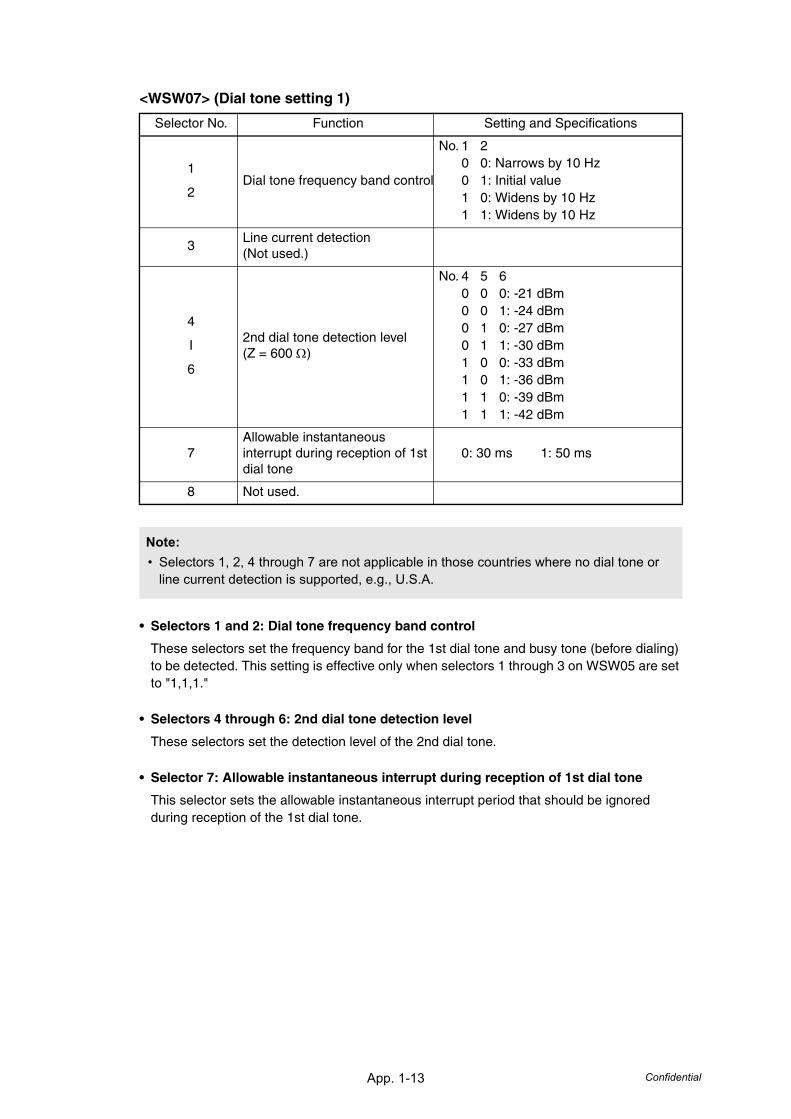
App. 1-13 Confidential
<WSW07> (Dial tone setting 1)
• Selectors 1 and 2: Dial tone frequency band control
These selectors set the frequency band for the 1st dial tone and busy tone (before dialing) to be detected. This setting is effective only when selectors 1 through 3 on WSW05 are set to "1,1,1."
• Selectors 4 through 6: 2nd dial tone detection level
These selectors set the detection level of the 2nd dial tone.
• Selector 7: Allowable instantaneous interrupt during reception of 1st dial tone
This selector sets the allowable instantaneous interrupt period that should be ignored during reception of the 1st dial tone.
Selector No. Function Setting and Specifications
1
2Dial tone frequency band control
No. 1 20 0: Narrows by 10 Hz0 1: Initial value1 0: Widens by 10 Hz1 1: Widens by 10 Hz
3Line current detection (Not used.)
4
I
6
2nd dial tone detection level(Z = 600 Ω)
No. 4 5 60 0 0: -21 dBm0 0 1: -24 dBm0 1 0: -27 dBm0 1 1: -30 dBm1 0 0: -33 dBm1 0 1: -36 dBm1 1 0: -39 dBm1 1 1: -42 dBm
7Allowable instantaneous interrupt during reception of 1st dial tone
0: 30 ms 1: 50 ms
8 Not used.
Note:• Selectors 1, 2, 4 through 7 are not applicable in those countries where no dial tone or
line current detection is supported, e.g., U.S.A.
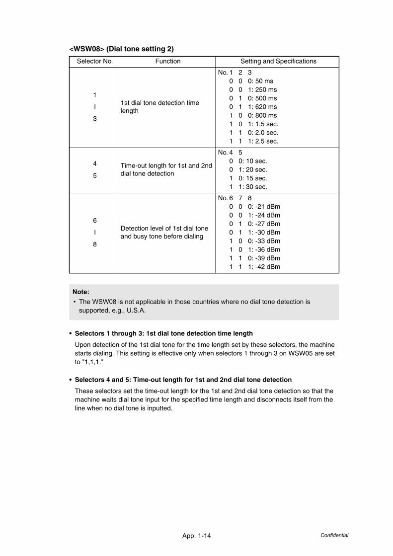
App. 1-14 Confidential
<WSW08> (Dial tone setting 2)
• Selectors 1 through 3: 1st dial tone detection time length
Upon detection of the 1st dial tone for the time length set by these selectors, the machine starts dialing. This setting is effective only when selectors 1 through 3 on WSW05 are set to "1,1,1."
• Selectors 4 and 5: Time-out length for 1st and 2nd dial tone detection
These selectors set the time-out length for the 1st and 2nd dial tone detection so that the machine waits dial tone input for the specified time length and disconnects itself from the line when no dial tone is inputted.
Selector No. Function Setting and Specifications
1
I
3
1st dial tone detection time length
No. 1 2 30 0 0: 50 ms0 0 1: 250 ms0 1 0: 500 ms0 1 1: 620 ms1 0 0: 800 ms1 0 1: 1.5 sec.1 1 0: 2.0 sec.1 1 1: 2.5 sec.
4
5
Time-out length for 1st and 2nd dial tone detection
No. 4 50 0: 10 sec.0 1: 20 sec.1 0: 15 sec.1 1: 30 sec.
6
I
8
Detection level of 1st dial tone and busy tone before dialing
No. 6 7 80 0 0: -21 dBm0 0 1: -24 dBm0 1 0: -27 dBm0 1 1: -30 dBm1 0 0: -33 dBm1 0 1: -36 dBm1 1 0: -39 dBm1 1 1: -42 dBm
Note:• The WSW08 is not applicable in those countries where no dial tone detection is
supported, e.g., U.S.A.
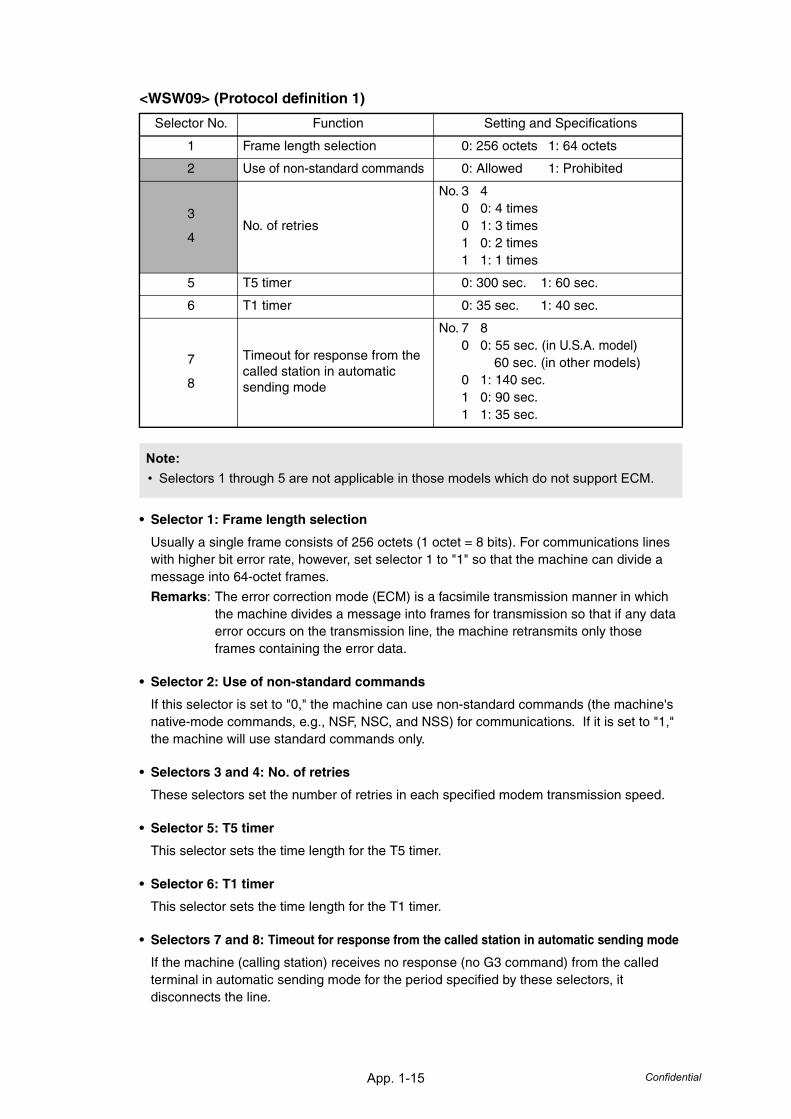
App. 1-15 Confidential
<WSW09> (Protocol definition 1)
• Selector 1: Frame length selection
Usually a single frame consists of 256 octets (1 octet = 8 bits). For communications lines with higher bit error rate, however, set selector 1 to "1" so that the machine can divide a message into 64-octet frames.
Remarks: The error correction mode (ECM) is a facsimile transmission manner in which the machine divides a message into frames for transmission so that if any data error occurs on the transmission line, the machine retransmits only those frames containing the error data.
• Selector 2: Use of non-standard commands
If this selector is set to "0," the machine can use non-standard commands (the machine's native-mode commands, e.g., NSF, NSC, and NSS) for communications. If it is set to "1," the machine will use standard commands only.
• Selectors 3 and 4: No. of retries
These selectors set the number of retries in each specified modem transmission speed.
• Selector 5: T5 timer
This selector sets the time length for the T5 timer.
• Selector 6: T1 timer
This selector sets the time length for the T1 timer.
• Selectors 7 and 8: Timeout for response from the called station in automatic sending mode
If the machine (calling station) receives no response (no G3 command) from the called terminal in automatic sending mode for the period specified by these selectors, it disconnects the line.
Selector No. Function Setting and Specifications
1 Frame length selection 0: 256 octets 1: 64 octets
2 Use of non-standard commands 0: Allowed 1: Prohibited
3
4No. of retries
No. 3 40 0: 4 times0 1: 3 times1 0: 2 times1 1: 1 times
5 T5 timer 0: 300 sec. 1: 60 sec.
6 T1 timer 0: 35 sec. 1: 40 sec.
7
8
Timeout for response from the called station in automatic sending mode
No. 7 80 0: 55 sec. (in U.S.A. model)
60 sec. (in other models)0 1: 140 sec.1 0: 90 sec.1 1: 35 sec.
Note:• Selectors 1 through 5 are not applicable in those models which do not support ECM.
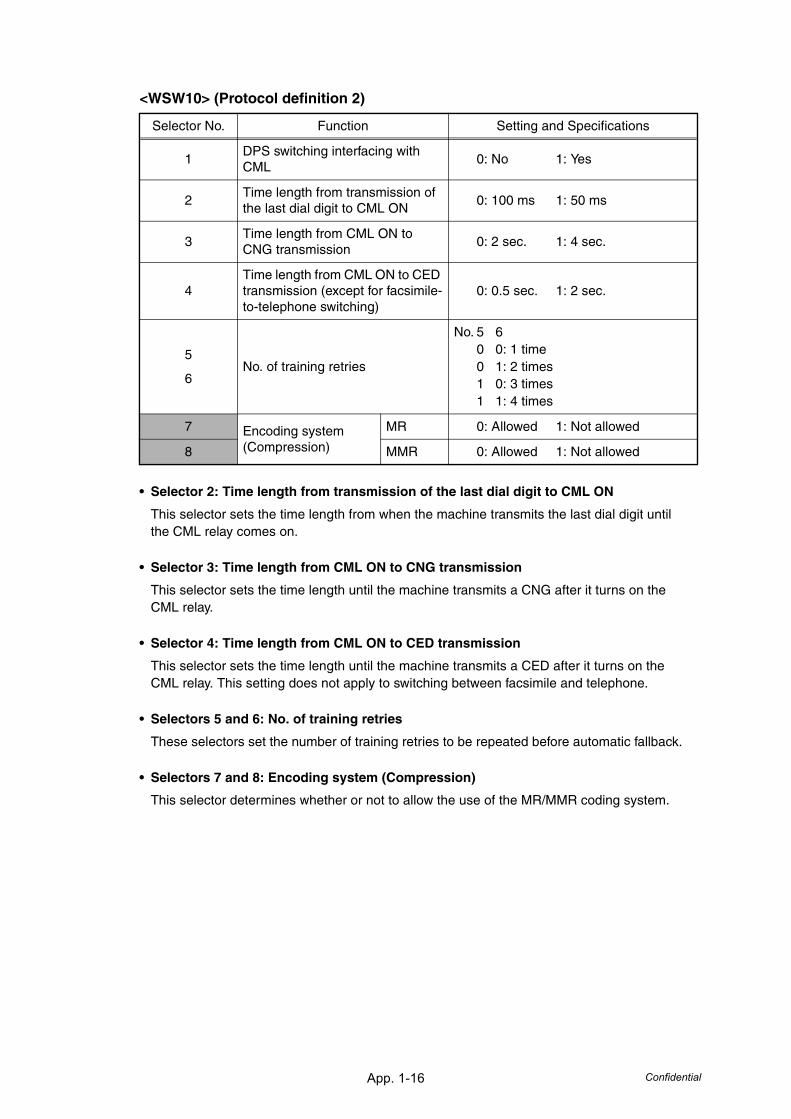
App. 1-16 Confidential
<WSW10> (Protocol definition 2)
• Selector 2: Time length from transmission of the last dial digit to CML ON
This selector sets the time length from when the machine transmits the last dial digit until the CML relay comes on.
• Selector 3: Time length from CML ON to CNG transmission
This selector sets the time length until the machine transmits a CNG after it turns on the CML relay.
• Selector 4: Time length from CML ON to CED transmission
This selector sets the time length until the machine transmits a CED after it turns on the CML relay. This setting does not apply to switching between facsimile and telephone.
• Selectors 5 and 6: No. of training retries
These selectors set the number of training retries to be repeated before automatic fallback.
• Selectors 7 and 8: Encoding system (Compression)
This selector determines whether or not to allow the use of the MR/MMR coding system.
Selector No. Function Setting and Specifications
1DPS switching interfacing with CML
0: No 1: Yes
2Time length from transmission of the last dial digit to CML ON
0: 100 ms 1: 50 ms
3Time length from CML ON to CNG transmission
0: 2 sec. 1: 4 sec.
4Time length from CML ON to CED transmission (except for facsimile-to-telephone switching)
0: 0.5 sec. 1: 2 sec.
5
6No. of training retries
No. 5 60 0: 1 time0 1: 2 times1 0: 3 times1 1: 4 times
7 Encoding system(Compression)
MR 0: Allowed 1: Not allowed
8 MMR 0: Allowed 1: Not allowed
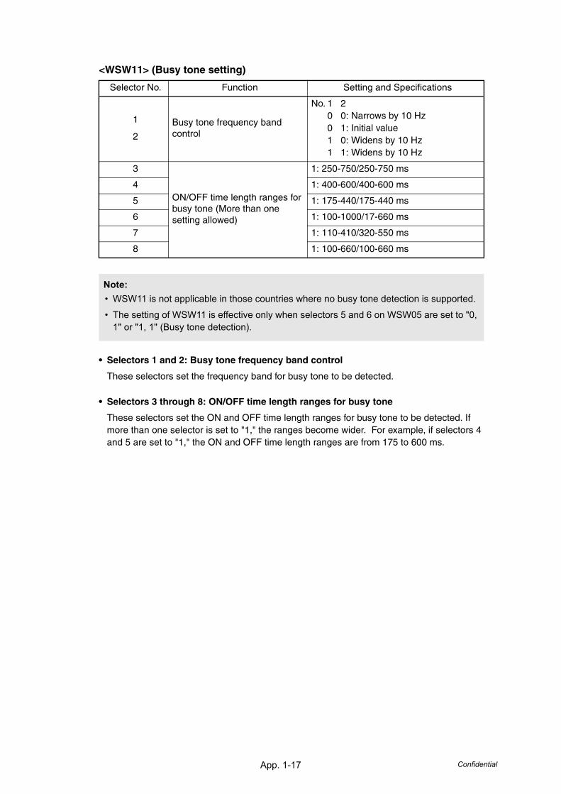
App. 1-17 Confidential
<WSW11> (Busy tone setting)
• Selectors 1 and 2: Busy tone frequency band control
These selectors set the frequency band for busy tone to be detected.
• Selectors 3 through 8: ON/OFF time length ranges for busy tone
These selectors set the ON and OFF time length ranges for busy tone to be detected. If more than one selector is set to "1," the ranges become wider. For example, if selectors 4 and 5 are set to "1," the ON and OFF time length ranges are from 175 to 600 ms.
Selector No. Function Setting and Specifications
1
2
Busy tone frequency band control
No. 1 20 0: Narrows by 10 Hz0 1: Initial value1 0: Widens by 10 Hz1 1: Widens by 10 Hz
3
ON/OFF time length ranges for busy tone (More than one setting allowed)
1: 250-750/250-750 ms
4 1: 400-600/400-600 ms
5 1: 175-440/175-440 ms
6 1: 100-1000/17-660 ms
7 1: 110-410/320-550 ms
8 1: 100-660/100-660 ms
Note:• WSW11 is not applicable in those countries where no busy tone detection is supported.
• The setting of WSW11 is effective only when selectors 5 and 6 on WSW05 are set to "0, 1" or "1, 1" (Busy tone detection).
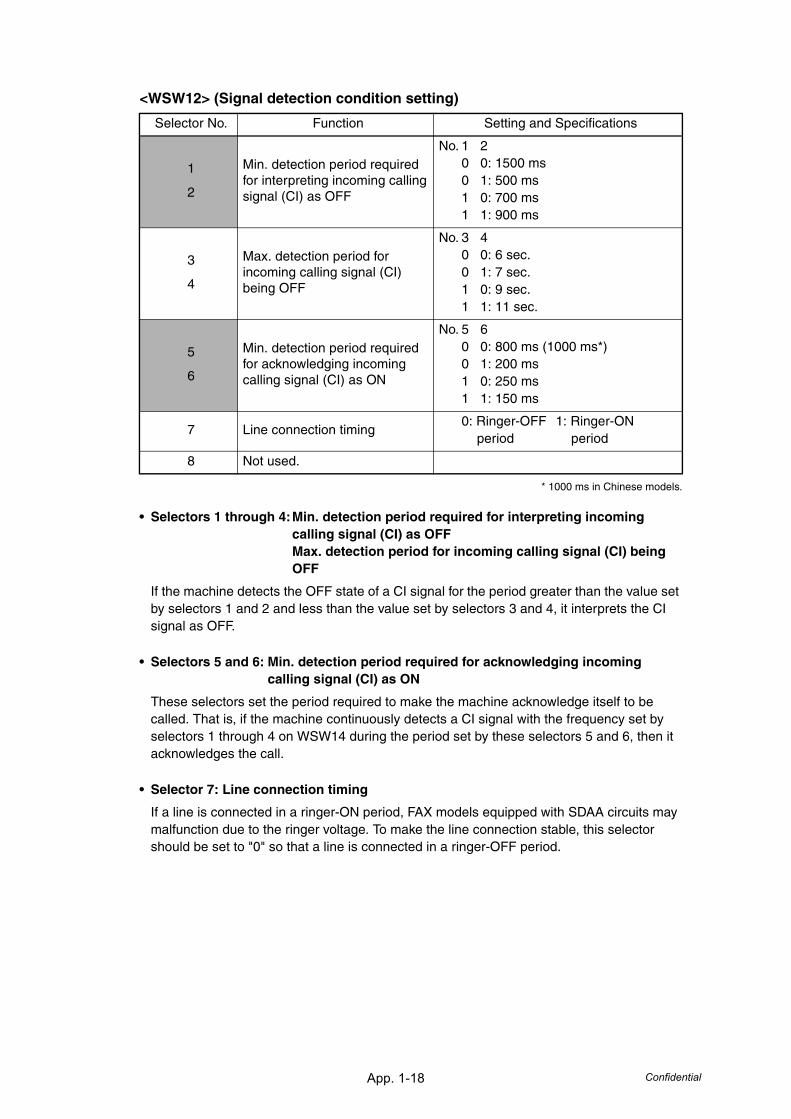
App. 1-18 Confidential
<WSW12> (Signal detection condition setting)
* 1000 ms in Chinese models.
• Selectors 1 through 4:Min. detection period required for interpreting incoming calling signal (CI) as OFFMax. detection period for incoming calling signal (CI) being OFF
If the machine detects the OFF state of a CI signal for the period greater than the value set by selectors 1 and 2 and less than the value set by selectors 3 and 4, it interprets the CI signal as OFF.
• Selectors 5 and 6: Min. detection period required for acknowledging incoming calling signal (CI) as ON
These selectors set the period required to make the machine acknowledge itself to be called. That is, if the machine continuously detects a CI signal with the frequency set by selectors 1 through 4 on WSW14 during the period set by these selectors 5 and 6, then it acknowledges the call.
• Selector 7: Line connection timing
If a line is connected in a ringer-ON period, FAX models equipped with SDAA circuits may malfunction due to the ringer voltage. To make the line connection stable, this selector should be set to "0" so that a line is connected in a ringer-OFF period.
Selector No. Function Setting and Specifications
1
2
Min. detection period required for interpreting incoming calling signal (CI) as OFF
No. 1 20 0: 1500 ms0 1: 500 ms1 0: 700 ms1 1: 900 ms
3
4
Max. detection period for incoming calling signal (CI) being OFF
No. 3 40 0: 6 sec.0 1: 7 sec.1 0: 9 sec.1 1: 11 sec.
5
6
Min. detection period required for acknowledging incoming calling signal (CI) as ON
No. 5 60 0: 800 ms (1000 ms*)0 1: 200 ms1 0: 250 ms1 1: 150 ms
7 Line connection timing0: Ringer-OFF 1: Ringer-ON period period
8 Not used.
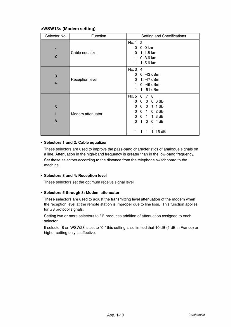
App. 1-19 Confidential
<WSW13> (Modem setting)
• Selectors 1 and 2: Cable equalizer
These selectors are used to improve the pass-band characteristics of analogue signals on a line. Attenuation in the high-band frequency is greater than in the low-band frequency.
Set these selectors according to the distance from the telephone switchboard to the machine.
• Selectors 3 and 4: Reception level
These selectors set the optimum receive signal level.
• Selectors 5 through 8: Modem attenuator
These selectors are used to adjust the transmitting level attenuation of the modem when the reception level at the remote station is improper due to line loss. This function applies for G3 protocol signals.
Setting two or more selectors to "1" produces addition of attenuation assigned to each selector.
If selector 8 on WSW23 is set to "0," this setting is so limited that 10 dB (1 dB in France) or higher setting only is effective.
Selector No. Function Setting and Specifications
1
2Cable equalizer
No. 1 20 0: 0 km0 1: 1.8 km1 0: 3.6 km1 1: 5.6 km
3
4Reception level
No. 3 40 0: -43 dBm0 1: -47 dBm1 0: -49 dBm1 1: -51 dBm
5
I
8
Modem attenuator
No. 5 6 7 80 0 0 0: 0 dB0 0 0 1: 1 dB0 0 1 0: 2 dB0 0 1 1: 3 dB0 1 0 0: 4 dB
1 1 1 1: 15 dB
....
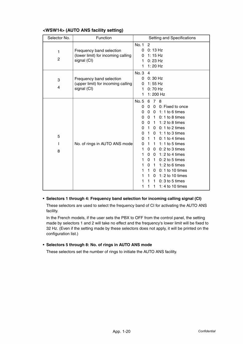
App. 1-20 Confidential
<WSW14> (AUTO ANS facility setting)
• Selectors 1 through 4: Frequency band selection for incoming calling signal (CI)
These selectors are used to select the frequency band of CI for activating the AUTO ANS facility.
In the French models, if the user sets the PBX to OFF from the control panel, the setting made by selectors 1 and 2 will take no effect and the frequency's lower limit will be fixed to 32 Hz. (Even if the setting made by these selectors does not apply, it will be printed on the configuration list.)
• Selectors 5 through 8: No. of rings in AUTO ANS mode
These selectors set the number of rings to initiate the AUTO ANS facility.
Selector No. Function Setting and Specifications
1
2
Frequency band selection (lower limit) for incoming calling signal (CI)
No. 1 20 0: 13 Hz0 1: 15 Hz1 0: 23 Hz1 1: 20 Hz
3
4
Frequency band selection (upper limit) for incoming calling signal (CI)
No. 3 40 0: 30 Hz0 1: 55 Hz1 0: 70 Hz1 1: 200 Hz
5
I
8
No. of rings in AUTO ANS mode
No. 5 6 7 80 0 0 0: Fixed to once0 0 0 1: 1 to 6 times0 0 1 0: 1 to 8 times0 0 1 1: 2 to 8 times0 1 0 0: 1 to 2 times0 1 0 1: 1 to 3 times0 1 1 0: 1 to 4 times0 1 1 1: 1 to 5 times1 0 0 0: 2 to 3 times1 0 0 1: 2 to 4 times1 0 1 0: 2 to 5 times1 0 1 1: 2 to 6 times1 1 0 0: 1 to 10 times1 1 0 1: 2 to 10 times1 1 1 0: 3 to 5 times1 1 1 1: 4 to 10 times
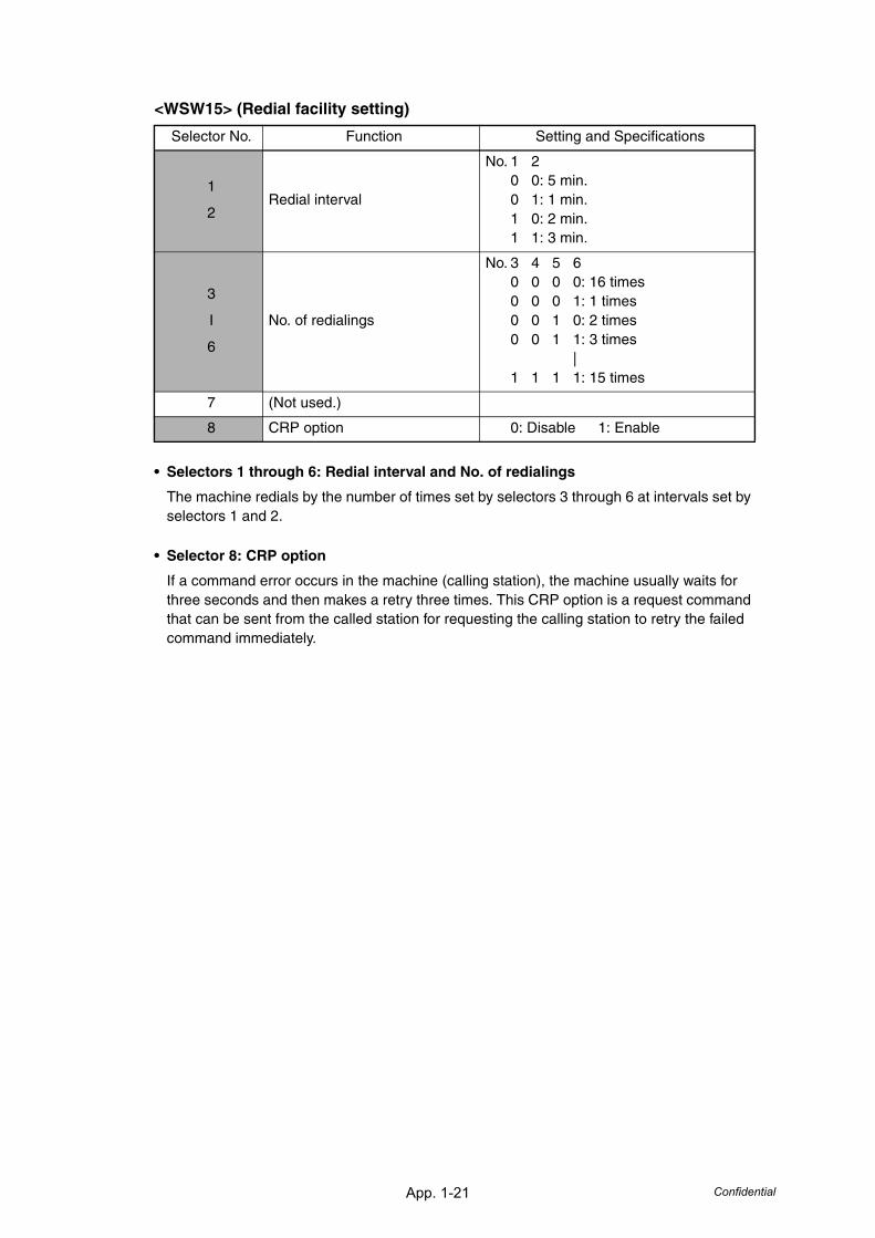
App. 1-21 Confidential
<WSW15> (Redial facility setting)
• Selectors 1 through 6: Redial interval and No. of redialings
The machine redials by the number of times set by selectors 3 through 6 at intervals set by selectors 1 and 2.
• Selector 8: CRP option
If a command error occurs in the machine (calling station), the machine usually waits for three seconds and then makes a retry three times. This CRP option is a request command that can be sent from the called station for requesting the calling station to retry the failed command immediately.
Selector No. Function Setting and Specifications
1
2Redial interval
No. 1 20 0: 5 min.0 1: 1 min.1 0: 2 min.1 1: 3 min.
3
I
6
No. of redialings
No. 3 4 5 60 0 0 0: 16 times0 0 0 1: 1 times0 0 1 0: 2 times0 0 1 1: 3 times
|1 1 1 1: 15 times
7 (Not used.)
8 CRP option 0: Disable 1: Enable
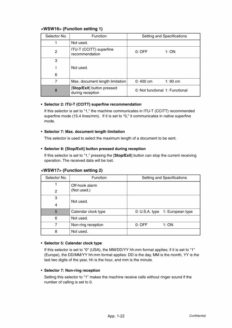
App. 1-22 Confidential
<WSW16> (Function setting 1)
• Selector 2: ITU-T (CCITT) superfine recommendation
If this selector is set to "1," the machine communicates in ITU-T (CCITT) recommended superfine mode (15.4 lines/mm). If it is set to "0," it communicates in native superfine mode.
• Selector 7: Max. document length limitation
This selector is used to select the maximum length of a document to be sent.
• Selector 8: [Stop/Exit] button pressed during reception
If this selector is set to "1," pressing the [Stop/Exit] button can stop the current receiving operation. The received data will be lost.
<WSW17> (Function setting 2)
• Selector 5: Calendar clock type
If this selector is set to "0" (USA), the MM/DD/YY hh:mm format applies; if it is set to "1" (Europe), the DD/MM/YY hh:mm format applies: DD is the day, MM is the month, YY is the last two digits of the year, hh is the hour, and mm is the minute.
• Selector 7: Non-ring reception
Setting this selector to "1" makes the machine receive calls without ringer sound if the number of calling is set to 0.
Selector No. Function Setting and Specifications
1 Not used.
2ITU-T (CCITT) superfine recommendation
0: OFF 1: ON
3
I
6
Not used.
7 Max. document length limitation 0: 400 cm 1: 90 cm
8[Stop/Exit] button pressed during reception
0: Not functional 1: Functional
Selector No. Function Setting and Specifications
1
2
Off-hook alarm(Not used.)
3
4Not used.
5 Calendar clock type 0: U.S.A. type 1: European type
6 Not used.
7 Non-ring reception 0: OFF 1: ON
8 Not used.
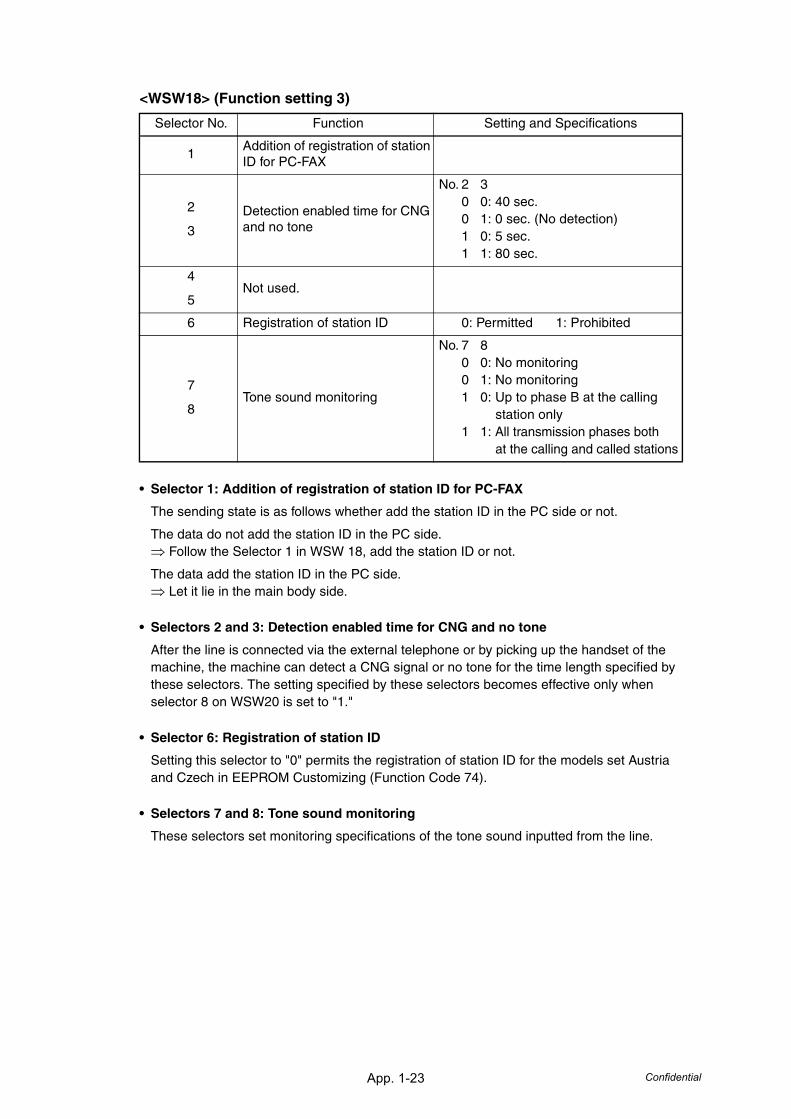
App. 1-23 Confidential
<WSW18> (Function setting 3)
• Selector 1: Addition of registration of station ID for PC-FAX
The sending state is as follows whether add the station ID in the PC side or not.
The data do not add the station ID in the PC side.⇒ Follow the Selector 1 in WSW 18, add the station ID or not.
The data add the station ID in the PC side.⇒ Let it lie in the main body side.
• Selectors 2 and 3: Detection enabled time for CNG and no tone
After the line is connected via the external telephone or by picking up the handset of the machine, the machine can detect a CNG signal or no tone for the time length specified by these selectors. The setting specified by these selectors becomes effective only when selector 8 on WSW20 is set to "1."
• Selector 6: Registration of station ID
Setting this selector to "0" permits the registration of station ID for the models set Austria and Czech in EEPROM Customizing (Function Code 74).
• Selectors 7 and 8: Tone sound monitoring
These selectors set monitoring specifications of the tone sound inputted from the line.
Selector No. Function Setting and Specifications
1Addition of registration of station ID for PC-FAX
2
3
Detection enabled time for CNG and no tone
No. 2 30 0: 40 sec.0 1: 0 sec. (No detection)1 0: 5 sec.1 1: 80 sec.
4
5Not used.
6 Registration of station ID 0: Permitted 1: Prohibited
7
8Tone sound monitoring
No. 7 80 0: No monitoring0 1: No monitoring1 0: Up to phase B at the calling
station only1 1: All transmission phases both
at the calling and called stations
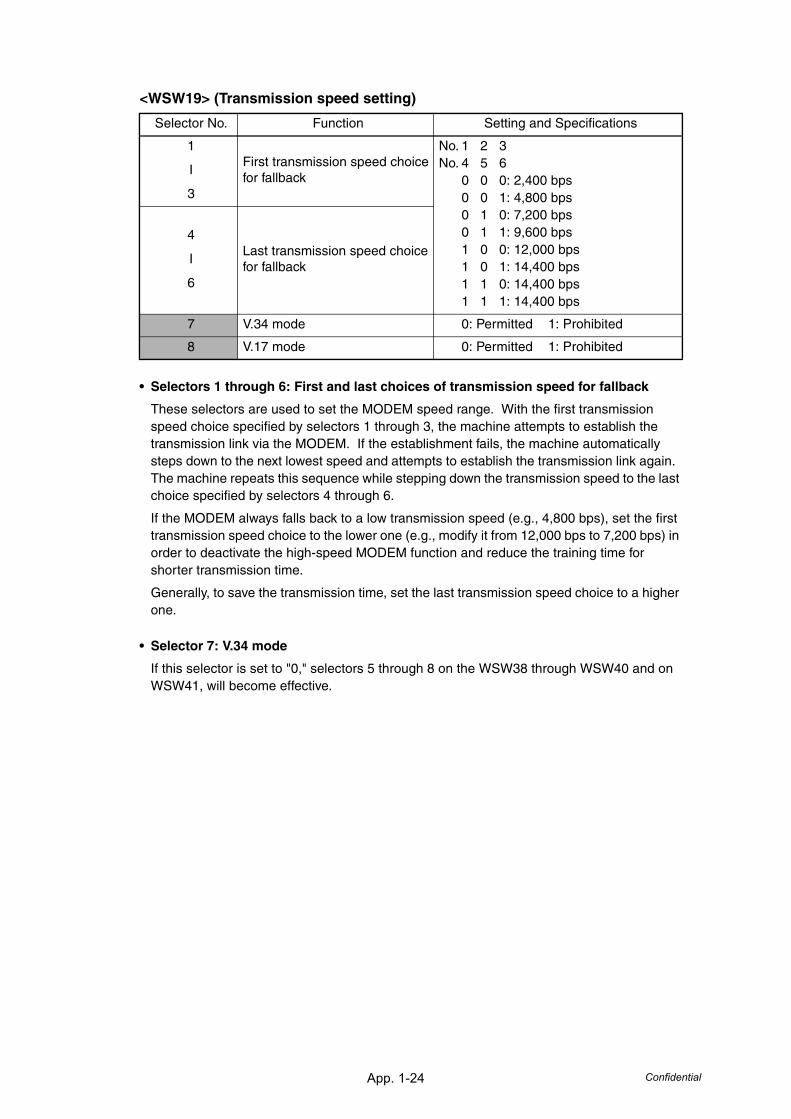
App. 1-24 Confidential
<WSW19> (Transmission speed setting)
• Selectors 1 through 6: First and last choices of transmission speed for fallback
These selectors are used to set the MODEM speed range. With the first transmission speed choice specified by selectors 1 through 3, the machine attempts to establish the transmission link via the MODEM. If the establishment fails, the machine automatically steps down to the next lowest speed and attempts to establish the transmission link again. The machine repeats this sequence while stepping down the transmission speed to the last choice specified by selectors 4 through 6.
If the MODEM always falls back to a low transmission speed (e.g., 4,800 bps), set the first transmission speed choice to the lower one (e.g., modify it from 12,000 bps to 7,200 bps) in order to deactivate the high-speed MODEM function and reduce the training time for shorter transmission time.
Generally, to save the transmission time, set the last transmission speed choice to a higher one.
• Selector 7: V.34 mode
If this selector is set to "0," selectors 5 through 8 on the WSW38 through WSW40 and on WSW41, will become effective.
Selector No. Function Setting and Specifications
1
I
3
First transmission speed choice for fallback
No. 1 2 3No. 4 5 6
0 0 0: 2,400 bps0 0 1: 4,800 bps0 1 0: 7,200 bps0 1 1: 9,600 bps1 0 0: 12,000 bps1 0 1: 14,400 bps1 1 0: 14,400 bps1 1 1: 14,400 bps
4
I
6
Last transmission speed choice for fallback
7 V.34 mode 0: Permitted 1: Prohibited
8 V.17 mode 0: Permitted 1: Prohibited
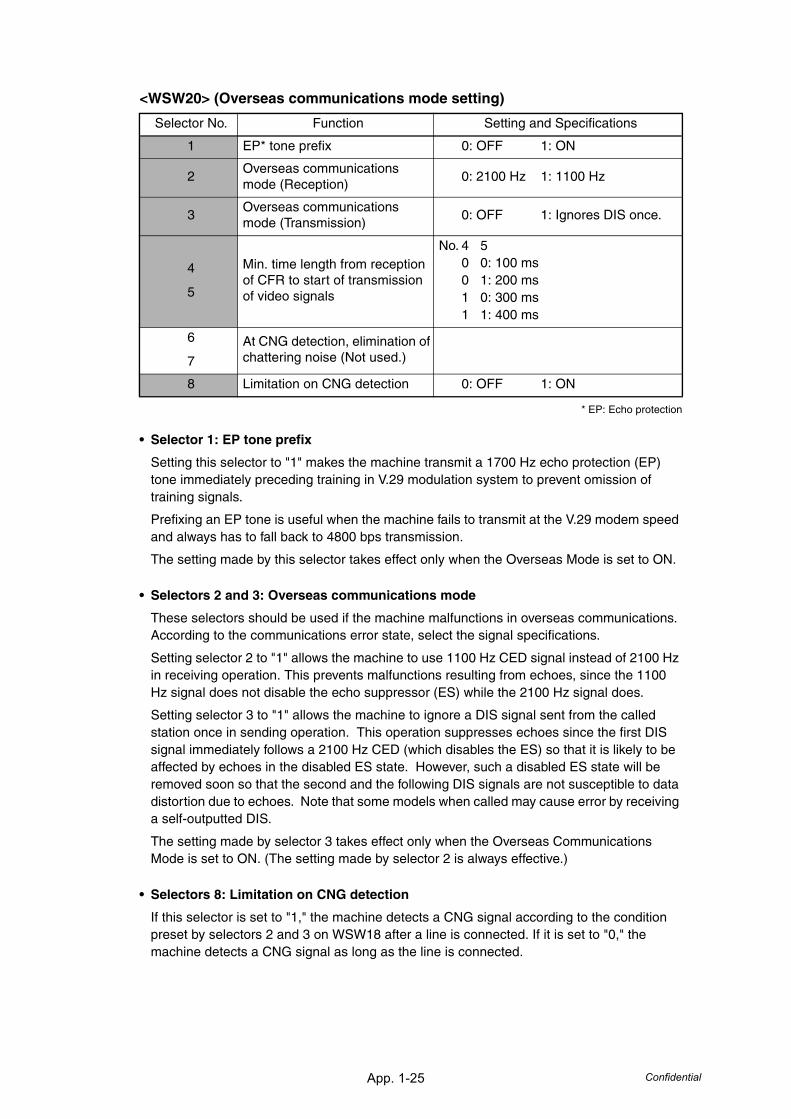
App. 1-25 Confidential
<WSW20> (Overseas communications mode setting)
* EP: Echo protection
• Selector 1: EP tone prefix
Setting this selector to "1" makes the machine transmit a 1700 Hz echo protection (EP) tone immediately preceding training in V.29 modulation system to prevent omission of training signals.
Prefixing an EP tone is useful when the machine fails to transmit at the V.29 modem speed and always has to fall back to 4800 bps transmission.
The setting made by this selector takes effect only when the Overseas Mode is set to ON.
• Selectors 2 and 3: Overseas communications mode
These selectors should be used if the machine malfunctions in overseas communications. According to the communications error state, select the signal specifications.
Setting selector 2 to "1" allows the machine to use 1100 Hz CED signal instead of 2100 Hz in receiving operation. This prevents malfunctions resulting from echoes, since the 1100 Hz signal does not disable the echo suppressor (ES) while the 2100 Hz signal does.
Setting selector 3 to "1" allows the machine to ignore a DIS signal sent from the called station once in sending operation. This operation suppresses echoes since the first DIS signal immediately follows a 2100 Hz CED (which disables the ES) so that it is likely to be affected by echoes in the disabled ES state. However, such a disabled ES state will be removed soon so that the second and the following DIS signals are not susceptible to data distortion due to echoes. Note that some models when called may cause error by receiving a self-outputted DIS.
The setting made by selector 3 takes effect only when the Overseas Communications Mode is set to ON. (The setting made by selector 2 is always effective.)
• Selectors 8: Limitation on CNG detection
If this selector is set to "1," the machine detects a CNG signal according to the condition preset by selectors 2 and 3 on WSW18 after a line is connected. If it is set to "0," the machine detects a CNG signal as long as the line is connected.
Selector No. Function Setting and Specifications
1 EP* tone prefix 0: OFF 1: ON
2Overseas communications mode (Reception)
0: 2100 Hz 1: 1100 Hz
3Overseas communications mode (Transmission)
0: OFF 1: Ignores DIS once.
4
5
Min. time length from reception of CFR to start of transmission of video signals
No. 4 50 0: 100 ms0 1: 200 ms1 0: 300 ms1 1: 400 ms
6
7
At CNG detection, elimination of chattering noise (Not used.)
8 Limitation on CNG detection 0: OFF 1: ON
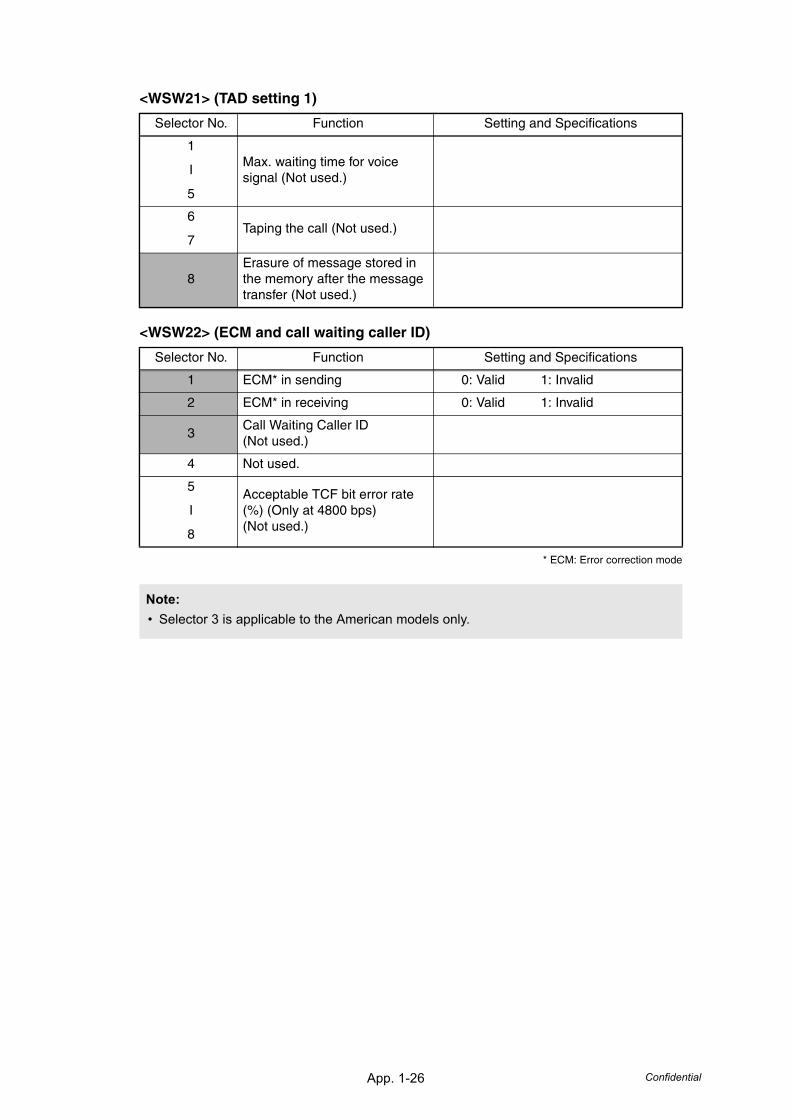
App. 1-26 Confidential
<WSW21> (TAD setting 1)
<WSW22> (ECM and call waiting caller ID)
* ECM: Error correction mode
Selector No. Function Setting and Specifications
1
I
5
Max. waiting time for voice signal (Not used.)
6
7Taping the call (Not used.)
8Erasure of message stored in the memory after the message transfer (Not used.)
Selector No. Function Setting and Specifications
1 ECM* in sending 0: Valid 1: Invalid
2 ECM* in receiving 0: Valid 1: Invalid
3Call Waiting Caller ID(Not used.)
4 Not used.
5
I
8
Acceptable TCF bit error rate (%) (Only at 4800 bps)(Not used.)
Note:• Selector 3 is applicable to the American models only.
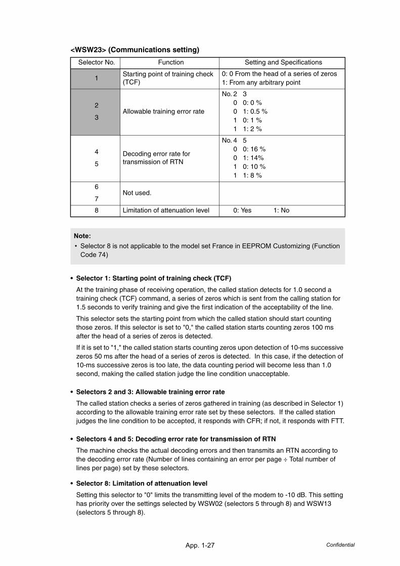
App. 1-27 Confidential
<WSW23> (Communications setting)
• Selector 1: Starting point of training check (TCF)
At the training phase of receiving operation, the called station detects for 1.0 second a training check (TCF) command, a series of zeros which is sent from the calling station for 1.5 seconds to verify training and give the first indication of the acceptability of the line.
This selector sets the starting point from which the called station should start counting those zeros. If this selector is set to "0," the called station starts counting zeros 100 ms after the head of a series of zeros is detected.
If it is set to "1," the called station starts counting zeros upon detection of 10-ms successive zeros 50 ms after the head of a series of zeros is detected. In this case, if the detection of 10-ms successive zeros is too late, the data counting period will become less than 1.0 second, making the called station judge the line condition unacceptable.
• Selectors 2 and 3: Allowable training error rate
The called station checks a series of zeros gathered in training (as described in Selector 1) according to the allowable training error rate set by these selectors. If the called station judges the line condition to be accepted, it responds with CFR; if not, it responds with FTT.
• Selectors 4 and 5: Decoding error rate for transmission of RTN
The machine checks the actual decoding errors and then transmits an RTN according to the decoding error rate (Number of lines containing an error per page ÷ Total number of lines per page) set by these selectors.
• Selector 8: Limitation of attenuation level
Setting this selector to "0" limits the transmitting level of the modem to -10 dB. This setting has priority over the settings selected by WSW02 (selectors 5 through 8) and WSW13 (selectors 5 through 8).
Selector No. Function Setting and Specifications
1Starting point of training check (TCF)
0: 0 From the head of a series of zeros1: From any arbitrary point
2
3Allowable training error rate
No. 2 30 0: 0 %0 1: 0.5 %1 0: 1 %1 1: 2 %
4
5
Decoding error rate for transmission of RTN
No. 4 50 0: 16 %0 1: 14%1 0: 10 %1 1: 8 %
6
7Not used.
8 Limitation of attenuation level 0: Yes 1: No
Note:• Selector 8 is not applicable to the model set France in EEPROM Customizing (Function
Code 74)
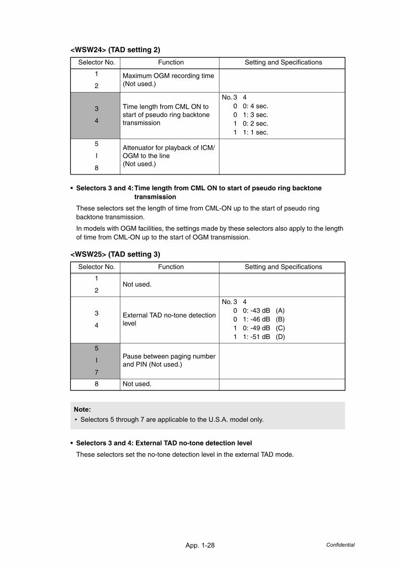
App. 1-28 Confidential
<WSW24> (TAD setting 2)
• Selectors 3 and 4:Time length from CML ON to start of pseudo ring backtone transmission
These selectors set the length of time from CML-ON up to the start of pseudo ring backtone transmission.
In models with OGM facilities, the settings made by these selectors also apply to the length of time from CML-ON up to the start of OGM transmission.
<WSW25> (TAD setting 3)
• Selectors 3 and 4: External TAD no-tone detection level
These selectors set the no-tone detection level in the external TAD mode.
Selector No. Function Setting and Specifications
1
2
Maximum OGM recording time(Not used.)
3
4
Time length from CML ON to start of pseudo ring backtone transmission
No. 3 40 0: 4 sec.0 1: 3 sec.1 0: 2 sec.1 1: 1 sec.
5
I
8
Attenuator for playback of ICM/OGM to the line(Not used.)
Selector No. Function Setting and Specifications
1
2Not used.
3
4
External TAD no-tone detection level
No. 3 40 0: -43 dB (A)0 1: -46 dB (B)1 0: -49 dB (C)1 1: -51 dB (D)
5
I
7
Pause between paging number and PIN (Not used.)
8 Not used.
Note:• Selectors 5 through 7 are applicable to the U.S.A. model only.
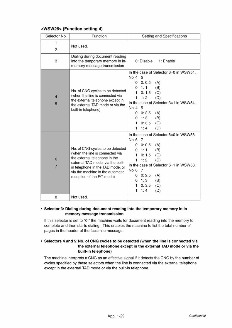
App. 1-29 Confidential
<WSW26> (Function setting 4)
• Selector 3: Dialing during document reading into the temporary memory in in-memory message transmission
If this selector is set to "0," the machine waits for document reading into the memory to complete and then starts dialing. This enables the machine to list the total number of pages in the header of the facsimile message.
• Selectors 4 and 5:No. of CNG cycles to be detected (when the line is connected via the external telephone except in the external TAD mode or via the built-in telephone)
The machine interprets a CNG as an effective signal if it detects the CNG by the number of cycles specified by these selectors when the line is connected via the external telephone except in the external TAD mode or via the built-in telephone.
Selector No. Function Setting and Specifications
1
2Not used.
3Dialing during document reading into the temporary memory in in-memory message transmission
0: Disable 1: Enable
4
5
No. of CNG cycles to be detected (when the line is connected via the external telephone except in the external TAD mode or via the built-in telephone)
In the case of Selector 3=0 in WSW54.No. 4 5
0 0: 0.5 (A)0 1: 1 (B)1 0: 1.5 (C)1 1: 2 (D)
In the case of Selector 3=1 in WSW54.No. 4 5
0 0: 2.5 (A)0 1: 3 (B)1 0: 3.5 (C)1 1: 4 (D)
6
7
No. of CNG cycles to be detected (when the line is connected via the external telephone in the external TAD mode, via the built-in telephone in the TAD mode, or via the machine in the automatic reception of the F/T mode)
In the case of Selector 6=0 in WSW58.No. 6 7
0 0: 0.5 (A)0 1: 1 (B)1 0: 1.5 (C)1 1: 2 (D)
In the case of Selector 6=1 in WSW58.No. 6 7
0 0: 2.5 (A)0 1: 3 (B)1 0: 3.5 (C)1 1: 4 (D)
8 Not used.
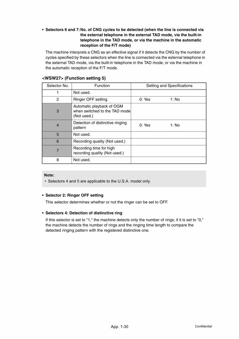
App. 1-30 Confidential
• Selectors 6 and 7:No. of CNG cycles to be detected (when the line is connected via the external telephone in the external TAD mode, via the built-in telephone in the TAD mode, or via the machine in the automatic reception of the F/T mode)
The machine interprets a CNG as an effective signal if it detects the CNG by the number of cycles specified by these selectors when the line is connected via the external telephone in the external TAD mode, via the built-in telephone in the TAD mode, or via the machine in the automatic reception of the F/T mode.
<WSW27> (Function setting 5)
• Selector 2: Ringer OFF setting
This selector determines whether or not the ringer can be set to OFF.
• Selectors 4: Detection of distinctive ring
If this selector is set to "1," the machine detects only the number of rings; if it is set to "0," the machine detects the number of rings and the ringing time length to compare the detected ringing pattern with the registered distinctive one.
Selector No. Function Setting and Specifications
1 Not used.
2 Ringer OFF setting 0: Yes 1: No
3Automatic playback of OGM when switched to the TAD mode(Not used.)
4Detection of distinctive ringing pattern
0: Yes 1: No
5 Not used.
6 Recording quality (Not used.)
7Recording time for high recording quality (Not used.)
8 Not used.
Note:• Selectors 4 and 5 are applicable to the U.S.A. model only.
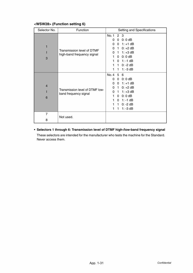
App. 1-31 Confidential
<WSW28> (Function setting 6)
• Selectors 1 through 6: Transmission level of DTMF high-/low-band frequency signal
These selectors are intended for the manufacturer who tests the machine for the Standard. Never access them.
Selector No. Function Setting and Specifications
1
I
3
Transmission level of DTMF high-band frequency signal
No. 1 2 30 0 0: 0 dB0 0 1: +1 dB0 1 0: +2 dB0 1 1: +3 dB1 0 0: 0 dB1 0 1: -1 dB1 1 0: -2 dB1 1 1: -3 dB
4
I
6
Transmission level of DTMF low-band frequency signal
No. 4 5 60 0 0: 0 dB0 0 1: +1 dB0 1 0: +2 dB0 1 1: +3 dB1 0 0: 0 dB1 0 1: -1 dB1 1 0: -2 dB1 1 1: -3 dB
7
8Not used.
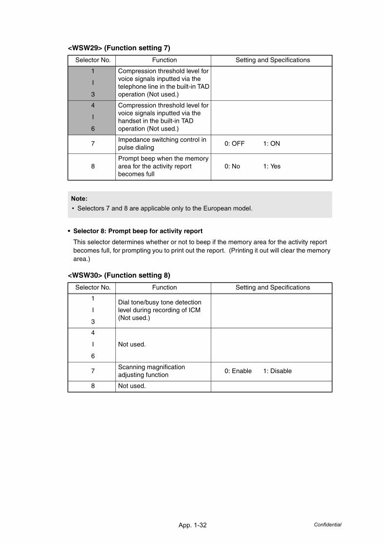
App. 1-32 Confidential
<WSW29> (Function setting 7)
• Selector 8: Prompt beep for activity report
This selector determines whether or not to beep if the memory area for the activity report becomes full, for prompting you to print out the report. (Printing it out will clear the memory area.)
<WSW30> (Function setting 8)
Selector No. Function Setting and Specifications
1
I
3
Compression threshold level for voice signals inputted via the telephone line in the built-in TAD operation (Not used.)
4
I
6
Compression threshold level for voice signals inputted via the handset in the built-in TAD operation (Not used.)
7Impedance switching control in pulse dialing
0: OFF 1: ON
8Prompt beep when the memory area for the activity report becomes full
0: No 1: Yes
Note:• Selectors 7 and 8 are applicable only to the European model.
Selector No. Function Setting and Specifications
1
I
3
Dial tone/busy tone detection level during recording of ICM(Not used.)
4
I
6
Not used.
7Scanning magnification adjusting function
0: Enable 1: Disable
8 Not used.
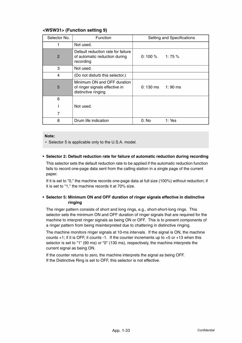
App. 1-33 Confidential
<WSW31> (Function setting 9)
• Selector 2: Default reduction rate for failure of automatic reduction during recording
This selector sets the default reduction rate to be applied if the automatic reduction function fails to record one-page data sent from the calling station in a single page of the current paper.
If it is set to "0," the machine records one-page data at full size (100%) without reduction; if it is set to "1," the machine records it at 70% size.
• Selector 5: Minimum ON and OFF duration of ringer signals effective in distinctive ringing
The ringer pattern consists of short and long rings, e.g., short-short-long rings. This selector sets the minimum ON and OFF duration of ringer signals that are required for the machine to interpret ringer signals as being ON or OFF. This is to prevent components of a ringer pattern from being misinterpreted due to chattering in distinctive ringing.
The machine monitors ringer signals at 10-ms intervals. If the signal is ON, the machine counts +1; if it is OFF, it counts -1. If the counter increments up to +5 or +13 when this selector is set to "1" (90 ms) or "0" (130 ms), respectively, the machine interprets the current signal as being ON.
If the counter returns to zero, the machine interprets the signal as being OFF.If the Distinctive Ring is set to OFF, this selector is not effective.
Selector No. Function Setting and Specifications
1 Not used.
2Default reduction rate for failure of automatic reduction during recording
0: 100 % 1: 75 %
3 Not used.
4 (Do not disturb this selector.)
5Minimum ON and OFF duration of ringer signals effective in distinctive ringing
0: 130 ms 1: 90 ms
6
I
7
Not used.
8 Drum life indication 0: No 1: Yes
Note:• Selector 5 is applicable only to the U.S.A. model.
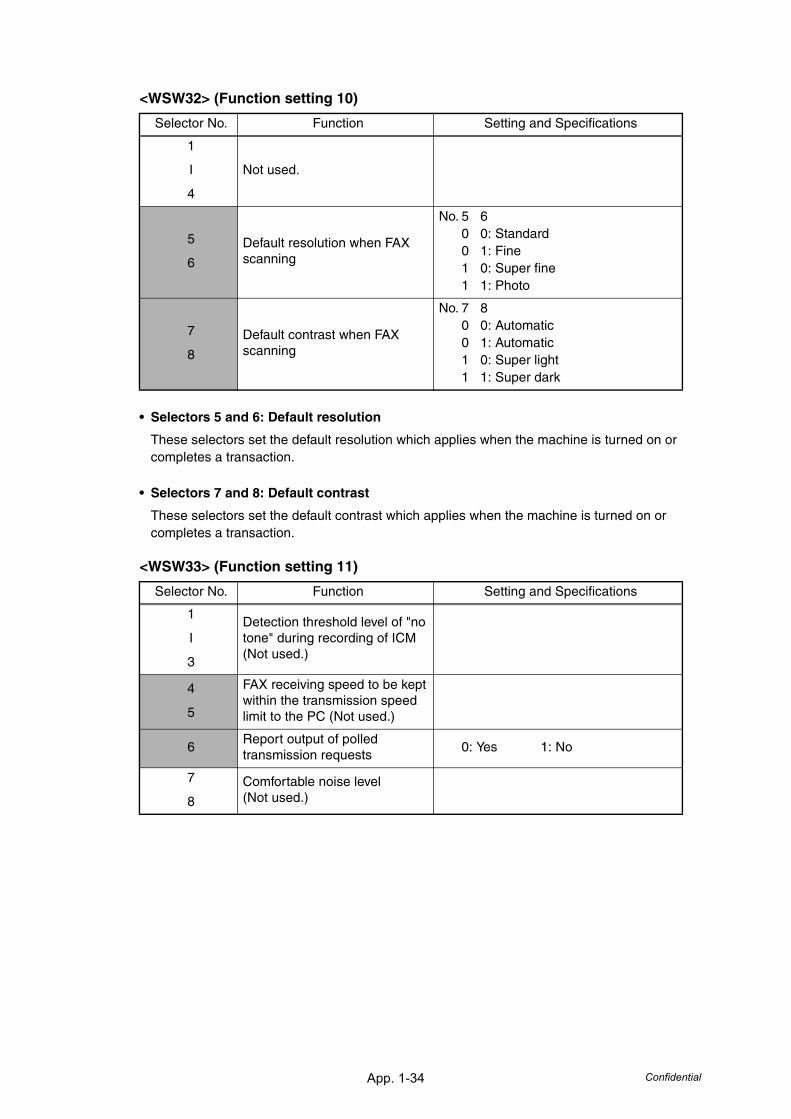
App. 1-34 Confidential
<WSW32> (Function setting 10)
• Selectors 5 and 6: Default resolution
These selectors set the default resolution which applies when the machine is turned on or completes a transaction.
• Selectors 7 and 8: Default contrast
These selectors set the default contrast which applies when the machine is turned on or completes a transaction.
<WSW33> (Function setting 11)
Selector No. Function Setting and Specifications
1
I
4
Not used.
5
6
Default resolution when FAX scanning
No. 5 60 0: Standard0 1: Fine1 0: Super fine1 1: Photo
7
8
Default contrast when FAX scanning
No. 7 80 0: Automatic0 1: Automatic1 0: Super light1 1: Super dark
Selector No. Function Setting and Specifications
1
I
3
Detection threshold level of "no tone" during recording of ICM(Not used.)
4
5
FAX receiving speed to be kept within the transmission speed limit to the PC (Not used.)
6Report output of polled transmission requests
0: Yes 1: No
7
8
Comfortable noise level(Not used.)
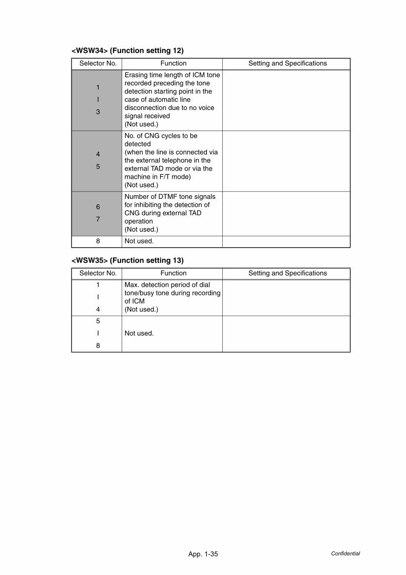
App. 1-35 Confidential
<WSW34> (Function setting 12)
<WSW35> (Function setting 13)
Selector No. Function Setting and Specifications
1
I
3
Erasing time length of ICM tone recorded preceding the tone detection starting point in the case of automatic line disconnection due to no voice signal received (Not used.)
4
5
No. of CNG cycles to be detected (when the line is connected via the external telephone in the external TAD mode or via the machine in F/T mode)(Not used.)
6
7
Number of DTMF tone signals for inhibiting the detection of CNG during external TAD operation(Not used.)
8 Not used.
Selector No. Function Setting and Specifications
1
I
4
Max. detection period of dial tone/busy tone during recording of ICM(Not used.)
5
I
8
Not used.
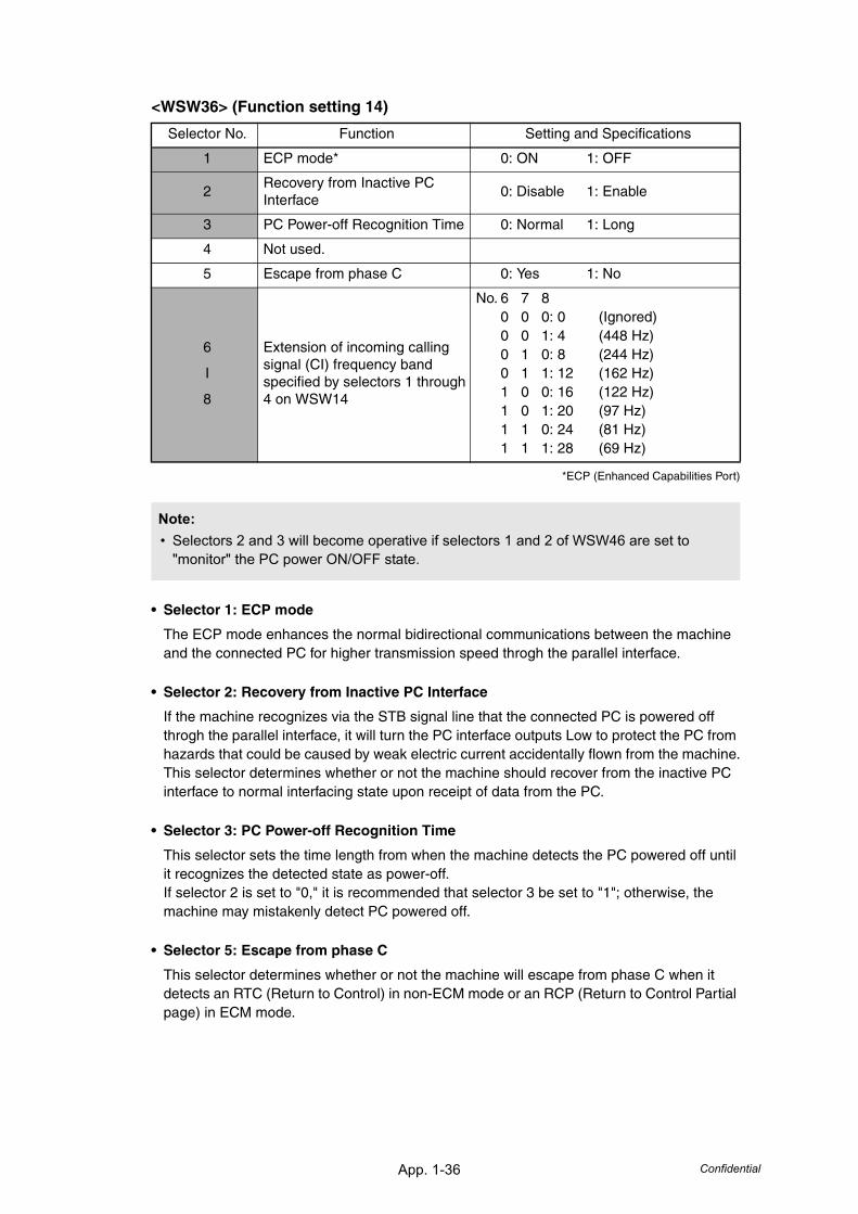
App. 1-36 Confidential
<WSW36> (Function setting 14)
*ECP (Enhanced Capabilities Port)
• Selector 1: ECP mode
The ECP mode enhances the normal bidirectional communications between the machine and the connected PC for higher transmission speed throgh the parallel interface.
• Selector 2: Recovery from Inactive PC Interface
If the machine recognizes via the STB signal line that the connected PC is powered off throgh the parallel interface, it will turn the PC interface outputs Low to protect the PC from hazards that could be caused by weak electric current accidentally flown from the machine.This selector determines whether or not the machine should recover from the inactive PC interface to normal interfacing state upon receipt of data from the PC.
• Selector 3: PC Power-off Recognition Time
This selector sets the time length from when the machine detects the PC powered off until it recognizes the detected state as power-off.If selector 2 is set to "0," it is recommended that selector 3 be set to "1"; otherwise, the machine may mistakenly detect PC powered off.
• Selector 5: Escape from phase C
This selector determines whether or not the machine will escape from phase C when it detects an RTC (Return to Control) in non-ECM mode or an RCP (Return to Control Partial page) in ECM mode.
Selector No. Function Setting and Specifications
1 ECP mode* 0: ON 1: OFF
2Recovery from Inactive PC Interface
0: Disable 1: Enable
3 PC Power-off Recognition Time 0: Normal 1: Long
4 Not used.
5 Escape from phase C 0: Yes 1: No
6
I
8
Extension of incoming calling signal (CI) frequency band specified by selectors 1 through 4 on WSW14
No. 6 7 80 0 0: 0 (Ignored)0 0 1: 4 (448 Hz)0 1 0: 8 (244 Hz)0 1 1: 12 (162 Hz)1 0 0: 16 (122 Hz)1 0 1: 20 (97 Hz)1 1 0: 24 (81 Hz)1 1 1: 28 (69 Hz)
Note:• Selectors 2 and 3 will become operative if selectors 1 and 2 of WSW46 are set to
"monitor" the PC power ON/OFF state.
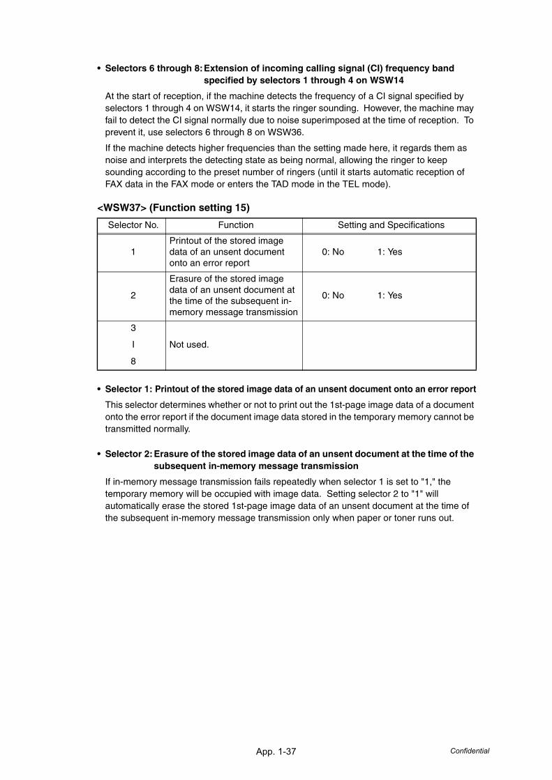
App. 1-37 Confidential
• Selectors 6 through 8:Extension of incoming calling signal (CI) frequency band specified by selectors 1 through 4 on WSW14
At the start of reception, if the machine detects the frequency of a CI signal specified by selectors 1 through 4 on WSW14, it starts the ringer sounding. However, the machine may fail to detect the CI signal normally due to noise superimposed at the time of reception. To prevent it, use selectors 6 through 8 on WSW36.
If the machine detects higher frequencies than the setting made here, it regards them as noise and interprets the detecting state as being normal, allowing the ringer to keep sounding according to the preset number of ringers (until it starts automatic reception of FAX data in the FAX mode or enters the TAD mode in the TEL mode).
<WSW37> (Function setting 15)
• Selector 1: Printout of the stored image data of an unsent document onto an error report
This selector determines whether or not to print out the 1st-page image data of a document onto the error report if the document image data stored in the temporary memory cannot be transmitted normally.
• Selector 2:Erasure of the stored image data of an unsent document at the time of the subsequent in-memory message transmission
If in-memory message transmission fails repeatedly when selector 1 is set to "1," the temporary memory will be occupied with image data. Setting selector 2 to "1" will automatically erase the stored 1st-page image data of an unsent document at the time of the subsequent in-memory message transmission only when paper or toner runs out.
Selector No. Function Setting and Specifications
1Printout of the stored image data of an unsent document onto an error report
0: No 1: Yes
2
Erasure of the stored image data of an unsent document at the time of the subsequent in-memory message transmission
0: No 1: Yes
3
I
8
Not used.
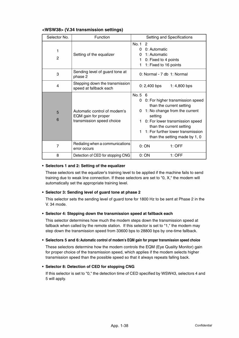
App. 1-38 Confidential
<WSW38> (V.34 transmission settings)
• Selectors 1 and 2: Setting of the equalizer
These selectors set the equalizer's training level to be applied if the machine fails to send training due to weak line connection. If these selectors are set to "0, X," the modem will automatically set the appropriate training level.
• Selector 3: Sending level of guard tone at phase 2
This selector sets the sending level of guard tone for 1800 Hz to be sent at Phase 2 in the V. 34 mode.
• Selector 4: Stepping down the transmission speed at fallback each
This selector determines how much the modem steps down the transmission speed at fallback when called by the remote station. If this selector is set to "1," the modem may step down the transmission speed from 33600 bps to 28800 bps by one-time fallback.
• Selectors 5 and 6:Automatic control of modem's EQM gain for proper transmission speed choice
These selectors determine how the modem controls the EQM (Eye Quality Monitor) gain for proper choice of the transmission speed, which applies if the modem selects higher transmission speed than the possible speed so that it always repeats falling back.
• Selector 8: Detection of CED for stopping CNG
If this selector is set to "0," the detection time of CED specified by WSW43, selectors 4 and 5 will apply.
Selector No. Function Setting and Specifications
1
2Setting of the equalizer
No. 1 20 0: Automatic0 1: Automatic1 0: Fixed to 4 points1 1: Fixed to 16 points
3Sending level of guard tone at phase 2
0: Normal - 7 db 1: Normal
4Stepping down the transmission speed at fallback each
0: 2,400 bps 1: 4,800 bps
5
6
Automatic control of modem's EQM gain for proper transmission speed choice
No. 5 60 0: For higher transmission speed
than the current setting0 1: No change from the current
setting1 0: For lower transmission speed
than the current setting1 1: For further lower transmission
than the setting made by 1, 0
7Redialing when a communications error occurs
0: ON 1: OFF
8 Detection of CED for stopping CNG 0: ON 1: OFF
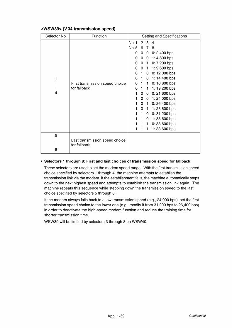
App. 1-39 Confidential
<WSW39> (V.34 transmission speed)
• Selectors 1 through 8: First and last choices of transmission speed for fallback
These selectors are used to set the modem speed range. With the first transmission speed choice specified by selectors 1 through 4, the machine attempts to establish the transmission link via the modem. If the establishment fails, the machine automatically steps down to the next highest speed and attempts to establish the transmission link again. The machine repeats this sequence while stepping down the transmission speed to the last choice specified by selectors 5 through 8.
If the modem always falls back to a low transmission speed (e.g., 24,000 bps), set the first transmission speed choice to the lower one (e.g., modify it from 31,200 bps to 26,400 bps) in order to deactivate the high-speed modem function and reduce the training time for shorter transmission time.
WSW39 will be limited by selectors 3 through 8 on WSW40.
Selector No. Function Setting and Specifications
1
I
4
First transmission speed choice for fallback
No. 1 2 3 4No. 5 6 7 8
0 0 0 0: 2,400 bps0 0 0 1: 4,800 bps0 0 1 0: 7,200 bps0 0 1 1: 9,600 bps0 1 0 0: 12,000 bps0 1 0 1: 14,400 bps0 1 1 0: 16,800 bps0 1 1 1: 19,200 bps1 0 0 0: 21,600 bps1 0 0 1: 24,000 bps1 0 1 0: 26,400 bps1 0 1 1: 28,800 bps1 1 0 0: 31,200 bps1 1 0 1: 33,600 bps1 1 1 0: 33,600 bps1 1 1 1: 33,600 bps
5
I
8
Last transmission speed choice for fallback
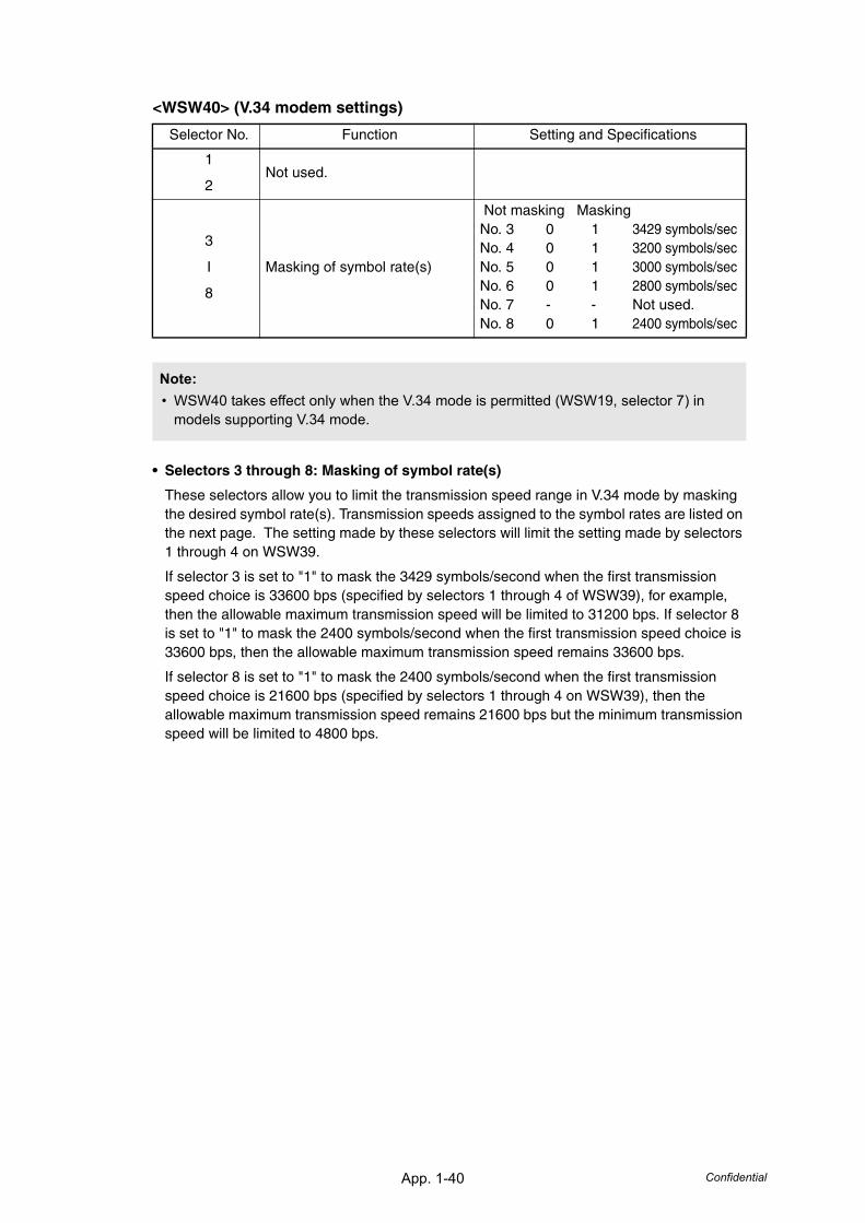
App. 1-40 Confidential
<WSW40> (V.34 modem settings)
• Selectors 3 through 8: Masking of symbol rate(s)
These selectors allow you to limit the transmission speed range in V.34 mode by masking the desired symbol rate(s). Transmission speeds assigned to the symbol rates are listed on the next page. The setting made by these selectors will limit the setting made by selectors 1 through 4 on WSW39.
If selector 3 is set to "1" to mask the 3429 symbols/second when the first transmission speed choice is 33600 bps (specified by selectors 1 through 4 of WSW39), for example, then the allowable maximum transmission speed will be limited to 31200 bps. If selector 8 is set to "1" to mask the 2400 symbols/second when the first transmission speed choice is 33600 bps, then the allowable maximum transmission speed remains 33600 bps.
If selector 8 is set to "1" to mask the 2400 symbols/second when the first transmission speed choice is 21600 bps (specified by selectors 1 through 4 on WSW39), then the allowable maximum transmission speed remains 21600 bps but the minimum transmission speed will be limited to 4800 bps.
Selector No. Function Setting and Specifications
1
2Not used.
3
I
8
Masking of symbol rate(s)
Not masking MaskingNo. 3 0 1 3429 symbols/secNo. 4 0 1 3200 symbols/secNo. 5 0 1 3000 symbols/secNo. 6 0 1 2800 symbols/secNo. 7 - - Not used.No. 8 0 1 2400 symbols/sec
Note:• WSW40 takes effect only when the V.34 mode is permitted (WSW19, selector 7) in
models supporting V.34 mode.
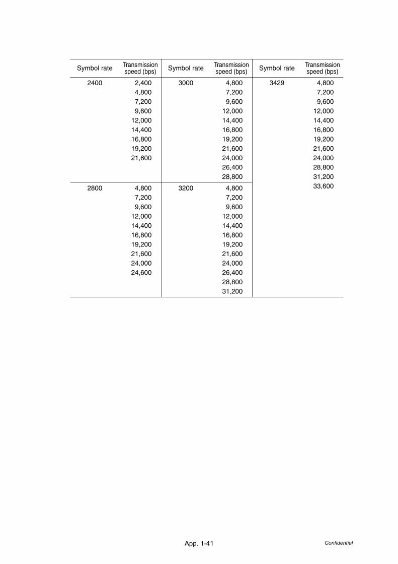
App. 1-41 Confidential
Symbol rate Transmission speed (bps) Symbol rate Transmission
speed (bps) Symbol rate Transmission speed (bps)
2400 2,4004,8007,2009,600
12,00014,40016,80019,20021,600
3000 4,8007,2009,600
12,00014,40016,80019,20021,60024,00026,40028,800
3429 4,8007,2009,600
12,00014,40016,80019,20021,60024,00028,80031,20033,6002800 4,800
7,2009,600
12,00014,40016,80019,20021,60024,00024,600
3200 4,8007,2009,600
12,00014,40016,80019,20021,60024,00026,40028,80031,200
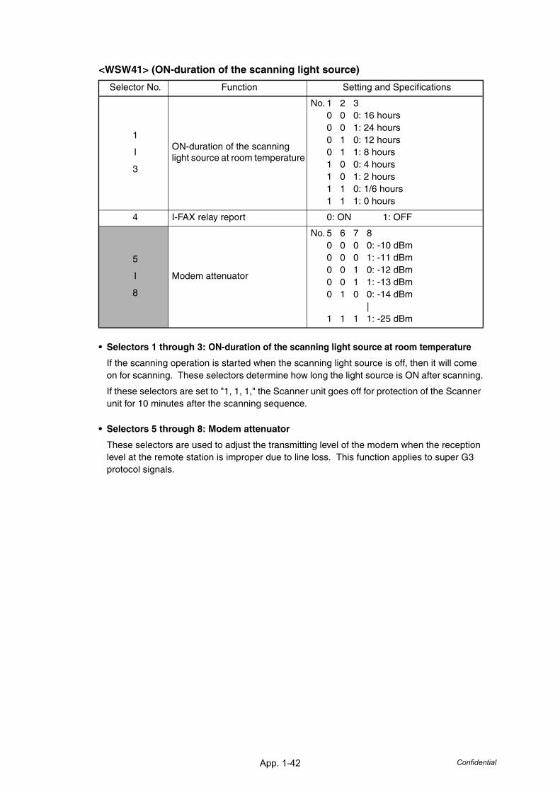
App. 1-42 Confidential
<WSW41> (ON-duration of the scanning light source)
• Selectors 1 through 3: ON-duration of the scanning light source at room temperature
If the scanning operation is started when the scanning light source is off, then it will come on for scanning. These selectors determine how long the light source is ON after scanning.
If these selectors are set to "1, 1, 1," the Scanner unit goes off for protection of the Scanner unit for 10 minutes after the scanning sequence.
• Selectors 5 through 8: Modem attenuator
These selectors are used to adjust the transmitting level of the modem when the reception level at the remote station is improper due to line loss. This function applies to super G3 protocol signals.
Selector No. Function Setting and Specifications
1
I
3
ON-duration of the scanning light source at room temperature
No. 1 2 30 0 0: 16 hours0 0 1: 24 hours0 1 0: 12 hours0 1 1: 8 hours1 0 0: 4 hours1 0 1: 2 hours1 1 0: 1/6 hours1 1 1: 0 hours
4 I-FAX relay report 0: ON 1: OFF
5
I
8
Modem attenuator
No. 5 6 7 80 0 0 0: -10 dBm0 0 0 1: -11 dBm0 0 1 0: -12 dBm0 0 1 1: -13 dBm0 1 0 0: -14 dBm
|1 1 1 1: -25 dBm
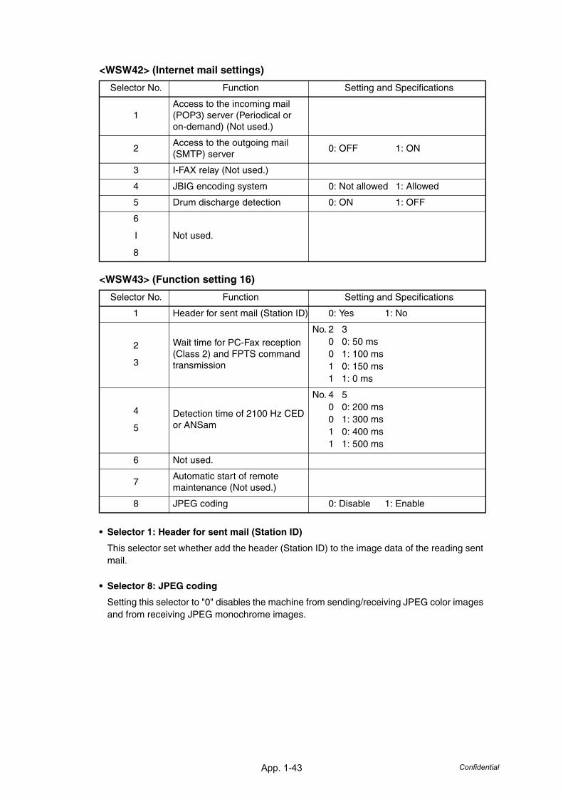
App. 1-43 Confidential
<WSW42> (Internet mail settings)
<WSW43> (Function setting 16)
• Selector 1: Header for sent mail (Station ID)
This selector set whether add the header (Station ID) to the image data of the reading sent mail.
• Selector 8: JPEG coding
Setting this selector to "0" disables the machine from sending/receiving JPEG color images and from receiving JPEG monochrome images.
Selector No. Function Setting and Specifications
1Access to the incoming mail (POP3) server (Periodical or on-demand) (Not used.)
2Access to the outgoing mail (SMTP) server
0: OFF 1: ON
3 I-FAX relay (Not used.)
4 JBIG encoding system 0: Not allowed 1: Allowed
5 Drum discharge detection 0: ON 1: OFF
6
I
8
Not used.
Selector No. Function Setting and Specifications
1 Header for sent mail (Station ID) 0: Yes 1: No
2
3
Wait time for PC-Fax reception (Class 2) and FPTS command transmission
No. 2 30 0: 50 ms0 1: 100 ms1 0: 150 ms1 1: 0 ms
4
5
Detection time of 2100 Hz CED or ANSam
No. 4 50 0: 200 ms0 1: 300 ms1 0: 400 ms1 1: 500 ms
6 Not used.
7Automatic start of remote maintenance (Not used.)
8 JPEG coding 0: Disable 1: Enable
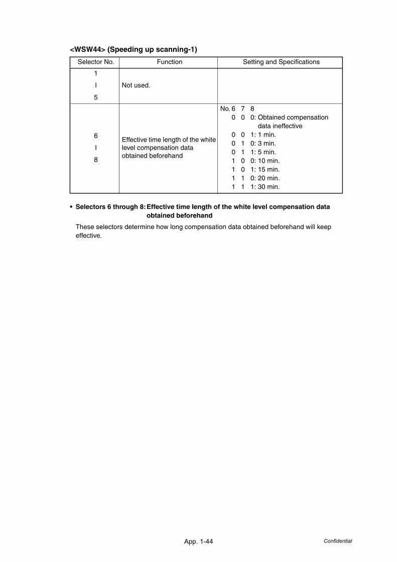
App. 1-44 Confidential
<WSW44> (Speeding up scanning-1)
• Selectors 6 through 8:Effective time length of the white level compensation data obtained beforehand
These selectors determine how long compensation data obtained beforehand will keep effective.
Selector No. Function Setting and Specifications
1
I
5
Not used.
6
I
8
Effective time length of the white level compensation data obtained beforehand
No. 6 7 80 0 0: Obtained compensation
data ineffective0 0 1: 1 min.0 1 0: 3 min.0 1 1: 5 min.1 0 0: 10 min.1 0 1: 15 min.1 1 0: 20 min.1 1 1: 30 min.
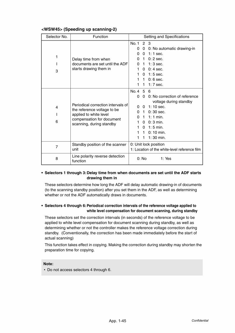
App. 1-45 Confidential
<WSW45> (Speeding up scanning-2)
• Selectors 1 through 3:Delay time from when documents are set until the ADF starts drawing them in
These selectors determine how long the ADF will delay automatic drawing-in of documents (to the scanning standby position) after you set them in the ADF, as well as determining whether or not the ADF automatically draws in documents.
• Selectors 4 through 6:Periodical correction intervals of the reference voltage applied to white level compensation for document scanning, during standby
These selectors set the correction intervals (in seconds) of the reference voltage to be applied to white level compensation for document scanning during standby, as well as determining whether or not the controller makes the reference voltage correction during standby. (Conventionally, the correction has been made immediately before the start of actual scanning)
This function takes effect in copying. Making the correction during standby may shorten the preparation time for copying.
Selector No. Function Setting and Specifications
1
I
3
Delay time from when documents are set until the ADF starts drawing them in
No. 1 2 30 0 0: No automatic drawing-in0 0 1: 1 sec.0 1 0: 2 sec.0 1 1: 3 sec.1 0 0: 4 sec.1 0 1: 5 sec.1 1 0: 6 sec.1 1 1: 7 sec.
4
I
6
Periodical correction intervals of the reference voltage to be applied to white level compensation for document scanning, during standby
No. 4 5 60 0 0: No correction of reference
voltage during standby0 0 1: 10 sec.0 1 0: 30 sec.0 1 1: 1 min.1 0 0: 3 min.1 0 1: 5 min.1 1 0: 10 min.1 1 1: 30 min.
7Standby position of the scanner unit
0: Unit lock position1: Location of the white-level reference film
8Line polarity reverse detection function
0: No 1: Yes
Note:• Do not access selectors 4 through 6.
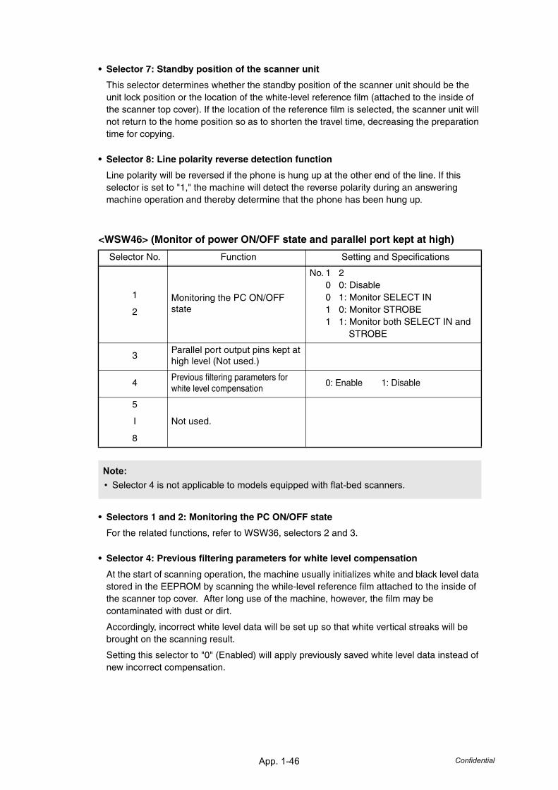
App. 1-46 Confidential
• Selector 7: Standby position of the scanner unit
This selector determines whether the standby position of the scanner unit should be the unit lock position or the location of the white-level reference film (attached to the inside of the scanner top cover). If the location of the reference film is selected, the scanner unit will not return to the home position so as to shorten the travel time, decreasing the preparation time for copying.
• Selector 8: Line polarity reverse detection function
Line polarity will be reversed if the phone is hung up at the other end of the line. If this selector is set to "1," the machine will detect the reverse polarity during an answering machine operation and thereby determine that the phone has been hung up.
<WSW46> (Monitor of power ON/OFF state and parallel port kept at high)
• Selectors 1 and 2: Monitoring the PC ON/OFF state
For the related functions, refer to WSW36, selectors 2 and 3.
• Selector 4: Previous filtering parameters for white level compensation
At the start of scanning operation, the machine usually initializes white and black level data stored in the EEPROM by scanning the while-level reference film attached to the inside of the scanner top cover. After long use of the machine, however, the film may be contaminated with dust or dirt.
Accordingly, incorrect white level data will be set up so that white vertical streaks will be brought on the scanning result.
Setting this selector to "0" (Enabled) will apply previously saved white level data instead of new incorrect compensation.
Selector No. Function Setting and Specifications
1
2
Monitoring the PC ON/OFF state
No. 1 20 0: Disable0 1: Monitor SELECT IN1 0: Monitor STROBE1 1: Monitor both SELECT IN and
STROBE
3Parallel port output pins kept at high level (Not used.)
4Previous filtering parameters for white level compensation
0: Enable 1: Disable
5
I
8
Not used.
Note:• Selector 4 is not applicable to models equipped with flat-bed scanners.
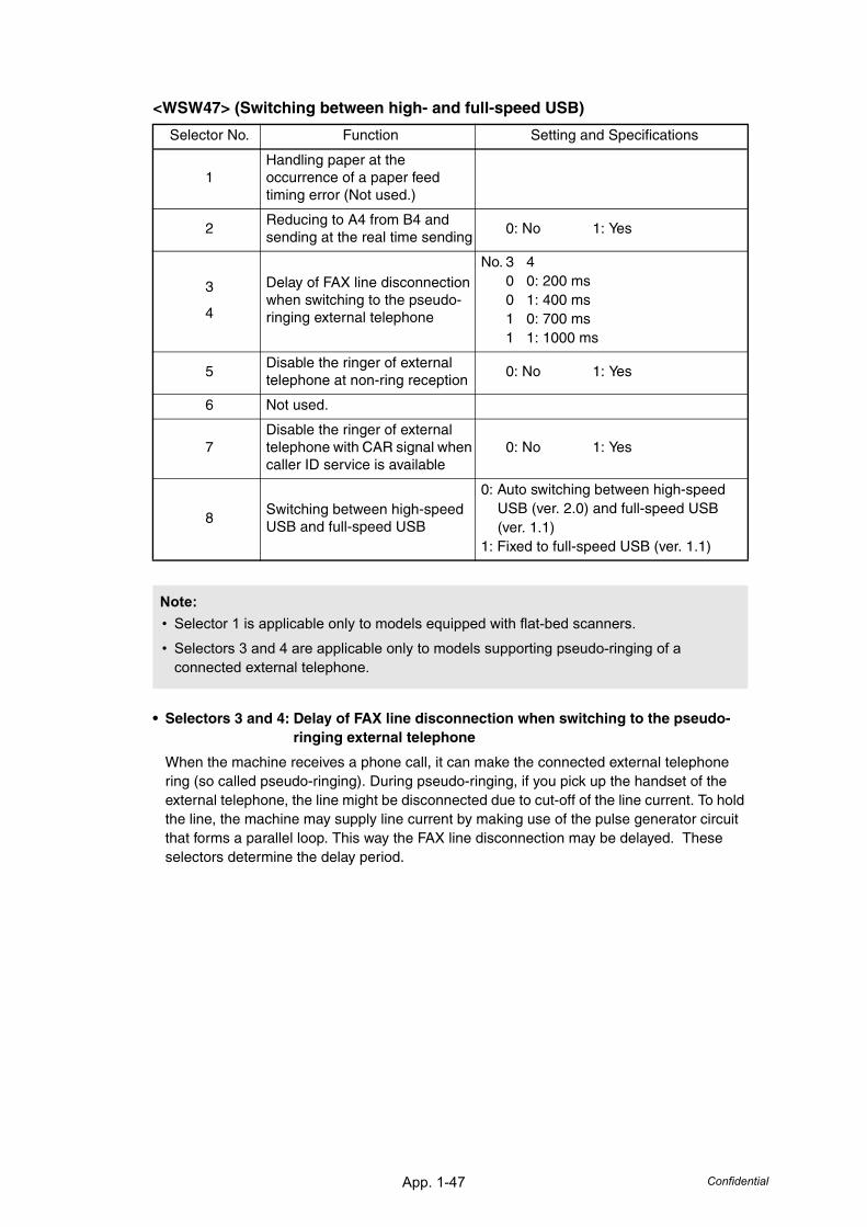
App. 1-47 Confidential
<WSW47> (Switching between high- and full-speed USB)
• Selectors 3 and 4: Delay of FAX line disconnection when switching to the pseudo-ringing external telephone
When the machine receives a phone call, it can make the connected external telephone ring (so called pseudo-ringing). During pseudo-ringing, if you pick up the handset of the external telephone, the line might be disconnected due to cut-off of the line current. To hold the line, the machine may supply line current by making use of the pulse generator circuit that forms a parallel loop. This way the FAX line disconnection may be delayed. These selectors determine the delay period.
Selector No. Function Setting and Specifications
1Handling paper at the occurrence of a paper feed timing error (Not used.)
2Reducing to A4 from B4 and sending at the real time sending
0: No 1: Yes
3
4
Delay of FAX line disconnection when switching to the pseudo-ringing external telephone
No. 3 40 0: 200 ms0 1: 400 ms1 0: 700 ms1 1: 1000 ms
5Disable the ringer of external telephone at non-ring reception
0: No 1: Yes
6 Not used.
7Disable the ringer of external telephone with CAR signal when caller ID service is available
0: No 1: Yes
8Switching between high-speed USB and full-speed USB
0: Auto switching between high-speed USB (ver. 2.0) and full-speed USB (ver. 1.1)
1: Fixed to full-speed USB (ver. 1.1)
Note:• Selector 1 is applicable only to models equipped with flat-bed scanners.
• Selectors 3 and 4 are applicable only to models supporting pseudo-ringing of a connected external telephone.
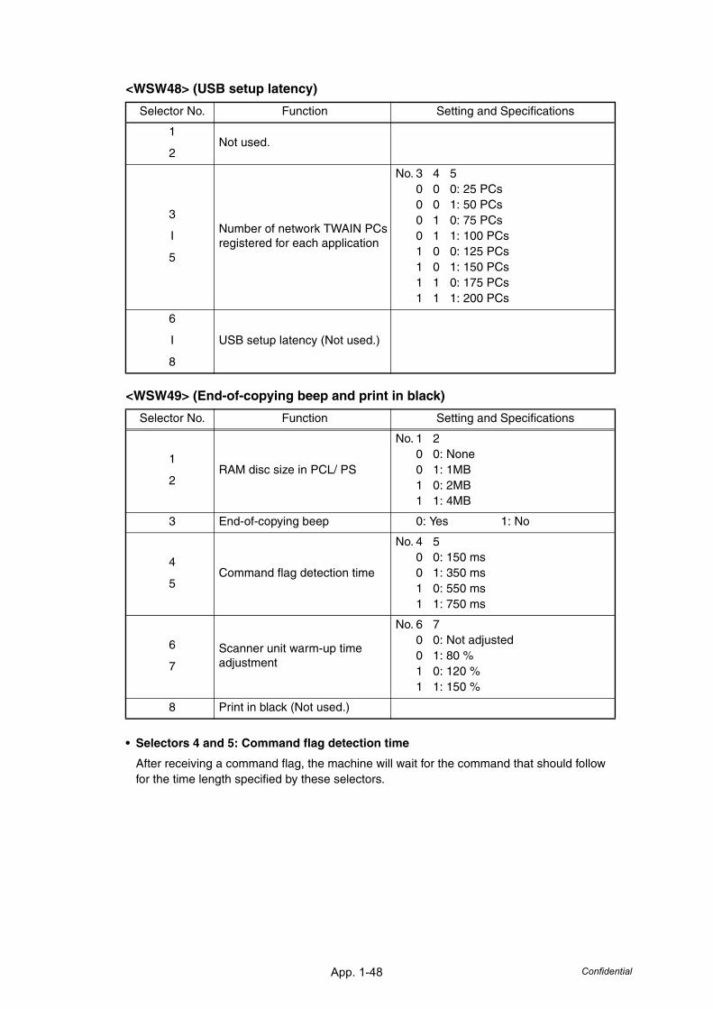
App. 1-48 Confidential
<WSW48> (USB setup latency)
<WSW49> (End-of-copying beep and print in black)
• Selectors 4 and 5: Command flag detection time
After receiving a command flag, the machine will wait for the command that should follow for the time length specified by these selectors.
Selector No. Function Setting and Specifications
1
2Not used.
3
I
5
Number of network TWAIN PCs registered for each application
No. 3 4 50 0 0: 25 PCs0 0 1: 50 PCs0 1 0: 75 PCs0 1 1: 100 PCs1 0 0: 125 PCs1 0 1: 150 PCs1 1 0: 175 PCs1 1 1: 200 PCs
6
I
8
USB setup latency (Not used.)
Selector No. Function Setting and Specifications
1
2RAM disc size in PCL/ PS
No. 1 20 0: None0 1: 1MB1 0: 2MB1 1: 4MB
3 End-of-copying beep 0: Yes 1: No
4
5Command flag detection time
No. 4 50 0: 150 ms0 1: 350 ms1 0: 550 ms1 1: 750 ms
6
7
Scanner unit warm-up time adjustment
No. 6 70 0: Not adjusted0 1: 80 %1 0: 120 %1 1: 150 %
8 Print in black (Not used.)
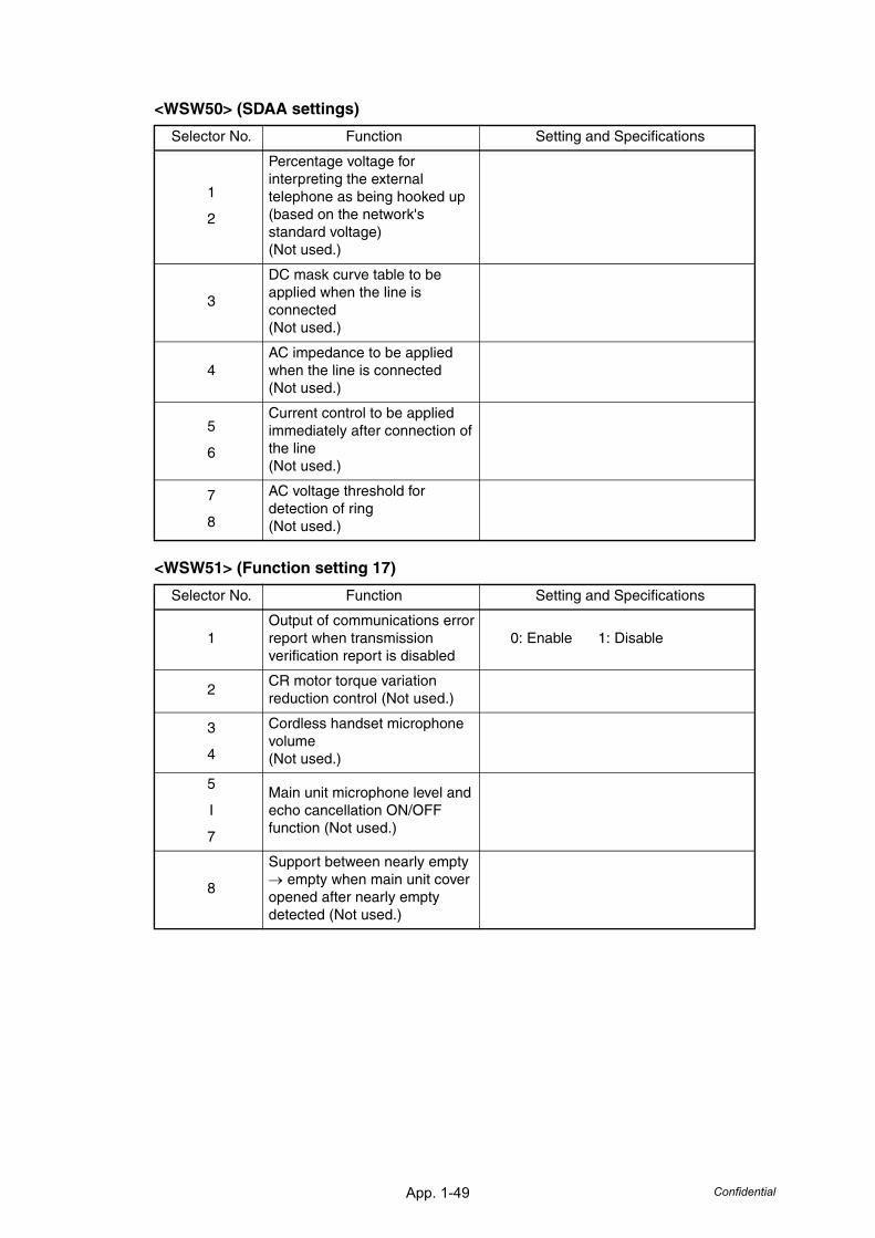
App. 1-49 Confidential
<WSW50> (SDAA settings)
<WSW51> (Function setting 17)
Selector No. Function Setting and Specifications
1
2
Percentage voltage for interpreting the external telephone as being hooked up(based on the network's standard voltage)(Not used.)
3
DC mask curve table to be applied when the line is connected(Not used.)
4AC impedance to be applied when the line is connected(Not used.)
5
6
Current control to be applied immediately after connection of the line(Not used.)
7
8
AC voltage threshold for detection of ring(Not used.)
Selector No. Function Setting and Specifications
1Output of communications error report when transmission verification report is disabled
0: Enable 1: Disable
2CR motor torque variation reduction control (Not used.)
3
4
Cordless handset microphone volume(Not used.)
5
I
7
Main unit microphone level and echo cancellation ON/OFF function (Not used.)
8
Support between nearly empty → empty when main unit cover opened after nearly empty detected (Not used.)
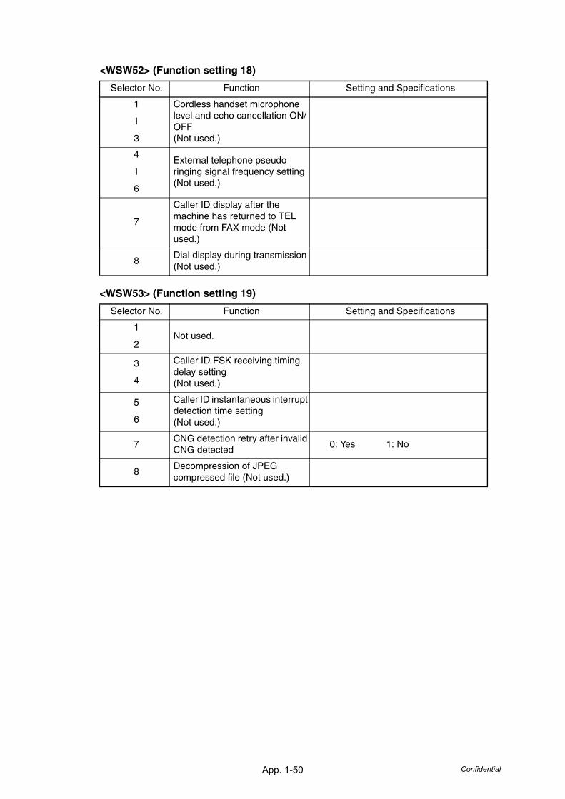
App. 1-50 Confidential
<WSW52> (Function setting 18)
<WSW53> (Function setting 19)
Selector No. Function Setting and Specifications
1
I
3
Cordless handset microphone level and echo cancellation ON/OFF(Not used.)
4
I
6
External telephone pseudo ringing signal frequency setting(Not used.)
7
Caller ID display after the machine has returned to TEL mode from FAX mode (Not used.)
8Dial display during transmission (Not used.)
Selector No. Function Setting and Specifications
1
2Not used.
3
4
Caller ID FSK receiving timing delay setting(Not used.)
5
6
Caller ID instantaneous interrupt detection time setting(Not used.)
7CNG detection retry after invalid CNG detected
0: Yes 1: No
8Decompression of JPEG compressed file (Not used.)
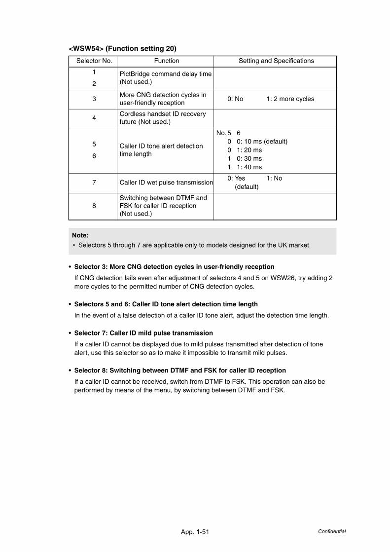
App. 1-51 Confidential
<WSW54> (Function setting 20)
• Selector 3: More CNG detection cycles in user-friendly reception
If CNG detection fails even after adjustment of selectors 4 and 5 on WSW26, try adding 2 more cycles to the permitted number of CNG detection cycles.
• Selectors 5 and 6: Caller ID tone alert detection time length
In the event of a false detection of a caller ID tone alert, adjust the detection time length.
• Selector 7: Caller ID mild pulse transmission
If a caller ID cannot be displayed due to mild pulses transmitted after detection of tone alert, use this selector so as to make it impossible to transmit mild pulses.
• Selector 8: Switching between DTMF and FSK for caller ID reception
If a caller ID cannot be received, switch from DTMF to FSK. This operation can also be performed by means of the menu, by switching between DTMF and FSK.
Selector No. Function Setting and Specifications
1
2
PictBridge command delay time(Not used.)
3More CNG detection cycles in user-friendly reception
0: No 1: 2 more cycles
4Cordless handset ID recovery future (Not used.)
5
6
Caller ID tone alert detection time length
No. 5 60 0: 10 ms (default)0 1: 20 ms1 0: 30 ms1 1: 40 ms
7 Caller ID wet pulse transmission0: Yes 1: No (default)
8Switching between DTMF and FSK for caller ID reception (Not used.)
Note:• Selectors 5 through 7 are applicable only to models designed for the UK market.
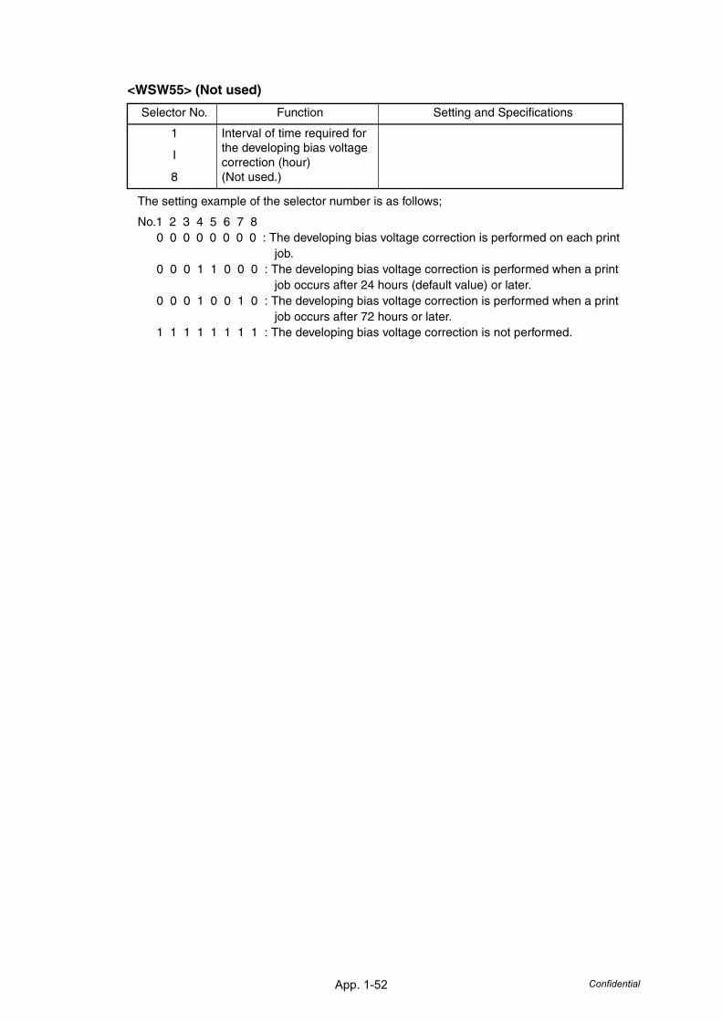
App. 1-52 Confidential
<WSW55> (Not used)
The setting example of the selector number is as follows;
No.1 2 3 4 5 6 7 80 0 0 0 0 0 0 0 : The developing bias voltage correction is performed on each print
job.0 0 0 1 1 0 0 0 : The developing bias voltage correction is performed when a print
job occurs after 24 hours (default value) or later.0 0 0 1 0 0 1 0 : The developing bias voltage correction is performed when a print
job occurs after 72 hours or later.1 1 1 1 1 1 1 1 : The developing bias voltage correction is not performed.
Selector No. Function Setting and Specifications
1
I
8
Interval of time required for the developing bias voltage correction (hour)(Not used.)
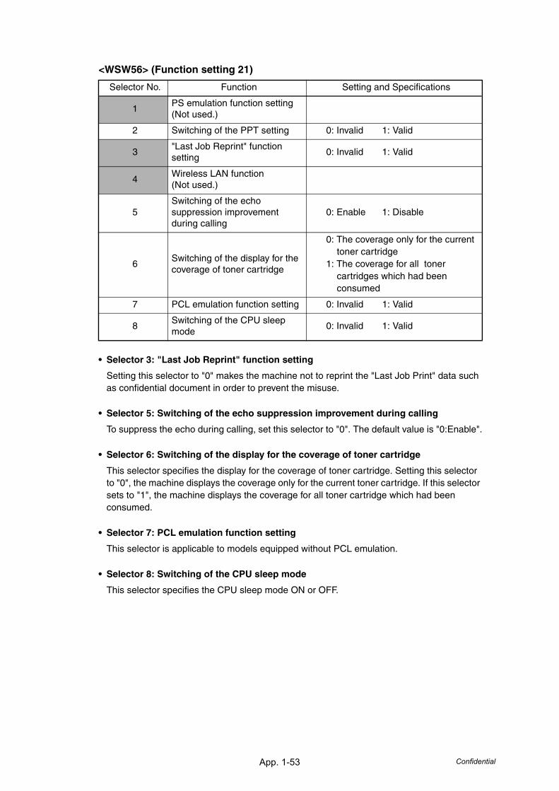
App. 1-53 Confidential
<WSW56> (Function setting 21)
• Selector 3: "Last Job Reprint" function setting
Setting this selector to "0" makes the machine not to reprint the "Last Job Print" data such as confidential document in order to prevent the misuse.
• Selector 5: Switching of the echo suppression improvement during calling
To suppress the echo during calling, set this selector to "0". The default value is "0:Enable".
• Selector 6: Switching of the display for the coverage of toner cartridge
This selector specifies the display for the coverage of toner cartridge. Setting this selector to "0", the machine displays the coverage only for the current toner cartridge. If this selector sets to "1", the machine displays the coverage for all toner cartridge which had been consumed.
• Selector 7: PCL emulation function setting
This selector is applicable to models equipped without PCL emulation.
• Selector 8: Switching of the CPU sleep mode
This selector specifies the CPU sleep mode ON or OFF.
Selector No. Function Setting and Specifications
1PS emulation function setting (Not used.)
2 Switching of the PPT setting 0: Invalid 1: Valid
3"Last Job Reprint" function setting
0: Invalid 1: Valid
4Wireless LAN function(Not used.)
5Switching of the echo suppression improvement during calling
0: Enable 1: Disable
6Switching of the display for the coverage of toner cartridge
0: The coverage only for the current toner cartridge
1: The coverage for all toner cartridges which had been consumed
7 PCL emulation function setting 0: Invalid 1: Valid
8Switching of the CPU sleep mode
0: Invalid 1: Valid
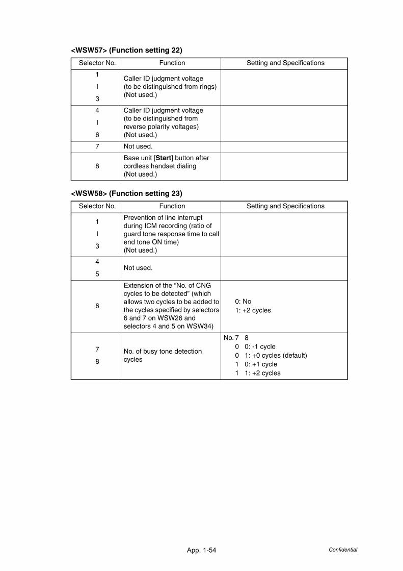
App. 1-54 Confidential
<WSW57> (Function setting 22)
<WSW58> (Function setting 23)
Selector No. Function Setting and Specifications
1
I
3
Caller ID judgment voltage(to be distinguished from rings)(Not used.)
4
I
6
Caller ID judgment voltage(to be distinguished from reverse polarity voltages)(Not used.)
7 Not used.
8Base unit [Start] button after cordless handset dialing(Not used.)
Selector No. Function Setting and Specifications
1
I
3
Prevention of line interrupt during ICM recording (ratio of guard tone response time to call end tone ON time)(Not used.)
4
5Not used.
6
Extension of the “No. of CNG cycles to be detected” (which allows two cycles to be added to the cycles specified by selectors 6 and 7 on WSW26 and selectors 4 and 5 on WSW34)
0: No1: +2 cycles
7
8
No. of busy tone detection cycles
No. 7 80 0: -1 cycle0 1: +0 cycles (default)1 0: +1 cycle1 1: +2 cycles
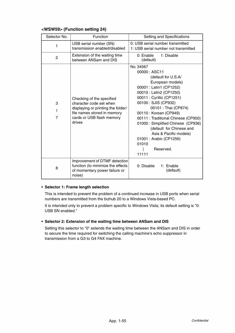
App. 1-55 Confidential
<WSW59> (Function setting 24)
• Selector 1: Frame length selection
This is intended to prevent the problem of a continued increase in USB ports when serial numbers are transmitted from the bizhub 20 to a Windows Vista-based PC.
It is intended only to prevent a problem specific to Windows Vista; its default setting is "0: USB SN enabled."
• Selector 2: Extension of the waiting time between ANSam and DIS
Setting this selector to "0" extends the waiting time between the ANSam and DIS in order to secure the time required for switching the calling machine's echo suppressor in transmission from a G3 to G4 FAX machine.
Selector No. Function Setting and Specifications
1USB serial number (SN) transmission enabled/disabled
0: USB serial number transmitted1: USB serial number not transmitted
2Extension of the waiting time between ANSam and DIS
0: Enable 1: Disable (default)
3
I
7
Checking of the specified character code set when displaying or printing the folder/file names stored in memory cards or USB flash memory drives
No. 3456700000 : ASC11
(default for U.S.A/ European models)
00001 : Latin1 (CP1252)00010 : Latin2 (CP1250)00011 : Cyrillic (CP1251)00100 : SJIS (CP932)
00101 : Thai (CP874)00110 : Korean (CP949)00111 : Traditional Chinese (CP950)01000 : Simplified Chinese (CP936)
(default for Chinese and Asia & Pacific models)
01001 : Arabic (CP1256)01010
| Reserved.11111
8
Improvement of DTMF detection function (to minimize the effects of momentary power failure or noise)
0: Disable 1: Enable (default)
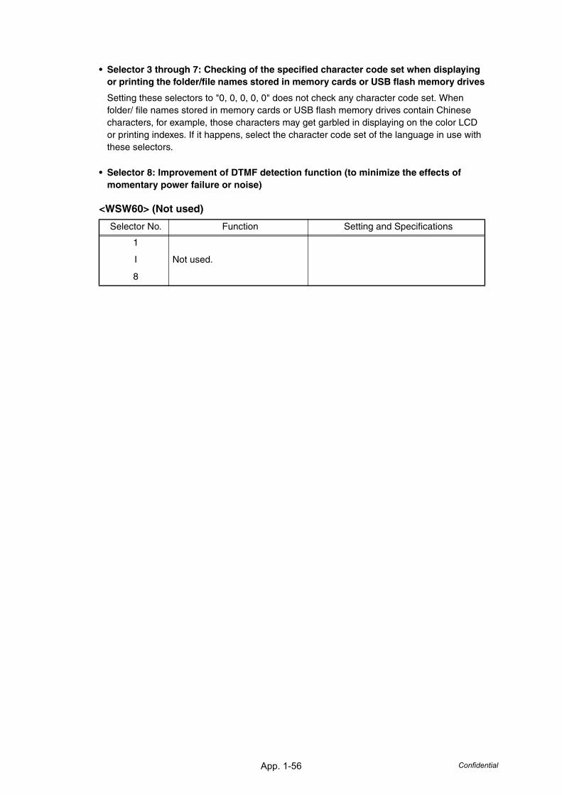
App. 1-56 Confidential
• Selector 3 through 7: Checking of the specified character code set when displaying or printing the folder/file names stored in memory cards or USB flash memory drives
Setting these selectors to "0, 0, 0, 0, 0" does not check any character code set. When folder/ file names stored in memory cards or USB flash memory drives contain Chinese characters, for example, those characters may get garbled in displaying on the color LCD or printing indexes. If it happens, select the character code set of the language in use with these selectors.
• Selector 8: Improvement of DTMF detection function (to minimize the effects of momentary power failure or noise)
<WSW60> (Not used)
Selector No. Function Setting and Specifications
1
I
8
Not used.
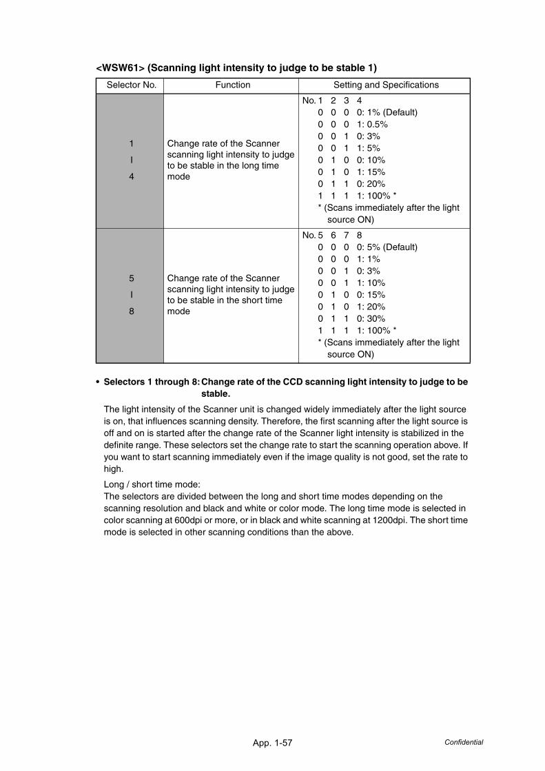
App. 1-57 Confidential
<WSW61> (Scanning light intensity to judge to be stable 1)
• Selectors 1 through 8:Change rate of the CCD scanning light intensity to judge to be stable.
The light intensity of the Scanner unit is changed widely immediately after the light source is on, that influences scanning density. Therefore, the first scanning after the light source is off and on is started after the change rate of the Scanner light intensity is stabilized in the definite range. These selectors set the change rate to start the scanning operation above. If you want to start scanning immediately even if the image quality is not good, set the rate to high.
Long / short time mode:The selectors are divided between the long and short time modes depending on the scanning resolution and black and white or color mode. The long time mode is selected in color scanning at 600dpi or more, or in black and white scanning at 1200dpi. The short time mode is selected in other scanning conditions than the above.
Selector No. Function Setting and Specifications
1
I
4
Change rate of the Scanner scanning light intensity to judge to be stable in the long time mode
No. 1 2 3 40 0 0 0: 1% (Default)0 0 0 1: 0.5%0 0 1 0: 3%0 0 1 1: 5%0 1 0 0: 10%0 1 0 1: 15%0 1 1 0: 20%1 1 1 1: 100% ** (Scans immediately after the light source ON)
5
I
8
Change rate of the Scanner scanning light intensity to judge to be stable in the short time mode
No. 5 6 7 80 0 0 0: 5% (Default)0 0 0 1: 1%0 0 1 0: 3%0 0 1 1: 10%0 1 0 0: 15%0 1 0 1: 20%0 1 1 0: 30%1 1 1 1: 100% ** (Scans immediately after the light source ON)
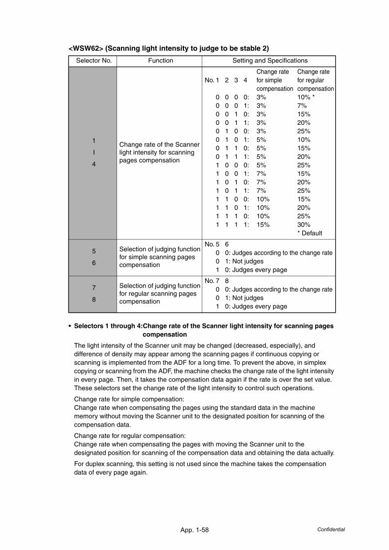
App. 1-58 Confidential
<WSW62> (Scanning light intensity to judge to be stable 2)
• Selectors 1 through 4:Change rate of the Scanner light intensity for scanning pages compensation
The light intensity of the Scanner unit may be changed (decreased, especially), and difference of density may appear among the scanning pages if continuous copying or scanning is implemented from the ADF for a long time. To prevent the above, in simplex copying or scanning from the ADF, the machine checks the change rate of the light intensity in every page. Then, it takes the compensation data again if the rate is over the set value. These selectors set the change rate of the light intensity to control such operations.
Change rate for simple compensation:Change rate when compensating the pages using the standard data in the machine memory without moving the Scanner unit to the designated position for scanning of the compensation data.
Change rate for regular compensation:Change rate when compensating the pages with moving the Scanner unit to the designated position for scanning of the compensation data and obtaining the data actually.
For duplex scanning, this setting is not used since the machine takes the compensation data of every page again.
Selector No. Function Setting and Specifications
1
I
4
Change rate of the Scanner light intensity for scanning pages compensation
Change rate Change rateNo. 1 2 3 4 for simple for regular
compensation compensation0 0 0 0: 3% 10% *0 0 0 1: 3% 7%0 0 1 0: 3% 15%0 0 1 1: 3% 20%0 1 0 0: 3% 25%0 1 0 1: 5% 10%0 1 1 0: 5% 15%0 1 1 1: 5% 20%1 0 0 0: 5% 25%1 0 0 1: 7% 15%1 0 1 0: 7% 20%1 0 1 1: 7% 25%1 1 0 0: 10% 15%1 1 0 1: 10% 20%1 1 1 0: 10% 25%1 1 1 1: 15% 30%
* Default
5
6
Selection of judging function for simple scanning pages compensation
No. 5 60 0: Judges according to the change rate0 1: Not judges1 0: Judges every page
7
8
Selection of judging function for regular scanning pages compensation
No. 7 80 0: Judges according to the change rate0 1: Not judges1 0: Judges every page
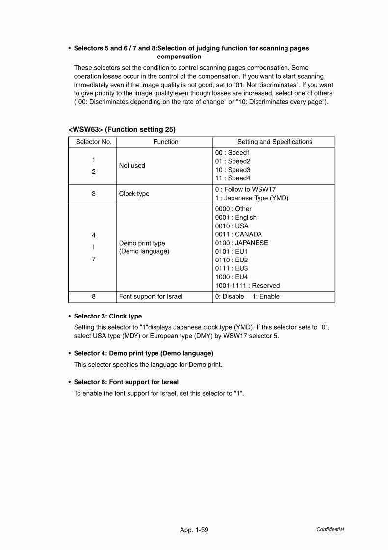
App. 1-59 Confidential
• Selectors 5 and 6 / 7 and 8:Selection of judging function for scanning pages compensation
These selectors set the condition to control scanning pages compensation. Some operation losses occur in the control of the compensation. If you want to start scanning immediately even if the image quality is not good, set to "01: Not discriminates". If you want to give priority to the image quality even though losses are increased, select one of others ("00: Discriminates depending on the rate of change" or "10: Discriminates every page").
<WSW63> (Function setting 25)
• Selector 3: Clock type
Setting this selector to "1"displays Japanese clock type (YMD). If this selector sets to "0", select USA type (MDY) or European type (DMY) by WSW17 selector 5.
• Selector 4: Demo print type (Demo language)
This selector specifies the language for Demo print.
• Selector 8: Font support for Israel
To enable the font support for Israel, set this selector to "1".
Selector No. Function Setting and Specifications
1
2Not used
00 : Speed101 : Speed210 : Speed311 : Speed4
3 Clock type0 : Follow to WSW171 : Japanese Type (YMD)
4
I
7
Demo print type (Demo language)
0000 : Other0001 : English0010 : USA0011 : CANADA0100 : JAPANESE0101 : EU10110 : EU20111 : EU31000 : EU41001-1111 : Reserved
8 Font support for Israel 0: Disable 1: Enable
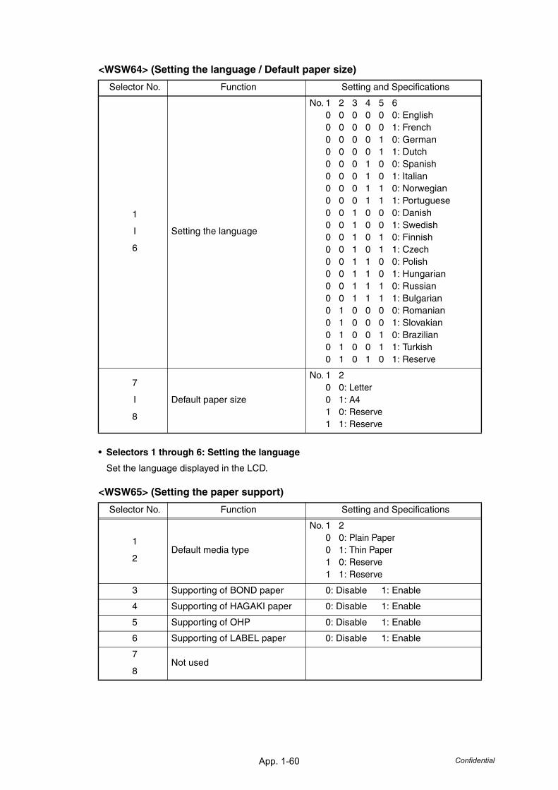
App. 1-60 Confidential
<WSW64> (Setting the language / Default paper size)
• Selectors 1 through 6: Setting the language
Set the language displayed in the LCD.
<WSW65> (Setting the paper support)
Selector No. Function Setting and Specifications
1
I
6
Setting the language
No. 1 2 3 4 5 60 0 0 0 0 0: English0 0 0 0 0 1: French0 0 0 0 1 0: German0 0 0 0 1 1: Dutch0 0 0 1 0 0: Spanish0 0 0 1 0 1: Italian0 0 0 1 1 0: Norwegian0 0 0 1 1 1: Portuguese0 0 1 0 0 0: Danish0 0 1 0 0 1: Swedish0 0 1 0 1 0: Finnish0 0 1 0 1 1: Czech0 0 1 1 0 0: Polish0 0 1 1 0 1: Hungarian0 0 1 1 1 0: Russian0 0 1 1 1 1: Bulgarian0 1 0 0 0 0: Romanian0 1 0 0 0 1: Slovakian0 1 0 0 1 0: Brazilian0 1 0 0 1 1: Turkish0 1 0 1 0 1: Reserve
7
I
8
Default paper size
No. 1 20 0: Letter0 1: A41 0: Reserve1 1: Reserve
Selector No. Function Setting and Specifications
1
2Default media type
No. 1 20 0: Plain Paper0 1: Thin Paper1 0: Reserve1 1: Reserve
3 Supporting of BOND paper 0: Disable 1: Enable
4 Supporting of HAGAKI paper 0: Disable 1: Enable
5 Supporting of OHP 0: Disable 1: Enable
6 Supporting of LABEL paper 0: Disable 1: Enable
7
8Not used
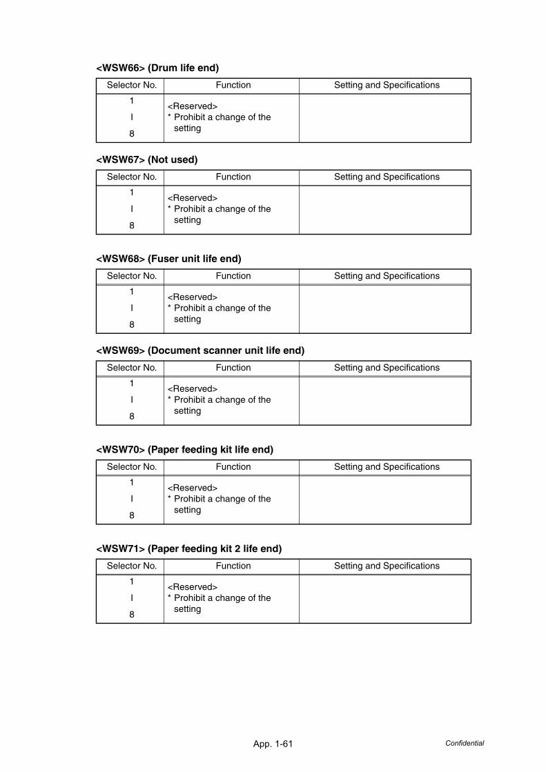
App. 1-61 Confidential
<WSW66> (Drum life end)
<WSW67> (Not used)
<WSW68> (Fuser unit life end)
<WSW69> (Document scanner unit life end)
<WSW70> (Paper feeding kit life end)
<WSW71> (Paper feeding kit 2 life end)
Selector No. Function Setting and Specifications
1
I
8
<Reserved>* Prohibit a change of the
setting
Selector No. Function Setting and Specifications
1
I
8
<Reserved>* Prohibit a change of the
setting
Selector No. Function Setting and Specifications
1
I
8
<Reserved>* Prohibit a change of the
setting
Selector No. Function Setting and Specifications
1
I
8
<Reserved>* Prohibit a change of the
setting
Selector No. Function Setting and Specifications
1
I
8
<Reserved>* Prohibit a change of the
setting
Selector No. Function Setting and Specifications
1
I
8
<Reserved>* Prohibit a change of the
setting
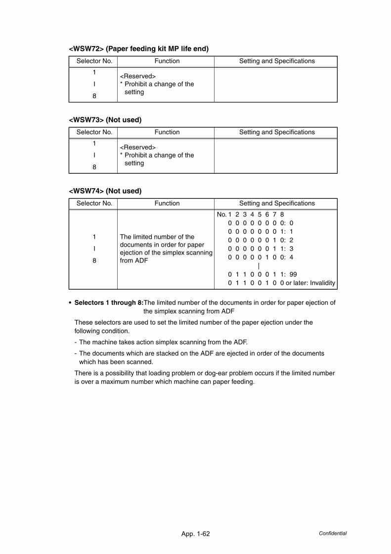
App. 1-62 Confidential
<WSW72> (Paper feeding kit MP life end)
<WSW73> (Not used)
<WSW74> (Not used)
• Selectors 1 through 8:The limited number of the documents in order for paper ejection of the simplex scanning from ADF
These selectors are used to set the limited number of the paper ejection under the following condition.
- The machine takes action simplex scanning from the ADF.
- The documents which are stacked on the ADF are ejected in order of the documents which has been scanned.
There is a possibility that loading problem or dog-ear problem occurs if the limited number is over a maximum number which machine can paper feeding.
Selector No. Function Setting and Specifications
1
I
8
<Reserved>* Prohibit a change of the
setting
Selector No. Function Setting and Specifications
1
I
8
<Reserved>* Prohibit a change of the
setting
Selector No. Function Setting and Specifications
1
I
8
The limited number of the documents in order for paper ejection of the simplex scanning from ADF
No. 1 2 3 4 5 6 7 80 0 0 0 0 0 0 0: 00 0 0 0 0 0 0 1: 10 0 0 0 0 0 1 0: 20 0 0 0 0 0 1 1: 30 0 0 0 0 1 0 0: 4
|0 1 1 0 0 0 1 1: 990 1 1 0 0 1 0 0 or later: Invalidity
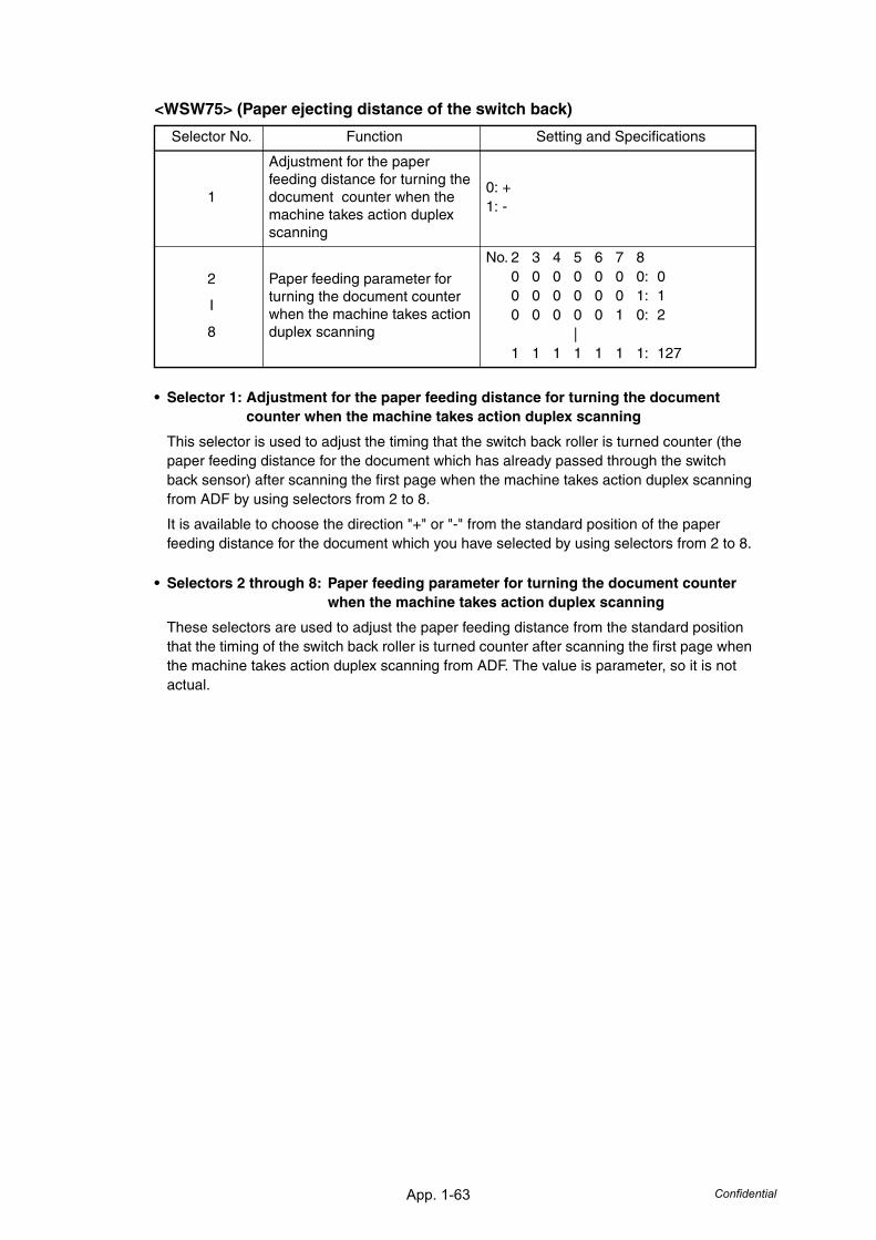
App. 1-63 Confidential
<WSW75> (Paper ejecting distance of the switch back)
• Selector 1: Adjustment for the paper feeding distance for turning the document counter when the machine takes action duplex scanning
This selector is used to adjust the timing that the switch back roller is turned counter (the paper feeding distance for the document which has already passed through the switch back sensor) after scanning the first page when the machine takes action duplex scanning from ADF by using selectors from 2 to 8.
It is available to choose the direction "+" or "-" from the standard position of the paper feeding distance for the document which you have selected by using selectors from 2 to 8.
• Selectors 2 through 8: Paper feeding parameter for turning the document counter when the machine takes action duplex scanning
These selectors are used to adjust the paper feeding distance from the standard position that the timing of the switch back roller is turned counter after scanning the first page when the machine takes action duplex scanning from ADF. The value is parameter, so it is not actual.
Selector No. Function Setting and Specifications
1
Adjustment for the paper feeding distance for turning the document counter when the machine takes action duplex scanning
0: +1: -
2
I
8
Paper feeding parameter for turning the document counter when the machine takes action duplex scanning
No. 2 3 4 5 6 7 80 0 0 0 0 0 0: 00 0 0 0 0 0 1: 10 0 0 0 0 1 0: 2
|1 1 1 1 1 1 1: 127
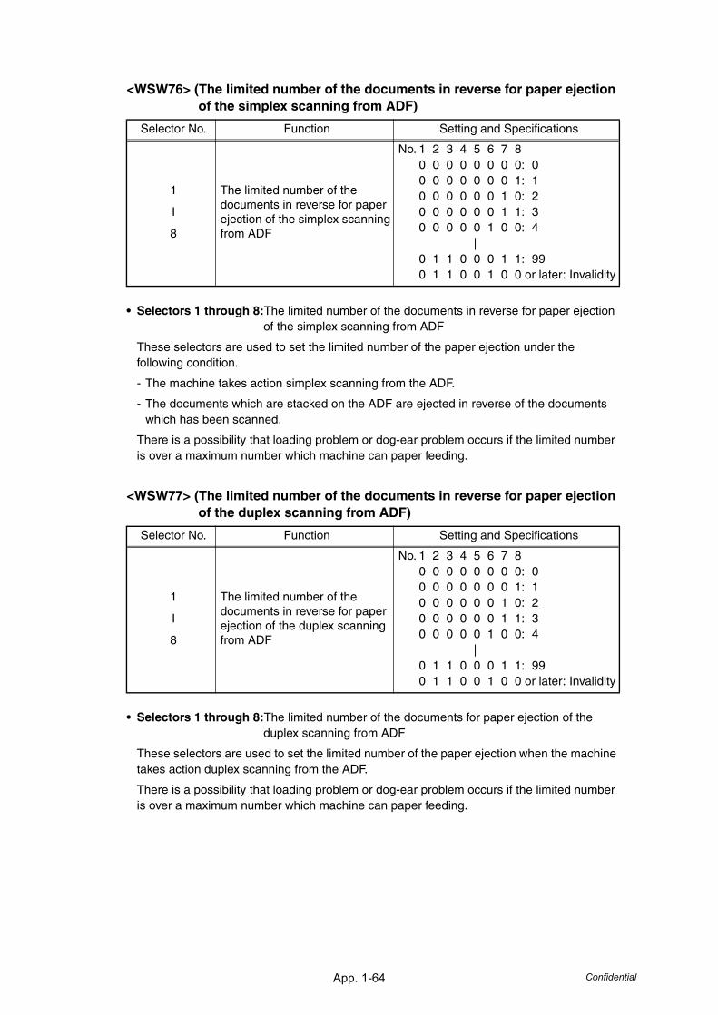
App. 1-64 Confidential
<WSW76> (The limited number of the documents in reverse for paper ejection of the simplex scanning from ADF)
• Selectors 1 through 8:The limited number of the documents in reverse for paper ejection of the simplex scanning from ADF
These selectors are used to set the limited number of the paper ejection under the following condition.
- The machine takes action simplex scanning from the ADF.
- The documents which are stacked on the ADF are ejected in reverse of the documents which has been scanned.
There is a possibility that loading problem or dog-ear problem occurs if the limited number is over a maximum number which machine can paper feeding.
<WSW77> (The limited number of the documents in reverse for paper ejection of the duplex scanning from ADF)
• Selectors 1 through 8:The limited number of the documents for paper ejection of the duplex scanning from ADF
These selectors are used to set the limited number of the paper ejection when the machine takes action duplex scanning from the ADF.
There is a possibility that loading problem or dog-ear problem occurs if the limited number is over a maximum number which machine can paper feeding.
Selector No. Function Setting and Specifications
1
I
8
The limited number of the documents in reverse for paper ejection of the simplex scanning from ADF
No. 1 2 3 4 5 6 7 80 0 0 0 0 0 0 0: 00 0 0 0 0 0 0 1: 10 0 0 0 0 0 1 0: 20 0 0 0 0 0 1 1: 30 0 0 0 0 1 0 0: 4
|0 1 1 0 0 0 1 1: 990 1 1 0 0 1 0 0 or later: Invalidity
Selector No. Function Setting and Specifications
1
I
8
The limited number of the documents in reverse for paper ejection of the duplex scanning from ADF
No. 1 2 3 4 5 6 7 80 0 0 0 0 0 0 0: 00 0 0 0 0 0 0 1: 10 0 0 0 0 0 1 0: 20 0 0 0 0 0 1 1: 30 0 0 0 0 1 0 0: 4
|0 1 1 0 0 0 1 1: 990 1 1 0 0 1 0 0 or later: Invalidity

APPENDIX 2DELETION OF USER SETTING INFORMATION, etc.This appendix describes how to delete user setting information, etc.
Confidential
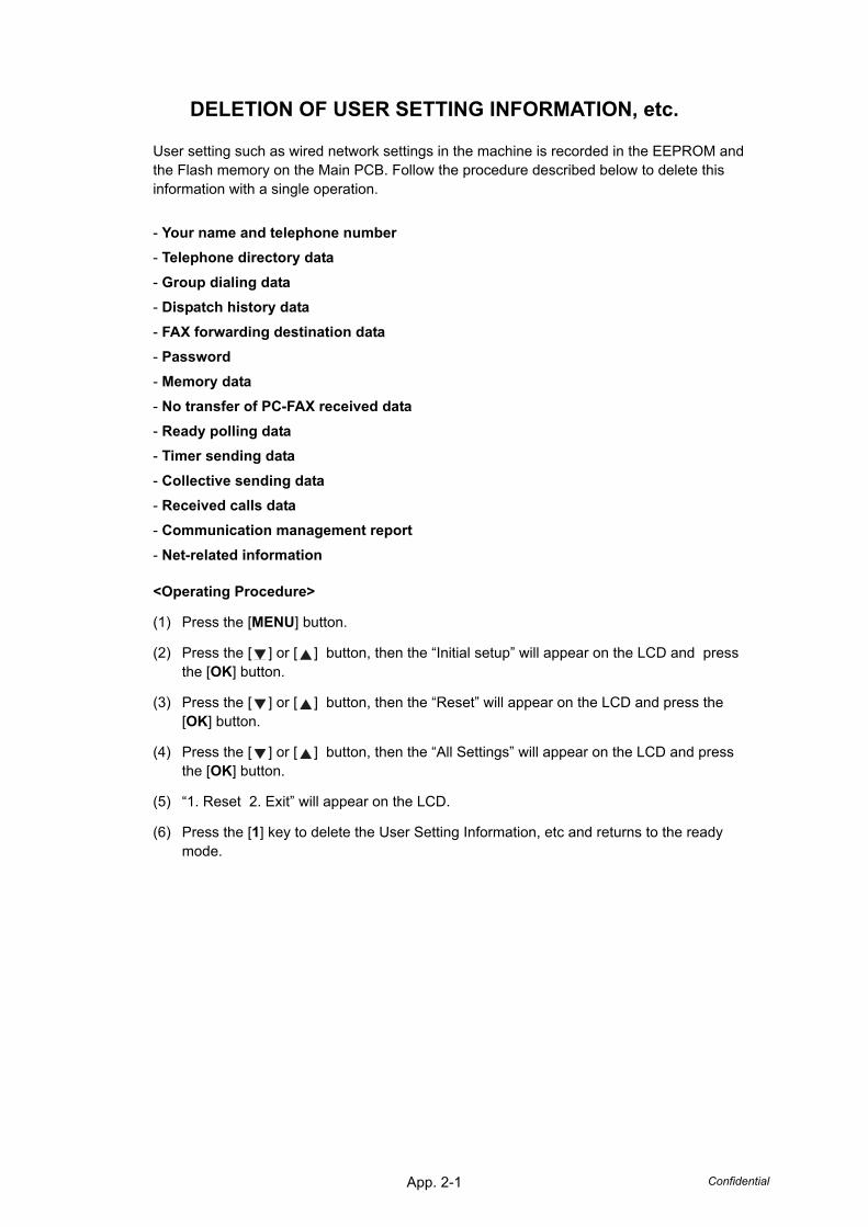
App. 2-1 Confidential
DELETION OF USER SETTING INFORMATION, etc.
User setting such as wired network settings in the machine is recorded in the EEPROM and the Flash memory on the Main PCB. Follow the procedure described below to delete this information with a single operation.
- Your name and telephone number- Telephone directory data- Group dialing data- Dispatch history data- FAX forwarding destination data- Password- Memory data- No transfer of PC-FAX received data - Ready polling data- Timer sending data- Collective sending data- Received calls data- Communication management report- Net-related information
<Operating Procedure>
(1) Press the [MENU] button.
(2) Press the [ ] or [ ] button, then the “Initial setup” will appear on the LCD and press the [OK] button.
(3) Press the [ ] or [ ] button, then the “Reset” will appear on the LCD and press the [OK] button.
(4) Press the [ ] or [ ] button, then the “All Settings” will appear on the LCD and press the [OK] button.
(5) “1. Reset 2. Exit” will appear on the LCD.
(6) Press the [1] key to delete the User Setting Information, etc and returns to the ready mode.

APPENDIX 3SCREW CATALOGUEThis appendix describes the used all screws in this machine by actual size. Use this appendix when lose the screw type.
Confidential
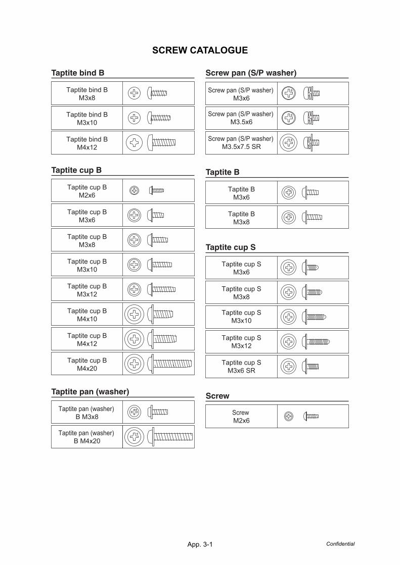
App. 3-1 Confidential
SCREW CATALOGUE
ScrewTaptite pan (washer)
Taptite cup S
Taptite B
Screw pan (S/P washer) Taptite bind B
Taptite cup B
Taptite bind BM4x12
Taptite bind BM3x10
Taptite bind BM3x8
Taptite cup BM3x12
Taptite cup BM3x8
Taptite cup BM2x6
Taptite cup BM3x6
Taptite cup BM4x10
Taptite cup BM4x12
Taptite cup BM4x20
Taptite cup BM3x10
Taptite pan (washer) B M3x8
Taptite pan (washer) B M4x20
Screw pan (S/P washer) M3.5x7.5 SR
Screw pan (S/P washer) M3.5x6
Screw pan (S/P washer) M3x6
Taptite BM3x6
Taptite BM3x8
Screw M2x6
Taptite cup SM3x6
Taptite cup SM3x6 SR
Taptite cup SM3x8
Taptite cup SM3x10
Taptite cup SM3x12

APPENDIX 4REFERENCESThis page provides the retrieve information. It is possible to get the instruction of the subject by just clicking on the link next page.
Confidential
App. 4-1 Confidential
REFERENCES
This page provides reference information. It is possible to get the full instructions of the subjects listed by just clicking on the links below.
1. Error codes(Refer to "3. ERROR CODES" in Chapter 3.)
2. Error message(Refer to "2. DISTINGUISH ERROR CAUSE" in Chapter 3.)
3. Diameter of rollers(Refer to "5.2 The pitch which appears in the image caused by failure of a roller." in Chapter 3.)
4. Periodical maintenance parts(Refer to "1.1 Periodical Maintenance Parts" in Chapter 4.)
5. Reset parts life(Refer to "5.1 Resetting the Periodical Maintenance Parts Life" in Chapter 6.)
6. Machine specification(Refer to "2. SPECIFICATIONS LIST" in Chapter 1.)
7. Paper specification(Refer to "2.6 Paper" in Chapter 1.)

APPENDIX 5GLOSSARYThis appendix describes the manual specific acronyms and technical terms that are used in addition to the generally used ones. The next page contains typical acronyms and technical terms that are used throughout these manuals.
Confidential
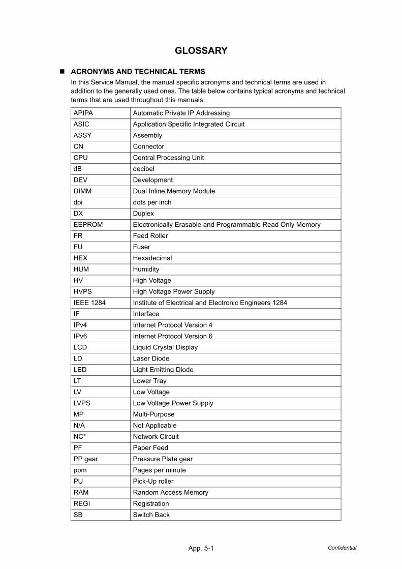
App. 5-1 Confidential
GLOSSARY
ACRONYMS AND TECHNICAL TERMSIn this Service Manual, the manual specific acronyms and technical terms are used in addition to the generally used ones. The table below contains typical acronyms and technical terms that are used throughout this manuals.
APIPA Automatic Private IP AddressingASIC Application Specific Integrated CircuitASSY AssemblyCN ConnectorCPU Central Processing UnitdB decibelDEV DevelopmentDIMM Dual Inline Memory Moduledpi dots per inch DX DuplexEEPROM Electronically Erasable and Programmable Read Only MemoryFR Feed RollerFU FuserHEX HexadecimalHUM HumidityHV High VoltageHVPS High Voltage Power SupplyIEEE 1284 Institute of Electrical and Electronic Engineers 1284IF InterfaceIPv4 Internet Protocol Version 4IPv6 Internet Protocol Version 6LCD Liquid Crystal DisplayLD Laser DiodeLED Light Emitting DiodeLT Lower TrayLV Low VoltageLVPS Low Voltage Power SupplyMP Multi-PurposeN/A Not ApplicableNC* Network CircuitPF Paper FeedPP gear Pressure Plate gearppm Pages per minutePU Pick-Up rollerRAM Random Access MemoryREGI RegistrationSB Switch Back

App. 5-2 Confidential
* Excluding the acronym shown on the wiring diagram or circuit diagram.
SOL SolenoidSP Spare PartsSX SimplexT1 Tray 1TE Toner EmptyTHM ThermalTN TonerTR Transfer

© 2010 KONICA MINOLTA BUSINESS TECHNOLOGIES, INC.© 2010 KONICA MINOLTA BUSINESS TECHNOLOGIES, INC.
Printed in JapanPrinted in JapanDDA32R-A-FE1DDA32R-A-FE1
Use of this manual should be strictly supervised toavoid disclosure of confidential information.Use of this manual should be strictly supervised toavoid disclosure of confidential information.