Embed Size (px)
Citation preview

© KEYENCE CORPORATION, 1999 BL600-UM-3-1100 Printed in Japan
BL-600 Series Use
r’s Ma
nu
al
User’s ManualLaser Bar Code Reader
BL-600 Series
96M0355
Specifications are subject to change without notice.
KEYENCE (MALAYSIA) SDN BHDPHONE: 03-252-2211 FAX: 03-252-2131
KEYENCE (THAILAND) CO., LTDPHONE: 02-369-2777 FAX: 02-369-2775
KEYENCE TAIWAN CO., LTDPHONE: 02-2627-3100 FAX: 02-2798-8925
KEYENCE KOREA CORPORATIONPHONE: 02-563-1270 FAX: 02-563-1271
AFFILIATED COMPANIES
KEYENCE CORPORATION OF AMERICAPHONE: 201-930-0100 FAX: 201-930-0099
KEYENCE DEUTSCHLAND GmbHPHONE: 06102-36 89-0 FAX: 06102-36 89-100
KEYENCE (UK) LIMITEDPHONE: 01908-696900 FAX: 01908-696777
KEYENCE FRANCE S.A.PHONE: 01 47 92 76 76 FAX: 01 47 92 76 77
KEYENCE SINGAPORE PTE LTDPHONE: 392-1011 FAX: 392-5055
KEYENCE CORPORATION1-3-14, Higashi-Nakajima, Higashi-Yodogawa-ku,Osaka, 533-8555, JapanPHONE: 81-6-6379-2211 FAX: 81-6-6379-2131

Safety Precautions
This instruction manual describes the operation and function of the BL-600. Readthis manual carefully to ensure safe use and maximum performance from your BL-600. The BL-600 Series uses a semiconductor laser as light source. Before usingthe product, see "Laser Safety Precautions" on page 1 to learn the safe and correctmethod of using the BL-600 Series.
SymbolsThe following symbols alert you to important messages. Be sure to read thesemessages carefully.
Failure to follow instruction may lead to injury. (electricshock, burn, etc.)
Failure to follow instructions may lead to product damage.
Provides additional information on proper operation.
Provides reference information about the operation.
General Precautions• At startup and during operation, be sure to monitor the functions and perfor-
mance of the BL-600.
• We recommend that you take substantial safety measures to avoid any damagein the event a problem occurs.
• Do not open or modify the BL-600 or use it in any way other than described inthe specifications.
• When the BL-600 is used in combination with other instruments, functions andperformance may be degraded, depending on operating conditions and thesurrounding environment.
• Do not use the BL-600 for the purpose of protecting the human body.
WARNING
CAUTION
Note:
i
Reference:

Warnings and Cautions Specific to the BL-600
• The BL-600 uses a 5 V DC power supply. Using a different voltage level maydamage the unit.When using the KEYENCE power supply unit BL-U1, BL-U2, N-42 or N-48,select the voltage level which can be supplied by the power supply unit. If anonconforming power supply is connected, the BL-600 may be damaged.
• Before connecting or disconnecting the cable, be sure to turn off any deviceconnected to the BL-600 Series. Otherwise, the BL-600 Series may be dam-aged.
• Do not disassemble or modify the BL-600 Series, as this may cause productfailure.
• Locate cables as far as possible from high-voltage lines and power lines.Otherwise, generated noise may cause product failure or malfunctions.
• The BL-600 is a precision instrument. If the unit is dropped or shocked, it maybe damaged. Take due consideration when transporting or installing the unit.
• Do not hold the cables when carrying the units. The units may hit each otherand become damaged.
CAUTION
Incorrect
Incorrect
ii

Environments and conditions for use
To use the BL-600 Series properly and safely, do not install it in locations with thefollowing conditions. Use of the BL-600 Series in improper environments maycause fire, electric shock, product failure, damage, or malfunction.
• Locations where the BL-600 Series is exposed to direct sunlight
• Locations where the ambient temperature drops below 0°C or exceeds 45°C
• Locations where the relative humidity drops below 35% or exceeds 85%
• Locations where condensation occurs due to a sudden change in temperature
• Locations where a corrosive or flammable gas exists
• Locations exposed to dust, salt, metal particles, or greasy fumes
• Locations where the ambient light exceeds the range defined in the specifica-tions
• Locations where the BL-600 Series is directly subjected to vibration or impact
• Locations where water, oil, or chemicals may splash the BL-600 Series
• Locations where a strong magnetic or electric field is generated
If abnormal conditions are encountered
If the following conditions are encountered, turn off the special power supply unitimmediately. Continuing to use the BL-600 Series under abnormal conditions maycause fire, electric shock, or product failure.Contact your nearest KEYENCE sales office or distributor (listed at the end of thismanual) for repairs.
• Water or foreign matter enters the BL-600 Series
• The BL-600 Series is dropped or the housing is damaged.
• The BL-600 Series produces smoke or an abnormal smell
Note 1: You cannot perform any operation for 5 seconds after turning ON the BL-600. During this time, the motor rotation stabilizes. Wait for a while after turning ONthe BL-600, then start reading or another operation.
Note 2: The BL-600 Series has a housing rated as IP-65 (except for the specialpower supply unit). It is not affected if water splashes it; however, a proper readingmay not be ensured if the transmitter/receiver is dirty (fingerprints, water, oil, ordust). In such cases, wipe the dirt off with a soft cloth moistened with alcohol.
iii
CAUTION
CAUTION

iv
2
3
4
5
1
6
7
8
Appe
ndic
es
How this manual is organized
Chapter 1 Laser Safety Precautions
Chapter 2 OverviewThis chapter describes the package contents, basic system configuration, andoperation flow.
Chapter 3 Connection and WiringThis chapter describes the connections and wiring between the BL-600 Series,special power supply unit, and peripheral devices.
Chapter 4 Setup SoftwareThis chapter describes the usage of the setup software to set or perform readingtests of the BL-600.
Chapter 5 InstallationThis chapter describes the procedure and cautions for the installation of the BL-600Series and special power supply unit.
Chapter 6 Reading Operation and Other FunctionsThis chapter describes the reading operation and other functions, such as testmode, of the BL-600 Series.
Chapter 7 Serial CommunicationThis chapter describes the serial communication control.
Chapter 8 PLC LinkThis chapter describes the PLC link control.
AppendicesThe appendix includes specifications, reading characteristics, dimensions, trouble-shooting, and index.
Warranties
War
rant
ies

Contents
Chapter 1 Laser Safety Precautions
1.1 Classification .......................................................................................... 2
1.2 Warning Labels ...................................................................................... 2
1.3 Labels Location ...................................................................................... 3
1.4 Safety Consideration ............................................................................. 4
1.5 Safety Features Provided with the BL-600 Series .............................. 4
Chapter 2 Overview
2.1 Package Contents List and the BL Series Lineup .............................. 6
2.2 Part names and functions ..................................................................... 8
2.3 System Configuration and Connection/Operation Procedures ....... 12
2.3.1 Basic system configuration and connection/operation procedures for RS-232C communication ............................... 12
2.3.2 Basic system configuration and connection/operation procedures for RS-422A communication ............................... 13
2.3.3 Multi-drop link communication (RS-485) ................................................ 14
Chapter 3 Connection and Installation
3.1 Connecting BL-U1 and Wiring ............................................................ 16
3.1.1 Connecting the BL-U1, AC power supply, and BL-600 Series ............... 16
3.1.2 DIP switch setting .................................................................................. 17
3.1.3 Terminals of I/O terminal block and wiring ............................................. 18
3.1.4 Connecting RS-232C ............................................................................. 20
3.1.5 Wiring the RS-422A ............................................................................... 23
3.2 Connecting the BL-U2/N-42 and Wiring ............................................. 25
3.2.1 Connecting the BL-U2/N-42, AC power supply, and BL-600 Series ...... 25
3.2.2 Terminals of I/O terminal block and connections ................................... 26
3.2.3 Connecting RS-232C (BL-U2) ............................................................... 28
3.2.4 Connecting the N-42 to RS-422A .......................................................... 31
3.3 Wiring without the Special Power Supply Units ............................... 33
3.3.1 Pin assignments of the BL-600 Series connectorand the connecting power supply .......................................................... 33
3.3.2 I/O Wiring ............................................................................................... 34
3.3.3 RS-232C connection .............................................................................. 35
Chapter 4 Setup Software
4.1 Installing and Operating the Setup Software .................................... 38
4.1.1 Installation and operation procedures .................................................... 38
4.1.2 Installing setup software ........................................................................ 39
4.1.3 Installation/Start-up ................................................................................ 39
v

vi
4.1.4 Initial screen ........................................................................................... 40
4.1.5 Basic operation ...................................................................................... 41
4.2 Setup Procedure .................................................................................. 42
4.2.1 Model selection ...................................................................................... 42
4.2.2 [[Main]] (Operation setting) screen ......................................................... 42
4.2.3 [[Comm Settings-1]] (Communication parameters 1) screen ................. 45
4.2.4 [[Comm Settings-2]] (Communication parameters 2) screen ................. 46
4.2.5 [[Code setup]] (Bar code setting) screen ............................................... 49
4.2.6 [[Utility]] screen ...................................................................................... 53
4.3 Sending/Receiving Settings ................................................................ 54
4.3.1 Sending/receiving settings to/from the BL-600 Series ........................... 54
4.3.2 Sending/receiving settings to/from the BL-600 Series via the N-400 ..... 57
4.4 Reading/Saving/Printing File .............................................................. 59
4.4.1 [[Files]] screen ........................................................................................ 59
4.4.2 Reading a previously saved setting file .................................................. 59
4.4.3 Saving updated settings in a file ............................................................ 60
4.4.4 Comparing the contents of the file currentlybeing edited with a saved file ................................................................. 61
4.4.5 Printing contents of a setting file ............................................................ 61
4.4.6 Resetting the edited settings to the initial (factory) settings ................... 62
4.5 Using Monitor ....................................................................................... 62
4.5.1 Receiving data and checking the result ................................................. 62
4.5.2 Command transmission ......................................................................... 63
4.5.3 Starting the test mode ............................................................................ 65
3.5.4 Changing the scanning width ................................................................. 66
4.6 List of Error Messages ........................................................................ 67
4.7 Example of printing from the setup software .................................... 68
Chapter 5 Installation
5.1 Installation of the BL-600 Series ........................................................ 72
5.1.1 Situations to check for before installing the BL-600 Series .................... 72
5.1.2 Mounting angle and distance ................................................................. 74
5.1.3 Mounting the BL-600/601/600HA/601HA ............................................... 75
5.1.4 Mounting the BL-650HA/651HA ............................................................. 77
5.1.5 Mounting the BL-600 Series without the mounting bracket ................... 79
5.2 Installation of the Special Power Supply Unit ................................... 81
5.2.1 In-panel installation ................................................................................ 81
5.2.2 Installing the BL-U1 ................................................................................ 81
5.2.2 Installing the BL-U2 and N-42 ................................................................ 83
Chapter 6 Functions for Reading Operation
6.1 Read Operation .................................................................................... 86
6.1.1 Scanning method ................................................................................... 86
6.2 Read Modes .......................................................................................... 88
6.2.1 Single label read mode .......................................................................... 88

6.2.2 Multi-label read mode 1 (Multi 1) ........................................................... 89
6.2.3 Multi-label read mode 2 (Multi 2) ........................................................... 90
6.2.4 Multi-label read mode 3 (Multi 3) ........................................................... 91
6.3 Label Orientation Mode ....................................................................... 93
6.4 Test Mode ............................................................................................. 94
6.4.1 Reading rate check mode ...................................................................... 94
6.4.2 Tact check mode .................................................................................... 97
6.4.3 Online test mode .................................................................................... 99
6.5 Preset Function (Compare with:) ..................................................... 101
6.5.1 Preset function ..................................................................................... 101
6.5.2 Using “?” and “!” in the preset data ...................................................... 101
6.6 Additional information function ....................................................... 102
6.6.1 Decode match count add function ....................................................... 102
6.6.2 Scan count add function(valid only if using the decoding count add function) ........................... 102
6.6.3 Code type add function ........................................................................ 103
6.6.4 Label orientation add function .............................................................. 103
6.6.5 Symbology ID add function .................................................................. 104
6.6.6 PMI add function .................................................................................. 104
6.6.7 Order of the additional information ....................................................... 106
6.7 Max. Code Length (Designated Digit ) Output Function ................ 107
Chapter 7 Serial Communication
7.1 Serial Communication ....................................................................... 110
7.2 Details on Data Communication ....................................................... 111
7.3 Command Communication ............................................................... 114
7.3.1 Setup of direct control commands ....................................................... 114
7.3.2 Details on parameter setting commands ............................................. 118
Chapter 8 PLC Link
8.1 PLC Link ............................................................................................. 130
8.1.1 List of PLCs used for PLC link ............................................................. 130
8.1.2 Devices used for PLC link .................................................................... 131
8.2 Setting the BL-600 and PLC .............................................................. 132
8.2.1 Setting the BL-600 Series .................................................................... 132
8.2.2 Setting the PLC .................................................................................... 132
8.3 Device Assignment ............................................................................ 135
8.3.1 Data memory head address ................................................................. 135
8.3.2 Data memory areas ............................................................................. 136
8.3.3 Detailed description of device assignment ........................................... 137
8.4 PLC Link Error .................................................................................... 142
8.5 Communication Time ........................................................................ 143
vii

viii
Appendices
Appendix A BL-600 Series Specifications ............................................... 146
Appendix A.1 Specifications .......................................................................... 146
Appendix A.2 Reading Range Characteristics (Typical) ............................... 148
Appendix A.3 Angular Characteristics (Typical) ............................................ 151
Appendix B BL-U1 Specifications ............................................................ 152
Appendix C BL-U2, N-42 Specifications .................................................. 153
Appendix D Dimensions ........................................................................... 154
Appendix E Sample Program for the PLC Link ...................................... 159
Appendix F Troubleshooting ................................................................... 162
Appendix F.1 Bar codes cannot be read ....................................................... 162
Appendix F.2 Reading rate check mode is not 100% ................................... 163
Appendix F.3 The setting data cannot be sent/received using the setup software .......................................... 163
Appendix F.4 Cannot communicate successfully when using the PLC link ..... 163
Appendix G CODE93 Specifications ........................................................ 164
Appendix H CODE128 Specifications ...................................................... 165
Appendix I Checksum Calculation Method ........................................... 167
Appendix J ASCII Code Table .................................................................. 169
Appendix K Setup Parameter List ............................................................ 170
Appendix L Default Setting List ............................................................... 173
Warranties
WARRANTIES AND DISCLAIMERS ............................................................ 181

ix

Chapter 1Laser Safety Precautions
1.1 Classification ........................................................................ 2
1.2 Warning Labels ..................................................................... 2
1.3 Label Location ...................................................................... 3
1.4 Safety Consideration ............................................................ 4
1.5 Safety Features Provided with the BL-600 Series ............. 4

Chapter 1 Laser Safety Precautions
1
2
1.1 ClassificationModel BL-600/601/600HA/601HA BL-650HA/651HA
FDA Class II
IEC 825-1 11.1993 Class 2
DIN EN 60825-1 07.1994 Klasse 2
1.2 Warning Labels
1) Warning labels FDA
BL-600/601/600HA/601HA BL-650HA/651HA
IECBL-600/601/600HA/601HA BL-650HA/651HA
DIN
BL-600/601/600HA/601HA BL-650HA/651HA
2) Protective housing label FDA IEC DIN
LASER RADIATIONWHEN OPEN.DO NOT STAREINTO BEAM.
CAUTIONLASER RADIATION-DO NOT STARE INTO BEAM.
LASER RADIATIONIS EMITTED FROMTHIS APERTURE.
SEMICONDUCTOR LASER 650 nmMAXIMUM OUTPUT 1.5 mWPULSE DURATION 56 µsCLASS II LASER PRODUCT
AVOID EXPOSURE
CAUTION
CAUTIONLASER RADIATION-DO NOT STARE INTO BEAM.
AVOID EXPOSURELASER RADIATIONIS EMITTED FROMTHIS APERTURE.
SEMICONDUCTOR LASER 650 nmMAXIMUM OUTPUT 1.5 mWPULSE DURATION 56 µsCLASS II LASER PRODUCT
LASER RADIATIONDO NOT STARE INTO BEAM
Maximum outputPulse durationEmitted wavelength
1.5 mW82 µs
650 nm
CLASS 2 LASER PRODUCTin conformity to IEC 60825-1 1998-01
LASER RADIATIONDO NOT STARE INTO BEAM
Maximum outputPulse durationEmitted wavelength
CLASS 2 LASER PRODUCT
1.5 mW99 µs
650 nm
in conformity to IEC 60825-1 1998-01
CAUTION - Laser radiation when open. Do not stare into beam.
LASERSTRAHLUNGNICHT IN DEN STRAHL BLICKEN
1.5 mW82 µs
650 nm
Maximum Leistung Pulsdauer Wellenlänge
LASER KLASSE 2nach Entwurf DIN EN60825-1 1998-01LASERSTRAHLUNG
NICHT IN DEN STRAHL BLICKENMaximum LeistungPulsdauer Wellenlänge
LASER KLASSE 2
1.5 mW99 µs
650 nm
nach Entwurf DIN EN 60825-1 1998-01
VORSICHT- Laserstrahlung wenn Abdeckunggeöffnet. Nicht in den Strahl blicken.
CAUTION - Laser radiation when open. Do not stare into beam.
VORSICHT- Laserstrahlung wenn Abdeckunggeöffnet. Nicht in den Strahl blicken.
CAUTION-LASER RADIATION WHEN OPEN. DO NOT STARE INTO BEAM.

Chapter 1 Laser Safety Precautions
1
3
1.3 Labels Location
FDA Warning labels are attached to the sensor head as shown below.The IEC/DIN Warning labels are packaged with the BL-600 series. Affix the Warn-ing labels on the sensor head as shown below.
BL-600/601/600HA/601HA
FDA IEC
DIN
BL-650HA/651HA
FDA IEC
DIN
LASER ON
OK/NG
TIMING
TEST
BL-600
LASER RADIATIONWHEN OPEN.DO NOT STAREINTO BEAM.
CAUTIONLASER RADIATION-DO NOT STARE INTO BEAM.
LASER RADIATIONIS EMITTED FROMTHIS APERTURE.
SEMICONDUCTOR LASER 650 nmMAXIMUM OUTPUT 1.5 mWPULSE DURATION 56 µsCLASS II LASER PRODUCT
AVOID EXPOSURE
CAUTION
LASER ONOK/NGTIMING
TEST
BL-600
CAUTIONLASER RADIATION-DO NOT STARE INTO BEAM.
AVOID EXPOSURELASER RADIATIONIS EMITTED FROMTHIS APERTURE.
SEMICONDUCTOR LASER 650 nmMAXIMUM OUTPUT 1.5 mWPULSE DURATION 56 µsCLASS II LASER PRODUCT
CAUTION-LASER RADIATION WHEN OPEN. DO NOT STARE INTO BEAM.
LASER ON
OK/NG
TIMING
TEST
BL-600
LASER RADIATIONDO NOT STARE INTO BEAM
Maximum outputPulse durationEmitted wavelength
CLASS 2 LASER PRODUCT
1.5 mW99 µs
650 nm
in conformity to IEC 60825-1 1998-01
CAUTION - Laser radiation when open. Do not stare into beam.
LASER ON
OK/NG
TIMING
TEST
BL-600
LASERSTRAHLUNGNICHT IN DEN STRAHL BLICKEN
Maximum LeistungPulsdauer Wellenlänge
LASER KLASSE 2
1.5 mW99 µs
650 nm
nach Entwurf DIN EN 60825-1 1998-01
VORSICHT- Laserstrahlung wenn Abdeckunggeöffnet. Nicht in den Strahl blicken.
LASER ONOK/NGTIMING
TEST
BL-600
LASER RADIATIONDO NOT STARE INTO BEAM
Maximum outputPulse durationEmitted wavelength
1.5 mW82 µs
650 nm
CLASS 2 LASER PRODUCTin conformity to IEC 60825-1 1998-01
CAUTION - Laser radiation when open. Do not stare into beam.
LASER ONOK/NGTIMING
TEST
BL-600
LASERSTRAHLUNGNICHT IN DEN STRAHL BLICKEN
1.5 mW82 µs
650 nm
Maximum Leistung Pulsdauer Wellenlänge
LASER KLASSE 2nach Entwurf DIN EN60825-1 1998-01
VORSICHT- Laserstrahlung wenn Abdeckunggeöffnet. Nicht in den Strahl blicken.

Chapter 1 Laser Safety Precautions
1
4
1.4 Safety Consideration
Use of controls or adjustment, or the performance of procedures other than thosespecified herein, may result in hazardous radiation exposure.
The laser beam is not harmful to the skin. There is, therefore, no danger in expos-ing arms or hands to the beam. The only possible health hazard is in exposing theeyes to the laser beam. Damage to the eyes can occur if the operator staresdirectly into the beam.
Follow the safety precautions below to ensure operator safety:• Operate the BL-600 Series only according to the procedures described in
this instruction manual.Otherwise, injury may occur due to exposure to the laser beam.
• Do not disassemble the sensor head.Laser emission from the BL-600 series is not automatically stopped if thesensor head is disassembled. If you disassemble the sensor head for inspectionor repair, you may be exposed to the laser beam. If the BL-600 series malfunc-tions, contact KEYENCE immediately.
• Do not look directly at the laser beam.Looking directly at the laser beam may result in serious eye injury.
• Protective enclosureWe recommend that you install a protective enclosure around the sensor headto prevent any person from getting near the sensor head during operation.
• Protective gogglesWe recommend that you wear protective goggles when using the BL-600series.
• Stop laser emissions before cleaning the laser emission port.Failure to stop the laser emission may expose eyes to the laser beam.
• Check the laser beam path.To prevent exposure to the laser beam due to specular or diffuse reflection,install a screen which offers the appropriate reflectance and temperaturecharacteristics to interrupt the reflected laser beam. Do not install the BL-600series in such a way that the laser beam passes at eye height.
1.5 Safety Features Provided with the BL-600 Series
The BL-600 series is provided with the following safety features. Make sure thesefeatures function correctly before operating.
• Laser emission caution LED (LASER ON LED)
During laser emission, the LASER ON LED illuminates. The LED ON status canbe checked through the laser protective glasses.
• Laser forced OFF command
Sending the laser forced OFF command (LOCK, see page 116) to the BL-600can inhibit emission of laser beams. When working near the laser transmitter,be sure to use the laser forced OFF command to avoid looking into the laserbeams.
When this command is selected, the bottom STABILITY LED flashes.
CAUTION
WARNING

Chapter 2OverviewThis chapter describes the package contents, basic system configuration, andoperation flow.
2.1 Package Contents List and the BL Series Lineup .............. 6
2.2 Part Names and Functions ................................................... 8
2.3 System Configuration and Connection/Operation Procedures ......................................................... 12
2.3.1 Basic system configuration and connection/operation proce-dures for RS-232C communication........................................ 12
2.3.2 Basic system configuration and connection/operation proce-dures for RS-422A communication ........................................ 13
2.3.3 Multi-drop link communication (RS-485)................................ 14

Chapter 2 Overview
2
6
2.1 Package Contents List and the BL Series Lineup
The packages of the BL-600 Series, optional power supply unit, and setup softwarecontain the following components. Be sure to check that you have all the packagecontents before use.
Laser bar code reader
BL-600 Series (BL-600/601/600HA/601HA/650HA/651HA)
Laser bar code reader: 1BL-600/601/600HA/601HA BL-650HA/651HA Insulating spacer: 4
Washer: 4
Mounting screw (M3): 2
BL-600/601/600HA/601HA BL-650HA/651HAMounting bracket Mounting bracket : 1 Instruction manual: 1A and B: 1 each
Laser warning label (Japanese/English/German/French): 1BL-600/601/600HA/601HA BL-650HA/651HA
LASER ON
OK/NG
TIMING
TESTLASER ONOK/NGTIMING
TEST
LASER RADIATIONDO NOT STARE INTO BEAM
Maximum outputPulse durationEmitted wavelength
CLASS 2 LASER PRODUCT
1.5 mW99 µs
650 nm
in conformity to IEC 60825-1 1998-01
CAUTION - Laser radiation when open. Do not stare into beam.
LASER RADIATIONDO NOT STARE INTO BEAM
Maximum outputPulse durationEmitted wavelength
1.5 mW82 µs
650 nm
CLASS 2 LASER PRODUCTin conformity to IEC 60825-1 1998-01
CAUTION - Laser radiation when open. Do not stare into beam.
ledoMgnidaeRnoitcerid
gninnacSdohtem
rabelbadaeRhtdiw
ecnatsidgnidaeR
006-LB
tnorF
elgniSmm0.1ot91.0
mm033ot57)mm0.1sihtdiwworrannehW(106-LB retsaR
AH006-LB elgniS
mm0.1ot521.0
mm091ot53)mm5.0sihtdiwworrannehW(AH106-LB retsaR
AH056-LBediS
elgniS mm571ot54)mm5.0sihtdiwworrannehW(AH156-LB retsaR
Laser Bar Code Reader
BL-600 SeriesInstruction Manual
058-069

Chapter 2 Overview
2
7
Power supply (Option)
BL-U1 N-42/N-48
BL-U2 D-sub 9-pin connector,connector case: 1 each
Setup software (Option)
BL-H60WE
Setup software3.5-inch floppy disk: 1
Other options
N-400: Multi-drop controllerUsed as the master unit when multi-drop linking with the BL Series.
The package contents have been carefully inspected; however, if any componentshould be defective or damaged, contact your nearest KEYENCE office or distribu-tor (listed at the end of this manual).
OP-27937: RS-232C Null modem cable (D-sub 9-pin)Used for connecting BL-600 reader to optional power supply unitsBL-U2.
OP-22149: RS-232C Null modem cableUsed for connecting BL-600 reader to optional power supply unitsBL-U1.
OP-25057: 25-to 9-pin adaptor
TERMINATOR
ONOFF
POWERSD
RDREADER
POWER SD
RD
READER
RS-232C
ledoM egatlovylppuS ecafretnI
1U-LB CAV042ot001)knilpord-itlum(584-SRro,A224-SR,C232-SR
)esehtfoenotceleS(
2U-LB CDV42 C232-SR
24-N CDV42 A224-SR
84-N CDV42 )knilpord-itlum(584-SR

Chapter 2 Overview
2
8
2.2 Part Names and Functions
This section describes the part names and functions of the BL-600 Series andspecial power supply unit.
BL-600/601/600HA/601HA BL-650HA/651HA
LASER ON
OK/NG
TIMING
TEST
BL-600
LASER ONOK/NGTIMING
TEST
BL-600
LASER ON
OK/NG
TIMING
TEST
BL-600
123
4
5
7
8
6
6
8
7
.oN emaN noitcnuF1 DELNORESAL .dettimeerasmaebresalnehwtiL
2 DELGN/KO.sthgilDELneergehT:NOsituptuoKOnehW•
.sthgilDELderehT:NOsituptuoGNnehW•3 DELGNIMIT .NOsitupnireggirtnehwtiL
4 DELYTILIBATSytilibatsgnidaerehtsyalpsiD ( ).001,89,59segapeeS
.sutatsgnitarepo006-LBehtdna ( ehtnoelbatehteeS).egaptxen
5 HCTIWSTSET
:snoitarepogniwollofehtswollahctiwssihT.edomtxetehttratS•
sdaersetunimowtnihtiwecnohctiwsehtgnisserP•.ecnoedocrabeht
ehtotlocotorpnoitacinummocehtsteS• seulavlavitni.sgnittesehtgnidnesnehw ( ).45egapeeS
.sutatsrorreehtteseR•
6 reviecer/rettimsnarTdetcelfereviecerdnasmaebresaltimeotwodniW
.sthgil
7 rotcennocylppusrewoP .tinuylppusrewoplaicepsehtotdetcennoC
8 elbaC .m9.1sihtgnelelbaC

Chapter 2 Overview
2
9
STABILITY LED display according to the operating status
sutatsgnitarepO yalpsidDELYTILIBATS nekatebotnoitcA
no-rewoPyllaitneuqesnonrutsDEL
.mottobehtmorfgnitrats––––––
putesgniruD .811,611segapeeS
.hsalfsDELehtllA ––––––
atadgnittesrofgnitiaWeviecer/dnes
.45egapeeS
htfifdna,driht,tsrifehThsalfpotehtmorfsDEL
.ylsuoenatlumis––––––
FFOdecrofresaL sidnammocKCOLnehW
.611egapees,tnes.sehsalfDELmottobehT ––––––
rorretinU,driht,dnocesehtforehtiE
potehtmorfsDELhtrofro.sehsalf
evahyamseireS006-LBehTyamegatlovylppusehtrodeliaf
siegatlovehtfI.deppordevahaevahyamtinueht,lamron
tseraenruoytcatnoC.melborp.rotubirtsidroeciffoECNEYEK
rorreknilCLP .241egapeeS
.sehsalfDELpotehTteserothctiwsTSETehtsserP
.rorreeht

Chapter 2 Overview
2
10
BL-U1
6
1
234
9
10
78
5
12
11
.oN emaN noitcnuF
1 DELREWOP .NOsirewopnehwtiL
2sutatsnoitacinummoC
sDELrotacidni
fosutatsnoitacinummocehtrotinomotuoyswollA•.tropC232-SReht
nidedivorperasrotacidniSCdnaSR,DR,DSehT•.potehtmorfredrosiht
3 DELGNIMIT .NOsitupnireggirtnehwtiL
4 DELGN/KO.sthgilDELneergehT:NOsituptuoKOnehW•
.sthgilDELderehT:NOsituptuoGNnehW•
5 kcolblanimretO/ItuptuoGN/KO,lanimrettupnireggirtehtsedulcnI)knilpord-itlum(584-SR/A224-SRdna,slanimret
.slanimretgnitcennoc
6 tropC232-SRsitropsihT.retupmoclanosrepaottcennocotdesU
.desusi)knilpord-itlum(584-SRnehwdesunu
7 tropREDAER .tropsihtotseireS006-LBehttcennoC
8 sehctiwsPIDehtsnrutdna,tropnoitacinummocehtsehctiwS
.FFO/NOrotanimret
9 hctiwsrewoP .FFO/NOrewopehtsnuT
01 elbacylppusrewoP.ylppusrewop)zH06/05(CAV042ot001aesU
.m2sithgnelelbaC
11 tekcarbgnitnuoM .swercshtiwdetnuomsi1U-LBehtnehwdesU
21 walcgnitnuomliar-NID .liarNIDaotdetnuomsi1U-LBehtnehwdesU

Chapter 2 Overview
2
11
BL-U2
N-42
POWER SD
RD
READER
RS-232C
8
1
23
8
4
5
67
.oN emaN noitcnuF
1 tropREDAER .redaeredocrabseireS006-LBaottcennoC
2 slanimrettupniREGGIRT .tupnireggirtrofrosnescirtceleotohpaottcennoC
3 slanimrettuptuoGN/KO .slangisGN/KOtuptuO
4 slanimretylppusrewoP .ylppusrewopCDV42aottcennoC
5 tropC232-SR .cte,retupmoclanosrepaottcennoC
6sutatsnoitacinummoC
sDELrotacidni
.C232-SRehtfosutatsnoitacinummocehtetacidnI•redrosihtnidedivorperasrotacidniDRdnaDSehT•
.potehtmorf
7 DELREWOP .nosirewopehtnehwthgiL
8 elohgnitnuoM .swercshtiwdetnuomsi2U-LBehtnehwdesU
TERMINATOR
ONOFF
POWERSD
RDREADER1
3
2
459
6
7
98
.oN emaN noitcnuF
1 tropREDAER .redaeredocrabseireS006-LBaottcennoC
2 hctiwsrotanimreTrotanimretehtFFO/NOsnruT
001:ecnatsisernoitanimreT( Ω .)
3 slanimrettupniREGGIRT .tupnireggirtrofrosnescirtceleotohpaottcennoC
4 slanimrettuptuoGN/KO .slangisGN/KOtuptuO
5 slanimretylppusrewoP .ylppusrewopCDV42aottcennoC
6 slanimretA224-SR .ecivedA224-SRnaottcennoC
7sutatsnoitacinummoC
sDELrotacidni
.A224-SRehtfosutatsnoitacinummocehtsetacidnI•redrosihtnidedivorperasrotacidniDRdnaDSehT•
.tfelehtmorf
8 DELREWOP .NOdenrutsirewopehtnehwthgiL
9 elohgnitnuoM .swercshtiwdetnuomsi24-NehtnehwdesU

Chapter 2 Overview
2
12
2.3 System Configuration and Connection/Operation Proce-dures
This section describes the basic system configuration and the connection/operationprocedures to use RS-232C, RS-422A, or multi-drop link.
2.3.1 Basic system configuration and connection/operation procedures forRS-232C communication
LASER ON
OK/NG
TIMING
TEST
LASER ONOK/NGTIMING
TEST
BL-600 Series
BL-600/601/600HA/601HA BL-650HA/651HA Installation See pages 72 to 80.
• Check before installation• Position adjustment using
test mode• Installation
Connection to the READER portWith the BL-U1 See page 16.
With the BL-U2 See page 25.
Optional power supply unit
POWER SD
RD
READER
RS-232C
6
1
Power-up
DIP switch setting See page 17.
2
4
Trigger inputPhotoelectric sensor
Host computer
3ConnectionWith the BL-U1 See pages 20 to 23.
With the BL-U2 See pages 28 to 30.
8Serial communi-cation See “Chapter 7,
Serial Communication.”
PLC link See “Chapter 8, PLC Link.”
PC PLC (RS-232C link unit)
9
7ConnectionWith the BL-U1 See page 19.
With the BL-U2 See page 27.
5Setting of the BL-600 Series(Use one of these setup tools.)
Setup toolsSetup softwareBL-H60WE See “Chapter 4, Setup
Software.”
BL-U1 BL-U2
Chapter 2 Overview
2
13
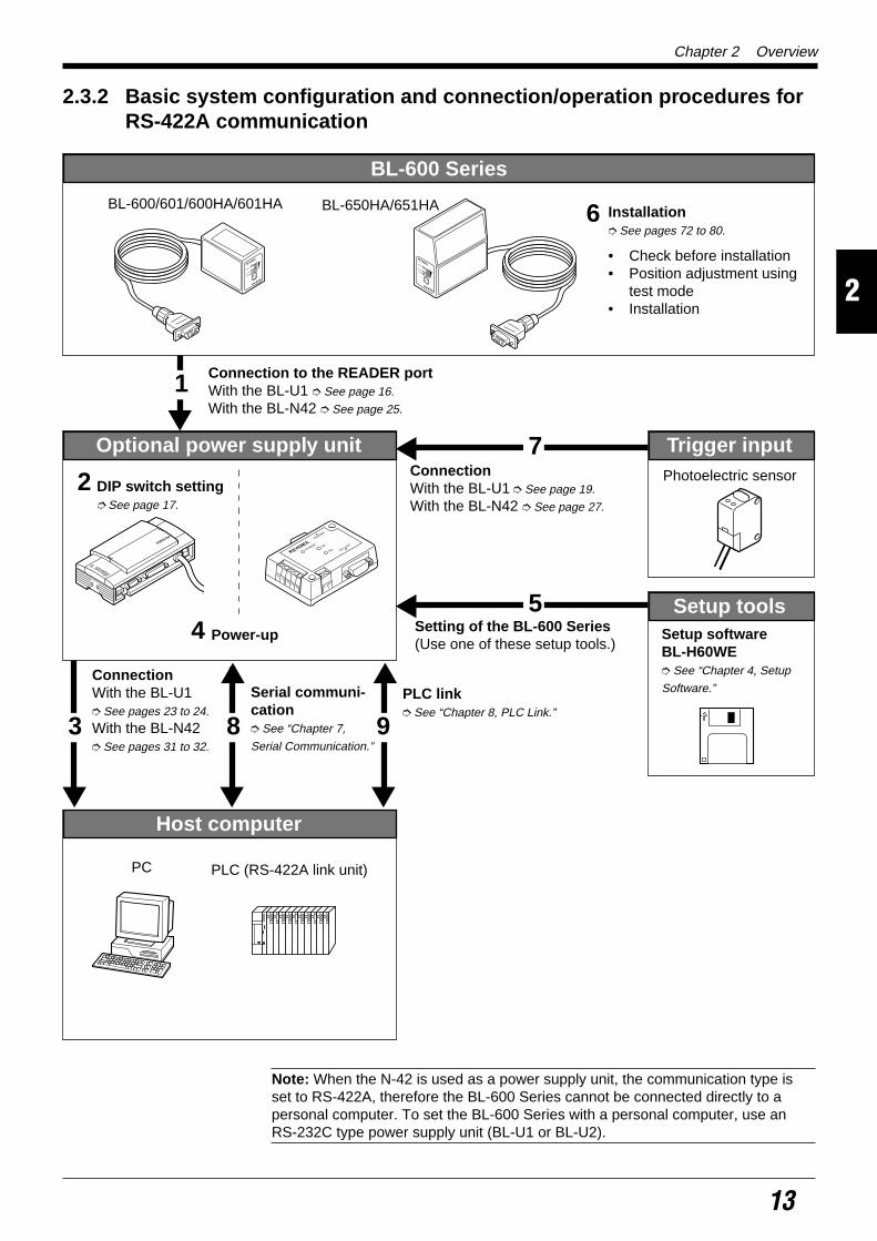
2.3.2 Basic system configuration and connection/operation procedures forRS-422A communication
LASER ON
OK/NG
TIMING
TEST
LASER ONOK/NGTIMING
TEST
BL-600 Series
BL-600/601/600HA/601HA BL-650HA/651HA Installation See pages 72 to 80.
• Check before installation• Position adjustment using
test mode• Installation
Connection to the READER portWith the BL-U1 See page 16.
With the BL-N42 See page 25.
Optional power supply unit
POWER SD
RD
READER
RS-232C
6
1
Power-up
DIP switch setting See page 17.
2
4
Trigger inputPhotoelectric sensor
Host computer
3
ConnectionWith the BL-U1 See pages 23 to 24.
With the BL-N42 See pages 31 to 32.
8
Serial communi-cation See “Chapter 7,
Serial Communication.”
PLC link See “Chapter 8, PLC Link.”
PC PLC (RS-422A link unit)
9
7ConnectionWith the BL-U1 See page 19.
With the BL-N42 See page 27.
5Setting of the BL-600 Series(Use one of these setup tools.)
Setup toolsSetup softwareBL-H60WE See “Chapter 4, Setup
Software.”
Note: When the N-42 is used as a power supply unit, the communication type isset to RS-422A, therefore the BL-600 Series cannot be connected directly to apersonal computer. To set the BL-600 Series with a personal computer, use anRS-232C type power supply unit (BL-U1 or BL-U2).

Chapter 2 Overview
2
14
2.3.3 Multi-drop link communication (RS-485)The following devices are required for the multi-drop link to control several BL-600Series units with a host computer.
BL-600 Series setup tools
Setup software BL-H60WE
N-400 setup toolsSetup software (Provided with N-400)
Refer to the N-400 User’s Manual for connection and usage of the multi-drop link.
Photoelectric sensor(PZ2 Series, etc.)
Host computer (PC)
Multi-drop controller(N-400)
BL-600 Series
Optional power supply unit(BL-U1, N-48)

Chapter 3Connection and InstallationThis chapter describes the connections and wiring between the BL-600 Series,special power supply unit, and peripheral devices.
3.1 Connecting BL-U1 and Wiring ........................................... 16
3.1.1 Connecting the BL-U1, AC power supply,and BL-600 Series ................................................................. 16
3.1.2 DIP switch setting .................................................................. 173.1.3 Terminals of I/O terminal block and wiring............................. 183.1.4 Connecting RS-232C ............................................................. 203.1.5 Wiring the RS-422A ............................................................... 23
3.2 Connecting the BL-U2/N-42 and Wiring ............................ 25
3.2.1 Connecting the BL-U2/N-42, AC power supply,and BL-600 Series ................................................................. 25
3.2.2 Terminals of I/O terminal block and connections ................... 263.2.3 Connecting RS-232C (BL-U2) ............................................... 283.2.4 Connecting the N-42 to RS-422A .......................................... 31
3.3 Wiring without the Special Power Supply Units .............. 33
3.3.1 Pin assignments of the BL-600 Series connectorand the connecting power supply .......................................... 33
3.3.2 I/O Wiring ............................................................................... 343.3.3 RS-232C connection.............................................................. 35

Chapter 3 Connection and Installation
16
3
3.1 Connecting BL-U1 and Wiring
This section describes the connection and wiring of the BL-600 Series and periph-eral devices when the special power supply unit BL-U1 is used.
3.1.1 Connecting the BL-U1, AC power supply, and BL-600 Series1. Plug the BL-U1 power cable into an outlet.
Do not use a power supply other than 100 to 240 V AC (50/60 Hz).An improper power supply may cause product failure.
Note: If the noise conveyed through the FG line causes an LB-600 Series readingerror, do not connect the FG line.
2. Connect the BL-600 Series to the READER port of the BL-U1.
BL-U1 READER port pin assignment
Note: Do not extend the power cable. A long power cable can cause a voltagedrop, preventing the BL-600 from starting properly.
BL-U1
FG line
Outlet
Power plug
CAUTION
BL-600 Series
Connector
READERport
21 3 4 5
6 7 8 9
D-sub 9-pin (male)DCE specification (defined as terminal)#4-40 screw (female)
.oNniP lobmyS noitcnuFlangiSnoitcerid
1 MIT tupnireggirT tuptuO
2 )DXR(DR .atadC232-SRsdneS tuptuO
3 )DXT(DS .atadC232-SRsevieceR tupnI
4 KO KO tupnI
5 )GS(DNG )langisevitcepserrofdnuorgnommoC(dnuorG ––
6 GN GN tupnI
7 )STR(SR .atadC232-SRdnesotydaeR tupnI
8 )STC(SC.atadC232-SRdnesottseuqeR
PIDehthtiwdetcelesebnacdohtemlortnoC().sehctiws .71egapeeS
tuptuO
9 V5+ ylppusrewopV5+ tuptuO

Chapter 3 Connection and Installation
17
3
3.1.2 DIP switch settingChange the DIP switch setting according to the type of communication and termi-nator setting.
DIP switch
OFF
ON 1 2 3 4 5 6
Switch
DIP switch* The figure above shows the factory-settings.
.oNhctiwSPID 1 2 3 4 5 6
epytnoitacinummoCnoitceles
C232-SR)gnittes-yrotcaF(
NO FFO FFO
A224-SR FFO NO FFO
584-SR)knilpord-itluM(
FFO FFO NO
rotanimretA224-SRnoitanimreT(
001:ecnatsiser Ω)
FFO FFO
NO NO
rotanimret584-SRnoitanimreT(
001:ecnatsiser Ω)
FFO FFO
NO NO
REDAERfonoitceleSdohtemlortnocSCtrop
gnidroccaFFOroNOtropC232-SRehtot
.sutatslangisSCFFO
NOyllamroN NO

Chapter 3 Connection and Installation
18
3
3.1.3 Terminals of I/O terminal block and wiringTerminals of the I/O terminal block
The terminals of the I/O terminal block are assigned as shown in the figure.
Terminal assignment
Applicable crimp terminals
M3.0 screws are used for the terminal block.Use the following crimp terminal for connection.
Shape of applicable crimp terminal
I/O terminal block
Open
TIM +12V OUT- COM OK NG SDA SDB SG RDA RDB
Trigger input RS-422A/RS-485OK/NG output
Power supply for thesensor (12 V DC, 300 mA)
lobmyS noitpircseDlangiSnoitcerid
MIT tupnireggirTtupnI
tupnI
-TUOV21+)Am003,CDV21(rosnesrofylppusrewopfolanimret+ tuptuO
)V0(rosnesrofylppusrewopfolanimret– tuptuO
MOC tuptuoGN/KOroflanimretnommoC —
KO tuptuoKO tuptuO
GN tuptuoGN tuptuO
ADS lanimret+584-SR/noissimsnartatadA224-SRroflanimret+,tuptuO
tuptuO/tupnI
BDS lanimret-584-SR/noissimsnartatadA224-SRroflanimret–,tuptuO
tuptuO/tupnI
GS dnuorglangiS —
ADR noitpeceratadA224-SRroflanimret+ tupnI
BDR noitpeceratadA224-SRroflanimret– tupnI
6.0 mm or less
Round-shape
6.0 mm or less
Fork-shape

Chapter 3 Connection and Installation
19
3
Connecting trigger input
The trigger input allows the BL-600 Series to start reading bar codes (turn on thelaser beam).The trigger input is turned ON when 8.5 to 30 V DC input is activated between thetrigger input terminals.The BL-U1’s power supply terminals for the sensor can be used as the powersupply input for the sensor.
Connection to a photoelectric sensor manufactured by KEYENCE
Connecting the OK/NG output
The OK/NG output is used to differentiate between acceptable and unacceptableresults based on a comparison with preset data ( See pages 101.). It can also beused to indicate whether or not the BL-600 Series successfully reads bar codeswhen there is no preset data entered.The OK/NG output is an NPN open-collector output.
Connection to a programmable logic controller (PLC) manufactured byKEYENCE
TIM +12 V OUT–
8.5 to 30 V DC
+
+Contact or solid-state
+12 V OUT–TIM
Photoelectric sensor
Brown (Red)
Black (White)
Blue (Black)
COM OK NG
Load
Load
+
*Rated load: 30 V DC max. (100 mA)
0001
0000
C
COM OK NG
+
PLC

Chapter 3 Connection and Installation
20
3
I/O circuit diagram
Input circuit diagram Output circuit diagram
3.1.4 Connecting RS-232CPin assignment of the RS-232C port
The BL-U1 has a RS-232C port with the following pin assignment.
RS-232C port pin assignment
TIM2.4kΩ
3.3 kΩ
Inte
rnal
circ
uit
+
+
LoadOK/NG
COM +
Inte
rnal
circ
uit
13 1
25 14
RS-232C port
D-sub 25-pin (female)DTE specification (defined as terminal)M2.6 screw (female)
.oNniP lobmyS noitcnuFlangiSnoitcerid
1 GF dnuorgemarF —
2 )DXT(DS atadC232-SRsdneS tuptuO
3 )DXR(DR atadC232-SRsevieceR tupnI
4 )STR(SR )NOsyawla(atadC232-SRdnesottseuqeR tuptuO
5 )STC(SC atadC232-SRdnesotydaeR tupnI
6 )RSD(RD .edisni02.oNnipotdetcennoC tupnI
7 )GS(DNG dnuorglangiS —
02 )RTD(RE .edisni6.oNnipotdetcennoC tuptuO

Chapter 3 Connection and Installation
21
3
Wiring the RS-232C cable
Connect the BL-U1 to a personal computer or other devices with the followingwiring.
Connecting a PC9-pin serial port 25-pin serial port
Connecting NEW KV Series/Communication port
KV-10/16/24/40
Connecting KV-L2*
Port 1 Port 2
2
PC
SD
CD
RD
RS
CS
DR
SG
ER
3
4
5
6
2
1
BL-U1
SD
FG
RD
SG
RS
CS
DR
ER
3
4
5
6
7
8
7
8
201
D-sub 25-pin (male)M2.6 screw
Connector case
D-sub 9-pin (female)#4-40 screw
2
PC
SD
RD
RS
CS
DR
ER
SG
3
4
5
6
2
11
BL-U1
SD
FGFG
RD
RS
CS
DR
ER
SG
3
4
5
6
20
7
20
7
D-sub 25-pin (male)M2.6 screw
D-sub 25-pin (male)M2.6 screw
* KEYENCE option OP-22149 (1.5 m)or commercially available cross cablecan be used.
* KEYENCE option OP-22149 (1.5 m)and OP-25057 (conversion connec-tor) can be used.
5
3
4
3
2
4
5
6
20
7
BL-U1Communication port
D-sub 25-pin (male)M2.6 screw
RJ11
RD
SD
SG
RD
RS
SD
CS
DR
ER
SG
* KEYENCE option OP-96368 (2.5 m)and OP-96369 (conversion connec-tor) can be used.
2
KV-L2
SD
RD
RS
CS
DR
ER
SG
3
4
5
6
2
11
BL-U1*
SD
FGFG
RD
RS
CS
DR
ER
SG
3
4
5
6
20
7
20
7
D-sub 25-pin (male)M2.6 screw
D-sub 25-pin (male)M2.6 screw
3
KV-L2
SD
RD
SG
5
2
1
BL-U1*
SD
FG
RD
RS
CS
DR
ER
SG
3
4
5
6
20
71
D-sub 25-pin (male)M2.6 screw
Terminal block
* KEYENCE option OP-22149 (1.5 m) orcommercially available cross cable can beused.

Chapter 3 Connection and Installation
22
3
2
PLC
SD
RD
RS
CS
SG
3
4
5
9
2
11
BL-U1*
SD
FGFG
RD
RS
CS
SG
3
4
5
7
D-sub 25-pin (male)M2.6 screw
D-sub 9-pin (male)M2.6 screw
Connecting MELSEC-A Series
Connection with AJ71(U)C24(-S ), Connection with A1SJ71(U)C24-R2/PRF,AJ71QC24-R2, A2CCPUC24(-PRF)A0J2-C214-S1
SYSMAC-C SeriesConnection with C200H-LK201(-V1), Connection with C20H,
C500-LK203, C28H,C500-LK201-V1, C40HC120-LK201-V1
Connection with C200HS-CPU21/23/31/33,CQM1-CPU21/41/42/43/44,C200HE-CPU32/42,C200HG-CPU33/43/53/63,C200HW-COM02/COM04/COM05/COM06C200HX-CPU34/44/54/64,C200HX-CPU65-Z/85-Z
2
Link unit
SD
RD
RS
CS
DR
SG
ER
3
4
5
6
2
11
BL-U1*
SD
FGFG
RD
RS
CS
DR
SG
ER
3
4
5
6
7
20
7
20
CD 88
D-sub 25-pin (male)M2.6 screw
D-sub 25-pin (male)M2.6 screw
2
Link unit
RD
SD
ER
SG
DR
RS
CD
3
4
5
6
2
1–
BL-U1*
SD
FGConnector case
RD
RS
CS
DR
SG
ER
3
4
5
6
7
20
7
1
CS 88
D-sub 25-pin (male)M2.6 screw
D-sub 9-pin (male)M2.6 screw
2
Link unit
SD
RD
RS
CS
SG
3
4
5
7
2
11
BL-U1*
SD
FGFG
RD
RS
CS
SG
3
4
5
7
D-sub 25-pin (male)M2.6 screw
D-sub 25-pin (male)M2.6 screw
2
PLC
SD
RD
RS
CS
SG
3
4
5
7
2
11
BL-U1*
SD
FGFG
RD
RS
CS
SG
3
4
5
7
D-sub 25-pin (male)M2.6 screw
D-sub 9-pin (male)M2.6 screw
* KEYENCE option OP-22149 (1.5 m) orcommercially available cross cable can beused.

Chapter 3 Connection and Installation
23
3
SYSMAC-CV SeriesConnection with CV500-LK201(Port 1) Connection with CV500-LK201 (Port 2),
CV500,CV1000,CVM1
3.1.5 Wiring the RS-422A
Note 1: The cable can be extended to within 1.2 km.
Note 2: Turn ON the terminators (BL-U1/external unit terminal resistance: 100 Ω). See page 17.
Connect the BL-U1 to other devices with the following wiring.
Connecting a general RS-422A unit
Use the same wiring when connecting the BL-U1 to the BL-U1*.
Connecting the MELSEC-A SeriesConnecting with AJ71(U)C24(-S ),
AJ71QC24-R4,A0J2-C214-S1,A1SJ71(U)C24-R4
2
Link unit
SD
RD
RS
CS
SG
3
4
5
7
2
11
BL-U1*
SD
FGFG
RD
RS
CS
SG
3
4
5
7
D-sub 25-pin (male)M2.6 screw
D-sub 25-pin (male)M2.6 screw
2
PLC
SD
RD
RS
CS
SG
3
4
5
9
2
11
BL-U1*
SD
FGFG
RD
RS
CS
SG
3
4
5
7
D-sub 25-pin (male)M2.6 screw
D-sub 9-pin (male)M2.6 screw
* KEYENCE option OP-22149 (1.5 m) orcommercially available cross cable can beused.
SDA
SG
BL-U1*
SDB
RDA
RDB
RD + (RDA)
SG
External unit BL-U1*
RD – (RDB)
SD + (SDA)
SD – (SDB)
Twisted pair cable
SDA
SG
BL-U1*
SDB
RDA
RDB
RDA
SG
Link unit
RDB
SDA
SDB
Twisted pair cable

Chapter 3 Connection and Installation
24
3
SDA
SG
BL-U1*
SDB
RDA
RDB
Link unit
1RDB
RDA
SDB
SDA
FG
6
5
9
7
3SG
D-sub 9-pin (male)M2.6 screw
Twisted pair cable
SDA
SG
BL-U1*
SDB
RDA
RDB
8RDB
RDA
SDB
SDA
6
2
1
9SG
D-sub 9-pin (male)M2.6 screw
Twisted pair cableCommunication
board
SDA
SG
BL-U1*
SDB
RDA
RDB
PLC
8RDB
RDA
SDB
SDA
RS
CS
6
2
1
4
9SG
5
D-sub 9-pin (male)M2.6 screw
Twisted pair cable
Connecting SYSMAC-C Series
Connecting with C200H-LK202 (-V1), Connecting with C200HW-COM03/COM06C500-LK201-V1,C500-LK203,C120-LK202-V1
Connecting SYSMAC-CV Series
Connecting with CV-500-LK201,CV500,CV1000,CVM1

Chapter 3 Connection and Installation
25
3
3.2 Connecting the BL-U2/N-42 and Wiring
This section describes the connection and wiring of the BL-600 Series and periph-eral devices when the special power supply unit BL-U2 or N-42 is used.
3.2.1 Connecting the BL-U2/N-42, AC power supply, and BL-600 Series1. Connect the 24 V DC power supply to the power supply terminals of the BL-U2
or N-42.
BL-U2 N-42
Power supply terminals Power supply terminals
Make sure that the power supply provides 24 V DC. If the power supplyoutput is not 24 V DC, it can damage the unit.
Note: If the power supply is UL rated, it must provide Class 2 output.
2. Connect the BL-600 Series to the READER port of the BL-U2 or N-42.
BL-U2 N-42
POWER SD
RD
READER
RS-232C
TERMINATOR
ONOFF
POWERSD
RDREADER
Power supplyterminals
Power supplyterminals
+
+ -
24V DC
24V DC IN
+
+ -
24V DC
24V DC INN.C.N.C.N.C.
CAUTION
BL-600 Series Connector
READER port
BL-600 Series
Connector
READER port

Chapter 3 Connection and Installation
26
3
BL-U2/N-42 READER port pin assignment
Note: Do not extend a power cable. A long power cable can cause a voltage drop,preventing the BL-600 from starting properly.
3.2.2 Terminals of I/O terminal block and connectionsTerminals of the I/O terminal block
The terminals of the I/O terminal block are assigned as shown in the figure.
Terminal assignment
BL-U2 N-42
Applicable terminals
Use the following solderless contact pin (I-terminal) for connection.
Recommended productManufacturer: Japan Solderless Terminal (J.S.T.) Mfg. Co., Ltd.Model: VTUB-1.25
21 3 4 5
6 7 8 9
D-sub 9-pin (male)DCE specification (defined as terminal)#4-40 screw (female)
.oNniP lobmyS noitcnuFlangiSnoitcerid
1 MIT tupnireggirT tuptuO
2 )DXR(DR atadC232-SRsdneS tuptuO
3 )DXT(DS atadC232-SRsevieceR tupnI
4 KO langisKO tupnI
5 )GS(DNG )langisevitcepserrofdnuorgnommoC(dnuorG —
6 GN langisGN tupnI
7 )STR(SR atadC232-SRdnesotydaeR tupnI
8 )STC(SC atadC232-SRdnesottseuqeR tuptuO
9 V5+ ylppusrewopV5+ tuptuO
TIM OK NGCOM COM
POWER SD
RD
READER
RS-232C
TERMINATOR
ONOFF
POWERSD
RDREADER
Trigger inputI/O terminal block
OK/NGoutput I/O terminal block
5 mm max.
6 mm min
2.0 mmmax.
lobmyS noitpircseD noitceridlangiS
MIT tupnireggirT tupnI
MOC tupnireggirtroflanimretnommoC tupnI
KO tuptuoKO tuptuO
GN tuptuoGN tuptuO
MOC tuptuoroflanimretnommoC tuptuO

Chapter 3 Connection and Installation
27
3
Connecting trigger input
The trigger input allows the BL-600 to start reading bar codes (turn on the laserbeam). To turn ON the trigger input, supply 15 to 26 V DC between the trigger inputterminals.
Connection to a photoelectric sensor manufactured by KEYENCE
Connecting the OK/NG output
The OK/NG output is used to differentiate between acceptable and unacceptableresults based on a comparison with preset data. ( See page 101.) It can also be usedto indicate whether or not the BL-600 Series successfully reads bar codes whenthere is no preset data entered.The OK/NG output is an NPN open-collector output.
Connection to a programmable logic controller (PLC) manufactured byKEYENCE
15 to 26 V DC
+
+
TIM
BL-U2, N-42
COM OK
Contact or solid-state
Circuit diagram
TIM
COM
Inte
rnal
circ
uit
+
+
TIM COM OK
+
Photoelectric sensor
BL-U2, N-42
Brown (Red)
Black (White)
Blue (Black)
+
COMOK NG
Load
Load
Inte
rnal
circ
uit
+
LoadOK/NG
COM
0001
0000
C
COMOK NG
+
PLC
Circuit diagramBL-U2, N-42
BL-U2, N-42
* Rated load: 30V DC max. (100 mA)

Chapter 3 Connection and Installation
28
3
5
3
4
3
2
4
6
7
8
5
BL-U2
RD
SD
SG
SD
ER
RD
DR
RS
CS
SG
D-sub 9-pin (female)#4-40 screw
Communication port
RJ11
* KEYENCE option OP-96368 (2.5 m)and OP-96369 (conversion connector)can be used.
3.2.3 Connecting RS-232C (BL-U2)Pin assignment of the RS-232C port
The BL-U1 has a RS-232C port with the following pin assignment.
RS-232C port pin assignment
* One connector is provided.
Wiring the RS-232C cable
Connect the BL-U1 to a personal computer or other devices with the followingwiring.
Connecting a PC
9-pin serial port 25-pin serial port
Connecting NEW KV Series/Communication port
KV-10/16/24/40
D-sub 9-pin (male)DTE specification(defined as terminal)#4-40 screw (female)
21 3 4 5
6 7 8 9
POWER SD
RD
READER
RS-232C
RS-232C port
.oNniP lobmyS noitcnuFlangiSnoitcerid
2 )DXR(DR atadevieceR tupnI
3 )DXT(DS ataddneS tuptuO
4 )RTD(RE .edisni6.oNnipotdetcennoC tuptuO
5 GS dnuorglangiS —
6 )RSD(RD .edisni4.oNnipotdetcennoC tupnI
7 )STR(SR )NOsyawla(ataddnesottseuqeR tuptuO
8 )STC(SC ataddnesotelbanE tupnI
2
PC
SD
RD
DR
SG
ER
CS
RS
3
7
8
4
2
BL-U2
RD
Connector case
SD
DR
SG
RS
CS
ER
3
7
8
4
6
5
6
5
D-sub 9-pin (female)#4-40 screw
D-sub 9-pin (female)#4-40 screw
Connector case
2
PC
RD
SD
FG
ER
SG
DR
CS
RS
3
4
5
6
2
1
BL-U2
RD
Connector case
SD
DR
SG
RS
CS
ER
3
7
8
4
6
5
20
7
D-sub 25-pin (male)M2.6 screw
D-sub 9-pin (female)#4-40 screw
* KEYENCE option OP-22149 (1.5 m)or OP-25057 (conversion connector)can be used.
* KEYENCE option cable OP-27937 (2 m)can be used.

Chapter 3 Connection and Installation
29
3
Connecting KV-L2*Port 1 Port 2
Connecting MELSEC-A Series
Connection with AJ71(U)C24(-S ), Connection with A1SJ71(U)C24-R2/PRF,AJ71QC24-R2, A2CCPUC24(-PRF)A0J2-C214-S1
2
KV-L2*
RD
SD
FG
ER
SG
DR
CS
RS
3
4
5
6
2
1
BL-U2
RD
Connector case
SD
DR
SG
RS
CS
ER
3
7
8
4
6
5
20
7
D-sub 25-pin (male)M2.6 screw
D-sub 9-pin (female)#4-40 screw
3
KV-L2*
SD
RD
SG
5
2
BL-U1*
RD
SD
RS
CS
ER
DR
SG
3
7
8
4
6
51
D-sub 9-pin (female)#4-40 screw
Terminal block
Connector case
* KEYENCE option OP-22149 (1.5 m) andOP-25057 (conversion connector) canbe used.
2
Link unit
SD
RD
RS
CS
DR
SG
ER
3
4
5
6
2
1
BL-U2
RD
FG
SD
RS
CS
ER
SG
DR
3
7
8
4
57
20
CD 68
D-sub 25-pin (male)M2.6 screw
Connector case
D-sub 9-pin (female)#4-40 screw
2
Link unit
RD
SD
RS
CS
ER
DR
CD
3
7
8
4
2
BL-U2
RD
SD
RS
CS
ER
DR
SG
3
7
8
4
66
1
SG 55
D-sub 9-pin (male)M2.6 screw
Connector caseConnector case
D-sub 9-pin (female)#4-40 screw

Chapter 3 Connection and Installation
30
3
SYSMAC-C SeriesConnection with C200H-LK201(-V1), Connection with C20H,
C500-LK203, C28H,C500-LK201-V1, C40HC120-LK201-V1
Connection with C-200HS-CPU21/23/31/33,CQM1-CPU21/41/42/43/44,C-200HE-CPU32/42,C200HG-CPU33/43/53/63,C200HW-COM02/COM04/COM05/COM06C200HX-CPU34/44/54/64,C200HX-CPU65-Z/85-Z
SYSMAC-CV SeriesConnection with CV500-LK201(Port 1) Connection with CV500-LK201 (Port 2),
CV500,CV1000,CVM1
2
Link unit
SD
RD
RS
CS
SG
3
4
5
7
2
1
BL-U2
RD
FG
SD
RS
CS
SG
3
7
8
5
D-sub 25-pin (male)M2.6 screw
Connector case
D-sub 9-pin (female)#4-40 screw
2
PLC
SD
RD
RS
CS
SG
3
4
5
7
2
1
BL-U2
RD
FG
SD
RS
CS
SG
3
7
8
5
D-sub 9-pin (male)M2.6 screw
Connector case
D-sub 9-pin (female)#4-40 screw
* KEYENCE option OP-22149 (1.5 m) andOP-25057 (conversion connector) canbe used.
2
PLC
SD
RD
RS
CS
SG
3
4
5
9
2
1
BL-U2
RD
FG
SD
RS
CS
SG
3
7
8
5
D-sub 9-pin (male)M2.6 screw
Connector case
D-sub 9-pin (female)#4-40 screw
2
Link unit
SD
RD
RS
CS
SG
3
4
5
7
2
1
BL-U2
RD
FG
SD
RS
CS
SG
3
7
8
5
D-sub 25-pin (male)M2.6 screw
Connector case
D-sub 9-pin (female)#4-40 screw
2
PLC
SD
RD
RS
CS
SG
3
4
5
9
2
1
BL-U2
RD
FG
SD
RS
CS
SG
3
7
8
5
D-sub 9-pin (male)M2.6 screw
Connector case
D-sub 9-pin (female)#4-40 screw
* KEYENCE option OP-22149 (1.5 m) andOP-25057 (conversion connector) canbe used.

Chapter 3 Connection and Installation
31
3
3.2.4 Connecting the N-42 to RS-422ARS-422 terminal block assignment
The terminals of the RS-422A terminal block of the N-42 are assigned as shown inthe figure.
RS-422 terminal block assignment
Note 1: The cable can be extended to within 1.2 km.
Note 2: Turn ON the terminators (BL-U1/external unit terminal resistance: 100 Ω).
Wiring the RS-422A
Connect the N-42 to other devices with the following wiring.
Connecting a general RS-422A unit
Use the same wiring when connecting the N-42 to the N-42.
RS-422
SG SD+ RD+SD– RD–
TERMINATOR
ONOFF
POWERSD
RDREADER
RS-422terminal block
edoC noitpircseD noitceridlangiS
GS dnuorG —
+DS .lanimret+otatadsdneS tuptuO
-DS .lanimret-otatadsdneS tuptuO
+DR .lanimret+morfatadsevieceR tupnI
-DR .lanimret-morfatadsevieceR tupnI
TERMINATOR
ONOFF
[ON]
SD +
SG
N-42External unit
(N-42)
SD –
RD +
RD –
RD +
SG
RD –
SD +
SD –
Twisted pair cable

Chapter 3 Connection and Installation
32
3
Connecting the MELSEC-A Series Connecting SYSMAC-C Series
Connecting with AJ71(U)C24(-S ), Connecting with C200H-LK202 (-V1),AJ71QC24-R4, C500-LK201-V1,A0J2-C214-S1, C500-LK203,A1SJ71(U)C24-R4 C120-LK202-V1
Connecting SYSMAC-C Series Connecting SYSMAC-CV SeriesConnecting with C200HW-C0M03/CPM06 Connecting with CV-500-LK201,
CV500,CV1000,CVM1
SD+
SG
N-42
SD–
RD+
RD–
RDA
SG
Link unit Twisted pair cable
RDB
SDA
SDB
SD+
SG
N-42
SD–
RD+
RD–
Link unit Twisted pair cable
1RDB
RDA
SDB
SDA
FG
6
5
9
7
3SG
D-sub 9-pin (male)M2.6 screw
SD+
SG
N-42Twisted pair cableCommunication
board
SD–
RD+
RD–
8RDB
RDA
SDB
SDA
6
2
1
9SG
D-sub 9-pin (male)M2.6 screw
SD+
SG
N-42
SD–
RD+
RD–
PLC Twisted pair cable
8RDB
RDA
SDB
SDA
RS
CS
6
2
1
4
9SG
5
D-sub 9-pin (male)M2.6 screw

Chapter 3 Connection and Installation
33
3
3.3 Wiring without the Special Power Supply Units
This section describes the connection and wiring of the BL-600 Series and periph-eral devices when a special power supply unit is not used.
3.3.1 Pin assignments of the BL-600 Series connector and the connectingpower supply
Pin assignment of the BL-600 Series power supply connector
Connector pin assignment
Power supply connections
Connect the 5 V DC power supply to the power supply connector of the BL-600Series.
• Be sure to match the polarities of the power supply when soldering theconnections. Reversing the polarities will damage the unit.
• Make sure that the power supply provides a stable 5 V DC ± 5%. If thepower supply does not function in the above range, it can damage theunit.
Note1: Do not extend the power cable. A long power cable can cause a voltagedrop, preventing the BL-600 from starting properly.
Note2: If the power supply is UL rated, it must provide Class 2 output.
5 4 3 2 1
9 8 7 6
D-sub 9-pin(female)#4-40 screw (male)
LASER ON
OK/NG
TIMING
TEST
Connector
.oNniPelbaCroloc
lobmyS noitpircseDlangiSnoitcerid
rotcennoCesac
dleihS GF dnuorgemarF —
1 wolleY MIT tupnireggirT tupnI
2 nworBDR
)DXR(atadC232-SRsevieceR tupnI
3 elpruPDS
)DXT(atadC232-SRsdneS tuptuO
4 etihW KO tuptuoKO tuptuO
5 kcalBDNG)GS(
evitcepserrofdnuorgnommoC(dnuorG)slangis
—
6 yarG GN tuptuoGN tuptuO
7 kniPSR
)STR(syawla(atadC232-SRdnesottseuqeR
)NOtuptuO
8 eulBSC
)STC(C232SRhguorhtataddnesotelbanE tupnI
9 deR V5+ ylppusrewopV5+ tupnI
5 V DC
BL-600
+5V 9GND 5
+
CAUTION

Chapter 3 Connection and Installation
34
3
3.3.2 I/O WiringTrigger input
The trigger input is used to signal the BL-600 to start reading (start laser emission).The trigger input is a non-voltage input (TTL input is also available with negativelogic).
Connection to a photoelectric sensor manufactured by KEYENCE
OK/NG output
The OK/NG output is used to display the comparison/verification result of thepreset data. See page 101.
When no preset data is registered, it can be used to display whether or not barcodes are being read correctly. The output form is NPN open-collector.
Connection to a programmable logic controller (PLC) manufactured byKEYENCE
GND
TIM
1
5
5 V DC
10 kΩ4.7kΩ
Inte
rnal
circ
uit
BL-600
Contact or solid-state
Circuit diagram
TIM
GND
+
1
5
BL-600 Photoelectric sensor
Brown (Red)
Black (White)
Blue (Black)
GND
OK/NG4/6
5
Load
BL-600
10 kΩ
* Rated load: 24 V DC (30 mA) max.
+
Inte
rnal
circ
uit
Circuit diagram
OK/NG
GND+
4/6
BL-600
5
0000
C
PLC

Chapter 3 Connection and Installation
35
3
2
3
7
8
5
9
PC
SD
RD
RS
CS
GND
+5V
3
2
8
7
5
4
6
SD
RD
CS
RS
SG
ER
DR
+
BL-600
D-sub 9-pin (female)# 4-40 screw
D-sub 9-pin (male)# 4-40 screw
32
8759
BL-600
SDCSRS
GND+5V
PC234
76
5
20
SDRDRDRSCSSGDRER
D-sub 25-pin (male)M2.6 screw
D-sub 9-pin (male)# 4-40 screw
3.3.3 RS-232C connectionWire the RS-232C as indicated below when connecting the BL-600 to a PC.
Connecting the computer with 9-pin Connecting the computer with 25-pin

Chapter 3 Connection and Installation
36
3

Chapter 4Setup SoftwareThis chapter describes the usage of the setup software to set or perform readingtests of the BL-600 Series.
4.1 Installing and Operating the Setup Software .................... 384.1.1 Installation and operation procedures.................................... 384.1.2 Installing setup software ........................................................ 394.1.3 Installation/Start-up ................................................................ 394.1.4 Initial screen........................................................................... 404.1.5 Basic operation ...................................................................... 41
4.2 Setup Procedure .................................................................. 424.2.1 Model selection ...................................................................... 424.2.2 [[Main]] (Operation setting) screen ........................................ 424.2.3 [[Comm Settings-1]] (Communication parameters 1) screen .... 454.2.4 [[Comm Settings-2]] (Communication parameters 2) screen .... 464.2.5 [[Code setup]] (Bar code setting) screen ............................... 494.2.6 [[Utility]] screen ...................................................................... 53
4.3 Sending/Receiving Settings ............................................... 544.3.1 Sending/receiving settings to/from the BL-600 Series ........... 544.3.2 Sending/receiving settings to/from the BL-600 Series
via the N-400 ......................................................................... 57
4.4 Reading/Saving/Printing File .............................................. 594.4.1 [[Files] screen ........................................................................ 594.4.2 Reading a previously saved setting file ................................. 594.4.3 Saving updated settings in a file ............................................ 604.4.4 Comparing the contents of the file currently being edited
with a saved file ..................................................................... 614.4.5 Printing contents of a setting file ............................................ 614.4.6 Resetting the edited settings to the initial (factory) settings... 62
4.5 Using Monitor ....................................................................... 624.5.1 Receiving data and checking the result ................................. 624.5.2 Command transmission ......................................................... 634.5.3 Starting the test mode............................................................ 654.5.4 Changing the scanning width................................................. 66
4.6 List of Error Messages ........................................................ 67
4.7 Example of Printing from the Setup Software .................. 68

Chapter 4 Setup Software
38
4
4.1 Installing and Operating the Setup Software
This section describes the installation and operation procedures of the setupsoftware.
4.1.1 Installation and operation proceduresThe following chart shows the installation and setup procedures of the setupsoftware.* The shaded boxes indicate an operation of the setup software or a personal
computer.
Check the operating environment. See page 39.
Install the setup software. See page 39.
Connect the BL-600 Series to a personal For the applicable cable
computer with the RS-232C cable. and wiring, see “3.1
Connecting BL-U1
and Wiring” on page 16
or “3.2 Connecting the
BL-U2 or N-42 and
Wiring” on page 25.
Start the setup software. See pages 39 to 40.
Select “BL-600” for “Model”. See page 42.
Specify each item. See pages 42 to 54.
Press the TEST switch of the BL-600 See page 54.
Series for 8 seconds.
Send the updated settings to See page 54.
the BL-600 Series. * The current settings ofthe BL-600 Series canbe read from the PC.
* If the multi-drop link isestablished with theN-400, the settings ofthe BL-600 Series canalso be changed viathe N-400. See pages 57 and 58.
Press the TEST switch of the BL-600 See page 56.
Series once.
Save or print the settings as required. See pages 60 and 61.
Quit the setup software. See page 40.

39
Chapter 4 Setup Software
4
4.1.2 Installing setup software
4.1.3 Installation/Start-up1. Insert the BL-600 setup software system disk into the floppy drive.
2. Perform the following procedure.
• Windows 3.1:Execute “Run...” in the icon menu of the program manager.
• Windows 95/98:Select “Run” from the "Start" menu.
3. Run the “SETUP” file from the floppy disk drive.
Type in as follows:A: \SETUP
4. The setup software installer starts. Follow the instructions of the installer pro-gram.
Typically, clicking [Next (N)>] twice will complete the installation procedure.
5. Specify the directory to install the setup software into.
The setup software is normally installed in the following directory.
C: \KEYENCE\BLSET
If this directory is correct, click on [Next (N)]. If you wish to change the directory,click on [Browse (R)..], and select the desired directory.
smetI stnemeriuqeR
CP TA/CPMBI
SO1.3swodniW-SM
59swodniW-SM89swodniW-SM
evirdksidyppolFevirdksidyppolfhcni5.3
)elbitapmocBM44.1(
yalpsiD rehgihro084x046noituloseR
troplaireSsitropC232-SRenofomuminimA
.deriuqer

Chapter 4 Setup Software
40
4
6. Completing the installation
(1) When the installation begins, the file copy process is displayed as a graph.
(2) When the installation is complete, the following message appears.
7. Start the setup software.
For Windows Ver. 3.1, double-click the “BL” icon in the “KEYENCE” group.
For Windows 95/98, start the program from the Start Menu.
4.1.4 Initial screenThis section describes the initial screen of the setup software.
Shows the name of the stored file currently being edited, orthe status of the item currently being changed.
sutatsgnitarepO noitacidnI
.seulavlaitiniehtevahsgnittesllA >>tluafeD<<
.yromemCPehtmorfdaersielifehT >>)emaneliF(:eliF<<
.seires006-LBehtmorfdaersielifehT >>:LB<<
morfdegnahcevahsmetieromroenOyehtsutatsehtmorfrosgnitteslaitinieht
morfdaersawelifehtnehwtaerew.yromem
)degnahc(
Shows the settingoptions.Main (Operationsetting:) See pages 42 to 44.
Comm Settings-1(Communicationparameters 1:) See page 45.
Comm Settings-2(Communicationparameters 2:) See page 46 to 48.
Code setup (Barcode setting:) See pages 49 to 52.
Utilities: See pages 53 to 54.
Files: See pages 59 to 62.
Shows the model ofthe bar code readerthat is currentlyselected.
Com port: See pages 55 and 57.
Transfer: See pages 55 to 57.
Monitor: See pages 62 to 66.
Exit:Click this button to quit thesetup software.

41
Chapter 4 Setup Software
4
4.1.5 Basic operationThis section describes the basic operation of the setup software.
Selecting itemsPlace the arrow (mouse pointer) on the item to be changed, and click the mouse.
Boxes and buttons
Example
[[Main]] [[Comm Settings-1]](Operation setting) (Communication
parameters 1)
6
4
51
3
2
noitacidnI noitarepO
1 .snoitpognittesehttcelesotbatehtnokcilC
2
.smetitcelesotxobkcehcehtkcilC.detcelessimetiehT...
.detcelestonsimetiehT....sadetacidnisinoitcnufdelbaneeht,1.3.reVswodniWhtiW*
3.smetitcelesotnottuboidarehtkcilC
.detcelessimetiehT....detcelestonsimetiehT...
4ehtfoedisehttakcilC.snoitpolarevesfoenotcelesotdesU
morfmetiderisedehtkcilC.unemnwod-llupehtyalpsidotxob.unemeht
5
dnaxobehtnikcilC.xobtxetehtniseulavderisedehtretnE.draobyekehtgnisueulavlaciremunaretne
rorrena,egnarelbaliavaehtsdeecxeeulavderetneehtfI*.sraeppaegassem 76egapeeS .
6
retnednaxobehtnikcilC.xobtxetehtnisretcarahcretnE.draobyekehtgnisusretcarahc
lamicedaxehfoyrtneehtstpecca”XEH“delebalxobehTretneotxobsihtesU.draobyekehtmorf)F7ot00(srebmun
sahcus,elbatedocIICSAehtfo”h12”“ot”00“(sretcarahclortnoc.)]XTS[dna]RC[
rorrena,egnarelbaliavaehtsdeecxeeulavderetneehtfI*.sraeppaegassem .76egapeeS

Chapter 4 Setup Software
42
4
4.2 Setup Procedure
This section describes each of the setting options.
4.2.1 Model selectionSelect the model of the bar code reader on the [[Files]] screen.
1. Click “BL-600” for “Model”.
2. Check to see if “BL-600” appears as the title of the dialog box.
4.2.2 [[Main]] (Operation setting) screen1. Set the following items.
“Read Mode” See pages 88 to 92.
Select a “Read Mode”.
Details of “Read Mode”• If “Single” is selected:
The following box appears. Select the “Data-send” option. See page 88.
• If “Multi 1” or “Multi 2” is selected:The following box appears. Specify a “Repeat-reading time” See page 89.
within the range of 1 to 255 (100 ms to 25.5 s).
• If “Multi 3” is selected:Nothing appears.
Model selection
“BL-600”
“Decoding match count”“Read Mode”
Details of“Read Mode”
“Additionalinformation”
“Read error”
[Trigger setup] button See page 44.

43
Chapter 4 Setup Software
4
“Additional information” See pages 102 to 106.
Select the items as required.* “Scan count” only appears when “Decoding count” is selected.
When “PMI” is selected:
Click the [Set] button to display the “PMI output setting” screen.Specify a value within the range of 0 to 100 for each item. See pages 104 to 106.
“Decoding match count”Enter a desired value within the range of 1 to 255 (times).Specifying a large number for “Decoding match count” increases thereliability of the reading, but decreases the reading speed.Specifying a small number for “Decoding match count” increases thereading speed, but decreases the reliability of the reading.Typically, the initial value “2” is used.
“Read error”Specify the error code that the BL-600 Series will send to the personalcomputer if it fails to read a bar code.This code can be changed as desired using 8 or less characters.Typically, the initial setting of “ERROR” is used.If the text box is left empty, the BL-600 Series will not send a read errorcode.
Reference: “Decoding match count”
The BL-600 Series judges that a bar code has been properly read when the num-ber of scans for successful decoding (reading) of the bar code (Decoding count)reaches the value specified in “Decoding match count”.

Chapter 4 Setup Software
44
4
2. Set the items for [Trigger setup].
When the [Trigger setup] button is clicked, the “Trigger setup” screen appears.Set the following items.
“Signal type” See pages 86 and 87.
Select a “Signal type”.• If “One shot” is selected:
The “One shot input time” setting box appears. Specify a value for theinput time within the range of 1 to 255 (100 ms to 25.5 s).
“State”Select whether to emit a laser beam when the trigger input is on (Normally-open) or when the trigger input is off (Normally-closed).
Starting method and type of test modeSelect this option to start the test mode if the trigger input is on or if the BL-600 Series is turned on. Normally, this option is not selected.* If “Test mode initiated with trigger input ON” is selected, the trigger input
cannot function normally.
“Power-on trigger”• If “Enable” is not selected:
The BL-600 Series does not emit a laser beam for 5 seconds after it isturned on, even if the trigger input turns on.
• If “Enable” is selected:The BL-600 Series emits a laser beam immediately after being turned onif the trigger input turns on.Select this option to activate the laser beam continuously once the BL-600 Series has been turned on.
“Command for Trigger ON”/“Command for Trigger OFF” See page 115.
Set the characters for the command used to control the reading operation(Laser ON/OFF) with command communication.Any number of characters, up to 8, can be set. Normally, the initial setting(LON: Trigger ON, LOFF: Trigger OFF) should be used.
“Input time”Specify the ON time of the trigger input to enable the signal.Specify “10 ms” to ignore chattering of the contact when a contact typeoutput (relay, etc.) is used for the trigger input.
“Signal type”
“State”
Starting method andtype of test mode
Click the [OK] button toreturn to the [[Main]] screen.
“Command for TriggerOFF”
“Command forTrigger ON”
“Input time”
“Power-on trigger”

45
Chapter 4 Setup Software
4
4.2.3 [[Comm Settings-1]] (Communication parameters 1) screenSet the following items.
“Baud rate”
“Data bits”
“Stop bits”
“Parity”Set these communication parameters according to the settings of the exter-nal devices that will be connected (PC, PLC, etc.).
“Multi-drop link (RS-485)” See “Multi-drop controller N-400 User’s Manual”.
1. Select “Enable” to use multi-drop link.* If the multi-drop link is enabled, “RTS/CTS” is disabled.
2. The “ID number (1-31)” setup box appears. Specify the ID number as avalue between 1 to 31. Be sure not to set the same number for differentBL-600 units in the same multi-drop link.
“RTS/CTS” See page 112.
Select “RTS/CTS” to suspend read data transmission with the CTS signal ofRS-232C.
“Baud rate”
“Stop bits”
“RTS/CTS”
“Parity”“Data bits”
“Multi-drop link(RS-485)”
“RTS/CTS”Cannot be selected.
“ID number (1-31)”

Chapter 4 Setup Software
46
4
4.2.4 [[Comm Settings-2]] (Communication parameters 2) screenPLC link setting
The settings vary depending on whether or not the PLC link will be used. First,select whether or not to use the PLC link with “Use PLC”.
If the PLC link is not used
1. Set the following items.
“Handshaking” See pages 111 and 112.
Select the type of communication forms (communication protocol) to sendthe read bar code data from the BL-600 Series to the personal computer.
“Checksum” See pages 167 and 168.
You can add data to check for incorrect data translation, such as garbledcharacters in the serial communication.
“Header”
“Delimiter” See page 113.
Select the transmission format to send the read bar code data.If “Custom” is selected, the following text boxes appear. Type the desiredheader and delimiter (up to 5 characters) in each box.
“Use PLC”• If the PLC link is not used:
See page 46.
• If the PLC link is used: See page 48.
“Checksum”
[Character] button See page 47.
[Option] button See page 47.
“Handshaking”
“Header”
“Delimiter”

47
Chapter 4 Setup Software
4
2. Set the items for [Character].
When the [Character] button is clicked, the following screen appears.Set each item.
“Partition mark (1 character)”Specify the partition mark to separate the bar code data read with the BL-600 Series and additional information. See pages 102 to 106.
Any one character can be used. Normally, the initial setting of (:) should beused.
“Intermediate delimiter (5 chars max.)”Specify the intermediate delimiter to separate each bar code data read in“Multi-label read mode 2 “ ( See page 90.) or “Multi-label read mode 3”. See page 91.
Any characters, up to 5, can be used. Normally, the initial setting of (,)should be used.
3. Set the item for [Option].When the [Option] button is clicked, the following screen appears.Specify the “Send delay time”.
“Send delay time”Specify the response time, within the range of 0 to 255 (ms), for the timebetween the instant the BL-600 Series receives a command from the PCand the instant the BL-600 Series sends back a response.
“Partition mark”(1 character)
Click the [Return]button to return to the[[Comm Settings-2]]screen.
“Intermediatedelimiter”(5 chars max.)
“Send delay time”Click the [Return] buttonto return to the [[CommSettings-2]] screen.

Chapter 4 Setup Software
48
4
If the PLC link is used
Set the following items. Refer to “Chapter 8, PLC Link” for details.
“Connected PLC”Specify the model of the PLC to be connected.
“PLC trigger area” See page 137.
Check “Enable” to send a trigger signal to the BL-600 Series using the PLClink.
“Station No.”Specify a station number between 0 to 31.
“DM head address” See page 135.
Specify a value for the head address of DM within the range of 0000 to 9900.
“File Register enable”1. Select “File Register enable” to use the file register ( See page 131.) as a
device.2. If the file register is enabled, the following screen appears. Specify a
value, within the range of 000 to 255, for the block number of the fileregister to be used.
“Station No.”* “Station No.” is
not displayed if“KEYENCE KVSeries” is selectedfor “PLC setup”.
“File Register enable”* “File Register enable” is
only displayed if“MELSEC-A Series” isselected for “PLC setup”.
“DM head address”
[Character] button See step 2 on page 47.
“Connected PLC”
“PLC trigger area”

49
Chapter 4 Setup Software
4
4.2.5 [[Code setup]] (Bar code setting) screen1. Set the type of bar codes, readout digits and other functions.
Type of bar codeSelect the type of bar code to be used.* If four different types of bar codes are specified in “Code 1” to “Code 4”,
the BL-600 Series can read 4 types of bar codes without changingsettings.
“Code length”Specify the maximum number of digits for the bar code in “Max=” and theminimum number of digits in “Min=”.
• For “CODE39”Specify a value, between 3 and 32, for the number of digits including the“*” (start/stop character) and a check digit.
• For “ITF”Specify a value, between 2 and 32, for the number of digits including acheck digit (even numbers only).
• For “(Industrial) 2of5” and “COOP 2of5”Specify a value, between 1 and 32, for the number of digits including acheck digit.
• For “Codabar”Specify a value, between 3 and 32, for the number of digits including “a”,“b”, “c”, “d” (start/stop characters) and a check digit.
• For “UPC/EAN”A setting for the number of digits is not required. Select whether or not toenable the reading of each of 13-digit EAN (UPC-A), 8-digit EAN, andUPC-E.
• For “CODE93”Specify a value, between 1 and 32, for the number of digits without astart/stop code and a check digit.
• For “CODE128”Specify the number of digits without a start/stop code, check digit, FUN1to 4 (function codes), “SHIFT”, and “CODE-A/B/C”.The available range varies depending on the type of start code (CODE-Ato C).
• CODE-A/B: 1 to 31 digits• CODE-C: 1 to 64 digits
Type of bar code
[Options] button See page 52.
[Details] button See page 50.
“Code length”

Chapter 4 Setup Software
50
4
Note 1: For “ITF”, “(Industrial) 2of5”, and “COOP 2of5”, be sure to fix the number ofdigits according to the bar code actually used. Otherwise, some digits may beskipped (not read) without recognition.
Example
To fix the number of digits to “8”Specify “Max=” as “8” and “Min=” as “8”.
Note 2: It is recommended to fix the number of digits for “Codabar”. Some digitsmay be skipped depending on the print condition or the position of the bar codereader.
Note 3: When reading only one type of bar code, specify it in “Code 1” and leavethe other boxes as “None”. This decreases the possibility of misreading.
2. Set the items for [Detail].
When the [Detail] button of “Code 1” through “Code 4” is clicked, the “Bar codedetail setup” screen appears.Specify each item.The items vary depending on the specified type of bar code.
For “CODE39”
• “Send start/stop character (*)”If “Send start/stop character (*)” is set, the BL-600 Series adds an “*”(asterisk) to the read data and sends it to the PC.
• “Inspect check-digit [Modulus 43]”If “Inspect check-digit [Modulus 43]” is set, the option “Send check-digit”is activated (displayed in black).
• “Send check-digit”If “Send check-digit” is set, the BL-600 Series sends the read data withthe check digit to the PC.
For “ITF”
• “Inspect check-digit [Modulus10/Weight3]”If “Inspect check-digit [Modulus10/Weight3]” is set, the option “Sendcheck-digit” is activated (displayed in black).
• “Send check-digit”If “Send check-digit” is set, the BL-600 Series sends the read data withthe check digit to the PC.
Click the [OK] button to returnto the [[Code setup]] screen.
“Send check-digit”
“Inspect check-digit[Modulus 43]”
“Send start/stop character (*)”
Click the [OK] button to returnto the [[Code setup]] screen.
“Send check-digit”
“Inspect check-digit[Modulus10/Weight3]”

51
Chapter 4 Setup Software
4
Note: When reading a standard distribution code (bar codes on carton boxes), fix“Code length” to 14 or 16 digits in the [[Code setup]] screen and enable “Inspectcheck-digit [Modulus10/Weight3]”.
For “Codabar”
• “Start/stop character”If “Lower-case” or “Upper-case” is set, the BL-600 Series adds an “a”, “b”,“c”, or “d” (lowercase or uppercase) to the read data and sends it to thePC.
• “Inspect check-digit”If “Inspect check-digit” is set, the option “Send check-digit” is activated(displayed in black).
• “Send check-digit”If “Send check-digit” is set, the BL-600 Series sends the read data withthe check digit to the PC.
• “Type of check-digit”Select the type of check digit to use.
For “UPC/EAN”
• “No. of the UPC-A output”Specify whether to use a 13-digit or a 12-digit output when reading theUPC-A data.
• “Add UPC-E system code 0”If “Add” is selected, the BL-600 Series adds a “0” to the beginning of thedata and sends it to the PC.
* The check digit setting is not provided on the screen, but the BL-600 Seriesinternally calculates it using modulus 10/weight 3. (The data is sent.)
“Send check-digit”
Click the [OK] button to return tothe [[Code setup]] screen.
“Type of check-digit”
“Start/stop character”“Inspect check-digit”
“No. of UPC-A output”
“Add UPC-E system code 0”“Add UPC-E system code 0”is only displayed whenreading the UPC-E data.
Click the [OK] button to returnto the [[Code setup]] screen.

Chapter 4 Setup Software
52
4
For “(Industrial) 2of5”, “COOP 2of5”, and “CODE93”
There are no detail setting parameters for these bar codes.
For “CODE128”
“EAN-128 support”Check “EAN-128 support” to enable the BL-600 Series to accept the dataconfiguration of EAN-128 specified as the international standard distributioncode. See page 166.
* The check digit setting is not provided on the screen, but the BL-600Series internally calculates it using modulus 103. (The data is not sent.)
3. Set the items for [Options].
When the [Options] button is clicked for “Code 1” to “Code 4”, the “Max codelength output setup” screen appears.Set each item.
“Max code length output” See page 107.
To output only the selected digit(s) from the read data, specify the directionin which to select (“Direction”), the digit at which to begin selection (“Start-ing”), and the number of digits to be selected (“Effective”).
“Specify label orientation” See page 93.
If “Specify label orientation” is set, the BL-600 Series only reads bar codesmoving with the specified orientation. Bar codes moving with any otherorientation are not read.
Click the [OK] button to returnto the [[Code setup]] screen.
Click the [OK] button to returnto the [[Code setup]] screen.
“EAN-128 support”
“Max code length output”
Click the [OK] button to return tothe [[Code setup]] screen.
“Specify label orientation”

53
Chapter 4 Setup Software
4
4.2.6 [[Utility]] screen1. Set the following items.
“OK/NG output duration”Set the “OK/NG output duration” with a numerical value between 1 and255 (10 ms to 2.55 s).
“Preset data” See page 101.
Set the length, up to 32 characters, of the bar code data to be entered.* If CODE-C is set for CODE128, up to 64 characters can be set.
“Stability LED” See page 99.
If “Use stability LED” is set, the BL-600 Series displays the STABILITYLEDs, which indicate the reading reliability during normal reading operation.
2. Set the items for [Options].
When the [Options] button is clicked, the “Special function setting” screenappears.Set each item.
“Reverse bar code reading”If “Enable” is checked, the BL-600 Series reads bar codes printed in reverse(white-on-black).
“Decode cancel count”Do not change from the initial value.
“Quiet zone scale”Set the minimum value of the quiet zone width to be read with the BL-600Series. Specify the scale factor of the quiet zone with reference to thenarrow bar width (the narrowest bar width in the bar code). Do not changethe initial value unless the quiet zone of the target bar code is small.
“Stability LED”
[Options] button See below.
“Preset data”
“OK/NG outputduration”
Click the [OK] button toreturn to the [[Utility]] screen.
“Reverse bar code reading”
“Decode cancel count”
“Quiet zone scale”
“Test SW output”

Chapter 4 Setup Software
54
4
4.3 Sending/Receiving Settings
This section describes how to send data to or receive data from the BL-600 Series.
4.3.1 Sending/receiving settings to/from the BL-600 SeriesPerform the following procedure to read the settings of the BL-600 Series or tosend the updated settings to the BL-600 Series.
* To send/receive settings to/from the BL-600 Series via the BL-V35, refer to theBL-V35 User’s Manual.
1. Connect the BL-600 Series, special power supply unit, and personal computer. See “Chapter 3, Connection and Wiring”.
2. Set the BL-600 Series to “setting data send/receive waiting status”.
1) Press the BL-600 TEST switch for 8 seconds.
2) When the 1st, 3rd and 5th STABILITY LEDs from the top flash simulta-neously, the communication protocol is temporarily set as indicated below.
• Baud rate: 9600 bits/s
• Data length: 7 bits
• Parity: Even
• Stop bit length: 1 bit
• PLC link: Disabled
• Multi-drop link: Disabled
Reference: If you know the current communication parameter settings of the BL-600, this step is not necessary. You can send data to the BL-600 by setting thecommunication parameters of the host computer using [[Com Port]] so that theyconform to the current settings of the BL-600.
LASER ON OK/NG TIMING
TEST
LASER ON
OK/NG
TIMING
TEST
BL-600
“Test SW output”If “Enable” is set, the BL-600 Series sends the read bar code data or thesuccessful reading rate data to the PC while in test mode.If you do not want to send data while in test mode, remove the check from“Enable”. See pages 96 and 98.
* This setting is effective for all reading operations using the TEST switch.
Reference: “Quiet zone” is the margin required on the right and left of a bar code.Normally, it should be 10 or more times wider than the narrow bar width.

55
Chapter 4 Setup Software
4
Note: If PLC link is enabled, you cannot send data to the BL-600 without perform-ing this step because the handshaking protocol is set for PLC link only.
3. Check or change the communication parameter settings of the personal com-puter.
1) Click on [[Com port]].
2) Set each parameter as shown below.
3) Select an appropriate RS-232C port.
4) When the settings are complete, click the [OK] button.
4. Sending/receive settings to/from the BL-600 Series via the N-400.
1) Click on [[Transfer]].
2) The “Send/Receive settings (BL)” screen appears.• To send the updated settings to the BL-600 Series
Click the [Send settings] button.
• To read the settings of the BL-600 SeriesClick the [Read BL settings] button.
Baud rate: 9600 bits/s
Stop bit length: 1 bit
Parity: Even
Data length: 7 bits
Select an appropriateRS-232C port.
Click the [Cancel] button to returnto the previous screen.
Click the [OK] button to returnto the previous screen.

Chapter 4 Setup Software
56
4
5. Sending/reading result
The following messages appear to indicate whether the sending/receivingoperation was successful or whether it failed.
If the operation failed, check the following points:• Check that the BL-600 Series is in the “setting data send/receive waiting
status” during which the 1st, 3rd, and 5th STABILITY LEDs from the topflash simultaneously.
• Check that [[Com port]] is set as shown in (3).• Check that the special power supply is turned on.• Check that the RS-232C cable pin assignment of the BL-600 is the same as
that of the host computer. See pages 21, 28 and 35.
6. Canceling the “setting data send/receive waiting status”.
Press the TEST switch once. The “setting data send/receive waiting status” iscanceled.
Sending succeeded Sending failed
Reading succeeded Reading failed
LASER ON OK/NG TIMING
TEST
Press the TEST switch once.

57
Chapter 4 Setup Software
4
4.3.2 Sending/receiving settings to/from the BL-600 Series via the N-400
Note: It is only possible to send/receive settings with a BL-600 Series that hasalready established a multi-drop link with the N-400.
1. Set the N-400 to “setting data send/receive waiting status”.
1) Press the N-400 TEST switch for 5 seconds.
2) Communication can begin when “SO (50)” is displayed.
2. Check or change the communication parameter settings of the personal com-puter.
1) Click on [[Com port]].
2) Set each parameter as shown below.3) Select an appropriate RS-232C port.4) When the settings are complete, click the [OK] button.
3. Sending/receive settings to/from the BL-600 Series via the N-400.
1) Click on [[Transfer]].
Baud rate: 9600 bits/s
Stop bit length: 1 bit
Parity: Even
Data length: 7 bits
Select an appropriateRS-232C port.
Click the [OK] button to returnto the previous screen.
Press the TEST switchfor 5 seconds.
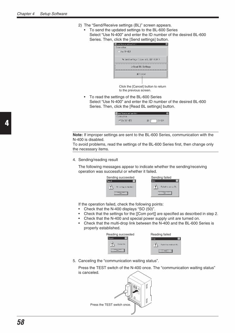
Chapter 4 Setup Software
58
4
2) The “Send/Receive settings (BL)” screen appears.• To send the updated settings to the BL-600 Series
Select “Use N-400” and enter the ID number of the desired BL-600Series. Then, click the [Send settings] button.
• To read the settings of the BL-600 SeriesSelect “Use N-400” and enter the ID number of the desired BL-600Series. Then, click the [Read BL settings] button.
Note: If improper settings are sent to the BL-600 Series, communication with theN-400 is disabled.To avoid problems, read the settings of the BL-600 Series first, then change onlythe necessary items.
4. Sending/reading result
The following messages appear to indicate whether the sending/receivingoperation was successful or whether it failed.
If the operation failed, check the following points:• Check that the N-400 displays “SO (50)”.• Check that the settings for the [[Com port]] are specified as described in step 2.• Check that the N-400 and special power supply unit are turned on.• Check that the multi-drop link between the N-400 and the BL-600 Series is
properly established.
5. Canceling the “communication waiting status”.
Press the TEST switch of the N-400 once. The “communication waiting status”is canceled.
Click the [Cancel] button to returnto the previous screen.
Sending succeeded Sending failed
Reading succeeded Reading failed
Press the TEST switch once.

59
Chapter 4 Setup Software
4
4.4 Reading/Saving/Printing File
This section describes how to read, save, or print settings of a file.
4.4.1 [[Files]] screenThe [[Files]] screen allows the following operation/setting of files (setting data).
4.4.2 Reading a previously saved setting file1. Click the [Open] button.
The “Open Settings file” screen appears.
2. Select a file and click the [OK] button.
The saved file is opened.
[Open] buttonReads a file contain-ing the saved settingsof the BL-600 Series.
[Save] buttonSaves the updatedsettings of the BL-600Series to a file.
[Compare] buttonCompares the filecurrently being editedwith a file that waspreviously saved.
[Print] buttonPrints the setting.
[Version Info] buttonDisplays the version ofthe software.
“Model”Select the model of thebar code reader that willbe used.
[Defaults] buttonResets the edited settings tothe initial (factory) settings.
[OK] button Click [Cancel] to return tothe previous screen.

Chapter 4 Setup Software
60
4
4.4.3 Saving updated settings in a file1. Click the [Save] button. The “Save Settings file” screen appears.
2. Click in the file name entry field and enter a file name.
Up to 8 characters can be used for a file name.
3. Click the [OK] button.
• If the entered file name is illegal, an error message appears and the file isnot saved.In this case, click the [OK] button and repeat steps 1 to 3. See page 67.
• If the file is properly saved, the following message appears.
Reference: If a file saved with a name consisting of only alphanumerics (alphabetsand numbers) is sent to the BL-600 Series, the file name is also sent. In this case,when you read the settings of the BL-600 Series the next time, you can also readthe file name to check the name of the current file of the BL-600 Series. This isconvenient for maintenance.If characters other than alphanumerics are included in a file name, the file name isnot sent to the BL-600 Series because the BL-600 Series cannot recognize them.
[OK] button Click [Cancel] to return to theprevious screen.
Click the [OK] button to return to theinitial screen.

61
Chapter 4 Setup Software
4
4.4.4 Comparing the contents of the file currently being edited with a savedfile
1. Click the [Compare] button. The “Compare Settings file” screen appears.
2. Select a saved file to be compared and click the [OK] button.
The selected saved file is compared with the file currently being edited.
4.4.5 Printing contents of a setting file1. Click the [Print] button. The “Print” screen appears.
2. Specify each item as required.
3. Click the [OK] button to start printing.
Click [Cancel] to return to theprevious screen.
If the settings match If the settings do not match
Click [Cancel] to return to theprevious screen.
[OK] button
[OK] button

Chapter 4 Setup Software
62
4
4.4.6 Resetting the edited settings to the initial (factory) settings1. Click the [Defaults] button.
If you click this button without saving the file currently being edited, a warningmessage appears.
2. To continue the initialization, click the [OK] button.
Note: The [Defaults] button operation is used to initialize the edited settings of thesetup software. The settings on the BL-600 Series cannot be initialized.
4.5 Using Monitor
This setup software provides the “Monitor” program to check if the BL-600 cansend data properly. The “Monitor” program allows you to display the data read bythe BL Series on the host computer’s monitor screen, and also to send a commandfrom the host computer to the BL-600 or BL Series.
4.5.1 Receiving data and checking the resultThe bar code data read with the BL-600 Series can be received with a personalcomputer and checked on the screen.
1. Set the communication parameters of the personal computer according to thoseof the BL-600 Series. See pages 54 and 55.
2. Click on [[Monitor]]. The MONITOR screen will appear.
[OK] button Click [Cancel] to return to theprevious screen.

63
Chapter 4 Setup Software
4
3. Receive the bar code data.
• The bar code data read with the BL-600 Series is displayed on the “Re-ceived Data” field.
• You can also see the history of the previous data (up to 1000 lines) using thescroll bar on the right of the “Received Data” field.
4. Stopping the bar code data display
1) Click the [Stop] button. The name of the button changes to [Start] anddisplay of the received data is stopped.
2) When the [Start] button is clicked, the name of the button changes to [Stop]and display of the received data is restarted.
4.5.2 Command transmission See pages 114 to 128.
1. Set the communication parameters of the personal computer according to thoseof the BL-600 Series. See pages 54 and 55.
2. Click on [[Monitor]]. The MONITOR screen will appear.
Scroll bar
[Stop] button
Click [Quit] to return to theprevious screen.

Chapter 4 Setup Software
64
4
Command buttons
Click [Quit] to return tothe previous screen.
3. Enter the serial communication command in the “Send Command” field ( See
pages 114 to 128.) and press the [ENTER] key on the keyboard. Now, commandscan be sent from a personal computer to the BL-600 Series.
* Use only uppercase characters for the commands.
• Command transmission with the command buttons
Clicking the command buttons on the right side of the screen allows thefollowing commands to be sent to the BL-600 Series.
[TEST1] button: Activates the reading rate check mode.[TEST2] button: Activates the tact check mode.[QUIT] button: Quits the test mode.[LON] button: Starts reading.[LOFF] button: Quits reading.
4. Checking the history of sent commands
Clicking of the “Send Command” field displays the history of the sent com-mands (up to 100 commands).
[Quit] button

65
Chapter 4 Setup Software
4
4.5.3 Starting the test modeThe test mode of the BL-600 Series can be started with a command button.
1. Set the communication parameters of the personal computer according to thoseof the BL-600 Series. See pages 54 and 55.
2. Click on [[Monitor]]. The MONITOR screen will appear.
3. Start the test mode by clicking the [TEST1] or [TEST2] button.
Operation of the BL-600 Series
[TEST1] button: Activates the reading rate check mode.[TEST2] button: Activates the tact check mode.
* You can also start the test mode by typing “TEST1” or “TEST2” (uppercaseonly) in the “Send Command” field and sending it.
4. When the [QUIT] button is clicked, test mode is finished.
* You can also end the test mode by typing “QUIT” in the “Send Command”field and sending it.

Chapter 4 Setup Software
66
4
4.5.4 Changing the scanning widthThe scanning width of the BL-600 Series can be changed with a command button. See page 117.
Note: When the scanning width is changed, the laser beam may not be properlyapplied to the bar codes, resulting in poor readings. Change the scanning widthonly when it is necessary. Thoroughly check that the change did not affect thereading performance.
1. Set the communication parameters of the personal computer according to thoseof the BL-600 Series. See pages 54 and 55.
2. Click on [[Monitor]]. The MONITOR screen will appear.
3. Click the [TEST1] button.
The BL-600 Series enters test mode and emits a laser beam.
4. Specify the starting angle of scanning.
Send the following command.
SDEG a [ENTER] [a: 0 to 400 (Unit: 0.1°)]↑ [*Initial value = 0]
Input from the keyboard
* Specify an appropriate angle by checking the field of the laser beam.
5. Specify the scanning angle.
Send the following command.
WDEG b [ENTER] [b: 400 to 600 (Unit: 0.1°)]↑ [*Initial value = 600]
Input from the keyboard
* Specify an appropriate angle by checking the field of the laser beam.
Clicking the [QUIT] buttonquits the test mode.
[TEST1] button

67
Chapter 4 Setup Software
4
6. When the setting is complete, quit the test mode.
Click the [QUIT] button.
* The changed scanning width is retained even after the BL-600 Series isturned off.
Note 1: The scanning width cannot be specified to exceed the angle range be-tween “c” and “d” (60°).Note 2: The angle specified in the steps above should be used as a guide. If aprecise setting is required, adjust the position of each bar code reader separatelyafter installation.
d
b
60°
a
c
Approx. 60° Approx. 60°
egassemrorrE stnetnoCgnirudsrorrE
putessiatadderetnE“”]KO[.tcerrocni
.tcerrocnisiatadderetneehT.atadtcerrocehtretne-eR
gnirudsrorrEnoitacinummoc
htiwnoitacinummoC“”]KO[.deliaf006-LB
006-LBehthtiwnoitacinummocgnirudrorrE.)sgnittesgnidnesrof( .65egapeeS
006-LBmorftuodaeR“”]KO[.deliaf
006-LBehthtiwnoitacinummocgnirudrorrE.)sgnittesgnidaerrof( .65egapeeS
siledomdeificepsehT“”]KO[.tcerrocni
ehttonsierawtfosputesehtnitesledomehT.detcennocsitahtledomehtsaemas
.24egapeeS
elifsrorrEgnitide
gnirudelifgnisseccA“”]KO[.detcejer
.detresnisiksidyppolfoN.detcetorp-etirwsiksidyppolfehT
.llufsiksidyppolfehT
”]KO[.dnuoftoneliF“eliftcerrocaretnE.tcerrocnisiemanelifehT
.eman .06egapeeS.tcerrocniemaneliF“”]KO[
4.6 List of Error Messages

Chapter 4 Setup Software
68
4
/ / / New setting data [Untitled] / / /
< < Model = BL-600 > > [x] Selected[_] -----------=> Changed
1) Main
[Read mode] [x] Single [_] Multi 1 [_] Multi 2 [_] Multi 3[Data-send] [x] After read [_] At trigger input[Repeat-reading time] [10] x 100 ms[Decoding match count] [2] times[Read error] ERROR [4552524F52][Add Decoding match count] [_] Enable[Add scan count] [_] Enable[Add code type] [_] Enable[Add label orientation] [_] Enable[Add symbology ID.] [_] Enable[Add PMI.] [_] Enable
2) Trigger setup
[Signal type] [x] Level [_] One shot[One shot input time] [10] x 100 ms[Input time] [x] 2 ms [_] 10 ms[State] [x] Normally open [_] Normally close[Command for Trigger ON] LON [4C4F4E][Command for Trigger OFF] LOFF [4C4F4646][Test mode initiated with input ON] [x] OFF [_] Reading-rate check [_] Tact check[Test mode initiated upon power-up] [x] OFF [_] Reading-rate check [_] Tact check[Power-on trigger] [_] Enable
3) Comm Settings–1
[Baud rate] 9600 bps.[data bits] [x] 7 bits [_] 8 bits[Parity] [x] Even [_] Odd [_] None[Stop bits] [x] 1 bit [_] 2 bits[RTS/CTS] [_] Use RTS/CTS handshaking[Multi-drop link(RS-485)] [_] Enable[ID number] No. [1]
4) Comm Settings–2
[Use PLC] [_] Enable[Handshaking] [x] None [_] PASS/RTRY [_] ACK/NAK[Header] [x] None [_] STX [_] ESC [_] Custom[Delimiter] [x] CR [_] CR+LF [_] ETX [_] Custom[Partition mark] : [3A][Intermediate delimiter] , [2C][Checksum] [_] Enable[Send delay time] [0] ms
5) Utility
[Stability LED] [_] Use stability LED[OK/NG output duration] [50] x 10 ms[Preset data] = [no data][Reverse bar code reading] [_] Enable[Quiet zone scale] [7] Times[Decode cancel count] [0][Test SW output] [x] Enable
(1/2)
4.7 Example of Printing from the Setup Software
When “Print” is executed from the setup software, the following data is printed.

69
Chapter 4 Setup Software
4
[Code 1 setup Bar code = CODE39
[Max code length] [32][Min code length] [3][Send start/stop character (*)] [_] Enable[Inspect check-digit [Modulus 43] [_] Enable[Send check-digit] [x] Enable-----Options setup------[Max code length output] [x] Not used [_] Forward [_] Reverse[Effective] [32][Starting] [1][Specify label orientation] [x] Not used [_] Forward [_] Reverse
[Code 2 setup] Bar code = Codabar
[Max code length] [32][Min code length] [3][Start/stop character] [_] Do not send [x] Lower-case [_] Upper-case[Inspect check-digit] [_] Enable[Send check-digit] [x] Enable[Type of check-digit] Modulus 16-----Options setup------[Max code length output] [x] Not used [_] Forward [_] Reverse[Effective] [32][Starting] [1][Specify label orientation] [x] Not used [_] Forward [_] Reverse
[Code 3 setup] Bar code = UPC/EAN
[Read EAN 13(UPC-A)] [x] Enable[Read EAN 8] [x] Enable[Read UPC-E] [x] Enable[No. of UPC-A output] [x] 13 digits [_] 12 digits[Add UPC-E system code 0] [x] Do not add [_] Add-----Options setup-----[Max code length output] [x] Not used [_] Forward [_] Reverse[Effective] [32][Starting] [1][Specify label orientation] [x] Not used [_] Forward [_] Reverse
[Code 4 setup] Bar code = CODE128
[Max code length] [32][Min code length] [1][EAN-128 support] [_] Enable-----Options setup-----[Max code length output] [x] Not used [_] Forward [_] Reverse[Effective] [32][Starting] [1][Specify label orientation] [x] Not used [_] Forward [_] Reverse
Printed: 99/08/07 20:40:28
(2/2)

Chapter 4 Setup Software
70
4


![INDEX []€¦ · Web viewRegency Estates Landlords Handbook 29 LEE LANE, HORWICH, BOLTON, BL6 7AY Tel - 01204 695919 Email – nick@regencyestates.co.uk. I NTRODUCTION Regency Estates](https://img.pdfslide.net/doc/110x75/5fde66a8b38d086a4e78059d/index-web-view-regency-estates-landlords-handbook-29-lee-lane-horwich-bolton.jpg)