Embed Size (px)
Citation preview
Bruker BioSpin
BLA2H500 E
think forw
Amplifier 400500MHz
Operating & Service ManualNard
Versio
n 001MR Spectroscopy

The information in this manual may be altered without notice.
BRUKER BIOSPIN accepts no responsibility for actions taken as a result of use of this manual. BRUKER BIOSPIN accepts no liability for any mistakes contained in the manual, leading to coincidental damage, whether during installation or operation of the instrument. Unauthorised reproduction of manual contents, without written permission from the publishers, or translation into an other language, either the entire manual or a part of it, is forbidden.
This manual describes the units as they are at the date of printing. On request, the manufacturer shall supply circuit diagrams, lists of components, descriptions, calibrating instructions and any other information for use by qualified personnel of the user, in charge of repairing the parts of the unit which have been stated by the manufacturer to be "repairable". Such supply shall in no event constitute permission to modify or repair the units or approval of the same.
All rights reserved for the units, circuits, processes and appellations mentioned herein.
This unit is not designed for any type of use which is not specifically described in this manual. Such use may be hazardous.
This manual was written by
Jacky Schaeffer
This manual was edited and desktop published by
Dominique Wurtz
© October 14, 2009: Bruker BioSpin
Wissembourg, France
P/N: Z31830DWG-Nr: Z4D10534
For further technical assistance on the BLA2H500 E unit, please do not hesitate to contact your nearest BRUKER dealer or contact us directly at:
BRUKER BioSpin 34 rue de l’Industrie F-67166 Wissembourg Cedex France Phone: + 33 388 066 000 Fax: + 33 388 736 820 Email: [email protected] Internet: www.bruker.com

Contents
Contents ............................................................................ 3
1 General Information ........................................................... 51.1 Introduction ........................................................................................ 5
2 Safety .................................................................................. 72.1 Identification Labels ............................................................................ 7
Identifying Plate ............................................................................. 7Manufacturer’s Name Plate ............................................................ 8
2.2 Safety Labels and Symbols ................................................................. 9Warning Signs ............................................................................... 9
Danger ...................................................................................... 9Instruction ................................................................................. 9
3 Installation .........................................................................113.1 Initial Inspection ............................................................................... 11
Mechanical Check ........................................................................ 11Claim for Damage ........................................................................ 11Reshipment and Repackaging Requirements ............................... 11Environment Requirements .......................................................... 12
3.2 Installation Requirements ................................................................. 12Bench Operation .......................................................................... 12
3.3 Power Requirements ........................................................................ 123.4 System Check .................................................................................. 123.5 Initial Turn on Procedure .................................................................. 13
4 Operation .......................................................................... 154.1 Front Panel Description .................................................................... 15
Indicators ..................................................................................... 15Coaxial Connectors ...................................................................... 16Ethernet 10/100 Interface Connector ............................................ 16Device Front View ........................................................................ 17
4.2 Rear Panel Description ..................................................................... 18Device Rear View ........................................................................ 18
5 Technical Description ...................................................... 195.1 System Overview .............................................................................. 195.2 Theory of Operation .......................................................................... 21
RF Path ....................................................................................... 21RF Power Amplifiers ................................................................ 21RF Couplers ............................................................................ 21RF Isolators ............................................................................ 21
Operating & Service Manual Version 001 BRUKER BIOSPIN 3 (45)
Contents
BLA Control Board ....................................................................... 22BLA Extension Board ................................................................... 24Status Led Board ......................................................................... 24BIS Board .................................................................................... 24
6 Servicing the BLA .............................................................256.1 Accessing the BLA Amplifier ............................................................. 256.2 Sub Toolbar Information ................................................................... 26
Device Information (default) ......................................................... 26Amplifier Status ........................................................................... 27
6.3 Sub Toolbar Advanced Operations ................................................... 28Device Information (advanced) .................................................... 28Amplifier Limitations .................................................................... 29Change Limits ............................................................................. 30Routing Information and Setting ................................................... 31
6.4 Sub Toolbar Maintenance ................................................................. 32Device Information (maintenance) ............................................... 32Self-Test & Software Reset .......................................................... 33Firmware Update ......................................................................... 35BIS Content ................................................................................. 36
7 Specifications ...................................................................377.1 Common Characteristics .................................................................. 377.2 General Specifications ..................................................................... 38
Channel H1 and H2 500W Output ................................................ 38
8 Service Information and Maintenance ..............................398.1 Preventive Maintenance of the RF Module on BLA-Type Amplifiers .. 39
Operation .................................................................................... 39
Figures ............................................................................. 41
Tables ............................................................................... 43
4 (45) BRUKER BIOSPIN Operating & Service Manual Version 001
1General Information 1
Introduction 1.1
The BLA2H500 E Amplifier 400-500MHz is a broadband linear pulse power amplifier specifically designed for Magnetic Resonance Imaging (MRI) application for 9,4 to 11,7 Teslas Systems. It is commercialized under the BRUKER BIOSPIN part number W1345508.
It is operated in AB linear class and provides twice 500W and more peak RF power over the frequency range 400-500MHz on the H1 OUT and H2 OUT channel output.
The amplifier is equipped with N-Channel RF LDMOSFETs transistors of the latest generation. The unit can provide full power for any combination of pulse width and duty cycle up to 60ms and 6%.
Its built-in protection circuitry will allow lower power pulses for longer pulse widths and duty-cycles, maintaining a 30W average power on the both channel output.
The electronic protection circuitry has been designed to protect against:
• Excessive power output level (overdrive)
• Excessive pulse repetition rate (over duty-cycle protection)
• Excessive pulse duration (over pulse-width)
• More than 50% reflected RF power (mismatch when VSWR ≥ 6)
• Thermal protection (overheat)
The amplifier is powered by an internal switched power supply assembly that provides the +32VDC for the power amplifiers, in addition to all low level voltages for the system.
The supply is self protected for overcurrent and overvoltage.
The entire unit is housed in a 19", 3U, 520mm rack cabinet.
Operating & Service Manual Version 001 BRUKER BIOSPIN 5 (45)

General Information
6 (45) BRUKER BIOSPIN Operating & Service Manual Version 001
2Safety 2
The BLA2H500 E Amplifier 400-500MHz is in accordance with the standard 61010-1 and with the UL 61010-1 / CSA C22.2 No.61010-1-04 Safety Requirements for Electrical Equipments.
Identification Labels 2.1
Labels are provided to alert operating and service personnel to conditions that may cause personal injury or damage to the equipment from misuse or abuse. Please read the labels and understand their meaning.
Identifying Plate 2.1.1
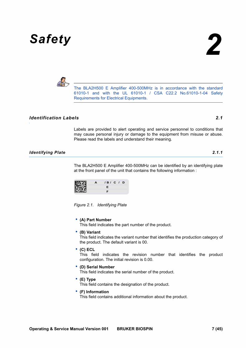
The BLA2H500 E Amplifier 400-500MHz can be identified by an identifying plate at the front panel of the unit that contains the following information :
Figure 2.1. Identifying Plate
• (A) Part Number This field indicates the part number of the product.
• (B) Variant This field indicates the variant number that identifies the production category of the product. The default variant is 00.
• (C) ECL This field indicates the revision number that identifies the product configuration. The initial revision is 0.00.
• (D) Serial Number This field indicates the serial number of the product.
• (E) Type This field contains the designation of the product.
• (F) Information This field contains additional information about the product.
A / / /B C DEF
Operating & Service Manual Version 001 BRUKER BIOSPIN 7 (45)
Safety
Manufacturer’s Name Plate 2.1.2
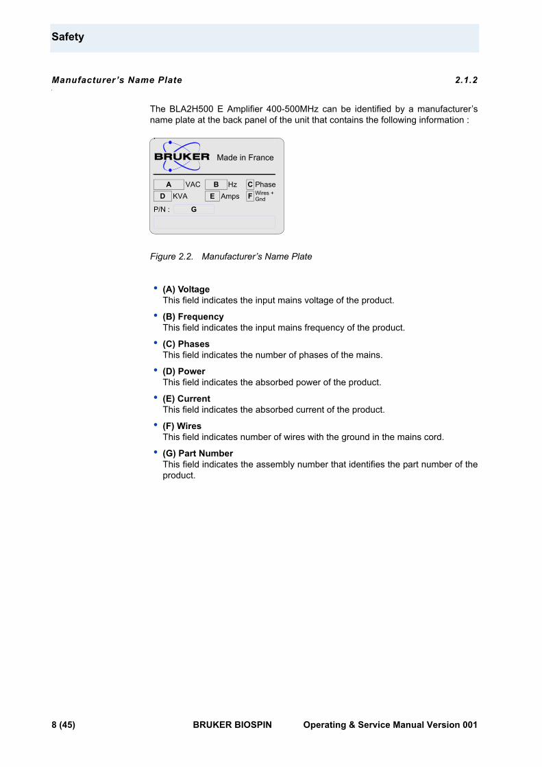
The BLA2H500 E Amplifier 400-500MHz can be identified by a manufacturer’s name plate at the back panel of the unit that contains the following information :
Figure 2.2. Manufacturer’s Name Plate
• (A) Voltage This field indicates the input mains voltage of the product.
• (B) Frequency This field indicates the input mains frequency of the product.
• (C) Phases This field indicates the number of phases of the mains.
• (D) Power This field indicates the absorbed power of the product.
• (E) Current This field indicates the absorbed current of the product.
• (F) Wires This field indicates number of wires with the ground in the mains cord.
• (G) Part Number This field indicates the assembly number that identifies the part number of the product.
Hz
Made in France
VACWires +
A B C PhaseFD KVA GndE Amps
P/N : G
8 (45) BRUKER BIOSPIN Operating & Service Manual Version 001

Safety Labels and Symbols
Safety Labels and Symbols 2.2
Warning Signs 2.2.1
Danger
InstructionOperating personal should not remove RF output cable without turn off the power supply because the RF output can cause serious burns before the "Mismatch" protection is active.
Please disconnect the mains supply before opening to prevent potential hazard such as :
• Electrical shock from power supply
• Contact burns from the RF module and heatsink
• Finger scratch due to the fan assembly on the RF module.
DANGER! Risk of electrical shocks
Throughout this manual, this symbol indicates the possibility of severe personal injury, loss of life or equipment damage if the instructions are not followed.
On the equipment, the symbol also implies a danger and alerts the user.
Operating & Service Manual Version 001 BRUKER BIOSPIN 9 (45)

Safety
10 (45) BRUKER BIOSPIN Operating & Service Manual Version 001
3Installation 3
The installation of the device must be done only by an authorized and qualified technician, in total accordance with the running standards.
BRUKER BIOSPIN assumes no liability for the customer’s failure to comply with these requirements and is therefore not responsible or liable for any injury or damage that occurs as a consequence of non-approved installation.
Initial Inspection 3.1
Mechanical Check 3.1.1
If damage of the shipping cardboard is evident, request the carrier's agent to be present when the instrument is unpacked. Check the equipment for damage and inspect the cabinet and panel surfaces for dents and scratches.
Claim for Damage 3.1.2
If the unit is mechanically damaged or fails to meet specifications upon receipt, notify BRUKER or our representative immediately. Retain the shipping cardboard and packing material for the carriers inspection as well as for subsequent use in returning the unit if necessary.
Reshipment and Repackaging Requirements 3.1.3
Whenever possible, the original cardboard and packing material should be used for reshipment. If the original packing material is not available, wrap the instrument in heavy paper or plastic. Use a strong shipping container. If cardboard is used, it should be at least 200 lbs. test material.
Use shock absorbing material around all sides of the instrument to provide a firm cushion and to prevent movement from inside the container wall on each side. Protect the front panel by means of cardboard spacers inserted between the front panel and the shipping cardboard. Make sure that the instrument cannot move in the container during shipping. Seal the cardboard box with a good grade of shipping tape and mark the container :
"FRAGILE ELECTRONIC INSTRUMENT"
Operating & Service Manual Version 001 BRUKER BIOSPIN 11 (45)
Installation
Environment Requirements 3.1.4
This amplifier is built for inside use only on a maximum elevation of 2000m above sea level (6600 feet).
No specific cooling or ventilation is required.
Be sure that the amplifier has enough area around it so that the free airs flow into and out of the amplifier is not obstructed.
It should, however, be in an environment which conforms to the 5°C - 45°C (41°F - 113°F) thermal specifications, a 80% maximum relative humidity of air and a contamination level of two (means a normal non-conductive contamination, temporary conductivity due to condensation is possible).
Installation Requirements 3.2
No special precautions are necessary. Mount the equipment in an area which is relatively free of vibration, and has sufficient room for cable connections.
The amplifier has a class II installation category.
Bench Operation 3.2.1
The unit can be placed onto a secure flat surface.
Power Requirements 3.3
The BLA2H500 E Amplifier 400-500MHz has a built-in switched power supply. The mains line connector on the rear panel is a CEI 10A.
One Phase Line requirements :
AC input voltage : 208-230VAC Input current max : 4,15A Frequency : 50/60Hz
System Check 3.4
Before applying power for the first time the following items should be checked:
• The AC input voltage 208-230 VAC ± 10% range must be compatible with the power supply.
• An external blanking (gating) pulse must be supplied to the amplifier in order for the unit to function. Ensure that this pulse has a proper level and logic polarity.
• The BLA2H500 E Amplifier 400-500MHz has a nominal input level of +4dBm. Ensure that the system drivers are operating at these levels.
• Output RF loads are connected.
12 (45) BRUKER BIOSPIN Operating & Service Manual Version 001
Initial Turn on Procedure
Initial Turn on Procedure 3.5
The following list describes how to turn on the BLA2H500 E Amplifier 400-500MHz and what should be seen as this occurs.
Before starting this procedure, make sure that you have properly followed the instructions in section "System Check" on page 12.
1. Connect the amplifier to the AC line and turn the line switch to ON.
2. Observe the indicators on the front panel of the amplifier : - The +32V ON LED's will illuminate, - The +15V, -15V and +3,3V ON LED's will illuminate.
3. System is now fully operational.
Operating & Service Manual Version 001 BRUKER BIOSPIN 13 (45)

Installation
14 (45) BRUKER BIOSPIN Operating & Service Manual Version 001

4Operation 4
Front Panel Description 4.1
The BLA2H500 E Amplifier 400-500MHz front panel is provided with 2 x 11 indicators for status monitoring, 6 RF connectors, 1 interface connector and 1 line switch.
Indicators 4.1.1
Normal operation is indicated when following LED's are ON.
Table 4.1. Indicators Assignment
+32V Indicates that the +32V supply is applied.
+15V Indicates that the +15V supply is applied.
-15V Indicates that the -15V supply is applied.
+3,3V Indicates that the +3,3V supply is applied.
Overdrive Indicates when the peak power limit has been reached.
Duty Cycle (D.C.) Indicates when the duty cycle limit has been reached.
Pulse Width (P.W.) Indicates when the pulse width limit has been reached.
Mismatch Indicates when the max. reflected power limit has been reached.
RF POW. FLT Indicates when one of the above limits has been reached.
Overheat Indicates that the thermistor located on the RF module heatsink has sensed excessive heatsink temperature. The amplifier is blanked until an accepable temperature is reached. The function is self-resetting and no maintenance is needed.Indicates also that a fan on the assembly stops turning. The amplifier is blanked until fans are changed.
H500 ON Indicates when the RF Power is present on the H1 channel or H2 channel.
Operating & Service Manual Version 001 BRUKER BIOSPIN 15 (45)
Operation
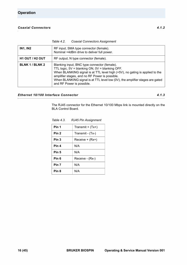
Coaxial Connectors 4.1.2
Table 4.2. Coaxial Connectors Assignment
Ethernet 10/100 Interface Connector 4.1.3
The RJ45 connector for the Ethernet 10/100 Mbps link is mounted directly on the BLA Control Board.
Table 4.3. RJ45 Pin Assignment
IN1, IN2 RF input, SMA type connector (female).Nominal +4dBm drive to deliver full power.
H1 OUT / H2 OUT RF output, N type connector (female).
BLNK 1 / BLNK 2 Blanking input, BNC type connector (female).TTL logic, 5V = blanking ON, 0V = blanking OFF.When BLANKING signal is at TTL level high (+5V), no gating is applied to the amplifier stages, and no RF Power is possible.When BLANKING signal is at TTL level low (0V), the amplifier stages are gated and RF Power is possible.
Pin 1 Transmit + (Tx+)
Pin 2 Transmit - (Tx-)
Pin 3 Receive + (Rx+)
Pin 4 N/A
Pin 5 N/A
Pin 6 Receive - (Rx-)
Pin 7 N/A
Pin 8 N/A
16 (45) BRUKER BIOSPIN Operating & Service Manual Version 001
Front Panel Description
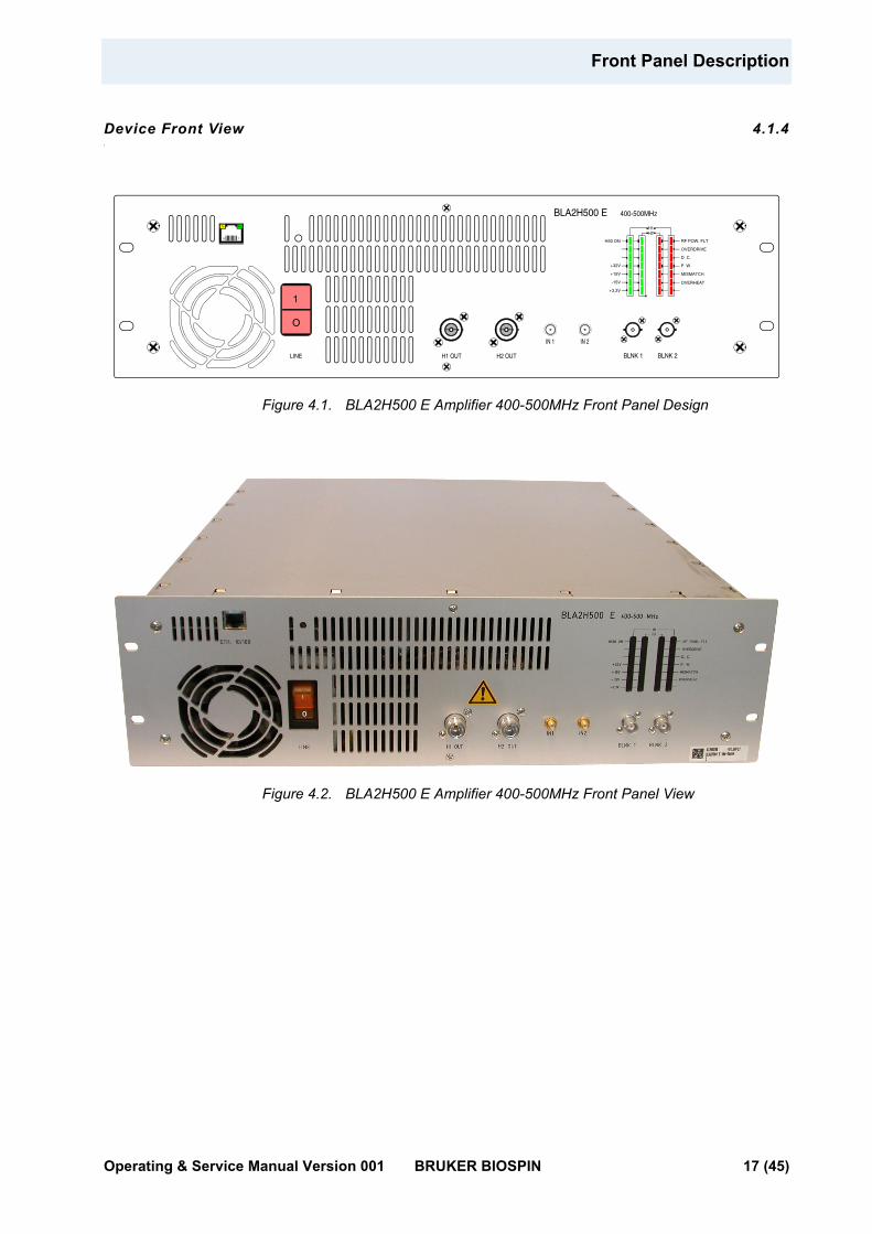
Device Front View 4.1.4
Figure 4.1. BLA2H500 E Amplifier 400-500MHz Front Panel Design
Figure 4.2. BLA2H500 E Amplifier 400-500MHz Front Panel View
1
O
BLA2H500 E 400-500MHz
BLNK 2LINE
IN 1
H2 OUTH1 OUT
H50 ON
+32V
+15V
-15V
+3,3V
RF POW. FLT
OVERHEAT
OVERDRIVE
D. C.
P. W.
MISMATCH
H1H2
Tx Rx
18
IN 2
BLNK 1
Operating & Service Manual Version 001 BRUKER BIOSPIN 17 (45)
Operation
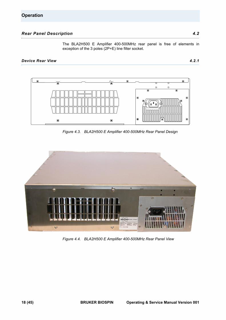
Rear Panel Description 4.2
The BLA2H500 E Amplifier 400-500MHz rear panel is free of elements in exception of the 3 poles (2P+E) line filter socket.
Device Rear View 4.2.1
Figure 4.3. BLA2H500 E Amplifier 400-500MHz Rear Panel Design
Figure 4.4. BLA2H500 E Amplifier 400-500MHz Rear Panel View
18 (45) BRUKER BIOSPIN Operating & Service Manual Version 001
5Technical Description 5
System Overview 5.1
The BLA2H500 E Amplifier 400-500MHz provides :
• Two RF Output of 500W and more on the channel output H1 OUT and H2 OUT, over the full frequency range 400 to 500MHz.
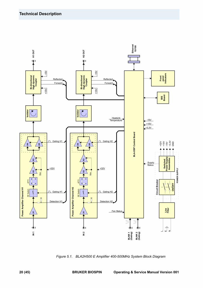
The RF section of the system consists of a linear module BLM2H500-E mounted around a single self-contained Push fan assembly heatsink.
The linear module BLM2H500-E is build with two class AB Power Amplifiers. The amplifier for the channel H1 is located on the top side of the module and the one for the channel H2 is on the bottom side.
The both output channels are connected to the front panel of the BLA2H500 Eeach via an isolator and a bi-directional high dynamic coupler.
The entire system is controlled by a Digital Signal Processing control board, processing information from the amplifier and blanking signal, providing protection from excessive peak power, duty cycle and pulse width for average power, maximum reflected power and heatsink over-temperature.
The DSP control board reads the indentification information of the amplifier (BIS).
Monitoring of fan status, supply status and LED's status is also performed by the control board.
Circuits such as BLAC6 Extension Board 2 Channels and Status LED's board, complete the amplifier assembly.
Operating & Service Manual Version 001 BRUKER BIOSPIN 19 (45)
Technical Description
Figure 5.1. BLA2H500 E Amplifier 400-500MHz System Block Diagram
RF
Switc
hAT
T1
Pow
er A
mpl
ifier
Cha
nnel
H2
Bia
s
A3
A2
A4
A5
A1
RF
Switc
hAT
T1
Pow
er A
mpl
ifier
Cha
nnel
H1
Bia
s
A3
A2
A4
A5
A1
IN 2
GN
D
L N
Line
Filte
rSw
itche
dPo
wer
Sup
ply
Ass
embl
ies
ON
/OFF
Circ
uit B
reak
er
E
POW
ER S
UPP
LY
+3,3
V-1
5V+1
5V+3
2VFr
ont
pane
lin
dica
tors
BIS
Boa
rd
BLA
-DSP
Con
trol
Boa
rd
Supply
+15V
-15V
+3,3V
Status
Fan Status
TemperatureHeatsink
Reflected
ForwardH
2 O
UT 10
/100
Ethe
rnet
+15V
-15V
Detection H1
Gating H1
Gating H1
+32V
Detection H2
+32V
Gating H2
Gating H2
BLN
K 1
(Gat
ing)
BLN
K 2
(Gat
ing)
Bi-d
irect
iona
lH
igh
dyna
mic
Cou
pler
Bi-d
irect
iona
lH
igh
dyna
mic
Cou
pler
H1
OU
T
+15V
-15V
Reflected
Forward
IN 1
Isol
ator
Isol
ator
20 (45) BRUKER BIOSPIN Operating & Service Manual Version 001
Theory of Operation
Theory of Operation 5.2
RF Path 5.2.1
The BLA2H500 E Amplifier 400-500MHz (P/N: W1345508) consists of two class AB power amplifiers.
A nominal input power level of +4dBm produces a rated linear output power of :
• 500W peak for 6% duty cycle at 60ms pulse width maximum on each of the both channel H1 and H2 output.
The unit is also capable of longer pulses for lower average power, up to 30W CW.
RF Power AmplifiersIn the first section of the power amplifiers, the RF input signal is fed directly to a hybrid amplifier and crosses the RF detection path. Then it is conveyed via an AsGa RF Switch to a thermo compensated attenuator (Thermal pad) and two class A drivers to build a nominal 38dB to 40dB gain block.
In this section, only the RF switch requires a control board conditioned gating signal to control the operation of the switching element.
The second section of the power amplifier includes two LDMOSFET transistors.
The circuitry around the transistors consists of complementary input and output transformers and baluns and operates the devices in push-pull.
This section requires a control board conditioned gating signal in order to control the bias gate voltage on the gates of the FETs.
The input-output gain of this section is at nominal 16dB.
The RF power amplifier has a 55dB nominal gain and operates at +32VDC.
RF CouplersThe bi-directional high dynamic couplers on the front panel provide an approximate 1V peak DC signal for full output power and also a peak DC signal for reflected power.
Both signals, forward and reflected, are analyzed by the BLA Control board for monitoring and protection setting.
RF IsolatorsThe RF isolators are built-in to protect the output power transistors from excessive signal reflection. There is a isolator incorporated between each power output and coupler.
Operating & Service Manual Version 001 BRUKER BIOSPIN 21 (45)
Technical Description
BLA Control Board 5.2.2
The BLA Control Board has 3 main functions:
1. Conditions the input blanking (BLNK) signal and delivers it to the above mentioned RF Paths.
2. Allows Ethernet communication with the workstation.
3. Monitor the output characteristics of the amplifier thanks to the DC peak detection of the bi-directional high dynamic coupler. Electronic circuitry processes the detection information and protect the amplifier from overstress like :
• Forward and reflected peak power
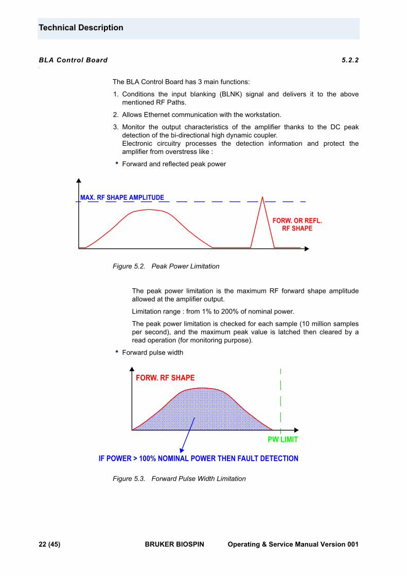
Figure 5.2. Peak Power Limitation
The peak power limitation is the maximum RF forward shape amplitude allowed at the amplifier output.
Limitation range : from 1% to 200% of nominal power.
The peak power limitation is checked for each sample (10 million samples per second), and the maximum peak value is latched then cleared by a read operation (for monitoring purpose).
• Forward pulse width
Figure 5.3. Forward Pulse Width Limitation
MAX. RF SHAPE AMPLITUDE
FORW. OR REFL.RF SHAPE
FORW. RF SHAPE
PW LIMIT
IF POWER > 100% NOMINAL POWER THEN FAULT DETECTION
22 (45) BRUKER BIOSPIN Operating & Service Manual Version 001
Theory of Operation
The pulse width is the lapse of time during which the nominal power can be applied.
Limitation range : from 0.1ms to 512ms.
The pulse width value is updated every 100µs.
• Forward pulse duty cycle
The duty cycle value is the ratio between measured input power during pulse width limitation value divided by duty cycle limitation value and the nominal power during the same time.
For example, if the pulse width limitation is set to 3ms and duty cycle is limited to 10%, then duty cycle value equals the measured input power during 30ms (3ms / 0.1) divided by the nominal power during 30ms.
Limitation range : from 1% to 100%.
The duty cycle value is updated every 100µs.
• Excess of reflected power (Mismatch)
The mismatch value is the ratio between the reflected power value and the forward power value.
Limitation range : from 1% to 100%.
The mismatch value is updated every 100µs.
• Other protections
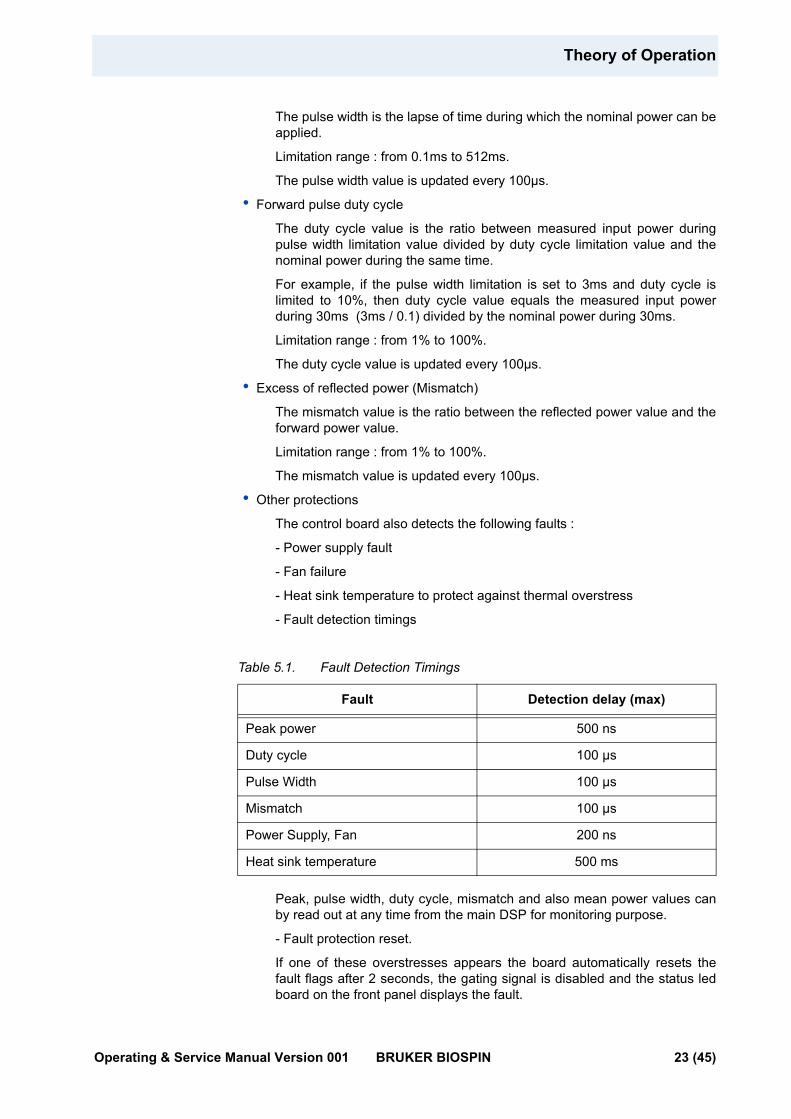
The control board also detects the following faults :
- Power supply fault
- Fan failure
- Heat sink temperature to protect against thermal overstress
- Fault detection timings
Table 5.1. Fault Detection Timings
Peak, pulse width, duty cycle, mismatch and also mean power values can by read out at any time from the main DSP for monitoring purpose.
- Fault protection reset.
If one of these overstresses appears the board automatically resets the fault flags after 2 seconds, the gating signal is disabled and the status led board on the front panel displays the fault.
Fault Detection delay (max)
Peak power 500 ns
Duty cycle 100 µs
Pulse Width 100 µs
Mismatch 100 µs
Power Supply, Fan 200 ns
Heat sink temperature 500 ms
Operating & Service Manual Version 001 BRUKER BIOSPIN 23 (45)
Technical Description
This means, for example, that when a pulse width fault occurs, the amplifier channel is disabled after the detection delay. The side effect is that the fault condition disappears since the channel's output power is null.
After 2 seconds, the channel is switched on and the cycle begins again (unless the channel RF input signal is re-adjusted to meet the power limitations).
BLA Extension Board 5.2.3
This board gives the information to the control board of RF detection.
Status Led Board 5.2.4
The status led board, on the front panel of the amplifier, displays overstress functions, supplies status, and so on, as described in "Indicators" on page 15and "BLA Control Board" on page 22.
BIS Board 5.2.5
The universal BIS board is located on the amplifier case and contains identifications of the amplifier.
Technical help : please contact your local representative.
24 (45) BRUKER BIOSPIN Operating & Service Manual Version 001

6Servicing the BLA 6
The BLA2H500 E Amplifier 400-500MHz provides diagnosis and servicing web pages relies on HTTP, allowing service access with any web browser.
Accessing the BLA Amplifier 6.1
The BLA2H500 E Amplifier 400-500MHz is accessible via the BLA control board with its IP address.
The IP address is given during "cf" by using TOPSPIN 2.xx software on the workstation.
In case of problems :
• Check the RJ45 cabling between amplifier, Ethernet switch and workstation.
• Check the Ethernet switch power.
• Check if the green LED on the amplifier RJ45 connector lights up.
• Check the front panel of the amplifier, LED's indicators +32V, +15V, -15V and +3.3V ON must have lit.
To access the BLA2H500 E Amplifier 400-500MHz, type "ha" in TOPSPIN 2.xx or better and choose the BLA that should be accessed or start your favourite web browser and type the given IP address as URL.
Operating & Service Manual Version 001 BRUKER BIOSPIN 25 (45)
Servicing the BLA
Sub Toolbar Information 6.2
Device Information (default) 6.2.1
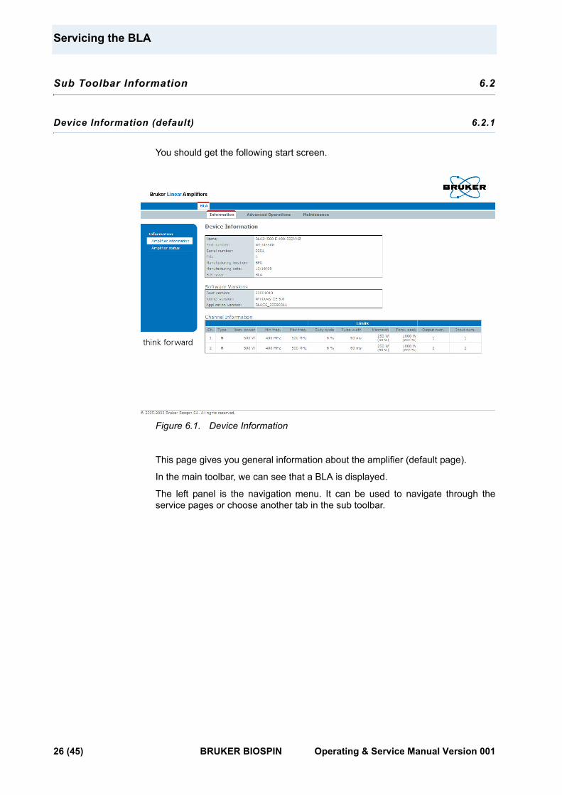
You should get the following start screen.
Figure 6.1. Device Information
This page gives you general information about the amplifier (default page).
In the main toolbar, we can see that a BLA is displayed.
The left panel is the navigation menu. It can be used to navigate through the service pages or choose another tab in the sub toolbar.
26 (45) BRUKER BIOSPIN Operating & Service Manual Version 001
Sub Toolbar Information
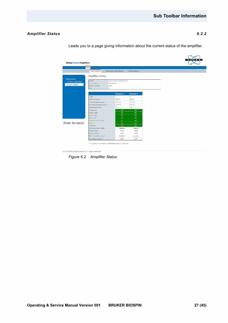
Amplifier Status 6.2.2
Leads you to a page giving information about the current status of the amplifier.
Figure 6.2. Amplifier Status
Operating & Service Manual Version 001 BRUKER BIOSPIN 27 (45)

Servicing the BLA
Sub Toolbar Advanced Operations 6.3
Device Information (advanced) 6.3.1
You should get the following start screen.
Figure 6.3. Device Information
This page gives you general information about the amplifier.
The left panel is the navigation menu. It can be used to navigate through the service pages or choose another tab in the sub toolbar.
28 (45) BRUKER BIOSPIN Operating & Service Manual Version 001
Sub Toolbar Advanced Operations
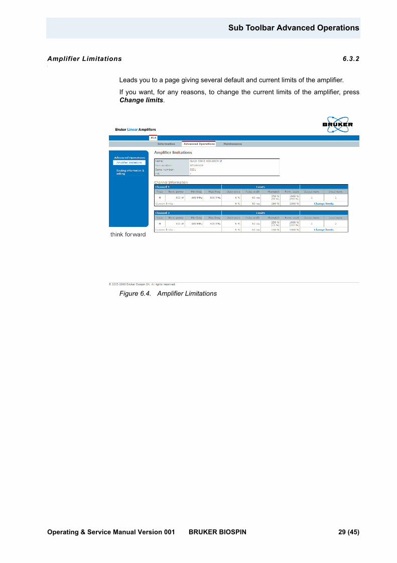
Amplifier Limitations 6.3.2
Leads you to a page giving several default and current limits of the amplifier.
If you want, for any reasons, to change the current limits of the amplifier, press Change limits.
Figure 6.4. Amplifier Limitations
Operating & Service Manual Version 001 BRUKER BIOSPIN 29 (45)
Servicing the BLA
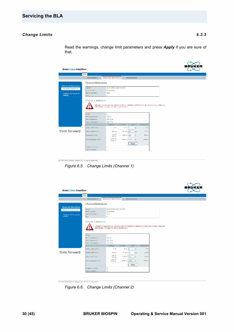
Change Limits 6.3.3
Read the warnings, change limit parameters and press Apply if you are sure of that.
Figure 6.5. Change Limits (Channel 1)
Figure 6.6. Change Limits (Channel 2)
30 (45) BRUKER BIOSPIN Operating & Service Manual Version 001
Sub Toolbar Advanced Operations
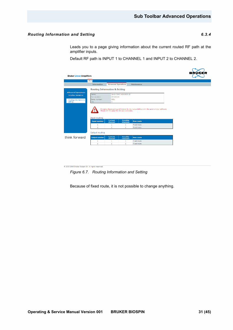
Routing Information and Setting 6.3.4
Leads you to a page giving information about the current routed RF path at the amplifier inputs.
Default RF path is INPUT 1 to CHANNEL 1 and INPUT 2 to CHANNEL 2.
Figure 6.7. Routing Information and Setting
Because of fixed route, it is not possible to change anything.
Operating & Service Manual Version 001 BRUKER BIOSPIN 31 (45)
Servicing the BLA
Sub Toolbar Maintenance 6.4
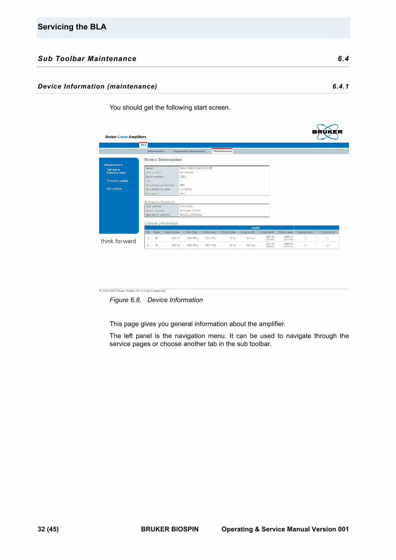
Device Information (maintenance) 6.4.1
You should get the following start screen.
Figure 6.8. Device Information
This page gives you general information about the amplifier.
The left panel is the navigation menu. It can be used to navigate through the service pages or choose another tab in the sub toolbar.
32 (45) BRUKER BIOSPIN Operating & Service Manual Version 001
Sub Toolbar Maintenance
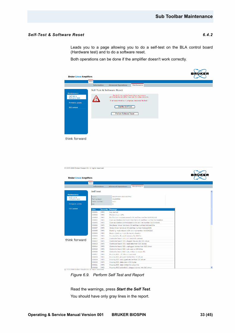
Self-Test & Software Reset 6.4.2
Leads you to a page allowing you to do a self-test on the BLA control board (Hardware test) and to do a software reset.
Both operations can be done if the amplifier doesn't work correctly.
Figure 6.9. Perform Self Test and Report
Read the warnings, press Start the Self Test.
You should have only gray lines in the report.
Operating & Service Manual Version 001 BRUKER BIOSPIN 33 (45)
Servicing the BLA
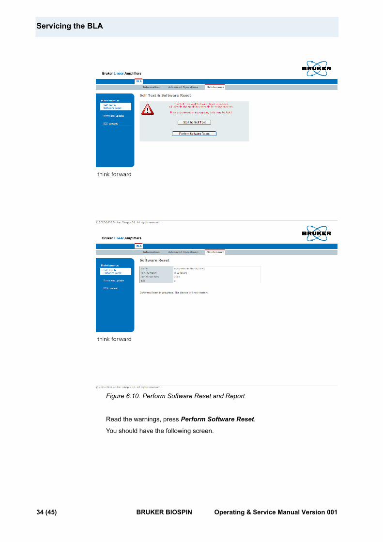
Figure 6.10. Perform Software Reset and Report
Read the warnings, press Perform Software Reset.
You should have the following screen.
34 (45) BRUKER BIOSPIN Operating & Service Manual Version 001
Sub Toolbar Maintenance
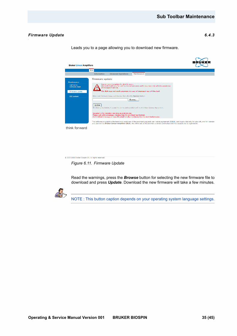
Firmware Update 6.4.3
Leads you to a page allowing you to download new firmware.
Figure 6.11. Firmware Update
Read the warnings, press the Browse button for selecting the new firmware file to download and press Update. Download the new firmware will take a few minutes.
NOTE : This button caption depends on your operating system language settings.
Operating & Service Manual Version 001 BRUKER BIOSPIN 35 (45)
Servicing the BLA
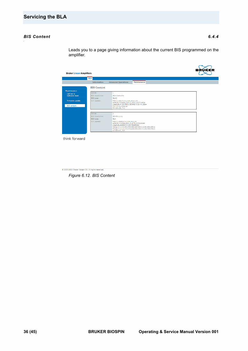
BIS Content 6.4.4
Leads you to a page giving information about the current BIS programmed on the amplifier.
Figure 6.12. BIS Content
36 (45) BRUKER BIOSPIN Operating & Service Manual Version 001
7Specifications 7
Common Characteristics 7.1
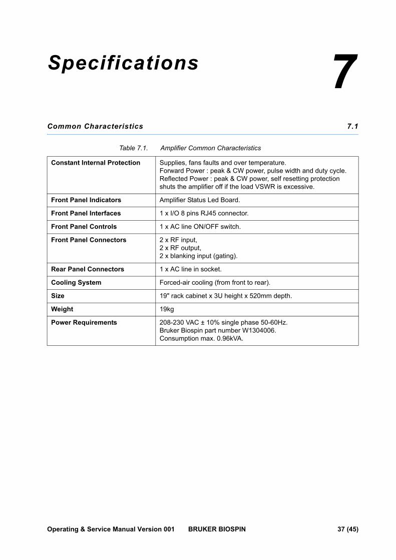
Table 7.1. Amplifier Common Characteristics
Constant Internal Protection Supplies, fans faults and over temperature.Forward Power : peak & CW power, pulse width and duty cycle.Reflected Power : peak & CW power, self resetting protection shuts the amplifier off if the load VSWR is excessive.
Front Panel Indicators Amplifier Status Led Board.
Front Panel Interfaces 1 x I/O 8 pins RJ45 connector.
Front Panel Controls 1 x AC line ON/OFF switch.
Front Panel Connectors 2 x RF input,2 x RF output,2 x blanking input (gating).
Rear Panel Connectors 1 x AC line in socket.
Cooling System Forced-air cooling (from front to rear).
Size 19" rack cabinet x 3U height x 520mm depth.
Weight 19kg
Power Requirements 208-230 VAC ± 10% single phase 50-60Hz.Bruker Biospin part number W1304006.Consumption max. 0.96kVA.
Operating & Service Manual Version 001 BRUKER BIOSPIN 37 (45)
Specifications
General Specifications 7.2
Channel H1 and H2 500W Output 7.2.1
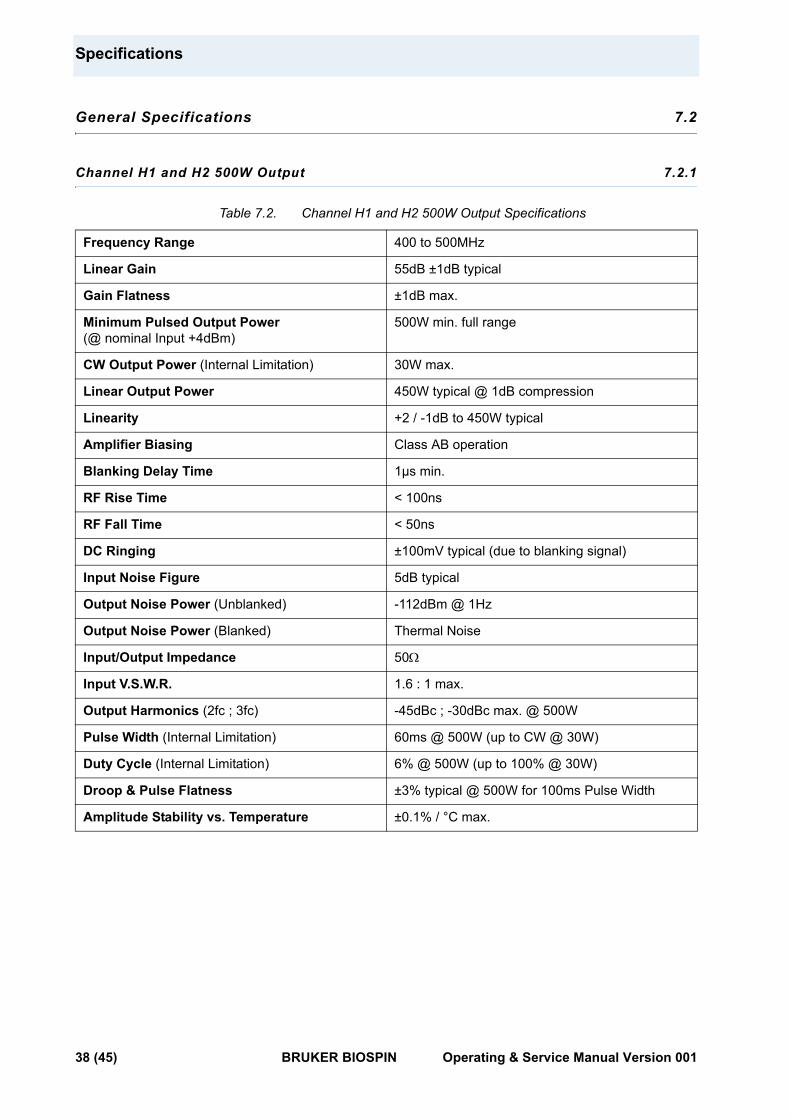
Table 7.2. Channel H1 and H2 500W Output Specifications
Frequency Range 400 to 500MHz
Linear Gain 55dB ±1dB typical
Gain Flatness ±1dB max.
Minimum Pulsed Output Power(@ nominal Input +4dBm)
500W min. full range
CW Output Power (Internal Limitation) 30W max.
Linear Output Power 450W typical @ 1dB compression
Linearity +2 / -1dB to 450W typical
Amplifier Biasing Class AB operation
Blanking Delay Time 1µs min.
RF Rise Time < 100ns
RF Fall Time < 50ns
DC Ringing ±100mV typical (due to blanking signal)
Input Noise Figure 5dB typical
Output Noise Power (Unblanked) -112dBm @ 1Hz
Output Noise Power (Blanked) Thermal Noise
Input/Output Impedance 50Ω
Input V.S.W.R. 1.6 : 1 max.
Output Harmonics (2fc ; 3fc) -45dBc ; -30dBc max. @ 500W
Pulse Width (Internal Limitation) 60ms @ 500W (up to CW @ 30W)
Duty Cycle (Internal Limitation) 6% @ 500W (up to 100% @ 30W)
Droop & Pulse Flatness ±3% typical @ 500W for 100ms Pulse Width
Amplitude Stability vs. Temperature ±0.1% / °C max.
38 (45) BRUKER BIOSPIN Operating & Service Manual Version 001
8Service Information and Maintenance 8
Every intervention on the device must be carried out by an authorized and qualified person. Any failure due to a non-respect of the following instructions will not be attributable to BRUKER BIOSPIN and will not be covered by the guarantee clauses.
Preventive Maintenance of the RF Module on BLA-Type Amplifiers 8.1
The RF module inside BLA's Amplifiers is equipped with a easily extractible PUSH FAN Assembly.
Fan's on assembly have a high reliability and manufacturer gives a expected live time of 70000 hours (8 years) at 25°C and 5 years at 60°C.
Replacement of the assembly could be done in the field when a misfonction of fans is detected by lightning from the OVERHEAT Status Led.
To prevent such a misfonction, a preventive maintenance could be done every 4 years.
This assembly can be ordered on the manufactory BBIO-FR by P/N:
• W1346523 «PUSH FAN ASSEMBLY 6».
Operation 8.1.1
1. Disconnect all cables from the front panel and the supply connector on the rear panel. Remove the amplifier from the NMR console and place it on a secure flat surface.
2. Unscrew and remove the coverage plate from the amplifier.
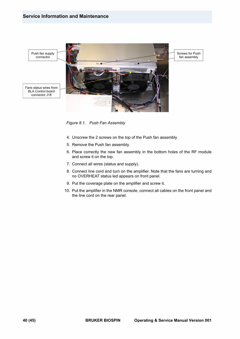
3. Disconnect the 2 wires (red +32V / black GND) being on the RF module dispatch supply connectors and coming from the Push fan assembly. Also disconnect the fan status wires (white) from BLA Control board connector J18.
Operating & Service Manual Version 001 BRUKER BIOSPIN 39 (45)
Service Information and Maintenance
Figure 8.1. Push Fan Assembly
4. Unscrew the 2 screws on the top of the Push fan assembly.
5. Remove the Push fan assembly.
6. Place correctly the new fan assembly in the bottom holes of the RF module and screw it on the top.
7. Connect all wires (status and supply).
8. Connect line cord and turn on the amplifier. Note that the fans are turning and no OVERHEAT status led appears on front panel.
9. Put the coverage plate on the amplifier and screw it.
10. Put the amplifier in the NMR console, connect all cables on the front panel and the line cord on the rear panel.
Push fan supplyconnector
Screws for Pushfan assembly
Fans status wires fromBLA Control board
connector J18
40 (45) BRUKER BIOSPIN Operating & Service Manual Version 001

Figures
1 General Information 5
2 Safety 7Figure 2.1. Identifying Plate .................................................................................... 7Figure 2.2. Manufacturer’s Name Plate ................................................................... 8
3 Installation 11
4 Operation 15Figure 4.1. BLA2H500 E Amplifier 400-500MHz Front Panel Design ...................... 17Figure 4.2. BLA2H500 E Amplifier 400-500MHz Front Panel View ......................... 17Figure 4.3. BLA2H500 E Amplifier 400-500MHz Rear Panel Design ...................... 18Figure 4.4. BLA2H500 E Amplifier 400-500MHz Rear Panel View .......................... 18
5 Technical Description 19Figure 5.1. BLA2H500 E Amplifier 400-500MHz System Block Diagram ................ 20Figure 5.2. Peak Power Limitation ......................................................................... 22Figure 5.3. Forward Pulse Width Limitation ........................................................... 22
6 Servicing the BLA 25Figure 6.1. Device Information .............................................................................. 26Figure 6.2. Amplifier Status ................................................................................... 27Figure 6.3. Device Information .............................................................................. 28Figure 6.4. Amplifier Limitations ............................................................................ 29Figure 6.5. Change Limits (Channel 1) .................................................................. 30Figure 6.6. Change Limits (Channel 2) .................................................................. 30Figure 6.7. Routing Information and Setting .......................................................... 31Figure 6.8. Device Information .............................................................................. 32Figure 6.9. Perform Self Test and Report .............................................................. 33Figure 6.10.Perform Software Reset and Report .................................................... 34Figure 6.11.Firmware Update ................................................................................ 35Figure 6.12.BIS Content ........................................................................................ 36
7 Specifications 37
8 Service Information and Maintenance 39Figure 8.1. Push Fan Assembly ............................................................................ 40
Operating & Service Manual Version 001 BRUKER BIOSPIN 41 (45)

Figures
42 (45) BRUKER BIOSPIN Operating & Service Manual Version 001
Tables
1 General Information 5
2 Safety 7
3 Installation 11
4 Operation 15Table 4.1. Indicators Assignment ......................................................................... 15Table 4.2. Coaxial Connectors Assignment .......................................................... 16Table 4.3. RJ45 Pin Assignment .......................................................................... 16
5 Technical Description 19Table 5.1. Fault Detection Timings ....................................................................... 23
6 Servicing the BLA 25
7 Specifications 37Table 7.1. Amplifier Common Characteristics ....................................................... 37Table 7.2. Channel H1 and H2 500W Output Specifications ................................. 38
8 Service Information and Maintenance 39
Operating & Service Manual Version 001 BRUKER BIOSPIN 43 (45)

Tables
44 (45) BRUKER BIOSPIN Operating & Service Manual Version 001

Operating & Service Manual Version 001 BRUKER BIOSPIN 45 (45)
End of Document

© B
ruke
r B
ioS
pin
Z318
30
Bruker BioSpin Group
Bruker BioSpin,
your solution partner
Bruker BioSpin provides a world class, marketleadingrange of analysis solutions for your life and materialsscience needs.
![Digital Laser Sensor ]Amplifier-separated] LS-400 SERIES · LS SRIS 254 Guide Amplifier Built-in-Amplifier-separated LS LS FIBER SENSORS LASER SENSORS PHOTOELECTRIC SENSORS MICRO](https://img.pdfslide.net/doc/110x75/5f895c9c3456a569b428f831/digital-laser-sensor-amplifier-separated-ls-400-series-ls-sris-254-guide-amplifier.jpg)

![Ultra-slim Photoelectric Sensor [Amplifier Built-in]EX …EX-10 SERIES Ver.2 314 Guide Amplifier Built-in Power Supply Built-in Amplifier-separated CX-400 CY-100 EX-10 EX-20 EX-30](https://img.pdfslide.net/doc/110x75/5fc4f42222b52e70b4230047/ultra-slim-photoelectric-sensor-amplifier-built-inex-ex-10-series-ver2-314-guide.jpg)


![Compact Photoelectric Sensor [Amplifier Built-in] CX-400 ...Amplifier Built-in Power Supply Built-in Amplifier-separated C-400 CY-100 E-10 E-20 E-30 E-40 C-440 E-30 E-500 M-W R-LS200](https://img.pdfslide.net/doc/110x75/5f0279117e708231d4046f04/compact-photoelectric-sensor-amplifier-built-in-cx-400-amplifier-built-in.jpg)