Embed Size (px)
Citation preview
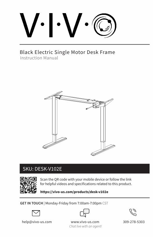
Black Electric Single Motor Desk Frame
Scan the QR code with your mobile device or follow the link for helpful videos and specifications related to this product.
Instruction Manual
https://vivo-us.com/products/desk-v102e
SKU: DESK-V102E
[email protected] www.vivo-us.com 309-278-5303Chat live with an agent!
GET IN TOUCH | Monday-Friday from 7:00am-7:00pm CST

2
If you do not understand these directions, or if you have any doubts about the safety of the installation, please call a qualified technician. Check carefully to make sure there are no missing or defective parts. Improper installation may cause damage or serious injury. Do not use this product for any purpose that is not explicitly specified in this manual and do not exceed weight capacity. We cannot be liable for damage or injury caused by improper mounting, incorrect assembly, or inappropriate use.
WARNING!
PACKAGE CONTENTS
A (x1)Telescopic Crossbar
B (x1)Sync Rod
C (x1)Cable Management
Tray
D (x2)Foot
E (x2)Side Bracket
F (x1)AC Adapter
G (x2)Hook
H (x1)Motorized Leg
I (x1)Leg
J (x1)Power Cable
K (x1)Controller
ELECTRICAL SAFETY INSTRUCTIONSTHIS PRODUCT IS POWERED BY ELECTRICITY. IN ORDER TO AVOID BURNS, FIRE AND ELECTRIC SHOCK, PLEASE READ THE FOLLOWING INSTRUCTIONS CAREFULLY.
• DO NOT CLEAN PRODUCT WHILE POWER IS CONNECTED.
• DO NOT DISASSEMBLE OR REPLACE COMPONENTS WHILE POWER IS CONNECTED.
• NEVER OPERATE THE SYSTEM WITH A DAMAGED CORD OR PLUG. PLEASE CONTACT YOUR
SELLER TO REPLACE DAMAGED PARTS.
• NEVER OPERATE SYSTEM IN DAMP ENVIRONMENTS OR IF ANY ELECTRICAL COMPONENTS HAVE
MADE CONTACT WITH LIQUIDS.
• ALTERATIONS OF THE GIVEN POWER UNIT ARE NOT ALLOWED.
• OUTDOOR USE IS PROHIBITED.
WARNING: CHOKING HAZARDSMALL PARTS - NOT FOR CHILDREN UNDER 3 YEARS. ADULT SUPERVISION IS REQUIRED.
S-A (x16)M6x12mm
Bolt
S-B (x10)7/8” Screw
S-C (x2)3/4” Screw
S-D (x4)M4x6mm
Screw
S-E (x3)Cable Clip
S-F (x8)Rubber Pad
S-G (x1)Allen Wrench
S-H (x3)Soft Pad

3
176lbs(79.8 kg)
DO NOT EXCEED WEIGHT CAPACITY.Failure to do so may result in serious injury.
ASSEMBLY STEPS
STEP 1
Loosen the two set screws on the telescopic crossbar (A) using the Allen Wrench (S-G). Adjust the crossbar length to suit the desktop. Retighten all screws. NOTE: Make sure adjusted length of the telescopic crossbar is no more than 61" (155cm).
TOOLS NEEDED
Phillips Screwdriver
STEP 2
Attach the telescopic crossbar to the legs (H, I) as shown using M6x12mm bolts (S-A), and tighten with the Allen Wrench (S-G).
Drill
NOTE: Insert all necessary screws into holes before tightening.
4
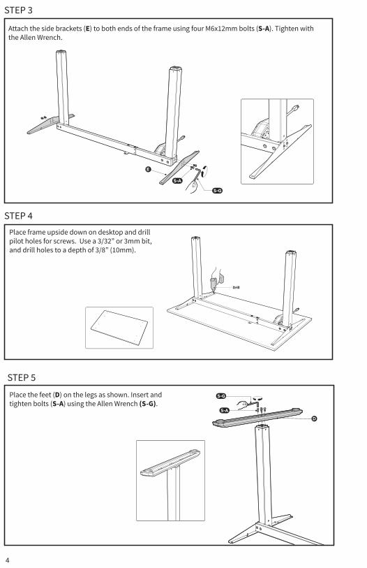
STEP 3
STEP 4
STEP 5
Place frame upside down on desktop and drill pilot holes for screws. Use a 3/32” or 3mm bit, and drill holes to a depth of 3/8” (10mm).
Place the feet (D) on the legs as shown. Insert and tighten bolts (S-A) using the Allen Wrench (S-G).
Attach the side brackets (E) to both ends of the frame using four M6x12mm bolts (S-A). Tighten with the Allen Wrench.

5
STEP 6
STEP 7Attach hooks (G) to cable management tray (C) using M4x6mm screws (S-D) with a Phillips screwdriver. Hang the tray onto the telescopic crossbar and tighten knobs to secure.
Position the frame upright. Loosen the knobs on the sync rod (B) and extend the hex shaft. Insert hex shaft into the leg (I), making sure the metal retaining ring makes contact with the leg. While holding the hex shaft with one hand, extend sync rod onto the spline shaft of the motorized leg. Retighten knob.
CAUTION: To avoid injury, at least two people should turn the frame upright.
OPTIONAL: Remove paper backing from soft pads (S-H) and stick them to the inside and top of hooks (G).
S-H
G

6
STEP 8
STEP 9
STEP 10
Connect the AC adapter (F) and motorized leg to the controller (K). Connect the power cable (J) to the AC adapter.
Remove the protective film from the adhesive rubber pads (S-F). Position the rubber pads on the side brackets and telescopic crossbar as shown.
If you are using a VIVO desktop, Refer to the manual that came with your desktop.
If you are not using a VIVO desktop, place the desktop on the frame, and secure the desktop using the ⅞” screws (S-B).
7
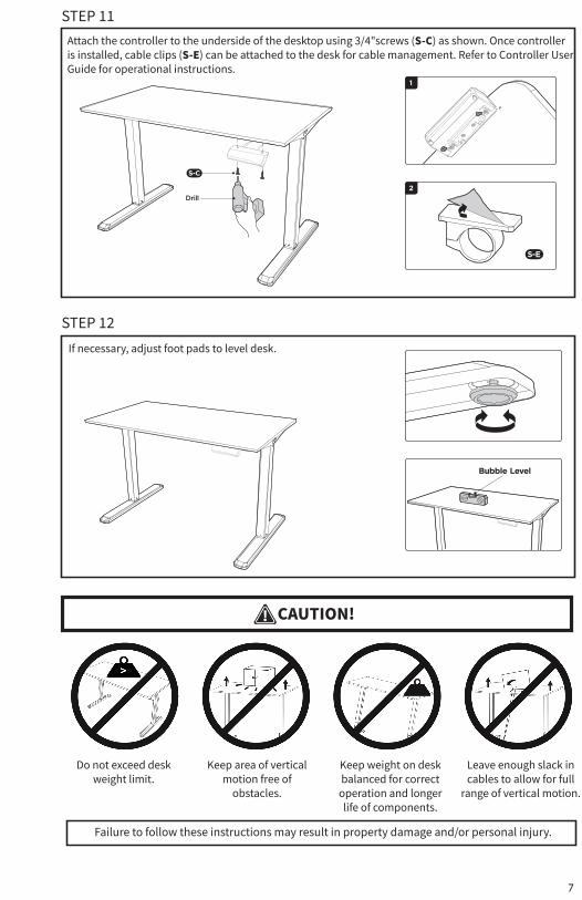
STEP 11
STEP 12
Attach the controller to the underside of the desktop using 3/4"screws (S-C) as shown. Once controller is installed, cable clips (S-E) can be attached to the desk for cable management. Refer to Controller User Guide for operational instructions.
If necessary, adjust foot pads to level desk.
CAUTION!
Failure to follow these instructions may result in property damage and/or personal injury.
Do not exceed desk weight limit.
Keep area of vertical motion free of
obstacles.
Keep weight on desk balanced for correct
operation and longer life of components.
Leave enough slack in cables to allow for full
range of vertical motion.
LAST UPDATED: 09/17/2021REV5.3
Open Monday - Friday 7:00am - 7:00pm CST, our dedicated support team can offer immediate assistance with rapid response times. If any parts are received damaged or defective, please contact us. We are happy to replace parts to ensure you have a fully functioning product.
FOR MORE VIVO PRODUCTS, CHECK OUT OUR WEBSITE AT: www.vivo-us.com
[email protected] AVG. RESPONSE TIME (within office hrs): 1HR 8M - 23% within < 15m - 38% within < 30m - 61% within < 1hr - 83% within < 2hr - 92% within < 3hr
Love your new VIVO setup and want to share? Tag us in your photo! @vivo_us
AVG. RESOLUTION TIME (within office hrs): < 15 M www.vivo-us.comChat live with an agent!
AVG. RESOLUTION TIME (within office hrs): 5M 4S 309-278-5303