Embed Size (px)
Citation preview

Blackfin Timers
Independent timers build into the processor
Watchdog Timer is a major part of Lab. 2 (Code provided to you to use)

04/19/23Timer Control
Copyright M. Smith, ECE, University of Calgary, Canada 2 / 31
Timers available on Blackfin
Watchdog timer – Hardware Reference 15-49 Core timer – Hardware Reference 15-45 General purpose timers 15-1
Pulse Width Modulation Pulse Width Count and Capture External Event
Application of timers to provide code safety and improved version of UseFixedTimeASM( )
Introduction to timer interrupts

04/19/23Timer Control
Copyright M. Smith, ECE, University of Calgary, Canada 3 / 31
Basic concept – watchdog timer
Your code is on an embedded system that is running in the field
Something goes unexpectedly wrong with your program, and one piece of code (a subroutine) keeps running, and running and runningOther parts of the system self-destruct as
there are no control signals send to themFix this issue with “WatchDog Timer”

04/19/23Timer Control
Copyright M. Smith, ECE, University of Calgary, Canada 4 / 31
WatchDogTimer Demonstrate (code provided) Lab 2 Task 1
int main( ) {SetUpWatchDogTimerASM( ); // Subroutine names are modifiedStartWatchDogTimerASM( ); // in Lab. 2ResetWatchDogTimerASM( );
for ( ; ; ) { // For-ever loopCriticalTask1( );ResetWatchDogTimerASM( ); CriticalTask2( );ResetWatchDogTimerASM( );CriticalTask3( );ResetWatchDogTimerASM( );
}}
If any task hangs up (does NOT return in time to Reset the WatchDog Timer) then the system can be made to reboot, or send error message etc.HANGS UP – because an expected external signal does not arrivebecause of equipment failure (SW5 connection “broken” in Lab. 2 Task 1)

04/19/23Timer Control
Copyright M. Smith, ECE, University of Calgary, Canada 5 / 31
Watchdog Timer Operation

04/19/23Timer Control
Copyright M. Smith, ECE, University of Calgary, Canada 6 / 31
Example code -- Setting the CORETIMER registers
_SetUpWatchDogTimerASM__Fv:P0.H = hi(WDOG_CNT)P0.L = lo(WDOG_CNT) // Get the address into P0
// Put 0x08000000 into R1;R1.L = 0x0000; How long is 0x0800 0000 ticks?R1.H = 0x0800;[P0] = R1; // Watchdog Count Register and Watchdog Register

04/19/23Timer Control
Copyright M. Smith, ECE, University of Calgary, Canada 7 / 31
Better Code (other code did not work as we had not read the manual)
_SetUpWatchDogTimerASM__Fv:P0.H = hi(WDOG_CTL)P0.L = lo(WDOG_CTL) // Get the address into P0
// Put 0x0AD0 into R1.L;R1.L = 0x0AD0;W[P0] = R1; // Watchdog control register – disableSSYNC; // System synchronize – Count read/write ops.
P0.H = hi(WDOG_CNT)P0.L = lo(WDOG_CNT) // Get the address into P0
// Put 0x08000000 into R1;R1.L = 0x0000;R1.H = 0x0800;[P0] = R1; // Watchdog Count Register and Watchdog Register

04/19/23Timer Control
Copyright M. Smith, ECE, University of Calgary, Canada 8 / 31
Watchdog Status Register WDOG_STAT

04/19/23Timer Control
Copyright M. Smith, ECE, University of Calgary, Canada 9 / 31
My actual working code for L2 Task 1
NOTE: WDOG_CTL bit 15
is a W1C bit
Write one to clearmeans Write one to make 0
NOT 0x0AD6 but 0x8AD6
to clear bit 15 (W1C)

04/19/23Timer Control
Copyright M. Smith, ECE, University of Calgary, Canada 10 / 31
Starting the watchdog timer
_StartWatchDogTimerASM__Fv:P0.H = hi(WDOG_CTL)P0.L = lo(WDOG_CTL) // Get the address into P0
// Put 0x0000 into R1.L; Will force a “RESET EVENT”R1.L = 0x0000;W[P0] = R1; // Watchdog control register – counter enabled
ssync;
04/19/23Timer Control
Copyright M. Smith, ECE, University of Calgary, Canada 11 / 31
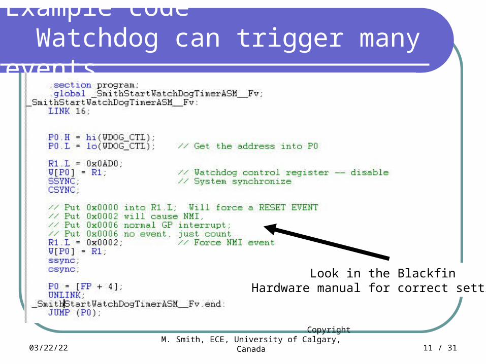
Example code Watchdog can trigger many events
Look in the BlackfinHardware manual for correct settings

Lab. 2 “Flight control” using Watchdog based security
InitFlashASM( ); // Set up the Flash memory – Lab. 1
InitFlashPortASM( ); // Set up Flash LED port – Lab. 1
WriteFlashLEDASM(0); // Clear LED panel – Lab. 1
StopCycleCounterASM( ); // Stop and then reset cycle counter
ResetCycleCounterASM( ); // -- Assignment 3
WatchDogTimerHowled = 0;
ActivateWatchDogTimer( );
while (WatchDogTimerHowled != 1) {
ResetWatchDogTimer( );
GoControlTheAeroPlane( );
CheckIfCrewAreAwake( );
}
StopWatchDogTimer( ); // Should never get here unless Watch Dog Timer 'Howled
WriteFlashLEDASM(0); – Lab. 1
CrewErrorOccurred( );
04/19/23Timer Control
Copyright M. Smith, ECE, University of Calgary, Canada 12 / 31

04/19/23Timer Control
Copyright M. Smith, ECE, University of Calgary, Canada 13 / 31
Watchdog video game

04/19/23Timer Control
Copyright M. Smith, ECE, University of Calgary, Canada 14 / 31
ResetWatchDogTimerASM( ); Practice for Post Lab. 1 Quiz
TAKE-HOME EXERCISE You write the required code – base on standard
Blackfin Assembly language Stub
_ResetWatchDogTimerASM:
My original version – 24 lines of assembly code.
However, I then re-read the manual – resetting the timer can be done in 4 lines of code excluding LINK / UNLINK code

04/19/23Timer Control
Copyright M. Smith, ECE, University of Calgary, Canada 15 / 31
Temperature Sensor -- Lab 3 Q – How can you time “High” time?
ANALOG DEVICESTMP03
Temperature Sensor
+5V
GROUND
SIGNAL TO BLACKFIN -- hook into PF8. Check using the same “when switch SW1 pressed, when released” code as in Lab. 1
HIGH LOW

04/19/23Timer Control
Copyright M. Smith, ECE, University of Calgary, Canada 16 / 31
A C++ version of code (interval counter) Develop a routine UseUpFixedAmountTimeCPP( ) that uses up a fixed
amount of time Use ReadLEDASM( ) to find when input signal goes high When input goes high, call this Interval Counter routine Keep calling the Interval counter until the input goes low Count how many times this routine must be called from main( ) while
the temperature signal is HIGH
Could be constructed using “for-loop” constructvoid UseUpFixedAmoutTimeCPP(unsigned long int timeToUse) {
unsigned short int counter = 0;
for (int num = 0; num <= timeToUse; num ++) {counter = counter; // Waste time
} // Spin the wheels on the processor Post Lab. 1 Question – how would you use ReadLEDASM( ) to wait until the input
signal goes high – Do in either C++ or assembly code.
04/19/23Timer Control
Copyright M. Smith, ECE, University of Calgary, Canada 17 / 31
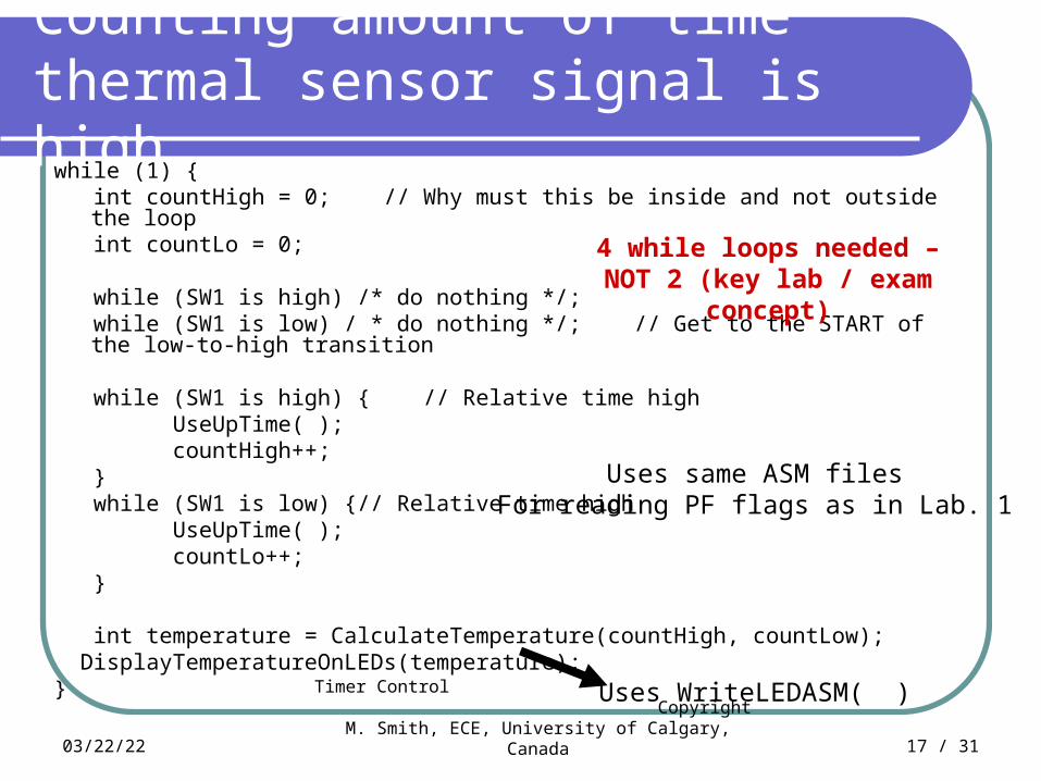
Counting amount of time thermal sensor signal is high
while (1) { int countHigh = 0; // Why must this be inside and not outside the loop int countLo = 0;
while (SW1 is high) /* do nothing */; while (SW1 is low) / * do nothing */; // Get to the START of the low-to-high transition
while (SW1 is high) { // Relative time high UseUpTime( ); countHigh++; } while (SW1 is low) {// Relative time high UseUpTime( ); countLo++; }
int temperature = CalculateTemperature(countHigh, countLow); DisplayTemperatureOnLEDs(temperature);}
Uses same ASM filesFor reading PF flags as in Lab. 1
Uses WriteLEDASM( )
4 while loops needed – NOT 2 (key lab / exam concept)
04/19/23Timer Control
Copyright M. Smith, ECE, University of Calgary, Canada 18 / 31
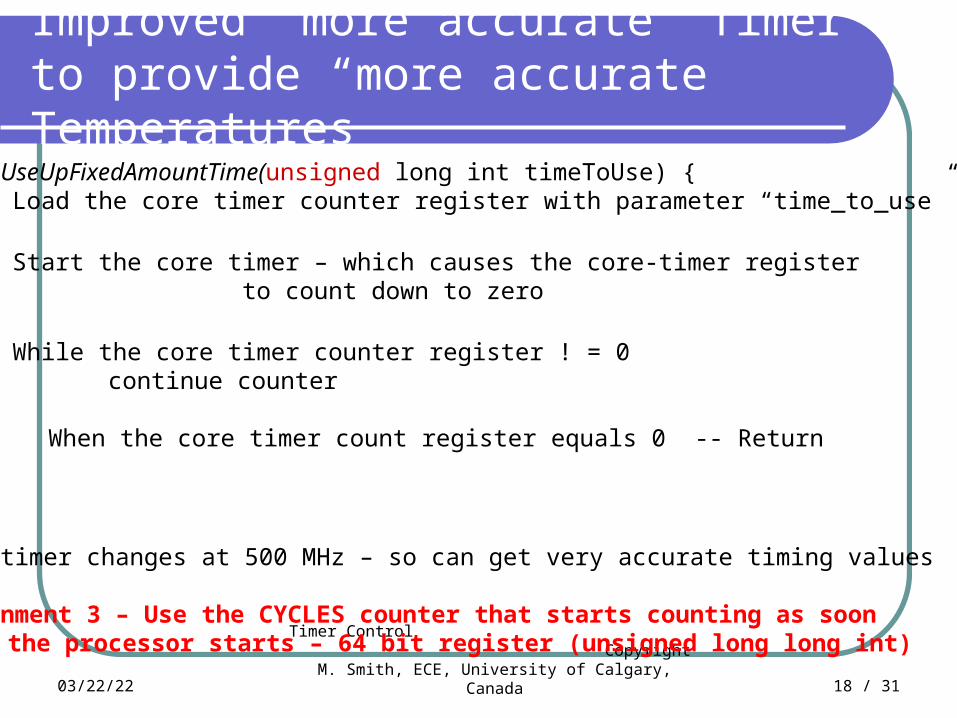
Improved “more accurate” Timer to provide “more accurate” Temperatures
void UseUpFixedAmountTime(unsigned long int timeToUse) {1. Load the core timer counter register with parameter “time_to_use”
2. Start the core timer – which causes the core-timer register to count down to zero
3. While the core timer counter register ! = 0continue counter
4. When the core timer count register equals 0 -- Return
}
Core timer changes at 500 MHz – so can get very accurate timing values
Assignment 3 – Use the CYCLES counter that starts counting as soonas the processor starts – 64 bit register (unsigned long long int)

04/19/23Timer Control
Copyright M. Smith, ECE, University of Calgary, Canada 19 / 31
Core Timer
You set Core timer register TSCALE to 0 (decrement by 0 + 1)You set register TPERIOD to 0x2000You set register TCOUNT to 0x4000You enable timer using control register TCNTL
TCOUNT is decreased by 1 until it reaches 0 (0x4000 system clock ticks)When TCOUNT reaches 1, interrupt is caused andTCOUNT is reloaded with TPERIOD (0x2000) – counts down again

04/19/23Timer Control
Copyright M. Smith, ECE, University of Calgary, Canada 20 / 31
TCOUNT and TPERIOD registers

04/19/23Timer Control
Copyright M. Smith, ECE, University of Calgary, Canada 21 / 31
TSCALE and TCNTL registers

04/19/23Timer Control
Copyright M. Smith, ECE, University of Calgary, Canada 22 / 31
Two new instructions
The INTERRUPT mask contains information (bits set or clear) about which devices are allowed to interrupt the processor
CLI Rx Save a copy of the “INTERRUPT” mask into data
register Rx and then clear the mask (block all interrupts)
STI Rx Copy the bit pattern from data register Rx into the
“INTERRUPT” mask, effectively reactivating all the devices that were allowed to interrupt the processor

04/19/23Timer Control
Copyright M. Smith, ECE, University of Calgary, Canada 23 / 31
void UseUpFixedAmoutTimeASM (unsigned long int timeToUse) - 1
Stop interrupts -- Why is this neededCLI R2; // Clear interrupts -- re-enable interrupts STI R2;
Stop the timer by changing the bits in the timer control registerP0.H = hi(TCNTL)P0.L = lo(TCNTL) // Get the address into P0R1 = 0;[P0] = R1;SSYNC;
Load the core timer counter register with parameter “time_to_use (R0)”P0.H = hi(TCOUNT)P0.L = lo(TCOUNT) // Get the address into P0[P0] = R0;SSYNC;
Start the core timer by changing the bits in the timer control registerP0.H = hi(TCNTL)P0.L = lo(TCNTL) // Get the address into P0R1 = 3;[P0] = R1;SSYNC;

04/19/23Timer Control
Copyright M. Smith, ECE, University of Calgary, Canada 24 / 31
void UseUpFixedAmoutTime (unsigned long int timeToUse) - 2
Stop interruptsStop the timerLoad the core timer counter register with parameter “time_to_use”Start the core timer
P0.H = hi(TCNTL)P0.L = lo(TCNTL) // Get the address into P0R1 = 3; // Bit pattern %0000 0000 0000 0011[P0] = R1;SSYNC;
While the core timer counter register ! = 0 continueP0.H = hi(TCOUNT)P0.L = lo(TCOUNT) // Get the address into P0SSYNC // Necessary or not?
TIMER_LOOP:R0 = [P0]; // Keep reading the timer counterCC = R0 == 0; // TIMER COUNTER IS VOLATILEIF !CC JUMP TIMER_LOOP
DE-ACTIVATE TIMERREACTIVATE INTERRUPTS – Old values stored in R2RETURN

04/19/23Timer Control
Copyright M. Smith, ECE, University of Calgary, Canada 25 / 31
void UseUpFixedAmoutTime (unsigned long int timeToUse) - 3
While the core timer counter register ! = 0 continueP0.H = hi(TCOUNT)P0.L = lo(TCOUNT) // Get the address into P0SSYNC // Necessary or not?
TIMER_LOOP:R0 = [P0]; // Read the timer counterCC = R0 == 0;IF !CC JUMP TIMER_LOOP
DE-ACTIVATE TIMER // You provide the required code
REACTIVATE INTERRUPTS – Old values stored in R2
RETURN

04/19/23Timer Control
Copyright M. Smith, ECE, University of Calgary, Canada 26 / 31
Problem -- CODE IS “WAITING” and uses up processor power uselessly
While the core timer counter register ! = 0 continueP0.H = hi(TCOUNT)P0.L = lo(TCOUNT) // Get the address into P0SSYNC // Necessary or not?
TIMER_LOOP:R0 = [P0]; // Read the timer counterCC = R0 == 0;IF !CC JUMP TIMER_LOOP
Here the processor is waiting, which means that the processor can’t becalculating other values (computer graphics) or servicing other requests
Fixed by using interrupts to do the counting in the background
Perhaps there are no other values to calculate. In that case we need to put the processor in a low power mode, and then wake it up
Fixed with IDLE instruction and then wake-up enable register

04/19/23Timer Control
Copyright M. Smith, ECE, University of Calgary, Canada 27 / 31
Concepts of interrupt code
Task 1 – file 1volatile int foo_flag = 8;
int main( ) {SetUpTimerInterrupts(ISR_count);StartTimerInterrupts( );while (foo_flag != 0) {
WriteLEDASM(foo_flag);DoSomething Complicated( );
} StopTimerInterrupts();}
Task 2 – file 2 (C++ or ASM)
extern volatile int foo_flag;
SPECIAL C++ CODE NEEDED TOTell “C++” that I am not a function or
subroutine that is called within the program. I am an ISR – interrupt service routine and proud of it. I can happen at any time because of an outside external signal
????declare??? ISR_count( ) {foo_flag--;
Tell the timer that the interrupt has been serviced
}

04/19/23Timer Control
Copyright M. Smith, ECE, University of Calgary, Canada 28 / 31
How it is supposed to work
First task 1 (main( ) ) – startsSets up the timer so that it will cause an interruptWhen this interrupt starts – task 1 will stop, task 2 will start
start doing some processing – spend NO time looking at the timer
NOTE – if the ISR – interrupt service routine – does not happen (because external hardware not working) then task 1 will never stop
When Task 1 stops – turn off the interrupts

04/19/23Timer Control
Copyright M. Smith, ECE, University of Calgary, Canada 29 / 31
Task 2 and Task 1 in this code(Not Lab. 2 Tasks 1 and 2)
Task 1 and Task 2 communicate via the “volatile foo_flag” variable – “message”
Every time the timer counts down to zeroThe TCOUNTER register is reloaded with
TPERIOD register valueThe timer counts down againAn interrupt is issued and latched

04/19/23Timer Control
Copyright M. Smith, ECE, University of Calgary, Canada 30 / 31
Unanswered questions
1. What does “volatile” mean?2. Why will “optimized code” probably
not work if volatile is not used?3. How do you tell C++ that this
function is an ISR and not a standard function?
4. Why do you need to tell C++ that this function is an ISR and not a standard function?
5. What is the difference (in coding) between an ISR and a standard function?
6. How does an interupt get latched, why and where?
7. Why do I have to tell the timer that the interrupt has been serviced, and how do I do it?
Task 2 – file 2 (C++ or ASM)
extern volatile int foo_flag;
Tell “C++” that I am not a function but I am an ISR – interrupt service routine
????declare as ISR??? ISR_count( ) {foo_flag--;
Tell the timer that the interrupt has been serviced
}
04/19/23Timer Control
Copyright M. Smith, ECE, University of Calgary, Canada 31 / 31
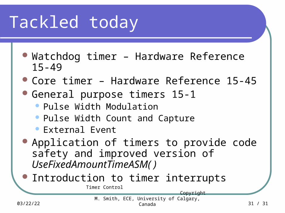
Tackled today
Watchdog timer – Hardware Reference 15-49 Core timer – Hardware Reference 15-45 General purpose timers 15-1
Pulse Width Modulation Pulse Width Count and Capture External Event
Application of timers to provide code safety and improved version of UseFixedAmountTimeASM( )
Introduction to timer interrupts

04/19/23Timer Control
Copyright M. Smith, ECE, University of Calgary, Canada 32 / 31
Information taken from Analog Devices On-line Manuals with permission http://www.analog.com/processors/resources/technicalLibrary/manuals/
Information furnished by Analog Devices is believed to be accurate and reliable. However, Analog Devices assumes no responsibility for its use or for any infringement of any patent other rights of any third party which may result from its use. No license is granted by implication or otherwise under any patent or patent right of Analog Devices. Copyright Analog Devices, Inc. All rights reserved.

04/19/23Timer Control
Copyright M. Smith, ECE, University of Calgary, Canada 33 / 31
Watchdof concepts
WHAT I WANTED TO DO
WHAT I DID
WHAT YOU WILL DOIN ASSEMBLY CODE(Task 2 is for Midterm Exam practice)