Embed Size (px)
Citation preview

Blackfin/SHARC® USB EZ-Extender®
Manual
Revision 1.0, February 2009
Part Number 82-000224-01
Analog Devices, Inc.One Technology WayNorwood, Mass. 02062-9106 a

Copyright Information© 2009 Analog Devices, Inc., ALL RIGHTS RESERVED. This docu-ment may not be reproduced in any form without prior, express written consent from Analog Devices, Inc.
Printed in the USA.
DisclaimerAnalog Devices, Inc. reserves the right to change this product without prior notice. Information furnished by Analog Devices is believed to be accurate and reliable. However, no responsibility is assumed by Analog Devices for its use; nor for any infringement of patents or other rights of third parties which may result from its use. No license is granted by impli-cation or otherwise under the patent rights of Analog Devices, Inc.
Trademark and Service Mark NoticeThe Analog Devices logo, Blackfin, SHARC, VisualDSP++, and EZ-Extender are registered trademarks of Analog Devices, Inc. EZ-Board is a trademark of Analog Devices, Inc.
All other brand and product names are trademarks or service marks of their respective owners.

Regulatory Compliance The Blackfin/SHARC USB EZ-Extender is designed to be used solely in a laboratory environment. The board is not intended for use as a consumer end product or as a portion of a consumer end product. The board is an open system design, which does not include a shielded enclosure and therefore may cause interference to other electrical devices in close prox-imity. This board should not be used in or near any medical equipment or RF devices.
The Blackfin/SHARC USB EZ-Extender is currently being processed for certification that it complies with the essential requirements of the Euro-pean EMC directive 89/336/EEC amended by 93/68/EEC and therefore carries the “CE” mark.
This evaluation system contains ESD (electrostatic discharge) sensitive devices. Electrostatic charges readily accumulate on the human body and equipment and can discharge without detection. Permanent damage may occur on devices subjected to high-energy discharges. Proper ESD precau-tions are recommended to avoid performance degradation or loss of func-tionality. Store unused boards in the protective shipping package.

CONTENTS
PREFACE
Product Overview ......................................................................... viii
Purpose of This Manual .................................................................. ix
Intended Audience .......................................................................... ix
Manual Contents ............................................................................. x
What’s New in This Manual ............................................................. x
Technical or Customer Support ....................................................... xi
Supported Products ......................................................................... xi
Product Information ...................................................................... xii
Notation Conventions ................................................................... xiii
BLACKFIN/SHARC USB EZ-EXTENDER INTERFACES
Blackfin/SHARC USB EZ-Extender Setup .................................... 1-2
USB Software ......................................................................... 1-3
USB 2.0 Interface ......................................................................... 1-3
BLACKFIN/SHARC USB EZ-EXTENDER HARDWARE REFERENCE
System Architecture ...................................................................... 2-2
Jumper Settings ............................................................................. 2-3
Blackfin/SHARC USB EZ-Extender Manual v
CONTENTS
USB Chip Select Jumper (JP1) ................................................ 2-4
USB IRQ Jumper (JP2) ........................................................... 2-4
USB Soft Reset Jumper (JP3) .................................................. 2-4
BLACKFIN/SHARC USB EZ-EXTENDER BILL OF MATERIALS
BLACKFIN/SHARC USB EZ-EXTENDER SCHEMATIC
Title Page ..................................................................................... B-1
Expansion Connector ................................................................... B-2
USB Interface ............................................................................... B-3
INDEX
vi Blackfin/SHARC USB EZ-Extender Manual
PREFACE
Thank you for purchasing the Blackfin/SHARC USB EZ-Extender®,
Analog Devices, Inc. extender board to the EZ-Board™ evaluation system for the ADSP-BF518F, ADSP-BF526 Blackfin®, and ADSP-21469 SHARC® processors.Blackfin processors are embedded processors that support a Media Instruction Set Computing (MISC) architecture. This architecture is the natural merging of RISC, media functions, and digital signal processing characteristics towards delivering signal processing performance in a microprocessor-like environment.
SHARC processors are based on a 32-bit super Harvard architecture that includes a unique memory architecture comprised of two large on-chip, dual-ported SRAM blocks coupled with a sophisticated IO processor, which gives a SHARC processor the bandwidth for sustained high-speed computations. SHARC processors represents today’s de facto standard for floating-point processing, targeted toward premium audio applications.
The EZ-Board and Blackfin/SHARC USB EZ-Extender are designed to be used in conjunction with the VisualDSP++® development environ-ment. VisualDSP++ offers a powerful programming tool with new flexibility that significantly decreases the time required to port software code to a processor, reducing time-to-market.
To learn more about Analog Devices development software, go to http://www.analog.com/processors/tools/.
Blackfin/SHARC USB EZ-Extender Manual vii
Product Overview
Product OverviewThe Blackfin/SHARC USB EZ-Extender is a separately sold extender board that plugs onto the expansion interface of the ADSP-BF518F, ADSP-BF526, and ADSP-21469 EZ-Board evaluation systems. The extender board aids the design and prototyping phases of the ADSP-BF518F, ADSP-BF526, and ADSP-21469 processor targeted applications.
The board extends the capabilities of the evaluation system by providing a connection between the asynchronous memory bus of the Black-fin/SHARC processor and a USB 2.0 device.
The following is a list of the Blackfin/SHARC USB EZ-Extender interfaces.
• USB 2.0 interface:
PLX Technology NET2272 device
USB driver and application code
• No power supply required: derives power from the EZ-Board
• CE certified
Before using any of the interfaces, follow the setup procedure in “Black-fin/SHARC USB EZ-Extender Setup” on page 1-2.
Example programs are available to demonstrate capabilities of the Black-fin/SHARC USB EZ-Extender board.
viii Blackfin/SHARC USB EZ-Extender Manual

Preface
Purpose of This Manual The Blackfin/SHARC USB EZ-Extender Manual provides instructions for installing the product hardware (board). The text describes operation and configuration of the board components. Finally, a schematic and a bill of materials are provided as a reference for future designs.
Intended AudienceThe primary audience for this manual is a programmer who is familiar with Analog Devices processors. This manual assumes that the audience has a working knowledge of the appropriate processor architecture and instruction set. Programmers who are unfamiliar with Analog Devices processors can use this manual, but should supplement it with other texts (such as the Hardware Reference and Instruction Set Reference) that describe your target architecture.
Programmers who are unfamiliar with VisualDSP++ or EZ-Board evalua-tion software should refer to the ADSP-BF518F, ADSP-BF526, or ADSP-21469 EZ-Board Evaluation System Manual, VisualDSP++ online Help, and user’s or getting started guides. For locations of these docu-ments, refer to “Product Information”.
Blackfin/SHARC USB EZ-Extender Manual ix

Manual Contents
Manual ContentsThe manual consists of:
• Chapter 1, “Blackfin/SHARC USB EZ-Extender Interfaces” on page 1-1.Provides basic board information.
• Chapter 2, “Blackfin/SHARC USB EZ-Extender Hardware Refer-ence” on page 2-1.Provides information on the hardware aspects of the board.
• Appendix A, “Blackfin/SHARC USB EZ-Extender Bill Of Materi-als” on page A-1.Provides a list of components used to manufacture the EZ-Extender board.
• Appendix B, “Blackfin/SHARC USB EZ-Extender Schematic” on page B-1.Provides the resources to allow EZ-Board board-level debugging or to use as a reference design.
What’s New in This Manual This is the first edition of the Blackfin/SHARC USB EZ-Extender Manual.
x Blackfin/SHARC USB EZ-Extender Manual

Preface
Technical or Customer SupportYou can reach Analog Devices, Inc. Customer Support in the following ways:
• Visit the Embedded Processing and DSP products Web site athttp://www.analog.com/processors/technicalSupport
• E-mail tools questions [email protected]
• E-mail processor questions [email protected] (World wide support)
[email protected] (Europe support)
[email protected] (China support)
• Phone questions to 1-800-ANALOGD
• Contact your Analog Devices, Inc. local sales office or authorized distributor
• Send questions by mail to:Analog Devices, Inc.
One Technology Way
P.O. Box 9106
Norwood, MA 02062-9106
USA
Supported ProductsThe Blackfin/SHARC USB EZ-Extender is designed as an extender board to the ADSP-BF518F, ADSP-BF526, and ADSP-21469 EZ-Board evalua-tion systems.
Blackfin/SHARC USB EZ-Extender Manual xi
Product Information
Product InformationProduct information can be obtained from the Analog Devices Web site, VisualDSP++ online Help system, and a technical library CD.
• The Analog Devices Web site, www.analog.com, provides informa-tion about a broad range of products—analog integrated circuits, amplifiers, converters, and digital signal processors.
To access a complete technical library for each processor family, go to http://www.analog.com/processors/technical_library. When locating your manual title, note a possible errata check mark next to the title that leads to the current correction report against the manual.
• Online documentation comprises the VisualDSP++ Help system, software tools manuals, hardware tools manuals, processor manu-als, Dinkum Abridged C++ library, and FLEXnet License Tools software documentation. You can search easily across the entire VisualDSP++ documentation set for any topic of interest.
• The technical library CD contains seminar materials, product highlights, a selection guide, and documentation files of processor manuals, VisualDSP++ software manuals, and hardware tools man-uals. To order the technical library CD, go to http://www.analog.com/processors/technical_library, navi-gate to the manuals page for your processor, click the request CD check mark, and fill out the order form.
xii Blackfin/SHARC USB EZ-Extender Manual

Preface
Notation ConventionsText conventions used in this manual are identified and described as follows.
Example Description
Close command (File menu)
Titles in reference sections indicate the location of an item within the VisualDSP++ environment’s menu system (for example, the Close command appears on the File menu).
{this | that} Alternative required items in syntax descriptions appear within curly brackets and separated by vertical bars; read the example as this or that. One or the other is required.
[this | that] Optional items in syntax descriptions appear within brackets and sepa-rated by vertical bars; read the example as an optional this or that.
[this,…] Optional item lists in syntax descriptions appear within brackets delimited by commas and terminated with an ellipse; read the example as an optional comma-separated list of this.
.SECTION Commands, directives, keywords, and feature names are in text with letter gothic font.
filename Non-keyword placeholders appear in text with italic style format.
Note: For correct operation, ...A Note provides supplementary information on a related topic. In the online version of this book, the word Note appears instead of this symbol.
Caution: Incorrect device operation may result if ...Caution: Device damage may result if ... A Caution identifies conditions or inappropriate usage of the product that could lead to undesirable results or product damage. In the online version of this book, the word Caution appears instead of this symbol.
Warning: Injury to device users may result if ... A Warning identifies conditions or inappropriate usage of the product that could lead to conditions that are potentially hazardous for the devices users. In the online version of this book, the word Warning appears instead of this symbol.
Blackfin/SHARC USB EZ-Extender Manual xiii
Notation Conventions
xiv Blackfin/SHARC USB EZ-Extender Manual

1 BLACKFIN/SHARC USB EZ-EXTENDER INTERFACES
This chapter provides the setup procedures for both the Blackfin/SHARC
USB EZ-Extender and EZ-Board (ADSP-BF518F, ADSP-BF526, or ADSP-21469) and describes the interfaces the extender supports.The information is presented in the following order.
• “Blackfin/SHARC USB EZ-Extender Setup” on page 1-2
• “USB 2.0 Interface” on page 1-3
Blackfin/SHARC USB EZ-Extender Manual 1-1

Blackfin/SHARC USB EZ-Extender Setup
Blackfin/SHARC USB EZ-Extender SetupIt is very important to set up all components of the system containing the Blackfin/SHARC USB EZ-Extender, then apply power to the system. The following procedure is recommended for correct setup.
Power your system after these steps are completed:
1. Read the applicable design interface section in this chapter—the text provides an overview of the interface capabilities.
2. Read “System Architecture” on page 2-2 to understand physical connections of the extender board. For detailed information, refer to “Blackfin/SHARC USB EZ-Extender Schematic” on page B-1.
3. Set the jumpers on the Blackfin/SHARC USB EZ-Extender board. Use the block diagram in Figure 2-1 on page 2-2 in conjunction with “Jumper Settings” on page 2-3.
4. Set the switches and jumpers on the EZ-Board. If not already, familiarize yourself with the EZ-Board documentation and sche-matic drawings (see “Product Information”).
Compare the expansion interface signals of the Blackfin/SHARC USB EZ-Extender board with the EZ-Board signals to ensure there is no contention. For example, it may be necessary to disable other devices connected to the expansion interface of the processor and disable peripherals on the EZ-Board.
5. Install the Blackfin/SHARC USB EZ-Extender on the EZ-Board via the high speed expansion interface.
1-2 Blackfin/SHARC USB EZ-Extender Manual

Blackfin/SHARC USB EZ-Extender Interfaces
USB SoftwareFor information about USB software, refer to the USB Software Readme.txt file located in the <install_path>\Blackfin\Examples\USB EZ-EXTENDER or <install_path>\214xx\Examples\USB EZ-EXTENDER VisualDSP++ directory.
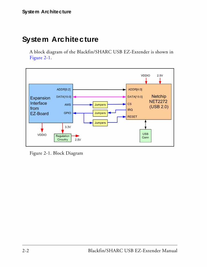
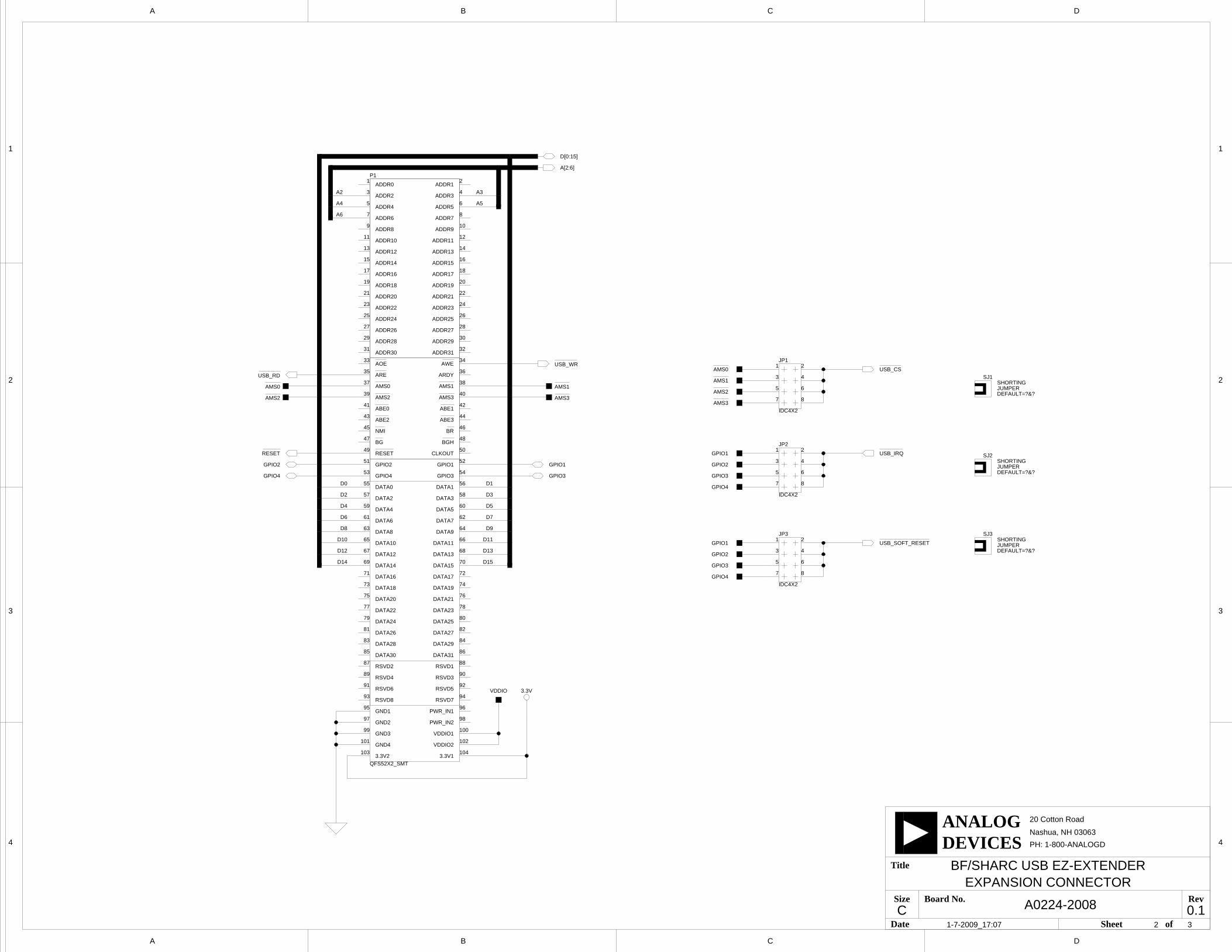
USB 2.0 InterfaceThe Blackfin/SHARC USB EZ-Extender enables a connection between a USB 2.0 chip and Blackfin/SHARC processor without any other pro-grammable logic. The PLX Technology’s NET2272 controller ties directly to the asynchronous memory bus of the Blackfin or SHARC processor. You can read from and write to the USB 2.0 controller by addressing the named memory bank directly.
You can reset the NET2272 controller by asserting LOW one of the four GPIO signals of the expansion interface. Refer to the appropriate EZ-Board manual to learn how the GPIO signals connect to the processor.
The USB IRQ signal of the NET2272 controller connects to one of the four GPIO signals on the expansion interface. Refer to the appropriate EZ-Board document to learn how the GPIO signals connect to the processor.
The USB CS signal of the NET2272 controller connects to one of the four AMS signals on the expansion interface. Refer to the appropriate EZ-Board manual to learn how the AMS signals connect to the processor.
The jumper settings required for each of the respective EZ-Boards are described in the USB Software Readme.txt file located in the <install_path>\Blackfin\Examples\USB EZ-EXTENDER or
Blackfin/SHARC USB EZ-Extender Manual 1-3
USB 2.0 Interface
<install_path>\214xx\Examples\USB EZ-EXTENDER VisualDSP++ direc-tory. The readme file describes the USB software, source code, drivers, and explains how to run a USB-based application.
1-4 Blackfin/SHARC USB EZ-Extender Manual
2 BLACKFIN/SHARC USB EZ-EXTENDER HARDWARE REFERENCE
This chapter describes the hardware design of the Blackfin/SHARC USB
EZ-Extender.The following topics are covered.
• “System Architecture” on page 2-2Describes the board configuration and explains how the board components interface with the processor and EZ-Board.
• “Jumper Settings” on page 2-3Describes the on-board configuration jumpers.
Blackfin/SHARC USB EZ-Extender Manual 2-1
System Architecture
System ArchitectureA block diagram of the Blackfin/SHARC USB EZ-Extender is shown in Figure 2-1.
Figure 2-1. Block Diagram
2-2 Blackfin/SHARC USB EZ-Extender Manual

Blackfin/SHARC USB EZ-Extender Hardware Reference
Jumper SettingsBefore using the Blackfin/SHARC USB EZ-Extender, follow the setup procedure in “Blackfin/SHARC USB EZ-Extender Setup” on page 1-2.
Figure 2-2 shows the locations of all jumper headers. A two-pin jumper can be placed on the respective jumper header for different functionality. The following sections describe all possible jumper settings and associated functionality.
Figure 2-2. Jumper Locations
Blackfin/SHARC USB EZ-Extender Manual 2-3

Jumper Settings
USB Chip Select Jumper (JP1)The USB chip select jumper (JP1) connects an AMS signal from the EZ-Board to the chip select input on the NET2272 controller. The AMS0–
3 signals are available. By default, the jumper is installed on pins 7 and 8, which connect AMS3 to the chip select signal.
USB IRQ Jumper (JP2)The USB IRQ jumper (JP2) connects a general-purpose IO signal from the EZ-Board to the interrupt output on the NET2272 controller. The GPIO1–4 signals are available. By default, the jumper is installed on pins 1 and 2, which connect GPIO1 to the interrupt signal.
USB Soft Reset Jumper (JP3)The soft reset jumper (JP3) connects a general-purpose signal from the EZ-Board to the reset input on the NET2272 controller. GPIO1–4 are available. By default, the jumper is installed on pins 7 and 8, which con-nect GPIO4 to the reset signal.
2-4 Blackfin/SHARC USB EZ-Extender Manual

A BLACKFIN/SHARC USB EZ-EXTENDER BILL OF MATERIALS
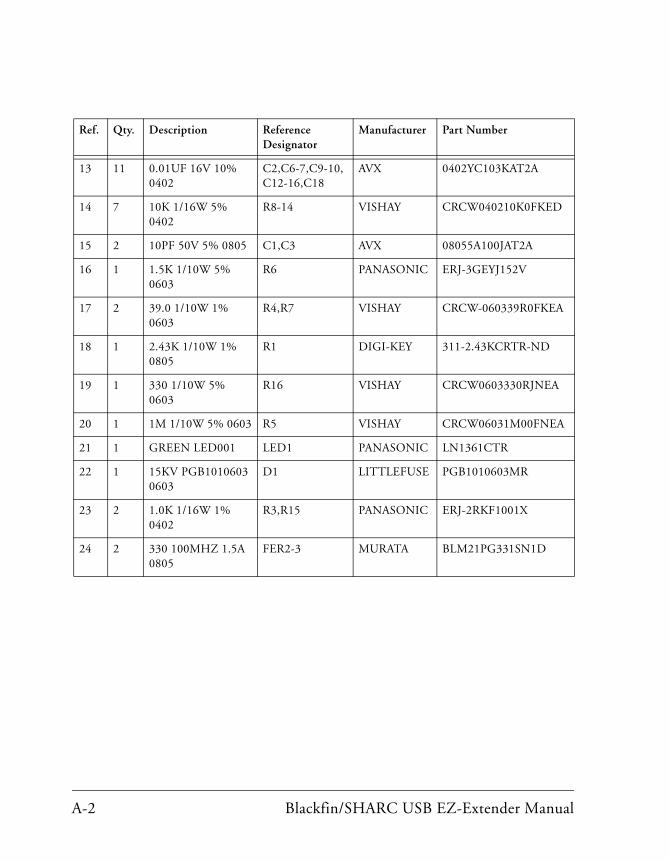
The bill of materials corresponds to “Blackfin/SHARC USB EZ-Extender
Schematic” on page B-1.Ref. Qty. Description Reference Designator
Manufacturer Part Number
1 1 SN74LVC1G08 SOT23-5
U2 TI SN74LVC1G08DBVR
2 1 NET2272 TQFP64 U1 NET CHIP NET2272REV1A-LF
3 1 30MHZ OSC010 Y1 ECLIPTEK E2SAA10-30.000M
4 1 ADP130AUJZ-2.5 TSOT5
VR1 ANALOG DEVICES
ADP130AUJZ-2.5-R7
5 3 IDC 2PIN_JUMPER_SHORT
SJ1-3 DIGI-KEY S9001-ND
6 1 USB_MINI-B 5PIN CON046
P2 MOLEX 54819-0519
7 3 IDC 4X2 IDC4X2 JP1-3 SULLINS GEC04DAAN
8 1 QFS 52x2 QFS52x2_SMT
P1 SAMTEC QFS-052-04.25-L-D-A
9 2 1UF 16V 10% 0805 C4-5 KEMET C0805C105K4RAC TU
10 1 47.0K 1/10W 1% 0805
R2 VISHAY CRCW080547K0FKEA
11 1 42 100MHZ 4A 0805
FER1 DIGI-KEY 587-1768-2-ND
12 3 10UF 6.3V 10% 0805
C8,C11,C17 AVX 08056D106KAT2A
Blackfin/SHARC USB EZ-Extender Manual A-1
13 11 0.01UF 16V 10% 0402
C2,C6-7,C9-10,C12-16,C18
AVX 0402YC103KAT2A
14 7 10K 1/16W 5% 0402
R8-14 VISHAY CRCW040210K0FKED
15 2 10PF 50V 5% 0805 C1,C3 AVX 08055A100JAT2A
16 1 1.5K 1/10W 5% 0603
R6 PANASONIC ERJ-3GEYJ152V
17 2 39.0 1/10W 1% 0603
R4,R7 VISHAY CRCW-060339R0FKEA
18 1 2.43K 1/10W 1% 0805
R1 DIGI-KEY 311-2.43KCRTR-ND
19 1 330 1/10W 5% 0603
R16 VISHAY CRCW0603330RJNEA
20 1 1M 1/10W 5% 0603 R5 VISHAY CRCW06031M00FNEA
21 1 GREEN LED001 LED1 PANASONIC LN1361CTR
22 1 15KV PGB1010603 0603
D1 LITTLEFUSE PGB1010603MR
23 2 1.0K 1/16W 1% 0402
R3,R15 PANASONIC ERJ-2RKF1001X
24 2 330 100MHZ 1.5A 0805
FER2-3 MURATA BLM21PG331SN1D
Ref. Qty. Description Reference Designator
Manufacturer Part Number
A-2 Blackfin/SHARC USB EZ-Extender Manual
D
4
3
2
1
A B C
20 Cotton Road
Nashua, NH 03063
A B C D
4
3
2
1
PH: 1-800-ANALOGD
C
Title
Size Board No.
Date Sheet of
DEVICESANALOG
RevA0224-2008 0.1
BF/SHARC USB EZ-EXTENDER
SCHEMATICBF/SHARC USB EZ-EXTENDER
TITLE
1-7-2009_17:07 1 3
JUMPERSHORTING
DEFAULT=?&?
D
4
3
2
1
A B C
20 Cotton Road
Nashua, NH 03063
A B C D
4
3
2
1
PH: 1-800-ANALOGD
C
Title
Size Board No.
Date Sheet of
DEVICESANALOG
RevA0224-2008 0.1
BF/SHARC USB EZ-EXTENDER
JUMPERSHORTING
DEFAULT=?&?
3.3V
JUMPERSHORTING
DEFAULT=?&?
3.3V13.3V2
ADDR0 ADDR1
ADDR10 ADDR11
ADDR12 ADDR13
ADDR14 ADDR15
ADDR16 ADDR17
ADDR18 ADDR19
ADDR2
ADDR20 ADDR21
ADDR22 ADDR23
ADDR24 ADDR25
ADDR26 ADDR27
ADDR28 ADDR29
ADDR3
ADDR30 ADDR31
ADDR4 ADDR5
ADDR6 ADDR7
ADDR8 ADDR9
ARDY
CLKOUT
DATA0 DATA1
DATA10 DATA11
DATA12 DATA13
DATA14 DATA15
DATA16 DATA17
DATA18 DATA19
DATA2
DATA20 DATA21
DATA22 DATA23
DATA24 DATA25
DATA26 DATA27
DATA28 DATA29
DATA3
DATA30 DATA31
DATA4 DATA5
DATA6 DATA7
DATA8 DATA9
GND1
GND2
GND3
GND4
GPIO1GPIO2
GPIO3GPIO4
PWR_IN1
PWR_IN2
RSVD1RSVD2
RSVD3RSVD4
RSVD5RSVD6
RSVD7RSVD8
VDDIO1
VDDIO2
ABE0 ABE1
ABE2 ABE3
AMS0 AMS1
AMS2 AMS3
AOE
ARE
AWE
BG BGH
BRNMI
RESET
87
65
43
21
IDC4X2
JP3
1 2
3 4
5 6
7 8
JP2
IDC4X2
87 88
104
99
95
98
101 102
100
103
92
94
90
96
89
91
93
97
79
75
73
71
78
72
76
74
85
82
8483
80
77
81
86
70
65
61
64
67 68
66
69
11
35 36
1
3
5
7
4
6
18
16
17
2827
3029
3231
3433
2019
2221
2423
2625
13 14
15
42
54
58
60
52
38
40
44
46
48
50
56
39
41
43
45
47
51
37
2
9 10
12
8
62
49
55
53
57
59
63
P1
QFS52X2_SMT
A2
A[2:6]
A5
A3
A4
A6
SJ2
GPIO3
SJ1
AMS3
AMS1AMS0
AMS2
AMS0 USB_CS1 2
3 4
5 6
7 8
JP1
IDC4X2
D[0:15]
D1
D14
D3
D5
D7
D9
D11
D13
D15
D0
D2
D4
D6
D8
D10
D12
EXPANSION CONNECTOR
31-7-2009_17:07 2
VDDIO
GPIO2
RESET
USB_WR
USB_RD
GPIO4 GPIO3
GPIO1
AMS1
AMS2
AMS3
USB_SOFT_RESET
USB_IRQ
SJ3
GPIO2
GPIO1
GPIO4
GPIO4
GPIO1
GPIO2
GPIO3

3.3V
2.5V
INPUT
ENGND
OUTPUT
BIAS
AVCC
AGND
AVCC
AGND
2.5V
2.5V
AGND
AVCC
14AVSS2
AVSS112
10GND2
GND14
54VSSIO3
VSSIO241
33VSSIO1
VSSC256
1VDDC1
48VDDC2
3VDD25
15AVDD
11PVDD
27VDDIO1
42VDDIO2
55VDDIO3
7VDD33
24VSSC1
COM16
USB 2.0
RREF13
32LA0
31LA1
30LA2
29LA3
28LA4
60IOW
58RESET
53ALE
61CS
59IOR
50DMARD
34DMAWR
51DACK
52EOT
18TEST
40TRST
17TMC2
XIN25
26XOUT
64VBUS
19LD0
20LD1
21LD2
22LD3
23LD4
35LD5
36LD6
37LD7
38LD8
39LD9
43LD10
44LD11
45LD12
46LD13
47LD14
49LD15
57LCLKO
62DREQ
63IRQ
9RSDM
8DM
6DP
5RSDP
2RPU
USB 2.0
D
4
3
2
1
A B C
20 Cotton Road
Nashua, NH 03063
A B C D
4
3
2
1
PH: 1-800-ANALOGD
C
Title
Size Board No.
Date Sheet of
DEVICESANALOG
RevA0224-2008 0.1
BF/SHARC USB EZ-EXTENDER
AGND
2.5V
3.3V
SHGND2
SHGND1
VCC
D-
D+
GND
U2U1
U1U1
7
6
1
2
3
5
P2
CON046
R163300603
LED1GREENLED001
10K0402
R9
VDDIO
R15
04021.0K
42
1 U2
SOT23-5SN74LVC1G08
USB_IRQ
VDDIO
08051UFC5C4
1UF0805
1
2
D1PGB10106030603
1.0K0402
R3
A5
A4
A3
A2
A6
A[2:6]
10K0402
R14
R247.0K0805
0805
FER3330
FER2
0805330
FER1
080542
VDDIO
VDDIO
R12.43K0805
USB_CS
10K0402
R8 R10
040210K
C110PF0805
3 31-7-2009_17:07
USB INTERFACE
C310PF0805
TQFP64
U1
NET2272
USB_WR
USB_RD
Y1
OSC01030MHZ
TQFP64
U1
NET2272
R739.00603
R61.5K0603 R5
1M0603
C20.01UF0402
R439.00603
C18
04020.01UF10UF
0805
C170.01UF0402
C16 C15
04020.01UF0.01UF
0402
C14C13
04020.01UF
C12
04020.01UF
C11
080510UF
C10
04020.01UF0.01UF
0402
C910UF0805
C80.01UF0402
C7 C6
04020.01UF
D0
D1
D2
D3
D4
D5
D6
D7
D8
D9
D10
D11
D12
D13
D14
D15
D[0:15]
R13
040210K
R12
040210K 10K
0402
R11
VDDIO
VDDIO
1
3
2
5
4
VR1
ADP130AUJZ-2.5TSOT5
USB_SOFT_RESET
RESET
I INDEX
A J
AMS0-3 signals, 2-4architecture, of USB EZ-Extender, 2-2asynchronous memory bank, 1-3Bbill of materials, A-1block diagram, 2-2board schematic (USB EZ-Extender), B-1
Cconfiguration, of USB EZ-Extender, 1-2CS signal, 1-3customer support, xi
Eexpansion interface, viii
GGPIO1-4 signals, 2-4
IIRQ line, 1-3
jumpersmap of locations, 2-3JP1 (USB chip select), 2-4JP2 (USB IRQ), 2-4JP3 (USB soft reset), 2-4
Nnotation conventions, xiii
Pproduct overview, viii
Rreset USB controller, 1-3
Sschematic, of USB EZ-Extender, B-1setup, of USB EZ-Extender, 1-2system architecture, 2-2
UUSB
interface, viii, 1-3chip select jumper (JP1), 2-4IRQ jumper (JP2), 2-4soft reset jumper (JP3), 2-4software documentation, 1-3
Blackfin SHARC USB EZ-Extender Manual I-1